Embed Size (px)
Citation preview
Operating Instructions
Top Loader Top ..., Top Loader HO ..., Fusing Top Loader F ...
-> 04.2010 Original instructions
www.nabertherm.com
Made
in
Germany
2
Copyright Copyright by Nabertherm GmbH Bahnhofstrasse 20 28865 Lilienthal Federal Republic of Germany Reg: M01.0029 ENGLISCH Rev: 2010-12 No responsibility is accepted for the correctness of this information. We reserve the right to make technical alterations.
3
1 Introduction ........................................................................................................................................................... 5
1.1 Product Description ........................................................................................................................................... 6
1.2 Overview of the Complete Oven ....................................................................................................................... 7
1.3 Key to the Model Names ................................................................................................................................... 9
1.4 Scope of Delivery ............................................................................................................................................ 10
2 Specifications ....................................................................................................................................................... 11
2.1 Warranty and Liability .................................................................................................................................... 12
3 Safety .................................................................................................................................................................... 13
3.1 Explanation of the Symbols and Warnings ..................................................................................................... 13
3.2 Intended Use.................................................................................................................................................... 16
3.3 Requirements for the Oven Operator .............................................................................................................. 17
3.4 Protective Clothing .......................................................................................................................................... 17
3.5 Basic Measures During Normal Operation ..................................................................................................... 18
3.6 Basic Measures in Case of Emergency ........................................................................................................... 18
3.6.1 What to do in an Emergency ....................................................................................................................... 18
3.7 Basic Measures for Servicing and Maintenance.............................................................................................. 19
3.8 General Risks with the Oven ........................................................................................................................... 20
4 Transportation, Installation, and Commissioning ............................................................................................ 21
4.1 Delivery ........................................................................................................................................................... 21
4.2 Unpacking ....................................................................................................................................................... 22
4.3 Transportation Securing Equipment/Packaging .............................................................................................. 24
4.4 Constructional and Connection Requirements ................................................................................................ 25
4.4.1 Installation (Oven Location) ....................................................................................................................... 25
4.5 Assembly, Installation, and Connection .......................................................................................................... 26
4.5.1 Assembling the Base Extension (Accessory) .............................................................................................. 26
4.5.2 Assembling the Castors .............................................................................................................................. 27
4.5.3 Assembling the Bypass Connection ............................................................................................................ 29
4.5.4 Waste Gas System ...................................................................................................................................... 30
4.5.5 Connecting the Oven to the Power Supply ................................................................................................. 31
4.6 Commissioning ............................................................................................................................................... 33
4.7 Recommendations for Heating the Oven for the First Time ........................................................................... 33
5 Operation ............................................................................................................................................................. 34
5.1 Controller ........................................................................................................................................................ 34
5.2 Opening and Closing the Lid .......................................................................................................................... 35
5.3 Fresh Air Valve ............................................................................................................................................... 36
5.4 Loading/charging ............................................................................................................................................ 37
5.4.1 Tips for Potters ........................................................................................................................................... 37
5.4.2 Bisque Firing .............................................................................................................................................. 38
5.4.3 Glaze Firing ................................................................................................................................................ 38
5.4.4 Reduction Firing ......................................................................................................................................... 39
6 Servicing, Cleaning, and Maintenance .............................................................................................................. 39
6.1 Shutting Down the Oven for Servicing, Cleaning, and Maintenance .............................................................. 39
6.2 Regular Maintenance of the Oven ................................................................................................................... 41
6.3 Adjusting the Lid ............................................................................................................................................. 42
6.4 Adjusting the Tensioning Straps ..................................................................................................................... 43
6.5 Separate the Snap-In Coupling (Plug) from the Furnace Housing .................................................................. 43

4
6.6 Cleaning Products ........................................................................................................................................... 44
7 Faults .................................................................................................................................................................... 45
8 Spare Parts/Wearing Parts ................................................................................................................................. 48
9 Electrical Connections (Circuit Diagram) ......................................................................................................... 48
10 Accessories (Options) .......................................................................................................................................... 49
11 Nabertherm Service ............................................................................................................................................ 50
12 Shut-Down, Dismantling, and Storage............................................................................................................... 51
12.1 Environmental Regulations ............................................................................................................................. 51
12.2 Transportation/Return Transportation ............................................................................................................. 52
13 Declaration of Conformity .................................................................................................................................. 53
14 For Your Notes .................................................................................................................................................... 54
5
Pos: 1 /TD/Einleitung/Überschrift - Einleitung 1 @ 0\mod_1167823212238_51.doc @ 5139 @ 1
1 Introduction Pos: 2 /TD/Einleitung/Öfen @ 0\mod_1158157227533_51.doc @ 2084 @
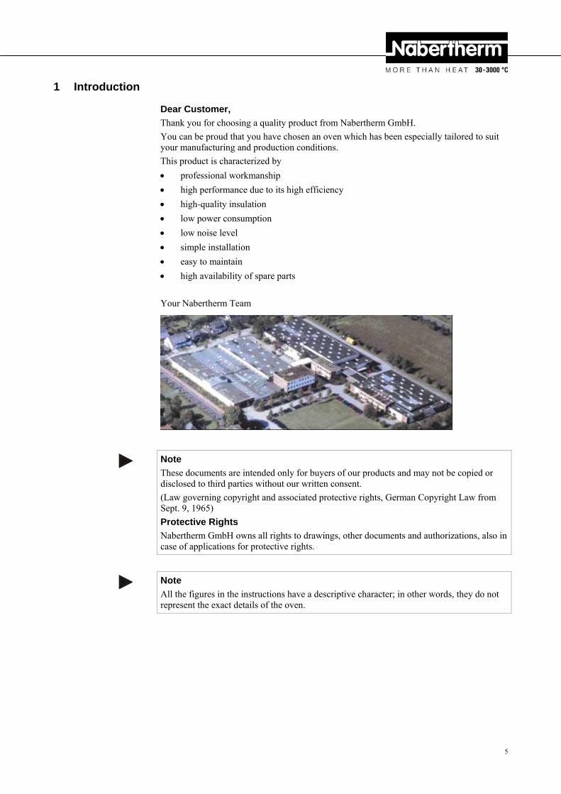
Dear Customer,
Thank you for choosing a quality product from Nabertherm GmbH.
You can be proud that you have chosen an oven which has been especially tailored to suit your manufacturing and production conditions.
This product is characterized by
professional workmanship
high performance due to its high efficiency
high-quality insulation
low power consumption
low noise level
simple installation
easy to maintain
high availability of spare parts
Your Nabertherm Team
Note
These documents are intended only for buyers of our products and may not be copied or disclosed to third parties without our written consent.
(Law governing copyright and associated protective rights, German Copyright Law from Sept. 9, 1965)
Protective Rights
Nabertherm GmbH owns all rights to drawings, other documents and authorizations, also in case of applications for protective rights.
Note
All the figures in the instructions have a descriptive character; in other words, they do not represent the exact details of the oven.
Pos: 3 /=== Seitenumbruch === @ 0\mod_1158819844943_0.doc @ 2983 @
6
Pos: 4 /TD/Einleitung/Produktbeschreibung/Öfen/Überschrift - Produktbeschreibung 1.1 @ 0\mod_1167821943807_51.doc @ 5103 @ 2
1.1 Product Description Pos: 5 /TD/Einleitung/Produktbeschreibung/Öfen/Toplader Top/HO/F - Produktbeschreibung @ 11\mod_1273211641392_51.doc @ 75193 @
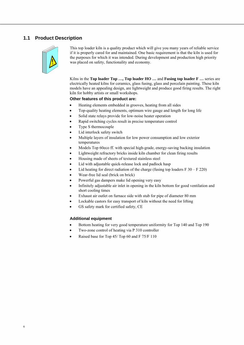
This top loader kiln is a quality product which will give you many years of reliable service if it is properly cared for and maintained. One basic requirement is that the kiln is used for the purposes for which it was intended. During development and production high priority was placed on safety, functionality and economy.
Kilns in the Top loader Top …, Top loader HO … and Fusing top loader F … series are electrically heated kilns for ceramics, glass fusing, glass and porcelain painting. These kiln models have an appealing design, are lightweight and produce good firing results. The right kiln for hobby artists or small workshops.
Other features of this product are:
Heating elements embedded in grooves, heating from all sides Top-quality heating elements, optimum wire gauge and length for long life Solid state relays provide for low-noise heater operation Rapid switching cycles result in precise temperature control Type S thermocouple Lid interlock safety switch Multiple layers of insulation for low power consumption and low exterior
temperatures Models Top 60eco ff. with special high-grade, energy-saving backing insulation Lightweight refractory bricks inside kiln chamber for clean firing results Housing made of sheets of textured stainless steel Lid with adjustable quick-release lock and padlock hasp Lid heating for direct radiation of the charge (fusing top loaders F 30 – F 220) Wear-free lid seal (brick on brick) Powerful gas dampers make lid opening very easy Infinitely adjustable air inlet in opening in the kiln bottom for good ventilation and
short cooling times Exhaust air outlet on furnace side with stub for pipe of diameter 80 mm Lockable castors for easy transport of kiln without the need for lifting GS safety mark for certified safety, CE
Additional equipment
Bottom heating for very good temperature uniformity for Top 140 and Top 190 Two-zone control of heating via P 310 controller
Raised base for Top 45/ Top 60 and F 75/F 110
Pos: 6 /=== Seitenumbruch === @ 0\mod_1158819844943_0.doc @ 2983 @
7
Pos: 7 /TD/Einleitung/Lieferumfang/Öfen/Überschrift - Gesamtübersicht der Anlage @ 1\mod_1174302636992_51.doc @ 11332 @ 2
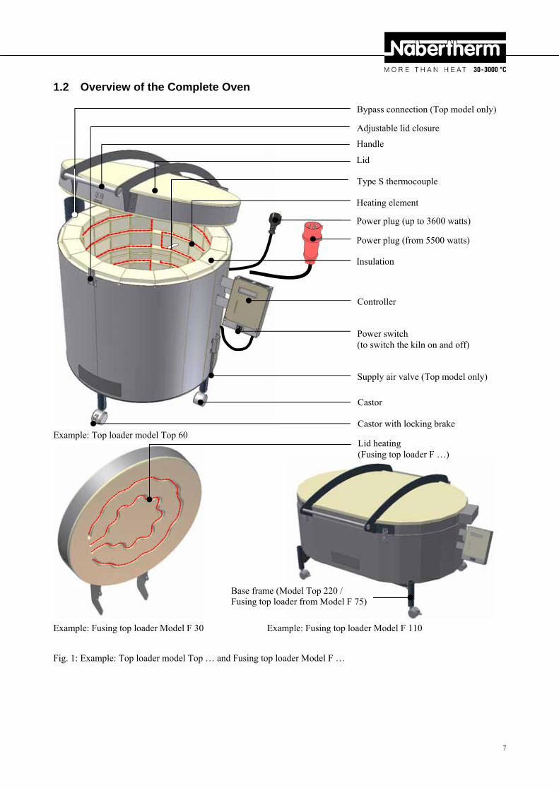
1.2 Overview of the Complete Oven Pos: 8 /TD/Einleitung/Lieferumfang/Öfen/Gesamtübersicht Toplader Top und Fusing-Toplader F @ 11\mod_1273211552229_51.doc @ 75176 @
Example: Top loader model Top 60
Example: Fusing top loader Model F 30 Example: Fusing top loader Model F 110
Fig. 1: Example: Top loader model Top … and Fusing top loader Model F …
Pos: 9 /=== Seitenumbruch === @ 0\mod_1158819844943_0.doc @ 2983 @
Controller
Power switch (to switch the kiln on and off)
Bypass connection (Top model only)
Adjustable lid closure
Handle
Lid
Type S thermocouple
Heating element
Power plug (up to 3600 watts)
Power plug (from 5500 watts)
Insulation
Supply air valve (Top model only)
Castor
Castor with locking brake
Lid heating (Fusing top loader F …)
Base frame (Model Top 220 / Fusing top loader from Model F 75)
8
Pos: 10 /TD/Einleitung/Lieferumfang/Öfen/ Gesamtübersicht Hobby HO @ 13\mod_1288941957853_51.doc @ 107213 @
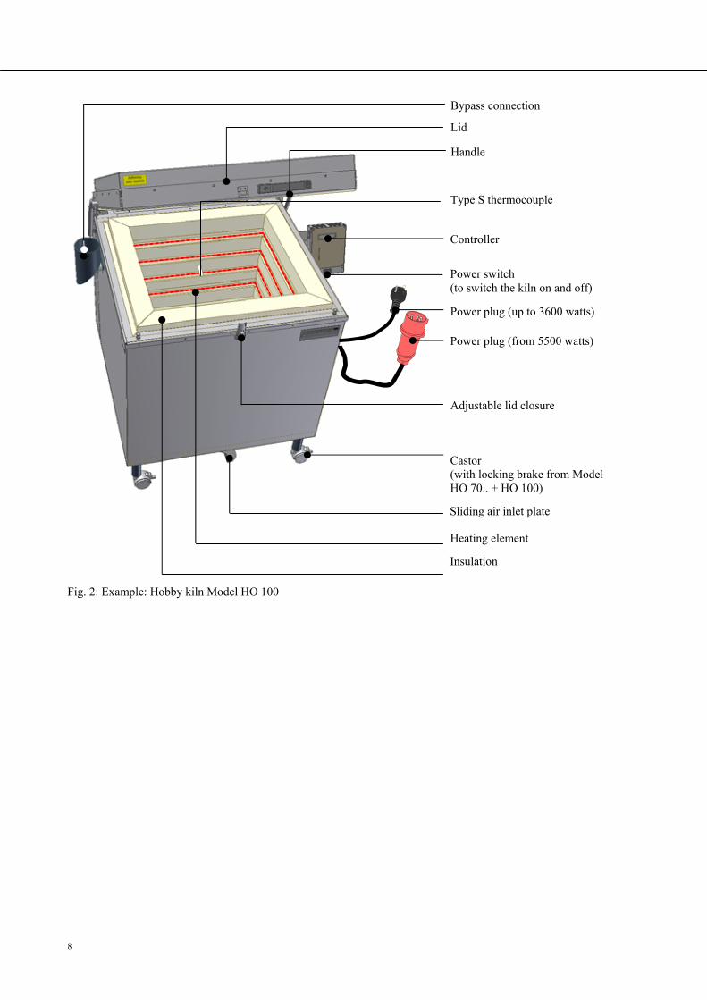
Fig. 2: Example: Hobby kiln Model HO 100
Pos: 11 /=== Seitenumbruch === @ 0\mod_1158819844943_0.doc @ 2983 @
Controller
Power switch (to switch the kiln on and off)
Bypass connection
Adjustable lid closure
Handle
Lid
Type S thermocouple
Heating element
Power plug (up to 3600 watts)
Power plug (from 5500 watts)
Insulation
Sliding air inlet plate
Castor (with locking brake from Model HO 70.. + HO 100)
9
Pos: 12 /TD/Einleitung/Produktbeschreibung/Öfen/Überschrift - Entschlüsselung der Modellbezeichnung @ 2\mod_1184245078907_51.doc @ 19775 @ 2
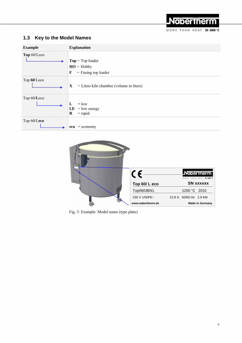
1.3 Key to the Model Names Pos: 13 /TD/Einleitung/Produktbeschreibung/Öfen/Entschlüssellung der Modellbezeichnung Top, HO und F @ 13\mod_1289220515672_51.doc @ 107253 @
Example Explanation
Top 60/Leco
Top = Top loader
HO = Hobby
F = Fusing top loader
Top 60/Leco
X = Liters kiln chamber (volume in liters)
Top 60/Leco
L = low LE = low energy R = rapid
Top 60/Leco
eco = economy
Pos: 14 /TD/Einleitung/Produktbeschreibung/Öfen/Entschlüssellung der Modellbezeichnung Top, HO und F - Grafik @ 13\mod_1289220599264_51.doc @ 107276 @
www.nabertherm.de Made in Germany
SN xxxxxx
Fig. 3: Example: Model name (type plate)
Pos: 15 /=== Seitenumbruch === @ 0\mod_1158819844943_0.doc @ 2983 @
Top0603BN1 1200 °C 2010
Top 60/ L eco
230 V 1/N/PE~ 12.8 A 50/60 Hz 2.9 kW
10
Pos: 16 /TD/Einleitung/Lieferumfang/Öfen/Überschrift - Lieferumfang @ 0\mod_1167822508130_51.doc @ 5112 @ 2
1.4 Scope of Delivery Pos: 17 /TD/Einleitung/Lieferumfang/Öfen/Top-HO-F - Lieferumfang @ 13\mod_1289229496838_51.doc @ 107345 @
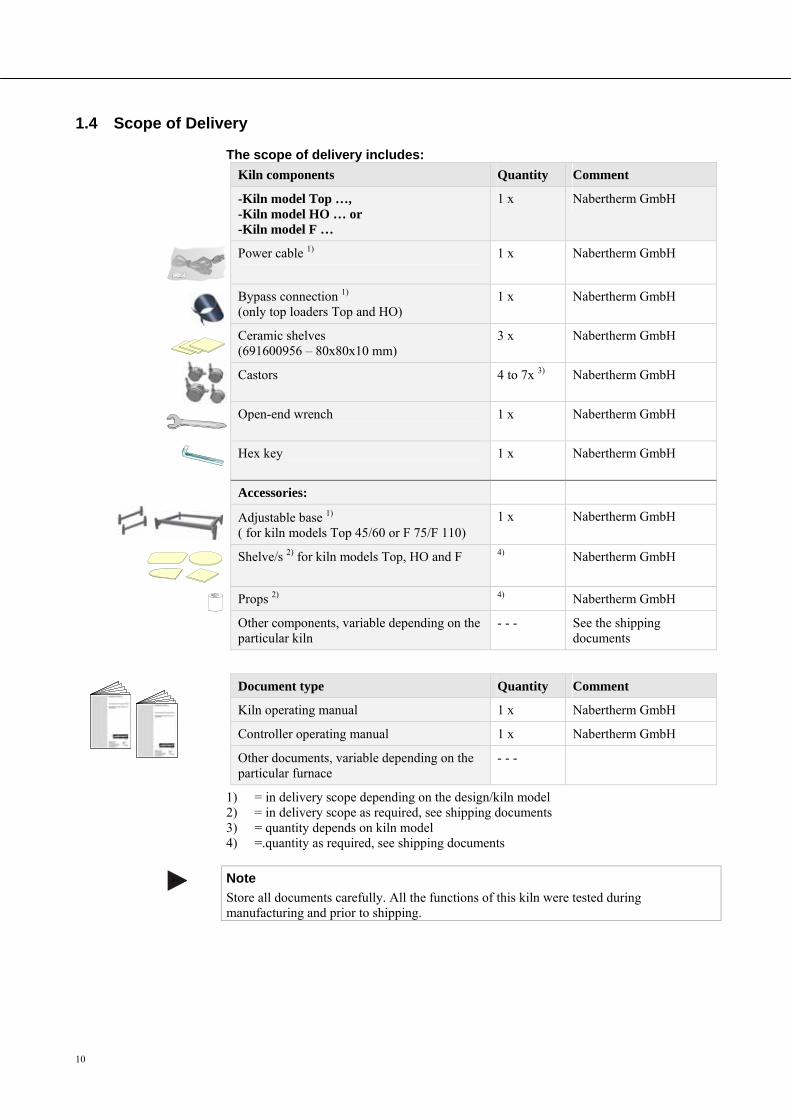
The scope of delivery includes:
Kiln components Quantity Comment
-Kiln model Top …, -Kiln model HO … or -Kiln model F …
1 x Nabertherm GmbH
Power cable 1)
1 x Nabertherm GmbH
Bypass connection 1) (only top loaders Top and HO)
1 x Nabertherm GmbH
Ceramic shelves (691600956 – 80x80x10 mm)
3 x Nabertherm GmbH
Castors
4 to 7x 3) Nabertherm GmbH
Open-end wrench
1 x Nabertherm GmbH
Hex key
1 x Nabertherm GmbH
Accessories:
Adjustable base 1) ( for kiln models Top 45/60 or F 75/F 110)
1 x Nabertherm GmbH
Shelve/s 2) for kiln models Top, HO and F 4) Nabertherm GmbH
Props 2) 4) Nabertherm GmbH
Other components, variable depending on the particular kiln
- - - See the shipping documents
Document type Quantity Comment
Kiln operating manual 1 x Nabertherm GmbH
Controller operating manual 1 x Nabertherm GmbH
Other documents, variable depending on the particular furnace
- - -
1) = in delivery scope depending on the design/kiln model 2) = in delivery scope as required, see shipping documents 3) = quantity depends on kiln model 4) =.quantity as required, see shipping documents
Note
Store all documents carefully. All the functions of this kiln were tested during manufacturing and prior to shipping.
Pos: 18 /=== Seitenumbruch === @ 0\mod_1158819844943_0.doc @ 2983 @
11
Pos: 19 /TD/Einleitung/Technische Daten/Öfen/Überschrift - Technische Daten - mit Hinweis @ 0\mod_1167822840737_51.doc @ 5121 @ 1
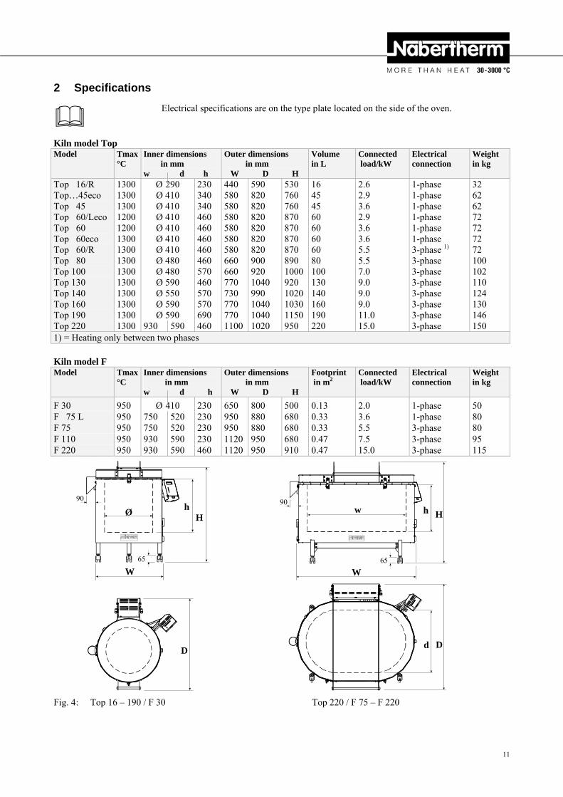
2 Specifications
Electrical specifications are on the type plate located on the side of the oven.
Pos: 20 /TD/Einleitung/Technische Daten/Öfen/Modell-Tabelle für Top-Öfen - 1 @ 13\mod_1289313490353_51.doc @ 107373 @
Kiln model Top Model Tmax
°C Inner dimensions in mm w d h
Outer dimensions in mm W D H
Volumein L
Connected load/kW
Electrical connection
Weightin kg
Top 16/R Top…45eco Top 45 Top 60/Leco Top 60 Top 60eco Top 60/R Top 80 Top 100 Top 130 Top 140 Top 160 Top 190
1300 1300 1300 1200 1200 1300 1300 1300 1300 1300 1300 1300 1300
Ø 290 Ø 410 Ø 410 Ø 410 Ø 410 Ø 410 Ø 410 Ø 480 Ø 480 Ø 590 Ø 550 Ø 590 Ø 590
230 340 340 460 460 460 460 460 570 460 570 570 690
440 580 580 580 580 580 580 660 660 770 730 770 770
590 820 820 820 820 820 820 900 920 1040 990 1040 1040
530 760 760 870 870 870 870 890 1000920 102010301150
16 45 45 60 60 60 60 80 100 130 140 160 190
2.6 2.9 3.6 2.9 3.6 3.6 5.5 5.5 7.0 9.0 9.0 9.0 11.0
1-phase 1-phase 1-phase 1-phase 1-phase 1-phase 3-phase 1) 3-phase 3-phase 3-phase 3-phase 3-phase 3-phase
32 62 62 72 72 72 72 100 102 110 124 130 146
Top 220 1300 930 590 460 1100 1020 950 220 15.0 3-phase 150 1) = Heating only between two phases Pos: 21 /TD/Einleitung/Technische Daten/Öfen/Modell-Tabelle für F-Öfen - 1 @ 13\mod_1289317404179_51.doc @ 107419 @
Kiln model F Model Tmax
°C Inner dimensions in mm w d h
Outer dimensions in mm W D H
Footprint in m2
Connected load/kW
Electrical connection
Weightin kg
F 30 950 Ø 410 230 650 800 500 0.13 2.0 1-phase 50 F 75 L 950 750 520 230 950 880 680 0.33 3.6 1-phase 80 F 75 950 750 520 230 950 880 680 0.33 5.5 3-phase 80 F 110 950 930 590 230 1120 950 680 0.47 7.5 3-phase 95 F 220 950 930 590 460 1120 950 910 0.47 15.0 3-phase 115 Pos: 22 /TD/Einleitung/Technische Daten/Öfen/Modell-Tabelle für Top und F-Öfen - Zeichnung - 1 @ 13\mod_1289313563435_51.doc @ 107396 @
Fig. 4: Top 16 – 190 / F 30 Top 220 / F 75 – F 220
W
D
H w h
d
W
D
Ø h
H
90 90
65 65
12
Pos: 23 /TD/Einleitung/Technische Daten/Öfen/Modell-Tabelle für HO-Öfen - 1 @ 13\mod_1289317483630_51.doc @ 107442 @
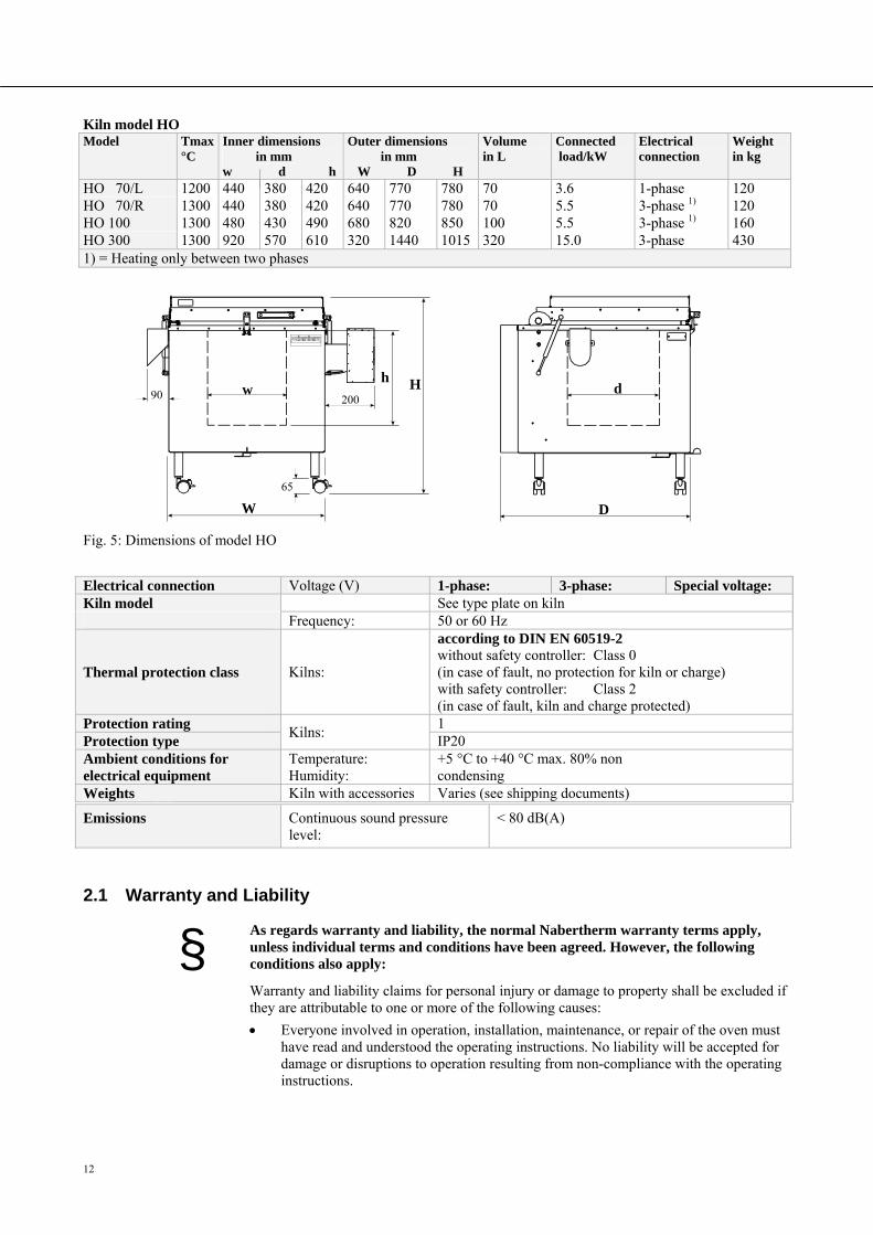
Kiln model HO Model Tmax
°C Inner dimensions in mm w d h
Outer dimensions in mm W D H
Volumein L
Connected load/kW
Electrical connection
Weightin kg
HO 70/L 1200 440 380 420 640 770 780 70 3.6 1-phase 120 HO 70/R 1300 440 380 420 640 770 780 70 5.5 3-phase 1) 120 HO 100 1300 480 430 490 680 820 850 100 5.5 3-phase 1) 160 HO 300 1300 920 570 610 320 1440 1015 320 15.0 3-phase 430 1) = Heating only between two phases Pos: 24 /TD/Einleitung/Technische Daten/Öfen/Modell-Tabelle für HO-Öfen - Zeichnung - 1 @ 13\mod_1289317573157_51.doc @ 107465 @
Fig. 5: Dimensions of model HO
Pos: 25 /TD/Einleitung/Technische Daten/Öfen/Tabelle für alle Top-HO und F-Öfen - 1 @ 13\mod_1289381485867_51.doc @ 107493 @
Electrical connection Voltage (V) 1-phase: 3-phase: Special voltage: Kiln model See type plate on kiln Frequency: 50 or 60 Hz
Thermal protection class Kilns:
according to DIN EN 60519-2 without safety controller: Class 0 (in case of fault, no protection for kiln or charge) with safety controller: Class 2 (in case of fault, kiln and charge protected)
Protection rating Kilns:
1 Protection type IP20 Ambient conditions for electrical equipment
Temperature: Humidity:
+5 °C to +40 °C max. 80% non condensing
Weights Kiln with accessories Varies (see shipping documents) Pos: 26 /TD/Einleitung/Technische Daten/Öfen/Tabelle Dauerschalldruckpegel < 80 dB(A) - 2 @ 1\mod_1170750985488_51.doc @ 8913 @
Emissions Continuous sound pressure level:
< 80 dB(A)
Pos: 27 /TD/Einleitung/Gewährleistung_Haftung/Überschrift - Gewährleistung und Haftung 1.1 @ 0\mod_1167822979492_51.doc @ 5130 @ 2
2.1 Warranty and Liability Pos: 28 /TD/Einleitung/Gewährleistung_Haftung/Öfen und Schaltanlagen - Gewährleistung und Haftung @ 0\mod_1157536440972_51.doc @ 1569 @
§ As regards warranty and liability, the normal Nabertherm warranty terms apply, unless individual terms and conditions have been agreed. However, the following conditions also apply:
Warranty and liability claims for personal injury or damage to property shall be excluded if they are attributable to one or more of the following causes:
Everyone involved in operation, installation, maintenance, or repair of the oven must have read and understood the operating instructions. No liability will be accepted for damage or disruptions to operation resulting from non-compliance with the operating instructions.
W D
H w h
d
65
90 200
13
Not using the oven as intended,
Improper installation, start-up, operation, or maintenance of the oven,
Operation of the oven with defective safety equipment or improperly installed or non-functioning safety and protective equipment,
Not observing the references in the operating instructions to transportation, storage, installation, start-up, operation, maintenance, or equipping the oven,
Making unauthorized changes to the oven,
Making unauthorized changes to the operating parameters,
Making unauthorized changes to the parameterization, the settings, or the program,
Original parts and accessories are designed especially for Nabertherm ovens. Replace parts only with original Nabertherm parts. Otherwise the warranty will be void. Nabertherm accepts absolutely no liability for damage caused by using parts that are not original Nabertherm parts.
Catastrophes due to third-party causes and force majeure.
Pos: 29 /TD/Sicherheit/Überschrift - Sicherheit @ 0\mod_1158843961540_51.doc @ 3103 @ 1
3 Safety Pos: 30 /TD/Sicherheit/Sicherheitssymbole/Warnhinweise-ISO-ANSI/Erläuterung ANSI Z535.6 @ 8\mod_1243323558881_51.doc @ 57444 @ 2
3.1 Explanation of the Symbols and Warnings
Note
In the following operating instructions, specific warnings are given to draw attention to residual risks that cannot be avoided when the oven is operating. These residual risks include dangers for humans/products/ the oven, and the environment.
The symbols used in the operating instructions are especially intended to draw attention to safety information.
The symbols used cannot replace the text of the safety information. Therefore, always read the entire text.
Graphic symbols correspond to ISO 3864. In accordance with the American National Standard Institute (ANSI) Z535.6 the following warning information and words are used in this document:
The general hazard symbol, in combination with the words CAUTION, WARNING and DANGER warns about the risk of serious injury. Observe the following information to prevent injury or death.
NOTICE Refers to a hazard that could damage or destroy the equipment.
CAUTION Refers to a hazard with a minor or medium risk of injury.

14
WARNING Refers to a hazard that could cause death, serious or irreversible injury.
DANGER Refers to a hazard that could directly cause death, serious or irreversible injury.
Structure of the warning: All warnings are structured as follows
WARNING
• Type and source of the danger
• Consequences of non-compliance
• Action to prevent danger
or
DANGER
• Type and source of the danger
• Consequences of non-compliance
• Action to prevent danger
Pos: 31 /TD/Sicherheit/Sicherheitssymbole/Warnhinweise-ISO-ANSI/Überschrift - Hinweissymbole in der Anleitung @ 9\mod_1247053429626_51.doc @ 62751 @
Information Symbols in the Instructions: Pos: 32 /TD/Sicherheit/Sicherheitssymbole/Warnhinweise-ISO-ANSI/Hinweis - Unter diesem Symbol erhalten Sie Anweisungshinweise und ... @ 9\mod_1247053932311_51.doc @ 62785 @
Note
Below this symbol you will find instructions and particularly useful information.
Pos: 33 /TD/Sicherheit/Sicherheitssymbole/Warnhinweise-ISO-ANSI/Piktogramm in der Anleitung - Gebot - Gebotszeichen - Wichtige Gebote sind zu befolgen @ 9\mod_1247056175982_51.doc @ 62853 @
Graphical symbols (optional) according to ISO 3864: Consequences, measures, and prohibitions
Reference texts: • Type and source of the danger • Possible consequences of non- compliance • Measures/prohibitions
Hazard symbol Indicates the risk of injury
Signal word Classifies the danger
Graphical symbols (optional) according to ISO 3864: Instructions or prohibitions
Graphical symbols (optional) according to ISO 3864: Consequences, measures, and prohibitions
Reference texts: • Type and source of the danger • Possible consequences of non- compliance
M /P hibiti
Hazard symbol Indicates the risk of injury
Signal word Classifies the danger
15
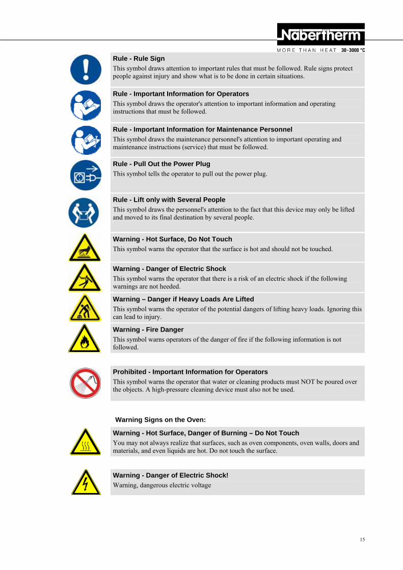
Rule - Rule Sign
This symbol draws attention to important rules that must be followed. Rule signs protect people against injury and show what is to be done in certain situations.
Pos: 34 /TD/Sicherheit/Sicherheitssymbole/Warnhinweise-ISO-ANSI/Piktogramm in der Anleitung - Gebot - Wichtige Information für den Bediener @ 9\mod_1247053200729_51.doc @ 62717 @
Rule - Important Information for Operators
This symbol draws the operator's attention to important information and operating instructions that must be followed.
Pos: 35 /TD/Sicherheit/Sicherheitssymbole/Warnhinweise-ISO-ANSI/Piktogramm in der Anleitung - Gebot - Wichtige Information für das Wartungspersonal @ 9\mod_1247053206042_51.doc @ 62734 @
Rule - Important Information for Maintenance Personnel
This symbol draws the maintenance personnel's attention to important operating and maintenance instructions (service) that must be followed.
Pos: 36 /TD/Sicherheit/Sicherheitssymbole/Warnhinweise-ISO-ANSI/Piktogramm in der Anleitung - Gebot - Netzstecker ziehen @ 9\mod_1247055471526_51.doc @ 62836 @
Rule - Pull Out the Power Plug
This symbol tells the operator to pull out the power plug.
Pos: 37 /TD/Sicherheit/Sicherheitssymbole/Warnhinweise-ISO-ANSI/Piktogramm in der Anleitung - Gebot - Anheben mit mehreren Personen @ 9\mod_1247063058002_51.doc @ 62938 @
Rule - Lift only with Several People
This symbol draws the personnel's attention to the fact that this device may only be lifted and moved to its final destination by several people.
Pos: 38 /TD/Sicherheit/Sicherheitssymbole/Warnhinweise-ISO-ANSI/Piktogramm in der Anleitung - Warnung - Heiße Oberfläche - Oberfläche nicht berühren @ 9\mod_1247054774780_51.doc @ 62802 @
Warning - Hot Surface, Do Not Touch
This symbol warns the operator that the surface is hot and should not be touched.
Pos: 39 /TD/Sicherheit/Sicherheitssymbole/Warnhinweise-ISO-ANSI/Piktogramm in der Anleitung - Warnung - elektrischer Schlag - zur Vermeidung Anweisung folgen @ 9\mod_1247055093892_51.doc @ 62819 @
Warning - Danger of Electric Shock
This symbol warns the operator that there is a risk of an electric shock if the following warnings are not heeded.
Pos: 40 /TD/Sicherheit/Sicherheitssymbole/Warnhinweise-ISO-ANSI/Piktogramm in der Anleitung - Warnung - Heben schwerer Lasten @ 9\mod_1247059891358_51.doc @ 62887 @
Warning – Danger if Heavy Loads Are Lifted
This symbol warns the operator of the potential dangers of lifting heavy loads. Ignoring this can lead to injury.
Pos: 41 /TD/Sicherheit/Sicherheitssymbole/Warnhinweise-ISO-ANSI/Piktogramm in der Anleitung - Warnung - Brandgefahr @ 9\mod_1251445272822_51.doc @ 65437 @
Warning - Fire Danger
This symbol warns operators of the danger of fire if the following information is not followed.
Pos: 42 /TD/Sicherheit/Sicherheitssymbole/Warnhinweise-ISO-ANSI/Piktogramm in der Anleitung - Gefahr - nicht mit Wasser überschütten @ 9\mod_1247826410886_51.doc @ 63819 @
Prohibited - Important Information for Operators
This symbol warns the operator that water or cleaning products must NOT be poured over the objects. A high-pressure cleaning device must also not be used.
Pos: 43 /TD/Sicherheit/Sicherheitssymbole/Warnhinweise-ISO-ANSI/Überschrift - Warnhinweissymbole an der Anlage @ 9\mod_1247053700273_51.doc @ 62768 @
Warning Signs on the Oven: Pos: 44 /TD/Sicherheit/Sicherheitssymbole/Warnhinweise-ISO-ANSI/Piktogramm an der Anlage - Warnung - Gefahr vor heißer Oberfläche und Verbrennung @ 9\mod_1247052957145_51.doc @ 62700 @
Warning - Hot Surface, Danger of Burning – Do Not Touch
You may not always realize that surfaces, such as oven components, oven walls, doors and materials, and even liquids are hot. Do not touch the surface.
Pos: 45 /TD/Sicherheit/Sicherheitssymbole/Warnhinweise-ISO-ANSI/Piktogramm an der Anlage - Warnung - Gefahren durch elektrischen Strom @ 9\mod_1247052639824_51.doc @ 62683 @
Warning - Danger of Electric Shock!
Warning, dangerous electric voltage
Pos: 46 /=== Seitenumbruch === @ 0\mod_1158819844943_0.doc @ 2983 @ Pos: 47 /TD/Sicherheit/Überschrift - Bestimmungsgemäße Verwendung @ 0\mod_1167823503921_51.doc @ 5148 @ 2
16
3.2 Intended Use Pos: 48 /TD/Sicherheit/Bestimmungsgemäße Verwendung Top-HO und F-Öfen @ 13\mod_1289384913818_51.doc @ 107516 @ Safety
This Nabertherm kiln was designed and built to comply with various carefully chosen harmonized standards and technical specifications. Hence, it corresponds to the state of the art and assures the greatest level of safety.
Kilns in the Top and HO series are electrically heated kilns for firing ceramics, glass fusing, glass and porcelain painting. Kilns in the F series are for glass fusing, glass and porcelain painting.
Any other use, such as processing of products other than those for which the kiln was intended as well as handling hazardous materials or materials dangerous to health is deemed IMPROPER and such uses must be approved in writing by Nabertherm.
Under certain circumstances gases or materials may be released from the materials in the kilns that settle on the insulation or the heating elements and destroy them. If applicable, read the labels and instructions on the packaging of materials that you use.
Changes to the kiln require the written approval of Nabertherm. Protective components (if applicable) must not be removed, overridden, or deactivated.
The set-up instructions and safety regulations must be followed, otherwise the kiln will be considered improperly used, effectively cancelling any claims against Nabertherm GmbH.
The kiln must not be opened when it is hot (above 200 °C). If it is opened above 200 °C, the kiln can be destroyed or it can lead to increased wear of the following components: door seal, heating elements, and kiln housing
Operation with power sources, products, operating equipment, auxiliary materials, etc., which are listed as hazardous or which may in any way harm the health of the operator is prohibited.
The kiln must not be filled with materials or substances that release explosive gases or vapors. Only materials and substances whose properties are known may be used.
This kiln was designed for private and commercial use. The kiln is NOT to be used for heating food, animals, wood, grains, etc.
The kiln must NOT be used to heat the workplace. Do NOT use the kiln to melt ice or for similar purposes. Do NOT use the kiln as a clothes dryer.
Note
Applicable safety instructions are contained in the individual chapters.
Pos: 49 /=== Seitenumbruch === @ 0\mod_1158819844943_0.doc @ 2983 @
17
Pos: 50 /TD/Sicherheit/Überschrift - Anforderungen an den Betreiber der Anlage @ 0\mod_1167823775531_51.doc @ 5157 @ 2
3.3 Requirements for the Oven Operator Pos: 51 /TD/Sicherheit/Anforderungen an den Betreiber der Ofens Top-HO und F @ 13\mod_1289388704974_51.doc @ 107539 @
The set-up instructions and safety regulations must be followed, otherwise the kiln will be deemed to have been used improperly, effectively cancelling any claims against Nabertherm GmbH.
This level of safety can be achieved only if all the necessary measures have been taken. It depends on the kiln operator's diligence in planning these measures and controlling how they are carried out.
The operator must ensure that
This kiln is NOT used by certain persons (including children) with restricted physical, sensorial or mental capabilities or who have insufficient experience and/or insufficient knowledge, unless they are supervised by a person who is responsible for their safety or are instructed in how to use the kiln. Children should be supervised to make sure that they do not play with the kiln.
When ceramics, clay, or glaze are fired, they can emit gases and vapors that are harmful to your health. It is therefore necessary to make sure that the "exhaust gases" emitted from the exhaust air opening are directed outdoors in a suitable manner (ventilate the working area). If adequate ventilation cannot be ensured at the working area, the "exhaust gases" must be removed via a pipe (see "Exhaust Gas System").
Before placing materials in the kiln, check whether they could harm or destroy the insulation or the heating elements. Materials that could damage the insulation include: alkalis, alkaline earths, metal vapors, metal oxides, chlorine compounds, phosphorous compounds, and halogens. If applicable, read the labels and instructions on the packaging of materials that you use.
The kiln is operated only in a perfect operating condition and, in particular, that the functions of the safety components are checked regularly.
Necessary personal protective equipment is available. Example: protective gloves, suitable apron, etc.
This instruction manual is to be kept beside the kiln. These instructions must be available at all times for anyone working with or on the kiln;
All the safety and operating instruction signs on the kiln can be read properly. Damaged or unreadable signs must be replaced immediately,
Personnel are informed regularly about all issues involving occupational safety and environmental protection and are familiar with all the operating instructions, especially those involving safety,
If the kiln is used commercially: Observe the safety regulations applicable in your country. In Germany, the kiln must be checked by a qualified electrician at defined intervals in accordance with a regulation issued by the employers' accident insurance fund.
Pos: 52 /TD/Allgemeine Hinweise (für alle Anleitungen)/Hinweis - In Deutschland ist die allgemeine Unfallverhütungsvorschriften VBG bzw. BGZ zu beachten. @ 3\mod_1193667801739_51.doc @ 26122 @
Note
In Germany, the general accident protection guidelines of VBG or BGZ must be observed. The national accident prevention regulations of the country of operation apply.
Pos: 53 /=== Seitenumbruch === @ 0\mod_1158819844943_0.doc @ 2983 @ Pos: 54 /TD/Sicherheit/Überschrift - Schutzkleidung @ 0\mod_1167825795750_51.doc @ 5175 @ 2
3.4 Protective Clothing Pos: 55 /TD/Sicherheit/Schutzkleidung - Hitzebeständige Handschuhe tragen @ 9\mod_1246542013306_51.doc @ 62473 @
Wear heat-resistant gloves to protect your hands.
Pos: 56 /=== Seitenumbruch === @ 0\mod_1158819844943_0.doc @ 2983 @
18
Pos: 57 /TD/Sicherheit/Überschrift - Grundlegende Maßnahmen bei Normalbetrieb @ 0\mod_1167825919827_51.doc @ 5184 @ 2
3.5 Basic Measures During Normal Operation Pos: 58 /TD/Sicherheit/Grundlegende Maßnahmen bei Normalbetrieb Top-HO und F Öfen @ 13\mod_1289395735652_51.doc @ 107562 @
Risks during normal operation
Before switching the kiln on, check and ensure that only authorized persons are in the working area of the kiln and that no one can be injured as a result of operating the kiln.
Each time, before starting production check and ensure that all the safety equipment functions as intended (for example, that the contact safety switch switches the heating off when the lid is opened).
Before starting production each time, check the kiln for obvious damage and ensure that it is operated only in a perfect condition. Report any defects to Nabertherm Service immediately.
Before starting production each time, remove all materials and objects that are not needed for production from the working area.
At least once every day (see also Servicing and Maintenance) check the following:
Check the kiln for obvious external damage (visual check), for example insulation, heating elements, power cable, exhaust gas system, if applicable.
Check that all safety equipment is functioning (for example, that the contact safety switch switches the heating off when the lid is opened).
Pos: 59 /TD/Sicherheit/Überschrift - Grundlegende Maßnahmen im Notfall @ 1\mod_1170943369267_51.doc @ 9093 @ 2
3.6 Basic Measures in Case of Emergency Pos: 60 /TD/Sicherheit/Überschrift - Verhalten im Notfall @ 1\mod_1170949904855_51.doc @ 9123 @ 3
3.6.1 What to do in an Emergency Pos: 61 /TD/Allgemeine Hinweise (für alle Anleitungen)/Hinweis - Das Stillsetzen im Notfall ist vorgesehen durch Ziehen des Netzsteckers. @ 6\mod_1222062836860_51.doc @ 42829 @
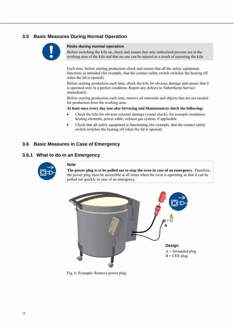
Note
The power plug is to be pulled out to stop the oven in case of an emergency. Therefore, the power plug must be accessible at all times when the oven is operating so that it can be pulled out quickly in case of an emergency.
Fig. 6: Example: Remove power plug
Pos: 62 /TD/Sicherheit/Grundlegende Maßnahmen im Notfall - Top-HO und F-Öfen mit Netzstecker - Grafik @ 13\mod_1289400219457_51.doc @ 107585 @ Pos: 63 /TD/Allgemeine Hinweise (für alle Anleitungen)/Warnung - Bei unerwarteten Vorgängen im Ofen (z.B. starke Rauchentwicklung oder Geruchsbelästigung) @ 4\mod_1205306579737_51.doc @ 34218 @
Design
A = Grounded plug B = CEE plug
A
19
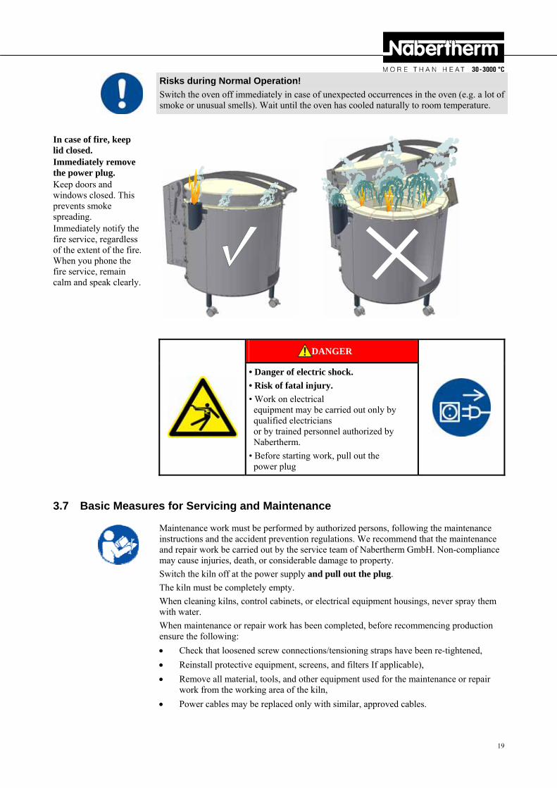
Risks during Normal Operation!
Switch the oven off immediately in case of unexpected occurrences in the oven (e.g. a lot of smoke or unusual smells). Wait until the oven has cooled naturally to room temperature.
Pos: 64 /TD/Allgemeine Hinweise (für alle Anleitungen)/Warnung - Bei unerwarteten Vorgängen darf der Ofen nicht geöffnet werden - Grafik Top-HO und F @ 13\mod_1289403819547_51.doc @ 107636 @
In case of fire, keep lid closed. Immediately remove the power plug. Keep doors and windows closed. This prevents smoke spreading. Immediately notify the fire service, regardless of the extent of the fire. When you phone the fire service, remain calm and speak clearly.
Pos: 65 /TD/Sicherheit/Sicherheitssymbole/Warnhinweise-ISO-ANSI/Warnsymbol_Gefahr - Elektrischer Schlag - Piktogramm elektr. Schlag - Hauptschalter @ 9\mod_1247472185096_51.doc @ 63063 @
DANGER
• Danger of electric shock.
• Risk of fatal injury.
• Work on electrical equipment may be carried out only by qualified electricians or by trained personnel authorized by Nabertherm.
• Before starting work, pull out the power plug
Pos: 66 /TD/Sicherheit/Überschrift - Grundlegende Maßnahmen bei Wartung und Instandhaltung @ 0\mod_1167826060620_51.doc @ 5193 @ 2
3.7 Basic Measures for Servicing and Maintenance Pos: 67 /TD/Sicherheit/Grundlegende Maßnahmen bei Wartung und Instandhaltung Top, HO und F - Öfen @ 13\mod_1291107854956_51.doc @ 109556 @
Maintenance work must be performed by authorized persons, following the maintenance instructions and the accident prevention regulations. We recommend that the maintenance and repair work be carried out by the service team of Nabertherm GmbH. Non-compliance may cause injuries, death, or considerable damage to property.
Switch the kiln off at the power supply and pull out the plug.
The kiln must be completely empty.
When cleaning kilns, control cabinets, or electrical equipment housings, never spray them with water.
When maintenance or repair work has been completed, before recommencing production ensure the following:
Check that loosened screw connections/tensioning straps have been re-tightened,
Reinstall protective equipment, screens, and filters If applicable),
Remove all material, tools, and other equipment used for the maintenance or repair work from the working area of the kiln,
Power cables may be replaced only with similar, approved cables. Pos: 68 /=== Seitenumbruch === @ 0\mod_1158819844943_0.doc @ 2983 @ Pos: 69 /TD/Sicherheit/Überschrift - Allgemeine Gefahren an der Anlage @ 0\mod_1168596796288_51.doc @ 6014 @ 2
20
3.8 General Risks with the Oven Pos: 70 /TD/Sicherheit/Allgemeine Gefahren (Verbrennung, Quetschen, Strom) - Top, HO und F @ 13\mod_1289466766104_51.doc @ 107663 @
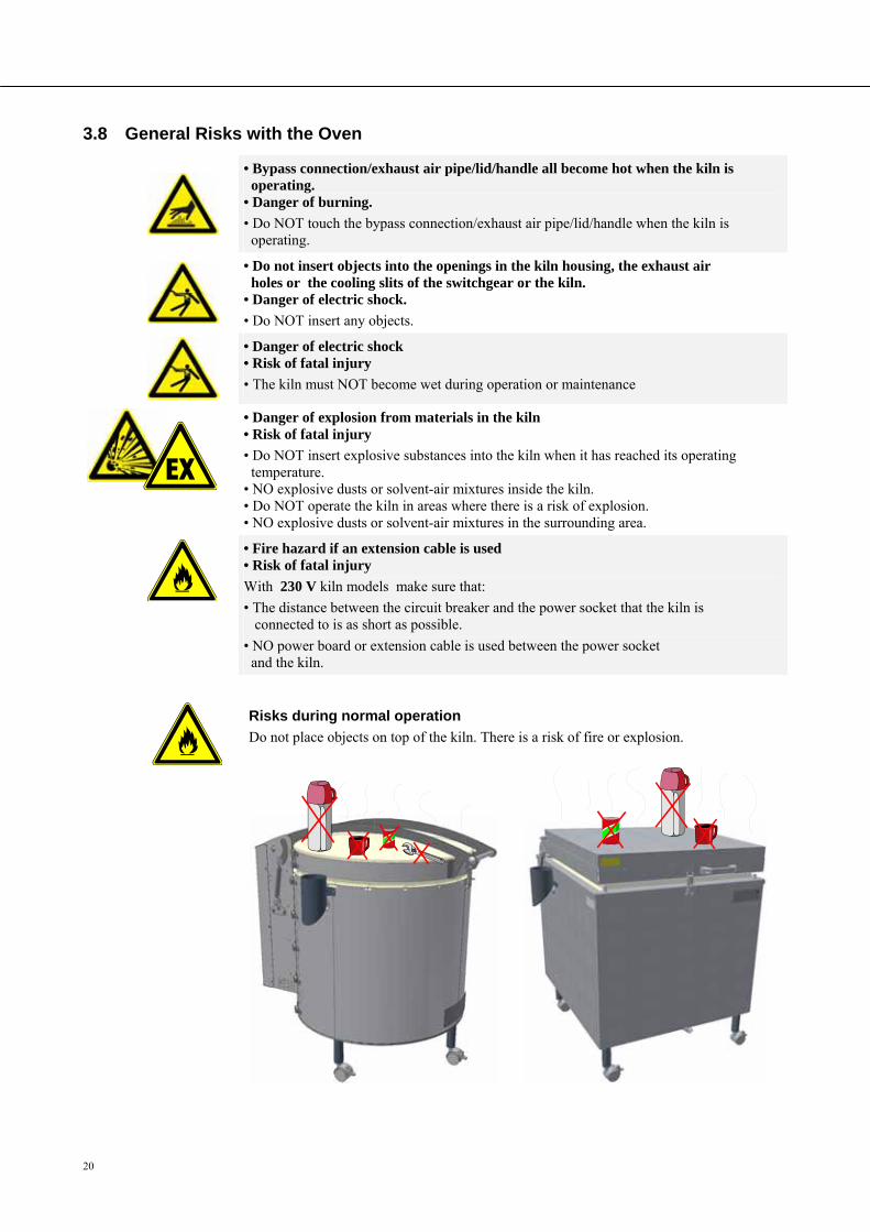
• Bypass connection/exhaust air pipe/lid/handle all become hot when the kiln is operating. • Danger of burning.
• Do NOT touch the bypass connection/exhaust air pipe/lid/handle when the kiln is operating.
• Do not insert objects into the openings in the kiln housing, the exhaust air holes or the cooling slits of the switchgear or the kiln. • Danger of electric shock.
• Do NOT insert any objects.
• Danger of electric shock • Risk of fatal injury
• The kiln must NOT become wet during operation or maintenance
• Danger of explosion from materials in the kiln • Risk of fatal injury
• Do NOT insert explosive substances into the kiln when it has reached its operating temperature. • NO explosive dusts or solvent-air mixtures inside the kiln. • Do NOT operate the kiln in areas where there is a risk of explosion. • NO explosive dusts or solvent-air mixtures in the surrounding area.
• Fire hazard if an extension cable is used • Risk of fatal injury
With 230 V kiln models make sure that:
• The distance between the circuit breaker and the power socket that the kiln is connected to is as short as possible.
• NO power board or extension cable is used between the power socket and the kiln.
Pos: 71 /TD/Sicherheit/Warnung - Es dürfen keine Gegenstände auf dem Top-HO und F Ofen abgeledt/abgestellt werden @ 13\mod_1289402437366_51.doc @ 107613 @
Risks during normal operation
Do not place objects on top of the kiln. There is a risk of fire or explosion.
Pos: 72 /TD/Transport_Montage_Inbetriebnahme/Erstinbetriebnahme/Überschrift - Transport, Montage und Erstinbetriebnahme @ 0\mod_1158844227416_51.doc @ 3112 @ 1
21
4 Transportation, Installation, and Commissioning Pos: 73 /TD/Transport_Montage_Inbetriebnahme/Erstinbetriebnahme/Überschrift - Anlieferung @ 0\mod_1167826534889_51.doc @ 5220 @ 2
4.1 Delivery Pos: 74 /TD/Transport_Montage_Inbetriebnahme/Erstinbetriebnahme/Anlieferung Top, HO und F Öfen - (Hinweise allgemein) @ 13\mod_1289468478869_51.doc @ 107686 @
Check that everything is complete
Compare the delivered items with the delivery note and the purchase order documents. Immediately notify the carrier and Nabertherm GmbH of any missing or damaged parts, as complaints at a later date cannot be acknowledged.
Danger of injury
When the kiln is being lifted, parts of the kiln or the kiln itself could topple over, slip, or fall. Before the kiln is lifted, make sure no one is in the working area. Appropriate protective gloves must be worn.
Safety Instructions
Industrial trucks (e.g.: crane/pallet truck) must be operated only by authorized personnel. The operator bears sole responsibility for safe operation and the load.
When the kiln is being lifted, make sure that the ends of the forks or the load do not catch on neighboring goods. Use a crane to move tall parts, such as control cabinets.
Lifting gear must be attached only to positions that have been designated for this purpose.
Attachments, piping, or cable conduits must never be used to affix lifting gear.
Attach transportation equipment only to positions intended for this purpose.
Note
Wear protective gloves when installing the kiln.
Risks during normal operation
Suspended loads are dangerous. Working beneath a suspended load is prohibited. There is a risk of fatal injury.
Note
Safety and accident prevention guidelines applicable for forklift trucks must be followed.
Pos: 75 /TD/Transport_Montage_Inbetriebnahme/Erstinbetriebnahme/Anlieferung von Öfen mit einem Hubwagen @ 2\mod_1184672460200_51.doc @ 20000 @
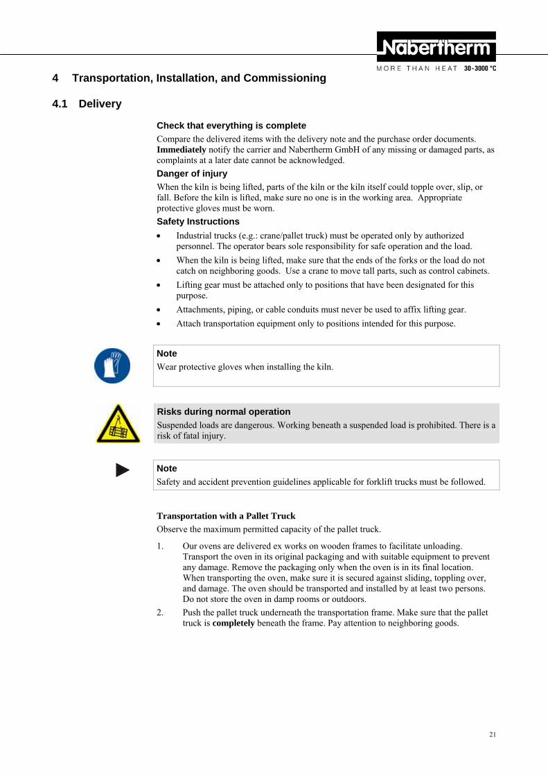
Transportation with a Pallet Truck
Observe the maximum permitted capacity of the pallet truck.
1. Our ovens are delivered ex works on wooden frames to facilitate unloading. Transport the oven in its original packaging and with suitable equipment to prevent any damage. Remove the packaging only when the oven is in its final location. When transporting the oven, make sure it is secured against sliding, toppling over, and damage. The oven should be transported and installed by at least two persons. Do not store the oven in damp rooms or outdoors.
2. Push the pallet truck underneath the transportation frame. Make sure that the pallet truck is completely beneath the frame. Pay attention to neighboring goods.
22
Fig. 7: Pallet truck is pushed completely beneath the transportation frame
3. Lift the oven carefully and pay attention to its center of gravity. When the oven is being lifted, make sure that the ends of the forks or the load do not catch on neighboring goods.
4. Make sure that the oven is balanced safely; if not, attach securing equipment. Push the oven carefully, slowly and with the pallet truck at its lowest position. Do not transport the oven on inclines.
5. Carefully lower the oven at its final position. Pay attention to neighboring goods. Try not to set it down too abruptly.
Pos: 76 /TD/Sicherheit/Sicherheitssymbole/Warnhinweise-ISO-ANSI/Warnsymbol_Vorsicht - Rutschen/Kippen des Gerätes - Piktogramm Kippen/Heben/Anheben @ 9\mod_1247064081950_51.doc @ 62955 @
CAUTION
• Device may slip or topple over. • Damage to the device.
• Risk of injury from lifting heavy loads.
• Transport device only in original packaging. • Several people must carry the device.
Pos: 77 /=== Seitenumbruch === @ 0\mod_1158819844943_0.doc @ 2983 @ Pos: 78 /TD/Transport_Montage_Inbetriebnahme/Erstinbetriebnahme/Überschrift - Auspacken @ 2\mod_1184739517985_51.doc @ 20013 @ 2
4.2 Unpacking Pos: 79 /TD/Allgemeine Hinweise (für alle Anleitungen)/Hinweis - Allgemeiner Hinweis zur Verpackung (z.B. Laboröfen) @ 3\mod_1192437185846_51.doc @ 23509 @
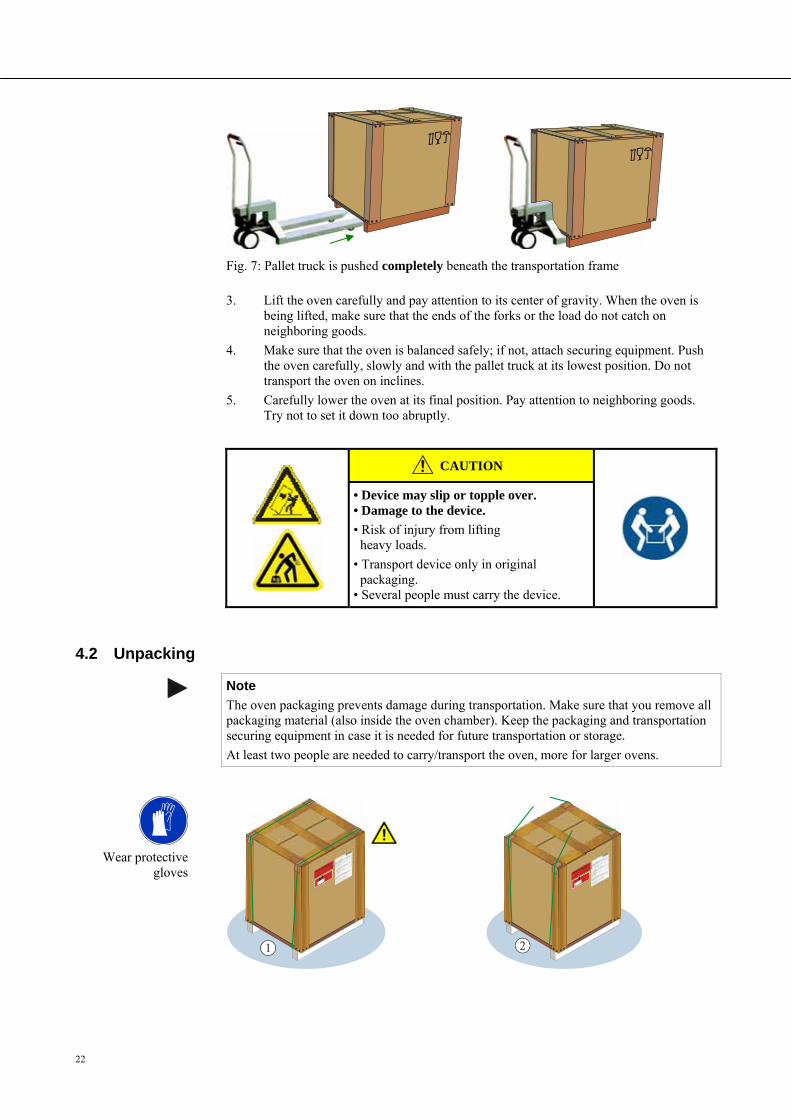
Note
The oven packaging prevents damage during transportation. Make sure that you remove all packaging material (also inside the oven chamber). Keep the packaging and transportation securing equipment in case it is needed for future transportation or storage.
At least two people are needed to carry/transport the oven, more for larger ovens.
Pos: 80 /TD/Transport_Montage_Inbetriebnahme/Erstinbetriebnahme/Auspacken Trockenschrank TR ... - Teil 1 @ 9\mod_1246978000133_51.doc @ 62643 @
Wear protective
gloves
1
2
23
2
3
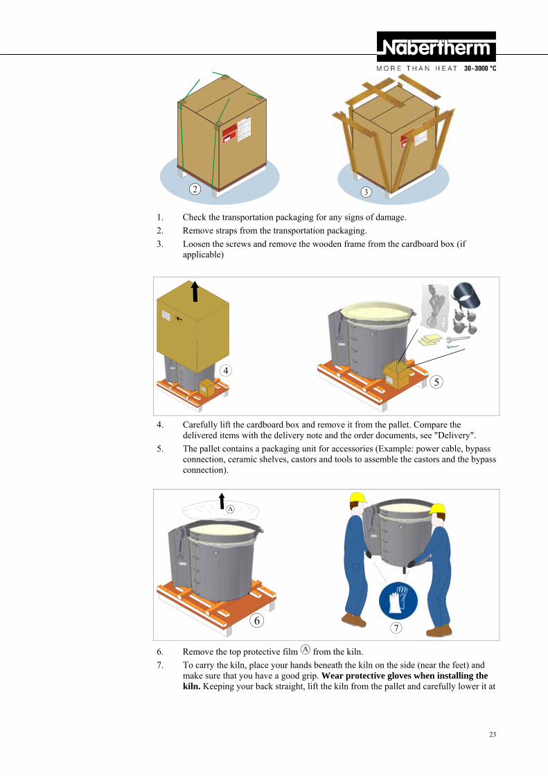
1. Check the transportation packaging for any signs of damage.
2. Remove straps from the transportation packaging.
3. Loosen the screws and remove the wooden frame from the cardboard box (if applicable)
Pos: 81 /TD/Transport_Montage_Inbetriebnahme/Erstinbetriebnahme/Auspacken Top und F Öfen - Teil 2 @ 13\mod_1289472062898_51.doc @ 107709 @
4
5
4. Carefully lift the cardboard box and remove it from the pallet. Compare the delivered items with the delivery note and the order documents, see "Delivery".
5. The pallet contains a packaging unit for accessories (Example: power cable, bypass connection, ceramic shelves, castors and tools to assemble the castors and the bypass connection).
6
A
7
6. Remove the top protective film A from the kiln.
7. To carry the kiln, place your hands beneath the kiln on the side (near the feet) and make sure that you have a good grip. Wear protective gloves when installing the kiln. Keeping your back straight, lift the kiln from the pallet and carefully lower it at
24
the point where it is to be installed. The kiln should be transported by at least 2 people.
8
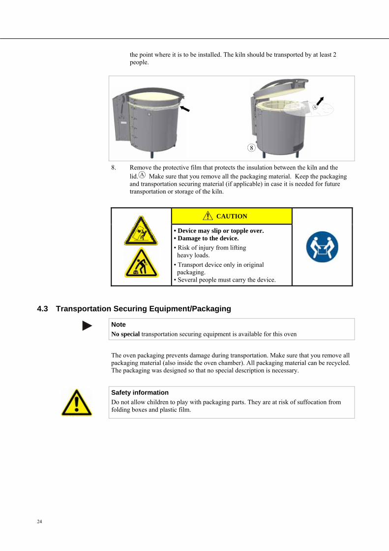
A
8. Remove the protective film that protects the insulation between the kiln and the lid. A Make sure that you remove all the packaging material. Keep the packaging and transportation securing material (if applicable) in case it is needed for future transportation or storage of the kiln.
Pos: 82 /TD/Sicherheit/Sicherheitssymbole/Warnhinweise-ISO-ANSI/Warnsymbol_Vorsicht - Rutschen/Kippen des Gerätes - Piktogramm Kippen/Heben/Anheben @ 9\mod_1247064081950_51.doc @ 62955 @
CAUTION
• Device may slip or topple over. • Damage to the device.
• Risk of injury from lifting heavy loads.
• Transport device only in original packaging. • Several people must carry the device.
Pos: 83 /=== Seitenumbruch === @ 0\mod_1158819844943_0.doc @ 2983 @ Pos: 84 /TD/Transport_Montage_Inbetriebnahme/Erstinbetriebnahme/Überschrift - Transportsicherung/Verpackung @ 0\mod_1167826775847_51.doc @ 5229 @ 2
4.3 Transportation Securing Equipment/Packaging Pos: 85 /TD/Transport_Montage_Inbetriebnahme/Erstinbetriebnahme/Verpackung - Allgemeine Hinweise zur Verpackung - keine spezielle Transportsicherung @ 1\mod_1171004073117_51.doc @ 9153 @
Note
No special transportation securing equipment is available for this oven
The oven packaging prevents damage during transportation. Make sure that you remove all packaging material (also inside the oven chamber). All packaging material can be recycled. The packaging was designed so that no special description is necessary.
Pos: 86 /TD/Transport_Montage_Inbetriebnahme/Erstinbetriebnahme/Verpackung - Allgemeine Hinweise zur Verpackung - Kinder und Verpackungsmaterial @ 13\mod_1290686355811_51.doc @ 109504 @
Safety information
Do not allow children to play with packaging parts. They are at risk of suffocation from folding boxes and plastic film.
Pos: 87 /=== Seitenumbruch === @ 0\mod_1158819844943_0.doc @ 2983 @
25
Pos: 88 /TD/Transport_Montage_Inbetriebnahme/Erstinbetriebnahme/Überschrift - Bauliche- und Anschlussvoraussetzungen @ 0\mod_1167826890943_51.doc @ 5238 @ 2
4.4 Constructional and Connection Requirements Pos: 89 /TD/Transport_Montage_Inbetriebnahme/Erstinbetriebnahme/Überschrift - Aufstellung (Standort des Ofens) @ 2\mod_1184848718972_51.doc @ 20166 @ 3
4.4.1 Installation (Oven Location) Pos: 90 /TD/Transport_Montage_Inbetriebnahme/Erstinbetriebnahme/Standort eines Top, HO und F - Ofens @ 13\mod_1289479898145_51.doc @ 107732 @
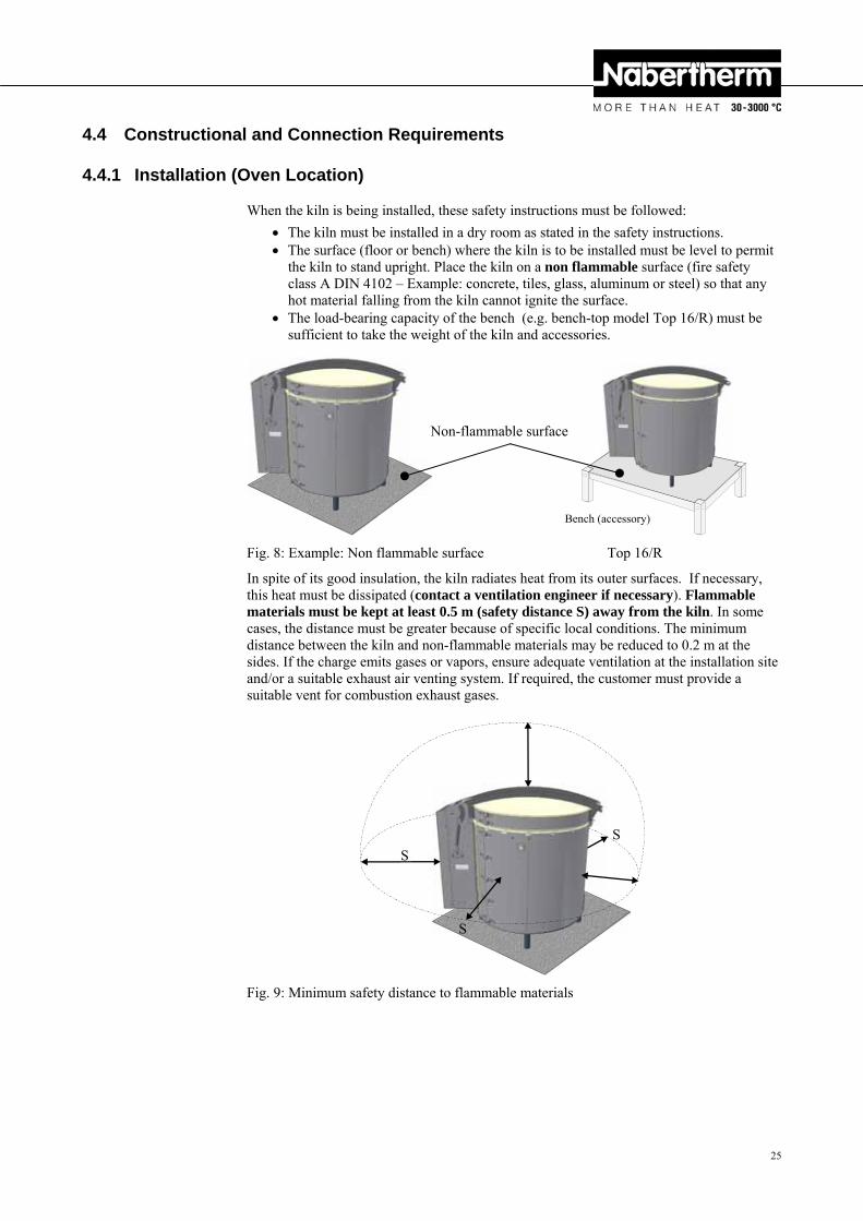
When the kiln is being installed, these safety instructions must be followed:
The kiln must be installed in a dry room as stated in the safety instructions. The surface (floor or bench) where the kiln is to be installed must be level to permit
the kiln to stand upright. Place the kiln on a non flammable surface (fire safety class A DIN 4102 – Example: concrete, tiles, glass, aluminum or steel) so that any hot material falling from the kiln cannot ignite the surface.
The load-bearing capacity of the bench (e.g. bench-top model Top 16/R) must be sufficient to take the weight of the kiln and accessories.
Fig. 8: Example: Non flammable surface Top 16/R
In spite of its good insulation, the kiln radiates heat from its outer surfaces. If necessary, this heat must be dissipated (contact a ventilation engineer if necessary). Flammable materials must be kept at least 0.5 m (safety distance S) away from the kiln. In some cases, the distance must be greater because of specific local conditions. The minimum distance between the kiln and non-flammable materials may be reduced to 0.2 m at the sides. If the charge emits gases or vapors, ensure adequate ventilation at the installation site and/or a suitable exhaust air venting system. If required, the customer must provide a suitable vent for combustion exhaust gases.
Fig. 9: Minimum safety distance to flammable materials
Pos: 91 /TD/Sicherheit/Sicherheitssymbole/Warnhinweise-ISO-ANSI/Warnsymbol_Gefahr - Brandgefahr - Piktogramm Brandgefahr @ 9\mod_1247148035738_51.doc @ 63010 @
Non-flammable surface
S
S
Bench (accessory)
S
26
DANGER
• Fire- danger to health.
• Risk of fatal injury.
• Adequate ventilation must be ensured at the installation location to conduct waste heat and any exhaust gases away.
Pos: 92 /TD/Allgemeine Hinweise (für alle Anleitungen)/Hinweis - Vor Inbetriebnahme des Ofens sollte dieser 24 Stunden am Aufstellungsort akklimatisiert .. @ 3\mod_1195568014336_51.doc @ 27871 @
Note
Before starting the oven for the first time, allow it to acclimatize at its installation location for 24 hours.
Pos: 93 /=== Seitenumbruch === @ 0\mod_1158819844943_0.doc @ 2983 @ Pos: 94 /TD/Transport_Montage_Inbetriebnahme/Erstinbetriebnahme/Überschrift - Montage, Installation und Anschluss @ 0\mod_1167827976269_51.doc @ 5292 @ 2
4.5 Assembly, Installation, and Connection Pos: 95 /TD/Transport_Montage_Inbetriebnahme/Erstinbetriebnahme/Überschrift - Montage der Untergestellerhöhung (Zubehör-Untergestellerhöhung) @ 13\mod_1290432714317_51.doc @ 108766 @ 3
4.5.1 Assembling the Base Extension (Accessory) Pos: 96 /TD/Transport_Montage_Inbetriebnahme/Erstinbetriebnahme/Montage der Untergestellerhöhung F-Öfen @ 13\mod_1290433433198_51.doc @ 108789 @
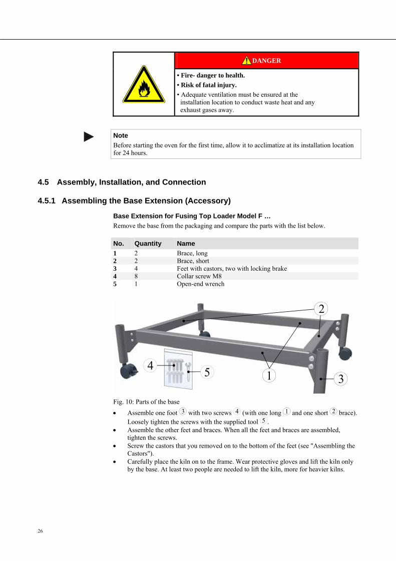
Base Extension for Fusing Top Loader Model F …
Remove the base from the packaging and compare the parts with the list below.
No. Quantity Name
1 2 Brace, long 2 2 Brace, short 3 4 Feet with castors, two with locking brake 4 8 Collar screw M8 5 1 Open-end wrench
1
2
34 5
Fig. 10: Parts of the base
Assemble one foot 3 with two screws 4 (with one long 1 and one short 2 brace). Loosely tighten the screws with the supplied tool 5 .
Assemble the other feet and braces. When all the feet and braces are assembled, tighten the screws.
Screw the castors that you removed on to the bottom of the feet (see "Assembling the Castors").
Carefully place the kiln on to the frame. Wear protective gloves and lift the kiln only by the base. At least two people are needed to lift the kiln, more for heavier kilns.
Pos: 97 /TD/Transport_Montage_Inbetriebnahme/Erstinbetriebnahme/Montage der Untergestellerhöhung Top-Öfen @ 13\mod_1290611225954_51.doc @ 109314 @
27
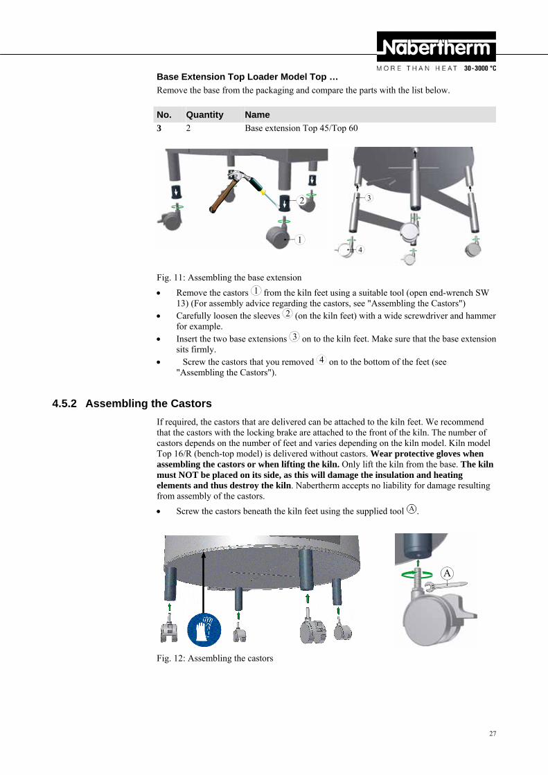
Base Extension Top Loader Model Top …
Remove the base from the packaging and compare the parts with the list below.
No. Quantity Name
3 2 Base extension Top 45/Top 60
1
2
3
4
Fig. 11: Assembling the base extension
Remove the castors 1 from the kiln feet using a suitable tool (open end-wrench SW 13) (For assembly advice regarding the castors, see "Assembling the Castors")
Carefully loosen the sleeves 2 (on the kiln feet) with a wide screwdriver and hammer for example.
Insert the two base extensions 3 on to the kiln feet. Make sure that the base extension sits firmly.
Screw the castors that you removed 4 on to the bottom of the feet (see "Assembling the Castors").
Pos: 98 /=== Seitenumbruch === @ 0\mod_1158819844943_0.doc @ 2983 @ Pos: 99 /TD/Transport_Montage_Inbetriebnahme/Erstinbetriebnahme/Überschrift - Montage der Transportrollen @ 13\mod_1289819020312_51.doc @ 107922 @ 3
4.5.2 Assembling the Castors Pos: 100 /TD/Transport_Montage_Inbetriebnahme/Erstinbetriebnahme/Montage der Transportrollen @ 13\mod_1289819198441_51.doc @ 107945 @
If required, the castors that are delivered can be attached to the kiln feet. We recommend that the castors with the locking brake are attached to the front of the kiln. The number of castors depends on the number of feet and varies depending on the kiln model. Kiln model Top 16/R (bench-top model) is delivered without castors. Wear protective gloves when assembling the castors or when lifting the kiln. Only lift the kiln from the base. The kiln must NOT be placed on its side, as this will damage the insulation and heating elements and thus destroy the kiln. Nabertherm accepts no liability for damage resulting from assembly of the castors.
Screw the castors beneath the kiln feet using the supplied tool A .
13
A
Fig. 12: Assembling the castors
28
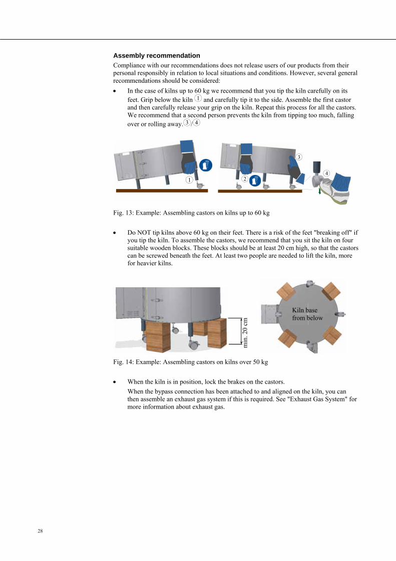
Assembly recommendation
Compliance with our recommendations does not release users of our products from their personal responsibly in relation to local situations and conditions. However, several general recommendations should be considered:
In the case of kilns up to 60 kg we recommend that you tip the kiln carefully on its feet. Grip below the kiln 1 and carefully tip it to the side. Assemble the first castor and then carefully release your grip on the kiln. Repeat this process for all the castors. We recommend that a second person prevents the kiln from tipping too much, falling over or rolling away. 3 / 4
1
2
3
4
Fig. 13: Example: Assembling castors on kilns up to 60 kg
Do NOT tip kilns above 60 kg on their feet. There is a risk of the feet "breaking off" if you tip the kiln. To assemble the castors, we recommend that you sit the kiln on four suitable wooden blocks. These blocks should be at least 20 cm high, so that the castors can be screwed beneath the feet. At least two people are needed to lift the kiln, more for heavier kilns.
Fig. 14: Example: Assembling castors on kilns over 50 kg
When the kiln is in position, lock the brakes on the castors.
When the bypass connection has been attached to and aligned on the kiln, you can then assemble an exhaust gas system if this is required. See "Exhaust Gas System" for more information about exhaust gas.
Pos: 101 /=== Seitenumbruch === @ 0\mod_1158819844943_0.doc @ 2983 @
min
. 20
cm
Kiln base from below

29
Pos: 102 /TD/Transport_Montage_Inbetriebnahme/Erstinbetriebnahme/Überschrift - Montage des Bypass-Stutzens @ 13\mod_1289811687101_51.doc @ 107876 @ 3
4.5.3 Assembling the Bypass Connection Pos: 103 /TD/Transport_Montage_Inbetriebnahme/Erstinbetriebnahme/Montage des Bypass-Stutzens @ 13\mod_1289811827645_51.doc @ 107899 @
The bypass connection that is part of the delivery is fixed to the side of the kiln. Kilns in the top loader F series… have no bypass connection. Kiln model Top 16/R is delivered without a bypass connection. This model is ventilated via a hole in the middle of the lid.
At the position where the bypass connection is fixed are two screws 1 to assemble it; these must be removed beforehand.
Place the bypass connection 2 with the screws on to the correct position on the side of the kiln and fix it with suitable tools.
1
2
Fig. 15: Assembling the bypass connection
When the bypass connection has been attached to and aligned on the kiln, you can then assemble an exhaust gas system if this is required. See "Exhaust Gas System" for more information about exhaust gas.
Fig. 16: Assembling the exhaust gas piping on the bypass connection
Pos: 104 /=== Seitenumbruch === @ 0\mod_1158819844943_0.doc @ 2983 @
Bypass connection
Assembling the exhaust air piping: If required, see "Exhaust Gas System"
30
Pos: 105 /TD/Transport_Montage_Inbetriebnahme/Erstinbetriebnahme/Überschrift - Abgasführung @ 0\mod_1167828513042_51.doc @ 5310 @ 3
4.5.4 Waste Gas System Pos: 106 /TD/Transport_Montage_Inbetriebnahme/Erstinbetriebnahme/Abgasführung beim Top, HO und F - Öfen allgemeiner Text @ 13\mod_1289490231021_51.doc @ 107755 @
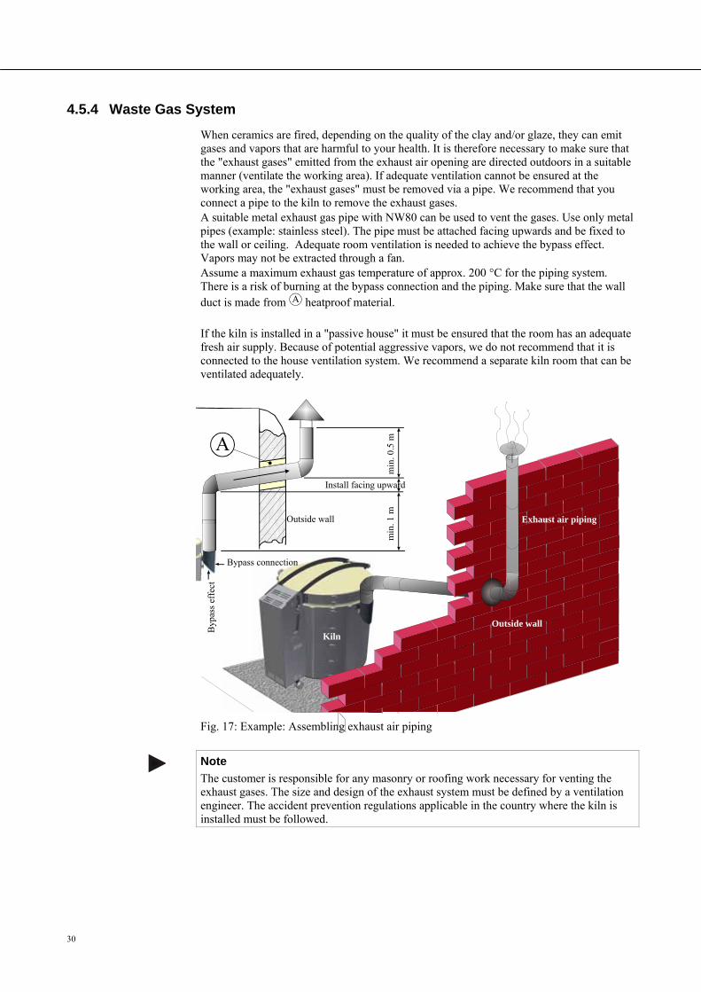
When ceramics are fired, depending on the quality of the clay and/or glaze, they can emit gases and vapors that are harmful to your health. It is therefore necessary to make sure that the "exhaust gases" emitted from the exhaust air opening are directed outdoors in a suitable manner (ventilate the working area). If adequate ventilation cannot be ensured at the working area, the "exhaust gases" must be removed via a pipe. We recommend that you connect a pipe to the kiln to remove the exhaust gases. A suitable metal exhaust gas pipe with NW80 can be used to vent the gases. Use only metal pipes (example: stainless steel). The pipe must be attached facing upwards and be fixed to the wall or ceiling. Adequate room ventilation is needed to achieve the bypass effect. Vapors may not be extracted through a fan. Assume a maximum exhaust gas temperature of approx. 200 °C for the piping system. There is a risk of burning at the bypass connection and the piping. Make sure that the wall duct is made from A heatproof material.
Pos: 107 /TD/Transport_Montage_Inbetriebnahme/Erstinbetriebnahme/Abgasführung beim Top, HO und F - Öfen Empfehlungen-Lüftung, Passivhaus usw. @ 13\mod_1290680678132_51.doc @ 109458 @
If the kiln is installed in a "passive house" it must be ensured that the room has an adequate fresh air supply. Because of potential aggressive vapors, we do not recommend that it is connected to the house ventilation system. We recommend a separate kiln room that can be ventilated adequately.
Pos: 108 /TD/Transport_Montage_Inbetriebnahme/Erstinbetriebnahme/Abgasführung beim Top, HO und F - Öfen - Grafik @ 13\mod_1290680601272_51.doc @ 109435 @
Fig. 17: Example: Assembling exhaust air piping
Note
The customer is responsible for any masonry or roofing work necessary for venting the exhaust gases. The size and design of the exhaust system must be defined by a ventilation engineer. The accident prevention regulations applicable in the country where the kiln is installed must be followed.
Pos: 109 /=== Seitenumbruch === @ 0\mod_1158819844943_0.doc @ 2983 @
A
min
. 0.5
m
min
. 1 m
Install facing upward
Bypass connection
Byp
ass
effe
ct
Outside wall
Outside wall
Exhaust air piping
Kiln
31
Pos: 110 /TD/Transport_Montage_Inbetriebnahme/Erstinbetriebnahme/Überschrift - 1.1.1 Anschluss an das Elektronetz @ 0\mod_1168599727688_51.doc @ 6050 @ 3
4.5.5 Connecting the Oven to the Power Supply Pos: 111 /TD/Transport_Montage_Inbetriebnahme/Erstinbetriebnahme/Anschluss an das Elektronetz - Top, HO und F - Öfen @ 13\mod_1289807121450_51.doc @ 107853 @
The customer must ensure that the surface has adequate load-bearing capacity and that the necessary energy (electricity) is provided.
The kiln must be installed according to its intended use. The power connection must correspond to the values on the kiln's type plate.
The power socket must be close to the kiln and be easily accessible. The safety requirements are not met if the kiln is not connected to a socket with a protective ground contact.
With 230 V kiln models pay attentions that: the distance between the circuit breaker and the power socket that the kiln is connected to is as short as possible. NO power board or extension cable is used between the power socket and the kiln.
The power cable must not be damaged. Do not place any objects on the power cable. Lay the cable so that no one can stand on it or trip over it.
Power cables may be replaced only with similar, approved cables.
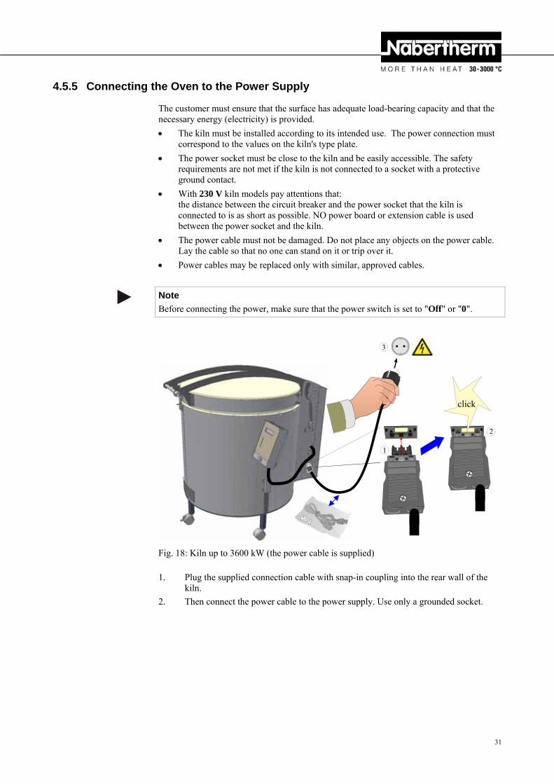
Note
Before connecting the power, make sure that the power switch is set to "Off" or "0".
1
2
3
Fig. 18: Kiln up to 3600 kW (the power cable is supplied)
1. Plug the supplied connection cable with snap-in coupling into the rear wall of the kiln.
2. Then connect the power cable to the power supply. Use only a grounded socket.
click
32
11
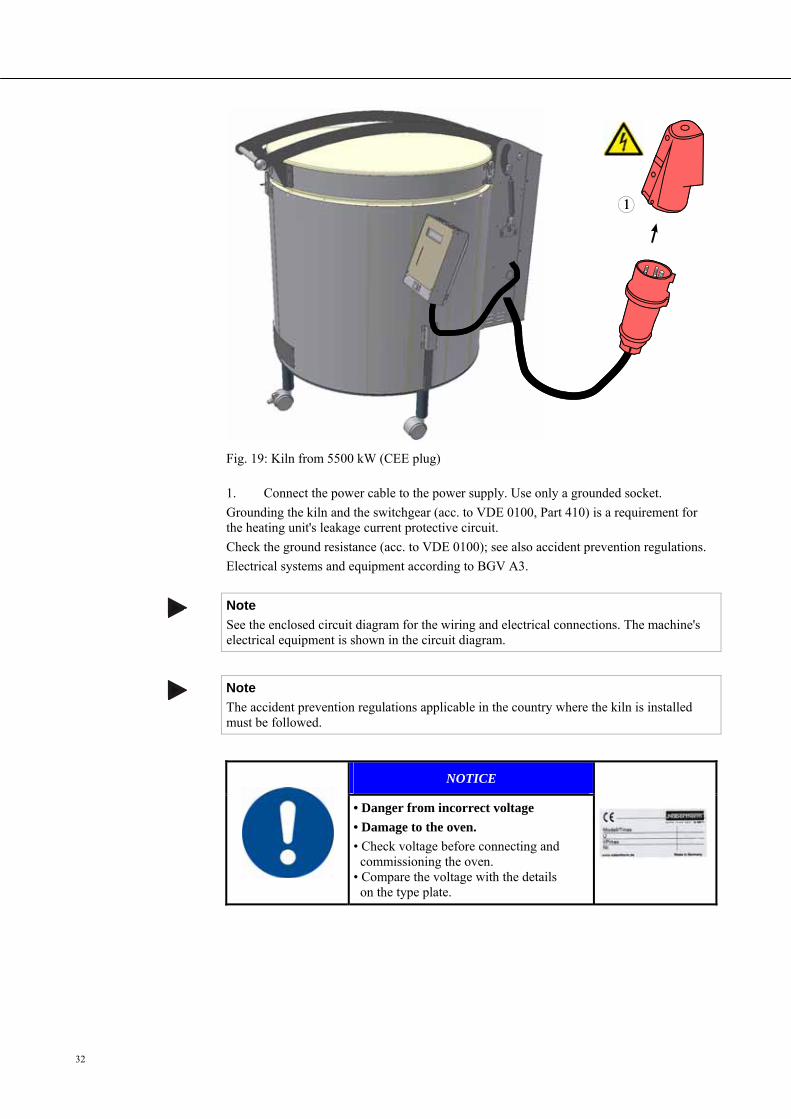
Fig. 19: Kiln from 5500 kW (CEE plug)
1. Connect the power cable to the power supply. Use only a grounded socket.
Grounding the kiln and the switchgear (acc. to VDE 0100, Part 410) is a requirement for the heating unit's leakage current protective circuit.
Check the ground resistance (acc. to VDE 0100); see also accident prevention regulations.
Electrical systems and equipment according to BGV A3.
Note
See the enclosed circuit diagram for the wiring and electrical connections. The machine's electrical equipment is shown in the circuit diagram.
Note
The accident prevention regulations applicable in the country where the kiln is installed must be followed.
Pos: 112 /TD/Sicherheit/Sicherheitssymbole/Warnhinweise-ISO-ANSI/Warnsymbol_Achtung - falsche Netzspannung - Piktogramm Gebotszeichen @ 9\mod_1247475231381_51.doc @ 63131 @
NOTICE
• Danger from incorrect voltage
• Damage to the oven.
• Check voltage before connecting and commissioning the oven. • Compare the voltage with the details on the type plate.
Pos: 113 /=== Seitenumbruch === @ 0\mod_1158819844943_0.doc @ 2983 @
33
Pos: 114 /TD/Transport_Montage_Inbetriebnahme/Erstinbetriebnahme/Überschrift - Erstinbetriebnahme @ 0\mod_1167828977720_51.doc @ 5337 @ 2
4.6 Commissioning Pos: 115 /TD/Transport_Montage_Inbetriebnahme/Erstinbetriebnahme/Erstinbetriebnahme Top, HO und F - Öfen - 1 @ 13\mod_1289914140994_51.doc @ 108088 @
Read the section on "Safety". When the kiln is put into operation, the following safety information must also be observed to prevent serious injury, damage to the kiln, and damage to other property.
Make sure that the instructions and information in the instruction manual and the controller instructions are observed and followed.
Before starting the kiln for the first time, make sure that all tools, foreign parts, and transportation securing equipment have been removed.
Before you switch on the kiln, make sure that you know what to do in case of faults or emergencies.
Before placing materials in the kiln, check whether they could harm or destroy the insulation or the heating elements. Materials that could damage the insulation include: alkalis, alkaline earths, metal vapors, metal oxides, chlorine compounds, phosphorous compounds, and halogens. If applicable, read the labels and instructions on the packaging of materials that you use.
Pos: 116 /TD/Allgemeine Hinweise (für alle Anleitungen)/Hinweis - Vor Inbetriebnahme des Ofens sollte dieser 24 Stunden am Aufstellungsort akklimatisiert .. @ 3\mod_1195568014336_51.doc @ 27871 @
Note
Before starting the oven for the first time, allow it to acclimatize at its installation location for 24 hours.
Pos: 117 /TD/Transport_Montage_Inbetriebnahme/Erstinbetriebnahme/Überschrift - Empfehlung für das erste Aufheizen des Ofens @ 0\mod_1167829134269_51.doc @ 5346 @ 2
4.7 Recommendations for Heating the Oven for the First Time Pos: 118 /TD/Transport_Montage_Inbetriebnahme/Erstinbetriebnahme/Empfehlung für das erste Aufheizen des Ofens Top, HO und F - Öfen @ 13\mod_1289915719331_51.doc @ 108134 @
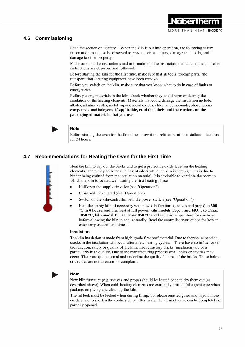
Heat the kiln to dry out the bricks and to get a protective oxide layer on the heating elements. There may be some unpleasant odors while the kiln is heating. This is due to binder being emitted from the insulation material. It is advisable to ventilate the room in which the kiln is located well during the first heating phase.
Half open the supply air valve (see "Operation")
Close and lock the lid (see "Operation")
Switch on the kiln/controller with the power switch (see "Operation")
Heat the empty kiln, if necessary with new kiln furniture (shelves and props) to 500 °C in 6 hours, and then heat at full power; kiln models Top… and HO… to Tmax 1050 °C, kiln model F… to Tmax 950 °C and keep this temperature for one hour before allowing the kiln to cool naturally. Read the controller instructions for how to enter temperatures and times.
Insulation
The kiln insulation is made from high-grade fireproof material. Due to thermal expansion, cracks in the insulation will occur after a few heating cycles. These have no influence on the function, safety or quality of the kiln. The refractory bricks (insulation) are of a particularly high quality. Due to the manufacturing process small holes or cavities may occur. These are quite normal and underline the quality features of the bricks. These holes or cavities are not a reason for complaint.
Note
New kiln furniture (e.g. shelves and props) should be heated once to dry them out (as described above). When cold, heating elements are extremely brittle. Take great care when packing, emptying and cleaning the kiln.
The lid lock must be locked when during firing. To release emitted gases and vapors more quickly and to shorten the cooling phase after firing, the air inlet valve can be completely or partially opened.

34
Pos: 119 /TD/Allgemeine Hinweise (für alle Anleitungen)/Hinweis - Möglichkeit die Temperatur über die Nenntemperatur einzustellen ... @ 13\mod_1290680126925_51.doc @ 109412 @
Note
At high firing temperatures a slit may become visible along the edge of the lid. This is normal and does not compromise the kiln's function or safety.
Pos: 120 /=== Seitenumbruch === @ 0\mod_1158819844943_0.doc @ 2983 @ Pos: 121 /TD/Betrieb_Bedienung/Überschrift - Bedienung 1 @ 3\mod_1186740685002_51.doc @ 20988 @ 1
5 Operation Pos: 122 /TD/Betrieb_Bedienung/Controller/B150/B130/B170/C280/C290/C295/P320/Überschrift - Controller @ 2\mod_1186739941084_51.doc @ 20936 @ 2
5.1 Controller Pos: 123 /TD/Betrieb_Bedienung/Bedienung Top, HO und F - Öfen - Controller - Grafik @ 13\mod_1289898331278_51.doc @ 108019 @
Madein Germany
T3
wait time 3 time 4time 2time 1
T2
T1
wait time 3 time 4time 2time 1
T2
T1
Fig. 20: Example: Controller and power switch
Pos: 124 /TD/Betrieb_Bedienung/Bedienung Top, HO und F - Öfen - Controller - Text @ 13\mod_1289898594068_51.doc @ 108042 @
1. The control current is switched off and on with the power switch 1 . When the control power is switched on, the controller type, version number and temperature are shown in the controller display 2 3 . Example: ). When the temperature is shown in the controller display, the controller is ready for operation.
2. The required heating and cooling programs are set on the controller 3 . See the separate instructions for a description of the controller.
Pos: 125 /TD/Allgemeine Hinweise (für alle Anleitungen)/Hinweis - Beschreibung der Eingabe von Temperaturen, Zeiten und „Starten“ des Ofens siehe separate A @ 3\mod_1188809986550_51.doc @ 21015 @
Note
See the separate operating instructions for a description of how to enter temperatures and times and to "start" the oven.
Pos: 126 /=== Seitenumbruch === @ 0\mod_1158819844943_0.doc @ 2983 @
OFF/ON
3
2
1
35
Pos: 127 /TD/Betrieb_Bedienung/Überschrift - Öffnen und Schließen des Deckels 1.1 @ 13\mod_1289897379387_51.doc @ 107973 @ 2
5.2 Opening and Closing the Lid Pos: 128 /TD/Betrieb_Bedienung/Öffnen und Schließen des Deckels - Top, HO und F - Öfen @ 13\mod_1289906296379_51.doc @ 108065 @
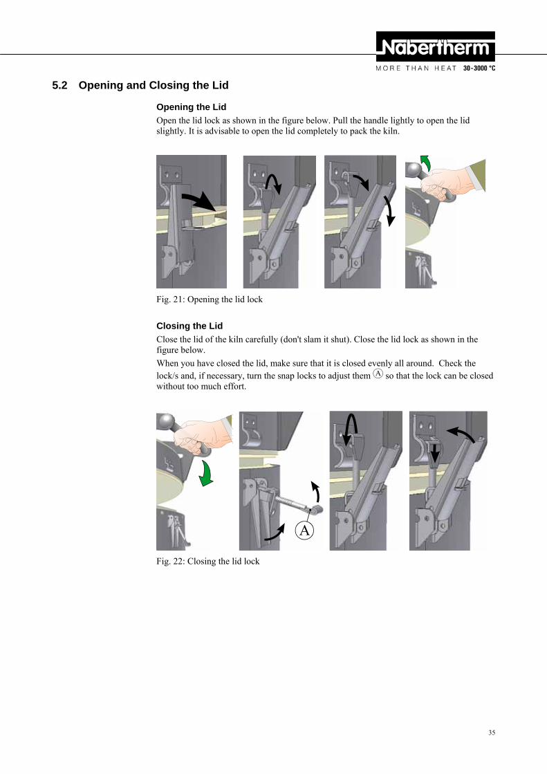
Opening the Lid
Open the lid lock as shown in the figure below. Pull the handle lightly to open the lid slightly. It is advisable to open the lid completely to pack the kiln.
Fig. 21: Opening the lid lock
Closing the Lid
Close the lid of the kiln carefully (don't slam it shut). Close the lid lock as shown in the figure below.
When you have closed the lid, make sure that it is closed evenly all around. Check the lock/s and, if necessary, turn the snap locks to adjust them A so that the lock can be closed without too much effort.
A
Fig. 22: Closing the lid lock
Pos: 129 /=== Seitenumbruch === @ 0\mod_1158819844943_0.doc @ 2983 @
36
Pos: 130 /TD/Betrieb_Bedienung/Überschrift - Zuluftschieber @ 13\mod_1289919211247_51.doc @ 108180 @ 2
5.3 Fresh Air Valve Pos: 131 /TD/Betrieb_Bedienung/Zuluftschieber Beschreibung für Top, HO und F Öfen - Text @ 13\mod_1290160012431_51.doc @ 108682 @ D
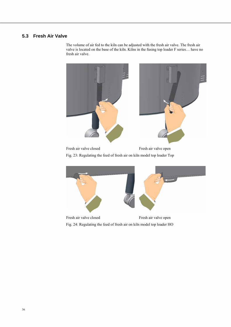
The volume of air fed to the kiln can be adjusted with the fresh air valve. The fresh air valve is located on the base of the kiln. Kilns in the fusing top loader F series… have no fresh air valve.
Pos: 132 /TD/Betrieb_Bedienung/Zuluftschieber für Top und F Öfen - Grafik @ 13\mod_1289919485230_51.doc @ 108203 @
Fresh air valve closed Fresh air valve open
Fig. 23: Regulating the feed of fresh air on kiln model top loader Top
Pos: 133 /TD/Betrieb_Bedienung/Zuluftschieber für HO - Öfen - Grafik @ 13\mod_1290159916375_51.doc @ 108659 @
Fresh air valve closed Fresh air valve open
Fig. 24: Regulating the feed of fresh air on kiln model top loader HO
Pos: 134 /=== Seitenumbruch === @ 0\mod_1158819844943_0.doc @ 2983 @
37
Pos: 135 /TD/Betrieb_Bedienung/Überschrift - Beschickung/Chargierung @ 0\mod_1167835476044_51.doc @ 5418 @ 2
5.4 Loading/charging Pos: 136 /TD/Betrieb_Bedienung/Beschickung/Chargierung Top, HO und F - Öfen @ 13\mod_1289922184571_51.doc @ 108226 @
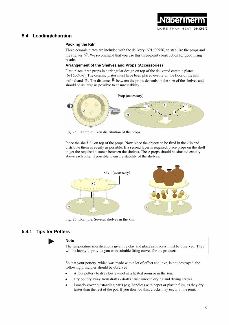
Packing the Kiln
Three ceramic plates are included with the delivery (691600956) to stabilize the props and the shelves C . We recommend that you use this three-point construction for good firing results.
Arrangement of the Shelves and Props (Accessories)
First, place three props in a triangular design on top of the delivered ceramic plates (691600956). The ceramic plates must have been placed evenly on the floor of the kiln beforehand A . The distance B between the props depends on the size of the shelves and should be as large as possible to ensure stability.
A
B
AB B
Fig. 25: Example: Even distribution of the props
Place the shelf C on top of the props. Now place the objects to be fired in the kiln and distribute them as evenly as possible. If a second layer is required, place props on the shelf to get the required distance between the shelves. These props should be situated exactly above each other if possible to ensure stability of the shelves.
C
A
C
C
A
Fig. 26: Example: Several shelves in the kiln
Pos: 137 /TD/Betrieb_Bedienung/Überschrift - Töpfer-Tipps @ 13\mod_1289996263016_51.doc @ 108345 @ 3
5.4.1 Tips for Potters Pos: 138 /TD/Betrieb_Bedienung/Hinweis - Bitte die Temperaturvorgaben der Hersteller beachten ... @ 13\mod_1291110199581_51.doc @ 109579 @
Note
The temperature specifications given by clay and glaze producers must be observed. They will be happy to provide you with suitable firing curves for the products.
Pos: 139 /TD/Betrieb_Bedienung/Brennkunde - Töpfer-Tipps - Top, HO und F - Öfen @ 13\mod_1289996369086_51.doc @ 108368 @
So that your pottery, which was made with a lot of effort and love, is not destroyed, the following principles should be observed:
Allow pottery to dry slowly – not in a heated room or in the sun.
Dry pottery away from drafts - drafts cause uneven drying and drying cracks.
Loosely cover outstanding parts (e.g. handles) with paper or plastic film, as they dry faster than the rest of the pot. If you don't do this, cracks may occur at the joint.
Prop (accessory)
Shelf (accessory)

38
Allow the pottery to dry for at least one week - longer in cool basements.
Clay shrinks when it dries; in other words, the volume is reduced due to the loss of water. Objects that stick to a surface crack when they dry - therefore, always place your pottery on fresh, clean surfaces.
Turn your pottery often as the top dries quicker than the bottom.
Handle dry pottery carefully with both hands and don't lift it by the edges. Pottery is very fragile in this state.
Pos: 140 /TD/Betrieb_Bedienung/Überschrift - Schrühbrand @ 13\mod_1289995743709_51.doc @ 108299 @ 3
5.4.2 Bisque Firing Pos: 141 /TD/Betrieb_Bedienung/Brennkunde - Schrühbrand - Top, HO und F - Öfen @ 13\mod_1289993563596_51.doc @ 108253 @
When the greenware is completely dry, it is bisque fired; that is, it is fired in the kiln at between approx. 900 °C and 950 °C. The first firing – for unglazed pottery (terracotta) the only firing – changes the physical and chemical properties of the clay. It becomes "bisque ware" (like a clay brick) and is hard and cannot be dissolved in water.
During the bisque firing the pots in the kiln can touch each other. They can be stacked (also inside each other) as long as they are not too heavy or do not prevent each other from shrinking. Tiles or flat plates should be placed directly on the shelves to prevent distortion. It really depends on the size of the objects whether they are stacked on several shelves or if a few larger pieces fill the entire kiln. But the chamber should not be "overloaded" to ensure sufficient air circulation. For the firing it is important that you know what happens to the pottery. It loses a lot of water and shrinks. If the kiln temperature is raised too quickly, the steam does not have enough time to escape and objects can crack and damage the kiln. Therefore, the kiln should be heated slowly to about 650 °C at approx. 100 °C to 150 °C per hour. Chemically bound water escapes from the clay until about this temperature. From this time you can heat the kiln to the final temperature at full power. Nabertherm controllers handle this task fully automatically.
The controller instruction manual contains all the details.
Because of the large mass and the good insulation, it takes several hours for the kiln to cool; be patient. You should open the lid a little only when the kiln has reached about 100 °C.
When the kiln is completely open, many people are amazed to find that there have been several changes to the pottery. The pieces are smaller, they are lighter in color, the clay has a different color, the bisque ware is hard and you can now lift a pot by its handle without fear of it breaking off.
Pos: 142 /TD/Betrieb_Bedienung/Überschrift - Glasurbrand @ 13\mod_1289995751005_51.doc @ 108322 @ 3
5.4.3 Glaze Firing Pos: 143 /TD/Betrieb_Bedienung/Brennkunde - Glasurbrand - Top, HO und F - Öfen @ 13\mod_1289995073443_51.doc @ 108276 @
Usually, the glaze firing is the highest temperature firing. The temperature range for earthenware (usually red or brown clay) is about 1040 °C to 1080 °C. For stoneware (usually white clay) the kiln has to reach at least 1200 °C. The glazes must be adapted to suit the temperature range.
The top of the shelves should be painted with a separating agent (batt wash) before a glaze firing. This coating should be renewed from time to time.
Check the areas where the pottery is to stand - they must be free of glaze. Pottery with a glazed base must be placed on stilts or triangular rods for the firing. Glazed pottery should be handled very carefully and should not be touched at the edges. The pots must not touch in the kiln - the glaze would fuse together (there should be a few centimeters between the pots). There must also be a gap of at least 2 cm to the heating elements.
Always use only glazes in one melting range (e.g. 1050 °C) in a firing. Heat the kiln to about 500 °C at reduced power (approx. 180 °C per hour, see also controller instructions) (water escapes from the glaze), and then heat to the final temperature at full power. Hold this temperature for about 30 minutes so that the glaze melts evenly throughout the kiln.
39
Only open the lid or door when the temperature has dropped to below 50 °C. Many glaze cracks are the result of opening the lid too soon.
You can grind any glaze drops on the bottom of the pottery or the shelves with a grinding stone or an angle grinder - paying attention to all the safety regulations.
Do not use very runny glazes to avoid damaging the shelves, the kiln insulation or the heating elements and the kiln itself.
You can obtain firing and glazing accessories and specialist literature from a specialist dealer in your neighborhood. We will be happy to provide you with addresses.
Pos: 144 /TD/Betrieb_Bedienung/Überschrift - Reduzierender Brand (Keramikanwendung) @ 13\mod_1290679508265_51.doc @ 109389 @ 3
5.4.4 Reduction Firing Pos: 145 /TD/Betrieb_Bedienung/Brennkunde - Reduzierender Brand - Top, HO und F - Öfen @ 13\mod_1290679415421_51.doc @ 109366 @
In a reduction firing, oxygen in the kiln is consumed by means of a foreign substance. However, since oxygen is needed to maintain the protective oxide layer on the heating elements NO reduction firings should be carried out in an electrically heated kiln. Under certain circumstances, high concentrations of gases can settle in the insulation and destroy it. If it is unavoidable, after each reduction firing the kiln must be fired with a normal atmosphere to replace the protective oxide layer on the heating elements. No warranty claims will be accepted for damage caused by reduction firings.
Pos: 146 /=== Seitenumbruch === @ 0\mod_1158819844943_0.doc @ 2983 @ Pos: 147 /TD/Wartung_Reinigung_Instandhaltung/Überschrift - Wartung, Reinigung und Instandhaltung @ 0\mod_1167835785730_51.doc @ 5436 @ 1
6 Servicing, Cleaning, and Maintenance Pos: 148 /TD/Wartung_Reinigung_Instandhaltung/Überschrift - Stillsetzung der Anlage bei Wartung, Reinigung und Instandhaltung @ 10\mod_1252576898142_51.doc @ 65883 @ 2
6.1 Shutting Down the Oven for Servicing, Cleaning, and Maintenance Pos: 149 /TD/Wartung_Reinigung_Instandhaltung/Stillsetzung der Anlage für Wartungsarbeiten - Top, HO und F - Öfen @ 13\mod_1290009871262_51.doc @ 108437 @
Risks during normal operation
Repairs and maintenance work must be performed by authorized persons, following the maintenance instructions and the accident prevention regulations. We recommend that the maintenance and repair work be carried out by the service team of Nabertherm GmbH. Non-compliance may cause injuries, death, or considerable damage to property.
Operators may only rectify faults that are obviously due to operating errors.
Wait until the kiln and the connected parts have cooled to room temperature.
The kiln must be completely empty.
Switch off the main switch and pull out the power plug.
Risks during normal operation
Do not touch any objects without first checking how hot they are.
Pos: 150 /TD/Allgemeine Hinweise (für alle Anleitungen)/Hinweis - Dieser Ofen enthält in der Isolierung keramisches Fasermaterial - Toplader-Top @ 13\mod_1290673657059_51.doc @ 109343 @
Kilns in the top loader series Top 16/R, Top 45 and Top 60 have ceramic fiber material in their insulation.
In the Federal Republic of Germany, active handling of these fibers (e.g. replacing the insulation) is subject to the regulations of the German Hazardous Substances Ordinance, Annex V No. 7 "Artificial Mineral Fibers" from June 12, 1998. In the rest of the European Union, ceramic fibers are classified according to Commission Directive 97/69/EC from December 5, 1997 as follows: CARC. Cat. 2; R 49; Xi R 38. Work with fiber insulation
40
should be carried out so that as little fiber dust as possible is released.
The following points should be observed when working with ceramic fiber:
- Keep dust to a minimum. - Avoid contact with skin and eyes. The effects of fibers in the eyes can cause mechanical irritation, which can, in turn cause redness and itching. - When working with large quantities of ceramic fiber, wear loose working clothes with long sleeves, gloves, and protective eyewear. - When working inside kilns with ceramic fiber insulation, you should also wear a half/quarter mask with P2 filter
Commercial use: The kiln and its equipment must be checked regularly according to the national regulations in the country in which they are installed.
Pos: 151 /TD/Ersatz-/Verschleißteile/Warnung - Gefahren durch elektrischen Strom - für alle Öfen @ 3\mod_1189491390787_51.doc @ 21273 @
Warning - Danger of Electric Shock!
Work on the electrical equipment may be done only by qualified, authorized electricians. During maintenance work it must be ensured that the oven and the switching equipment cannot be activated by mistake (pull out the power plug) and that all moving parts in the oven are secured. Observe BGV A3 or the corresponding national regulations in the country where the oven is installed. Wait until the oven and the connected parts have cooled to room temperature.
Pos: 152 /=== Seitenumbruch === @ 0\mod_1158819844943_0.doc @ 2983 @
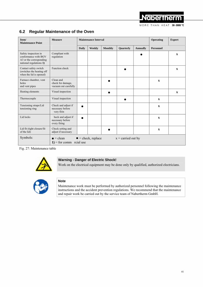
41
Pos: 153 /TD/Wartung_Reinigung_Instandhaltung/Überschrift - Regelmäßige Wartungsarbeiten am Ofen @ 0\mod_1167836306681_51.doc @ 5463 @ 2
6.2 Regular Maintenance of the Oven Pos: 154 /TD/Wartung_Reinigung_Instandhaltung/Regelmäßige Wartungsarbeiten (Wartungstabelle) am Top, HO und F - Ofen @ 13\mod_1290007762347_51.doc @ 108414 @
Item/ Maintenance Point
Measure Maintenance Interval Operating Expert
Daily Weekly Monthly Quarterly Annually Personnel
Safety inspection in conformance with BGV A3 or the corresponding national regulations 1)
Compliant with regulation
● x
Contact safety switch (switches the heating off when the lid is opened)
Function check ● x
Furnace chamber, vent holes and vent pipes
Clean and check for damage, vacuum out carefully
● x
Heating elements Visual inspection ● x
Thermocouple Visual inspection ● x
Tensioning straps/Lid tensioning ring
Check and adjust if necessary before very firin
● x
Lid locks heck and adjust if necessary before every firing
● x
Lid fit (tight closure/fit of the lid)
Check setting and adjust if necessary
● x
Symbols: ■ = clean ● = check, replace x = carried out by 1) = for comm rcial use
Fig. 27: Maintenance table
Pos: 155 /TD/Allgemeine Hinweise (für alle Anleitungen)/Warnung - Arbeiten an der elektrischen Ausrüstung dürfen nur von ... @ 2\mod_1184228021019_51.doc @ 19673 @
Warning - Danger of Electric Shock!
Work on the electrical equipment may be done only by qualified, authorized electricians.
Pos: 156 /TD/Allgemeine Hinweise (für alle Anleitungen)/Hinweis - Wartungsarbeiten dürfen nur von autorisierten Fachpersonen unter Beachtung von ... @ 1\mod_1173971704689_51.doc @ 11131 @
Note
Maintenance work must be performed by authorized personnel following the maintenance instructions and the accident prevention regulations. We recommend that the maintenance and repair work be carried out by the service team of Nabertherm GmbH.
Pos: 157 /=== Seitenumbruch === @ 0\mod_1158819844943_0.doc @ 2983 @
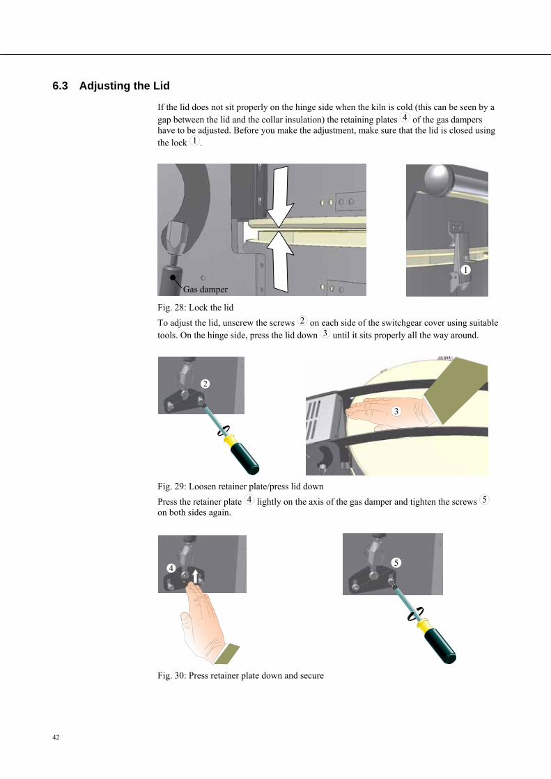
42
Pos: 158 /TD/Wartung_Reinigung_Instandhaltung/Überschrift - Einstellung des Deckels @ 13\mod_1290155736884_51.doc @ 108567 @ 2
6.3 Adjusting the Lid Pos: 159 /TD/Wartung_Reinigung_Instandhaltung/Einstellung des Deckels für Top und F Öfen @ 13\mod_1290158796188_51.doc @ 108613 @ D
If the lid does not sit properly on the hinge side when the kiln is cold (this can be seen by a gap between the lid and the collar insulation) the retaining plates 4 of the gas dampers have to be adjusted. Before you make the adjustment, make sure that the lid is closed using the lock 1 .
1
Fig. 28: Lock the lid
To adjust the lid, unscrew the screws 2 on each side of the switchgear cover using suitable tools. On the hinge side, press the lid down 3 until it sits properly all the way around.
2
3
Fig. 29: Loosen retainer plate/press lid down
Press the retainer plate 4 lightly on the axis of the gas damper and tighten the screws 5 on both sides again.
4
5
Fig. 30: Press retainer plate down and secure Pos: 160 /=== Seitenumbruch === @ 0\mod_1158819844943_0.doc @ 2983 @
Gas damper
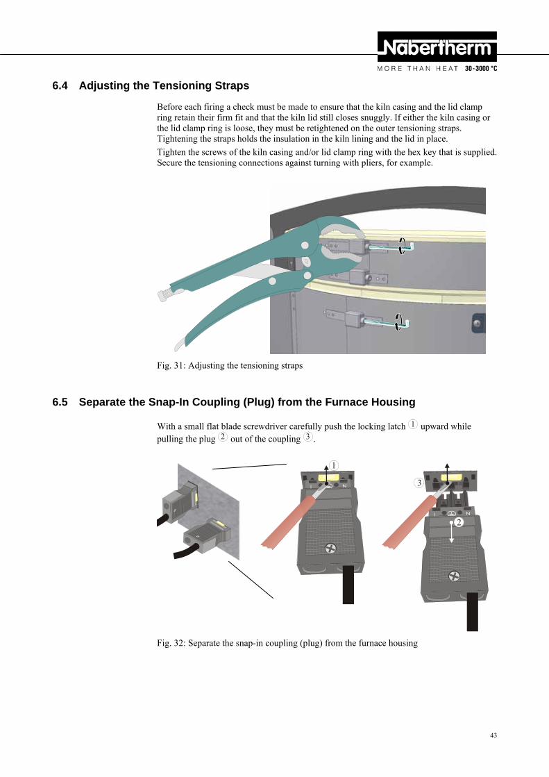
43
Pos: 161 /TD/Wartung_Reinigung_Instandhaltung/Überschrift - Nachstellen der Spannbänder @ 13\mod_1290155781920_51.doc @ 108590 @ 2
6.4 Adjusting the Tensioning Straps Pos: 162 /TD/Wartung_Reinigung_Instandhaltung/Nachstellen der Spannbänder für Top und F Öfen @ 13\mod_1290159806808_51.doc @ 108636 @ D
Before each firing a check must be made to ensure that the kiln casing and the lid clamp ring retain their firm fit and that the kiln lid still closes snuggly. If either the kiln casing or the lid clamp ring is loose, they must be retightened on the outer tensioning straps. Tightening the straps holds the insulation in the kiln lining and the lid in place.
Tighten the screws of the kiln casing and/or lid clamp ring with the hex key that is supplied. Secure the tensioning connections against turning with pliers, for example.
Fig. 31: Adjusting the tensioning straps
Pos: 163 /=== Seitenumbruch === @ 0\mod_1158819844943_0.doc @ 2983 @ Pos: 164 /TD/Betrieb_Bedienung/Überschrift - Snap-In-Kupplung (Stecker) vom Ofengehäuse trennen 1.1 @ 12\mod_1282113872192_51.doc @ 96923 @ 2
6.5 Separate the Snap-In Coupling (Plug) from the Furnace Housing Pos: 165 /TD/Betrieb_Bedienung/Bedienung Snap-In-Kupplung (Stecker) vom Ofengehäuse trennen @ 12\mod_1282114156861_51.doc @ 96945 @
With a small flat blade screwdriver carefully push the locking latch 1 upward while pulling the plug 2 out of the coupling 3 .
1
3
2
Fig. 32: Separate the snap-in coupling (plug) from the furnace housing
Pos: 166 /=== Seitenumbruch === @ 0\mod_1158819844943_0.doc @ 2983 @
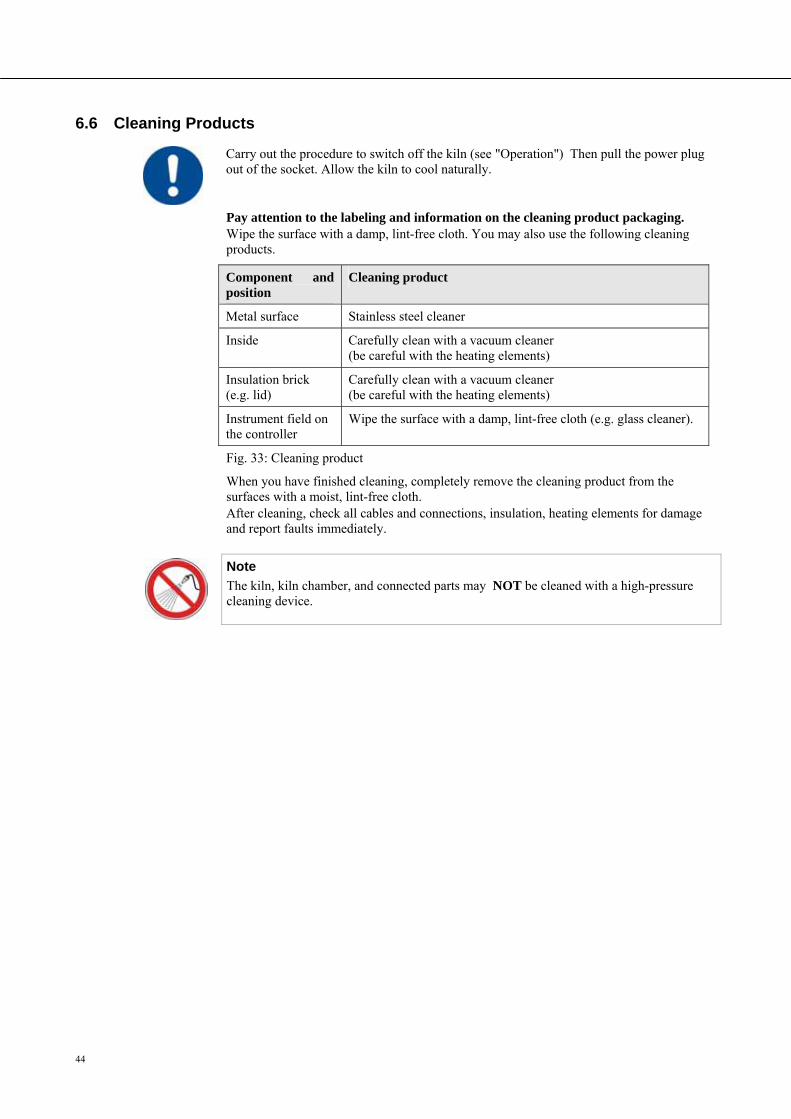
44
Pos: 167 /TD/Wartung_Reinigung_Instandhaltung/Überschrift - Reinigungsmittel 1.1 @ 0\mod_1167837229988_51.doc @ 5508 @ 2
6.6 Cleaning Products Pos: 168 /TD/Wartung_Reinigung_Instandhaltung/Reinigung Top, HO und F - Öfen @ 13\mod_1290006673176_51.doc @ 108391 @
Carry out the procedure to switch off the kiln (see "Operation") Then pull the power plug out of the socket. Allow the kiln to cool naturally.
Pay attention to the labeling and information on the cleaning product packaging. Wipe the surface with a damp, lint-free cloth. You may also use the following cleaning products.
Component and position
Cleaning product
Metal surface Stainless steel cleaner
Inside Carefully clean with a vacuum cleaner (be careful with the heating elements)
Insulation brick (e.g. lid)
Carefully clean with a vacuum cleaner (be careful with the heating elements)
Instrument field on the controller
Wipe the surface with a damp, lint-free cloth (e.g. glass cleaner).
Fig. 33: Cleaning product
When you have finished cleaning, completely remove the cleaning product from the surfaces with a moist, lint-free cloth. After cleaning, check all cables and connections, insulation, heating elements for damage and report faults immediately.
Note
The kiln, kiln chamber, and connected parts may NOT be cleaned with a high-pressure cleaning device.
Pos: 169 /=== Seitenumbruch === @ 0\mod_1158819844943_0.doc @ 2983 @
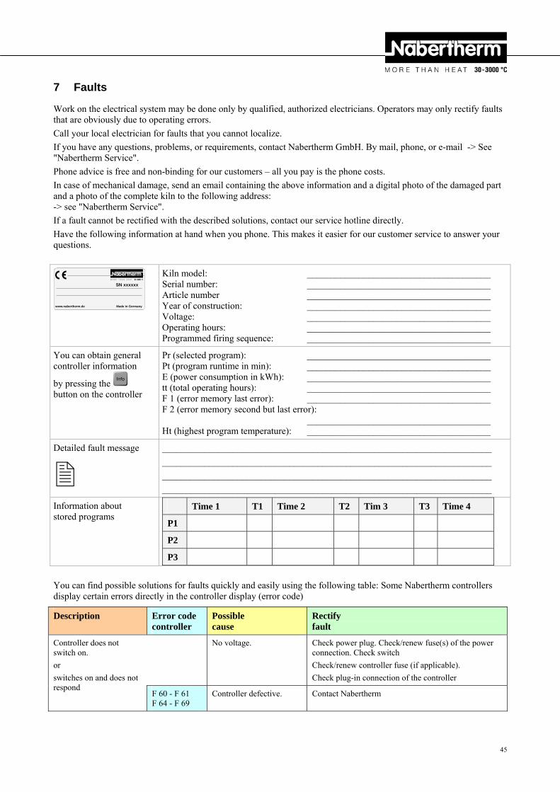
45
Pos: 170 /TD/Störungen/Fehlersuche/Öfen/Überschrift - Störungen @ 0\mod_1167837724781_51.doc @ 5526 @ 1
7 Faults Pos: 171 /TD/Störungen/Fehlersuche/Öfen/Störungstabelle Ofen Top, HO und F - Öfen (allgemeine Hinweise) @ 13\mod_1290088597741_51.doc @ 108533 @
Work on the electrical system may be done only by qualified, authorized electricians. Operators may only rectify faults that are obviously due to operating errors.
Call your local electrician for faults that you cannot localize.
If you have any questions, problems, or requirements, contact Nabertherm GmbH. By mail, phone, or e-mail -> See "Nabertherm Service".
Phone advice is free and non-binding for our customers – all you pay is the phone costs.
In case of mechanical damage, send an email containing the above information and a digital photo of the damaged part and a photo of the complete kiln to the following address: -> see "Nabertherm Service".
If a fault cannot be rectified with the described solutions, contact our service hotline directly.
Have the following information at hand when you phone. This makes it easier for our customer service to answer your questions.
www.nabertherm.de Made in Germany
SN xxxxxx
Kiln model: _______________________________________ Serial number: _______________________________________ Article number _______________________________________ Year of construction: _______________________________________ Voltage: _______________________________________ Operating hours: _______________________________________ Programmed firing sequence: _______________________________________
You can obtain general controller information
by pressing the button on the controller
Pr (selected program): _______________________________________ Pt (program runtime in min): _______________________________________ E (power consumption in kWh): _______________________________________ tt (total operating hours): _______________________________________ F 1 (error memory last error): _______________________________________ F 2 (error memory second but last error): _______________________________________ Ht (highest program temperature): _______________________________________
Detailed fault message
______________________________________________________________________
______________________________________________________________________
______________________________________________________________________
______________________________________________________________________
Information about stored programs
Time 1 T1 Time 2 T2 Tim 3 T3 Time 4
P1
P2
P3
You can find possible solutions for faults quickly and easily using the following table: Some Nabertherm controllers display certain errors directly in the controller display (error code) Pos: 172 /TD/Störungen/Fehlersuche/Öfen/Störungstabelle Top, HO und F - Öfen @ 13\mod_1290076726114_51.doc @ 108516 @
Description Error code controller
Possible cause
Rectify fault
Controller does not switch on.
or
switches on and does not respond
No voltage. Check power plug. Check/renew fuse(s) of the power connection. Check switch
Check/renew controller fuse (if applicable).
Check plug-in connection of the controller
F 60 - F 61 F 64 - F 69
Controller defective. Contact Nabertherm
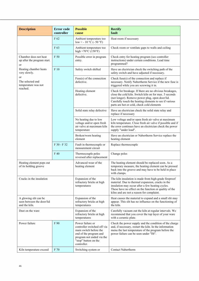
46
Description Error code controller
Possible cause
Rectify fault
F 62 Ambient temperature too low < - 10 °C (- 50 °F)
Heat room if necessary
F 63 Ambient temperature too high >70°C (158°F)
Check room or ventilate gaps to walls and ceiling
Chamber does not heat up after the program start.
or
Heating chamber heats very slowly.
or
The selected end temperature was not reached.
F 50 Possible error in program entry.
Check entry for heating program (see controller instructions) under certain conditions. Lead time programmed?
F 10 Safety switch shifted Have an electrician check the switching path of the safety switch and have adjusted if necessary.
Fuse(s) of the connection defective.
Check fuse(s) of the connection and replace if necessary. Notify Nabertherm Service if the new fuse is triggered while you are screwing it in.
Heating element defective.
Check for breakage. If there are no obvious breakages, close the cold kiln. Switch kiln on for max. 5 seconds (not longer). Remove power plug, open door/lid. Carefully touch the heating elements to see if various parts are hot or cold, check cold elements
Solid state relay defective Have an electrician check the solid state relay and replace if necessary
No heating due to low voltage and/or open fresh air valve at maximum kiln temperature
Low voltage and/or open fresh air valve at maximum kiln temperature. Close fresh air valve if possible and if the error continues have an electrician check the power supply "under load".
Broken/worn heating element
Have an electrician or Nabertherm Service replace the heating element
F 30 - F 32 Fault in thermocouple or measurement circuit
Replace thermocouple
F 40 Thermocouple poles reversed after replacement
Change poles
Heating element pops out of its holding groove
Advanced wear of the heating element
The heating element should be replaced soon. As a temporary measure, the heating element can be pressed back into the groove and may have to be held in place with clamps.
Cracks in the insulation Expansion of the refractory bricks at high temperatures
The kiln insulation is made from high-grade fireproof material. Due to thermal expansion, cracks in the insulation may occur after a few heating cycles. These have no effect on the function or quality of the kilns and are not a reason for complaint.
A glowing slit can be seen between the door/lid and the kiln.
Expansion of the refractory bricks at high temperatures
Heat causes the material to expand and a small slit may appear. This slit has no influence on the functioning of the kiln.
Dust on the ware Expansion of the refractory bricks at high temperatures
Carefully vacuum out the kiln at regular intervals. We recommend that you cover the top layer of your ware with a ceramic plate.
Power failure F 90 Power failure or controller switched off via main switch before the end of the program and program not ended via the "stop" button on the controller.
Check the power supply and the condition of the charge and, if necessary, restart the kiln. In the information menu the last temperature of the program before the power failure can be seen under "Ht".
Kiln temperature exceed F 70 Switching system or Contact Nabertherm
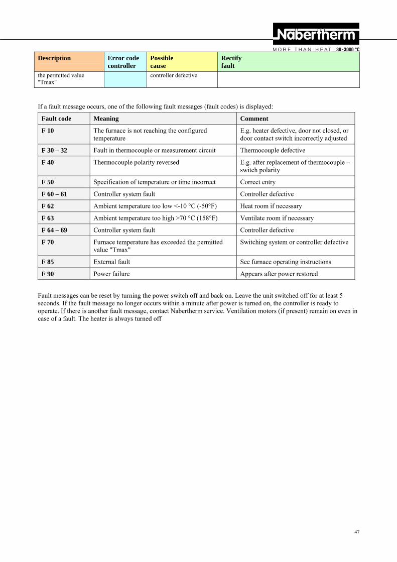
47
Description Error code controller
Possible cause
Rectify fault
the permitted value "Tmax"
controller defective
Pos: 173 /TD/Störungen/Fehlersuche/Controller/B150/B130/B170/C280/C290/C295/P320/Fehlermeldungen Controller @ 0\mod_1168954407482_51.doc @ 6642 @
If a fault message occurs, one of the following fault messages (fault codes) is displayed:
Fault code Meaning Comment
F 10 The furnace is not reaching the configured temperature
E.g. heater defective, door not closed, or door contact switch incorrectly adjusted
F 30 – 32 Fault in thermocouple or measurement circuit Thermocouple defective
F 40 Thermocouple polarity reversed E.g. after replacement of thermocouple – switch polarity
F 50 Specification of temperature or time incorrect Correct entry
F 60 – 61 Controller system fault Controller defective
F 62 Ambient temperature too low <-10 °C (-50°F) Heat room if necessary
F 63 Ambient temperature too high >70 °C (158°F) Ventilate room if necessary
F 64 – 69 Controller system fault Controller defective
F 70 Furnace temperature has exceeded the permitted value "Tmax"
Switching system or controller defective
F 85 External fault See furnace operating instructions
F 90 Power failure Appears after power restored
Fault messages can be reset by turning the power switch off and back on. Leave the unit switched off for at least 5 seconds. If the fault message no longer occurs within a minute after power is turned on, the controller is ready to operate. If there is another fault message, contact Nabertherm service. Ventilation motors (if present) remain on even in case of a fault. The heater is always turned off
Pos: 174 /=== Seitenumbruch === @ 0\mod_1158819844943_0.doc @ 2983 @
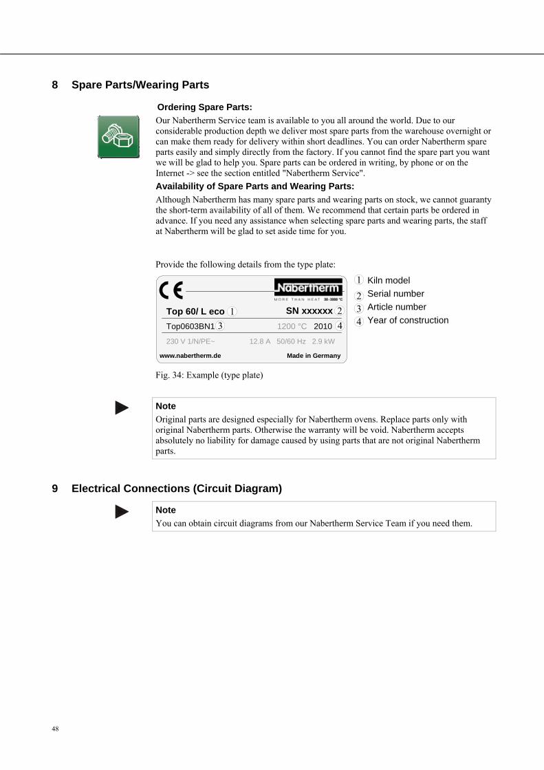
48
Pos: 175 /TD/Ersatz-/Verschleißteile/Überschrift - Ersatz-/Verschleißteile @ 0\mod_1164125252056_51.doc @ 4243 @ 1
8 Spare Parts/Wearing Parts Pos: 176 /TD/Ersatz-/Verschleißteile/Ersatz-/Verschleißteile allgemeiner Text für alle Öfen ohne Spezifizierung der Teile @ 13\mod_1290428577708_51.doc @ 108720 @
Ordering Spare Parts:
Our Nabertherm Service team is available to you all around the world. Due to our considerable production depth we deliver most spare parts from the warehouse overnight or can make them ready for delivery within short deadlines. You can order Nabertherm spare parts easily and simply directly from the factory. If you cannot find the spare part you want we will be glad to help you. Spare parts can be ordered in writing, by phone or on the Internet -> see the section entitled "Nabertherm Service".
Availability of Spare Parts and Wearing Parts:
Although Nabertherm has many spare parts and wearing parts on stock, we cannot guaranty the short-term availability of all of them. We recommend that certain parts be ordered in advance. If you need any assistance when selecting spare parts and wearing parts, the staff at Nabertherm will be glad to set aside time for you.
Pos: 177 /TD/Ersatz-/Verschleißteile/Ersatz-/Verschleißteile Typenschild Top, HO und F @ 13\mod_1290430968115_51.doc @ 108743 @
Provide the following details from the type plate:
www.nabertherm.de Made in Germany
SN xxxxxx
Kiln model
Serial number
Article number
Year of construction
Fig. 34: Example (type plate)
Pos: 178 /TD/Ersatz-/Verschleißteile/Hinweis - Originalteile und Zubehör sind speziell für Nabertherm-Ofenanlagen ... @ 8\mod_1242719812994_51.doc @ 56963 @
Note
Original parts are designed especially for Nabertherm ovens. Replace parts only with original Nabertherm parts. Otherwise the warranty will be void. Nabertherm accepts absolutely no liability for damage caused by using parts that are not original Nabertherm parts.
Pos: 179 /=== Seitenumbruch === @ 0\mod_1158819844943_0.doc @ 2983 @
9 Electrical Connections (Circuit Diagram) Pos: 200 /TD/Betrieb_Bedienung/Controller/B150/B130/B170/C280/C290/C295/P320/Schaltpläne/Schaltpläne können bei Bedarf bei unserem Nabertherm-Service angefordert werden. @ 14\mod_1295363844110_51.doc @ 111883 @
Note
You can obtain circuit diagrams from our Nabertherm Service Team if you need them.
Pos: 201 /TD/Ersatz-/Verschleißteile/Ersatz-/Verschleißteile Typenschild Top, HO und F @ 13\mod_1290430968115_51.doc @ 108743 @
Top0603BN1 1200 °C 2010
Top 60/ L eco
230 V 1/N/PE~ 12.8 A 50/60 Hz 2.9 kW
1
1
2
3 4
234
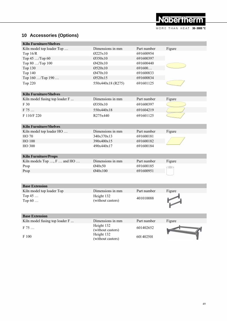
49
Pos: 180 /TD/Zubehör/Überschrift - Zubehör (Optionen) @ 2\mod_1184078674990_51.doc @ 19536 @ 1
10 Accessories (Options) Pos: 181 /TD/Zubehör/Zubehör Einbauplatten Toplader Top @ 13\mod_1290442149493_51.doc @ 108812 @
Kiln Furniture/ShelvesKiln model top loader Top … Dimensions in mm Part number Figure Top 16/R Ø225x10 691600954
Top 45 …/Top 60 Ø350x10 691600397Top 80 …/Top 100 Ø420x10 691600440Top 130 Ø520x10 691600…Top 140 Ø470x10 691600833Top 160 …/Top 190 … Ø520x15 691600834Top 220 550x440x18 (R275) 691601125
Pos: 182 /TD/Zubehör/Zubehör Einbauplatten Fusing-Toplader F @ 13\mod_1290517307329_51.doc @ 108843 @
Kiln Furniture/ShelvesKiln model fusing top loader F ... Dimensions in mm Part number Figure
F 30 Ø350x10 691600397 F 75 … 550x440x18 691604219 F 110/F 220 R275x440 691601125
Pos: 183 /TD/Zubehör/Zubehör Einbauplatten Toplader HO @ 13\mod_1290517368096_51.doc @ 108866 @
Kiln Furniture/ShelvesKiln model top loader HO … Dimensions in mm Part number Figure HO 70 340x370x13 691600181
HO 100 390x400x15 691600182HO 300 490x440x17 691600184
Pos: 184 /TD/Zubehör/Zubehör Einbaustützen Toplader Top,F und HO @ 13\mod_1290519056528_51.doc @ 108889 @
Kiln Furniture/PropsKiln models Top …, F … and HO … Dimensions in mm Part number Figure Prop Ø40x50 691600185
Prop Ø40x100 691600951
Pos: 185 /TD/Zubehör/Zubehör Untergestellerhöhung Toplader Top 45 und Top 60 @ 13\mod_1290609013082_51.doc @ 109268 @
Base ExtensionKiln model top loader Top Dimensions in mm Part number Figure Top 45 … Height 132
(without castors) 401010088
Top 60 …
Pos: 186 /TD/Zubehör/Zubehör Untergestellerhöhung Fusing-Toplader F 75 und F 110 @ 13\mod_1290609439574_51.doc @ 109291 @
Base ExtensionKiln model fusing top loader F ... Dimensions in mm Part number Figure
F 75 … Height 132 (without castors)
601402652
F 100 Height 132 (without castors)
Pos: 187 /=== Seitenumbruch === @ 0\mod_1158819844943_0.doc @ 2983 @
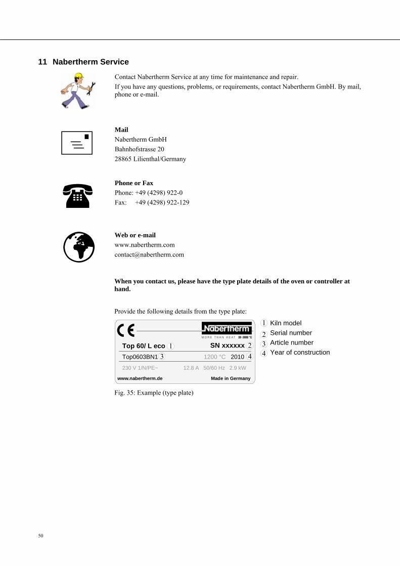
50
Pos: 188 /TD/Service/Nabertherm-Service @ 0\mod_1158658915997_51.doc @ 2861 @ 1
11 Nabertherm Service
Contact Nabertherm Service at any time for maintenance and repair.
If you have any questions, problems, or requirements, contact Nabertherm GmbH. By mail, phone or e-mail.
Nabertherm GmbH
Bahnhofstrasse 20
28865 Lilienthal/Germany
Phone or Fax
Phone: +49 (4298) 922-0
Fax: +49 (4298) 922-129
Web or e-mail
www.nabertherm.com
When you contact us, please have the type plate details of the oven or controller at hand.
Pos: 189 /TD/Ersatz-/Verschleißteile/Ersatz-/Verschleißteile Typenschild Top, HO und F @ 13\mod_1290430968115_51.doc @ 108743 @
Provide the following details from the type plate:
www.nabertherm.de Made in Germany
SN xxxxxx
Kiln model
Serial number
Article number
Year of construction
Fig. 35: Example (type plate)
Pos: 190 /=== Seitenumbruch === @ 0\mod_1158819844943_0.doc @ 2983 @
Top0603BN1 1200 °C 2010
Top 60/ L eco
230 V 1/N/PE~ 12.8 A 50/60 Hz 2.9 kW
1
1
2
3 4
234
51
Pos: 191 /TD/Außerbetriebnahme_Demontage_Lagerung_Rücktransport/Überschrift - Außerbetriebnahme, Demontage und Lagerung @ 0\mod_1167838295210_51.doc @ 5580 @ 1
12 Shut-Down, Dismantling, and Storage Pos: 192 /TD/Sicherheit/Überschrift - Umweltschutzvorschriften @ 0\mod_1167826189237_51.doc @ 5202 @ 2
12.1 Environmental Regulations Pos: 193 /TD/Sicherheit/Umweltschutzvorschriften Elektronische Bauteile-Isolierung-Altmetall @ 4\mod_1205143314853_51.doc @ 32563 @
When it is delivered, this oven contains no substances that make a hazardous waste classification necessary. However, residues of process materials may accumulate in the oven insulation during operation. These may be hazardous to health and/or the environment.
Dismantle the electronic components and dispose of them as electric scrap.
Remove the insulation and dispose of it as hazardous waste (See Servicing, Cleaning, and Maintenance with Ceramic Fiber Material)
Dispose of the housing as scrap metal.
Pos: 194 /TD/Außerbetriebnahme_Demontage_Lagerung_Rücktransport/Hinweis - Deckelverschluss am Ofendeckel zerstören. Sie verhinder dadurch, dass Kinder ... @ 13\mod_1290683822320_51.doc @ 109481 @
Safety information:
When the kiln is being disposed of, the lid lock should be destroyed. This stops children being locked in and facing the risk of death.
Separate the power cable and dispose of this together with the plug.
Pos: 195 /TD/Allgemeine Hinweise (für alle Anleitungen)/Hinweis - Nationalen Vorschriften des jeweiligen Verwendungslandes sind zu beachten. @ 10\mod_1258644986266_51.doc @ 68881 @
Note
Observe the national regulations of the country in which the kiln will be used.
Pos: 196 /=== Seitenumbruch === @ 0\mod_1158819844943_0.doc @ 2983 @
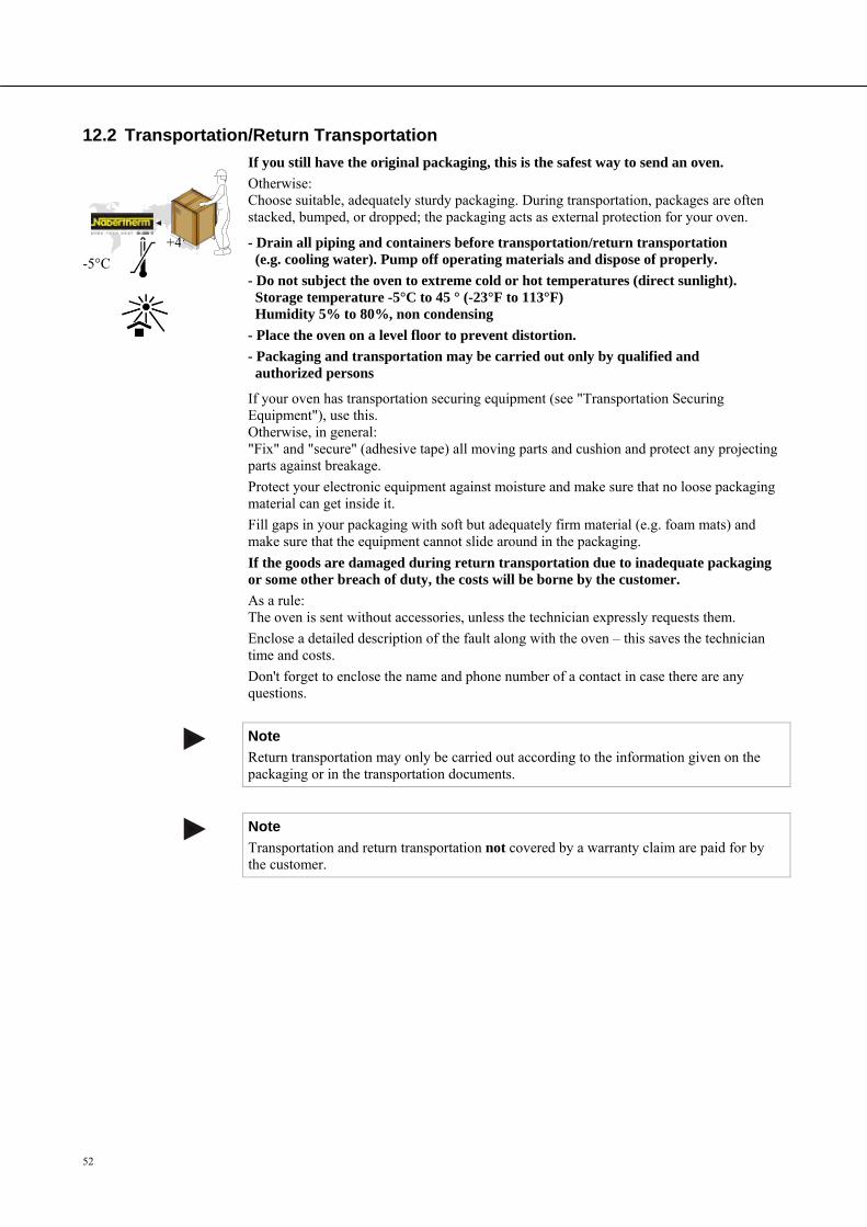
52
Pos: 197 /TD/Außerbetriebnahme_Demontage_Lagerung_Rücktransport/Hinweise für den Rücktransport der Ofen-Anlage @ 4\mod_1202459053863_51.doc @ 30918 @ 2
12.2 Transportation/Return Transportation
If you still have the original packaging, this is the safest way to send an oven.
Otherwise: Choose suitable, adequately sturdy packaging. During transportation, packages are often stacked, bumped, or dropped; the packaging acts as external protection for your oven.
+45�
-5°C
- Drain all piping and containers before transportation/return transportation (e.g. cooling water). Pump off operating materials and dispose of properly.
- Do not subject the oven to extreme cold or hot temperatures (direct sunlight). Storage temperature -5°C to 45 ° (-23°F to 113°F) Humidity 5% to 80%, non condensing
- Place the oven on a level floor to prevent distortion.
- Packaging and transportation may be carried out only by qualified and authorized persons
If your oven has transportation securing equipment (see "Transportation Securing Equipment"), use this. Otherwise, in general: "Fix" and "secure" (adhesive tape) all moving parts and cushion and protect any projecting parts against breakage.
Protect your electronic equipment against moisture and make sure that no loose packaging material can get inside it.
Fill gaps in your packaging with soft but adequately firm material (e.g. foam mats) and make sure that the equipment cannot slide around in the packaging.
If the goods are damaged during return transportation due to inadequate packaging or some other breach of duty, the costs will be borne by the customer.
As a rule: The oven is sent without accessories, unless the technician expressly requests them.
Enclose a detailed description of the fault along with the oven – this saves the technician time and costs.
Don't forget to enclose the name and phone number of a contact in case there are any questions.
Note
Return transportation may only be carried out according to the information given on the packaging or in the transportation documents.
Note
Transportation and return transportation not covered by a warranty claim are paid for by the customer.
Pos: 198 /=== Seitenumbruch === @ 0\mod_1158819844943_0.doc @ 2983 @
53
Pos: 199 /TD/Betrieb_Bedienung/Controller/B150/B130/B170/C280/C290/C295/P320/Schaltpläne/Überschrift - Elektrischer Anschluss (Schaltplan) @ 0\mod_1169476874919_51.doc @ 7492 @ 1 Pos: 204 /TD/Anhang/Überschrift - Konformitätserklärung @ 2\mod_1186581095030_51.doc @ 20795 @ 1
13 Declaration of Conformity Pos: 205 /EG-Erklärungen/Kopfmodul/Konformitätserklärung Niederspannungsrichtlinie 2006/95/EG @ 9\mod_1245848340236_51.doc @ 61263 @
EC Declaration of Conformity in accordance with EC directives 2006/95/EEC and
EMC directive 2004/108/EEC
Hereby
Nabertherm GmbH Bahnhofstr. 20, 28865 Lilienthal, Germany
Pos: 206 /EG-Erklärungen/Gültigkeitsbereiche/Gültigkeitsbereichstext Produkt - Allgemein @ 0\mod_1154932375002_51.doc @ 903 @
declares that the product specified below conforms to the relevant fundamental safety and health requirements of the appropriate EU Directive both in its basic design and construction as well as in the version marketed by us. The declaration will cease to be valid if any modifications are made to the machine without our approval.
Pos: 207 /EG-Erklärungen/Produktangaben/Modelle TOP, HO und F für die Betriebsanleitung @ 13\mod_1289805400331_51.doc @ 107827 @ 1
Electrically heated kiln
Model Top 16/R Top 45 Top 45eco Top 60 Top 60/R
Top 60eco Top 60/Leco Top 80 Top 100 Top 130
Top 140 Top 160 Top 190 Top 220
HO 70/L HO 70/R HO 100 HO 300
F 30 F 75L F 75 F 110 F 220
For all kilns with switchgear and controller Pos: 208.1 /EG-Erklärungen/Mitgeltende Normen/Folgende harmonisierte Normen wurden angewandt: @ 10\mod_1260360041778_51.doc @ 69544 @
The following harmonized standards were applied: Pos: 208.2 /EG-Erklärungen/Mitgeltende Normen/Normen/DIN EN 60335-1 @ 14\mod_1291814199588_0.doc @ 110103 @
DIN EN 60335-1 (11.2010) Pos: 208.3 /EG-Erklärungen/Mitgeltende Normen/Normen/DIN EN 61000-6-1, DIN EN 61000-6-3 @ 10\mod_1260454484148_0.doc @ 69791 @
DIN EN 61000-6-1 (10.2007) , DIN EN 61000-6-3 (09.2007) Pos: 209 /EG-Erklärungen/Ort und Datum @ 0\mod_1155018513651_0.doc @ 1093 @
Lilienthal, 07.05.2010 Pos: 210 /EG-Erklärungen/Unterschriftkombinationen/Unterschriften Adamek/Bartilla mit Unterschrift @ 0\mod_1157379942170_51.doc @ 1193 @
________________________ _______________________
Thomas Adamek Wolfgang Bartilla Quality Management Research and Development
Pos: 211 /=== Seitenumbruch === @ 0\mod_1158819844943_0.doc @ 2983 @

54
Pos: 212 /TD/Notizen/Für Ihre Notizen @ 0\mod_1157544056930_51.doc @ 1725 @ 1
14 For Your Notes
=== Ende der Liste für Textmarke Inhalt ===

55

Headquarters: Reg: M01.0029 ENGLISCH Nabertherm GmbH . Bahnhofstr. 20 . 28865 Lilienthal/Bremen, Germany . Tel +49 (4298) 922-0, Fax -129 . [email protected] . www.nabertherm.com


![W€RLD CEt|E]If Cement Feb 1997... · the kiln top into a distributing and double sea ... more without receiving any maintenance. After four months of kiln operation by SIC ... ON](https://img.pdfslide.us/doc/110x75/5ac0f3617f8b9ae45b8ccb4b/wrld-ceteif-cement-feb-1997the-kiln-top-into-a-distributing-and-double-sea.jpg)