Embed Size (px)
Citation preview

MAKING MODERN LIVING POSSIBLE
Operating InstructionsVLT® AutomationDrive FC 301/3020.25-75 kW
vlt-drives.danfoss.com

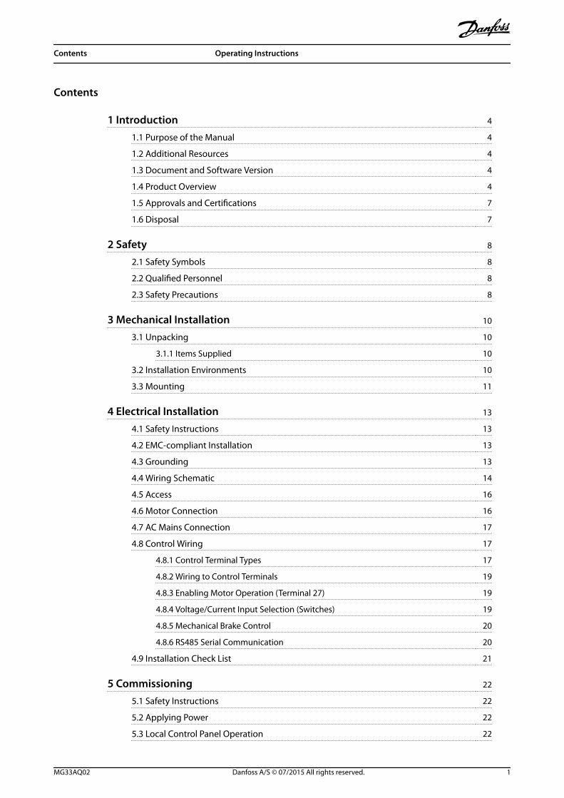
Contents
1 Introduction 4
1.1 Purpose of the Manual 4
1.2 Additional Resources 4
1.3 Document and Software Version 4
1.4 Product Overview 4
1.5 Approvals and Certifications 7
1.6 Disposal 7
2 Safety 8
2.1 Safety Symbols 8
2.2 Qualified Personnel 8
2.3 Safety Precautions 8
3 Mechanical Installation 10
3.1 Unpacking 10
3.1.1 Items Supplied 10
3.2 Installation Environments 10
3.3 Mounting 11
4 Electrical Installation 13
4.1 Safety Instructions 13
4.2 EMC-compliant Installation 13
4.3 Grounding 13
4.4 Wiring Schematic 14
4.5 Access 16
4.6 Motor Connection 16
4.7 AC Mains Connection 17
4.8 Control Wiring 17
4.8.1 Control Terminal Types 17
4.8.2 Wiring to Control Terminals 19
4.8.3 Enabling Motor Operation (Terminal 27) 19
4.8.4 Voltage/Current Input Selection (Switches) 19
4.8.5 Mechanical Brake Control 20
4.8.6 RS485 Serial Communication 20
4.9 Installation Check List 21
5 Commissioning 22
5.1 Safety Instructions 22
5.2 Applying Power 22
5.3 Local Control Panel Operation 22
Contents Operating Instructions
MG33AQ02 Danfoss A/S © 07/2015 All rights reserved. 1
5.3.1 Graphic Local Control Panel Layout 22
5.3.2 Parameter Settings 24
5.3.3 Uploading/Downloading Data to/from the LCP 24
5.3.4 Changing Parameter Settings 24
5.3.5 Restoring Default Settings 24
5.4 Basic Programming 25
5.4.1 Commissioning with SmartStart 25
5.4.2 Commissioning via [Main Menu] 25
5.4.3 Asynchronous Motor Set-up 26
5.4.4 PM Motor Set-up 27
5.4.5 SynRM Motor Set-up with VVC+ 28
5.4.6 Automatic Motor Adaptation (AMA) 29
5.5 Checking Motor Rotation 29
5.6 Checking Encoder Rotation 29
5.7 Local-control Test 29
5.8 System Start-up 30
6 Application Set-up Examples 31
7 Maintenance, Diagnostics, and Troubleshooting 37
7.1 Maintenance and Service 37
7.2 Status Messages 37
7.3 Warning and Alarm Types 39
7.4 List of Warnings and Alarms 40
7.5 Troubleshooting 47
8 Specifications 50
8.1 Electrical Data 50
8.1.1 Mains Supply 200–240 V 50
8.1.2 Mains Supply 380–500 V 52
8.1.3 Mains Supply 525–600 V (FC 302 only) 55
8.1.4 Mains Supply 525–690 V (FC 302 only) 58
8.2 Mains Supply 60
8.3 Motor Output and Motor Data 60
8.4 Ambient Conditions 61
8.5 Cable Specifications 61
8.6 Control Input/Output and Control Data 61
8.7 Fuses and Circuit Breakers 65
8.8 Connection Tightening Torques 71
8.9 Power Ratings, Weight, and Dimensions 72
9 Appendix 73
Contents VLT® AutomationDrive FC 301/302
2 Danfoss A/S © 07/2015 All rights reserved. MG33AQ02
9.1 Symbols, Abbreviations, and Conventions 73
9.2 Parameter Menu Structure 73
Index 79
Contents Operating Instructions
MG33AQ02 Danfoss A/S © 07/2015 All rights reserved. 3
1 Introduction
1.1 Purpose of the Manual
These operating instructions provide information for safeinstallation and commissioning of the frequency converter.
The operating instructions are intended for use byqualified personnel.Read and follow the operating instructions to use thefrequency converter safely and professionally, and payparticular attention to the safety instructions and generalwarnings. Always keep these operating instructionsavailable with the frequency converter.
VLT® is a registered trademark.
1.2 Additional Resources
Other resources are available to understand advancedfrequency converter functions and programming.
• The VLT® AutomationDrive FC 301/FC 302Programming Guide provides greater detail onworking with parameters and many applicationexamples.
• The VLT® AutomationDrive FC 301/FC 302 DesignGuide provides detailed information aboutcapabilities and functionality to design motorcontrol systems.
• Instructions for operation with optionalequipment.
Supplementary publications and manuals are availablefrom Danfoss. See vlt-drives.danfoss.com/Support/Technical-Documentation/ for listings.
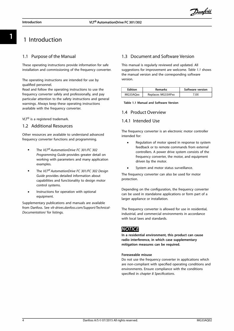
1.3 Document and Software Version
This manual is regularly reviewed and updated. Allsuggestions for improvement are welcome. Table 1.1 showsthe manual version and the corresponding softwareversion.
Edition Remarks Software version
MG33AQxx Replaces MG33APxx 7.XX
Table 1.1 Manual and Software Version
1.4 Product Overview
1.4.1 Intended Use
The frequency converter is an electronic motor controllerintended for:
• Regulation of motor speed in response to systemfeedback or to remote commands from externalcontrollers. A power drive system consists of thefrequency converter, the motor, and equipmentdriven by the motor.
• System and motor status surveillance.
The frequency converter can also be used for motorprotection.
Depending on the configuration, the frequency convertercan be used in standalone applications or form part of alarger appliance or installation.
The frequency converter is allowed for use in residential,industrial, and commercial environments in accordancewith local laws and standards.
NOTICEIn a residential environment, this product can causeradio interference, in which case supplementarymitigation measures can be required.
Foreseeable misuseDo not use the frequency converter in applications whichare non-compliant with specified operating conditions andenvironments. Ensure compliance with the conditionsspecified in chapter 8 Specifications.
Introduction VLT® AutomationDrive FC 301/302
4 Danfoss A/S © 07/2015 All rights reserved. MG33AQ02
11
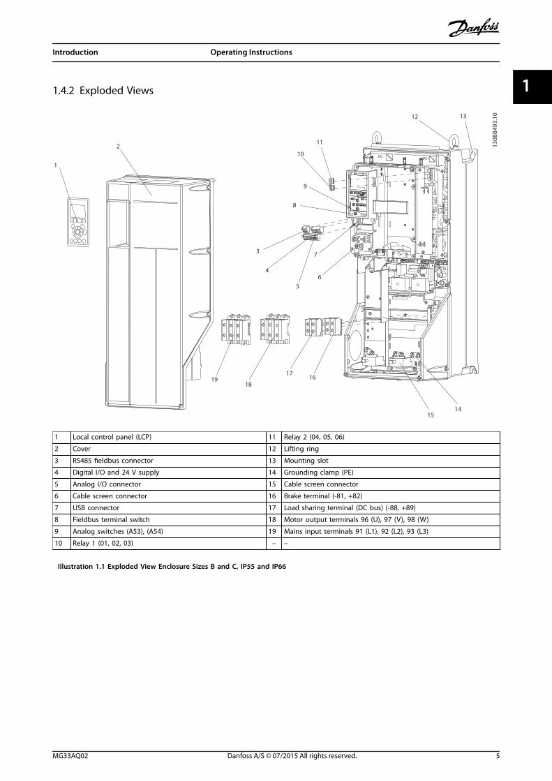
1.4.2 Exploded Views
1
2
3
4
5
6
7
8
9
10
11
12 13
1617
1819
1415
FAN MOUNTING
QDF-30
DC- DC+
Remove jumper to activate Safe StopMax. 24 Volt !
12 13 18 19 27 29 32 33 20
61 6839 42 50 53 54
0605
0403
0201
130B
B493
.10
1 Local control panel (LCP) 11 Relay 2 (04, 05, 06)
2 Cover 12 Lifting ring
3 RS485 fieldbus connector 13 Mounting slot
4 Digital I/O and 24 V supply 14 Grounding clamp (PE)
5 Analog I/O connector 15 Cable screen connector
6 Cable screen connector 16 Brake terminal (-81, +82)
7 USB connector 17 Load sharing terminal (DC bus) (-88, +89)
8 Fieldbus terminal switch 18 Motor output terminals 96 (U), 97 (V), 98 (W)
9 Analog switches (A53), (A54) 19 Mains input terminals 91 (L1), 92 (L2), 93 (L3)
10 Relay 1 (01, 02, 03) – –
Illustration 1.1 Exploded View Enclosure Sizes B and C, IP55 and IP66
Introduction Operating Instructions
MG33AQ02 Danfoss A/S © 07/2015 All rights reserved. 5
1 1
1
23
4
5
6
7
8
9
10
11
1213
14
8
15
16
17
18
130B
B492
.10
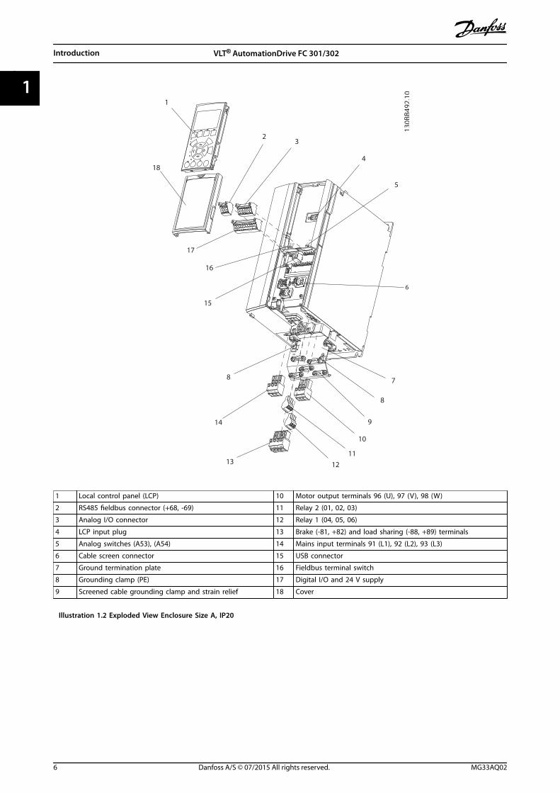
1 Local control panel (LCP) 10 Motor output terminals 96 (U), 97 (V), 98 (W)
2 RS485 fieldbus connector (+68, -69) 11 Relay 2 (01, 02, 03)
3 Analog I/O connector 12 Relay 1 (04, 05, 06)
4 LCP input plug 13 Brake (-81, +82) and load sharing (-88, +89) terminals
5 Analog switches (A53), (A54) 14 Mains input terminals 91 (L1), 92 (L2), 93 (L3)
6 Cable screen connector 15 USB connector
7 Ground termination plate 16 Fieldbus terminal switch
8 Grounding clamp (PE) 17 Digital I/O and 24 V supply
9 Screened cable grounding clamp and strain relief 18 Cover
Illustration 1.2 Exploded View Enclosure Size A, IP20
Introduction VLT® AutomationDrive FC 301/302
6 Danfoss A/S © 07/2015 All rights reserved. MG33AQ02
11
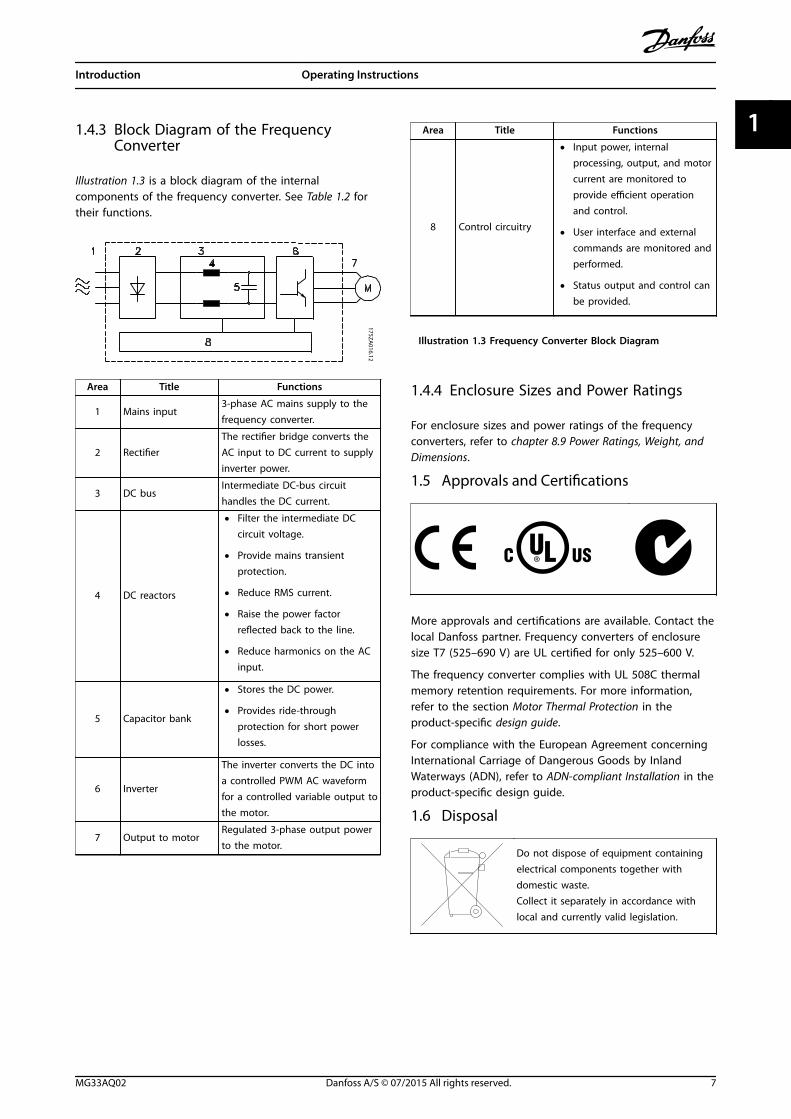
1.4.3 Block Diagram of the FrequencyConverter
Illustration 1.3 is a block diagram of the internalcomponents of the frequency converter. See Table 1.2 fortheir functions.
Area Title Functions
1 Mains input3-phase AC mains supply to thefrequency converter.
2 RectifierThe rectifier bridge converts theAC input to DC current to supplyinverter power.
3 DC busIntermediate DC-bus circuithandles the DC current.
4 DC reactors
• Filter the intermediate DCcircuit voltage.
• Provide mains transientprotection.
• Reduce RMS current.
• Raise the power factorreflected back to the line.
• Reduce harmonics on the ACinput.
5 Capacitor bank
• Stores the DC power.
• Provides ride-throughprotection for short powerlosses.
6 Inverter
The inverter converts the DC intoa controlled PWM AC waveformfor a controlled variable output tothe motor.
7 Output to motorRegulated 3-phase output powerto the motor.
Area Title Functions
8 Control circuitry
• Input power, internalprocessing, output, and motorcurrent are monitored toprovide efficient operationand control.
• User interface and externalcommands are monitored andperformed.
• Status output and control canbe provided.
Illustration 1.3 Frequency Converter Block Diagram
1.4.4 Enclosure Sizes and Power Ratings
For enclosure sizes and power ratings of the frequencyconverters, refer to chapter 8.9 Power Ratings, Weight, andDimensions.
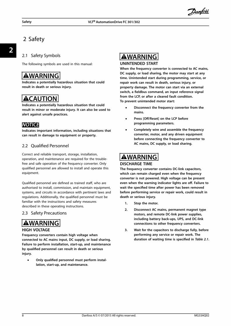
1.5 Approvals and Certifications
More approvals and certifications are available. Contact thelocal Danfoss partner. Frequency converters of enclosuresize T7 (525–690 V) are UL certified for only 525–600 V.
The frequency converter complies with UL 508C thermalmemory retention requirements. For more information,refer to the section Motor Thermal Protection in theproduct-specific design guide.
For compliance with the European Agreement concerningInternational Carriage of Dangerous Goods by InlandWaterways (ADN), refer to ADN-compliant Installation in theproduct-specific design guide.
1.6 Disposal
Do not dispose of equipment containingelectrical components together withdomestic waste.Collect it separately in accordance withlocal and currently valid legislation.
Introduction Operating Instructions
MG33AQ02 Danfoss A/S © 07/2015 All rights reserved. 7
1 1
2 Safety
2.1 Safety Symbols
The following symbols are used in this manual:
WARNINGIndicates a potentially hazardous situation that couldresult in death or serious injury.
CAUTIONIndicates a potentially hazardous situation that couldresult in minor or moderate injury. It can also be used toalert against unsafe practices.
NOTICEIndicates important information, including situations thatcan result in damage to equipment or property.
2.2 Qualified Personnel
Correct and reliable transport, storage, installation,operation, and maintenance are required for the trouble-free and safe operation of the frequency converter. Onlyqualified personnel are allowed to install and operate thisequipment.
Qualified personnel are defined as trained staff, who areauthorised to install, commission, and maintain equipment,systems, and circuits in accordance with pertinent laws andregulations. Additionally, the qualified personnel must befamiliar with the instructions and safety measuresdescribed in these operating instructions.
2.3 Safety Precautions
WARNINGHIGH VOLTAGEFrequency converters contain high voltage whenconnected to AC mains input, DC supply, or load sharing.Failure to perform installation, start-up, and maintenanceby qualified personnel can result in death or seriousinjury.
• Only qualified personnel must perform instal-lation, start-up, and maintenance.
WARNINGUNINTENDED STARTWhen the frequency converter is connected to AC mains,DC supply, or load sharing, the motor may start at anytime. Unintended start during programming, service, orrepair work can result in death, serious injury, orproperty damage. The motor can start via an externalswitch, a fieldbus command, an input reference signalfrom the LCP, or after a cleared fault condition.To prevent unintended motor start:
• Disconnect the frequency converter from themains.
• Press [Off/Reset] on the LCP beforeprogramming parameters.
• Completely wire and assemble the frequencyconverter, motor, and any driven equipmentbefore connecting the frequency converter toAC mains, DC supply, or load sharing.
WARNINGDISCHARGE TIMEThe frequency converter contains DC-link capacitors,which can remain charged even when the frequencyconverter is not powered. High voltage can be presenteven when the warning indicator lights are off. Failure towait the specified time after power has been removedbefore performing service or repair work, could result indeath or serious injury.
1. Stop the motor.
2. Disconnect AC mains, permanent magnet typemotors, and remote DC-link power supplies,including battery back-ups, UPS, and DC-linkconnections to other frequency converters.
3. Wait for the capacitors to discharge fully, beforeperforming any service or repair work. Theduration of waiting time is specified in Table 2.1.
Safety VLT® AutomationDrive FC 301/302
8 Danfoss A/S © 07/2015 All rights reserved. MG33AQ02
22
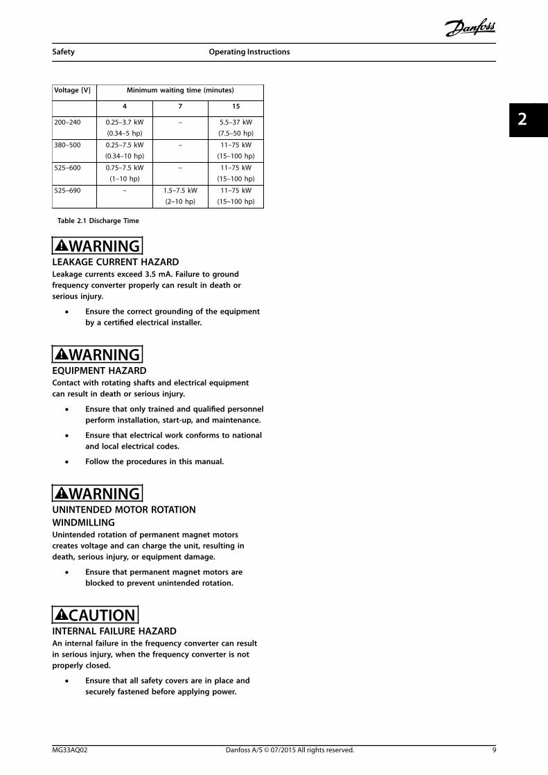
Voltage [V] Minimum waiting time (minutes)
4 7 15
200–240 0.25–3.7 kW(0.34–5 hp)
– 5.5–37 kW(7.5–50 hp)
380–500 0.25–7.5 kW(0.34–10 hp)
– 11–75 kW(15–100 hp)
525–600 0.75–7.5 kW(1–10 hp)
– 11–75 kW(15–100 hp)
525–690 – 1.5–7.5 kW(2–10 hp)
11–75 kW(15–100 hp)
Table 2.1 Discharge Time
WARNINGLEAKAGE CURRENT HAZARDLeakage currents exceed 3.5 mA. Failure to groundfrequency converter properly can result in death orserious injury.
• Ensure the correct grounding of the equipmentby a certified electrical installer.
WARNINGEQUIPMENT HAZARDContact with rotating shafts and electrical equipmentcan result in death or serious injury.
• Ensure that only trained and qualified personnelperform installation, start-up, and maintenance.
• Ensure that electrical work conforms to nationaland local electrical codes.
• Follow the procedures in this manual.
WARNINGUNINTENDED MOTOR ROTATIONWINDMILLINGUnintended rotation of permanent magnet motorscreates voltage and can charge the unit, resulting indeath, serious injury, or equipment damage.
• Ensure that permanent magnet motors areblocked to prevent unintended rotation.
CAUTIONINTERNAL FAILURE HAZARDAn internal failure in the frequency converter can resultin serious injury, when the frequency converter is notproperly closed.
• Ensure that all safety covers are in place andsecurely fastened before applying power.
Safety Operating Instructions
MG33AQ02 Danfoss A/S © 07/2015 All rights reserved. 9
2 2
3 Mechanical Installation
3.1 Unpacking
3.1.1 Items Supplied
Items supplied may vary according to product configu-ration.
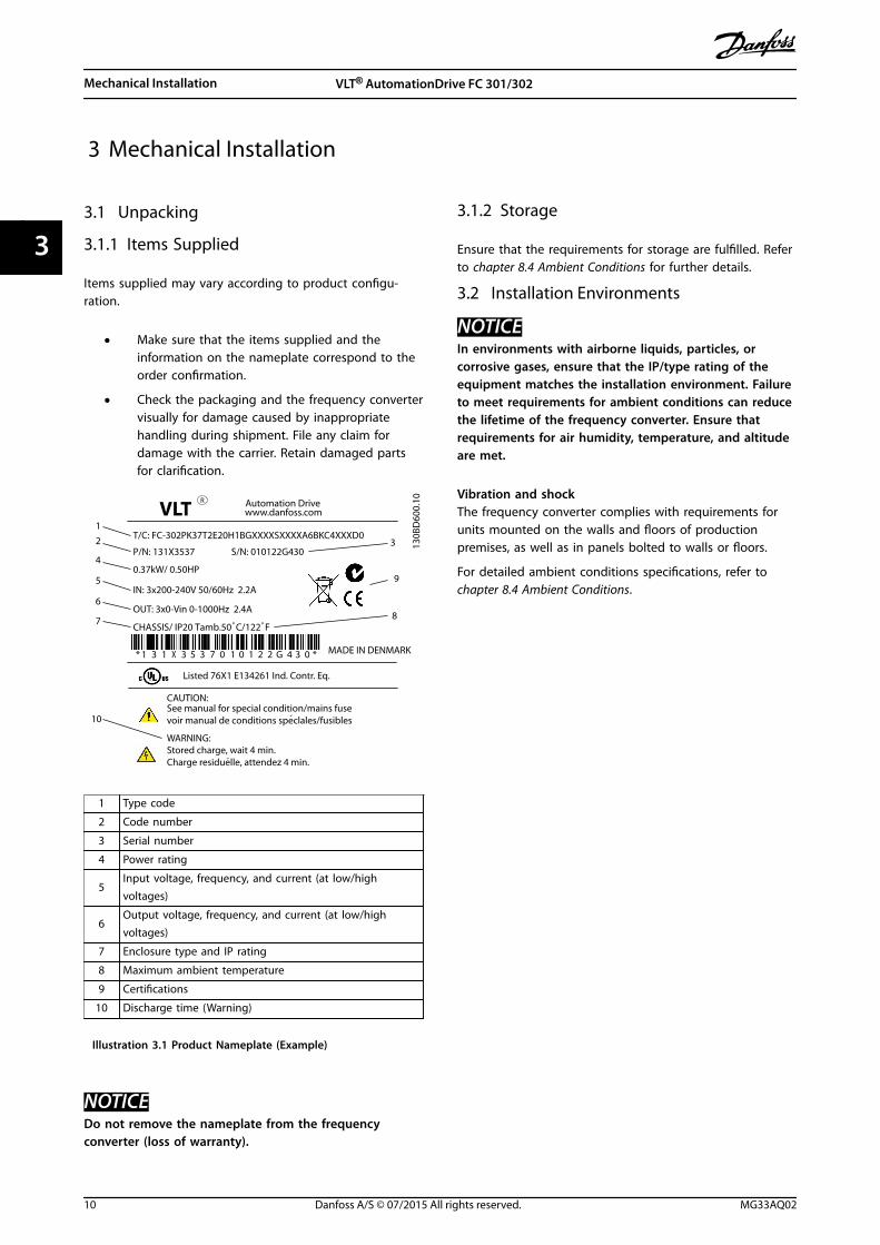
• Make sure that the items supplied and theinformation on the nameplate correspond to theorder confirmation.
• Check the packaging and the frequency convertervisually for damage caused by inappropriatehandling during shipment. File any claim fordamage with the carrier. Retain damaged partsfor clarification.
130B
D60
0.10
CHASSIS/ IP20 Tamb.50 C/122 F
VLT
MADE IN DENMARK
R
P/N: 131X3537 S/N: 010122G430
0.37kW/ 0.50HP
IN: 3x200-240V 50/60Hz 2.2A
OUT: 3x0-Vin 0-1000Hz 2.4Ao
CAUTION:See manual for special condition/mains fusevoir manual de conditions speclales/fusibles
WARNING:Stored charge, wait 4 min.Charge residuelle, attendez 4 min.
* 1 3 1 X 3 5 3 7 0 1 0 1 2 2 G 4 3 0 *
`
Automation Drivewww.danfoss.com
T/C: FC-302PK37T2E20H1BGXXXXSXXXXA6BKC4XXXD0
Listed 76X1 E134261 Ind. Contr. Eq.
o
`
12
4
5
6
7 8
9
10
3
1 Type code
2 Code number
3 Serial number
4 Power rating
5Input voltage, frequency, and current (at low/highvoltages)
6Output voltage, frequency, and current (at low/highvoltages)
7 Enclosure type and IP rating
8 Maximum ambient temperature
9 Certifications
10 Discharge time (Warning)
Illustration 3.1 Product Nameplate (Example)
NOTICEDo not remove the nameplate from the frequencyconverter (loss of warranty).
3.1.2 Storage
Ensure that the requirements for storage are fulfilled. Referto chapter 8.4 Ambient Conditions for further details.
3.2 Installation Environments
NOTICEIn environments with airborne liquids, particles, orcorrosive gases, ensure that the IP/type rating of theequipment matches the installation environment. Failureto meet requirements for ambient conditions can reducethe lifetime of the frequency converter. Ensure thatrequirements for air humidity, temperature, and altitudeare met.
Vibration and shockThe frequency converter complies with requirements forunits mounted on the walls and floors of productionpremises, as well as in panels bolted to walls or floors.
For detailed ambient conditions specifications, refer to chapter 8.4 Ambient Conditions.
Mechanical Installation VLT® AutomationDrive FC 301/302
10 Danfoss A/S © 07/2015 All rights reserved. MG33AQ02
33
3.3 Mounting
NOTICEImproper mounting can result in overheating andreduced performance.
Cooling
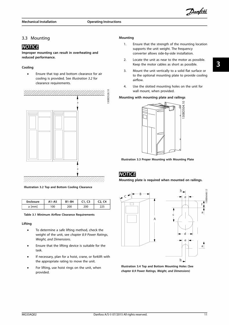
• Ensure that top and bottom clearance for aircooling is provided. See Illustration 3.2 forclearance requirements.
a
a
130B
D52
8.10
Illustration 3.2 Top and Bottom Cooling Clearance
Enclosure A1–A5 B1–B4 C1, C3 C2, C4
a [mm] 100 200 200 225
Table 3.1 Minimum Airflow Clearance Requirements
Lifting
• To determine a safe lifting method, check theweight of the unit, see chapter 8.9 Power Ratings,Weight, and Dimensions.
• Ensure that the lifting device is suitable for thetask.
• If necessary, plan for a hoist, crane, or forklift withthe appropriate rating to move the unit.
• For lifting, use hoist rings on the unit, whenprovided.
Mounting
1. Ensure that the strength of the mounting locationsupports the unit weight. The frequencyconverter allows side-by-side installation.
2. Locate the unit as near to the motor as possible.Keep the motor cables as short as possible.
3. Mount the unit vertically to a solid flat surface orto the optional mounting plate to provide coolingairflow.
4. Use the slotted mounting holes on the unit forwall mount, when provided.
Mounting with mounting plate and railings
130B
D50
4.10
Illustration 3.3 Proper Mounting with Mounting Plate
NOTICEMounting plate is required when mounted on railings.
C
a
b
130B
A64
8.12
f
e
B
A
a
d
e
b
c
Illustration 3.4 Top and Bottom Mounting Holes (See chapter 8.9 Power Ratings, Weight, and Dimensions)
Mechanical Installation Operating Instructions
MG33AQ02 Danfoss A/S © 07/2015 All rights reserved. 11
3 3
a
e
f
130B
A71
5.12
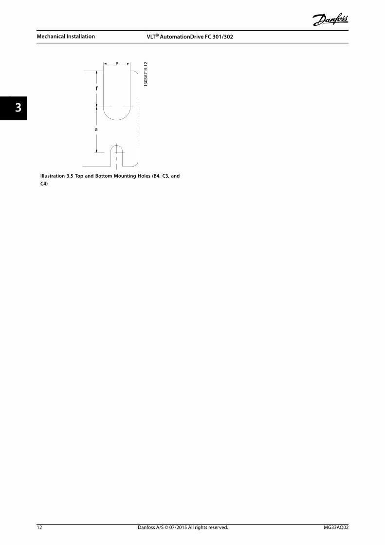
Illustration 3.5 Top and Bottom Mounting Holes (B4, C3, andC4)
Mechanical Installation VLT® AutomationDrive FC 301/302
12 Danfoss A/S © 07/2015 All rights reserved. MG33AQ02
33
4 Electrical Installation
4.1 Safety Instructions
See chapter 2 Safety for general safety instructions.
WARNINGINDUCED VOLTAGEInduced voltage from output motor cables that runtogether can charge equipment capacitors, even with theequipment turned off and locked out. Failure to runoutput motor cables separately or to use screened cablescould result in death or serious injury.
• Run output motor cables separately, or
• Use screened cables.
CAUTIONSHOCK HAZARDThe frequency converter can cause a DC current in thePE conductor. Failure to follow the recommendation maylead to the RCD not providing the intended protection.
• When a residual current-operated protectivedevice (RCD) is used for protection againstelectrical shock, only an RCD of Type B ispermitted on the supply side.
Overcurrent protection
• Extra protective equipment, such as short-circuitprotection or motor thermal protection betweenfrequency converter and motor, is required forapplications with multiple motors.
• Input fusing is required to provide short circuitand overcurrent protection. If not factory-supplied, the installer must provide fuses. Seemaximum fuse ratings in chapter 8.7 Fuses andCircuit Breakers.
Wire type and ratings
• All wiring must comply with local and nationalregulations regarding cross-section and ambienttemperature requirements.
• Power connection wire recommendation:Minimum 75 °C rated copper wire.
See chapter 8.1 Electrical Data and chapter 8.5 Cable Specifi-cations for recommended wire sizes and types.
4.2 EMC-compliant Installation
To obtain an EMC-compliant installation, follow theinstructions provided in chapter 4.3 Grounding, chapter 4.4 Wiring Schematic, chapter 4.6 Motor Connection,and chapter 4.8 Control Wiring.
4.3 Grounding
WARNINGLEAKAGE CURRENT HAZARDLeakage currents exceed 3.5 mA. Failure to ground thefrequency converter properly could result in death orserious injury.
• Ensure the correct grounding of the equipmentby a certified electrical installer.
For electrical safety
• Ground the frequency converter in accordancewith applicable standards and directives.
• Use a dedicated ground wire for input power,motor power, and control wiring.
• Do not ground one frequency converter toanother in a daisy chain fashion.
• Keep the ground wire connections as short aspossible.
• Follow motor manufacturer wiring requirements.
• Minimum cable cross-section: 10 mm2 (7 AWG)(or 2 rated ground wires terminated separately).
For EMC-compliant installation
• Establish electrical contact between the cablescreen and the frequency converter enclosure byusing metal cable glands or by using the clampsprovided on the equipment (see chapter 4.6 MotorConnection).
• Use high-strand wire to reduce electricalinterference.
• Do not use pigtails.
NOTICEPOTENTIAL EQUALISATIONRisk of electrical interference, when the ground potentialbetween the frequency converter and the control systemis different. Install equalising cables between the systemcomponents. Recommended cable cross-section: 16 mm2
(5 AWG).
Electrical Installation Operating Instructions
MG33AQ02 Danfoss A/S © 07/2015 All rights reserved. 13
4 4
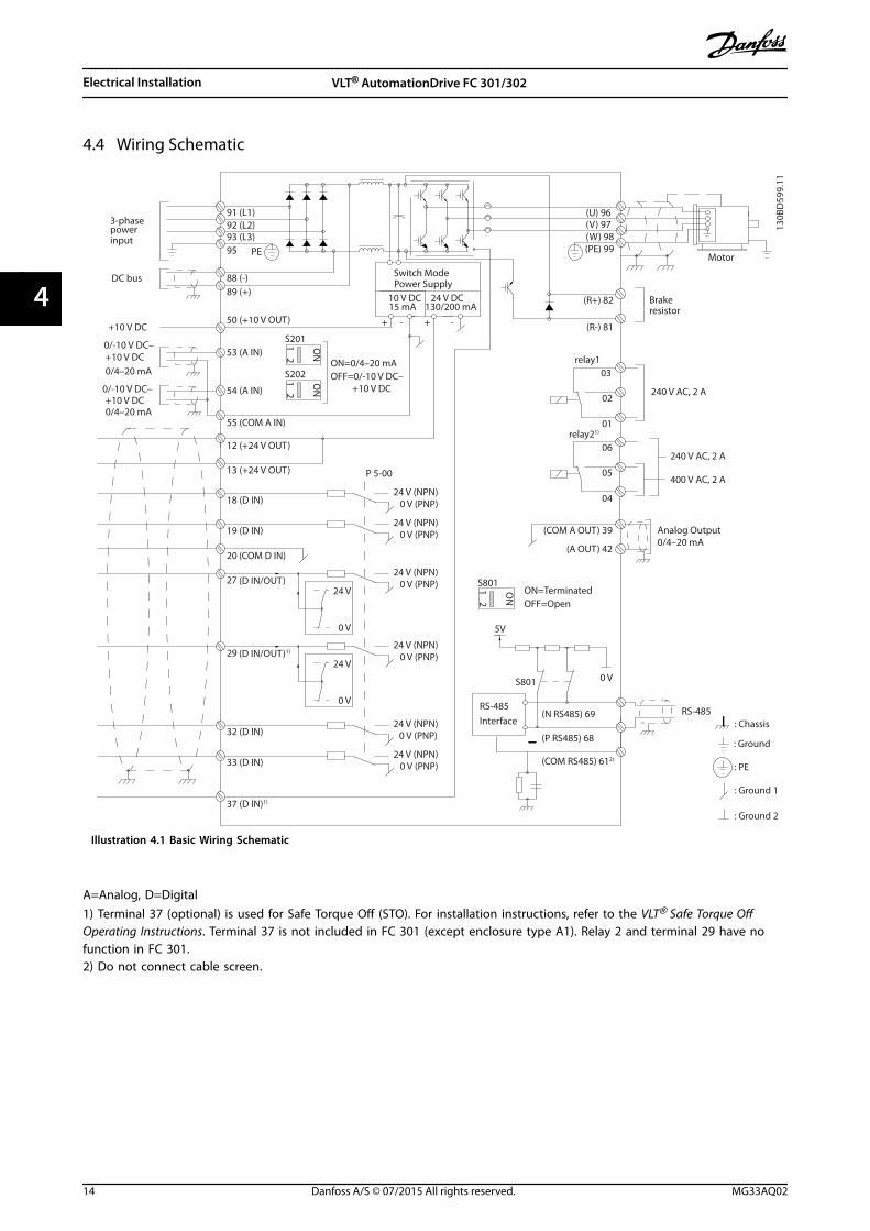
4.4 Wiring Schematic
130B
D59
9.11
3-phase
–
power
–
input
DC bus Switch ModePower Supply
Motor
Analog Output
Interface
relay1
relay21)
ON=TerminatedOFF=Open
Brakeresistor
91 (L1)92 (L2)93 (L3)
PE
88 (-)89 (+)
50 (+10 V OUT)
53 (A IN)
54 (A IN)
55 (COM A IN)0/4–20 mA
12 (+24 V OUT)
13 (+24 V OUT)
37 (D IN)1)
18 (D IN)
20 (COM D IN)
10 V DC15 mA 130/200 mA
+ - + -
(U) 96(V) 97(W) 98(PE) 99
(COM A OUT) 39
(A OUT) 42
(P RS485) 68
(N RS485) 69
(COM RS485) 612)
0 V
5V
S801
0/4–20 mA
RS-485RS-485
03
+10 V DC0/-10 V DC–
+10 V DC
+10 V DC0/4–20 mA
0/-10 V DC–
240 V AC, 2 A
24 V DC
02
01
05
04
06
24 V (NPN) 0 V (PNP)
0 V (PNP)24 V (NPN)
19 (D IN)
24 V (NPN) 0 V (PNP)27
24 V
0 V
(D IN/OUT)
0 V (PNP)24 V (NPN)
(D IN/OUT)1)
0 V
24 V29
24 V (NPN) 0 V (PNP)
0 V (PNP)24 V (NPN)
33 (D IN)
32 (D IN)
12
ON
S201
ON2
1S202ON=0/4–20 mAOFF=0/-10 V DC– +10 V DC
95
P 5-00
21 O
N
S801
(R+) 82
(R-) 81
: Chassis
240 V AC, 2 A
400 V AC, 2 A
: Ground
: Ground 1
: Ground 2
: PE
Illustration 4.1 Basic Wiring Schematic
A=Analog, D=Digital1) Terminal 37 (optional) is used for Safe Torque Off (STO). For installation instructions, refer to the VLT® Safe Torque OffOperating Instructions. Terminal 37 is not included in FC 301 (except enclosure type A1). Relay 2 and terminal 29 have nofunction in FC 301.2) Do not connect cable screen.
Electrical Installation VLT® AutomationDrive FC 301/302
14 Danfoss A/S © 07/2015 All rights reserved. MG33AQ02
44
130B
D52
9.12
1
2
3
4
5
6
7
8
9
L1L2L3PE
10 11 PE
u
v
w
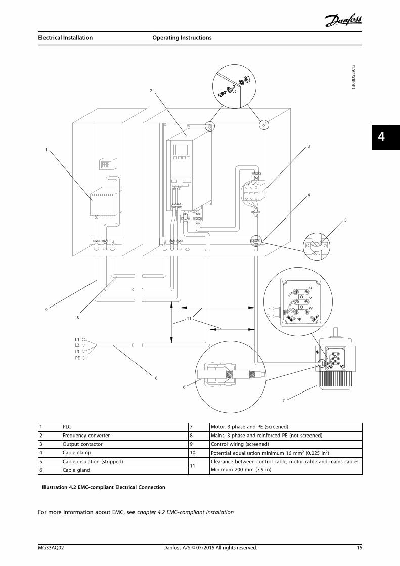
1 PLC 7 Motor, 3-phase and PE (screened)
2 Frequency converter 8 Mains, 3-phase and reinforced PE (not screened)
3 Output contactor 9 Control wiring (screened)
4 Cable clamp 10 Potential equalisation minimum 16 mm2 (0.025 in2)
5 Cable insulation (stripped)11
Clearance between control cable, motor cable and mains cable:Minimum 200 mm (7.9 in)6 Cable gland
Illustration 4.2 EMC-compliant Electrical Connection
For more information about EMC, see chapter 4.2 EMC-compliant Installation
Electrical Installation Operating Instructions
MG33AQ02 Danfoss A/S © 07/2015 All rights reserved. 15
4 4
NOTICEEMC INTERFERENCEUse screened cables for motor and control wiring, andseparate cables for input power, motor wiring, andcontrol wiring. Failure to isolate power, motor, andcontrol cables can result in unintended behaviour orreduced performance. Minimum 200 mm (7.9 in)clearance between power, motor, and control cables isrequired.
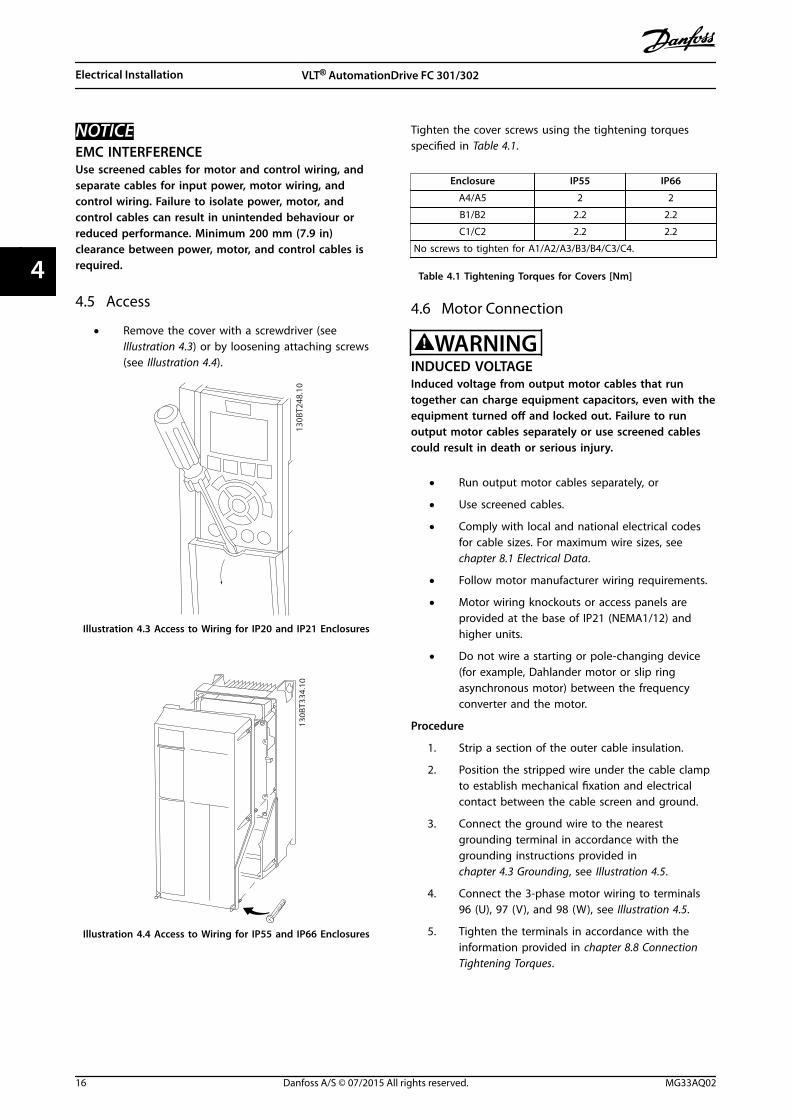
4.5 Access
• Remove the cover with a screwdriver (seeIllustration 4.3) or by loosening attaching screws(see Illustration 4.4).
130B
T248
.10
Illustration 4.3 Access to Wiring for IP20 and IP21 Enclosures
130B
T334
.10
Illustration 4.4 Access to Wiring for IP55 and IP66 Enclosures
Tighten the cover screws using the tightening torquesspecified in Table 4.1.
Enclosure IP55 IP66
A4/A5 2 2
B1/B2 2.2 2.2
C1/C2 2.2 2.2
No screws to tighten for A1/A2/A3/B3/B4/C3/C4.
Table 4.1 Tightening Torques for Covers [Nm]
4.6 Motor Connection
WARNINGINDUCED VOLTAGEInduced voltage from output motor cables that runtogether can charge equipment capacitors, even with theequipment turned off and locked out. Failure to runoutput motor cables separately or use screened cablescould result in death or serious injury.
• Run output motor cables separately, or
• Use screened cables.
• Comply with local and national electrical codesfor cable sizes. For maximum wire sizes, seechapter 8.1 Electrical Data.
• Follow motor manufacturer wiring requirements.
• Motor wiring knockouts or access panels areprovided at the base of IP21 (NEMA1/12) andhigher units.
• Do not wire a starting or pole-changing device(for example, Dahlander motor or slip ringasynchronous motor) between the frequencyconverter and the motor.
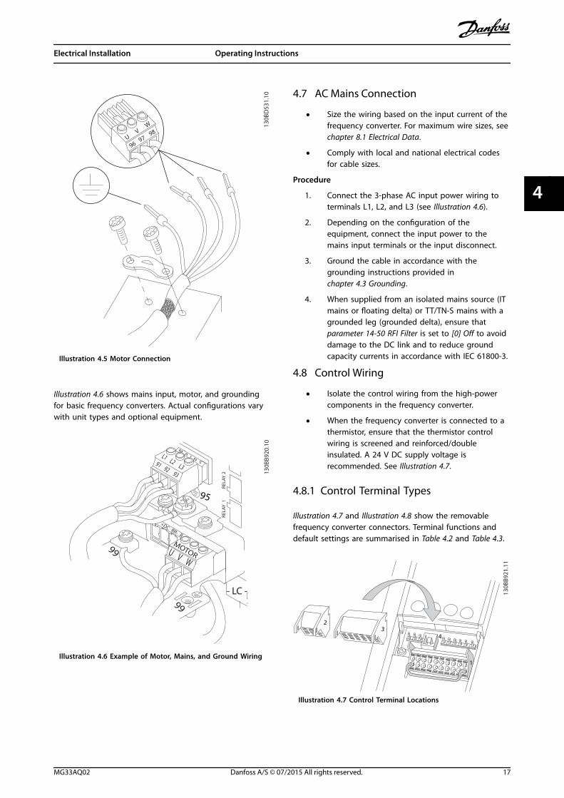
Procedure
1. Strip a section of the outer cable insulation.
2. Position the stripped wire under the cable clampto establish mechanical fixation and electricalcontact between the cable screen and ground.
3. Connect the ground wire to the nearestgrounding terminal in accordance with thegrounding instructions provided inchapter 4.3 Grounding, see Illustration 4.5.
4. Connect the 3-phase motor wiring to terminals96 (U), 97 (V), and 98 (W), see Illustration 4.5.
5. Tighten the terminals in accordance with theinformation provided in chapter 8.8 ConnectionTightening Torques.
Electrical Installation VLT® AutomationDrive FC 301/302
16 Danfoss A/S © 07/2015 All rights reserved. MG33AQ02
44
130B
D53
1.10
UV
W
9697
98
Illustration 4.5 Motor Connection
Illustration 4.6 shows mains input, motor, and groundingfor basic frequency converters. Actual configurations varywith unit types and optional equipment.
95
130B
B920
.10
+DC BR- B
MA
IN
S
L1 L2 L391 92 93
REL
AY
1
REL
AY
2
99
- LC -
U V W
MOTOR
99
Illustration 4.6 Example of Motor, Mains, and Ground Wiring
4.7 AC Mains Connection
• Size the wiring based on the input current of thefrequency converter. For maximum wire sizes, seechapter 8.1 Electrical Data.
• Comply with local and national electrical codesfor cable sizes.
Procedure
1. Connect the 3-phase AC input power wiring toterminals L1, L2, and L3 (see Illustration 4.6).
2. Depending on the configuration of theequipment, connect the input power to themains input terminals or the input disconnect.
3. Ground the cable in accordance with thegrounding instructions provided inchapter 4.3 Grounding.
4. When supplied from an isolated mains source (ITmains or floating delta) or TT/TN-S mains with agrounded leg (grounded delta), ensure thatparameter 14-50 RFI Filter is set to [0] Off to avoiddamage to the DC link and to reduce groundcapacity currents in accordance with IEC 61800-3.
4.8 Control Wiring
• Isolate the control wiring from the high-powercomponents in the frequency converter.
• When the frequency converter is connected to athermistor, ensure that the thermistor controlwiring is screened and reinforced/doubleinsulated. A 24 V DC supply voltage isrecommended. See Illustration 4.7.
4.8.1 Control Terminal Types
Illustration 4.7 and Illustration 4.8 show the removablefrequency converter connectors. Terminal functions anddefault settings are summarised in Table 4.2 and Table 4.3.
23
4
1
130B
B921
.11
Illustration 4.7 Control Terminal Locations
Electrical Installation Operating Instructions
MG33AQ02 Danfoss A/S © 07/2015 All rights reserved. 17
4 4
12 13 18 19 27 29 32 33 20 37
39 42 50 53 54 5561 68 69
130B
B931
.101
2 3
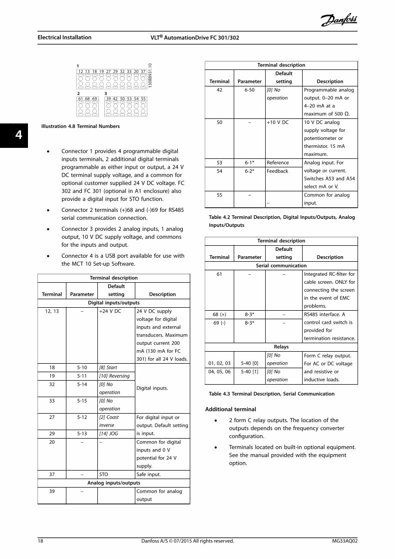
Illustration 4.8 Terminal Numbers
• Connector 1 provides 4 programmable digitalinputs terminals, 2 additional digital terminalsprogrammable as either input or output, a 24 VDC terminal supply voltage, and a common foroptional customer supplied 24 V DC voltage. FC302 and FC 301 (optional in A1 enclosure) alsoprovide a digital input for STO function.
• Connector 2 terminals (+)68 and (-)69 for RS485serial communication connection.
• Connector 3 provides 2 analog inputs, 1 analogoutput, 10 V DC supply voltage, and commonsfor the inputs and output.
• Connector 4 is a USB port available for use withthe MCT 10 Set-up Software.
Terminal description
Terminal ParameterDefaultsetting Description
Digital inputs/outputs
12, 13 – +24 V DC 24 V DC supplyvoltage for digitalinputs and externaltransducers. Maximumoutput current 200mA (130 mA for FC301) for all 24 V loads.
18 5-10 [8] Start
Digital inputs.
19 5-11 [10] Reversing
32 5-14 [0] Nooperation
33 5-15 [0] Nooperation
27 5-12 [2] Coastinverse
For digital input oroutput. Default settingis input.29 5-13 [14] JOG
20 – – Common for digitalinputs and 0 Vpotential for 24 Vsupply.
37 – STO Safe input.
Analog inputs/outputs
39 –
Common for analogoutput
Terminal description
Terminal ParameterDefaultsetting Description
42 6-50 [0] Nooperation
Programmable analogoutput. 0–20 mA or4–20 mA at a
maximum of 500 Ω.
50 – +10 V DC 10 V DC analogsupply voltage forpotentiometer orthermistor. 15 mAmaximum.
53 6-1* Reference Analog input. Forvoltage or current.Switches A53 and A54select mA or V.
54 6-2* Feedback
55 ––
Common for analoginput.
Table 4.2 Terminal Description, Digital Inputs/Outputs, AnalogInputs/Outputs
Terminal description
Terminal ParameterDefaultsetting Description
Serial communication
61 – – Integrated RC-filter forcable screen. ONLY forconnecting the screenin the event of EMCproblems.
68 (+) 8-3* – RS485 interface. Acontrol card switch isprovided fortermination resistance.
69 (-) 8-3* –
Relays
01, 02, 03 5-40 [0][0] Nooperation
Form C relay output.For AC or DC voltageand resistive orinductive loads.
04, 05, 06 5-40 [1] [0] Nooperation
Table 4.3 Terminal Description, Serial Communication
Additional terminal
• 2 form C relay outputs. The location of theoutputs depends on the frequency converterconfiguration.
• Terminals located on built-in optional equipment.See the manual provided with the equipmentoption.
Electrical Installation VLT® AutomationDrive FC 301/302
18 Danfoss A/S © 07/2015 All rights reserved. MG33AQ02
44
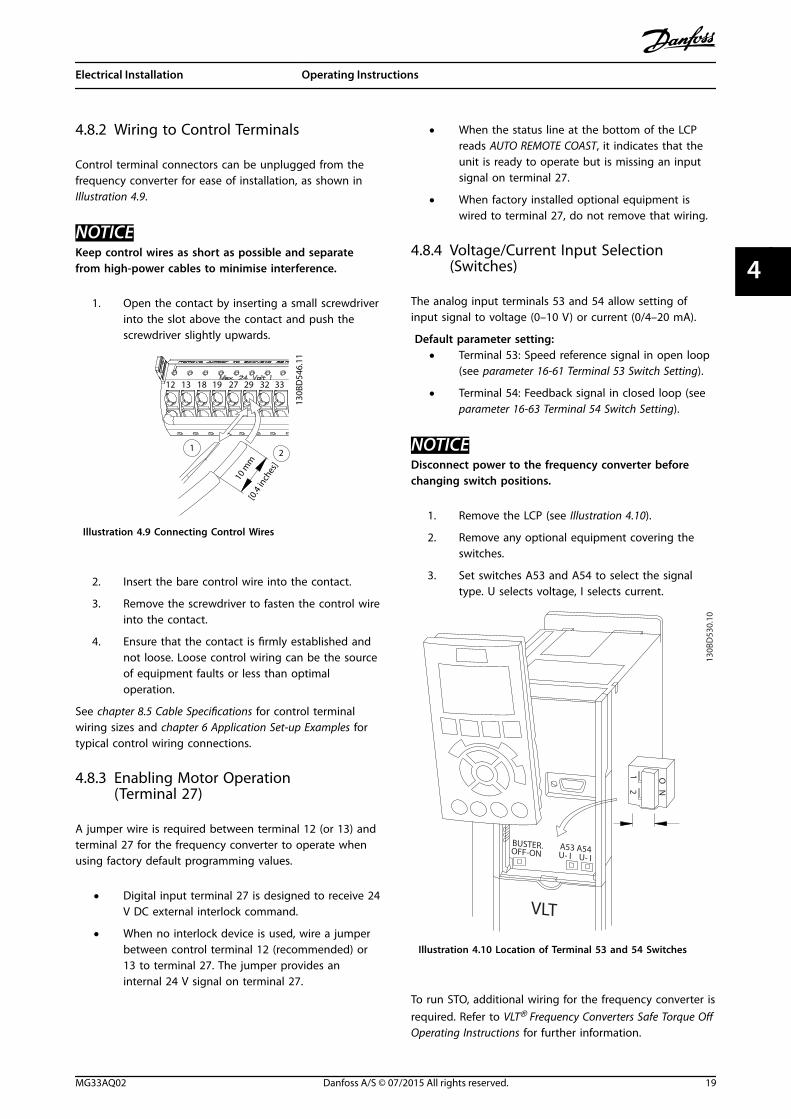
4.8.2 Wiring to Control Terminals
Control terminal connectors can be unplugged from thefrequency converter for ease of installation, as shown inIllustration 4.9.
NOTICEKeep control wires as short as possible and separatefrom high-power cables to minimise interference.
1. Open the contact by inserting a small screwdriverinto the slot above the contact and push thescrewdriver slightly upwards.
130B
D54
6.11
21
10 m
m[0
.4 in
ches
]
12 13 18 19 27 29 32 33
Illustration 4.9 Connecting Control Wires
2. Insert the bare control wire into the contact.
3. Remove the screwdriver to fasten the control wireinto the contact.
4. Ensure that the contact is firmly established andnot loose. Loose control wiring can be the sourceof equipment faults or less than optimaloperation.
See chapter 8.5 Cable Specifications for control terminalwiring sizes and chapter 6 Application Set-up Examples fortypical control wiring connections.
4.8.3 Enabling Motor Operation(Terminal 27)
A jumper wire is required between terminal 12 (or 13) andterminal 27 for the frequency converter to operate whenusing factory default programming values.
• Digital input terminal 27 is designed to receive 24V DC external interlock command.
• When no interlock device is used, wire a jumperbetween control terminal 12 (recommended) or13 to terminal 27. The jumper provides aninternal 24 V signal on terminal 27.
• When the status line at the bottom of the LCPreads AUTO REMOTE COAST, it indicates that theunit is ready to operate but is missing an inputsignal on terminal 27.
• When factory installed optional equipment iswired to terminal 27, do not remove that wiring.
4.8.4 Voltage/Current Input Selection(Switches)
The analog input terminals 53 and 54 allow setting ofinput signal to voltage (0–10 V) or current (0/4–20 mA).
Default parameter setting:• Terminal 53: Speed reference signal in open loop
(see parameter 16-61 Terminal 53 Switch Setting).
• Terminal 54: Feedback signal in closed loop (seeparameter 16-63 Terminal 54 Switch Setting).
NOTICEDisconnect power to the frequency converter beforechanging switch positions.
1. Remove the LCP (see Illustration 4.10).
2. Remove any optional equipment covering theswitches.
3. Set switches A53 and A54 to select the signaltype. U selects voltage, I selects current.
130B
D53
0.10
12
N
O
VLT
BUSTER.OFF-ON
A53 A54U- I U- I
Illustration 4.10 Location of Terminal 53 and 54 Switches
To run STO, additional wiring for the frequency converter isrequired. Refer to VLT® Frequency Converters Safe Torque OffOperating Instructions for further information.
Electrical Installation Operating Instructions
MG33AQ02 Danfoss A/S © 07/2015 All rights reserved. 19
4 4
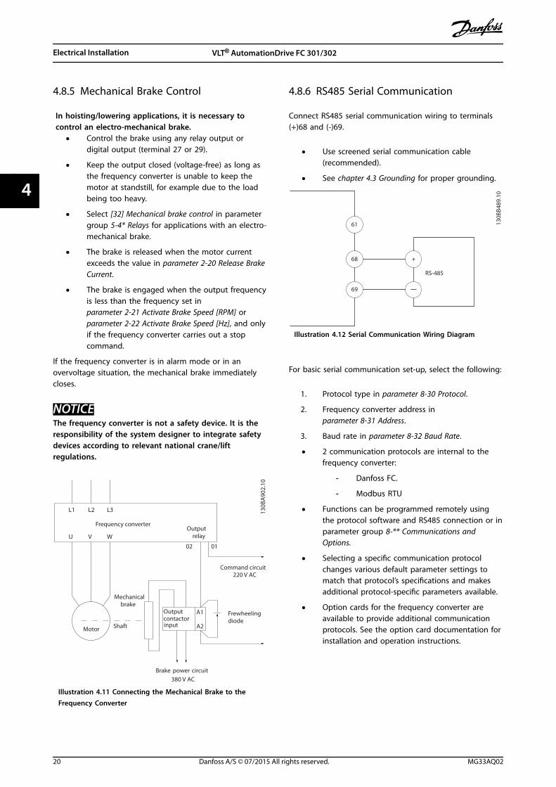
4.8.5 Mechanical Brake Control
In hoisting/lowering applications, it is necessary tocontrol an electro-mechanical brake.
• Control the brake using any relay output ordigital output (terminal 27 or 29).
• Keep the output closed (voltage-free) as long asthe frequency converter is unable to keep themotor at standstill, for example due to the loadbeing too heavy.
• Select [32] Mechanical brake control in parametergroup 5-4* Relays for applications with an electro-mechanical brake.
• The brake is released when the motor currentexceeds the value in parameter 2-20 Release BrakeCurrent.
• The brake is engaged when the output frequencyis less than the frequency set inparameter 2-21 Activate Brake Speed [RPM] orparameter 2-22 Activate Brake Speed [Hz], and onlyif the frequency converter carries out a stopcommand.
If the frequency converter is in alarm mode or in anovervoltage situation, the mechanical brake immediatelycloses.
NOTICEThe frequency converter is not a safety device. It is theresponsibility of the system designer to integrate safetydevices according to relevant national crane/liftregulations.
130B
A90
2.10
L1 L2 L3
U V W
02 01
A1
A2
Frequency converterOutput
relay
Command circuit220 V AC
Mechanicalbrake
ShaftMotor
Frewheelingdiode
Brake380 V AC
Outputcontactorinput
power circuit
Illustration 4.11 Connecting the Mechanical Brake to theFrequency Converter
4.8.6 RS485 Serial Communication
Connect RS485 serial communication wiring to terminals(+)68 and (-)69.
• Use screened serial communication cable(recommended).
• See chapter 4.3 Grounding for proper grounding.
61
68
69
+
130B
B489
.10
RS-485
Illustration 4.12 Serial Communication Wiring Diagram
For basic serial communication set-up, select the following:
1. Protocol type in parameter 8-30 Protocol.
2. Frequency converter address inparameter 8-31 Address.
3. Baud rate in parameter 8-32 Baud Rate.
• 2 communication protocols are internal to thefrequency converter:
- Danfoss FC.
- Modbus RTU
• Functions can be programmed remotely usingthe protocol software and RS485 connection or inparameter group 8-** Communications andOptions.
• Selecting a specific communication protocolchanges various default parameter settings tomatch that protocol’s specifications and makesadditional protocol-specific parameters available.
• Option cards for the frequency converter areavailable to provide additional communicationprotocols. See the option card documentation forinstallation and operation instructions.
Electrical Installation VLT® AutomationDrive FC 301/302
20 Danfoss A/S © 07/2015 All rights reserved. MG33AQ02
44
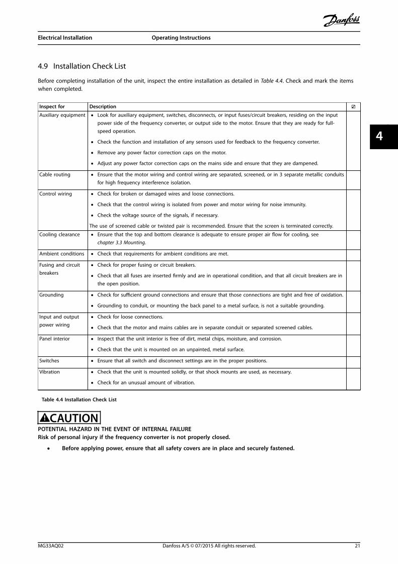
4.9 Installation Check List
Before completing installation of the unit, inspect the entire installation as detailed in Table 4.4. Check and mark the itemswhen completed.
Inspect for Description Auxiliary equipment • Look for auxiliary equipment, switches, disconnects, or input fuses/circuit breakers, residing on the input
power side of the frequency converter, or output side to the motor. Ensure that they are ready for full-speed operation.
• Check the function and installation of any sensors used for feedback to the frequency converter.
• Remove any power factor correction caps on the motor.
• Adjust any power factor correction caps on the mains side and ensure that they are dampened.
Cable routing • Ensure that the motor wiring and control wiring are separated, screened, or in 3 separate metallic conduitsfor high frequency interference isolation.
Control wiring • Check for broken or damaged wires and loose connections.
• Check that the control wiring is isolated from power and motor wiring for noise immunity.
• Check the voltage source of the signals, if necessary.
The use of screened cable or twisted pair is recommended. Ensure that the screen is terminated correctly.
Cooling clearance • Ensure that the top and bottom clearance is adequate to ensure proper air flow for cooling, see chapter 3.3 Mounting.
Ambient conditions • Check that requirements for ambient conditions are met.
Fusing and circuitbreakers
• Check for proper fusing or circuit breakers.
• Check that all fuses are inserted firmly and are in operational condition, and that all circuit breakers are inthe open position.
Grounding • Check for sufficient ground connections and ensure that those connections are tight and free of oxidation.
• Grounding to conduit, or mounting the back panel to a metal surface, is not a suitable grounding.
Input and outputpower wiring
• Check for loose connections.
• Check that the motor and mains cables are in separate conduit or separated screened cables.
Panel interior • Inspect that the unit interior is free of dirt, metal chips, moisture, and corrosion.
• Check that the unit is mounted on an unpainted, metal surface.
Switches • Ensure that all switch and disconnect settings are in the proper positions.
Vibration • Check that the unit is mounted solidly, or that shock mounts are used, as necessary.
• Check for an unusual amount of vibration.
Table 4.4 Installation Check List
CAUTIONPOTENTIAL HAZARD IN THE EVENT OF INTERNAL FAILURERisk of personal injury if the frequency converter is not properly closed.
• Before applying power, ensure that all safety covers are in place and securely fastened.
Electrical Installation Operating Instructions
MG33AQ02 Danfoss A/S © 07/2015 All rights reserved. 21
4 4
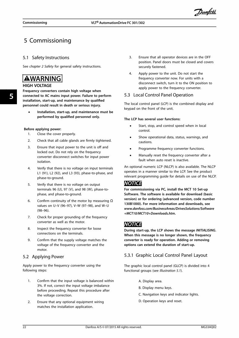
5 Commissioning
5.1 Safety Instructions
See chapter 2 Safety for general safety instructions.
WARNINGHIGH VOLTAGEFrequency converters contain high voltage whenconnected to AC mains input power. Failure to performinstallation, start-up, and maintenance by qualifiedpersonnel could result in death or serious injury.
• Installation, start-up, and maintenance must beperformed by qualified personnel only.
Before applying power:1. Close the cover properly.
2. Check that all cable glands are firmly tightened.
3. Ensure that input power to the unit is off andlocked out. Do not rely on the frequencyconverter disconnect switches for input powerisolation.
4. Verify that there is no voltage on input terminalsL1 (91), L2 (92), and L3 (93), phase-to-phase, andphase-to-ground.
5. Verify that there is no voltage on outputterminals 96 (U), 97 (V), and 98 (W), phase-to-phase, and phase-to-ground.
6. Confirm continuity of the motor by measuring Ωvalues on U–V (96–97), V–W (97–98), and W–U(98–96).
7. Check for proper grounding of the frequencyconverter as well as the motor.
8. Inspect the frequency converter for looseconnections on the terminals.
9. Confirm that the supply voltage matches thevoltage of the frequency converter and themotor.
5.2 Applying Power
Apply power to the frequency converter using thefollowing steps:
1. Confirm that the input voltage is balanced within3%. If not, correct the input voltage imbalancebefore proceeding. Repeat this procedure afterthe voltage correction.
2. Ensure that any optional equipment wiringmatches the installation application.
3. Ensure that all operator devices are in the OFFposition. Panel doors must be closed and coverssecurely fastened.
4. Apply power to the unit. Do not start thefrequency converter now. For units with adisconnect switch, turn it to the ON position toapply power to the frequency converter.
5.3 Local Control Panel Operation
The local control panel (LCP) is the combined display andkeypad on the front of the unit.
The LCP has several user functions:
• Start, stop, and control speed when in localcontrol.
• Show operational data, status, warnings, andcautions.
• Programme frequency converter functions.
• Manually reset the frequency converter after afault when auto reset is inactive.
An optional numeric LCP (NLCP) is also available. The NLCPoperates in a manner similar to the LCP. See the productrelevant programming guide for details on use of the NLCP.
NOTICEFor commissioning via PC, install the MCT 10 Set-upSoftware. The software is available for download (basicversion) or for ordering (advanced version, code number130B1000). For more information and downloads, seewww.danfoss.com/BusinessAreas/DrivesSolutions/Software+MCT10/MCT10+Downloads.htm.
NOTICEDuring start-up, the LCP shows the message INITIALISING.When this message is no longer shown, the frequencyconverter is ready for operation. Adding or removingoptions can extend the duration of start-up.
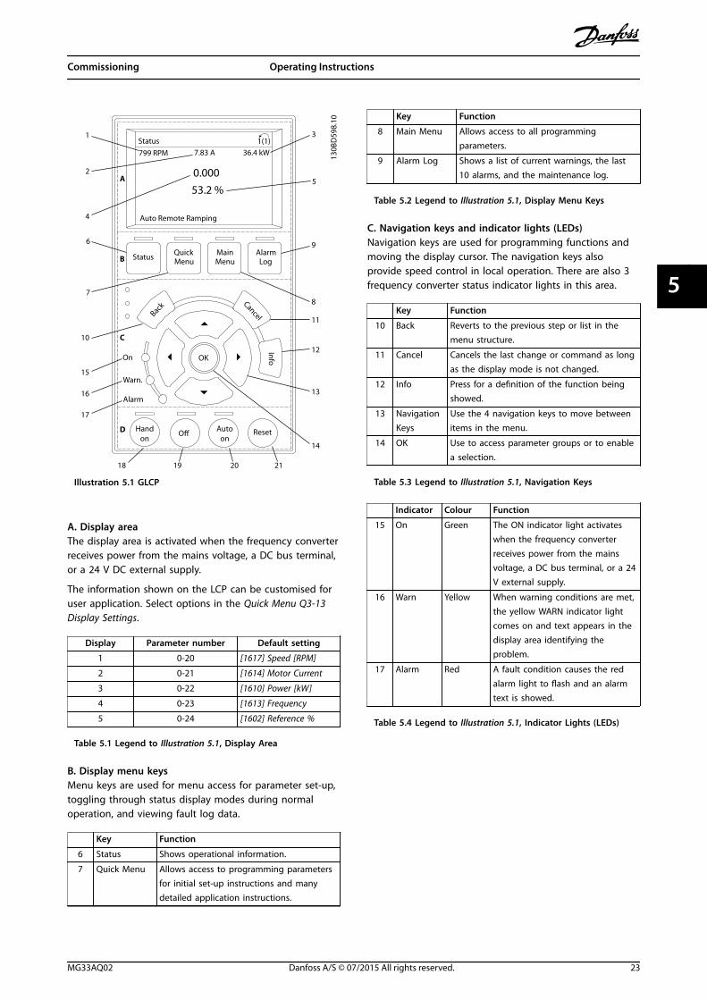
5.3.1 Graphic Local Control Panel Layout
The graphic local control panel (GLCP) is divided into 4functional groups (see Illustration 5.1).
A. Display area.
B. Display menu keys.
C. Navigation keys and indicator lights.
D. Operation keys and reset.
Commissioning VLT® AutomationDrive FC 301/302
22 Danfoss A/S © 07/2015 All rights reserved. MG33AQ02
55
130B
D59
8.10
Autoon
ResetHandon
Off
StatusQuickMenu
MainMenu
AlarmLog
Back
CancelInfoOK
Status 1(1)36.4 kW
Auto Remote Ramping
0.000
On
Alarm
Warn.
A
7.83 A799 RPM
B
C
D
53.2 %
1
2
3
4
5
6
78
9
10
11
12
13
14
15
16
17
18 19 20 21
Illustration 5.1 GLCP
A. Display areaThe display area is activated when the frequency converterreceives power from the mains voltage, a DC bus terminal,or a 24 V DC external supply.
The information shown on the LCP can be customised foruser application. Select options in the Quick Menu Q3-13Display Settings.
Display Parameter number Default setting
1 0-20 [1617] Speed [RPM]
2 0-21 [1614] Motor Current
3 0-22 [1610] Power [kW]
4 0-23 [1613] Frequency
5 0-24 [1602] Reference %
Table 5.1 Legend to Illustration 5.1, Display Area
B. Display menu keysMenu keys are used for menu access for parameter set-up,toggling through status display modes during normaloperation, and viewing fault log data.
Key Function
6 Status Shows operational information.
7 Quick Menu Allows access to programming parametersfor initial set-up instructions and manydetailed application instructions.
Key Function
8 Main Menu Allows access to all programmingparameters.
9 Alarm Log Shows a list of current warnings, the last10 alarms, and the maintenance log.
Table 5.2 Legend to Illustration 5.1, Display Menu Keys
C. Navigation keys and indicator lights (LEDs)Navigation keys are used for programming functions andmoving the display cursor. The navigation keys alsoprovide speed control in local operation. There are also 3frequency converter status indicator lights in this area.
Key Function
10 Back Reverts to the previous step or list in themenu structure.
11 Cancel Cancels the last change or command as longas the display mode is not changed.
12 Info Press for a definition of the function beingshowed.
13 NavigationKeys
Use the 4 navigation keys to move betweenitems in the menu.
14 OK Use to access parameter groups or to enablea selection.
Table 5.3 Legend to Illustration 5.1, Navigation Keys
Indicator Colour Function
15 On Green The ON indicator light activateswhen the frequency converterreceives power from the mainsvoltage, a DC bus terminal, or a 24V external supply.
16 Warn Yellow When warning conditions are met,the yellow WARN indicator lightcomes on and text appears in thedisplay area identifying theproblem.
17 Alarm Red A fault condition causes the redalarm light to flash and an alarmtext is showed.
Table 5.4 Legend to Illustration 5.1, Indicator Lights (LEDs)
Commissioning Operating Instructions
MG33AQ02 Danfoss A/S © 07/2015 All rights reserved. 23
5 5
D. Operation keys and resetOperation keys are located at the bottom of the LCP.
Key Function
18 Hand On Starts the frequency converter in localcontrol.
• An external stop signal by control inputor serial communication overrides thelocal hand on.
19 Off Stops the motor but does not remove powerto the frequency converter.
20 Auto On Puts the system in remote operational mode.
• Responds to an external start commandby control terminals or serial communi-cation.
21 Reset Resets the frequency converter manuallyafter a fault has been cleared.
Table 5.5 Legend to Illustration 5.1, Operation Keys and Reset
NOTICEThe display contrast can be adjusted by pressing [Status]and the []/[] keys.
5.3.2 Parameter Settings
Establishing the correct programming for applicationsoften requires setting functions in several relatedparameters. Details for parameters are provided in chapter 9.2 Parameter Menu Structure.
Programming data is stored internally in the frequencyconverter.
• For back-up, upload data into the LCP memory.
• To download data to another frequencyconverter, connect the LCP to that unit anddownload the stored settings.
• Restoring factory default settings does notchange data stored in the LCP memory.
5.3.3 Uploading/Downloading Data to/fromthe LCP
1. Press [Off] to stop the motor before uploading ordownloading data.
2. Press [Main Menu], select parameter 0-50 LCP Copyand press [OK].
3. Select [1] All to LCP to upload data to the LCP orselect [2] All from LCP to download data from theLCP.
4. Press [OK]. A progress bar shows the uploading ordownloading progress.
5. Press [Hand On] or [Auto On] to return to normaloperation.
5.3.4 Changing Parameter Settings
Access and change parameter settings from the QuickMenu or from the Main Menu. The Quick Menu only givesaccess to a limited number of parameters.
1. Press [Quick Menu] or [Main Menu] on the LCP.
2. Press [] [] to browse through the parametergroups, press [OK] to select a parameter group.
3. Press [] [] to browse through the parameters,press [OK] to select a parameter.
4. Press [] [] to change the value of a parametersetting.
5. Press [] [] to shift digit when a decimalparameter is in the editing state.
6. Press [OK] to accept the change.
7. Press either [Back] twice to enter Status, or press[Main Menu] once to enter the Main Menu.
View changesQuick Menu Q5 - Changes Made lists all parameterschanged from default settings.
• The list only shows parameters, which arechanged in the current edit set-up.
• Parameters, which were reset to default values,are not listed.
• The message Empty indicates that no parametersare changed.
5.3.5 Restoring Default Settings
NOTICERisk of losing programming, motor data, localisation, andmonitoring records by restoration of default settings. Toprovide a back-up, upload data to the LCP before initiali-sation.
Restoring the default parameter settings is done by initiali-sation of the frequency converter. Initialisation is carriedout through parameter 14-22 Operation Mode(recommended) or manually.
• Initialisation using parameter 14-22 OperationMode does not reset frequency converter settings,such as operating hours, serial communicationselections, personal menu settings, fault log,alarm log, and other monitoring functions.
• Manual initialisation erases all motor,programming, localisation, and monitoring dataand restores factory default settings.
Commissioning VLT® AutomationDrive FC 301/302
24 Danfoss A/S © 07/2015 All rights reserved. MG33AQ02
55
Recommended initialisation procedure, viaparameter 14-22 Operation Mode
1. Press [Main Menu] twice to access parameters.
2. Scroll to parameter 14-22 Operation Mode andpress [OK].
3. Scroll to [2] Initialisation and press [OK].
4. Remove power to the unit and wait for thedisplay to turn off.
5. Apply power to the unit.
Default parameter settings are restored during start-up.This may take slightly longer than normal.
6. Alarm 80, Drive initialised to default value isshowed.
7. Press [Reset] to return to operation mode.
Manual initialisation procedure
1. Remove power to the unit and wait for thedisplay to turn off.
2. Press and hold [Status], [Main Menu], and [OK] atthe same time while applying power to the unit(approximately 5 s or until audible click and fanstarts).
Factory default parameter settings are restored duringstart-up. This may take slightly longer than usual.
Manual initialisation does not reset the following frequencyconverter information:
• Parameter 15-00 Operating hours.
• Parameter 15-03 Power Up's.
• Parameter 15-04 Over Temp's.
• Parameter 15-05 Over Volt's.
5.4 Basic Programming
5.4.1 Commissioning with SmartStart
The SmartStart wizard enables fast configuration of basicmotor and application parameters.
• SmartStart starts automatically at first power-upor after initialisation of the frequency converter.
• Follow the on-screen instructions to complete thecommissioning of the frequency converter.Always reactivate SmartStart by selecting QuickMenu Q4 - SmartStart.
• For commissioning without use of the SmartStartwizard, refer to chapter 5.4.2 Commissioning via[Main Menu] or the programming guide.
NOTICEMotor data is required for the SmartStart set-up. Therequired data is normally available on the motornameplate.
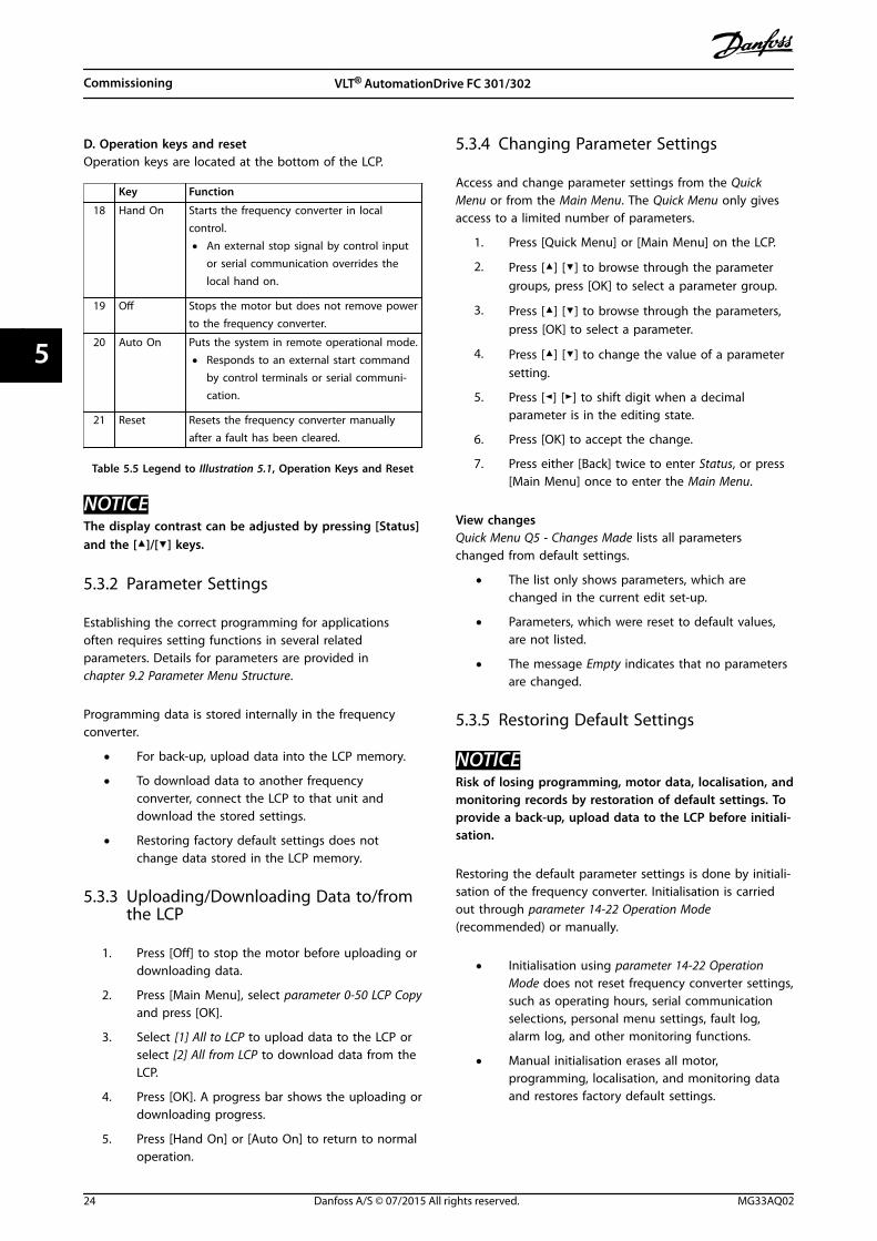
5.4.2 Commissioning via [Main Menu]
Recommended parameter settings are intended for start-up and check-out purposes. Application settings may vary.
Enter data with power ON, but before operating thefrequency converter.
1. Press [Main Menu] on the LCP.
2. Press the navigation keys to scroll to parametergroup 0-** Operation/Display and press [OK].
130B
P066
.10
1107 RPM
0 - ** Operation/Display
1 - ** Load/Motor
2 - ** Brakes
3 - ** Reference / Ramps
3.84 A 1 (1)
Main Menu
Illustration 5.2 Main Menu
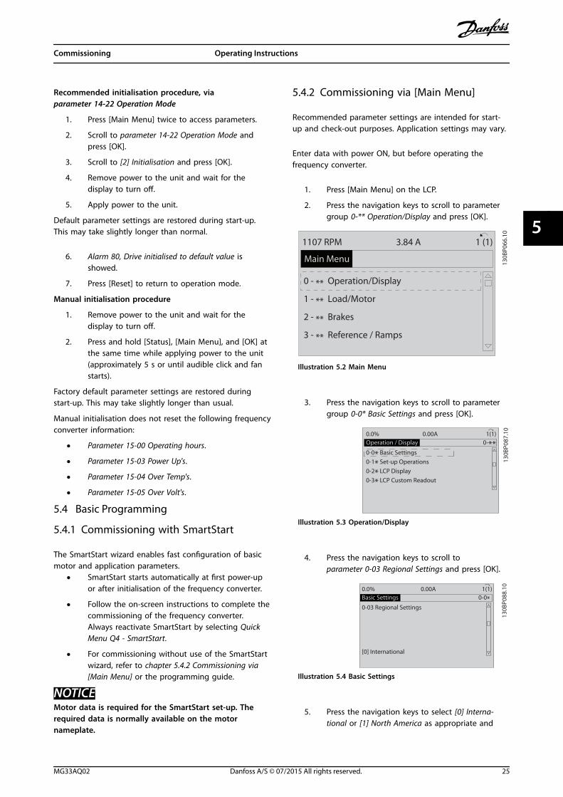
3. Press the navigation keys to scroll to parametergroup 0-0* Basic Settings and press [OK].
0-**Operation / Display0.0%
0-0* Basic Settings0-1* Set-up Operations0-2* LCP Display0-3* LCP Custom Readout
0.00A 1(1)
130B
P087
.10
Illustration 5.3 Operation/Display
4. Press the navigation keys to scroll toparameter 0-03 Regional Settings and press [OK].
0-0*Basic Settings0.0%
0-03 Regional Settings
[0] International
0.00A 1(1)
130B
P088
.10
Illustration 5.4 Basic Settings
5. Press the navigation keys to select [0] Interna-tional or [1] North America as appropriate and
Commissioning Operating Instructions
MG33AQ02 Danfoss A/S © 07/2015 All rights reserved. 25
5 5
press [OK]. (This changes the default settings fora number of basic parameters).
6. Press [Main Menu] on the LCP.
7. Press the navigation keys to scroll toparameter 0-01 Language.
8. Select the language and press [OK].
9. If a jumper wire is in place between controlterminals 12 and 27, leaveparameter 5-12 Terminal 27 Digital Input at factorydefault. Otherwise, select [0] No Operation inparameter 5-12 Terminal 27 Digital Input.
10. Make the application-specific settings in thefollowing parameters:
10a Parameter 3-02 Minimum Reference.
10b Parameter 3-03 Maximum Reference.
10c Parameter 3-41 Ramp 1 Ramp Up Time.
10d Parameter 3-42 Ramp 1 Ramp DownTime.
10e Parameter 3-13 Reference Site. Linked toHand/Auto Local Remote.
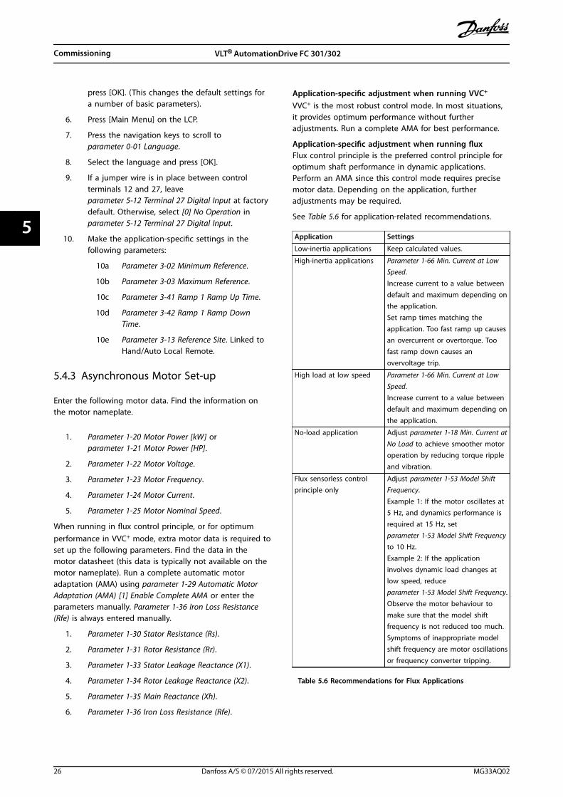
5.4.3 Asynchronous Motor Set-up
Enter the following motor data. Find the information onthe motor nameplate.
1. Parameter 1-20 Motor Power [kW] orparameter 1-21 Motor Power [HP].
2. Parameter 1-22 Motor Voltage.
3. Parameter 1-23 Motor Frequency.
4. Parameter 1-24 Motor Current.
5. Parameter 1-25 Motor Nominal Speed.
When running in flux control principle, or for optimumperformance in VVC+ mode, extra motor data is required toset up the following parameters. Find the data in themotor datasheet (this data is typically not available on themotor nameplate). Run a complete automatic motoradaptation (AMA) using parameter 1-29 Automatic MotorAdaptation (AMA) [1] Enable Complete AMA or enter theparameters manually. Parameter 1-36 Iron Loss Resistance(Rfe) is always entered manually.
1. Parameter 1-30 Stator Resistance (Rs).
2. Parameter 1-31 Rotor Resistance (Rr).
3. Parameter 1-33 Stator Leakage Reactance (X1).
4. Parameter 1-34 Rotor Leakage Reactance (X2).
5. Parameter 1-35 Main Reactance (Xh).
6. Parameter 1-36 Iron Loss Resistance (Rfe).
Application-specific adjustment when running VVC+
VVC+ is the most robust control mode. In most situations,it provides optimum performance without furtheradjustments. Run a complete AMA for best performance.
Application-specific adjustment when running fluxFlux control principle is the preferred control principle foroptimum shaft performance in dynamic applications.Perform an AMA since this control mode requires precisemotor data. Depending on the application, furtheradjustments may be required.
See Table 5.6 for application-related recommendations.
Application Settings
Low-inertia applications Keep calculated values.
High-inertia applications Parameter 1-66 Min. Current at LowSpeed.Increase current to a value betweendefault and maximum depending onthe application.Set ramp times matching theapplication. Too fast ramp up causesan overcurrent or overtorque. Toofast ramp down causes anovervoltage trip.
High load at low speed Parameter 1-66 Min. Current at LowSpeed.Increase current to a value betweendefault and maximum depending onthe application.
No-load application Adjust parameter 1-18 Min. Current atNo Load to achieve smoother motoroperation by reducing torque rippleand vibration.
Flux sensorless controlprinciple only
Adjust parameter 1-53 Model ShiftFrequency.Example 1: If the motor oscillates at5 Hz, and dynamics performance isrequired at 15 Hz, setparameter 1-53 Model Shift Frequencyto 10 Hz.Example 2: If the applicationinvolves dynamic load changes atlow speed, reduceparameter 1-53 Model Shift Frequency.Observe the motor behaviour tomake sure that the model shiftfrequency is not reduced too much.Symptoms of inappropriate modelshift frequency are motor oscillationsor frequency converter tripping.
Table 5.6 Recommendations for Flux Applications
Commissioning VLT® AutomationDrive FC 301/302
26 Danfoss A/S © 07/2015 All rights reserved. MG33AQ02
55
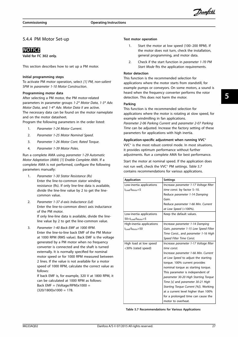
5.4.4 PM Motor Set-up
NOTICEValid for FC 302 only.
This section describes how to set up a PM motor.
Initial programming stepsTo activate PM motor operation, select [1] PM, non-salientSPM in parameter 1-10 Motor Construction.
Programming motor dataAfter selecting a PM motor, the PM motor-relatedparameters in parameter groups 1-2* Motor Data, 1-3* Adv.Motor Data, and 1-4* Adv. Motor Data II are active.The necessary data can be found on the motor nameplateand on the motor datasheet.Program the following parameters in the order listed:
1. Parameter 1-24 Motor Current.
2. Parameter 1-25 Motor Nominal Speed.
3. Parameter 1-26 Motor Cont. Rated Torque.
4. Parameter 1-39 Motor Poles.
Run a complete AMA using parameter 1-29 AutomaticMotor Adaptation (AMA) [1] Enable Complete AMA. If acomplete AMA is not performed, configure the followingparameters manually:
1. Parameter 1-30 Stator Resistance (Rs)Enter the line-to-common stator windingresistance (Rs). If only line-line data is available,divide the line-line value by 2 to get the line-common value.
2. Parameter 1-37 d-axis Inductance (Ld)Enter the line-to-common direct axis inductanceof the PM motor.If only line-line data is available, divide the line-line value by 2 to get the line-common value.
3. Parameter 1-40 Back EMF at 1000 RPM.Enter the line-to-line back EMF of the PM Motorat 1000 RPM (RMS value). Back EMF is the voltagegenerated by a PM motor when no frequencyconverter is connected and the shaft is turnedexternally. It is normally specified for nominalmotor speed or for 1000 RPM measured between2 lines. If the value is not available for a motorspeed of 1000 RPM, calculate the correct value asfollows:If back EMF is, for example, 320 V at 1800 RPM, itcan be calculated at 1000 RPM as follows:Back EMF = (Voltage/RPM)x1000 =(320/1800)x1000 = 178.
Test motor operation
1. Start the motor at low speed (100–200 RPM). Ifthe motor does not turn, check the installation,general programming, and motor data.
2. Check if the start function in parameter 1-70 PMStart Mode fits the application requirements.
Rotor detectionThis function is the recommended selection forapplications where the motor starts from standstill, forexample pumps or conveyors. On some motors, a sound isheard when the frequency converter performs the rotordetection. This does not harm the motor.
ParkingThis function is the recommended selection forapplications where the motor is rotating at slow speed, forexample windmilling in fan applications.Parameter 2-06 Parking Current and parameter 2-07 ParkingTime can be adjusted. Increase the factory setting of theseparameters for applications with high inertia.
Application-specific adjustment when running VVC+
VVC+ is the most robust control mode. In most situations,it provides optimum performance without furtheradjustments. Run a complete AMA for best performance.
Start the motor at nominal speed. If the application doesnot run well, check the VVC+ PM settings. Table 5.7contains recommendations for various applications.
Application Settings
Low-inertia applicationsILoad/IMotor<5
Increase parameter 1-17 Voltage filtertime const. by factor 5–10.Reduce parameter 1-14 DampingGain.Reduce parameter 1-66 Min. Currentat Low Speed (<100%).
Low-inertia applications50>ILoad/IMotor>5
Keep the default values.
High-inertia applicationsILoad/IMotor>50
Increase parameter 1-14 DampingGain, parameter 1-15 Low Speed FilterTime Const., and parameter 1-16 HighSpeed Filter Time Const.
High load at low speed<30% (rated speed)
Increase parameter 1-17 Voltage filtertime const.Increase parameter 1-66 Min. Currentat Low Speed to adjust the startingtorque. 100% current providesnominal torque as starting torque.This parameter is independent ofparameter 30-20 High Starting TorqueTime [s] and parameter 30-21 HighStarting Torque Current [%]). Workingat a current level higher than 100%for a prolonged time can cause themotor to overheat.
Table 5.7 Recommendations for Various Applications
Commissioning Operating Instructions
MG33AQ02 Danfoss A/S © 07/2015 All rights reserved. 27
5 5
If the motor starts oscillating at a certain speed, increaseparameter 1-14 Damping Gain. Increase the value in smallsteps. Depending on the motor, this parameter can be setto 10–100% higher than the default value.
Application-specific adjustment when running fluxFlux control principle is the preferred control principle foroptimum shaft performance in dynamic applications.Perform an AMA because this control mode requiresprecise motor data. Depending on the application, furtheradjustments may be required.See chapter 5.4.3 Asynchronous Motor Set-up for application-specific recommendations.
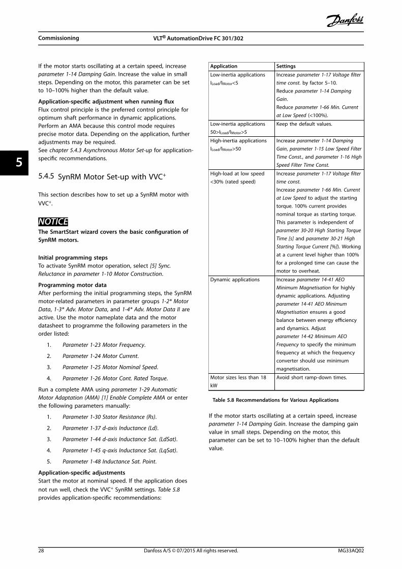
5.4.5 SynRM Motor Set-up with VVC+
This section describes how to set up a SynRM motor withVVC+.
NOTICEThe SmartStart wizard covers the basic configuration ofSynRM motors.
Initial programming stepsTo activate SynRM motor operation, select [5] Sync.Reluctance in parameter 1-10 Motor Construction.
Programming motor dataAfter performing the initial programming steps, the SynRMmotor-related parameters in parameter groups 1-2* MotorData, 1-3* Adv. Motor Data, and 1-4* Adv. Motor Data II areactive. Use the motor nameplate data and the motordatasheet to programme the following parameters in theorder listed:
1. Parameter 1-23 Motor Frequency.
2. Parameter 1-24 Motor Current.
3. Parameter 1-25 Motor Nominal Speed.
4. Parameter 1-26 Motor Cont. Rated Torque.
Run a complete AMA using parameter 1-29 AutomaticMotor Adaptation (AMA) [1] Enable Complete AMA or enterthe following parameters manually:
1. Parameter 1-30 Stator Resistance (Rs).
2. Parameter 1-37 d-axis Inductance (Ld).
3. Parameter 1-44 d-axis Inductance Sat. (LdSat).
4. Parameter 1-45 q-axis Inductance Sat. (LqSat).
5. Parameter 1-48 Inductance Sat. Point.
Application-specific adjustmentsStart the motor at nominal speed. If the application doesnot run well, check the VVC+ SynRM settings. Table 5.8provides application-specific recommendations:
Application Settings
Low-inertia applicationsILoad/IMotor<5
Increase parameter 1-17 Voltage filtertime const. by factor 5–10.Reduce parameter 1-14 DampingGain.Reduce parameter 1-66 Min. Currentat Low Speed (<100%).
Low-inertia applications50>ILoad/IMotor>5
Keep the default values.
High-inertia applicationsILoad/IMotor>50
Increase parameter 1-14 DampingGain, parameter 1-15 Low Speed FilterTime Const., and parameter 1-16 HighSpeed Filter Time Const.
High-load at low speed<30% (rated speed)
Increase parameter 1-17 Voltage filtertime const.Increase parameter 1-66 Min. Currentat Low Speed to adjust the startingtorque. 100% current providesnominal torque as starting torque.This parameter is independent ofparameter 30-20 High Starting TorqueTime [s] and parameter 30-21 HighStarting Torque Current [%]). Workingat a current level higher than 100%for a prolonged time can cause themotor to overheat.
Dynamic applications Increase parameter 14-41 AEOMinimum Magnetisation for highlydynamic applications. Adjustingparameter 14-41 AEO MinimumMagnetisation ensures a goodbalance between energy efficiencyand dynamics. Adjustparameter 14-42 Minimum AEOFrequency to specify the minimumfrequency at which the frequencyconverter should use minimummagnetisation.
Motor sizes less than 18kW
Avoid short ramp-down times.
Table 5.8 Recommendations for Various Applications
If the motor starts oscillating at a certain speed, increaseparameter 1-14 Damping Gain. Increase the damping gainvalue in small steps. Depending on the motor, thisparameter can be set to 10–100% higher than the defaultvalue.
Commissioning VLT® AutomationDrive FC 301/302
28 Danfoss A/S © 07/2015 All rights reserved. MG33AQ02
55
5.4.6 Automatic Motor Adaptation (AMA)
AMA is a procedure which optimises compatibility betweenthe frequency converter and the motor.
• The frequency converter builds a mathematicalmodel of the motor for regulating output motorcurrent. The procedure also tests the input phasebalance of electrical power. It compares themotor characteristics with the entered nameplatedata.
• The motor shaft does not turn and no harm isdone to the motor while running the AMA.
• Some motors may be unable to run the completeversion of the test. In that case, select [2] Enablereduced AMA.
• If an output filter is connected to the motor,select [2] Enable reduced AMA.
• If warnings or alarms occur, see chapter 7.4 List ofWarnings and Alarms.
• Run this procedure on a cold motor for bestresults.
To run AMA1. Press [Main Menu] to access parameters.
2. Scroll to parameter group 1-** Load and Motorand press [OK].
3. Scroll to parameter group 1-2* Motor Data andpress [OK].
4. Scroll to parameter 1-29 Automatic MotorAdaptation (AMA) and press [OK].
5. Select [1] Enable complete AMA and press [OK].
6. Follow the on-screen instructions.
7. The test runs automatically and indicates when itis complete.
8. The advanced motor data is entered in parametergroup 1-3* Adv. Motor Data.
5.5 Checking Motor Rotation
Before running the frequency converter, check the motorrotation.
1. Press [Hand On].
2. Press [] for positive speed reference.
3. Check that the speed displayed is positive.
When parameter 1-06 Clockwise Direction is set to [0]Normal (default clockwise):
4a. Verify that the motor turns clockwise.
5a. Verify that the LCP direction arrow isclockwise.
When parameter 1-06 Clockwise Direction is set to [1] Inverse(counterclockwise):
4b. Verify that the motor turns counter-clockwise.
5b. Verify that the LCP direction arrow is counter-clockwise.
5.6 Checking Encoder Rotation
Only check encoder rotation if encoder feedback is used.For more information on the encoder option, refer to theoption manual.
1. Select [0] Open Loop in parameter 1-00 Configu-ration Mode.
2. Select [1] 24 V encoder in parameter 7-00 SpeedPID Feedback Source.
3. Press [Hand On].
4. Press [] for positive speed reference(parameter 1-06 Clockwise Direction at [0] Normal).
5. In parameter 16-57 Feedback [RPM], check that thefeedback is positive.
NOTICENEGATIVE FEEDBACKIf the feedback is negative, the encoder connection iswrong. Use either parameter 5-71 Term 32/33 EncoderDirection or parameter 17-60 Feedback Direction toinverse the direction, or reverse the encoder cables.Parameter 17-60 Feedback Direction is only available withthe VLT® Encoder Input MCB 102 option.
5.7 Local-control Test
1. Press [Hand On] to provide a local start commandto the frequency converter.
2. Accelerate the frequency converter by pressing[] to full speed. Moving the cursor left of thedecimal point provides quicker input changes.
3. Note any acceleration problems.
4. Press [Off]. Note any deceleration problems.
In the event of acceleration or deceleration problems, see chapter 7.5 Troubleshooting. See chapter 7.4 List of Warningsand Alarms for resetting the frequency converter after atrip.
Commissioning Operating Instructions
MG33AQ02 Danfoss A/S © 07/2015 All rights reserved. 29
5 5
5.8 System Start-up
The procedure in this section requires wiring andapplication programming to be completed. The followingprocedure is recommended after application set-up iscompleted.
1. Press [Auto On].
2. Apply an external run command.
3. Adjust the speed reference throughout the speedrange.
4. Remove the external run command.
5. Check the sound and vibration levels of themotor to ensure that the system is working asintended.
If warnings or alarms occur, see or chapter 7.4 List ofWarnings and Alarms.
Commissioning VLT® AutomationDrive FC 301/302
30 Danfoss A/S © 07/2015 All rights reserved. MG33AQ02
55
6 Application Set-up Examples
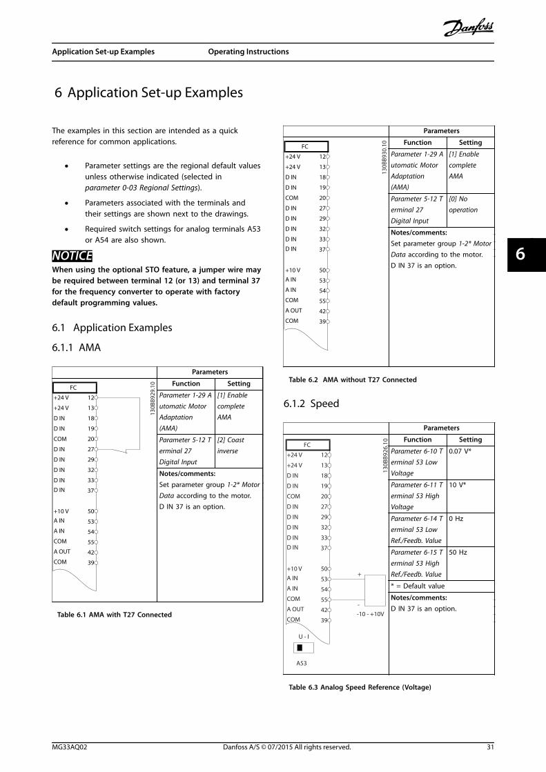
The examples in this section are intended as a quickreference for common applications.
• Parameter settings are the regional default valuesunless otherwise indicated (selected inparameter 0-03 Regional Settings).
• Parameters associated with the terminals andtheir settings are shown next to the drawings.
• Required switch settings for analog terminals A53or A54 are also shown.
NOTICEWhen using the optional STO feature, a jumper wire maybe required between terminal 12 (or 13) and terminal 37for the frequency converter to operate with factorydefault programming values.
6.1 Application Examples
6.1.1 AMA
Parameters
FC
+24 V
+24 V
D IN
D IN
D IN
COM
D IN
D IN
D IN
D IN
+10 V
A IN
A IN
COM
A OUT
COM
12
13
18
19
20
27
29
32
33
37
50
53
54
55
42
39
130B
B929
.10 Function Setting
Parameter 1-29 Automatic MotorAdaptation(AMA)
[1] EnablecompleteAMA
Parameter 5-12 Terminal 27Digital Input
[2] Coastinverse
Notes/comments:Set parameter group 1-2* MotorData according to the motor.D IN 37 is an option.
Table 6.1 AMA with T27 Connected
Parameters
FC
+24 V
+24 V
D IN
D IN
D IN
COM
D IN
D IN
D IN
D IN
+10 V
A IN
A IN
COM
A OUT
COM
12
13
18
19
20
27
29
32
33
37
50
53
54
55
42
39
130B
B930
.10 Function Setting
Parameter 1-29 Automatic MotorAdaptation(AMA)
[1] EnablecompleteAMA
Parameter 5-12 Terminal 27Digital Input
[0] Nooperation
Notes/comments:Set parameter group 1-2* MotorData according to the motor.D IN 37 is an option.
Table 6.2 AMA without T27 Connected
6.1.2 Speed
Parameters
FC
+24 V
+24 V
D IN
D IN
D IN
COM
D IN
D IN
D IN
D IN
+10 V
A IN
A IN
COM
A OUT
COM
12
13
18
19
20
27
29
32
33
37
50
53
54
55
42
39
A53
U - I
-10 - +10V
+
-
130B
B926
.10 Function Setting
Parameter 6-10 Terminal 53 LowVoltage
0.07 V*
Parameter 6-11 Terminal 53 HighVoltage
10 V*
Parameter 6-14 Terminal 53 LowRef./Feedb. Value
0 Hz
Parameter 6-15 Terminal 53 HighRef./Feedb. Value
50 Hz
* = Default value
Notes/comments:D IN 37 is an option.
Table 6.3 Analog Speed Reference (Voltage)
Application Set-up Examples Operating Instructions
MG33AQ02 Danfoss A/S © 07/2015 All rights reserved. 31
6 6
Parameters
130B
B927
.10
FC
+24 V
+24 V
D IN
D IN
D IN
COM
D IN
D IN
D IN
D IN
+10 VA IN
A IN
COM
A OUT
COM
12
13
18
19
20
27
29
32
33
37
50
53
54
55
42
39
A53
U - I
4 - 20mA
+
-
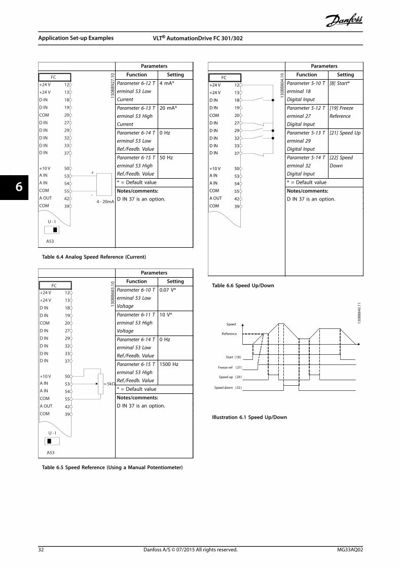
Function Setting
Parameter 6-12 Terminal 53 LowCurrent
4 mA*
Parameter 6-13 Terminal 53 HighCurrent
20 mA*
Parameter 6-14 Terminal 53 LowRef./Feedb. Value
0 Hz
Parameter 6-15 Terminal 53 HighRef./Feedb. Value
50 Hz
* = Default value
Notes/comments:D IN 37 is an option.
Table 6.4 Analog Speed Reference (Current)
Parameters
FC
+24 V
+24 V
D IN
D IN
D IN
COM
D IN
D IN
D IN
D IN
+10 V
A IN
A IN
COM
A OUT
COM
12
13
18
19
20
27
29
32
33
37
50
53
54
55
42
39
A53
U - I
≈ 5kΩ
130B
B683
.10 Function Setting
Parameter 6-10 Terminal 53 LowVoltage
0.07 V*
Parameter 6-11 Terminal 53 HighVoltage
10 V*
Parameter 6-14 Terminal 53 LowRef./Feedb. Value
0 Hz
Parameter 6-15 Terminal 53 HighRef./Feedb. Value
1500 Hz
* = Default value
Notes/comments:D IN 37 is an option.
Table 6.5 Speed Reference (Using a Manual Potentiometer)
Parameters
FC
+24 V
+24 V
D IN
D IN
D IN
COM
D IN
D IN
D IN
D IN
+10 V
A IN
A IN
COM
A OUT
COM
12
13
18
19
20
27
29
32
33
37
50
53
54
55
42
39
130B
B804
.10 Function Setting
Parameter 5-10 Terminal 18Digital Input
[8] Start*
Parameter 5-12 Terminal 27Digital Input
[19] FreezeReference
Parameter 5-13 Terminal 29Digital Input
[21] Speed Up
Parameter 5-14 Terminal 32Digital Input
[22] SpeedDown
* = Default value
Notes/comments:D IN 37 is an option.
Table 6.6 Speed Up/Down
Start (18)
Freeze ref (27)
Speed up (29 )
Speed down (32 )
Speed
Reference
130B
B840
.11
Illustration 6.1 Speed Up/Down
Application Set-up Examples VLT® AutomationDrive FC 301/302
32 Danfoss A/S © 07/2015 All rights reserved. MG33AQ02
66
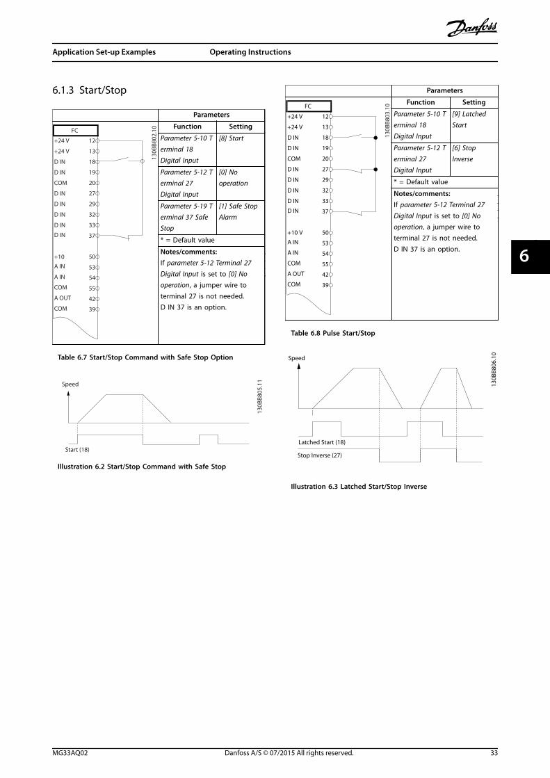
6.1.3 Start/Stop
Parameters
FC
+24 V
+24 V
D IN
D IN
D IN
COM
D IN
D IN
D IN
D IN
+10
A IN
A IN
COM
A OUT
COM
12
13
18
19
20
27
29
32
33
37
50
53
54
55
42
39
130B
B802
.10 Function Setting
Parameter 5-10 Terminal 18Digital Input
[8] Start
Parameter 5-12 Terminal 27Digital Input
[0] Nooperation
Parameter 5-19 Terminal 37 SafeStop
[1] Safe StopAlarm
* = Default value
Notes/comments:If parameter 5-12 Terminal 27Digital Input is set to [0] Nooperation, a jumper wire toterminal 27 is not needed.D IN 37 is an option.
Table 6.7 Start/Stop Command with Safe Stop Option
130B
B805
.11
Speed
Start (18)
Illustration 6.2 Start/Stop Command with Safe Stop
Parameters
FC
+24 V
+24 V
D IN
D IN
D IN
COM
D IN
D IN
D IN
D IN
+10 V
A IN
A IN
COM
A OUT
COM
12
13
18
19
20
27
29
32
33
37
50
53
54
55
42
39
130B
B803
.10 Function Setting
Parameter 5-10 Terminal 18Digital Input
[9] LatchedStart
Parameter 5-12 Terminal 27Digital Input
[6] StopInverse
* = Default value
Notes/comments:If parameter 5-12 Terminal 27Digital Input is set to [0] Nooperation, a jumper wire toterminal 27 is not needed.D IN 37 is an option.
Table 6.8 Pulse Start/Stop
Speed
130B
B806
.10
Latched Start (18)
Stop Inverse (27)
Illustration 6.3 Latched Start/Stop Inverse
Application Set-up Examples Operating Instructions
MG33AQ02 Danfoss A/S © 07/2015 All rights reserved. 33
6 6
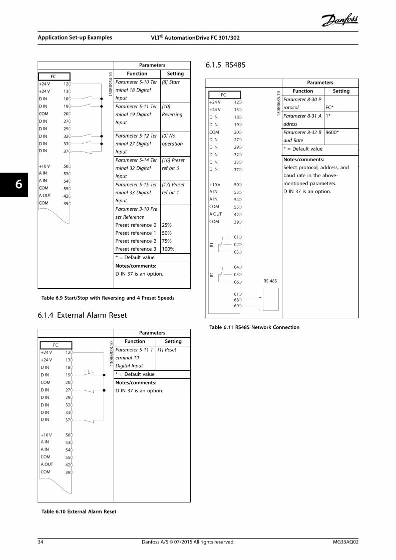
Parameters
FC
+24 V
+24 V
D IN
D IN
D IN
COM
D IN
D IN
D IN
D IN
+10 V
A IN
A IN
COM
A OUT
COM
12
13
18
19
20
27
29
32
33
37
50
53
54
55
42
39
130B
B934
.10 Function Setting
Parameter 5-10 Terminal 18 DigitalInput
[8] Start
Parameter 5-11 Terminal 19 DigitalInput
[10]Reversing
Parameter 5-12 Terminal 27 DigitalInput
[0] Nooperation
Parameter 5-14 Terminal 32 DigitalInput
[16] Presetref bit 0
Parameter 5-15 Terminal 33 DigitalInput
[17] Presetref bit 1
Parameter 3-10 Preset Reference
Preset reference 0Preset reference 1Preset reference 2Preset reference 3
25%50%75%100%
* = Default value
Notes/comments:D IN 37 is an option.
Table 6.9 Start/Stop with Reversing and 4 Preset Speeds
6.1.4 External Alarm Reset
Parameters
FC
+24 V
+24 V
D IN
D IN
D IN
COM
D IN
D IN
D IN
D IN
+10 V
A IN
A IN
COM
A OUT
COM
12
13
18
19
20
27
29
32
33
37
50
53
54
55
42
39
130B
B928
.10 Function Setting
Parameter 5-11 Terminal 19Digital Input
[1] Reset
* = Default value
Notes/comments:D IN 37 is an option.
Table 6.10 External Alarm Reset
6.1.5 RS485
Parameters
FC
+24 V
+24 V
D IN
D IN
D IN
COM
D IN
D IN
D IN
D IN
+10 V
A IN
A IN
COM
A OUT
COM
R1R2
12
13
18
19
20
27
29
32
33
37
50
53
54
55
42
39
01
02
03
04
05
06
-
616869
RS-485
+
130B
B685
.10 Function Setting
Parameter 8-30 Protocol FC*
Parameter 8-31 Address
1*
Parameter 8-32 Baud Rate
9600*
* = Default value
Notes/comments:Select protocol, address, andbaud rate in the above-mentioned parameters.D IN 37 is an option.
Table 6.11 RS485 Network Connection
Application Set-up Examples VLT® AutomationDrive FC 301/302
34 Danfoss A/S © 07/2015 All rights reserved. MG33AQ02
66
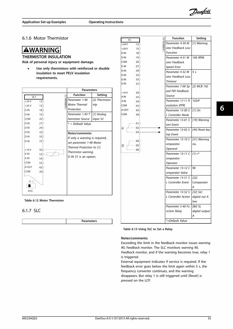
6.1.6 Motor Thermistor
WARNINGTHERMISTOR INSULATIONRisk of personal injury or equipment damage.
• Use only thermistors with reinforced or doubleinsulation to meet PELV insulationrequirements.
Parameters
130B
B686
.12
VLT
+24 V
+24 V
D IN
D IN
D IN
COM
D IN
D IN
D IN
+10 VA IN
A IN
COM
A OUT
COM
12
13
18
19
20
27
29
32
33
50
53
54
55
42
39
A53
U - I
D IN 37
Function Setting
Parameter 1-90 Motor ThermalProtection
[2] Thermistortrip
Parameter 1-93 Thermistor Source
[1] Analoginput 53
* = Default Value
Notes/comments:If only a warning is required,set parameter 1-90 MotorThermal Protection to [1]Thermistor warning.D IN 37 is an option.
Table 6.12 Motor Thermistor
6.1.7 SLC
Parameters
FC
+24 V
+24 V
D IN
D IN
D IN
COM
D IN
D IN
D IN
D IN
+10 V
A IN
A IN
COM
A OUT
COM
R1R2
12
13
18
19
20
27
29
32
33
37
50
53
54
55
42
39
01
02
03
04
05
06
130B
B839
.10 Function Setting
Parameter 4-30 Motor Feedback LossFunction
[1] Warning
Parameter 4-31 Motor FeedbackSpeed Error
100 RPM
Parameter 4-32 Motor Feedback LossTimeout
5 s
Parameter 7-00 Speed PID FeedbackSource
[2] MCB 102
Parameter 17-11 Resolution (PPR)
1024*
Parameter 13-00 SL Controller Mode
[1] On
Parameter 13-01 Start Event
[19] Warning
Parameter 13-02 Stop Event
[44] Reset key
Parameter 13-10 ComparatorOperand
[21] Warningno.
Parameter 13-11 ComparatorOperator
[1] ≈*
Parameter 13-12 Comparator Value
90
Parameter 13-51 SL Controller Event
[22]Comparator0
Parameter 13-52 SL Controller Action
[32] Setdigital out Alow
Parameter 5-40 Function Relay
[80] SLdigital outputA
*=Default Value
Table 6.13 Using SLC to Set a Relay
Notes/comments:Exceeding the limit in the feedback monitor issues warning90, Feedback monitor. The SLC monitors warning 90,Feedback monitor, and if the warning becomes true, relay 1is triggered.External equipment indicates if service is required. If thefeedback error goes below the limit again within 5 s, thefrequency converter continues, and the warningdisappears. But relay 1 is still triggered until [Reset] ispressed on the LCP.
Application Set-up Examples Operating Instructions
MG33AQ02 Danfoss A/S © 07/2015 All rights reserved. 35
6 6
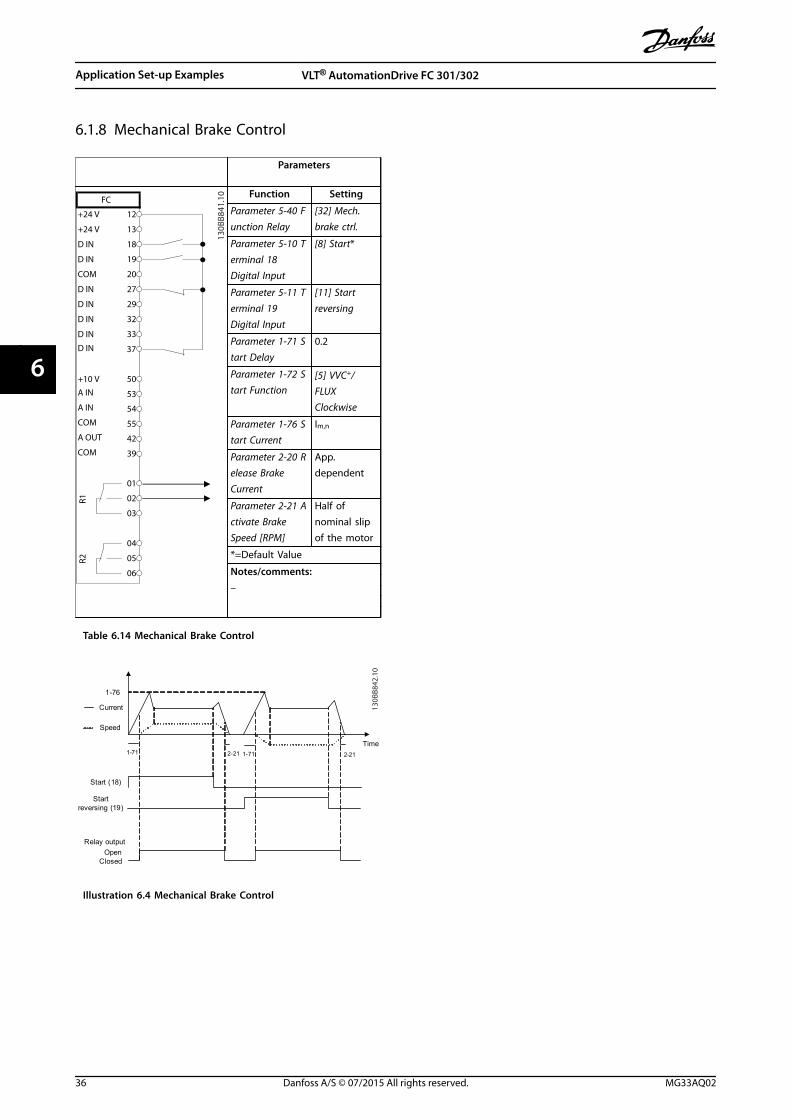
6.1.8 Mechanical Brake Control
Parameters
FC
+24 V
+24 V
D IN
D IN
D IN
COM
D IN
D IN
D IN
D IN
+10 V
A IN
A IN
COM
A OUT
COM
R1R2
12
13
18
19
20
27
29
32
33
37
50
53
54
55
42
39
01
02
03
04
05
06
130B
B841
.10 Function Setting
Parameter 5-40 Function Relay
[32] Mech.brake ctrl.
Parameter 5-10 Terminal 18Digital Input
[8] Start*
Parameter 5-11 Terminal 19Digital Input
[11] Startreversing
Parameter 1-71 Start Delay
0.2
Parameter 1-72 Start Function
[5] VVC+/FLUXClockwise
Parameter 1-76 Start Current
Im,n
Parameter 2-20 Release BrakeCurrent
App.dependent
Parameter 2-21 Activate BrakeSpeed [RPM]
Half ofnominal slipof the motor
*=Default Value
Notes/comments:–
Table 6.14 Mechanical Brake Control
Start (18)
Start reversing (19)
Relay output
Speed
Time
Current
1-71 1-712-21 2-21
1-76
OpenClosed
130B
B842
.10
Illustration 6.4 Mechanical Brake Control
Application Set-up Examples VLT® AutomationDrive FC 301/302
36 Danfoss A/S © 07/2015 All rights reserved. MG33AQ02
66
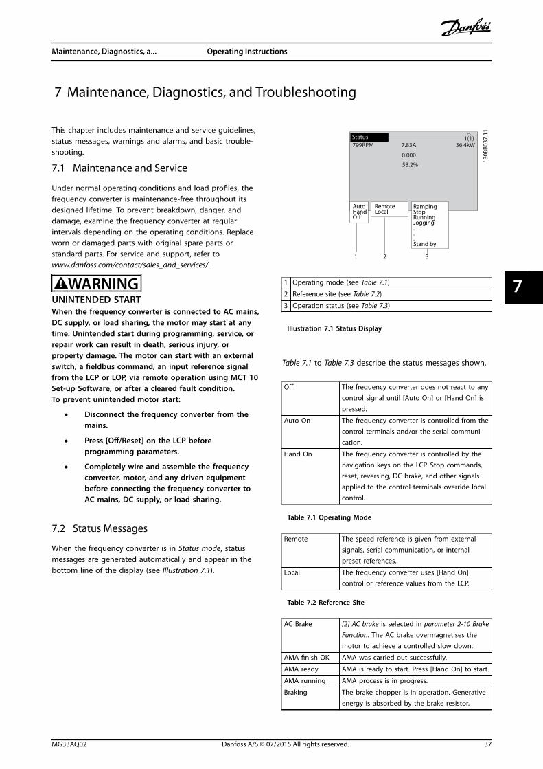
7 Maintenance, Diagnostics, and Troubleshooting
This chapter includes maintenance and service guidelines,status messages, warnings and alarms, and basic trouble-shooting.
7.1 Maintenance and Service
Under normal operating conditions and load profiles, thefrequency converter is maintenance-free throughout itsdesigned lifetime. To prevent breakdown, danger, anddamage, examine the frequency converter at regularintervals depending on the operating conditions. Replaceworn or damaged parts with original spare parts orstandard parts. For service and support, refer towww.danfoss.com/contact/sales_and_services/.
WARNINGUNINTENDED STARTWhen the frequency converter is connected to AC mains,DC supply, or load sharing, the motor may start at anytime. Unintended start during programming, service, orrepair work can result in death, serious injury, orproperty damage. The motor can start with an externalswitch, a fieldbus command, an input reference signalfrom the LCP or LOP, via remote operation using MCT 10Set-up Software, or after a cleared fault condition.To prevent unintended motor start:
• Disconnect the frequency converter from themains.
• Press [Off/Reset] on the LCP beforeprogramming parameters.
• Completely wire and assemble the frequencyconverter, motor, and any driven equipmentbefore connecting the frequency converter toAC mains, DC supply, or load sharing.
7.2 Status Messages
When the frequency converter is in Status mode, statusmessages are generated automatically and appear in thebottom line of the display (see Illustration 7.1).
Status799RPM 7.83A 36.4kW
0.000
53.2%
1(1)
AutoHandO
RemoteLocal
RampingStopRunningJogging...Stand by
130B
B037
.11
1 2 3
1 Operating mode (see Table 7.1)
2 Reference site (see Table 7.2)
3 Operation status (see Table 7.3)
Illustration 7.1 Status Display
Table 7.1 to Table 7.3 describe the status messages shown.
Off The frequency converter does not react to anycontrol signal until [Auto On] or [Hand On] ispressed.
Auto On The frequency converter is controlled from thecontrol terminals and/or the serial communi-cation.
Hand On The frequency converter is controlled by thenavigation keys on the LCP. Stop commands,reset, reversing, DC brake, and other signalsapplied to the control terminals override localcontrol.
Table 7.1 Operating Mode
Remote The speed reference is given from externalsignals, serial communication, or internalpreset references.
Local The frequency converter uses [Hand On]control or reference values from the LCP.
Table 7.2 Reference Site
AC Brake [2] AC brake is selected in parameter 2-10 BrakeFunction. The AC brake overmagnetises themotor to achieve a controlled slow down.
AMA finish OK AMA was carried out successfully.
AMA ready AMA is ready to start. Press [Hand On] to start.
AMA running AMA process is in progress.
Braking The brake chopper is in operation. Generativeenergy is absorbed by the brake resistor.
Maintenance, Diagnostics, a... Operating Instructions
MG33AQ02 Danfoss A/S © 07/2015 All rights reserved. 37
7 7
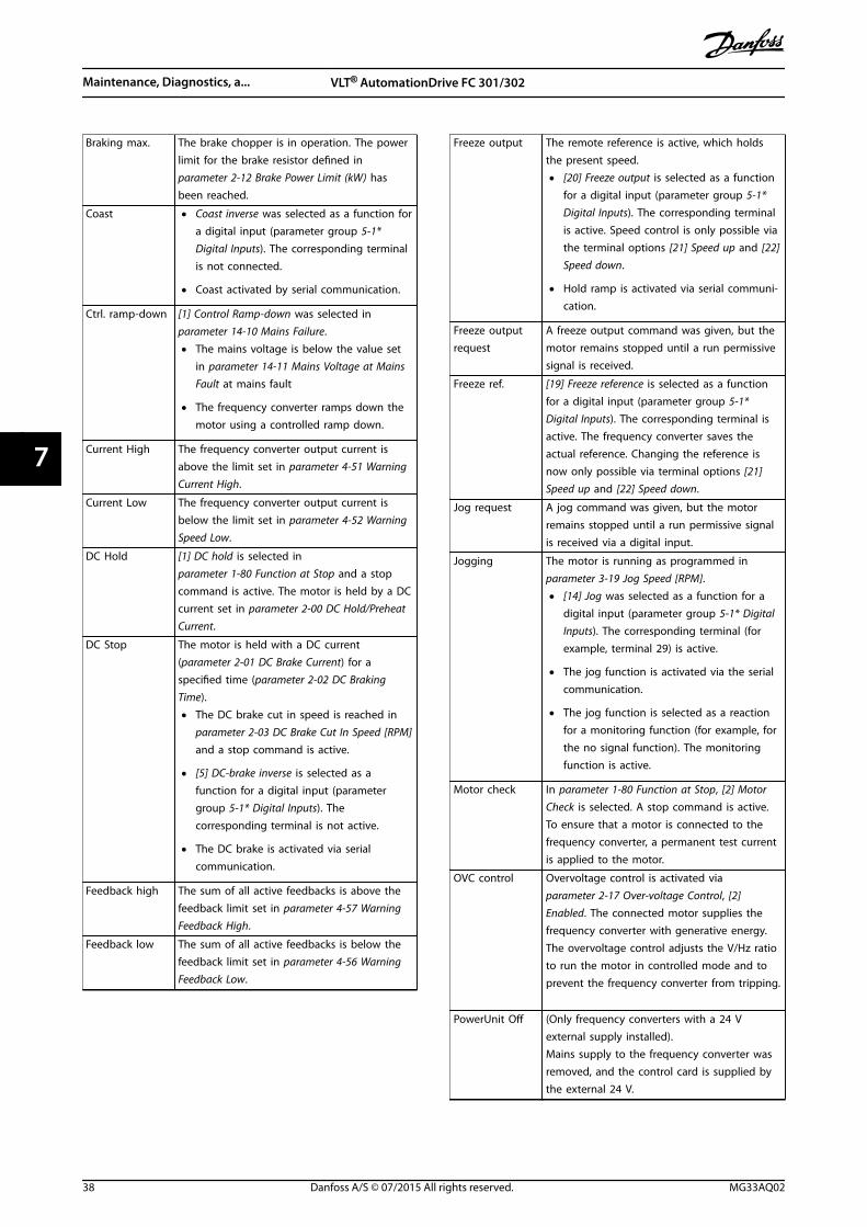
Braking max. The brake chopper is in operation. The powerlimit for the brake resistor defined inparameter 2-12 Brake Power Limit (kW) hasbeen reached.
Coast • Coast inverse was selected as a function fora digital input (parameter group 5-1*Digital Inputs). The corresponding terminalis not connected.
• Coast activated by serial communication.
Ctrl. ramp-down [1] Control Ramp-down was selected inparameter 14-10 Mains Failure.
• The mains voltage is below the value setin parameter 14-11 Mains Voltage at MainsFault at mains fault
• The frequency converter ramps down themotor using a controlled ramp down.
Current High The frequency converter output current isabove the limit set in parameter 4-51 WarningCurrent High.
Current Low The frequency converter output current isbelow the limit set in parameter 4-52 WarningSpeed Low.
DC Hold [1] DC hold is selected inparameter 1-80 Function at Stop and a stopcommand is active. The motor is held by a DCcurrent set in parameter 2-00 DC Hold/PreheatCurrent.
DC Stop The motor is held with a DC current(parameter 2-01 DC Brake Current) for aspecified time (parameter 2-02 DC BrakingTime).
• The DC brake cut in speed is reached inparameter 2-03 DC Brake Cut In Speed [RPM]and a stop command is active.
• [5] DC-brake inverse is selected as afunction for a digital input (parametergroup 5-1* Digital Inputs). Thecorresponding terminal is not active.
• The DC brake is activated via serialcommunication.
Feedback high The sum of all active feedbacks is above thefeedback limit set in parameter 4-57 WarningFeedback High.
Feedback low The sum of all active feedbacks is below thefeedback limit set in parameter 4-56 WarningFeedback Low.
Freeze output The remote reference is active, which holdsthe present speed.
• [20] Freeze output is selected as a functionfor a digital input (parameter group 5-1*Digital Inputs). The corresponding terminalis active. Speed control is only possible viathe terminal options [21] Speed up and [22]Speed down.
• Hold ramp is activated via serial communi-cation.
Freeze outputrequest
A freeze output command was given, but themotor remains stopped until a run permissivesignal is received.
Freeze ref. [19] Freeze reference is selected as a functionfor a digital input (parameter group 5-1*Digital Inputs). The corresponding terminal isactive. The frequency converter saves theactual reference. Changing the reference isnow only possible via terminal options [21]Speed up and [22] Speed down.
Jog request A jog command was given, but the motorremains stopped until a run permissive signalis received via a digital input.
Jogging The motor is running as programmed inparameter 3-19 Jog Speed [RPM].
• [14] Jog was selected as a function for adigital input (parameter group 5-1* DigitalInputs). The corresponding terminal (forexample, terminal 29) is active.
• The jog function is activated via the serialcommunication.
• The jog function is selected as a reactionfor a monitoring function (for example, forthe no signal function). The monitoringfunction is active.
Motor check In parameter 1-80 Function at Stop, [2] MotorCheck is selected. A stop command is active.To ensure that a motor is connected to thefrequency converter, a permanent test currentis applied to the motor.
OVC control Overvoltage control is activated viaparameter 2-17 Over-voltage Control, [2]Enabled. The connected motor supplies thefrequency converter with generative energy.The overvoltage control adjusts the V/Hz ratioto run the motor in controlled mode and toprevent the frequency converter from tripping.
PowerUnit Off (Only frequency converters with a 24 Vexternal supply installed).Mains supply to the frequency converter wasremoved, and the control card is supplied bythe external 24 V.
Maintenance, Diagnostics, a... VLT® AutomationDrive FC 301/302
38 Danfoss A/S © 07/2015 All rights reserved. MG33AQ02
77
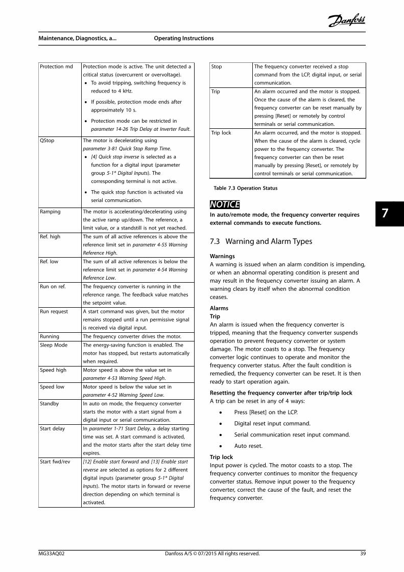
Protection md Protection mode is active. The unit detected acritical status (overcurrent or overvoltage).
• To avoid tripping, switching frequency isreduced to 4 kHz.
• If possible, protection mode ends afterapproximately 10 s.
• Protection mode can be restricted inparameter 14-26 Trip Delay at Inverter Fault.
QStop The motor is decelerating usingparameter 3-81 Quick Stop Ramp Time.
• [4] Quick stop inverse is selected as afunction for a digital input (parametergroup 5-1* Digital Inputs). Thecorresponding terminal is not active.
• The quick stop function is activated viaserial communication.
Ramping The motor is accelerating/decelerating usingthe active ramp up/down. The reference, alimit value, or a standstill is not yet reached.
Ref. high The sum of all active references is above thereference limit set in parameter 4-55 WarningReference High.
Ref. low The sum of all active references is below thereference limit set in parameter 4-54 WarningReference Low.
Run on ref. The frequency converter is running in thereference range. The feedback value matchesthe setpoint value.
Run request A start command was given, but the motorremains stopped until a run permissive signalis received via digital input.
Running The frequency converter drives the motor.
Sleep Mode The energy-saving function is enabled. Themotor has stopped, but restarts automaticallywhen required.
Speed high Motor speed is above the value set inparameter 4-53 Warning Speed High.
Speed low Motor speed is below the value set inparameter 4-52 Warning Speed Low.
Standby In auto on mode, the frequency converterstarts the motor with a start signal from adigital input or serial communication.
Start delay In parameter 1-71 Start Delay, a delay startingtime was set. A start command is activated,and the motor starts after the start delay timeexpires.
Start fwd/rev [12] Enable start forward and [13] Enable startreverse are selected as options for 2 differentdigital inputs (parameter group 5-1* DigitalInputs). The motor starts in forward or reversedirection depending on which terminal isactivated.
Stop The frequency converter received a stopcommand from the LCP, digital input, or serialcommunication.
Trip An alarm occurred and the motor is stopped.Once the cause of the alarm is cleared, thefrequency converter can be reset manually bypressing [Reset] or remotely by controlterminals or serial communication.
Trip lock An alarm occurred, and the motor is stopped.When the cause of the alarm is cleared, cyclepower to the frequency converter. Thefrequency converter can then be resetmanually by pressing [Reset], or remotely bycontrol terminals or serial communication.
Table 7.3 Operation Status
NOTICEIn auto/remote mode, the frequency converter requiresexternal commands to execute functions.
7.3 Warning and Alarm Types
WarningsA warning is issued when an alarm condition is impending,or when an abnormal operating condition is present andmay result in the frequency converter issuing an alarm. Awarning clears by itself when the abnormal conditionceases.
AlarmsTripAn alarm is issued when the frequency converter istripped, meaning that the frequency converter suspendsoperation to prevent frequency converter or systemdamage. The motor coasts to a stop. The frequencyconverter logic continues to operate and monitor thefrequency converter status. After the fault condition isremedied, the frequency converter can be reset. It is thenready to start operation again.
Resetting the frequency converter after trip/trip lockA trip can be reset in any of 4 ways:
• Press [Reset] on the LCP.
• Digital reset input command.
• Serial communication reset input command.
• Auto reset.
Trip lockInput power is cycled. The motor coasts to a stop. Thefrequency converter continues to monitor the frequencyconverter status. Remove input power to the frequencyconverter, correct the cause of the fault, and reset thefrequency converter.
Maintenance, Diagnostics, a... Operating Instructions
MG33AQ02 Danfoss A/S © 07/2015 All rights reserved. 39
7 7
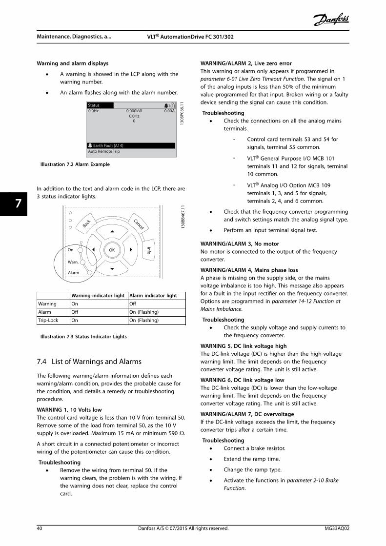
Warning and alarm displays
• A warning is showed in the LCP along with thewarning number.
• An alarm flashes along with the alarm number.
130B
P086
.11
Status0.0Hz 0.000kW 0.00A
0.0Hz0
Earth Fault [A14]Auto Remote Trip
1(1)
Illustration 7.2 Alarm Example
In addition to the text and alarm code in the LCP, there are3 status indicator lights.
Back
CancelInfoOKOn
Alarm
Warn.
130B
B467
.11
Warning indicator light Alarm indicator light
Warning On Off
Alarm Off On (Flashing)
Trip-Lock On On (Flashing)
Illustration 7.3 Status Indicator Lights
7.4 List of Warnings and Alarms
The following warning/alarm information defines eachwarning/alarm condition, provides the probable cause forthe condition, and details a remedy or troubleshootingprocedure.
WARNING 1, 10 Volts lowThe control card voltage is less than 10 V from terminal 50.Remove some of the load from terminal 50, as the 10 Vsupply is overloaded. Maximum 15 mA or minimum 590 Ω.
A short circuit in a connected potentiometer or incorrectwiring of the potentiometer can cause this condition.
Troubleshooting• Remove the wiring from terminal 50. If the
warning clears, the problem is with the wiring. Ifthe warning does not clear, replace the controlcard.
WARNING/ALARM 2, Live zero errorThis warning or alarm only appears if programmed inparameter 6-01 Live Zero Timeout Function. The signal on 1of the analog inputs is less than 50% of the minimumvalue programmed for that input. Broken wiring or a faultydevice sending the signal can cause this condition.
Troubleshooting• Check the connections on all the analog mains
terminals.
- Control card terminals 53 and 54 forsignals, terminal 55 common.
- VLT® General Purpose I/O MCB 101terminals 11 and 12 for signals, terminal10 common.
- VLT® Analog I/O Option MCB 109terminals 1, 3, and 5 for signals,terminals 2, 4, and 6 common.
• Check that the frequency converter programmingand switch settings match the analog signal type.
• Perform an input terminal signal test.
WARNING/ALARM 3, No motorNo motor is connected to the output of the frequencyconverter.
WARNING/ALARM 4, Mains phase lossA phase is missing on the supply side, or the mainsvoltage imbalance is too high. This message also appearsfor a fault in the input rectifier on the frequency converter.Options are programmed in parameter 14-12 Function atMains Imbalance.
Troubleshooting• Check the supply voltage and supply currents to
the frequency converter.
WARNING 5, DC link voltage highThe DC-link voltage (DC) is higher than the high-voltagewarning limit. The limit depends on the frequencyconverter voltage rating. The unit is still active.
WARNING 6, DC link voltage lowThe DC-link voltage (DC) is lower than the low-voltagewarning limit. The limit depends on the frequencyconverter voltage rating. The unit is still active.
WARNING/ALARM 7, DC overvoltageIf the DC-link voltage exceeds the limit, the frequencyconverter trips after a certain time.
Troubleshooting• Connect a brake resistor.
• Extend the ramp time.
• Change the ramp type.
• Activate the functions in parameter 2-10 BrakeFunction.
Maintenance, Diagnostics, a... VLT® AutomationDrive FC 301/302
40 Danfoss A/S © 07/2015 All rights reserved. MG33AQ02
77
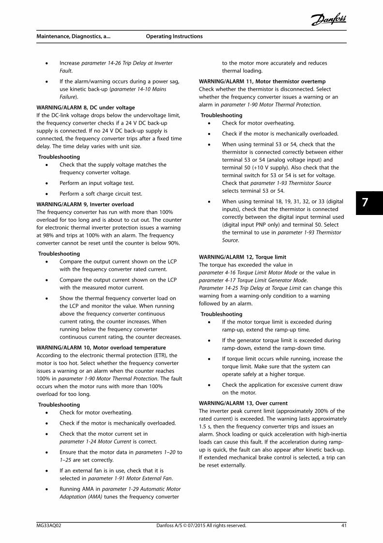
• Increase parameter 14-26 Trip Delay at InverterFault.
• If the alarm/warning occurs during a power sag,use kinetic back-up (parameter 14-10 MainsFailure).
WARNING/ALARM 8, DC under voltageIf the DC-link voltage drops below the undervoltage limit,the frequency converter checks if a 24 V DC back-upsupply is connected. If no 24 V DC back-up supply isconnected, the frequency converter trips after a fixed timedelay. The time delay varies with unit size.
Troubleshooting• Check that the supply voltage matches the
frequency converter voltage.
• Perform an input voltage test.
• Perform a soft charge circuit test.
WARNING/ALARM 9, Inverter overloadThe frequency converter has run with more than 100%overload for too long and is about to cut out. The counterfor electronic thermal inverter protection issues a warningat 98% and trips at 100% with an alarm. The frequencyconverter cannot be reset until the counter is below 90%.
Troubleshooting• Compare the output current shown on the LCP
with the frequency converter rated current.
• Compare the output current shown on the LCPwith the measured motor current.
• Show the thermal frequency converter load onthe LCP and monitor the value. When runningabove the frequency converter continuouscurrent rating, the counter increases. Whenrunning below the frequency convertercontinuous current rating, the counter decreases.
WARNING/ALARM 10, Motor overload temperatureAccording to the electronic thermal protection (ETR), themotor is too hot. Select whether the frequency converterissues a warning or an alarm when the counter reaches100% in parameter 1-90 Motor Thermal Protection. The faultoccurs when the motor runs with more than 100%overload for too long.
Troubleshooting• Check for motor overheating.
• Check if the motor is mechanically overloaded.
• Check that the motor current set inparameter 1-24 Motor Current is correct.
• Ensure that the motor data in parameters 1–20 to1–25 are set correctly.
• If an external fan is in use, check that it isselected in parameter 1-91 Motor External Fan.
• Running AMA in parameter 1-29 Automatic MotorAdaptation (AMA) tunes the frequency converter
to the motor more accurately and reducesthermal loading.
WARNING/ALARM 11, Motor thermistor overtempCheck whether the thermistor is disconnected. Selectwhether the frequency converter issues a warning or analarm in parameter 1-90 Motor Thermal Protection.
Troubleshooting• Check for motor overheating.
• Check if the motor is mechanically overloaded.
• When using terminal 53 or 54, check that thethermistor is connected correctly between eitherterminal 53 or 54 (analog voltage input) andterminal 50 (+10 V supply). Also check that theterminal switch for 53 or 54 is set for voltage.Check that parameter 1-93 Thermistor Sourceselects terminal 53 or 54.
• When using terminal 18, 19, 31, 32, or 33 (digitalinputs), check that the thermistor is connectedcorrectly between the digital input terminal used(digital input PNP only) and terminal 50. Selectthe terminal to use in parameter 1-93 ThermistorSource.
WARNING/ALARM 12, Torque limitThe torque has exceeded the value inparameter 4-16 Torque Limit Motor Mode or the value inparameter 4-17 Torque Limit Generator Mode.Parameter 14-25 Trip Delay at Torque Limit can change thiswarning from a warning-only condition to a warningfollowed by an alarm.
Troubleshooting• If the motor torque limit is exceeded during
ramp-up, extend the ramp-up time.
• If the generator torque limit is exceeded duringramp-down, extend the ramp-down time.
• If torque limit occurs while running, increase thetorque limit. Make sure that the system canoperate safely at a higher torque.
• Check the application for excessive current drawon the motor.
WARNING/ALARM 13, Over currentThe inverter peak current limit (approximately 200% of therated current) is exceeded. The warning lasts approximately1.5 s, then the frequency converter trips and issues analarm. Shock loading or quick acceleration with high-inertialoads can cause this fault. If the acceleration during ramp-up is quick, the fault can also appear after kinetic back-up.If extended mechanical brake control is selected, a trip canbe reset externally.
Maintenance, Diagnostics, a... Operating Instructions
MG33AQ02 Danfoss A/S © 07/2015 All rights reserved. 41
7 7
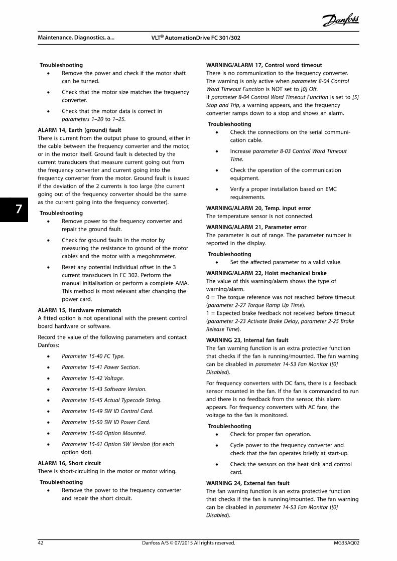
Troubleshooting• Remove the power and check if the motor shaft
can be turned.
• Check that the motor size matches the frequencyconverter.
• Check that the motor data is correct inparameters 1–20 to 1–25.
ALARM 14, Earth (ground) faultThere is current from the output phase to ground, either inthe cable between the frequency converter and the motor,or in the motor itself. Ground fault is detected by thecurrent transducers that measure current going out fromthe frequency converter and current going into thefrequency converter from the motor. Ground fault is issuedif the deviation of the 2 currents is too large (the currentgoing out of the frequency converter should be the sameas the current going into the frequency converter).
Troubleshooting• Remove power to the frequency converter and
repair the ground fault.
• Check for ground faults in the motor bymeasuring the resistance to ground of the motorcables and the motor with a megohmmeter.
• Reset any potential individual offset in the 3current transducers in FC 302. Perform themanual initialisation or perform a complete AMA.This method is most relevant after changing thepower card.
ALARM 15, Hardware mismatchA fitted option is not operational with the present controlboard hardware or software.
Record the value of the following parameters and contactDanfoss:
• Parameter 15-40 FC Type.
• Parameter 15-41 Power Section.
• Parameter 15-42 Voltage.
• Parameter 15-43 Software Version.
• Parameter 15-45 Actual Typecode String.
• Parameter 15-49 SW ID Control Card.
• Parameter 15-50 SW ID Power Card.
• Parameter 15-60 Option Mounted.
• Parameter 15-61 Option SW Version (for eachoption slot).
ALARM 16, Short circuitThere is short-circuiting in the motor or motor wiring.
Troubleshooting• Remove the power to the frequency converter
and repair the short circuit.
WARNING/ALARM 17, Control word timeoutThere is no communication to the frequency converter.The warning is only active when parameter 8-04 ControlWord Timeout Function is NOT set to [0] Off.If parameter 8-04 Control Word Timeout Function is set to [5]Stop and Trip, a warning appears, and the frequencyconverter ramps down to a stop and shows an alarm.
Troubleshooting• Check the connections on the serial communi-
cation cable.
• Increase parameter 8-03 Control Word TimeoutTime.
• Check the operation of the communicationequipment.
• Verify a proper installation based on EMCrequirements.
WARNING/ALARM 20, Temp. input errorThe temperature sensor is not connected.
WARNING/ALARM 21, Parameter errorThe parameter is out of range. The parameter number isreported in the display.
Troubleshooting• Set the affected parameter to a valid value.
WARNING/ALARM 22, Hoist mechanical brakeThe value of this warning/alarm shows the type ofwarning/alarm.0 = The torque reference was not reached before timeout(parameter 2-27 Torque Ramp Up Time).1 = Expected brake feedback not received before timeout(parameter 2-23 Activate Brake Delay, parameter 2-25 BrakeRelease Time).
WARNING 23, Internal fan faultThe fan warning function is an extra protective functionthat checks if the fan is running/mounted. The fan warningcan be disabled in parameter 14-53 Fan Monitor ([0]Disabled).
For frequency converters with DC fans, there is a feedbacksensor mounted in the fan. If the fan is commanded to runand there is no feedback from the sensor, this alarmappears. For frequency converters with AC fans, thevoltage to the fan is monitored.
Troubleshooting• Check for proper fan operation.
• Cycle power to the frequency converter andcheck that the fan operates briefly at start-up.
• Check the sensors on the heat sink and controlcard.
WARNING 24, External fan faultThe fan warning function is an extra protective functionthat checks if the fan is running/mounted. The fan warningcan be disabled in parameter 14-53 Fan Monitor ([0]Disabled).
Maintenance, Diagnostics, a... VLT® AutomationDrive FC 301/302
42 Danfoss A/S © 07/2015 All rights reserved. MG33AQ02
77
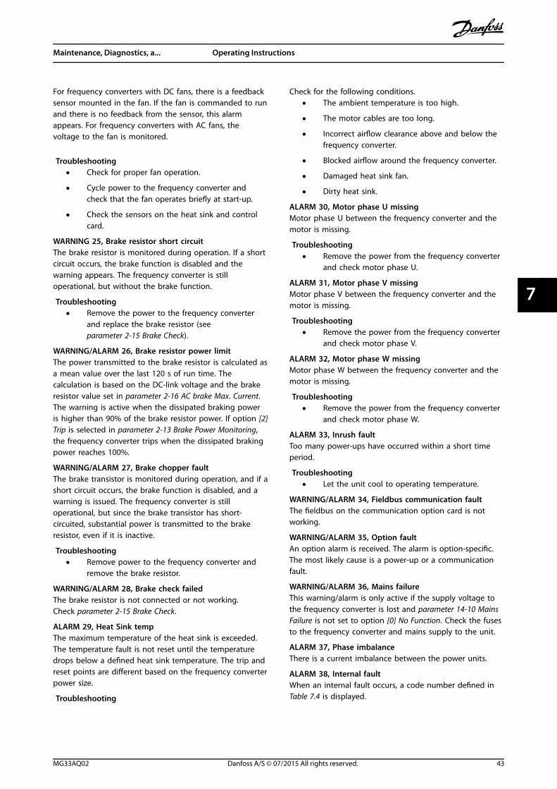
For frequency converters with DC fans, there is a feedbacksensor mounted in the fan. If the fan is commanded to runand there is no feedback from the sensor, this alarmappears. For frequency converters with AC fans, thevoltage to the fan is monitored.
Troubleshooting• Check for proper fan operation.
• Cycle power to the frequency converter andcheck that the fan operates briefly at start-up.
• Check the sensors on the heat sink and controlcard.
WARNING 25, Brake resistor short circuitThe brake resistor is monitored during operation. If a shortcircuit occurs, the brake function is disabled and thewarning appears. The frequency converter is stilloperational, but without the brake function.
Troubleshooting• Remove the power to the frequency converter
and replace the brake resistor (seeparameter 2-15 Brake Check).
WARNING/ALARM 26, Brake resistor power limitThe power transmitted to the brake resistor is calculated asa mean value over the last 120 s of run time. Thecalculation is based on the DC-link voltage and the brakeresistor value set in parameter 2-16 AC brake Max. Current.The warning is active when the dissipated braking poweris higher than 90% of the brake resistor power. If option [2]Trip is selected in parameter 2-13 Brake Power Monitoring,the frequency converter trips when the dissipated brakingpower reaches 100%.
WARNING/ALARM 27, Brake chopper faultThe brake transistor is monitored during operation, and if ashort circuit occurs, the brake function is disabled, and awarning is issued. The frequency converter is stilloperational, but since the brake transistor has short-circuited, substantial power is transmitted to the brakeresistor, even if it is inactive.
Troubleshooting• Remove power to the frequency converter and
remove the brake resistor.
WARNING/ALARM 28, Brake check failedThe brake resistor is not connected or not working.Check parameter 2-15 Brake Check.
ALARM 29, Heat Sink tempThe maximum temperature of the heat sink is exceeded.The temperature fault is not reset until the temperaturedrops below a defined heat sink temperature. The trip andreset points are different based on the frequency converterpower size.
Troubleshooting
Check for the following conditions.• The ambient temperature is too high.
• The motor cables are too long.
• Incorrect airflow clearance above and below thefrequency converter.
• Blocked airflow around the frequency converter.
• Damaged heat sink fan.
• Dirty heat sink.
ALARM 30, Motor phase U missingMotor phase U between the frequency converter and themotor is missing.
Troubleshooting• Remove the power from the frequency converter
and check motor phase U.
ALARM 31, Motor phase V missingMotor phase V between the frequency converter and themotor is missing.
Troubleshooting• Remove the power from the frequency converter
and check motor phase V.
ALARM 32, Motor phase W missingMotor phase W between the frequency converter and themotor is missing.
Troubleshooting• Remove the power from the frequency converter
and check motor phase W.
ALARM 33, Inrush faultToo many power-ups have occurred within a short timeperiod.
Troubleshooting• Let the unit cool to operating temperature.
WARNING/ALARM 34, Fieldbus communication faultThe fieldbus on the communication option card is notworking.
WARNING/ALARM 35, Option faultAn option alarm is received. The alarm is option-specific.The most likely cause is a power-up or a communicationfault.
WARNING/ALARM 36, Mains failureThis warning/alarm is only active if the supply voltage tothe frequency converter is lost and parameter 14-10 MainsFailure is not set to option [0] No Function. Check the fusesto the frequency converter and mains supply to the unit.
ALARM 37, Phase imbalanceThere is a current imbalance between the power units.
ALARM 38, Internal faultWhen an internal fault occurs, a code number defined inTable 7.4 is displayed.
Maintenance, Diagnostics, a... Operating Instructions
MG33AQ02 Danfoss A/S © 07/2015 All rights reserved. 43
7 7
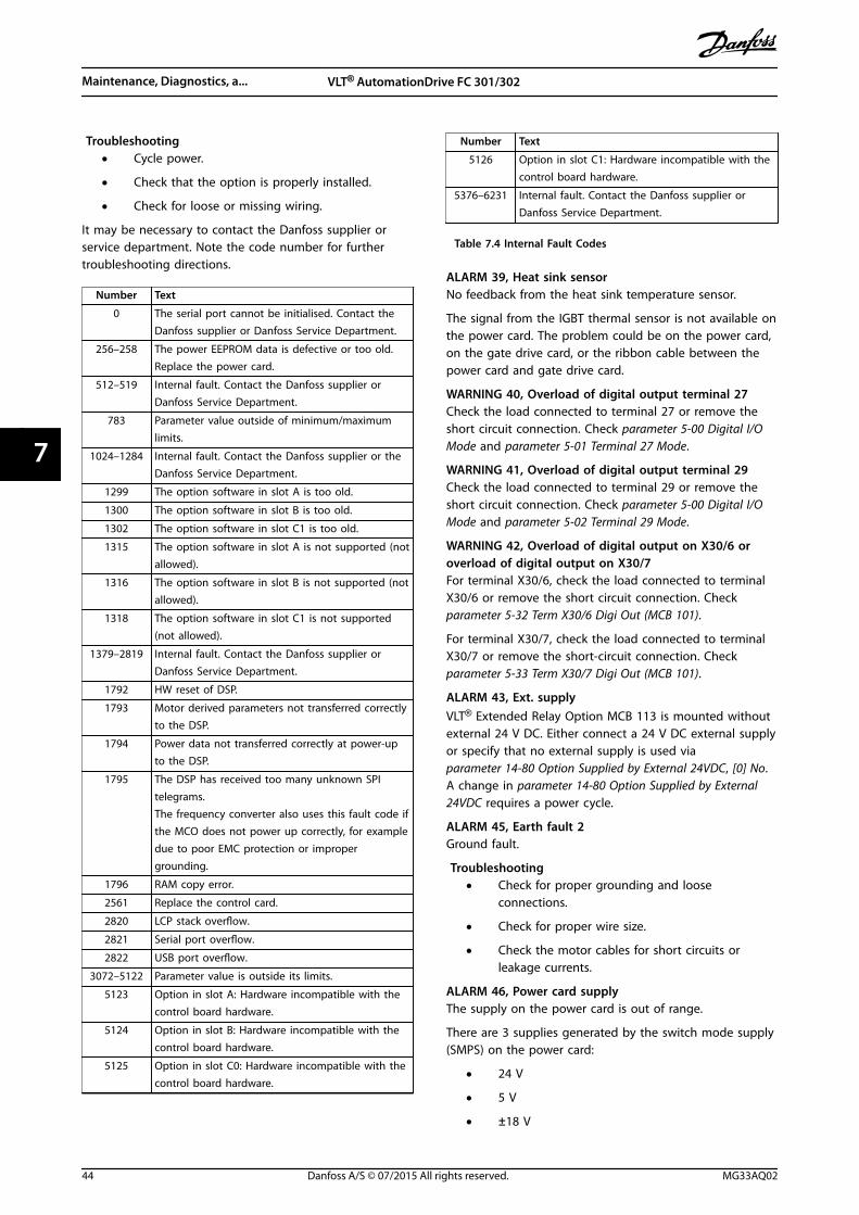
Troubleshooting• Cycle power.
• Check that the option is properly installed.
• Check for loose or missing wiring.
It may be necessary to contact the Danfoss supplier orservice department. Note the code number for furthertroubleshooting directions.
Number Text
0 The serial port cannot be initialised. Contact theDanfoss supplier or Danfoss Service Department.
256–258 The power EEPROM data is defective or too old.Replace the power card.
512–519 Internal fault. Contact the Danfoss supplier orDanfoss Service Department.
783 Parameter value outside of minimum/maximumlimits.
1024–1284 Internal fault. Contact the Danfoss supplier or theDanfoss Service Department.
1299 The option software in slot A is too old.
1300 The option software in slot B is too old.
1302 The option software in slot C1 is too old.
1315 The option software in slot A is not supported (notallowed).
1316 The option software in slot B is not supported (notallowed).
1318 The option software in slot C1 is not supported(not allowed).
1379–2819 Internal fault. Contact the Danfoss supplier orDanfoss Service Department.
1792 HW reset of DSP.
1793 Motor derived parameters not transferred correctlyto the DSP.
1794 Power data not transferred correctly at power-upto the DSP.
1795 The DSP has received too many unknown SPItelegrams.The frequency converter also uses this fault code ifthe MCO does not power up correctly, for exampledue to poor EMC protection or impropergrounding.
1796 RAM copy error.
2561 Replace the control card.
2820 LCP stack overflow.
2821 Serial port overflow.
2822 USB port overflow.
3072–5122 Parameter value is outside its limits.
5123 Option in slot A: Hardware incompatible with thecontrol board hardware.
5124 Option in slot B: Hardware incompatible with thecontrol board hardware.
5125 Option in slot C0: Hardware incompatible with thecontrol board hardware.
Number Text
5126 Option in slot C1: Hardware incompatible with thecontrol board hardware.
5376–6231 Internal fault. Contact the Danfoss supplier orDanfoss Service Department.
Table 7.4 Internal Fault Codes
ALARM 39, Heat sink sensorNo feedback from the heat sink temperature sensor.
The signal from the IGBT thermal sensor is not available onthe power card. The problem could be on the power card,on the gate drive card, or the ribbon cable between thepower card and gate drive card.
WARNING 40, Overload of digital output terminal 27Check the load connected to terminal 27 or remove theshort circuit connection. Check parameter 5-00 Digital I/OMode and parameter 5-01 Terminal 27 Mode.
WARNING 41, Overload of digital output terminal 29Check the load connected to terminal 29 or remove theshort circuit connection. Check parameter 5-00 Digital I/OMode and parameter 5-02 Terminal 29 Mode.
WARNING 42, Overload of digital output on X30/6 oroverload of digital output on X30/7For terminal X30/6, check the load connected to terminalX30/6 or remove the short circuit connection. Checkparameter 5-32 Term X30/6 Digi Out (MCB 101).
For terminal X30/7, check the load connected to terminalX30/7 or remove the short-circuit connection. Checkparameter 5-33 Term X30/7 Digi Out (MCB 101).
ALARM 43, Ext. supplyVLT® Extended Relay Option MCB 113 is mounted withoutexternal 24 V DC. Either connect a 24 V DC external supplyor specify that no external supply is used viaparameter 14-80 Option Supplied by External 24VDC, [0] No.A change in parameter 14-80 Option Supplied by External24VDC requires a power cycle.
ALARM 45, Earth fault 2Ground fault.
Troubleshooting• Check for proper grounding and loose
connections.
• Check for proper wire size.
• Check the motor cables for short circuits orleakage currents.
ALARM 46, Power card supplyThe supply on the power card is out of range.
There are 3 supplies generated by the switch mode supply(SMPS) on the power card:
• 24 V
• 5 V
• ±18 V
Maintenance, Diagnostics, a... VLT® AutomationDrive FC 301/302
44 Danfoss A/S © 07/2015 All rights reserved. MG33AQ02
77
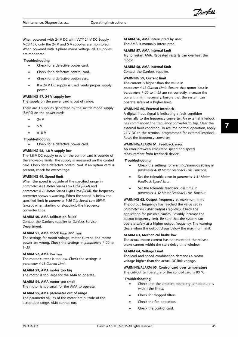
When powered with 24 V DC with VLT® 24 V DC SupplyMCB 107, only the 24 V and 5 V supplies are monitored.When powered with 3-phase mains voltage, all 3 suppliesare monitored.
Troubleshooting• Check for a defective power card.
• Check for a defective control card.
• Check for a defective option card.
• If a 24 V DC supply is used, verify proper supplypower.
WARNING 47, 24 V supply lowThe supply on the power card is out of range.
There are 3 supplies generated by the switch mode supply(SMPS) on the power card:
• 24 V
• 5 V
• ±18 V
Troubleshooting• Check for a defective power card.
WARNING 48, 1.8 V supply lowThe 1.8 V DC supply used on the control card is outside ofthe allowable limits. The supply is measured on the controlcard. Check for a defective control card. If an option card ispresent, check for overvoltage.
WARNING 49, Speed limitWhen the speed is outside of the specified range inparameter 4-11 Motor Speed Low Limit [RPM] andparameter 4-13 Motor Speed High Limit [RPM], the frequencyconverter shows a warning. When the speed is below thespecified limit in parameter 1-86 Trip Speed Low [RPM](except when starting or stopping), the frequencyconverter trips.
ALARM 50, AMA calibration failedContact the Danfoss supplier or Danfoss ServiceDepartment.
ALARM 51, AMA check Unom and Inom
The settings for motor voltage, motor current, and motorpower are wrong. Check the settings in parameters 1–20 to1–25.
ALARM 52, AMA low Inom
The motor current is too low. Check the settings inparameter 4-18 Current Limit.
ALARM 53, AMA motor too bigThe motor is too large for the AMA to operate.
ALARM 54, AMA motor too smallThe motor is too small for the AMA to operate.
ALARM 55, AMA parameter out of rangeThe parameter values of the motor are outside of theacceptable range. AMA cannot run.
ALARM 56, AMA interrupted by userThe AMA is manually interrupted.
ALARM 57, AMA internal faultTry to restart AMA. Repeated restarts can overheat themotor.
ALARM 58, AMA Internal faultContact the Danfoss supplier.
WARNING 59, Current limitThe current is higher than the value inparameter 4-18 Current Limit. Ensure that motor data inparameters 1–20 to 1–25 are set correctly. Increase thecurrent limit if necessary. Ensure that the system canoperate safely at a higher limit.
WARNING 60, External interlockA digital input signal is indicating a fault conditionexternally to the frequency converter. An external interlockhas commanded the frequency converter to trip. Clear theexternal fault condition. To resume normal operation, apply24 V DC to the terminal programmed for external interlock.Reset the frequency converter.
WARNING/ALARM 61, Feedback errorAn error between calculated speed and speedmeasurement from feedback device.
Troubleshooting• Check the settings for warning/alarm/disabling in
parameter 4-30 Motor Feedback Loss Function.
• Set the tolerable error in parameter 4-31 MotorFeedback Speed Error.
• Set the tolerable feedback loss time inparameter 4-32 Motor Feedback Loss Timeout.
WARNING 62, Output frequency at maximum limitThe output frequency has reached the value set inparameter 4-19 Max Output Frequency. Check theapplication for possible causes. Possibly increase theoutput frequency limit. Be sure that the system canoperate safely at a higher output frequency. The warningclears when the output drops below the maximum limit.
ALARM 63, Mechanical brake lowThe actual motor current has not exceeded the releasebrake current within the start delay time window.
ALARM 64, Voltage LimitThe load and speed combination demands a motorvoltage higher than the actual DC-link voltage.
WARNING/ALARM 65, Control card over temperatureThe cut-out temperature of the control card is 80 °C.
Troubleshooting• Check that the ambient operating temperature is
within the limits.
• Check for clogged filters.
• Check the fan operation.
• Check the control card.
Maintenance, Diagnostics, a... Operating Instructions
MG33AQ02 Danfoss A/S © 07/2015 All rights reserved. 45
7 7
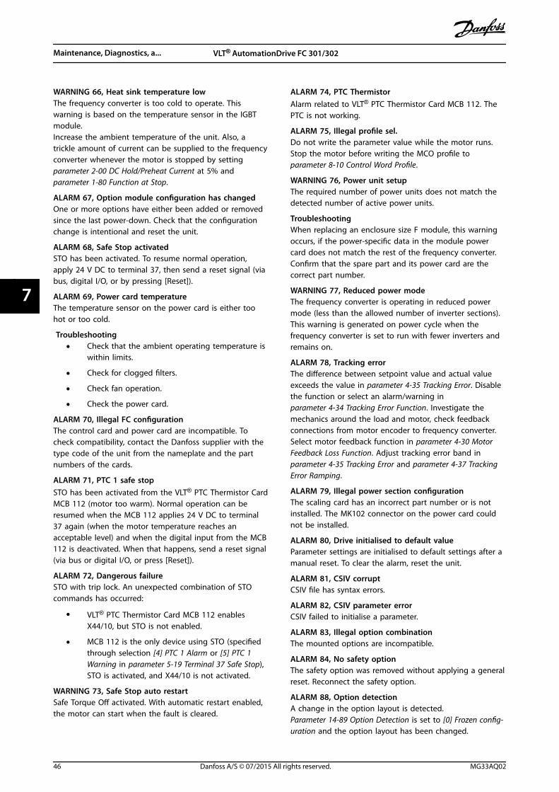
WARNING 66, Heat sink temperature lowThe frequency converter is too cold to operate. Thiswarning is based on the temperature sensor in the IGBTmodule.Increase the ambient temperature of the unit. Also, atrickle amount of current can be supplied to the frequencyconverter whenever the motor is stopped by settingparameter 2-00 DC Hold/Preheat Current at 5% andparameter 1-80 Function at Stop.
ALARM 67, Option module configuration has changedOne or more options have either been added or removedsince the last power-down. Check that the configurationchange is intentional and reset the unit.
ALARM 68, Safe Stop activatedSTO has been activated. To resume normal operation,apply 24 V DC to terminal 37, then send a reset signal (viabus, digital I/O, or by pressing [Reset]).
ALARM 69, Power card temperatureThe temperature sensor on the power card is either toohot or too cold.
Troubleshooting• Check that the ambient operating temperature is
within limits.
• Check for clogged filters.
• Check fan operation.
• Check the power card.
ALARM 70, Illegal FC configurationThe control card and power card are incompatible. Tocheck compatibility, contact the Danfoss supplier with thetype code of the unit from the nameplate and the partnumbers of the cards.
ALARM 71, PTC 1 safe stopSTO has been activated from the VLT® PTC Thermistor CardMCB 112 (motor too warm). Normal operation can beresumed when the MCB 112 applies 24 V DC to terminal37 again (when the motor temperature reaches anacceptable level) and when the digital input from the MCB112 is deactivated. When that happens, send a reset signal(via bus or digital I/O, or press [Reset]).
ALARM 72, Dangerous failureSTO with trip lock. An unexpected combination of STOcommands has occurred:
• VLT® PTC Thermistor Card MCB 112 enablesX44/10, but STO is not enabled.
• MCB 112 is the only device using STO (specifiedthrough selection [4] PTC 1 Alarm or [5] PTC 1Warning in parameter 5-19 Terminal 37 Safe Stop),STO is activated, and X44/10 is not activated.
WARNING 73, Safe Stop auto restartSafe Torque Off activated. With automatic restart enabled,the motor can start when the fault is cleared.
ALARM 74, PTC ThermistorAlarm related to VLT® PTC Thermistor Card MCB 112. ThePTC is not working.
ALARM 75, Illegal profile sel.Do not write the parameter value while the motor runs.Stop the motor before writing the MCO profile toparameter 8-10 Control Word Profile.
WARNING 76, Power unit setupThe required number of power units does not match thedetected number of active power units.
TroubleshootingWhen replacing an enclosure size F module, this warningoccurs, if the power-specific data in the module powercard does not match the rest of the frequency converter.Confirm that the spare part and its power card are thecorrect part number.
WARNING 77, Reduced power modeThe frequency converter is operating in reduced powermode (less than the allowed number of inverter sections).This warning is generated on power cycle when thefrequency converter is set to run with fewer inverters andremains on.
ALARM 78, Tracking errorThe difference between setpoint value and actual valueexceeds the value in parameter 4-35 Tracking Error. Disablethe function or select an alarm/warning inparameter 4-34 Tracking Error Function. Investigate themechanics around the load and motor, check feedbackconnections from motor encoder to frequency converter.Select motor feedback function in parameter 4-30 MotorFeedback Loss Function. Adjust tracking error band inparameter 4-35 Tracking Error and parameter 4-37 TrackingError Ramping.
ALARM 79, Illegal power section configurationThe scaling card has an incorrect part number or is notinstalled. The MK102 connector on the power card couldnot be installed.
ALARM 80, Drive initialised to default valueParameter settings are initialised to default settings after amanual reset. To clear the alarm, reset the unit.
ALARM 81, CSIV corruptCSIV file has syntax errors.
ALARM 82, CSIV parameter errorCSIV failed to initialise a parameter.
ALARM 83, Illegal option combinationThe mounted options are incompatible.
ALARM 84, No safety optionThe safety option was removed without applying a generalreset. Reconnect the safety option.
ALARM 88, Option detectionA change in the option layout is detected.Parameter 14-89 Option Detection is set to [0] Frozen config-uration and the option layout has been changed.
Maintenance, Diagnostics, a... VLT® AutomationDrive FC 301/302
46 Danfoss A/S © 07/2015 All rights reserved. MG33AQ02
77
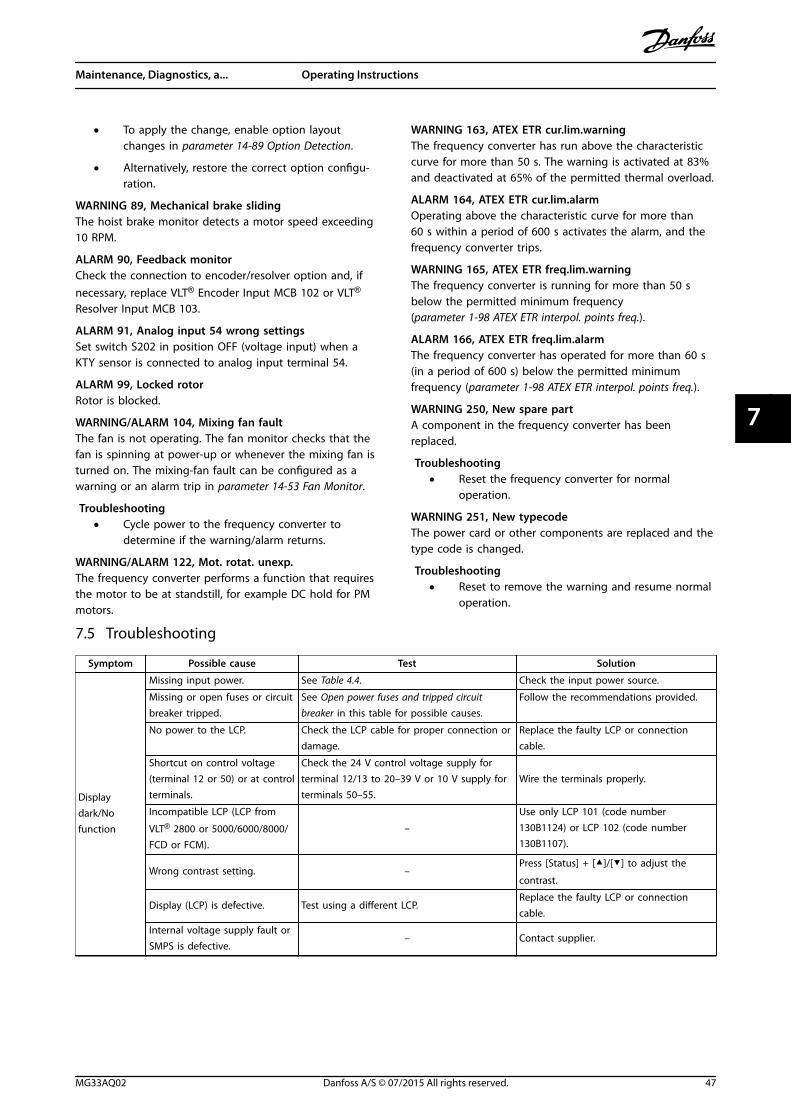
• To apply the change, enable option layoutchanges in parameter 14-89 Option Detection.
• Alternatively, restore the correct option configu-ration.
WARNING 89, Mechanical brake slidingThe hoist brake monitor detects a motor speed exceeding10 RPM.
ALARM 90, Feedback monitorCheck the connection to encoder/resolver option and, ifnecessary, replace VLT® Encoder Input MCB 102 or VLT®
Resolver Input MCB 103.
ALARM 91, Analog input 54 wrong settingsSet switch S202 in position OFF (voltage input) when aKTY sensor is connected to analog input terminal 54.
ALARM 99, Locked rotorRotor is blocked.
WARNING/ALARM 104, Mixing fan faultThe fan is not operating. The fan monitor checks that thefan is spinning at power-up or whenever the mixing fan isturned on. The mixing-fan fault can be configured as awarning or an alarm trip in parameter 14-53 Fan Monitor.
Troubleshooting• Cycle power to the frequency converter to
determine if the warning/alarm returns.
WARNING/ALARM 122, Mot. rotat. unexp.The frequency converter performs a function that requiresthe motor to be at standstill, for example DC hold for PMmotors.
WARNING 163, ATEX ETR cur.lim.warningThe frequency converter has run above the characteristiccurve for more than 50 s. The warning is activated at 83%and deactivated at 65% of the permitted thermal overload.
ALARM 164, ATEX ETR cur.lim.alarmOperating above the characteristic curve for more than60 s within a period of 600 s activates the alarm, and thefrequency converter trips.
WARNING 165, ATEX ETR freq.lim.warningThe frequency converter is running for more than 50 sbelow the permitted minimum frequency(parameter 1-98 ATEX ETR interpol. points freq.).
ALARM 166, ATEX ETR freq.lim.alarmThe frequency converter has operated for more than 60 s(in a period of 600 s) below the permitted minimumfrequency (parameter 1-98 ATEX ETR interpol. points freq.).
WARNING 250, New spare partA component in the frequency converter has beenreplaced.
Troubleshooting• Reset the frequency converter for normal
operation.
WARNING 251, New typecodeThe power card or other components are replaced and thetype code is changed.
Troubleshooting• Reset to remove the warning and resume normal
operation.
7.5 Troubleshooting
Symptom Possible cause Test Solution
Displaydark/Nofunction
Missing input power. See Table 4.4. Check the input power source.
Missing or open fuses or circuitbreaker tripped.
See Open power fuses and tripped circuitbreaker in this table for possible causes.
Follow the recommendations provided.
No power to the LCP. Check the LCP cable for proper connection ordamage.
Replace the faulty LCP or connectioncable.
Shortcut on control voltage(terminal 12 or 50) or at controlterminals.
Check the 24 V control voltage supply forterminal 12/13 to 20–39 V or 10 V supply forterminals 50–55.
Wire the terminals properly.
Incompatible LCP (LCP from
VLT® 2800 or 5000/6000/8000/FCD or FCM).
–
Use only LCP 101 (code number130B1124) or LCP 102 (code number130B1107).
Wrong contrast setting. –Press [Status] + []/[] to adjust the
contrast.
Display (LCP) is defective. Test using a different LCP.Replace the faulty LCP or connectioncable.
Internal voltage supply fault orSMPS is defective.
– Contact supplier.
Maintenance, Diagnostics, a... Operating Instructions
MG33AQ02 Danfoss A/S © 07/2015 All rights reserved. 47
7 7
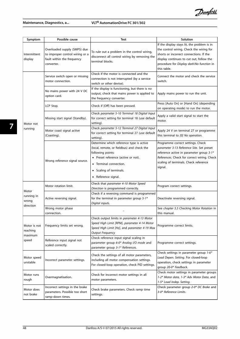
Symptom Possible cause Test Solution
Intermittentdisplay
Overloaded supply (SMPS) dueto improper control wiring or afault within the frequencyconverter.
To rule out a problem in the control wiring,disconnect all control wiring by removing theterminal blocks.
If the display stays lit, the problem is inthe control wiring. Check the wiring forshorts or incorrect connections. If thedisplay continues to cut out, follow theprocedure for Display dark\No function inthis table.
Motor notrunning
Service switch open or missingmotor connection.
Check if the motor is connected and theconnection is not interrupted (by a serviceswitch or other devise).
Connect the motor and check the serviceswitch.
No mains power with 24 V DCoption card.
If the display is functioning, but there is nooutput, check that mains power is applied tothe frequency converter.
Apply mains power to run the unit.
LCP Stop. Check if [Off] has been pressed.Press [Auto On] or [Hand On] (dependingon operating mode) to run the motor.
Missing start signal (Standby).Check parameter 5-10 Terminal 18 Digital Inputfor correct setting for terminal 18 (use defaultsetting).
Apply a valid start signal to start themotor.
Motor coast signal active(Coasting).
Check parameter 5-12 Terminal 27 Digital Inputfor correct setting for terminal 27 (use defaultsetting).
Apply 24 V on terminal 27 or programmethis terminal to [0] No operation.
Wrong reference signal source.
Determine which reference type is active(local, remote, or fieldbus) and check thefollowing points:
• Preset reference (active or not).
• Terminal connection.
• Scaling of terminals.
• Reference signal.
Programme correct settings. Checkparameter 3-13 Reference Site. Set presetreference active in parameter group 3-1*References. Check for correct wiring. Checkscaling of terminals. Check referencesignal.
Motorrunning inwrongdirection
Motor rotation limit.Check that parameter 4-10 Motor SpeedDirection is programmed correctly.
Program correct settings.
Active reversing signal.Check if a reversing command is programmedfor the terminal in parameter group 5-1*Digital inputs.
Deactivate reversing signal.
Wrong motor phaseconnection.
–See chapter 5.5 Checking Motor Rotation inthis manual.
Motor is notreachingmaximumspeed
Frequency limits set wrong.
Check output limits in parameter 4-13 MotorSpeed High Limit [RPM], parameter 4-14 MotorSpeed High Limit [Hz], and parameter 4-19 MaxOutput Frequency
Programme correct limits.
Reference input signal notscaled correctly.
Check reference input signal scaling inparameter group 6-0* Analog I/O mode andparameter group 3-1* References.
Programme correct settings.
Motor speedunstable
Incorrect parameter settings.Check the settings of all motor parameters,including all motor compensation settings.For closed-loop operation, check PID settings.
Check settings in parameter group 1-6*Load Depen. Setting. For closed-loopoperation, check settings in parametergroup 20-0* Feedback.
Motor runsrough
Overmagnetisation.Check for incorrect motor settings in allmotor parameters.
Check motor settings in parameter groups1-2* Motor data, 1-3* Adv Motor Data, and1-5* Load Indep. Setting.
Motor doesnot brake
Incorrect settings in the brakeparameters. Possible too shortramp-down times.
Check brake parameters. Check ramp timesettings.
Check parameter group 2-0* DC Brake and3-0* Reference Limits.
Maintenance, Diagnostics, a... VLT® AutomationDrive FC 301/302
48 Danfoss A/S © 07/2015 All rights reserved. MG33AQ02
77
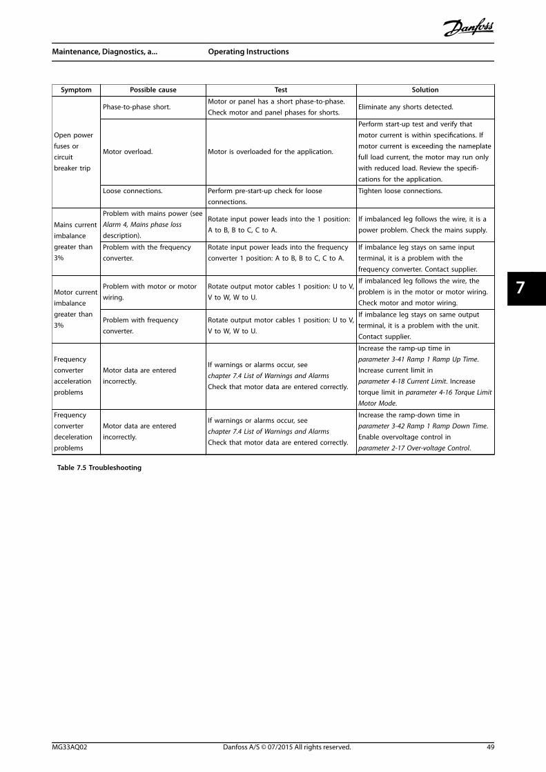
Symptom Possible cause Test Solution
Open powerfuses orcircuitbreaker trip
Phase-to-phase short.Motor or panel has a short phase-to-phase.Check motor and panel phases for shorts.
Eliminate any shorts detected.
Motor overload. Motor is overloaded for the application.
Perform start-up test and verify thatmotor current is within specifications. Ifmotor current is exceeding the nameplatefull load current, the motor may run onlywith reduced load. Review the specifi-cations for the application.
Loose connections. Perform pre-start-up check for looseconnections.
Tighten loose connections.
Mains currentimbalancegreater than3%
Problem with mains power (seeAlarm 4, Mains phase lossdescription).
Rotate input power leads into the 1 position:A to B, B to C, C to A.
If imbalanced leg follows the wire, it is apower problem. Check the mains supply.
Problem with the frequencyconverter.
Rotate input power leads into the frequencyconverter 1 position: A to B, B to C, C to A.
If imbalance leg stays on same inputterminal, it is a problem with thefrequency converter. Contact supplier.
Motor currentimbalancegreater than3%
Problem with motor or motorwiring.
Rotate output motor cables 1 position: U to V,V to W, W to U.
If imbalanced leg follows the wire, theproblem is in the motor or motor wiring.Check motor and motor wiring.
Problem with frequencyconverter.
Rotate output motor cables 1 position: U to V,V to W, W to U.
If imbalance leg stays on same outputterminal, it is a problem with the unit.Contact supplier.
Frequencyconverteraccelerationproblems
Motor data are enteredincorrectly.
If warnings or alarms occur, seechapter 7.4 List of Warnings and AlarmsCheck that motor data are entered correctly.
Increase the ramp-up time inparameter 3-41 Ramp 1 Ramp Up Time.Increase current limit inparameter 4-18 Current Limit. Increasetorque limit in parameter 4-16 Torque LimitMotor Mode.
Frequencyconverterdecelerationproblems
Motor data are enteredincorrectly.
If warnings or alarms occur, seechapter 7.4 List of Warnings and AlarmsCheck that motor data are entered correctly.
Increase the ramp-down time inparameter 3-42 Ramp 1 Ramp Down Time.Enable overvoltage control inparameter 2-17 Over-voltage Control.
Table 7.5 Troubleshooting
Maintenance, Diagnostics, a... Operating Instructions
MG33AQ02 Danfoss A/S © 07/2015 All rights reserved. 49
7 7
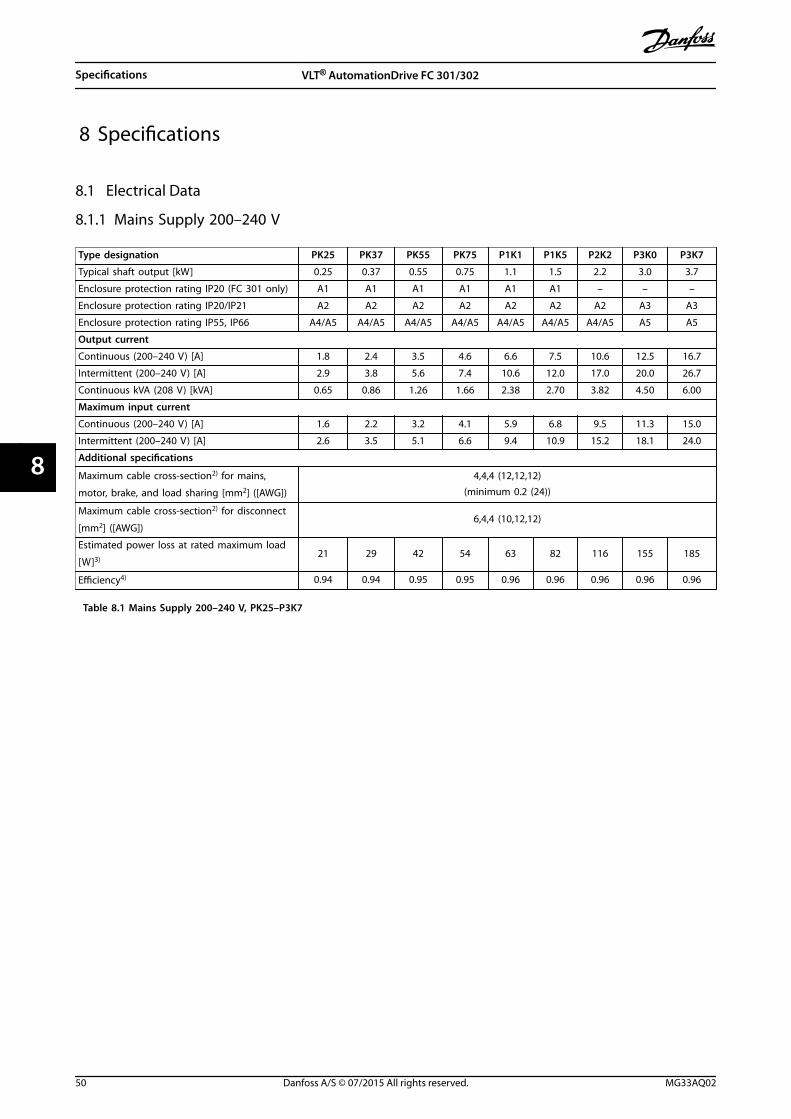
8 Specifications
8.1 Electrical Data
8.1.1 Mains Supply 200–240 V
Type designation PK25 PK37 PK55 PK75 P1K1 P1K5 P2K2 P3K0 P3K7
Typical shaft output [kW] 0.25 0.37 0.55 0.75 1.1 1.5 2.2 3.0 3.7
Enclosure protection rating IP20 (FC 301 only) A1 A1 A1 A1 A1 A1 – – –
Enclosure protection rating IP20/IP21 A2 A2 A2 A2 A2 A2 A2 A3 A3
Enclosure protection rating IP55, IP66 A4/A5 A4/A5 A4/A5 A4/A5 A4/A5 A4/A5 A4/A5 A5 A5
Output current
Continuous (200–240 V) [A] 1.8 2.4 3.5 4.6 6.6 7.5 10.6 12.5 16.7
Intermittent (200–240 V) [A] 2.9 3.8 5.6 7.4 10.6 12.0 17.0 20.0 26.7
Continuous kVA (208 V) [kVA] 0.65 0.86 1.26 1.66 2.38 2.70 3.82 4.50 6.00
Maximum input current
Continuous (200–240 V) [A] 1.6 2.2 3.2 4.1 5.9 6.8 9.5 11.3 15.0
Intermittent (200–240 V) [A] 2.6 3.5 5.1 6.6 9.4 10.9 15.2 18.1 24.0
Additional specifications
Maximum cable cross-section2) for mains,
motor, brake, and load sharing [mm2] ([AWG])
4,4,4 (12,12,12)(minimum 0.2 (24))
Maximum cable cross-section2) for disconnect
[mm2] ([AWG])6,4,4 (10,12,12)
Estimated power loss at rated maximum load
[W]3)21 29 42 54 63 82 116 155 185
Efficiency4) 0.94 0.94 0.95 0.95 0.96 0.96 0.96 0.96 0.96
Table 8.1 Mains Supply 200–240 V, PK25–P3K7
Specifications VLT® AutomationDrive FC 301/302
50 Danfoss A/S © 07/2015 All rights reserved. MG33AQ02
88
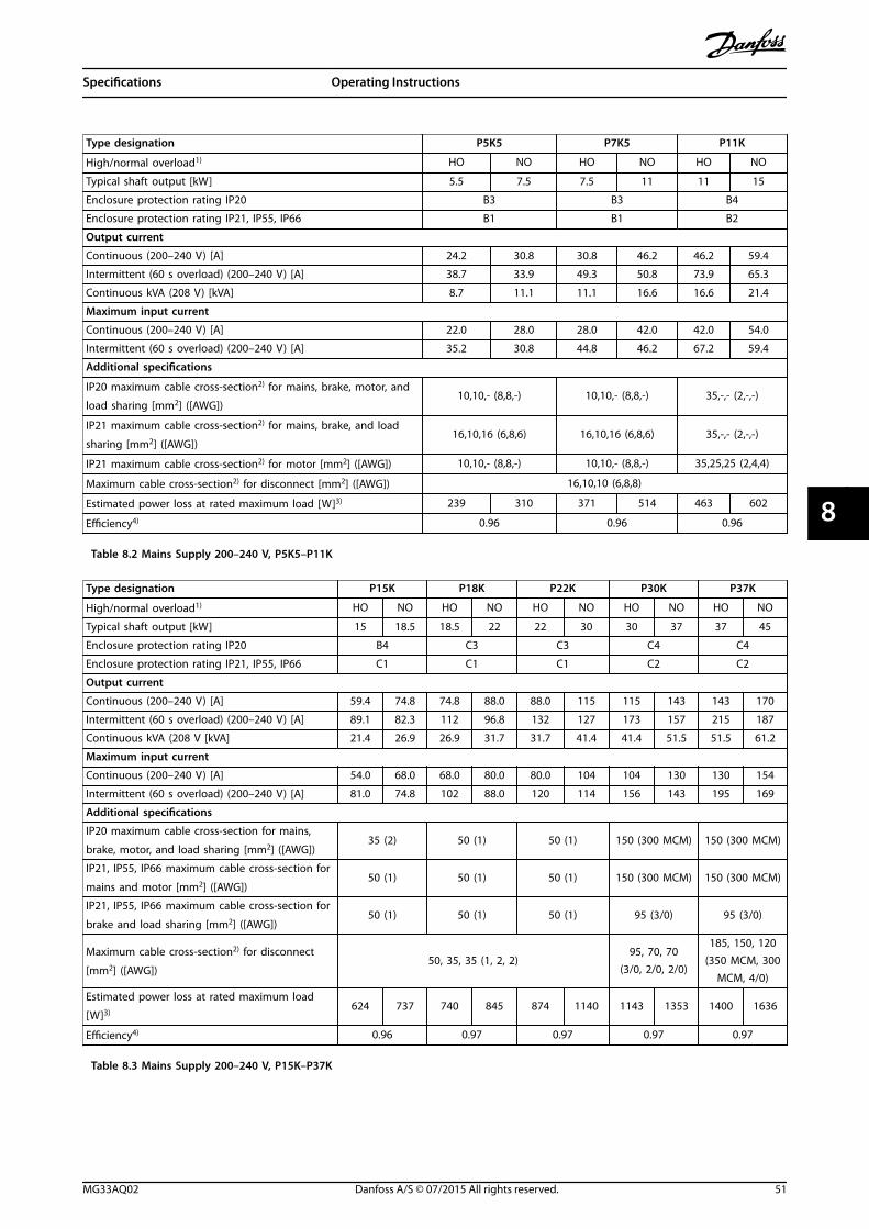
Type designation P5K5 P7K5 P11K
High/normal overload1) HO NO HO NO HO NO
Typical shaft output [kW] 5.5 7.5 7.5 11 11 15
Enclosure protection rating IP20 B3 B3 B4
Enclosure protection rating IP21, IP55, IP66 B1 B1 B2
Output current
Continuous (200–240 V) [A] 24.2 30.8 30.8 46.2 46.2 59.4
Intermittent (60 s overload) (200–240 V) [A] 38.7 33.9 49.3 50.8 73.9 65.3
Continuous kVA (208 V) [kVA] 8.7 11.1 11.1 16.6 16.6 21.4
Maximum input current
Continuous (200–240 V) [A] 22.0 28.0 28.0 42.0 42.0 54.0
Intermittent (60 s overload) (200–240 V) [A] 35.2 30.8 44.8 46.2 67.2 59.4
Additional specifications
IP20 maximum cable cross-section2) for mains, brake, motor, and
load sharing [mm2] ([AWG])10,10,- (8,8,-) 10,10,- (8,8,-) 35,-,- (2,-,-)
IP21 maximum cable cross-section2) for mains, brake, and load
sharing [mm2] ([AWG])16,10,16 (6,8,6) 16,10,16 (6,8,6) 35,-,- (2,-,-)
IP21 maximum cable cross-section2) for motor [mm2] ([AWG]) 10,10,- (8,8,-) 10,10,- (8,8,-) 35,25,25 (2,4,4)
Maximum cable cross-section2) for disconnect [mm2] ([AWG]) 16,10,10 (6,8,8)
Estimated power loss at rated maximum load [W]3) 239 310 371 514 463 602
Efficiency4) 0.96 0.96 0.96
Table 8.2 Mains Supply 200–240 V, P5K5–P11K
Type designation P15K P18K P22K P30K P37K
High/normal overload1) HO NO HO NO HO NO HO NO HO NO
Typical shaft output [kW] 15 18.5 18.5 22 22 30 30 37 37 45
Enclosure protection rating IP20 B4 C3 C3 C4 C4
Enclosure protection rating IP21, IP55, IP66 C1 C1 C1 C2 C2
Output current
Continuous (200–240 V) [A] 59.4 74.8 74.8 88.0 88.0 115 115 143 143 170
Intermittent (60 s overload) (200–240 V) [A] 89.1 82.3 112 96.8 132 127 173 157 215 187
Continuous kVA (208 V [kVA] 21.4 26.9 26.9 31.7 31.7 41.4 41.4 51.5 51.5 61.2
Maximum input current
Continuous (200–240 V) [A] 54.0 68.0 68.0 80.0 80.0 104 104 130 130 154
Intermittent (60 s overload) (200–240 V) [A] 81.0 74.8 102 88.0 120 114 156 143 195 169
Additional specifications
IP20 maximum cable cross-section for mains,
brake, motor, and load sharing [mm2] ([AWG])35 (2) 50 (1) 50 (1) 150 (300 MCM) 150 (300 MCM)
IP21, IP55, IP66 maximum cable cross-section for
mains and motor [mm2] ([AWG])50 (1) 50 (1) 50 (1) 150 (300 MCM) 150 (300 MCM)
IP21, IP55, IP66 maximum cable cross-section for
brake and load sharing [mm2] ([AWG])50 (1) 50 (1) 50 (1) 95 (3/0) 95 (3/0)
Maximum cable cross-section2) for disconnect
[mm2] ([AWG])50, 35, 35 (1, 2, 2)
95, 70, 70(3/0, 2/0, 2/0)
185, 150, 120(350 MCM, 300
MCM, 4/0)
Estimated power loss at rated maximum load
[W]3)624 737 740 845 874 1140 1143 1353 1400 1636
Efficiency4) 0.96 0.97 0.97 0.97 0.97
Table 8.3 Mains Supply 200–240 V, P15K–P37K
Specifications Operating Instructions
MG33AQ02 Danfoss A/S © 07/2015 All rights reserved. 51
8 8
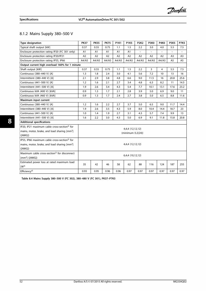
8.1.2 Mains Supply 380–500 V
Type designation PK37 PK55 PK75 P1K1 P1K5 P2K2 P3K0 P4K0 P5K5 P7K5
Typical shaft output [kW] 0.37 0.55 0.75 1.1 1.5 2.2 3.0 4.0 5.5 7.5
Enclosure protection rating IP20 (FC 301 only) A1 A1 A1 A1 A1 – – – – –
Enclosure protection rating IP20/IP21 A2 A2 A2 A2 A2 A2 A2 A2 A3 A3
Enclosure protection rating IP55, IP66 A4/A5 A4/A5 A4/A5 A4/A5 A4/A5 A4/A5 A4/A5 A4/A5 A5 A5
Output current high overload 160% for 1 minute
Shaft output [kW] 0.37 0.55 0.75 1.1 1.5 2.2 3 4 5.5 7.5
Continuous (380–440 V) [A] 1.3 1.8 2.4 3.0 4.1 5.6 7.2 10 13 16
Intermittent (380–440 V) [A] 2.1 2.9 3.8 4.8 6.6 9.0 11.5 16 20.8 25.6
Continuous (441–500 V) [A] 1.2 1.6 2.1 2.7 3.4 4.8 6.3 8.2 11 14.5
Intermittent (441–500 V) [A] 1.9 2.6 3.4 4.3 5.4 7.7 10.1 13.1 17.6 23.2
Continuous kVA (400 V) [kVA] 0.9 1.3 1.7 2.1 2.8 3.9 5.0 6.9 9.0 11
Continuous kVA (460 V) [kVA] 0.9 1.3 1.7 2.4 2.7 3.8 5.0 6.5 8.8 11.6
Maximum input current
Continuous (380–440 V) [A] 1.2 1.6 2.2 2.7 3.7 5.0 6.5 9.0 11.7 14.4
Intermittent (380–440 V) [A] 1.9 2.6 3.5 4.3 5.9 8.0 10.4 14.4 18.7 23
Continuous (441–500 V) [A] 1.0 1.4 1.9 2.7 3.1 4.3 5.7 7.4 9.9 13
Intermittent (441–500 V) [A] 1.6 2.2 3.0 4.3 5.0 6.9 9.1 11.8 15.8 20.8
Additional specifications
IP20, IP21 maximum cable cross-section2) for
mains, motor, brake, and load sharing [mm2]([AWG])
4,4,4 (12,12,12)(minimum 0.2(24))
IP55, IP66 maximum cable cross-section2) for
mains, motor, brake, and load sharing [mm2]([AWG])
4,4,4 (12,12,12)
Maximum cable cross-section2) for disconnect
[mm2] ([AWG])6,4,4 (10,12,12)
Estimated power loss at rated maximum load
[W3)35 42 46 58 62 88 116 124 187 255
Efficiency4) 0.93 0.95 0.96 0.96 0.97 0.97 0.97 0.97 0.97 0.97
Table 8.4 Mains Supply 380–500 V (FC 302), 380–480 V (FC 301), PK37–P7K5
Specifications VLT® AutomationDrive FC 301/302
52 Danfoss A/S © 07/2015 All rights reserved. MG33AQ02
88
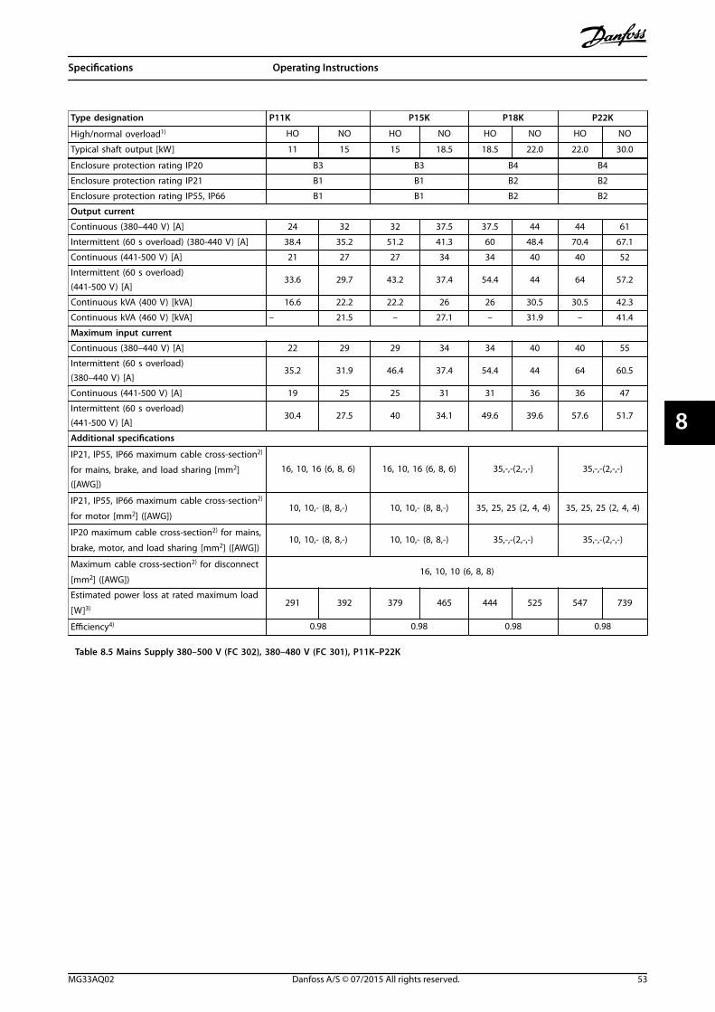
Type designation P11K P15K P18K P22K
High/normal overload1) HO NO HO NO HO NO HO NO
Typical shaft output [kW] 11 15 15 18.5 18.5 22.0 22.0 30.0
Enclosure protection rating IP20 B3 B3 B4 B4
Enclosure protection rating IP21 B1 B1 B2 B2
Enclosure protection rating IP55, IP66 B1 B1 B2 B2
Output current
Continuous (380–440 V) [A] 24 32 32 37.5 37.5 44 44 61
Intermittent (60 s overload) (380-440 V) [A] 38.4 35.2 51.2 41.3 60 48.4 70.4 67.1
Continuous (441-500 V) [A] 21 27 27 34 34 40 40 52
Intermittent (60 s overload)(441-500 V) [A]
33.6 29.7 43.2 37.4 54.4 44 64 57.2
Continuous kVA (400 V) [kVA] 16.6 22.2 22.2 26 26 30.5 30.5 42.3
Continuous kVA (460 V) [kVA] – 21.5 – 27.1 – 31.9 – 41.4
Maximum input current
Continuous (380–440 V) [A] 22 29 29 34 34 40 40 55
Intermittent (60 s overload)(380–440 V) [A]
35.2 31.9 46.4 37.4 54.4 44 64 60.5
Continuous (441-500 V) [A] 19 25 25 31 31 36 36 47
Intermittent (60 s overload)(441-500 V) [A]
30.4 27.5 40 34.1 49.6 39.6 57.6 51.7
Additional specifications
IP21, IP55, IP66 maximum cable cross-section2)
for mains, brake, and load sharing [mm2]([AWG])
16, 10, 16 (6, 8, 6) 16, 10, 16 (6, 8, 6) 35,-,-(2,-,-) 35,-,-(2,-,-)
IP21, IP55, IP66 maximum cable cross-section2)
for motor [mm2] ([AWG])10, 10,- (8, 8,-) 10, 10,- (8, 8,-) 35, 25, 25 (2, 4, 4) 35, 25, 25 (2, 4, 4)
IP20 maximum cable cross-section2) for mains,
brake, motor, and load sharing [mm2] ([AWG])10, 10,- (8, 8,-) 10, 10,- (8, 8,-) 35,-,-(2,-,-) 35,-,-(2,-,-)
Maximum cable cross-section2) for disconnect
[mm2] ([AWG])16, 10, 10 (6, 8, 8)
Estimated power loss at rated maximum load
[W]3)291 392 379 465 444 525 547 739
Efficiency4) 0.98 0.98 0.98 0.98
Table 8.5 Mains Supply 380–500 V (FC 302), 380–480 V (FC 301), P11K–P22K
Specifications Operating Instructions
MG33AQ02 Danfoss A/S © 07/2015 All rights reserved. 53
8 8
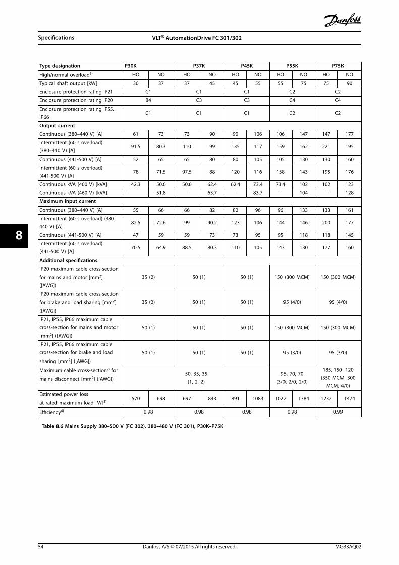
Type designation P30K P37K P45K P55K P75K
High/normal overload1) HO NO HO NO HO NO HO NO HO NO
Typical shaft output [kW] 30 37 37 45 45 55 55 75 75 90
Enclosure protection rating IP21 C1 C1 C1 C2 C2
Enclosure protection rating IP20 B4 C3 C3 C4 C4
Enclosure protection rating IP55,IP66
C1 C1 C1 C2 C2
Output current
Continuous (380–440 V) [A] 61 73 73 90 90 106 106 147 147 177
Intermittent (60 s overload)(380–440 V) [A]
91.5 80.3 110 99 135 117 159 162 221 195
Continuous (441-500 V) [A] 52 65 65 80 80 105 105 130 130 160
Intermittent (60 s overload)(441-500 V) [A]
78 71.5 97.5 88 120 116 158 143 195 176
Continuous kVA (400 V) [kVA] 42.3 50.6 50.6 62.4 62.4 73.4 73.4 102 102 123
Continuous kVA (460 V) [kVA] – 51.8 – 63.7 – 83.7 – 104 – 128
Maximum input current
Continuous (380–440 V) [A] 55 66 66 82 82 96 96 133 133 161
Intermittent (60 s overload) (380–440 V) [A]
82.5 72.6 99 90.2 123 106 144 146 200 177
Continuous (441-500 V) [A] 47 59 59 73 73 95 95 118 118 145
Intermittent (60 s overload)(441-500 V) [A]
70.5 64.9 88.5 80.3 110 105 143 130 177 160
Additional specifications
IP20 maximum cable cross-section
for mains and motor [mm2]([AWG])
35 (2) 50 (1) 50 (1) 150 (300 MCM) 150 (300 MCM)
IP20 maximum cable cross-section
for brake and load sharing [mm2]([AWG])
35 (2) 50 (1) 50 (1) 95 (4/0) 95 (4/0)
IP21, IP55, IP66 maximum cablecross-section for mains and motor
[mm2] ([AWG])
50 (1) 50 (1) 50 (1) 150 (300 MCM) 150 (300 MCM)
IP21, IP55, IP66 maximum cablecross-section for brake and load
sharing [mm2] ([AWG])
50 (1) 50 (1) 50 (1) 95 (3/0) 95 (3/0)
Maximum cable cross-section2) for
mains disconnect [mm2] ([AWG])50, 35, 35
(1, 2, 2)95, 70, 70
(3/0, 2/0, 2/0)
185, 150, 120(350 MCM, 300
MCM, 4/0)
Estimated power loss
at rated maximum load [W]3)570 698 697 843 891 1083 1022 1384 1232 1474
Efficiency4) 0.98 0.98 0.98 0.98 0.99
Table 8.6 Mains Supply 380–500 V (FC 302), 380–480 V (FC 301), P30K–P75K
Specifications VLT® AutomationDrive FC 301/302
54 Danfoss A/S © 07/2015 All rights reserved. MG33AQ02
88
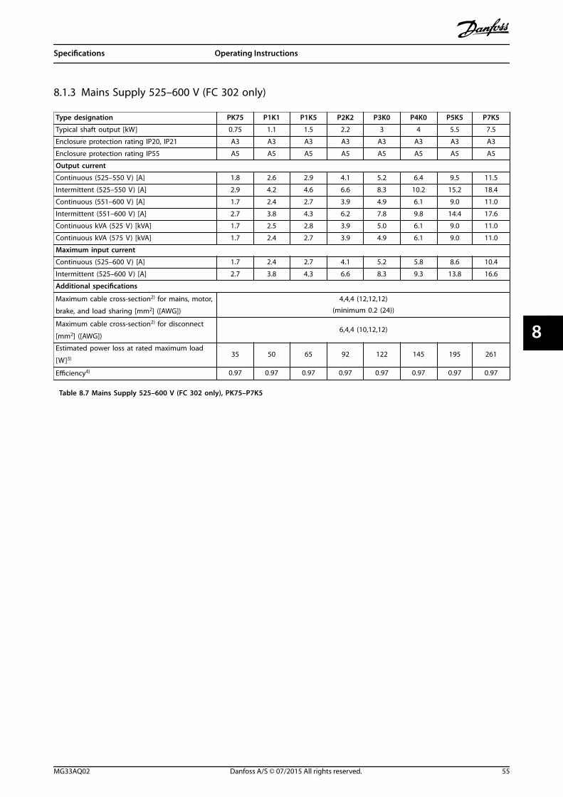
8.1.3 Mains Supply 525–600 V (FC 302 only)
Type designation PK75 P1K1 P1K5 P2K2 P3K0 P4K0 P5K5 P7K5
Typical shaft output [kW] 0.75 1.1 1.5 2.2 3 4 5.5 7.5
Enclosure protection rating IP20, IP21 A3 A3 A3 A3 A3 A3 A3 A3
Enclosure protection rating IP55 A5 A5 A5 A5 A5 A5 A5 A5
Output current
Continuous (525–550 V) [A] 1.8 2.6 2.9 4.1 5.2 6.4 9.5 11.5
Intermittent (525–550 V) [A] 2.9 4.2 4.6 6.6 8.3 10.2 15.2 18.4
Continuous (551–600 V) [A] 1.7 2.4 2.7 3.9 4.9 6.1 9.0 11.0
Intermittent (551–600 V) [A] 2.7 3.8 4.3 6.2 7.8 9.8 14.4 17.6
Continuous kVA (525 V) [kVA] 1.7 2.5 2.8 3.9 5.0 6.1 9.0 11.0
Continuous kVA (575 V) [kVA] 1.7 2.4 2.7 3.9 4.9 6.1 9.0 11.0
Maximum input current
Continuous (525–600 V) [A] 1.7 2.4 2.7 4.1 5.2 5.8 8.6 10.4
Intermittent (525–600 V) [A] 2.7 3.8 4.3 6.6 8.3 9.3 13.8 16.6
Additional specifications
Maximum cable cross-section2) for mains, motor,
brake, and load sharing [mm2] ([AWG])
4,4,4 (12,12,12)(minimum 0.2 (24))
Maximum cable cross-section2) for disconnect
[mm2] ([AWG])6,4,4 (10,12,12)
Estimated power loss at rated maximum load
[W]3)35 50 65 92 122 145 195 261
Efficiency4) 0.97 0.97 0.97 0.97 0.97 0.97 0.97 0.97
Table 8.7 Mains Supply 525–600 V (FC 302 only), PK75–P7K5
Specifications Operating Instructions
MG33AQ02 Danfoss A/S © 07/2015 All rights reserved. 55
8 8
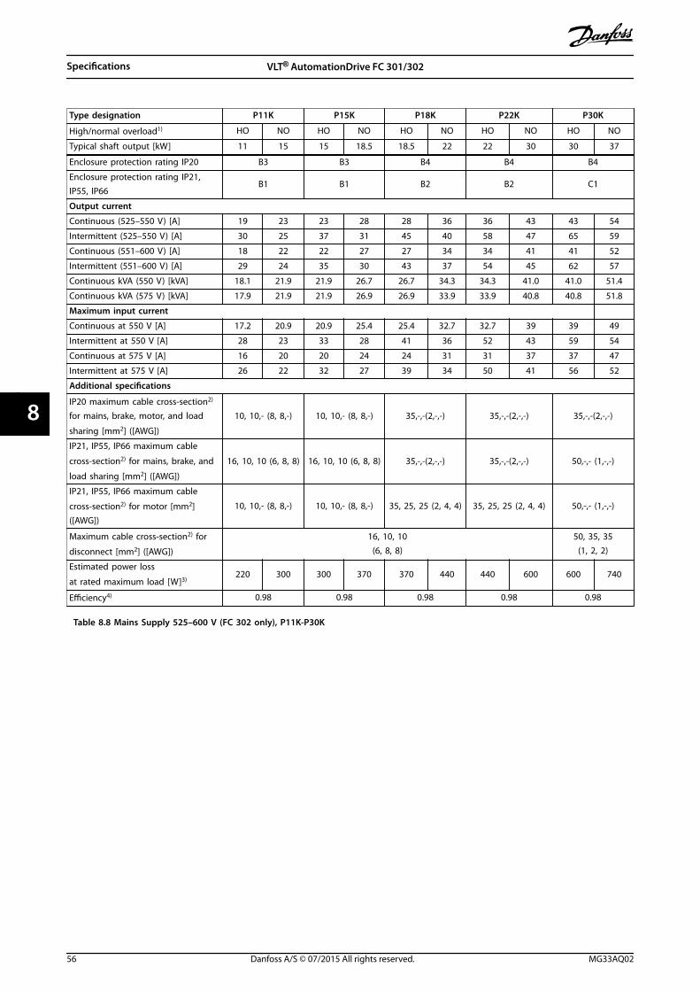
Type designation P11K P15K P18K P22K P30K
High/normal overload1) HO NO HO NO HO NO HO NO HO NO
Typical shaft output [kW] 11 15 15 18.5 18.5 22 22 30 30 37
Enclosure protection rating IP20 B3 B3 B4 B4 B4
Enclosure protection rating IP21,IP55, IP66
B1 B1 B2 B2 C1
Output current
Continuous (525–550 V) [A] 19 23 23 28 28 36 36 43 43 54
Intermittent (525–550 V) [A] 30 25 37 31 45 40 58 47 65 59
Continuous (551–600 V) [A] 18 22 22 27 27 34 34 41 41 52
Intermittent (551–600 V) [A] 29 24 35 30 43 37 54 45 62 57
Continuous kVA (550 V) [kVA] 18.1 21.9 21.9 26.7 26.7 34.3 34.3 41.0 41.0 51.4
Continuous kVA (575 V) [kVA] 17.9 21.9 21.9 26.9 26.9 33.9 33.9 40.8 40.8 51.8
Maximum input current
Continuous at 550 V [A] 17.2 20.9 20.9 25.4 25.4 32.7 32.7 39 39 49
Intermittent at 550 V [A] 28 23 33 28 41 36 52 43 59 54
Continuous at 575 V [A] 16 20 20 24 24 31 31 37 37 47
Intermittent at 575 V [A] 26 22 32 27 39 34 50 41 56 52
Additional specifications
IP20 maximum cable cross-section2)
for mains, brake, motor, and load
sharing [mm2] ([AWG])
10, 10,- (8, 8,-) 10, 10,- (8, 8,-) 35,-,-(2,-,-) 35,-,-(2,-,-) 35,-,-(2,-,-)
IP21, IP55, IP66 maximum cable
cross-section2) for mains, brake, and
load sharing [mm2] ([AWG])
16, 10, 10 (6, 8, 8) 16, 10, 10 (6, 8, 8) 35,-,-(2,-,-) 35,-,-(2,-,-) 50,-,- (1,-,-)
IP21, IP55, IP66 maximum cable
cross-section2) for motor [mm2]([AWG])
10, 10,- (8, 8,-) 10, 10,- (8, 8,-) 35, 25, 25 (2, 4, 4) 35, 25, 25 (2, 4, 4) 50,-,- (1,-,-)
Maximum cable cross-section2) for
disconnect [mm2] ([AWG])
16, 10, 10(6, 8, 8)
50, 35, 35(1, 2, 2)
Estimated power loss
at rated maximum load [W]3)220 300 300 370 370 440 440 600 600 740
Efficiency4) 0.98 0.98 0.98 0.98 0.98
Table 8.8 Mains Supply 525–600 V (FC 302 only), P11K-P30K
Specifications VLT® AutomationDrive FC 301/302
56 Danfoss A/S © 07/2015 All rights reserved. MG33AQ02
88
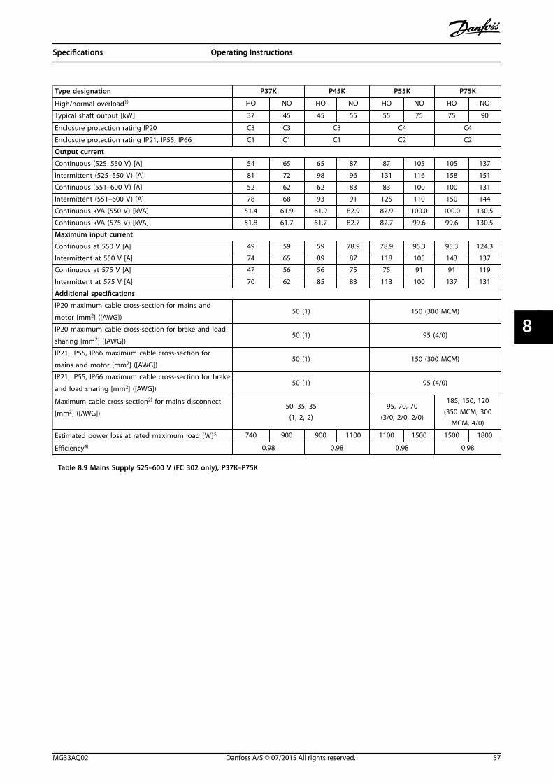
Type designation P37K P45K P55K P75K
High/normal overload1) HO NO HO NO HO NO HO NO
Typical shaft output [kW] 37 45 45 55 55 75 75 90
Enclosure protection rating IP20 C3 C3 C3 C4 C4
Enclosure protection rating IP21, IP55, IP66 C1 C1 C1 C2 C2
Output current
Continuous (525–550 V) [A] 54 65 65 87 87 105 105 137
Intermittent (525–550 V) [A] 81 72 98 96 131 116 158 151
Continuous (551–600 V) [A] 52 62 62 83 83 100 100 131
Intermittent (551–600 V) [A] 78 68 93 91 125 110 150 144
Continuous kVA (550 V) [kVA] 51.4 61.9 61.9 82.9 82.9 100.0 100.0 130.5
Continuous kVA (575 V) [kVA] 51.8 61.7 61.7 82.7 82.7 99.6 99.6 130.5
Maximum input current
Continuous at 550 V [A] 49 59 59 78.9 78.9 95.3 95.3 124.3
Intermittent at 550 V [A] 74 65 89 87 118 105 143 137
Continuous at 575 V [A] 47 56 56 75 75 91 91 119
Intermittent at 575 V [A] 70 62 85 83 113 100 137 131
Additional specifications
IP20 maximum cable cross-section for mains and
motor [mm2] ([AWG])50 (1) 150 (300 MCM)
IP20 maximum cable cross-section for brake and load
sharing [mm2] ([AWG])50 (1) 95 (4/0)
IP21, IP55, IP66 maximum cable cross-section for
mains and motor [mm2] ([AWG])50 (1) 150 (300 MCM)
IP21, IP55, IP66 maximum cable cross-section for brake
and load sharing [mm2] ([AWG])50 (1) 95 (4/0)
Maximum cable cross-section2) for mains disconnect
[mm2] ([AWG])50, 35, 35
(1, 2, 2)95, 70, 70
(3/0, 2/0, 2/0)
185, 150, 120(350 MCM, 300
MCM, 4/0)
Estimated power loss at rated maximum load [W]3) 740 900 900 1100 1100 1500 1500 1800
Efficiency4) 0.98 0.98 0.98 0.98
Table 8.9 Mains Supply 525–600 V (FC 302 only), P37K–P75K
Specifications Operating Instructions
MG33AQ02 Danfoss A/S © 07/2015 All rights reserved. 57
8 8
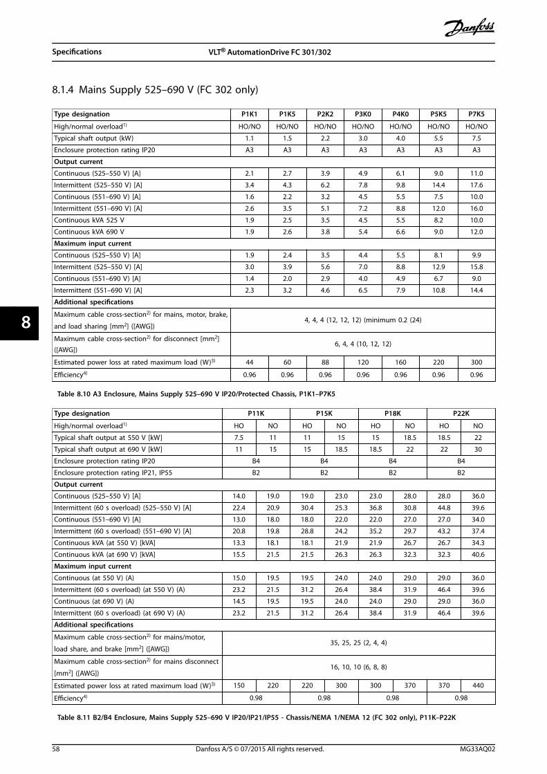
8.1.4 Mains Supply 525–690 V (FC 302 only)
Type designation P1K1 P1K5 P2K2 P3K0 P4K0 P5K5 P7K5
High/normal overload1) HO/NO HO/NO HO/NO HO/NO HO/NO HO/NO HO/NO
Typical shaft output (kW) 1.1 1.5 2.2 3.0 4.0 5.5 7.5
Enclosure protection rating IP20 A3 A3 A3 A3 A3 A3 A3
Output current
Continuous (525–550 V) [A] 2.1 2.7 3.9 4.9 6.1 9.0 11.0
Intermittent (525–550 V) [A] 3.4 4.3 6.2 7.8 9.8 14.4 17.6
Continuous (551–690 V) [A] 1.6 2.2 3.2 4.5 5.5 7.5 10.0
Intermittent (551–690 V) [A] 2.6 3.5 5.1 7.2 8.8 12.0 16.0
Continuous kVA 525 V 1.9 2.5 3.5 4.5 5.5 8.2 10.0
Continuous kVA 690 V 1.9 2.6 3.8 5.4 6.6 9.0 12.0
Maximum input current
Continuous (525–550 V) [A] 1.9 2.4 3.5 4.4 5.5 8.1 9.9
Intermittent (525–550 V) [A] 3.0 3.9 5.6 7.0 8.8 12.9 15.8
Continuous (551–690 V) [A] 1.4 2.0 2.9 4.0 4.9 6.7 9.0
Intermittent (551–690 V) [A] 2.3 3.2 4.6 6.5 7.9 10.8 14.4
Additional specifications
Maximum cable cross-section2) for mains, motor, brake,
and load sharing [mm2] ([AWG])4, 4, 4 (12, 12, 12) (minimum 0.2 (24)
Maximum cable cross-section2) for disconnect [mm2]([AWG])
6, 4, 4 (10, 12, 12)
Estimated power loss at rated maximum load (W)3) 44 60 88 120 160 220 300
Efficiency4) 0.96 0.96 0.96 0.96 0.96 0.96 0.96
Table 8.10 A3 Enclosure, Mains Supply 525–690 V IP20/Protected Chassis, P1K1–P7K5
Type designation P11K P15K P18K P22K
High/normal overload1) HO NO HO NO HO NO HO NO
Typical shaft output at 550 V [kW] 7.5 11 11 15 15 18.5 18.5 22
Typical shaft output at 690 V [kW] 11 15 15 18.5 18.5 22 22 30
Enclosure protection rating IP20 B4 B4 B4 B4
Enclosure protection rating IP21, IP55 B2 B2 B2 B2
Output current
Continuous (525–550 V) [A] 14.0 19.0 19.0 23.0 23.0 28.0 28.0 36.0
Intermittent (60 s overload) (525–550 V) [A] 22.4 20.9 30.4 25.3 36.8 30.8 44.8 39.6
Continuous (551–690 V) [A] 13.0 18.0 18.0 22.0 22.0 27.0 27.0 34.0
Intermittent (60 s overload) (551–690 V) [A] 20.8 19.8 28.8 24.2 35.2 29.7 43.2 37.4
Continuous kVA (at 550 V) [kVA] 13.3 18.1 18.1 21.9 21.9 26.7 26.7 34.3
Continuous kVA (at 690 V) [kVA] 15.5 21.5 21.5 26.3 26.3 32.3 32.3 40.6
Maximum input current
Continuous (at 550 V) (A) 15.0 19.5 19.5 24.0 24.0 29.0 29.0 36.0
Intermittent (60 s overload) (at 550 V) (A) 23.2 21.5 31.2 26.4 38.4 31.9 46.4 39.6
Continuous (at 690 V) (A) 14.5 19.5 19.5 24.0 24.0 29.0 29.0 36.0
Intermittent (60 s overload) (at 690 V) (A) 23.2 21.5 31.2 26.4 38.4 31.9 46.4 39.6
Additional specifications
Maximum cable cross-section2) for mains/motor,
load share, and brake [mm2] ([AWG])35, 25, 25 (2, 4, 4)
Maximum cable cross-section2) for mains disconnect
[mm2] ([AWG])16, 10, 10 (6, 8, 8)
Estimated power loss at rated maximum load (W)3) 150 220 220 300 300 370 370 440
Efficiency4) 0.98 0.98 0.98 0.98
Table 8.11 B2/B4 Enclosure, Mains Supply 525–690 V IP20/IP21/IP55 - Chassis/NEMA 1/NEMA 12 (FC 302 only), P11K–P22K
Specifications VLT® AutomationDrive FC 301/302
58 Danfoss A/S © 07/2015 All rights reserved. MG33AQ02
88
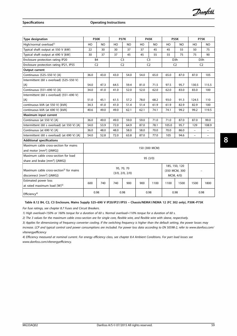
Type designation P30K P37K P45K P55K P75K
High/normal overload1) HO NO HO NO HO NO HO NO HO NO
Typical shaft output at 550 V (kW) 22 30 30 37 37 45 45 55 50 75
Typical shaft output at 690 V [kW] 30 37 37 45 45 55 55 75 75 90
Enclosure protection rating IP20 B4 C3 C3 D3h D3h
Enclosure protection rating IP21, IP55 C2 C2 C2 C2 C2
Output current
Continuous (525–550 V) [A] 36.0 43.0 43.0 54.0 54.0 65.0 65.0 87.0 87.0 105
Intermittent (60 s overload) (525–550 V)[A] 54.0 47.3 64.5 59.4 81.0 71.5 97.5 95.7 130.5 115.5
Continuous (551–690 V) [A] 34.0 41.0 41.0 52.0 52.0 62.0 62.0 83.0 83.0 100
Intermittent (60 s overload) (551–690 V)[A] 51.0 45.1 61.5 57.2 78.0 68.2 93.0 91.3 124.5 110
continuous kVA (at 550 V) [kVA] 34.3 41.0 41.0 51.4 51.4 61.9 61.9 82.9 82.9 100
continuous kVA (at 690 V) [kVA] 40.6 49.0 49.0 62.1 62.1 74.1 74.1 99.2 99.2 119.5
Maximum input current
Continuous (at 550 V) [A] 36.0 49.0 49.0 59.0 59.0 71.0 71.0 87.0 87.0 99.0
Intermittent (60 s overload) (at 550 V) [A] 54.0 53.9 72.0 64.9 87.0 78.1 105.0 95.7 129 108.9
Continuous (at 690 V) [A] 36.0 48.0 48.0 58.0 58.0 70.0 70.0 86.0 – –
Intermittent (60 s overload) (at 690 V) [A] 54.0 52.8 72.0 63.8 87.0 77.0 105 94.6 – –
Additional specifications
Maximum cable cross-section for mains
and motor [mm2] ([AWG])150 (300 MCM)
Maximum cable cross-section for load
share and brake [mm2] ([AWG])95 (3/0)
Maximum cable cross-section2) for mains
disconnect [mm2] ([AWG])
95, 70, 70(3/0, 2/0, 2/0)
185, 150, 120(350 MCM, 300
MCM, 4/0)–
Estimated power loss
at rated maximum load [W]3)600 740 740 900 900 1100 1100 1500 1500 1800
Efficiency4) 0.98 0.98 0.98 0.98 0.98
Table 8.12 B4, C2, C3 Enclosure, Mains Supply 525–690 V IP20/IP21/IP55 – Chassis/NEMA1/NEMA 12 (FC 302 only), P30K–P75K
For fuse ratings, see chapter 8.7 Fuses and Circuit Breakers.1) High overload=150% or 160% torque for a duration of 60 s. Normal overload=110% torque for a duration of 60 s.2) The 3 values for the maximum cable cross-section are for single core, flexible wire, and flexible wire with sleeve, respectively.3) Applies for dimensioning of frequency converter cooling. If the switching frequency is higher than the default setting, the power losses mayincrease. LCP and typical control card power consumptions are included. For power loss data according to EN 50598-2, refer to www.danfoss.com/vltenergyefficiency4) Efficiency measured at nominal current. For energy efficiency class, see chapter 8.4 Ambient Conditions. For part load losses seewww.danfoss.com/vltenergyefficiency.
Specifications Operating Instructions
MG33AQ02 Danfoss A/S © 07/2015 All rights reserved. 59
8 8
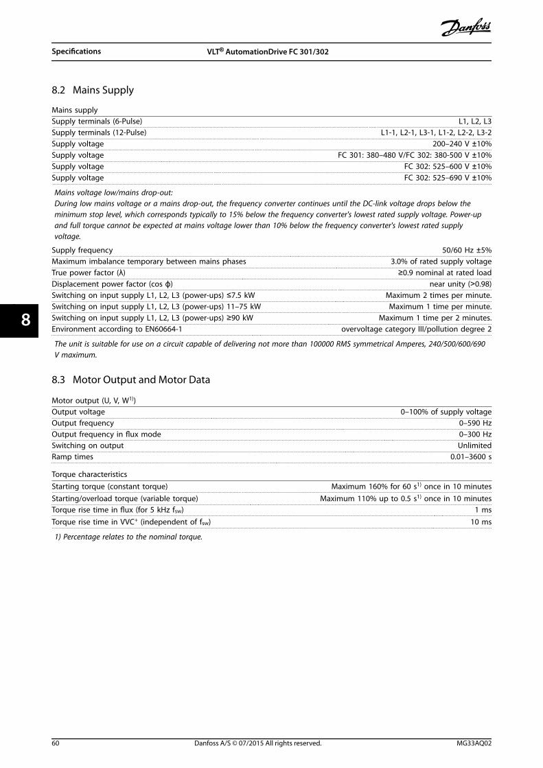
8.2 Mains Supply
Mains supplySupply terminals (6-Pulse) L1, L2, L3Supply terminals (12-Pulse) L1-1, L2-1, L3-1, L1-2, L2-2, L3-2Supply voltage 200–240 V ±10%Supply voltage FC 301: 380–480 V/FC 302: 380-500 V ±10%Supply voltage FC 302: 525–600 V ±10%Supply voltage FC 302: 525–690 V ±10%
Mains voltage low/mains drop-out:During low mains voltage or a mains drop-out, the frequency converter continues until the DC-link voltage drops below theminimum stop level, which corresponds typically to 15% below the frequency converter's lowest rated supply voltage. Power-upand full torque cannot be expected at mains voltage lower than 10% below the frequency converter's lowest rated supplyvoltage.
Supply frequency 50/60 Hz ±5%Maximum imbalance temporary between mains phases 3.0% of rated supply voltageTrue power factor (λ) ≥0.9 nominal at rated loadDisplacement power factor (cos ϕ) near unity (>0.98)Switching on input supply L1, L2, L3 (power-ups) ≤7.5 kW Maximum 2 times per minute.Switching on input supply L1, L2, L3 (power-ups) 11–75 kW Maximum 1 time per minute.Switching on input supply L1, L2, L3 (power-ups) ≥90 kW Maximum 1 time per 2 minutes.Environment according to EN60664-1 overvoltage category III/pollution degree 2
The unit is suitable for use on a circuit capable of delivering not more than 100000 RMS symmetrical Amperes, 240/500/600/690V maximum.
8.3 Motor Output and Motor Data
Motor output (U, V, W1))Output voltage 0–100% of supply voltageOutput frequency 0–590 HzOutput frequency in flux mode 0–300 HzSwitching on output UnlimitedRamp times 0.01–3600 s
Torque characteristicsStarting torque (constant torque) Maximum 160% for 60 s1) once in 10 minutesStarting/overload torque (variable torque) Maximum 110% up to 0.5 s1) once in 10 minutesTorque rise time in flux (for 5 kHz fsw) 1 msTorque rise time in VVC+ (independent of fsw) 10 ms
1) Percentage relates to the nominal torque.
Specifications VLT® AutomationDrive FC 301/302
60 Danfoss A/S © 07/2015 All rights reserved. MG33AQ02
88
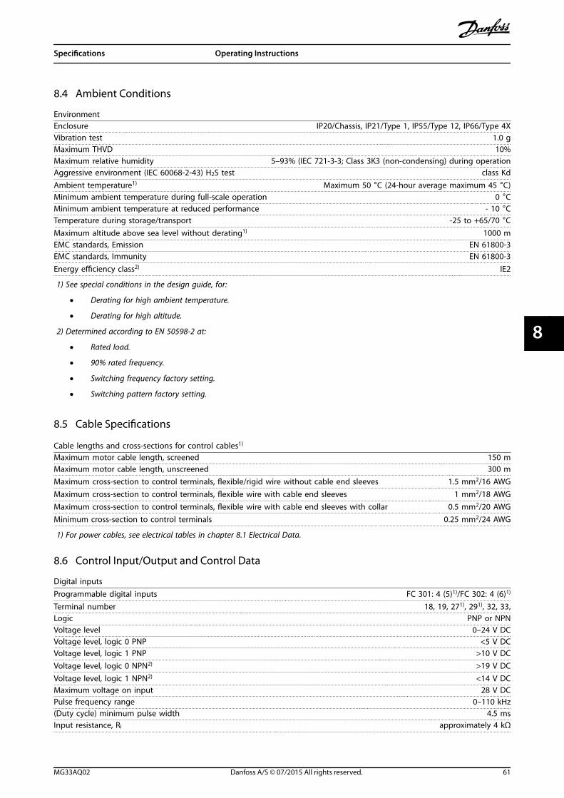
8.4 Ambient Conditions
EnvironmentEnclosure IP20/Chassis, IP21/Type 1, IP55/Type 12, IP66/Type 4XVibration test 1.0 gMaximum THVD 10%Maximum relative humidity 5–93% (IEC 721-3-3; Class 3K3 (non-condensing) during operationAggressive environment (IEC 60068-2-43) H2S test class KdAmbient temperature1) Maximum 50 °C (24-hour average maximum 45 °C)Minimum ambient temperature during full-scale operation 0 °CMinimum ambient temperature at reduced performance - 10 °CTemperature during storage/transport -25 to +65/70 °CMaximum altitude above sea level without derating1) 1000 mEMC standards, Emission EN 61800-3EMC standards, Immunity EN 61800-3Energy efficiency class2) IE2
1) See special conditions in the design guide, for:
• Derating for high ambient temperature.
• Derating for high altitude.
2) Determined according to EN 50598-2 at:
• Rated load.
• 90% rated frequency.
• Switching frequency factory setting.
• Switching pattern factory setting.
8.5 Cable Specifications
Cable lengths and cross-sections for control cables1)
Maximum motor cable length, screened 150 mMaximum motor cable length, unscreened 300 mMaximum cross-section to control terminals, flexible/rigid wire without cable end sleeves 1.5 mm2/16 AWGMaximum cross-section to control terminals, flexible wire with cable end sleeves 1 mm2/18 AWGMaximum cross-section to control terminals, flexible wire with cable end sleeves with collar 0.5 mm2/20 AWGMinimum cross-section to control terminals 0.25 mm2/24 AWG
1) For power cables, see electrical tables in chapter 8.1 Electrical Data.
8.6 Control Input/Output and Control Data
Digital inputsProgrammable digital inputs FC 301: 4 (5)1)/FC 302: 4 (6)1)
Terminal number 18, 19, 271), 291), 32, 33,Logic PNP or NPNVoltage level 0–24 V DCVoltage level, logic 0 PNP <5 V DCVoltage level, logic 1 PNP >10 V DCVoltage level, logic 0 NPN2) >19 V DCVoltage level, logic 1 NPN2) <14 V DCMaximum voltage on input 28 V DCPulse frequency range 0–110 kHz(Duty cycle) minimum pulse width 4.5 msInput resistance, Ri approximately 4 kΩ
Specifications Operating Instructions
MG33AQ02 Danfoss A/S © 07/2015 All rights reserved. 61
8 8
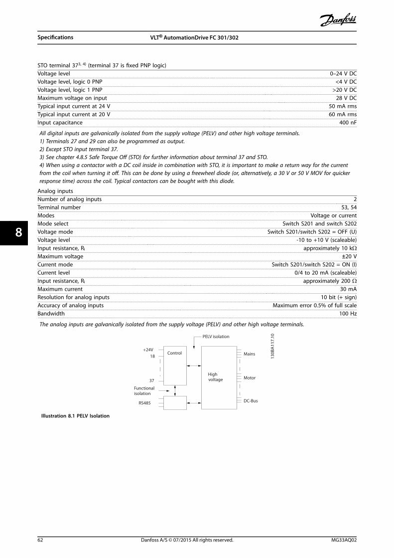
STO terminal 373, 4) (terminal 37 is fixed PNP logic)Voltage level 0–24 V DCVoltage level, logic 0 PNP <4 V DCVoltage level, logic 1 PNP >20 V DCMaximum voltage on input 28 V DCTypical input current at 24 V 50 mA rmsTypical input current at 20 V 60 mA rmsInput capacitance 400 nF
All digital inputs are galvanically isolated from the supply voltage (PELV) and other high voltage terminals.1) Terminals 27 and 29 can also be programmed as output.2) Except STO input terminal 37.3) See chapter 4.8.5 Safe Torque Off (STO) for further information about terminal 37 and STO.4) When using a contactor with a DC coil inside in combination with STO, it is important to make a return way for the currentfrom the coil when turning it off. This can be done by using a freewheel diode (or, alternatively, a 30 V or 50 V MOV for quickerresponse time) across the coil. Typical contactors can be bought with this diode.
Analog inputsNumber of analog inputs 2Terminal number 53, 54Modes Voltage or currentMode select Switch S201 and switch S202Voltage mode Switch S201/switch S202 = OFF (U)Voltage level -10 to +10 V (scaleable)Input resistance, Ri approximately 10 kΩMaximum voltage ±20 VCurrent mode Switch S201/switch S202 = ON (I)Current level 0/4 to 20 mA (scaleable)Input resistance, Ri approximately 200 ΩMaximum current 30 mAResolution for analog inputs 10 bit (+ sign)Accuracy of analog inputs Maximum error 0.5% of full scaleBandwidth 100 Hz
The analog inputs are galvanically isolated from the supply voltage (PELV) and other high voltage terminals.
Mains
Functionalisolation
PELV isolation
Motor
DC-Bus
Highvoltage
Control+24V
RS485
18
37
130B
A11
7.10
Illustration 8.1 PELV Isolation
Specifications VLT® AutomationDrive FC 301/302
62 Danfoss A/S © 07/2015 All rights reserved. MG33AQ02
88
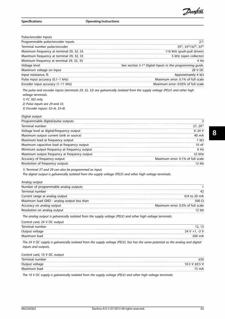
Pulse/encoder inputsProgrammable pulse/encoder inputs 2/1Terminal number pulse/encoder 291), 332)/323), 333)
Maximum frequency at terminal 29, 32, 33 110 kHz (push-pull driven)Maximum frequency at terminal 29, 32, 33 5 kHz (open collector)Minimum frequency at terminal 29, 32, 33 4 HzVoltage level See section 5-1* Digital Inputs in the programming guide.Maximum voltage on input 28 V DCInput resistance, Ri Approximately 4 kΩPulse input accuracy (0.1–1 kHz) Maximum error: 0.1% of full scaleEncoder input accuracy (1–11 kHz) Maximum error: 0.05% of full scale
The pulse and encoder inputs (terminals 29, 32, 33) are galvanically isolated from the supply voltage (PELV) and other highvoltage terminals.1) FC 302 only.2) Pulse inputs are 29 and 33.3) Encoder inputs: 32=A, 33=B.
Digital outputProgrammable digital/pulse outputs 2Terminal number 27, 291)
Voltage level at digital/frequency output 0–24 VMaximum output current (sink or source) 40 mAMaximum load at frequency output 1 kΩMaximum capacitive load at frequency output 10 nFMinimum output frequency at frequency output 0 HzMaximum output frequency at frequency output 32 kHzAccuracy of frequency output Maximum error: 0.1% of full scaleResolution of frequency outputs 12 bit
1) Terminal 27 and 29 can also be programmed as input.The digital output is galvanically isolated from the supply voltage (PELV) and other high voltage terminals.
Analog outputNumber of programmable analog outputs 1Terminal number 42Current range at analog output 0/4 to 20 mAMaximum load GND - analog output less than 500 ΩAccuracy on analog output Maximum error: 0.5% of full scaleResolution on analog output 12 bit
The analog output is galvanically isolated from the supply voltage (PELV) and other high voltage terminals.
Control card, 24 V DC outputTerminal number 12, 13Output voltage 24 V +1, -3 VMaximum load 200 mA
The 24 V DC supply is galvanically isolated from the supply voltage (PELV), but has the same potential as the analog and digitalinputs and outputs.
Control card, 10 V DC outputTerminal number ±50Output voltage 10.5 V ±0.5 VMaximum load 15 mA
The 10 V DC supply is galvanically isolated from the supply voltage (PELV) and other high voltage terminals.
Specifications Operating Instructions
MG33AQ02 Danfoss A/S © 07/2015 All rights reserved. 63
8 8
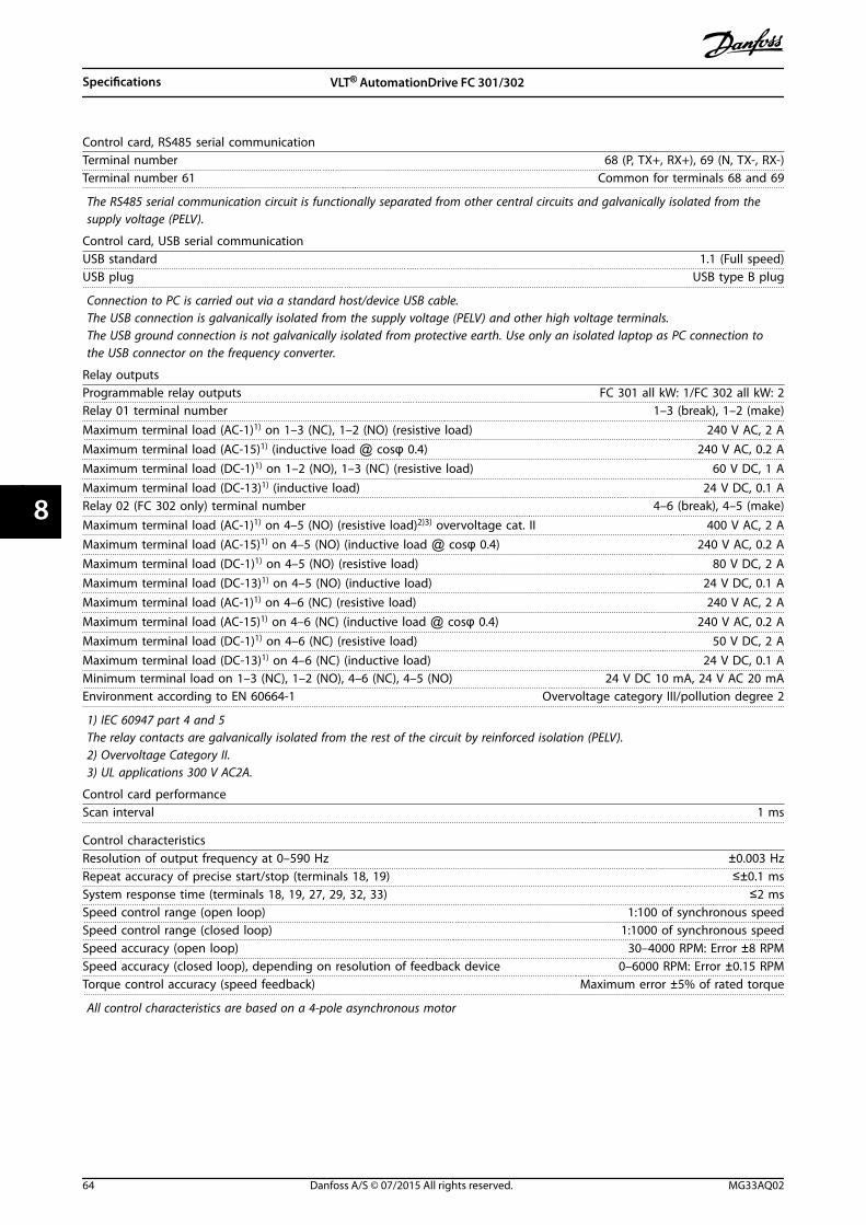
Control card, RS485 serial communicationTerminal number 68 (P, TX+, RX+), 69 (N, TX-, RX-)Terminal number 61 Common for terminals 68 and 69
The RS485 serial communication circuit is functionally separated from other central circuits and galvanically isolated from thesupply voltage (PELV).
Control card, USB serial communication USB standard 1.1 (Full speed)USB plug USB type B plug
Connection to PC is carried out via a standard host/device USB cable.The USB connection is galvanically isolated from the supply voltage (PELV) and other high voltage terminals.The USB ground connection is not galvanically isolated from protective earth. Use only an isolated laptop as PC connection tothe USB connector on the frequency converter.
Relay outputsProgrammable relay outputs FC 301 all kW: 1/FC 302 all kW: 2Relay 01 terminal number 1–3 (break), 1–2 (make)Maximum terminal load (AC-1)1) on 1–3 (NC), 1–2 (NO) (resistive load) 240 V AC, 2 AMaximum terminal load (AC-15)1) (inductive load @ cosφ 0.4) 240 V AC, 0.2 AMaximum terminal load (DC-1)1) on 1–2 (NO), 1–3 (NC) (resistive load) 60 V DC, 1 AMaximum terminal load (DC-13)1) (inductive load) 24 V DC, 0.1 ARelay 02 (FC 302 only) terminal number 4–6 (break), 4–5 (make)Maximum terminal load (AC-1)1) on 4–5 (NO) (resistive load)2)3) overvoltage cat. II 400 V AC, 2 AMaximum terminal load (AC-15)1) on 4–5 (NO) (inductive load @ cosφ 0.4) 240 V AC, 0.2 AMaximum terminal load (DC-1)1) on 4–5 (NO) (resistive load) 80 V DC, 2 AMaximum terminal load (DC-13)1) on 4–5 (NO) (inductive load) 24 V DC, 0.1 AMaximum terminal load (AC-1)1) on 4–6 (NC) (resistive load) 240 V AC, 2 AMaximum terminal load (AC-15)1) on 4–6 (NC) (inductive load @ cosφ 0.4) 240 V AC, 0.2 AMaximum terminal load (DC-1)1) on 4–6 (NC) (resistive load) 50 V DC, 2 AMaximum terminal load (DC-13)1) on 4–6 (NC) (inductive load) 24 V DC, 0.1 AMinimum terminal load on 1–3 (NC), 1–2 (NO), 4–6 (NC), 4–5 (NO) 24 V DC 10 mA, 24 V AC 20 mAEnvironment according to EN 60664-1 Overvoltage category III/pollution degree 2
1) IEC 60947 part 4 and 5The relay contacts are galvanically isolated from the rest of the circuit by reinforced isolation (PELV).2) Overvoltage Category II.3) UL applications 300 V AC2A.
Control card performanceScan interval 1 ms
Control characteristicsResolution of output frequency at 0–590 Hz ±0.003 HzRepeat accuracy of precise start/stop (terminals 18, 19) ≤±0.1 msSystem response time (terminals 18, 19, 27, 29, 32, 33) ≤2 msSpeed control range (open loop) 1:100 of synchronous speedSpeed control range (closed loop) 1:1000 of synchronous speedSpeed accuracy (open loop) 30–4000 RPM: Error ±8 RPMSpeed accuracy (closed loop), depending on resolution of feedback device 0–6000 RPM: Error ±0.15 RPMTorque control accuracy (speed feedback) Maximum error ±5% of rated torque
All control characteristics are based on a 4-pole asynchronous motor
Specifications VLT® AutomationDrive FC 301/302
64 Danfoss A/S © 07/2015 All rights reserved. MG33AQ02
88
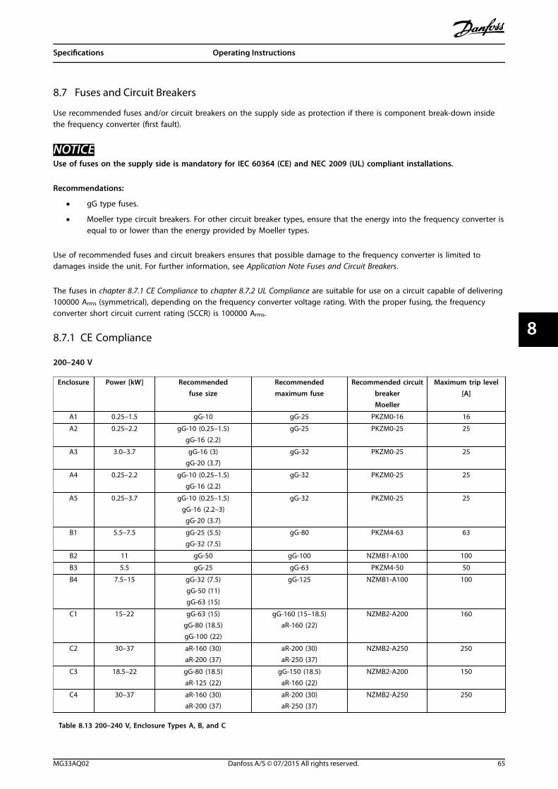
8.7 Fuses and Circuit Breakers
Use recommended fuses and/or circuit breakers on the supply side as protection if there is component break-down insidethe frequency converter (first fault).
NOTICEUse of fuses on the supply side is mandatory for IEC 60364 (CE) and NEC 2009 (UL) compliant installations.
Recommendations:
• gG type fuses.
• Moeller type circuit breakers. For other circuit breaker types, ensure that the energy into the frequency converter isequal to or lower than the energy provided by Moeller types.
Use of recommended fuses and circuit breakers ensures that possible damage to the frequency converter is limited todamages inside the unit. For further information, see Application Note Fuses and Circuit Breakers.
The fuses in chapter 8.7.1 CE Compliance to chapter 8.7.2 UL Compliance are suitable for use on a circuit capable of delivering100000 Arms (symmetrical), depending on the frequency converter voltage rating. With the proper fusing, the frequencyconverter short circuit current rating (SCCR) is 100000 Arms.
8.7.1 CE Compliance
200–240 V
Enclosure Power [kW] Recommendedfuse size
Recommendedmaximum fuse
Recommended circuitbreakerMoeller
Maximum trip level[A]
A1 0.25–1.5 gG-10 gG-25 PKZM0-16 16
A2 0.25–2.2 gG-10 (0.25–1.5)gG-16 (2.2)
gG-25 PKZM0-25 25
A3 3.0–3.7 gG-16 (3)gG-20 (3.7)
gG-32 PKZM0-25 25
A4 0.25–2.2 gG-10 (0.25–1.5)gG-16 (2.2)
gG-32 PKZM0-25 25
A5 0.25–3.7 gG-10 (0.25–1.5)gG-16 (2.2–3)
gG-20 (3.7)
gG-32 PKZM0-25 25
B1 5.5–7.5 gG-25 (5.5)gG-32 (7.5)
gG-80 PKZM4-63 63
B2 11 gG-50 gG-100 NZMB1-A100 100
B3 5.5 gG-25 gG-63 PKZM4-50 50
B4 7.5–15 gG-32 (7.5)gG-50 (11)gG-63 (15)
gG-125 NZMB1-A100 100
C1 15–22 gG-63 (15)gG-80 (18.5)gG-100 (22)
gG-160 (15–18.5)aR-160 (22)
NZMB2-A200 160
C2 30–37 aR-160 (30)aR-200 (37)
aR-200 (30)aR-250 (37)
NZMB2-A250 250
C3 18.5–22 gG-80 (18.5)aR-125 (22)
gG-150 (18.5)aR-160 (22)
NZMB2-A200 150
C4 30–37 aR-160 (30)aR-200 (37)
aR-200 (30)aR-250 (37)
NZMB2-A250 250
Table 8.13 200–240 V, Enclosure Types A, B, and C
Specifications Operating Instructions
MG33AQ02 Danfoss A/S © 07/2015 All rights reserved. 65
8 8
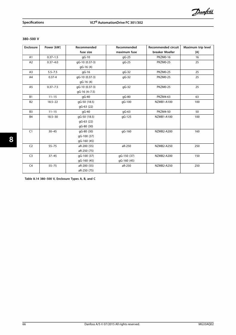
380–500 V
Enclosure Power [kW] Recommendedfuse size
Recommendedmaximum fuse
Recommended circuitbreaker Moeller
Maximum trip level[A]
A1 0.37–1.5 gG-10 gG-25 PKZM0-16 16
A2 0.37–4.0 gG-10 (0.37-3)gG-16 (4)
gG-25 PKZM0-25 25
A3 5.5–7.5 gG-16 gG-32 PKZM0-25 25
A4 0.37-4 gG-10 (0.37-3)gG-16 (4)
gG-32 PKZM0-25 25
A5 0.37–7.5 gG-10 (0.37-3)gG-16 (4–7.5)
gG-32 PKZM0-25 25
B1 11–15 gG-40 gG-80 PKZM4-63 63
B2 18.5–22 gG-50 (18.5)gG-63 (22)
gG-100 NZMB1-A100 100
B3 11–15 gG-40 gG-63 PKZM4-50 50
B4 18.5–30 gG-50 (18.5)gG-63 (22)gG-80 (30)
gG-125 NZMB1-A100 100
C1 30–45 gG-80 (30)gG-100 (37)gG-160 (45)
gG-160 NZMB2-A200 160
C2 55–75 aR-200 (55)aR-250 (75)
aR-250 NZMB2-A250 250
C3 37–45 gG-100 (37)gG-160 (45)
gG-150 (37)gG-160 (45)
NZMB2-A200 150
C4 55–75 aR-200 (55)aR-250 (75)
aR-250 NZMB2-A250 250
Table 8.14 380–500 V, Enclosure Types A, B, and C
Specifications VLT® AutomationDrive FC 301/302
66 Danfoss A/S © 07/2015 All rights reserved. MG33AQ02
88
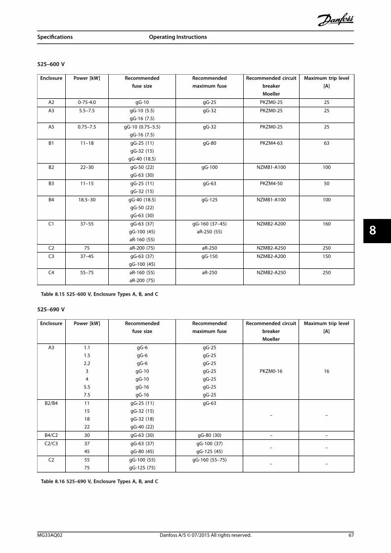
525–600 V
Enclosure Power [kW] Recommendedfuse size
Recommendedmaximum fuse
Recommended circuitbreakerMoeller
Maximum trip level[A]
A2 0-75-4.0 gG-10 gG-25 PKZM0-25 25
A3 5.5–7.5 gG-10 (5.5)gG-16 (7.5)
gG-32 PKZM0-25 25
A5 0.75–7.5 gG-10 (0.75–5.5)gG-16 (7.5)
gG-32 PKZM0-25 25
B1 11–18 gG-25 (11)gG-32 (15)
gG-40 (18.5)
gG-80 PKZM4-63 63
B2 22–30 gG-50 (22)gG-63 (30)
gG-100 NZMB1-A100 100
B3 11–15 gG-25 (11)gG-32 (15)
gG-63 PKZM4-50 50
B4 18.5–30 gG-40 (18.5)gG-50 (22)gG-63 (30)
gG-125 NZMB1-A100 100
C1 37–55 gG-63 (37)gG-100 (45)aR-160 (55)
gG-160 (37–45)aR-250 (55)
NZMB2-A200 160
C2 75 aR-200 (75) aR-250 NZMB2-A250 250
C3 37–45 gG-63 (37)gG-100 (45)
gG-150 NZMB2-A200 150
C4 55–75 aR-160 (55)aR-200 (75)
aR-250 NZMB2-A250 250
Table 8.15 525–600 V, Enclosure Types A, B, and C
525–690 V
Enclosure Power [kW] Recommendedfuse size
Recommendedmaximum fuse
Recommended circuitbreakerMoeller
Maximum trip level[A]
A3 1.11.52.234
5.57.5
gG-6gG-6gG-6
gG-10gG-10gG-16gG-16
gG-25gG-25gG-25gG-25gG-25gG-25gG-25
PKZM0-16 16
B2/B4 11151822
gG-25 (11)gG-32 (15)gG-32 (18)gG-40 (22)
gG-63
– –
B4/C2 30 gG-63 (30) gG-80 (30) – –
C2/C3 3745
gG-63 (37)gG-80 (45)
gG-100 (37)gG-125 (45)
– –
C2 5575
gG-100 (55)gG-125 (75)
gG-160 (55–75)– –
Table 8.16 525–690 V, Enclosure Types A, B, and C
Specifications Operating Instructions
MG33AQ02 Danfoss A/S © 07/2015 All rights reserved. 67
8 8
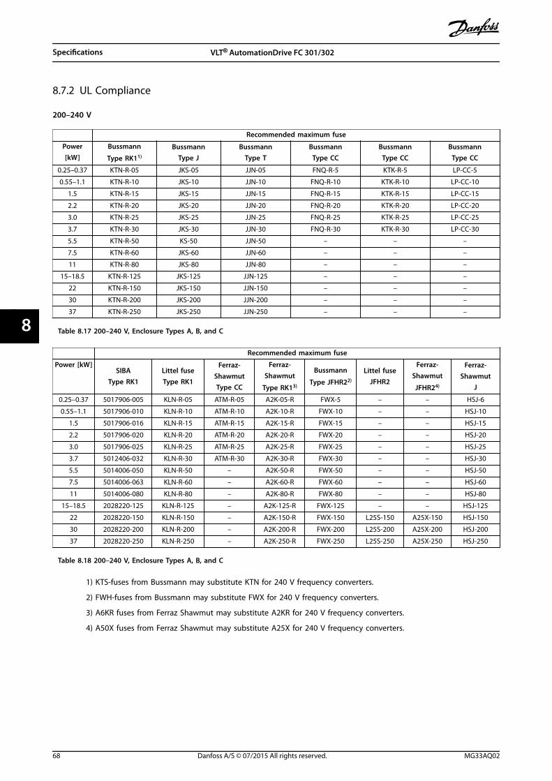
8.7.2 UL Compliance
200–240 V
Recommended maximum fuse
Power[kW]
Bussmann
Type RK11)
BussmannType J
BussmannType T
BussmannType CC
BussmannType CC
BussmannType CC
0.25–0.37 KTN-R-05 JKS-05 JJN-05 FNQ-R-5 KTK-R-5 LP-CC-5
0.55–1.1 KTN-R-10 JKS-10 JJN-10 FNQ-R-10 KTK-R-10 LP-CC-10
1.5 KTN-R-15 JKS-15 JJN-15 FNQ-R-15 KTK-R-15 LP-CC-15
2.2 KTN-R-20 JKS-20 JJN-20 FNQ-R-20 KTK-R-20 LP-CC-20
3.0 KTN-R-25 JKS-25 JJN-25 FNQ-R-25 KTK-R-25 LP-CC-25
3.7 KTN-R-30 JKS-30 JJN-30 FNQ-R-30 KTK-R-30 LP-CC-30
5.5 KTN-R-50 KS-50 JJN-50 – – –
7.5 KTN-R-60 JKS-60 JJN-60 – – –
11 KTN-R-80 JKS-80 JJN-80 – – –
15–18.5 KTN-R-125 JKS-125 JJN-125 – – –
22 KTN-R-150 JKS-150 JJN-150 – – –
30 KTN-R-200 JKS-200 JJN-200 – – –
37 KTN-R-250 JKS-250 JJN-250 – – –
Table 8.17 200–240 V, Enclosure Types A, B, and C
Recommended maximum fuse
Power [kW]SIBA
Type RK1Littel fuseType RK1
Ferraz-ShawmutType CC
Ferraz-Shawmut
Type RK13)
Bussmann
Type JFHR22)
Littel fuseJFHR2
Ferraz-Shawmut
JFHR24)
Ferraz-Shawmut
J
0.25–0.37 5017906-005 KLN-R-05 ATM-R-05 A2K-05-R FWX-5 – – HSJ-6
0.55–1.1 5017906-010 KLN-R-10 ATM-R-10 A2K-10-R FWX-10 – – HSJ-10
1.5 5017906-016 KLN-R-15 ATM-R-15 A2K-15-R FWX-15 – – HSJ-15
2.2 5017906-020 KLN-R-20 ATM-R-20 A2K-20-R FWX-20 – – HSJ-20
3.0 5017906-025 KLN-R-25 ATM-R-25 A2K-25-R FWX-25 – – HSJ-25
3.7 5012406-032 KLN-R-30 ATM-R-30 A2K-30-R FWX-30 – – HSJ-30
5.5 5014006-050 KLN-R-50 – A2K-50-R FWX-50 – – HSJ-50
7.5 5014006-063 KLN-R-60 – A2K-60-R FWX-60 – – HSJ-60
11 5014006-080 KLN-R-80 – A2K-80-R FWX-80 – – HSJ-80
15–18.5 2028220-125 KLN-R-125 – A2K-125-R FWX-125 – – HSJ-125
22 2028220-150 KLN-R-150 – A2K-150-R FWX-150 L25S-150 A25X-150 HSJ-150
30 2028220-200 KLN-R-200 – A2K-200-R FWX-200 L25S-200 A25X-200 HSJ-200
37 2028220-250 KLN-R-250 – A2K-250-R FWX-250 L25S-250 A25X-250 HSJ-250
Table 8.18 200–240 V, Enclosure Types A, B, and C
1) KTS-fuses from Bussmann may substitute KTN for 240 V frequency converters.
2) FWH-fuses from Bussmann may substitute FWX for 240 V frequency converters.
3) A6KR fuses from Ferraz Shawmut may substitute A2KR for 240 V frequency converters.
4) A50X fuses from Ferraz Shawmut may substitute A25X for 240 V frequency converters.
Specifications VLT® AutomationDrive FC 301/302
68 Danfoss A/S © 07/2015 All rights reserved. MG33AQ02
88
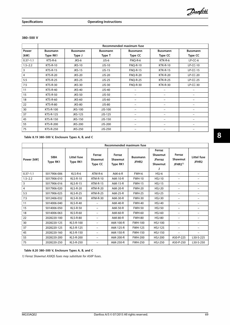
380–500 V
Recommended maximum fuse
Power[kW]
BussmannType RK1
BussmannType J
BussmannType T
BussmannType CC
BussmannType CC
BussmannType CC
0.37–1.1 KTS-R-6 JKS-6 JJS-6 FNQ-R-6 KTK-R-6 LP-CC-6
1.5–2.2 KTS-R-10 JKS-10 JJS-10 FNQ-R-10 KTK-R-10 LP-CC-10
3 KTS-R-15 JKS-15 JJS-15 FNQ-R-15 KTK-R-15 LP-CC-15
4 KTS-R-20 JKS-20 JJS-20 FNQ-R-20 KTK-R-20 LP-CC-20
5.5 KTS-R-25 JKS-25 JJS-25 FNQ-R-25 KTK-R-25 LP-CC-25
7.5 KTS-R-30 JKS-30 JJS-30 FNQ-R-30 KTK-R-30 LP-CC-30
11 KTS-R-40 JKS-40 JJS-40 – – –
15 KTS-R-50 JKS-50 JJS-50 – – –
18 KTS-R-60 JKS-60 JJS-60 – – –
22 KTS-R-80 JKS-80 JJS-80 – – –
30 KTS-R-100 JKS-100 JJS-100 – – –
37 KTS-R-125 JKS-125 JJS-125 – – –
45 KTS-R-150 JKS-150 JJS-150 – – –
55 KTS-R-200 JKS-200 JJS-200 – – –
75 KTS-R-250 JKS-250 JJS-250 – – –
Table 8.19 380–500 V, Enclosure Types A, B, and C
Recommended maximum fuse
Power [kW]SIBA
Type RK1Littel fuseType RK1
FerrazShawmutType CC
FerrazShawmutType RK1
BussmannJFHR2
FerrazShawmut
JFerrazShawmut
J
FerrazShawmut
JFHR21)
Littel fuseJFHR2
0.37–1.1 5017906-006 KLS-R-6 ATM-R-6 A6K-6-R FWH-6 HSJ-6 – –
1.5–2.2 5017906-010 KLS-R-10 ATM-R-10 A6K-10-R FWH-10 HSJ-10 – –
3 5017906-016 KLS-R-15 ATM-R-15 A6K-15-R FWH-15 HSJ-15 – –
4 5017906-020 KLS-R-20 ATM-R-20 A6K-20-R FWH-20 HSJ-20 – –
5.5 5017906-025 KLS-R-25 ATM-R-25 A6K-25-R FWH-25 HSJ-25 – –
7.5 5012406-032 KLS-R-30 ATM-R-30 A6K-30-R FWH-30 HSJ-30 – –
11 5014006-040 KLS-R-40 – A6K-40-R FWH-40 HSJ-40 – –
15 5014006-050 KLS-R-50 – A6K-50-R FWH-50 HSJ-50 – –
18 5014006-063 KLS-R-60 – A6K-60-R FWH-60 HSJ-60 – –
22 2028220-100 KLS-R-80 – A6K-80-R FWH-80 HSJ-80 – –
30 2028220-125 KLS-R-100 – A6K-100-R FWH-100 HSJ-100 – –
37 2028220-125 KLS-R-125 – A6K-125-R FWH-125 HSJ-125 – –
45 2028220-160 KLS-R-150 – A6K-150-R FWH-150 HSJ-150 – –
55 2028220-200 KLS-R-200 – A6K-200-R FWH-200 HSJ-200 A50-P-225 L50-S-225
75 2028220-250 KLS-R-250 – A6K-250-R FWH-250 HSJ-250 A50-P-250 L50-S-250
Table 8.20 380–500 V, Enclosure Types A, B, and C
1) Ferraz Shawmut A50QS fuses may substitute for A50P fuses.
Specifications Operating Instructions
MG33AQ02 Danfoss A/S © 07/2015 All rights reserved. 69
8 8
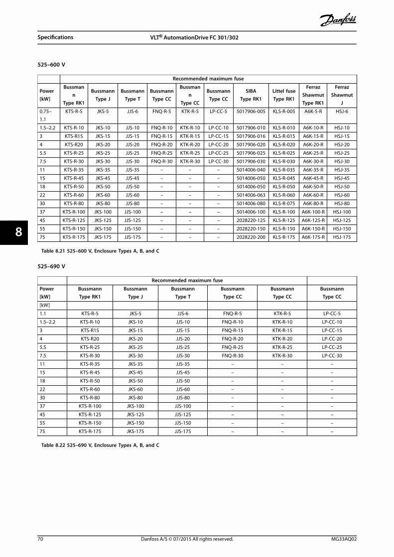
525–600 V
Recommended maximum fuse
Power[kW]
Bussmann
Type RK1
BussmannType J
BussmannType T
BussmannType CC
Bussmann
Type CC
BussmannType CC
SIBAType RK1
Littel fuseType RK1
FerrazShawmutType RK1
FerrazShawmut
J
0.75–1.1
KTS-R-5 JKS-5 JJS-6 FNQ-R-5 KTK-R-5 LP-CC-5 5017906-005 KLS-R-005 A6K-5-R HSJ-6
1.5–2.2 KTS-R-10 JKS-10 JJS-10 FNQ-R-10 KTK-R-10 LP-CC-10 5017906-010 KLS-R-010 A6K-10-R HSJ-10
3 KTS-R15 JKS-15 JJS-15 FNQ-R-15 KTK-R-15 LP-CC-15 5017906-016 KLS-R-015 A6K-15-R HSJ-15
4 KTS-R20 JKS-20 JJS-20 FNQ-R-20 KTK-R-20 LP-CC-20 5017906-020 KLS-R-020 A6K-20-R HSJ-20
5.5 KTS-R-25 JKS-25 JJS-25 FNQ-R-25 KTK-R-25 LP-CC-25 5017906-025 KLS-R-025 A6K-25-R HSJ-25
7.5 KTS-R-30 JKS-30 JJS-30 FNQ-R-30 KTK-R-30 LP-CC-30 5017906-030 KLS-R-030 A6K-30-R HSJ-30
11 KTS-R-35 JKS-35 JJS-35 – – – 5014006-040 KLS-R-035 A6K-35-R HSJ-35
15 KTS-R-45 JKS-45 JJS-45 – – – 5014006-050 KLS-R-045 A6K-45-R HSJ-45
18 KTS-R-50 JKS-50 JJS-50 – – – 5014006-050 KLS-R-050 A6K-50-R HSJ-50
22 KTS-R-60 JKS-60 JJS-60 – – – 5014006-063 KLS-R-060 A6K-60-R HSJ-60
30 KTS-R-80 JKS-80 JJS-80 – – – 5014006-080 KLS-R-075 A6K-80-R HSJ-80
37 KTS-R-100 JKS-100 JJS-100 – – – 5014006-100 KLS-R-100 A6K-100-R HSJ-100
45 KTS-R-125 JKS-125 JJS-125 – – – 2028220-125 KLS-R-125 A6K-125-R HSJ-125
55 KTS-R-150 JKS-150 JJS-150 – – – 2028220-150 KLS-R-150 A6K-150-R HSJ-150
75 KTS-R-175 JKS-175 JJS-175 – – – 2028220-200 KLS-R-175 A6K-175-R HSJ-175
Table 8.21 525–600 V, Enclosure Types A, B, and C
525–690 V
Recommended maximum fuse
Power[kW]
BussmannType RK1
BussmannType J
BussmannType T
BussmannType CC
BussmannType CC
BussmannType CC
[kW]
1.1 KTS-R-5 JKS-5 JJS-6 FNQ-R-5 KTK-R-5 LP-CC-5
1.5–2.2 KTS-R-10 JKS-10 JJS-10 FNQ-R-10 KTK-R-10 LP-CC-10
3 KTS-R15 JKS-15 JJS-15 FNQ-R-15 KTK-R-15 LP-CC-15
4 KTS-R20 JKS-20 JJS-20 FNQ-R-20 KTK-R-20 LP-CC-20
5.5 KTS-R-25 JKS-25 JJS-25 FNQ-R-25 KTK-R-25 LP-CC-25
7.5 KTS-R-30 JKS-30 JJS-30 FNQ-R-30 KTK-R-30 LP-CC-30
11 KTS-R-35 JKS-35 JJS-35 – – –
15 KTS-R-45 JKS-45 JJS-45 – – –
18 KTS-R-50 JKS-50 JJS-50 – – –
22 KTS-R-60 JKS-60 JJS-60 – – –
30 KTS-R-80 JKS-80 JJS-80 – – –
37 KTS-R-100 JKS-100 JJS-100 – – –
45 KTS-R-125 JKS-125 JJS-125 – – –
55 KTS-R-150 JKS-150 JJS-150 – – –
75 KTS-R-175 JKS-175 JJS-175 – – –
Table 8.22 525–690 V, Enclosure Types A, B, and C
Specifications VLT® AutomationDrive FC 301/302
70 Danfoss A/S © 07/2015 All rights reserved. MG33AQ02
88
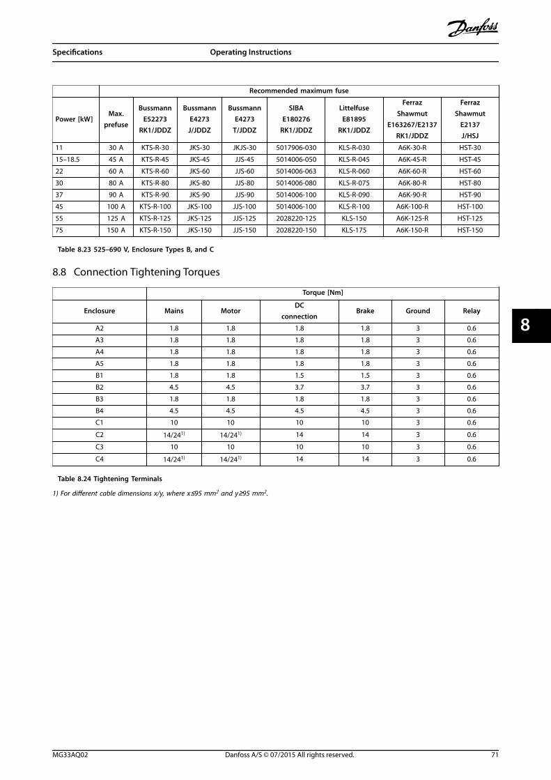
Recommended maximum fuse
Power [kW]Max.
prefuse
BussmannE52273
RK1/JDDZ
BussmannE4273J/JDDZ
BussmannE4273
T/JDDZ
SIBAE180276
RK1/JDDZ
LittelfuseE81895
RK1/JDDZ
FerrazShawmut
E163267/E2137RK1/JDDZ
FerrazShawmut
E2137J/HSJ
11 30 A KTS-R-30 JKS-30 JKJS-30 5017906-030 KLS-R-030 A6K-30-R HST-30
15–18.5 45 A KTS-R-45 JKS-45 JJS-45 5014006-050 KLS-R-045 A6K-45-R HST-45
22 60 A KTS-R-60 JKS-60 JJS-60 5014006-063 KLS-R-060 A6K-60-R HST-60
30 80 A KTS-R-80 JKS-80 JJS-80 5014006-080 KLS-R-075 A6K-80-R HST-80
37 90 A KTS-R-90 JKS-90 JJS-90 5014006-100 KLS-R-090 A6K-90-R HST-90
45 100 A KTS-R-100 JKS-100 JJS-100 5014006-100 KLS-R-100 A6K-100-R HST-100
55 125 A KTS-R-125 JKS-125 JJS-125 2028220-125 KLS-150 A6K-125-R HST-125
75 150 A KTS-R-150 JKS-150 JJS-150 2028220-150 KLS-175 A6K-150-R HST-150
Table 8.23 525–690 V, Enclosure Types B, and C
8.8 Connection Tightening Torques
Torque [Nm]
Enclosure Mains MotorDC
connectionBrake Ground Relay
A2 1.8 1.8 1.8 1.8 3 0.6
A3 1.8 1.8 1.8 1.8 3 0.6
A4 1.8 1.8 1.8 1.8 3 0.6
A5 1.8 1.8 1.8 1.8 3 0.6
B1 1.8 1.8 1.5 1.5 3 0.6
B2 4.5 4.5 3.7 3.7 3 0.6
B3 1.8 1.8 1.8 1.8 3 0.6
B4 4.5 4.5 4.5 4.5 3 0.6
C1 10 10 10 10 3 0.6
C2 14/241) 14/241) 14 14 3 0.6
C3 10 10 10 10 3 0.6
C4 14/241) 14/241) 14 14 3 0.6
Table 8.24 Tightening Terminals
1) For different cable dimensions x/y, where x≤95 mm2 and y≥95 mm2.
Specifications Operating Instructions
MG33AQ02 Danfoss A/S © 07/2015 All rights reserved. 71
8 8
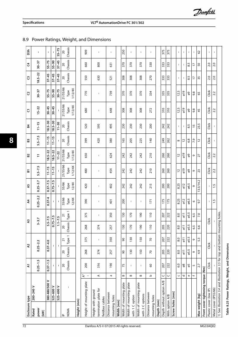
8.9 Power Ratings, Weight, and Dimensions
Encl
osur
e ty
peA
1A
2A
3A
4A
5B1
B2B3
B4C1
C2C3
C4D
3h
Rate
dpo
wer
[kW
]
200–
240
V0.
25–1
.50.
25–2
.23–
3.7
0.25
–2.2
0.25
–3.7
5.5–
7.5
115.
5–7.
511
–15
15–2
230
–37
18.5
–22
30–3
7–
38
0-48
0/50
0 V
0.37
–1.5
0.37
–4.0
5.5–
7.5
0.37
-40.
37–7
.511
–15
18.5
–22
11–1
518
.5–3
030
–45
55–7
537
–45
55–7
5–
52
5–60
0 V
––
0.75
–7.5
–0.
75–7
.511
–15
18.5
–22
11–1
518
.5–3
030
–45
55–9
037
–45
55–9
0–
52
5–69
0 V
––
1.1–
7.5
––
–11
–22
–11
–30
–30
–75
37–4
537
–45
55–7
5
IP NEM
A–
20Ch
assi
s20
Chas
sis
21Ty
pe 1
20Ch
assi
s21
Type
155
/66
Type
12/4
X
55/6
6Ty
pe12
/4X
21/5
5/66
Type
1/12
/4X
21/5
5/66
Type
1/12
/4X
20Ch
assi
s20
Chas
sis
21/5
5/66
Type
1/12
/4X
21/5
5/66
Type
1/12
/4X
20Ch
assi
s20
Chas
sis
20Ch
assi
s
Hei
ght
[mm
]
Hei
ght
of m
ount
ing
pla
teA
1 )20
026
837
526
837
539
042
048
065
039
952
068
077
055
066
090
9
Hei
ght
with
gro
und
term
inat
ion
pla
te fo
rfie
ldbu
s ca
bles
A31
637
4–
374
––
––
–42
059
5–
–63
080
0–
Dis
tanc
e be
twee
nm
ount
ing
hol
esa
190
257
350
257
350
401
402
454
624
380
495
648
739
521
631
–
Wid
th [m
m]
Wid
th o
f m
ount
ing
pla
teB
7590
9013
013
020
024
224
224
216
523
030
837
030
837
025
0
Wid
th o
f m
ount
ing
pla
tew
ith 1
C o
ptio
nB
–13
013
017
017
0–
242
242
242
205
230
308
370
308
370
–
Wid
th o
f m
ount
ing
pla
tew
ith 2
C o
ptio
nsB
–15
015
019
019
0–
242
242
242
225
230
308
370
308
370
–
Dis
tanc
e be
twee
nm
ount
ing
hol
esb
6070
7011
011
017
121
521
021
014
020
027
233
427
033
0–
Dep
th [m
m]
Dep
th w
ithou
t op
tion
A/B
C20
720
520
720
520
717
520
026
026
024
924
231
033
533
333
337
5
With
opt
ion
A/B
C22
222
022
222
022
217
520
026
026
026
224
231
033
533
333
337
5
Scre
w h
oles
[mm
]
c6.
08.
08.
08.
08.
08.
258.
2512
128
–12
.512
.5–
––
dø8
ø11
ø11
ø11
ø11
ø12
ø12
ø19
ø19
12–
ø19
ø19
––
–
eø5
ø5.5
ø5.5
ø5.5
ø5.5
ø6.5
ø6.5
ø9ø9
6.8
8.5
ø9ø9
8.5
8.5
–
f5
99
6.5
6.5
69
99
7.9
159.
89.
817
17–
Max
wei
ght
[kg]
2.7
4.9
5.3
6.6
7.0
9.7
13.5
/14.
223
2712
23.5
4565
3550
62
Fron
t co
ver
tight
enin
g t
orqu
e [N
m]
Plas
tic c
over
(low
IP)
Clic
kCl
ick
Clic
k–
–Cl
ick
Clic
kCl
ick
Clic
kCl
ick
Clic
k2.
02.
0–
Met
al c
over
(IP5
5/66
)–
––
1.5
1.5
2.2
2.2
––
2.2
2.2
2.0
2.0
–
1) S
ee Il
lust
ratio
n 3.
4 an
d Il
lust
ratio
n 3.
5 fo
r to
p a
nd b
otto
m m
ount
ing
hol
es.
Tabl
e 8.
25 P
ower
Rat
ings
, Wei
ght,
and
Dim
ensi
ons
Specifications VLT® AutomationDrive FC 301/302
72 Danfoss A/S © 07/2015 All rights reserved. MG33AQ02
88
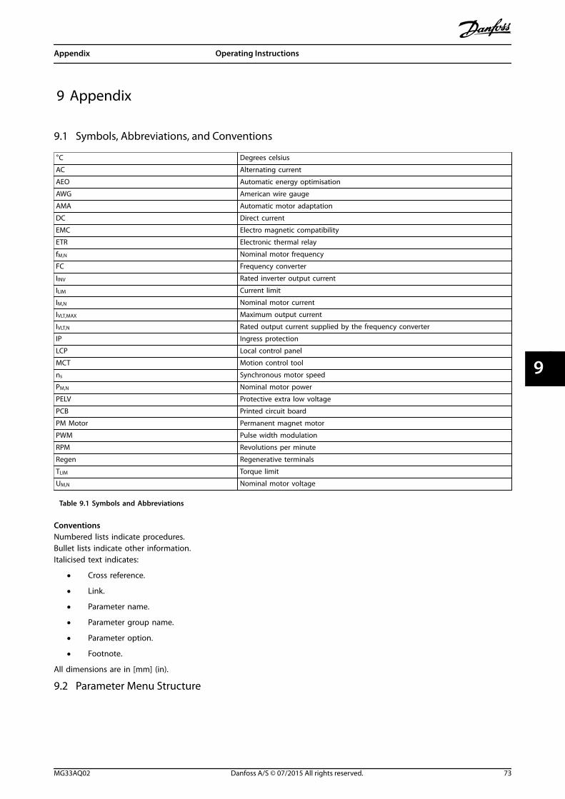
9 Appendix
9.1 Symbols, Abbreviations, and Conventions
°C Degrees celsius
AC Alternating current
AEO Automatic energy optimisation
AWG American wire gauge
AMA Automatic motor adaptation
DC Direct current
EMC Electro magnetic compatibility
ETR Electronic thermal relay
fM,N Nominal motor frequency
FC Frequency converter
IINV Rated inverter output current
ILIM Current limit
IM,N Nominal motor current
IVLT,MAX Maximum output current
IVLT,N Rated output current supplied by the frequency converter
IP Ingress protection
LCP Local control panel
MCT Motion control tool
ns Synchronous motor speed
PM,N Nominal motor power
PELV Protective extra low voltage
PCB Printed circuit board
PM Motor Permanent magnet motor
PWM Pulse width modulation
RPM Revolutions per minute
Regen Regenerative terminals
TLIM Torque limit
UM,N Nominal motor voltage
Table 9.1 Symbols and Abbreviations
ConventionsNumbered lists indicate procedures.Bullet lists indicate other information.Italicised text indicates:
• Cross reference.
• Link.
• Parameter name.
• Parameter group name.
• Parameter option.
• Footnote.
All dimensions are in [mm] (in).
9.2 Parameter Menu Structure
Appendix Operating Instructions
MG33AQ02 Danfoss A/S © 07/2015 All rights reserved. 73
9 9
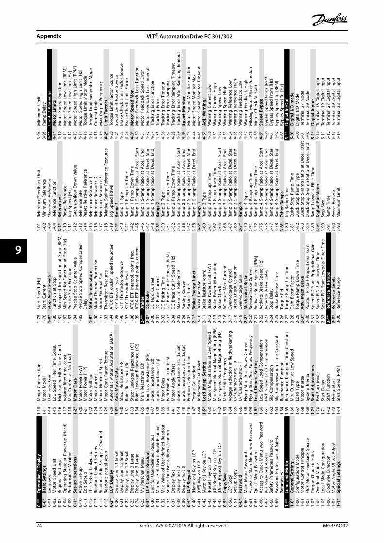
0-**
Ope
ratio
n /
Dis
play
0-0*
Basi
c Se
ttin
gs0-
01La
ngua
ge0-
02M
otor
Spe
ed U
nit
0-03
Regi
onal
Set
tings
0-04
Ope
ratin
g S
tate
at
Pow
er-u
p (H
and)
0-09
Perf
orm
ance
Mon
itor
0-1*
Set-
up O
pera
tions
0-10
Activ
e Se
t-up
0-11
Edit
Set
-up
0-12
This
Set
-up
Lin
ked
to
0-13
Read
out:
Lin
ked
Set
-ups
0-14
Read
out:
Edi
t Se
t-up
s /
Chan
nel
0-15
Read
out:
act
ual s
etup
0-2*
LCP
Dis
play
0-20
Dis
play
Lin
e 1.
1 Sm
all
0-21
Dis
play
Lin
e 1.
2 Sm
all
0-22
Dis
play
Lin
e 1.
3 Sm
all
0-23
Dis
play
Lin
e 2
Larg
e0-
24D
ispl
ay L
ine
3 La
rge
0-25
My
Pers
onal
Men
u0-
3*LC
P C
usto
m R
eado
ut0-
30U
nit
for
Use
r-de
fined
Rea
dout
0-31
Min
Val
ue o
f U
ser-
defin
ed R
eado
ut0-
32M
ax V
alue
of
Use
r-de
fined
Rea
dout
0-33
Sour
ce fo
r U
ser-
defin
ed R
eado
ut0-
37D
ispl
ay T
ext
10-
38D
ispl
ay T
ext
20-
39D
ispl
ay T
ext
30-
4*LC
P K
eypa
d0-
40[H
and
on]
Key
on
LCP
0-41
[Off]
Key
on
LCP
0-42
[Aut
o o
n] K
ey o
n L
CP0-
43[R
eset
] Ke
y on
LCP
0-44
[Off/
Rese
t] K
ey o
n L
CP0-
45[D
rive
Bypa
ss]
Key
on L
CP0-
5*Co
py/S
ave
0-50
LCP
Cop
y0-
51Se
t-up
Cop
y0-
6*Pa
ssw
ord
0-60
Mai
n M
enu
Pas
swor
d0-
61Ac
cess
to
Mai
n M
enu
w/o
Pas
swor
d0-
65Q
uick
Men
u P
assw
ord
0-66
Acce
ss t
o Q
uick
Men
u w
/o P
assw
ord
0-67
Bus
Pass
wor
d A
cces
s0-
68Sa
fety
Par
amet
ers
Pass
wor
d0-
69Pa
ssw
ord
Pro
tect
ion
of
Safe
tyPa
ram
eter
s1-
**Lo
ad a
nd M
otor
1-0*
Gen
eral
Set
tings
1-00
Confi
gura
tion
Mod
e1-
01M
otor
Con
trol
Prin
cipl
e1-
02Fl
ux M
otor
Fee
dbac
k So
urce
1-03
Torq
ue C
hara
cter
istic
s1-
04O
verlo
ad M
ode
1-05
Loca
l Mod
e Co
nfigu
ratio
n1-
06Cl
ockw
ise
Dire
ctio
n1-
07M
otor
Ang
le O
ffset
Adj
ust
1-1*
Spec
ial S
ettin
gs
1-10
Mot
or C
onst
ruct
ion
1-11
Mot
or M
odel
1-14
Dam
ping
Gai
n1-
15Lo
w S
peed
Filt
er T
ime
Cons
t.1-
16H
igh
Spe
ed F
ilter
Tim
e Co
nst.
1-17
Volta
ge fi
lter
time
cons
t.1-
18M
in. C
urre
nt a
t N
o L
oad
1-2*
Mot
or D
ata
1-20
Mot
or P
ower
[kW
]1-
21M
otor
Pow
er [H
P]1-
22M
otor
Vol
tage
1-24
Mot
or C
urre
nt1-
25M
otor
Nom
inal
Spe
ed1-
26M
otor
Con
t. R
ated
Tor
que
1-29
Auto
mat
ic M
otor
Ada
ptat
ion
(AM
A)
1-3*
Adv
. Mot
or D
ata
1-30
Stat
or R
esis
tanc
e (R
s)1-
31Ro
tor
Resi
stan
ce (R
r)1-
33St
ator
Lea
kage
Rea
ctan
ce (X
1)1-
34Ro
tor
Leak
age
Reac
tanc
e (X
2)1-
35M
ain
Rea
ctan
ce (X
h)1-
36Iro
n L
oss
Resi
stan
ce (R
fe)
1-37
d-ax
is In
duct
ance
(Ld)
1-38
q-ax
is In
duct
ance
(Lq)
1-39
Mot
or P
oles
1-40
Back
EM
F at
100
0 RP
M1-
41M
otor
Ang
le O
ffset
1-44
d-ax
is In
duct
ance
Sat
. (Ld
Sat)
1-45
q-ax
is In
duct
ance
Sat
. (Lq
Sat)
1-46
Posi
tion
Det
ectio
n G
ain
1-47
Torq
ue C
alib
ratio
n1-
48In
duct
ance
Sat
. Poi
nt1-
5*Lo
ad In
dep.
Set
ting
1-50
Mot
or M
agne
tisat
ion
at
Zero
Spe
ed1-
51M
in S
peed
Nor
mal
Mag
netis
ing
[RPM
]1-
52M
in S
peed
Nor
mal
Mag
netis
ing
[Hz]
1-53
Mod
el S
hift
Fre
quen
cy1-
54Vo
ltage
redu
ctio
n in
fiel
dwea
keni
ng1-
55U
/f C
hara
cter
istic
- U
1-56
U/f
Cha
ract
eris
tic -
F1-
58Fl
ying
Sta
rt T
est
Puls
es C
urre
nt1-
59Fl
ying
Sta
rt T
est
Puls
es F
requ
ency
1-6*
Load
Dep
en. S
ettin
g1-
60Lo
w S
peed
Loa
d C
ompe
nsat
ion
1-61
Hig
h S
peed
Loa
d C
ompe
nsat
ion
1-62
Slip
Com
pens
atio
n1-
63Sl
ip C
ompe
nsat
ion
Tim
e Co
nsta
nt1-
64Re
sona
nce
Dam
ping
1-65
Reso
nanc
e D
ampi
ng T
ime
Cons
tant
1-66
Min
. Cur
rent
at
Low
Spe
ed1-
67Lo
ad T
ype
1-68
Mot
or In
ertia
1-69
Syst
em In
ertia
1-7*
Star
t A
djus
tmen
ts1-
70PM
Sta
rt M
ode
1-71
Star
t D
elay
1-72
Star
t Fu
nctio
n1-
73Fl
ying
Sta
rt1-
74St
art
Spee
d [R
PM]
1-75
Star
t Sp
eed
[Hz]
1-76
Star
t Cu
rren
t1-
8*St
op A
djus
tmen
ts1-
80Fu
nctio
n a
t St
op1-
81M
in S
peed
for
Func
tion
at
Stop
[RPM
]1-
82M
in S
peed
for
Func
tion
at
Stop
[Hz]
1-83
Prec
ise
Stop
Fun
ctio
n1-
84Pr
ecis
e St
op C
ount
er V
alue
1-85
Prec
ise
Stop
Spe
ed C
ompe
nsat
ion
Del
ay1-
9*M
otor
Tem
pera
ture
1-90
Mot
or T
herm
al P
rote
ctio
n1-
91M
otor
Ext
erna
l Fan
1-93
Ther
mis
tor
Reso
urce
1-94
ATEX
ETR
cur
.lim
. spe
ed re
duct
ion
1-95
KTY
Sen
sor
Type
1-96
KTY
The
rmis
tor
Reso
urce
1-97
KTY
Thr
esho
ld le
vel
1-98
ATEX
ETR
inte
rpol
. poi
nts
freq
.1-
99AT
EX E
TR in
terp
ol p
oint
s cu
rren
t2-
**Br
akes
2-0*
DC-
Brak
e2-
00D
C H
old
Cur
rent
2-01
DC
Bra
ke C
urre
nt2-
02D
C B
raki
ng T
ime
2-03
DC
Bra
ke C
ut In
Spe
ed [R
PM]
2-04
DC
Bra
ke C
ut In
Spe
ed [H
z]2-
05M
axim
um R
efer
ence
2-06
Park
ing
Cur
rent
2-07
Park
ing
Tim
e2-
1*Br
ake
Ener
gy F
unct
.2-
10Br
ake
Func
tion
2-11
Brak
e Re
sist
or (o
hm)
2-12
Brak
e Po
wer
Lim
it (k
W)
2-13
Brak
e Po
wer
Mon
itorin
g2-
15Br
ake
Chec
k2-
16AC
bra
ke M
ax. C
urre
nt2-
17O
ver-
volta
ge C
ontr
ol2-
18Br
ake
Chec
k Co
nditi
on2-
19O
ver-
volta
ge G
ain
2-2*
Mec
hani
cal B
rake
2-20
Rele
ase
Brak
e Cu
rren
t2-
21Ac
tivat
e Br
ake
Spee
d [R
PM]
2-22
Activ
ate
Brak
e Sp
eed
[Hz]
2-23
Activ
ate
Brak
e D
elay
2-24
Stop
Del
ay2-
25Br
ake
Rele
ase
Tim
e2-
26To
rque
Ref
2-27
Torq
ue R
amp
Up
Tim
e2-
28G
ain
Boo
st F
acto
r2-
29To
rque
Ram
p D
own
Tim
e2-
3*A
dv. M
ech
Bra
ke2-
30Po
sitio
n P
Sta
rt P
ropo
rtio
nal G
ain
2-31
Spee
d P
ID S
tart
Pro
port
iona
l Gai
n2-
32Sp
eed
PID
Sta
rt In
tegr
al T
ime
2-33
Spee
d P
ID S
tart
Low
pass
Filt
er T
ime
3-**
Refe
renc
e /
Ram
ps3-
0*Re
fere
nce
Lim
its3-
00Re
fere
nce
Rang
e
3-01
Refe
renc
e/Fe
edba
ck U
nit
3-02
Min
imum
Ref
eren
ce3-
03M
axim
um R
efer
ence
3-04
Refe
renc
e Fu
nctio
n3-
1*Re
fere
nces
3-10
Pres
et R
efer
ence
3-11
Jog
Spe
ed [H
z]3-
12Ca
tch
up/
slow
Dow
n V
alue
3-13
Refe
renc
e Si
te3-
14Pr
eset
Rel
ativ
e Re
fere
nce
3-15
Refe
renc
e Re
sour
ce 1
3-16
Refe
renc
e Re
sour
ce 2
3-17
Refe
renc
e Re
sour
ce 3
3-18
Rela
tive
Scal
ing
Ref
eren
ce R
esou
rce
3-19
Jog
Spe
ed [R
PM]
3-4*
Ram
p 1
3-40
Ram
p 1
Typ
e3-
41Ra
mp
1 R
amp
Up
Tim
e3-
42Ra
mp
1 R
amp
Dow
n T
ime
3-45
Ram
p 1
S-r
amp
Rat
io a
t Ac
cel.
Star
t3-
46Ra
mp
1 S
-ram
p R
atio
at
Acce
l. En
d3-
47Ra
mp
1 S
-ram
p R
atio
at
Dec
el. S
tart
3-48
Ram
p 1
S-r
amp
Rat
io a
t D
ecel
. End
3-5*
Ram
p 2
3-50
Ram
p 2
Typ
e3-
51Ra
mp
2 R
amp
Up
Tim
e3-
52Ra
mp
2 R
amp
Dow
n T
ime
3-55
Ram
p 2
S-r
amp
Rat
io a
t Ac
cel.
Star
t3-
56Ra
mp
2 S
-ram
p R
atio
at
Acce
l. En
d3-
57Ra
mp
2 S
-ram
p R
atio
at
Dec
el. S
tart
3-58
Ram
p 2
S-r
amp
Rat
io a
t D
ecel
. End
3-6*
Ram
p 3
3-60
Ram
p 3
Typ
e3-
61Ra
mp
3 R
amp
up
Tim
e3-
62Ra
mp
3 R
amp
dow
n T
ime
3-65
Ram
p 3
S-r
amp
Rat
io a
t Ac
cel.
Star
t3-
66Ra
mp
3 S
-ram
p R
atio
at
Acce
l. En
d3-
67Ra
mp
3 S
-ram
p R
atio
at
Dec
el. S
tart
3-68
Ram
p 3
S-r
amp
Rat
io a
t D
ecel
. End
3-7*
Ram
p 4
3-70
Ram
p 4
Typ
e3-
71Ra
mp
4 R
amp
up
Tim
e3-
72Ra
mp
4 R
amp
Dow
n T
ime
3-75
Ram
p 4
S-r
amp
Rat
io a
t Ac
cel.
Star
t3-
76Ra
mp
4 S
-ram
p R
atio
at
Acce
l. En
d3-
77Ra
mp
4 S
-ram
p R
atio
at
Dec
el. S
tart
3-78
Ram
p 4
S-r
amp
Rat
io a
t D
ecel
. End
3-8*
Oth
er R
amps
3-80
Jog
Ram
p T
ime
3-81
Qui
ck S
top
Ram
p T
ime
3-82
Qui
ck S
top
Ram
p T
ype
3-83
Qui
ck S
top
S-r
amp
Rat
io a
t D
ecel
. Sta
rt3-
84Q
uick
Sto
p S
-ram
p R
atio
at
Dec
el. E
nd3-
89Ra
mp
Low
pass
Filt
er T
ime
3-9*
Dig
ital P
ot.M
eter
3-90
Step
Siz
e3-
91Ra
mp
Tim
e3-
92Po
wer
Res
tore
3-93
Max
imum
Lim
it
3-94
Min
imum
Lim
it3-
95Ra
mp
Del
ay4-
**Li
mits
/ W
arni
ngs
4-1*
Mot
or L
imits
4-10
Mot
or S
peed
Dire
ctio
n4-
11M
otor
Spe
ed L
ow L
imit
[RPM
]4-
12M
otor
Spe
ed L
ow L
imit
[Hz]
4-13
Mot
or S
peed
Hig
h L
imit
[RPM
]4-
14M
otor
Spe
ed H
igh
Lim
it [H
z]4-
16To
rque
Lim
it M
otor
Mod
e4-
17To
rque
Lim
it G
ener
ator
Mod
e4-
18Cu
rren
t Li
mit
4-19
Max
Out
put
Freq
uenc
y4-
2*Li
mit
Fac
tors
4-20
Torq
ue L
imit
Fac
tor
Sour
ce4-
21Sp
eed
Lim
it F
acto
r So
urce
4-23
Brak
e Ch
eck
Lim
it F
acto
r So
urce
4-24
Brak
e Ch
eck
Lim
it F
acto
r4-
3*M
otor
Spe
ed M
on.
4-30
Mot
or F
eedb
ack
Loss
Fun
ctio
n4-
31M
otor
Fee
dbac
k Sp
eed
Err
or4-
32M
otor
Fee
dbac
k Lo
ss T
imeo
ut4-
34Tr
acki
ng E
rror
Fun
ctio
n4-
35Tr
acki
ng E
rror
4-36
Trac
king
Err
or T
imeo
ut4-
37Tr
acki
ng E
rror
Ram
ping
4-38
Trac
king
Err
or R
ampi
ng T
imeo
ut4-
39Tr
acki
ng E
rror
Aft
er R
ampi
ng T
imeo
ut4-
4*Sp
eed
Mon
itor
4-43
Mot
or S
peed
Mon
itor
Func
tion
4-44
Mot
or S
peed
Mon
itor
Max
4-45
Mot
or S
peed
Mon
itor
Tim
eout
4-5*
Adj
. War
ning
s4-
50W
arni
ng C
urre
nt L
ow4-
51W
arni
ng C
urre
nt H
igh
4-52
War
ning
Spe
ed L
ow4-
53W
arni
ng S
peed
Hig
h4-
54W
arni
ng R
efer
ence
Low
4-55
War
ning
Ref
eren
ce H
igh
4-56
War
ning
Fee
dbac
k Lo
w4-
57W
arni
ng F
eedb
ack
Hig
h4-
58M
issi
ng M
otor
Pha
se F
unct
ion
4-59
Mot
or C
heck
At
Star
t4-
6*Sp
eed
Byp
ass
4-60
Bypa
ss S
peed
Fro
m [R
PM]
4-61
Bypa
ss S
peed
Fro
m [H
z]4-
62By
pass
Spe
ed T
o [R
PM]
4-63
Bypa
ss S
peed
To
[Hz]
5-**
Dig
ital I
n/O
ut5-
0*D
igita
l I/O
mod
e5-
00D
igita
l I/O
Mod
e5-
01Te
rmin
al 2
7 M
ode
5-02
Term
inal
29
Mod
e5-
1*D
igita
l Inp
uts
5-10
Term
inal
18
Dig
ital I
nput
5-11
Term
inal
19
Dig
ital I
nput
5-12
Term
inal
27
Dig
ital I
nput
5-13
Term
inal
29
Dig
ital I
nput
5-14
Term
inal
32
Dig
ital I
nput
Appendix VLT® AutomationDrive FC 301/302
74 Danfoss A/S © 07/2015 All rights reserved. MG33AQ02
99
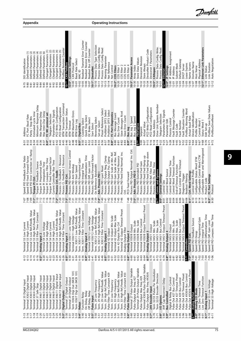
5-15
Term
inal
33
Dig
ital I
nput
5-16
Term
inal
X30
/2 D
igita
l Inp
ut5-
17Te
rmin
al X
30/3
Dig
ital I
nput
5-18
Term
inal
X30
/4 D
igita
l Inp
ut5-
19Te
rmin
al 3
7 Sa
fe S
top
5-20
Term
inal
X46
/1 D
igita
l Inp
ut5-
21Te
rmin
al X
46/3
Dig
ital I
nput
5-22
Term
inal
X46
/5 D
igita
l Inp
ut5-
23Te
rmin
al X
46/7
Dig
ital I
nput
5-24
Term
inal
X46
/9 D
igita
l Inp
ut5-
25Te
rmin
al X
46/1
1 D
igita
l Inp
ut5-
26Te
rmin
al X
46/1
3 D
igita
l Inp
ut5-
3*D
igita
l Out
puts
5-30
Term
inal
27
Dig
ital O
utpu
t5-
31Te
rmin
al 2
9 D
igita
l Out
put
5-32
Term
X30
/6 D
igi O
ut (M
CB 1
01)
5-33
Term
X30
/7 D
igi O
ut (M
CB 1
01)
5-4*
Rela
ys5-
40Fu
nctio
n R
elay
5-41
On
Del
ay, R
elay
5-42
Off
Del
ay, R
elay
5-5*
Puls
e In
put
5-50
Term
. 29
Low
Fre
quen
cy5-
51Te
rm. 2
9 H
igh
Fre
quen
cy5-
52Te
rm. 2
9 Lo
w R
ef./F
eedb
. Val
ue5-
53Te
rm. 2
9 H
igh
Ref
./Fee
db. V
alue
5-54
Puls
e Fi
lter
Tim
e Co
nsta
nt #
295-
55Te
rm. 3
3 Lo
w F
requ
ency
5-56
Term
. 33
Hig
h F
requ
ency
5-57
Term
. 33
Low
Ref
./Fee
db. V
alue
5-58
Term
. 33
Hig
h R
ef./F
eedb
. Val
ue5-
59Pu
lse
Filte
r Ti
me
Cons
tant
#33
5-6*
Puls
e O
utpu
t5-
60Te
rmin
al 2
7 Pu
lse
Out
put
Varia
ble
5-62
Puls
e O
utpu
t M
ax F
req
#27
5-63
Term
inal
29
Puls
e O
utpu
t Va
riabl
e5-
65Pu
lse
Out
put
Max
Fre
q #
295-
66Te
rmin
al X
30/6
Pul
se O
utpu
t Va
riabl
e5-
68Pu
lse
Out
put
Max
Fre
q #
X30/
65-
7*24
V E
ncod
er In
put
5-70
Term
32/
33 P
ulse
s Pe
r Re
volu
tion
5-71
Term
32/
33 E
ncod
er D
irect
ion
5-8*
I/O O
ptio
ns5-
80A
HF
Cap
Rec
onne
ct D
elay
5-9*
Bus
Cont
rolle
d5-
90D
igita
l & R
elay
Bus
Con
trol
5-93
Puls
e O
ut #
27 B
us C
ontr
ol5-
94Pu
lse
Out
#27
Tim
eout
Pre
set
5-95
Puls
e O
ut #
29 B
us C
ontr
ol5-
96Pu
lse
Out
#29
Tim
eout
Pre
set
5-97
Puls
e O
ut #
X30/
6 Bu
s Co
ntro
l5-
98Pu
lse
Out
#X3
0/6
Tim
eout
Pre
set
6-**
Ana
log
In/O
ut6-
0*A
nalo
g I/
O M
ode
6-00
Live
Zer
o T
imeo
ut T
ime
6-01
Live
Zer
o T
imeo
ut F
unct
ion
6-1*
Ana
log
Inpu
t 1
6-10
Term
inal
53
Low
Vol
tage
6-11
Term
inal
53
Hig
h V
olta
ge
6-12
Term
inal
53
Low
Cur
rent
6-13
Term
inal
53
Hig
h C
urre
nt6-
14Te
rmin
al 5
3 Lo
w R
ef./F
eedb
. Val
ue6-
15Te
rmin
al 5
3 H
igh
Ref
./Fee
db. V
alue
6-16
Term
inal
53
Filte
r Ti
me
Cons
tant
6-2*
Ana
log
Inpu
t 2
6-20
Term
inal
54
Low
Vol
tage
6-21
Term
inal
54
Hig
h V
olta
ge6-
22Te
rmin
al 5
4 Lo
w C
urre
nt6-
23Te
rmin
al 5
4 H
igh
Cur
rent
6-24
Term
inal
54
Low
Ref
./Fee
db. V
alue
6-25
Term
inal
54
Hig
h R
ef./F
eedb
. Val
ue6-
26Te
rmin
al 5
4 Fi
lter
Tim
e Co
nsta
nt6-
3*A
nalo
g In
put
36-
30Te
rmin
al X
30/1
1 Lo
w V
olta
ge6-
31Te
rmin
al X
30/1
1 H
igh
Vol
tage
6-34
Term
. X30
/11
Low
Ref
./Fee
db. V
alue
6-35
Term
. X30
/11
Hig
h R
ef./F
eedb
. Val
ue6-
36Te
rm. X
30/1
1 Fi
lter
Tim
e Co
nsta
nt6-
4*A
nalo
g In
put
46-
40Te
rmin
al X
30/1
2 Lo
w V
olta
ge6-
41Te
rmin
al X
30/1
2 H
igh
Vol
tage
6-44
Term
. X30
/12
Low
Ref
./Fee
db. V
alue
6-45
Term
. X30
/12
Hig
h R
ef./F
eedb
. Val
ue6-
46Te
rm. X
30/1
2 Fi
lter
Tim
e Co
nsta
nt6-
5*A
nalo
g O
utpu
t 1
6-50
Term
inal
42
Out
put
6-51
Term
inal
42
Out
put
Min
Sca
le6-
52Te
rmin
al 4
2 O
utpu
t M
ax S
cale
6-53
Term
42
Out
put
Bus
Ctrl
6-54
Term
inal
42
Out
put
Tim
eout
Pre
set
6-55
Ana
log
Out
put
Filte
r6-
6*A
nalo
g O
utpu
t 2
6-60
Term
inal
X30
/8 O
utpu
t6-
61Te
rmin
al X
30/8
Min
. Sca
le6-
62Te
rmin
al X
30/8
Max
. Sca
le6-
63Te
rmin
al X
30/8
Bus
Con
trol
6-64
Term
inal
X30
/8 O
utpu
t Ti
meo
ut P
rese
t6-
7*A
nalo
g O
utpu
t 3
6-70
Term
inal
X45
/1 O
utpu
t6-
71Te
rmin
al X
45/1
Min
. Sca
le6-
72Te
rmin
al X
45/1
Max
. Sca
le6-
73Te
rmin
al X
45/1
Bus
Con
trol
6-74
Term
inal
X45
/1 O
utpu
t Ti
meo
ut P
rese
t6-
8*A
nalo
g O
utpu
t 4
6-80
Term
inal
X45
/3 O
utpu
t6-
81Te
rmin
al X
45/3
Min
. Sca
le6-
82Te
rmin
al X
45/3
Max
. Sca
le6-
83Te
rmin
al X
45/3
Bus
Con
trol
6-84
Term
inal
X45
/3 O
utpu
t Ti
meo
ut P
rese
t7-
**Co
ntro
llers
7-0*
Spee
d P
ID C
trl.
7-00
Spee
d P
ID F
eedb
ack
Sour
ce7-
01Sp
eed
PID
Dro
op7-
02Sp
eed
PID
Pro
port
iona
l Gai
n7-
03Sp
eed
PID
Inte
gral
Tim
e7-
04Sp
eed
PID
Diff
eren
tiatio
n T
ime
7-05
Spee
d P
ID D
iff. G
ain
Lim
it7-
06Sp
eed
PID
Low
pass
Filt
er T
ime
7-07
Spee
d P
ID F
eedb
ack
Gea
r Ra
tio7-
08Sp
eed
PID
Fee
d F
orw
ard
Fac
tor
7-09
Spee
d P
ID E
rror
Cor
rect
ion
w/
Ram
p7-
1*To
rque
PI
Ctrl.
7-10
Torq
ue P
I Fee
dbac
k So
urce
7-12
Torq
ue P
I Pro
port
iona
l Gai
n7-
13To
rque
PI I
nteg
ratio
n T
ime
7-16
Torq
ue P
I Low
pass
Filt
er T
ime
7-18
Torq
ue P
I Fee
d F
orw
ard
Fac
tor
7-19
Curr
ent
Cont
rolle
r Ri
se T
ime
7-2*
Proc
ess
Ctrl.
Fee
db7-
20Pr
oces
s CL
Fee
dbac
k 1
Reso
urce
7-22
Proc
ess
CL F
eedb
ack
2 Re
sour
ce7-
3*Pr
oces
s PI
D C
trl.
7-30
Proc
ess
PID
Nor
mal
/ In
vers
e Co
ntro
l7-
31Pr
oces
s PI
D A
nti W
indu
p7-
32Pr
oces
s PI
D S
tart
Spe
ed7-
33Pr
oces
s PI
D P
ropo
rtio
nal G
ain
7-34
Proc
ess
PID
Inte
gral
Tim
e7-
35Pr
oces
s PI
D D
iffer
entia
tion
Tim
e7-
36Pr
oces
s PI
D D
iff. G
ain
Lim
it7-
38Pr
oces
s PI
D F
eed
For
war
d F
acto
r7-
39O
n R
efer
ence
Ban
dwid
th7-
4*A
dv. P
roce
ss P
ID I
7-40
Proc
ess
PID
I-pa
rt R
eset
7-41
Proc
ess
PID
Out
put
Neg
. Cla
mp
7-42
Proc
ess
PID
Out
put
Pos.
Cla
mp
7-43
Proc
ess
PID
Gai
n S
cale
at
Min
. Ref
.7-
44Pr
oces
s PI
D G
ain
Sca
le a
t M
ax. R
ef.
7-45
Proc
ess
PID
Fee
d F
wd
Res
ourc
e7-
46Pr
oces
s PI
D F
eed
Fw
d N
orm
al/
Inv.
Ctrl.
7-48
PCD
Fee
d F
orw
ard
7-49
Proc
ess
PID
Out
put
Nor
mal
/ In
v. C
trl.
7-5*
Adv
. Pro
cess
PID
II7-
50Pr
oces
s PI
D E
xten
ded
PID
7-51
Proc
ess
PID
Fee
d F
wd
Gai
n7-
52Pr
oces
s PI
D F
eed
Fw
d R
amp
up
7-53
Proc
ess
PID
Fee
d F
wd
Ram
p d
own
7-56
Proc
ess
PID
Ref
. Filt
er T
ime
7-57
Proc
ess
PID
Fb.
Filt
er T
ime
8-**
Com
m. a
nd O
ptio
ns8-
0*G
ener
al S
ettin
gs8-
01Co
ntro
l Site
8-02
Cont
rol W
ord
Sou
rce
8-03
Cont
rol W
ord
Tim
eout
Tim
e8-
04Co
ntro
l Wor
d T
imeo
ut F
unct
ion
8-05
End-
of-T
imeo
ut F
unct
ion
8-06
Rese
t Co
ntro
l Wor
d T
imeo
ut8-
07D
iagn
osis
Trig
ger
8-08
Read
out
Filte
ring
8-1*
Ctrl.
Wor
d S
ettin
gs8-
10Co
ntro
l Wor
d P
rofil
e8-
13Co
nfigu
rabl
e St
atus
Wor
d S
TW8-
14Co
nfigu
rabl
e Co
ntro
l Wor
d C
TW8-
17Co
nfigu
rabl
e A
larm
and
War
ning
wor
d8-
19Pr
oduc
t Co
de8-
3*FC
Por
t Se
ttin
gs8-
30Pr
otoc
ol
8-31
Addr
ess
8-32
FC P
ort
Baud
Rat
e8-
33Pa
rity
/ St
op B
its8-
34Es
timat
ed c
ycle
tim
e8-
35M
inim
um R
espo
nse
Del
ay8-
36M
ax R
espo
nse
Del
ay8-
37M
ax In
ter-
Char
Del
ay8-
4*FC
MC
pro
toco
l set
8-40
Tele
gram
Sel
ectio
n8-
41Pa
ram
eter
s fo
r Si
gnal
s8-
42PC
D W
rite
Confi
gura
tion
8-43
PCD
Rea
d C
onfig
urat
ion
8-45
BTM
Tra
nsac
tion
Com
man
d8-
46BT
M T
rans
actio
n S
tatu
s8-
47BT
M T
imeo
ut8-
48BT
M M
axim
um E
rror
s8-
49BT
M E
rror
Log
8-5*
Dig
ital/B
us8-
50Co
astin
g S
elec
t8-
51Q
uick
Sto
p S
elec
t8-
52D
C B
rake
Sel
ect
8-53
Star
t Se
lect
8-54
Reve
rsin
g S
elec
t8-
55Se
t-up
Sel
ect
8-56
Pres
et R
efer
ence
Sel
ect
8-57
Profi
driv
e O
FF2
Sele
ct8-
58Pr
ofidr
ive
OFF
3 Se
lect
8-8*
FC P
ort
Dia
gnos
tics
8-80
Bus
Mes
sage
Cou
nt8-
81Bu
s Er
ror
Coun
t8-
82Sl
ave
Mes
sage
s Rc
vd8-
83Sl
ave
Erro
r Co
unt
8-9*
Bus
Jog
8-90
Bus
Jog
1 S
peed
8-91
Bus
Jog
2 S
peed
9-**
PRO
FIdr
ive
9-00
Setp
oint
9-07
Actu
al V
alue
9-15
PCD
Writ
e Co
nfigu
ratio
n9-
16PC
D R
ead
Con
figur
atio
n9-
18N
ode
Addr
ess
9-19
Driv
e U
nit
Syst
em N
umbe
r9-
22Te
legr
am S
elec
tion
9-23
Para
met
ers
for
Sign
als
9-27
Para
met
er E
dit
9-28
Proc
ess
Cont
rol
9-44
Faul
t M
essa
ge C
ount
er9-
45Fa
ult
Code
9-47
Faul
t N
umbe
r9-
52Fa
ult
Situ
atio
n C
ount
er9-
53Pr
ofibu
s W
arni
ng W
ord
9-63
Actu
al B
aud
Rat
e9-
64D
evic
e Id
entifi
catio
n9-
65Pr
ofile
Num
ber
9-67
Cont
rol W
ord
19-
68St
atus
Wor
d 1
9-70
Edit
Set
-up
9-71
Profi
bus
Save
Dat
a Va
lues
9-72
Profi
busD
riveR
eset
9-75
DO
Iden
tifica
tion
9-80
Defi
ned
Par
amet
ers
(1)
9-81
Defi
ned
Par
amet
ers
(2)
9-82
Defi
ned
Par
amet
ers
(3)
9-83
Defi
ned
Par
amet
ers
(4)
9-84
Defi
ned
Par
amet
ers
(5)
9-85
Defi
ned
Par
amet
ers
(6)
9-90
Chan
ged
Par
amet
ers
(1)
9-91
Chan
ged
Par
amet
ers
(2)
9-92
Chan
ged
Par
amet
ers
(3)
9-93
Chan
ged
Par
amet
ers
(4)
9-94
Chan
ged
Par
amet
ers
(5)
9-99
Profi
bus
Revi
sion
Cou
nter
10-*
*CA
N F
ield
bus
10-0
*Co
mm
on S
ettin
gs10
-00
CAN
Pro
toco
l10
-01
Baud
Rat
e Se
lect
10-0
2M
AC ID
10-0
5Re
adou
t Tr
ansm
it E
rror
Cou
nter
10-0
6Re
adou
t Re
ceiv
e Er
ror
Coun
ter
10-0
7Re
adou
t Bu
s O
ff C
ount
er10
-1*
Dev
iceN
et10
-10
Proc
ess
Dat
a Ty
pe S
elec
tion
10-1
1Pr
oces
s D
ata
Confi
g W
rite
10-1
2Pr
oces
s D
ata
Confi
g R
ead
10-1
3W
arni
ng P
aram
eter
10-1
4N
et R
efer
ence
10-1
5N
et C
ontr
ol10
-2*
COS
Filte
rs10
-20
COS
Filte
r 1
10-2
1CO
S Fi
lter
210
-22
COS
Filte
r 3
10-2
3CO
S Fi
lter
410
-3*
Para
met
er A
cces
s10
-30
Arr
ay In
dex
10-3
1St
ore
Dat
a Va
lues
10-3
2D
evic
enet
Rev
isio
n10
-33
Stor
e A
lway
s10
-34
Dev
iceN
et P
rodu
ct C
ode
10-3
9D
evic
enet
F P
aram
eter
s10
-5*
CAN
open
10-5
0Pr
oces
s D
ata
Confi
g W
rite.
10-5
1Pr
oces
s D
ata
Confi
g R
ead.
12-*
*Et
hern
et12
-0*
IP S
ettin
gs12
-00
IP A
ddre
ss A
ssig
nmen
t12
-01
IP A
ddre
ss12
-02
Subn
et M
ask
12-0
3D
efau
lt G
atew
ay12
-04
DH
CP S
erve
r12
-05
Leas
e Ex
pire
s12
-06
Nam
e Se
rver
s12
-07
Dom
ain
Nam
e12
-08
Hos
t N
ame
12-0
9Ph
ysic
al A
ddre
ss12
-1*
Ethe
rnet
Lin
k Pa
ram
eter
s12
-10
Link
Sta
tus
12-1
1Li
nk D
urat
ion
12-1
2Au
to N
egot
iatio
n
Appendix Operating Instructions
MG33AQ02 Danfoss A/S © 07/2015 All rights reserved. 75
9 9
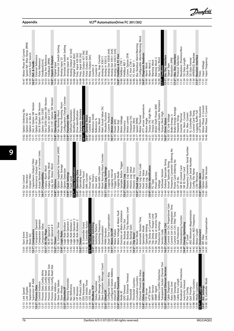
12-1
3Li
nk S
peed
12-1
4Li
nk D
uple
x12
-18
Supe
rvis
or M
AC12
-19
Supe
rvis
or IP
Add
r.12
-2*
Proc
ess
Dat
a12
-20
Cont
rol I
nsta
nce
12-2
1Pr
oces
s D
ata
Confi
g W
rite
12-2
2Pr
oces
s D
ata
Confi
g R
ead
12-2
3Pr
oces
s D
ata
Confi
g W
rite
Size
12-2
4Pr
oces
s D
ata
Confi
g R
ead
Siz
e12
-27
Mas
ter
Addr
ess
12-2
8St
ore
Dat
a Va
lues
12-2
9St
ore
Alw
ays
12-3
*Et
herN
et/IP
12-3
0W
arni
ng P
aram
eter
12-3
1N
et R
efer
ence
12-3
2N
et C
ontr
ol12
-33
CIP
Rev
isio
n12
-34
CIP
Pro
duct
Cod
e12
-35
EDS
Para
met
er12
-37
COS
Inhi
bit
Tim
er12
-38
COS
Filte
r12
-4*
Mod
bus
TCP
12-4
0St
atus
Par
amet
er12
-41
Slav
e M
essa
ge C
ount
12-4
2Sl
ave
Exce
ptio
n M
essa
ge C
ount
12-5
*Et
herC
AT12
-50
Confi
gure
d S
tatio
n A
lias
12-5
1Co
nfigu
red
Sta
tion
Add
ress
12-5
9Et
herC
AT S
tatu
s12
-6*
Ethe
rnet
Pow
erLi
nk12
-60
Nod
e ID
12-6
2SD
O T
imeo
ut12
-63
Basi
c Et
hern
et T
imeo
ut12
-66
Thre
shol
d12
-67
Thre
shol
d C
ount
ers
12-6
8Cu
mul
ativ
e Co
unte
rs12
-69
Ethe
rnet
Pow
erLi
nk S
tatu
s12
-8*
Oth
er E
ther
net
Serv
ices
12-8
0FT
P S
erve
r12
-81
HTT
P S
erve
r12
-82
SMTP
Ser
vice
12-8
3SN
MP
Age
nt12
-84
Addr
ess
Confl
ict
Det
ectio
n12
-89
Tran
spar
ent
Sock
et C
hann
el P
ort
12-9
*A
dvan
ced
Eth
erne
t Se
rvic
es12
-90
Cabl
e D
iagn
ostic
12-9
1Au
to C
ross
Ove
r12
-92
IGM
P S
noop
ing
12-9
3Ca
ble
Erro
r Le
ngth
12-9
4Br
oadc
ast
Stor
m P
rote
ctio
n12
-95
Inac
tivity
tim
eout
12-9
6Po
rt C
onfig
12-9
7Q
oS P
riorit
y12
-98
Inte
rfac
e Co
unte
rs12
-99
Med
ia C
ount
ers
13-*
*Sm
art
Logi
c13
-0*
SLC
Set
tings
13-0
0SL
Con
trol
ler
Mod
e
13-0
1St
art
Even
t13
-02
Stop
Eve
nt13
-03
Rese
t SL
C13
-1*
Com
para
tors
13-1
0Co
mpa
rato
r O
pera
nd13
-11
Com
para
tor
Ope
rato
r13
-12
Com
para
tor
Valu
e13
-1*
RS F
lip F
lops
13-1
5RS
-FF
Ope
rand
S13
-16
RS-F
F O
pera
nd R
13-2
*Ti
mer
s13
-20
SL C
ontr
olle
r Ti
mer
13-4
*Lo
gic
Rule
s13
-40
Logi
c Ru
le B
oole
an 1
13-4
1Lo
gic
Rule
Ope
rato
r 1
13-4
2Lo
gic
Rule
Boo
lean
213
-43
Logi
c Ru
le O
pera
tor
213
-44
Logi
c Ru
le B
oole
an 3
13-5
*St
ates
13-5
1SL
Con
trol
ler
Even
t13
-52
SL C
ontr
olle
r Ac
tion
14-*
*Sp
ecia
l Fun
ctio
ns14
-0*
Inve
rter
Sw
itchi
ng14
-00
Switc
hing
Pat
tern
14-0
1Sw
itchi
ng F
requ
ency
14-0
3O
verm
odul
atio
n14
-04
PWM
Ran
dom
14-0
6D
ead
Tim
e Co
mpe
nsat
ion
14-1
*M
ains
On/
Off
14-1
0M
ains
Fai
lure
14-1
1M
ains
Vol
tage
at
Mai
ns F
ault
14-1
2Fu
nctio
n a
t M
ains
Imba
lanc
e14
-14
Kin.
Bac
kup
Tim
e O
ut14
-15
Kin.
Bac
kup
Trip
Rec
over
y Le
vel
14-1
6Ki
n. B
acku
p G
ain
14-2
*Tr
ip R
eset
14-2
0Re
set
Mod
e14
-21
Auto
mat
ic R
esta
rt T
ime
14-2
2O
pera
tion
Mod
e14
-23
Type
code
Set
ting
14-2
4Tr
ip D
elay
at
Curr
ent
Lim
it14
-25
Trip
Del
ay a
t To
rque
Lim
it14
-26
Trip
Del
ay a
t In
vert
er F
ault
14-2
8Pr
oduc
tion
Set
tings
14-2
9Se
rvic
e Co
de14
-3*
Curr
ent
Lim
it C
trl.
14-3
0Cu
rren
t Li
m C
trl,
Prop
ortio
nal G
ain
14-3
1Cu
rren
t Li
m C
trl,
Inte
grat
ion
Tim
e14
-32
Curr
ent
Lim
Ctr
l, Fi
lter
Tim
e14
-35
Stal
l Pro
tect
ion
14-3
6Fi
eldw
eake
ning
Fun
ctio
n14
-4*
Ener
gy O
ptim
isin
g14
-40
VT L
evel
14-4
1A
EO M
inim
um M
agne
tisat
ion
14-4
2M
inim
um A
EO F
requ
ency
14-4
3M
otor
Cos
phi
14-5
*En
viro
nmen
t14
-50
RFI F
ilter
14-5
1D
C L
ink
Com
pens
atio
n
14-5
2Fa
n C
ontr
ol14
-53
Fan
Mon
itor
14-5
5O
utpu
t Fi
lter
14-5
6Ca
paci
tanc
e O
utpu
t Fi
lter
14-5
7In
duct
ance
Out
put
Filte
r14
-59
Actu
al N
umbe
r of
Inve
rter
Uni
ts14
-7*
Com
patib
ility
14-7
2Le
gacy
Ala
rm W
ord
14-7
3Le
gacy
War
ning
Wor
d14
-74
Leg.
Ext
. Sta
tus
Wor
d14
-8*
Opt
ions
14-8
0O
ptio
n S
uppl
ied
by
Exte
rnal
24V
DC
14-8
8O
ptio
n D
ata
Stor
age
14-8
9O
ptio
n D
etec
tion
14-9
*Fa
ult
Sett
ings
14-9
0Fa
ult
Leve
l15
-**
Dri
ve In
form
atio
n15
-0*
Ope
ratin
g D
ata
15-0
0O
pera
ting
hou
rs15
-01
Runn
ing
Hou
rs15
-02
kWh
Cou
nter
15-0
3Po
wer
Up'
s15
-04
Ove
r Te
mp'
s15
-05
Ove
r Vo
lt's
15-0
6Re
set
kWh
Cou
nter
15-0
7Re
set
Runn
ing
Hou
rs C
ount
er15
-1*
Dat
a Lo
g S
ettin
gs15
-10
Logg
ing
Sou
rce
15-1
1Lo
ggin
g In
terv
al15
-12
Trig
ger
Even
t15
-13
Logg
ing
Mod
e15
-14
Sam
ples
Bef
ore
Trig
ger
15-2
*H
isto
ric
Log
15-2
0H
isto
ric L
og: E
vent
15-2
1H
isto
ric L
og: V
alue
15-2
2H
isto
ric L
og: T
ime
15-3
*Fa
ult
Log
15-3
0Fa
ult
Log:
Err
or C
ode
15-3
1Fa
ult
Log:
Val
ue15
-32
Faul
t Lo
g: T
ime
15-4
*D
rive
Iden
tifica
tion
15-4
0FC
Typ
e15
-41
Pow
er S
ectio
n15
-42
Volta
ge15
-43
Soft
war
e Ve
rsio
n15
-44
Ord
ered
Typ
ecod
e St
ring
15-4
5Ac
tual
Typ
ecod
e St
ring
15-4
6Fr
eque
ncy
Conv
erte
r O
rder
ing
No
15-4
7Po
wer
Car
d O
rder
ing
No
15-4
8LC
P Id
No
15-4
9SW
ID C
ontr
ol C
ard
15-5
0SW
ID P
ower
Car
d15
-51
Freq
uenc
y Co
nver
ter
Seria
l Num
ber
15-5
3Po
wer
Car
d S
eria
l Num
ber
15-5
4Co
nfig
File
Nam
e15
-59
CSIV
File
nam
e15
-6*
Opt
ion
Iden
t15
-60
Opt
ion
Mou
nted
15-6
1O
ptio
n S
W V
ersi
on
15-6
2O
ptio
n O
rder
ing
No
15-6
3O
ptio
n S
eria
l No
15-7
0O
ptio
n in
Slo
t A
15-7
1Sl
ot A
Opt
ion
SW
Ver
sion
15-7
2O
ptio
n in
Slo
t B
15-7
3Sl
ot B
Opt
ion
SW
Ver
sion
15-7
4O
ptio
n in
Slo
t C0
/E0
15-7
5Sl
ot C
0/E0
Opt
ion
SW
Ver
sion
15-7
6O
ptio
n in
Slo
t C1
/E1
15-7
7Sl
ot C
1/E1
Opt
ion
SW
Ver
sion
15-8
*O
pera
ting
Dat
a II
15-8
0Fa
n R
unni
ng H
ours
15-8
1Pr
eset
Fan
Run
ning
Hou
rs15
-89
Confi
gura
tion
Cha
nge
Coun
ter
15-9
*Pa
ram
eter
Info
15-9
2D
efine
d P
aram
eter
s15
-93
Mod
ified
Par
amet
ers
15-9
8D
rive
Iden
tifica
tion
15-9
9Pa
ram
eter
Met
adat
a16
-**
Dat
a Re
adou
ts16
-0*
Gen
eral
Sta
tus
16-0
0Co
ntro
l Wor
d16
-01
Refe
renc
e [U
nit]
16-0
2Re
fere
nce
%16
-03
Stat
us W
ord
16-0
5M
ain
Act
ual V
alue
[%]
16-0
6A
bsol
ute
Posi
tion
16-0
9Cu
stom
Rea
dout
16-1
*M
otor
Sta
tus
16-1
0Po
wer
[kW
]16
-11
Pow
er [h
p]16
-12
Mot
or V
olta
ge16
-13
Freq
uenc
y16
-14
Mot
or c
urre
nt16
-15
Freq
uenc
y [%
]16
-16
Torq
ue [N
m]
16-1
7Sp
eed
[RPM
]16
-18
Mot
or T
herm
al16
-19
KTY
sen
sor
tem
pera
ture
16-2
0M
otor
Ang
le16
-21
Torq
ue [%
] H
igh
Res
.16
-22
Torq
ue [%
]16
-23
Mot
or S
haft
Pow
er [k
W]
16-2
4Ca
libra
ted
Sta
tor
Resi
stan
ce16
-25
Torq
ue [N
m]
Hig
h16
-3*
Dri
ve S
tatu
s16
-30
DC
Lin
k Vo
ltage
16-3
2Br
ake
Ener
gy /
s16
-33
Brak
e En
ergy
Ave
rage
16-3
4H
eats
ink
Tem
p.16
-35
Inve
rter
The
rmal
16-3
6In
v. N
om. C
urre
nt16
-37
Inv.
Max
. Cur
rent
16-3
8SL
Con
trol
ler
Stat
e16
-39
Cont
rol C
ard
Tem
p.16
-40
Logg
ing
Buff
er F
ull
16-4
1LC
P B
otto
m S
tatu
slin
e16
-45
Mot
or P
hase
U C
urre
nt16
-46
Mot
or P
hase
V C
urre
nt
16-4
7M
otor
Pha
se W
Cur
rent
16-4
8Sp
eed
Ref
. Aft
er R
amp
[RPM
]16
-49
Curr
ent
Faul
t So
urce
16-5
*Re
f. &
Fee
db.
16-5
0Ex
tern
al R
efer
ence
16-5
1Pu
lse
Refe
renc
e16
-52
Feed
back
[Uni
t]16
-53
Dig
i Pot
Ref
eren
ce16
-57
Feed
back
[RPM
]16
-6*
Inpu
ts &
Out
puts
16-6
0D
igita
l Inp
ut16
-61
Term
inal
53
Switc
h S
ettin
g16
-62
Ana
log
Inpu
t 53
16-6
3Te
rmin
al 5
4 Sw
itch
Set
ting
16-6
4A
nalo
g In
put
5416
-65
Ana
log
Out
put
42 [m
A]
16-6
6D
igita
l Out
put
[bin
]16
-67
Freq
. Inp
ut #
29 [H
z]16
-68
Freq
. Inp
ut #
33 [H
z]16
-69
Puls
e O
utpu
t #2
7 [H
z]16
-70
Puls
e O
utpu
t #2
9 [H
z]16
-71
Rela
y O
utpu
t [b
in]
16-7
2Co
unte
r A
16-7
3Co
unte
r B
16-7
4Pr
ec. S
top
Cou
nter
16-7
5A
nalo
g In
X30
/11
16-7
6A
nalo
g In
X30
/12
16-7
7A
nalo
g O
ut X
30/8
[mA
]16
-78
Ana
log
Out
X45
/1 [m
A]
16-7
9A
nalo
g O
ut X
45/3
[mA
]16
-8*
Fiel
dbus
& F
C P
ort
16-8
0Fi
eldb
us C
TW 1
16-8
2Fi
eldb
us R
EF 1
16-8
4Co
mm
. Opt
ion
STW
16-8
5FC
Por
t C
TW 1
16-8
6FC
Por
t RE
F 1
16-8
7Bu
s Re
adou
t A
larm
/War
ning
16-8
9Co
nfigu
rabl
e A
larm
/War
ning
Wor
d16
-9*
Dia
gnos
is R
eado
uts
16-9
0A
larm
Wor
d16
-91
Ala
rm W
ord
216
-92
War
ning
Wor
d16
-93
War
ning
Wor
d 2
16-9
4Ex
t. S
tatu
s W
ord
17-*
*Fe
edba
ck17
-1*
Inc.
Enc
. Int
erfa
ce17
-10
Sign
al T
ype
17-1
1Re
solu
tion
(PPR
)17
-2*
Abs
. Enc
. Int
erfa
ce17
-20
Prot
ocol
Sel
ectio
n17
-21
Reso
lutio
n (P
ositi
ons/
Rev)
17-2
4SS
I Dat
a Le
ngth
17-2
5Cl
ock
Rate
17-2
6SS
I Dat
a Fo
rmat
17-3
4H
IPER
FACE
Bau
drat
e17
-5*
Reso
lver
Inte
rfac
e17
-50
Pole
s17
-51
Inpu
t Vo
ltage
17-5
2In
put
Freq
uenc
y
Appendix VLT® AutomationDrive FC 301/302
76 Danfoss A/S © 07/2015 All rights reserved. MG33AQ02
99
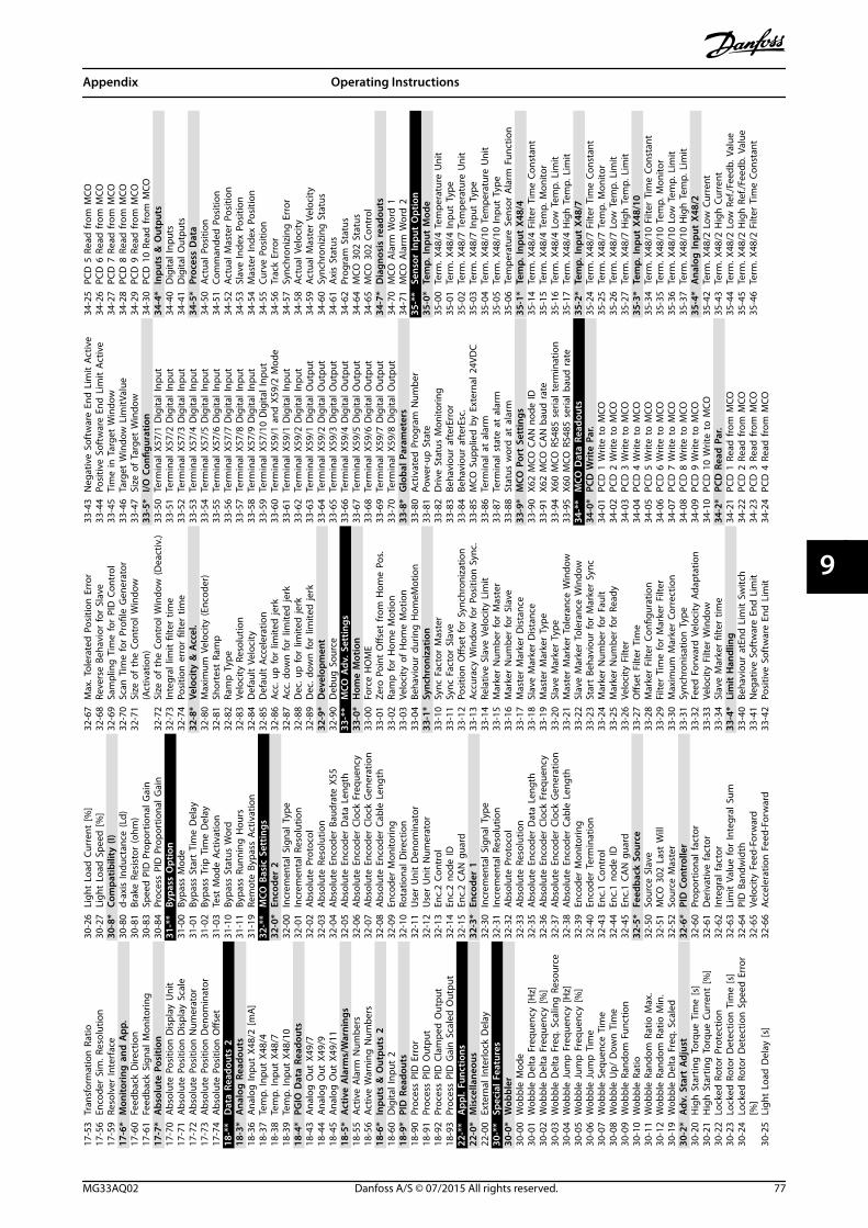
17-5
3Tr
ansf
orm
atio
n R
atio
17-5
6En
code
r Si
m. R
esol
utio
n17
-59
Reso
lver
Inte
rfac
e17
-6*
Mon
itori
ng a
nd A
pp.
17-6
0Fe
edba
ck D
irect
ion
17-6
1Fe
edba
ck S
igna
l Mon
itorin
g17
-7*
Abs
olut
e Po
sitio
n17
-70
Abs
olut
e Po
sitio
n D
ispl
ay U
nit
17-7
1A
bsol
ute
Posi
tion
Dis
play
Sca
le17
-72
Abs
olut
e Po
sitio
n N
umer
ator
17-7
3A
bsol
ute
Posi
tion
Den
omin
ator
17-7
4A
bsol
ute
Posi
tion
Offs
et18
-**
Dat
a Re
adou
ts 2
18-3
*A
nalo
g R
eado
uts
18-3
6A
nalo
g In
put
X48/
2 [m
A]
18-3
7Te
mp.
Inpu
t X4
8/4
18-3
8Te
mp.
Inpu
t X4
8/7
18-3
9Te
mp.
Inpu
t X4
8/10
18-4
*PG
IO D
ata
Read
outs
18-4
3A
nalo
g O
ut X
49/7
18-4
4A
nalo
g O
ut X
49/9
18-4
5A
nalo
g O
ut X
49/1
118
-5*
Act
ive
Ala
rms/
War
ning
s18
-55
Activ
e A
larm
Num
bers
18-5
6Ac
tive
War
ning
Num
bers
18-6
*In
puts
& O
utpu
ts 2
18-6
0D
igita
l Inp
ut 2
18-9
*PI
D R
eado
uts
18-9
0Pr
oces
s PI
D E
rror
18-9
1Pr
oces
s PI
D O
utpu
t18
-92
Proc
ess
PID
Cla
mpe
d O
utpu
t18
-93
Proc
ess
PID
Gai
n S
cale
d O
utpu
t22
-**
App
l. Fu
nctio
ns22
-0*
Mis
cella
neou
s22
-00
Exte
rnal
Inte
rlock
Del
ay30
-**
Spec
ial F
eatu
res
30-0
*W
obbl
er30
-00
Wob
ble
Mod
e30
-01
Wob
ble
Del
ta F
requ
ency
[Hz]
30-0
2W
obbl
e D
elta
Fre
quen
cy [%
]30
-03
Wob
ble
Del
ta F
req.
Sca
ling
Res
ourc
e30
-04
Wob
ble
Jum
p F
requ
ency
[Hz]
30-0
5W
obbl
e Ju
mp
Fre
quen
cy [%
]30
-06
Wob
ble
Jum
p T
ime
30-0
7W
obbl
e Se
quen
ce T
ime
30-0
8W
obbl
e U
p/ D
own
Tim
e30
-09
Wob
ble
Rand
om F
unct
ion
30-1
0W
obbl
e Ra
tio30
-11
Wob
ble
Rand
om R
atio
Max
.30
-12
Wob
ble
Rand
om R
atio
Min
.30
-19
Wob
ble
Del
ta F
req.
Sca
led
30-2
*A
dv. S
tart
Adj
ust
30-2
0H
igh
Sta
rtin
g T
orqu
e Ti
me
[s]
30-2
1H
igh
Sta
rtin
g T
orqu
e Cu
rren
t [%
]30
-22
Lock
ed R
otor
Pro
tect
ion
30-2
3Lo
cked
Rot
or D
etec
tion
Tim
e [s
]30
-24
Lock
ed R
otor
Det
ectio
n S
peed
Err
or[%
]30
-25
Ligh
t Lo
ad D
elay
[s]
30-2
6Li
ght
Load
Cur
rent
[%]
30-2
7Li
ght
Load
Spe
ed [%
]30
-8*
Com
patib
ility
(I)
30-8
0d-
axis
Indu
ctan
ce (L
d)30
-81
Brak
e Re
sist
or (o
hm)
30-8
3Sp
eed
PID
Pro
port
iona
l Gai
n30
-84
Proc
ess
PID
Pro
port
iona
l Gai
n31
-**
Bypa
ss O
ptio
n31
-00
Bypa
ss M
ode
31-0
1By
pass
Sta
rt T
ime
Del
ay31
-02
Bypa
ss T
rip T
ime
Del
ay31
-03
Test
Mod
e Ac
tivat
ion
31-1
0By
pass
Sta
tus
Wor
d31
-11
Bypa
ss R
unni
ng H
ours
31-1
9Re
mot
e By
pass
Act
ivat
ion
32-*
*M
CO B
asic
Set
tings
32-0
*En
code
r 2
32-0
0In
crem
enta
l Sig
nal T
ype
32-0
1In
crem
enta
l Res
olut
ion
32-0
2A
bsol
ute
Prot
ocol
32-0
3A
bsol
ute
Reso
lutio
n32
-04
Abs
olut
e En
code
r Ba
udra
te X
5532
-05
Abs
olut
e En
code
r D
ata
Leng
th32
-06
Abs
olut
e En
code
r Cl
ock
Freq
uenc
y32
-07
Abs
olut
e En
code
r Cl
ock
Gen
erat
ion
32-0
8A
bsol
ute
Enco
der
Cabl
e Le
ngth
32-0
9En
code
r M
onito
ring
32-1
0Ro
tatio
nal D
irect
ion
32-1
1U
ser
Uni
t D
enom
inat
or32
-12
Use
r U
nit
Num
erat
or32
-13
Enc.
2 Co
ntro
l32
-14
Enc.
2 no
de ID
32-1
5En
c.2
CAN
gua
rd32
-3*
Enco
der
132
-30
Incr
emen
tal S
igna
l Typ
e32
-31
Incr
emen
tal R
esol
utio
n32
-32
Abs
olut
e Pr
otoc
ol32
-33
Abs
olut
e Re
solu
tion
32-3
5A
bsol
ute
Enco
der
Dat
a Le
ngth
32-3
6A
bsol
ute
Enco
der
Cloc
k Fr
eque
ncy
32-3
7A
bsol
ute
Enco
der
Cloc
k G
ener
atio
n32
-38
Abs
olut
e En
code
r Ca
ble
Leng
th32
-39
Enco
der
Mon
itorin
g32
-40
Enco
der
Term
inat
ion
32-4
3En
c.1
Cont
rol
32-4
4En
c.1
node
ID32
-45
Enc.
1 CA
N g
uard
32-5
*Fe
edba
ck S
ourc
e32
-50
Sour
ce S
lave
32-5
1M
CO 3
02 L
ast
Will
32-5
2So
urce
Mas
ter
32-6
*PI
D C
ontr
olle
r32
-60
Prop
ortio
nal f
acto
r32
-61
Der
ivat
ive
fact
or32
-62
Inte
gral
fact
or32
-63
Lim
it V
alue
for
Inte
gral
Sum
32-6
4PI
D B
andw
idth
32-6
5Ve
loci
ty F
eed-
Forw
ard
32-6
6Ac
cele
ratio
n F
eed-
Forw
ard
32-6
7M
ax. T
oler
ated
Pos
ition
Err
or32
-68
Reve
rse
Beha
vior
for
Slav
e32
-69
Sam
plin
g T
ime
for
PID
Con
trol
32-7
0Sc
an T
ime
for
Profi
le G
ener
ator
32-7
1Si
ze o
f th
e Co
ntro
l Win
dow
(Act
ivat
ion)
32-7
2Si
ze o
f th
e Co
ntro
l Win
dow
(Dea
ctiv
.)32
-73
Inte
gral
lim
it fi
lter
time
32-7
4Po
sitio
n e
rror
filte
r tim
e32
-8*
Velo
city
& A
ccel
.32
-80
Max
imum
Vel
ocity
(Enc
oder
)32
-81
Shor
test
Ram
p32
-82
Ram
p T
ype
32-8
3Ve
loci
ty R
esol
utio
n32
-84
Def
ault
Vel
ocity
32-8
5D
efau
lt A
ccel
erat
ion
32-8
6Ac
c. u
p fo
r lim
ited
jerk
32-8
7Ac
c. d
own
for
limite
d je
rk32
-88
Dec
. up
for
limite
d je
rk32
-89
Dec
. dow
n fo
r lim
ited
jerk
32-9
*D
evel
opm
ent
32-9
0D
ebug
Sou
rce
33-*
*M
CO A
dv. S
ettin
gs33
-0*
Hom
e M
otio
n33
-00
Forc
e H
OM
E33
-01
Zero
Poi
nt O
ffset
from
Hom
e Po
s.33
-02
Ram
p fo
r H
ome
Mot
ion
33-0
3Ve
loci
ty o
f H
ome
Mot
ion
33-0
4Be
havi
our
durin
g H
omeM
otio
n33
-1*
Sync
hron
izat
ion
33-1
0Sy
nc F
acto
r M
aste
r33
-11
Sync
Fac
tor
Slav
e33
-12
Posi
tion
Offs
et fo
r Sy
nchr
oniz
atio
n33
-13
Accu
racy
Win
dow
for
Posi
tion
Syn
c.33
-14
Rela
tive
Slav
e Ve
loci
ty L
imit
33-1
5M
arke
r N
umbe
r fo
r M
aste
r33
-16
Mar
ker
Num
ber
for
Slav
e33
-17
Mas
ter
Mar
ker
Dis
tanc
e33
-18
Slav
e M
arke
r D
ista
nce
33-1
9M
aste
r M
arke
r Ty
pe33
-20
Slav
e M
arke
r Ty
pe33
-21
Mas
ter
Mar
ker
Tole
ranc
e W
indo
w33
-22
Slav
e M
arke
r To
lera
nce
Win
dow
33-2
3St
art
Beha
viou
r fo
r M
arke
r Sy
nc33
-24
Mar
ker
Num
ber
for
Faul
t33
-25
Mar
ker
Num
ber
for
Read
y33
-26
Velo
city
Filt
er33
-27
Offs
et F
ilter
Tim
e33
-28
Mar
ker
Filte
r Co
nfigu
ratio
n33
-29
Filte
r Ti
me
for
Mar
ker
Filte
r33
-30
Max
imum
Mar
ker
Corr
ectio
n33
-31
Sync
hron
isat
ion
Typ
e33
-32
Feed
For
war
d V
eloc
ity A
dapt
atio
n33
-33
Velo
city
Filt
er W
indo
w33
-34
Slav
e M
arke
r fil
ter
time
33-4
*Li
mit
Han
dlin
g33
-40
Beha
viou
r at
End
Lim
it S
witc
h33
-41
Neg
ativ
e So
ftw
are
End
Lim
it33
-42
Posi
tive
Soft
war
e En
d L
imit
33-4
3N
egat
ive
Soft
war
e En
d L
imit
Act
ive
33-4
4Po
sitiv
e So
ftw
are
End
Lim
it A
ctiv
e33
-45
Tim
e in
Tar
get
Win
dow
33-4
6Ta
rget
Win
dow
Lim
itVal
ue33
-47
Size
of
Targ
et W
indo
w33
-5*
I/O C
onfig
urat
ion
33-5
0Te
rmin
al X
57/1
Dig
ital I
nput
33-5
1Te
rmin
al X
57/2
Dig
ital I
nput
33-5
2Te
rmin
al X
57/3
Dig
ital I
nput
33-5
3Te
rmin
al X
57/4
Dig
ital I
nput
33-5
4Te
rmin
al X
57/5
Dig
ital I
nput
33-5
5Te
rmin
al X
57/6
Dig
ital I
nput
33-5
6Te
rmin
al X
57/7
Dig
ital I
nput
33-5
7Te
rmin
al X
57/8
Dig
ital I
nput
33-5
8Te
rmin
al X
57/9
Dig
ital I
nput
33-5
9Te
rmin
al X
57/1
0 D
igita
l Inp
ut33
-60
Term
inal
X59
/1 a
nd X
59/2
Mod
e33
-61
Term
inal
X59
/1 D
igita
l Inp
ut33
-62
Term
inal
X59
/2 D
igita
l Inp
ut33
-63
Term
inal
X59
/1 D
igita
l Out
put
33-6
4Te
rmin
al X
59/2
Dig
ital O
utpu
t33
-65
Term
inal
X59
/3 D
igita
l Out
put
33-6
6Te
rmin
al X
59/4
Dig
ital O
utpu
t33
-67
Term
inal
X59
/5 D
igita
l Out
put
33-6
8Te
rmin
al X
59/6
Dig
ital O
utpu
t33
-69
Term
inal
X59
/7 D
igita
l Out
put
33-7
0Te
rmin
al X
59/8
Dig
ital O
utpu
t33
-8*
Glo
bal P
aram
eter
s33
-80
Activ
ated
Pro
gram
Num
ber
33-8
1Po
wer
-up
Sta
te33
-82
Driv
e St
atus
Mon
itorin
g33
-83
Beha
viou
r af
terE
rror
33-8
4Be
havi
our
afte
rEsc
.33
-85
MCO
Sup
plie
d b
y Ex
tern
al 2
4VD
C33
-86
Term
inal
at
alar
m33
-87
Term
inal
sta
te a
t al
arm
33-8
8St
atus
wor
d a
t al
arm
33-9
*M
CO P
ort
Sett
ings
33-9
0X6
2 M
CO C
AN
nod
e ID
33-9
1X6
2 M
CO C
AN
bau
d r
ate
33-9
4X6
0 M
CO R
S485
ser
ial t
erm
inat
ion
33-9
5X6
0 M
CO R
S485
ser
ial b
aud
rat
e34
-**
MCO
Dat
a Re
adou
ts34
-0*
PCD
Wri
te P
ar.
34-0
1PC
D 1
Writ
e to
MCO
34-0
2PC
D 2
Writ
e to
MCO
34-0
3PC
D 3
Writ
e to
MCO
34-0
4PC
D 4
Writ
e to
MCO
34-0
5PC
D 5
Writ
e to
MCO
34-0
6PC
D 6
Writ
e to
MCO
34-0
7PC
D 7
Writ
e to
MCO
34-0
8PC
D 8
Writ
e to
MCO
34-0
9PC
D 9
Writ
e to
MCO
34-1
0PC
D 1
0 W
rite
to M
CO34
-2*
PCD
Rea
d P
ar.
34-2
1PC
D 1
Rea
d fr
om M
CO34
-22
PCD
2 R
ead
from
MCO
34-2
3PC
D 3
Rea
d fr
om M
CO34
-24
PCD
4 R
ead
from
MCO
34-2
5PC
D 5
Rea
d fr
om M
CO34
-26
PCD
6 R
ead
from
MCO
34-2
7PC
D 7
Rea
d fr
om M
CO34
-28
PCD
8 R
ead
from
MCO
34-2
9PC
D 9
Rea
d fr
om M
CO34
-30
PCD
10
Read
from
MCO
34-4
*In
puts
& O
utpu
ts34
-40
Dig
ital I
nput
s34
-41
Dig
ital O
utpu
ts34
-5*
Proc
ess
Dat
a34
-50
Actu
al P
ositi
on34
-51
Com
man
ded
Pos
ition
34-5
2Ac
tual
Mas
ter
Posi
tion
34-5
3Sl
ave
Inde
x Po
sitio
n34
-54
Mas
ter
Inde
x Po
sitio
n34
-55
Curv
e Po
sitio
n34
-56
Trac
k Er
ror
34-5
7Sy
nchr
oniz
ing
Err
or34
-58
Actu
al V
eloc
ity34
-59
Actu
al M
aste
r Ve
loci
ty34
-60
Sync
hron
izin
g S
tatu
s34
-61
Axi
s St
atus
34-6
2Pr
ogra
m S
tatu
s34
-64
MCO
302
Sta
tus
34-6
5M
CO 3
02 C
ontr
ol34
-7*
Dia
gnos
is r
eado
uts
34-7
0M
CO A
larm
Wor
d 1
34-7
1M
CO A
larm
Wor
d 2
35-*
*Se
nsor
Inpu
t O
ptio
n35
-0*
Tem
p. In
put
Mod
e35
-00
Term
. X48
/4 T
empe
ratu
re U
nit
35-0
1Te
rm. X
48/4
Inpu
t Ty
pe35
-02
Term
. X48
/7 T
empe
ratu
re U
nit
35-0
3Te
rm. X
48/7
Inpu
t Ty
pe35
-04
Term
. X48
/10
Tem
pera
ture
Uni
t35
-05
Term
. X48
/10
Inpu
t Ty
pe35
-06
Tem
pera
ture
Sen
sor
Ala
rm F
unct
ion
35-1
*Te
mp.
Inpu
t X4
8/4
35-1
4Te
rm. X
48/4
Filt
er T
ime
Cons
tant
35-1
5Te
rm. X
48/4
Tem
p. M
onito
r35
-16
Term
. X48
/4 L
ow T
emp.
Lim
it35
-17
Term
. X48
/4 H
igh
Tem
p. L
imit
35-2
*Te
mp.
Inpu
t X4
8/7
35-2
4Te
rm. X
48/7
Filt
er T
ime
Cons
tant
35-2
5Te
rm. X
48/7
Tem
p. M
onito
r35
-26
Term
. X48
/7 L
ow T
emp.
Lim
it35
-27
Term
. X48
/7 H
igh
Tem
p. L
imit
35-3
*Te
mp.
Inpu
t X4
8/10
35-3
4Te
rm. X
48/1
0 Fi
lter
Tim
e Co
nsta
nt35
-35
Term
. X48
/10
Tem
p. M
onito
r35
-36
Term
. X48
/10
Low
Tem
p. L
imit
35-3
7Te
rm. X
48/1
0 H
igh
Tem
p. L
imit
35-4
*A
nalo
g In
put
X48/
235
-42
Term
. X48
/2 L
ow C
urre
nt35
-43
Term
. X48
/2 H
igh
Cur
rent
35-4
4Te
rm. X
48/2
Low
Ref
./Fee
db. V
alue
35-4
5Te
rm. X
48/2
Hig
h R
ef./F
eedb
. Val
ue35
-46
Term
. X48
/2 F
ilter
Tim
e Co
nsta
nt
Appendix Operating Instructions
MG33AQ02 Danfoss A/S © 07/2015 All rights reserved. 77
9 9
36-*
*Pr
ogra
mm
able
I/O
Opt
ion
36-0
*I/O
Mod
e36
-03
Term
inal
X49
/7 M
ode
36-0
4Te
rmin
al X
49/9
Mod
e36
-05
Term
inal
X49
/11
Mod
e36
-4*
Out
put
X49/
736
-40
Term
inal
X49
/7 A
nalo
gue
Out
put
36-4
2Te
rmin
al X
49/7
Min
. Sca
le36
-43
Term
inal
X49
/7 M
ax. S
cale
36-4
4Te
rmin
al X
49/7
Bus
Con
trol
36-4
5Te
rmin
al X
49/7
Tim
eout
Pre
set
36-5
*O
utpu
t X4
9/9
36-5
0Te
rmin
al X
49/9
Ana
logu
e O
utpu
t36
-52
Term
inal
X49
/9 M
in. S
cale
36-5
3Te
rmin
al X
49/9
Max
. Sca
le36
-54
Term
inal
X49
/9 B
us C
ontr
ol36
-55
Term
inal
X49
/9 T
imeo
ut P
rese
t36
-6*
Out
put
X49/
1136
-60
Term
inal
X49
/11
Ana
logu
e O
utpu
t36
-62
Term
inal
X49
/11
Min
. Sca
le36
-63
Term
inal
X49
/11
Max
. Sca
le36
-64
Term
inal
X49
/11
Bus
Cont
rol
36-6
5Te
rmin
al X
49/1
1 Ti
meo
ut P
rese
t42
-**
Safe
ty F
unct
ions
42-1
*Sp
eed
Mon
itori
ng42
-10
Mea
sure
d S
peed
Sou
rce
42-1
1En
code
r Re
solu
tion
42-1
2En
code
r D
irect
ion
42-1
3G
ear
Ratio
42-1
4Fe
edba
ck T
ype
42-1
5Fe
edba
ck F
ilter
42-1
7To
lera
nce
Erro
r42
-18
Zero
Spe
ed T
imer
42-1
9Ze
ro S
peed
Lim
it42
-2*
Safe
Inpu
t42
-20
Safe
Fun
ctio
n42
-21
Type
42-2
2D
iscr
epan
cy T
ime
42-2
3St
able
Sig
nal T
ime
42-2
4Re
star
t Be
havi
our
42-3
*G
ener
al42
-30
Exte
rnal
Fai
lure
Rea
ctio
n42
-31
Rese
t So
urce
42-3
3Pa
ram
eter
Set
Nam
e42
-35
S-CR
C V
alue
42-3
6Le
vel 1
Pas
swor
d42
-4*
SS1
42-4
0Ty
pe42
-41
Ram
p P
rofil
e42
-42
Del
ay T
ime
42-4
3D
elta
T42
-44
Dec
eler
atio
n R
ate
42-4
5D
elta
V42
-46
Zero
Spe
ed42
-47
Ram
p T
ime
42-4
8S-
ram
p R
atio
at
Dec
el. S
tart
42-4
9S-
ram
p R
atio
at
Dec
el. E
nd42
-5*
SLS
42-5
0Cu
t O
ff S
peed
42-5
1Sp
eed
Lim
it42
-52
Fail
Safe
Rea
ctio
n42
-53
Star
t Ra
mp
42-5
4Ra
mp
Dow
n T
ime
42-6
*Sa
fe F
ield
bus
42-6
0Te
legr
am S
elec
tion
42-6
1D
estin
atio
n A
ddre
ss42
-8*
Stat
us42
-80
Safe
Opt
ion
Sta
tus
42-8
1Sa
fe O
ptio
n S
tatu
s 2
42-8
2Sa
fe C
ontr
ol W
ord
42-8
3Sa
fe S
tatu
s W
ord
42-8
5Ac
tive
Safe
Fun
c.42
-86
Safe
Opt
ion
Info
42-8
7Ti
me
Unt
il M
anua
l Tes
t42
-88
Supp
orte
d C
usto
miz
atio
n F
ile V
ersi
on42
-89
Cust
omiz
atio
n F
ile V
ersi
on42
-9*
Spec
ial
42-9
0Re
star
t Sa
fe O
ptio
n99
-*D
evel
sup
port
99-0
*D
SP D
ebug
99-0
0D
AC 1
sel
ectio
n99
-01
DAC
2 s
elec
tion
99-0
2D
AC 3
sel
ectio
n99
-03
DAC
4 s
elec
tion
99-0
4D
AC 1
sca
le99
-05
DAC
2 s
cale
99-0
6D
AC 3
sca
le99
-07
DAC
4 s
cale
99-0
8Te
st p
aram
199
-09
Test
par
am 2
99-1
0D
AC O
ptio
n S
lot
99-1
*H
ardw
are
Cont
rol
99-1
1RF
I 299
-12
Fan
99-1
*So
ftw
are
Read
outs
99-1
3Id
le t
ime
99-1
4Pa
ram
db re
ques
ts in
que
ue99
-15
Seco
ndar
y Ti
mer
at
Inve
rter
Fau
lt99
-16
No
of
Curr
ent
Sens
ors
99-1
7tC
on1
time
99-1
8tC
on2
time
99-1
9Ti
me
Opt
imiz
e M
easu
re99
-2*
Hea
tsin
k Re
adou
ts99
-20
HS
Tem
p. (P
C1)
99-2
1H
S Te
mp.
(PC2
)99
-22
HS
Tem
p. (P
C3)
99-2
3H
S Te
mp.
(PC4
)99
-24
HS
Tem
p. (P
C5)
99-2
5H
S Te
mp.
(PC6
)99
-26
HS
Tem
p. (P
C7)
99-2
7H
S Te
mp.
(PC8
)99
-4*
Soft
war
e Co
ntro
l99
-40
Star
tupW
izar
dSta
te99
-41
Perf
orm
ance
Mea
sure
men
ts99
-5*
PC D
ebug
99-5
0PC
Deb
ug S
elec
tion
99-5
1PC
Deb
ug A
rgum
ent
99-5
2PC
Deb
ug 0
99-5
3PC
Deb
ug 1
99-5
4PC
Deb
ug 2
99-5
5PC
Deb
ug A
rray
99-5
6Fa
n 1
Fee
dbac
k99
-57
Fan
2 F
eedb
ack
99-5
8PC
Aux
iliar
y Te
mp
99-5
9Po
wer
Car
d T
emp.
99-8
*RT
DC
99-8
0tC
on1
Sele
ctio
n99
-81
tCon
2 Se
lect
ion
99-8
2Tr
ig C
ompa
re S
elec
tion
99-8
3Tr
ig C
ompa
re O
pera
tor
99-8
4Tr
ig C
ompa
re O
pera
nd99
-85
Trig
Sta
rt99
-86
Pre-
trig
ger
99-9
*In
tern
al V
alue
s99
-90
Opt
ions
pre
sent
99-9
1M
otor
Pow
er In
tern
al99
-92
Mot
or V
olta
ge In
tern
al99
-93
Mot
or F
requ
ency
Inte
rnal
600-
**PR
OFI
safe
600-
22PR
OFI
driv
e/sa
fe T
el. S
elec
ted
600-
44Fa
ult
Mes
sage
Cou
nter
600-
47Fa
ult
Num
ber
600-
52Fa
ult
Situ
atio
n C
ount
er60
1-**
PRO
FIdr
ive
260
1-22
PRO
FIdr
ive
Safe
ty C
hann
el T
el. N
o.
Appendix VLT® AutomationDrive FC 301/302
78 Danfoss A/S © 07/2015 All rights reserved. MG33AQ02
99
Index
AAbbreviation........................................................................................... 73
AC input................................................................................................... 17
AC mains.................................................................................................. 17
Additional resources.............................................................................. 4
Alarm log................................................................................................. 23
Alarms....................................................................................................... 39
AMA............................................................................................. 37, 41, 45
AMA with T27 connected.................................................................. 31
AMA without T27 connected........................................................... 31
Ambient condition............................................................................... 61
Analog output................................................................................ 18, 63
Analog signal......................................................................................... 40
Analog speed reference..................................................................... 31
Approval..................................................................................................... 7
Auto on................................................................................ 24, 30, 37, 39
Automatic motor adaptation........................................................... 29
Auto-reset................................................................................................ 22
Auxiliary equipment............................................................................ 21
BBack plate................................................................................................ 11
Brakecontrol.................................................................................................. 41limit....................................................................................................... 43resistor................................................................................................. 40
Braking..................................................................................................... 37
CCable
length and cross section............................................................... 61routing................................................................................................. 21specification....................................................................................... 61Motor cable........................................................................................ 13
Certification............................................................................................... 7
Circuit breaker................................................................................ 21, 65
Clearance requirements..................................................................... 11
Closed loop............................................................................................. 19
Communication option...................................................................... 43
Conduct................................................................................................... 21
Controlcard......................................................................................... 40, 63, 64characteristic..................................................................................... 64signal.................................................................................................... 37terminal.......................................................................... 24, 26, 37, 39wiring.............................................................................. 13, 16, 19, 21word time-out................................................................................... 42
Control card............................................................................................ 64
Convention............................................................................................. 73
Cooling..................................................................................................... 11
Cooling clearance................................................................................. 21
Currentlimit....................................................................................................... 49rating.................................................................................................... 41DC current.................................................................................... 13, 38Input current...................................................................................... 17Output current........................................................................... 38, 41
DDC link....................................................................................................... 40
Default setting....................................................................................... 24
Digital output......................................................................................... 63
Dimension............................................................................................... 72
Discharge time......................................................................................... 8
Disconnect switch................................................................................ 22
EElectrical installation........................................................................... 13
Electrical interference......................................................................... 13
EMC interference.................................................................................. 16
EMC-compliant installation.............................................................. 13
EN 50598-2.............................................................................................. 61
Encoder rotation................................................................................... 29
Energy efficiency............. 50, 51, 52, 53, 54, 55, 56, 57, 58, 59, 61
Environment........................................................................................... 61
Exploded view..................................................................................... 5, 6
External alarm reset............................................................................. 34
External command............................................................................... 39
External controller.................................................................................. 4
FFault log................................................................................................... 23
FC................................................................................................................ 20
Feedback............................................................................. 19, 21, 38, 44
Floating delta......................................................................................... 17
Flux............................................................................................................ 36
Front cover tightening torque......................................................... 72
Fuse.............................................................................................. 13, 43, 65
Fuses.......................................................................................................... 21
GGround connection.............................................................................. 21
Ground wire............................................................................................ 13
Grounded delta..................................................................................... 17
Grounding.......................................................................... 16, 17, 21, 22
Index Operating Instructions
MG33AQ02 Danfoss A/S © 07/2015 All rights reserved. 79
HHand on............................................................................................. 24, 37
Heat sink.................................................................................................. 44
High voltage...................................................................................... 8, 22
IIEC 61800-3............................................................................................. 17
Initialisation............................................................................................ 25
Input disconnect................................................................................... 17
Input power......................................................... 13, 16, 17, 21, 22, 39
Input power wiring.............................................................................. 21
Input signal............................................................................................. 19
Input voltage.......................................................................................... 22
InputsAnalog input........................................................................ 18, 40, 62Digital input.................................................................. 19, 39, 41, 61Input terminal..................................................................... 17, 19, 22
InstallationCheck list............................................................................................. 21Installation................................................................................... 19, 20environment...................................................................................... 10
Intended use............................................................................................. 4
Interference isolation.......................................................................... 21
Intermediate circuit............................................................................. 40
Items supplied....................................................................................... 10
JJumper...................................................................................................... 19
LLeakage current................................................................................ 9, 13
Lifting........................................................................................................ 11
Load sharing............................................................................................. 8
Local control............................................................................. 22, 24, 37
Local control panel............................................................................... 22
MMain menu.............................................................................................. 23
Mainssupply.............................................................................. 55, 56, 57, 60voltage.......................................................................................... 23, 38
MaintenanceMaintenance...................................................................................... 37
Manual initialisation............................................................................ 25
MCT 10............................................................................................... 18, 22
Mechanical brake control........................................................... 20, 36
Mechanical installation...................................................................... 10
Menu key.......................................................................................... 22, 23
Menu structure...................................................................................... 23
Modbus RTU........................................................................................... 20
Motorcable..................................................................................................... 16current.................................................................................... 23, 29, 45data........................................................................... 26, 29, 41, 45, 49output.................................................................................................. 60power..................................................................................... 13, 23, 45protection............................................................................................. 4rotation................................................................................................ 29speed.................................................................................................... 25status....................................................................................................... 4thermal protection.......................................................................... 35thermistor........................................................................................... 35wiring............................................................................................ 16, 21PM motor............................................................................................ 27Thermistor.......................................................................................... 35
Mounting.......................................................................................... 11, 21
NNameplate............................................................................................... 10
Navigation key.................................................................. 22, 23, 25, 37
OOpen loop............................................................................................... 19
Operation key........................................................................................ 22
Optional equipment.............................................................. 17, 19, 22
Output performance (U, V, W)......................................................... 60
Output power wiring.......................................................................... 21
Overcurrent protection...................................................................... 13
Overheating............................................................................................ 41
Overtemperature.................................................................................. 41
Overvoltage..................................................................................... 38, 49
PParameter menu structure................................................................ 74
PELV........................................................................................................... 35
Performance........................................................................................... 64
Phase loss................................................................................................ 40
Potential equalisation......................................................................... 13
Power connection................................................................................ 13
Power factor........................................................................................... 21
Power rating........................................................................................... 72
Programming.................................................................... 19, 22, 23, 24
Pulse start/stop..................................................................................... 33
Pulse/encoder input............................................................................ 63
QQualified personnel................................................................................ 8
Quick menu............................................................................................ 23
Index VLT® AutomationDrive FC 301/302
80 Danfoss A/S © 07/2015 All rights reserved. MG33AQ02
RRamp-down time.................................................................................. 49
Ramp-up time........................................................................................ 49
ReferenceReference................................................................ 23, 31, 37, 38, 39Remote reference............................................................................. 38
Relay output........................................................................................... 64
Remote command.................................................................................. 4
Reset....................................................................... 22, 24, 25, 39, 41, 46
RFI filter.................................................................................................... 17
RS485.......................................................................................... 20, 34, 64
Run command....................................................................................... 30
Run permissive...................................................................................... 38
SSafe torque off....................................................................................... 19
Safety........................................................................................................... 9
Screened cable............................................................................... 16, 21
Serial communication...................................... 18, 24, 37, 38, 39, 64
Service...................................................................................................... 37
Setpoint.................................................................................................... 39
Set-up....................................................................................................... 30
Shock......................................................................................................... 10
Short circuit............................................................................................ 42
SLC............................................................................................................. 35
Sleep mode............................................................................................. 39
SmartStart............................................................................................... 25
Specifications......................................................................................... 20
Speed reference............................................................... 19, 30, 31, 37
Start/stop command........................................................................... 33
Start-up.................................................................................................... 25
Status display......................................................................................... 37
Status mode........................................................................................... 37
STO............................................................................................................. 19
Storage..................................................................................................... 10
Supply voltage.................................................................. 17, 18, 22, 43
Switch....................................................................................................... 19
Switching frequency........................................................................... 39
Symbol...................................................................................................... 73
System feedback..................................................................................... 4
TTerminals
Input..................................................................................................... 40Output terminal................................................................................ 22Terminal 53......................................................................................... 19Terminal 54.................................................................................. 19, 47Tightening terminal........................................................................ 71
Thermal protection................................................................................ 7
Thermistor............................................................................................... 17
Tightening cover................................................................................... 16
Torque....................................................................................................... 41
Torque characteristic........................................................................... 60
Torque limit............................................................................................. 49
TripTrip.................................................................................................. 35, 39lock........................................................................................................ 39
Troubleshooting................................................................................... 49
UUnintended motor rotation................................................................ 9
Unintended start.............................................................................. 8, 37
USB serial communication................................................................ 64
VVibration.................................................................................................. 10
Voltage imbalance............................................................................... 40
Voltage level........................................................................................... 61
WWarnings.................................................................................................. 39
Weight...................................................................................................... 72
Windmilling............................................................................................... 9
Wire size............................................................................................ 13, 16
WiringMotor wiring...................................................................................... 16Thermistor control wiring............................................................. 17schematic............................................................................................ 14
Index Operating Instructions
MG33AQ02 Danfoss A/S © 07/2015 All rights reserved. 81

Danfoss can accept no responsibility for possible errors in catalogues, brochures and other printed material. Danfoss reserves the right to alter its products without notice. This also applies toproducts already on order provided that such alterations can be made without subsequential changes being necessary in specifications already agreed. All trademarks in this material are propertyof the respective companies. Danfoss and the Danfoss logotype are trademarks of Danfoss A/S. All rights reserved.
Danfoss A/SUlsnaes 1DK-6300 Graastenvlt-drives.danfoss.com
*MG33AQ02*130R0300 MG33AQ02 07/2015