Embed Size (px)
Citation preview
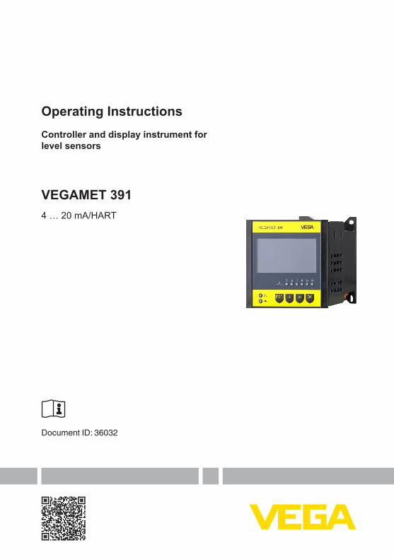
Operating InstructionsController and display instrument for level sensors
VEGAMET 3914 … 20 mA/HART
Document ID: 36032

2
Contents
VEGAMET 391 • 4 … 20 mA/HART
36032-EN-210818
Contents1 About this document ............................................................................................................... 4
1.1 Function ........................................................................................................................... 41.2 Target group ..................................................................................................................... 41.3 Symbols used................................................................................................................... 4
2 For your safety ......................................................................................................................... 52.1 Authorised personnel ....................................................................................................... 52.2 Appropriate use ................................................................................................................ 52.3 Warning about incorrect use ............................................................................................. 52.4 General safety instructions ............................................................................................... 52.5 Installation and operation in the USA and Canada ........................................................... 62.6 Safety instructions for Ex areas ........................................................................................ 6
3 Product description ................................................................................................................. 73.1 Configuration .................................................................................................................... 73.2 Principle of operation........................................................................................................ 83.3 Adjustment ....................................................................................................................... 83.4 Packaging, transport and storage ..................................................................................... 9
4 Mounting ................................................................................................................................. 104.1 General instructions ....................................................................................................... 104.2 Mounting instructions ..................................................................................................... 10
5 Connecting to power supply ................................................................................................. 135.1 Preparing the connection ............................................................................................... 135.2 Sensor input mode active/passive .................................................................................. 135.3 Connection procedure .................................................................................................... 145.4 Wiring plan ..................................................................................................................... 15
6 Setup with the integrated display and adjustment unit ..................................................... 176.1 Adjustment system ......................................................................................................... 176.2 Setup steps .................................................................................................................... 186.3 Menu schematic ............................................................................................................. 29
7 Setup with PACTware ............................................................................................................. 377.1 Connect the PC .............................................................................................................. 377.2 Parameter adjustment with PACTware ............................................................................ 397.3 Setup web server/e-mail, remote enquiry ....................................................................... 40
8 Application examples ............................................................................................................ 418.1 Levelmeasurementinahorizontalcylindricaltankwithoverfillprotection/dryrunprotec-
tion ................................................................................................................................. 418.2 Pump control 1/2 (run time controlled) ............................................................................ 428.3 Pump control 3/4 (sequentially controlled) ..................................................................... 468.4 Tendency recognition ..................................................................................................... 498.5 Flow measurement ......................................................................................................... 50
9 Diagnostics and servicing .................................................................................................... 539.1 Maintenance .................................................................................................................. 539.2 Rectify faults ................................................................................................................... 539.3 Diagnosis, fault messages ............................................................................................. 539.4 How to proceed if a repair is necessary .......................................................................... 55

3
Contents
VEGAMET 391 • 4 … 20 mA/HART
3603
2-EN
-210
818
10 Dismount................................................................................................................................. 5710.1 Dismounting steps.......................................................................................................... 5710.2 Disposal ......................................................................................................................... 57
11 Certificatesandapprovals .................................................................................................... 5811.1 Approvals for Ex areas ................................................................................................... 5811.2 Approvalsasoverfillprotection ....................................................................................... 5811.3 EU conformity ................................................................................................................. 5811.4 Environment management system ................................................................................. 58
12 Supplement ............................................................................................................................ 5912.1 Technical data ................................................................................................................ 5912.2 Overview applications/functionality ................................................................................ 6312.3 Dimensions .................................................................................................................... 6412.4 Industrial property rights ................................................................................................. 6512.5 Trademark ...................................................................................................................... 65
Editing status: 2021-08-17

4
1 About this document
VEGAMET 391 • 4 … 20 mA/HART
36032-EN-210818
1 About this document
1.1 FunctionThis instruction provides all the information you need for mounting, connection and setup as well as important instructions for mainte-nance,faultrectification,theexchangeofpartsandthesafetyoftheuser. Please read this information before putting the instrument into operation and keep this manual accessible in the immediate vicinity of the device.
1.2 Target groupThis operating instructions manual is directed to trained personnel. Thecontentsofthismanualmustbemadeavailabletothequalifiedpersonnel and implemented.
1.3 Symbols usedDocument IDThis symbol on the front page of this instruction refers to the Docu-ment ID. By entering the Document ID on www.vega.com you will reach the document download. Information, note, tip: This symbol indicates helpful additional infor-mation and tips for successful work. Note: This symbol indicates notes to prevent failures, malfunctions, damage to devices or plants. Caution: Non-observance of the information marked with this symbol may result in personal injury. Warning: Non-observance of the information marked with this symbol may result in serious or fatal personal injury. Danger: Non-observance of the information marked with this symbol results in serious or fatal personal injury.
Ex applicationsThis symbol indicates special instructions for Ex applications.
• ListThe dot set in front indicates a list with no implied sequence.
1 Sequence of actionsNumbers set in front indicate successive steps in a procedure.
Battery disposalThis symbol indicates special information about the disposal of bat-teries and accumulators.
5
2 For your safety
VEGAMET 391 • 4 … 20 mA/HART
3603
2-EN
-210
818
2 For your safety
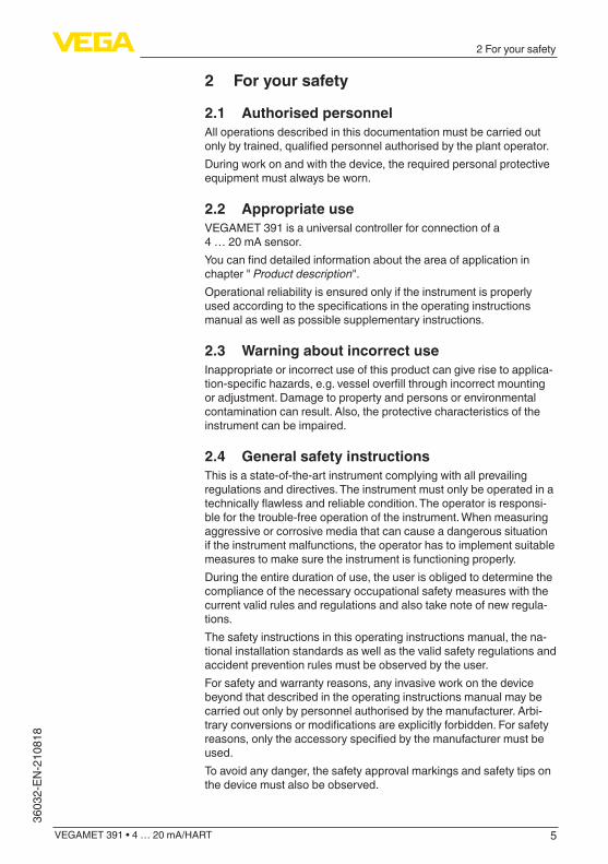
2.1 Authorised personnelAll operations described in this documentation must be carried out onlybytrained,qualifiedpersonnelauthorisedbytheplantoperator.During work on and with the device, the required personal protective equipment must always be worn.
2.2 Appropriate useVEGAMET 391 is a universal controller for connection of a 4 … 20 mA sensor. Youcanfinddetailedinformationabouttheareaofapplicationinchapter " Product description". Operational reliability is ensured only if the instrument is properly usedaccordingtothespecificationsintheoperatinginstructionsmanual as well as possible supplementary instructions.
2.3 Warning about incorrect useInappropriate or incorrect use of this product can give rise to applica-tion-specifichazards,e.g.vesseloverfillthroughincorrectmountingor adjustment. Damage to property and persons or environmental contamination can result. Also, the protective characteristics of the instrument can be impaired.
2.4 General safety instructionsThis is a state-of-the-art instrument complying with all prevailing regulations and directives. The instrument must only be operated in a technicallyflawlessandreliablecondition.Theoperatorisresponsi-ble for the trouble-free operation of the instrument. When measuring aggressive or corrosive media that can cause a dangerous situation if the instrument malfunctions, the operator has to implement suitable measures to make sure the instrument is functioning properly.During the entire duration of use, the user is obliged to determine the compliance of the necessary occupational safety measures with the current valid rules and regulations and also take note of new regula-tions.The safety instructions in this operating instructions manual, the na-tional installation standards as well as the valid safety regulations and accident prevention rules must be observed by the user.For safety and warranty reasons, any invasive work on the device beyond that described in the operating instructions manual may be carried out only by personnel authorised by the manufacturer. Arbi-traryconversionsormodificationsareexplicitlyforbidden.Forsafetyreasons,onlytheaccessoryspecifiedbythemanufacturermustbeused.To avoid any danger, the safety approval markings and safety tips on the device must also be observed.

6
2 For your safety
VEGAMET 391 • 4 … 20 mA/HART
36032-EN-210818
2.5 Installation and operation in the USA and Canada
This information is only valid for USA and Canada. Hence the follow-ing text is only available in the English language.Installations in the US shall comply with the relevant requirements of the National Electrical Code (ANSI/NFPA 70).Installations in Canada shall comply with the relevant requirements of the Canadian Electrical Code.
2.6 Safety instructions for Ex areasFor applications in explosion-proof areas (Ex), only devices with cor-respondingExapprovalmaybeused.ObservetheEx-specificsafetyinstructions. These are an integral part of the operating instructions and are enclosed with every device with Ex approval.

7
3 Product description
VEGAMET 391 • 4 … 20 mA/HART
3603
2-EN
-210
818
3 Product description
3.1 ConfigurationThe scope of delivery encompasses:
• Controller VEGAMET 391 • Two clamping elements for panel mounting• Ex separating wall• Mini-USB cable• Carrier rail adapter (optional)• RS232 modem connection cable (optional)• Documentation
– This operating instructions manual – Supplementary instruction 30325 " RS232/Ethernet connec-
tion" (optional) – Supplementary instructions manual 30768 " Modbus-TCP,
ASCII protocol" (optional) – Ex-specific"Safety instructions" (with Ex version) – Ifnecessary,furthercertificates
OKESCon
VEGAMET 391
1 2 3 4 5 6
12
3
4
2
5
Fig. 1: VEGAMET 3911 Ex separating wall2 Clamping element for panel mounting3 Display and adjustment unit4 RS232 or Ethernet interface (optional)5 USB interface
Thetypelabelcontainsthemostimportantdataforidentificationanduse of the instrument:
• Instrument type• Information about approvals• Technical data• Serial number of the instrument• QR code for device documentation• Manufacturer information
The type label contains the serial number of the instrument. With it youcanfindthefollowingdataonourhomepage:
• Product code of the instrument (HTML)
Scope of delivery
Constituent parts
Type label
Serial number
8
3 Product description
VEGAMET 391 • 4 … 20 mA/HART
36032-EN-210818
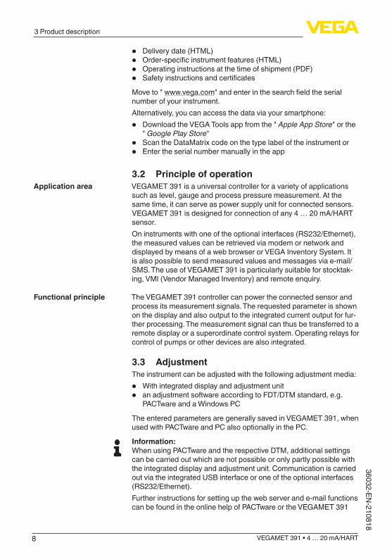
• Delivery date (HTML)• Order-specificinstrumentfeatures(HTML)• Operating instructions at the time of shipment (PDF)• SafetyinstructionsandcertificatesMove to " www.vega.com"andenterinthesearchfieldtheserialnumber of your instrument. Alternatively, you can access the data via your smartphone:
• Download the VEGA Tools app from the " Apple App Store" or the " Google Play Store"
• Scan the DataMatrix code on the type label of the instrument or• Enter the serial number manually in the app
3.2 Principle of operationVEGAMET 391 is a universal controller for a variety of applications such as level, gauge and process pressure measurement. At the same time, it can serve as power supply unit for connected sensors. VEGAMET 391 is designed for connection of any 4 … 20 mA/HART sensor. On instruments with one of the optional interfaces (RS232/Ethernet), the measured values can be retrieved via modem or network and displayed by means of a web browser or VEGA Inventory System. It is also possible to send measured values and messages via e-mail/SMS. The use of VEGAMET 391 is particularly suitable for stocktak-ing, VMI (Vendor Managed Inventory) and remote enquiry.
The VEGAMET 391 controller can power the connected sensor and process its measurement signals. The requested parameter is shown on the display and also output to the integrated current output for fur-ther processing. The measurement signal can thus be transferred to a remote display or a superordinate control system. Operating relays for control of pumps or other devices are also integrated.
3.3 AdjustmentThe instrument can be adjusted with the following adjustment media:
• With integrated display and adjustment unit• an adjustment software according to FDT/DTM standard, e.g.
PACTware and a Windows PC
The entered parameters are generally saved in VEGAMET 391, when used with PACTware and PC also optionally in the PC.
Information:When using PACTware and the respective DTM, additional settings can be carried out which are not possible or only partly possible with the integrated display and adjustment unit. Communication is carried out via the integrated USB interface or one of the optional interfaces (RS232/Ethernet).Further instructions for setting up the web server and e-mail functions can be found in the online help of PACTware or the VEGAMET 391
Application area
Functional principle

9
3 Product description
VEGAMET 391 • 4 … 20 mA/HART
3603
2-EN
-210
818
DTMs as well as the operating instructions manual " RS232/Ethernet connection".
3.4 Packaging, transport and storageYour instrument was protected by packaging during transport. Its capacity to handle normal loads during transport is assured by a test based on ISO 4180.The packaging of standard instruments consists of environment-friendly, recyclable cardboard. For special versions, PE foam or PE foil is also used. Dispose of the packaging material via specialised recycling companies.
Transport must be carried out in due consideration of the notes on the transport packaging. Nonobservance of these instructions can cause damage to the device.
The delivery must be checked for completeness and possible transit damage immediately at receipt. Ascertained transit damage or con-cealed defects must be appropriately dealt with.
Up to the time of installation, the packages must be left closed and stored according to the orientation and storage markings on the outside.Unless otherwise indicated, the packages must be stored only under the following conditions:
• Not in the open• Dry and dust free• Not exposed to corrosive media• Protected against solar radiation• Avoiding mechanical shock and vibration
• Storage and transport temperature see chapter " Supplement - Technical data - Ambient conditions"
• Relative humidity 20 … 85 %
Packaging
Transport
Transport inspection
Storage
Storage and transport temperature

10
4 Mounting
VEGAMET 391 • 4 … 20 mA/HART
36032-EN-210818
4 Mounting
4.1 General instructionsThe instrument is designed for recessed installation in an instrument panel, housing front plate or switching cabinet door. The required cut-out is 92 x 92 mm (3.63 x 3.63 in) according to EN 60529. When installed correctly, protection rating IP65 is guaranteed. As an alterna-tive, the instrument can be mounted in a switching cabinet or protec-tive housing by means of four screws (attached with screws to rear of housing). A mounting adapter for carrier rail mounting is available as an option (top hat rail 35 x 7.5 according to DIN EN 50022/60715).
Note:If the instrument is mounted via screws or carrier rail, it must always be inside a switching cabinet or protective case.
A VEGAMET 391 in Ex version is an auxiliary, intrinsically safe instru-ment and may not be installed in explosion-endangered areas. Before setup, the Ex separating wall must be attached to Ex versions. Safe operation can only be ensured if the operating instructions manualandtheECtypeapprovalcertificateareobserved.VEGAMET391 must not be opened.
The instrument is suitable for standard ambient conditions acc. to DIN/EN/IEC/ANSI/ISA/UL/CSA 61010-1.Makesurethatthedegreeofcontaminationspecifiedinchapter"Technical data" meets the existing ambient conditions.
4.2 Mounting instructions1. Make sure that the cut-out required for mounting has a size of
92 x 92 mm (3.63 x 3.63 in).2. Check for the correct position of the seal directly behind the front
plate and insert the instrument from the front into the front panel cut-out.
3. Press the two tensioning elements into the provided gaps.4. Screw in the two screws of the tensioning elements evenly with a
screwdriver.
Installation possibilities
Ambient conditions
Front panel mounting

11
4 Mounting
VEGAMET 391 • 4 … 20 mA/HART
3603
2-EN
-210
818
3
2
1
Fig. 2: Front panel mounting1 Front panel, front plate or switching cabinet door2 Clamping elements3 Slotted screw
→ Fasten the instrument by means of four screws (max. ø 4 mm) to the inner side of the housing or to the mounting plate according to the following illustration.
73 mm (2.87")
86,5
mm
(3.4
1")
1
2
Fig. 3: Screw mounting1 Fixing screw2 Rear of the housing or mounting plate
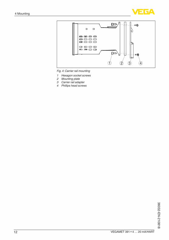
1. Fasten the mounting plate to the instrument with the four en-closed hexagon socket screws.
2. Screw the carrier rail adapter to the mounting plate with the four enclosed Phillips-head screws.
Screw mounting
Carrier rail mounting
12
4 Mounting
VEGAMET 391 • 4 … 20 mA/HART
36032-EN-210818
1 2 3 4
Fig. 4: Carrier rail mounting1 Hexagon socket screws2 Mounting plate3 Carrier rail adapter4 Phillips head screws

13
5 Connecting to power supply
VEGAMET 391 • 4 … 20 mA/HART
3603
2-EN
-210
818
5 Connecting to power supply
5.1 Preparing the connectionAlways keep in mind the following safety instructions:
Warning:Connect only in the complete absence of line voltage.
• Connect only in the complete absence of line voltage• If overvoltage surges are expected, overvoltage arresters should
be installed
Note:Install a disconnecting device for the instrument which is easy to access. The disconnecting device must be marked for the instrument (IEC/EN 61010).
In hazardous areas you must take note of the respective regulations, conformityandtypeapprovalcertificatesofthesensorsandpowersupply units.
Thedataforpowersupplyarespecifiedinchapter"Technical data".
The voltage supply of VEGAMET 391 is connected with standard cable according to the national installation standards. Standard two-wire cable can be used for connecting the sensors. The screening is absolutely necessary to ensure interference-free opera-tion with HART sensors.Make sure that the cable used has the required temperature resist-anceandfiresafetyformax.occurringambienttemperature
Connect the cable shielding on both ends to ground potential. In the sensor, the shielding must be connected directly to the internal ground terminal. The ground terminal on the outside of the sensor housing must be connected to the potential equalisation (low imped-ance).If potential equalisation currents are expected, the screen connection on the side of VEGAMET 391 must be made via a ceramic capacitor (e. g. 1 nF, 1500 V). The low frequency potential equalisation currents arethussuppressed,buttheprotectiveeffectagainsthighfrequencyinterference signals remains. Take note of the corresponding installation regulations for Ex applica-tions. In particular, make sure that no potential equalisation currents flowoverthecablescreen.Incaseofgroundingonbothsidesthiscan be achieved by the use of a capacitor or a separate potential equalisation.
5.2 Sensor input mode active/passiveThrough the selection of the terminals, you can choose between ac-tive and passive operation of the sensor input.
Safety instructions
Safety instructions for Ex applications
Voltage supply
Connection cable
Cable screening and grounding
Connection cable for Ex applications

14
5 Connecting to power supply
VEGAMET 391 • 4 … 20 mA/HART
36032-EN-210818
• In active mode, the controller provides the power for the con-nected sensors. Power and measurement data are transmitted over the same two-wire cable. This mode is provided for connec-tion of measuring transducers without separate power supply (sensors in two-wire version).
• In passive mode the sensors are not powered, only the measured value is transmitted. This input is for connection of transmitters with their own separate voltage supply (sensors in four-wire ver-sion). The VEGAMET 391 can also be looped into the existing circuit like a normal ammeter.
Note:With a VEGAMET 391 in Ex version, the passive input is not available.
5.3 Connection procedureMove on to electrical connection and proceed as follows:1. Mount the instrument as described in the previous chapter2. Remove terminal strip 1 on the upper side of the instrument3. Connect sensor cable to terminal 1/2 (active input) or 5/6 (passive
input)4. If necessary, connect digital inputs to 8 … 125. Plug terminal strip 1 to the upper side of the instrument6. Remove terminal strip 2 on the lower side of the instrument7. Connectpowersupply(switchedoff)toterminal13/148. If necessary, connect relays or other outputs9. Plug in terminal strip 2 on the lower side of the instrument10. For connection of additional relais to terminal strip 3, you have to
proceed as described earlierTheelectricalconnectionisfinished.Remember that with Ex applications, the Ex separating wall must be plugged onto the upper side of the instrument before setup.

15
5 Connecting to power supply
VEGAMET 391 • 4 … 20 mA/HART
3603
2-EN
-210
818
5.4 Wiring plan
87 11103 95421 6 12
1718 141522 1620212324 19 13
2930 262734 2832333536 31 25
+- L+N-
+ + + + + --
5 4 36
9
1 7 82
10 11 12 13
14
OKESCon
1 2 3 4 5 6
Fig. 5: Wiring plan with two-wire sensor1 Internal relay 12 Internal relay 23 Internal relay 34 Internal relay 45 Internal relay 56 Internal relay 67 4 … 20 mA current output8 Voltage supply of the controller9 Measurement data input with sensor supply (active input)10 Connection for HART modem for sensor parameter adjustment11 Measurement data input (passive input), not with Ex-ia version12 Digital input 1 … 413 Common ground for digital input 1 … 414 4 … 20 mA/HART sensor (two-wire version)
Wiring plan for two-wire sensor

16
5 Connecting to power supply
VEGAMET 391 • 4 … 20 mA/HART
36032-EN-210818
+ + + + + --
9 10 11 12
14 15
13
OKESCon
1 2 3 4 5 6
87 11103 95421 6 12
1718 141522 1620212324 19 13
2930 262734 2832333536 31 25
+- L+N-
5 4 36
1 7 82
Fig. 6: Terminal assignment with four-wire sensor1 Internal relay 12 Internal relay 23 Internal relay 34 Internal relay 45 Internal relay 56 Internal relay 67 4 … 20 mA current output8 Voltage supply of the controller9 Measurement data input with sensor supply (active input)10 Connection for HART modem for sensor parameter adjustment11 Measurement data input (passive input), not with Ex-ia version12 Digital input 1 … 413 Common ground for digital input 1 … 414 4 … 20 mA/HART sensor (four-wire version)15 Voltage supply for four-wire sensor
Wiring plan for four-wire sensor
17
6 Setup with the integrated display and adjustment unit
VEGAMET 391 • 4 … 20 mA/HART
3603
2-EN
-210
818
6 Setup with the integrated display and adjustment unit
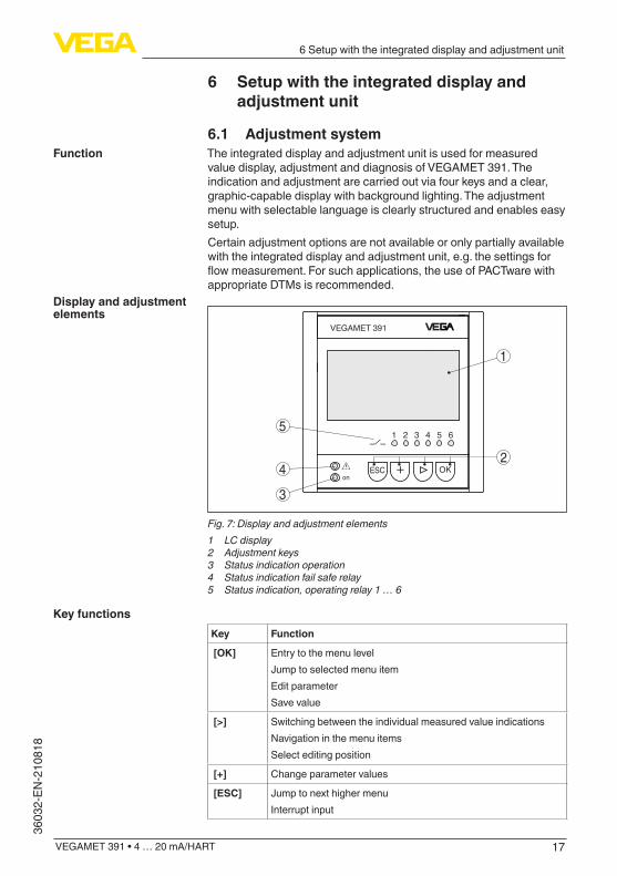
6.1 Adjustment systemThe integrated display and adjustment unit is used for measured value display, adjustment and diagnosis of VEGAMET 391. The indication and adjustment are carried out via four keys and a clear, graphic-capable display with background lighting. The adjustment menu with selectable language is clearly structured and enables easy setup. Certain adjustment options are not available or only partially available with the integrated display and adjustment unit, e.g. the settings for flowmeasurement.Forsuchapplications,theuseofPACTwarewithappropriate DTMs is recommended.
OKESCon
VEGAMET 391
1 2 3 4 5 6
4
5
3
2
1
Fig. 7: Display and adjustment elements1 LC display2 Adjustment keys3 Status indication operation4 Status indication fail safe relay5 Status indication, operating relay 1 … 6
Key Function
[OK] Entry to the menu levelJump to selected menu itemEdit parameterSave value
[>] Switching between the individual measured value indicationsNavigation in the menu itemsSelect editing position
[+] Change parameter values
[ESC] Jump to next higher menuInterrupt input
Function
Display and adjustment elements
Key functions

18
6 Setup with the integrated display and adjustment unit
VEGAMET 391 • 4 … 20 mA/HART
36032-EN-210818
6.2 Setup stepsThrough parameter adjustment, the instrument is adapted to the indi-vidual application conditions. A measurement loop calibration is the most important step and should always be carried out. A scaling of the measured value to the desired physical variable and unit, possibly including a linearisation curve, is often useful. The adaptation of the relay switching points or the setting of an integration time to smooth the measured value are further standard adjustment options.Instruments with Ethernet interface can be provided with a Host name suitable for the measurement loop. As an alternative to the addressing via DHCP, it is also possible to adjust an IP address and subnet mask suitable for your network. If necessary, the e-mail/Web server can be alsoconfiguredwithPACTware.A setup assistant is available for easy, convenient setup. It guides the user through the standard applications and settings step by step.
Information:When using PACTware and the respective DTM, additional settings can be carried out which are not possible or only partly possible with the integrated display and adjustment unit. Communication is carried out via the integrated USB interface or one of the optional interfaces (RS232/Ethernet).Further instructions for setting up the web server and e-mail functions are stated in the online help of PACTware or the VEGAMET 391 DTMs as well as the supplementary instructions manual " RS232/Ethernet connection".
Afterbeingswitchedon,VEGAMET391firstofallcarriesoutashortself-check. The following steps are carried out:
• Internal check of the electronics• indicationoftheinstrumenttype,firmwareversionaswellasthe
instrument TAG (instrument name)• TheoutputsignalsjumpbrieflytothesetfaultvalueThen the current measured values will be displayed and output.
The measured value indication shows the digitally indicated value, the measurement loop name (measurement loop TAG) and the unit. An analoguebargraphcanalsobedisplayed.Ifflowmeasurementwithtotalizer is activated, an additional indication window with totalizers becomes available. If pump control is activated, an additional meas-ured value indication of the assigned pumps is available. By pushing the [>]keyyoucanmovebetweenthedifferentdisplayoptions.
→ By pressing [OK], you move from measured value indication to the main menu. Here you can choose between the setup as-sistant for the most important settings and the complete classic menu.
Parameter adjustment
Switch-on phase
Measured value indica-tion

19
6 Setup with the integrated display and adjustment unit
VEGAMET 391 • 4 … 20 mA/HART
3603
2-EN
-210
818
At the beginning of every setup or parameter adjustment, you have the choice of continuing with the setup assistant or the classic menu guidance. We recommend using the setup assistant for the initial setup. If individual settings need to be corrected or added later, the most expedient way to do this is to use the classic menus.
→ Select the menu item " Setup assistant" with [->]andconfirmwith[OK].
The setup assistant leads you step-by-step through the standard set-tings. The following steps are carried out:
• Device-TAG (individually adjustable instrument name)• Measurement loop TAG (individually adjustable measurement loop
designation)• Type of input (4 … 20 mA or HART)• Measured variable (for example level or process pressure)• Adjustment unit (for example m or bar)• Min./Max. adjustment• Activation of the fail safe relay• Configurationoftherelayoutputs(e.g.setupofpumpcontrolor
overfillprotection)• Setting Date/Time with option RS232/Ethernet interface• Network settings with option "Ethernet interface"
When changing the measurement, the assistant can be called up any time. The subsequent steps can also be reached individually via the traditional menu navigation. A description of the individual menu items is available in the traditional menus. In chapter " Application examples"youwillfindfurtherinformationaboutsetup.
The main menu is divided into six areas with the following functions:
• Device settings: Includes the device-TAG, settings for network connection such as date/time setting, …
• Measurement loop: Includes settings for input selection, adjust-ment, damping, linearisation, scaling, outputs, …
• Display: Includes settings for the displayed measured value, language and brightness of the background lighting
• Diagnosis Includes information on device status, error messages, input current, digital inputs
• Further settings: Includes simulation, reset, PIN, sensor address, …
• Info: Shows serial number, software version, last change, instru-ment features, MAC addr., …
Main menu/Setup as-sistant
Setup assistant
Traditional menu naviga-tion/main menu
20
6 Setup with the integrated display and adjustment unit
VEGAMET 391 • 4 … 20 mA/HART
36032-EN-210818
→ Select the requested menu item via the respective keys and confirmwith[OK].
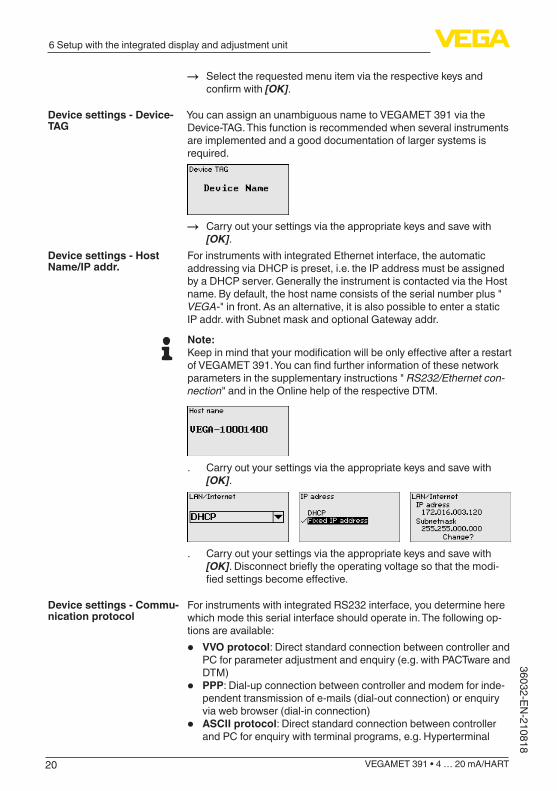
You can assign an unambiguous name to VEGAMET 391 via the Device-TAG. This function is recommended when several instruments are implemented and a good documentation of larger systems is required.
→ Carry out your settings via the appropriate keys and save with [OK].
For instruments with integrated Ethernet interface, the automatic addressing via DHCP is preset, i.e. the IP address must be assigned by a DHCP server. Generally the instrument is contacted via the Host name. By default, the host name consists of the serial number plus " VEGA-" in front. As an alternative, it is also possible to enter a static IP addr. with Subnet mask and optional Gateway addr.
Note:KeepinmindthatyourmodificationwillbeonlyeffectiveafterarestartofVEGAMET391.Youcanfindfurtherinformationofthesenetworkparameters in the supplementary instructions " RS232/Ethernet con-nection" and in the Online help of the respective DTM.
. Carry out your settings via the appropriate keys and save with [OK].
. Carry out your settings via the appropriate keys and save with [OK].Disconnectbrieflytheoperatingvoltagesothatthemodi-fiedsettingsbecomeeffective.
For instruments with integrated RS232 interface, you determine here which mode this serial interface should operate in. The following op-tions are available:
• VVO protocol: Direct standard connection between controller and PC for parameter adjustment and enquiry (e.g. with PACTware and DTM)
• PPP: Dial-up connection between controller and modem for inde-pendent transmission of e-mails (dial-out connection) or enquiry via web browser (dial-in connection)
• ASCII protocol: Direct standard connection between controller and PC for enquiry with terminal programs, e.g. Hyperterminal
Device settings - Device-TAG
Device settings - Host Name/IP addr.
Device settings - Commu-nication protocol

21
6 Setup with the integrated display and adjustment unit
VEGAMET 391 • 4 … 20 mA/HART
3603
2-EN
-210
818
→ Carry out your settings via the respective keys and save with [OK]. Further information is available in the supplementary instructions manual " RS232/Ethernet connection" and the online help of the respective DTM.
With instruments with integrated RS232/Ethernet interface, the date and time can be entered in this menu item. These time settings are bufferedincaseofvoltagelossviaacapacitoraswellasasbatteryup to 10 years.
→ Carry out your settings via the appropriate keys and save with [OK].
The VEGAMET 391 can process measured values from 4 … 20 mA/HART sensors via analogue communication as well as via digital HART protocol.
Analogue 4 … 20 mA transmissionIn the standard setting of VEGAMET 391 the measured value trans-mission is carried out via analogue 4 … 20 signal. An adjustment in thesensorinfluencesdirectlytheinputvariableofVEGAMET391.Only carry out the adjustment on one instrument, either on VEGAMET 391 or on the sensor. The adjustment in VEGAMET 391 is always car-ried out in mA (analogue transmission).
Digital HART transmissionFor transmission via HART, VEGAMET 391 must be informed which sensor value should be used for further processing. Depending on the sensor type, this can be distance, pressure or temperature. With all HART sensors, the unchanged initial value of the sensor is always transmitted to VEGAMET 391. Thus, adjustment must always be car-riedoutonVEGAMET391,neveronthesensor.Differentparametersand measuring units are available. When HART sensors from other manufacturers are connected, the options PV (Primary Value) and SV (Secondary Value) are available. The prerequisite for this is the support of the HART commands 0, 1, 3, and 15. This information and which measured values are transmit-ted can be found in the operating instructions manual of the respec-tive sensor manufacturer.
Carry out your settings via the appropriate keys and save with [OK].
Device settings - Date/Time
Measurement loop - Input

22
6 Setup with the integrated display and adjustment unit
VEGAMET 391 • 4 … 20 mA/HART
36032-EN-210818
Themeasuredvariabledefinestheapplicatonofthemeasurementloop, the following settings are available depending on the connected sensor:
• Level• Process pressure• Universal• Temperature• Interface• Flow (only after activating via PACTware or DTM)
Carry out your settings via the appropriate keys and save with [OK].
Through the adjustment the input value of the connected sensor is converted into a percentage value. This conversion step allows any input value range to be depicted in a relative range (0 % up to 100 %).Before carrying out the adjustment, the requested adjustment unit can be selected. With input selection " Analogue", the adjustment unit is always " mA". If the HART input is activated, the available unit depends on the sensor type. With radar, ultrasonic and guided micro-wave this is always the distance in metres or feet " m(d)" or " ft(d)", and with pressure transmitters it is e.g. " bar" or " psi".
The following illustrations and examples relate to the min./max. ad-justment of a radar sensor with HART communication.
. With [OK] you prepare the percentage value for editing, with [->] you place the cursor to the requested position. Set the requested percentage value with [+] and save with [OK].
. After entering the percentage value for the min. adjustment, the suitable distance value must be entered. If you want the use the currently measured distance value, select the menu item " Accept" (live adjustment or adjustment with medium). If the adjustment should be carried out independent of the measured level, then select the option " Edit". Enter now the distance value in m [m(d)] for the empty vessel that is suitable for the percent-age value, e.g. distance from the sensor to the vessel bottom (dry adjustment or adjustment without medium).
. Save your settings with [OK] and move to "Max. adjustment" with [->].
Meas. loop - Parameter
Meas. loop - Adjustment
23
6 Setup with the integrated display and adjustment unit
VEGAMET 391 • 4 … 20 mA/HART
3603
2-EN
-210
818
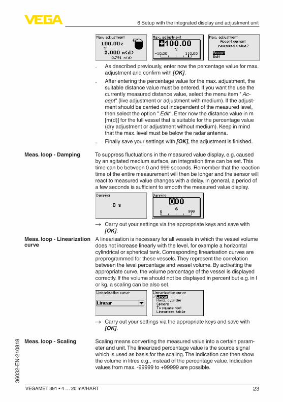
. As described previously, enter now the percentage value for max. adjustmentandconfirmwith[OK].
. After entering the percentage value for the max. adjustment, the suitable distance value must be entered. If you want the use the currently measured distance value, select the menu item " Ac-cept" (live adjustment or adjustment with medium). If the adjust-ment should be carried out independent of the measured level, then select the option " Edit". Enter now the distance value in m [m(d)] for the full vessel that is suitable for the percentage value (dry adjustment or adjustment without medium). Keep in mind that the max. level must be below the radar antenna.
. Finally save your settings with [OK],theadjustmentisfinished.
Tosuppressfluctuationsinthemeasuredvaluedisplay,e.g.causedby an agitated medium surface, an integration time can be set. This time can be between 0 and 999 seconds. Remember that the reaction time of the entire measurement will then be longer and the sensor will react to measured value changes with a delay. In general, a period of afewsecondsissufficienttosmooththemeasuredvaluedisplay.
→ Carry out your settings via the appropriate keys and save with [OK].
A linearisation is necessary for all vessels in which the vessel volume does not increase linearly with the level, for example a horizontal cylindrical or spherical tank. Corresponding linearisation curves are preprogrammed for these vessels. They represent the correlation between the level percentage and vessel volume. By activating the appropriate curve, the volume percentage of the vessel is displayed correctly. If the volume should not be displayed in percent but e.g. in l or kg, a scaling can be also set.
→ Carry out your settings via the appropriate keys and save with [OK].
Scaling means converting the measured value into a certain param-eter and unit. The linearized percentage value is the source signal which is used as basis for the scaling. The indication can then show the volume in litres e.g., instead of the percentage value. Indication values from max. -99999 to +99999 are possible.
Meas. loop - Damping
Meas. loop - Linearization curve
Meas. loop - Scaling

24
6 Setup with the integrated display and adjustment unit
VEGAMET 391 • 4 … 20 mA/HART
36032-EN-210818
→ Carry out your settings via the appropriate keys and save with [OK].
In this menu item you can enter an unambiguous designation for each measurement loop, e.g. the measurement loop name or the tank or product designation. In digital systems and in the documentation of larger plants, a singular designation should be entered for exact identificationofindividualmeasuringpoints.
→ Carry out your settings via the appropriate keys and save with [OK].
Under " Outputs"youcanfindtherelayandcurrentoutputs.Sixrelaysare available for use. Relay 1 is assigned to the measurement loop. Relays 2 … 5 are available and not yet assigned to a function. The relays must be activated before they can be used. Toconfiguretherelayoutput,therequestedmode("Overfill protec-tion/Dry run protection" or " Pump control")mustfirstbeselected.
• Overfillprotection:Relayisswitchedoffwhenthemax.levelisexceeded (safe currentless state), relay is switched on again when thelevelfallsbelowthemin.level(switch-onpoint<switch-offpoint)
• Dry run protection:Relayisswitchedoffwhenthelevelfallsbelow the min. level (safe currentless state), relay is switched on again when the max. level is exceeded (switch-on point > switch-offpoint)
• Pump control: With several pumps having the same function, the pumpswillbealternatelyswitchonandoffaccordingtotheadjust-able criteria
Additional modes such as " Switching window", " Flow" and " Ten-dency" can be only adjusted via PACTware and DTM. Relay6canbealsoconfiguredasfailsaferelay.Thefollowingexam-pleshowsthesettingofanoverfillprotection.Furtherinformationtopumpcontrol,tendencyrecognitionorflowmeasurementareavail-able in chapter " Application examples".
Meas. loop - Meas. loop TAG
Meas. loop - Outputs - Relays outputs

25
6 Setup with the integrated display and adjustment unit
VEGAMET 391 • 4 … 20 mA/HART
3603
2-EN
-210
818
Select the requested mode and save with [OK]. By pushing [->], you reach the next menu item. . Now enter the reference value to which the relay switching points
relate. By pushing [->], you reach the next menu item.
. Nowentertheswitchingpointsforswitchingtherelayonandoff.
In the following window the reaction of the relay in case of failure can bedetermined.Hereyoucandefinewhether,incaseoffailure,theswitching condition of the relay remains unchanged or the relay is switchedoff.
The current output is used to transfer the measured value to a higher ranking system, for example to a PLC, a control system or a meas-ured value indication. This is an active output, i.e. a current is provided actively. The processing unit must hence have a passive current input.The characteristics of the current output can be set to 0 … 20 mA, 4 … 20 mA or inverted. The reaction in case of failure can also be adapted to the requirements. The measured variable you refer to can also be selected.
→ Carry out your settings via the appropriate keys and save with [OK].
In the menu item " Display - Indication value", you can set the re-quested indication value. The following options are available:
Meas. loop - Outputs - Current output
Display - Indicated value

26
6 Setup with the integrated display and adjustment unit
VEGAMET 391 • 4 … 20 mA/HART
36032-EN-210818
• Percent: adjusted measured value without taking a saved lineari-sation into account
• Lin. percent: adjusted measured value taking a saved linearisa-tion into account
• Scaled: adjusted measured value taking a saved linearisation into account as well as the values entered under " Scaling"
• Sensor value: input value delivered by the sensor. Displayed in the selected adjustment unit
→ Carry out your settings via the appropriate keys and save with [OK].
In the menu item " Display - Language", the requested display lan-guage can be adjusted. The following languages are available:
• German• English• French• Spanish• Russian• Italian• Dutch
→ Carry out your settings via the appropriate keys and save with [OK].
In the menu item " Display - Brightness", the brightness of the back-ground lighting can be continuously adjusted.
→ Carry out your settings via the appropriate keys and save with [OK].
When the instrument displays a fault signal, further information about the fault can be called up via the menu item " Diagnosis - Device sta-tus". Furthermore, the input current, the sensor status and the input status of the digital inputs can be displayed. The status of the relay, its switched-on period and the number of switch-on events can also be displayed. The counters can also be reset.
Display - Language
Display - Brightness
Diagnostics

27
6 Setup with the integrated display and adjustment unit
VEGAMET 391 • 4 … 20 mA/HART
3603
2-EN
-210
818
The simulation of a measured value is used to check the outputs and connected components. The simulation can be applied to the percent-age value, the lin. percentage value and the sensor value.
Note:Please note that connected system components (valves, pumps, motors,controlsystems)areinfluencedbythesimulation,thusunintentional plant operating conditions can occur. The simulation is terminated automatically after approxminately 10 minutes.
→ Carry out your settings via the appropriate keys and save with [OK].
Several reset options are available. A reset to basic settings resets all settings (with a view exceptions) to default. Exceptions are: host name, IP address, subnet mask, time, language. Further possibilities are reset of the totalizer as well as the power-on time and relay failure. The instrument can also be restarted if desired.
The controller can be locked and the data transmission encrypted as a protection against unauthorized changes of the set parameters. The following options are possible:
• Access protection of the on-site adjustment via keyboard by means of a PIN
• Access protection of the DTM adjustment via the USB/Ethernet/RS232 interface by means of a password (can be only activated via DTM)
• Encryption of the DTM data transmission with connection via Ethernet/RS232 interface
• Access protection of the integrated web server by means of a password (can be only activated via DTM)
Additional adjustments - Simulation
Additional settings - Reset
Additional adjustments - Access protection

28
6 Setup with the integrated display and adjustment unit
VEGAMET 391 • 4 … 20 mA/HART
36032-EN-210818
Modificationofparametersthroughtheinstrumentkeyboardcanbeavoided by activating a PIN. The measured value display and display of all parameters is still possible.
Note:By activating the PIN, only parameter changes via the front side instrument keyboard are locked. Via the interfaces and the respective DTM, the complete access to the instrument is still possible. If you want to stop this access, then the DTM adjustment can be completely locked by activating a password. The activation of this locking only possible via the DTM and not via the keyboard.
Instruments with RS232/Ethernet option can be protected against wiretapping and manipulation of the data transmission from remote. For this, activate under " DTM remote access" the encryption of the data transmission. With active encryption, it is necessary to enter once the instrument key (PSK) during connection for DTM access via the Ethernet/RS232 interface. The instrument key is stored on the PC and must not be entered again when connecting with this PC. Each instrument is is provided iwth an individual instrument key consistong of 20 capital letters. This key can be read out directly on the instru-ment display in the menu " Info".
With every 4 … 20 mA/HART sensor, the measured value can be transmitted via analog current signal or digital HART signal. This is regulated via the HART mode or the address. If a HART sensor is set to address 0, the sensor is in the standard mode. Here the measured value is transmitted digitally on the 4 … 20 mA cable.In mode HART Multidrop, an address from 1 … 15 is assigned to the sensor.Bydoingso,thecurrentisfixlimitedto4mAandthemeas-ured value transmission is only made digitally.Via the menu item " Sensor address", the address of the connected sensorcanbemodified.Forthispurpose,youhavetoentertheaddress of the connected sensor (default setting 0) and in the next window the new address.
With instrument versions with integrated RS232/Ethernet interface, a manual data transmission to a VEGA Inventory System can be
Additional adjustments - Access protection - PIN
Additional adjustments - Access protection - DTM remote access
Additional adjustments - Sensor address
Additional adjustments - Data transmission
29
6 Setup with the integrated display and adjustment unit
VEGAMET 391 • 4 … 20 mA/HART
3603
2-EN
-210
818
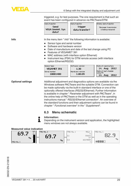
triggered, e.g. for test purposes. The one requirement is that such an eventhasbeenconfiguredinadvanceviaPACTware/DTM.
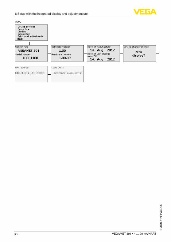
In the menu item " Info" the following information is available:
• Sensor type and serial number• Software and hardware version• Date of manufacture and date of the last change using PC• Features of VEGAMET 391• MAC address (with interface option Ethernet)• Instrument key (PSK) for DTM remote access (with interface
option Ethernet/RS232)
Additional adjustment and diagnostics options are available via the Windows software PACTware and the suitable DTM. Connection can be made optionally via the built-in standard interface or one of the optionallyofferedinterfaces(RS232/Ethernet).Furtherinformationis available in chapter " Parameter adjustment with PACTware", in the online help of PACTware or the DTM as well as in the operating instructions manual " RS232/Ethernet connection". An overview of the standard functions and their adjustment options can be found in chapter " Functional overview" in the " Supplement".
6.3 Menu schematicInformation:Depending on the instrument version and application, the highlighted menu windows are not always available.
Measured value indication
Info
Optional settings

30
6 Setup with the integrated display and adjustment unit
VEGAMET 391 • 4 … 20 mA/HART
36032-EN-210818
Setup assistant
Device settings

31
6 Setup with the integrated display and adjustment unit
VEGAMET 391 • 4 … 20 mA/HART
3603
2-EN
-210
818
Measurement loop - Input
Meas. loop - Parameter
Meas. loop - Adjustment

32
6 Setup with the integrated display and adjustment unit
VEGAMET 391 • 4 … 20 mA/HART
36032-EN-210818
Meas. loop - Damping
Meas. loop - Linearization curve
Meas. loop - Scaling
Meas. loop - Meas. loop TAG

33
6 Setup with the integrated display and adjustment unit
VEGAMET 391 • 4 … 20 mA/HART
3603
2-EN
-210
818
Meas. loop - Outputs - Relay
Meas. loop - Outputs - Current output
Display

34
6 Setup with the integrated display and adjustment unit
VEGAMET 391 • 4 … 20 mA/HART
36032-EN-210818
Diagnostics
Additional adjustments - Simulation
Additional settings - Reset

35
6 Setup with the integrated display and adjustment unit
VEGAMET 391 • 4 … 20 mA/HART
3603
2-EN
-210
818
Additional adjustments - Access protection - PIN
Additional adjustments - Change sensor address
Additional settings - Data transmission (only with option RS232/Ethernet interface)
36
6 Setup with the integrated display and adjustment unit
VEGAMET 391 • 4 … 20 mA/HART
36032-EN-210818
Info

37
7 Setup with PACTware
VEGAMET 391 • 4 … 20 mA/HART
3603
2-EN
-210
818
7 Setup with PACTware
7.1 Connect the PCFor a brief connection to the PC, for example for parameter adjust-ment, you should use the USB interface. The required connection socket is on the lower side of all instrument versions. Keep in mind that correct functioning of the USB interface is only guaranteed in the (limited) temperature range of 0 … 60 °C.
Note:The connection via USB requires a driver. First install the driver before connecting VEGAMET 391 to the PC.
The required USB driver is included on the CD " DTM Collection". You should always use the latest version to ensure support of all instru-ment functions. The system requirements for operation correspond to those of the " DTM Collection" or of PACTware. During installation of the driver package " DTM for Communica-tion", the suitable instrument driver is installed automatically. When VEGAMET 391 is connected, the driver installation is completed autonomously and is ready for operation without a restart.
1
3
2
Fig. 8: Connection of the PC via USB1 USB interface of the PC2 Mini-USB connection cable (in the scope of delivery)3 USB interface of VEGAMET 391
With the Ethernet interface, the instrument can be connected directly to an existing PC network. Any standard patch cable can be used. A cross-over cable must be used when connecting the instrument directly to the PC. To reduce EMC interferences, the supplied split fer-rite should be connected to the Ethernet cable. Each instrument can then be accessed from anywhere in the network by an unique Host name or its own IP address. The parameter adjustment of the instru-ment via PACTware and DTM can be carried out from any PC. The measured values can be made available to individual users within the company network as HTML chart. As an alternative, the independent, time or event-controlled transmission of measured values via e-mail is also possible. The measured values can also be called up via a visualisation software.
Note:To contact the instrument, the IP address or the Host name must be known.Youcanfindthisinformationunderthemenuitem"Device settings". If you modify these entries, the instrument has to be restarted afterwards. Then the instrument can be reached from eve-
Connection of the PC via USB
Connection of the PC via Ethernet

38
7 Setup with PACTware
VEGAMET 391 • 4 … 20 mA/HART
36032-EN-210818
rywhere in the network via its IP address or Host name. These speci-ficationsmustalsobeenteredintheDTM(seechapter"Parameter adjustment with PACTware"). If the encrypted DTM remote access is activated in the controller, the instrument key (PSK) must be entered duringthefirstconnection.Thiskeycanbereadoutviatheon-siteadjustment in the info menu of the controller.
13 2
Fig. 9: Connection of the PC via Ethernet1 Ethernet interface of the PC2 Ethernet connection cable (Cross-Over cable)3 Ethernet interface
The RS232 interface is particularly suitable for simple modem con-nection. External analog, ISDN and GSM modems with standard interface can be used. The necessary RS232 modem connection cable is included with the delivery. To reduce EMC interference, you should mount the supplied ferrite bead on the RS232 modem con-nection cable. Via a visualisation software, measured values can be retrieved remotely and further processed. Alternatively, autonomous time or event controlled transmission of measured values via e-mail is also possible. Remote parameter adjustment of the instrument and the connected sensors is also possible with PACTware.
3
12
Fig. 10: Connection of the modem via RS2321 Analogue, ISDN or GSM modem with RS232 interface2 RS232 modem connection cable (in the scope of delivery)3 RS232 interface (RJ45 plug connection)
Via the RS232 interface, direct parameter adjustment and measured value retrieval from the instrument can be carried out with PACTware. Use the RS232 modem connection cable supplied with the instru-ment and an additionally connected null modem cable (e.g. article no. LOG571.17347). To reduce EMC interference, you should mount the supplied ferrite bead on the RS232 modem connection cable.
Connection of the modem via RS232
Connection of the PC via RS232

39
7 Setup with PACTware
VEGAMET 391 • 4 … 20 mA/HART
3603
2-EN
-210
818
If there is no RS232 interface available on the PC or if it is already occupied, you can also use a USB-RS232 adapter (e.g. article no. 2.26900).
34 12
Fig. 11: Connection of the PC via RS2321 RS232 interface of the PC2 RS232 interlink cable (article no. LOG571.17347)3 RS232 modem connection cable (in the scope of delivery)4 RS232 interface (RJ45 plug connection)
5 4 3 2 1
68 79
1 8
21 3
RXD
CTS
TXD
DTR
GND
RTS
4
2
3
1
5
6
2
8
3
4
5
7
Fig. 12: Connection assignment of the RS232 modem connection cable1 Name of the interface cable2 Assignment of the RJ45 plug (view of contact side)3 Assignment of the RS232 plug (view of soldering side)
7.2 Parameter adjustment with PACTwareAs an alternative to the integrated display and adjustment unit, the adjustment can be also carried out via a Windows PC. For this, the configurationsoftwarePACTwareandasuitableinstrumentdriver(DTM) according to the FDT standard are required. The current PACT-ware version as well as all available DTMs are compiled in a DTM Collection. Furthermore, the DTMs can be integrated into other frame applications compliant with the FDT standard.
Assignment RS232 mo-dem connection cable
Prerequisites
40
7 Setup with PACTware
VEGAMET 391 • 4 … 20 mA/HART
36032-EN-210818
Note:To ensure that all instrument functions are supported, you should always use the latest DTM Collection. Furthermore, not all described functionsareincludedinolderfirmwareversions.Youcandownloadthe latest instrument software from our homepage. A description of the update procedure is also available in the Internet.
Further setup steps are described in the operating instructions manual " DTM Collection/PACTware" attached to each DTM Collec-tion and which can also be downloaded from the Internet. A detailed description is available in the online help of PACTware and the DTMs as well as in the supplementary instructions manual " RS232/Ethernet connection".
To contact the instrument, the IP address or the Host name must be known.Youcanfindthisinformationunderthemenuitem"Device settings".Iftheprojectsetupiscarriedoutwithoutassistant(offlinemode), IP address and subnet mask or the Host name must be entered in the DTM. Click in the project window with the right mouse key on the Ethernet DTM and choose " Add. functions - Modify DTM addresses". If the encrypted DTM remote access is activated in the controller,theinstrumentkey(PSK)mustbeenteredduringthefirstconnection. This key can be read out via the on-site adjustment in the info menu of the controller.
All device DTMs are available as a free-of-charge standard version and as a full version that must be purchased. In the standard version, all functions for complete setup are already included. An assistant for simpleprojectconfigurationsimplifiestheadjustmentconsiderably.Saving/printing the project as well as import/export functions are also part of the standard version.In the full version there is also an extended print function for complete project documentation as well as a save function for measured value and echo curves. In addition, there is a tank calculation program as well as a multiviewer for display and analysis of the saved measured value and echo curves.
7.3 Setup web server/e-mail, remote enquirySetup and application examples of the web server, the e-mail func-tions and the visualisation VEGA Inventory System are provided in the supplementary instructions " RS232/Ethernet connection". The connection via Modbus-TCP or ASCII protocol is described in the supplementary instruction manual " Modbus-TCP, ASCII protocol". Both supplementary instruction manuals are included with every instrument with RS232 or Ethernet interface.
Connection via Ethernet
Standard/Full version

41
8 Application examples
VEGAMET 391 • 4 … 20 mA/HART
3603
2-EN
-210
818
8 Application examples
8.1 Level measurement in a horizontal cylindrical tankwithoverfillprotection/dryrunprotection
The level is detected by a sensor and transmitted to the controller by means of a 4 … 20 mA signal. Here, an adjustment is carried out, converting the input value delivered by the sensor into a percentage value.Due to the geometrical form of the horizontal cylindrical tank, the vessel volume does not increase linearly with the level. This can be compensated by selecting the linearisation curve integrated in the in-strument. This curve states the relationship between percentage level and vessel volume. If the level is to be displayed in litres, a scaling must also be carried out. For this purpose, the linearised percentage value is converted into a volume, for example with the unit litre.Filling and emptying are controlled via relay 1 and 2 which are inte-gratedinthecontroller.Duringfilling,relaymode"Overfill protection" isset.Therelayisthusswitchedoff(safecurrentlessstate)whenthemax. level is exceeded, and switched on again when the min. level is underrun(switch-onpoint<switch-offpoint).Duringemptying,mode" Dry run protection"isused.Thisrelayisthusswitchedoffwhenthemin. level is underrun (safe currentless condition), and switched on againwhenthemax.levelisexceeded(switch-onpoint>switch-offpoint).
Rel. 1 Rel. 2
Rel. 1: 90%
Rel. 2: 5%
100%
0%
Fig. 13: Example of level measurement, horizontal cylindrical tank
A horizontal cylindrical tank has a capacity of 10000 litres. The meas-urement is carried out with a level sensor operating according to the guidedmicrowaveprinciple.Thefillingbyatankcariscontrolledviarelay1andavalve(overfillprotection).Thedischargeiscarriedoutvia a pump and is controlled by relay 2 (dry run protection). The max. volume should be at 90 % level, this means 9538 litres with a stand-
Functional principle
Example

42
8 Application examples
VEGAMET 391 • 4 … 20 mA/HART
36032-EN-210818
ard vessel (according to sounding table). The min. level should be set to 5 %, this corresponds to 181 litres. The volume is to be displayed in litres.
Carry out the adjustment in the controller as described in chapter " Setup steps". No further adjustment may be carried out in the sensor itself.Forthemax.adjustment,fillthevesseluptotherequestedmax.level and accept the actually measured value. If this is not possible, the corresponding current value can also be entered. For the min. adjustment, empty the vessel down to the min. level or enter the cor-responding current value.
To display the percentage level correctly, select under " Measurement loop - Linearization curve" the entry " Horiz. cylindrical tank".
To display the volume in litres, you have to enter " Volume" as the unit in litres under " Measurement loop - Scaling". The allocation is then carried out, in this example 100 % ≙ 10000 litres and 0 % ≙ 0 litres.
Percent is selected as reference value for the relays. The mode of relay1issettooverfillprotection,relay2mustbeactivatedandgetsmodedryrunprotection.Toensurethatthepumpswitchesoffincaseof failure, the reaction in case of failure should be set to switching status OFF. The switching points are set as follows:
• Relay 1:Switch-offpoint90%,switch-onpoint85%• Relay 2:Switch-offpoint5%,switch-onpoint10%
Information:Theswitch-onandswitch-offpointoftherelaysmustnotbesettothesame switching point because this would cause a continuous switch-ingonandoffwhenthisthresholdisreached.Toavoidthiseffectalsowithfluctuatingmediumsurfaces,itisagoodideatosetadifference(hysteresis) of 5 % between the switching points.
8.2 Pump control 1/2 (run time controlled)
Pump control 1/2 is used to control several pumps with the same function, in dependence on their respective elapsed running times. The pump with the shortest elapsed running time is switched on andthepumpwiththelongestrunningtimeswitchedoff.Incaseofincreased pumping requirement, all pumps can also run at the same time, in dependence on the entered switching points. This measure achieves an even utilization of the pumps and increases operational reliability.Allrelayswithactivatedpumpcontrolareswitchedonoroffdepend-ing on the accumulated operating time. The controller selects the relay with the shortest elapsed operating time when the switch-on point is reached and the relay with the longest elapsed operating time whentheswitch-offpointisreached.Pump fault messages can also be processed via the digital inputs.Thispumpcontrolsystemofferstwodifferentoptions:
Adjustment
Linearisation
Scaling
Relay
Functional principle

43
8 Application examples
VEGAMET 391 • 4 … 20 mA/HART
3603
2-EN
-210
818
• Pump control 1: The upper switching point determines the switch-offpointfortherelay,whereasthelowerswitchingpointdetermines the switch-on point
• Pump control 2: The upper switching point determines the switch-on point for the relay, whereas the lower switching point determinestheswitch-offpoint
Two pumps should empty the vessel when a certain level is reached. At80%filling,thepumpwiththeshortestelapsedrunningtimeshould switch on. If the level nevertheless increases, a second pump shouldswitchonat90%.Bothpumpsshouldswitchoffagainat10%filling.
Select in the DTM navigation section the menu items " Meas. loop - Outputs - Relay".
• Set mode " Pump control 2" for relay 1 and 2 with the option " Sequenced operation".
• Entertheswitchingpointsfortheaffectedrelaysasfollows: – Relay 1 upper switching point = 80.0 % – Relay 1 lower switching point = 10.0 % – Relay 2 upper switching point = 90.0 % – Relay 2 lower switching point = 10.0 %
The function of pump control 2 is shown in detail in the following dia-gram. The previously described example is used as a basis.
Rel. 1: 80% On
On
Off
Off
On
Rel. 2: 90% On
Rel. 1, 2: 10% Off
10 30 20 20 15 t [h]5
Rel. 1
Rel. 2
Fig. 14: Example of pump control 2
When pump control is activated, the assigned relays and possible pump malfunctions are also displayed in the measured value indica-tion.
Example
Setup
Display indication

44
8 Application examples
VEGAMET 391 • 4 … 20 mA/HART
36032-EN-210818
1 2 3 4 5
Fig. 15: Display indication of a pump control1 Symbol, activated pump control2 Relay 1 is assigned to the pump control3 Relay 2 is assigned to the pump control and signals failure4 Relay 3 is assigned to the pump control5 Relay 4 is free i.e. not assigned to the pump control
Pump control 2/4 with dry weather pump is used to protect e.g. rainretentionbasinswithdifferentsizedpumpsagainstoverfilling.Normally (in fair weather), a pump with low capacity (dry weather pump)issufficienttomaintainthelevelintheretentionbasinatasafelevel(Hi-Level).Ifheavyrainfallcausesanincreasedinflow,thefair weather pump can no longer maintain the level. In such cases, a larger pump is switched on when the HiHi level is exceeded and the dryweatherpumpisswitchedoff.Thelargepumpthenremainsinoperationuntiltheswitch-offpointisreached.Ifthelevelrisesagain,thedryweatherpumpswitchesbackonfirst.There is also the possibility of using multiple large pumps in alternat-ing mode. The algorithm for the switching function is then determined by the pump control mode.
Fig. 16: Example of a pump control with option " Dry weather pump"
Option Dry weather pump
45
8 Application examples
VEGAMET 391 • 4 … 20 mA/HART
3603
2-EN
-210
818
Note:If the option " Dry weather pump" is activated, only the mode " Alter-nating pump operation" will be available, i.e. only one pump at a time is in operation.
Thepumpcontrolsystemoffersthepossibilitytochoosebetweensequenced and alternating pump operation:
• Sequenced operation: Depending on the switching points, all pumps are switched on one after the other, i.e. the max. number of pumps that can be switched on corresponds to the number of assigned relays
• Alternating pump operation: Independent of the switching point, only one pump at a time is switched on
If the level has not changed over a longer period, the same pump would always remain switched on. Via the parameter " Switchover time", a time can be preset which, after it is elapsed, forces a switcho-ver of the pump. Which pump is switched on depends on the selected pump mode. If all pumps are already switched on, the pump remains switched on. This function can only be set with a PC and DTM.
Note:If the pump is already switched on when the forced switchover is activated,thetimerisnotstarted.Onlyafterthepumpisswitchedoffandonagainwillthetimerstart.Ifaswitch-offdelayisset,itwillnotbe taken into account, i.e. the switchover is carried out exactly after the preset time for the forced switchover expires. A preset switch-on delay, however, is taken into account, i.e. the forced switchover to another pump is carried out after the preset time expires. Before the newly selected pump switches on, the preset switch-on delay for this pump must have expired.
With a pump control, there is also the possibility of switching on pump monitoring. For this purpose, a feedback signal is required on the re-spective digital input. The digital inputs are assigned 1:1 to the relays. Digital input 1 acts on relay 1, etc.If the pump monitoring for a relay was switched on, a timer is started when the relay is switched on (time allowance with parameter " Report time"). If the checkback signal comes from the pump on the respectivedigitalinputwithinthedefinedreporttime,thepumprelayremainsenergized,otherwisetherelayisimmediatelyswitchedoffandafaultsignaloutputted.Afaultsignalandaswitchingoffoftherelay is carried out even if the relay is already switched on and the pump checkback signal changes during the running time of the pump. Inaddition,aswitched-offrelayofthepumpcontrolislookedforandswitched on instead of the faulted relay. A Low signal on the digital input is evaluated as a pump error signal. The fault signal is cancelled when the signal on the digital input changes to "Good" or when it is reset via the " OK" key and selec-tion of the menu item " Acknowledge failure". If the fault message is reset via the menu and the pump still signals failure, a fault signal is
Pump control mode
Option, forced switchover
Pump monitoring
46
8 Application examples
VEGAMET 391 • 4 … 20 mA/HART
36032-EN-210818
triggered after the enquiry period. The enquiry period is started as described above when the relay is switched on.
Switch-on behaviour of pump control 2Whenthecontrollerisswitchedon,therelaysareatfirstinaswitched-offstatus.Dependingontheactualinputsignalandtheswitched-on period of the individual relays, the following relay switch-ing conditions can occur after the start procedure:
• Input signal is higher than the upper switching point -> Relay with the shortest switched-on period is switched on
• Input signal is between lower and upper switching point -> Relay remainsswitchedoff
• Input signal is smaller than the lower switching point -> Relay remainsswitchedoff
8.3 Pump control 3/4 (sequentially controlled)
Pump control 3/4 is used to control several pumps with the same functionalternatelyandinafixedsequence.Incaseofincreasedpumping requirement, all pumps can also run at the same time, in dependence on the entered switching points. This measure achieves an even utilization of the pumps and increases operational reliability.All relays with activated pump control are not assigned to a certain switchingpointbutareswitchedonandoffalternately.Whenaswitch-on point is reached, the controller selects the relay that is next in the sequence.Whenaswitch-offpointisreached,therelaysareswitchedoffinthesequencetheywereswitchedon.Via the digital inputs, possible fault signals of the pumps can also be evaluated.Youcanfindthedescriptionofthisintheapplicationexam-ple " Pump control 1/2" under " Pump monitoring". Thispumpcontrolsystemofferstwodifferentoptions:
• Pump control 3: The upper switching point determines the switch-offpointfortherelay,whereasthelowerswitchingpointdeter-mines the switch-on point
• Pump control 4: The upper switching point determines the switch-on point for the relay, whereas the lower switching point deter-minestheswitch-offpoint
The sequence cannot be changed, the relay with the lowest index is switchedonfirst,thentherelaywiththenexthigherindex.Aftertherelay with the highest index, the relay with the lowest index follows, for example Rel. 1 -> Rel. 2 -> Rel. 3 -> Rel. 4 -> Rel. 1 -> Rel. 2 … The sequence applies only to those relays assigned to the pump control.
In a waste water disposal system, a sump should be pumped empty when a certain level is reached. Three pumps are available for this. At 60 % level, pump 1 should run until the level has fallen below 10 %. If the 60 % point is exceeded again, the same task is transferred to pump 2. In the third cycle, pump 3 is activated; after that, pump 1 again. If the level continues to rise despite operation of a pump, an additional pump switched on when the level exceeds the 75 % switch-
Functional principle
Example
47
8 Application examples
VEGAMET 391 • 4 … 20 mA/HART
3603
2-EN
-210
818
ingpoint.Andifthelevelstillrisesfurtherduetoextremeinflowandexceeds the 90 % limit, pump 3 is also switched on.
Select in the DTM navigation section the menu items " Meas. loop - Outputs - Relay".
• Set mode " Pump control 4" for relays 1 … 3 with option " Sequenced operation".
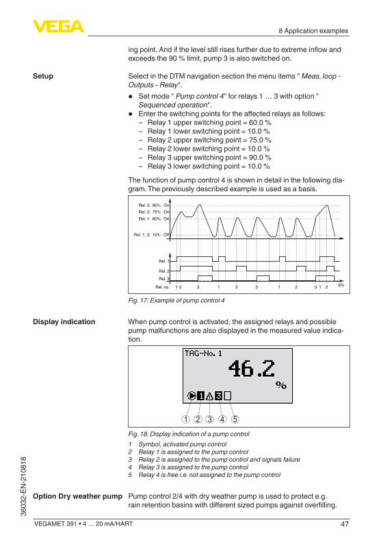
• Entertheswitchingpointsfortheaffectedrelaysasfollows: – Relay 1 upper switching point = 60.0 % – Relay 1 lower switching point = 10.0 % – Relay 2 upper switching point = 75.0 % – Relay 2 lower switching point = 10.0 % – Relay 3 upper switching point = 90.0 % – Relay 3 lower switching point = 10.0 %
The function of pump control 4 is shown in detail in the following dia-gram. The previously described example is used as a basis.
Rel. 1: 60% On
Rel. 1..3: 10% Off
Rel. 2: 75% OnRel. 3: 90% On
t(h)Rel. 3
Rel. no.
Rel. 2
1 2 3 1 2 3 1 2 3 1 2
Rel. 1
Fig. 17: Example of pump control 4
When pump control is activated, the assigned relays and possible pump malfunctions are also displayed in the measured value indica-tion.
1 2 3 4 5
Fig. 18: Display indication of a pump control1 Symbol, activated pump control2 Relay 1 is assigned to the pump control3 Relay 2 is assigned to the pump control and signals failure4 Relay 3 is assigned to the pump control5 Relay 4 is free i.e. not assigned to the pump control
Pump control 2/4 with dry weather pump is used to protect e.g. rainretentionbasinswithdifferentsizedpumpsagainstoverfilling.
Setup
Display indication
Option Dry weather pump

48
8 Application examples
VEGAMET 391 • 4 … 20 mA/HART
36032-EN-210818
Normally (in fair weather), a pump with low capacity (dry weather pump)issufficienttomaintainthelevelintheretentionbasinatasafelevel(Hi-Level).Ifheavyrainfallcausesanincreasedinflow,thefair weather pump can no longer maintain the level. In such cases, a larger pump is switched on when the HiHi level is exceeded and the dryweatherpumpisswitchedoff.Thelargepumpthenremainsinoperationuntiltheswitch-offpointisreached.Ifthelevelrisesagain,thedryweatherpumpswitchesbackonfirst.There is also the possibility of using multiple large pumps in alternat-ing mode. The algorithm for the switching function is then determined by the pump control mode.
Fig. 19: Example of a pump control with option " Dry weather pump"
Note:If the option " Dry weather pump" is activated, only the mode " Alter-nating pump operation" will be available, i.e. only one pump at a time is in operation.
Thepumpcontrolsystemoffersthepossibilitytochoosebetweensequenced and alternating pump operation:
• Sequenced operation: Depending on the switching points, all pumps are switched on one after the other, i.e. the max. number of pumps that can be switched on corresponds to the number of assigned relays
• Alternating pump operation: Independent of the switching point, only one pump at a time is switched on
If the level does not change over a longer period of time, the same pump would remain switched on. Via the parameter " Changeover time", a time period can be preset, after which a forced changeover of the pump is carried out. This function is described under pump control 1/2.
Pump control mode
Option, forced switchover
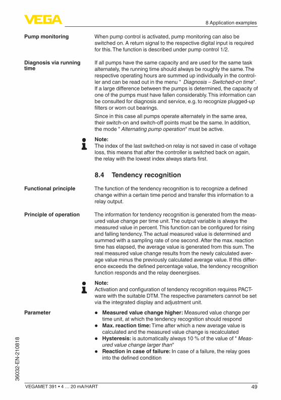
49
8 Application examples
VEGAMET 391 • 4 … 20 mA/HART
3603
2-EN
-210
818
When pump control is activated, pump monitoring can also be switched on. A return signal to the respective digital input is required for this. The function is described under pump control 1/2.
If all pumps have the same capacity and are used for the same task alternately, the running time should always be roughly the same. The respective operating hours are summed up individually in the control-ler and can be read out in the menu " Diagnosis – Switched-on time". Ifalargedifferencebetweenthepumpsisdetermined,thecapacityofone of the pumps must have fallen considerably. This information can be consulted for diagnosis and service, e.g. to recognize plugged-up filtersorwornoutbearings.Since in this case all pumps operate alternately in the same area, theirswitch-onandswitch-offpointsmustbethesame.Inaddition,the mode " Alternating pump operation" must be active.
Note:The index of the last switched-on relay is not saved in case of voltage loss, this means that after the controller is switched back on again, therelaywiththelowestindexalwaysstartsfirst.
8.4 Tendency recognition
Thefunctionofthetendencyrecognitionistorecognizeadefinedchange within a certain time period and transfer this information to a relay output.
The information for tendency recognition is generated from the meas-ured value change per time unit. The output variable is always the measuredvalueinpercent.Thisfunctioncanbeconfiguredforrisingand falling tendency. The actual measured value is determined and summed with a sampling rate of one second. After the max. reaction time has elapsed, the average value is generated from this sum. The real measured value change results from the newly calculated aver-agevalueminusthepreviouslycalculatedaveragevalue.Ifthisdiffer-enceexceedsthedefinedpercentagevalue,thetendencyrecognitionfunction responds and the relay deenergises.
Note:ActivationandconfigurationoftendencyrecognitionrequiresPACT-ware with the suitable DTM. The respective parameters cannot be set via the integrated display and adjustment unit.
• Measured value change higher: Measured value change per time unit, at which the tendency recognition should respond
• Max. reaction time: Time after which a new average value is calculated and the measured value change is recalculated
• Hysteresis: is automatically always 10 % of the value of " Meas-ured value change larger than"
• Reaction in case of failure: In case of a failure, the relay goes intothedefinedcondition
Pump monitoring
Diagnosis via running time
Functional principle
Principle of operation
Parameter

50
8 Application examples
VEGAMET 391 • 4 … 20 mA/HART
36032-EN-210818
Note:After a switching on or a fault occurs, two complete cycles must elapsebeforeameasuredvaluedifferencecanbecalculatedandatendency output.
The level in a basin is to be monitored for rising tendency. If the rise is higher than 25 % per minute, an additional emptying pump should be switched on. The max. reaction time should be one minute. In case of afault,thepumpshouldbeswitchedoff.
Select in the DTM navigation section the menu items " Meas. loop - Outputs - Relay".
• E.g. set for relay 1 the mode " Rising tendency" • Select under " Reaction in case of failure" the option " Switching
condition off" • Enterthefollowingvaluesintotheparameterfields:
– Measured value more than 25 %/min. – Max. reaction time 1 min.
The function of the tendency recognition is shown in detail in the fol-lowing diagram. The previously described example is used as a basis.
t
t m
t m
t m
t m
120 180 240ON OFF
60 [sec]
1 2 3 4
5
... ...
...
...
100
75 50
25
0
%
...
Fig. 20: Example of tendency recognition1 Old average value = 25 %, new average value = 25 %
Difference < 25 % -> Relay ON2 Old average value = 25 %, new average value = 37.5 %
Difference < 25 % -> Relay ON3 Old average value = 37.5 %, new average value = 62.5 %
Difference = 25 % -> Relay OFF4 Old average value = 62.5 %, new average value = 75 %
Difference < 25 % -> Relay ON5 tm -> max. reaction time
8.5 Flow measurement
Forflowmeasurementinopenflumes,aconstrictionorstandardflumemustbeused.Dependingontheflowvolume,thisconstrictiongeneratesacertainlevelofbackwater.Theflowratecanbedeter-minedfromtheheightofthisbackwater.Theflowvolumeisoutputtedvia an appropriate number of pulses on the relay or current output and can thus be further processed by connected downstream instruments.
Example
Setup
Functional principle

51
8 Application examples
VEGAMET 391 • 4 … 20 mA/HART
3603
2-EN
-210
818
Thereisalsotheoptionofsumminguptheflowvolumebymeansoftotalizers, the result is available on the display and as PC/DCS value.
Everyflumegeneratesadifferentlevelofbackwaterdependingonitstypeandversion.Thespecificationsofthefollowingflumesareavail-able in the instrument:
• Palmer-Bowlusflume• Venturiflume,trapezoidalweir,rectangularoverfall• Triangular overfall, V-notch
SetupTheconfigurationoftheflowmeasurementlooprequiresPACTwarewiththesuitableDTMs.Theexamplereferstoaflowmeasurementwith a radar sensor. The following setup steps must be carried out:
• Selection of the parameter "Flow"• Carry out adjustment• Selectflume(linearization)• Set scaling• Set parameters of pulse outputs• Parameter adjustment of the totalizer
Select in the DTM window " Parameter" the option " Flow" with the requested unit of measurement.
Min. adjustment: Enter the suitable value for 0 %, i.e. the distance fromthesensortothemediumwhenthereisnoflow.Inthefollowingexample this is 1.40 m.Max. adjustment: Enter the suitable value for 100 %, i.e. the distance fromthesensortothemediumwhenthereismaximumflowrate.Thisis 0.80 m in the following example.
100% 0,80m (d)= 400m3/h=
0% 1,40m (d)= 0m3/h=
Fig. 21: Adjustment of flow measurement with V-notch
Select in the DTM window " Linearization" the option " Flow" and then theflumetypeused(V-notchintheaboveexample).
Select in the DTM window " Scaling" under " Parameter" the option " Flow".Thentheallocationofvaluesmustbecarriedout,i.e.aflowvolume is assigned to the 0 and 100 % values respectively. In the last
Flume
Parameter - Flow
Adjustment
Linearisation curve
Scaling

52
8 Application examples
VEGAMET 391 • 4 … 20 mA/HART
36032-EN-210818
step, select the requested meas. unit. For the above example: 0 % = 0 and 100 % = 400, meas. unit m³/h.
First of all decide if you want to use a relay and/or a current output. In the DTM window " Outputs" you can use any of the three outputs as long as these are not yet used for other tasks. Then select under " Mode" (relay) or " Output characteristics" (current output) the option " Flow volume pulse" or " Sampling pulse". Enter under " Pulse output all"theflowvolumeafterwhichapulseshouldbe outputted (e.g. 400 m³ corresponds to one pulse per hour with a flowvolumeof400m³/h).In mode " Sampling pulse" an additional pulse is output after a definedtime.Thismeansthatatimerisstartedaftereachpulse,afterwhich another pulse is output. This only applies if a pulse was not alreadyoutputaftertheflowvolumewasexceeded.Duetosludgeatthebottomoftheflume,itcanhappenthatthemin.level value originally set can no longer be reached. The result is that smallflowquantitieswillbecontinuouslydetecteddespitethe"emp-ty"flume.Theoption"Min. flow volume suppression"offerstheoptionofsuppressingmeasuredflowvolumesbelowacertainpercentagevalueforflowvolumedetection.
Ifflowmeasurementhasbeensetup,theflowvaluecanalsobesummedupanddisplayedasflowvolume.Theflowvolumecanbedisplayed in its own measured value indication in the highest menu level. The following parameters must be adjusted for the totalizers:
• Measuring unit: Selection of the unit the totalizer uses for adding.• Display format: Selection of the display format (number of decimal
positions of the counter)
Information:The totalizers can be reset in the menu " Additional adjustments" - " Reset". As an alternative, the counter can also be reset in the meas-ured value indication by pressing " OK" and " Reset".
Outputs
Totalizer

53
9 Diagnostics and servicing
VEGAMET 391 • 4 … 20 mA/HART
3603
2-EN
-210
818
9 Diagnostics and servicing
9.1 MaintenanceIf the device is used properly, no special maintenance is required in normal operation.
The cleaning helps that the type label and markings on the instrument are visible.Take note of the following:
• Use only cleaning agents which do not corrode the housings, type label and seals
• Use only cleaning methods corresponding to the housing protec-tion rating
9.2 Rectify faultsThe operator of the system is responsible for taking suitable meas-ures to rectify faults.
Thedeviceoffersmaximumreliability.Nevertheless,faultscanoccurduring operation. These may be caused by the following, e.g.:
• Measured value from sensor not correct• Voltage supply• Interference in the cables
Thefirstmeasurestobetakenaretochecktheinputandoutputsignal as well as to evaluate the error messages via the display. The procedure is described below. Further comprehensive diagnostics can be carried out on a PC with PACTware and the suitable DTM. In many cases, the causes can be determined in this way and faults rectified.
Depending on the reason for the fault and the measures taken, the steps described in chapter " Setup" must be carried out again or must be checked for plausibility and completeness.
Should these measures not be successful, please call in urgent cases the VEGA service hotline under the phone no. +49 1805 858550. Thehotlineismanned7daysaweekround-the-clock.Sinceweofferthis service worldwide, the support is only available in the English language. The service is free, only standard call charges are incurred.
9.3 Diagnosis, fault messagesWhen the connected sensor is provided with a self-monitoring according to NE 107, the probably occurring status messages are passed on and output on the VEGAMET indication. Requirement is thattheHARTinputoftheVEGAMETisactivated.Youcanfindfurtherinformation in the operating instructions manual of the sensor.
Maintenance
Cleaning
Reaction when malfunc-tion occurs
Causes of malfunction
Faultrectification
Reaction after fault recti-fication
24 hour service hotline
Status messages

54
9 Diagnostics and servicing
VEGAMET 391 • 4 … 20 mA/HART
36032-EN-210818
41 2 3Fig. 22: Pictographs of the status messages1 Failure2 Function check3 Out of specification4 Maintenance required
The controller and the connected sensors are permanently monitored during operation and the values entered during parameter adjust-ment are checked for plausibility. If irregularities occur or in case of incorrect parameter adjustment, a fault signal is triggered. In case of an instrument defect or line break/shortcircuit, a fault signal is also triggered.The fault indication lights up in case of failure and the current output aswellastherelaysreactaccordingtotheconfiguredfaultmode.Ifthefailsaferelaywasconfigured,itwilldeenergize.Inaddition,oneofthe following error messages is outputted on the display.
Error code Cause Rectification
E003 CRC error (error with self-check)
Carry out a resetSend instrument for repair
E007 Sensor type not compatible
Search for sensor again and allocate under " Measuring point - Input"
E008 Sensor not found Check connection of the sensorCheck HART address of the sensor
E013 Sensor signals error, no valid measured value
Check sensor parameter adjustmentSend sensor for repair
E014 Sensor cur-rent > 21 mA or short-circuit
Check sensor, e.g. on fault signalRemove short-circuit
E015 Sensor in boot phaseSensor current < 3.6 mA or line break
Check sensor, e.g. on fault signalRemove line breakCheck connection of the sensor
E016 Empty/full adjustment re-versed
Carry out a fresh adjustment
E017 Adjustment span too small
Carry out a fresh adjustment and increase the distance between min. and max. adjustment
E021 Scaling span too small
Carry out a fresh scaling, increase the distance between min. and max. scaling.
Fault message

55
9 Diagnostics and servicing
VEGAMET 391 • 4 … 20 mA/HART
3603
2-EN
-210
818
Error code Cause Rectification
E030 Sensor in boot phaseMeasured value not valid
Check sensor parameter adjustment
E034 EEPROM CRC error
SwitchtheinstrumentoffandonCarry out a resetSend instrument for repair
E035 ROM CRC error SwitchtheinstrumentoffandonCarry out a resetSend instrument for repair
E036 Instrument software not ex-ecutable (during software update and after failed update)
WaituntilsoftwareupdateisfinishedCarry out another software update
E053 Sensor measur-ing range is not read correctly
Communication error: Check sensor cable and shielding
E062 Pulse priority too small
Increase under " Output" the entry " Pulse output all" so that max. one pulse per second is output
E110 Relay switching points too close together
Increasethedifferencebetweenthetworelay switching points
E111 Relay switching points inter-changed
Change relay switching points for " On/Off"
E115 Several relays are assignef to the pump control which are not set to the same fail-ure mode
All relays which are assigned to the pump control must be set to the same failure mode
E116 Several relays that are not con-figuredwiththesame mode are assigned to the pump control
All relays which are assigned to the pump control must be set to the same mode
E117 A monitored pump signals failure
Check the faulty pump. For acknowl-edgement, carry out the reset " Failure relay 1 … 4" or switch the instrument OFF and ON again
9.4 How to proceed if a repair is necessaryYoucanfindaninstrumentreturnformaswellasdetailedinformationabout the procedure in the download area of our homepage. By doing this you help us carry out the repair quickly and without having to call back for needed information.

56
9 Diagnostics and servicing
VEGAMET 391 • 4 … 20 mA/HART
36032-EN-210818
In case of repair, proceed as follows:
• Printandfilloutoneformperinstrument• Clean the instrument and pack it damage-proof• Attach the completed form and, if need be, also a safety data
sheet outside on the packaging• Ask the agency serving you to get the address for the return ship-
ment.Youcanfindtheagencyonourhomepage.
57
10 Dismount
VEGAMET 391 • 4 … 20 mA/HART
3603
2-EN
-210
818
10 Dismount
10.1 Dismounting stepsTake note of chapters " Mounting" and " Connecting to voltage sup-ply" and carry out the listed steps in reverse order.
10.2 DisposalThe device is made of recyclable materials. For this reason, it should be disposed of by a specialist recycling company. Observe the ap-plicable national regulations.

58
11Certificatesandapprovals
VEGAMET 391 • 4 … 20 mA/HART
36032-EN-210818
11 Certificatesandapprovals
11.1 Approvals for Ex areasApproved versions for use in hazardous areas are available or in preparation for the device series.Youcanfindtherelevantdocumentsonourhomepage.
11.2 ApprovalsasoverfillprotectionApprovedversionsforuseaspartofanoverfillprotectionsystemareavailable or in preparation for this device series.The corresponding approvals can be found on our homepage.
11.3 EU conformityThedevicefulfilsthelegalrequirementsoftheapplicableEUdirec-tives.ByaffixingtheCEmarking,weconfirmtheconformityoftheinstrument with these directives.The EU conformity declaration can be found on our homepage.
Electromagnetic compatibilityThe instrument is designed for use in an industrial environment. Nevertheless, electromagnetic interference from electrical conductors and radiated emissions must be taken into account, as is usual with a class A instrument according to EN 61326-1. If the instrument is used inadifferentenvironment,itselectromagneticcompatibilitywithotherdevices must be ensured by suitable measures.
11.4 Environment management systemProtection of the environment is one of our most important duties. That is why we have introduced an environment management system with the goal of continuously improving company environmental pro-tection.TheenvironmentmanagementsystemiscertifiedaccordingtoDINENISO14001.Pleasehelpusfulfilthisobligationbyobserv-ing the environmental instructions in chapters " Packaging, transport and storage", " Disposal" of these operating instructions.

59
12 Supplement
VEGAMET 391 • 4 … 20 mA/HART
3603
2-EN
-210
818
12 Supplement
12.1 Technical dataNote for approved instrumentsThe technical data in the respective safety instructions are valid for approved instruments (e.g. with Exapproval).Insomecases,thesedatacandifferfromthedatalistedherein.All approval documents can be downloaded from our homepage.
General dataSeries Instrument for mounting into front panel, switching cabi-
net or housingWeight 620 g (1.367 lbs)Housing materials Valox 357 XUConnection terminals
Ʋ Type of terminal Pluggable spring-loaded terminal with coding Ʋ Max. wire cross-section 2.5 mm² (AWG 14)
Voltage supplyOperating voltage non-Ex version
Ʋ Nominal voltage AC 24 … 230 V (-15 %, +10 %) 50/60 Hz Ʋ Nominal voltage DC 24 … 230 V (-15 %, +10 %)
Operating voltage Ex version Ʋ Nominal voltage AC 24 … 230 V (-15 %, +10 %) 50/60 Hz Ʋ Nominal voltage DC 24 … 65 V (-15 %, +10 %)
Max. power consumption 7 VA; 3 W
Sensor inputNumber of sensors 1 x 4 … 20 mA (HART)Type of input (selectable)
Ʋ Active input Sensor supply through VEGAMET 391 Ʋ Passive input Sensor has an own voltage supply
Measured value transmission (switchable with RS232/Ethernet interface option) Ʋ 4 … 20 mA analogue for 4 … 20 mA sensors Ʋ HART protocol digital for HART sensors
Deviation Ʋ Accuracy ±20 µA (0.1 % of 20 mA)
Terminal voltage Ʋ Non-Ex version 28.5 … 22 V at 4 … 20 mA Ʋ Ex version 19 … 14.5 V at 4 … 20 mA
Current limitation approx. 26 mAInternal resistance mode passive <250ΩDetection line break ≤3.6mA

60
12 Supplement
VEGAMET 391 • 4 … 20 mA/HART
36032-EN-210818
Detection shortcircuit ≥21mAAdjustment range 4 … 20 mA sensor
Ʋ Empty adjustment 2.4 … 21.6 mA Ʋ Full adjustment 2.4 … 21.6 mA Ʋ min. adjustment delta 16 µA
Adjustment range HART sensor Ʋ Adjustment range ± 10 % of sensor measuring range Ʋ min. adjustment delta 0.1 % of sensor measuring range
Connection cable to the sensor two-wire shielded standard cable
Digital inputQuantity 4 x digital inputInput type PassiveSwitching threshold
Ʋ Low -3 … 5 V DC Ʋ High 11 … 30 V DC
Max. input voltage 30 V DCMax. input current 4 mAMax. sampling rate 10 Hz
Relay outputsQuantity 6 x operating relayFunction Switching relay for level, fault signal or pulse relay for
flow/samplingpulseContact Floating spdtContact material AgSnO2, hard gold-platedSwitching voltage min. 10 mV DC, max. 250 V AC/60 V DCSwitching current min. 10 µA DC, max. 3 A AC, 1 A DCBreaking capacity 1) min. 50 mW, max. 500 VA, max. 54 W DCMin. programmable switching hysteresis 0.1 %Mode pulse output
Ʋ Pulse length 350 ms
Current outputQuantity 1 x outputFunction Currentoutputforlevelorflow/samplingpulseRange 0/4 … 20 mA, 20 … 0/4 mAResolution 1 µAMax. load 500ΩFault signal (switch over) 0; < 3.6; 4; 20; 20.5; 22 mA
1) If inductive loads or stronger currents are switched through, the gold plating on the relay contact surface will be permanently damaged. The contact is then no longer suitable for switching low-level signal circuits.

61
12 Supplement
VEGAMET 391 • 4 … 20 mA/HART
3603
2-EN
-210
818
Accuracy Ʋ Standard ±20 µA (0.1 % of 20 mA) Ʋ with EMC interferences ±80 µA (0.4 % of 20 mA)
Temperature error relating to 20 mA 0.005 %/KMode pulse output
Ʋ Voltage pulse 12VDCat20mAwithload600Ω Ʋ Pulse length 200 ms
USB interface 2)
Quantity 1 xPlug connection Mini-B (4-pole)USBspecification 2.0 (Fullspeed)Max. cable length 5 m (196 in)
Ethernet interface (optional)Quantity 1 x, cannot be combined with RS232Data transmission 10/100 MBitPlug connection RJ45Max. cable length 100 m (3937 in)
RS232 interface (optional)Quantity 1 x, cannot be combined with EthernetPlug connection RJ45 (modem connection cable on 9-pole D-SUB in the
scope of delivery)Max. cable length 15 m (590 in)
Clock (only with interface option)Accuracy/Deviation
Ʋ typical 20 ppm (correspond to 10.5 min./year) Ʋ Max. 63 ppm (correspond to 33 min./year)
Power reserve of the lithium battery (Li/MnO2) Ʋ typical 10 years at 20 °C Ʋ Min. 4 years
IndicatorsMeasured value indication
Ʋ Graphic-capable LC display, with lighting
65 x 32 mm, digital and quasianalogue display
Ʋ Max. indicating range -99999 … 99999LED displays
Ʋ Status, operating voltage 1 x LED green Ʋ Status fault signal 1 x LED red
2) Limited temperature range, see ambient conditions

62
12 Supplement
VEGAMET 391 • 4 … 20 mA/HART
36032-EN-210818
Ʋ Status operating relay 1 … 6 6 x LED yellow
AdjustmentAdjustment elements 4 x keys for menu adjustmentPC adjustment PACTware with respective DTM
Ambient conditionsAmbient temperature
Ʋ Instrument in general -20 … +60 °C (-4 … +140 °F) Ʋ USB interface 0 … +60 °C (32 … +140 °F)
Storage and transport temperature -40 … +80 °C (-40 … +176 °F)Relative humidity < 96 %
Electrical protective measuresProtection rating
Ʋ Front IP65 Ʋ Instrument IP20
Overvoltage category (IEC 61010-1) Ʋ up to 2000 m (6562 ft) above sea level II Ʋ up to 5000 m (16404 ft) above sea level
II - Only with connected overvoltage protection
Ʋ up to 5000 m (16404 ft) above sea level
I
Protection class IIPollution degree 2
Measures for electrical separationReliable separation according to VDE 0106 (part 1) between voltage supply, input and digital component
Ʋ Reference voltage 250 V Ʋ Voltage resistance of the insulation 3.75 kV
Galvanic separation between relay output and digital part Ʋ Reference voltage 250 V Ʋ Voltage resistance of the insulation 4 kV
Potential separation between Ethernet interface and digital part Ʋ Reference voltage 50 V Ʋ Voltage resistance of the insulation 1 kV
Potential separation between RS232 interface and digital part Ʋ Reference voltage 50 V Ʋ Voltage resistance of the insulation 50 V
ApprovalsInstrumentswithapprovalscanhavedifferenttechnicalspecificationsdependingontheversion.

63
12 Supplement
VEGAMET 391 • 4 … 20 mA/HART
3603
2-EN
-210
818
For that reason the associated approval documents of these instruments have to be carefully noted. They are part of the delivery or can be downloaded by entering the serial number of your instrumentintothesearchfieldunderwww.vega.com as well as in the general download area.
12.2 Overview applications/functionalityThe following charts provide an overview of the standard applications and functions of control-lers VEGAMET 391/624/625 and VEGASCAN 693. They also give information about whether the respective function can be activated and adjusted via the integrated indicating and adjustment unit (OP) or via PACTware/DTM. 3)
Application/Function 391 624 625 693 OP DTM
Level measurement • • • • • •
Process pressure measurement • • • • • •
Differentialmeasurement - - • - • •
Interface measurement - - • - • •
Pressurized vessel - - • - - •
Pump control • • • - • 4) •
Totalizer • - - - - •
Tendency recognition • • • - - •
Flow measurement • • • - - •
Simulation sensor value/%-value/lin-%-value • • • • • •
Simulation scaled values • • • • - •
Live adjustment • • • • • -
Measured value limitation (suppression of negative measured values)
• • • • - •
Selection linearisation curve (cylindrical tank, spherical tank) • • • • • •
Creation of individual linearisation curves • • • • - •
Allocate fail safe relay • • • • - •
Modify allocation of outputs • • • • - •
Switchon/Switchoffdelayrelay • • • - - •
Passive input with Ex version - - - - - -
Modify HART address of the connected sensors • • • • • •
Activate/deactivate measurement loop - - - • • •
Instrument version with interface option
Application/Function 391 624 625 693 OP DTM
Set the time • • • • • •
Assign/modify IP-addr./Subnet mask/Gateway addr. • • • • • •
Assign/modify DNS server addr. • • • • - •
3) Operating Panel (integrated display and adjustment unit)4) only with VEGAMET 391

64
12 Supplement
VEGAMET 391 • 4 … 20 mA/HART
36032-EN-210818
Application/Function 391 624 625 693 OP DTM
Parameter adjustment of PC/DCS output • • • • - •
VEGA Inventory System settings • • • • - •
Device trend • • • • - •
Configuretransmissionofmeasuredvaluesviae-mail • • • • - •
ConfiguretransmissionofmeasuredvaluesviaSMS • • • • - •
12.3 Dimensions
73 mm (2.87")
86,5
mm
(3.4
1")
96 mm (3.78")
111 mm (4.37")
135 mm (5.32")140 mm (5.51")
100
mm
(3.9
4")
92 m
m x
92
mm
(3
.62"
x 3
.62)
119,
5 m
m (4
.71"
)
96 m
m (3
.78"
)
Fig. 23: Dimensions VEGAMET 391
99,5
mm
(3.9
2")
108
mm
(4.2
5")
89 mm (3.5")
14,5 mm(0.57")
5 mm(0.2")8 mm(0.32")
Fig. 24: Dimensions of optional carrier rail adapter
65
12 Supplement
VEGAMET 391 • 4 … 20 mA/HART
3603
2-EN
-210
818
12.4 Industrial property rightsVEGA product lines are global protected by industrial property rights. Further information see www.vega.com. VEGA Produktfamilien sind weltweit geschützt durch gewerbliche Schutzrechte.Nähere Informationen unter www.vega.com. Les lignes de produits VEGA sont globalement protégées par des droits de propriété intellec-tuelle. Pour plus d'informations, on pourra se référer au site www.vega.com. VEGA lineas de productos están protegidas por los derechos en el campo de la propiedad indus-trial. Para mayor información revise la pagina web www.vega.com. Линии продукции фирмы ВЕГА защищаются по всему миру правами на интеллектуальную собственность. Дальнейшую информацию смотрите на сайте www.vega.com. VEGA系列产品在全球享有知识产权保护。进一步信息请参见网站< www.vega.com。
12.5 TrademarkAll the brands as well as trade and company names used are property of their lawful proprietor/originator.
66
INDEX
VEGAMET 391 • 4 … 20 mA/HART
36032-EN-210818
INDEX
AAccess protection 27, 28Adjustment 22, 39, 54
– Max. adjustment 23 – Min. adjustment 22
Application area 8ASCII protocol 40Assistant 19
CCable
– Grounding 13 – Potential equalisation 13 – Shielding 13
Carrier rail mounting 11Causes of malfunction 53Current output 25
DDamping 23Date of manufacture 29Date setting 21Default setting 27Device info 29Device-TAG 20DHCP 18, 37Diagnostics 26Display
– Background lighting 26 – Brightness 26 – Language adjustment 26
Displayed value 25Documentation 7Driver 37Dry run protection 24, 41DTM 8, 18, 24, 37, 40
– DTM Collection 39 – Full version 40
EE-mail 37, 40Ethernet 37, 40Ethernet interface 28
FFault 25
– Fail safe relay 24, 25 – Fault message 26, 54 –Rectification53
Flow measurement 17, 22, 24, 50
Fluctuating medium surface 23Flume 51Front panel mounting 10Functional principle 8
GGateway 20
HHART 28Horizontal cylindrical tank 23, 41Host name 20HTML 37Hysteresis 42
IInput
– 4 … 20 mA 21 – Active 13 – HART 21 – Passive 13
Installation possibilities 10Integration time 23Interface measurement 22IP address 20, 37, 40
LLanguage adjustment 26Level measurement 41Linearisation 23Linearisation curve 23, 41Line break 54Lin. percent 25
MMAC address 29Main menu 19Meas. loop TAG 24Measured value indication 18Measured variable 22Modbus-TCP 40Modem 38Multidrop 28Multiviewer 40
NNetwork 18
OOnline help 29, 40Operating instructions 7
67
INDEX
VEGAMET 391 • 4 … 20 mA/HART
3603
2-EN
-210
818
Overfillprotection24, 41
PPACTware 8, 18, 24, 37Palmer-Bowlusflume51Parameter adjustment 18PIN 27, 28Potential equalisation 13Primary Value 21Pump control 24, 42, 46
QQR code 7
RRectangular overfall 51Relay 55Relay output 24
– Fail safe relay 25, 54Remote access 28Repair 55Reset 27RS232 38
– Communication protocol 20 – Connection assignment RS232 modem
connection cable 39 – USB - RS232 adapter 38
RS232 interface 28
SScaling 23, 25, 41, 54Screw mounting 11Secondary Value 21Sensor address 28Sensor input
– Active 13 – Passive 13
Serial number 7, 29Service hotline 53Setup assistant 19Short-circuit 54Simulation 27Software update 40Spherical tank 23Stocktaking 8Subnet mask 20Switching window 24
TTank calculation 40Tendency 24Tendency recognition 49Time setting 21
Trapezoidal weir 51Triangular overfall 51Type label 7
UUSB 37
– USB - RS232 adapter 38
VVEGA Inventory System 8, 28VEGA Tools app 7Venturiflume51Visualization 37VMI 8V-Notch 51
WWeb server 40

Printing date:
VEGA Grieshaber KGAm Hohenstein 11377761 SchiltachGermany
3603
2-EN
-210
818
All statements concerning scope of delivery, application, practical use and operat-ing conditions of the sensors and processing systems correspond to the information available at the time of printing.Subject to change without prior notice
© VEGA Grieshaber KG, Schiltach/Germany 2021
Phone +49 7836 50-0E-mail: [email protected]