Embed Size (px)
Citation preview

SION®
Withdrawable module with vacuum circuit-breaker 3AE and installation accessories 7.2 – 17.5 kV, 12.5 – 31.5 kA 7.2 – 17.5 kV, 40 kA 24 kV, 16 – 25 kA
OPERATING INSTRUCTIONS
Order no.: 9229 0002 176 0A
Order from: E D MV C MF115 Berlin AG 12.2008 en © Siemens AG 2006. All rights reserved.
For your safety
Warning and safety notices serve to enable you to avoid hazards and subsequent damage and are marked as fol-lows:
DANGER
indicates, within the scope of these instructions and the warning notices on the SION® withdrawable module and the installation accessories themselves that death, severe personal injury or substantial property damage will result if proper precautions are not taken.
WARNING
indicates, within the scope of these instructions and the warning notices on the SION® withdrawable module and the installation accessories themselves that death, severe personal injury or substantial property damage can result if proper precautions are not taken.
CAUTION
indicates, within the scope of these instructions and the warning notices on the SION® withdrawable module and the installation accessories themselves that slight personal injury or property damage can result if proper precautions are not taken.
Note
indicates, within the scope of these instructions and the warning notices on the SION® withdrawable module and the installation accessories themselves that the circuit-breaker or an object can be damaged if the relevant notices are not complied with.
Qualified personnel For the purpose of these operating instructions or warning notices on the withdrawable module and the SION® vacuum circuit-breaker, a "qualified person" is one who is familiar with the installation, construction, commission-ing, maintenance and operation of the product and who has e.g. the following qualifications: • Is trained and authorized to energize, de-energize, clear, ground and tag circuits and equipment in accor-
dance with established safety practices.
• Is trained in the proper care and use of protective equipment in accordance with established safety practices.
• Is trained in rendering first aid
Note
Product liability claims are valid only if the spare parts purchased have been replaced by Siemens personnel trained and certified to do so.
9229 0002 176 0A
2008-12-09

Contents
Transport/storage/packing...........................................................................................................................................3 Transport ...............................................................................................................................................................3 Crane transport......................................................................................................................................................5 Storage ..................................................................................................................................................................6
Description...................................................................................................................................................................7 Structure ................................................................................................................................................................7 Scope of delivery ...................................................................................................................................................8 Versions - technical data .......................................................................................................................................8 Rating plate ...........................................................................................................................................................8
Installation....................................................................................................................................................................9 Preparations ..........................................................................................................................................................9 Fitting the withdrawable frame ............................................................................................................................10
Operation ...................................................................................................................................................................13 Using the SION® vacuum circuit-breaker with a withdrawable section in the withdrawable frame.....................13
Installation accessories..............................................................................................................................................15 Assembling installation accessories....................................................................................................................15 Withdrawable frame with earthing switch ............................................................................................................19
Maintenance ..............................................................................................................................................................25 Maintenance ........................................................................................................................................................25 Accessories and spare parts – Manufacturer's product liability – Service ..........................................................25 Disposal ...............................................................................................................................................................26
Index ..........................................................................................................................................................................27
9229 0002 176 0A 1
2008-12-09

Blank page
2 9229 0002 176 0A
2008-12-09

Transport/storage/packing
Transport/storage/packing
WARNING
Risk of injury! • Pay attention to the weight!
• Use means of transport suited to the requirements and load carrying capacity!
• Suspend the SION® vacuum circuit-breaker in the with-drawable frame from a crane only in the inserted state!
Transport
Unpacking
• Open the packing from above.
• Detach the packing at the sides
• Cut through the adhesive tape holding the foil covering in place and carefully remove the foil
• Undo the hexagon screws (10 mm) on the withdrawable frame, as shown in Fig. 1
• Use the fitted transport beam to suspend the withdrawable module in the withdrawable frame from a crane.
Fig. 1 Unpacking the withdrawable module
9229 0002 176 0A 3
2008-12-09

Transport/storage/packing
CAUTION
Damage! The SION® withdrawable module with vacuum circuit-breaker and earthing switch can tilt over after removal from the packing and must be supported.
• Open the packing from above
• Remove cover board secured with clips in the upward direction
• Remove cross struts secured with clips
• Remove side walls secured with clips
Fig. 2 Unpacking the SION® withdrawable module with earthing switch
• Cut through the adhesive tape holding the foil covering in place and carefully remove the foil
• Undo the wood screws, as shown in Fig. 3
• Undo the hexagon screws (10 mm) from the brackets, as shown in Fig. 3, and remove the brackets
• Use suitable hoisting gear to lift the SION® withdrawable module with earthing switch out of the packing.
Fig. 3 Unpacking the SION® withdrawable module with earthing switch
4 9229 0002 176 0A
2008-12-09

Transport/storage/packing
Crane transport
WARNING
Risk of injury! • Pay attention to the weight!
• Use means of transport suited to the requirements and load carrying capacity!
• Suspend the SION® vacuum circuit-breaker in the withdrawable frame from a crane only in the inserted state!
For crane transport, especially of heavy circuit-breaker versions, we recommend use of a work-shop crane, for example the Compac CC055 or CC055 junior from the following company: KSM ServiceTechnik GmbH & Co. KG Bosch contract wholesaler Robert-Koch-Strasse 8 21423 - Winsen / Luhe Germany www.ksm-wakon.de
! Max. Ø 19 mm, min. 18 mm hook opening Max. weight of the withdrawable module with the SION® vacuum circuit-breaker:
230 kg!
Fig. 4 Transporting the withdrawable module
! Max. Ø 19 mm, min. 18 mm hook opening Max. weight of the withdrawable module with the SION® vacuum circuit-breaker and earthing switch:
330 kg!
Fig. 5 Transporting the withdrawable module with earthing switch
9229 0002 176 0A 5
2008-12-09

Transport/storage/packing
Storage
CAUTION
Damage! If the packing has been opened, make sure during storage that the SION® vacuum circuit-breaker is in the following state in the with-drawable frame:
• OPEN (OFF) position
• Closing spring relaxed Until it is installed, store the withdrawable module with the SION® vacuum circuit-breaker (and earthing switch) in closed, dry, well-ventilated and, as far as possible, dust-free rooms in its foil (dense packing for overseas trans-port). Relative humidity in storage rooms should be less than 60 %. The withdrawable module with the SION® vacuum circuit-breaker (and earthing switch) can be stored and trans-ported outside the context of its normal operating conditions within the limit temperature range of -40 °C to +55 °C in closed foil (tight and closed packing). As the stacking quantity depends on the weight of the packing unit, the load-carrying capacity of the packing and its overall height, no more than three packing units should be stacked on one another. The weight of the packing unit is documented on the delivery note. The withdrawable module with the SION® vacuum circuit-breaker (and earthing switch) for overseas transport are packed with VCI foil. The VCI foil creates a protective atmosphere that safeguards the circuit-breaker against cor-rosion. The protective atmosphere evaporates without residues after a short time when the VCI foil is removed, so the circuit-breaker can be used directly out of the packing without any subsequent treatment.
6 9229 0002 176 0A
2008-12-09

Description
Description
Structure
Fig. 6 Withdrawable module with SION® vacuum circuit-breaker 1 SION® vacuum circuit-breaker 10 Withdrawable section 11 Shutter operating mechanism 12 Link 100 Withdrawable frame 110 Contact system 120 Contact arm (Ø40 mm, Ø60 mm) 130 Shutter 131 Swivel lever 140 Bushing 141 Mating contact 142 Bushing cover 143 Busbar terminal
9229 0002 176 0A 7
2008-12-09

Description
Scope of delivery
Delivery includes: • SION® vacuum circuit-breaker with withdrawable section
• Withdrawable frame
• Contact systems and contact arms
• Mating contact, bushing and bushing cover (depending on the version)
• Earthing switch (optional)
• System-side isolation shells (optional)
• Hand crank, circuit-breaker 3AX1530-2B (optional)
• Handle, withdrawable section 3AX1430-2C (optional)
• Handle, earthing switch 3AX1430-2D (optional)
• Handle, earthing switch 3AX1430-3D (optional)
• Operating instructions
Versions - technical data
Rated voltage Rated operating cur-rent
Rated short-time current
Pole center distance Distance between top and bottom ter-
minals
Ur (kV) Ir (A) Ik (kA) mm mm
7,2 – 17,5 800 – 2500 12,5 -31,5 150*; 210 275*; 310
7,2 – 17,5 1250 – 3150 40 210 310
24 800 – 2500 12,5 -25 210; 275 310
* ≤ I 1250 A r
Fig. 7 Versions with withdrawable module
Rating plate
1 Manufacturer
MADE IN GERMANYKlasse nach IEC 62271-200
Typ 3AE1115-2Nr. S 3AE/00000023Ur 12 kV, 50/60 Hz
Ud/Up 28/75 kVIsc 31,5 kA
Bauform 1ABaujahr 2005Ir 1250 Atk 3 sm 180 kg
1
234
7
10111213
0002
-II-3
de
Q600806Kontr
14
568/9
2 Type identification 3 Year of manufacture 4 Rated operating current Ir5 Rated short-circuit duration tk6 Mass m7 Classification to IEC 62271-200 8 Rated short-time AC voltage Ud
9 Rated lightning impulse withstand voltage Up
10 Rated short-circuit breaking current I sc
11 Rated voltage U r
12 Works serial number Fig. 8 Withdrawable frame rating plate 13 Type designation 14 Quality control stamp
8 9229 0002 176 0A
2008-12-09

TInstallationT
Installation
DANGER
High voltage! Mortal danger! • Do not touch live parts!
• Make sure that the SION® vacuum circuit-breaker in the with-drawable frame is operated only by qualified personnel who are familiar with the operating instructions and who comply with the warning notices.
WARNING
Risk of injury! • Do not touch live parts!
• Before and during installation in switchgear, check whether minimum clearances from insulated and live parts, as well as parts subject to spring force, are maintained.
Preparations
Before installation in the functional unit: • Remove packed accessories from the spaces
• Move the SION® vacuum circuit-breaker out of the withdrawable frame and remove it after opening the inter-locks
• Detach the transport beam.
1. Undo the screw on one side of the transport beam.
2. Pull out the transport beam towards the other side.
Fig. 9 Detaching the transport beam
9229 0002 176 0A 9
2008-12-09

TInstallationT
Fitting the withdrawable frame
Installing the withdrawable frame in the functional unit
To secure the withdrawable frame (100) in the func-tional unit, Ø 6.6 mm holes can be produced in the functional unit's space in conformity with the hole pattern of the withdrawable frame's side walls, and steel L-brackets (see Fig. 10) can be placed under it. Insert the withdrawable frame and lower it onto the L-brackets.
Fig. 10 Installing the withdrawable frame (100) in the functional unit
Secure the withdrawable frame (100) in the func-tional unit, for example with blind rivets to ISO 15979-6.4 x 12-St/St
Fig. 11 Securing the withdrawable frame (100) in the functional unit
10 9229 0002 176 0A
2008-12-09

TInstallationT
Busbars before assembly: • Roughen
• Clean
• Grease with Vaseline to protect against corro-sion
Clean and grease silver-plated busbar terminals (143)!
Fig. 12 Preparing the busbar terminals (143)
Firmly bolt the busbars onto the busbar terminals (143). Tightening torque for M12: 40 ±4 Nm Tightening torque applies to greased threads only! Fit the bushing covers (142) (depending on the ver-sion) onto the bushing (140) so that they engage in the recesses (A).
Fig. 13 Securing the busbars onto the busbar terminals (143)
9229 0002 176 0A 11
2008-12-09
TInstallationT
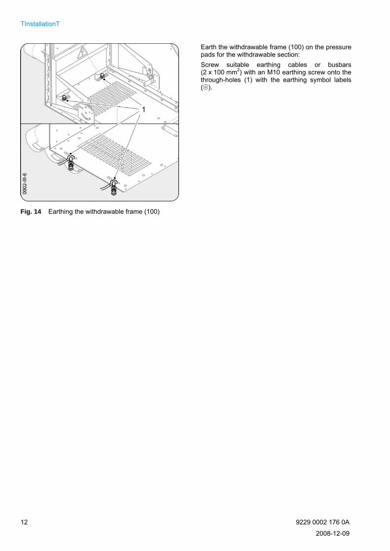
Earth the withdrawable frame (100) on the pressure pads for the withdrawable section: Screw suitable earthing cables or busbars (2 x 100 mm2) with an M10 earthing screw onto the through-holes (1) with the earthing symbol labels ( ).
Fig. 14 Earthing the withdrawable frame (100)
12 9229 0002 176 0A
2008-12-09

Operation
Operation
DANGER
High voltage! Mortal danger! • Do not touch live parts!
• Make sure that the withdrawable module with the SION® vac-uum circuit-breaker is operated only by qualified personnel who are familiar with the operating instructions and who com-ply with the warning notices.
WARNING
Risk of injury! During operation of electrical switching devices and systems, haz-ardous voltages are present in parts of the withdrawable module with the SION® vacuum circuit-breaker. Mechanical parts may move fast, also by remote control. • Do not remove covers!
• Do not reach into openings!
• Do not touch circuit-breaker poles!
Using the SION® vacuum circuit-breaker with a withdrawable section in the withdrawable frame
Insert the SION® vacuum circuit-breaker with with-drawable section in the fitted withdrawable frame (100) and push it in the direction indicated by the arrow.
Fig. 15 Inserting the SION® vacuum circuit-breaker in the withdrawable frame (100)
9229 0002 176 0A 13
2008-12-09

Operation
Slide the SION® vacuum circuit-breaker with with-drawable section into the withdrawable frame (100) up to the side stops (large arrow); to do this, move the locking handles towards the center of the cir-cuit-breaker (small arrows).
NoteIf an undervoltage release 3AX1103… is fitted, it must be connected to control voltage for switching operations (mechanical or electrical), as otherwise closing is not possible.
Fig. 16 Inserting and locking the SION® vacuum circuit-breaker with withdrawable section in the with-drawable frame (100)
CAUTION
®When moving it on the withdrawable section, make sure that the SION vacuum circuit-breaker is in the following state:
• OPEN (OFF) position
• Closing spring relaxed
Insert the handle of the withdrawable section 3AX1430-2C in the withdrawable section's coupling and turn it clockwise to move the SION® vacuum circuit-breaker up to a tangible stop.
Fig. 17 Moving the SION® vacuum circuit-breaker with withdrawable section in the withdrawable frame (100)
14 9229 0002 176 0A
2008-12-09

Installation accessories
Installation accessories
DANGER
High voltage! Mortal danger! • Do not touch live parts!
• Make sure that the SION® vacuum circuit-breaker in the with-drawable frame is operated only by qualified personnel who are familiar with the operating instructions and who comply with the warning notices.
WARNING
Risk of injury! • Do not touch live parts!
• Before and during installation in switchgear, check that mini-mum clearances from insulated and live parts, as well as parts subject to spring force, are maintained.
Assembling installation accessories
Fitting contact arms and systems
1. Grease the screwed-in parts of the threaded rods with Vaseline.
2. Screw in the threaded rod, paying attention to correct choice of the screw-in depths.
Fig. 18 Cleaning and fitting threaded rods for contact arms
9229 0002 176 0A 15
2008-12-09

Installation accessories
1. Firmly screw threaded rods onto contact faces.
Tightening torque for
M12: 40 ±4 Nm
M16: 100 ±10 Nm
Tightening torques apply to greased threads only.
2. Roughen the faces of the copper contact arms,
– clean them and
–
– grease them with Vaseline.
Clean faces with silver-plated contact faces
– and grease
– them with Vaseline.
Fig. 19 Cleaning and fitting contact arms (120)
Fig. 20 Fitting contact arms (120)
16 9229 0002 176 0A
2008-12-09

Installation accessories
For contact arms (120) (in the case of rated operat-ing current Ir ≤ 1250 A), insert them with Ø 40 mm contact arm adapters in the contact system (110): 1. Grease the contact finger in the contact sys-
tem (110) with Molykote Longterm 2
2. Adjust the contact arm adapter in the contact system (110) with the screw, washers and nut
3. Tighten the contact arm adapter with an open-ended wrench in the contact system (110)
4. Undo the screw with washers and nut.
Fig. 21 Preparing contact systems (120) (up to 24 kV, 1250 A)
Fit the contact system (110) onto the threaded rod and contact arm (120), paying attention to the posi-tion of the contact system (round outer edge to-wards the contact arm).
Firmly screw down the contact system (110) with a torque wrench. Tightening torque for M12: 40 ±4 Nm Tightening torques apply to greased threads only. Grease the other side of the contact system (110) with Molykote Longterm 2.
Fig. 22 Securing contact systems (110) on contact arms (120) with
Ø 40 mm
9229 0002 176 0A 17
2008-12-09

Installation accessories
On one side (round outer edge), grease the inside of the contact system (110, on the contact fingers) with Molykote Longterm 2. In the case of contact arms (120) with Ø 60 mm (rated operating current Ir > 1250 A), fit contact sys-tems (110) without a contact arm adapter onto the threaded rod and contact arms (pay attention to the contact system's position: round outer edge to-wards the contact arm).
Firmly screw down the contact system (110) with a torque wrench. Tightening torque for M16: 100 ±10 Nm Tightening torque applies to greased threads only! Grease the other side of the contact system (110) with Molykote Longterm 2.
Fig. 23 Securing contact systems (110) on contact arms (120) with
Ø 60 mm
Fitting the bushing and mating contact
Screw bushings (140) with mating contacts (141), each with • 4 saucer-head screws DIN 603 M8x25-8.8 with
a square neck
• contact washers and
• hexagon nuts
onto a non-ferromagnetic steel sheet in the func-tional unit or the rear of the withdrawable frame (100). Tightening torque: 25 ±2 Nm Tightening torque applies to greased threads only! Fit the bushing cover (142) from the other side.
Fig. 24 Securing the bushing (140) with mating contact (141) onto the withdrawable frame (100) or sheet
18 9229 0002 176 0A
2008-12-09

Installation accessories
Withdrawable frame with earthing switch
Fitting the withdrawable frame with earthing switch
Prepare fitting of the withdrawable frame with earthing switch as described in Section Preparations, page 9. To secure the withdrawable frame with earthing switch in the functional unit, Ø 6.6 mm holes can be produced in the functional unit's space in conformity with the hole pattern of the withdrawable frame's side walls, and steel L-brackets (see Fig. 25) can be placed under it. Insert the withdrawable frame with earthing switch and lower it onto the L-brackets.
Fig. 25 Fitting the withdrawable frame with earthing switch
NoteWhen securing the withdrawable frame with earthing switch in the functional unit, ensure that the earthing switch is installed so that easy access is possible if it later becomes necessary to replace the earthing switch gearing.
Fig. 26 Earthing switch gearing detail
9229 0002 176 0A 19
2008-12-09

Installation accessories
For connection of the main conductors, the busbars with the geometries and dimensions shown in Fig. 27 must be used in accor-dance with the switch version listed in
Fig. 28. The busbars must be dimensioned in compliance with DIN 43670 (aluminium busbars) or DIN 43671 (copper busbars).
Fig. 27 Busbars
a/f: width across flats, distance between top and bottom contact arms Ur: Rated voltage Ir: Rated operating current Isc: Rated short-circuit breaking current Fig. 28 Busbar dimensions
Dimensions Switch version Busbar version
A (mm) B (mm) C (mm) D (mm) E (mm) F (mm) G (mm) H (mm) J (mm) K (°) L (mm)
1) 87,5 237,5 146 59 32 30 16 30 20 115 - a/f: 275 mm U ≤ 17.5 kV; r
I ≤ 1250 A, r
I 31.5 kA sc
1) 87,5 257,5 146 59 32 30 16 30 20 115 - a/f: 310 mm U ≤ 17.5 kV; r
I ≤ 1250 A, r
I 31.5 kA sc
U 1) 37,5 267,5 174,1 59 32 35 23,5 35 20 135 - ≤ 17.5 kV; r
I > 1250 A, r
I 31.5 kA sc
U 1) 37,5 320,5 164 59 32 30 15 30 20 135 - 24 kV; r
I ≤ 1250 A, r
I 25 kA sc
U 1) 37,5 320,5 164 59 32 35 23 35 20 135 - r 24 kV; I > 1250 A, r
I 25 kA sc
U 2) 27,2 221,5 171 32 - 35 23,5 30 - 135 2x □12.5 r ≤ 17.5 kV; I 3150 A, r
I 40 kA sc
20 9229 0002 176 0A
2008-12-09

Installation accessories
NoteThe busbars of the earthing switch must be stabi-lized during their connection.
Fig. 29 Connecting busbars
Operation
To operate the earthing switch • Push the slider up (vertical arrow)
• Insert the earthing switch handle 3AX1430-2D (or 3AX1430-3D in the case of the 7.2 – 17.5 kV, 40 kA version) completely
Fig. 30 Preparing operation of the earthing switch with withdrawable module and SION
® vacuum circuit-
breaker
9229 0002 176 0A 21
2008-12-09

Installation accessories
To switch on Turn the earthing switch handle 3AX1430-2D (or 3AX1430-3D) clockwise through 180°. To switch off Turn the earthing switch handle 3AX1430-2D (or 3AX1430-3D) counterclockwise through 180°.
NoteDue to a built-in return lock, it is only possible to turn back the earthing switch handle when the end position has been reached and 180° rotation has been completed.
Fig. 31 Closing the earthing switch with withdrawable module and SION
® vacuum circuit-breaker
Remove the earthing switch handle when the earthing switch is activated. The opening for the earthing switch handle stays open, and the indicator of the earthing switch shows:
Fig. 32 Earthing switch with withdrawable module and SION
® vacuum circuit-breaker earthed
22 9229 0002 176 0A
2008-12-09

Installation accessories
Interlocks
Position of the vacuum circuit-breaker
Remo-ved
Insert/ Disconnected po-sition
Move Connected posi-tion remove*
Circuit-breaker pri-mary contacts closed X Circuit-breaker
cannot be moved Circuit-breaker
cannot be moved
Circuit-breaker pri-mary contacts open
Earthing switch closed X X X Circuit-breaker
cannot be moved
Earthing switch open
Possible
X Not possible * Inserting or removing the circuit-breaker into/from the withdrawable frame
Fig. 33 Interlocks
NoteEarthing switch handle 3AX1430-2D (or 3AX1430-3D) inserted or earthing switch activated • Moving the withdrawable unit not possible
• Handle for withdrawable section 3AX1430-2C cannot be inserted
• Withdrawable section cannot be removed from the withdrawable frame.
Handle for withdrawable section 3AX1430-2C inserted or withdrawable section between connected and discon-nected positions: • Activating the earthing switch not possible
• Opening for the earthing switch handle 3AX1430-2D (or 3AX1430-3D) cannot be operated.
9229 0002 176 0A 23
2008-12-09
Installation accessories Blank page
24 9229 0002 176 0A
2008-12-09

Maintenance
Maintenance
DANGER
Risk of injury! Working on the withdrawable module with the SION® vacuum cir-cuit-breaker activated/deactivated and with the spring energy store charged can lead to mortally serious injuries. • Disconnect the operating voltage and switch off the low-
voltage supply before performing maintenance work!
• Close and open the vacuum circuit-breaker manually. By doing so, you will make sure that the circuit-breaker is open and that the spring energy store is relaxed.
• Close and open the vacuum circuit-breaker manually. By doing so, you will make sure that the circuit-breaker is open and that the spring energy store is relaxed.
Maintenance
General The SION® vacuum circuit-breaker requires no maintenance under normal conditions. We nevertheless recom-mend a regular visual check. For optimum insulation, the insulating parts must be clean: • Switch off the low-voltage supply before performing maintenance work!
• In the event of heavy soiling, wipe off all other parts with a lint-free cleaning cloth.
• Grease the contact faces to busbars with Vaseline.
Accessories and spare parts – Manufacturer's product liability – Service
Accessories
Accessories Order number
Circuit-breaker hand crank 3AX1530-2B
Withdrawable section handle 3AX1430-2C
Earthing switch handle 3AX1430-2D or 3AX1430-3D (for 7.2 – 17.5 kV, 40 kA version)
Molykote Longterm 2 contact grea-se
3AX1133-2L
Operating instructions 9229 0002 176
Fig. 34 Accessories available for ordering
Replacing spare parts To ensure that the unit remains in reliable working order, spare parts may only be replaced by trained and certified personnel.
9229 0002 176 0A 25
2008-12-09

Maintenance
Product liability The manufacturer's product liability will be rendered null and void if at least one of the following criteria applies: • Original Siemens spare parts are not used.
• Fitters performing replacement have not been trained and certified by Siemens PTD M C.
• Parts have been incorrectly fitted or adjusted.
• Settings are not made in accordance with Siemens specifications.
• After installation and setting, no final check is performed with a tester approved by PTD M C including docu-mentation of the test results.
So that documentation can be kept complete, it is important for measurement results to be submitted to PTD M C Q.
Service For details of contacts for service work, consult Siemens PTD Services • Tel.: +49 180/5247000
• Fax: +49 180/5242471 or
• on the Internet at the Web address: www.siemens.com/energy-support
• by e-mail: [email protected]
• or any local Siemens office.
Disposal
If possible, the materials of the withdrawable module should be recycled. Disposal of the withdrawable module with minimum environmental impact is possible on the basis of existing legal regulations. The components of the withdrawable module, of the SION® vacuum circuit-breaker and of the installation accesso-ries can be recycled as mixed scrap, although dismantling to the maximum extent possible into sorted scrap and mixed scrap residues is more environmentally sustainable. Electronic scrap must be disposed of in accordance with applicable regulations. The ® withdrawable module with the SION vacuum circuit-breaker consists of the following materials: • Steel (partly phosphatized, galvanized and yellow chromated)
• Copper (partly silver-plated)
• Aluminum (partly silver-plated)
• Plastics (polyamide, polyester, polycarbonate, ABS-PC mixture; partly fiberglass-reinforced)
• Rubber materials
• Ceramics
• Lubricants
When delivered by Siemens, the circuit-breaker does not contain any hazardous substances in terms of the haz-ardous substances regulations applicable to the territory of the Federal Republic of Germany. For operation out-side the Federal Republic of Germany, the applicable local laws and regulations must be complied with. Packing materials, consisting of galvanized sheet steel, wood, cardboard, plastic foils (VCI foil, PE and PP) and hoops (PET), should also be recycled after correct sorting or should be passed on for disposal. Contact your Siemens service center if you require further information.
26 9229 0002 176 0A
2008-12-09

Index
Index
Locking ....................................................................15 A Locking handles ......................................................15 Accessories ............................................................ 27
Assembly ................................................................ 17 M Main conductor........................................................22 B Maintenance............................................................27 Busbar .................................................. 12, 13, 22, 23 Mass..........................................................................9 Busbar terminal......................................................... 8 Mating contact .................................................8, 9, 20 Busbar version........................................................ 22 Mixed scrap .............................................................28 Bushing..................................................... 8, 9, 12, 20 Molykote Longterm 2...................................19, 20, 27 Bushing cover ........................................... 8, 9, 12, 20 O C Operation.................................................................14 Circuit-breaker hand crank 3AX1530-2B................ 27
Classification to IEC 62271-100 ............................... 9 P Connected position................................................. 25 Packing..............................................................3, 4, 7 Contact arm ............................ 8, 9, 17, 18, 19, 20, 22 Pole center distance..................................................9 Contact arm adapter ............................................... 19 Pressure pad ...........................................................13 Contact face...................................................... 18, 27 Primary contacts......................................................25 Contact finger ......................................................... 19 Product liability ........................................................28 Contact system......................................... 8, 9, 19, 20
R Control voltage........................................................ 15 Rated frequency........................................................9 Crane transport..................................................... 3, 6 Rated lightning impulse withstand voltage................9
D Rated operating current ................................9, 19, 22 Data, technical .......................................................... 9 Rated short-circuit breaking current ....................9, 22 Disconnected position............................................. 25 Rated short-circuit duration .......................................9 Disposal .................................................................. 28 Rated short-time AC voltage .....................................9
Rated short-time current ...........................................9 E Rated voltage ......................................................9, 22 Earthing .................................................................. 13 Rating plate ...............................................................9 Earthing switch ............................. 7, 9, 21, 23, 24, 25 Return lock ..............................................................24 Earthing switch handle 3AX1430-2D or 3D............ 27
Earthing switch indicator......................................... 24 S E-mail...................................................................... 28 Scope of delivery.......................................................9
Service ....................................................................28 F Service work............................................................28 Fitting ...................................................................... 11 Shutter.......................................................................8 Functional unit ...................................... 10, 11, 20, 21 Shutter operating mechanism ...................................8
G Spare parts..............................................................27 Grease ...................................... 12, 17, 18, 19, 20, 27 Storage......................................................................7
Switch version .........................................................22 H Swivel lever ...............................................................8 Hand crank, circuit-breaker 3AX1530-2B................. 9 System-side isolation shells ......................................9 Handle, earthing switch 3AX1430-2D or 3D. 9, 23, 24
Handle, withdrawable section 3AX1430-2C ........... 15 T Handle, withdrawable section 3AX1430-2C (optional)
.............................................................................. 9 Technical data ...........................................................9 Threaded rod.........................................17, 18, 19, 20
Hole pattern ...................................................... 11, 21 Transport ...................................................................3 Humidity, relative ...................................................... 7 Transport beam...................................................3, 10
Type designation.......................................................9 I Type identification .....................................................9 Inserting .................................................................. 15
Installation............................................................... 10 U Installation accessories........................................... 17 Undervoltage release ..............................................15 Interlocks .......................................................... 10, 25 Unpacking .................................................................3 Internet.................................................................... 28
V L Vacuum circuit-breaker ...............................................
... 3, 4, 6, 7, 8, 9, 10, 14, 15, 17, 23, 24, 25, 27, 28 L-bracket........................................................... 11, 21 Link ........................................................................... 8 9229 0002 100 0A 27
2008-12-09

Index Vaseline ................................................12, 17, 18, 27 Withdrawable section ......................... 8, 9, 13, 14, 15 Versions .................................................................... 9 Withdrawable section handle 3AX1430-2C............ 27
Works serial number................................................. 9 W Workshop crane ....................................................... 6 Weight ....................................................................... 6 Width across flats.................................................... 22 Y Withdrawable frame..3, 6, 8, 9, 11, 13, 14, 15, 20, 25 Year of manufacture................................................. 9 Withdrawable module .................3, 6, 8, 9, 23, 24, 28
28 9229 0002 176 0A
2008-12-09

Blank page
9229 0002 176 0A 29
2008-12-09

Published by
Published by Energy Sector Power Distribution Division Medium Voltage Components Berlin Schaltwerk switchgear factory D - 13629 Berlin