Embed Size (px)
Citation preview

Operating Instructions for the Cutting Mill SM 100
© Retsch GmbH, 42781-Haan, Rheinische Str.36, Germany, Doc.No. E 98.734.0199/9999 A

19.08.1999 © Retsch GmbH 2 Doc.No. E 98.734.0199/9999 A
Guide to the Operating Instructions
The present operating instructions for the cutting mill of the type SM 100 gives all the information necessary for the areas indicated in the table of contents. They give instructions to the target group(s) defined for the respective areas on how to handle the SM 100 in a safe and proper fashion. Knowledge of the relevant chapters is, for the respective target group(s), a prerequisite for safe and proper handling. The present technical documentation is a work of reference and a training manual. Each of the individual chapters is an independent unit. These operating instructions do not include any repair instructions. In the case of any necessary repairs, please contact your supplier or Retsch GmbH directly.

19.08.1999 © Retsch GmbH 3 Doc.No. E 98.734.0199/9999 A
Guide to the Operating Instructions.................................................... 2 Safety................................................................................................. 4
Safety instructions ........................................................................................ 4 Warning signs .............................................................................................. 5 Repairs ....................................................................................................... 5 Confirmation............................................................................................... 5
Technical Data................................................................................... 6 Application in the case of normal use.............................................................. 6 Drive.......................................................................................................... 6 Speed ......................................................................................................... 6 Rated power ................................................................................................ 6 Input grain size ............................................................................................ 7 Volume of collecting vessel ........................................................................... 7 Noise data................................................................................................... 7 Type of protection / safety equipment ............................................................ 7 Dimensions of machines in mm ..................................................................... 7 Weight........................................................................................................ 7 Required standing area .................................................................................. 7
Transport and setting up .................................................................... 8 Packing....................................................................................................... 8 Transport.................................................................................................... 8
Temperature fluctuations .............................................................. 8 Intermediate storage ..................................................................... 8
Scope of supply ........................................................................................... 8 Parameters for setting-up location .................................................................. 9
Ambient temperature .................................................................... 9 Relative humidity .......................................................................... 9 Setting-up altitude......................................................................... 9
Setting up with underframe ........................................................................... 9 Setting up on a laboratory table ...................................................................... 9 Electrical connection .................................................................................... 10
Operation .......................................................................................... 11 Operating elements and operation .................................................................. 11
Graphic view of the operating elements: ............................................. 11 Operating elements and their function ............................................................ 12
Overview for Fig.4 .......................................................................... 12 Opening and closing of the mill housing.......................................................... 13
SM 100 comfort ............................................................................. 13 Insert bottom sieve ...................................................................................... 13 Filter hose and collecting vessel...................................................................... 14 Feed material to be ground ............................................................................ 14 Replacing knives .......................................................................................... 15 Replacing the Cutting Strips........................................................................... 15
Areas of application for the funnels ..................................................... 16 Preparations for the grinding operation ........................................................... 16 Standard funnel ........................................................................................... 16
Feed of material to be crushed when using the standard funnel ...... 16 Funnel for long material................................................................................ 17
Feed of material using the funnel for long material......................... 17 Bulk material funnel ..................................................................................... 18
Feed of the material to be crushed using the bulk material funnel... 18 General .............................................................................................. 19
Cleaning ............................................................................................... 19 Tests .......................................................................................................... 19
Cutting gap................................................................................... 19 Limit switch.................................................................................. 20
Maintenance................................................................................................ 20 Copyright.................................................................................................... 21 Changes...................................................................................................... 21 Accessories ................................................................................................. 21
Warranty Conditions .......................................................................... 22

Safety
Target group: All persons concerned in any way with the machine.
The SM 100 is a highly modern, efficient product from Retsch GmbH. It is state of the art. If the user handles the machine in accordance with the material and is familiar with the present technical documentation, it is completely safe operationally.
Safety instructions You, as the operator, must ensure that the persons instructed to work with the SM 100:
* have noted and understood all the regulations for the safety area,
* know all instructions for what action to take as well as the regulations of the relevant target groups before work is commenced,
* have access to the technical documentation at all times and without problem,
* that new personnel is familiarised before commencement of work on the SM 100 with the safe and proper handling either by a verbal introduction from a competent person and/or by means of the present technical documentation.
* Improper operation can result in personal injury and damage to property. You are responsible for your own safety and that of your personnel.
* Ensure that no unauthorised persons have access to the SM 100.
For your own protection, make sure that you are given confirmation that your personnel have received instruction in the use of the SM 100. You will find a draft of a related form after the chapter on safety.
!
We exclude any claims for compensation for material damage and personal injury caused by non-observance of the following safety instructions.
19.08.1999 © Retsch GmbH 4 Doc.No. E 98.734.0199/9999 A

Warning signs We give warnings using the following symbols:
!
Personal injury
Material damage
Repairs These operating instructions do not include any repair instructions. For your own safety, repairs may only be carried out by Retsch GmbH or an authorised agent (service technicians).
Should the need arise, please notify:
the Retsch agency in your country
your suppliers
Retsch GmbH directly
Your service address:
___________________________________________
___________________________________________
___________________________________________
___________________________________________
Confirmation I have noted the foreword and the chapter on safety.
_______________________________________ Operator's signature
_______________________________________ Service technician's signature
19.08.1999 © Retsch GmbH 5 Doc.No. E 98.734.0199/9999 A

Technical Data Machine type designation: SM 100 Application in the case of normal use
SM 100 standard For applications where numerous batches of the same input materials - in small or large quantities - are processed and the doors must be opened after each grinding cycle so that the grinding chamber can be cleaned.
SM 100 comfort For applications where different kinds of input materials have to be processed and the doors must be opened after each grinding cycle so that the grinding chamber can be cleaned.
The SM 100 is suitable for uses where the same grinding materials, also in large quantities, are to be crushed periodically and it is not absolutely necessary for the door to be opened after grinding to clean the grinding chamber, It is also used for crushing elastic, hard-ductile and fibrous products and product mixtures in batches or continuously. It is not designed as a production machine, but as a laboratory unit, meant for 8-hour single-shift operation. Furthermore, the SM 100 is basically not designed for grinding wet or moist materials. The special shape of the cutting tools combined with the drive gives fast, efficient grinding without interference from the material being crushed.
Do not make any modifications to the machine and use only RETSCH approved spares and accessories. Failure to comply will invalidate the CE declaration and guarantee.
Here are the special features * fast, gentle crushing with 3 blades distributed over the
circumference of the rotor and 4 cutting strips distributed within the housing
* multiple-use cutting tools of high-grade materials * consistent operational safety in all user-relevant unit components * versatile in use with unit variants and a wealth of accessories
Drive SM100 standard 1 and 3 phase AC motors. SM100 comfort 1 and 3 phase AC motors with brake.
Speed 1430min-1 at 50Hz 1690min-1 at 60Hz
Rated power 1500 Watt
19.08.1999 © Retsch GmbH 6 Doc.No. E 98.734.0199/9999 A

19.08.1999 © Retsch GmbH 7 Doc.No. E 98.734.0199/9999 A
Input grain size max. 20mm
Volume of collecting vessel * up to 5,000 ml max. with standard collecting vessel as a function of
the material being crushed and extendable to • 30,000ml max. with components available as accessories
Noise data Noise measurement according to DIN 45635-31-01-KL3 Noise data are dependent on the fracturing properties fo the product beeing ground. Example: Sound power level: LWA = 84 dB(A) Workplace-related emission LpAeq = 81 dB(A) Operating conditions: Bottom sieve : 0,5mm Conidur Sample material: food pellets, grain size up to 15 mm Filling ratio of grinding chamber: feeding quantity each until motor rated power is reached.
Type of protection / safety equipment IP 54 Feed funnel according to EN 294 Discharge nozzle according to EN 294
Dimensions of machines in mm SM 100 standard With standard hopper Height approx.945 Width approx.420 Depth approx.445 With base and standard hopper Height approx.1560 Width approx.560 Depth approx.700
SM 100 comfort With standard hopper Height approx.945 Width approx.420 Depth approx.520 With base and standard hopper Height approx.1560 Width approx.560 Depth approx.700
Weight SM 100 standard Without base or hopper net approx. 43kg With base and standard hopper net approx. 64kg SM 100 comfort Without base or hopper net approx. 47kg With base and standard hopper net approx. 68kg
Required standing area 700 mm x 560 mm; no safety distances necessary!

Transport and setting up Target group: Operators, Forwarders, Users
Packing The packing is adjusted to the transport route. It complies with the generally applicable packing regulations.
Please keep the packing for the whole of the guarantee period. If, in the case of a complaint, the unit is returned in inadequate packing, your guarantee rights may be jeopardised.
Transport
The SM 100 may not be subjected to shocks, shaken or thrown during transport. Otherwise the electrical and mechanical components may be damaged.
Temperature fluctuations
In the case of major temperature fluctuations (e.g. with transportation by air), the SM 100 must be protected against condensation. Otherwise the electrical components may be damaged.
Intermediate storage Ensure that the SM 100 is also kept dry when subject to intermediate storage. Scope of supply
* SM 100 * Filter hose and adapter * 5l collecting vessel * Operating instructions
Check that the consignment is complete, including the individually ordered accessories.
Check that the SM 100 is in perfect working condition (see chapter on Operation).
If the consignment is incomplete and/or damaged during transport, you must notify the forwarder and Retsch GmbH without delay (within 24 h). Later complaints may not be considered.
19.08.1999 © Retsch GmbH 8 Doc.No. E 98.734.0199/9999 A

Parameters for setting-up location
Ambient temperature The ambient temperature should be between 5°C and 40°C.
When the ambient temperature exceeds or falls below that specified, the electronic and mechanical components may be damaged, and performance data changed to an unknown extent.
Relative humidity Maximum relative humidity 80 % at temperatures of 31°C, falling in a linear fashion to 50 % relative humidity at 40°C.
At higher humidity, the electronic and mechanical components may be damaged, and performance data changed to an unknown extent.
Setting-up altitude max. 2000 m above sea level
Setting up with underframe
8
9
1
2
3
4
5
6
7
Fig.1
Fig.2
We recommend that the SM 100 be mounted on an underframe which can be obtained as an accessory. Fig.1 Assembly: * Connect middle cross-piece 9 and base side parts 8 using
the cylinder-head screws 1 * Push cover caps 2 on the projecting thread * Place stand tube 3 in the sleeve 4 and screw tightly with
the headless screws 5 * If necessary, the underframe can be aligned with the
cylinder-head screws 6
To be able to fasten the underframe to the floor with screws, maximum size of 10 mm diam. possible, the two setting screws 6 and the front plastic caps 7 must be removed.
* Place the SM 100 on the underframe Fig.2 * To fasten the hexagon-head screws SCH M8x35 supplied
with the underframe, use spring washers and hexagonal nuts.
The SM 100 is supplied without feed funnels. These must be ordered separately as accessories and mounted by the customer, The available funnels, see the chapter "Areas of application for the funnels", are fastened with the fasteners of the plate "X", after the plate "X" has been removed. Do not forget the Vulkollan seal.
!
Never operate the SM 100 without the cover plate “X“ or a feed funnel. Danger of injury to the skin and hands.
Setting up on a laboratory table
19.08.1999 © Retsch GmbH 9 Doc.No. E 98.734.0199/9999 A

Fig.3
You can also set the SM 100 up on your laboratory table. Fig.3 * Measure laboratory table thickness A * Use screws SCH with a maximum diam. of 8mm and a
length of the laboratory table thickness A + 25mm * Mark holes for the table with reference to the holes
present on the motor of the SM 100
The distance between the holes and the front edge of the table B must be such that it is easily possible to mount and dismount the collective vessel or the filter hose.
Electrical connection The electrical connection may only be made by an electrician.
* The voltage and frequency of the SM 100 can be found on the nameplate.
* Ensure that the values agree with the applicable power supply.
* Connect the SM 100 to the power supply using the
connection cable supplied. The power cable supplied does not have a plug because the type of plug depends on the setting-up location and the relevant regulations in the country concerned
* When connecting the power cable to the power supply, provide an external fuse in accordance with the regulations of the setting-up location.
If the values on the nameplate are not observed, electronic and mechanical components may be damaged.
Before operating for the first time, the direction of rotation must be checked, see rotation arrow on the. If the direction of rotation is incorrect the grinding will be inadequate and mechanical parts may be damaged.
19.08.1999 © Retsch GmbH 10 Doc.No. E 98.734.0199/9999 A

Operation
Target group: Users
Operating elements and operation Graphic view of the operating elements:
0 I
0 I
Fig.4
The standard feed funnel shown above is an accessory, see also the chapter "Areas of application for the funnels".
19.08.1999 © Retsch GmbH 11 Doc.No. E 98.734.0199/9999 A

Operating elements and their function Overview for Fig.4
Item Element Figure Function A Power switch with
ON/OFF button 0 I
Isolates and connects the SM 100 from/with the power supply I depressed = SM 100 is switched on 0 depressed = SM 100 is switched off
A1 Power switch with knob
Isolates and connects the SM 100 from/with the power supply ON = SM 100 is switched on OFF = SM 100 is switched off
B Door lock cylinder-head screw
.
Opens and closes the door of the SM 100, clamps the door seal Clockwise = locks the door Anticlockwise = opens the door Tool needed = key C
B1 Door lock Handwheel only with SM 100 comfort
Opens and closes the doors of the SM 100 comfort, tensions the door seal. Press down and turn clockwise to lock the doors. Press down and turn anti-clockwise to open the doors.
C Key for door lock B
Is needed to open and close the door lock with the cylinder-head screw on the SM 100
D Filter hose o. Fig. Prevents back-up of the compressed air generated by the rotating beater cross and thus speeds up material.
E Collecting vessel 5l o. Fig. Collects the crushed material. F Adjustment screws
on underframe
Makes it possible to align the underframe if there is an uneven floor. When screwed out they expose openings with which it is possible to fasten the underframe with the floor, diam. 10mm
G Feed slide
When drawn, opens up the material feed. Pushes material to be ground onto the rotor.
H Feed flap
Opens and closes the feed shaft. Makes it possible to feed the material to be crushed. Prevents anyone from reaching into the grinding chamber.
I Metering slide
Pushes material to be ground into the feed shaft area * Pulled out: Feed flap H can be opened, material to be ground can be fed in. * Pushed in: Feed flap H cannot be opened, material to be ground remains in the area of the feed slide G.
J Locking bolt
Blocks or releases the feed slide G. * Pulled out: Free movement of the feed slide G possible. * Released: Feed slide G locks in top position.
K Bottom sieve no Fig. Influences with the size and type of perforation the end fineness of the material.
L Motor brake release lever, only with SM 100 comfort
Press back to release the motor brake so that the beater rotor can be removed for cleaning.
X Cover plate no Fig. Prevents anyone reaching into the grinding chamber when no feed funnel has been mounted. (As-delivered condition)
19.08.1999 © Retsch GmbH 12 Doc.No. E 98.734.0199/9999 A

Opening and closing of the mill housing
0 I
Fig.5.1
Fig.5.2
Fig.6
SM 100 standard Only open when the SM 100 is switched off, even if a limit switch on the left hand side of the mill housing switches the SM 100 off when the door is opened.
* Press button 0 on main switch A Fig.5.1 or turn to OFF position. Fig.6
* Place key C in screw B
* When the key is turned to the left, this opens the housing
• Close in reverse direction
SM 100 comfort Only to be opened when the SM 100 is switched off. • Press button 0 on main switch A or turn to OFF position.
Fig.6 • Press handwheel B1 and turn anti-clockwise. Fig.5.2 • Handwheel latches into end position.
Follow the above procedure in reverse to close.
Only close the door when the contact surfaces are absolutely free of ground material or other contaminants. Mechanical components and the seal may be damaged.
!
Do not open the SM 100 when the motor is running. When crushing toxic or otherwise health-hazardous materials there is a danger that health-endangering particles will be inhaled.
!
Do not open the SM 100 and the motor brake simultaneously. Danger of injury from unbraked cross beater.
Insert bottom sieve
Fig.7
For the purpose of coarse precrushing it is also possible to work without bottom sieve K. Bottom sieves of stainless steel with Conidur or square perforations are also available as accessories. Fig.7
Conidur 0.25/0.50/0.75/1.0/1.5/2.0mm
Square hole 4.0/6.0/8.0/10.0mm
* Stop the SM 100
* Open mill housing
* Insert bottom sieve K
* Close mill housing Make sure that a collecting vessel is mounted.
* Start the SM 100
19.08.1999 © Retsch GmbH 13 Doc.No. E 98.734.0199/9999 A
Filter hose and collecting vessel
Fig.8
With the use of a cloth filter hose between the SM 100 and the collecting vessel, the air flow caused by the rotor is taken off and a backlog of material is prevented. Furthermore this accelerates the material throughput and ensures a gentle crushing process.
* Push the filter hose D over the flange, holding the clip at an angle
* Clamp lock D1
* Suspend collecting vessel E
* Clamp locks E1
Feed material to be ground See also the chapter "Areas of application for the funnels". The SM 100 can be retrofitted with a 30l plastic vessel, available as an accessory, for batch or continuous operation. * Feed material slowly into the feed funnel
Only feed material into the SM 100 when it is running. Blockages can damage mechanical components.
Feed material slowly and continuously into the feed funnel. Excessive feed quantities may force the SM 100 to stop and this may damage mechanical components.
!
During grinding, dust may escape from the feed funnel. Use an extraction device in the case of toxic or otherwise health-hazardous grinding materials. Danger of inhaling health-endangering dust.
!
Many materials form explosive air mixtures. Check the properties of the material you are crushing. Explosion hazard!
19.08.1999 © Retsch GmbH 14 Doc.No. E 98.734.0199/9999 A
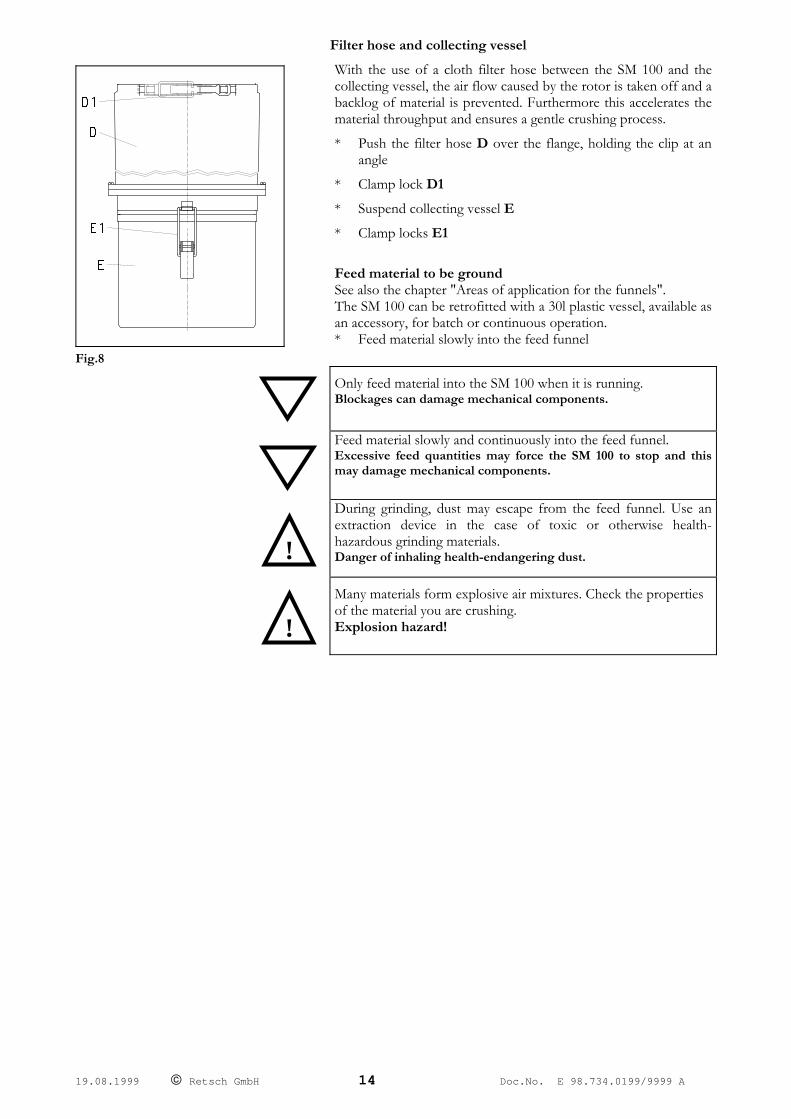
Replacing knives
Fig.9
Fig.10
• Pull out the mains power supply plug. • Open door T. Fig.9
• Remove screws S2 (AF6) and spring washer F1.
• Remove rotor.
• Clean the housing of the mill.
• Remove screws S1 (AF5).
• Replace knife M. Fig.10
• Tighten screws S1 (applied torque = 12N/m)
• Grease motor shaft.
• Slip the rotor on to the motor shaft.
• Tighten screw S2 and spring washer F1 (applied torque = 14N/m).
• Set the gap between the knife and cutting strips as described in "Replacing the Cutting Strips". Gap setpoint value >0.2mm <0.3mm.
Replacing the Cutting Strips
61
29
73
Fig.11
Fig.12
• Pull out the mains power supply plug.
• Open the doors.
• Clean the housing of the mill.
• Remove cheesehead screws 73. Fig.11
• Replace cutting strips 29.
• Make the cheesehead screws 73 finger tight.
• Check the gap between knife M and cutting strips 29 with a feeler gauge. Fig.12 (setpoint value = >0.2mm <0.3mm).
• To close the gap: Loosen screw 73, insert setscrews 61, turn clockwise, make screw 73 finger tight.
• Check constantly with a feeler gauge.
• After setting tighten cheesehead screw 73.
• Applied torque = 7 N/m.
• To open the gap: Loosen screw 73, remove setscrews 61, turn anti-clockwise, make screw 73 finger tight.
• Check constantly with a feeler gauge.
• After setting tighten cheesehead screw 73.
• Applied torque = 7 N/m.
19.08.1999 © Retsch GmbH 15 Doc.No. E 98.734.0199/9999 A

Areas of application for the funnels ( It is not claimed that this list is exhaustive! )
Target group: Laboratory personnel
Preparations for the grinding operation
* insert the bottom sieve of your choice * close the door * fasten a collecting vessel to the discharge * switch the SM 100 on
Only feed material into the SM 100 when it is running. Blockages can cause mechanical damage.
Standard funnel
Fig.9 In most cases this universal-use funnel can be used. It is suitable, e. g., for: * rubber and special waste * shaped plastic parts * leather scraps For further information, just contact our application laboratory.
If moist material is to be ground, the wooden slide is to be pulled out of the funnel to the top position after grinding to enable it to dry. The pusher will swell when wet and will jam.
Fig.9
Feed of material to be crushed when using the standard funnel Fig.9 * switch the SM 100 on * pull the feed slide G and the metering slide I * open the feed flap H and feed the material to be crushed * close the feed flap H and if necessary push the material with
the metering slide I * grasp the handle of the feed slide G * pull the locking bolt J and push the feed slide G slowly
downwards
19.08.1999 © Retsch GmbH 16 Doc.No. E 98.734.0199/9999 A
Do not use excessive force in pushing the feed slides. Blockages can cause mechanical damage.
In most cases the dead weight of the feed slide is sufficient to push the material into the grinding chamber. Should this not be the case, the material may be pushed gently and, within the SM 100's capacity, with the feed slide.
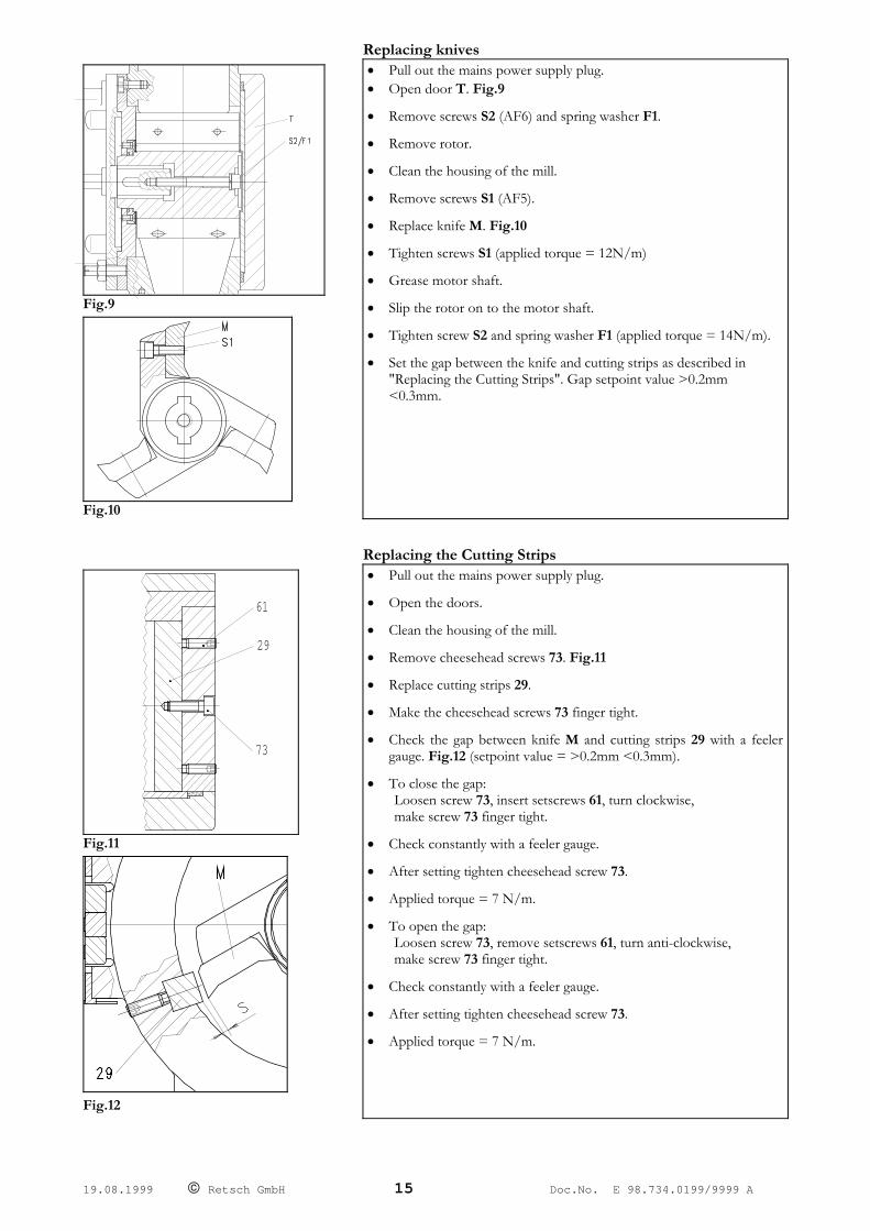
SM Fig.10
Funnel for long material Fig.10 This funnel is suitable for feeding mainly long materials. For example: * cable scraps * carpet waste * straw, grass and similar material * branches, twigs and similar material The opening of the feed apron inside the funnel is 30x130mm. For further information, just contact our application laboratory.
Feed of material using the funnel for long material
Fig.10 * switch the SM 100 on * place material in the funnel * push material in by hand * push the material over the guard wedge in the funnel using
the wooden slide
!
When dealing with long material, make sure to wear protective gloves. The material is drawn in by the SM 100. Otherwise injuries are possible to the skin and hands.
When pushing the material beyond the guard wedge in the funnel, only use the wooden slide supplied with the unit. When using other aids, mechanical components may be damaged.
!
Do not feed in any lumpy material. Danger of injury from material being hurled back.
19.08.1999 © Retsch GmbH 17 Doc.No. E 98.734.0199/9999 A

Bulk material funnel
Fig.11
Fig.11 This funnel is used when feeding mainly bulk materials, e.g.: * all pourable bulk materials * animal feed pellets The maximum opening of the baffle, rebound guard, inside the funnel is 20x84mm. For further information, just contact our application laboratory.
Feed of the material to be crushed using the bulk material
funnel Fig.11 * switch the SM 100 on * slowly feed the material into the funnel or allow it to pour
in,
The rebound guards located in the funnel prevent the material from being hurled out.
Feed the material in slow and careful doses, because the rotor may jam if overloaded. Mechanical parts can be damaged.
19.08.1999 © Retsch GmbH 18 Doc.No. E 98.734.0199/9999 A
General
Cleaning
Fig.16
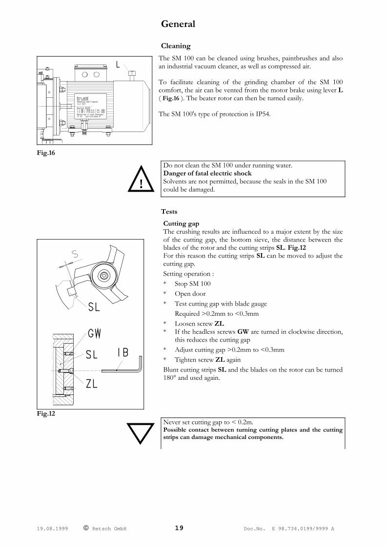
The SM 100 can be cleaned using brushes, paintbrushes and also an industrial vacuum cleaner, as well as compressed air.
To facilitate cleaning of the grinding chamber of the SM 100 comfort, the air can be vented from the motor brake using lever L ( Fig.16 ). The beater rotor can then be turned easily.
The SM 100's type of protection is IP54.
!
Do not clean the SM 100 under running water. Danger of fatal electric shock Solvents are not permitted, because the seals in the SM 100 could be damaged.
Tests
Fig.12
Cutting gap The crushing results are influenced to a major extent by the size of the cutting gap, the bottom sieve, the distance between the blades of the rotor and the cutting strips SL. Fig.12 For this reason the cutting strips SL can be moved to adjust the cutting gap. Setting operation : * Stop SM 100 * Open door * Test cutting gap with blade gauge Required >0.2mm to <0.3mm * Loosen screw ZL * If the headless screws GW are turned in clockwise direction,
this reduces the cutting gap * Adjust cutting gap >0.2mm to <0.3mm * Tighten screw ZL again Blunt cutting strips SL and the blades on the rotor can be turned 180° and used again.
Never set cutting gap to < 0.2m. Possible contact between turning cutting plates and the cutting strips can damage mechanical components.
19.08.1999 © Retsch GmbH 19 Doc.No. E 98.734.0199/9999 A

Limit switch
Every six months the limit switch on the left hand side of the SM 100 must be checked with regard to its serviceability. * Start the SM 100 * Open door * With an opening gap of 3mm max., the limit switch must shut down the motor.
Maintenance If moist or wet materials are ground, the SM 100 must be thoroughly cleaned and dried, because residual material must always be expected in the grinding chamber. Furthermore, with the above use the rotor must be regularly pulled off and the motor shaft lubricated.
Check the motor shaft and rotor regularly for corrosion spots. Otherwise it will no longer be possible to dismantle the rotor without considerable effort.
When grinding mainly moist material, a plastic slide is available as an accessory, provided the standard funnel is used. This prevents clogging due to swelling.
Changing the rotor
Fig.13
Pull the rotors as shown in Fig. 13.
• Stop the SM 100.
• Open the door.
• Unscrew the machine screw 84
• Turn down the machine screw 104
The rotor is slowly pulled forward when this is done.
• Clean and lubricate the motor shaft and the rotor.
• Plunger the rotor onto the motor shaft.
• Reinstall the machine screw 84 together with the lock washer.
The SM 100 is otherwise largely maintenance-free.
But we recommend that the following checks be conducted at the latest after every month, depending on user frequency:
• Check of cutting tools • Check of the rotor with regard to easy running, if necessary
clean and grease.
19.08.1999 © Retsch GmbH 20 Doc.No. E 98.734.0199/9999 A

19.08.1999 © Retsch GmbH 21 Doc.No. E 98.734.0199/9999 A
Copyright This documentation may only be passed on or duplicated and its content used or passed on with the express permission of Retsch GmbH. Any violation will be liable for compensation.
Changes We reserve the right to make technical changes.
Accessories (It is not claimed that this list is exhaustive! )
* various bottom sieves * standard funnel with wooden slide * plastic slide for standard funnel * funnel for long material * funnel for bulk material * 30 litre collective vessel of plastic * filter hose for 30 litre collecting vessel * filter unit for 5 litre collecting vessel * dirt collection tray
19.08.1999 © Retsch GmbH 22 Doc.No. E 98.734.0199/9999 A
Warranty Conditions
1. If legitimate claims are made we shall remedy the defect or replace the goods free of charge.
The purchaser shall only have a right to rescind the contract or reduce the purchase price if we have decided that it is not possible to remedy the defect and a replacement delivery cannot be made or the time limit therefore cannot be complied with or if a reasonable additional time limit of six weeks granted by the customer has not been complied with due to our fault.
If the remedy or replacement delivery in fact fails the customer shall have the right to reduce the price or rescind the contract at his discretion. Further claims, in particular for damages in relation to damage not caused to the goods themselves, such as lost production, are excluded in so far as we have not acted wilfully or negligently. For goods produced by third parties we pass on the liability of the manufacturer.
2. We shall bear the costs directly incurred through the remedying of defects or the replacement delivery on the condition that claim is found to be legitimite. This also applies to the freight costs as well as the reasonable costs of removal and installation. The customer, however, undertakes to bear the reasonable costs of providing his own technicians and assistants on site.
If our customer carries on business overseas, however, we shall be entitled to pay the costs, in particular costs of transport, tolls, wages and materials, ex German border.
3. The warranty term for newly manufactured goods is two years, for used it is one year.
The guarantee refers to deployment in a laboratory in 1-shift operation. In case of multi-shift operation or other areas of application, the guarantee term is shortened accordingly.
No warranty is given for parts subject to wear and tear.
4. We warrant that our goods are free from manufacturing defects. The suitability, classification and function of our goods are determined exclusively on the basis of the performance descriptions contained in the order confimation even if these differ from the order. In the latter event the customer may, within two weeks after receipt of the order confirmation, draw any possible difference from the order to our attention and come to an agreement on these with us. If the customer does not object to the specifications in the order confirmation then these shall be deemed to have been accepted.
Unless an agreement to the contrary has been reached, we shall not be held liable for the suitability of the goods delivered for the use to which the customer intends to put them. The same applies to performance figures expected by the customer unless we have been able to carry out appropriate preliminary practical experiments and have, in our order confirmation, declared in writing that these performance figures shall be binding.
5. Our warranty shall also become invalid if persons other than those employed by us carry out repairs or in any other way interfere with or make alterations to the goods delivered by us or do not use suitable parts to the extent that the defect is causally connected thereto. In addition , it is a condition of our warranty that our directions for use and operation be followed.
6. If, without a release having first been obtained from us, the goods are installed in and /or connected to, attached to or incorporated in other systems or production plants then our guarantee is limited exclusively to the parts delivered by us.
7. The remedying of defects or replacement of defective parts shall, at our discretion, be carried out on site or at the seat of our company. If the repair is carried out on site, the customer shall ensure that our employee has access, unlimited in either time or space, to the purchased item. In addition, the customer may only demand that work necessary in order to fulfil warranty obligations be carried out during the normal local business hours. If such work is carried out outside our normal business hours on request, the customer shall bear the additional costs. If he wishes to have other particular work performed which goes beyond the work warranted then these costs shall be payable at the actual valid price.