Embed Size (px)
Citation preview
- 1 -
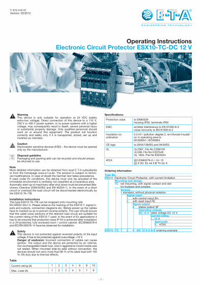
Operating InstructionsElectronic Circuit Protector ESX10-TC-DC 12 V
Y 310 410 01Version: 03/2012
Current rating (A) 1 2 3 4 6 8 10
Max. Load (A) 1 2 3 4 5 7 9
WarningThis device is only suitable for operation at 24 VDC (safety extra-low voltage). Direct connection of this device to a 110 V, 230 V or 400 V power system, or to power systems with a higher voltage, may consequently result in death, severe personal injury or substantial property damage. Only qualified personnel should work on or around this equipment. The product will function correctly and safely only if it is transported, stored, set up and installed as intended.
CautionElectrostatic sensitive devices (ESD) – the device must be opened only by the manufacturer.
Disposal guidelinePackaging and packing aids can be recycled and should always be returned to use.
NoteMore detailed information can be obtained from local E-T-A subsidiaries or from the homepage www.e-t-a.de. The product is subject to techni-cal modifications. In case of doubt the German text takes precedence.If used under Ex conditions, this device must only be actuated of the immediate environment is verifiably not classified as a hazardous area.Automatic start-up of machinery after shut down must be prevented (Ma-chinery Directive 2006/42/EG and EN 60204-1). In the event of a short circuit or overload the load circuit will be disconnected electronically by the ESX10-TA-/TB.
Installation instructionsThe type ESX10-TA-/TB can be snapped onto mounting rails EN 50022-35x7.5. Please observe the marking of the ESX10-T. signal in-puts and outputs, connection diagrams etc. Before power up the cables have to marked so as to prevent reverse polarity. The user should ensure that the cable cross sections of the relevant load circuit are suitable for the current rating of the ESX10-T used. In the event of Ex applications it has to be ensured that protection class IP 54 is achieved after installation in a UV-protected, fully enclosed room / control cabinet. IEC/EN60079-0 and IEC/EN 60079-14 have be observed for installation.
SafetyThis device is not protected against reversed polarity of the input voltage. It has to be protected against overvoltage >18 V. Danger of explosion: Incorrect connection of cables can cause ignition. The output and the device are protected by an internal, non-exchangeable blade fuse. Use in aggressive mixed media was not tested. When mounted side-by-side without convection, the devices should not carry more than 80 % of its rated load with 100 % ON duty due to thermal effects.
Table
Specifications:
Protection class to EN60529housing IP30, terminals IP00
EMC emitted interference to EN 61000-6-3noise immunity to EN 61000-6-2
Insulation co-ordination
0.5 kV / pollution degree 2, re-inforced insulati-on in operating area to IEC60934 / IEC60664
CE logo to 2004/108/EG and 94/9/EG
UL UL2367, File No E306740UL508, File No E322549UL 1604, File No E320024
ATEX IEC/EN60079-0 /-14/-15 II 3G Ex nA II B T4 Gc X
Ordering information
Type No.ESX10 Electronic Circuit Protector, with current limitation Mounting and design TC rail mounting, with signal contact and slot for busbars and jumpers Version 1 standard, without physical isolation Signal input 1 with control input IN+ 2 with reset input RE Signal output 4 status output SF Operating voltage DC 12 V rated voltage DC 12 V Current rating 1...10 A Approvals E ATEX
ESX10 -TC 1 2 4 -DC 12 V-6 A-E ordering example
- 2 -
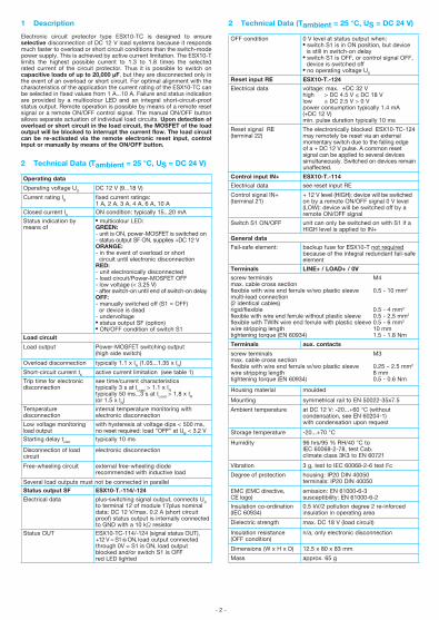
1 Description
Electronic circuit protector type ESX10-TC is designed to ensure selective disconnection of DC 12 V load systems because it responds much faster to overload or short circuit conditions than the switch-mode power supply. This is achieved by active current limitation. The ESX10-T limits the highest possible current to 1.3 to 1.8 times the selected rated current of the circuit protector. Thus it is possible to switch on capacitive loads of up to 20,000 µF, but they are disconnected only in the event of an overload or short circuit. For optimal alignment with the characteristics of the application the current rating of the ESX10-TC can be selected in fixed values from 1 A...10 A. Failure and status indication are provided by a multicolour LED and an integral short-circuit-proof status output. Remote operation is possible by means of a remote reset signal or a remote ON/OFF control signal. The manual ON/OFF button allows separate actuation of individual load circuits. Upon detection of overload or short circuit in the load circuit, the MOSFET of the load output will be blocked to interrupt the current flow. The load circuit can be re-activated via the remote electronic reset input, control input or manually by means of the ON/OFF button.
2 Technical Data (Tambient = 25 °C, US = DC 24 V)
Operating data
Operating voltage US DC 12 V (9...18 V)
Current rating IN fixed current ratings: 1 A, 2 A, 3 A, 4 A, 6 A, 10 A
Closed current I0 ON condition: typically 15...20 mA
Status indication by means of
l multicolour LED: GREEN: - unit is ON, power-MOSFET is switched on- status output SF ON, supplies +DC 12 V ORANGE: - in the event of overload or short circuit until electronic disconnection RED: - unit electronically disconnected - load circuit/Power-MOSFET OFF- low voltage (< 3.25 V)- after switch-on until end of switch-on delay OFF: - manually switched off (S1 = OFF) or device is dead- undervoltage l status output SF (option) l ON/OFF condition of switch S1
Load circuit
Load output Power-MOSFET switching output(high side switch)
Overload disconnection typically 1.1 x IN (1.05...1.35 x IN)
Short-circuit current IK active current limitation (see table 1)
Trip time for electronic disconnection
see time/current characteristicstypically 3 s at ILoad > 1.1 x IN typically 50 ms...3 s at ILoad > 1,8 x IN (or 1.5 x IN)
Temperaturedisconnection
internal temperature monitoring with electronic disconnection
Low voltage monitoring load output
with hysteresis at voltage dips < 500 ms, no reset required: load “OFF” at UB < 3.2 V
Starting delay tstart typically 10 ms
Disconnection of load circuit
electronic disconnection
Free-wheeling circuit external free-wheeling diode recommended with inductive load
Several load outputs must not be connected in parallelStatus output SF ESX10-T.-114/-124
Electrical data plus-switching signal output, connects US to terminal 12 of module 17plus nominal data: DC 12 V/max. 0.2 A (short circuit proof) status output is internally connected to GND with a 10 kΩ resistor
Status OUT ESX10-TC-114/-124 (signal status OUT),+12 V = S1 is ON, load output connected through 0V = S1 is ON, load output blocked and/or switch S1 is OFFred LED lighted
OFF condition 0 V level at status output when:lswitch S1 is in ON position, but device is still in switch-on delaylswitch S1 is OFF, or control signal OFF, device is switched off l no operating voltage US
Reset input RE ESX10-T.-124
Electrical data voltage: max. +DC 32 V high > DC 4.5 V ≤ DC 18 Vlow ≤ DC 2.5 V > 0 Vpower consumption typically 1.4 mA (+DC 12 V) min. pulse duration typically 10 ms
Reset signal RE(terminal 22)
The electronically blocked ESX10-TC-124 may remotely be reset via an external momentary switch due to the falling edge of a + DC 12 V pulse. A common reset signal can be applied to several devices simultaneously. Switched on devices remain unaffected.
Control input IN+ ESX10-T.-114
Electrical data see reset input RE
Control signal IN+(terminal 21)
+ 12 V level (HIGH): device will be switched on by a remote ON/OFF signal 0 V level (LOW): device will be switched off by a remote ON/OFF signal
Switch S1 ON/OFF unit can only be switched on with S1 if a HIGH level is applied to IN+
General data
Fail-safe element: backup fuse for ESX10-T not required because of the integral redundant fail-safe element
Terminals LINE+ / LOAD+ / 0V
screw terminals M4max. cable cross sectionflexible with wire end ferrule w/wo plastic sleeve 0.5 - 10 mm2
multi-lead connection (2 identical cables)rigid/flexible 0.5 - 4 mm2
flexible with wire end ferrule without plastic sleeve 0.5 - 2,5 mm2
flexible with TWIN wire end ferrule with plastic sleeve 0.5 - 6 mm2
wire stripping length 10 mmtightening torque (EN 60934) 1.5 - 1.8 Nm
Terminals aux. contacts
screw terminals M3max. cable cross sectionflexible with wire end ferrule w/wo plastic sleeve 0.25 – 2.5 mm2
wire stripping length 8 mmtightening torque (EN 60934) 0.5 - 0.6 Nm
Housing material moulded
Mounting symmetrical rail to EN 50022-35x7.5
Ambient temperature at DC 12 V: -20...+60 °C (without condensation, see EN 60204-1) with condensation upon request
Storage temperature -20...+70 °C
Humidity 96 hrs/95 % RH/40 °C to IEC 60068-2-78, test Cab.climate class 3K3 to EN 60721
Vibration 3 g, test to IEC 60068-2-6 test Fc
Degree of protection housing: IP20 DIN 40050 terminals: IP20 DIN 40050
EMC (EMC directive, CE logo)
emission: EN 61000-6-3susceptibility: EN 61000-6-2
Insulation co-ordination (IEC 60934)
0.5 kV/2 pollution degree 2 re-inforced insulation in operating area
Dielectric strength max. DC 18 V (load circuit)
Insulation resistance (OFF condition)
n/a, only electronic disconnection
Dimensions (W x H x D) 12.5 x 80 x 83 mm
Mass approx. 65 g
2 Technical Data (Tambient = 25 °C, US = DC 24 V)
- 3 -
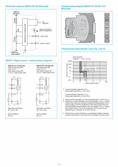
Schematic diagram ESX10-TB-124 (Example)
Time/Current characteristic curve (TA = 25 °C)
disconnection typically 1.1 x IN
IK
10000
1000
1 2 4
trip
tim
e in
sec
ond
s
...times rated current
100
10
1
0.1
0.013 50
1.8 x IN
5
current limitationtypically 1.8 x IN
*1) current limitation typically 1.8 x IN times rated current at IN = 0.5 A...6 A
current limitation typically 1.5 x IN times rated current at IN = 8 A or 10 A
l The trip time is typically 3 s in the range between 1.1 and 1.8 x IN*1).
l Electronic current limitation occurs at typically 1.8 x IN*1) which
means that under all overload conditions (independent of the power supply and the resistance of the load circuit) the max. overload before disconnection will not exceed 1.8 x IN
*1) times the current rating. Trip time is between 100 ms and 3 sec (depending on overload or at short circuit). l Without this current limitation a considerably higher overload current would flow in the event of an overload or short circuit.
ESX10-T Signal inputs / outputs (wiring diagram)
LINE+ 1
SF 23
IN 21
2 LOAD+
0V 3
Operating condition: SF +12 V = OK
fault condition: SF 0 V
Operating condition: SF +12 V = OK
fault condition: SF 0 V
LINE+ 1
SF 23
RE 22
2 LOAD+
0V 3
ESX10-TC-124-DC12Vwith reset input RE(+DC 12 V ↓)with status output SF(+12 V = load output ON)
ESX10-TC-114-DC12Vwith control input IN+(+DC 12 V )with status output SF(+12 V = load output ON)
ok
ono
reset
2 LOAD+
DC12VxxA
Ele
ktro
nisc
her
Sic
heru
ngsa
utom
atE
lect
roni
c C
ircui
t P
rote
ctor
ES
X10
-TC
-124
-DC
12V
-xxA
ww
w.e
-t-a
.com
xxxx
Ger
man
y
LINE+ 1
SF 23
RE 22
2 LOAD+
0V 3
Terminal wiring diagram ESX10-TC-124-DC 12 V (Example)
Fails
afe
Rse
nse
LINE (+)DC 24 V
LOAD (+)load output
0 V
SF status output
RE reset input
status indicationgreen/orange/red
S1ON/OFF
ele
ctr
on
ic c
on
tro
l u
nit
- 4 -
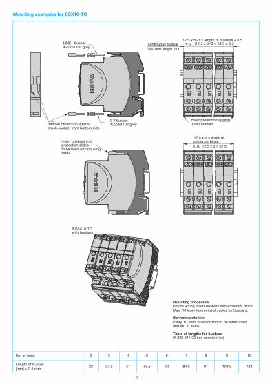
Mounting examples for ESX10-TC
LINE+ busbarX22261102 grey
(12.5 x n)-3 = length of busbars ± 0.5e. g. (12.5 x 5)-3 = 59.5 ± 0.5 continuous busbar
500 mm length, cut
0 V busbarX22261102 greyremove protection against
brush contact from bottom side
insert protection againstbrush contact
12.5 x n = width of protector blocke. g. 12.5 x 5 = 62.5
insert busbars and protection slidesto be flush with housing sides
5 ESX10-TCwith busbars
Mounting procedure:Before wiring insert busbars into protector block.Max. 10 insertion/removal cycles for busbars.
Recommendation:Every 10 units busbars should be interrupted and fed in anew.
Table of lengths for busbars (X 222 611 02 see accessories)
No. of units 2 3 4 5 6 7 8 9 10
Length of busbar[mm] ± 0.5 mm
22 34.5 47 59.5 72 84.5 97 109.5 122
- 5 -
4 Accessories
4.1 Description
The ESX10-T features an integral power distribution system. The following wiring modes are possible with various pluggable current busbars:
l LINE +DC 12 Vl 0 V Caution: The electronic devices ESX10-T require a 0 V connection
4.2 Accessories
Use original E-T-A accessories only!
l Busbars for LINE+ and 0 V max. load with one line entry (recommended: centre line entry) max. load with two line entries grey insulation, length: 500 mm X 222 611 02
l Busbars for LINE+ and 0 V grey insulation max. number of plug-on operations 10:
X 222 611 34 (3-unit-block ESX10-T), length: 34.5 mm
X 222 611 47 (4-unit-block ESX10-T), length: 47 mm
X 222 611 59 (5-unit-block ESX10-T), length: 59.5 mm X 222 611 97 (8-unit-block ESX10-T), length: 97 mm
X 222 611 12 (10-unit-block ESX10-T), length: 122 mm
l Connector bus link –K10 suitable for auxiliary contacts (series connection) X 210 589 02 (1.5 mm2, brown)
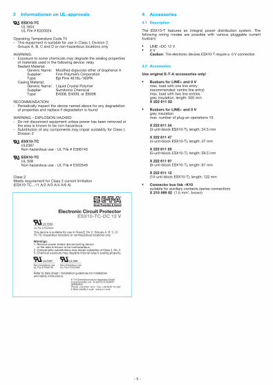
3 Informationen on UL-approvals
ESX10-TCUL1604UL File # E320024
Operating Temperature Code T5- This equipment is suitable for use in Class Ι, Division 2, Groups A, B, C and D or non-hazardous locations only
WARNING:- Exposure to some chemicals may degrade the sealing properties of materials used in the following device: relay Sealant Material: Generic Name: Modified diglycidyl ether of bisphenol A Supplier: Fine Polymers Corporation Type: Epi Fine 4616L-160PK Casing Material: Generic Name: Liquid Crystal Polymer Supplier: Sumitomo Chemical Type: E4008, E4009, or E6008 RECOMMENDATION:- Periodically inspect the device named above for any degradation of properties and replace if degradation is found
WARNING – EXPLOSION HAZARD:- Do not disconnect equipment unless power has been removed or the area is known to be non-hazardous- Substitution of any components may impair suitability for Class Ι, Division 2
ESX10-TCUL2367Non-hazardous use - UL File # E306740
ESX10-TC UL 508Non-hazardous use - UL File # E322549
Class 2Meets requirement for Class 2 current limitation(ESX10-TC...-/1 A/2 A/3 A/4 A/6 A)
This device is suitable for use in Class I, Div 2, Groups A, B, C, D; TC T5; Hazardous locations or nonhazardous locations only
Warnings:1. Remove power before disconnecting device or the area is known to be nonhazardous.2. Components substitutions may impair suitability of Class I , Div 2.3. Chemical exposure may degrade internal relay's sealing property.
Electronic Circuit Protector ESX10-TC-DC 12 V
UL1604
Non-hazardous useUL File # E306740
Refer to data sheet / installation guidelines for installation and safety instructions.
UL2367
UL File # E320024
UL508Non-hazardous useUL File # E322549
E-T-A Elektrotechnische Apparate GmbHIndustriestraße 2-8 · D-90518 ALTDORFGERMANYPhone: +49 9187 10-0 · Fax: +49 9187 10-397E-Mail: [email protected] · www.e-t-a.de
- 6 -
- 7 -
- 8 -
Notice
E-T-A Elektrotechnische Apparate GmbHIndustriestraße 2-8 · 90518 ALTDORFGERMANYPhone: +49 9187 10-0 · Fax +49 9187 10-397E-Mail: [email protected] · www.e-t-a.de
All dimensions without tolerances are for reference only. In the interest of improved design, performance and cost effectiveness the right to make changes in these specifications without notice is reserved. Product markings may not be exactly as the ordering codes. Errors and omissions excepted.