Embed Size (px)
Citation preview

www.e-t-a.de
Electronic Circuit Protector ESX10-T.-DC 24 V
1716 1
4
Description
Technical data (Tambient = 25 °C, operating voltage US = DC 24 V)
ESX10-TD
The model ESX10-T extends our product group of electronic over-current protection devices for DC 24 V applications. At a width of only 12.5 mm it provides selective protection for all DC 24 V load circuits. This is achieved by a combination of active electronic current limitation in the event of a short circuit and overload disconnection typically from 1.1 times rated current. The ESX10-T is track-mountable and provides ease of installation for groups of devices with several circuits.DC 24 V switch-mode power supplies are widely used in automation technology today. In the event of an overload, however, they turn down the output voltage which is intended to power all connected loads. So if there is a failure in a single load of the system, the supply voltage will break down also in all other load circuits. Not only does this frequently cause undefined fault conditions, but it can even lead to machine stop-pages or system downtimes.This is exactly where the ESX10-T comes in by responding to the overload conditions faster than the switch-mode power supply. The max. possible overcurrent is limited to typically 1.3 ... 1.8 times rated current (see table 1). This allows switching on capacitive loads of up to 75,000 µF, but a dis-connection will only be effected in the event of an overload or short circuit. For adjustment to the load conditions the current rating can be selected in fixed values from 0.5 A ... 12 A or in adjustable ratings, e.g. 2 A/4 A/6 A. Status and failure indication is by means of a multi-coloured LED, an inte-gral short circuit proof status output or by single or group alarms. Remote actuation is possible by a remote reset signal or a remote control signal ON/OFF. The manual ON/OFF switch on the device itself allows start-up of certain individual load circuits. As soon as the ESX10-T detects overload or short circuit in its load circuit, it blocks the load output transistor and disconnects the current flow in the faulty circuit. After remedy of the failure, the load output of the ESX10-T is re-activated by an electronic reset signal or manually by actuating the ON/OFF button. US patent number: US 6,490,141 B2US patent number: US 8,237,311 B2
Features
l Selective load protection, electronic trip characteristics. l Suitable for all kinds of loads (DC 24 V motors upon request)l Active current limitation for safe connection of capacitive loads
up to 75,000 µF and on overload/short circuit.l ESX10-TA/-TB: Current ratings 0.5 A...12 A ESX10-TD: adjustable ratings [0.5 A/1 A/2 A], [2 A/3 A/4 A], [2 A/4 A/6 A]
and [6 A/8 A/10 A]l Reliable overload disconnection with 1.1 x IN plus, even with long
load lines or small cable cross sections (see table 3).l Manual ON/OFF button (S1). l Control input IN+ for remote ON/OFF signal (option).l Electronic reset input RE (option).l Clear status and failure indication through LED, status output SF
or Si contact F.l Integral fail-safe element adjusted to current rating.l Width per unit only 12.5 mm.l Symmetrical rail mountingl Ease of wiring through busbar LINE+ and 0 V as well as signal bars
and bridges. l Other versions available with ATEX approval
Marking: II 3G Ex nA IIB T4 Gc X ESX10-TA-...-E and ESX10-TB-...E
Please observe the separate user manual:
Operating data Operating voltage US DC 24 V (18...32 V)
Current rating IN fixed current ratings: Type ESX10-TA-... and -TB-...: 0.5, 1 A, 2 A, 3 A, 4 A, 6 A, 8 A, 10 A, 12 A adjustable ratings: Type ESX10-TD-...: [0.5 A/1 A/2 A], [2 A/4 A/6 A], [6 A/8 A/10 A] Type ESX10-TD-101-...: [2 A/3 A/4 A]
Closed current I0 ON condition: typically 20...30 mA depending on signal output
Status indication l multicolour LED:by means of Green: - unit is ON, power-MOSFET is switched on - status output SF ON, supplies + DC 24 V Orange: - in the event of overload or short circuit until electronic disconnection Red: - unit electronically disconnected - load circuit/Power-MOSFET OFF OFF: - manually switched off (S1 = OFF) or device is dead - undervoltage (US < 8 V) - after switch-on till the end of the delay period
l status output SF (option) l potential-free signal contact F (option) l ON/OFF/ condition of switch S1
Load circuitLoad output Power-MOSFET switching output (high side switch)
Overload disconnection typically 1.1 x IN (1.05...1.35 x IN)
Short-circuit current IK Active current limitation with ILimit = typically 1.8/1.5/1.4/4.3 x IN, ILimit depending on IN (typical ILimit - values see table 1)
Trip characteristic active current limitation (see table 1)
Trip thresholds/trip times 1. threshold: (t1, t2) at overcurrent at Iload> typically 1.1 x IN...ILimit: (ILimit see table 1) t1 = typically 3s. 2. threshold: at Iload = ILimit: t2 = typically 100 ms...3 s.
Temperature disconnection internal temperature monitoring with electronic disconnection
Low voltage monitoringload output with hysteresis, no reset required load “OFF” at US < 8 V http://www.e-t-a.de/qr1006/

Electronic Circuit Protector ESX10-T.-DC 24 V
www.e-t-a.de
Electronic Circuit Protector ESX10-T.-DC 24 V
1716 2
4
Starting delay tstart typically 0.5 sec after every switch-on and after applying US
Disconnection of load circuit electronic disconnection
Free-wheeling circuit external free-wheeling diode recommended with inductive load
Several load outputs must not be connected in parallel
Status output SF ESX10-T.-114/-124/-127Electrical data plus-switching signal output, connects US to terminal 12 of module 17plus nominal data: DC 24 V / max. 0.2 A (short circuit proof) status output is internally connected to GND with a 10 kOhm resistor
Status OUT ESX10-TB-114/-124 (signal status OUT), at US = +24 V +24 V = S1 is ON, load output connected through 0V = S1 is ON, load output blocked and/or switch S1 is OFF red LED lighted Status OUT ESX10-TB-127 (signal status OUT
inverted), at UB = + 24 V + 24 V = S1 is ON, load output locked red LED lighted 0 V = S1 is ON, load output connected and/or switch S1 is OFF
OFF condition 0 V level at status output when: l switch S1 is in ON position, but device is still in switch-on delay l switch S1 is OFF, or control signal OFF, device is switched off l no operating voltage US
Signal output F ESX10-T.-101/-102Electrical data potential-free signal contact max. DC 30 V/0.5 A, min. 10 V/10 mA
ON condition LED green voltage US applied, switch S1 is in ON position no overload, no short circuit
OFF condition LED off l device switched off (switch S1 is in OFF position) l no voltage US applied
Fault condition LED orange overload condition > 1.1 x IN up to electronic disconnection
Fault condition LED red electronic disconnection upon overload or short circuit
ESX10-TB-101 single signal, make contact contact SC/SO-SI open
ESX10-TB-102 single signal, break contact contact SC/SO-SI closed
Fault signal output fault conditions: l no operating voltage US l ON/OFF switch S1 is in OFF position l red LED lighted (electronic disconnection)
Reset input RE ESX10-T.-124/-127Electrical data voltage: max. + DC 32 V high > DC 8 V ≤ DC 32 V low ≤ DC 3 V > 0 V power consumption typically 2.6 mA (+DC 24 V) min. pulse duration typically 10 ms
Reset signal RE The electronically blocked (terminal 22) ESX10-TB-124/-127 may remotely be reset via an external momentary switch due to the falling edge of a +24 V pulse. A common reset signal can be applied to several devices simultaneously. Switched on devices remain unaffected.
Technical data (Tambient = 25°C, operating voltage US = DC 24 V) Technical data (Tambient = 25°C, operating voltage US = DC 24 V)
Control input IN+ ESX10-T.-114Electrical data see reset input REControl signal IN+ +24V level (HIGH): device will be switched (terminal 21) on by a remote ON/OFF signal 0 V level (LOW): device will be switched off by a remote ON/OFF signal
Switch S1 ON/OFF unit can only be switched on with S1 if a HIGH level is applied to IN+
LED display ON: LED green OFF: LED red
General dataFail-safe element: backup fuse for ESX10-T not required because of the integral redundant fail-safe element
Terminals LINE+ / LOAD+ / 0Vscrew terminals M4max. cable cross section rigid and flexible 0.5 – 16 mm2
flexible with wire end ferrule w/wo plastic sleeve 0.5 – 10 mm2
wire stripping length 10 mmtightening torque (EN 60934) 1.5 – 1.8 Nmmulti-lead connection (2 identical cables)rigid/flexible 0.5 – 4 mm2
flexible with wire end ferrule without plastic sleeve 0.5 – 2,5 mm2
flexible with TWIN wire end ferrule with plastic sleeve 0.5 – 6 mm2
Terminals aux. contactsscrew terminals M3max. cable cross sectionflexible with wire end ferrule w/wo plastic sleeve 0.25 – 2.5 mm2
wire stripping length 8 mmtightening torque (EN 60934) 0.5 – 0.6 Nm
Housing material moulded
Mounting symmetrical rail to EN 60715-35x7.5
Ambient temperature -25...+60 °C 1) (without condensation, see EN 60204-1) 1) Ambient temperature range can differ
depending on approvals
Storage temperature -40...+70 °C
Humidity 96 hrs/95 % RH/40 °C to IEC 60068-2-78, test Cab. climate class 3K3 to EN 60721
Vibration 3 g, test to IEC 60068-2-6 test Fc
Degree of protection housing: IP20 EN 60529 terminals: IP20 EN 60529
EMC emission: EN 61000-6-3(EMC directive, CE logo) susceptibility: EN 61000-6-2
Insulation co-ordination 0.5 kV/2 pollution degree 2(IEC 60934) re-inforced insulation in operating area
dielectric strength max. DC 32 V (load circuit)
Insulation resistance (OFF condition) n/a, only electronic disconnection
Approvals CE Marking to 2014/30/EU(ESX10-TA/-TB/-TD) UL 2367, File # E306740, Solid State Overcurrent Protectors UL 508, File # E322549 „Industrial
Control Equipment“ GL, Certificate # 4676212 HH
(ESX10-TA/-TB) UL 1604, File # E320024 (class Ι, division 2, groups A, B, C, D) CSA C22.2 No: 14, File # 016186 CSA C22.2 No: 142, File # 016186 CSA C22.2 No: 213 (class Ι, division 2) ATEX 2014/34/EU II 3G Ex nA IIB T4 Gc XDimensions (W x H x D) 12.5 x 80 x 83 mm
Mass approx. 65 g

www.e-t-a.de
Electronic Circuit Protector ESX10-T.-DC 24 V
1716 3
4
Electronic Circuit Protector ESX10-T.-DC 24 V
Ordering information Ordering number code ATEX versions: ...-E
Type No.ESX10 Electronic Circuit Protector, with current limitation Mounting and design TA rail mounting, without signal contact TB rail mounting, with signal contact and slot for busbars and jumpers TD rail mounting, with signal contact and switch for 3-step current rating adjustment Version 1 standard, without physical isolation in the event of a failure Signal input 0 without signal input 1 with control input IN+, only ESX10-T-114 2 with reset input RE, only ESX10-T-124, ESX10-T-127 Signal outputs 0 without signal output (only ESX10-TA) 1 signal contact N/O 2 signal contact N/C 4 status output SF (only ESX10-T-114, ESX10-T-124) 7 inverse status output SF (only ESX10-T-127 Operating voltage DC 24 V rated voltage DC 24 V Current rating 0.5 A 1 A 2 A 3 A 4 A 6 A 8 A 10 A 12 A 16 A (only ESX10-TB-101) 0.5/1/2 A adjustable (only ESX10-TD-...-X278) 2/4/6 A adjustable (only ESX10-TD-...-X279) 6/8/10 A adjustable (only ESX10-TD-...-X280) 2/3/4 A adjustable (only ESX10-TD-101-...-X282)
ESX10 - TA 1 0 0 - DC 24 V -6 A ordering example
l The user should ensure that the cable cross sections of the relevant load circuit are suitable for the current rating of the ESX10-T used.
l Automatic start-up of machinery after shut down must be prevented (Machinery Directive 2006/42/EG and EN 60204-1). In the event of a short circuit or overload the load circuit will be disconnected electronically by the ESX10-T.
Attention!Please observe separate data sheet for ESX10-TB-101-DC 24 V-16 A.
Description of ESX10-T signal inputs and outputs see wiring diagrams.
Table 1: voltage drop, current limitation, max. load current
Notes
current rating IN
typically
voltage drop UON at IN
active current limitation ILimit (typically)
max. load current at 100% ON duty, UB DC24V
Ta = 40 ° C Ta = 50 ° C Ta = 60 ° C
0.5 A 70 mV 1.8 x IN 0.5 A 0.5 A 0.5 A
1 A 80 mV 1.8 x IN 1 A 1 A 1 A
2 A 130 mV 1.8 x IN 2 A 2 A 2 A
3 A 80 mV 1.8 x IN 3 A 3 A 3 A
4 A 100 mV 1.8 x IN 4 A 4 A 4 A
6 A 130 mV 1.8 x IN 6 A 6 A 6 A
8 A 120 mV 1.5 x IN 8 A 8 A 8 A
10 A 150 mV 1.5 x IN 10 A 10 A 9.8 A
12 A 180 mV 1.3 x IN 12 A 11 A 9.8 A
[0.5/1/2 A] 70/80/ 130 mV
1.4 x IN 0.5/1/2 A 0.5/1/2 A 0,5/1/2 A
[2/3/4 A] 130/80/ 100 mV
1.4 x IN 2/3/4 A 2/3/4 A 2/3/4 A
[2/4/6 A] 130/100/ 130 mV
1.4 x IN 2/4/6 A 2/4/6 A 2/4/6 A
[6/8/10 A] 130/120/ 150 mV
1.4 x IN 6/8/10 A 6/8/10 A 6/8/9.8 A
Attention: when mounted side-by-side without convection the ESX10-T should not carry more than 80 % of its rated load with 100 % ON duty due to thermal effects.
Preferred types Standard current ratings (A)
ESX10-TA/TB 0.5 1 2 3 4 6 8 10 12 0.5 / 1 / 2 2 / 4 / 6 6 / 8 / 10
ESX10-TA-100-DC24V- x x x x x x x x x
ESX10-TB-101-DC24V- x x x x x x x x x
ESX10-TD 0.5 1 2 3 4 6 8 10 12 0.5 / 1 / 2 2 / 4 / 6 6 / 8 / 10
ESX10-TD-101-DC24V- x x x
Preferred types
Type No.ESX10 Electronic Circuit Protector, with current limitation Mounting and design TA rail mounting, without signal contact TB rail mounting, with signal contact and slot for busbars and jumpers Version 1 standard, without physical isolation Signal input 0 without signal input 1 with control input IN+ (only ESX10-T.-114) 2 with reset input RE (only ESX10-T.-124, ESX10-T.-127) Signal outputs 0 without signal output (only ESX10-TA) 1 signal contact N/O 2 signal contact N/C 4 status output SF (only ESX10-T.-114, ESX10-T.-124) 7 inverse status output SF (only ESX10-T.-127) Operating voltage DC 24 V rated voltage DC 24 V Current rating 0.5...12 A Approvals E ATEX
ESX10 - TB-1 0 1- DC 24 V- 6 A -E Ordering information

Electronic Circuit Protector ESX10-T.-DC 24 V / Installation guidelines and safety instructions
www.e-t-a.de
Electronic Circuit Protector ESX10-T.-DC 24 V
1716 4
4
Terminal wiring diagram ESX10-TB-124 (Example)
ESX10-TB-124-…
Fails
afe
Rse
nse
LINE (+)DC 24 V
LOAD (+)load output
0 V
SF status output
RE reset input
status indicationgreen/orange/red
S1ON/OFF
ele
ctr
on
ic c
on
tro
l u
nit
Schematic diagram ESX10-TB-124 (Example)
LINE+ 1
SF 23
RE 22
2 LOAD+
0V 3
Ele
ctro
nic
Circ
uit
Pro
tect
orE
SX
10-T
B-1
24-D
C24
V-x
xA
xxxx
2223
TB-124
22 23
ok
reset
onoff
xxA
2 LOAD+
GE
RM
AN
Y
Approvals
ESX10-TA/-TB and -TD
Authority Standard Voltage rating Current ratings
UL UL 2367 DC 24 V 0.5 A…16 A
UL UL 1604 (Class I, Division 2, Groups A, B, C, D) DC 24 V 0.5 A…12 A
UL UL 508 C22.2 No 14
DC 24 V 0.5 A…16 A
GL Rules VI, part 7, GL 2012, category C, EMC1
DC 24 V 0.5 A...12 A
ESX10-TA and -TB
Authority Standard Voltage rating Current ratings
CSA C22.2 No 14 C22.2 No 142M C22.2 No 213-M (Class I, Division 2)
DC 24 V 0.5...12 A
TÜV ATEX 2014/34/EU Annex VIII EN 60079-0 EN 60079-11 EN 60079-15
DC 24 V
Table 2: ESX10-T - product version
Version Signal input Signal output
Signal output F (Signal contact) Status output SF
ESX10-.. without Control inputON/OFF +24 V
Control IN+
Reset input+24 V RE
without single signalN/O
(normally open NO)
single signalN/C
(normally closed NC)
without Status OUT+24 V = OK
Status OUT0 V = OK
-TA -100 x x x
-TB/-TD -101 x x x
-TB/-TD -102 x x x
-TB/-TD -114 x x
-TB/-TD -124 x x x
-TB/-TD -127 x x x
www.e-t-a.de
Electronic Circuit Protector ESX10-T.-DC 24 V / Installation guidelines and safety instructions
1716 5
4
Electronic Circuit Protector ESX10-T.-DC 24 V
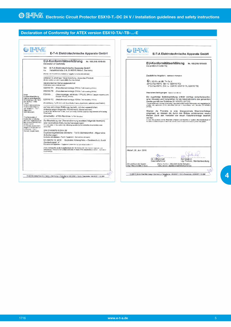
Declaration of Conformity for ATEX version ESX10-TA/-TB-...-E

Electronic Circuit Protector ESX10-T.-DC 24 V / Installation guidelines and safety instructions
www.e-t-a.de
Electronic Circuit Protector ESX10-T.-DC 24 V
1716 6
4
Information on UL approvals/CSA approvalsDimensions ESX10-TA
83
3.27
803.15
3.15
Phoenix label ZBF 12
snap-on socket forsymmetrical rail EN 50022-35x7.5
12.5.492
80
ok
ono�
reset
2 LOAD+
GE
RM
AN
Y
Dimensions ESX10-TB
12.5
80
80
83
snap-on socket forsymmetrical rail EN 50022-35x7.5Phoenix label ZBF 12
3.27 .492
3.15
3.15
GE
RM
AN
Y
Dimensions ESX10-TD
833.27
12.5.492
80
803.15
3.15
switch for currentrating adjustment
snap-on socket forsymmetrical rail EN 50022-35x7.5Phoenix label ZBF 12
ok
ono�
reset
2 LOAD+
x Ax A
xx A
GE
RM
AN
Y
ESX10-TA/-TB/-TD UL2367 Non-hazardous use - UL File # E306740
UL 508 Non-hazardous use UL File # E322549
E322549 INDUSTRIAL CONTROL EQUIPMENT
ESX10-TA / -TB UL1604
UL File # E320024
Operating Temperature Code T4- This equipment is suitable for use in ClassⅠ, Division 2, Groups A, B, C and D or non-hazardous locations only.
T4 A / 0 °C to 50 °C
WARNING:- Exposure to some chemicals may degrade the sealing properties of materials used in the following device: relay (K1) • Sealant Material: Generic Name: Modified diglycidyl ether of bisphenol A Supplier: Fine Polymers Corporation Type: Epi Fine 4616L-160PK • Casing Material: Generic Name: Liquid Crystal Polymer Supplier: Sumitomo Chemical Type: E4008, E4009, or E6008 RECOMMENDATION:- Periodically inspect the device named above for any degradation of properties and replace if degradation is found
WARNING – EXPLOSION HAZARD:AVERTISSEMENT – RISQUE D’EXPLOSION • Do not disconnect equipment unless power has been removed
or the area is known to be non-hazardous. Avant de deconnecter l’equipment, couper le courant ou s’assurer que l’emplacement est designe non dangereux.
• Substitution of any components may impair suitability for Class I, Division 2. La substitution de composants peut rendre ce materiel inacceptable pour les emplacements de class I, division 2.
This device is OPEN type equipment that must be used within a suita-ble end-use system enclosure, the interior of which is accessible only through the use of a tool. The suitability of the enclosure is subject to investigation by the local Authority Having Jurisdiction at the time of installation.
Wiring to or from this device, which enters or leaves the system enclosure, must utilize wiring methods suitable for Class I, Division 2 Hazardous Locations, as appropriate for the installation.
ESX10-TA / -TB CSA C22.2 No: 14 - File # 016186 CSA C22.2 No: 142 - File # 016186 CSA C22.2 No: 213 (ClassⅠ, Division 2) - File # 016186
Class 2Meets requirement for Class 2 current limitation(ESX10-T...-0.5 A / 1 A / 2 A / 3 A)

www.e-t-a.de
Electronic Circuit Protector ESX10-T.-DC 24 V / Installation guidelines and safety instructions
1716 7
4
Electronic Circuit Protector ESX10-T.-DC 24 V
ESX10-T Signal inputs / outputs (wiring diagram)
LINE+ 1
LOAD+2
0V 3
ESX10-TA-100without signal input/output
LINE+ 1
SF 23
IN 21
2 LOAD+
0V 3
ESX10-TB-114with control input IN+(+DC 24 V)with status output SF(+24 V = load output ON)
operating condition: SF +24 V = OKfault condition: SF 0 V
LINE+ 1
SF 23
RE 22
2 LOAD+
0V 3
ESX10-TB-124with reset input RE(+DC 24 V ↓)with status output SF(+24 V = load output ON)
operating condition: SF +24 V = OKfault condition: SF 0 V
LINE+ 1
14
13
2 LOAD+
0V 3
ESX10-TB-101without signal inputwith signal output F(single signal, N/O)
operating condition: 13-14 closedfault condition: 13-14 open
LINE+ 1
12
11
2 LOAD+
0V 3
ESX10-TB-102without signal inputwith signal output F(single signal, N/C)
operating condition: 11-12 openfault condition: 11-12 closed
LINE+ 1
SF 23
RE 22
2 LOAD+
0V 3
ESX10-TB-127with reset input RE(+DC 24 V ↓)with inverse status output SF(0 V = load output ON)
operating condition: SF 0 V = OKfault condition: SF +24 V
ESX10-TDSchematic diagram similar to ESX10-TB, without signal busbars (on top)
ESX10-T signal inputs / outputs (schematic diagrams)Auxiliary contacts are shown in OFF or error condition

Electronic Circuit Protector ESX10-T.-DC 24 V / Installation guidelines and safety instructions
www.e-t-a.de
Electronic Circuit Protector ESX10-T.-DC 24 V / Installation guidelines and safety instructions
17168
4
disconnection typically 1.1 x IN
current limitationtypically 1.8 x IN
IK
10000
1000
1 2 4
trip
tim
e in
sec
ond
s
...times rated current
100
10
1
0.1
0.01
3 50
1.8 x IN
5
Time/Current characteristic curve (TA = 25 °C)
Table 3: Reliable trip of ESX10-T
l The trip time is typically 3 s in the range between 1.1 and 1.8 x IN (e.g. ESX10-TB-...-6 A) l Electronic current limitation ILimit occurs at typically 1.8 x IN
which means that under all overload conditions (independent of the power supply and the resistance of the load circuit) the max. overload before disconnection will not exceed 1.8 x IN times the current rating. The individual current limitation value ILimit depends on the current rating (see table1). Trip time is between 100 ms and 3 sec (depending on overload or at short circuit).
l Without this current limitation a considerably higher overload
current would flow in the event of an overload or short circuit.
Reliable trip of ESX10 with different cable lengths and cross sections
Resistivity of copper ρ0 = 0.0178 (Ohm x mm2) / m
US = DC 19.2 V (= 80 % of 24 V) voltage drop of ESX10-T and tolerance of trip point (typically 1.1 x IN = 1.05 ... 1.35 x IN) have been taken into account.
ESX10-T-selected rating IN (in A) ➞
e. g. trip current Iab = 1.25 x IN (in A)) ➞
Rmax in Ohm = (US / Iab) - 0.050 ➞
3 6
3.75 7.5 ➞ESX10-T trips after 3 s
5.07 2.51
The ESX10-T reliably trips from 0 Ohm to max. circuitry resistance Rmax
Cable cross section A in mm2 ➞ 0.14 0.25 0.34 0.5 0.75 1 1.5
cable length L in meter (= single length) cable resistance in Ohm = (R0 x 2 x L) / A
5 1.27 0.71 0.52 0.36 0.24 0.18 0.12
10 2.54 1.42 1.05 0.71 0.47 0.36 0.24
15 3.81 2.14 1.57 1.07 0.71 0.53 0.36
20 5.09 2.85 2.09 1.42 0.95 0.71 0.47
25 6.36 3.56 2.62 1.78 1.19 0.89 0.59
30 7.63 4.27 3.14 2.14 1.42 1.07 0.71
35 8.90 4.98 3.66 2.49 1.66 1.25 0.83
40 10.17 5.70 4.19 2.85 1.90 1.42 0.95
45 11.44 6.41 4.71 3.20 2.14 1.60 1.07
50 12.71 7.12 5.24 3.56 2.37 1.78 1.19
75 19.07 10.68 7.85 5.34 3.56 2.67 1.78
100 25.34 14.24 10.47 7.12 4.75 3.56 2.37
125 31.79 17.80 13.09 8.90 5.93 4.45 2.97
150 38.14 21.36 15.71 10.68 7.12 5.34 3.56
175 44.50 24.92 18.32 12.46 8.31 6.23 4.15
200 50.86 28.48 20.94 14.24 9.49 7.12 4.75
225 57.21 32.04 23.56 16.02 10.68 8.01 5.34
250 63.57 35.60 26.18 17.80 11.87 8.90 5.93
Example 1: max. length at 1.5 mm2 and 3 A ➞ 214 m
Example 2: max. length at 1.5 mm2 and 6 A ➞ 106 m
Example 3: mixed wiring:
R1 = 40 m in 1.5 mm2 and R2 = 5 m in 0.25 mm2:
(Control cabinet – sensor/actuator level) R1 = 0.95 Ohm, R2 = 0.71 Ohm
Total (R1 + R2) = 1.66 Ohm
www.e-t-a.de
Electronic Circuit Protector ESX10-T.-DC 24 V / Installation guidelines and safety instructions
1716 9
4
Electronic Circuit Protector ESX10-T.-DC 24 V / Installation guidelines and safety instructions
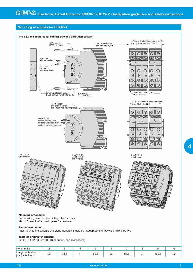
Mounting examples for ESX10-T
5 ESX10-TAwith busbars
5 ESX10-TBwith busbarsand jumpers
12.5 x n = width of protector blocke. g. 12.5 x 5 = 62.5insert busbars
and protection slidesto be flush with housing sides
insert signalbars to be flush withhousing and place themcentrally over the contacts
LINE+ busbarX22261102 grey
0 V busbarX22261102 grey
signal barX22200503 grey
orjumperX22200513 grey
remove protection againstbrush contact from bottom side
(12.5 x n)-3 = length of busbars ± 0.5e. g. (12.5 x 5)-3 = 59.5 ± 0.5
insert protection againstbrush contact
continuous busbar500 mm length, cut
5 ESX10-TDwith busbars
GE
RM
AN
YG
ER
MA
NY
The ESX10-T features an integral power distribution system.
Mounting procedure: Before wiring insert busbars into protector block.Max. 10 insertion/removal cycles for busbars.
Recommendation:After 10 units the busbars and signal busbars should be interrupted and receive a new entry live
Table of lengths for busbars (X 222 611 02 / X 222 005 03 or cut off, see accessories)
No. of units 2 3 4 5 6 7 8 9 10
Length of busbar[mm] ± 0.5 mm
22 34.5 47 59.5 72 84.5 97 109.5 122

Electronic Circuit Protector ESX10-T.-DC 24 V / Installation guidelines and safety instructions
www.e-t-a.de
Electronic Circuit Protector ESX10-T.-DC 24 V / Installation guidelines and safety instructions
171610
4
power supplyDC 24 V
+24V
0V
- line entry
load
+ - + - + -
+ - + - + -
load load
ESX10-TA-100
+ line entry
terminals forbusbars
screwterminals
LINE+ busbar(X 222 611 02 or X 222 611 xx)
0 V busbar(X 222 611 02 or X 222 611 xx)
1LINE+
1LINE+
1LINE+
ESX10-TA-100 ESX10-TA-100
3 0V
3 0V 3 0V 3 0V
3 0V3 0V
2 LOAD+ 2 LOAD+ 2 LOAD+
Connection diagrams and application examples ESX10-T…
Signal contacts are shown in OFF or fault condition.
ESX10-TA-100
ESX10-TB-101
group signalling (series connection)
+ line entry+ line entry for the SI
- line entry
power supplyDC 24 V
LINE + busbar(X 222 611 02 or X 222 611 xx)
group signallingby means of an signal lamp
jumpers (X 222 005 13)are staggered
0 V busbar(X 222 611 02 or X 222 611 xx)
+24V
0V
load load load
13
1LINE+
14
ESX10-TB-101
2 LOAD+
13
1LINE+
14 13
1LINE+
14
ESX10-TB-101
2 LOAD+
ESX10-TB-101
2 LOAD+
Connection diagrams and application examples ESX10-T

www.e-t-a.de
Electronic Circuit Protector ESX10-T.-DC 24 V / Installation guidelines and safety instructions
1716 11
4
Electronic Circuit Protector ESX10-T.-DC 24 V / Installation guidelines and safety instructions
ESX10-TB-102
Single signalling with common line entry
ESX10-TB-124
Single signalling with common reset
power supplyDC 24 V
+24 V
0V
+ line entry
- line entry
2 LOAD+
ESX10-TB-124
2 LOAD+
ESX10-TB-124
2 LOAD+
ESX10-TB-124
load load load
signal busbar (X 222 005 03) for common reset
0 V busbar(X 222 611 02 or X 222 611 xx)
LINE+ busbar(X 222 611 02 or X 222 611 xx)
single signalling per wayby means of an LED
22
1LINE+
RE SF23 22
1LINE+
RE SF23 22
1LINE+
RE SF23
resetbutton
power supplyDC 24 V
+24 V
0 V
+ line entry
+ line entryfor the SI
- line entry
11
1LINE+
12 11
1LINE+
12 11
1LINE+
12
2 LOAD+
ESX10-TB-102
3 0V
3 0V 3 0V 3 0V
3 0V 3 0V
2 LOAD+
ESX10-TB-102
2 LOAD+
ESX10-TB-102
load
+ - + - + -
+ - + - + -
load load
signal busbar (X 222 005 03) for common line entry
0 V busbar(X 222 611 02 or X 222 611 xx)
LINE+ busbar(X 222 611 02 or X 222 611 xx)
single signalling per wayby means of an LED
Connection diagrams and application examples ESX10-T
ESX10-T.-DC 24 V- Accessories / Installation guidelines and safety instructions
www.e-t-a.de
Electronic Circuit Protector ESX10-T.-DC 24 V / Installation guidelines and safety instructions
171612
4
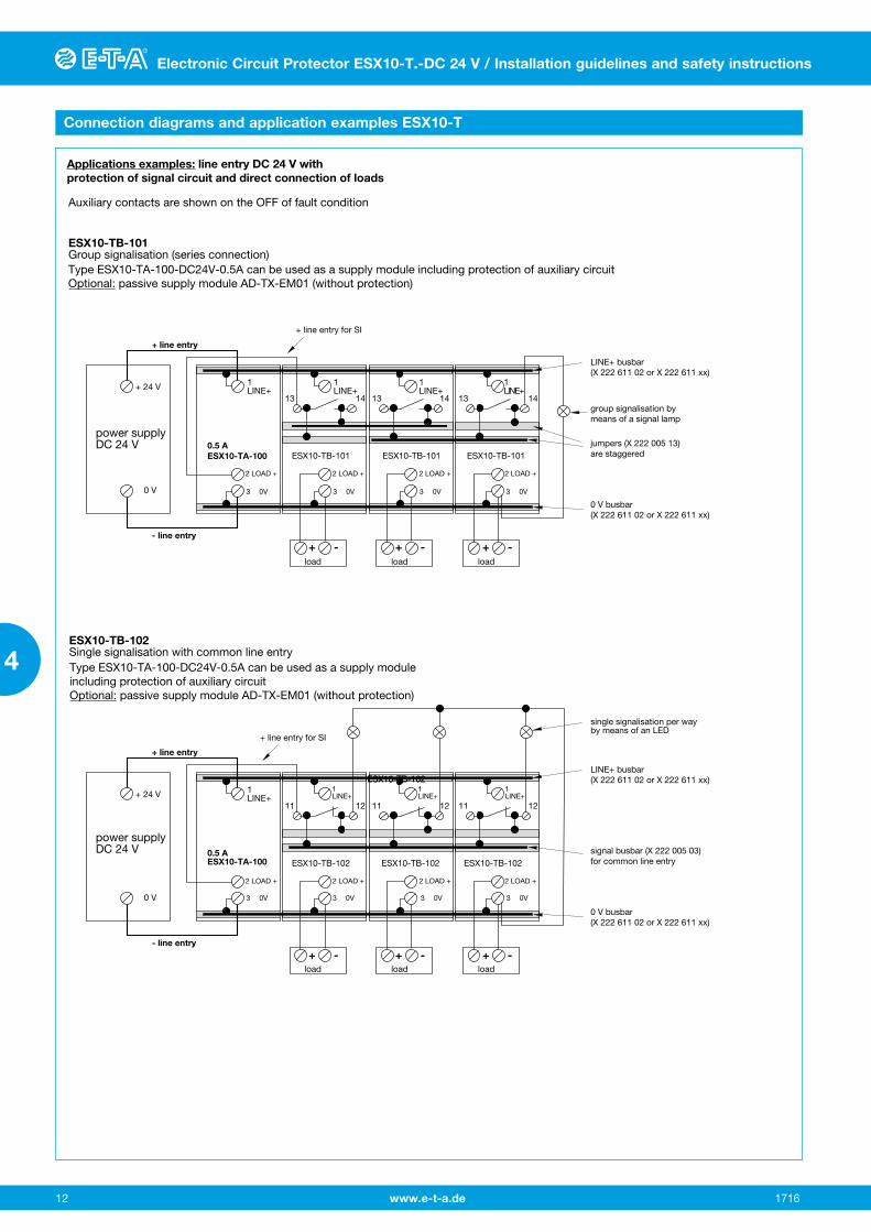
Applications examples: line entry DC 24 V with protection of signal circuit and direct connection of loads
Auxiliary contacts are shown on the OFF of fault condition
ESX10-TB-101Group signalisation (series connection)
power supplyDC 24 V
+ 24 V
0 V
- line entry
0.5 AESX10-TA-100
1LINE+
1LINE+
1LINE+
1LINE+
2 LOAD + 2 LOAD + 2 LOAD + 2 LOAD +
3 0V
3 0V 3 0V 3 0V 3 0V
3 0V 3 0V 3 0V
13 13 1314 14 14
+ line entry
ESX10-TB-101 ESX10-TB-101 ESX10-TB-101
load load load
+ line entry for SI
LINE+ busbar(X 222 611 02 or X 222 611 xx)
jumpers (X 222 005 13)are staggered
group signalisation bymeans of a signal lamp
0 V busbar(X 222 611 02 or X 222 611 xx)
power supplyDC 24 V
+ 24 V
0 V
- line entry
0.5 AESX10-TA-100
1LINE+
1LINE+
1LINE+
1LINE+
2 LOAD + 2 LOAD + 2 LOAD + 2 LOAD +
11 11 1112 12 12
+ line entry
ESX10-TB-102 ESX10-TB-102 ESX10-TB-102
load load load
+ line entry for SI
LINE+ busbar(X 222 611 02 or X 222 611 xx)
signal busbar (X 222 005 03) for common line entry
0 V busbar(X 222 611 02 or X 222 611 xx)
ESX10-TB-102Single signalisation with common line entryType ESX10-TA-100-DC24V-0.5A can be used as a supply moduleincluding protection of auxiliary circuitOptional: passive supply module AD-TX-EM01 (without protection)
single signalisation per wayby means of an LED
Type ESX10-TA-100-DC24V-0.5A can be used as a supply module including protection of auxiliary circuitOptional: passive supply module AD-TX-EM01 (without protection)
ESX10-TB-102ESX10-TB-102
+ - + -+ -
+ - + -+ -
Connection diagrams and application examples ESX10-T

www.e-t-a.de
ESX10-T.-DC 24 V- Accessories / Installation guidelines and safety instructions
1716 13
4
Electronic Circuit Protector ESX10-T.-DC 24 V / Installation guidelines and safety instructions
Accessories
Description
The ESX10-T features an integral power distribution system. The following wiring modes are possible with various pluggable current and signal busbars:
l LINE +(DC 24 V)l 0 V Caution: The electronic devices ESX10-T require a 0 V connectionl signal contactsl reset inputs
Busbars for LINE+ and 0 V max. load with one line entry Imax 50 A (recommended: centre line entry) max. load with two line entries Imax 63 A grey insulation, length: 500 mm X 222 611 02
Busbars for LINE+ and 0 V grey insulation max. number of plug-on operations 10:
X 222 611 22 (2-unit-block ESX10-T) length: 22 mm X 222 611 34 (3-unit-block ESX10-T) length: 34.5 mm X 222 611 47 (4-unit-block ESX10-T) length: 47 mm X 222 611 59 (5-unit-block ESX10-T) length: 59.5 mm packing unit: 10 pcs
X 222 611 72 (6-unit-block ESX10-T) length: 72 mm X 222 611 97 (8-unit-block ESX10-T) length: 97 mm X 222 611 12 (10-unit-block ESX10-T) length: 122 mm packing unit: 4 pcs
Signal busbars for signal contacts and reset inputs suitable for signal busbar ESX10-TB-... max. load with one line entry with one series connection of signal contacts Imax grey insulation, length: 500 mm X 222 005 03
Jumpers for signal contacts suitable for jumper ESX10-TB-... grey insulation, length: 21 mm X 222 005 13 packing unit: 10 pcs
Insulated wire bridge optional as jumper for ESX10-TB-101.../ESX10-TD-101... for group signalisation (series connection) X 223 108 01 packing unit: 10 pcs
7.50.295
Connector bus link –K10suitable for auxiliary contacts (series connection)X 210 589 02 (1.5 mm2, brown),
~2.
76
50 pin lugs toDIN 46230tinned copper
ø2.5.099
~70
www.e-t-a.de
ESX10-T.-DC 24 V- Accessories / Installation guidelines and safety instructions
1716 14
4
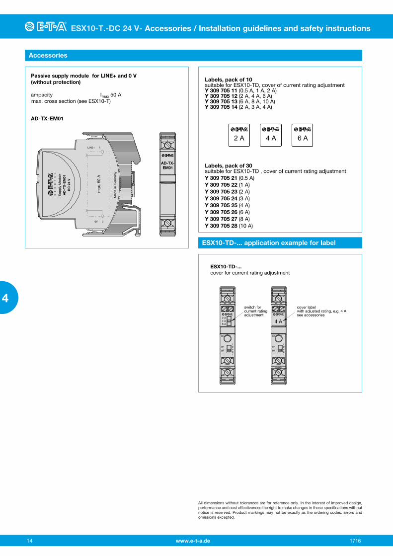
Labels, pack of 10suitable for ESX10-TD, cover of current rating adjustmentY 309 705 11 (0.5 A, 1 A, 2 A)Y 309 705 12 (2 A, 4 A, 6 A)Y 309 705 13 (6 A, 8 A, 10 A)Y 309 705 14 (2 A, 3 A, 4 A)
Labels, pack of 30suitable for ESX10-TD , cover of current rating adjustmentY 309 705 21 (0.5 A)Y 309 705 22 (1 A)Y 309 705 23 (2 A)Y 309 705 24 (3 A)Y 309 705 25 (4 A)Y 309 705 26 (6 A)Y 309 705 27 (8 A)Y 309 705 28 (10 A)
2 A 4 A 6 A
Accessories
ESX10-TD-... application example for label
switch for current ratingadjustment
cover labelwith adjusted rating, e.g. 4 Asee accessories
ESX10-TD-...cover for current rating adjustment
xx xx
2 A4 A6 A
ok
onreset
off
2 LOAD+
xx xx
ok
onreset
off
2 LOAD+
4 A
All dimensions without tolerances are for reference only. In the interest of improved design, performance and cost effectiveness the right to make changes in these specifications without notice is reserved. Product markings may not be exactly as the ordering codes. Errors and omissions excepted.
Passive supply module for LINE+ and 0 V (without protection)
ampacity Imax 50 A max. cross section (see ESX10-T)
AD-TX-EM01
max
. 50
A
LINE+ 1
0V 3
Sup
ply
Mod
ule
AD
-TX
-EM
01D
C 2
4 V
Mad
e in
Ger
man
y
AD-TX-EM01
GE
RM
AN
Y