Embed Size (px)
Citation preview
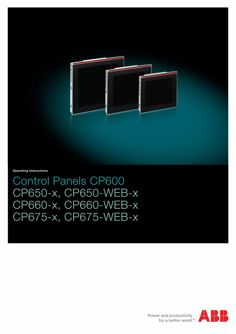
Control Panels CP600CP650-x, CP650-WEB-xCP660-x, CP660-WEB-xCP675-x, CP675-WEB-x
Operating Instructions
Operating Instructions 1 CP650, CP660, CP675
Content
Introduction ........................................................................................................................ 3
Before You Start ................................................................................................................ 4
Safety Notices........................................................................................................................... 4
Markups .................................................................................................................................... 4
Product Overview .............................................................................................................. 5
Standards and Approvals ................................................................................................. 6
Product Identification ............................................................................................................... 6
Technical Specifications .......................................................................................................... 7
Environmental Conditions ....................................................................................................... 7
Electromagnetic Compatibility (EMC) ..................................................................................... 8
Durability Information .............................................................................................................. 9
Technical Data ................................................................................................................. 10
Dimensions ............................................................................................................................. 11
Installation Environment ........................................................................................................ 12
Applying the Rectangular Gasket ......................................................................................... 12
Installation Procedure ............................................................................................................ 13
Connections ..................................................................................................................... 14
Serial Ports ............................................................................................................................. 14
Ethernet Port .......................................................................................................................... 16
Power Supply, Grounding and Shielding ...................................................................... 17
AUX Port ........................................................................................................................... 19
Battery .............................................................................................................................. 20
Cleaning Faceplates ........................................................................................................ 21
Getting Started ................................................................................................................. 22
Operating Instructions 2 CP650, CP660, CP675
System Settings ............................................................................................................... 23
Dedicated LED Indicators ............................................................................................... 25
Unpacking and Packing Instructions ............................................................................. 26
Operating Instructions 3 CP650, CP660, CP675
Introduction
The operational guidelines described below is information which relates to the device, place of employ-ment, transportation, storage, assembly, use and maintenance.
The products have been designed for use in an industrial environment in compliance with the 2004/108/CE directive.
The products have been designed in compliance with:
EN 61000-6-4
EN 55011 Class A
EN 61000-6-2
EN 61000-4-2, EN 61000-4-3, EN 61000-4-4, EN 61000-4-5, EN 61000-4-6
The installation of these devices into the residential, commercial and light-industrial environments is al-lowed only in the case that special measures are taken in order to get the conformity to IEC-61000-6.3.
The products are in compliance with the restrictions on Certain Hazardous Substances (RoHS) Directive 2002/95/EC.
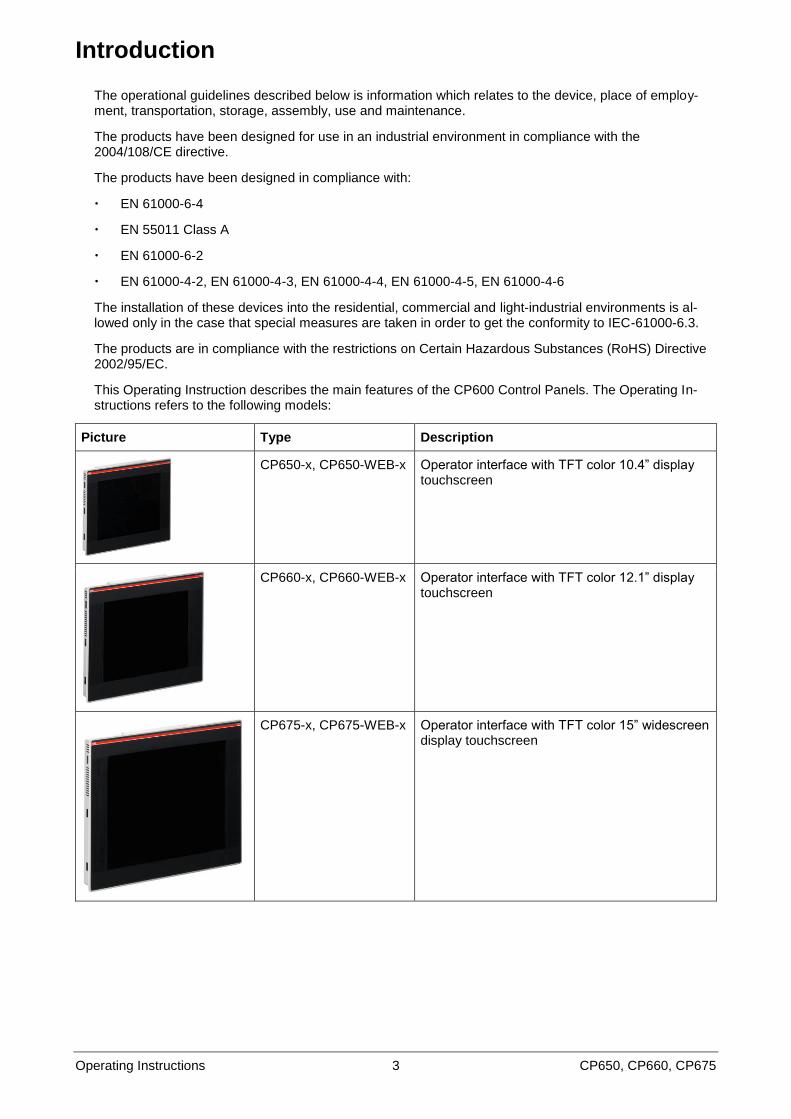
This Operating Instruction describes the main features of the CP600 Control Panels. The Operating In-structions refers to the following models:
Picture Type Description
CP650-x, CP650-WEB-x Operator interface with TFT color 10.4” display touchscreen
CP660-x, CP660-WEB-x Operator interface with TFT color 12.1” display touchscreen
CP675-x, CP675-WEB-x Operator interface with TFT color 15” widescreen display touchscreen
Operating Instructions 4 CP650, CP660, CP675
Before You Start
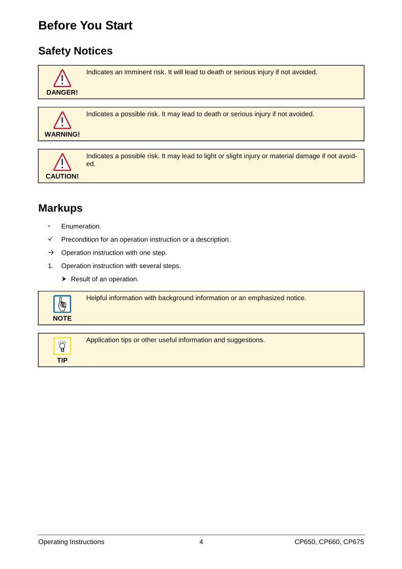
Safety Notices
DANGER!
Indicates an imminent risk. It will lead to death or serious injury if not avoided.
WARNING!
Indicates a possible risk. It may lead to death or serious injury if not avoided.
CAUTION!
Indicates a possible risk. It may lead to light or slight injury or material damage if not avoid-ed.
Markups
Enumeration.
Precondition for an operation instruction or a description.
Operation instruction with one step.
1. Operation instruction with several steps.
Result of an operation.
NOTE
Helpful information with background information or an emphasized notice.
TIP
Application tips or other useful information and suggestions.
Operating Instructions 5 CP650, CP660, CP675
Product Overview
The Control Panels combine state-of-the-art features and top performance with an oustanding design. They are the ideal choice for all demanding HMI applications including factory and building automation.
These Control Panels have been designed to run the PB610 Panel Builder 600 software.
PB610 Panel Builder 600 Runtime included. Full compatibility with PB610 Panel Builder 600.
Full vector graphic support. Native support of SVG graphic objects. Transparency and alpha blend-ing.
Full object dynamics: Control visibility and transparency, move, resize, rotate any object on screen. Change properties of basic and complex objects.
Truetype fonts.
Multilanguage applications. Easily create and manage your applications in multiple languages to meet global requirements. Far East languages are supported. Tools available in PB610 Panel Builder 600 support easy third-party translations and help reducing development and maintenance costs of the application.
Data display in numerical, text, bargraph, analog gauges and graphic image formats.
Rich set of state-of-the-art HMI features: Data acquisition, alarm handling, scheduler and timed ac-tions (daily and weekly schedulers, exception dates), recipes, users and passwords, e-mail and RSS feeds, rotating menus.
Includes support for a wide range of communication drivers.
Multiple drivers communication capability.
Remote monitoring and control. Client-Server functionality.
Simulation with PB610 Panel Builder 600.
Powerful scripting language for automating HMI applications. Script debugging improves efficiency in application development.
Rich gallery of vector symbols and objects.
Project & page templates.
Optional plug-in modules for fieldbus systems, networks and controllers.
Operating Instructions 6 CP650, CP660, CP675
Standards and Approvals
The Control Panels have been designed for installation and use in an industrial environment in compli-ance with the 2004/108/EC EMC Directive and with the following harmonized standards:
EN 61000-6-4
EN 61000-6-2
In compliance with the above regulations the products are CE marked.
The installation of these devices into the residential, commercial and light-industrial environments is al-lowed only in the case that special measures are taken in order to get the conformity to EN 61000-6-3.
Product Identification
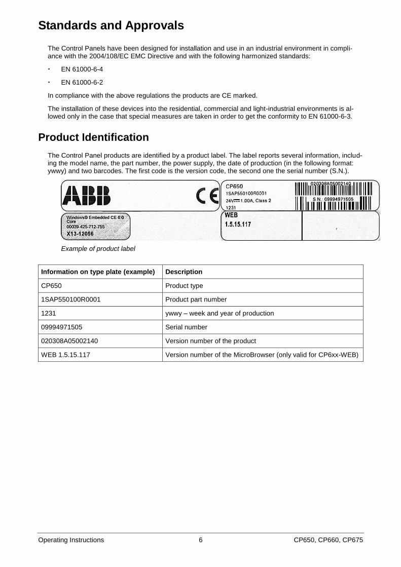
The Control Panel products are identified by a product label. The label reports several information, includ-ing the model name, the part number, the power supply, the date of production (in the following format: ywwy) and two barcodes. The first code is the version code, the second one the serial number (S.N.).
Example of product label
Information on type plate (example) Description
CP650 Product type
1SAP550100R0001 Product part number
1231 ywwy – week and year of production
09994971505 Serial number
020308A05002140 Version number of the product
WEB 1.5.15.117 Version number of the MicroBrowser (only valid for CP6xx-WEB)
Operating Instructions 7 CP650, CP660, CP675
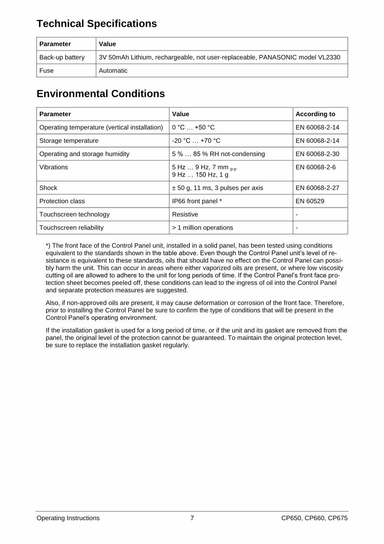
Technical Specifications
Parameter Value
Back-up battery 3V 50mAh Lithium, rechargeable, not user-replaceable, PANASONIC model VL2330
Fuse Automatic
Environmental Conditions
Parameter Value According to
Operating temperature (vertical installation) 0 °C … +50 °C EN 60068-2-14
Storage temperature -20 °C … +70 °C EN 60068-2-14
Operating and storage humidity 5 % … 85 % RH not-condensing EN 60068-2-30
Vibrations 5 Hz … 9 Hz, 7 mm p-p 9 Hz … 150 Hz, 1 g
EN 60068-2-6
Shock ± 50 g, 11 ms, 3 pulses per axis EN 60068-2-27
Protection class IP66 front panel * EN 60529
Touchscreen technology Resistive -
Touchscreen reliability > 1 million operations -
*) The front face of the Control Panel unit, installed in a solid panel, has been tested using conditions equivalent to the standards shown in the table above. Even though the Control Panel unit‟s level of re-sistance is equivalent to these standards, oils that should have no effect on the Control Panel can possi-bly harm the unit. This can occur in areas where either vaporized oils are present, or where low viscosity cutting oil are allowed to adhere to the unit for long periods of time. If the Control Panel‟s front face pro-tection sheet becomes peeled off, these conditions can lead to the ingress of oil into the Control Panel and separate protection measures are suggested.
Also, if non-approved oils are present, it may cause deformation or corrosion of the front face. Therefore, prior to installing the Control Panel be sure to confirm the type of conditions that will be present in the Control Panel‟s operating environment.
If the installation gasket is used for a long period of time, or if the unit and its gasket are removed from the panel, the original level of the protection cannot be guaranteed. To maintain the original protection level, be sure to replace the installation gasket regularly.
Operating Instructions 8 CP650, CP660, CP675
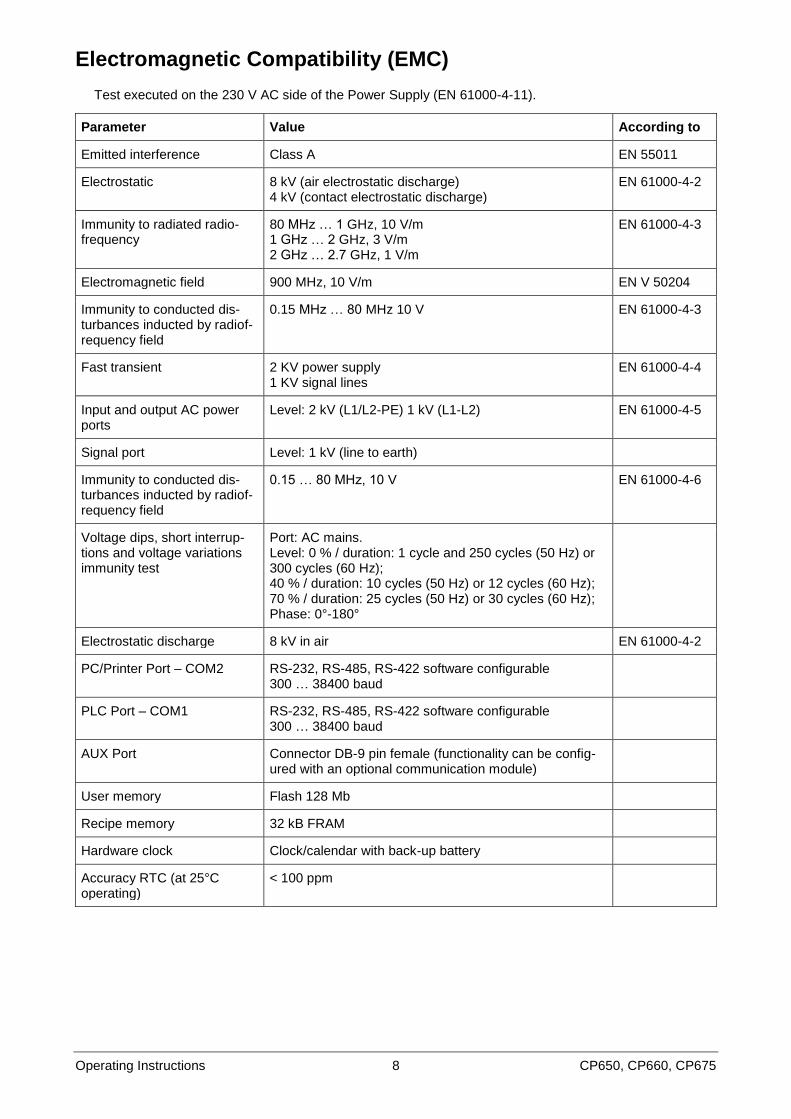
Electromagnetic Compatibility (EMC)
Test executed on the 230 V AC side of the Power Supply (EN 61000-4-11).
Parameter Value According to
Emitted interference Class A EN 55011
Electrostatic 8 kV (air electrostatic discharge) 4 kV (contact electrostatic discharge)
EN 61000-4-2
Immunity to radiated radio-frequency
80 MHz … 1 GHz, 10 V/m 1 GHz … 2 GHz, 3 V/m 2 GHz … 2.7 GHz, 1 V/m
EN 61000-4-3
Electromagnetic field 900 MHz, 10 V/m EN V 50204
Immunity to conducted dis-turbances inducted by radiof-requency field
0.15 MHz … 80 MHz 10 V EN 61000-4-3
Fast transient 2 KV power supply 1 KV signal lines
EN 61000-4-4
Input and output AC power ports
Level: 2 kV (L1/L2-PE) 1 kV (L1-L2) EN 61000-4-5
Signal port Level: 1 kV (line to earth)
Immunity to conducted dis-turbances inducted by radiof-requency field
0.15 … 80 MHz, 10 V EN 61000-4-6
Voltage dips, short interrup-tions and voltage variations immunity test
Port: AC mains. Level: 0 % / duration: 1 cycle and 250 cycles (50 Hz) or 300 cycles (60 Hz); 40 % / duration: 10 cycles (50 Hz) or 12 cycles (60 Hz); 70 % / duration: 25 cycles (50 Hz) or 30 cycles (60 Hz); Phase: 0°-180°
Electrostatic discharge 8 kV in air EN 61000-4-2
PC/Printer Port – COM2 RS-232, RS-485, RS-422 software configurable 300 … 38400 baud
PLC Port – COM1 RS-232, RS-485, RS-422 software configurable 300 … 38400 baud
AUX Port Connector DB-9 pin female (functionality can be config-ured with an optional communication module)
User memory Flash 128 Mb
Recipe memory 32 kB FRAM
Hardware clock Clock/calendar with back-up battery
Accuracy RTC (at 25°C operating)
< 100 ppm
Operating Instructions 9 CP650, CP660, CP675
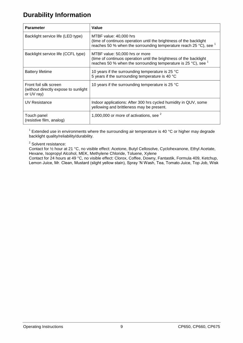
Durability Information
Parameter Value
Backlight service life (LED type) MTBF value: 40,000 hrs (time of continuos operation until the brightness of the backlight reaches 50 % when the sorrounding temperature reach 25 °C), see
1
Backlight service life (CCFL type) MTBF value: 50,000 hrs or more (time of continuos operation until the brightness of the backlight reaches 50 % when the sorrounding temperature is 25 °C), see
1
Battery lifetime 10 years if the surrounding temperature is 25 °C 5 years if the surrounding temperature is 40 °C
Front foil silk screen (without directly expose to sunlight or UV ray)
10 years if the surrounding temperature is 25 °C
UV Resistance Indoor applications: After 300 hrs cycled humidity in QUV, some yellowing and brittleness may be present.
Touch panel (resistive film, analog)
1,000,000 or more of activations, see 2
1 Extended use in environments where the surrounding air temperature is 40 °C or higher may degrade
backlight quality/reliability/durability.
2 Solvent resistance:
Contact for ½ hour at 21 °C, no visible effect: Acetone, Butyl Cellosolve, Cyclohexanone, Ethyl Acetate, Hexane, Isopropyl Alcohol, MEK, Methylene Chloride, Toluene, Xylene Contact for 24 hours at 49 °C, no visible effect: Clorox, Coffee, Downy, Fantastik, Formula 409, Ketchup, Lemon Juice, Mr. Clean, Mustard (slight yellow stain), Spray „N Wash, Tea, Tomato Juice, Top Job, Wisk
Operating Instructions 10 CP650, CP660, CP675
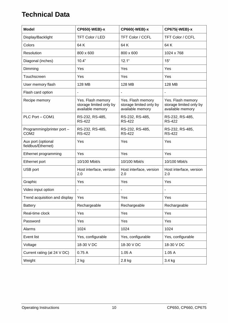
Technical Data
Model CP650(-WEB)-x CP660(-WEB)-x CP675(-WEB)-x
Display/Backlight TFT Color / LED TFT Color / CCFL TFT Color / CCFL
Colors 64 K 64 K 64 K
Resolution 800 x 600 800 x 600 1024 x 768
Diagonal (inches) 10.4” 12.1“ 15“
Dimming Yes Yes Yes
Touchscreen Yes Yes Yes
User memory flash 128 MB 128 MB 128 MB
Flash card option - - -
Recipe memory Yes. Flash memory storage limited only by available memory
Yes. Flash memory storage limited only by available memory
Yes. Flash memory storage limited only by available memory
PLC Port – COM1 RS-232, RS-485, RS-422
RS-232, RS-485, RS-422
RS-232, RS-485, RS-422
Programming/printer port – COM2
RS-232, RS-485, RS-422
RS-232, RS-485, RS-422
RS-232, RS-485, RS-422
Aux port (optional fieldbus/Ethernet)
Yes Yes Yes
Ethernet programming Yes Yes Yes
Ethernet port 10/100 Mbit/s 10/100 Mbit/s 10/100 Mbit/s
USB port Host interface, version 2.0
Host interface, version 2.0
Host interface, version 2.0
Graphic Yes Yes Yes
Video input option - - -
Trend acquisition and display Yes Yes Yes
Battery Rechargeable Rechargeable Rechargeable
Real-time clock Yes Yes Yes
Password Yes Yes Yes
Alarms 1024 1024 1024
Event list Yes, configurable Yes, configurable Yes, configurable
Voltage 18-30 V DC 18-30 V DC 18-30 V DC
Current rating (at 24 V DC) 0.75 A 1.05 A 1.05 A
Weight 2 kg 2.8 kg 3.4 kg
Operating Instructions 11 CP650, CP660, CP675
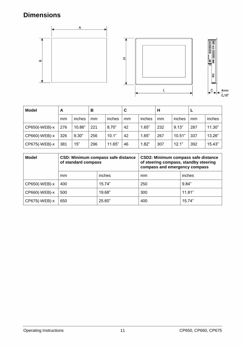
Dimensions
Model A B C H L
mm inches mm inches mm inches mm inches mm inches
CP650(-WEB)-x 276 10.86” 221 8.70” 42 1.65” 232 9.13” 287 11.30”
CP660(-WEB)-x 326 9.30” 256 10.1” 42 1.65” 267 10.51” 337 13.26”
CP675(-WEB)-x 381 15” 296 11.65” 46 1.82” 307 12.1” 392 15.43”
Model CSD: Minimum compass safe distance of standard compass
CSD2: Minimum compass safe distance of steering compass, standby steering compass and emergency compass
mm inches mm inches
CP650(-WEB)-x 400 15.74” 250 9.84”
CP660(-WEB)-x 500 19.68” 300 11.81”
CP675(-WEB)-x 650 25.60” 400 15.74”
Operating Instructions 12 CP650, CP660, CP675
Installation Environment
The equipment is not intended for continuous exposure to direct sunlight. This might accelerate the aging process of the front panel film.
The equipment is not intended for installation in contact with corrosive chemical compounds. Check the resistance of the front panel film to a specific compound before installation.
Do not use tools of any kind (screwdrivers etc.) to operate the keyboard of the panel or the touchscreen.
In order to meet the front panel protection classifications, proper installation procedure must be followed:
The borders of the cutout must be flat.
The cutout for the panel must be of the dimensions indicated in this manual.
Screw up each fixing screw until the plastic bezel corner get in contact with the panel.
The IP66 is guaranteed only if:
Maximum deviation from the plane surface to the cut-out: Ø 0.5 mm
Thickness of the plate the equiment is mounted: 1.5 mm to 6 mm
Maximum surface roughness where the gasket is applied: Ø 120 µm
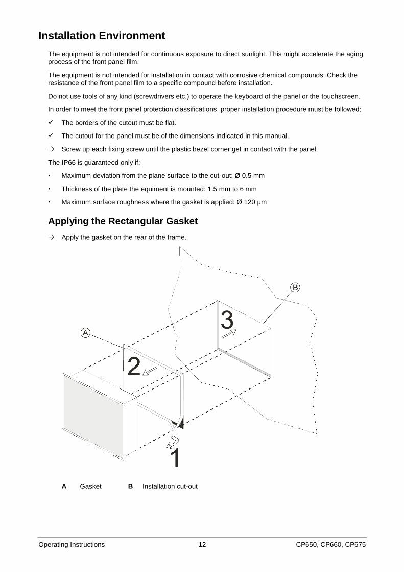
Applying the Rectangular Gasket
Apply the gasket on the rear of the frame.
A Gasket B Installation cut-out
Operating Instructions 13 CP650, CP660, CP675
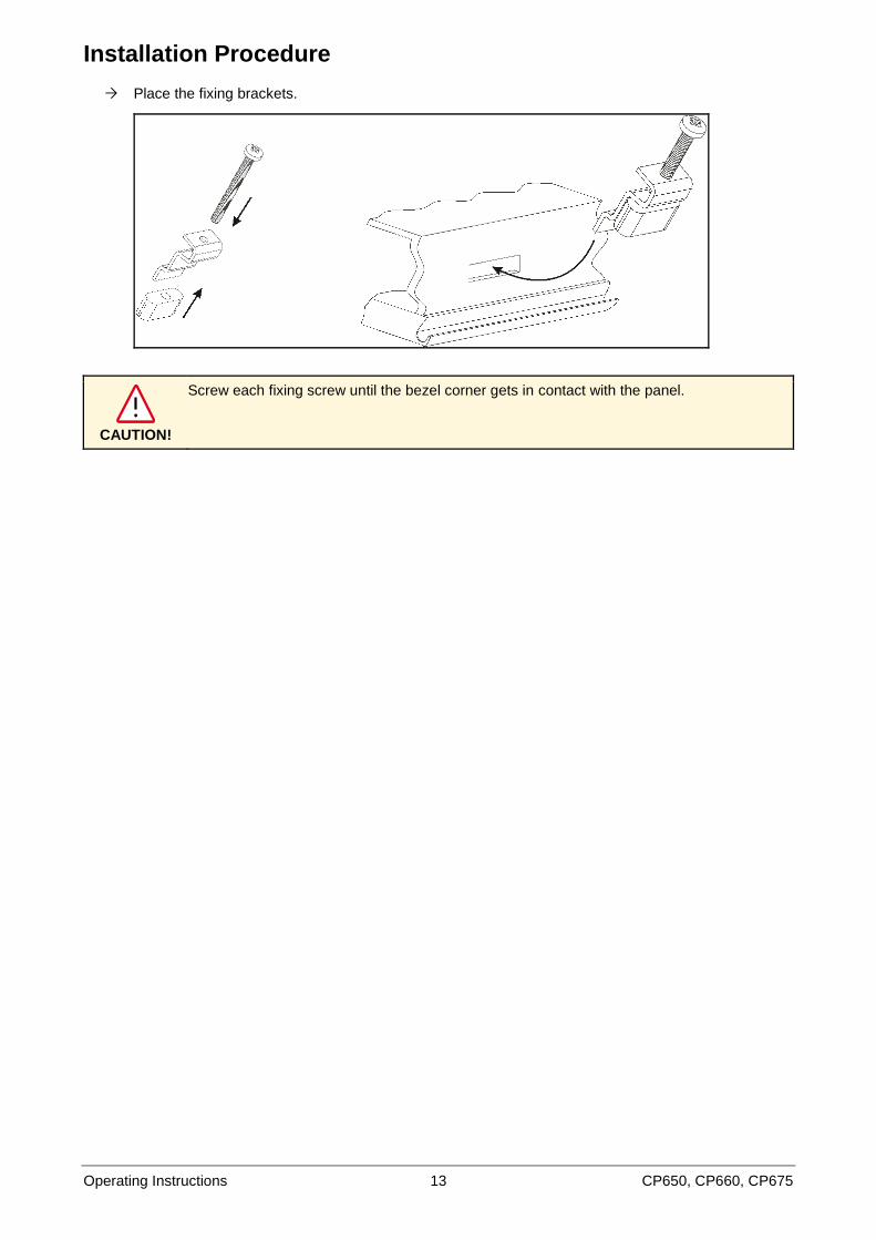
Installation Procedure
Place the fixing brackets.
CAUTION!
Screw each fixing screw until the bezel corner gets in contact with the panel.
Operating Instructions 14 CP650, CP660, CP675
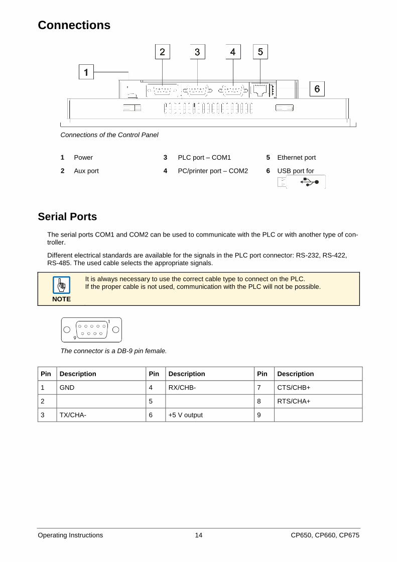
Connections
Connections of the Control Panel
1 Power 3 PLC port – COM1 5 Ethernet port
2 Aux port 4 PC/printer port – COM2 6 USB port for
Serial Ports
The serial ports COM1 and COM2 can be used to communicate with the PLC or with another type of con-troller.
Different electrical standards are available for the signals in the PLC port connector: RS-232, RS-422, RS-485. The used cable selects the appropriate signals.
NOTE
It is always necessary to use the correct cable type to connect on the PLC. If the proper cable is not used, communication with the PLC will not be possible.
The connector is a DB-9 pin female.
Pin Description Pin Description Pin Description
1 GND 4 RX/CHB- 7 CTS/CHB+
2 5 8 RTS/CHA+
3 TX/CHA- 6 +5 V output 9
Operating Instructions 15 CP650, CP660, CP675
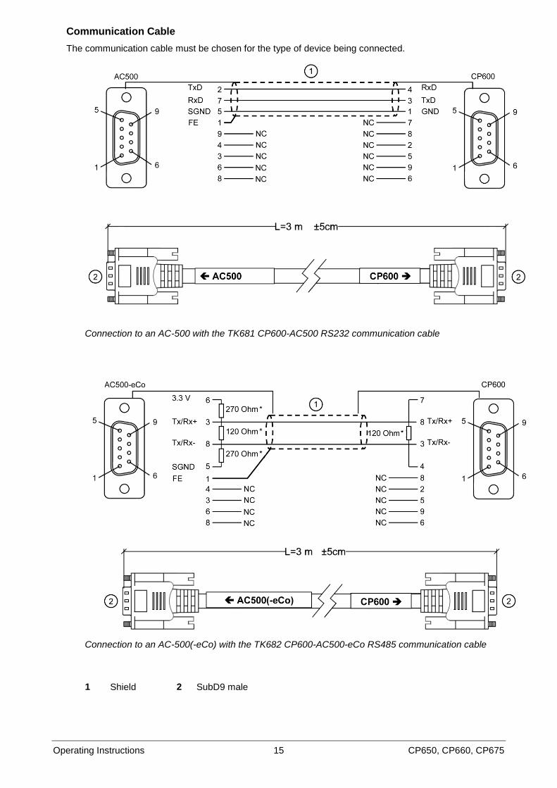
Communication Cable
The communication cable must be chosen for the type of device being connected.
Connection to an AC-500 with the TK681 CP600-AC500 RS232 communication cable
Connection to an AC-500(-eCo) with the TK682 CP600-AC500-eCo RS485 communication cable
1 Shield 2 SubD9 male
Operating Instructions 16 CP650, CP660, CP675
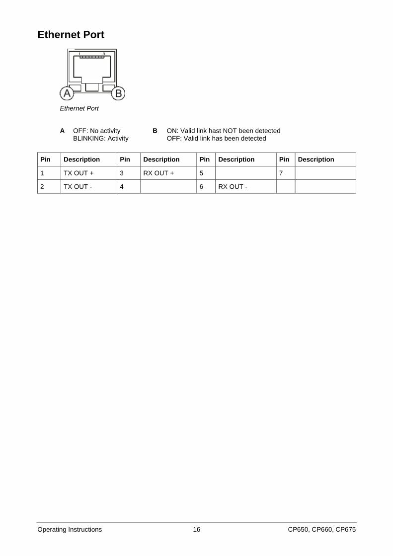
Ethernet Port
Ethernet Port
A OFF: No activity BLINKING: Activity
B ON: Valid link hast NOT been detected OFF: Valid link has been detected
Pin Description Pin Description Pin Description Pin Description
1 TX OUT + 3 RX OUT + 5 7
2 TX OUT - 4 6 RX OUT -
Operating Instructions 17 CP650, CP660, CP675
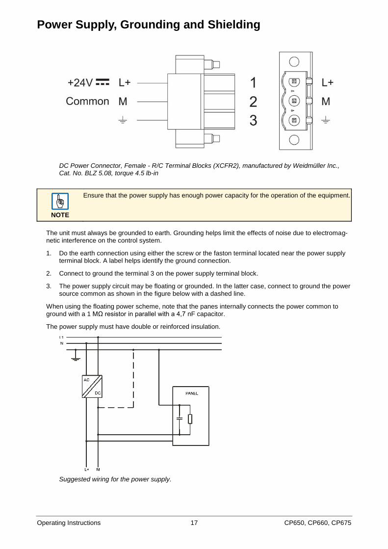
Power Supply, Grounding and Shielding
DC Power Connector, Female - R/C Terminal Blocks (XCFR2), manufactured by Weidmüller Inc., Cat. No. BLZ 5.08, torque 4.5 lb-in
NOTE
Ensure that the power supply has enough power capacity for the operation of the equipment.
The unit must always be grounded to earth. Grounding helps limit the effects of noise due to electromag-netic interference on the control system.
1. Do the earth connection using either the screw or the faston terminal located near the power supply terminal block. A label helps identify the ground connection.
2. Connect to ground the terminal 3 on the power supply terminal block.
3. The power supply circuit may be floating or grounded. In the latter case, connect to ground the power source common as shown in the figure below with a dashed line.
When using the floating power scheme, note that the panes internally connects the power common to ground with a 1 MΩ resistor in parallel with a 4,7 nF capacitor.
The power supply must have double or reinforced insulation.
Suggested wiring for the power supply.

Operating Instructions 18 CP650, CP660, CP675
All the electronic devices in the control system must be properly grounded. Grounding must be performed according to applicable regulations.
Operating Instructions 19 CP650, CP660, CP675
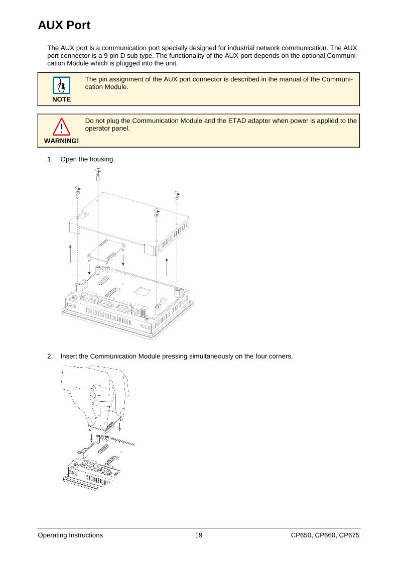
AUX Port
The AUX port is a communication port specially designed for industrial network communication. The AUX port connector is a 9 pin D sub type. The functionality of the AUX port depends on the optional Communi-cation Module which is plugged into the unit.
NOTE
The pin assignment of the AUX port connector is described in the manual of the Communi-cation Module.
WARNING!
Do not plug the Communication Module and the ETAD adapter when power is applied to the operator panel.
1. Open the housing.
2. Insert the Communication Module pressing simultaneously on the four corners.
Operating Instructions 20 CP650, CP660, CP675
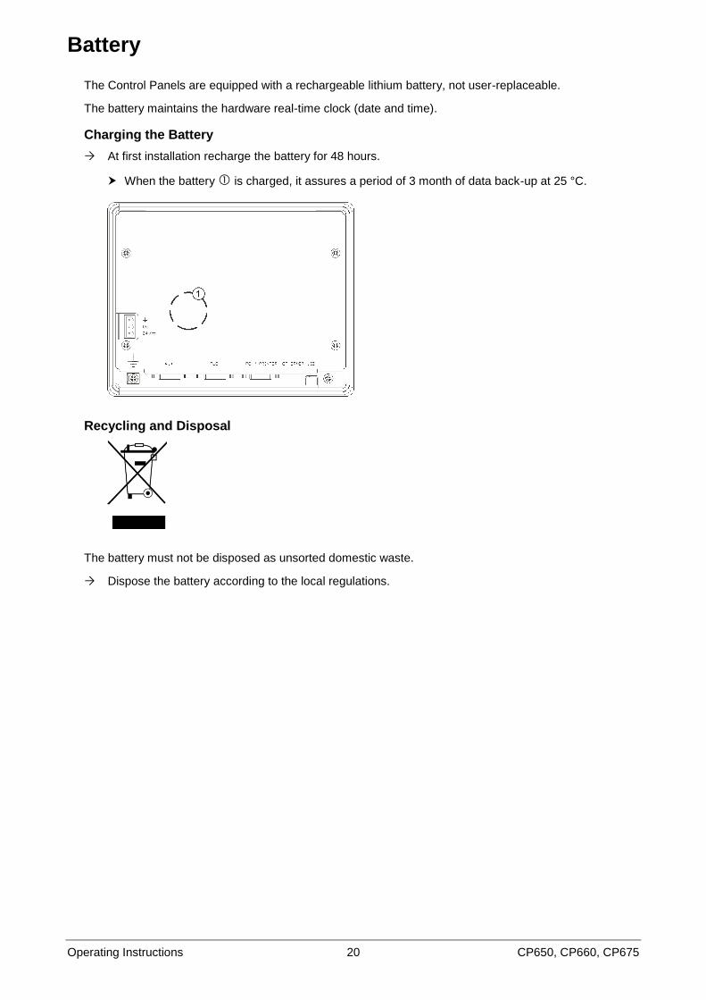
Battery
The Control Panels are equipped with a rechargeable lithium battery, not user-replaceable.
The battery maintains the hardware real-time clock (date and time).
Charging the Battery
At first installation recharge the battery for 48 hours.
When the battery is charged, it assures a period of 3 month of data back-up at 25 °C.
Recycling and Disposal
The battery must not be disposed as unsorted domestic waste.
Dispose the battery according to the local regulations.
Operating Instructions 21 CP650, CP660, CP675
Cleaning Faceplates
The equipment must be cleaned only with a soft cloth and neutral soap product. Do not use solvents.
Operating Instructions 22 CP650, CP660, CP675
Getting Started
The Control Panels must be programmed with the programming package PB610 Panel Builder 600.
The Control Panels are programmed via the Ethernet interface.
The Control Panel must be in configuration mode to be programmed.
To program a Control Panel connect the Control Panel to a PC running PB610 Panel Builder 600 software package.
The software package PB610 Panel Builder 600 is a WindowsTM
application and must be properly in-stalled. The Windows
TM environment is not included in the software package PB610 Panel Builder 600
and must already be installed on the PC.
PB610 Panel Builder 600 uses the PC Ethernet interface to communicate with the target device.
Make sure that the proper firewall policy is configured in order to allow PB610 Panel Builder 600 to access the network.
The version of the Panel Builder used must be compatible with the PB610 Panel Builder 600 Runtime version installed on the Control Panel to be programmed. Check with technical support for more infor-mation on compatibility between firmware and programming software.
Operating Instructions 23 CP650, CP660, CP675
System Settings
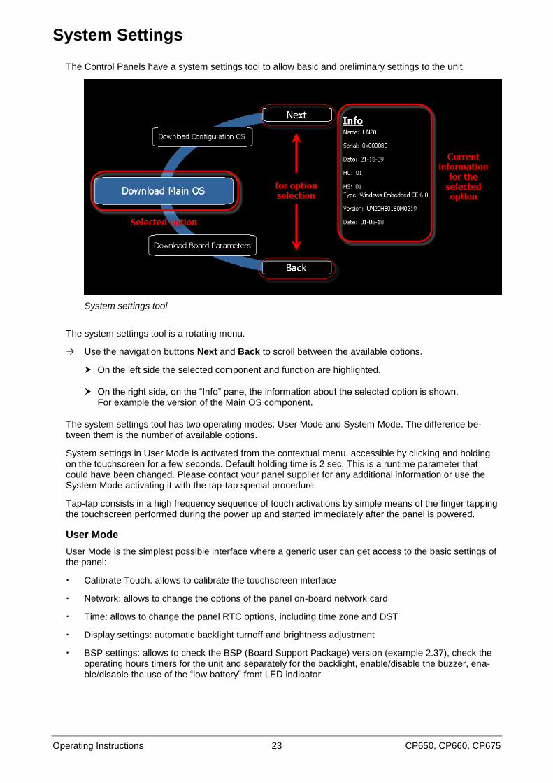
The Control Panels have a system settings tool to allow basic and preliminary settings to the unit.
System settings tool
The system settings tool is a rotating menu.
Use the navigation buttons Next and Back to scroll between the available options.
On the left side the selected component and function are highlighted.
On the right side, on the “Info” pane, the information about the selected option is shown. For example the version of the Main OS component.
The system settings tool has two operating modes: User Mode and System Mode. The difference be-tween them is the number of available options.
System settings in User Mode is activated from the contextual menu, accessible by clicking and holding on the touchscreen for a few seconds. Default holding time is 2 sec. This is a runtime parameter that could have been changed. Please contact your panel supplier for any additional information or use the System Mode activating it with the tap-tap special procedure.
Tap-tap consists in a high frequency sequence of touch activations by simple means of the finger tapping the touchscreen performed during the power up and started immediately after the panel is powered.
User Mode
User Mode is the simplest possible interface where a generic user can get access to the basic settings of the panel:
Calibrate Touch: allows to calibrate the touchscreen interface
Network: allows to change the options of the panel on-board network card
Time: allows to change the panel RTC options, including time zone and DST
Display settings: automatic backlight turnoff and brightness adjustment
BSP settings: allows to check the BSP (Board Support Package) version (example 2.37), check the operating hours timers for the unit and separately for the backlight, enable/disable the buzzer, ena-ble/disable the use of the “low battery” front LED indicator
Operating Instructions 24 CP650, CP660, CP675
System Mode
System Mode is the complete interface of the system settings tool where all options are available. Additionally to the options of the User Mode the following options are available:
Format Flash: allows to format the internal panel flash disk
Resize Image Area: allows to resize the flash portion reserved to store the splash screen image dis-played by the unit at power up; default settings are normally ok for all the units
Download Configuration OS: allows to check current version and upgrade the back-up operating sys-tem, see below in the next chapter for additional details
Download Main OS: allows to check current version and upgrade the main operating system, see be-low in the next chapter for additional details
Download Splash Image: allows changing the splash screen image displayed by the unit at power up; the image should be provide in a specific format. We suggest to update Splash Screen Image di-rectly from Studio software which supports this feature starting from V 1. 50
Download Bootloader: allows to check current version of the system boot loader and to upgrade it, see below for additional details
Download Main FPGA: allows to check current version and upgrade the main FPGA firmware, see below for additional details
Download Safe FPGA: allows to check current version and upgrade the back-up (safe) copy of the FPGA Firmware, see below for additional details
Download System Supervisor: allows to check current version and upgrade the system supervisor firmware responsible for RTC and power supply handling, see below for additional details
Operating Instructions 25 CP650, CP660, CP675
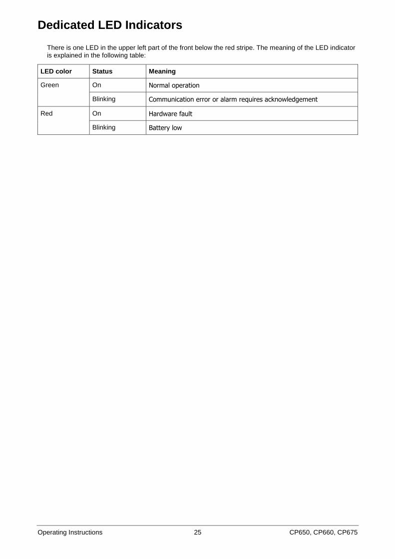
Dedicated LED Indicators
There is one LED in the upper left part of the front below the red stripe. The meaning of the LED indicator is explained in the following table:
LED color Status Meaning
Green On Normal operation
Blinking Communication error or alarm requires acknowledgement
Red On Hardware fault
Blinking Battery low
Operating Instructions 26 CP650, CP660, CP675
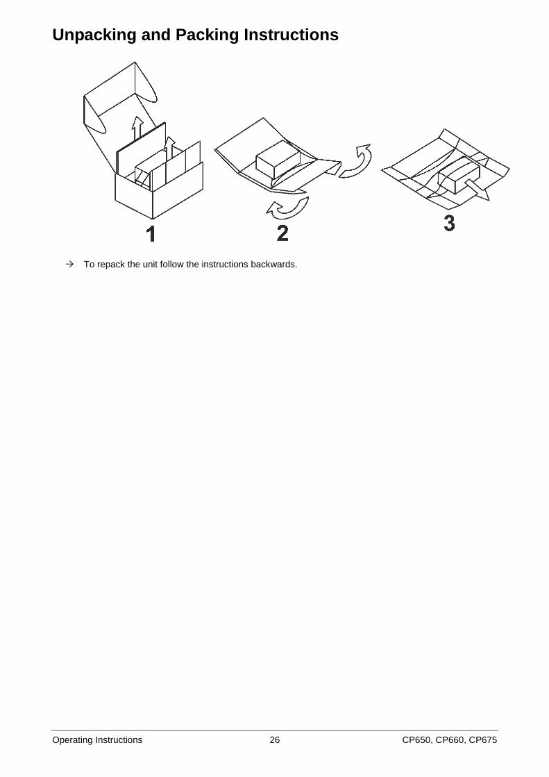
Unpacking and Packing Instructions
To repack the unit follow the instructions backwards.
Contact us
3AD
R05
9031
M02
03ABB Automation Products GmbHWallstadter Str. 59 68526 Ladenburg, Germany Phone: +49 62 21 701 1444 Fax: +49 62 21 701 1382 E-Mail: [email protected] www.abb.com/plc
Note:We reserve the right to make technical changes or modify the contents of this document without prior notice. With regard to purchase orders, the agreed particulars shall prevail. ABB AG does not accept any responsibility whatsoever for potential errors or possible lack of information in this document.
We reserve all rights in this document and in the subject matter and illustrations contained therein. Any reproduction, disclosure to third parties or utilization of its contents – in whole or in parts – is forbidden without prior written consent of ABB AG.
© Copyright 2011-2013 ABB.All rights reserved.Subject to alterations.