Embed Size (px)
Citation preview
Contents
Alcatel - High Vacuum Technology - User’s Manual ADP/ADS
ADP/ADSUser’s manual
1/3
Editi
on 0
4 - M
ay 9
8
A - Introduction
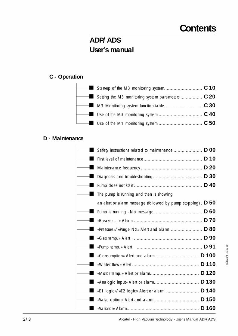
ADP/ADS Series One ............................................. A 10 The various versions of ADP Series One ...................... A 20 ADP/ADS Serie One Dry pumps
for semi-conductor’s industry ....................................... A 30 Types of monitoring systems ...................................... A 40 Dry pump operational principle ................................. A 50 The accessories ....................................................... A 60 Technical characteristics............................................. A 70
B - Start-up
Safety instructions .................................................... B 00 Unpacking / Storage ............................................... B 10 Positioning the pump in pumping installation ................. B 20 Installing anti-vibration pads........................................ B 30 Modular version - Layout .......................................... B 40 Filling the pump oil housings ...................................... B 50 Connection to the cooling circuit ............................... B 60 Inert gas purge connection (N2 plug) .......................... B 70 Nitrogen purge flow sensor ....................................... B 80 Connection to the pumping circuit ............................. B 90 Electropneumatic exhaust valve connection (withdrawal) B 100 Pump power supply ............................................... B 110 Water flowrate and gas purge according to processes... B 120 Checking the rotational direction .............................. B 130 Remote control plug connection (M3 monitoring) ......... B 140 Remote control plug connection (M1 monitoring) ......... B 141 RS 232 or RS 485 link wiring .................................. B 150 Use of the Serial link (Service centers) ........................ B 160 Installation of silencer heating kit ............................... B 170
Contents
Alcatel - High Vacuum Technology - User’s Manual ADP/ADS
ADP/ADSUser’s manual
2/3
Editi
on 0
4 - M
ay 9
8
C - Operation
D - Maintenance
Safety instructions related to maintenance ..................... D 00 First level of maintenance........................................... D 10 Maintenance frequency ............................................. D 20 Diagnosis and troubleshooting .................................... D 30 Pump does not start .................................................. D 40 The pump is running and then is showing
an alert or alarm message (followed by pump stopping) . D 50 Pump is running - No message .................................. D 60 «Breaker …» Alarm .................................................. D 70 «Pressure»/«Purge N2» Alert and alarm ....................... D 80 «Gas temp.» Alert .................................................. D 90 «Pump temp.» Alert ................................................. D 91 «Consumption» Alert and alarm ................................ D 100 «Water flow» Alert ................................................. D 110 «Motor temp.» Alert or alarm.................................... D 120 «Analogic input» Alert or alarm................................. D 130 «E1 logic»/«E2 logic» Alert or alarm ........................ D 140 «Valve option» Alert and alarm ................................ D 150 «Variator» Alarm..................................................... D 160
Start-up of the M3 monitoring system............................ C 10 Setting the M3 monitoring system parameters ................ C 20 M3 Monitoring system function table............................ C 30 Use of the M3 monitoring system ................................ C 40 Use of the M1 monitoring system ................................ C 50

Contents
Alcatel - High Vacuum Technology - User’s Manual ADP/ADS
ADP/ADSUser’s manual
3/3
Editi
on 0
4 - M
ay 9
8
Safety instructions concerning product installation, operation andmaintenance.
Our ALCATEL products are designed and tested to providemaximum safety. However, in order to obtain the best level ofsafety, the following must be observed:
- the user’s manual during product transport, installation, operationand maintenance.- the safety instructions signalled with the following symbol:
Symbol Meaning
Users of this equipment should be alert to level ofhazards identified by this symbol.
Warnings are used when failure to observe instructionsor precautions could result in significant damage toequipment, and/or in injury to humans.
E - Maintenanceinstructions
Maintenance precautions (Service centers) .................... E 10 Pump draining ......................................................... E 20 Silencer maintenance ................................................ E 30 Electropneumatic valve maintenance (withdrawal) ........... E 40 Freeing up the ADP .................................................. E 50

Alcatel - High Vacuum Technology - User’s Manual ADP/ADS
ADP/ADS Series One dry pumps
1/1
Dear Customer,
you have just purchased anAlcatel dry pump. We thankyou and are proud to includeyou in our customers.
This product has benefitedfrom Alcatel’s many years ofexperience in “semiconductor”processes and dry pumping.
For optimum performanceand to obtain full satisfactionfrom this equipment, werecommend that you studythis manual before any intervention on your pump,in particular, the chapter oninstallation and start up.
MANUAL REFERENCE : 100 448EDITION : 04 - May 1998
APPLICATIONS :• ALL “SEMICONDUCTORS” PROCESSESStripping, Etching, PECVD, LPCVD, MOCVD, Epitaxy, …• SCIENTIFIC RESEARCH
ADVANTAGES :Easily adaptable to processes - Tested design - Vertical pumping -Clean room compatible - Advanced monitoring system functions -Low noise level - Low operating cost - Easy maintenance andrepairs - Anti-vibration frame - Compact.
SPECIAL FEATURES :Multi-stage Roots technology - water-cooled multi-voltage motors -built-in monitoring system (remote optional) - anti-dust,sound-proof aesthetic covers, easily removed - incorporatedpurge line (N2) - Quick connection - Modular design andinterchangeable parts - Easy to transport - Network compatible.

Alcatel - High Vacuum Technology - User’s Manual ADP/ADS
Editi
on 0
3 - M
ay 9
7
A 10ADP/ADS Series One
1/1
Multi-stage pump withRoots technology
Sealed motor with liquidcooling
Genuinely dry pump
Vertical pumping
ReliabilityEasy maintenance
Pump designed for allprocesses
2 versions
- well-known technology- reliability
- no fan (clean room compatible)- safe : no gas leak- quiet- multi-voltage, bi-frequency 50/60 Hz
- guaranteed by design- guaranteed by testingResidual gas spectrum free from hydrocarbon peaks
MTBF > 50 000 hours- interchangeables parts- may be performed by user
- Several equipments are available for semi-conductor’sapplications, corrosives, CVD or clean processes
Standard or modular

Alcatel - High Vacuum Technology - User’s Manual ADP/ADS
Editi
on 0
3 - M
ay 9
7
A 20The various versions ofADP/ADS Series One
Standard version
1/3
The Standard Series pumps are fully integrated in a compact andcovered frame which includes: the monitoring system,the flowmeterpanel, the facilities panel, an OEM interface panel and the RS232/485 serial link.
OUTIN
Monitoringsystem
Inlet port
Flowmeter panel
FRONT VIEW
REAR VIEW
Utilities panel
OEM Interface (option)
Exhaust port
RS 232/485

Alcatel - High Vacuum Technology - User’s Manual ADP/ADS
Editi
on 0
3 - M
ay 9
7
A 20The various versions ofADP/ADS Series One
2/3
Standard version (continued)
1 - PUMPING SYSTEMS : ADP or ADS** In an ADS, a Roots pump is combined with an ADP.
2 - Silencer with check valve function
3 - Compact frameMay be equipped withanti-vibration pads.
4 - Utilities panel withQuick Connectorsfor all utilities :Water, gas purge, power.
5 - Two types of monitoringsystem : M1 or M3 integratedThe monitoring system M1 may be remote(optional).
6 - Flowmeter panelwith water and purge gasflow rate settings.
1
2
3
4
5
6
Alcatel - High Vacuum Technology - User’s Manual ADP/ADS
Editi
on 0
3 - M
ay 9
7
3/3
A 20The various versions ofADP/ADS Series One
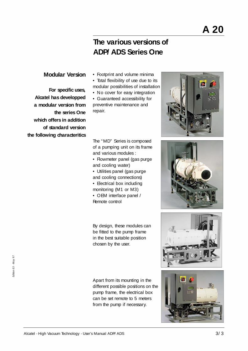
• Footprint and volume minima• Total flexibility of use due to itsmodular possibilities of installation• No cover for easy integration• Guaranteed accessibility forpreventive maintenance andrepair.
The “MD” Series is composedof a pumping unit on its frameand various modules :• Flowmeter panel (gas purgeand cooling water)• Utilities panel (gas purgeand cooling connections)• Electrical box includingmonitoring (M1 or M3)• OEM interface panel /Remote control
By design, these modules canbe fitted to the pump framein the best suitable positionchosen by the user.
Apart from its mounting in thedifferent possible positions on thepump frame, the electrical boxcan be set remote to 5 metersfrom the pump if necessary.
Modular Version
For specific uses,Alcatel has developpeda modular version from
the series Onewhich offers in addition
of standard versionthe following characteritics

Alcatel - High Vacuum Technology - User’s Manual ADP/ADS
Editi
on 0
4 - M
ay 9
8
A 30ADP/ADS Series One dry pumpsfor semi-conductor’s industry
1/3
Clean processes
The ADP / ADS range is designed for three typesof applications :
This concerns all applications for clean pumping (particle-free)and non-corrosive gases (load lock pumping for example).No nitrogen purge needed.
ADP 31/ADP 81ADS 151/301/501
equipment
Water
Anti-suckback valve
Silencer
11
12
10
Inlet
Motor
Motor
Exhaust
13
10 - Water electrovalve 12 - Water flow sensor11 - Water flowmeter 13 - Isolation valve
(accessory)

Alcatel - High Vacuum Technology - User’s Manual ADP/ADS
Editi
on 0
4 - M
ay 9
8
A 30ADP/ADS Series One dry pumpsfor semi-conductor’s industry
2/3
Corrosive processes This concerns all applications for pumping chlorinated,fluorinated, crystallizable or condensable gases, (for example : ion implantation, etching, epitaxy...). This version contains a nitrogen injection system in all the pump’s stages.
It is used to help evacuate pollutants produced by the process,dilute the harmful gases present in the compression stages andprotect the mechanical parts of the pump.
Gas injection at the different stages of the pump :
The neutral gas (usually nitrogen) injection system is usedto decrease the concentration of process gases and thecondensation of gases in the pump.
The nitrogen injectionsystem
ADP 31/ADP 81ADS 151/301/501
equipment
Water
Neutral gas
Anti-suckback valve
Silencer
6
9
5
10
4 3 2 1
7 8
12
11
Inlet
Exhaust
13
1 - LP1 2 - LP2 3 - LP3 4 - HP4 5 - HP5 : Gas injection (calibrated jets with valves)6 - Gas electrovalve 7 - Gas flowmeter8 - N2 flow sensor (optional) 9 - Pressure regulatorCooling system:10 - Water electrovalve 11 - Water flowmeter12 - Water flow sensorAccessories:13 - Isolation valve

Alcatel - High Vacuum Technology - User’s Manual ADP/ADS
Editi
on 0
4 - M
ay 9
8
A 30ADP/ADS Series One dry pumpsfor semi-conductor’s industry
Very corrosives processes“TC“ CVD type
3/3
Several models are available for the CVD processes which aregenerating lots of quantities of particles and condensable gases(BPSG, TEOS, LPCVD nitride…). Compared to the previousversion, the main differences are the following:
- nitrogen injection and cooling circuit are optimized to avoiddeposition and condensation.- ADP temperature controlled device.- extra protections of ball bearings against process particulatesare used in ADP and Roots.
ADP 81/ ADS 151/301/501/801/1001
equipment
N2 flow sensor(optional)
6
9
510 4 3 2 1
7 8
10
11
12
Inlet
Water
Neutral gas
Exhaust
Anti-suckback valve
Silencer
1 - LP1 2 - LP2 3 - LP3 4 - HP4 5 - HP5 : Neutral gas injection
6 - Shut-off valve 7 - Gas flowmeter8 - N2 flow sensor (option) 9 - Pressure regulator
Cooling system:10 - Water electrovalve 11 - Water flowmeter
Accessories:12 - Isolation valve
This sensor (8) is used to warn the user when the N2 flow comesunder a preset value during harsch processes(SiH4 for example).
Note : The ”TC” version (Temperature Controlled) includes anoptimized cooling circuit and a temperature regulation on theADP. These functions can be installed on equipment for corrosiveprocesses without CVD option.

Alcatel - High Vacuum Technology - User’s Manual ADP/ADS
Editi
on 0
4 - M
ay 9
8
M1 Solid-state monitoring without neutral gas control, M3 monitoring driven by a microprocessor .
Parameters monitored :• Water flow failure• Electrical overloadingMonitoring system M1 canbe remote controlled.
This is a unit separatedfrom the frame (5 or10 meters cable) for theremote control andmonitoring of the pump.
A 40Types of monitoring systems
1/1
2 types of monitoringsystem
Monitoring system M1
M1 Remote monitoringsystem
5 or 10 meters
Monitoring system M3 • Monitoring system controlledby microprocessor• LCD display of parametersand messages• Memorization of the 10latest alerts and alarms• RS 232 - RS 485 -NETWORK links
This monitoring system can directly be interfaced with most of the production equipments.Parameters monitored :• Water flow failure• Purge flow failure• Electrical overloading• Purge flow and exhaust pressure• Exhaust gas temperature • ADP motor power• Water flow rate• Maintenance Time

Alcatel - High Vacuum Technology - User’s Manual ADP/ADS
Editi
on 0
3 - M
ay 9
7
A 50Dry pumpoperational principle
Multi-stage Rootsprinciple
1/3
The ADP pump consists of 5 Roots type stages.The two rotors rotate without touching each other.
Water
Inlet
Stage 1(LP1)
Stage 2(LP2)
Stage 3(LP3)
Stage 4(HP4)
Stage 5(HP5)
Silencer
The three stages on the low pressure side are called “LP stages”and the two stages on the high pressure side are called“HP stages”.
Exhaust

Alcatel - High Vacuum Technology - User’s Manual ADP/ADS
Editi
on 0
3 - M
ay 9
7
A 50Dry pumpoperational principle
Tightnesswith environment
Tightness at lowpressure side
Tightness at highpressure side
2/3
The pump bearings on the low pressure side are fitted withceramic ball bearings lubricated with fluorinated grease whichresists high temperatures and the possible corrosion due tothe application. An overpressure zone is created around the bearing byinjecting a neutral gas (Purge LP1). The grease works in aless severe vacuum and thus lasts longer. This pressurization also prevents pumped gases from migratingtowards the bearings.
Neutral gas purging for the bearings is imperative for corrosiveprocesses.
The bearings are lubricated byoil splashing. The oil sump is sealed fromstage HP5 by a trap and adeflector.
This trap is also used :- as a heat barrier - as a pumped gas barrier- to recover fluid 1 - Stage HP5
2 - Trap3 - Water cooling4 - HP5 purge5 - Dynamic seal6 - Lubrication disk7 - Gear casing
1
3
2
5
76
4

Alcatel - High Vacuum Technology - User’s Manual ADP/ADS
Editi
on 0
3 - M
ay 9
7
A 50Dry pumpoperational principle
3/3
The pump in a pumpinginstallation
Tightness at motor side(shaft passage)
Tightness at shutdown
The vacuum tightness isensured by the motor designwith built-in jacket.
This system provides totalsafety regarding leaksoutside the pump andrequires no maintenance.
1 - Built-in jacket2 - Motor housing3 - Electrical rotor
1
2
3
The pump is fitted with a antisuckback valve in the silencer,preventing the exhaust being sucked back.
Processchamber
INLETPRESSURE
ATMOSPHERICPRESSURE
Secondarypumping
ADPpump
SECO
ND
ARY
VA
CUU
MPR
IMA
RYV
ACU
UM
ATM
OSP
HER
E

Alcatel - High Vacuum Technology - User’s Manual ADP/ADS
Editi
on 0
4 -
Janu
ary
98
A 60The accessories
Isolation valveat pump inlet
Anti-vibration pads
1/1
Principle : This valve avoids a reverse flow of particles tothe chamber and increases tightness when thepump is switched off. It allows also to isolatethe running pump from the process.
Part Number : Several models are available in Alcatel catalog(Manual valve, electropneumatic...).Consult us.
Fitting : See section B 90
Principle : This device significantly reduces the vibration ratetransmitted to the floor.Vibration force to the floor by pad: < 0,5N -Available till 150Hz.
Part Number : ADP . . . . . . . . . . . . . .101838ADP MD . . . . . . . . . . .101942ADS 151/301/501 . . .101840ADS 151/301/501 MD 101941ADS 801/1001 . . . . . .102136
Fitting : See section B 30
Principle : This device is to be installed on the silencer in orderto avoid the gases condensation, particularly inprocesses such as Aluminum etching, Polysiliconetching, LPCVD or PECVD Nitrid.
Part Number : 110/115 V . . . . . . . . .105038220/240 V . . . . . . . . .105037
Fitting : See section B 170
Silencer heating kit
Alcatel - High Vacuum Technology - User’s Manual ADP/ADS
Editi
on 0
4 - M
ay 9
8
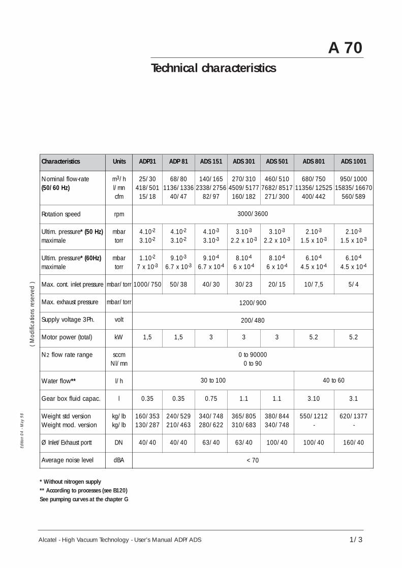
A 70Technical characteristics
1/3
* Without nitrogen supply** According to processes (see B120)See pumping curves at the chapter G
ADS 1001
950/100015835/16670
560/589
2.10-3
1.5 x 10⁻³
6.10-4
4.5 x 10⁻⁴
5/4
5.2
3.1
620/1377-
160/40
ADP31
25/30418/50115/18
4.10-2
3.10-2
1.10-2
7 x 10⁻³
1000/750
1,5
0.35
160/353130/287
40/40
3000/3600
1200/900
200/480
0 to 900000 to 90
< 70
30 to 100 40 to 60
ADS 801
680/75011356/12525
400/442
2.10-3
1.5 x 10⁻³
6.10-4
4.5 x 10⁻⁴
10/7,5
5.2
3.10
550/1212-
100/40
ADS 501
460/5107682/8517
271/300
3.10-3
2.2 x 10⁻³
8.10-4
6 x 10⁻⁴
20/15
3
1.1
380/844340/748
100/40
ADS 301
270/3104509/5177160/182
3.10-3
2.2 x 10⁻³
8.10-4
6 x 10⁻⁴
30/23
3
1.1
365/805310/683
63/40
ADS 151
140/1652338/2756
82/97
4.10-3
3.10-3
9.10-4
6.7 x 10⁻⁴
40/30
3
0.75
340/748280/622
63/40
ADP 81
68/801136/1336
40/47
4.10-2
3.10-2
9.10-3
6.7 x 10⁻³
50/38
1,5
0.35
240/529210/463
40/40
Units
m3/hl/mncfm
rpm
mbartorr
mbartorr
mbar/torr
mbar/torr
volt
kW
sccmNl/mn
l/h
l
kg/lbkg/lb
DN
dBA
Characteristics
Nominal flow-rate(50/60 Hz)
Rotation speed
Ultim. pressure* (50 Hz)maximale
Ultim. pressure* (60Hz)maximale
Max. cont. inlet pressure
Max. exhaust pressure
Supply voltage 3Ph.
Motor power (total)
N2 flow rate range
Water flow**
Gear box fluid capac.
Weight std versionWeight mod. version
Ø Inlet/Exhaust portt
Average noise level
( Mod
ifica
tions
rese
rved
)

Alcatel - High Vacuum Technology - User’s Manual ADP/ADS
Editi
on 0
4 - M
ay 9
8
A 70Technical characteristics
2/3
DimensionsStandard version
B
F H
E
A
G
95
REFOULEMENT
ASPIRATION
DI
C
J
Inlet
Exhaust
DIMENSIONS IN MILLIMETERSPUMP
A B C D E F G H I J
ADP 31 1027 975 340 170 680 650 350 711 250 884ADP 81 1177 1125 340 170 680 650 375 711 250 1034ADS 151 1177 1125 398 199 875 830 520 909 278 1040ADS 301 1177 1125 398 199 875 830 520 909 278 1040ADS 501 1177 1125 398 199 875 830 520 909 278 1040ADS 801 1368 1331 398 199 960 913 650 995 278 1230ADS 1001 1510 1445 398 199 1050 945 720 1050 278 1360
DIMENSIONS IN INCHESPUMP
A B C D E F G H I J
ADP 31 40.4 38.4 13.4 6.7 26.8 25.6 13.8 28.0 9.8 22.5ADP 81 46.3 44.3 13.4 6.7 26.8 25.6 14.8 28.0 9.8 26.0ADS 151 46.3 44.3 15.7 7.8 34.4 32.7 20.5 35.8 10.9 26.0ADS 301 46.3 44.3 15.7 7.8 34.4 32.7 20.5 35.8 10.9 26.0ADS 501 46.3 44.3 15.7 7.8 34.4 32.7 20.5 35.8 10.9 26.0ADS 801 53.8 52.4 15.7 7.8 37.8 35.9 25.6 39.2 10.9 31.2ADS 1001 59.4 56.8 15.7 7.8 41.3 37.2 28.3 41.3 10.9 34.5

Alcatel - High Vacuum Technology - User’s Manual ADP/ADS
Editi
on 0
4 - M
ay 9
8
A 70Technical characteristics
3/3
DimensionsModular version
H I 15
45
GF
ED
C
J
BA
200
EXHAUST
INLETINLET
DIMENSIONS IN MILLIMETERSPUMP
A B C D E F G H I J
ADP 31MD 557 - 290 160 320 710 400 135 730 223ADP 81MD 557 - 290 160 320 710 400 135 840 223ADS 151MD 733 794 290 160 320 710 400 135 840 223ADS 301MD 805 861 290 160 320 710 400 135 840 223ADS 501MD 805 861 290 160 320 710 400 135 840 223
DIMENSIONS IN INCHESPUMP
A B C D E F G H I J
ADP 31MD 21.9 - 11.4 6.3 12.6 27.9 15.7 5.3 28.7 8.8ADP 81MD 21.9 - 11.4 6.3 12.6 27.9 15.7 5.3 33.1 8.8ADS 151MD 28.8 31.2 11.4 6.3 12.6 27.9 15.7 5.3 33.1 8.8ADS 301MD 31.7 33.9 11.4 6.3 12.6 27.9 15.7 5.3 33.1 8.8ADS 501MD 31.7 33.9 11.4 6.3 12.6 27.9 15.7 5.3 33.1 8.8

B 00
Alcatel - High Vacuum Technology - User’s Manual ADP/ADS
Safety instructions
1/2
Editi
on 0
3 - M
ay 9
7
• The machines must be connected to an electrical installation incompliance with the decree 88-1056 dated 14 Novembre 1988.
• Our products are designed to comply with current EECregulations. Any modification of the product made by the user isliable to lead non-compliance with the regulations, or even to putinto doubt the EMC (ElectroMagnetic Compatibility) performanceand the safety of the product. ALCATEL declines anyresponsability for such operations.
• Before any maintenance operation is perfomed by amaintenance technician who has not received safety training(EMC, electrical safety, chemical pollution, etc.), isolate theproduct from the various energy sources (electricity, compressedair, etc.).
• The EMC perfomance of the product is obtained on thecondition that the installation complies with the EMC rules. In particular, in disturbed environments, it is essential to:
- use shielded cables and connections for interfaces,- stabilize the power supply line with meshing from the
power supply source to a distance of 3m from the product inlet.
• When the main switch is set to “0“, a part of the equipmentremains energized. Live circuits are exposed and accidentalcontact is possible (Energized electrical Work “Hot Work“ incompliance with SEMI S2-93 Type 4). Before any maintenanceoperation, disconnect the main electrical cable.
Risk of electrical shock Switch off the pump anddisconnect the main cable.Do not operate inside if yourare not trained andauthorized

B 00
Alcatel - High Vacuum Technology - User’s Manual ADP/ADS
Safety instructions
2/2
Editi
on 0
3 - M
ay 9
7
• The EMO device is a pump EMO, not a system EMO, so it shutsonly this part of the equipment. To allow the pump to start, turn theEMO button clockwise and pull it. To control the system EMO, it isnecessary to wire the corresponding contacts on the "Emergency" plug(see B 140). Either, you can stop the pump from the system EMO bywiring the terminals on "Remote" connector (see B 140).
• Units containing control circuits are designed to guarantee normalsafety conditions taking into account their usual operating environment(use in cabinet). In specific cases of use on a table, take care not toinsert objects in the ventilation louvers when handling units.
• When switching off an item of equipment containing capacitorsloaded with over 60VDC or 25 VAC, take precautions at the access tothe connector pins (single-phase motors, fitting with mains filter,frequency converter, monitoring system, etc.).
• The machines are designed so as to prevent any thermal risk to theuser's safety. However, specific operating conditions may generate onthe pump, temperatures justifying particular attention on the part of theuser (external surfaces > 70°C). Hot surfaces which can cause seriousburns when touched are signalled with specific label.
• Alcatel has no control over the types of gases passing through thispump. These are entirely under the control of the process user and/orthe hardware systems integrator. Frequently, process gases are toxic,flammable, corrosive, explosive an otherwise reactive. Since thesegases can cause serious injury or death, it is very important to plumbthe exhaust of the pump to the facility's hazardous gas exhaust systemwhich incorporates appropriate filters, scrubbers, etc., to insure thatthe exhaust meets all air and water pollution control regulations.
• The enclosures have to be exhausted with a volumetric flow rate of86 CFM, with a duct static pressure of 0.35” w.g. (as measured 2.0’from the duct connection to the cabinet). The size of the exhaust ductis 4”, the material can be PVC, except for flammable gases for wichstainless steel is strongly advised.
Hot surface Hot surface near the label(pump body, silencer...)

mm ± 50 (inch ± 2)ADP 31/81 SD and MDADS 151/301/601 St and MDADS 801/1001
A1350 (53)
1350 (53)
1900 (74.6)
B500 (38)
1150 (45)
1520 (58)
C980 (19.7)
520 (20.1)
810 (32)
B 10
Alcatel - High Vacuum Technology - User’s Manual ADP/ADS
Unpacking / Storage
1/2
Editi
on 0
3 - M
ay 9
7
Outer crate
Inner crate
Pump(Standard)
Palett
B
A
C
If the equipment has been damaged, take necessarysteps with the carrier and inform Alcatel, if necessary.
In all cases, Alcatel recommends that the packaging be saved,in the event that the equipment must be transported or put intoprolonged storage.
Risk of tilting: Even when compliance with EEC safetyrules is guaranted (normal range ± 10°), it is
recommended to take precautions as regards the risk of tiltingduring product handling, installation and operation.
• Remove the top of the outer crate.
• Remove the long side of the outer crate. This side is attachedwith screws; all the other sides are held with nails.
Unpacking

90° maxi
Pump Type Weight in Ibs/(kg)
ADP 31 353 (160)ADP 81 529 (240)
ADS 151 748 (340)ADS 301 805 (365)ADS 501 844 (380)ADS 801 1212 (550)
ADS 1001 1377 (620)
B 10
Alcatel - High Vacuum Technology - User’s Manual ADP/ADS
Unpacking / Storage
2/2
Editi
on 0
3 - M
ay 9
7
Remove the pumpfrom the crate
Prepare the pump
Equipment storage
It is highly recommended toused a hoist. Lift the pumpby its three hoisting rings.Apply just enough upwardtension to take the weightoff the base of the pump.
Screw the leveling pads of the frame and lower the pumpon the wheels.Remove any additional packages from the crate and set aside.These packages will contain cables, accessories, and so forth.
To prevent humidity from entering the pump during transport,the pump is pressurized with dry nitrogen before shipment.The inlet and exhaust are sealed with blank-off flanges whichshould not be removed until the pump is ready to be used.
Hook
Hoistingring
For all equipment handling, use the devices providedfor this purpose (lifting rings, handle, etc.) .
If the pump is going to be put into storage, the inlet andexhaust, seals should be left in place.
Our equipment can be stored without particular storage precautions (pump pressurized in nitrogen and sealed) at anambient temperature between -20°C and + 70°C.

B 20
Alcatel - High Vacuum Technology - User’s Manual ADP/ADS
Positioning the pumpin the pumping installation
1/3
Editi
on 0
3 - M
ay 9
7
Positioning the pump
• Pump performance will depend on the kinds ofaccessories used and the quality of the mechanicalconnections such as pump fittings.
• As these pumps are typically used in a corrosiveatmosphere, their reliability will depend on proper installationand maintenance. When assembling the vacuum circuit, makesure to provide necessary maintenance accessories such asshut-off valves on the inlet, exhaust, and purge lines.
• For safety reasons, use accessories on the inletand exhaust lines whose materials and sealing propertiesare compatible with the gases being used.
The pump must be operated in the horizontal position,with the pumping axis vertical and the inlet openingupwards.
Determine where the pump will be placed. Refer to the technicalspecifications section for dimensions, if needed (section A).
Use a hoist to handle the pump, lifting it by the three hoistingrings.
Each pump is equipped witha locking screw jack on each corner.Lock the pump by adjusting these jacks so that all four feetare resting solidly on the floor.
See section B30 for installingAnti-vibration Pads.

B 20
Alcatel - High Vacuum Technology - User’s Manual ADP/ADS
Positioning the pumpin the pumping installation
Remove pump covers
2/3
Editi
on 0
3 - M
ay 9
7
• Unfasten the toggle joints located on the top of the cover (1).
• Unfasten the lateral fastening and raise the cover bythe handles (2).
2
2
1
1
Toggle joints
Lateral fastening
Side cover
Handle

Alcatel - High Vacuum Technology - User’s Manual ADP/ADS
Editi
on 0
3 - M
ay 9
7
Removingthe shipping braces
Modular version
B 20Positioning the pumpin the pumping installation
3/3
Release the pump(s) from the frame before use.Keep the flanging components in order to dispatch the equipment, if required.
Failure to remove the shipping braces could later causethe pump to seize as a result of a strain exertedby the braces.
• The shipping braces hold the pump to the frame duringshipment. They are painted yellow, for easy identification.
• Remove these bars and the threaded rods which hold them.
The shipping braces are alsoused as hoisting device.
Risk of tilting: Even when compliance with the EECsafety rules is guaranteed (normal range ± 10°), it is
recommended to take precautions as regards of the risk oftilting during product handling, installation and operation.
Securing nutTransversal bar
Screw
Securing nutTransversal barThreaded rod

B 30
Alcatel - High Vacuum Technology - User’s Manual ADP/ADS 1/1
Editi
on 0
3 - M
ay 9
7
Installing anti-vibration pads(Accessories)
The ADP/ADS pumps can be equipped with anti-vibration padswhich are mounted beneath the pump, near the locking feet.
• Remove the covers as described in section B 20.
• Raise the pump using the 4 screws jacks.
• Screw into the previous holes the 4 anti-vibration pads.
• Screw the screw jacks so that the machine rests on the pads.
Force transmitted to the ground by each support: < 0.5 N for frequencies ≤ 150 Hz.
In order to limit the transmission of vibrations along the pipes, itis recommended to use «flexible» connection accessories at theinlet and exhaust side (expanding type).
On the modular version :
• Screw the delivered angleinto the frame holes afterremoving the shippingbraces.
•Install the anti-vibration pads(as shown opposite).
Anti-vibration pads
ADP/ADSStandard version
ADP/ADSModular version

B 40
Alcatel - High Vacuum Technology - User’s Manual ADP/ADS
Modular version - Layout
1/2
Editi
on 0
3 - M
ay 9
7
Stabilizer kitfor modular ADS
Positioning in pumpinginstallation
Main modules layout(electrical box, flowmeterpanel, water and gas utilities,customer interface) fit thecustomer choice among factoryset configurations.Other layouts are possible,see the following page.
To modify the modules layout, some rules have to be followed :- Pump(s) cannot change its(their) orientation with respect tothe frame.- The sensor box, located under the pump, has to be set facingthe silencer.
For safety reasons, the modular ADS are now equipped with astabilizer to avoid any risk oftoppling over. It consists of twosupports, one either side of theframe, equipped with rollers atthe bottom.They slide into ahousing and are bolted into placeduring transport. The housing isbolted to one end of the frame.
When pump is installed, thesupports are stored, legs up, andfixed by means of two bolts.This kit is a part of modularpumps marked with a serialnumber upper than 973187. It can be fitted to retrofit on olderpumps by ordering P/N 104527.
See page B 20.
Sensor box

B 40
Alcatel - High Vacuum Technology - User’s Manual ADP/ADS
Modular version - Layout
5 basics modules for8 pumps configurations
2/2
Editi
on 0
3 - M
ay 9
7
Some location examples
Exhaust Exhaust
A
Inlet
B
Inlet
C
Inlet
D
Inlet
E
Inlet
F
Inlet
G
Inlet
H
Inlet
Pump block with frame
Control box with integrated monitor
Flowmeter panel
OEM interface Utilities panel
CONTROLBOX
CONTROLBOX
EXHAUST
CONFIGURATION A CONFIGURATION F
INLET
MOTOR
MOTOR
WATER & N2SUPPLIES
WATER & N2SUPPLIESPOWER SUPPLY POWER SUPPLY
FLOWMETERPANEL
EXHAUST

B 50
Alcatel - High Vacuum Technology - User’s Manual ADP/ADS
Filling the machine oil housings
1/2
Editi
on 0
4 - M
ay 9
8
Caution ! The pumps are delivered without an oil charge:the oil is found in separate containers. Similarly, it is
recommended to drain the pump before redispatching theequipment.
For machines wich use lubricants, it is recommended torequest the manufacturer for the safety data sheets
concerning the product used.
The pump is tested using synthetic fluid Alcatel 113.
When pumping corrosive gases, we recommend synthetic fluidAlcatel 113.
Mineral and synthetic oils cannot be used together.Contact Alcatel or your service agent before making
any changes.
Oil quantities OIL FILLING :
HOUSINGS :REAR FRONT TOTAL
ADP ROOTS ROOTS CAPACITYHOUSING HOUSING
ADP 31/81 0.35 L 0.35 LADS 151 “ 0.25 L 0.15 L 0.75 LADS 301 “ 0.45 L 0.25 L 1.05 LADS 501 “ 0.45 L 0.25 L 1.05 LADS 801 " 1.95 L 0.80 L 3.10 LADS 1001 " 1.95 L 0.80 L 3.10 L
Filling procedure - Proceed to oil filling when the pump is stopped.- Remove the fill cap.- Fill the pump with oil.Do not exceed the indicated quantities.
The oil level should be in the middle of the sight glass.For this to be accurate, wait a few minutes for the oil to settle over all internal surfaces.
Replace the fill cap.(See location page 2)

B 50
Alcatel - High Vacuum Technology - User’s Manual ADP/ADS
Filling the machine oil housings
2/2
Editi
on 0
4 - M
ay 9
8
Location
1 - Filling front Roots housing2 - Front Roots housing level
sight glass3 - ADP filling4 - ADP housing oil level sight
glass5 - Rear Roots housing filling6 - Roots housing oil level sight
glass
1
2
3
6
5
4

B 60
Alcatel - High Vacuum Technology - User’s Manual ADP/ADS
Connection to the cooling circuit
1/2
Editi
on 0
3 - M
ay 9
7
Water characteristics
Standard versionconnections
In order to limit corrosion and fouling of the motor cooling coils,it is recommended to use cooling water with the followingcharacteristics :
Treated fresh water or non-aggressive industrial water pH between 7.5 and 11 Hardness < 7 milli-equivalent/dm3 Resistivity > 1500 Ω.cm Solid pollution < 100 mg/dm3 Temp. from 10° to 25°C Pressure range between 3 and 7 bars absolutes Pressure ∆ inlet/outlet 3 bars mimimum
If the above mentioned characteristics are not respected, installa filter to the cooling connection.
OUTIN
REARVIEW 1/4 NPT 1/4 Gas
1/4 Gas1/4 NPT
ALCATEL supply

B 60
Alcatel - High Vacuum Technology - User’s Manual ADP/ADS
Connection to the cooling circuit
Modular versionconnections
2/2
Editi
on 0
3 - M
ay 9
7
Waterflowrateadjustment
OUT
N2
IN
OUT
N2
IN WaterIN/OUT
REARVIEW
The water flow will be adjusted according to the processes withthe needle tap (see section B120).
PRESSUREN2 FLOWWATERFLOW
Flowmeter panel Needle tap
Waterflowrate

B 70
Alcatel - High Vacuum Technology - User’s Manual ADP/ADS
Inert gas purge connection(N2 plug)
1/2
Editi
on 0
4 - M
ay 9
8
Nitrogen characteristics
Standard versionconnections
A filtered dry nitrogen supply is required. It should have the following characteristics :
Dew point < 22° C Dust < 1µ.m Oil < 0,1 PPM Pressure between 3 and 7 bar absolute. Flowrate per pump: 100 l/min.
Modular versionconnections
OUT
N2
IN
OUT
N2
IN
OUTIN
1/8 Gas
REARFACE
Customer supply
Gas
4 m
m6
mm
1/8 Gas
ALCATEL supply
REARFACE

B 70
Alcatel - High Vacuum Technology - User’s Manual ADP/ADS
Inert gas purge connection(N2 plug)
2/2
Editi
on 0
4 - M
ay 9
8
N2 flowrateadjustment
The N2 flowrate will be adjusted with the pressure regulatoraccording to the process (see section B 120).
The flowmeter is used to display the overall purge flow rate.
PRESSUREN2 FLOWWATERFLOW
Flowmeter panel
Pressuregauge
Purge gasflowmeter
Pressureregulator

B 80
Alcatel - High Vacuum Technology - User’s Manual ADP/ADS
Nitrogen purge flow sensor
Function
1/1
Editi
on 0
3 - M
ay 9
7
Operation
Location
Adjustment
This sensor is used to warn the user when the N2 flow comesunder a preset value during harsch processes using dangerousgases (SiH4 for example).
The gas flow rate through the detector carries along a floatwhich acts on the contact of the electrical box.This contact closes when the flow rate value is higher than the flow rate set on the sensor. Otherwise the contact opens and set offan alarm “PURGE FLOW“.
To get access to the flowmeter, remove the side cover fromthe pump.
- First set the parameter"N2 FLOWRATE OPTION" to be valid in the "DEFINITION menuof the M3 monitoring system.- The setting of the sensor isdone by sliding the moving part(contact) along the controller body.For this, loosen the screws fixingthis moving part on the body- Adjust the electrical box in theupper position.- Set the minimum Nitrogenflowrate to be detected with the correspondingpurge pressure (See B 120).- Adjust the position of the moving part from top to bottom untilthe PURGE FLOW is displayed on the screen of M3 monitoring.Fix it with the screws.- Check the good operation by increasing the purge pressure toa level higher than the one to be detected, then reduce thispressure until the purge alert is triggered. Note if this triggeringpressure corresponds to the minimum required one.
0.3
Nl/mnN2
N2 outlet
N2 inlet
Electrical box
Alcatel - High Vacuum Technology - User’s Manual ADP/ADS
Editi
on 0
3 - M
ay 9
7
B 90Connection to the pumping circuit
1/2
In order to prevent moisture from entering the pumpbefore its installation, it is pressurized beforehand with
nitrogen and sealed with blank-off flanges.
The vacuum pump is also a compressor: incorrect use may be dangerous. Study the user manual before
commissioning the pump
First of all, remove the plug at the exhaust.
For safety reasons, use at pump inlet as well as exhaust,accessories with materials and tightness compatible with pumpedgases.
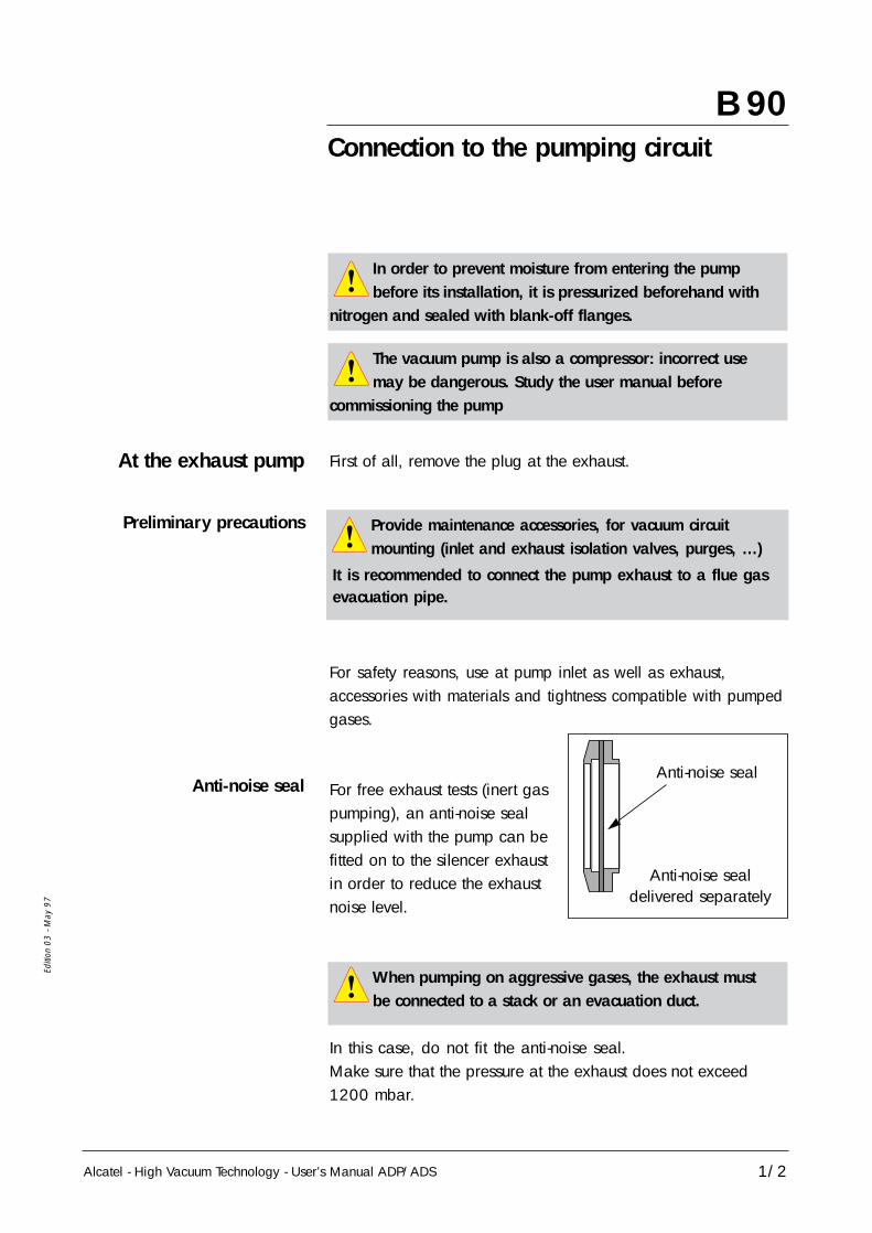
For free exhaust tests (inert gaspumping), an anti-noise sealsupplied with the pump can befitted on to the silencer exhaustin order to reduce the exhaustnoise level.
In this case, do not fit the anti-noise seal.Make sure that the pressure at the exhaust does not exceed1200 mbar.
Anti-noise seal
Anti-noise sealdelivered separately
At the exhaust pump
Anti-noise seal
Preliminary precautions
When pumping on aggressive gases, the exhaust mustbe connected to a stack or an evacuation duct.
Provide maintenance accessories, for vacuum circuitmounting (inlet and exhaust isolation valves, purges, …)
It is recommended to connect the pump exhaust to a flue gasevacuation pipe.

Alcatel - High Vacuum Technology - User’s Manual ADP/ADS
Editi
on 0
3 - M
ay 9
7
B 90Connection to the pumping circuit
2/2
Exhaust connection DN40 ISO KF Pneurop.Several fitting accessories are available in Alcatel catalog.
At inlet pump
Inlet isolation valve(accessory)
In order to prevent foreign bodies from entering the pump,leave the blank-off flange in place at the pump inlet and removeit at the time of use.(see section B 130).
This accessory avoids a reverse flow of particles tothe chamber when the pump is stopped.Connect the valve directly on the pump inlet flange usingconnecting accessories.Connect the valve to the chamber.Connect the electrical cable to the "inlet valve / exhaust valve"connector at the rear of the M3 monitoring system.
Make sure that the parts or containments connected tothe inlet of our pumps withstand a negative pressure of
1 bar with reference to the atmospheric pressure.

B 110
Alcatel - High Vacuum Technology - User’s Manual ADP/ADS
Pump Power supply
1/3
Editi
on 0
4 - M
ay 9
8
Customer electricalinstallation protection
All the electrical connections required for operation have beendone in the factory.However, the user must make the electrical connection ofthe main power supply, connect the remote monitoring systemoptions.
For any change of power supply voltage in relation to the initialconfiguration, contact Alcatel Customer Service.
Cutt off rating of main pump switch :- 200 to 415 V : 50 kA- 460 V : 20 kA- 480 V : 10 kA
The main switch on themonitoring front panel can be locked with a catch hookattached to the emergency stopbutton. Even if the main switch is locked in the "1" position, the disconnecting functionremains operational.
MAIN CIRCUIT BREAKER RATING : (Minimum value) :
ADP 31/81 ADP 81V ADS 151/301/501 ADS 801/1001
LV 15A 20A 20A 25A
HV 10A 15A 15A 20A
Study the preliminary precautions (See B 00)

Modular version
B 110
Alcatel - High Vacuum Technology - User’s Manual ADP/ADS
Pump Power supply
2/3
Editi
on 0
4 - M
ay 9
8Mains connector is locatedon the electrical box lowerface.The connection has to becarried out as definedpreviously in page 1.
Mains connector
Standard version The pump is supplied with a female connector which isconnected to the electrical connector at the lower part of theframe. Connect the mains to the power supply connector usinga 4 x 4 mm2.Then connect the connector on the pump frame.
Groundphase 3phase 2phase 1
Y/G
Female connector(6 pins + Ground) Rear of pump
Check the rotational direction of the pump at the firstpump start-up (See section B 130).

B 110
Alcatel - High Vacuum Technology - User’s Manual ADP/ADS
Pump Power supply
3/3
Editi
on 0
4 - M
ay 9
8
Connectors of remoteset electrical box
Remote set electrical box isconnected by means of a 5 meters extension cable.
1
7
68
32
4
5
Check the rotational direction of the pump at the firststart-up (See B 130).
1 Mains connector 2 Roots supply (ADS)
3 Remote control 4 Sensors information (n° 1)
5 RS 232 / RS 485 6 Interface connector
7 ADP supply 8 Sensors information (n° 2)

Alcatel - High Vacuum Technology - User’s Manual ADP/ADS 1/2
Editi
on 0
4 - M
ay 9
8
B 120Water flowrate and gas purge accordingto main semiconductor processes
Standard pump setting (no TC)
Processes Pump version Nitrogen Water
• Load lock non CVD No 100l/h* If possible chlorine degassing *20l/mn (0.2 bar)• Sputtering non CVD No 100l/h• Dielectric etch non CVD 25l/mn (0.3 bar) 60l/h• Stripping with plasma O2 - non CVD 25l/mn (0.3 bar) 60l/h
trap can be useful(proposed by some manufacturers)
• Resist and polyamid etch - non CVD 25l/mn (0.3 bar) 60l/htrap can be useful(proposed by some manufacturers)
• Metal etch - heated piping and non CVD 35l/mn (0.6 bar) 40l/hexhaust lines advised
• Poly etch non CVD 35l/mn (0.6 bar) 60l/h• Ion implant (source) non CVD 35l/mn (0.6 bar) 40l/h• Tungsten LPCVD non CVD 45l/mn (1 bar) 100l/h• Titanium and Titanium nitride PECVD non CVD 35l/mn (0.6 bar) 60l/h• Polysilicon LPCVD and PECVD CVD 50l/mn (1 bar) 60l/h• Silicon oxide PECVD and LPCVD CVD 50l/mn (1 bar) 60l/h
using Silane
• Silicon oxide and doped oxide CVD 50l/mn (1 bar) 60l/h(BPSG) PECVD using TEOS
• Silicon oxide and doped oxide CVD 70l/mn (1.5 bar) 40l/h(BPSG) LPCVD using TEOS
• Silicon nitride PECVD CVD 70l/mn (1.5 bar) 40l/h• Silicon nitride LPCVD - CVD 90l/mn (2 bar) 40l/h
cold trap at the oulet of the furnacecan be useful - no heating of the linebetween the cold trap and the pump.
* Should the layer be thick (>1500A),please contact Alcatel WorldwideTechnical Support for dry pumps.
PRO
CESS
ES 1
PRO
CESS
ES 3
P 1
Mai
nten
ance
P 2
Mai
nten
ance
P 3
Mai
nten
ance
PRO
CESS
ES 2

B 120
Alcatel - High Vacuum Technology - User’s Manual ADP/ADS
Water flowrate and gas purge accordingto main semiconductor processes
2/2
Editi
on 0
4 - M
ay 9
8
Processes Pump version Nitrogen Pumptemperature
• Metal etch - heated piping and non CVD 35l/mn (0.6 bar) 90°Cexhaust lines advised
• Poly etch non CVD 35l/mn (0.6 bar) 80°C• Polysilicon LPCVD and PECVD CVD 45l/mn (0.8 bar) 80°C• Silicon oxide PECVD and LPCVD CVD 50l/mn (1 bar) 80°C
using Silane• Si mono. Epitaxy CVD 50l/mn (1 bar) 80°C
• Silicon oxide and doped oxide CVD 50l/mn (1 bar) 90°C(BPSG) PECVD using TEOS
• Silicon oxide and doped oxide CVD 70l/mn (1.5 bar) 90°C(BPSG) LPCVD using TEOS
• Silicon nitride PECVD CVD 70l/mn (1.5 bar) 90°C• Silicon nitride LPCVD - CVD 90l/mn (2 bar) 100°C
cold trap at the oulet of the furnacecan be useful - no heating of the linebetween the cold trap and the pump.
* Should the layer be thick (>1500A),please contact Alcatel WorldwideTechnical Support for dry pumps.
PRO
CESS
ES 3
PRO
CESS
ES 2
“TC“ Pump setting

B 130
Alcatel - High Vacuum Technology - User’s Manual ADP/ADS
Checking the rotational direction
1/1
Editi
on 0
3 - M
ay 9
7
Before using the pump, check that the connectionsdefined in the start-up chapter have been made.
Also, make sure that all the oil levels are visible at the centerof the indicator.
• Remove the guards blocking the intake and exhaust(and, if applicable, purge) holes; these components preventsforeign bodies from entering the pump during transport andstorage. It is dangerous to leave them on a pump in operation.
• Remove the blank-off flange on the inlet port. • Fit a pressure gauge at the pump inlet.• Set the main switch on I.
• Start up the pump by pressing “START” and stop it after afew seconds :
- if the pressure indicated is less than 5.10-1 mbar, therotational direction is correct.- if the pressure increases, invert two phases at the mains input female connector.
• Connect the pumping circuit.(Note : In the case of an ADS 801 or ADS 1001, do not start the
Roots.)Note : We can also check that the pump is forcing back atthe exhaust after that the blank-off flanges have been removed from inlet and exhaust.If not, invert two phases.
When inspecting the direction of rotation of the Rootspump at installation, provide protection against the risk
of compression related to the rotating machine on the inlet.Caution ! A non-powered Roots can be driven by anotherpump in rotation (risk of compression) .
Study the preliminary precautions (See B 00)
Check the rotationaldirection of the pump at
the first pump start-up

B 140
Alcatel - High Vacuum Technology - User’s Manual ADP/ADS
Remote control plug connection(M3 monitoring)
1/3
Editi
on 0
3 - M
ay 9
7
Remote control function allows to :• Remote control of pumping functions“START/STOP/Emergency stop/PURGE”.• Copy out with dry contacts (250V - 1A - 100VA)the monitoring parameters. These contacts can be used tocontrol automatisms.
When units containing control circuits are equippedwith dry contact outputs, it is the responsibility of the
customer to use these outputs in compliance with safetystandards.
Study the preliminary precautions (See B 00)
Monitoring system M3Remote control
«REMOTE»
Wiring of the cover plug to put if the remote control is not used(REMOTE plug).
171
5034 41 44 47
18 19 33

B 140
Alcatel - High Vacuum Technology - User’s Manual ADP/ADS
Remote control plug connection(M3 monitoring)
2/3
Editi
on 0
3 - M
ay 9
7
Control (Inputs)Monitoring system M3 171
5034 41 44 47
18 19 20 21 22 23 24 25 33
Arrêt d'urgence
0V
S1 S2 S3 S4
+12V
NOTE : The contact is considered to be closed if the DC voltagebetween 5 and 30 V is applied.These contacts can be supplied by terminals 47 (OV) and49 (+12V).
S1 : OPEN Remote control valid / Keyboard locked S1 : CLOSE Keyboard valid / Remote control lockedS2 : On / ADP switching off S3 : On / ROOTS switching off if the selection “Roots control“
has been validatedS4 : Purge Switching on / off if the selection “Purge control“
has been validated in the help menu with keyboard.
Monitoring system before V2.02 versionNote: If the remote control receives an order from the RS232,
keyboard and remote control are locked. Only LOC ordertransmitted by the RS232 allows to enable keyboard orremote control. (Contact Alcatel)
Emergency stopWiring customer
supplied

Alcatel - High Vacuum Technology - User’s Manual ADP/ADS
Editi
on 0
3 - M
ay 9
7
3/3
Remote control plug connection(M3 monitoring)
B 140
Available outputs ofMonitoring system M3
State of «Emergency»Monitoring system M3
Dry contacts : 250 V - 1 A - 100 VA
MOTOR TEMP. PURGEVALVE
WATERVALVE
LI 2OPTION ROOTS CONT.
RS 232
REMOTE
Prise EMERGENCY
LI 1LI 3 WATERFLOW EMERG.EXHAUST
VALVE
ANA. INPUT
WATTMETER
Contact These contacts open in the presence of a fault.1 - ADP working 14 - 152 - ROOTS working 16 - 173 - Purge flow rate and ADP working 8 - 94 - Exhaust pressure fault : P>1450mbar 39 - 405 - Purge fault 37 - 386 - Temperature fault : T° > 50° C 35 - 364 - Fault (One of the parameters at alert threshold) 2 - 35 - Fault (Alarm threshold reached, unit stop) 4 - 56 - Pump fail (Alarm signal detected) 1 - 34
and ADP working
These contacts close in the presence of a defect :1 - Fault (One of the parameters at alert threshold) 12 - 132 - Fault (Alarm threshold reached, unit stop) 11 - 10
The front panel emergency stop button copy out contact isavailable between 1 and 2 contacts of “emergency“ plugat the rear of the monitoring system.
EMERGENCY Plug
Alcatel - High Vacuum Technology - User’s Manual ADP/ADS 1/4
Editi
on 0
3 - M
ay 9
7
B 141Remote control plug connection(M1 monitoring)
M1 Monitoring systemM1 Remote monitoring
Remote control«REMOTE»
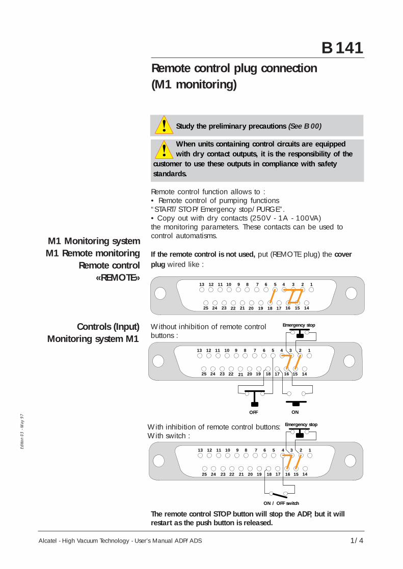
Controls (Input)Monitoring system M1
Remote control function allows to :• Remote control of pumping functions“START/STOP/Emergency stop/PURGE”.• Copy out with dry contacts (250V - 1A - 100VA)the monitoring parameters. These contacts can be used tocontrol automatisms.
If the remote control is not used, put (REMOTE plug) the coverplug wired like :
The remote control STOP button will stop the ADP, but it willrestart as the push button is released.
12345678910111213
141516171819202122232425
12
Arrêt
345678910111213
141516171819202122232425
Marche
Arrêt d'urgence
12
Interrupteur MA/AR
345678910111213
141516171819202122232425
Arrêt d'urgenceWith inhibition of remote control buttons:With switch :
Without inhibition of remote controlbuttons :
When units containing control circuits are equippedwith dry contact outputs, it is the responsibility of the
customer to use these outputs in compliance with safetystandards.
Study the preliminary precautions (See B 00)
Emergency stop
OFF ON
Emergency stop
ON / OFF switch

Alcatel - High Vacuum Technology - User’s Manual ADP/ADS2/4
Editi
on 0
3 - M
ay 9
7
B 141Remote control plug connection(M1 monitoring)
Available outputs ofMonitoring system M1
Dry contacts : 250 V - 1 A - 100 VAThese contacts open in the presence of a fault.Two contacts available for each fault type.
Available outputs : Contact 1 Contact 2
1 - Major faults :RT1 switched off 12 - 13 8 - 21
2 - Pump working :KM1 switched off 9 - 22 6 - 19
3 - Temperature faults :T° > 50° C 10 - 11 7 - 20
12
24V
345678910111213
141516171819202122232425
Arrêt d'urgence
+-
State of «Emergency»Monitoring system M1
The front panel emergency stop button copy out contact isavailable between 7 and 8 contacts of “emergency“ plugat the rear of the monitoring system.
REMOTE
RT1 CB 1
Prise EMERGENCY
EMERGMOTOR TEMP.WATERVALVE
Emergency stop
EMERGENCY Plug
With external power supply :

B 141
Alcatel - High Vacuum Technology - User’s Manual ADP/ADS
Remote control plug connection(M1 monitoring)
3/4
Editi
on 0
3 - M
ay 9
7
M1 Monitoring systemon modular ADP
Remote control«REMOTE»
Control (Inputs)Monitoring system M1
If the remote control is not used, put (REMOTE plug) the coverplug wired like :
The remote control STOP button will stop the ADP, but it willrestart as the push button is released.
1 2 3 4 5 6 7 8 9 10 11 12 13 14 15 16
18 19 20 21 22 23 24 25 26 27 28 29 30 31 32 33
17
34 35 36 37 38 39 40 45 46 48 4941 47 5042 43 44
Arrêt
Marche
Arrêt d'urgence
1 2 3 4 5 6 7 8 9 10 11 12 13 14 15 16
18 19 20 21 22 23 24 25 26 27 28 29 30 31 32 33
17
34 35 36 37 38 39 40 48 4941 47 5042 43 44 45 46
Arrêt d'urgence
1 2 3 4 5 6 7 8 9 10 11 12 13 14 15 16
18 19 20 21 23 24 25 26 27 28 30 31 32 33
17
34 35 36 37 38 39 40 48 4941 47 5042 43 44 45 46
Interrupteur MA/AR
22 29
With inhibition of remote control buttons:With switch :
Without inhibition ofremote control buttons :
Emergency stop
Emergency stop
Stop
ON / OFF switch
ON

B 141
Alcatel - High Vacuum Technology - User’s Manual ADP/ADS
Remote control plug connection(M1 monitoring)
4/4
Editi
on 0
3 - M
ay 9
7
Available outputs ofMonitoring system M1
Dry contacts : 250 V - 1 A - 100 VAThese contacts open in the presence of a fault.Two contacts available for each fault type.
Available outputs : Contact 1 Contact 2
1 - Major faults :RT1 switched off 12 - 13 8 - 21
2 - Pump working :KM1 switched off 8 - 10 14 - 15
3 - Temperature faults :T° > 50° C 5 - 7 35 - 36
Arrêt d'urgence
1 2 3 4 5 6 7 8 9 10 11 12 13 14 15 16
18 19 20 21 23 24 25 26 27 28 31 32 33
17
34 35 36 37 38 39 40 48 4941 47 5042 43 44 45 46
22 29
24VDC
+-
30
State of «Emergency»Monitoring system M1
The front panel emergency stop button copy out contact isavailable between 7 and 8 contacts of “emergency“ plugat the rear of the monitoring system.
REMOTE
RT1 CB 1
Prise EMERGENCY
EMERGMOTOR TEMP.WATERVALVE
Emergency stop
EMERGENCY Plug
With external power supply :
Alcatel - High Vacuum Technology - User’s Manual ADP/ADS
Editi
on 0
3 - M
ay 9
7
B 150RS 232 or RS 485 link wiring
1/2
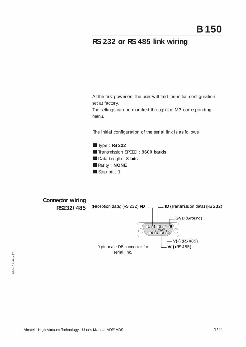
Connector wiringRS232/485
The initial configuration of the serial link is as follows:
Type : RS 232 Transmission SPEED : 9600 bauds Data Length : 8 bits Parity : NONE Stop bit : 1
At the first power-on, the user will find the initial configurationset at factory.The settings can be modified through the M3 correspondingmenu.
1 2 3 4 5
GND (Ground)
V(+) (RS 485)
TD (Transmission data) (RS 232)(Reception data) (RS 232) RD
V(-) (RS 485)
6 7 8 9
9-pin male DB connector forserial link.

Alcatel - High Vacuum Technology - User’s Manual ADP/ADS
Editi
on 0
3 - M
ay 9
7
1
59
61
9
6
5
B 150RS 232 or RS 485 link wiring
2/2
Examples of possibleconnection
Link RS232with a single
monitoring system M3
Multiple serial linkRS232
Serial link RS485
Several M3 monitoring systems may be connected on asingle link.
The multiple link is obtained by creating a loop:
Connect terminals 7 and 8 when the monitoring system is atthe end of the line.
The commands and messages reception syntax is dealt with ina special chapter (Contact Alcatel).
6
19
5
6
19
5
6
19
5
6
19
5
6
19
5
6
19
5
6
19
5

B 170Installation of silencer heating kit
Alcatel - High Vacuum Technology - User’s Manual ADP/ADS 1/2
Editi
on 0
1 -
May
98
To avoid the condensation of pumped gases, and therefore, theclogging of the silencer during the pump operation wich processessuch as: Aluminum etching, Polysilicon, LPCVD or PECVD Nitrid,Alcatel proposes a silencer heating kit including: • two heating belts (1) • two insulation sleeves (2)• a connection box (3)• a mains cable (4).
Consult the safety instructions (see B 00)
2
1
3
4

B 170Installation of silencer heating kit
The electrical power supply of the kit is not monitoredby the M3 controller (in case of an emergency stop,
the belt stays powered). Take the necessary precautions relatedto electrical safety.
Alcatel - High Vacuum Technology - User’s Manual ADP/ADS2/2
Editi
on 0
1 -
May
98
During the silencer heating kit installation, take allthe necessary precautions regarding the pumped gases
before to open the exhaust circuit of the pump. Refer also tothe safety instructions related to maintenance Section D 00.
Installation andelectrical connection
• Remove the silencer fromthe pump.• Install the two heating belts(1) using the tightening cords.
• Install the two insulationsleeves (2).
• Remount the silencer on the pump.• Connect the belts (1) to the power supply (3) after wiringthe cables on the plugs if necessary (provided with the kit orrecovered on the old belts in the case of maintenance). • Connect the power supply (3) to the installation.• Set the power supply switch to ”I”.The heating kit will be used during pumping of condensable gases.
Check the electrical compatibility between the kit andthe mains voltage.
Caution : Heating temperature = 130 °C. Take all the necessary precautions regarding burn risks.
2
1

C 10
Alcatel - High Vacuum Technology - User’s Manual ADP/ADS
Start-up of the M3 monitoring system
1/3
Editi
on 0
4 - M
ay 9
8
The functions of theparameter selection
and configuration keys
The keyboard is used to control the pump and configurethe parameters. The pump’s manual
control keys are locatedon the top line of thekeyboard.
The SET key is used tohave access to the pull-down menu to read ormodify parameters.
STOP START PURGE ROOTS
SET ENTER
WATER
FAULT
Touches de pilotage manuel
Touches de sélection et de configuration des paramètres
Voyants
Symbol Description Functions
• Used to have access toParameter setting mode the parameter setting mode
access key • Used to exit the various menuswithout validating the functions
• Used have access to :- the next or previous menu- the next or previous parameter
Selection keys in the displayed menu• Used to select or adjust the value
of the parameter selectedpreviously
Configuration • Used to validate the selection ofvalidation key a menu, parameter or valueENTER
SET
Manual control keys
Indicators
Parameter selection and configuration keys
Study the safety instructions(see B 00)
An insulating film protects the keys. Do not use hardobjects such as pens, screwdrivers, etc., which could
damage the key.

C 10
Alcatel - High Vacuum Technology - User’s Manual ADP/ADS
Start-up of the M3 monitoring system
2/3
Editi
on 0
4 - M
ay 9
8
Power ON :(Main switch of M3 to I)
Accessing to the parameterprogramming :The programming made atthe factory is protected by anaccess code which disablesthe entry of new parameters.
Display of the pump runningtime, the pump status and thedate when the monitoringhave been set for transport.
Press the key
Valid the codewith the key
Acces code can be personalized (see C 30)
The M3 monitoring system has been configured in the factoryaccording to the options and accessories defined during theorder.
Setting / Observations Action / Observations Display / Observations
SET
ENTER
75H LOC N2PUMPING STOPPED02/02/98 11 : 32 : 54
M3 VERSION 2.03
CODE : 0

C 10
Alcatel - High Vacuum Technology - User’s Manual ADP/ADS
Start-up of the M3 monitoring system
3/3
Editi
on 0
4 - M
ay 9
8
Press the key repeatedlyto have access tothe SETTING MENUValidate with the key
With the keymove through the menuto DATE/TIMEValidate with the key
Decrease or increase theselected parameter usingthe keys
Validate the settingusing the keyThis action validates thesetting and moves onto thenext parameter
Validate the settings and returnto the main menu withthe key
Press the key repeatedlyto have access tothe STORAGEValidate with the key
Press the key
Pumping cannot be started(Seconds counter is blocked)
Initializing the equipmentby updating the clock.
Set the STORAGE menu to savethe internal parameters duringtransport or prolonged storage.
Setting / Observations Action / Observations Display / Observations
ENTER
SET
ENTER
ENTER
ENTER
SET
Note : When you position the main switch to position I,the storage mode disappears automatically :Make a DATE/TIME setting (see previous paragraph)
DEFINITIONSETTING MENUMAINTENANCE MENUOPERATING TIME
DEFINITIONSETTING MENUMAINTENANCE MENUOPERATING TIME
PURGE PRESS. SENSORSERIAL LINKDATE/TIMETEMPERATURE UNIT
DATE/TIMEMM/DD/AA HH: MM: SS02/02/98 11 : 32 : 54
MAINTENANCE MENUOPERATING TIMESTORAGECHANGE CODING
STORAGEPUMPING STOPPED03/23/98 18 : 24 : 80

C 20
Alcatel - High Vacuum Technology - User’s Manual ADP/ADS
Setting the M3 monitoring systemparameters
Purpose of sensors
1/2
Editi
on 0
4 - M
ay 9
8
Purge sensor Signals insufficient gas purge during analert time, and stops pumping at the endof the alarm time.Signals exhaust overpressure when thepressure reaches 1450 mbar (silencerclogged) and stops the pump at1990 mbar.
Gas Signals a gas temperature variation at Temperature the exhaust with :sensor - an alert 1 when the temperature is less(Non TC version) than the alert 1 threshold
- an alert 2 when the temperature is greater than the alert 2 threshold withoutstopping the group.
Pump Temperature Allows to regulate ADP temperature.sensor on Signals a pump temperature variationTC version (an alert when temperature is less than
the alert threshold and an alarm whentemperature is greater than alarmthreshold).
Motor Monitors the power consumed by the power sensor machine by generating an alert followed
by an alarm as soon as the power isgreater than each of its thresholds;the pump is stopped immediately whenthe alarm threshold is exceeded.
E Analogic sensor Allows to monitor a voltage on an input contact with 2 adjustable thresholds.
E1 and E2 logic Allows to monitor a logic sensor duringsensors an alert time and stop pumping at the
end of the alarm time.

C 20
Alcatel - High Vacuum Technology - User’s Manual ADP/ADS
Setting the M3 monitoring systemparameters
2/2
Editi
on 0
4 - M
ay 9
8
Summary table ofmonitoring parameters
Max. and Min.thresholds :
The pump may be started. The operation monitoring dependson the fault programming. However, the M3 monitoring systemmay be customized according to the current application, byprogramming the parameters, pump stopped, of the variousmenus listed on C 30.
*Temperature regulation occurs 10°C below the alert threshold.
Mini Maxi Alert Alarm
mbar 600 900 860Purge sensormin 0 60 0 Disabled
Gas temperature sensor °C 0 170< 20° -> 160°
Pump θ° sensor (TC)* °C 20 130 110 120
Motor power sensor W 500 5000 2500 4000
E. analogical sensor mV 0 10000 Disabled Disabled
E1. logic sensor min 0 60 Disabled Disabled
E2. logic sensor min 0 60 Disabled Disabled
SENSORS UNIT THRESHOLD FACTORYCONFIGURATION

C 30
Alcatel - High Vacuum Technology - User’s Manual ADP/ADS
M3 Monitoring systemfunction table
1/3
Editi
on 0
4 - M
ay 9
8
DEFINITION INLET VALVE OPTIONANA. INPUT SELECTE1 LOGIC INPUTE2 LOGIC INPUTSYSTEM SELECTION
AUTOMATIC RESTARTINGROOTS CONTROLBUZZER CONTROL SELECT.PURGE CONTROL SELECT.THERMO CONTROLLEDFLOW N2 OPTION
Valid/DisabledValid/DisabledValid/DisabledValid/DisabledADS151/ADS301/ADS501/ADS801/1001ADP81/ADP81V/ADP31/ADS501VValid/DisabledValid/DisabledValid/DisabledValid/DisabledValid/DisabledValid/Disabled
( Tec
hnic
al m
odifi
catio
ns re
serv
ed )
Initial configuration (bold)
Other menusnext page

C 30
Alcatel - High Vacuum Technology - User’s Manual ADP/ADS
M3 Monitoring systemfunction table
2/3
Editi
on 0
4 - M
ay 9
8
( Technical modifications reserved )
SETTING PURGE FLOW SENSOR
TEMP. SENSOR
ADP POWER SENSOR
ANA. INPUT SENSOR
E1 LOGIC. SENSOR
E2 LOGIC. SENSOR
PURGE FLOW PROLONGED
PURGE PRESS. SENSOR
SERIAL LINK
DATE, TIMETEMPERATURE UNITPRESSURE UNIT
Alert timeAlarm time
If Thermo controlled“Disabled“:Alert 1 thresholdAlert 2 thresholdIf Thermo controlled“valid“:Alert thresholdAlarm threshold
Alert thresholdAlarm threshold
Alert thresholdAlarm threshold
Alert timeAlarm time
Alert timeAlarm time
0 to 120 min
600 to 900 mbar
TypeEchoAddressSpeedParityStop bit
Time/Date menuCelsius/Fahrenheitmbar, hPa, Torr, PSI
0 to 60 min/Disabled0 to 60 min/Disabled
0 to Alert 2Alert 1 to 170° C
20° to Alarm thresholdAlert threshold to 130°C
500 to Alarm thresholdAlert to 5000 W
0 to Alarm thresholdAlert threshold to 10 000 mV
0 to 60 min/Disabled0 to 60 min/Disabled
0 to 60 min/Disabled0 to 60 min/Disabled
Initial config. : 10 min
Initial config. 860 mbar
RS232/RS485/NETWORKValid/Disabled0 to 999300 - 9600Even/None/Odd1 or 2
Initial config. : °CInitial config. : mbar
Other menusnext page

Alcatel - High Vacuum Technology - User’s Manual ADP/ADS 3/3
Editi
on 0
4 - M
ay 9
8
C 30M3 Monitoring systemfunction table
MAINTENANCE MENU MAINTENANCE TIMEOVERHAUL ADPADP LP BEARINGSINSPECT SILENCEROVERHAUL ROOTS
1000/34000 h1000/17000 h1000/17000 h1000/34000 h
Using and key,
input the new codeand valide with
Initial Config :8500 h8500 h2500 h8500 h
OPERATING TIME DISPLAY
STORAGE
INPUT THE NEW CODE:CHANGE CODING
ENTER
( Technical modifications reserved )
DISPLAY LAST10 ALERTS
LAST ALERTS
DISPLAY LAST10 ALARMS
LAST ALARMS
LIST OF CUSTOMIZED PARAMETERS
CONFIGURATION

C 40
Alcatel - High Vacuum Technology - User’s Manual ADP/ADS
Use of the M3 monitoringfor pumping operation
1/2
Editi
on 0
4 - M
ay 9
8
• Pre-adjustements :- to ensure a gas purge as soon as the pumping starts, set the ‘’Select. CMD Purge’’ menu on disabled
- to start-up or stop the gas purge during pumping set the ‘’Select. CMD Purge’’ menu on valid. The purge will start or stop by pressing the ‘’PURGE’’ key
- to start-up the Roots at the same time as the ADP, set the ‘’Roots control’’ menu on disabled
- to start-up or stop the Roots while the ADP is running, set the ‘’Roots control’’ menu on valid. The Roots will start or stop by pressing the ‘’ROOTS’’ key.
• Start-up the pumping by pressing “START”, the monitoringsystem performs the following operations :
- opening the inlet valve (if preselection has been validated),- ADP pump start-up,- opening the water valve,- data capture and sensor processing,- opening the purge gas valve (if preselection has beenvalidated),
- Roots pump start-up.
At the same time the operatingparameters are shown.
15 H *N2* ROOTSCHECK PRESSURE 940 MBARGAS TEMP. / ADP TEMPADP POWER
Check therotational direction
of the pump, upon firststart-up
(See B 130)
STOP START PURGE ROOTS
SET ENTER
Study the safety precautions(voir B 00)
The performances and the operational safety of thisproduct are guaranteed provided that it is used in
normal operating conditions.
The pumps are equipped with an exhaust pressure monitoringsensor. When this is not used, it is the responsibility of the
user to prevent the risks related to excess pressure of the installation.

C 40
Alcatel - High Vacuum Technology - User’s Manual ADP/ADS
Use of the M3 monitoringfor pumping operation
2/2
Editi
on 0
4 - M
ay 9
8
During operation, the user is warned of an operatingincident by :
- one or more fault are displayed on the screen, alternatingwith monitoring parameters. When these faults areparameter programmable, the monitoring system triggersthe alert phase followed by the alarm phase. The periodfor these phases is programmable.
- indicators light and buzzer sounded, if option selected.- the fault contacts on the REMOTE connector at the rear ofthe monitoring unit are closed.
- pumping is stopped.A list of incidents is given in the chapter D.
Operation monitoring
Pumping shut-down
Remote control
Press the “STOP” key, the monitoring system performs thefollowing operations :
- pump stopping,- water valve closing,- injection of purge gas is continued during the shutdownphase (if programmed),
- when the pump is fitted with an exhaust valve or inlet valve,this valve is closed when pumping stops.
When the stoppage is caused by a power cut, automaticrestarting is possible if “AUTOMATIC RESTARTING” has beenenabled.
M3 monitor enables other operating modes, particularly controlby PC via RS 232 interface and RS 485 (see section B 150) orthe remote control via the connector Remote (see section B 140).
Avoid moving a pump in operation
When the pump has been configurated for automaticrestart after a power failure, it is the responsibility of the
user to take all the measures required to prevent risks resultingfrom this type of operation

C 50
Alcatel - High Vacuum Technology - User’s Manual ADP/ADS
Use of the M1 monitoring system
1/2
Editi
on 0
3 - M
ay 9
7
Pump equipped with theM1 monitoring system
and in local mode
Remote monitoringunit (M1)
Stopping pumping
Operating incidents
• Set the main switch to I, actuate the START switch :the pumping starts, the water valve opens and the greenindicator light goes on. (The hour counter is only increased whenthe pump is operating).• Adjust the water flow rate (see section B 120).
The remote monitoring unit is connected to the unit located onthe frame via a 5 or 10 m cable, connected at the front.In this case, all controls are made from the remote unit.The frame-mounted unit only contains the main switch, theemergency stop and the monitoring system indicator lights.
Actuate the STOP switch, the water valve closes; the pumpingstops.
The user is informed of any incidents by :• the fault indicator light which goes on (red),• the audible warning buzzer,• the fault contacts on the REMOTE connector at the rear ofthe monitoring system which close,• stopping of the pumping although the STOP command hasnot been given.
For the first pump start-up, check the rotational direction of the pump (see B 130)
Study the safety precautions (see B 00)
012345DEFAULT
TEMP
0
E
S T O P
ME R G E
NCY
5 or 10 m
Rear view
Avoid moving a pump in operation

C 50
Alcatel - High Vacuum Technology - User’s Manual ADP/ADS
Use of the M1 monitoring system
2/2
Editi
on 0
3 - M
ay 9
7
The M1 monitoring systemcan be remote controlled
The remote control function is performed by means of the“REMOTE” remote control connector at the rear of each fixedmonitoring unit.It is used for :• The remote control of the pump “START/STOP/ EmergencyStop” functions.• Copying monitoring parameters in dry contact form(250 V - 1 A - 100 VA). These contacts may be used forcontrolling automatic control systems. (see section B 140).

D 00
Alcatel - High Vacuum Technology - User’s Manual ADP/ADS
Safety instructions related to maintenance
1/2
Editi
on 0
4 - M
ay 9
8
Standard precautions before any maintenance operation :Before performing a maintenance operation, switch off
the pump by setting the main switch to “0” and disconnectthe mains cable.
This chapter describes the main preventive maintenanceoperations and provides a guide for first diagnosis in the eventof an incident.
CAUTION : before any operation, check the pumping conditions of the installation : toxicity, corrosion, possible
radioactivity of the pumped gases.
Product tightness is guaranteed upon leaving the factory for normal operating conditions. It is the responsibility of the user
to ensure that the level of tightness is maintained when pumping dangerous gases.
Depending on the case, we recommend :
• to purge the installation with dry nitrogen. The flush is performedautomatically when the pump is stopped (normal stop, or due toa fault) if a maintained level of purge gas has been programmed.Otherwise, proceed as follows:- If the pump is remote controlled, remove the connections onthe REMOTE connector, at the rear of the monitor, and connectthe plug connector (supplied with the machine) instead.- Adjust the parameters of the M3 monitor and program amaintained level of purge gas for 10 minutes.- Press START, followed by STOP on the front panel. The flush isperformed after the machine is stopped.• to wear gloves, protective glasses and, if necessary, a breathingmask.• to ventilate the premises well.• not to dispose of residue but, if necessary, to have it destroyed bya qualified organization.

D 00
Alcatel - High Vacuum Technology -User’s Manual ADP/ADS
Safety instructions related to maintenance
2/2
Editi
on 0
4 - M
ay 9
8
• Certain gases can become corrosives and toxic when trappedin oil. Always wear protective gloves when handling used anddirty pump oil, drain it into a closable container, and do notbreathe the fumes of the oil. Always use fully self-containedbreathing apparatus.
• When the silencer is maintained, avoid any contact with thereaction by-products (deposit, powder..) strongly corrosive: weargloves even a breathing mask. Cleaning procedure can produceviolent reactions and dangerous gas releases. We recommend toventilate the premises well and disassemble the equipment undera suction hood.
• Always dispose of used dirty oil, or sub-products properly andin compliance with all local, state and federal environmental lawsand regulations.
After a complete maintenance operation, on the pump or on theinstallation, it is recommended to perform a tightness test with
helium.

D 10
Alcatel - High Vacuum Technology - User’s Manual ADP/ADS
First level of maintenance
1/2
Editi
on 0
4 - M
ay 9
8
Study the safety instructions related to maintenance (See D 00).
When a problem occurs, the user is informed by :
- the relevant fault indicator light which goes on,- the audible warning buzzer,- the fault contacts on the REMOTE connector at the rear ofthe monitoring system which close,- the stopping of the pumping although the STOP command has notbeen given,- the display of fault message on the screen of the M3 monitoringsystem,- a message via the RS 232 or RS 485 link on a micro-computer.
Location of electricalcomponents
M1 Monitoring unit (Rear panel)J1 J2 J3
CB1TR1
M3 Monitoring unit (Rear panel)
J1J4J3J2
J6
J5
CB1RT1CB2
J5
RT1TR1
CB2
ADS opened
CB1 : circuit breakerCB2 : Ext* 24V circuitbreakerRT : ADP and Roots powercircuit breakersTR1 : Int* transformerMonitoring
ADS Unit
RT1
RT2
RT3 for ADS801/1001
CB1 CB2
* Int : internal

D 10
Alcatel - High Vacuum Technology -User’s Manual ADP/ADS
First level of maintenance
2/2
Editi
on 0
4 - M
ay 9
8
Preventivemaintenance with
monitoring system M1
Maintenance timemonitoring with
monitor system M3
The overall operating time of the machine can be read onthe front of the monitoring units (M1).This is also used to calculate the operating time of the variouscomponents which require maintenance.
The replacement frequency of certain components dependsdirectly on the type of process used. (See section D 20)
Maintenanceoperations
Depending on the maintenance parameters programmed,when the operating time before maintenance has expired,the screen display alternates between operating parametersand the message “ALERT MAINTENANCE”, the “FAULT”indicator is lit.Press the “SET” button during pumping and the operating timesfor components are displayed in turn.This information can be red at any time using the“Operating time” menu. Perform maintenance on the relevantparts.
See Section E

D 20
Alcatel - High Vacuum Technology - User’s Manual ADP/ADS
Maintenance frequency
1/3
Editi
on 0
4 - M
ay 9
8
For processes 1 (See section B 120)
LP bearing Minor kitreplacement 30 min (31/81) 090576
Full overhaul 10 H* Major kit (31) 04016212 H* Major kit (81) 061925
ALCATEL 113 oil 064657(0.5 L)
Full overhaul 8 H* Major kit (151) 100068 051940Major kit (301/601) 090839ALCATEL 113 oil 064657(0.5 L) Qty : 2 for 301 & 601
Full overhaul 12 H* Major kit 101109ALCATEL 113 oil 064657(0.5 L) Qty : 6
A : ADP 31 - ADP 81 Maintenance * Testing and cleaning time not included A+B : ADS 151 / 301 / 501 Maintenance ** For oil filling, see section B 50A+C : ADS 801/1001 Maintenance
Maintenance times can change according to processes and equipments used.
8500
H
2500
0 H
1300
0 H
AA
DP
31 -
AD
P 81
BRo
ots
151
- 301
- 60
1C
Root
s 10
01/1
501
Timerequired Part
number
Specifictool
CommentsDescription
Equipment requiredDescription
2 oil fillingsfor 301 et 601
**
6 oil fillings**
ConsultAlcatel
ConsultAlcatel
**

D 20
Alcatel - High Vacuum Technology -User’s Manual ADP/ADS
Maintenance frequency
2/3
Editi
on 0
4 - M
ay 9
8
For processes 2 (See section B 120)
Silencer cartridgecontrol (1) 15 min Silencer cartridge 040095
LP bearing Minor kitreplacement 30 min (31/81) 090576
Full overhaul 10 H* Major kit (31) 04016212 H* Major kit (81) 061925
ALCATEL 113 oil 064657(0.5 L)
Full overhaul 8 H* Major kit (151) 100068 051940Major kit (301/601) 090839ALCATEL 113 oil 064657(0.5 L) Qty : 2 for 301& 601
Full overhaul 12 H* Major kit 101109ALCATEL 113 oil 064657(0.5 L) Qty : 6
A : ADP 31 - ADP 81 Maintenance * Testing and cleaning time not included A+B : ADS 151 / 301 / 501 Maintenance ** For oil filling, see section B 50A+C : ADS 801/1001 Maintenance
Maintenance times can change according to processes and equipments used.
(1) With TC version and silencer heating, the maintenance of the silencer can be extandedto 8500 h.
4200
H
1700
0 H
8500
H
AA
DP
31 -
AD
P 81
BRo
ots
151
- 301
- 60
1C
Root
s 10
01 -
1501
Timerequired Part
number
Specifictool
CommentsDescription
Equipment requiredDescription
2 oil fillingsfor 301 et 601
**
6 oil fillings**
ConsultAlcatel
ConsultAlcatel
Equippedsilencer available
Ref : 100210
**

D 20
Alcatel - High Vacuum Technology - User’s Manual ADP/ADS
Maintenance frequency
3/3
Editi
on 0
4 - M
ay 9
8
For processes 3 (See section B 120)
Silencer cartridgecontrol 15 min Silencer cartridge 040095
LP bearing Minor kitreplacement
30 min (31/81) 090576
Full overhaul 10 H* Major kit (31) 04016212 H* Major kit (81) 061925
ALCATEL 113 oil 064657(0.5 L))
Full overhaul 8 H* Major kit (151) 100068 051940Major kit (301/601) 090839ALCATEL 113 oil 064657(0.5 L) Qty : 2 for 301& 601
Full overhaul 12 H* Major kit 101109ALCATEL 113 oil 064657(0.5 L) Qty : 6
A : ADP 31 - ADP 81 Maintenance * Testing and cleaning time not incluedeA+B : ADS 151 / 301 / 501 Maintenance ** For oil filling, see section B 50A+C : ADS 801/1001 Maintenance
Maintenance times can change according to processes and equipments used.
2100
H
8500
H42
00 H
AA
DP
31 -
AD
P 81
BRo
ots
151
- 301
- 60
1C
Root
s 10
01 -
1501
Tmerequired Part
number
Specifictool
CommentsDescription
Equipment requiredDescription
**
**
Equippedsilencer available
Ref : 100210
**
Included infull overhaul
ConsultAlcatel
ConsultAlcatel

D 30
Alcatel - High Vacuum Technology - User’s Manual ADP/ADS
Diagnosis and troubleshooting
1/1
Editi
on 0
3 - M
ay 9
7
Pump does not start . . . . . . . . . . . . . . . . . . .
The pump is running and then is showingan alert or alarm message(followed by the pumps stopping) . . . . . . . . . .
The pump is running (no message) . . . . . . . . .
D 40
D 50
D 60

Alcatel - High Vacuum Technology - User’s Manual ADP/ADS 1/4
Editi
on 0
4 - M
ay 9
8
D 40Pump does not start
INCIDENT CAUSE TROUBLESHOOTING
No mains
Switch it onVersion before 96/12:Push on the red button untillzero and release.Since 97/01Push on the blue buttonuntill zero.
Isolating switch is off
Check the calibrationSwitch it on
CB1 breaker switched off
NO
NO
Call Alcatel customer serviceOther problem
NO
Call Alcatel customer service
The display is not lighting upor no display
The keyboard is not working
Check power supply

Alcatel - High Vacuum Technology -User’s Manual ADP/ADS2/4
Editi
on 0
4 - M
ay 9
8
D 40Pump does not start
Configure for “ADS“and/or disable Roots
Bad M3 configuration
Check the settingCommand “Roots valid“ notprogrammed
Press on key “Roots“
NO
NO
NO
Check presence or connectjumper plug RP
No * presencenear Roots
NO
Check the connection
Pressing on “Start“ doesnot start-up the pump
Roots is not running
Roots does not run and“Roots“ message is
displayed
INCIDENT CAUSE TROUBLESHOOTING
“Roots “J3 plug bad connected
Call Alcatel customer serviceDefective managementboard
NO
Check the connection“ADP“ plugbad connected
ADP does not run
Call Alcatel customer serviceProblem on M3
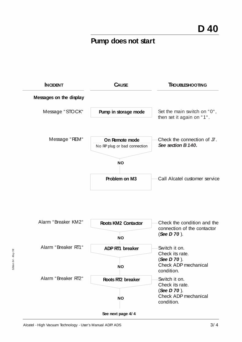
D 40
Alcatel - High Vacuum Technology - User’s Manual ADP/ADS 3/4
Editi
on 0
4 - M
ay 9
8
Call Alcatel customer serviceProblem on M3
NO
NO
NO
NO
See next page 4/4
Pump does not start
Check the connection of J7.See section B 140.
Set the main switch on “0“,then set it again on “1“.
On Remote modeNo RP plug or bad connection
Pump in storage mode
Check the condition and theconnection of the contactor(See D 70 ).
Roots KM2 Contactor
Messages on the display
Alarm “Breaker KM2“
Message “REM“
Message “STOCK“
Switch it on.Check its rate.(See D 70 ).Check ADP mechanicalcondition.
ADP RT1 breakerAlarm “Breaker RT1“
Switch it on.Check its rate.(See D 70 ).Check ADP mechanicalcondition.
Roots RT2 breakerAlarm “Breaker RT2“
INCIDENT CAUSE TROUBLESHOOTING

D 40
Alcatel - High Vacuum Technology -User’s Manual ADP/ADS4/4
Editi
on 0
4 - M
ay 9
8
Pump does not start
See D 80Exhaust pressure≥ 1450 mbar
Check the main power.Main power is not correct
Alarm “Pressure“
“Starting phase“
No message displayed onthe screen
INCIDENT CAUSE TROUBLESHOOTING
NO
NO
Check the condition and theconnection of the contactor(See D 70 ).
ADP KM1 ContactorAlarm “Breaker KM1“
Switch it on(See D 70 ).
Emergency switchAlarm “Breaker EMO“
Call Alcatel customer serviceProblem on M3

Alcatel - High Vacuum Technology - User’s Manual ADP/ADS
Editi
on 0
4 - M
ay 9
8
D 50The pump is running and then isshowing an alert or alarm message(followed by the pump stopping)
1/9
Alert “Pressure“
Alert “Pressure“
INCIDENT CAUSE TROUBLESHOOTING
NO
Check the connection(See D 80)
Exhaust pressure= 500 mbar
See D 80Exhaust pressure> 1450 mbar
See D 80Exhaust pressure> 1990 mbar

Consumption higher thanalert threshold or no power
See D 100“Consumption“ Alert“Consumption“ Alarm
Alcatel - High Vacuum Technology -User’s Manual ADP/ADS
Editi
on 0
4 - M
ay 9
8
D 50The pump is running and then isshowing an alert or alarm message(followed by the pump stopping)
2/9
INCIDENT CAUSE TROUBLESHOOTING
NO
See D 90θ gas lower thanalert threshold 1
Check the connectionSensors not connectedθ gas = 170°C
NO
NO
See D 90Problems onplatinium sensor
See D 90θ gas higher thanalert threshold 2
“Gas Temp.“ Alert

Alcatel - High Vacuum Technology - User’s Manual ADP/ADS
Editi
on 0
4 - M
ay 9
8
D 50The pump is running and then isshowing an alert or alarm message(followed by the pump stopping)
3/9
INCIDENT CAUSE TROUBLESHOOTING
NO
See D 110Insufficent water flow
Check the connectionSensor not connected
NO
NO
Call Alcatel customer serviceSensor out of order
Call Alcatel customer serviceProblem on M3
“Water flow“ Alert
Clean the flowmeterDeposits in the flowmeterUnreadable flowmetergraduation (blocked ball)
Check the voltageMains voltage variation(± 15%)
“Power supply“ Alert

D 50
Alcatel - High Vacuum Technology -User’s Manual ADP/ADS
The pump is running and then isshowing an alert or alarm message(followed by the pump stopping)
4/9
Editi
on 0
4 - M
ay 9
8
“Pump temp.“ Alarm
NO
See D 91Pump θ higher thanalert threshold
See D 91
“Pump temp.“ Alert
Problem on the platiniumsensor
See D 91Problem on the platiniumsensor
NO
See D 91Pump θ higher thanalarm threshold
Check the wiringSensor not connectedθ gas = 170°C
NO
INCIDENT CAUSE TROUBLESHOOTING

Alcatel - High Vacuum Technology - User’s Manual ADP/ADS 5/9
Editi
on 0
4 - M
ay 9
8
D 50The pump is running and then isshowing an alert or alarm message(followed by the pump stopping)
“Motor temp.“ Alarmθ ADP motor ≥ 65°
INCIDENT CAUSE TROUBLESHOOTING
NO
See D 110Cooling problems
See E 50ADP mechanical problems
NO
“Motor temp.“ Alertθ ADP motor ≥ 52°
Call Alcatel customer serviceDefect does not disappear
NO
Call Alcatel customer serviceDefect does not disappear
NO
See D 110Cooling problems
See E 50ADP mechanical problems

Alcatel - High Vacuum Technology -User’s Manual ADP/ADS6/9
Editi
on 0
4 - M
ay 9
8
D 50
NO
See D 80Exhaust pressureP = 500 mbar
See D 80500 mbar < P < Pres. threshold
NO
See D 80Flowmeter bad set
See D 80No nitrogen
Alert or alarm “Purge N2“
Alert and alarm are swit-ched on according to the
delays programmed in M3configuration
Without flow purgesensor option
With flow purgesensor option
The pump is running and then isshowing an alert or alarm message(followed by the pump stopping)
INCIDENT CAUSE TROUBLESHOOTING

Alcatel - High Vacuum Technology - User’s Manual ADP/ADS 7/9
Editi
on 0
4 - M
ay 9
8
D 50The pump is running and then isshowing an alert or alarm message(followed by the pump stopping)
INCIDENT CAUSE TROUBLESHOOTING
NO
Reset M3 configurationValid input afterconfiguration and not used
Check the correspondingvoltage (See D 130)
Problem on thedisplay/voltage
NO
Set the thresholdsThresholds not properly set
“Analogic input“Alert or alarm
Check the connection(See D 130)
Connection problems
NO
Reset M3 configurationValid input afterconfiguration and not used
Check the sensors(See D 140)
Sensor problems
NO
Set the delaysDelay not properly set
“E1 logic“ or “E2 logic“Alert or alarm

Alcatel - High Vacuum Technology -User’s Manual ADP/ADS8/9
Editi
on 0
4 - M
ay 9
8
D 50The pump is running and then isshowing an alert or alarm message(followed by the pump stopping)
NO
Reset M3 configurationValid option afterconfiguration and not used
Check the compressed airsupply.Check the valve condition.
Valve does not close whenpump is stopping
NO
See D 150Contact problems
“Valve option“ Alert
NO
Reset M3 configurationValid option afterconfiguration and not used
Check the compressed airsupply.Check the valve condition.
Valve does not open whenpump is starting
NO
See D 150Contact problems
“Valve option“ Alarm
INCIDENT CAUSE TROUBLESHOOTING

Alcatel - High Vacuum Technology - User’s Manual ADP/ADS 9/9
Editi
on 0
4 - M
ay 9
8
D 50The pump is running and then isshowing an alert or alarm message(followed by the pump stopping)
INCIDENT CAUSE TROUBLESHOOTING
NO
Valid option(ADP 81V, ADS 801/1001
or ADS 501V)when it is not necessary
Pump is stopped
NO
Check the connection.(See D 160)
Wiring problems
Perform maintenanceoperation and reset thecorresponding time.Check the maintenancethresholds.
The maintenance thresholdof a parameter is reached
“Variator“ Alert
“Maintenance“ Alert(ADP, Bearings, Silencer
or Roots)
Check variator parameteron ADS 801.(See D 160)
Reset M3 configuration.

Alcatel - High Vacuum Technology - User’s Manual ADP/ADS 1/1
Editi
on 0
4 - M
ay 9
8
D 60The pump is running - No message
NO
Maintenance ADPCall Alcatel customer service
Polluted or filled in pumps
Maintenance ADPCall Alcatel customer service
Internal oil leaks
Mechanical noise
No N2 purge
NO
Maintenance ADPCall Alcatel customer service
Damaged ball bearings
Maintenance ADPCall Alcatel customer service
Rotors seizing
NO
Maintenance ADPCall Alcatel customer service
Unsynchronized gears
Reset M3 configuration orset the purge manually.
Bad configuration
INCIDENT CAUSE TROUBLESHOOTING
Bad vacuumor no vacuum

D 70
Alcatel - High Vacuum Technology - User’s Manual ADP/ADS
“Breaker …“ Alarm
“Breaker KM2“ AlarmRoots KM2 Contactor
• Check the breaker CB2, on M3 rear panel
• If the message still remains, call Alcatel customer service
1/2
Editi
on 0
4 - M
ay 9
8
“Breaker RT1“ AlarmADP RT1 Breaker
Set the plug and the strap
Call Alcatel customer service
NO
NO
- Check its position- Check ADP mechanicalcondition (See E 50)- Check that the silencer is not clogged (See E 30).
RT 1 breaker is not inposition 1
No wattmeter plug and itsstrap between 4 & 6
Problem on M3
“Breaker RT2“ AlarmRT2 Roots breaker
NO
- Check its position- Check Roots mechanicalcondition
Call Alcatel customer service
RT 2 Roots braeker is noton position 1
Problem on M3
Alcatel - High Vacuum Technology -User’s Manual ADP/ADS2/2
Editi
on 0
4 - M
ay 9
8
D 70“Breaker …“ Alarm
“Breaker KM1“ AlarmADP KM1 contactor
• Check CB2 breaker at the rear of M3.(see D 10 ).
• Check the strap presence between the pins 41, 42, 43and 44 on remote plug. (see B 140).
• If the defect still remains, call Alcatel customer service.
“Breaker EMO“ AlarmEmergency stop
• Check that the emergency stop button is not tripped (unlockit by rotating 1/4 of turn).
• If the defect still remains, call Alcatel customer service.
D 80
Alcatel - High Vacuum Technology - User’s Manual ADP/ADS
“Pressure“ Alert and alarm“N2 Purge“ Alert and alarm
1/2
Editi
on 0
4 - M
ay 9
8
Exhaust pressure higherthan threshold
“Pressure“ Alert and alarm
• Check the nitrogen pressure setting according tosection B 120.
• Check that the silencer, the pipe to exhaust are notclogged.
• If the defect still remains, call Alcatel customer service.

D 80
Alcatel - High Vacuum Technology -User’s Manual ADP/ADS
“Pressure“ Alert and alarm“N2 Purge“ Alert and alarm
2/2
Editi
on 0
4 - M
ay 9
8
Exhaust pressure levelbetween 500 mbar and
threshold set“N2 Purge“ Alert and alarm
Without Nitrogen flowsensor option
With Nitrogen flowsensor option
(The flowmeter is connectedinstead if E2. Log.)
- Either check the connection, the display and nitrogen pressuresetting (idem exhaust pressure too high see page 1/2).
- If there is no N2 pressure, check nitrogen supply, connections,electrovalve and the coil and its connection.
- If the incident is still present, there is another problemon the M3: call Alcatel customer service.
- Check nitrogen supply, electrovalve and its coil.
- Check the nitrogen detector setting.
- Check the nitrogen detector wiring by shunting pins 23 & 24of J5.
Check that the sensor is properly connected.
- Test the connection and the display (idem exhaust pressuretoo high see page 1/2).
- If the incident is still present, call Alcatel customer service.
NO
Check the wiring.The defect disappears
Call Alcatel customer service.Problem on M3
Exhaust pressure= 500 mbar
D 90
Alcatel - High Vacuum Technology - User’s Manual ADP/ADS
“Gas temp.“ Alert
1/1
Editi
on 0
4 - M
ay 9
8
- Check the thresholds.
- Check the flowrate, the kind and the concentration of pumpedgases.
- Check that the exhaust pipe is not clogged.
- Check the display :• θ ambient when pump is stopped.• θ : 100°C in continuous operation.
- Check the wiring and the sensor : the resistance betweenpins 1 & 2 of J6 must be between 100 and 160 Ω.(J6 unpluged)
• 0°C : 100 Ω• 20°C : 107,8 Ω• 50°C : 119,4 Ω• 80°C : 130,9 Ω• 100°C : 138,5 Ω• 157°C : 160 Ω
- If the sensor is OK, there is another problem on the M3: call Alcatel customer service.

D 91
Alcatel - High Vacuum Technology - User’s Manual ADP/ADS
“Pump temp.“ Alert
1/1
Editi
on 0
1 - M
ay 9
8
- Check the thresholds.
- Check the display :• θ ambient when pump is stopped.• θ : 100°C in continuous operation.
- Check the wiring and the sensor : the resistance betweenpins 1 & 2 of J6 must be between 100 and 160 Ω.(J6 unpluged)
• 0°C : 100 Ω• 20°C : 107,8 Ω• 50°C : 119,4 Ω• 80°C : 130,9 Ω• 100°C : 138,5 Ω• 157°C : 160 Ω
- Check the cooling circuit.
- If the sensor is OK, there is another problem on the M3: call Alcatel customer service.

Invert two phases on mains plug J1
Call Alcatel customer service.
D 100
Alcatel - High Vacuum Technology - User’s Manual ADP/ADS
“Consumption“ Alert and alarm
1/1
Editi
on 0
4 - M
ay 9
8
Consumed power higher thanalert or alarm thresholds
- Check the threshold setting.
- Check the flowrate, the kind and the concentration of pumpedgases.
- Check that exhaust pipe are not clogged.
- Check that there is no mechanical problem (seizing), orfilling in in the pumping line.
- Check LP bearings.
- Check the rotational direction of the pump.
- If the incident is still present, call Alcatel customer service.
Consumed power = 0 W
NO
Rotational direction of thepump not correct
Problem on M3

D 110
Alcatel - High Vacuum Technology - User’s Manual ADP/ADS
“Water flowrate“ Alert
1/1
Editi
on 0
4 - M
ay 9
8
Insufficent water flow
No water flow
Water flow OK
- Check the flowmeter setting according to section B 120.
- Check that the electrovalve, the flowmeter or the pipes are notclogged.
- Check that there is no leak.
- Either check the water supply and the connections.
- Check the connection and the water valve coil condition.
NO
Remake the wiring.Change the setting of flowcontroller(see A 30 rep. 12)
The defect disappearsCheck the wiring of theflowmeter by shunting
the pins9 and 10 of J5
Call Alcatel customer service.Problem on M3
CAUSE TROUBLESHOOTING

- Check the water flowrate in the pump (see D 110).
- Check the motor temperature.
- Check the sensor and the wiring by shunting pins 21 & 22of J5.
- Check the sensor and the connection by shunting pins19 & 20 of J5.
D 120
Alcatel - High Vacuum Technology - User’s Manual ADP/ADS
“Motor temp.“ Alert or alarm
1/1
Editi
on 0
4 - M
ay 9
8
ADP motor temperaturehigher than the thresholds
Case of an alert
Case of an alarm
NO
Call Alcatel customer service.Problem on M3
NO
Problem on M3
The defect disappears Remake the wiring or change the sensor
Remake the wiring(see B 80)
The defect disappears
Call Alcatel customer service.

D 130
Alcatel - High Vacuum Technology - User’s Manual ADP/ADS
“Analogic input“ Alert or alarm
1/1
Editi
on 0
4 - M
ay 9
8
Wiring or displayproblem
NO
Problem on analogical sensor
Check the threshold settingSee C 30
Check the status of analogical sensor (Customer one)
Check the displayaccording to the DC input
voltage between pins 14 & 15 of J6 (15 = 0V)
Call Alcatel customer service.

D 140
Alcatel - High Vacuum Technology - User’s Manual ADP/ADS
“E1 logic“ Alert or alarm or“E2 logic“ Alert or alarm
1/1
Editi
on 0
4 - M
ay 9
8
Sensor or connectionproblem
E1 logic
E2 logic
NO
Remake the wiring :it must be continuity between pins 11 and 12 of J5.Check the sensor status.Call Alcatel customer service.
The defect disappears
Problem on M3
NO
Remake the wiring :it must not be continuitybetween pins 23 and 25 of J5.
The defect disappears
Problem on M3
Shunt the sensor
Check the threshold setting See C 30
Unplug the sensor
Call Alcatel customer service.
Call Alcatel customer service.

D 150
Alcatel - High Vacuum Technology - User’s Manual ADP/ADS
“Valve option“ Alert and alarm
1/1
Editi
on 0
4 - M
ay 9
8
Contact problem
Alert
Alarm
NO
Remake the wiring andcheck valve contact condition.
No defect at pump stop
Problem on M3
NO
No defect at pump start up
Call Alcatel customer service.Problem on M3
Check the wiring by shunting pins 7 & 8 of J5.
Check the configuration of M3 parameters ( See C 30)
Check the wiring by shunting pins 5 & 6 of J5.
Call Alcatel customer service.
Remake the wiring andcheck valve contact condition.

Configure onADS 801/1001, ADS 501Vor ADP 81V
D 160
Alcatel - High Vacuum Technology - User’s Manual ADP/ADS
“Variator“ Alarm
1/1
Editi
on 0
4 - M
ay 9
8
NO
Check the configuration ofM3 parameters (See C 30)
Problem on M3 Call Alcatel customer service.

Alcatel - High Vacumm Technology - User’s Manual ADP/ADS
Pump draining(Roots : front and rear casings)
Editi
on 0
3 - M
ay 9
7
E 20
1/1
ROOTS
fill plug
drain plug
oil level indicator
ADP
Housing oil replacement:
Unfasten the fill plug in order to eliminate any excess pressure inthe housing.
Remove the drain plug and allow the used oil to flow into a container(capacity: 0.5 litre).
Caution: the Roots is equipped with 2 housings. Repeat the operationfor each housing.
Replace the drain plug and the remove the fill plug.
Introduce the quantity of new oil required (see Section B 50).
10
10
Study the safety precautions before intervention. (See sheet D 00)
Certain gases become corrosive and toxic when trapped in oil. Always wear protective gloves when handling used and dirty pump
oil, drain into a closable container, and do not breathe the fumes of the oil. Always use fully self-contained breathing apparatus.
Always dispose of used or dirty oil, or sub-products properly and incompliance with all local, state and federal environnemental laws and
regulations.

1/3
Silencer maintenance
E 30
Alcatel - High Vacuum Technology - User’s Manual ADP/ADS
Remove the side covers See section B 20 and remove the silencer backplate located on
the rear panel of the pumping unit.
Disconnect the silencer from the pump exhaustconnector by removing the clamping ring and the sealsupport ring. (Access via one of the side openingslocated at the bottom of the frame)
Remove the assembly (silencer and outlet tube) fromthe rear of the machine.
Reinstall a complete assembly (equippedsilencer and outlet tube).
Reinstall the backplate to the rear of the pumpingunit and the side covers. Perform the maintenanceof the replaced parts on a bench.
Editi
on 0
4 - M
ay 9
8
SEE FOLIO 2
Consult the standard precautions before intervention - see Section D 00
For quicker interventions and special precaution during cleaning, it isrecommended to replace all the parts (equipped silencer and outlet tube)and repair the replaced parts on a bench.
REPLACEMENT FREQUENCY
The ADP pump silencer repair work frequency depends on the process used.Refer to the maintenance frequency tables. See Section D 20
SILENCER REPLACEMENT
When the silencer is maintained, avoid any contact with the reactionby-products (deposit powder..) strongly corrosive : wear gloves even a
breathing mask.

2/3
Silencer maintenance
E 30
Alcatel - High Vacuum Technology - User’s Manual ADP/ADS
Separate the outlet tube from the silencer.Remove the cover assembly.
Soak the silencer body in a bath of hot water and remove the depositlocated inside the silencer.Remove the cartridge and the Borelly washer.Loosen and remove the lock-nuts and the nuts to release the stop valve (5).Remove the two O-rings (3 and 4).
Clean all the parts in a bath of hot water using a cloth if necessary.Dry in the air or with compressed air.
Position the Borrelly washer (1) and install a new cartridge.
Reassemble the other parts by replacing the O-rings (3 and 4) with newseals.
Editi
on 0
4 - M
ay 9
8
6
5
12
34
PART CLEANING AND CARTRIDGE REPLACEMENT
Refer to the special precautions before any intervention - see Section D 00
Parts to be replacedSilencer maintenance kit Part No. 040095 (items 2, 3, 4)
Complete silencer (with cartridge)- Part No.: 100210
4

Editi
on 0
4 - M
ay 9
8
3/3
Silencer maintenance
E 30
Alcatel - High Vacuum Technology - User’s Manual ADP/ADS
RESSETTING MAINTENANCE PARAMETERS AFTER SILENCER MAINTENANCE OPERATION
Setting / Observations Action / Observations Display / Observations
When the maintenance of an element has been done, it is necessary to reset its meter tostop the warning and reset the functionnal delay of this element.
Press the key
Press the key until the code is obtained
Valid the codewith the key
Press the keyrepeatedly toaccess toMAINTENANCE MENU
Valid with the key
Press the keyrepeatedly toaccess the chosenMENUPress the key andpressing
The fresh screen appearsPress the keyrepeatedly
to reset the delay
Valid with the key
Accessing the parameterprogramming :The programming made atthe factory is protected byan acceess code whichdisables the entry of newparameters
Access in the“MAINTENANCE” menu
Acces to chosen parametermenu.
Reset the parameter.
ACCESS CODE
CODE : 0
DEFINITIONSETTING MENUMAINTENANCE MENUOPERATING TIME
SET
ENTER
ENTER
ENTER
ENTER
OVERHAUL ADPADP LP BEARINGSINSPECT SILENCEROVERHAUL ROOTS
COUNTER SETDURATION : 0 HMAXI : 17000 HMINI : 1000 H
STOP
STOP
or

E 50
Alcatel - High Vacuum Technology - User’s Manual ADP/ADS
Freeing up the ADP
1/1
Editi
on 0
3 - M
ay 9
7
If, after a prolonged stop, the ADP does not restart using the function STARTbecause of sub-products deposed inside the pump, it is possible to free it upmanually.
Consult the standard precautions before intervention. (See Section D 00)
Remove the protective cover (1) and removethe O-ring by removing the three M4 x 10 CHc
screws.
• ACCESS THE DRIVING SHAFT BEARING
3
Clean the O-ring and grease it lightly withvacuum grease.
Reinstall the O-ring and the protective cover.
• REFIT THE PROTECTIVE COVER
3
Using the box wrench, move the driving shaft inboth directions of rotation until free rotation is
obtained.
• FREEING UP BY ROTATING THE DRIVING SHAFT
21
Restart by pressing the “START” switch on the monitor.
• RESTART THE PUMP
1