Embed Size (px)
Citation preview
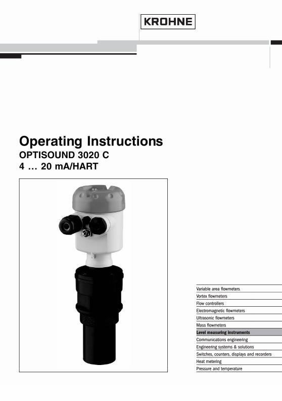
Operating InstructionsOPTISOUND 3020 C4 … 20 mA/HART
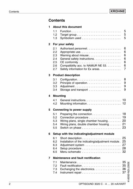
Contents1 About this document
1.1 Function . . . . . . . . . . . . . . . . . . . . . . . . . . . . . 51.2 Target group . . . . . . . . . . . . . . . . . . . . . . . . . . 51.3 Symbolism used . . . . . . . . . . . . . . . . . . . . . . . 5
2 For your safety2.1 Authorised personnel . . . . . . . . . . . . . . . . . . . . 62.2 Appropriate use. . . . . . . . . . . . . . . . . . . . . . . . 62.3 Warning about misuse . . . . . . . . . . . . . . . . . . . 62.4 General safety instructions . . . . . . . . . . . . . . . . 62.5 CE conformity . . . . . . . . . . . . . . . . . . . . . . . . . 62.6 Compatibility acc. to NAMUR NE 53. . . . . . . . . 62.7 Safety information for Ex areas. . . . . . . . . . . . . 7
3 Product description3.1 Configuration. . . . . . . . . . . . . . . . . . . . . . . . . . 83.2 Principle of operation . . . . . . . . . . . . . . . . . . . . 93.3 Adjustment . . . . . . . . . . . . . . . . . . . . . . . . . . . 93.4 Storage and transport . . . . . . . . . . . . . . . . . . . 9
4 Mounting4.1 General instructions. . . . . . . . . . . . . . . . . . . . . 104.2 Mounting information . . . . . . . . . . . . . . . . . . . . 12
5 Connecting to power supply5.1 Preparing the connection . . . . . . . . . . . . . . . . . 185.2 Connection procedure . . . . . . . . . . . . . . . . . . . 195.3 Wiring plans, single chamber housing . . . . . . . . 205.4 Wiring plans, double chamber housing . . . . . . . 215.5 Switch on phase . . . . . . . . . . . . . . . . . . . . . . . 23
6 Setup with the indicating/adjustment module6.1 Short description . . . . . . . . . . . . . . . . . . . . . . . 256.2 Installation of the indicating/adjustment module . 256.3 Adjustment system . . . . . . . . . . . . . . . . . . . . . 276.4 Setup procedure . . . . . . . . . . . . . . . . . . . . . . . 286.5 Menu schematic . . . . . . . . . . . . . . . . . . . . . . . 32
7 Maintenance and fault rectification7.1 Maintenance . . . . . . . . . . . . . . . . . . . . . . . . . . 357.2 Fault rectification . . . . . . . . . . . . . . . . . . . . . . . 357.3 Exchanging the electronics. . . . . . . . . . . . . . . . 367.4 Instrument repair . . . . . . . . . . . . . . . . . . . . . . . 37
2 OPTISOUND 3020 C - 4 … 20 mA/HART
Contents
30507-EN-050914

8 Dismounting8.1 Dismounting procedure . . . . . . . . . . . . . . . . . . 388.2 Disposal . . . . . . . . . . . . . . . . . . . . . . . . . . . . . 38
9 Supplement9.1 Technical data. . . . . . . . . . . . . . . . . . . . . . . . . 399.2 Dimensions . . . . . . . . . . . . . . . . . . . . . . . . . . . 449.3 Certificates . . . . . . . . . . . . . . . . . . . . . . . . . . . 46
Supplementary operating instructions manualsInformation:OPTISOUND 3020 C is available in different versions and issupplied order-specifically. Depending on the selected ver-sion, supplementary operating instructions manuals come withthe shipment. The supplementary operating instructions arestated in paragraph "3. Product description".
OPTISOUND 3020 C - 4 … 20 mA/HART 3
Contents
3050
7-EN-
0509
14
1 About this document1.1 FunctionThis operating instructions manual has all the information youneed for quick setup and safe operation of OPTISOUND 3020C. Please read this manual before you start setup.
1.2 Target groupThis operating instructions manual is directed to trainedpersonnel. The contents of this manual should be madeavailable to these personnel and put into practice by them.
1.3 Symbolism usedInformation, tip, noteThis symbol indicates helpful additional information.
Caution, warning, dangerThis symbol informs you of a dangerous situation that couldoccur. Ignoring this cautionary note can impair the person and/or the instrument.
Ex applicationsThis symbol indicates special instructions for Ex applications.
l ListThe dot set in front indicates a list with no implied sequence.
à ActionThis arrow indicates a single action.
1 SequenceNumbers set in front indicate successive steps in a procedure.
4 OPTISOUND 3020 C - 4 … 20 mA/HART
About this document
30507-EN-050914

2 For your safety2.1 Authorised personnelAll operations described in this operating instructions manualmust be carried out only by trained, specialised personnelauthorised by the operator. For safety and warranty reasons,any internal work on the instruments must be carried out onlyby personnel authorised by the manufacturer.
2.2 Appropriate useOPTISOUND 3020 C is a sensor for continuous levelmeasurement.
2.3 Warning about misuseInappropriate or incorrect use of the instrument can give rise toapplication-specific hazards, e.g. vessel overfill or damage tosystem components through incorrect mounting or adjustment.
2.4 General safety instructionsOPTISOUND 3020 C is a high-tech instrument requiring thestrict observance of standard regulations and guidelines. Theuser must take note of the safety instructions in this operatinginstructions manual, the country-specific installation standards(e.g. the VDE regulations in Germany) as well as all prevailingsafety regulations and accident prevention rules.
2.5 CE conformityOPTISOUND 3020 C is in CE conformity with EMC (89/336/EWG), fulfils the NAMUR recommendationNE 21 and is in CEconformity with LVD (73/23/EWG).Conformity has been judged acc. to the following standards:l EMC:
- Emission EN 61326: 1997 (class A)- Susceptibility EN 61326: 1997/A1: 1998
l LVD: EN 61010-1: 2001
2.6 Compatibility acc. to NAMUR NE 53OPTISOUND 3020 C meets NAMUR recommendation NE 53.
OPTISOUND 3020 C - 4 … 20 mA/HART 5
For your safety
3050
7-EN-
0509
14
The parameter adjustment of the basic sensor functions isindependent of the software version. The range of availablefunctions depends on the respective software version of theindividual components.The software version of OPTISOUND 3020 C can bedetermined as follows:l on the type label of the electronicsl via the indicating/adjustment module.You can find all software histories on our website www.krohne.com.
2.7 Safety information for Ex areasPlease note the Ex-specific safety information for installationand operation in Ex areas. These safety instructions are part ofthe operating instructions manual and come with the Ex-approved instruments.
6 OPTISOUND 3020 C - 4 … 20 mA/HART
For your safety
30507-EN-050914
3 Product description3.1 ConfigurationThe scope of delivery encompasses:l OPTISOUND 3020 C ultrasonic sensorl Documentation
- this operating instructions manual- Ex-specific safety instructions (with Ex versions) and, if
necessary, further certificates- Operating instructions manual "Indicating and adjust-
ment module" - optional
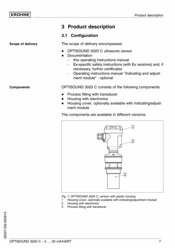
OPTISOUND 3020 C consists of the following components:l Process fitting with transducerl Housing with electronicsl Housing cover, optionally available with indicating/adjust-
ment moduleThe components are available in different versions.
1
2
3
Fig. 1: OPTISOUND 3020 C, version with plastic housing1 Housing cover, optionally available with indicating/adjustment module2 Housing with electronics3 Process fitting with transducer
Scope of delivery
Components
OPTISOUND 3020 C - 4 … 20 mA/HART 7
Product description
3050
7-EN-
0509
14
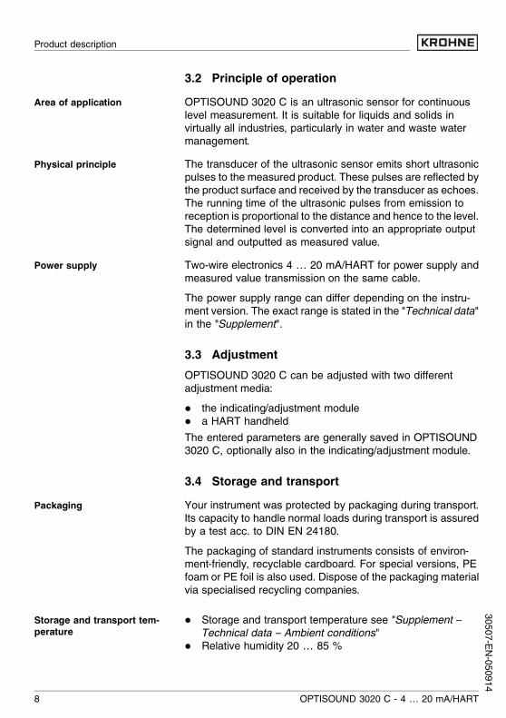
3.2 Principle of operationOPTISOUND 3020 C is an ultrasonic sensor for continuouslevel measurement. It is suitable for liquids and solids invirtually all industries, particularly in water and waste watermanagement.The transducer of the ultrasonic sensor emits short ultrasonicpulses to the measured product. These pulses are reflected bythe product surface and received by the transducer as echoes.The running time of the ultrasonic pulses from emission toreception is proportional to the distance and hence to the level.The determined level is converted into an appropriate outputsignal and outputted as measured value.Two-wire electronics 4 … 20 mA/HART for power supply andmeasured value transmission on the same cable.The power supply range can differ depending on the instru-ment version. The exact range is stated in the "Technical data"in the "Supplement".
3.3 AdjustmentOPTISOUND 3020 C can be adjusted with two differentadjustment media:l the indicating/adjustment modulel a HART handheldThe entered parameters are generally saved in OPTISOUND3020 C, optionally also in the indicating/adjustment module.
3.4 Storage and transportYour instrument was protected by packaging during transport.Its capacity to handle normal loads during transport is assuredby a test acc. to DIN EN 24180.The packaging of standard instruments consists of environ-ment-friendly, recyclable cardboard. For special versions, PEfoam or PE foil is also used. Dispose of the packaging materialvia specialised recycling companies.
l Storage and transport temperature see "Supplement –Technical data – Ambient conditions"
l Relative humidity 20 … 85 %
Area of application
Physical principle
Power supply
Packaging
Storage and transport tem-perature
8 OPTISOUND 3020 C - 4 … 20 mA/HART
Product description
30507-EN-050914
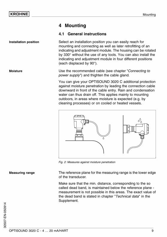
4 Mounting4.1 General instructionsSelect an installation position you can easily reach formounting and connecting as well as later retrofitting of anindicating and adjustment module. The housing can be rotatedby 330° without the use of any tools. You can also install theindicating and adjustment module in four different positions(each displaced by 90°).Use the recommended cable (see chapter "Connecting topower supply") and thighten the cable gland.You can give your OPTISOUND 3020 C additional protectionagainst moisture penetration by leading the connection cabledownward in front of the cable entry. Rain and condensationwater can thus drain off. This applies mainly to mountingoutdoors, in areas where moisture is expected (e.g. bycleaning processes) or on cooled or heated vessels.
Fig. 2: Measures against moisture penetration
The reference plane for the measuring range is the lower edgeof the transducer.Make sure that the min. distance, corresponding to the socalled dead band, is maintained below the reference plane -measurement is not possible in this areas. The exact value ofthe dead band is stated in chapter "Technical data" in theSupplement.
Installation position
Moisture
Measuring range
OPTISOUND 3020 C - 4 … 20 mA/HART 9
Mounting
3050
7-EN-
0509
14

12
Fig. 3: Min. distance to the max. level1 Dead zone2 Reference plane
Information:If the product reaches the transducer, buildup can form on itover a period of time and later cause measurement errors.
1 32
100%
0%
Fig. 4: Measuring range (operating range) and max. measuring distance1 full2 empty (max. measuring distance)3 Measuring range
Gauge pressure in the vessel does not influence OPTISOUND3020 C. Low pressure or vacuum, however, damp theultrasonic pulses. This influences the measuring result,particularly if the level is very low. With pressures under -0.2 bar (-20 kPa) you should use a different measuringprinciple, e.g. radar or guided radar (TDR).
Pressure/Vacuum
10 OPTISOUND 3020 C - 4 … 20 mA/HART
Mounting
30507-EN-050914

4.2 Mounting informationScrew OPTISOUND 3020 C into the mounting socket with anappropriate spanner applied to the hexagon of the processfitting. Max. torque see chapter "Technical data".
Warning:The housing must not be used to screw the instrument in!Applying tightening force to the housing can damage itsinternal mechanical components.
When mounting OPTISOUND 3020 C, keep a distance of atleast 200 mm (7.9 in) to the vessel wall. If the sensor isinstalled in the center of dished or rounded vessel tops,multiple echoes can arise. These can, however, be faded outby an appropriate adjustment (see chapter "Setup").If this distance cannot be maintained, a false echo storageshould be carried out during setup. This applies particularly ifbuildup on the vessel wall is expected. In this case, werecommend repeating the false echo storage later on withexisting buildup.
1
2
> 200 mm
Fig. 5: Mounting on dished vessel tops1 Reference plane2 Vessel center or symmetry axis
In vessels with conical bottom it can be advantageous tomount the sensor in the center of the vessel, as measurementis then possible down to the lowest point of the vessel bottom.
Screwing in
Installation position
OPTISOUND 3020 C - 4 … 20 mA/HART 11
Mounting
3050
7-EN-
0509
14

Fig. 6: Vessel with conical bottom
The mounting socket should preferably be dimensioned toallow the lower edge of the transducer to protrude at least 10mm out of the socket.
ca. 1
0 m
m
Fig. 7: Recommended socket mounting
If the reflective properties of the medium are good, you canmount OPTISOUND 3020 C on sockets higher than thetransducer length. You will find recommended values forsocket heights in the following illustration. The socket endshould be smooth and burr-free, if possible also rounded.Carry out a false echo storage.
Socket
12 OPTISOUND 3020 C - 4 … 20 mA/HART
Mounting
30507-EN-050914
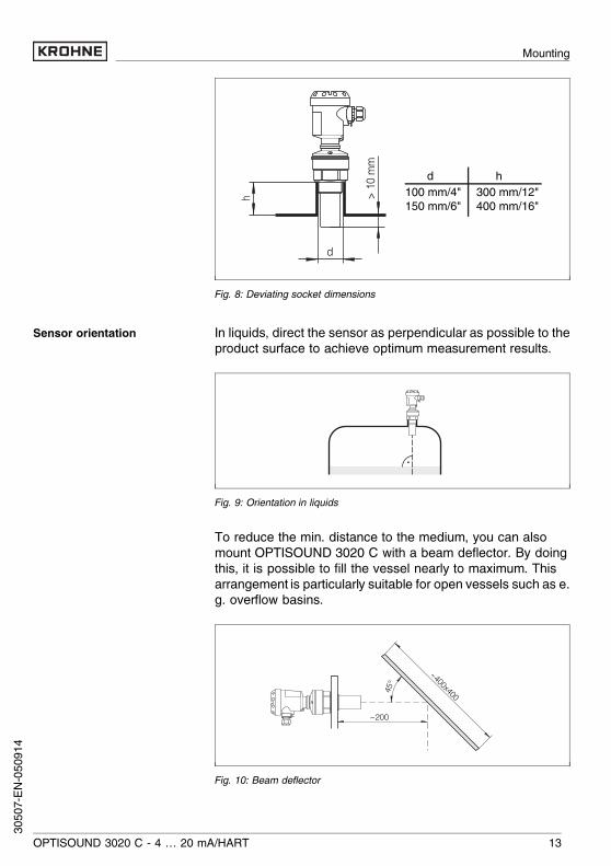
> 10
mm
dh
d h100 mm/4"150 mm/6"
300 mm/12"400 mm/16"
Fig. 8: Deviating socket dimensions
In liquids, direct the sensor as perpendicular as possible to theproduct surface to achieve optimum measurement results.
Fig. 9: Orientation in liquids
To reduce the min. distance to the medium, you can alsomount OPTISOUND 3020 C with a beam deflector. By doingthis, it is possible to fill the vessel nearly to maximum. Thisarrangement is particularly suitable for open vessels such as e.g. overflow basins.
~200
~400x40045°
Fig. 10: Beam deflector
Sensor orientation
OPTISOUND 3020 C - 4 … 20 mA/HART 13
Mounting
3050
7-EN-
0509
14
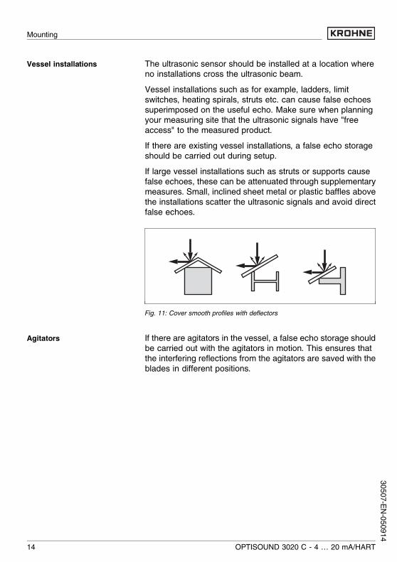
The ultrasonic sensor should be installed at a location whereno installations cross the ultrasonic beam.Vessel installations such as for example, ladders, limitswitches, heating spirals, struts etc. can cause false echoessuperimposed on the useful echo. Make sure when planningyour measuring site that the ultrasonic signals have "freeaccess" to the measured product.If there are existing vessel installations, a false echo storageshould be carried out during setup.If large vessel installations such as struts or supports causefalse echoes, these can be attenuated through supplementarymeasures. Small, inclined sheet metal or plastic baffles abovethe installations scatter the ultrasonic signals and avoid directfalse echoes.
Fig. 11: Cover smooth profiles with deflectors
If there are agitators in the vessel, a false echo storage shouldbe carried out with the agitators in motion. This ensures thatthe interfering reflections from the agitators are saved with theblades in different positions.
Vessel installations
Agitators
14 OPTISOUND 3020 C - 4 … 20 mA/HART
Mounting
30507-EN-050914

Fig. 12: Agitators
Do not mount the instruments in or above the filling stream.Make sure that you detect the product surface and not theinflowing product.
Fig. 13: Inflowing liquid
Through the action of filling, stirring and other processes in thevessel, dense foams which considerably damp the emittedsignals may form on the product surface.If foams are causing measurement errors, the sensor shouldbe used in a standpipe or, alternatively, the more suitableguided radar sensors (TDR) should be used.
Inflowing material
Foam
OPTISOUND 3020 C - 4 … 20 mA/HART 15
Mounting
3050
7-EN-
0509
14
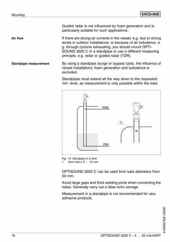
Guided radar is not influenced by foam generation and isparticularly suitable for such applications.If there are strong air currents in the vessel, e.g. due to strongwinds in outdoor installations, or because of air turbulence, e.g. through cyclone exhausting, you should mount OPTI-SOUND 3020 C in a standpipe or use a different measuringprinciple, e.g. radar or guided radar (TDR).By using a standpipe (surge or bypass tube), the influence ofvessel installations, foam generation and turbulence isexcluded.Standpipes must extend all the way down to the requestedmin. level, as measurement is only possible within the tube.
max.
min.
1
Fig. 14: Standpipe in a tank1 Vent hole ø 5 … 10 mm
OPTISOUND 3020 C can be used from tube diameters from50 mm.Avoid large gaps and thick welding joints when connecting thetubes. Generally carry out a false echo storage.Measurement in a standpipe is not recommended for veryadhesive products.
Air flow
Standpipe measurement
16 OPTISOUND 3020 C - 4 … 20 mA/HART
Mounting
30507-EN-050914
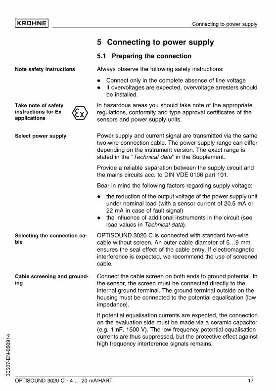
5 Connecting to power supply5.1 Preparing the connectionAlways observe the following safety instructions:l Connect only in the complete absence of line voltagel If overvoltages are expected, overvoltage arresters should
be installed.In hazardous areas you should take note of the appropriateregulations, conformity and type approval certificates of thesensors and power supply units.
Power supply and current signal are transmitted via the sametwo-wire connection cable. The power supply range can differdepending on the instrument version. The exact range isstated in the "Technical data" in the Supplement.Provide a reliable separation between the supply circuit andthe mains circuits acc. to DIN VDE 0106 part 101.Bear in mind the following factors regarding supply voltage:l the reduction of the output voltage of the power supply unit
under nominal load (with a sensor current of 20.5 mA or22 mA in case of fault signal)
l the influence of additional instruments in the circuit (seeload values in Technical data).
OPTISOUND 3020 C is connected with standard two-wirecable without screen. An outer cable diameter of 5…9 mmensures the seal effect of the cable entry. If electromagneticinterference is expected, we recommend the use of screenedcable.Connect the cable screen on both ends to ground potential. Inthe sensor, the screen must be connected directly to theinternal ground terminal. The ground terminal outside on thehousing must be connected to the potential equalisation (lowimpedance).If potential equalisation currents are expected, the connectionon the evaluation side must be made via a ceramic capacitor(e.g. 1 nF, 1500 V). The low frequency potential equalisationcurrents are thus suppressed, but the protective effect againsthigh frequency interference signals remains.
Note safety instructions
Take note of safetyinstructions for Exapplications
Select power supply
Selecting the connection ca-ble
Cable screening and ground-ing
OPTISOUND 3020 C - 4 … 20 mA/HART 17
Connecting to power supply
3050
7-EN-
0509
14
Take note of the corresponding installation regulations for Exapplications. In particular, make sure that no potential equal-isation currents flow over the cable screen. In case ofgrounding on both sides this can be achieved by the use of acapacitor or a separate potential equalisation.
5.2 Connection procedureProceed as follows:1 Unscrew the housing cover2 If an indicating and adjustment module is installed, remove
it by turning it slightly to the left.3 Loosen compression nut of the cable entry4 Remove approx. 10 cm (4 in) of the cable mantle, strip
approx. 1 cm (0.4 in) insulation from the ends of theindividual wires
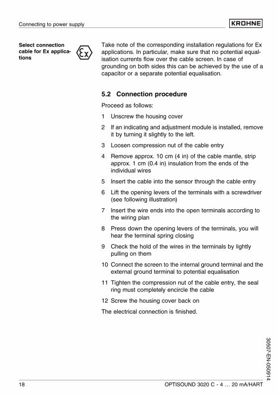
5 Insert the cable into the sensor through the cable entry6 Lift the opening levers of the terminals with a screwdriver
(see following illustration)7 Insert the wire ends into the open terminals according to
the wiring plan8 Press down the opening levers of the terminals, you will
hear the terminal spring closing9 Check the hold of the wires in the terminals by lightly
pulling on them10 Connect the screen to the internal ground terminal and the
external ground terminal to potential equalisation11 Tighten the compression nut of the cable entry, the seal
ring must completely encircle the cable12 Screw the housing cover back onThe electrical connection is finished.
Select connectioncable for Ex applica-tions
18 OPTISOUND 3020 C - 4 … 20 mA/HART
Connecting to power supply
30507-EN-050914
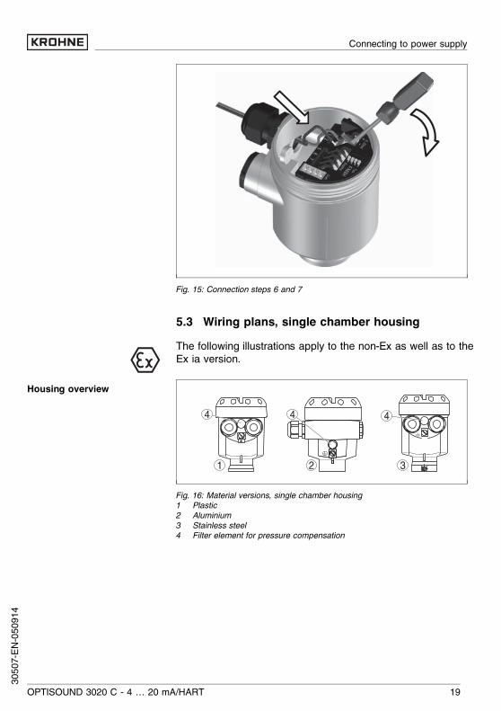
Fig. 15: Connection steps 6 and 7
5.3 Wiring plans, single chamber housingThe following illustrations apply to the non-Ex as well as to theEx ia version.
1
444
2 3
Fig. 16: Material versions, single chamber housing1 Plastic2 Aluminium3 Stainless steel4 Filter element for pressure compensation
Housing overview
OPTISOUND 3020 C - 4 … 20 mA/HART 19
Connecting to power supply
3050
7-EN-
0509
14

I2C
Display
1 2 5 6 7 8
2
1
Fig. 17: Electronics and connection compartment, single chamber housing1 Spring-loaded terminals for power supply2 Ground terminal for connection of the cable screen
I2C
Display
1
1 2 5 6 7 8
Fig. 18: Wiring plan, single chamber housing1 Power supply/Signal output
5.4 Wiring plans, double chamber housingThe following illustrations apply to the non-Ex as well as to theEEx ia version.
Electronics and connectioncompartment
Wiring plan
20 OPTISOUND 3020 C - 4 … 20 mA/HART
Connecting to power supply
30507-EN-050914
1 2 3
4 5
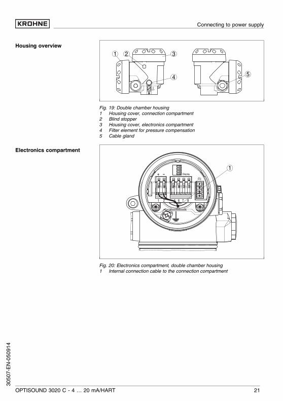
Fig. 19: Double chamber housing1 Housing cover, connection compartment2 Blind stopper3 Housing cover, electronics compartment4 Filter element for pressure compensation5 Cable gland
1Display
1 2 5 6 7 8
I2C
Fig. 20: Electronics compartment, double chamber housing1 Internal connection cable to the connection compartment
Housing overview
Electronics compartment
OPTISOUND 3020 C - 4 … 20 mA/HART 21
Connecting to power supply
3050
7-EN-
0509
14
1
2
Disp
lay
1 2 I2C
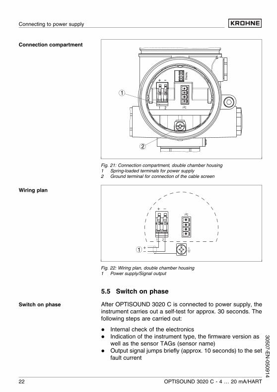
Fig. 21: Connection compartment, double chamber housing1 Spring-loaded terminals for power supply2 Ground terminal for connection of the cable screen
I2C
1
1 2
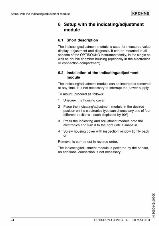
Fig. 22: Wiring plan, double chamber housing1 Power supply/Signal output
5.5 Switch on phaseAfter OPTISOUND 3020 C is connected to power supply, theinstrument carries out a self-test for approx. 30 seconds. Thefollowing steps are carried out:l Internal check of the electronicsl Indication of the instrument type, the firmware version as
well as the sensor TAGs (sensor name)l Output signal jumps briefly (approx. 10 seconds) to the set
fault current
Connection compartment
Wiring plan
Switch on phase
22 OPTISOUND 3020 C - 4 … 20 mA/HART
Connecting to power supply
30507-EN-050914

Then the actual measured value is displayed and thecorresponding current is transmitted to the cable.1)
1) The values correspond to the actual level as well as to the settings alreadycarried out, e.g. default setting.
OPTISOUND 3020 C - 4 … 20 mA/HART 23
Connecting to power supply
3050
7-EN-
0509
14
6 Setup with the indicating/adjustmentmodule
6.1 Short descriptionThe indicating/adjustment module is used for measured valuedisplay, adjustment and diagnosis. It can be mounted in allsensors of the OPTISOUND instrument family, in the single aswell as double chamber housing (optionally in the electronicsor connection compartment).
6.2 Installation of the indicating/adjustmentmodule
The indicating/adjustment module can be inserted or removedat any time. It is not necessary to interrupt the power supply.To mount, proceed as follows:1 Unscrew the housing cover2 Place the indicating/adjustment module in the desired
position on the electronics (you can choose any one of fourdifferent positions - each displaced by 90°)
3 Press the indicating and adjustment module onto theelectronics and turn it to the right until it snaps in.
4 Screw housing cover with inspection window tightly backon
Removal is carried out in reverse order.The indicating/adjustment module is powered by the sensor,an additional connection is not necessary.
24 OPTISOUND 3020 C - 4 … 20 mA/HART
Setup with the indicating/adjustment module
30507-EN-050914

Fig. 23: Installation of the indicating/adjustment moduleNote:If you intend to retrofit OPTISOUND 3020 C with an indicating/adjustment module for continuous measured value indication,a higher cover with an inspection glass is required.
OPTISOUND 3020 C - 4 … 20 mA/HART 25
Setup with the indicating/adjustment module
3050
7-EN-
0509
14

6.3 Adjustment system
1.1
2
3
1
Fig. 24: Indicating and adjustment elements1 LC display2 Indication of the menu item number3 Adjustment keys
l [OK] key:- move to the menu overview- confirm selected menu- edit parameter- save value
l [–>] key to select:- menu change- list entry- editing position
l [+] key:- modify value of a parameter
l [ESC] key:- interrupt input- jump to the next higher menu
The sensor is adjusted via the four keys of the indicating andadjustment module. The LC display indicates the individualmenu items. The functions of the individual keys are shown inthe above illustration. Approx. 10 minutes after the lastpressing of a key, an automatic reset to measured valueindication is triggered. Any values not confirmed with [OK] willnot be saved.
Key functions
Adjustment system
26 OPTISOUND 3020 C - 4 … 20 mA/HART
Setup with the indicating/adjustment module
30507-EN-050914
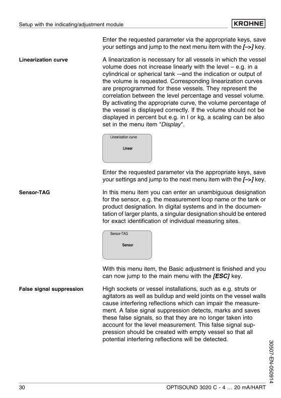
6.4 Setup procedureIn HART-Multidrop mode (several sensors on one input) theaddress must be set before continuing with the parameteradjustment. You will find a detailed description in the operatinginstructions manual of the indicating/adjustment module.
HART mode
StandardAddress 0
Because OPTISOUND 3020 C is a distance measuringinstrument, its primary task is to measure the distance from thesensor to the product surface. In order to indicate the actualfilling level, the measured distance must be allocated to aspecific height percentage. To make this adjustment, the fulland empty distances in the vessel are entered. If these valuesare not known, it is also possible to carry out the adjustmentwith other distances, e.g. 10 % and 90 %. The origin of thesedistance values is always the lower edge of the flange (withflange versions) or the lower edge of the transducer (all otherversions).The actual level is then calculated on the basis of theseentered values. At the same time, the operating range of thesensor is limited from maximum range to the requested range.The real product level during this adjustment is not important,because the min./max. adjustment is always carried outwithout changing the product level. These settings can bemade ahead of time without the instrument having to beinstalled.In the main menu item "Basic adjustment", the individualsubmenu items should be selected one after the other andprovided with the correct parameter values.Start your parameter adjustment with the following menu itemsof the basic adjustment:Proceed as follows:1 Move from the measured value display to the main menu
by pushing [OK].
Address setting HART-Multi-drop
Parameter adjustment
Carrying out min. adjustment
OPTISOUND 3020 C - 4 … 20 mA/HART 27
Setup with the indicating/adjustment module
3050
7-EN-
0509
14

▶ Basic adjustmentDisplayDiagnosticsServiceInfo
2 Select the menu item "Basic adjustment" with [–>] andconfirm with [OK]. Now the menu item "Min. adjustment" isdisplayed.
Min. adjustment0.00 %=5.000 m(d)
4.000 m(d)
3 Prepare the % value for editing with [OK] and set thecursor to the requested position with [–>]. Set therequested percentage value with [+] and save with [OK].The cursor jumps now to the distance value.
4 Enter the appropriate distance value in m (correspondingto the percentage value) for the empty vessel (e.g. distancefrom the sensor to the vessel bottom).
5 Save the settings with [OK] and move to "Max. adjustment"with [–>].
Proceed as follows:Max. adjustment100.00 %=1.000 m(d)
2.000 m(d)
1 Prepare the % value for editing with [OK] and set thecursor to the requested position with [–>]. Set therequested percentage value with [+] and save with [OK].The cursor jumps now to the distance value.
2 Enter the appropriate distance value in m (correspondingto the percentage value) for the full vessel. Keep in mindthat the max. level must lie below the dead band.
3 Save the settings with [OK] and move to "Mediumselection" with [–>].
Each product has different reflective properties. In addition,there are various interfering factors which have to be taken intoaccount: agitated product surfaces and foam generation (withliquids); dust generation, material cones and echoes from the
Carrying out max. adjustment
Medium selection
28 OPTISOUND 3020 C - 4 … 20 mA/HART
Setup with the indicating/adjustment module
30507-EN-050914

vessel wall (with solids). To adapt the sensor to these differentconditions, you should first select in this menu item "Liquid" or"Solid".
MediumLiquid
With solids, you can also choose between "Powder/Dust","Granular/Pellets" or "Ballast/Pebbels".Through this additional selection, the sensor is adaptedperfectly to the product and measurement reliability, partic-ularly in products with bad reflective properties, is considerablyincreased.Enter the requested parameter via the appropriate keys, saveyour settings and jump to the next menu item with the [–>] key.Apart from the medium also the vessel form can influence themeasurement. To adapt the sensor to these conditions, thismenu item offers (depending on either liquid or solid isdetected) different options. For Liquid these are Storage tank,Stilling tube, Open vessel or Stirred vessel, for Solid Silo orBunker.
Vessel shape
Storage tank
Enter the requested parameter via the appropriate keys, saveyour settings and jump to the next menu item with the [–>] key.To suppress fluctuation in the measured value display, e.g.caused by a turbulent product surface, an integration time canbe set. This time can be between 0 and 999 seconds. Pleasenote that the reaction time of the entire measurement will belonger and the sensor will react to quick changes of themeasured value with a corresponding delay. In general, a timeof a few seconds is sufficient to smooth the measured valuedisplay.
Damping
0 s
Vessel shape
Damping
OPTISOUND 3020 C - 4 … 20 mA/HART 29
Setup with the indicating/adjustment module
3050
7-EN-
0509
14
Enter the requested parameter via the appropriate keys, saveyour settings and jump to the next menu item with the [–>] key.A linearization is necessary for all vessels in which the vesselvolume does not increase linearly with the level – e.g. in acylindrical or spherical tank -–and the indication or output ofthe volume is requested. Corresponding linearization curvesare preprogrammed for these vessels. They represent thecorrelation between the level percentage and vessel volume.By activating the appropriate curve, the volume percentage ofthe vessel is displayed correctly. If the volume should not bedisplayed in percent but e.g. in l or kg, a scaling can be alsoset in the menu item "Display".
Linearization curve
Linear
Enter the requested parameter via the appropriate keys, saveyour settings and jump to the next menu item with the [–>] key.In this menu item you can enter an unambiguous designationfor the sensor, e.g. the measurement loop name or the tank orproduct designation. In digital systems and in the documen-tation of larger plants, a singular designation should be enteredfor exact identification of individual measuring sites.
Sensor-TAG
Sensor
With this menu item, the Basic adjustment is finished and youcan now jump to the main menu with the [ESC] key.High sockets or vessel installations, such as e.g. struts oragitators as well as buildup and weld joints on the vessel wallscause interfering reflections which can impair the measure-ment. A false signal suppression detects, marks and savesthese false signals, so that they are no longer taken intoaccount for the level measurement. This false signal sup-pression should be created with empty vessel so that allpotential interfering reflections will be detected.
Linearization curve
Sensor-TAG
False signal suppression
30 OPTISOUND 3020 C - 4 … 20 mA/HART
Setup with the indicating/adjustment module
30507-EN-050914
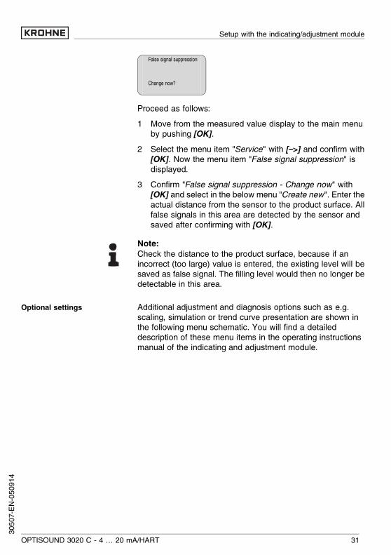
False signal suppression
Change now?
Proceed as follows:1 Move from the measured value display to the main menu
by pushing [OK].2 Select the menu item "Service" with [–>] and confirm with
[OK]. Now the menu item "False signal suppression" isdisplayed.
3 Confirm "False signal suppression - Change now" with[OK] and select in the below menu "Create new". Enter theactual distance from the sensor to the product surface. Allfalse signals in this area are detected by the sensor andsaved after confirming with [OK].
Note:Check the distance to the product surface, because if anincorrect (too large) value is entered, the existing level will besaved as false signal. The filling level would then no longer bedetectable in this area.
Additional adjustment and diagnosis options such as e.g.scaling, simulation or trend curve presentation are shown inthe following menu schematic. You will find a detaileddescription of these menu items in the operating instructionsmanual of the indicating and adjustment module.
Optional settings
OPTISOUND 3020 C - 4 … 20 mA/HART 31
Setup with the indicating/adjustment module
3050
7-EN-
0509
14
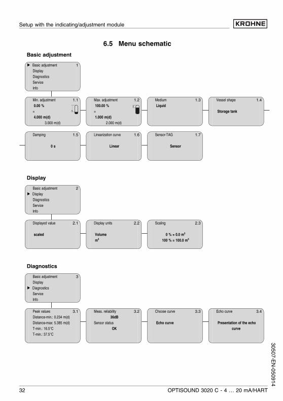
6.5 Menu schematicBasic adjustment
1▶ Basic adjustmentDisplayDiagnosticsServiceInfo
1.1Min. adjustment0.00 %=4.000 m(d)
3.000 m(d)
1.2Max. adjustment100.00 %=1.000 m(d)
2.000 m(d)
1.3MediumLiquid
1.4Vessel shape
Storage tank
1.5Damping
0 s
1.6Linearization curve
Linear
1.7Sensor-TAG
Sensor
Display2Basic adjustment
▶ DisplayDiagnosticsServiceInfo
2.1Displayed value
scaled
2.2Display units
Volumem³
2.3Scaling
0 % = 0.0 m³100 % = 100.0 m³
Diagnostics3Basic adjustment
Display▶ Diagnostics
ServiceInfo
3.1Peak valuesDistance-min.: 0.234 m(d)Distance-max: 5.385 m(d)T-min.: 16.5°CT-min.: 37.5°C
3.2Meas. reliability36dB
Sensor statusOK
3.3Choose curve
Echo curve
3.4Echo curve
Presentation of the echocurve
32 OPTISOUND 3020 C - 4 … 20 mA/HART
Setup with the indicating/adjustment module
30507-EN-050914
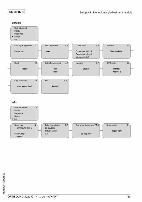
Service4Basic adjustment
DisplayDiagnostics
▶ ServiceInfo
4.1False signal suppression
Change now?
4.2Addl. adjustments
none
4.3Current output
Output mode 4-20 mAFailure mode: <3.6mAMin-current 3.8mA
4.4Simulation
Start simulation?
4.5Reset
Reset?
4.6Units of measurement
m(d)select?
4.7Language
Deutsch
4.8HART mode
StandardAddress 0
4.9Copy sensor data
Copy sensor data?
4.10PIN
Enable?
Info5Basic adjustment
DisplayDiagnosticsService
▶ Info
5.1Sensor typeOPTISOUND 30x0 C
Serial number12345678
5.2Date of manufacture26. July 2005Software version3.26
5.3Date of last change using PC
26. July 2005
5.4Sensor details
Display now?
OPTISOUND 3020 C - 4 … 20 mA/HART 33
Setup with the indicating/adjustment module
3050
7-EN-
0509
14
7 Maintenance and fault rectification7.1 MaintenanceWhen used as directed in normal operation, OPTISOUND3020 C is completely maintenance-free.
7.2 Fault rectificationOPTISOUND 3020 C offers maximum reliability. Neverthelessfaults can occur during operation. These may be caused by thefollowing, e.g.:l Sensorl Processl Power supplyl Signal processing.The first measures to be taken are to check the output signaland evaluate fault messages via the indicating/adjustmentmodule. The procedure is described below.Connect a hand-held multimeter with a suitable measuringrange acc. to the wiring plan.? 4 … 20 mA signal not stable
l level fluctuationsà set integration time via the indicating/adjustment
module
? 4 … 20 mA signal missingl incorrect connection to power supplyà Check connection acc. to chapter "Connection proce-
dure" and correct, if necessary, acc. to chapter "Wiringplans"
l no power supplyà check cables for line break, repair, if necessaryl supply voltage too low or load resistance too highà check and adapt, if necessary
Causes of malfunction
Fault rectification
Checking the 4 … 20 mA sig-nal
34 OPTISOUND 3020 C - 4 … 20 mA/HART
Maintenance and fault rectification
30507-EN-050914
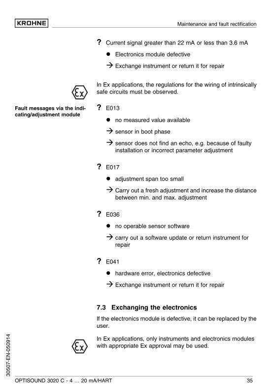
? Current signal greater than 22 mA or less than 3.6 mAl Electronics module defectiveà Exchange instrument or return it for repair
In Ex applications, the regulations for the wiring of intrinsicallysafe circuits must be observed.
? E013l no measured value availableà sensor in boot phaseà sensor does not find an echo, e.g. because of faulty
installation or incorrect parameter adjustment
? E017l adjustment span too smallà Carry out a fresh adjustment and increase the distance
between min. and max. adjustment
? E036l no operable sensor softwareà carry out a software update or return instrument for
repair
? E041l hardware error, electronics defectiveà Exchange instrument or return it for repair
7.3 Exchanging the electronicsIf the electronics module is defective, it can be replaced by theuser.In Ex applications, only instruments and electronics moduleswith appropriate Ex approval may be used.
Fault messages via the indi-cating/adjustment module
OPTISOUND 3020 C - 4 … 20 mA/HART 35
Maintenance and fault rectification
3050
7-EN-
0509
14
If there is no electronics module available on site, it can beordered from the responsible Krohne agency.
7.4 Instrument repairIf a repair is necessary, please proceed as follows:You can download a return form from our Internet homepagehttp://www.krohne-mar.com/fileadmin/media-lounge/PDF-Download/Specimen_e.pdf.By doing this you help us carry out the repair quickly andwithout having to call back for needed information.l Print and fill out one form per instrumentl Clean the instrument and pack it damage-proofl Attach the completed form and possibly also a safety data
sheet to the instrument.
36 OPTISOUND 3020 C - 4 … 20 mA/HART
Maintenance and fault rectification
30507-EN-050914

8 Dismounting8.1 Dismounting procedureWarning:Before dismounting, be aware of dangerous process con-ditions such as e.g. pressure in the vessel, high temperatures,corrosive or toxic products etc.
Take note of chapters "Mounting" and "Connecting to powersupply" and carry out the listed steps in reverse order.
8.2 DisposalOPTISOUND 3020 C consists of materials which can berecycled by specialised recycling companies. We havepurposely designed the electronic modules to be easilyseparable. Mark the instrument as scrap and dispose of itaccording to national government regulations (e.g. in Germanyacc. to the EU Directive on Waste Electrical and ElectronicEquipment, WEEE).Materials: see "Technical data"If you cannot dispose of the instrument properly, pleasecontact us about disposal methods or return.
OPTISOUND 3020 C - 4 … 20 mA/HART 37
Dismounting
3050
7-EN-
0509
14

9 Supplement9.1 Technical dataGeneral dataMaterials, wetted parts- Process fitting thread G2A and 2 NPT: PVDF- Transducer PVDF- seal transducer/thread EPDMMaterials, non-wetted parts- Housing plastic PBT (Polyester), Alu-die casting pow-
der-coated, 316L (1.4435)- Seal ring between housing and
housing coverNBR (stainless steel housing), silicone (Alu/plastic housing)
- Inspection window in housing cover Polycarbonate- Ground terminal 316Ti/316L (1.4571/1.4435)Weight 1.8 … 4.0 kg (4.0 … 8.8 lbs), depending on
process fitting and housingMax. torque mounting boss 25 Nm
Output variableOutput signal 4 … 20 mA/HARTResolution 1.6 µAFault signal current output unchanged; 20.5 mA; 22 mA;
<3.6 mA (adjustable)Current limitation 22 mALoad see load diagram in Power supplyIntegration time (63 % of the inputvariable)
0 … 999 s, adjustable
Fulfilled NAMUR recommendation NE 43
Input variableParameter distance between lower edge of the transducer
and product surfaceDead zone 0.4 m (1.3 ft)Measuring range- Liquids up to 8 m (26.2 ft)- Solid up to 3.5 m (11.5 ft)
38 OPTISOUND 3020 C - 4 … 20 mA/HART
Supplement
30507-EN-050914
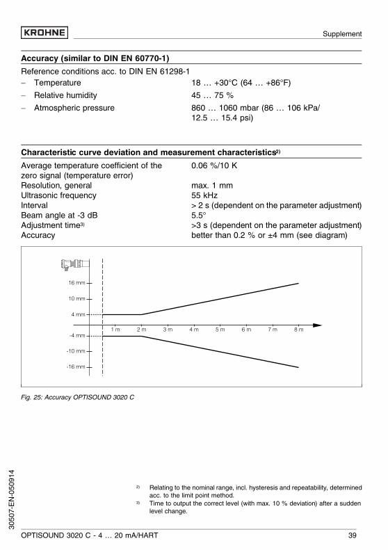
Accuracy (similar to DIN EN 60770-1)Reference conditions acc. to DIN EN 61298-1- Temperature 18 … +30°C (64 … +86°F)- Relative humidity 45 … 75 %- Atmospheric pressure 860 … 1060 mbar (86 … 106 kPa/
12.5 … 15.4 psi)
Characteristic curve deviation and measurement characteristics2)Average temperature coefficient of thezero signal (temperature error)
0.06 %/10 K
Resolution, general max. 1 mmUltrasonic frequency 55 kHzInterval > 2 s (dependent on the parameter adjustment)Beam angle at -3 dB 5.5°Adjustment time3) >3 s (dependent on the parameter adjustment)Accuracy better than 0.2 % or ±4 mm (see diagram)
8 m4 m3 m2 m 7 m6 m5 m1 m
10 mm
16 mm
4 mm
-4 mm
-10 mm
-16 mm
Fig. 25: Accuracy OPTISOUND 3020 C
2) Relating to the nominal range, incl. hysteresis and repeatability, determinedacc. to the limit point method.
3) Time to output the correct level (with max. 10 % deviation) after a suddenlevel change.
OPTISOUND 3020 C - 4 … 20 mA/HART 39
Supplement
3050
7-EN-
0509
14

Ambient conditionsAmbient, storage and transport temperature- without indicating/adjustment mod-
ule-40 … +80°C (-40 … +176°F)
- the indicating/adjustment module -20 … +70°C (-4 … +158°F)
Process conditionsVessel pressure -20 … 200 kPa (-0.2 … 2.0 bar/-2.9 … 29 psi)Process temperature (transducer tem-perature)
-40 … +80°C (-40 … +176°F)
Vibration resistance mechanical vibrations with 4 g and 5… 100Hz4)
Electromechanical dataCable entry- Single chamber housing l 1x cable entryM20x1.5 (cable-ø 5… 9mm),
1x blind stopper M20x1.5or:l 1x closing cap ½ NPT, 1x blind stopper
½ NPT- Double chamber housing l 1x cable entryM20x1.5 (cable-ø 5… 9mm),
1x blind stopper M20x1.5or:l 1x closing cap ½ NPT, 1x blind stopper
½ NPTSpring-loaded terminals for wire cross sections up to 2.5 mm²
Indicating and adjustment modulePower supply and data transmission through sensor via gold-plated sliding contacts
(I²C bus)Indication LC display in full dot matrixAdjustment elements 4 keysProtection- unassembled IP 20- mounted into the sensor without
coverIP 40
Materials- Housing ABS- Inspection window Polyester foil
4) Tested acc. to the regulations of German Lloyd, GL directive 2
40 OPTISOUND 3020 C - 4 … 20 mA/HART
Supplement
30507-EN-050914
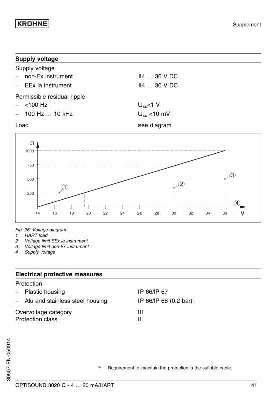
Supply voltageSupply voltage- non-Ex instrument 14 … 36 V DC- EEx ia instrument 14 … 30 V DCPermissible residual ripple- <100 Hz Uss<1 V- 100 Hz … 10 kHz Uss <10 mVLoad see diagram
1000
750
500
250
14 1816 20 22 24 26 28 30 32 34 36
Ω
V
4
1 2
3
Fig. 26: Voltage diagram1 HART load2 Voltage limit EEx ia instrument3 Voltage limit non-Ex instrument4 Supply voltage
Electrical protective measuresProtection- Plastic housing IP 66/IP 67- Alu and stainless steel housing IP 66/IP 68 (0.2 bar)5)Overvoltage category IIIProtection class II
5) Requirement to maintain the protection is the suitable cable.
OPTISOUND 3020 C - 4 … 20 mA/HART 41
Supplement
3050
7-EN-
0509
14
Approvals6)7)
ATEX ATEX II 1G, 1/2G, 2G EEx ia IIC T6
6) Deviating data with Ex applications: see separate safety instructions.7) Depending on order specification.
42 OPTISOUND 3020 C - 4 … 20 mA/HART
Supplement
30507-EN-050914
9.2 Dimensions
Housing11
2mm
(4 1
3 /32
")
117m
m(4
39 /
64")
114m
m(4
31 /
64")
~ 69mm(2 23/32") ø 77mm
(3 1/32")
~ 69mm(2 23/32")
~ 116mm(4 9/16")ø 77mm
(3 1/32")ø 84mm(3 5/16")
120m
m (
4 23
/ 32"
)
~ 87mm (3 27/64")ø 84mm(3 5/16")
M20x1,5M20x1,5/½ NPT
M20x1,5/½ NPT
M20x1,5/½ NPT
1 2 3 4M20x1,5/½ NPT
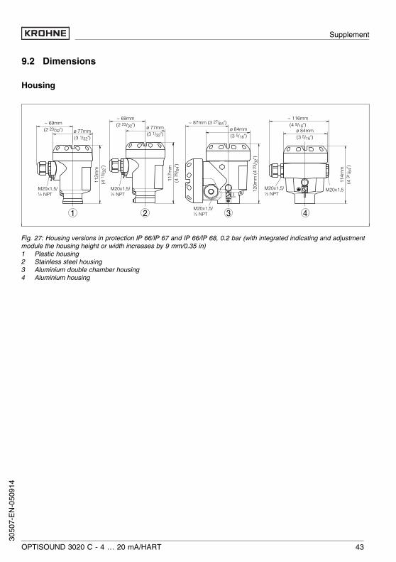
Fig. 27: Housing versions in protection IP 66/IP 67 and IP 66/IP 68, 0.2 bar (with integrated indicating and adjustmentmodule the housing height or width increases by 9 mm/0.35 in)1 Plastic housing2 Stainless steel housing3 Aluminium double chamber housing4 Aluminium housing
OPTISOUND 3020 C - 4 … 20 mA/HART 43
Supplement
3050
7-EN-
0509
14

OPTISOUND 3020 C
1 2
153m
m (6
1 /32
")
20m
m (2
5 /32
")63
mm
(2 31
/ 64"
)
ø 50mm(1 31/32")ø 74mm(2 58/64")
60mm(2 23/64")
G2A /2"NPT
Fig. 28: OPTISOUND 3020 C1 Dead zone: 0.4 m (1.3 ft)2 Meas. range: in liquids up to 8 m (26.2 ft), in solids up to 3,5 m (11.5 ft)
44 OPTISOUND 3020 C - 4 … 20 mA/HART
Supplement
30507-EN-050914
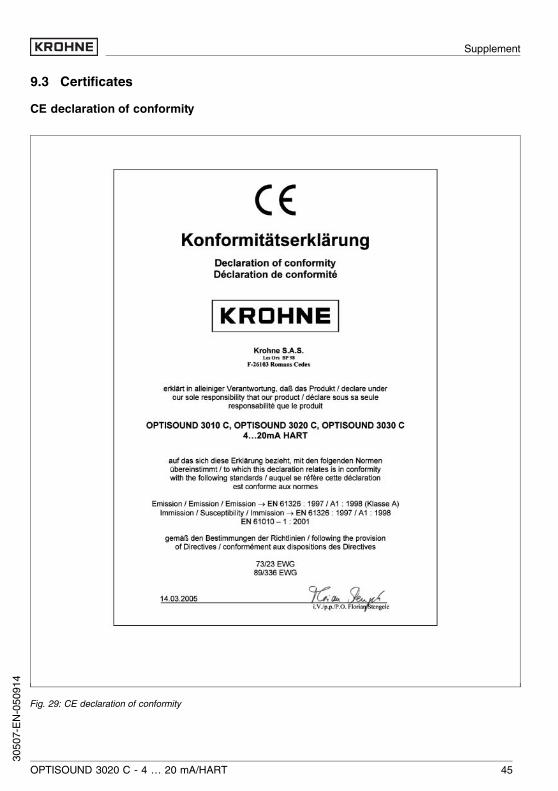
9.3 CertificatesCE declaration of conformity
Fig. 29: CE declaration of conformity
OPTISOUND 3020 C - 4 … 20 mA/HART 45
Supplement
3050
7-EN-
0509
14

Manufacturer declaration
Fig. 30: Manufacturer declaration
46 OPTISOUND 3020 C - 4 … 20 mA/HART
Supplement
30507-EN-050914
OPTISOUND 3020 C - 4 … 20 mA/HART 47
Supplement
3050
7-EN-
0509
14

Subject to change without notice
30507-EN-050914