Embed Size (px)
Citation preview

Operating instruction manual OI/MT5100-EN Rev. B 05.2012
MT5100 Guided Wave Radar Level Transmitter
Introduction This operating instruction manual provides the following information: - Recommended installation practices—see page 8 - Commissioning details—see page 16 - Maintenance and troubleshooting—37 - Installation drawings—see page 39
State-of-the-art loop powered, 4-20 mA output guided wave radar for level and interface applications K-TEK Products
2
TABLE OF CONTENTS 1. Introduction ............................................................................................................................................................ 4 2. Overview ................................................................................................................................................................ 5 2.1 Storage and Handling Information ................................................................................................................. 5 2.2 Ambient Temperature .................................................................................................................................... 5 2.3 Description and Principle of Operation .......................................................................................................... 6 2.4 Total Level and Interface Level Measurement .............................................................................................. 7 3. Installation .............................................................................................................................................................. 8 3.1 Special Requirements ................................................................................................................................... 8 3.2 Mechanical Installation .................................................................................................................................. 9 3.2.1 Shortening of the Probe ..................................................................................................................... 9 3.2.2 Plastic Tanks, Fiberglass Tanks, and Open Air Installations ............................................................. 9 3.2.3 Single Probes in Stilling Wells ............................................................................................................ 10 3.2.4 Single Probes in External Chambers ................................................................................................. 12 3.2.5 Dual Rod/Cable Probes ...................................................................................................................... 13 3.2.6 Coaxial Probes ................................................................................................................................... 13 3.2.7 Unmeasurable Zones ......................................................................................................................... 14 3.3 Shortening of Probes ..................................................................................................................................... 15 3.4 Electrical Installation ...................................................................................................................................... 15 4. Commissioning ....................................................................................................................................................... 16 4.1 Display Operation .......................................................................................................................................... 16 4.1.1 Jumper Settings ................................................................................................................................. 17 4.1.2 Push Buttons ...................................................................................................................................... 17 4.2 MT5100 Menu Flow Chart ............................................................................................................................. 18 4.3 Basic Setup ................................................................................................................................................... 19 4.3.1 Units ................................................................................................................................................... 19 4.3.2 Probe Type ......................................................................................................................................... 19 4.3.3 Probe Length ...................................................................................................................................... 20 4.3.4 Offsets ................................................................................................................................................ 21 4.3.5 Upper Dielectric .................................................................................................................................. 22 4.3.6 Actual Interface .................................................................................................................................. 22 4.3.7 Lower Dielectric (Optional) ................................................................................................................. 22 4.3.8 Language ............................................................................................................................................ 23 4.4 Quick Calibration ........................................................................................................................................... 23 4.5 mA Output Setup ........................................................................................................................................... 24 4.5.1 Output ................................................................................................................................................. 24 4.5.2 LRV 4mA ............................................................................................................................................ 24 4.5.3 URV 20mA .......................................................................................................................................... 25 4.5.4 Dampening ......................................................................................................................................... 25 4.5.5 Alarm Delay ........................................................................................................................................ 26 4.5.6 DAC Trim ............................................................................................................................................ 26 4.5.7 LOOP Test .......................................................................................................................................... 26 4.5.8 HART Address.................................................................................................................................... 27 4.6 Extended Setup ............................................................................................................................................. 27 4.6.1 Waveform Display .............................................................................................................................. 28 4.6.2 Functions ............................................................................................................................................ 30 4.6.3 Temperature ....................................................................................................................................... 31 4.6.4 Flooded Chamber ............................................................................................................................... 31 4.6.5 Flooded Total...................................................................................................................................... 31 4.6.6 Linearization Menu ............................................................................................................................. 32 4.6.6.1 Linearization for Measurement ............................................................................................. 33 4.6.6.2 Linearization for Volume ...................................................................................................... 34 4.6.6.3 Linearization for Flow ........................................................................................................... 35 4.6.6.4 User Functions ..................................................................................................................... 36 4.7 Secondary Output - RI100 Option ................................................................................................................. 36
3
5. Troubleshooting ..................................................................................................................................................... 37 5.1 Valid Current Loop Outputs ........................................................................................................................... 37 5.2 Symptoms and Solutions ............................................................................................................................... 38
5.3 Electronics Module Replacement .................................................................................................................. 38 6. Installation Drawings for Intrinsic Safety & Standard Wiring ................................................................................. 39 7. Loop Powered TX Hookup / RI Dual Compartment Housing ................................................................................ 42 8. CE Certificate of Compliance ................................................................................................................................ 43 9. Customer Support ................................................................................................................................................. 44 9.1 RMA Form ...................................................................................................................................................... 45 10. Warranty Statement .............................................................................................................................................. 46
4
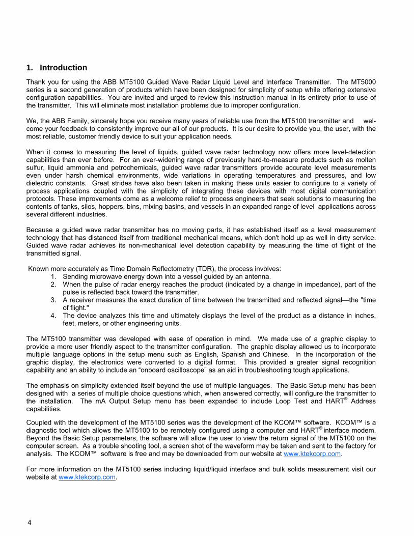
Thank you for using the ABB MT5100 Guided Wave Radar Liquid Level and Interface Transmitter. The MT5000 series is a second generation of products which have been designed for simplicity of setup while offering extensive configuration capabilities. You are invited and urged to review this instruction manual in its entirety prior to use of the transmitter. This will eliminate most installation problems due to improper configuration. We, the ABB Family, sincerely hope you receive many years of reliable use from the MT5100 transmitter and wel-come your feedback to consistently improve our all of our products. It is our desire to provide you, the user, with the most reliable, customer friendly device to suit your application needs. When it comes to measuring the level of liquids, guided wave radar technology now offers more level-detection capabilities than ever before. For an ever-widening range of previously hard-to-measure products such as molten sulfur, liquid ammonia and petrochemicals, guided wave radar transmitters provide accurate level measurements even under harsh chemical environments, wide variations in operating temperatures and pressures, and low dielectric constants. Great strides have also been taken in making these units easier to configure to a variety of process applications coupled with the simplicity of integrating these devices with most digital communication protocols. These improvements come as a welcome relief to process engineers that seek solutions to measuring the contents of tanks, silos, hoppers, bins, mixing basins, and vessels in an expanded range of level applications across several different industries. Because a guided wave radar transmitter has no moving parts, it has established itself as a level measurement technology that has distanced itself from traditional mechanical means, which don't hold up as well in dirty service. Guided wave radar achieves its non-mechanical level detection capability by measuring the time of flight of the transmitted signal. Known more accurately as Time Domain Reflectometry (TDR), the process involves:
1. Sending microwave energy down into a vessel guided by an antenna. 2. When the pulse of radar energy reaches the product (indicated by a change in impedance), part of the
pulse is reflected back toward the transmitter. 3. A receiver measures the exact duration of time between the transmitted and reflected signal—the "time
of flight." 4. The device analyzes this time and ultimately displays the level of the product as a distance in inches,
feet, meters, or other engineering units. The MT5100 transmitter was developed with ease of operation in mind. We made use of a graphic display to provide a more user friendly aspect to the transmitter configuration. The graphic display allowed us to incorporate multiple language options in the setup menu such as English, Spanish and Chinese. In the incorporation of the graphic display, the electronics were converted to a digital format. This provided a greater signal recognition capability and an ability to include an “onboard oscilloscope” as an aid in troubleshooting tough applications. The emphasis on simplicity extended itself beyond the use of multiple languages. The Basic Setup menu has been designed with a series of multiple choice questions which, when answered correctly, will configure the transmitter to the installation. The mA Output Setup menu has been expanded to include Loop Test and HART® Address capabilities. Coupled with the development of the MT5100 series was the development of the KCOM™ software. KCOM™ is a diagnostic tool which allows the MT5100 to be remotely configured using a computer and HART® interface modem. Beyond the Basic Setup parameters, the software will allow the user to view the return signal of the MT5100 on the computer screen. As a trouble shooting tool, a screen shot of the waveform may be taken and sent to the factory for analysis. The KCOM™ software is free and may be downloaded from our website at www.ktekcorp.com. For more information on the MT5100 series including liquid/liquid interface and bulk solids measurement visit our website at www.ktekcorp.com.
1. Introduction
5
2. Overview
2.1 Storage and Handling Information If possible, storage prior to installation should be indoors at ambient temperature, not to exceed the following: Temperature range: -40 to 150 degrees F. Humidity: 0 to 100% R.H. non-condensing. To avoid probe damage: Do not transport or support the weight of the MT5100 by means of the probe. Installation of rigid probes and flange mounted transmitters may require the use of lifting equipment. Avoid sharp bending of cable probes which can result in poor instrument operation. The lids on the MT5100 housing are sealed with o-rings. To avoid damage to the electronics, both lids should be closed tightly before and after installation. 2.2 Ambient Temperature The MT5100 electronics temperature may not exceed 170°F / 77°C. For higher ambient temperatures due to radiant process heat, a high temperature extension option is required. The coupler process temperature shall not exceed the temperature stated in the datasheet specifications for the given coupler.
6
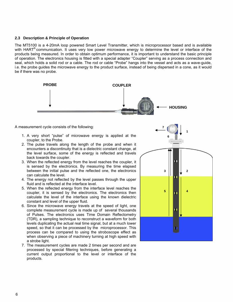
The MT5100 is a 4-20mA loop powered Smart Level Transmitter, which is microprocessor based and is available with HART® communication. It uses very low power microwave energy to determine the level or interface of the products being measured. In order to obtain optimum performance, it is important to understand the basic principle of operation. The electronics housing is fitted with a special adapter “Coupler” serving as a process connection and seal, which holds a solid rod or a cable. The rod or cable “Probe” hangs into the vessel and acts as a wave-guide, i.e. the probe guides the microwave energy to the product surface, instead of being dispersed in a cone, as it would be if there was no probe.
A measurement cycle consists of the following:
1. A very short “pulse” of microwave energy is applied at the coupler, to the Probe.
2. The pulse travels along the length of the probe and when it encounters a discontinuity that is a dielectric constant change, at the level surface, some of the energy is reflected and travels back towards the coupler.
3. When the reflected energy from the level reaches the coupler, it is sensed by the electronics. By measuring the time elapsed between the initial pulse and the reflected one, the electronics can calculate the level.
4. The energy not reflected by the level passes through the upper fluid and is reflected at the interface level.
5. When the reflected energy from the interface level reaches the coupler, it is sensed by the electronics. The electronics then calculate the level of the interface using the known dielectric constant and level of the upper fluid.
6. Since the microwave energy travels at the speed of light, one complete measurement cycle is made up of several thousands of Pulses. The electronics uses Time Domain Reflectometry (TDR), a sampling technique to reconstruct a waveform for both levels duplicating the actual real time signal, but at a much lower speed, so that it can be processed by the microprocessor. This process can be compared to using the stroboscope effect as when observing a piece of machinery turning at high speed with a strobe light.
7. The measurement cycles are made 2 times per second and are processed by special filtering techniques, before generating a current output proportional to the level or interface of the products.
2.3 Description & Principle of Operation
PROBE COUPLER
HOUSING
1
2
4
7
6
3
5
7
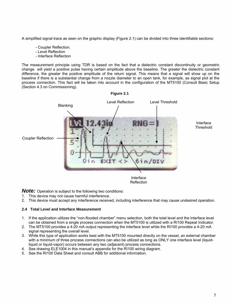
A simplified signal trace as seen on the graphic display (Figure 2.1) can be divided into three identifiable sections:
- Coupler Reflection. - Level Reflection - Interface Reflection
The measurement principle using TDR is based on the fact that a dielectric constant discontinuity or geometric change will yield a positive pulse having certain amplitude above the baseline. The greater the dielectric constant difference, the greater the positive amplitude of the return signal. This means that a signal will show up on the baseline if there is a substantial change from a nozzle diameter to an open tank, for example, as signal plot at the process connection. This fact will be taken into account in the configuration of the MT5100 (Consult Basic Setup (Section 4.3 on Commissioning).
Figure 2.1
Coupler Reflection
Level Reflection Blanking
Level Threshold
Interface Reflection
Interface Threshold
Note: Operation is subject to the following two conditions: 1. This device may not cause harmful interference. 2. This device must accept any interference received, including interference that may cause undesired operation. 2.4 Total Level and Interface Measurement 1. If the application utilizes the “non-flooded chamber” menu selection, both the total level and the interface level
can be obtained from a single process connection when the MT5100 is utilized with a RI100 Repeat Indicator. 2. The MT5100 provides a 4-20 mA output representing the interface level while the RI100 provides a 4-20 mA
signal representing the overall level. 3. While this type of application works best with the MT5100 mounted directly on the vessel, an external chamber
with a minimum of three process connections can also be utilized as long as ONLY one interface level (liquid-liquid or liquid-vapor) occurs between any two (adjacent) process connections.
4. See drawing ELE1004 in this manual’s appendix for the RI100 wiring diagram. 5. See the RI100 Data Sheet and consult ABB for additional information.
8
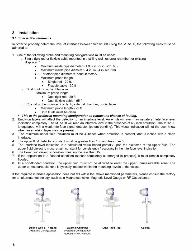
In order to properly detect the level of interface between two liquids using the MT5100, the following rules must be adhered to: 1. One of the following probe and mounting configurations must be used:
a. Single rigid rod or flexible cable mounted in a stilling well, external chamber, or existing displacer.*
Minimum inside pipe diameter - 1.939 in. (2 in. sch. 80) Maximum inside pipe diameter - 4.26 in. (4 in sch. 10) For other pipe diameters, consult factory. Maximum probe length:
Single rod - 20 ft. Flexible cable - 30 ft
b. Dual rigid rod or flexible cable Maximum probe length
Dual rigid rod - 20 ft Dual flexible cable - 65 ft
c. Coaxial probe mounted into tank, external chamber, or displacer Maximum probe length - 22 ft Both fluids must be clean
* This is the preferred mounting configuration to reduce the chance of fouling. 2. Emulsion layers will affect the detection of an interface level. An emulsion layer may negate an interface level
indication completely. The MT5100 will read an interface level in the presence of a 2 inch emulsion. The MT5100 is equipped with a weak interface signal detector (patent pending). This visual indication will let the user know when an emulsion layer may be present.
3. The minimum upper fluid thickness must be 4 inches when emulsion is present, and 0 inches with a clean interface.
4. The upper fluid dielectric constant must be greater than 1. 6 and less than 5. 5. The interface level indication is a calculated value based partially upon the dielectric of the upper fluid. The
upper fluid dielectric must remain constant for consistency / accuracy in the interface level indication. 6. The lower fluid dielectric constant must not be less than 15. 7. If the application is a flooded condition (sensor completely submerged in process), it must remain completely
flooded. 8. In a non-flooded condition, the upper fluid must not be allowed to enter the upper unmeasureable zone. The
upper unmeasureable zone is typically located within the mounting nozzle of the vessel. If the required interface application does not fall within the above mentioned parameters, please consult the factory for an alternate technology, such as a Magnetostrictive, Magnetic Level Gauge or RF Capacitance.
Stilling Well & Tri-Band Preferred Configuration
External Chamber Preferred Configuration Flooded or Non-Flooded
Dual Rigid Rod Coaxial
3. Installation 3.1 Special Requirements
9
3.2 Mechanical Installation
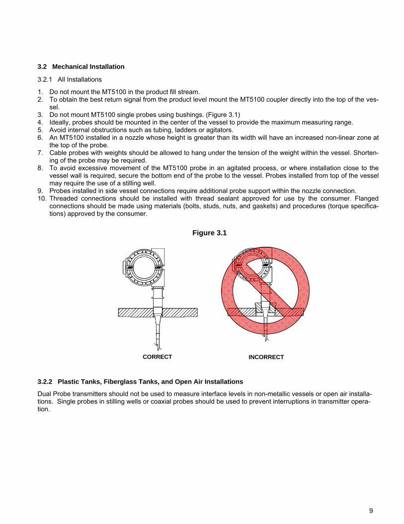
1. Do not mount the MT5100 in the product fill stream. 2. To obtain the best return signal from the product level mount the MT5100 coupler directly into the top of the ves-
sel. 3. Do not mount MT5100 single probes using bushings. (Figure 3.1) 4. Ideally, probes should be mounted in the center of the vessel to provide the maximum measuring range. 5. Avoid internal obstructions such as tubing, ladders or agitators. 6. An MT5100 installed in a nozzle whose height is greater than its width will have an increased non-linear zone at
the top of the probe. 7. Cable probes with weights should be allowed to hang under the tension of the weight within the vessel. Shorten-
ing of the probe may be required. 8. To avoid excessive movement of the MT5100 probe in an agitated process, or where installation close to the
vessel wall is required, secure the bottom end of the probe to the vessel. Probes installed from top of the vessel may require the use of a stilling well.
9. Probes installed in side vessel connections require additional probe support within the nozzle connection. 10. Threaded connections should be installed with thread sealant approved for use by the consumer. Flanged
connections should be made using materials (bolts, studs, nuts, and gaskets) and procedures (torque specifica-tions) approved by the consumer.
INCORRECT
Figure 3.1
CORRECT
3.2.1 All Installations
3.2.2 Plastic Tanks, Fiberglass Tanks, and Open Air Installations
Dual Probe transmitters should not be used to measure interface levels in non-metallic vessels or open air installa-tions. Single probes in stilling wells or coaxial probes should be used to prevent interruptions in transmitter opera-tion.
10
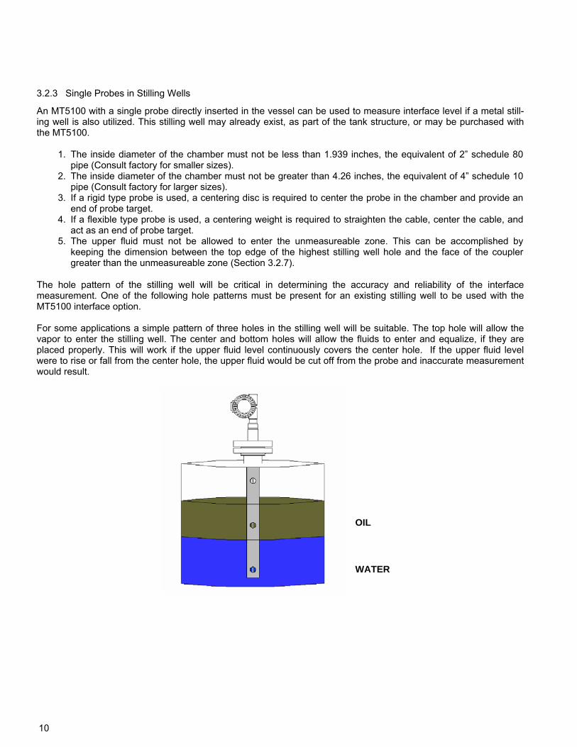
An MT5100 with a single probe directly inserted in the vessel can be used to measure interface level if a metal still-ing well is also utilized. This stilling well may already exist, as part of the tank structure, or may be purchased with the MT5100.
1. The inside diameter of the chamber must not be less than 1.939 inches, the equivalent of 2” schedule 80 pipe (Consult factory for smaller sizes).
2. The inside diameter of the chamber must not be greater than 4.26 inches, the equivalent of 4” schedule 10 pipe (Consult factory for larger sizes).
3. If a rigid type probe is used, a centering disc is required to center the probe in the chamber and provide an end of probe target.
4. If a flexible type probe is used, a centering weight is required to straighten the cable, center the cable, and act as an end of probe target.
5. The upper fluid must not be allowed to enter the unmeasureable zone. This can be accomplished by keeping the dimension between the top edge of the highest stilling well hole and the face of the coupler greater than the unmeasureable zone (Section 3.2.7).
The hole pattern of the stilling well will be critical in determining the accuracy and reliability of the interface measurement. One of the following hole patterns must be present for an existing stilling well to be used with the MT5100 interface option. For some applications a simple pattern of three holes in the stilling well will be suitable. The top hole will allow the vapor to enter the stilling well. The center and bottom holes will allow the fluids to enter and equalize, if they are placed properly. This will work if the upper fluid level continuously covers the center hole. If the upper fluid level were to rise or fall from the center hole, the upper fluid would be cut off from the probe and inaccurate measurement would result.
OIL
WATER
3.2.3 Single Probes in Stilling Wells
11
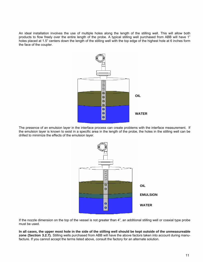
An ideal installation involves the use of multiple holes along the length of the stilling well. This will allow both products to flow freely over the entire length of the probe. A typical stilling well purchased from ABB will have 1” holes placed at 1.5” centers down the length of the stilling well with the top edge of the highest hole at 6 inches form the face of the coupler.
OIL
WATER
The presence of an emulsion layer in the interface process can create problems with the interface measurement. If the emulsion layer is known to exist in a specific area in the length of the probe, the holes in the stilling well can be drilled to minimize the effects of the emulsion layer.
OIL
WATER
EMULSION
If the nozzle dimension on the top of the vessel is not greater than 4”, an additional stilling well or coaxial type probe must be used. In all cases, the upper most hole in the side of the stilling well should be kept outside of the unmeasureable zone (Section 3.2.7). Stilling wells purchased from ABB will have the above factors taken into account during manu-facture. If you cannot accept the terms listed above, consult the factory for an alternate solution.
12
6. A MT5100 Interface option, set for a flooded condition (Figure A), must always remain flooded. Should the chamber become non-flooded during operation, the transmitter will return false indications which could result in process upsets and hazardous conditions.
7. If the configuration is non-flooded (Figure B), the upper fluid must not be allowed to enter the unmeasureable zone. This can be accomplished by keeping the dimension between the top process connection and the access flange greater than the unmeasureable zone (Section 3.2.7).
If the External Chamber for the MT5100 is being supplied by ABB Corporation, all of the above factors will be taken into account during the manufacture. Some interface applications may contain emulsion layers that interfere with the operation of guided wave radar transmitters. Installing the MT5100 in an external chamber will allow the process to settle within the chamber and reduce the affects of the emulsion on the interface level signal.
The single probe MT5100 may be installed in an External Chamber in order to measure interface level. The External Chamber may already exist or be purchased from ABB. There are some guidelines which must be followed in order to maintain proper operation of the transmitter. 1. The inside diameter of the chamber must not be less than 1.939 inches, the equivalent of 2” schedule 80 pipe
(Consult factory for smaller sizes). 2. The inside diameter of the chamber must not be greater than 4.26 inches, the equivalent of 4” schedule 10 pipe
(Consult factory for larger sizes). 3. If a rigid type probe is used, a centering disc is required to center the probe in the chamber and provide an end
of probe target. 4. If a flexible type probe is used, a centering weight is required to straighten the cable, center the cable, and act as
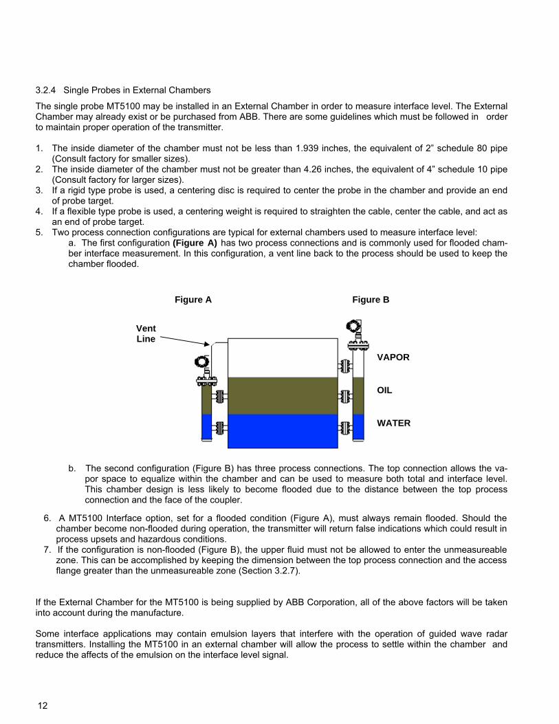
an end of probe target. 5. Two process connection configurations are typical for external chambers used to measure interface level:
a. The first configuration (Figure A) has two process connections and is commonly used for flooded cham-ber interface measurement. In this configuration, a vent line back to the process should be used to keep the chamber flooded.
Figure B Figure A
OIL
WATER
Vent Line
VAPOR
b. The second configuration (Figure B) has three process connections. The top connection allows the va-por space to equalize within the chamber and can be used to measure both total and interface level. This chamber design is less likely to become flooded due to the distance between the top process connection and the face of the coupler.
3.2.4 Single Probes in External Chambers
13
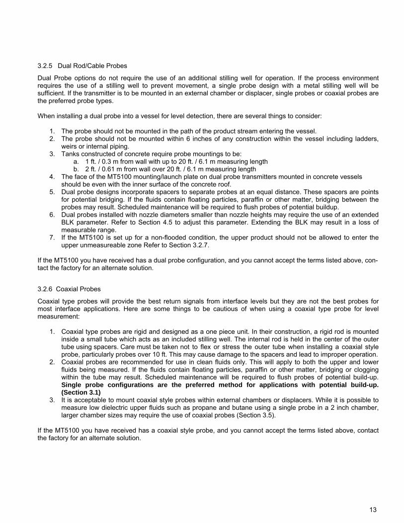
Dual Probe options do not require the use of an additional stilling well for operation. If the process environment requires the use of a stilling well to prevent movement, a single probe design with a metal stilling well will be sufficient. If the transmitter is to be mounted in an external chamber or displacer, single probes or coaxial probes are the preferred probe types. When installing a dual probe into a vessel for level detection, there are several things to consider:
1. The probe should not be mounted in the path of the product stream entering the vessel. 2. The probe should not be mounted within 6 inches of any construction within the vessel including ladders,
weirs or internal piping. 3. Tanks constructed of concrete require probe mountings to be:
a. 1 ft. / 0.3 m from wall with up to 20 ft. / 6.1 m measuring length b. 2 ft. / 0.61 m from wall over 20 ft. / 6.1 m measuring length
4. The face of the MT5100 mounting/launch plate on dual probe transmitters mounted in concrete vessels should be even with the inner surface of the concrete roof.
5. Dual probe designs incorporate spacers to separate probes at an equal distance. These spacers are points for potential bridging. If the fluids contain floating particles, paraffin or other matter, bridging between the probes may result. Scheduled maintenance will be required to flush probes of potential buildup.
6. Dual probes installed with nozzle diameters smaller than nozzle heights may require the use of an extended BLK parameter. Refer to Section 4.5 to adjust this parameter. Extending the BLK may result in a loss of measurable range.
7. If the MT5100 is set up for a non-flooded condition, the upper product should not be allowed to enter the upper unmeasureable zone Refer to Section 3.2.7.
If the MT5100 you have received has a dual probe configuration, and you cannot accept the terms listed above, con-tact the factory for an alternate solution.
3.2.5 Dual Rod/Cable Probes
Coaxial type probes will provide the best return signals from interface levels but they are not the best probes for most interface applications. Here are some things to be cautious of when using a coaxial type probe for level measurement:
1. Coaxial type probes are rigid and designed as a one piece unit. In their construction, a rigid rod is mounted inside a small tube which acts as an included stilling well. The internal rod is held in the center of the outer tube using spacers. Care must be taken not to flex or stress the outer tube when installing a coaxial style probe, particularly probes over 10 ft. This may cause damage to the spacers and lead to improper operation.
2. Coaxial probes are recommended for use in clean fluids only. This will apply to both the upper and lower fluids being measured. If the fluids contain floating particles, paraffin or other matter, bridging or clogging within the tube may result. Scheduled maintenance will be required to flush probes of potential build-up. Single probe configurations are the preferred method for applications with potential build-up. (Section 3.1)
3. It is acceptable to mount coaxial style probes within external chambers or displacers. While it is possible to measure low dielectric upper fluids such as propane and butane using a single probe in a 2 inch chamber, larger chamber sizes may require the use of coaxial probes (Section 3.5).
If the MT5100 you have received has a coaxial style probe, and you cannot accept the terms listed above, contact the factory for an alternate solution.
3.2.6 Coaxial Probes
14
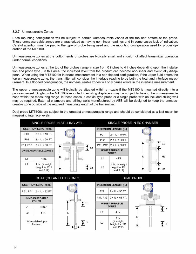
Each mounting configuration will be subject to certain Unmeasurable Zones at the top and bottom of the probe. These unmeasureable zones are characterized as having non-linear readings and in some cases lack of indication. Careful attention must be paid to the type of probe being used and the mounting configuration used for proper op-eration of the MT5100. Unmeasureable zones at the bottom ends of probes are typically small and should not affect transmitter operation under normal conditions. Unmeasureable zones at the top of the probes range in size from 0 inches to 4 inches depending upon the installa-tion and probe type. In this area, the indicated level from the product can become non-linear and eventually disap-pear. When using the MT5100 for interface measurement in a non-flooded configuration, if the upper fluid enters the top unmeasureable zone, the transmitter will consider the interface reading to be both the total and interface meas-urement. In a flooded configuration, the unmeasureable zones will only cause errors in the interface measurement. The upper unmeasureable zone will typically be situated within a nozzle if the MT5100 is mounted directly into a process vessel. Single probe MT5100s mounted in existing displacers may be subject to having the unmeasureable zone within the measuring range. In these cases, a coaxial type probe or a single probe with an included stilling well may be required. External chambers and stilling wells manufactured by ABB will be designed to keep the unmeas-ureable zone outside of the required measuring length of the transmitter. Dual probe MT5100s are subject to the greatest unmeasureable range and should be considered as a last resort for measuring interface levels.
INSERTION LENGTH (IL)
P01 2 < IL < 10 FT.
P02 2 < IL < 20 FT.
P11, P12 2 < IL < 30 FT.
UNMEASURABLE ZONES
L1 4 IN.
L2 1 IN. (+ weight height for P11
and P12)
INSERTION LENGTH (IL)
P51, P71 2 < IL < 22 FT
UNMEASUREABLE ZONES
L1 4 IN.*
L2 1 IN.
* 0” Available Upon Request
IL
L1
L1
ML
INSERTION LENGTH (IL)
P01 2 < IL < 10 FT.
P02 2 < IL < 20 FT.
P11, P12 2 < IL < 30 FT.
UNMEASURABLE ZONES
L1 4 IN.
L2 1 IN. (+ weight height for P11
and P12)
SINGLE PROBE IN STILLING WELL
L2
SINGLE PROBE IN EC CHAMBER
IL
L2
IL
L1
INSERTION LENGTH (IL)
P22 2 < IL < 30 FT.
P31, P32 2 < IL < 65 FT.
UNMEASURABLE ZONES
L1 4 IN.
L2
2 IN. (+ weight,
height for P31 and P32)
DUAL PROBE
L2
IL
L1
7/8”
COAX (CLEAN FLUIDS ONLY)
L2
3.2.7 Unmeasurable Zones
15
The MT5100 single rod and cable probe can be cut to length prior to installation. If shortening of the probe is neces-sary, cut the rod or cable to the desired length using a hacksaw. Shortening of coaxial probes or Tri-Band probes in the field is not recommended. The centering disc or weight at the end of the probe must be reattached for proper operation. The Probe Length parameter in the Basic Setup menu will need to be adjusted for the new probe length.
3.3 Shortening of Probe
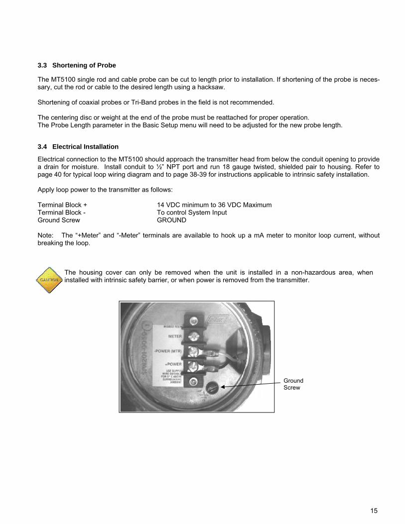
Electrical connection to the MT5100 should approach the transmitter head from below the conduit opening to provide a drain for moisture. Install conduit to ½” NPT port and run 18 gauge twisted, shielded pair to housing. Refer to page 40 for typical loop wiring diagram and to page 38-39 for instructions applicable to intrinsic safety installation. Apply loop power to the transmitter as follows: Terminal Block + 14 VDC minimum to 36 VDC Maximum Terminal Block - To control System Input Ground Screw GROUND Note: The “+Meter” and “-Meter” terminals are available to hook up a mA meter to monitor loop current, without breaking the loop.
3.4 Electrical Installation
The housing cover can only be removed when the unit is installed in a non-hazardous area, when installed with intrinsic safety barrier, or when power is removed from the transmitter.
Ground Screw
16
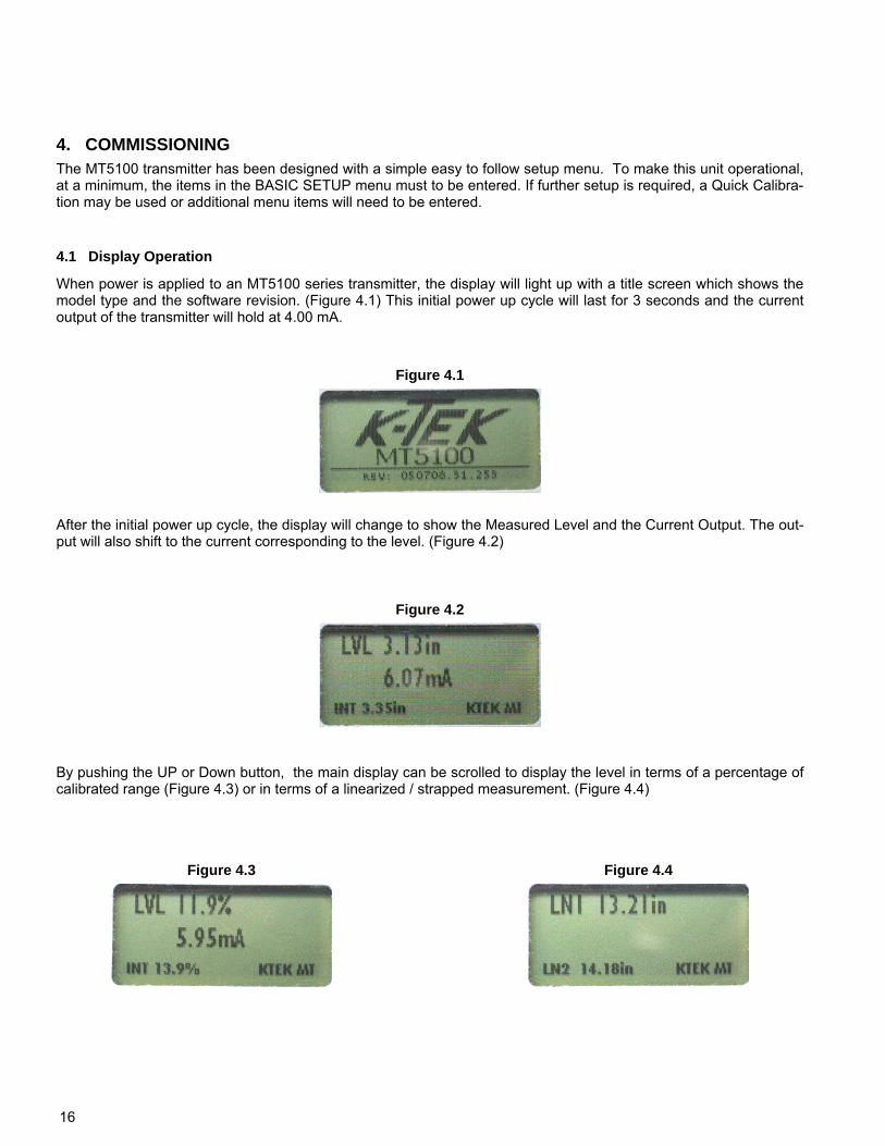
When power is applied to an MT5100 series transmitter, the display will light up with a title screen which shows the model type and the software revision. (Figure 4.1) This initial power up cycle will last for 3 seconds and the current output of the transmitter will hold at 4.00 mA.
After the initial power up cycle, the display will change to show the Measured Level and the Current Output. The out-put will also shift to the current corresponding to the level. (Figure 4.2)
By pushing the UP or Down button, the main display can be scrolled to display the level in terms of a percentage of calibrated range (Figure 4.3) or in terms of a linearized / strapped measurement. (Figure 4.4)
4. COMMISSIONING
4.1 Display Operation
The MT5100 transmitter has been designed with a simple easy to follow setup menu. To make this unit operational, at a minimum, the items in the BASIC SETUP menu must to be entered. If further setup is required, a Quick Calibra-tion may be used or additional menu items will need to be entered.
Figure 4.1
Figure 4.2
Figure 4.3 Figure 4.4
17
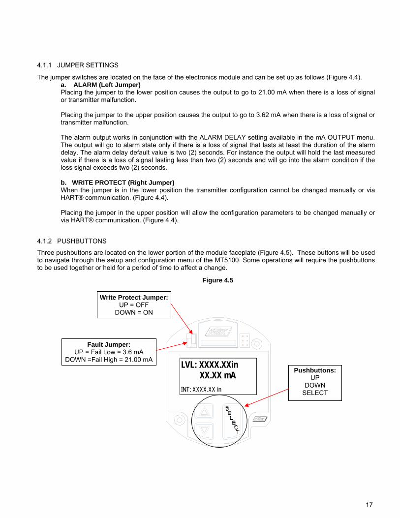
The jumper switches are located on the face of the electronics module and can be set up as follows (Figure 4.4). a. ALARM (Left Jumper)
Placing the jumper to the lower position causes the output to go to 21.00 mA when there is a loss of signal or transmitter malfunction. Placing the jumper to the upper position causes the output to go to 3.62 mA when there is a loss of signal or transmitter malfunction. The alarm output works in conjunction with the ALARM DELAY setting available in the mA OUTPUT menu. The output will go to alarm state only if there is a loss of signal that lasts at least the duration of the alarm delay. The alarm delay default value is two (2) seconds. For instance the output will hold the last measured value if there is a loss of signal lasting less than two (2) seconds and will go into the alarm condition if the loss signal exceeds two (2) seconds.
b. WRITE PROTECT (Right Jumper) When the jumper is in the lower position the transmitter configuration cannot be changed manually or via HART® communication. (Figure 4.4). Placing the jumper in the upper position will allow the configuration parameters to be changed manually or via HART® communication. (Figure 4.4).
Figure 4.5
Fault Jumper: UP = Fail Low = 3.6 mA
DOWN =Fail High = 21.00 mA
Pushbuttons: UP
DOWN SELECT
LVL: XXXX.XXin XX.XX mA
INT: XXXX.XX in
Write Protect Jumper: UP = OFF
DOWN = ON
4.1.1 JUMPER SETTINGS
4.1.2 PUSHBUTTONS
Three pushbuttons are located on the lower portion of the module faceplate (Figure 4.5). These buttons will be used to navigate through the setup and configuration menu of the MT5100. Some operations will require the pushbuttons to be used together or held for a period of time to affect a change.
18
S
S
Section 4.5.4 S
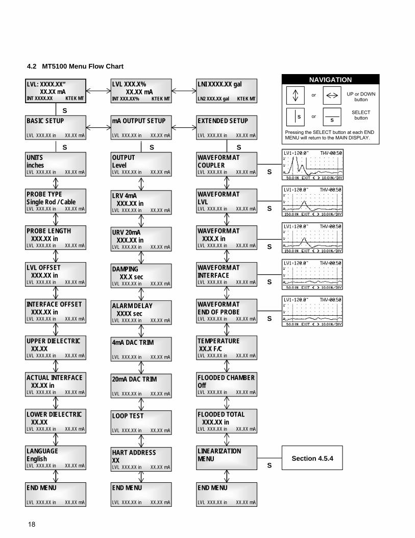
4.2 MT5100 Menu Flow Chart
OUTPUT Level LVL XXX.XX in XX.XX mA
S
S
S
S
S
S
NAVIGATION
UP or DOWN button
SELECT button S
or
S or
Pressing the SELECT button at each END MENU will return to the MAIN DISPLAY.
WAVEFORM AT COUPLER LVL XXX.XX in XX.XX mA
WAVEFORM AT LVL LVL XXX.XX in XX.XX mA
WAVEFORM AT XXX.X in LVL XXX.XX in XX.XX mA
WAVEFORM AT END OF PROBE LVL XXX.XX in XX.XX mA
TEMPERATURE XX.X F/C LVL XXX.XX in XX.XX mA
S
LINEARIZATION MENU
END MENU LVL XXX.XX in XX.XX mA
LANGUAGE English LVL XXX.XX in XX.XX mA
END MENU LVL XXX.XX in XX.XX mA
END MENU LVL XXX.XX in XX.XX mA
HART ADDRESS XX LVL XXX.XX in XX.XX mA
LRV 4mA XXX.XX in LVL XXX.XX in XX.XX mA
URV 20mA XXX.XX in LVL XXX.XX in XX.XX mA
DAMPING XX.X sec LVL XXX.XX in XX.XX mA
ALARM DELAY XXXX sec LVL XXX.XX in XX.XX mA
4mA DAC TRIM LVL XXX.XX in XX.XX mA
20mA DAC TRIM LVL XXX.XX in XX.XX mA
LOOP TEST LVL XXX.XX in XX.XX mA
LVL: XXXX.XX” XX.XX mA INT XXXX.XX KTEK MT
BASIC SETUP LVL XXX.XX in XX.XX mA
UNITS inches LVL XXX.XX in XX.XX mA
PROBE TYPE Single Rod / Cable LVL XXX.XX in XX.XX mA
PROBE LENGTH XXX.XX in LVL XXX.XX in XX.XX mA
LVL OFFSET XXX.XX in LVL XXX.XX in XX.XX mA
LOWER DIELECTRIC XX.XX LVL XXX.XX in XX.XX mA
ACTUAL INTERFACE XX.XX in LVL XXX.XX in XX.XX mA
mA OUTPUT SETUP LVL XXX.XX in XX.XX mA
LVL XXX.X% XX.XX mA INT XXX.XX% KTEK MT
INTERFACE OFFSET XXX.XX in LVL XXX.XX in XX.XX mA
UPPER DIELECTRIC XX.XX LVL XXX.XX in XX.XX mA
EXTENDED SETUP LVL XXX.XX in XX.XX mA
LNI XXXX.XX gal LN2 XXX.XX gal KTEK MT
WAVEFORM AT INTERFACE LVL XXX.XX in XX.XX mA
FLOODED TOTAL XXX.XX in LVL XXX.XX in XX.XX mA
FLOODED CHAMBER Off LVL XXX.XX in XX.XX mA
19
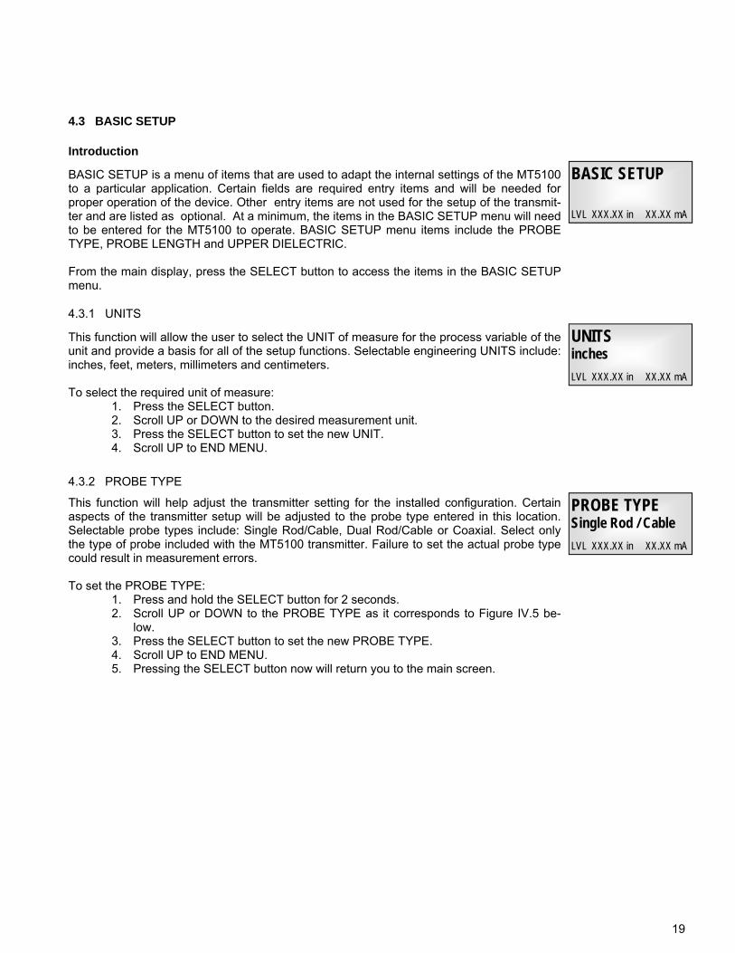
BASIC SETUP is a menu of items that are used to adapt the internal settings of the MT5100 to a particular application. Certain fields are required entry items and will be needed for proper operation of the device. Other entry items are not used for the setup of the transmit-ter and are listed as optional. At a minimum, the items in the BASIC SETUP menu will need to be entered for the MT5100 to operate. BASIC SETUP menu items include the PROBE TYPE, PROBE LENGTH and UPPER DIELECTRIC. From the main display, press the SELECT button to access the items in the BASIC SETUP menu.
BASIC SETUP
LVL XXX.XX in XX.XX mA
Introduction
This function will allow the user to select the UNIT of measure for the process variable of the unit and provide a basis for all of the setup functions. Selectable engineering UNITS include: inches, feet, meters, millimeters and centimeters. To select the required unit of measure:
1. Press the SELECT button. 2. Scroll UP or DOWN to the desired measurement unit. 3. Press the SELECT button to set the new UNIT. 4. Scroll UP to END MENU.
UNITS inches
LVL XXX.XX in XX.XX mA
4.3.1 UNITS
4.3 BASIC SETUP
This function will help adjust the transmitter setting for the installed configuration. Certain aspects of the transmitter setup will be adjusted to the probe type entered in this location. Selectable probe types include: Single Rod/Cable, Dual Rod/Cable or Coaxial. Select only the type of probe included with the MT5100 transmitter. Failure to set the actual probe type could result in measurement errors. To set the PROBE TYPE:
1. Press and hold the SELECT button for 2 seconds. 2. Scroll UP or DOWN to the PROBE TYPE as it corresponds to Figure IV.5 be-
low. 3. Press the SELECT button to set the new PROBE TYPE. 4. Scroll UP to END MENU. 5. Pressing the SELECT button now will return you to the main screen.
PROBE TYPE Single Rod / Cable
LVL XXX.XX in XX.XX mA
4.3.2 PROBE TYPE
20
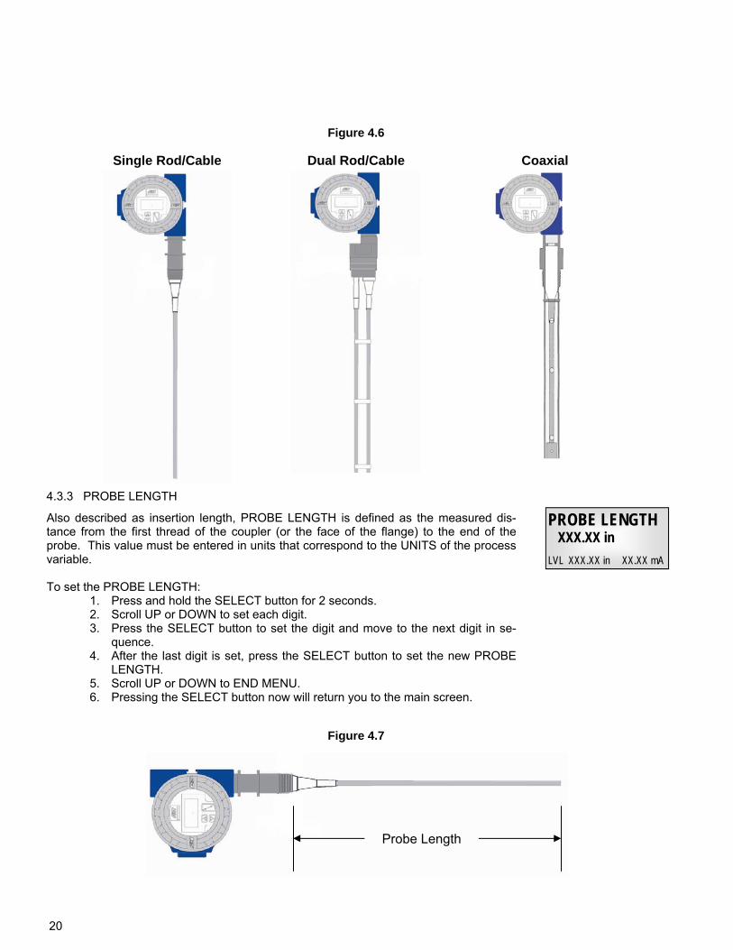
Single Rod/Cable Dual Rod/Cable Coaxial
Figure 4.6
Also described as insertion length, PROBE LENGTH is defined as the measured dis-tance from the first thread of the coupler (or the face of the flange) to the end of the probe. This value must be entered in units that correspond to the UNITS of the process variable. To set the PROBE LENGTH:
1. Press and hold the SELECT button for 2 seconds. 2. Scroll UP or DOWN to set each digit. 3. Press the SELECT button to set the digit and move to the next digit in se-
quence. 4. After the last digit is set, press the SELECT button to set the new PROBE
LENGTH. 5. Scroll UP or DOWN to END MENU. 6. Pressing the SELECT button now will return you to the main screen.
PROBE LENGTH XXX.XX in
LVL XXX.XX in XX.XX mA
4.3.3 PROBE LENGTH
Probe Length
Figure 4.7
21
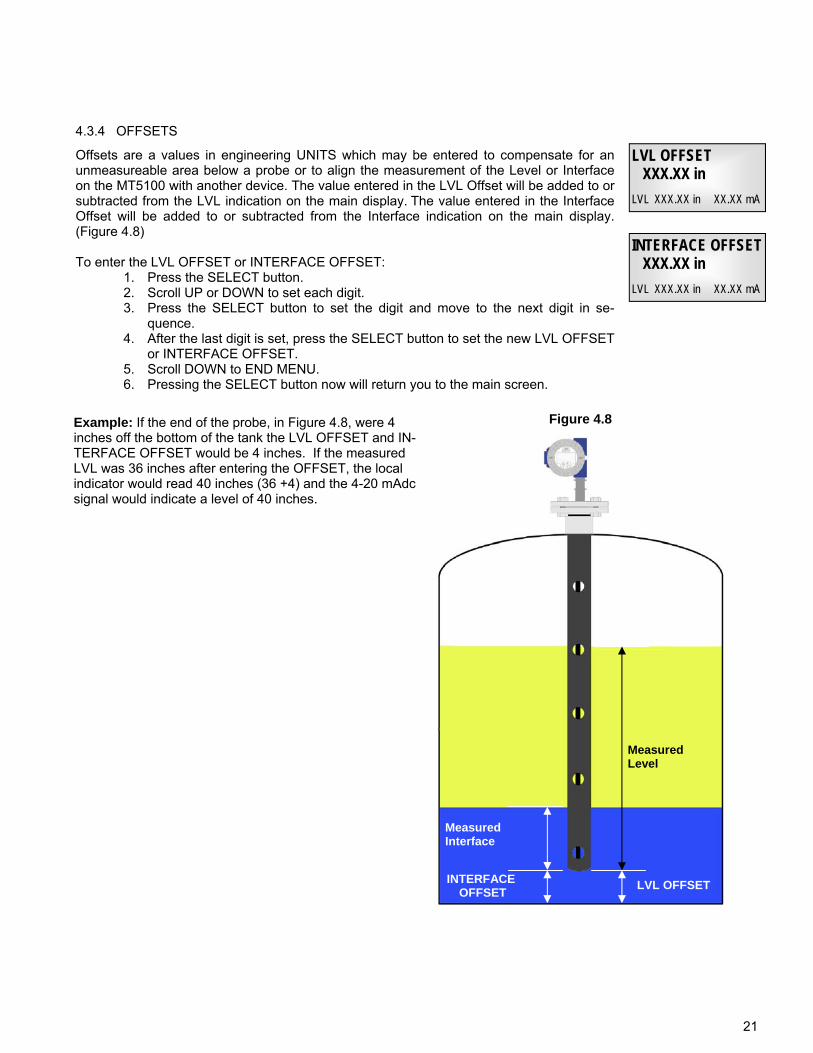
Offsets are a values in engineering UNITS which may be entered to compensate for an unmeasureable area below a probe or to align the measurement of the Level or Interface on the MT5100 with another device. The value entered in the LVL Offset will be added to or subtracted from the LVL indication on the main display. The value entered in the Interface Offset will be added to or subtracted from the Interface indication on the main display. (Figure 4.8) To enter the LVL OFFSET or INTERFACE OFFSET:
1. Press the SELECT button. 2. Scroll UP or DOWN to set each digit. 3. Press the SELECT button to set the digit and move to the next digit in se-
quence. 4. After the last digit is set, press the SELECT button to set the new LVL OFFSET
or INTERFACE OFFSET. 5. Scroll DOWN to END MENU. 6. Pressing the SELECT button now will return you to the main screen.
LVL OFFSET XXX.XX in
LVL XXX.XX in XX.XX mA
4.3.4 OFFSETS
Example: If the end of the probe, in Figure 4.8, were 4 inches off the bottom of the tank the LVL OFFSET and IN-TERFACE OFFSET would be 4 inches. If the measured LVL was 36 inches after entering the OFFSET, the local indicator would read 40 inches (36 +4) and the 4-20 mAdc signal would indicate a level of 40 inches.
INTERFACE OFFSET XXX.XX in
LVL XXX.XX in XX.XX mA
Figure 4.8
LVL OFFSET
Measured Level
Measured Interface
INTERFACE OFFSET
22
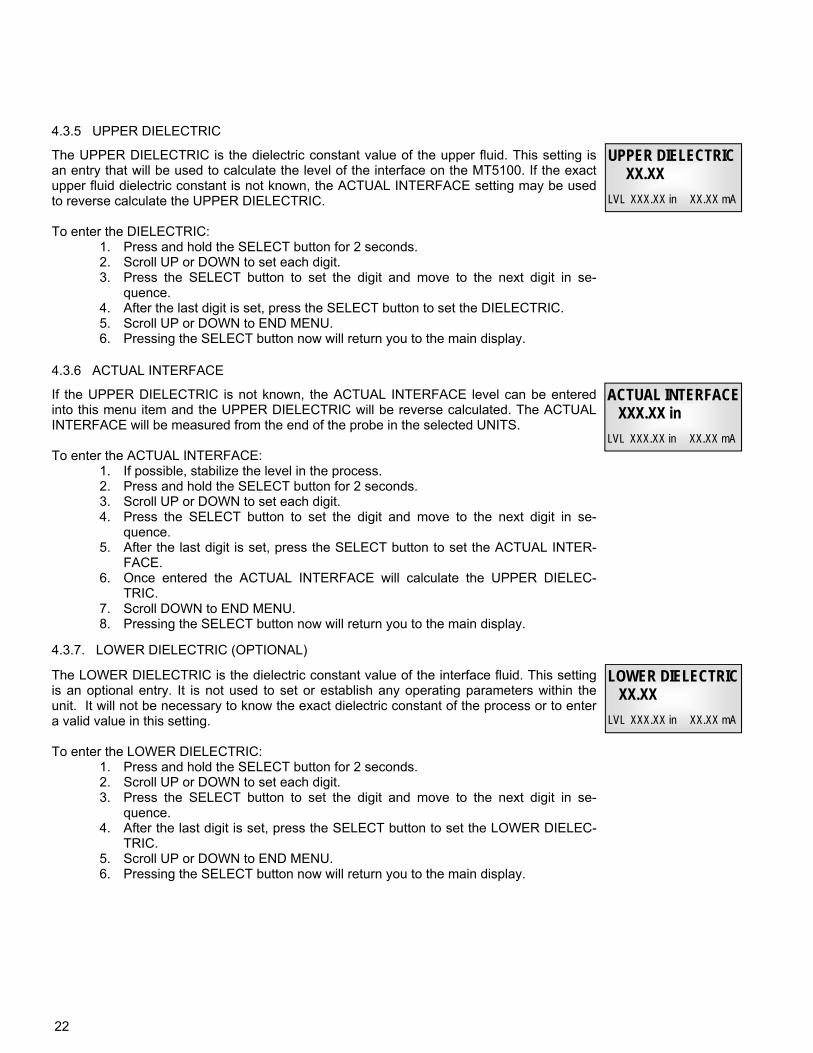
The UPPER DIELECTRIC is the dielectric constant value of the upper fluid. This setting is an entry that will be used to calculate the level of the interface on the MT5100. If the exact upper fluid dielectric constant is not known, the ACTUAL INTERFACE setting may be used to reverse calculate the UPPER DIELECTRIC. To enter the DIELECTRIC:
1. Press and hold the SELECT button for 2 seconds. 2. Scroll UP or DOWN to set each digit. 3. Press the SELECT button to set the digit and move to the next digit in se-
quence. 4. After the last digit is set, press the SELECT button to set the DIELECTRIC. 5. Scroll UP or DOWN to END MENU. 6. Pressing the SELECT button now will return you to the main display.
UPPER DIELECTRIC XX.XX
LVL XXX.XX in XX.XX mA
4.3.5 UPPER DIELECTRIC
4.3.6 ACTUAL INTERFACE
If the UPPER DIELECTRIC is not known, the ACTUAL INTERFACE level can be entered into this menu item and the UPPER DIELECTRIC will be reverse calculated. The ACTUAL INTERFACE will be measured from the end of the probe in the selected UNITS. To enter the ACTUAL INTERFACE:
1. If possible, stabilize the level in the process. 2. Press and hold the SELECT button for 2 seconds. 3. Scroll UP or DOWN to set each digit. 4. Press the SELECT button to set the digit and move to the next digit in se-
quence. 5. After the last digit is set, press the SELECT button to set the ACTUAL INTER-
FACE. 6. Once entered the ACTUAL INTERFACE will calculate the UPPER DIELEC-
TRIC. 7. Scroll DOWN to END MENU. 8. Pressing the SELECT button now will return you to the main display.
ACTUAL INTERFACE XXX.XX in
LVL XXX.XX in XX.XX mA
The LOWER DIELECTRIC is the dielectric constant value of the interface fluid. This setting is an optional entry. It is not used to set or establish any operating parameters within the unit. It will not be necessary to know the exact dielectric constant of the process or to enter a valid value in this setting. To enter the LOWER DIELECTRIC:
1. Press and hold the SELECT button for 2 seconds. 2. Scroll UP or DOWN to set each digit. 3. Press the SELECT button to set the digit and move to the next digit in se-
quence. 4. After the last digit is set, press the SELECT button to set the LOWER DIELEC-
TRIC. 5. Scroll UP or DOWN to END MENU. 6. Pressing the SELECT button now will return you to the main display.
LOWER DIELECTRIC XX.XX
LVL XXX.XX in XX.XX mA
4.3.7. LOWER DIELECTRIC (OPTIONAL)
23
The MT5100 has been equipped with several different operating languages to assist in the setup of the unit. When a specific language is selected, the titles of the menu items will be translated. Abbreviations specific to the MT5100 will remain unchanged as icons regardless of language selection. Available LANGUAGES include:
English French Spanish Portuguese Italian Russian Chinese (Mandarin)
To change the menu LANGUAGE: 1. Press the SELECT button. 2. Scroll UP or DOWN to find the new LANGUAGE. 3. Press the SELECT button to set the new LANGUAGE. 4. Scroll DOWN to END MENU. 5. Pressing the SELECT button now will return you to the main screen.
4.3.8 LANGUAGE
LANGUAGE English
LVL XXX.XX in XX.XX mA
4.4 QUICK CALIBRATION
After the BASIC SETUP menu items have been entered, the MT5100 will be operational. The 4 milliamp output point of the transmitter will be set at the 0 measurement point and the 20 milliamp point will be set at the highest measur-able value. If the probe is measuring the level of the process accurately but is not returning the desired milliamp out-put, it is possible to quickly recalibrate the MT5100 based on the measured level from the transmitter. The OUTPUT setting of the transmitter must correspond to the desired variable for measurement. Use the lower fluid for the follow-ing procedure regardless of the OUTPUT setting.
Setting the 4 milliamp output. 1. Raise or lower the liquid level to the desired 4 milliamp point. 2. Press the UP and DOWN buttons on the MT5100 at the same time. 3. Press the DOWN button to set the 4 milliamp point.
Setting the 20 milliamp output. 1. Raise or lower the liquid level to the desired 20 milliamp point. 2. Press the UP and DOWN buttons on the MT5100 at the same time. 3. Press the UP button to set the 20 milliamp point.
The MT5100 will now be fully operational. If a further detailed setup is required you may proceed to the mA OUT-PUT menu, or the Extended Setup menu. If the output of the MT5100 is required to match that of another device, the following alternate procedure may be used. Setting the 4 milliamp output.
1. Raise or lower the liquid level to the 4 milliamp point of the primary transmitter. 2. Press the UP and DOWN buttons on the MT5100 at the same time. 3. Press the DOWN button to set the 4 milliamp point.
Setting the 20 milliamp output. 1. Raise or lower the liquid level to the 20 milliamp point of the primary transmitter . 2. Press the UP and DOWN buttons on the MT5100 at the same time. 3. Press the UP button to set the 20 milliamp point.
Procedure
Note to User
24
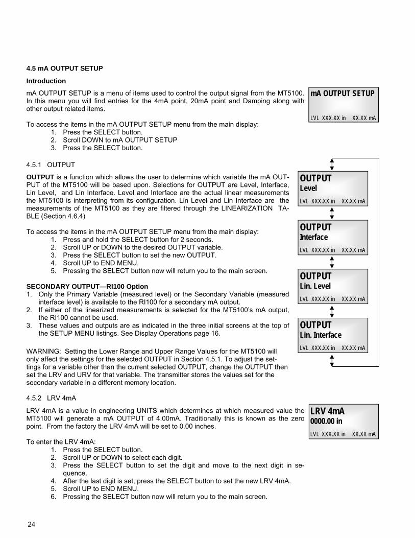
mA OUTPUT SETUP is a menu of items used to control the output signal from the MT5100. In this menu you will find entries for the 4mA point, 20mA point and Damping along with other output related items. To access the items in the mA OUTPUT SETUP menu from the main display:
1. Press the SELECT button. 2. Scroll DOWN to mA OUTPUT SETUP 3. Press the SELECT button.
mA OUTPUT SETUP LVL XXX.XX in XX.XX mA
Introduction
OUTPUT is a function which allows the user to determine which variable the mA OUT-PUT of the MT5100 will be based upon. Selections for OUTPUT are Level, Interface, Lin Level, and Lin Interface. Level and Interface are the actual linear measurements the MT5100 is interpreting from its configuration. Lin Level and Lin Interface are the measurements of the MT5100 as they are filtered through the LINEARIZATION TA-BLE (Section 4.6.4) To access the items in the mA OUTPUT SETUP menu from the main display:
1. Press and hold the SELECT button for 2 seconds. 2. Scroll UP or DOWN to the desired OUTPUT variable. 3. Press the SELECT button to set the new OUTPUT. 4. Scroll UP to END MENU. 5. Pressing the SELECT button now will return you to the main screen.
SECONDARY OUTPUT—RI100 Option 1. Only the Primary Variable (measured level) or the Secondary Variable (measured
interface level) is available to the RI100 for a secondary mA output. 2. If either of the linearized measurements is selected for the MT5100’s mA output,
the RI100 cannot be used. 3. These values and outputs are as indicated in the three initial screens at the top of
the SETUP MENU listings. See Display Operations page 16.
OUTPUT Level
LVL XXX.XX in XX.XX mA
4.5.1 OUTPUT
4.5 mA OUTPUT SETUP
LRV 4mA is a value in engineering UNITS which determines at which measured value the MT5100 will generate a mA OUTPUT of 4.00mA. Traditionally this is known as the zero point. From the factory the LRV 4mA will be set to 0.00 inches. To enter the LRV 4mA:
1. Press the SELECT button. 2. Scroll UP or DOWN to select each digit. 3. Press the SELECT button to set the digit and move to the next digit in se-
quence. 4. After the last digit is set, press the SELECT button to set the new LRV 4mA. 5. Scroll UP to END MENU. 6. Pressing the SELECT button now will return you to the main screen.
LRV 4mA 0000.00 in
LVL XXX.XX in XX.XX mA
4.5.2 LRV 4mA
WARNING: Setting the Lower Range and Upper Range Values for the MT5100 will only affect the settings for the selected OUTPUT in Section 4.5.1. To adjust the set-tings for a variable other than the current selected OUTPUT, change the OUTPUT then set the LRV and URV for that variable. The transmitter stores the values set for the secondary variable in a different memory location.
OUTPUT Interface
LVL XXX.XX in XX.XX mA
OUTPUT Lin. Level
LVL XXX.XX in XX.XX mA
OUTPUT Lin. Interface
LVL XXX.XX in XX.XX mA
25
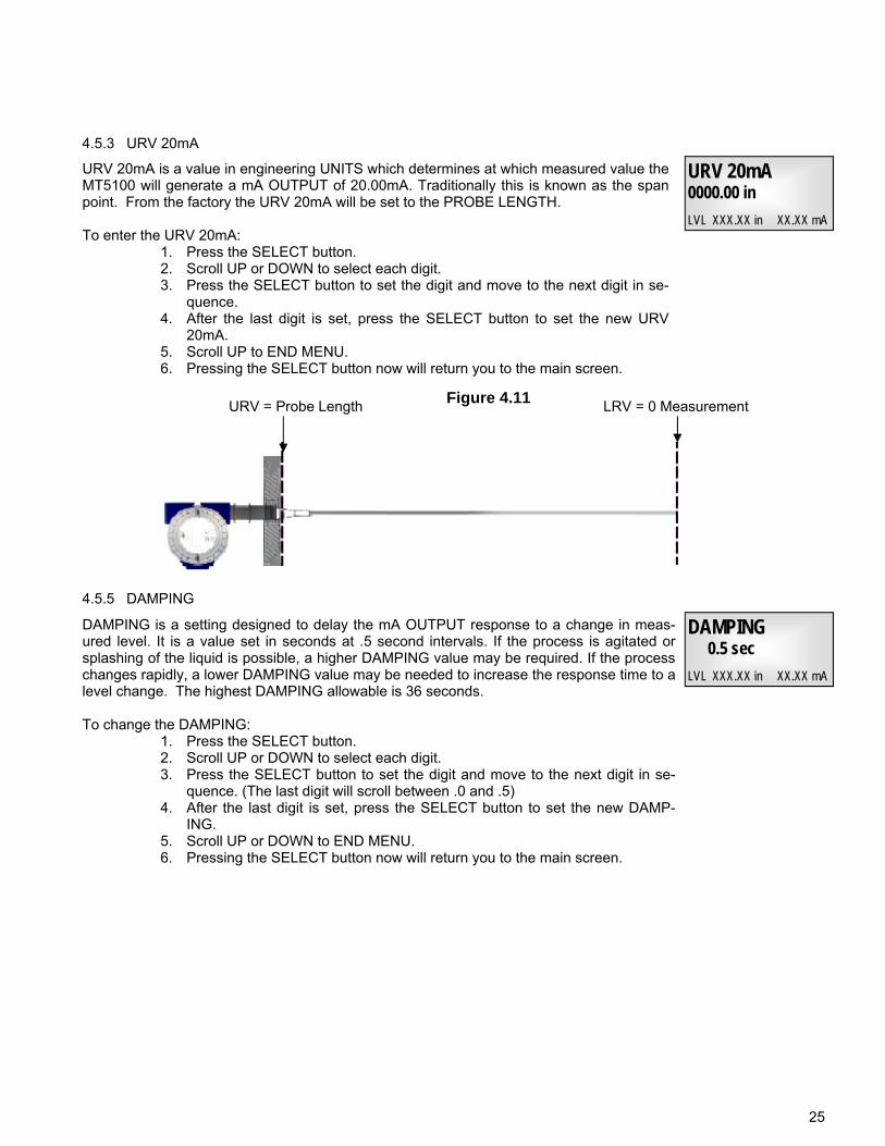
Figure 4.11 URV = Probe Length LRV = 0 Measurement
URV 20mA is a value in engineering UNITS which determines at which measured value the MT5100 will generate a mA OUTPUT of 20.00mA. Traditionally this is known as the span point. From the factory the URV 20mA will be set to the PROBE LENGTH. To enter the URV 20mA:
1. Press the SELECT button. 2. Scroll UP or DOWN to select each digit. 3. Press the SELECT button to set the digit and move to the next digit in se-
quence. 4. After the last digit is set, press the SELECT button to set the new URV
20mA. 5. Scroll UP to END MENU. 6. Pressing the SELECT button now will return you to the main screen.
URV 20mA 0000.00 in
LVL XXX.XX in XX.XX mA
4.5.3 URV 20mA
DAMPING is a setting designed to delay the mA OUTPUT response to a change in meas-ured level. It is a value set in seconds at .5 second intervals. If the process is agitated or splashing of the liquid is possible, a higher DAMPING value may be required. If the process changes rapidly, a lower DAMPING value may be needed to increase the response time to a level change. The highest DAMPING allowable is 36 seconds. To change the DAMPING:
1. Press the SELECT button. 2. Scroll UP or DOWN to select each digit. 3. Press the SELECT button to set the digit and move to the next digit in se-
quence. (The last digit will scroll between .0 and .5) 4. After the last digit is set, press the SELECT button to set the new DAMP-
ING. 5. Scroll UP or DOWN to END MENU. 6. Pressing the SELECT button now will return you to the main screen.
DAMPING 0.5 sec
LVL XXX.XX in XX.XX mA
4.5.5 DAMPING
26
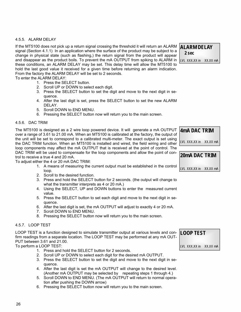
If the MT5100 does not pick up a return signal crossing the threshold it will return an ALARM signal (Section 4.1.1) In an application where the surface of the product may be subject to a change in physical state (such as flashing,) the return signal from the product will appear and disappear as the product boils. To prevent the mA OUTPUT from spiking to ALARM in these conditions, an ALARM DELAY may be set. This delay time will allow the MT5100 to hold the last good value it received for a given time before returning an alarm indication. From the factory the ALARM DELAY will be set to 2 seconds. To enter the ALARM DELAY:
1. Press the SELECT button. 2. Scroll UP or DOWN to select each digit. 3. Press the SELECT button to set the digit and move to the next digit in se-
quence. 4. After the last digit is set, press the SELECT button to set the new ALARM
DELAY. 5. Scroll DOWN to END MENU. 6. Pressing the SELECT button now will return you to the main screen.
ALARM DELAY 2 sec
LVL XXX.XX in XX.XX mA
4.5.5. ALARM DELAY
The MT5100 is designed as a 2 wire loop powered device. It will generate a mA OUTPUT over a range of 3.61 to 21.00 mA. When an MT5100 is calibrated at the factory, the output of the unit will be set to correspond to a calibrated multi-meter. The exact output is set using the DAC TRIM function. When an MT5100 is installed and wired, the field wiring and other loop components may affect the mA OUTPUT that is received at the point of control. The DAC TRIM will be used to compensate for the loop components and allow the point of con-trol to receive a true 4 and 20 mA. To adjust either the 4 or 20 mA DAC TRIM:
1. A means of measuring the current output must be established in the control loop.
2. Scroll to the desired function. 3. Press and hold the SELECT button for 2 seconds. (the output will change to
what the transmitter interprets as 4 or 20 mA.) 4. Using the SELECT, UP and DOWN buttons to enter the measured current
value. 5. Press the SELECT button to set each digit and move to the next digit in se-
quence. 6. After the last digit is set, the mA OUTPUT will adjust to exactly 4 or 20 mA. 7. Scroll DOWN to END MENU. 8. Pressing the SELECT button now will return you to the main screen.
4mA DAC TRIM
LVL XXX.XX in XX.XX mA
4.5.6. DAC TRIM
20mA DAC TRIM
LVL XXX.XX in XX.XX mA
LOOP TEST is a function designed to simulate transmitter output at various levels and con-firm readings from a separate location. The LOOP TEST may be performed at any mA OUT-PUT between 3.61 and 21.00. To perform a LOOP TEST:
1. Press and hold the SELECT button for 2 seconds. 2. Scroll UP or DOWN to select each digit for the desired mA OUTPUT. 3. Press the SELECT button to set the digit and move to the next digit in se-
quence. 4. After the last digit is set the mA OUTPUT will change to the desired level.
(Another mA OUTPUT may be selected by repeating steps 1 through 4.) 5. Scroll DOWN to END MENU. (The mA OUTPUT will return to normal opera-
tion after pushing the DOWN arrow) 6. Pressing the SELECT button now will return you to the main screen.
LOOP TEST
LVL XXX.XX in XX.XX mA
4.5.7. LOOP TEST
27
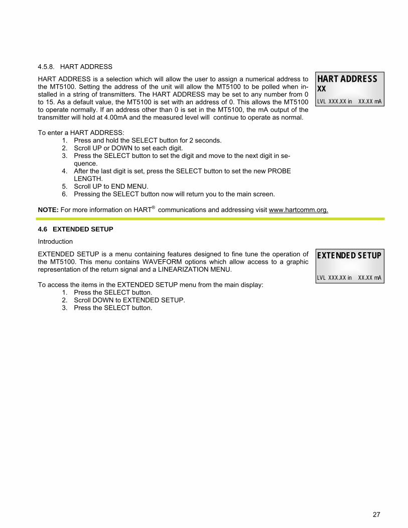
HART ADDRESS is a selection which will allow the user to assign a numerical address to the MT5100. Setting the address of the unit will allow the MT5100 to be polled when in-stalled in a string of transmitters. The HART ADDRESS may be set to any number from 0 to 15. As a default value, the MT5100 is set with an address of 0. This allows the MT5100 to operate normally. If an address other than 0 is set in the MT5100, the mA output of the transmitter will hold at 4.00mA and the measured level will continue to operate as normal. To enter a HART ADDRESS:
1. Press and hold the SELECT button for 2 seconds. 2. Scroll UP or DOWN to set each digit. 3. Press the SELECT button to set the digit and move to the next digit in se-
quence. 4. After the last digit is set, press the SELECT button to set the new PROBE
LENGTH. 5. Scroll UP to END MENU. 6. Pressing the SELECT button now will return you to the main screen.
HART ADDRESS XX
LVL XXX.XX in XX.XX mA
4.5.8. HART ADDRESS
NOTE: For more information on HART® communications and addressing visit www.hartcomm.org.
EXTENDED SETUP is a menu containing features designed to fine tune the operation of the MT5100. This menu contains WAVEFORM options which allow access to a graphic representation of the return signal and a LINEARIZATION MENU. To access the items in the EXTENDED SETUP menu from the main display:
1. Press the SELECT button. 2. Scroll DOWN to EXTENDED SETUP. 3. Press the SELECT button.
EXTENDED SETUP
LVL XXX.XX in XX.XX mA
Introduction
4.6 EXTENDED SETUP
28
4.6.1 WAVEFORM DISPLAY
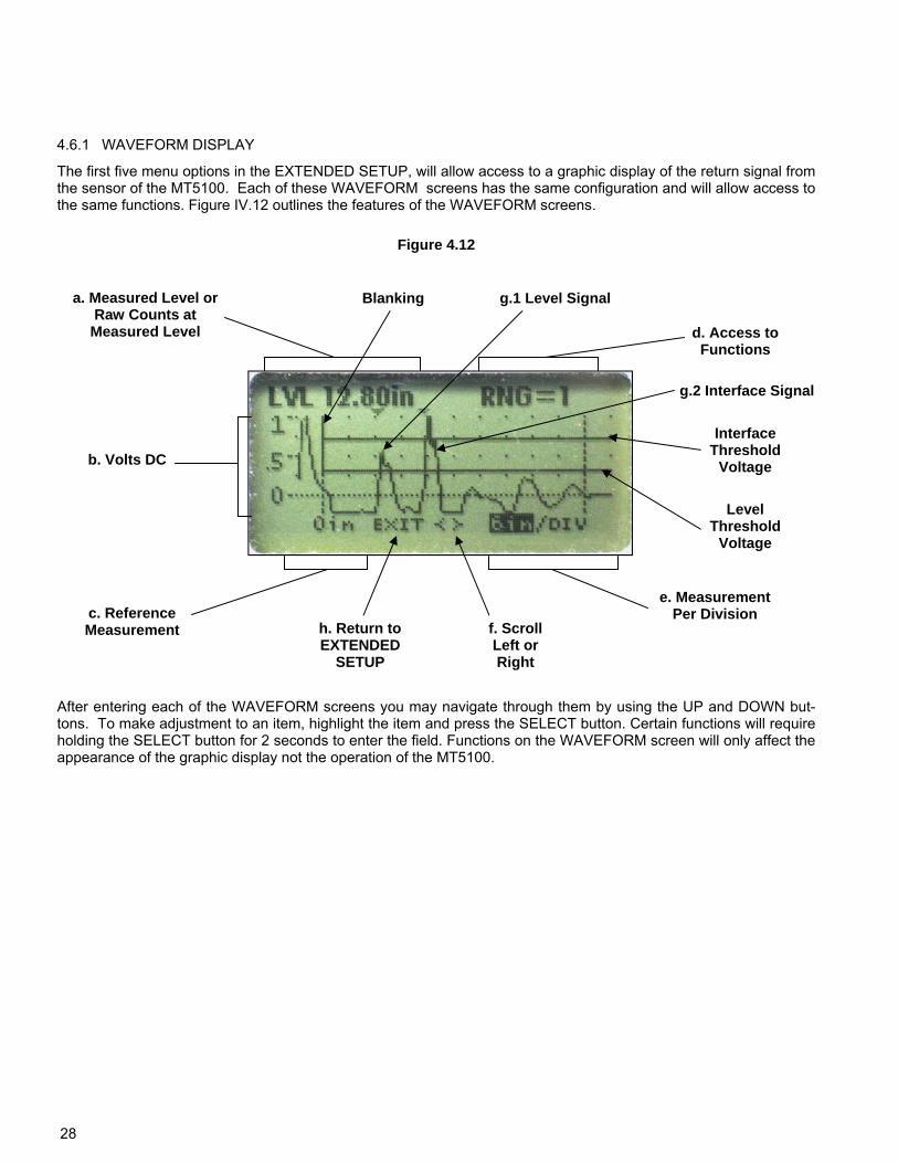
The first five menu options in the EXTENDED SETUP, will allow access to a graphic display of the return signal from the sensor of the MT5100. Each of these WAVEFORM screens has the same configuration and will allow access to the same functions. Figure IV.12 outlines the features of the WAVEFORM screens.
Figure 4.12
a. Measured Level or Raw Counts at
Measured Level
c. Reference Measurement h. Return to
EXTENDED SETUP
f. Scroll Left or Right
e. Measurement Per Division
b. Volts DC
Level Threshold
Voltage
d. Access to Functions
Blanking
g.2 Interface Signal
Interface Threshold
Voltage
g.1 Level Signal
After entering each of the WAVEFORM screens you may navigate through them by using the UP and DOWN but-tons. To make adjustment to an item, highlight the item and press the SELECT button. Certain functions will require holding the SELECT button for 2 seconds to enter the field. Functions on the WAVEFORM screen will only affect the appearance of the graphic display not the operation of the MT5100.
29
a. Measured Level / Raw Counts - Displays the Media Level as determined by the transmitter. Pressing the SE-LECT button here will scroll this portion of the display between the Measured Level and the Raw Counts at the Measured Level.
b. Volts DC - Scaling of the graphic display from 0 to 1 VDC. The return signal will rise up from 0 volts towards 1 volt.
c. Reference Measurement - The dotted vertical line to the left of the display provides a reference measurement for the WAVEFORM. The measured value at this dotted line will be displayed in the bottom left hand portion of the screen and provide a starting point for determining the position of the signal. Reference measurements are made from the face of the coupler or the mounting flange.
d. Access to Functions - This section will allow entry to separate menu items to adjust the appearance of the sig-nal and the signal detection capabilities. Some of these settings will be determined by the values entered in the BASIC SETUP menu and adjustments made to these settings are to be made only when absolutely necessary. (Section 4.5.2)
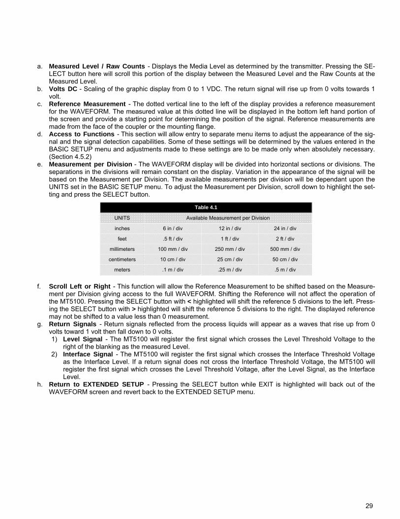
e. Measurement per Division - The WAVEFORM display will be divided into horizontal sections or divisions. The separations in the divisions will remain constant on the display. Variation in the appearance of the signal will be based on the Measurement per Division. The available measurements per division will be dependant upon the UNITS set in the BASIC SETUP menu. To adjust the Measurement per Division, scroll down to highlight the set-ting and press the SELECT button.
f. Scroll Left or Right - This function will allow the Reference Measurement to be shifted based on the Measure-
ment per Division giving access to the full WAVEFORM. Shifting the Reference will not affect the operation of the MT5100. Pressing the SELECT button with < highlighted will shift the reference 5 divisions to the left. Press-ing the SELECT button with > highlighted will shift the reference 5 divisions to the right. The displayed reference may not be shifted to a value less than 0 measurement.
g. Return Signals - Return signals reflected from the process liquids will appear as a waves that rise up from 0 volts toward 1 volt then fall down to 0 volts. 1) Level Signal - The MT5100 will register the first signal which crosses the Level Threshold Voltage to the
right of the blanking as the measured Level. 2) Interface Signal - The MT5100 will register the first signal which crosses the Interface Threshold Voltage
as the Interface Level. If a return signal does not cross the Interface Threshold Voltage, the MT5100 will register the first signal which crosses the Level Threshold Voltage, after the Level Signal, as the Interface Level.
h. Return to EXTENDED SETUP - Pressing the SELECT button while EXIT is highlighted will back out of the WAVEFORM screen and revert back to the EXTENDED SETUP menu.
UNITS Available Measurement per Division
inches 6 in / div 12 in / div 24 in / div
feet .5 ft / div 1 ft / div 2 ft / div
millimeters 100 mm / div 250 mm / div 500 mm / div
centimeters 10 cm / div 25 cm / div 50 cm / div
meters .1 m / div .25 m / div .5 m / div
Table 4.1
30
4.6.2 FUNCTIONS
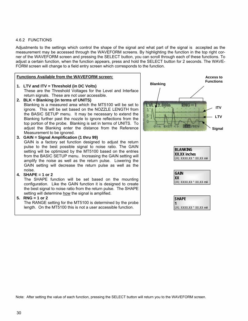
Adjustments to the settings which control the shape of the signal and what part of the signal is accepted as the measurement may be accessed through the WAVEFORM screens. By highlighting the function in the top right cor-ner of the WAVEFORM screen and pressing the SELECT button, you can scroll through each of these functions. To adjust a certain function, when the function appears, press and hold the SELECT button for 2 seconds. The WAVE-FORM screen will change to a field entry screen which corresponds to the function.
Functions Available from the WAVEFORM screen: 1. LTV and ITV = Threshold (in DC Volts) These are the Threshold Voltages for the Level and Interface
return signals. These are not user accessible. 2. BLK = Blanking (in terms of UNITS) Blanking is a measured area which the MT5100 will be set to
ignore. This will be set based on the NOZZLE LENGTH from the BASIC SETUP menu. It may be necessary to extend the Blanking further past the nozzle to ignore reflections from the top portion of the probe. Blanking is set in terms of UNITS. To adjust the Blanking enter the distance from the Reference Measurement to be ignored.
3. GAIN = Signal Amplification (1 thru 99) GAIN is a factory set function designed to adjust the return
pulse to the best possible signal to noise ratio. The GAIN setting will be optimized by the MT5100 based on the entries from the BASIC SETUP menu. Increasing the GAIN setting will amplify the noise as well as the return pulse. Lowering the GAIN setting will decrease the return pulse as well as the noise.
4. SHAPE = 1 or 2 The SHAPE function will be set based on the mounting
configuration. Like the GAIN function it is designed to create the best signal to noise ratio from the return pulse. The SHAPE setting will determine how the signal is amplified.
5. RNG = 1 or 2 The RANGE setting for the MT5100 is determined by the probe
length. On the MT5100 this is not a user accessible function.
BLANKING XX.XX inches LVL: XXXX.XX “ XX.XX mA
GAIN XX LVL: XXXX.XX “ XX.XX mA
SHAPE 1 LVL: XXXX.XX “ XX.XX mA
Access to Functions
LTV
Blanking
Signal
Note: After setting the value of each function, pressing the SELECT button will return you to the WAVEFORM screen.
ITV
31
FLOODED TOTAL XXX.XX in
LVL XXX.XX in XX.XX mA
FLOODEDCHAMBER
Off LVL XXX.XX in XX.XX mA
4.6.3 TEMPERATURE
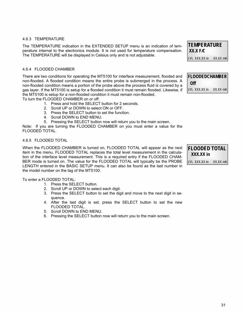
The TEMPERATURE indication in the EXTENDED SETUP menu is an indication of tem-perature internal to the electronics module. It is not used for temperature compensation. The TEMPERATURE will be displayed in Celsius only and is not adjustable.
4.6.4 FLOODED CHAMBER
4.6.5 FLOODED TOTAL
There are two conditions for operating the MT5100 for interface measurement, flooded and non-flooded. A flooded condition means the entire probe is submerged in the process. A non-flooded condition means a portion of the probe above the process fluid is covered by a gas layer. If the MT5100 is setup for a flooded condition it must remain flooded. Likewise, if the MT5100 is setup for a non-flooded condition it must remain non-flooded. To turn the FLOODED CHAMBER on or off:
1. Press and hold the SELECT button for 2 seconds. 2. Scroll UP or DOWN to select ON or OFF. 3. Press the SELECT button to set the function. 4. Scroll DOWN to END MENU. 5. Pressing the SELECT button now will return you to the main screen.
Note: If you are turning the FLOODED CHAMBER on you must enter a value for the FLOODED TOTAL.
When the FLOODED CHAMBER is turned on, FLOODED TOTAL will appear as the next item in the menu. FLOODED TOTAL replaces the total level measurement in the calcula-tion of the interface level measurement. This is a required entry if the FLOODED CHAM-BER mode is turned on. The value for the FLOODED TOTAL will typically be the PROBE LENGTH entered in the BASIC SETUP menu. It can also be found as the last number in the model number on the tag of the MT5100. To enter a FLOODED TOTAL:
1. Press the SELECT button. 2. Scroll UP or DOWN to select each digit. 3. Press the SELECT button to set the digit and move to the next digit in se-
quence. 4. After the last digit is set, press the SELECT button to set the new
FLOODED TOTAL. 5. Scroll DOWN to END MENU. 6. Pressing the SELECT button now will return you to the main screen.
TEMPERATURE XX.X F/C
LVL XXX.XX in XX.XX mA
32
4.6.6 LINEARIZATION MENU
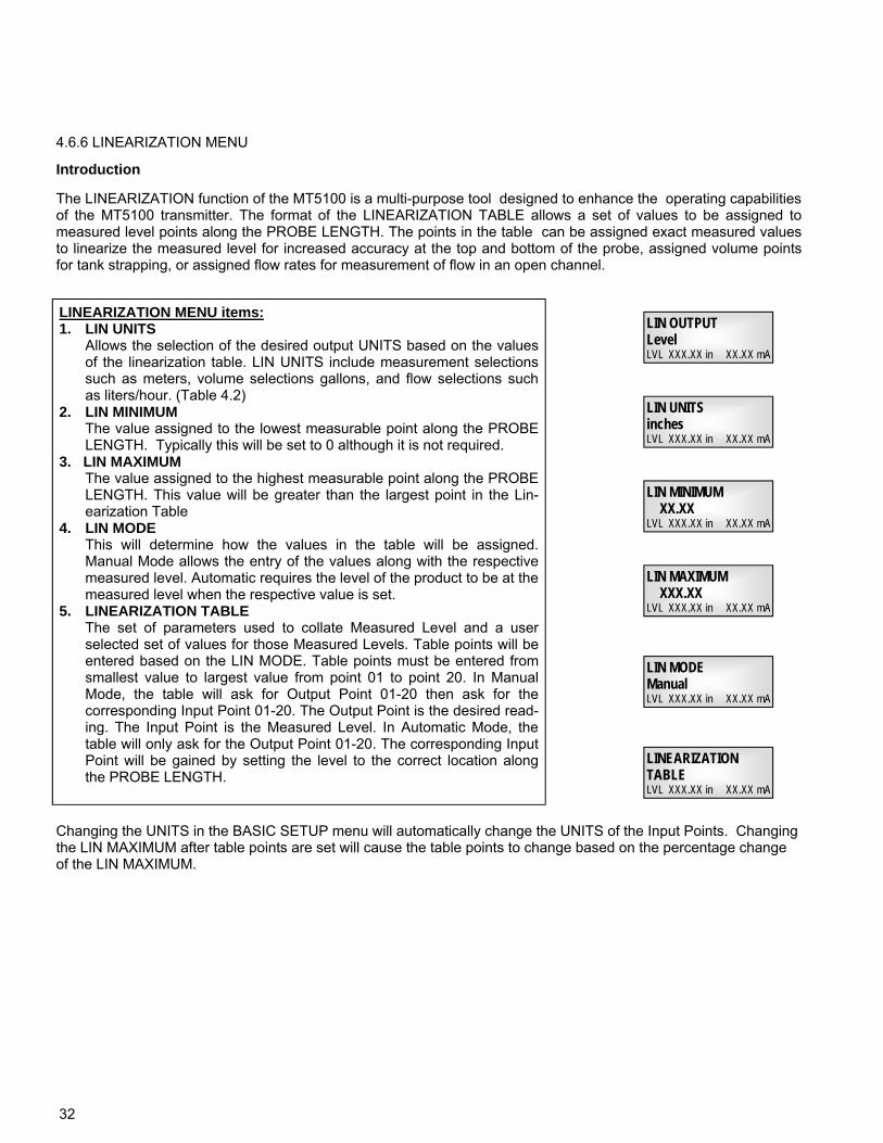
The LINEARIZATION function of the MT5100 is a multi-purpose tool designed to enhance the operating capabilities of the MT5100 transmitter. The format of the LINEARIZATION TABLE allows a set of values to be assigned to measured level points along the PROBE LENGTH. The points in the table can be assigned exact measured values to linearize the measured level for increased accuracy at the top and bottom of the probe, assigned volume points for tank strapping, or assigned flow rates for measurement of flow in an open channel.
LIN UNITS inches LVL XXX.XX in XX.XX mA
LIN MINIMUM XX.XX LVL XXX.XX in XX.XX mA
LIN MAXIMUM XXX.XX LVL XXX.XX in XX.XX mA
LIN MODE Manual LVL XXX.XX in XX.XX mA
LINEARIZATION TABLE LVL XXX.XX in XX.XX mA
LINEARIZATION MENU items: 1. LIN UNITS Allows the selection of the desired output UNITS based on the values
of the linearization table. LIN UNITS include measurement selections such as meters, volume selections gallons, and flow selections such as liters/hour. (Table 4.2)
2. LIN MINIMUM The value assigned to the lowest measurable point along the PROBE
LENGTH. Typically this will be set to 0 although it is not required. 3. LIN MAXIMUM The value assigned to the highest measurable point along the PROBE
LENGTH. This value will be greater than the largest point in the Lin-earization Table
4. LIN MODE This will determine how the values in the table will be assigned.
Manual Mode allows the entry of the values along with the respective measured level. Automatic requires the level of the product to be at the measured level when the respective value is set.
5. LINEARIZATION TABLE The set of parameters used to collate Measured Level and a user
selected set of values for those Measured Levels. Table points will be entered based on the LIN MODE. Table points must be entered from smallest value to largest value from point 01 to point 20. In Manual Mode, the table will ask for Output Point 01-20 then ask for the corresponding Input Point 01-20. The Output Point is the desired read-ing. The Input Point is the Measured Level. In Automatic Mode, the table will only ask for the Output Point 01-20. The corresponding Input Point will be gained by setting the level to the correct location along the PROBE LENGTH.
Changing the UNITS in the BASIC SETUP menu will automatically change the UNITS of the Input Points. Changing the LIN MAXIMUM after table points are set will cause the table points to change based on the percentage change of the LIN MAXIMUM.
Introduction
LIN OUTPUT Level LVL XXX.XX in XX.XX mA
33
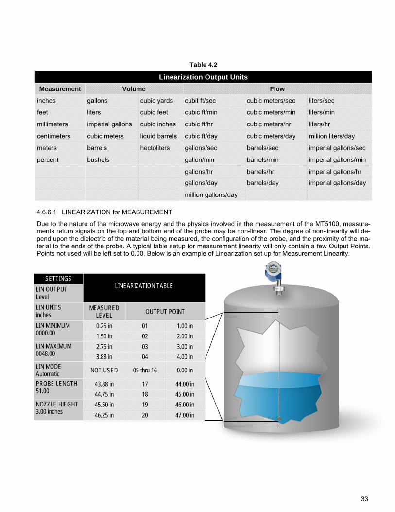
Linearization Output Units
Measurement Flow
inches gallons cubic yards cubit ft/sec cubic meters/sec liters/sec
feet liters cubic feet cubic ft/min cubic meters/min liters/min
millimeters imperial gallons cubic inches cubic ft/hr cubic meters/hr liters/hr
centimeters cubic meters liquid barrels cubic ft/day cubic meters/day million liters/day
meters barrels hectoliters gallons/sec barrels/sec imperial gallons/sec
percent bushels gallon/min barrels/min imperial gallons/min
gallons/hr barrels/hr imperial gallons/hr
gallons/day barrels/day imperial gallons/day
million gallons/day
Volume
4.6.6.1 LINEARIZATION for MEASUREMENT
Table 4.2
Due to the nature of the microwave energy and the physics involved in the measurement of the MT5100, measure-ments return signals on the top and bottom end of the probe may be non-linear. The degree of non-linearity will de-pend upon the dielectric of the material being measured, the configuration of the probe, and the proximity of the ma-terial to the ends of the probe. A typical table setup for measurement linearity will only contain a few Output Points. Points not used will be left set to 0.00. Below is an example of Linearization set up for Measurement Linearity.
SETTINGS
LIN OUTPUT Level
LIN UNITS inches
MEASURED LEVEL OUTPUT POINT
LIN MINIMUM 0000.00
0.25 in 01 1.00 in
1.50 in 02 2.00 in
LIN MAXIMUM 0048.00
2.75 in 03 3.00 in
3.88 in 04 4.00 in
LIN MODE Automatic NOT USED 05 thru 16 0.00 in
PROBE LENGTH 51.00
43.88 in 17 44.00 in
44.75 in 18 45.00 in
NOZZLE HIEGHT 3.00 inches
45.50 in 19 46.00 in
46.25 in 20 47.00 in
LINEARIZATION TABLE
34
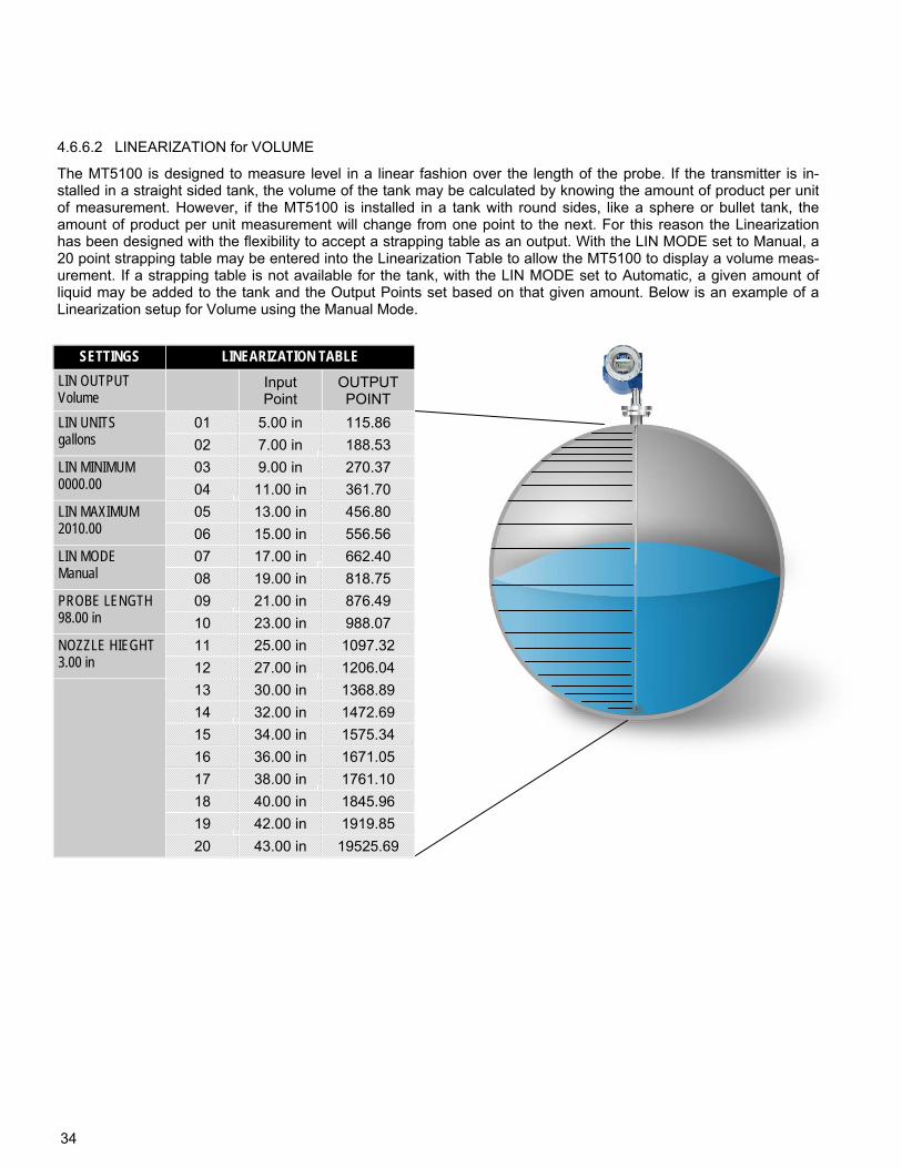
4.6.6.2 LINEARIZATION for VOLUME
The MT5100 is designed to measure level in a linear fashion over the length of the probe. If the transmitter is in-stalled in a straight sided tank, the volume of the tank may be calculated by knowing the amount of product per unit of measurement. However, if the MT5100 is installed in a tank with round sides, like a sphere or bullet tank, the amount of product per unit measurement will change from one point to the next. For this reason the Linearization has been designed with the flexibility to accept a strapping table as an output. With the LIN MODE set to Manual, a 20 point strapping table may be entered into the Linearization Table to allow the MT5100 to display a volume meas-urement. If a strapping table is not available for the tank, with the LIN MODE set to Automatic, a given amount of liquid may be added to the tank and the Output Points set based on that given amount. Below is an example of a Linearization setup for Volume using the Manual Mode.
SETTINGS LINEARIZATION TABLE
LIN OUTPUT Volume
Input Point
OUTPUT POINT
LIN UNITS gallons
01 5.00 in 115.86
02 7.00 in 188.53
LIN MINIMUM 0000.00
03 9.00 in 270.37
04 11.00 in 361.70
LIN MAXIMUM 2010.00
05 13.00 in 456.80
06 15.00 in 556.56
LIN MODE Manual
07 17.00 in 662.40
08 19.00 in 818.75
PROBE LENGTH 98.00 in
09 21.00 in 876.49
10 23.00 in 988.07
NOZZLE HIEGHT 3.00 in
11 25.00 in 1097.32
12 27.00 in 1206.04
13 30.00 in 1368.89
14 32.00 in 1472.69
15 34.00 in 1575.34
16 36.00 in 1671.05
17 38.00 in 1761.10
18 40.00 in 1845.96
19 42.00 in 1919.85
20 43.00 in 19525.69
35
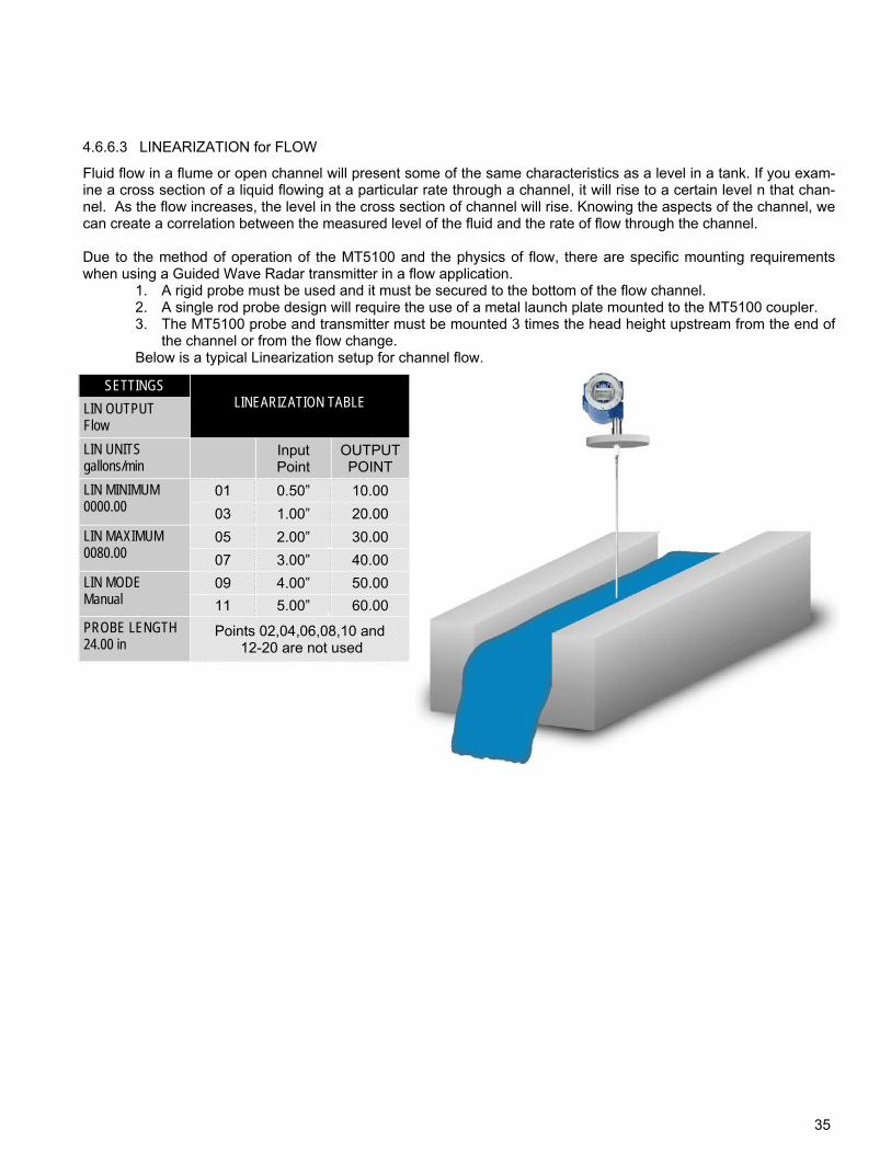
Fluid flow in a flume or open channel will present some of the same characteristics as a level in a tank. If you exam-ine a cross section of a liquid flowing at a particular rate through a channel, it will rise to a certain level n that chan-nel. As the flow increases, the level in the cross section of channel will rise. Knowing the aspects of the channel, we can create a correlation between the measured level of the fluid and the rate of flow through the channel. Due to the method of operation of the MT5100 and the physics of flow, there are specific mounting requirements when using a Guided Wave Radar transmitter in a flow application.
1. A rigid probe must be used and it must be secured to the bottom of the flow channel. 2. A single rod probe design will require the use of a metal launch plate mounted to the MT5100 coupler. 3. The MT5100 probe and transmitter must be mounted 3 times the head height upstream from the end of
the channel or from the flow change. Below is a typical Linearization setup for channel flow.
SETTINGS
LIN OUTPUT Flow
LIN UNITS gallons/min
Input Point
OUTPUT POINT
LIN MINIMUM 0000.00
01 0.50” 10.00
03 1.00” 20.00
LIN MAXIMUM 0080.00
05 2.00” 30.00
07 3.00” 40.00
LIN MODE Manual
09 4.00” 50.00
11 5.00” 60.00
PROBE LENGTH 24.00 in
Points 02,04,06,08,10 and 12-20 are not used
LINEARIZATION TABLE
4.6.6.3 LINEARIZATION for FLOW
36
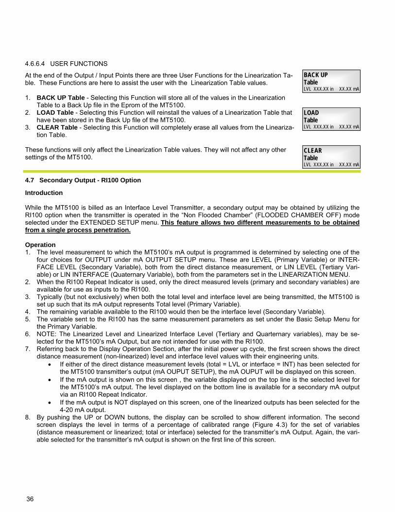
4.6.6.4 USER FUNCTIONS
BACK UP Table LVL XXX.XX in XX.XX mA
LOAD Table LVL XXX.XX in XX.XX mA
CLEAR Table LVL XXX.XX in XX.XX mA
At the end of the Output / Input Points there are three User Functions for the Linearization Ta-ble. These Functions are here to assist the user with the Linearization Table values. 1. BACK UP Table - Selecting this Function will store all of the values in the Linearization
Table to a Back Up file in the Eprom of the MT5100. 2. LOAD Table - Selecting this Function will reinstall the values of a Linearization Table that
have been stored in the Back Up file of the MT5100. 3. CLEAR Table - Selecting this Function will completely erase all values from the Lineariza-
tion Table. These functions will only affect the Linearization Table values. They will not affect any other settings of the MT5100.
4.7 Secondary Output - RI100 Option
Introduction While the MT5100 is billed as an Interface Level Transmitter, a secondary output may be obtained by utilizing the RI100 option when the transmitter is operated in the “Non Flooded Chamber” (FLOODED CHAMBER OFF) mode selected under the EXTENDED SETUP menu. This feature allows two different measurements to be obtained from a single process penetration. Operation 1. The level measurement to which the MT5100’s mA output is programmed is determined by selecting one of the
four choices for OUTPUT under mA OUTPUT SETUP menu. These are LEVEL (Primary Variable) or INTER-FACE LEVEL (Secondary Variable), both from the direct distance measurement, or LIN LEVEL (Tertiary Vari-able) or LIN INTERFACE (Quaternary Variable), both from the parameters set in the LINEARIZATION MENU.
2. When the RI100 Repeat Indicator is used, only the direct measured levels (primary and secondary variables) are available for use as inputs to the RI100.
3. Typically (but not exclusively) when both the total level and interface level are being transmitted, the MT5100 is set up such that its mA output represents Total level (Primary Variable).
4. The remaining variable available to the RI100 would then be the interface level (Secondary Variable). 5. The variable sent to the RI100 has the same measurement parameters as set under the Basic Setup Menu for
the Primary Variable. 6. NOTE: The Linearized Level and Linearized Interface Level (Tertiary and Quarternary variables), may be se-
lected for the MT5100’s mA Output, but are not intended for use with the RI100. 7. Referring back to the Display Operation Section, after the initial power up cycle, the first screen shows the direct
distance measurement (non-linearized) level and interface level values with their engineering units. If either of the direct distance measurement levels (total = LVL or interface = INT) has been selected for
the MT5100 transmitter’s output (mA OUPUT SETUP), the mA OUPUT will be displayed on this screen. If the mA output is shown on this screen , the variable displayed on the top line is the selected level for
the MT5100’s mA output. The level displayed on the bottom line is available for a secondary mA output via an RI100 Repeat Indicator.
If the mA output is NOT displayed on this screen, one of the linearized outputs has been selected for the 4-20 mA output.
8. By pushing the UP or DOWN buttons, the display can be scrolled to show different information. The second screen displays the level in terms of a percentage of calibrated range (Figure 4.3) for the set of variables (distance measurement or linearized; total or interface) selected for the transmitter’s mA Output. Again, the vari-able selected for the transmitter’s mA output is shown on the first line of this screen.
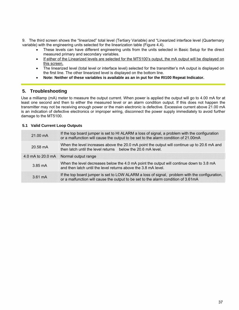
37
Use a milliamp (mA) meter to measure the output current. When power is applied the output will go to 4.00 mA for at least one second and then to either the measured level or an alarm condition output. If this does not happen the transmitter may not be receiving enough power or the main electronic is defective. Excessive current above 21.00 mA is an indication of defective electronics or improper wiring, disconnect the power supply immediately to avoid further damage to the MT5100.
5.1 Valid Current Loop Outputs
21.00 mA If the top board jumper is set to HI ALARM a loss of signal, a problem with the configuration or a malfunction will cause the output to be set to the alarm condition of 21.00mA
20.58 mA When the level increases above the 20.0 mA point the output will continue up to 20.6 mA and then latch until the level returns below the 20.6 mA level.
4.0 mA to 20.0 mA Normal output range
3.85 mA When the level decreases below the 4.0 mA point the output will continue down to 3.8 mA and then latch until the level returns above the 3.8 mA level.
3.61 mA If the top board jumper is set to LOW ALARM a loss of signal, problem with the configuration, or a malfunction will cause the output to be set to the alarm condition of 3.61mA
5. Troubleshooting
9. The third screen shows the “linearized” total level (Tertiary Variable) and “Linearized interface level (Quarternary variable) with the engineering units selected for the linearization table (Figure 4.4).
These levels can have different engineering units from the units selected in Basic Setup for the direct measured primary and secondary variables.
If either of the Linearized levels are selected for the MT5100’s output, the mA output will be displayed on this screen.
The linearized level (total level or interface level) selected for the transmitter’s mA output is displayed on the first line. The other linearized level is displayed on the bottom line.
Note: Neither of these variables is available as an in put for the RI100 Repeat Indicator.
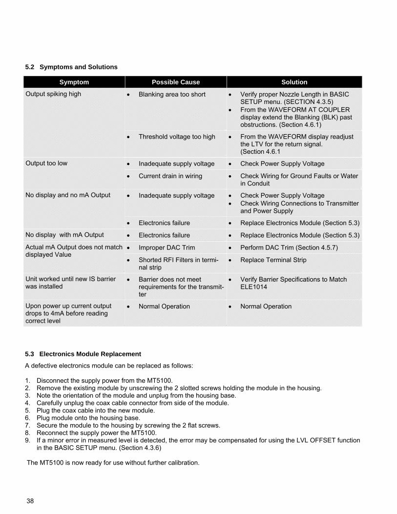
38
5.2 Symptoms and Solutions
Symptom Possible Cause Solution
Output spiking high Blanking area too short Verify proper Nozzle Length in BASIC SETUP menu. (SECTION 4.3.5)
From the WAVEFORM AT COUPLER display extend the Blanking (BLK) past obstructions. (Section 4.6.1)
Threshold voltage too high From the WAVEFORM display readjust the LTV for the return signal. (Section 4.6.1
Output too low Inadequate supply voltage Check Power Supply Voltage
Current drain in wiring Check Wiring for Ground Faults or Water in Conduit
No display and no mA Output Inadequate supply voltage Check Power Supply Voltage Check Wiring Connections to Transmitter
and Power Supply
Electronics failure Replace Electronics Module (Section 5.3)
No display with mA Output Electronics failure Replace Electronics Module (Section 5.3)
Improper DAC Trim Perform DAC Trim (Section 4.5.7)
Shorted RFI Filters in termi-nal strip
Replace Terminal Strip
Unit worked until new IS barrier was installed
Barrier does not meet requirements for the transmit-ter
Verify Barrier Specifications to Match ELE1014
Upon power up current output drops to 4mA before reading correct level
Normal Operation Normal Operation
Actual mA Output does not match displayed Value
A defective electronics module can be replaced as follows: 1. Disconnect the supply power from the MT5100. 2. Remove the existing module by unscrewing the 2 slotted screws holding the module in the housing. 3. Note the orientation of the module and unplug from the housing base. 4. Carefully unplug the coax cable connector from side of the module. 5. Plug the coax cable into the new module. 6. Plug module onto the housing base. 7. Secure the module to the housing by screwing the 2 flat screws. 8. Reconnect the supply power the MT5100. 9. If a minor error in measured level is detected, the error may be compensated for using the LVL OFFSET function
in the BASIC SETUP menu. (Section 4.3.6) The MT5100 is now ready for use without further calibration.
5.3 Electronics Module Replacement
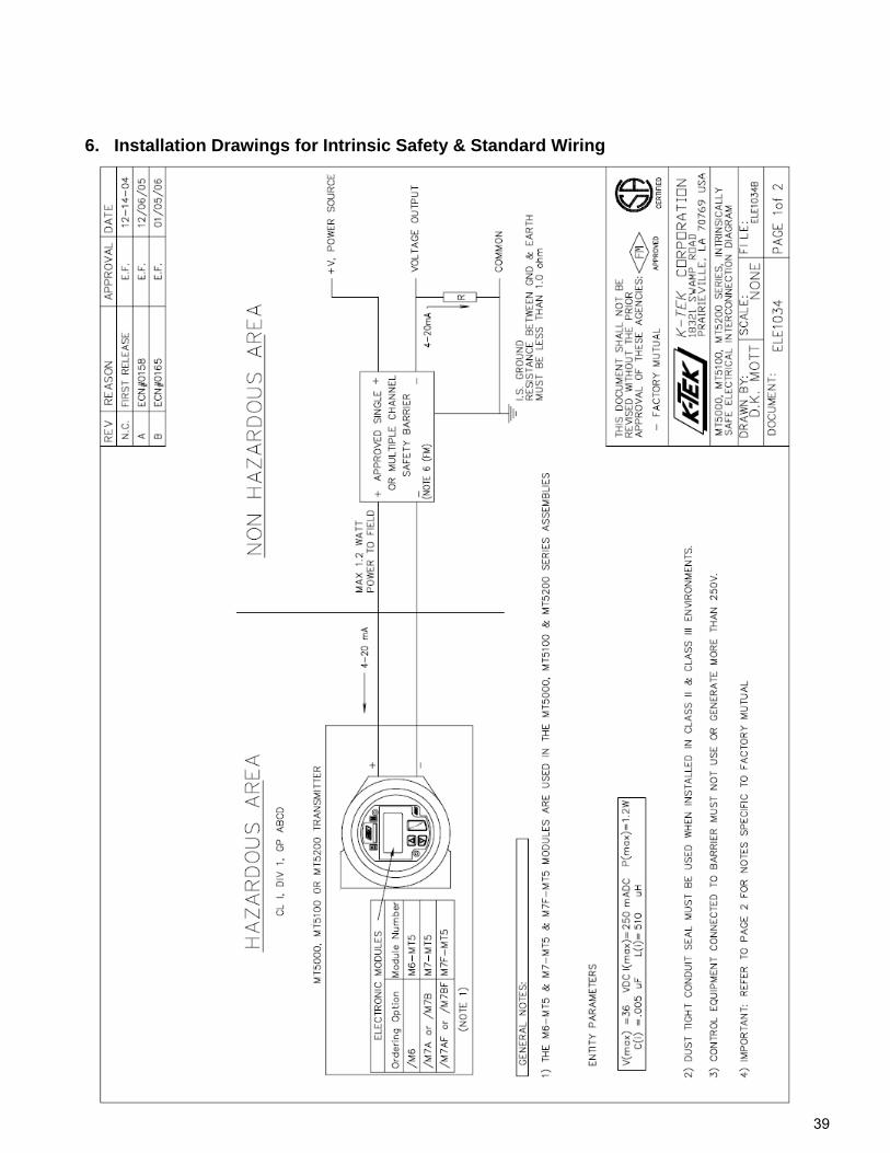
39
6. Installation Drawings for Intrinsic Safety & Standard Wiring
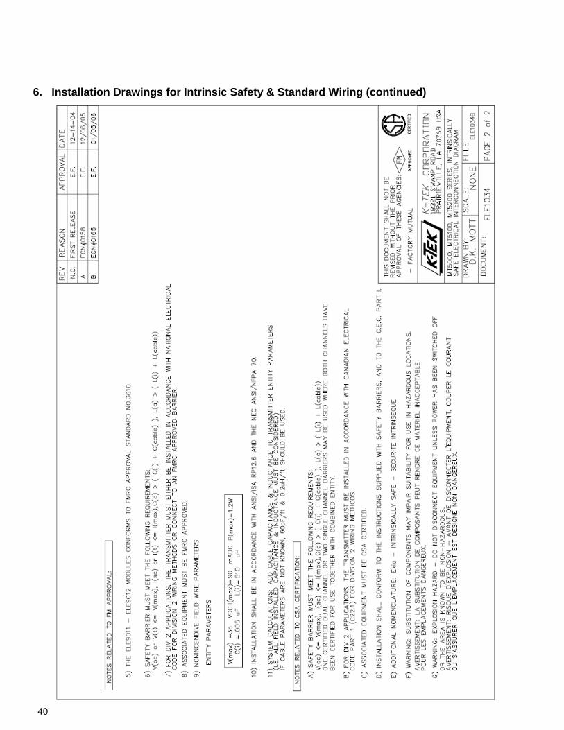
40
6. Installation Drawings for Intrinsic Safety & Standard Wiring (continued)
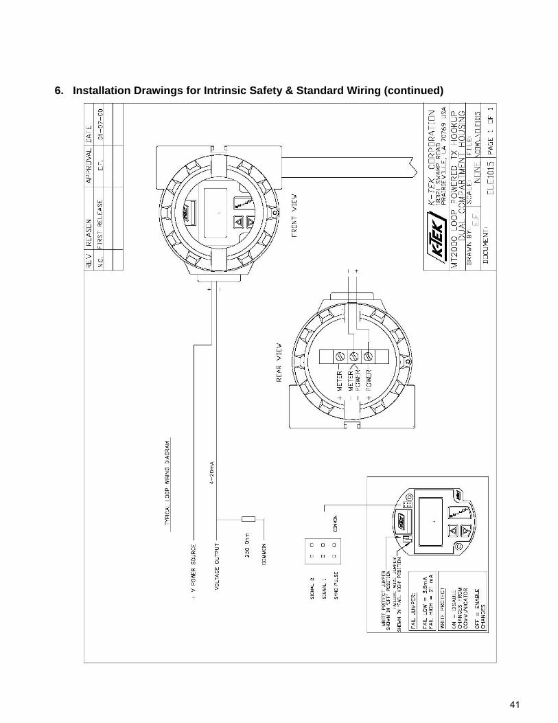
41
6. Installation Drawings for Intrinsic Safety & Standard Wiring (continued)
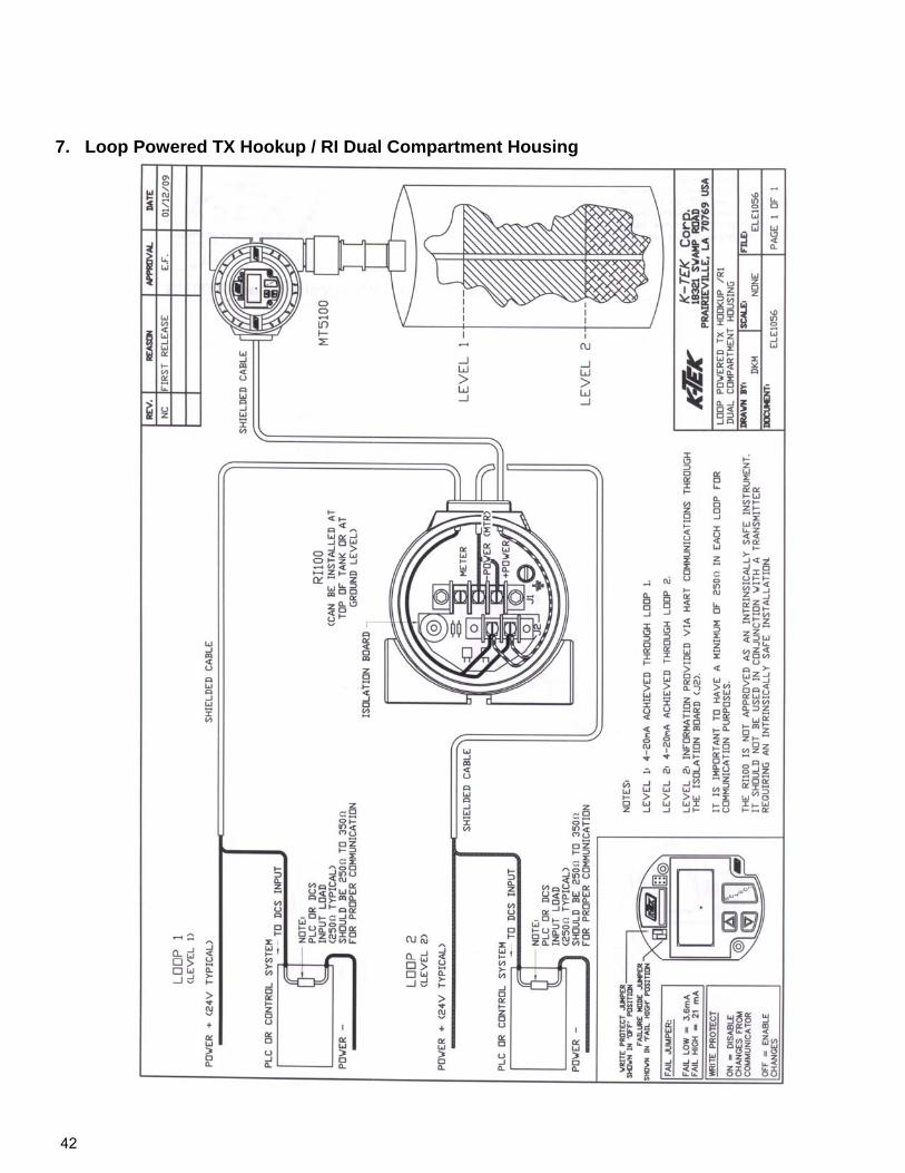
42
7. Loop Powered TX Hookup / RI Dual Compartment Housing
43
8. CE Certificate of Conformity
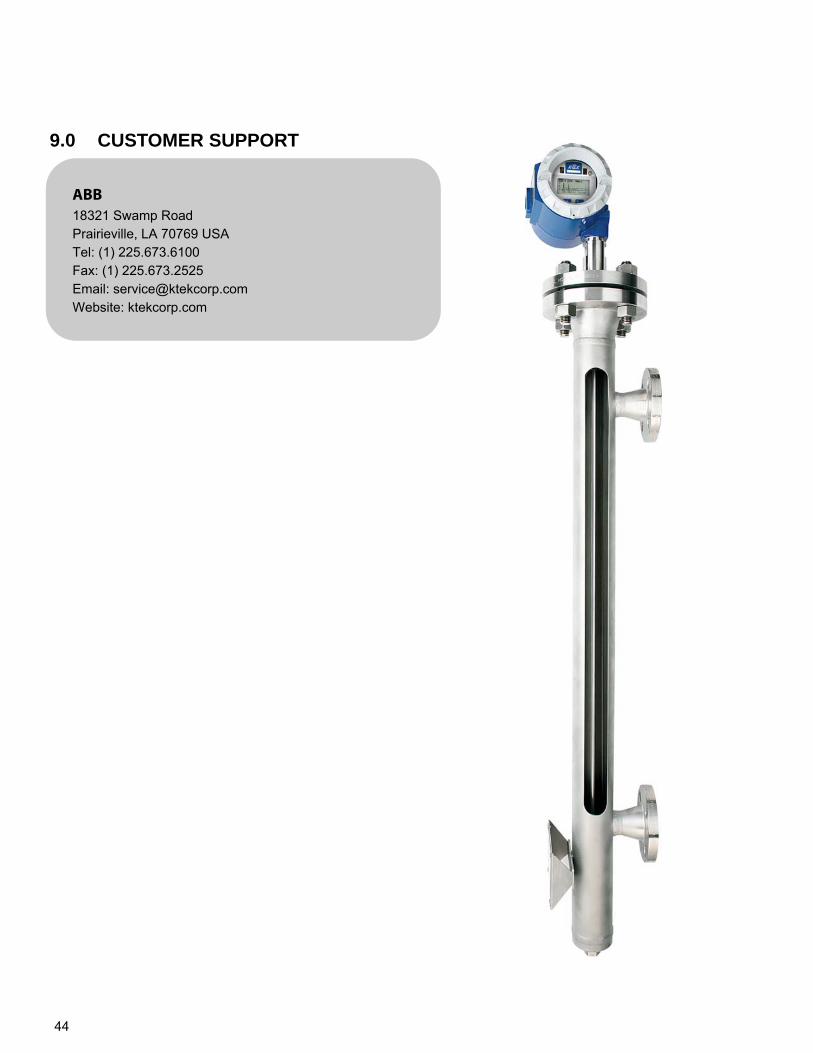
44
9.0 CUSTOMER SUPPORT
ABB 18321 Swamp Road Prairieville, LA 70769 USA Tel: (1) 225.673.6100 Fax: (1) 225.673.2525 Email: [email protected] Website: ktekcorp.com
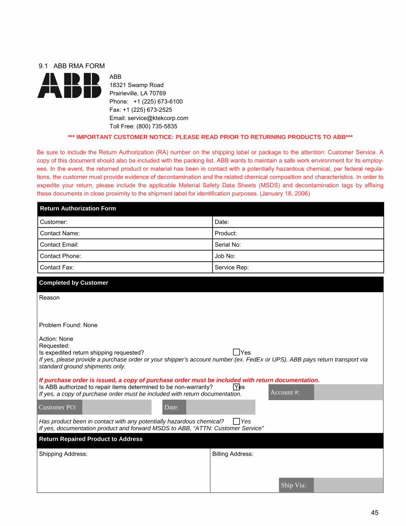
45
ABB 18321 Swamp Road Prairieville, LA 70769 Phone: +1 (225) 673-6100 Fax: +1 (225) 673-2525 Email: [email protected] Toll Free: (800) 735-5835
9.1 ABB RMA FORM
*** IMPORTANT CUSTOMER NOTICE: PLEASE READ PRIOR TO RETURNING PRODUCTS TO ABB*** Be sure to include the Return Authorization (RA) number on the shipping label or package to the attention: Customer Service. A copy of this document should also be included with the packing list. ABB wants to maintain a safe work environment for its employ-ees. In the event, the returned product or material has been in contact with a potentially hazardous chemical, per federal regula-tions, the customer must provide evidence of decontamination and the related chemical composition and characteristics. In order to expedite your return, please include the applicable Material Safety Data Sheets (MSDS) and decontamination tags by affixing these documents in close proximity to the shipment label for identification purposes. (January 18, 2006)
Return Authorization Form
Customer: Date: Contact Name: Product: Contact Email: Serial No: Contact Phone: Job No: Contact Fax: Service Rep:
Completed by Customer
Reason Problem Found: None Action: None Requested: Is expedited return shipping requested? Yes If yes, please provide a purchase order or your shipper’s account number (ex. FedEx or UPS). ABB pays return transport via standard ground shipments only. If purchase order is issued, a copy of purchase order must be included with return documentation. Is ABB authorized to repair items determined to be non-warranty? Yes If yes, a copy of purchase order must be included with return documentation. Has product been in contact with any potentially hazardous chemical? Yes If yes, documentation product and forward MSDS to ABB, “ATTN: Customer Service”
□
□ Customer PO:
Account #:
Date:
□ Return Repaired Product to Address
Shipping Address:
Billing Address:
Ship Via:
46
10. Warranty
5 YEAR WARRANTY FOR: KM26 Magnetic Liquid Level Gauges; MagWave Dual Chamber System; LS Series Mechanical Level Switches (LS500, LS550, LS600, LS700, LS800 & LS900) (does NOT include switching mechanisms, ie. MS30, MS40, MS41, PS35 & PS45); EC External Chambers, STW Stilling Wells and ST95 Seal Pots. 3 YEAR WARRANTY FOR: KCAP300 & KCAP400 capacitance switches. BETA Pressure and Temperature Switches have a limited factory guarantee, ex-cluding wetted parts & consumables. 2 YEAR WARRANTY FOR: AT100, AT100S and AT200 series transmitters; RS80 and RS85 liquid vibrating fork switches; RLT100 and RLT200 reed switch level transmitters; TX, TS, TQ, IX and IM thermal dispersion switches; IR10 and PP10 External Relays; MT2000, MT5000, MT5100 and MT5200 radar level transmitters; RI100 Repeat Indicators; KP paddle switches; A02, A75 & A77 RF capacitance level switches and A38 RF capacitance level transmitters; Buoyancy Level Switches (MS50, MS10, MS8D & MS8F); Magnetic Level Switches (MS30, MS40, MS41, PS35 & PS45). 1 YEAR WARRANTY FOR: KM50 gauging device; AT500 and AT600 series transmitters; LaserMeter and SureShot series laser transmitters; LPM200 digital indicator; DPM100 digital indicators; APM100 analog indicators; KVIEW series digital indicators and controllers; GRANUPOINT and SLUDGEPOINT vibrating fork switches, SOLITRAK Electro-Mechanical Continuous Measuring Devices, KSONIK ultrasonic level switches, transmitters & transducers, ChuteMaster Microwave Transmitter / Receiver and TiltMaster Switches. SPECIAL WARRANTY CONSIDERATIONS: ABB does not honor OEM warranties for items not manufactured by ABB (i.e. Palm Pilots). These claims should be handled di-rectly with the OEM. ABB will repair or replace, at ABB’s election, defective items which are returned to ABB by the original purchaser within the period specified above from the shipment date of the item and which is found, upon examination by ABB, to its satisfaction, to contain defects in materials or workmanship which arose only under normal use and service and which were not the result of either al-terations, misuse, abuse, improper or inadequate adjustments, applications or servicing of the product. ABB’s warranty does not cover the repair or replacement of units that fail from the effects of excessive vibration unless the units are originally designed for vibration application. In addition, ABB’s warranty does not include on-site repair or services. Field service rates can be sup-plied on request. If a product is believed to be defective, the original purchaser shall notify ABB and request a Returned Material Authorization be-fore returning the material to ABB, with transportation prepaid by the purchaser. (To expedite all returns/repairs from outside of the United States, consult ABB’s customer service team ([email protected]) to determine an optimal solution for shipping method and turnaround time.) The product, with repaired or replaced parts, shall be returned to the purchaser at any point in the world with transportation prepaid by ABB for best-way transportation only. ABB is not responsible for expedited shipping charges. If the product is shipped to ABB freight collect, then it will be returned to the customer freight collect. If inspection by ABB does not disclose any defects in material or workmanship, ABB’s normal charges for repair and shipment shall apply (minimum 250.00 USD). The materials of construction for all ABB products are clearly specified and it is the responsibility of the purchaser to determine the compatibility of the materials for the application. THE FOREGOING WARRANTY IS ABB'S SOLE WARRANTY AND ALL OTHER WARRANTIES EXPRESSED, IMPLIED, OR STATUTORY, INCLUDING ANY IMPLIED WARRANTY OF MERCHANTABILITY OF FITNESS FOR A PARTICULAR PUR-POSE, ARE EXCLUDED AND NEGATED TO THE MAXIMUM EXTENT PERMITTED BY LAW. NO PERSON OR REPRESEN-TATIVE IS AUTHORIZED TO EXTEND ANY OTHER WARRANTY OR CREATE FOR ABB ANY OTHER LIABILITY IN CON-NECTION WITH THE SALE OF ABB’S PRODUCTS. THE REMEDIES SET FORTH IN THIS WARRANTY ARE EXCLUSIVE OF ALL OTHER REMEDIES AGAINST ABB. ABB SHALL NOT BE LIABLE FOR ANY CONSEQUENTIAL, INCIDENTAL, OR SPE-CIAL DAMAGES OF ANY KIND. ABB’S SOLE OBLIGATION SHALL BE TO REPAIR OR REPLACE PARTS (FOUND TO BE DEFECTIVE IN MATERIALS OR WORKMANSHIP) WHICH ARE RETURNED BY THE PURCHASER TO ABB.

47
48
Contact us
ABB US 18321 Swamp Road Prairieville, LA 70769 USA Tel: +1 225 673 6100 Fax: +1 225 637 2525 www.abb.com/level
Note We reserve the right to make technical changes or modify the contents of this document without prior notice. With regard to purchase orders, the agreed particulars shall prevail. ABB does not accept any responsibility whatsoever for potential errors or possible lack of information in this document. We reserve all rights in this document and in the subject matter and illustrations contained therein. Any reproduction, disclosure to third parties or utilization of its contents - in whole or in parts – is forbidden without prior written consent of ABB. Copyright© 2011 ABB All rights reserved
OI/M
T510
0-E
N R
ev. B
0
5.20
12