Embed Size (px)
Citation preview

Operating, Field Maintenance,and Parts Manual
Model998
General Safety PrecautionsNever point the gun at anyone.Inspect hose before each use for breaks or weakened spots.Always shut off valve at tank when leaving the gun unattended for any length of time.WARNING: DO NOT TOUCH WIRE METAL SHIELD AFTER GUN HAS BEEN FIRED.
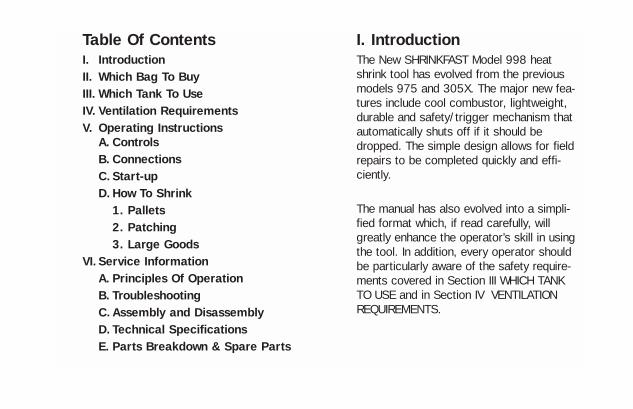
Table Of ContentsI. IntroductionII. Which Bag To BuyIII. Which Tank To UseIV. Ventilation RequirementsV. Operating Instructions
A. ControlsB. ConnectionsC. Start-upD. How To Shrink
1. Pallets2. Patching3. Large Goods
VI. Service InformationA. Principles Of OperationB. TroubleshootingC. Assembly and DisassemblyD. Technical SpecificationsE. Parts Breakdown & Spare Parts
I. IntroductionThe New SHRINKFAST Model 998 heatshrink tool has evolved from the previousmodels 975 and 305X. The major new fea-tures include cool combustor, lightweight,durable and safety/trigger mechanism thatautomatically shuts off if it should bedropped. The simple design allows for fieldrepairs to be completed quickly and effi-ciently.
The manual has also evolved into a simpli-fied format which, if read carefully, willgreatly enhance the operator’s skill in usingthe tool. In addition, every operator shouldbe particularly aware of the safety require-ments covered in Section III WHICH TANKTO USE and in Section IV VENTILATIONREQUIREMENTS.
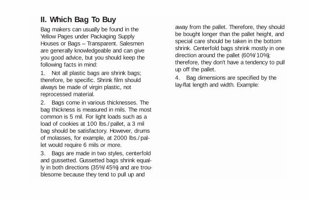
II. Which Bag To BuyBag makers can usually be found in theYellow Pages under Packaging SupplyHouses or Bags – Transparent. Salesmenare generally knowledgeable and can giveyou good advice, but you should keep thefollowing facts in mind:1. Not all plastic bags are shrink bags;therefore, be specific. Shrink film shouldalways be made of virgin plastic, notreprocessed material.2. Bags come in various thicknesses. Thebag thickness is measured in mils. The mostcommon is 5 mil. For light loads such as aload of cookies at 100 lbs./pallet, a 3 milbag should be satisfactory. However, drumsof molasses, for example, at 2000 lbs./pal-let would require 6 mils or more.3. Bags are made in two styles, centerfoldand gussetted. Gussetted bags shrink equal-ly in both directions (35%/45%) and are trou-blesome because they tend to pull up and
away from the pallet. Therefore, they shouldbe bought longer than the pallet height, andspecial care should be taken in the bottomshrink. Centerfold bags shrink mostly in onedirection around the pallet (60%/10%);therefore, they don’t have a tendency to pullup off the pallet.4. Bag dimensions are specified by thelay-flat length and width. Example:

To calculate the width, add:
1. The two sides 30”47”77”
2. Fitting allowance 4”
WIDTH 81”
To calculate the length, add:1. 1/2 of the short side 15”2. The height 36”3. Shrink allowance –1” for each foot of height 3”
LENGTH 54”
In this case the bag size is 81” x 54”.

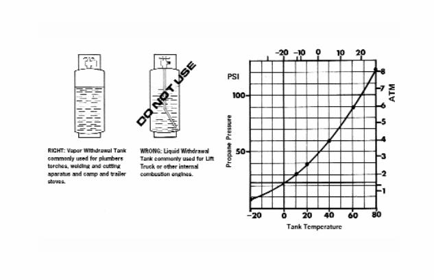
III. Which Tank To UseTwo types of tanks are commonly available:liquid withdrawal and vapor withdrawal. It iscrucial to use the vapor withdrawal type.Never try to run the gun on a liquid with-drawal tank.Using a liquid withdrawal tank will clog theorifice filter and may result in an extremelydangerous long flame.Tanks are available in 6, 8, 10, 20, 30, and40 lb. Sizes. The gun will run on a 6 lb.Tank if used only intermittently. Larger tanksshould be chosen for continuous use.Tank pressure depends on the temperatureof the tank. At room temperature (72°F) thepressure is 110 PSI and drops to 22 PSI at0°F.When in use, the temperature of the tankdrops due to the evaporation process of liq-uid propane to propane gas.After prolonged use the temperature of the
tank may drop to 0°F usually accompaniedby icing on the outside, and the propanepressure drops below 15 PSI. DO NOT RUNTHE GUN WITH THE PRESSURE BELOW 15PSI.Small or nearly empty tanks ice up fasterthan large, full tanks. Typically, a full 30 lb.Tank , if run continuously, will run 90 min-utes before it ices up. If the productionrates demand continuous use, the followingmethods may be employed:1. Multiple tanks. Switch the gun from onetank to another.2. Fan. An ordinary desk Fan fan at thetank. The air flow around the tank will keepit from icing up.
IV. Ventilation Requirements
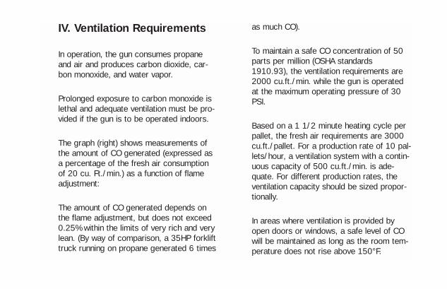
In operation, the gun consumes propaneand air and produces carbon dioxide, car-bon monoxide, and water vapor.
Prolonged exposure to carbon monoxide islethal and adequate ventilation must be pro-vided if the gun is to be operated indoors.
The graph (right) shows measurements ofthe amount of CO generated (expressed asa percentage of the fresh air consumptionof 20 cu. Ft./min.) as a function of flameadjustment:
The amount of CO generated depends onthe flame adjustment, but does not exceed0.25% within the limits of very rich and verylean. (By way of comparison, a 35HP forklifttruck running on propane generated 6 times
as much CO).
To maintain a safe CO concentration of 50parts per million (OSHA standards1910.93), the ventilation requirements are2000 cu.ft./min. while the gun is operatedat the maximum operating pressure of 30PSI.
Based on a 1 1/2 minute heating cycle perpallet, the fresh air requirements are 3000cu.ft./pallet. For a production rate of 10 pal-lets/hour, a ventilation system with a contin-uous capacity of 500 cu.ft./min. is ade-quate. For different production rates, theventilation capacity should be sized propor-tionally.
In areas where ventilation is provided byopen doors or windows, a safe level of COwill be maintained as long as the room tem-perature does not rise above 150°F.

V. Operating Instructions
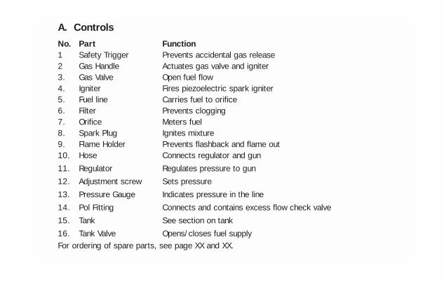
A. ControlsNo. Part Function1 Safety Trigger Prevents accidental gas release2 Gas Handle Actuates gas valve and igniter3. Gas Valve Open fuel flow4. Igniter Fires piezoelectric spark igniter5. Fuel line Carries fuel to orifice6. Filter Prevents clogging7. Orifice Meters fuel8. Spark Plug Ignites mixture9. Flame Holder Prevents flashback and flame out10. Hose Connects regulator and gun11. Regulator Regulates pressure to gun12. Adjustment screw Sets pressure13. Pressure Gauge Indicates pressure in the line14. Pol Fitting Connects and contains excess flow check valve15. Tank See section on tank16. Tank Valve Opens/closes fuel supplyFor ordering of spare parts, see page XX and XX.

B. ConnectionsConnect the gun, hose and regulator to thetank using a wrench to tighten the fittingswhich all have left hand threads.To check for leaks, open the tank valve with-out actuating the gun handle to pressurizethe hose. The pressure gauge should readbetween 15 and 30 PSI when the gun is notin use. Then close the tank valve andobserve the pressure gauge. A rapid loss ofpressure indicates a leak. Check all connec-tions.
C. Start-UpAfter all connections are made and checkedfor leaks, the gun is ready for use. Open thetank valve. Wait approximately 5 seconds tofully pressurize the hose or until the excessflow check valve opens with an audible click.To start the gun, first press the safety trig-ger which prevents the gas handle frombeing accidentally opened. Then squeeze
the gas handle slowly all the way until theigniter fires with an audible click. CAUTION,GUN WILL IGNITE.
NOTES:1. It is important to squeeze the gas han-dle slowly. If the gas handle is squeezed tooquickly, the igniter will fire the spark plugbefore the gas mixture gets there.2. Should the gun fail to fire fully, releaseboth safety trigger and gas handle fully toassure that the igniter is reset and repeatthe starting procedure.3. The 998 heat tool comes complete witha variable regulator assembly. The tool willoperate properly between 15 and 30 PSI.For thinner films, we recommend the settingto be on the low pressure side and adjust upto the 30 PSI level as the films get thicker.The factory setting is preset at 22 PSI.

D. How to Shrink1. PalletizingYour SHRINKFAST gun consumes oxygenand must be used only in well ventilatedareas. WARNING: DO NOT OPERATE GUN INAREAS WITH FLAMMABLE GASES ORWHERE SMOKING IS PROHIBITED.
a. Elevate the pallet load approximately 6 inches from the floor, leaving the under sides of the four corners unobstructed.b. Fit the pallet bag over the load, taking care that the film is not punctured as it is pulled into place. The bag should fit snuglyover the goods and overhand the base of the pallet almost to the floor.c. To bottom shrink, ignite the gun and hold it approximately 12” from the film surface. Move once around the pallet apply-ing heat to the bottom edge of the bag and using the air velocity to blow it under
the pallet. Shrink it so that it grasps the underside of the pallet firmly. In so doing, the bag is locked to the pallet, thereby uni-tizing the load.d. To side shrink, do one side after anoth-er. Hold the gun approximately 12” from the film surface; shrink the side by sweep-ing the gun smoothly across the bottom. Move up a foot and sweep back and con-tinue sweeping across the face moving upwith every sweep until the side is finished. You will see the film wrinkling ahead of thegun as the film behind commences to shrink. It is important that the gun be keptin motion at all times. The action is very similar to spray painting.As one side is completed, move to the next, each time commencing at the bottom and working your way up as you sweep from side to side.e. The top of the pallet is shrunk last and requires less heat than the sides. This is
due to it already having been pulled tautthrough shrinkage of the four sides.f. The pallet is now ready for shipment. Lifttruck forks may be driven through the filmwhere it covers the wooden pallet; the punc-tures will not propagate.NOTES:The most important fact to keep in mind isthat heat only softens the film. The greatestamount of shrinking occurs as the filmcools. It is a common fault of the inexperi-enced operator to apply too much heat tothe film often concentrating the heat andwaiting for the film to shrink before movingthe gun.Keep the gun moving.With a little practice, you will find you canhold the gun closer to the film and sweepfaster often shrinking a pallet in less than 2minutes.It is absolutely necessary that the four cor-ners of the bag be caught under the pallet.
If this is not done, the effectiveness ofshrink palletizing is considerably reduced.2. PatchingOccasionally, holes will appear in the film.These may be easily patched by laying asquare of film over the hole and applyingheat around the edges welding the patch tothe bag. The same technique may beapplied to reinforce edges or corners withpatches.3. Shrink Wrapping Large Or OddShaped LoadsShrink wrapping is a versatile method whichmay be employed in a great variety of appli-cations. For example, shrink wrappers rou-tinely wrap irregular objects such as canoesusing sheets of shrink film.Objects which are too big to fit under a bagmay be wrapped by using several sheets ofshrink film joined together if the followingtwo precautions are observed:
Adjoining sheets should have an 18” over-lap. This overlapping allows the sheets toweld together during the shrink process.The sheets must be secured at the base ofthe load using the weight of the load or bybattens tacked to the skids or any othermethod that may be expedient.NOTE: SHEETS SHOULD BE JOINEDTOGETHER ON THE FLOOR WITH AN 18”OVERLAP.
IV. Service InformationNote: Letters Keyed To Text On FollowingPages.

A. Principles Of OperationThe SHRINKFAST 998 introduces a signifi-cantly improved jet pump based on using amultiple nozzle orifice (patents pending). Thejet pump is shorter and more efficient withthe benefits of a wider and more powerfulheat pattern. Like the Model 975, it is basi-cally a simple jet engine, the high energyexhaust of which is used to pump and heatthe surrounding air and deliver an air blastof high velocity and moderate temperature.Its effectiveness is based on the high levelof technical development which has goneinto optimizing each stage of operation:1. Jet Pump. The propane jet (A) draws thecorrect amount of combustion air throughthe air inlet (B). They mix together in thestraight section (C).2. Compression. The conical section (D)turns speed into pressure.3. Combustion. The combustion process iscarried out inside the combustor (E). The
flame holder (F) prevents flashback (wherethe flame travels back into the jet pump)and the flame out (where the flame is blownout of the combustor). Another proprietaryfunction of the flame holder is to achieve theunusual effect of maintaining cold combus-tor walls in spite of the fact that the com-bustion is substantially completed inside thecombustor. This it does by imparting a swirlto the mixture. During combustion, theburned portion of the mixture expands, andits density diminishes. The swirl centrifugesthe unburned, heavier portion outward andthereby creating a blanket of cold mixturealong the walls. As combustion proceeds,the process draws from the protective layerof unburned mixture, and when combustionis completed the cooling effect stops. Thesize of the combustor ensures that for ratedflow the point of completion coincides withthe outlet. At less than rated flow, the blan-ket of unburned mixture does not extend allthe way to the outlet and results in a red hot
combustor outlet.4. Expansion. By virtue of the internal com-bustion process at elevated pressure a por-tion of the heat energy is converted toexhaust gas velocity. The gasses areexpanded into the atmosphere through thecombustor (E) with a velocity of over 160MPH and a noticeable amount of thrust.5. Entrainment. A second jet pump effectis created by the exhaust gases as theyleave the combustor. The slot shaped outletof the combustor creates a large mixtureinterface and promotes high volume entrain-ment within an unusually short distance. Theexhaust gases transfer their heat andmomentum to the entrained air and thus cre-ate a stream of high volume, low tempera-ture air. This pumping effect is progressive,i.e. as the distance from the combustorincreases so does the volume of airentrained. Since the heat and momentumare distributed over all the entrained air, the
temperature and velocity of the outputdecrease as a function of distance awayfrom the gun.
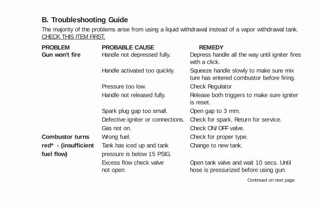
B. Troubleshooting GuideThe majority of the problems arise from using a liquid withdrawal instead of a vapor withdrawal tank.CHECK THIS ITEM FIRST.
PROBLEM PROBABLE CAUSE REMEDYGun won’t fire Handle not depressed fully. Depress handle all the way until igniter fires
with a click.Handle activated too quickly. Squeeze handle slowly to make sure mix
ture has entered combustor before firing.Pressure too low. Check RegulatorHandle not released fully. Release both triggers to make sure igniter
is reset.Spark plug gap too small. Open gap to 3 mm.Defective igniter or connections. Check for spark. Return for service.Gas not on. Check ON/OFF valve.
Combustor turns Wrong fuel. Check for proper type.red* - (insufficient Tank has iced up and tank Change to new tank.fuel flow) pressure is below 15 PSIG.
Excess flow check valve Open tank valve and wait 10 secs. Until not open. hose is pressurized before using gun.
Continued on next page
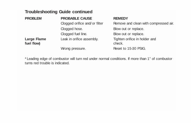
Troubleshooting Guide continuedPROBLEM PROBABLE CAUSE REMEDY
Clogged orifice and/or filter Remove and clean with compressed air.Clogged hose. Blow out or replace.Clogged fuel line. Blow out or replace.
Large Flame Leak in orifice assembly. Tighten orifice in holder and fuel flow) check.
Wrong pressure. Reset to 15-30 PSIG.
*Leading edge of combustor will turn red under normal conditions. If more than 1” of combustorturns red trouble is indicated.

C. Assembly & DisassemblyGENERAL NOTES1. Grease all “O” rings to facilitate assem-bly.2. Fitting (23) is glued permanently intothe valve body (22). 1. Filter Cleaning1.1 Unscrew filter holder (1) using a screwdriver or a coin. Pull out the filter holder.
1.2 Pull out the filter screen/spring assem-bly (3,4) and clean with compressed air orreplace.
2. Spark Plug Replacement2.1 Depress button (31) and remove com-bustor assembly (30)
2.2 Pull spark plug (28) and flame holder(32) out with a pair of pliers.

2.3 Unscrew spark plug. Note: spark pluggap should be set to 3-5mm.3. Igniter Replacement
3.1 Undo the 5 mounting screws (29) andremove right housing (15).
3.2 Undo contact screw (25) which retainsthe cable (17,18) and the contact spring(26)
3.3 Snap off the clamp (34) with a screwdriver.
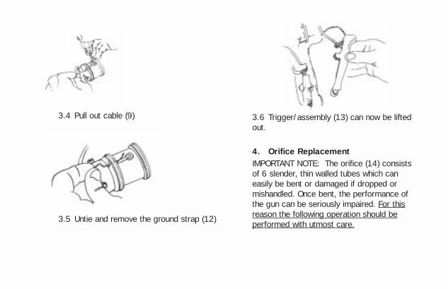
3.4 Pull out cable (9)
3.5 Untie and remove the ground strap (12)
3.6 Trigger/assembly (13) can now be liftedout.
4. Orifice ReplacementIMPORTANT NOTE: The orifice (14) consistsof 6 slender, thin walled tubes which caneasily be bent or damaged if dropped ormishandled. Once bent, the performance ofthe gun can be seriously impaired. For thisreason the following operation should beperformed with utmost care.
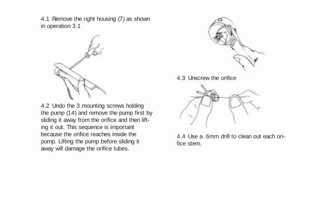
4.1 Remove the right housing (7) as shownin operation 3.1
4.2 Undo the 3 mounting screws holdingthe pump (14) and remove the pump first bysliding it away from the orifice and then lift-ing it out. This sequence is importantbecause the orifice reaches inside thepump. Lifting the pump before sliding itaway will damage the orifice tubes.
4.3 Unscrew the orifice
4.4 Use a .6mm drill to clean out each ori-fice stem.

UL Gun Only5. Safety Cage Mounting
5.1 Push both curved tubular joines (15)onto one half of the cage (16).
5.2 Insert the second half of the cage (17)into the tubular joints and twist it together
fully until the mounting struts of both halvesare parallel.
5.3 Attach the cage assembly to the com-bustor with the 4 mounting screws (18).
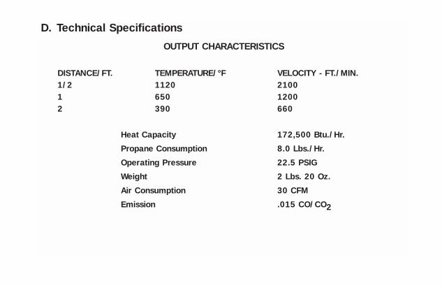
D. Technical SpecificationsOUTPUT CHARACTERISTICS
DISTANCE/FT. TEMPERATURE/°F VELOCITY - FT./MIN.1/2 1120 21001 650 12002 390 660
Heat Capacity 172,500 Btu./Hr.
Propane Consumption 8.0 Lbs./Hr.
Operating Pressure 22.5 PSIG
Weight 2 Lbs. 20 Oz.
Air Consumption 30 CFM
Emission .015 CO/CO2
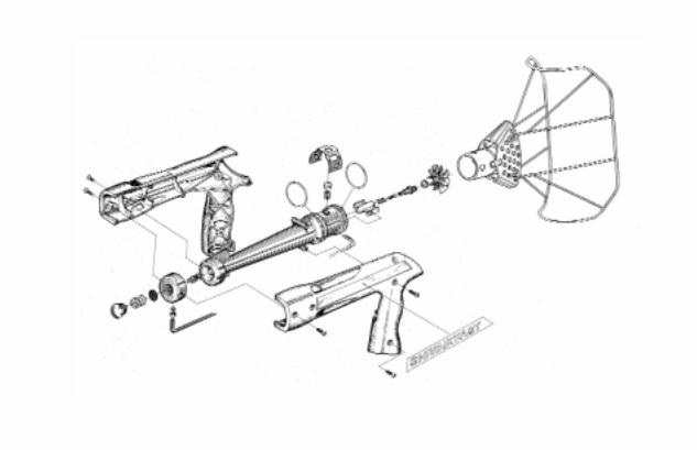

1. Filter Holder2. O ring3. Filter (disc)4. Filter Spring5. Orifice Assy.6. 24-O ring7. Retainer8. Inlet9. Fuel Line10. Pump Body11. Label, RH12. Label, LH13. Name Plate, UL (Not shown)14. Name Plate, Euro (Not shown)15. Housing, RH16. Housing, LH17. Trigger/Igniter Assy18. Trigger/Igniter Assy20. Safety21. Spring22. Valve Assy23A. Hose Adapter-US23B. Hose Adapter-Met.
25. Contact Screw26. Contact Spring27. Socket28. Spark Plug29. Assy Screws30. Combustor31. Button32. Flameholder33. O ring34. Strap35. Button Spring36A. Hose Assy-US (Not shown)36B. Hose Assy-Metric (Not shown)37. Regulator Assy-US (Not shown)37 Regulator Assy-Metric (Not shown)37. Regulator Assy-Nul40. Metal Box (Not shown)41. Guard Screw43A. UL Guard43B. Euro Guard44A. Wrench-US (Not shown)44B. Wrench-Euro (Not shown)


![6ES5 998-0UF23[1]](https://img.pdfslide.us/doc/110x75/544f5260b1af9f23638b5792/6es5-998-0uf231.jpg)


![Productivity in Mining[998]](https://img.pdfslide.us/doc/110x75/58859f151a28abd2498b6925/productivity-in-mining998.jpg)