Embed Size (px)
Citation preview

This manual contains important maintenance procedures for the continued proper operation of your unit. These MUST be performed regularly for your guarantee to remain valid.
Residential Scaleless SystemModel # SL948-10-5600, SL1054-12-5600, SL1252-16-7000
Operating and Maintenance Manual
54993WG.0212

1
How Your Scaleless Stack Water Filter WorksWater Enters through the inlet of the control valave passes through the media bed (Activated Carbon) contained in the mineral tank. This reduces the chlorine content of your municipally supplied water and reduces taste and odor of the water. The water then passes through the stack distributor where a scaleless media and goes through the outlet of the control valve to the house.The Scaleless system provides protection from scale formation throughout the home. The Scaleless system can be installed at the point of entry to treat your entire home, both hot and cold water, or it can be located directly before a water heater or other device (e.g. sauna, etc) that requires protection from hard water. Scaleless reduces or eliminates scale formation on internal and external plumbing surfaces as well as reducing spotting and streaking normally associated with hard water.Scaleless prevents scale by transforming the normal dissolved hardness minerals into undissolved crystal micro-particles. These crystals stay suspended in the water and have a greatly reduced ability to react and attach to surfaces like dissolved hardness does. Therefore the problem of internal buildup of scale in pipes, water heat-ers and on fixtures and glass is greatly reduced. Scaleless is not a water softener – Low or phosphate-free cleaning products are recommended to achieve opti-mum results. Modern surfactant or detergent based, liquid soaps are preferred over oldfashioned caustic solid soaps.Unlike softened water, Scaleless treated water maintains the beneficial essential mineral content of your water and is safe to drink.
Scaleless Benefits• Chemical Free Scale Prevention. Cost savings and environmental benefits.• Virtually Maintenance Free. No salt bags or other chemicals to buy, transport and store.• No Electricity, no wastewater, completely self-contained.• Beneficial minerals retained for more healthful drinking water.• Improves the efficiency of water-using appliances.• Simple installation – no electrical and drain hookup• Safe for landscaping and lawn watering. No need to costly bypass plumbing• Compatible with all on-site and community wastewater treatment systems• Not subject to water softener restrictions and “bans
Specification
Item # Model # Tank Control
ValveActivated Carbon
Flow Rate
(GPM)
Back-wash (GPM)
Frequency of Replace-
ment of Sca-less Stack
Connections I/O
Replacment Stack
Distributor item #
7960 SL948- 10-5600 9 x 48 5600SXT 1 CF 10 4 3 years 3/4” 33506
7961 SL1054- 12-5600 10 x 54 5600SXT 1.5 CF 12 5 3 years 3/4” 33507
7962 SL1252- 16-7000 12 x 52 7000SXT 2 CF 16 7 3 years 1” 33508
• Media and scale reduction distributor stack is recommended to be replaced every three years • Scale Media operates in upflow condition• These systems does not have a grain removal capacity, however, other contiminants present in the water will gradually degrade the effectiveness of this cartridge. • It is recommended to change the media altleast once a year• Temperature Range: 35 Deg F/2 Deg C to 100 deg F/30 Deg C• Maximum Pressure: 125 psi/8.6 bar• Do not use where water is microbiologically unsafe without adequately treating the water before or after the system • The manufacturer reserves the right to make product improvements which may deviate from the specifications and descriptions stated herein, without
obligation to change previously manufactured products or to note the change.• At the stated service flow rates, the pressure drop through these devices will not exceed 15 psig.

2
In normal operation, the Time of Day display will alternate being viewed with the Days Remaining Display the day Volume Remaining display will count down from a maximum value to zero or (---). Once this occurs, a regeneration cycle will be initiated at the Set Regeneration Time.
Example 3 days remaining for filter to regenerate
0 days Remaining to Regeneration
Control Operation During RegenerationIn regeneration, the control will display a special regeneration display. In this display, the control will show the current regeneration step number the valve is advancing to or has reached and the time remaining in that step. The step number displayed will flash until the valve has completed driving into this regeneration step position. Once all regeneration steps have been completed, the valve will return to Service and resume normal operation.
Example Less than 6 minutes remaining in Regen Step Rapid Rinse
Pushing the Extra Cycle Button during a regeneration cycle will immediately advance the valve to the next cycle step position and resume normal step timing.
Control Operation During ProgrammingThe control will only enter the Program Mode with the valve in Service. While in the Program Mode, the control will continue to operate normally, monitoring water usage and keeping all displays up to date. Control programming is stored in memory permanently, eliminating the need for battery back-up power.
Time Clock Delayed ControlA Time Clock Delayed Control regenerates the system on a timed interval. The control will initiate a regeneration cycle at the programmed regeneration time when the number of days since the last regeneration equals the regeneration day override value.
5
PM Indicator
PM Indicator
Flow Indicator(Flashing with water flow)
Flow Indicator(Flashing with water flow)
Riser Tube To fit between the con-trol valve and Scaleless Stack Distributor
Scaleless Stack
Media eg Granular Activated Carbon
Underbed
Startup Procedure1. Manually Generate the Control Valve to
Backwash model2. Turn on the water supply slowly to only
half way and let the tank fill with water for 10 minutes
3. Turn off the main water supply and wait for 3 minutes
4. Turn on the main water supply slowly to fully open and backwash for 30 minutes
5. Put unit to Rapid Rinse for 5 minutes.6. Unit is ready to use.
Scaleless Stack Distributor
Riser Tube
Control Valve
Scaleless Stack part #
Model # Part #SL948-10-5600 33506
SL1054-12-5600 33507
SL1252-16-7000 33508
The scaleless stack is recommended to be replaced every three years.

3
Installation InstructionsAll government codes and regulations governing the installation of these devices must be observed.
CAUTION: If the ground from the electrical panel or breaker box to the water meter or underground copper pipe is tied to the copper water lines and these lines are cut during installation of the Noryl bypass valve and/or poly pipe, an approved grounding strap must be used between the two lines that have been cut in order to maintain continuity. The length of the grounding strap will depend upon the number of units being installed and/or the amount of copper pipe being replaced with poly. See Figure 1.
In all cases where metal pipe was originally used and is later interrupted by poly pipe or the Noryl bypass valve as in Figure 1 or by physical separation as in Figure 2, an approved ground clamp with no less than #6 copper conductor must be used for continuity, to maintain proper metallic pipe bonding.
Check your local electrical code for the correct clamp and cable size.
1. Determine the best location for your water filter, bearing in mind the location of your water supply lines, drain line and 120 volt AC electrical outlet. Subjecting the filter to freezing or temperatures above 43°C (110°F) will void the warranty.
Media Installation (When Necessary)• For installation of stack distributor, remove the old
scaleless stack/ or conventional distributor tube from the tank after removing the media from the tank. Install the new Scaleless stack (come complete with lower basket and distibutor tube). Cut grey distributor tube so that the scaleless stack and control valve fits in the tank.
• Remove the valve from the mineral tank.• Temporarily plug the open end of the riser tube to ensure
that no resin or gravel falls down into the distribution.• Fill mineral tank one quarter full of water to protect
distribution during gravel installation.
Figure 1Electrical Panel
Ground Strap
Poly PipeGround From Panel
Poly Pipe
Filterc/w Plastic Bypass
Copper Pipe
Water Meter
Figure 2
Outside Water Line For Outside & 3rd Tap Comes From Meter
Filtered Water Line in Home
Unfiltered Water BypassLoop Cut & Capped
Ground Strap Required Because of Break in Continuity
Day of the Week ControlThis control regenerates the system on a weekly schedule. The schedule is defined in Master Programming by setting each day to either “off” or “on.” The control will initiates a regeneration cycle on days that have been set to “on” at the specified regeneration time.
Control Operation During a Power FailureThe SXT includes integral power backup. In the event of power failure, the control shifts into a power-saving mode. The control stops monitoring water usage, and the display and motor shut down, but it continues to keep track of the time and day for a minimum of 48 hours.The system configuration settings are stored in a non-volatile memory and are stored indefinitely with or without line power. The Time of Day flashes when there has been a power failure. Press any button to stop the Time of Day from flashing.If power fails while the unit is in regeneration, the control will save the current valve position before it shuts down. When power is restored, the control will resume the regeneration cycle from the point where power failed. Note that if power fails during a regeneration cycle, the valve will remain in it’s current position until power is restored. The valve system should include all required safety components to prevent overflows resulting from a power failure during regeneration.The control will not start a new regeneration cycle without line power. If the valve misses a scheduled regeneration due to a power failure, it will queue a regeneration. Once power is restored, the control will initiate a regeneration cycle the next time that the Time of Day equals the programmed regeneration time. Typically, this means that the valve will regenerate one day after it was originally scheduled. If the treated water output is important and power interruptions are expected, the system should be setup with a sufficient reserve capacity to compensate for regeneration delays.

Cold Treated
Hot Treated
Water Filter
4
• Slowly and carefully add the gravel support bed and the filter or filtration media leveling each layer as it is placed into the tank.
• Unplug the riser tube, carefully position the valve over it and turn the valve into the threads in the fiberglass tank, tightening securely into tank. Note: Ensure that the internal O-ring in the valve fits securely over the riser tube. Silicone grease (#13691) or other food grade lubricant may be applied to the O-ring to ease installation of the riser tube. DO NOT use petroleum based lubricants as they will cause swelling of O-ring seals.
• The filter is now charged with filter media.• It is recommended that the filter tank now be completely filled with water (SLOWLY) to soak the resin or filtration
media before startup. This will allow the media to absorb water as well as help displace any trapped air. This will reduce the chance of backwashing resin or filter media out of the tank during the initial backwash on startup.
2. Outside faucets used to water lawns and gardens should not supply treated water. A new water line is often required to be connected to supply hard water to the inlet of the water filter and to the outside faucets. Cut the water line between where it enters the house and before any lines that branch off to feed the hot water heater or other fixtures in the house and as near the desired location of the water filter as possible. Install a tee fitting on the feed end of the cut pipe, and an elbow fitting on the other end. Install piping from the tee to the inlet of the water filter and from the elbow to the outlet of the filter. To sever the water lines which branch off to feed any outside faucets, cut the branch lines approximately two inches from the fitting on the main water line. Install an elbow on the end of the pipe nearest the outside faucet and a cap on the end connected to the existing water line. Install piping from the tee installed on the inlet line to the water filter to the elbow installed on the pipe to the outside faucet. Following this procedure will result in all lines in the house, with the exception of the outside faucets, but including the water heater and therefore the hot water lines, being supplied with filter water.
3. Familiarize yourself with the location of the inlet, outlet and drain on the control valve. Be very careful not to get the controls wet.
4. Attach the bypass valve to the control valve. Connect the inlet and outlet of the water filter to the plumbing in the house. The control valve must not be submitted to temperatures above 43°C (110°F). When sweat fittings are used, to avoid damaging the control valve, solder the threaded copper adapters to the copper pipe and then, using Teflon tape, screw the assembly into the bypass valve. CAUTION - do not use pipe thread compound as it may attack the material in the valve body.
5. Using teflon tape, screw the 1/2” hose barb into the drain port in the valve. Attach 1/2” drain hose to the hose barb and tighten securely with a hose clamp. Run the drain line to a floor drain or a laundry drain. Complete any necessary plumbing.
6. Make sure the bypass valve is in the service position. 7. Plug the 24-volt transformer into a 120 VAC 60 Hz outlet. This valve has four positions: 1) Backwash and
2) Rapid Rinse. When the valve is in the Service position, the extra cycle button (far left button as shown on Figure 4) must be pressed and held for 5 seconds before it activates. Press and hold the extra cycle button for 5 seconds to advance the valve into the “1” Backwash position. Slowly turn on the water supply and allow the unit to backwash until the air purges out of the tank and clears the system.
8. Press the extra cycle button to advance the valve to the “3” Rapid Rinse position and allow water to run to drain for 2 minutes.
ALL STATE AND LOCAL GOVERNMENT CODES GOVERNING INSTALLATION OF THESE DEVICES MUST BE OBSERVED.
Figure 3

5
NOTE: Waste connections or drain outlet shall be designed and constructed to provide for connection to the sanitary waste system through an air-gap of 2 pipe diameters or 1 inch (22 mm) whichever is larger.
WARNING: Never insert drain line directly into a drain, sewer line, or trap. Always allow an air gap between the drain line and the wastewater to prevent the possibility of sewage being back-siphoned into the conditioner.
Drain Line Connection

6
Operating Instructions
The valve has been pre-programmed with factory settings as follows:
Regeneration Cycle Step Programming1. Backwash ...................................10 minutes2. Rapid Rinse ................................10 minutes
Whenever the valve is in Service the current time of day can be set, the control programmed, or an extra regeneration initiated at any time.
Set Time of Day1. Press and hold either the Up or Down buttons until the programming icon replaces the service icon and the
parameter display reads TD.2. Adjust the displayed time with the Up and Down buttons.3. When the desired time is set, press the Extra Cycle button to resume normal operation. The unit will also return to
normal operation after 5 seconds if no buttons are pressed.
Queueing a Regeneration1. Press the Extra Cycle button. The service icon will flash to indicate that a regeneration is queued.2. To cancel a queued regeneration, press the Extra Cycle button.
Regenerating ImmediatelyPress and hold the Extra Cycle button for five seconds.
Figure 4
7
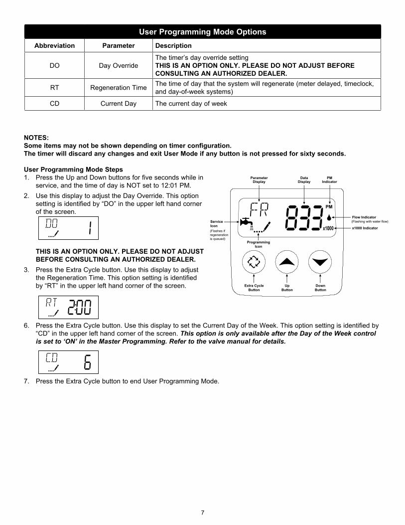
User Programming Mode OptionsAbbreviation Parameter Description
DO Day OverrideThe timer’s day override setting THIS IS AN OPTION ONLY. PLEASE DO NOT ADjUST BEFORE CONSULTING AN AUTHORIzED DEALER.
RT Regeneration Time The time of day that the system will regenerate (meter delayed, timeclock, and day-of-week systems)
CD Current Day The current day of week
NOTES:Some items may not be shown depending on timer configuration.The timer will discard any changes and exit User Mode if any button is not pressed for sixty seconds.
User Programming Mode Steps1. Press the Up and Down buttons for five seconds while in
service, and the time of day is NOT set to 12:01 PM.2. Use this display to adjust the Day Override. This option
setting is identified by “DO” in the upper left hand corner of the screen.
THIS IS AN OPTION ONLY. PLEASE DO NOT ADjUST BEFORE CONSULTING AN AUTHORIzED DEALER.
3. Press the Extra Cycle button. Use this display to adjust the Regeneration Time. This option setting is identified by “RT” in the upper left hand corner of the screen.
6. Press the Extra Cycle button. Use this display to set the Current Day of the Week. This option setting is identified by “CD” in the upper left hand corner of the screen. This option is only available after the Day of the Week control is set to ‘ON’ in the Master Programming. Refer to the valve manual for details.
7. Press the Extra Cycle button to end User Programming Mode.
8
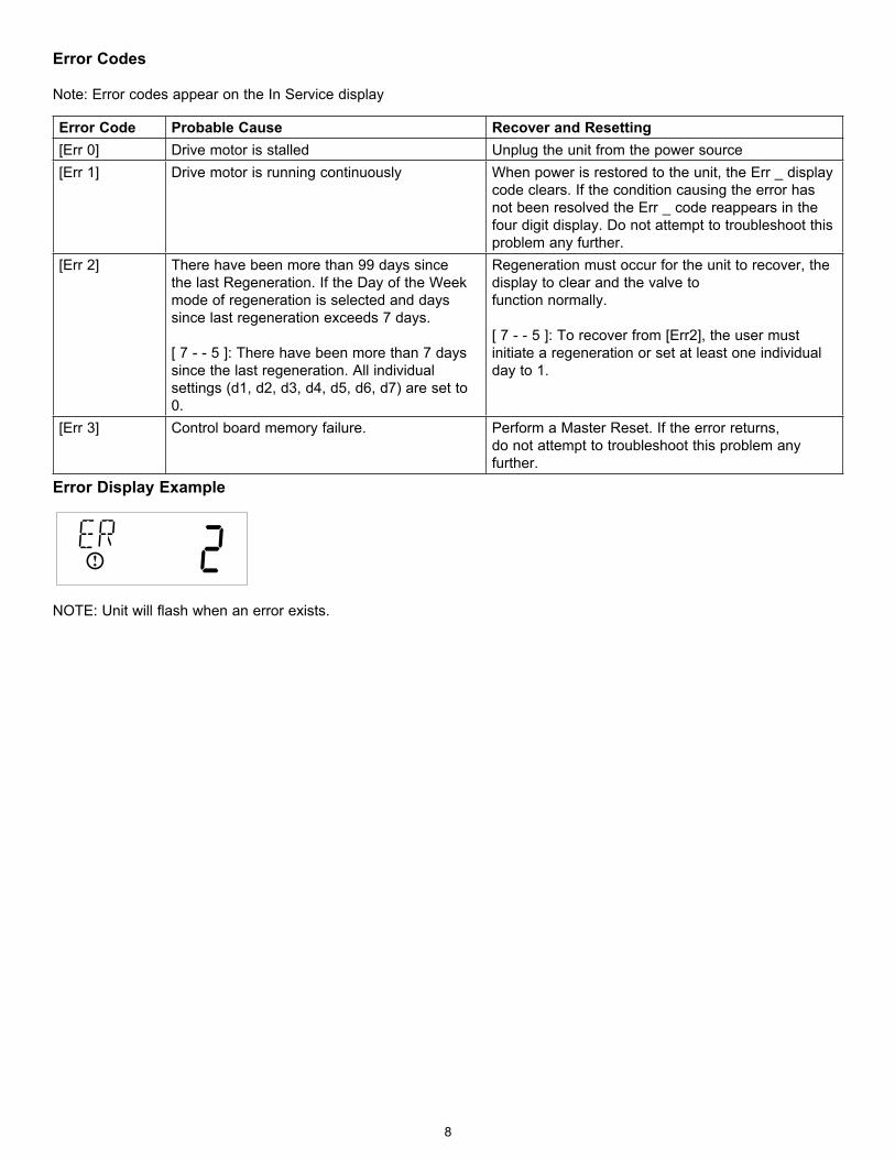
Error Codes
Note: Error codes appear on the In Service display
Error Display Example
NOTE: Unit will flash when an error exists.
Error Code Probable Cause Recover and Resetting[Err 0] Drive motor is stalled Unplug the unit from the power source[Err 1] Drive motor is running continuously When power is restored to the unit, the Err _ display
code clears. If the condition causing the error has not been resolved the Err _ code reappears in the four digit display. Do not attempt to troubleshoot this problem any further.
[Err 2] There have been more than 99 days since the last Regeneration. If the Day of the Week mode of regeneration is selected and days since last regeneration exceeds 7 days.
[ 7 - - 5 ]: There have been more than 7 days since the last regeneration. All individual settings (d1, d2, d3, d4, d5, d6, d7) are set to 0.
Regeneration must occur for the unit to recover, the display to clear and the valve tofunction normally.
[ 7 - - 5 ]: To recover from [Err2], the user must initiate a regeneration or set at least one individual day to 1.
[Err 3] Control board memory failure. Perform a Master Reset. If the error returns,do not attempt to troubleshoot this problem any further.

9
Manual Backwash CycleIf you run out of treated water because of inadequate regeneration frequency, inadequate reserve capacity, power failure or unusually high water usage, you can initiate a manual regeneration simply by pressing the extra cycle button. The filter will now automatically complete a regeneration cycle and return to service. If possible, avoid water use during the regeneration cycle.
Once you have set your filter and you experience frequent loss of water pressure, you may have to increase the frequency of regeneration by resetting the gallons between regeneration.
Water PressureYour filter is designed to operated under normal water pressures from 20 psi (1.4 atm) to 125 psi (8.5 atm).
New SoundsYou may notice new sounds as your water filter operates. The regeneration cycle lasts approximately 20 minutes. During this time, you may hear water running intermittently to the drain.
Manual Bypass (Figure 5A)In case of an emergency, you can isolate your water filter from the water supply using the bypass valve located at the back of the control.
In normal operation the bypass is open with the ON/OFF knobs in line with the INLET and OUTLET pipes. To isolate the filter, simply rotate the knobs clockwise (as indicated by the word BYPASS and arrow) until they lock.
You can use your water related fixtures and appliances as the water supply is bypassing the filter. However, the water you use will be untreated.
To resume treated water service, open the bypass valve by rotating the knobs counter-clockwise.
Stainless Steel Bypass (Figure 5B)In normal operation the bypass lever is aligned with the inlet/outlet with the pointer on SERVICE. To isolate the filter, rotate lever counter clockwise until it stops and pointer indicates unit is in bypass.You can use your water related fixtures and appliances as the water supply is bypassing the filter. However, the water you use will be unfiltered.To resume filtered water service, open the bypass valve by reversing the rotation of the lever.
OUTLET
INLET
Figure 5A
OUTLET
INLET
Figure 5B
10
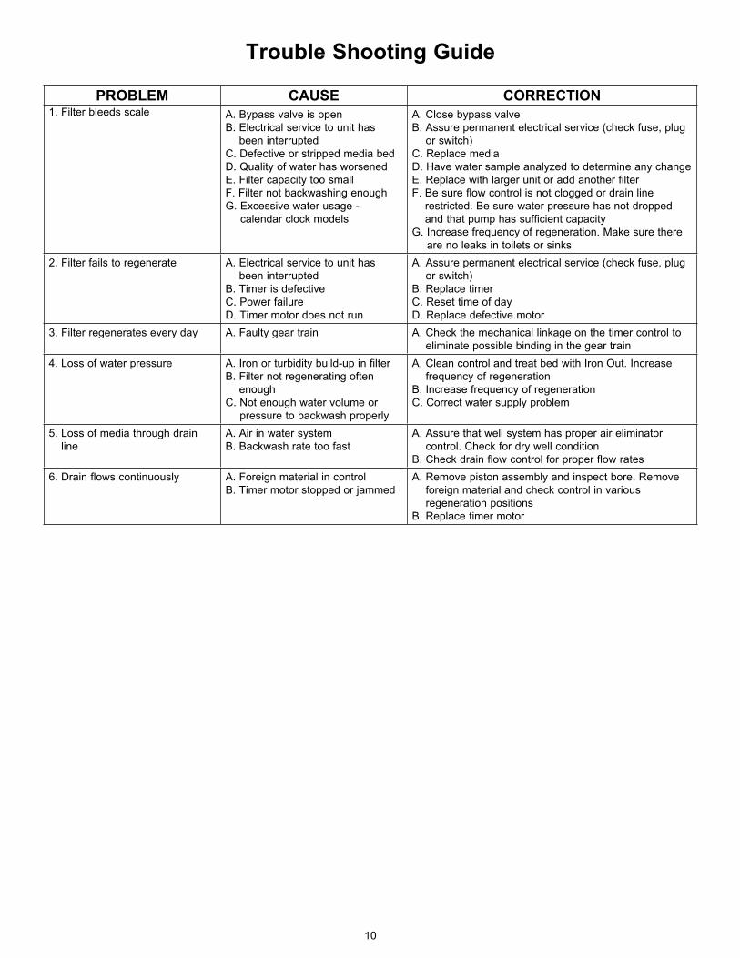
Trouble Shooting Guide
PROBLEM CAUSE CORRECTION1. Filter bleeds scale A. Bypass valve is open
B. Electrical service to unit has been interrupted
C. Defective or stripped media bedD. Quality of water has worsenedE. Filter capacity too smallF. Filter not backwashing enoughG. Excessive water usage -
calendar clock models
A. Close bypass valveB. Assure permanent electrical service (check fuse, plug
or switch)C. Replace mediaD. Have water sample analyzed to determine any changeE. Replace with larger unit or add another filterF. Be sure flow control is not clogged or drain line
restricted. Be sure water pressure has not dropped and that pump has sufficient capacity
G. Increase frequency of regeneration. Make sure there are no leaks in toilets or sinks
2. Filter fails to regenerate A. Electrical service to unit has been interrupted
B. Timer is defectiveC. Power failureD. Timer motor does not run
A. Assure permanent electrical service (check fuse, plug or switch)
B. Replace timerC. Reset time of dayD. Replace defective motor
3. Filter regenerates every day A. Faulty gear train A. Check the mechanical linkage on the timer control to eliminate possible binding in the gear train
4. Loss of water pressure A. Iron or turbidity build-up in filterB. Filter not regenerating often
enoughC. Not enough water volume or
pressure to backwash properly
A. Clean control and treat bed with Iron Out. Increase frequency of regeneration
B. Increase frequency of regenerationC. Correct water supply problem
5. Loss of media through drain line
A. Air in water systemB. Backwash rate too fast
A. Assure that well system has proper air eliminator control. Check for dry well condition
B. Check drain flow control for proper flow rates6. Drain flows continuously A. Foreign material in control
B. Timer motor stopped or jammedA. Remove piston assembly and inspect bore. Remove
foreign material and check control in various regeneration positions
B. Replace timer motor

WaterGroup GuaranteeWaterGroup Inc. guarantees that your new water conditioner is built of quality material and workmanship. When properly installed and maintained, it will give years of trouble free service.
Five Year Complete Parts Guarantee:WaterGroup Inc. will replace any part which fails within 60 months from date of manufacture, as indicated by the serial number provided the failure is due to a defect in material or workmanship. The only exception shall be when proof of purchase or installation is provided and then the warranty period shall be from the date thereof.
Ten Year Guarantee on Mineral Tanks and Brine Tanks:WaterGroup Inc. will provide a replacement mineral tank or brine tank to any original equipment purchaser in possession of a tank that fails within 120 months, provided that the water conditioner is at all times operated in accordance with specifications and not subject to freezing.
General Provisions:WaterGroup Inc. assumes no responsibility for consequential damage, labor or expense incurred as a result of a defect or for failure to meet the terms of these guarantees because of circumstances beyond its control.
Contact your local Distributor:
U.S. HeadquartersWaterGroup Companies, Inc.193 Osborne RoadFridley, MN 55432, USATOll FRee PhONe: 1-877-581-1833
Canada HeadquartersWaterGroup Companies, Inc.490 Pinebush Road, Unit 1Cambridge, ON N1T 0A5, CanadaTOll FRee PhONe: 1-877-288-9888
www.watergroup.com
Distribution LocationsDurham, NClibertyville, IlPottstown, PARancho Cucamonga, CACambridge, ONCalgary, ABRegina, SK
54993.0212