Embed Size (px)
Citation preview
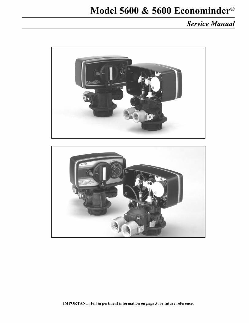
Model 5600 & 5600 Econominder®
Service Manual
IMPORTANT: Fill in pertinent information on page 3 for future reference.
2
Model 5600 & 5600 Econominder®
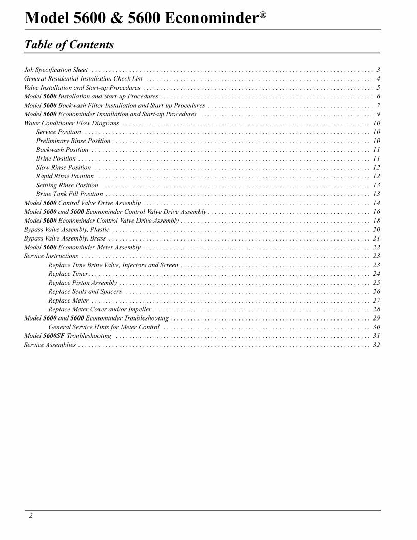
Table of Contents
Job Specification Sheet . . . . . . . . . . . . . . . . . . . . . . . . . . . . . . . . . . . . . . . . . . . . . . . . . . . . . . . . . . . . . . . . . . . . . . . . . . . . . . . . . . . 3General Residential Installation Check List . . . . . . . . . . . . . . . . . . . . . . . . . . . . . . . . . . . . . . . . . . . . . . . . . . . . . . . . . . . . . . . . . . . 4Valve Installation and Start-up Procedures . . . . . . . . . . . . . . . . . . . . . . . . . . . . . . . . . . . . . . . . . . . . . . . . . . . . . . . . . . . . . . . . . . . . 5Model 5600 Installation and Start-up Procedures . . . . . . . . . . . . . . . . . . . . . . . . . . . . . . . . . . . . . . . . . . . . . . . . . . . . . . . . . . . . . . . 6Model 5600 Backwash Filter Installation and Start-up Procedures . . . . . . . . . . . . . . . . . . . . . . . . . . . . . . . . . . . . . . . . . . . . . . . . . 7Model 5600 Econominder Installation and Start-up Procedures . . . . . . . . . . . . . . . . . . . . . . . . . . . . . . . . . . . . . . . . . . . . . . . . . . . 9Water Conditioner Flow Diagrams . . . . . . . . . . . . . . . . . . . . . . . . . . . . . . . . . . . . . . . . . . . . . . . . . . . . . . . . . . . . . . . . . . . . . . . . . 10
Service Position . . . . . . . . . . . . . . . . . . . . . . . . . . . . . . . . . . . . . . . . . . . . . . . . . . . . . . . . . . . . . . . . . . . . . . . . . . . . . . . . . . . . 10Preliminary Rinse Position . . . . . . . . . . . . . . . . . . . . . . . . . . . . . . . . . . . . . . . . . . . . . . . . . . . . . . . . . . . . . . . . . . . . . . . . . . . . 10Backwash Position . . . . . . . . . . . . . . . . . . . . . . . . . . . . . . . . . . . . . . . . . . . . . . . . . . . . . . . . . . . . . . . . . . . . . . . . . . . . . . . . . . 11Brine Position . . . . . . . . . . . . . . . . . . . . . . . . . . . . . . . . . . . . . . . . . . . . . . . . . . . . . . . . . . . . . . . . . . . . . . . . . . . . . . . . . . . . . . 11Slow Rinse Position . . . . . . . . . . . . . . . . . . . . . . . . . . . . . . . . . . . . . . . . . . . . . . . . . . . . . . . . . . . . . . . . . . . . . . . . . . . . . . . . . 12Rapid Rinse Position . . . . . . . . . . . . . . . . . . . . . . . . . . . . . . . . . . . . . . . . . . . . . . . . . . . . . . . . . . . . . . . . . . . . . . . . . . . . . . . . . 12Settling Rinse Position . . . . . . . . . . . . . . . . . . . . . . . . . . . . . . . . . . . . . . . . . . . . . . . . . . . . . . . . . . . . . . . . . . . . . . . . . . . . . . . 13Brine Tank Fill Position . . . . . . . . . . . . . . . . . . . . . . . . . . . . . . . . . . . . . . . . . . . . . . . . . . . . . . . . . . . . . . . . . . . . . . . . . . . . . . 13
Model 5600 Control Valve Drive Assembly . . . . . . . . . . . . . . . . . . . . . . . . . . . . . . . . . . . . . . . . . . . . . . . . . . . . . . . . . . . . . . . . . . . 14Model 5600 and 5600 Econominder Control Valve Drive Assembly . . . . . . . . . . . . . . . . . . . . . . . . . . . . . . . . . . . . . . . . . . . . . . . . 16Model 5600 Econominder Control Valve Drive Assembly . . . . . . . . . . . . . . . . . . . . . . . . . . . . . . . . . . . . . . . . . . . . . . . . . . . . . . . . 18Bypass Valve Assembly, Plastic . . . . . . . . . . . . . . . . . . . . . . . . . . . . . . . . . . . . . . . . . . . . . . . . . . . . . . . . . . . . . . . . . . . . . . . . . . . . 20Bypass Valve Assembly, Brass . . . . . . . . . . . . . . . . . . . . . . . . . . . . . . . . . . . . . . . . . . . . . . . . . . . . . . . . . . . . . . . . . . . . . . . . . . . . . 21Model 5600 Econominder Meter Assembly . . . . . . . . . . . . . . . . . . . . . . . . . . . . . . . . . . . . . . . . . . . . . . . . . . . . . . . . . . . . . . . . . . . 22Service Instructions . . . . . . . . . . . . . . . . . . . . . . . . . . . . . . . . . . . . . . . . . . . . . . . . . . . . . . . . . . . . . . . . . . . . . . . . . . . . . . . . . . . . . 23
Replace Time Brine Valve, Injectors and Screen . . . . . . . . . . . . . . . . . . . . . . . . . . . . . . . . . . . . . . . . . . . . . . . . . . . . . . . . 23Replace Timer. . . . . . . . . . . . . . . . . . . . . . . . . . . . . . . . . . . . . . . . . . . . . . . . . . . . . . . . . . . . . . . . . . . . . . . . . . . . . . . . . . . 24Replace Piston Assembly . . . . . . . . . . . . . . . . . . . . . . . . . . . . . . . . . . . . . . . . . . . . . . . . . . . . . . . . . . . . . . . . . . . . . . . . . . 25Replace Seals and Spacers . . . . . . . . . . . . . . . . . . . . . . . . . . . . . . . . . . . . . . . . . . . . . . . . . . . . . . . . . . . . . . . . . . . . . . . . 26Replace Meter . . . . . . . . . . . . . . . . . . . . . . . . . . . . . . . . . . . . . . . . . . . . . . . . . . . . . . . . . . . . . . . . . . . . . . . . . . . . . . . . . . 27Replace Meter Cover and/or Impeller . . . . . . . . . . . . . . . . . . . . . . . . . . . . . . . . . . . . . . . . . . . . . . . . . . . . . . . . . . . . . . . . 28
Model 5600 and 5600 Econominder Troubleshooting . . . . . . . . . . . . . . . . . . . . . . . . . . . . . . . . . . . . . . . . . . . . . . . . . . . . . . . . . . . 29General Service Hints for Meter Control . . . . . . . . . . . . . . . . . . . . . . . . . . . . . . . . . . . . . . . . . . . . . . . . . . . . . . . . . . . . . 30
Model 5600SF Troubleshooting . . . . . . . . . . . . . . . . . . . . . . . . . . . . . . . . . . . . . . . . . . . . . . . . . . . . . . . . . . . . . . . . . . . . . . . . . . . 31Service Assemblies . . . . . . . . . . . . . . . . . . . . . . . . . . . . . . . . . . . . . . . . . . . . . . . . . . . . . . . . . . . . . . . . . . . . . . . . . . . . . . . . . . . . . . 32
Model 5600 & 5600 Econominder®
3
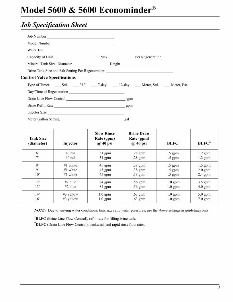
Job Specification SheetJob Number ___________________________________
Model Number ________________________________
Water Test ____________________________________
Capacity of Unit ________________________ Max. _____________ Per Regeneration
Mineral Tank Size: Diameter ___________________ Height _____________________
Brine Tank Size and Salt Setting Per Regeneration: ___________________________________
Control Valve SpecificationsType of Timer: ___ Std. ___ "L" ___ 7-day ___ 12-day ___ Meter, Std. ___ Meter, Ext.
Day/Time of Regeneration _____________________________
Drain Line Flow Control _______________________________ gpm
Brine Refill Rate _____________________________________ gpm
Injector Size ________________________________________
Meter Gallon Setting _________________________________ gal
NOTE: Due to varying water conditions, tank sizes and water pressures, use the above settings as guidelines only.
1BLFC (Brine Line Flow Control), refill rate for filling brine tank.2DLFC (Drain Line Flow Control), backwash and rapid rinse flow rates.
Tank Size(diameter) Injector
Slow RinseRate (gpm)
@ 40 psi
Brine DrawRate (gpm)
@ 40 psi BLFC1 BLFC2
6"7"
#0 red#0 red
.31 gpm
.31 gpm.28 gpm.28 gpm
.5 gpm
.5 gpm1.2 gpm1.2 gpm
8"9"
10"
#1 white#1 white#1 white
.45 gpm
.45 gpm
.45 gpm
.38 gpm
.38 gpm
.38 gpm
.5 gpm
.5 gpm
.5 gpm
1.5 gpm2.0 gpm2.4 gpm
12"13"
#2 blue#2 blue
.84 gpm
.84 gpm.56 gpm.56 gpm
1.0 gpm1.0 gpm
3.5 gpm4.0 gpm
14"16"
#3 yellow#3 yellow
1.0 gpm1.0 gpm
.63 gpm
.63 gpm1.0 gpm1.0 gpm
5.0 gpm7.0 gpm
4
Model 5600 & 5600 Econominder®
General Residential Installation Check ListWater Pressure
A minimum of 25 lbs of water pressure is required for regeneration valve to operate effectively.
Electrical FacilitiesAn uninterrupted alternating current (A/C) supply is required. Please make sure voltage supply is compatible with unit before installation.
Existing PlumbingCondition of existing plumbing should be free from lime and iron buildup. Replace piping that has heavy lime and/or iron build-up. If piping is clogged with iron, install a separate iron filter unit ahead of the water softener.
Location of Softener and DrainLocate the softener close to a clean working drain and connect according to local plumbing codes.
Bypass ValvesAlways provide for the installation of a bypass valve if unit is not equipped with one.
CAUTION• Do not exceed 120 psi water pressure.• Do not exceed 110°F water temperature.• Do not subject unit to freezing conditions.
Model 5600 & 5600 Econominder®
5
Valve Installation and Start-up Procedures1. Place the softener tank where you want to install the unit.
NOTE: Be sure the tank is level and on a firm base.
2. During cold weather it is recommended that the installer warm the valve to room temperature before operating.
3. Perform all plumbing according to local plumbing codes.
— Use a 1/2" minimum pipe size for the drain.
— Use a 3/4" drain line for backwash flow rates that exceed 7 gpm or length that exceeds 20′ (6 m).
4. Cut the 1" distributor tube (1.050 O.D.) flush with top of each tank.
NOTE: Only use silicone lubricant.
5. Lubricate the distributor o-ring seal and tank o-ring seal. Place the main control valve on tank.
6. Solder joints near the drain must be done before connecting the Drain Line Flow Control fitting (DLFC). Leave at least 6" (152 mm) between the DLFC and solder joints when soldering pipes that are connected on the DLFC. Failure to do this could cause interior damage to DLFC.
7. Use only Teflon tape on the drain fitting.
8. Be sure the floor under the salt storage tank is clean and level.
9. Place approximately 1" (25 mm) of water above the grid plate. If a grid is not utilized, fill to the top of the air check in the salt tank. Do not add salt to the brine tank at this time.
10. On units with a bypass, place in Bypass position.
— Turn on the main water supply.
— Open a cold soft water tap nearby and let water run a few minutes or until the system is free of foreign material (usually solder) resulting from the installation. Close the water tap when water runs clean.
11. Place the bypass in the In Service position and let water flow into the mineral tank. When water flow stops, slowly open a cold water tap nearby and let water run until air is purged from the unit. Then close tap.
12. Plug the valve into an approved power source. When the valve has power it drives to the In Service position.
6
Model 5600 & 5600 Econominder®
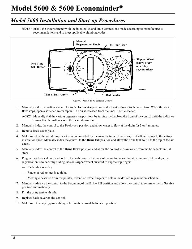
Model 5600 Installation and Start-up ProceduresNOTE: Install the water softener with the inlet, outlet and drain connections made according to manufacturer’s
recommendations and to meet applicable plumbing codes.
1. Manually index the softener control into the In Service position and let water flow into the resin tank. When the water flow stops, open a softened water tap until all air is released from the lines. Then close tap.
NOTE: Manually dial the various regeneration positions by turning the knob on the front of the control until the indicator shows that the softener is in the desired position.
2. Manually index the control to the Backwash position and allow water to flow at the drain for 3 or 4 minutes.
3. Remove back cover plate.
4. Make sure that the salt dosage is set as recommended by the manufacturer. If necessary, set salt according to the setting instruction sheet. Manually index the control to the Brine Fill position and allow the brine tank to fill to the top of the air check.
5. Manually index the control to the Brine Draw position and allow the control to draw water from the brine tank until it stops.
6. Plug in the electrical cord and look in the sight hole in the back of the motor to see that it is running. Set the days that regeneration is to occur by sliding tabs on skipper wheel outward to expose trip fingers.
— Each tab is one day.
— Finger at red pointer is tonight.
— Moving clockwise from red pointer, extend or retract fingers to obtain the desired regeneration schedule.
7. Manually advance the control to the beginning of the Brine Fill position and allow the control to return to the In Service position automatically.
8. Fill the brine tank with salt.
9. Replace back cover on the control.
10. Make sure that any bypass valving is left in the normal In Service position.
Figure 1: Model 5600 Softener Control
Manual24-Hour Gear
Skipper Wheel
Red PointerTime of Day Arrow
Red Time
Regeneration Knob
(shows everyother dayregeneration)
Set Button
Model 5600 & 5600 Econominder®
7
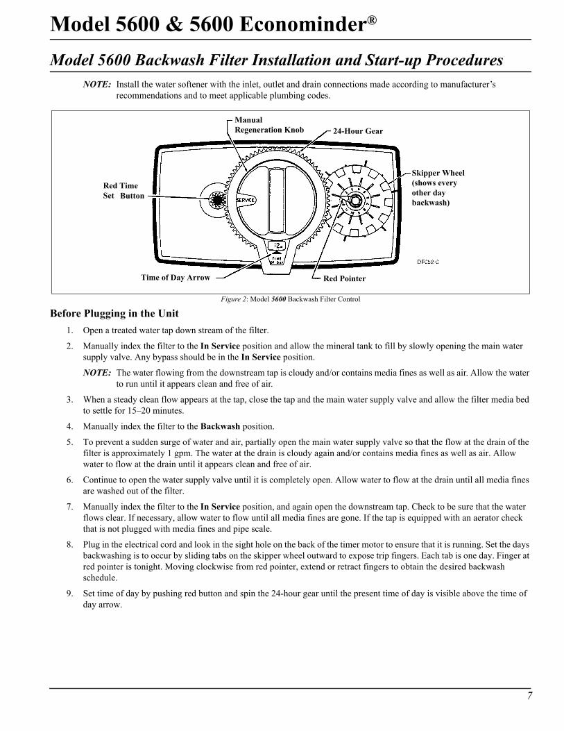
Model 5600 Backwash Filter Installation and Start-up ProceduresNOTE: Install the water softener with the inlet, outlet and drain connections made according to manufacturer’s
recommendations and to meet applicable plumbing codes.
Before Plugging in the Unit1. Open a treated water tap down stream of the filter.
2. Manually index the filter to the In Service position and allow the mineral tank to fill by slowly opening the main water supply valve. Any bypass should be in the In Service position.
NOTE: The water flowing from the downstream tap is cloudy and/or contains media fines as well as air. Allow the water to run until it appears clean and free of air.
3. When a steady clean flow appears at the tap, close the tap and the main water supply valve and allow the filter media bed to settle for 15–20 minutes.
4. Manually index the filter to the Backwash position.
5. To prevent a sudden surge of water and air, partially open the main water supply valve so that the flow at the drain of the filter is approximately 1 gpm. The water at the drain is cloudy again and/or contains media fines as well as air. Allow water to flow at the drain until it appears clean and free of air.
6. Continue to open the water supply valve until it is completely open. Allow water to flow at the drain until all media fines are washed out of the filter.
7. Manually index the filter to the In Service position, and again open the downstream tap. Check to be sure that the water flows clear. If necessary, allow water to flow until all media fines are gone. If the tap is equipped with an aerator check that is not plugged with media fines and pipe scale.
8. Plug in the electrical cord and look in the sight hole on the back of the timer motor to ensure that it is running. Set the days backwashing is to occur by sliding tabs on the skipper wheel outward to expose trip fingers. Each tab is one day. Finger at red pointer is tonight. Moving clockwise from red pointer, extend or retract fingers to obtain the desired backwash schedule.
9. Set time of day by pushing red button and spin the 24-hour gear until the present time of day is visible above the time of day arrow.
Figure 2: Model 5600 Backwash Filter Control
Manual24-Hour Gear
Skipper Wheel
Red PointerTime of Day Arrow
Red Time
Regeneration Knob
(shows everyother daybackwash)
Set Button
8
Model 5600 & 5600 Econominder®
Model 5600 Backwash Filter Installation and Start-up Procedures (Cont’d.)Cycle Times and Flow Diagrams
1. In Service position. See Figure 4, page 10.
2. Preliminary Rinse position.
— Same as Figure 4, page 10 with standard piston (white end plug) or filter piston (black end plug).
— Eliminated with low water piston (gray end plug).
3. Backwash position.
— Same as Figure 6, page 11 with standard piston.
— 15 minutes with filter piston.
— 7 minutes with low water piston.
4. Brine Rinse position.
— Eliminated, resulting in a 50 minute pause, no water flows during this time.
5. Slow Rinse position.
— Eliminated, resulting in a 50 minute pause, no water flows during this time.
6. Second Backwash position.
— Same as Figure 9, page 12 with standard piston.
— 15 minutes with filter piston.
— 7 minutes with low water piston.
7. Settling Rinse position.
— Same as Figure 10, page 13 with standard or filter piston.
— Eliminate with low water piston.
8. Brine Tank Refill position.
— Eliminated, filter is back in service at this time.
Model 5600 & 5600 Econominder®
9
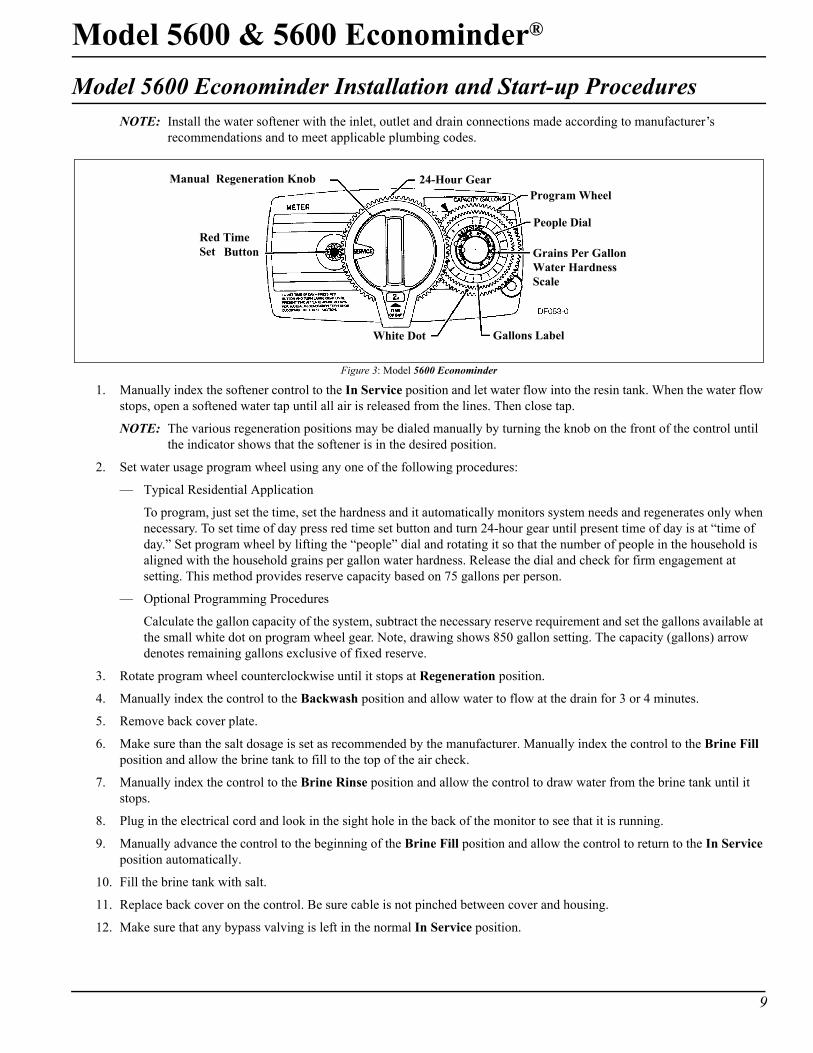
Model 5600 Econominder Installation and Start-up ProceduresNOTE: Install the water softener with the inlet, outlet and drain connections made according to manufacturer’s
recommendations and to meet applicable plumbing codes.
1. Manually index the softener control to the In Service position and let water flow into the resin tank. When the water flow stops, open a softened water tap until all air is released from the lines. Then close tap.
NOTE: The various regeneration positions may be dialed manually by turning the knob on the front of the control until the indicator shows that the softener is in the desired position.
2. Set water usage program wheel using any one of the following procedures:
— Typical Residential Application
To program, just set the time, set the hardness and it automatically monitors system needs and regenerates only when necessary. To set time of day press red time set button and turn 24-hour gear until present time of day is at “time of day.” Set program wheel by lifting the “people” dial and rotating it so that the number of people in the household is aligned with the household grains per gallon water hardness. Release the dial and check for firm engagement at setting. This method provides reserve capacity based on 75 gallons per person.
— Optional Programming Procedures
Calculate the gallon capacity of the system, subtract the necessary reserve requirement and set the gallons available at the small white dot on program wheel gear. Note, drawing shows 850 gallon setting. The capacity (gallons) arrow denotes remaining gallons exclusive of fixed reserve.
3. Rotate program wheel counterclockwise until it stops at Regeneration position.
4. Manually index the control to the Backwash position and allow water to flow at the drain for 3 or 4 minutes.
5. Remove back cover plate.
6. Make sure than the salt dosage is set as recommended by the manufacturer. Manually index the control to the Brine Fill position and allow the brine tank to fill to the top of the air check.
7. Manually index the control to the Brine Rinse position and allow the control to draw water from the brine tank until it stops.
8. Plug in the electrical cord and look in the sight hole in the back of the monitor to see that it is running.
9. Manually advance the control to the beginning of the Brine Fill position and allow the control to return to the In Service position automatically.
10. Fill the brine tank with salt.
11. Replace back cover on the control. Be sure cable is not pinched between cover and housing.
12. Make sure that any bypass valving is left in the normal In Service position.
Figure 3: Model 5600 Econominder
Manual 24-Hour Gear
White Dot
Red Time
Regeneration Knob
Set Button
Gallons Label
Program Wheel
People Dial
Grains Per GallonWater HardnessScale
10
Model 5600 & 5600 Econominder®
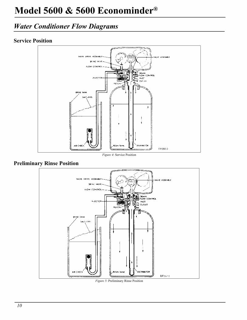
Water Conditioner Flow Diagrams
Service Position
Preliminary Rinse Position
Figure 4: Service Position
Figure 5: Preliminary Rinse Position
Model 5600 & 5600 Econominder®
11
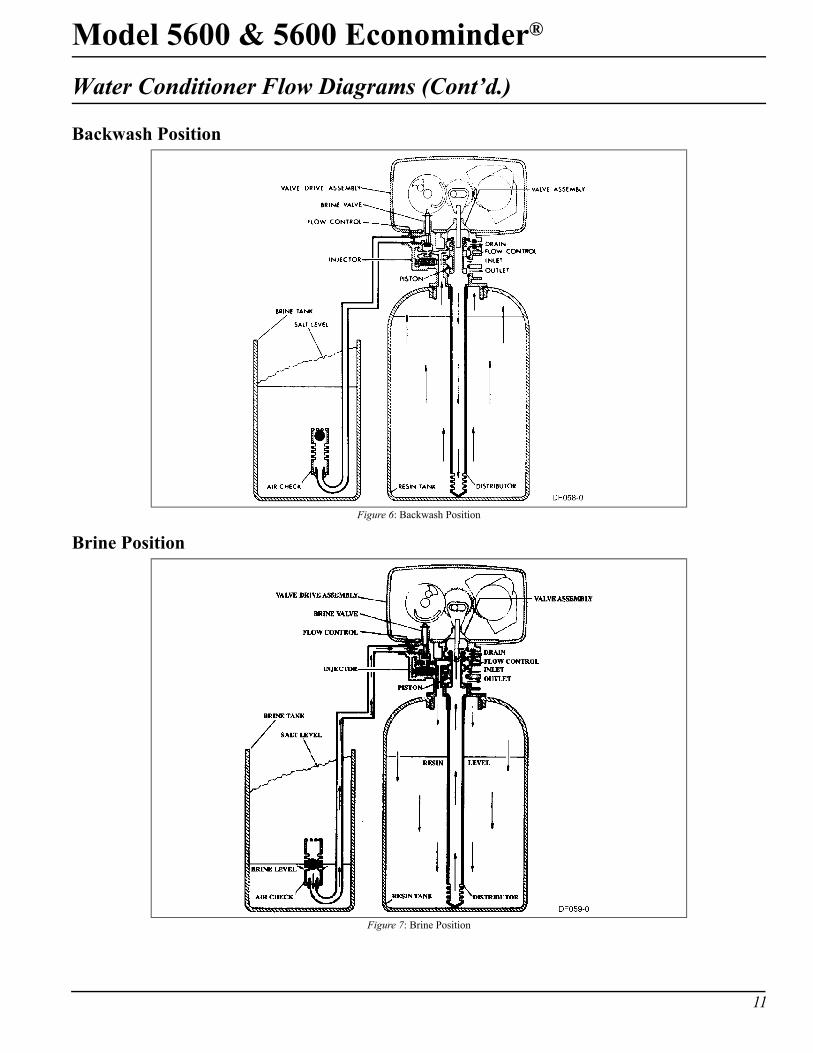
Water Conditioner Flow Diagrams (Cont’d.)
Backwash Position
Brine Position
Figure 6: Backwash Position
Figure 7: Brine Position
12
Model 5600 & 5600 Econominder®
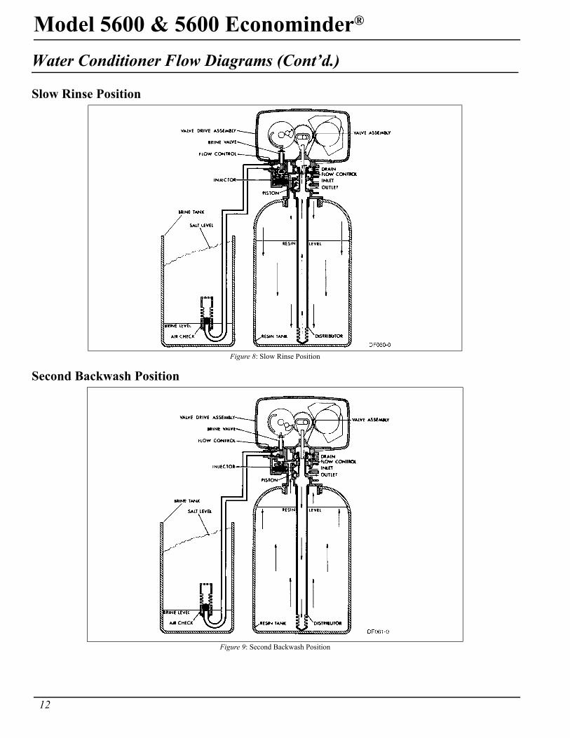
Water Conditioner Flow Diagrams (Cont’d.)
Slow Rinse Position
Second Backwash Position
Figure 8: Slow Rinse Position
Figure 9: Second Backwash Position
Model 5600 & 5600 Econominder®
13
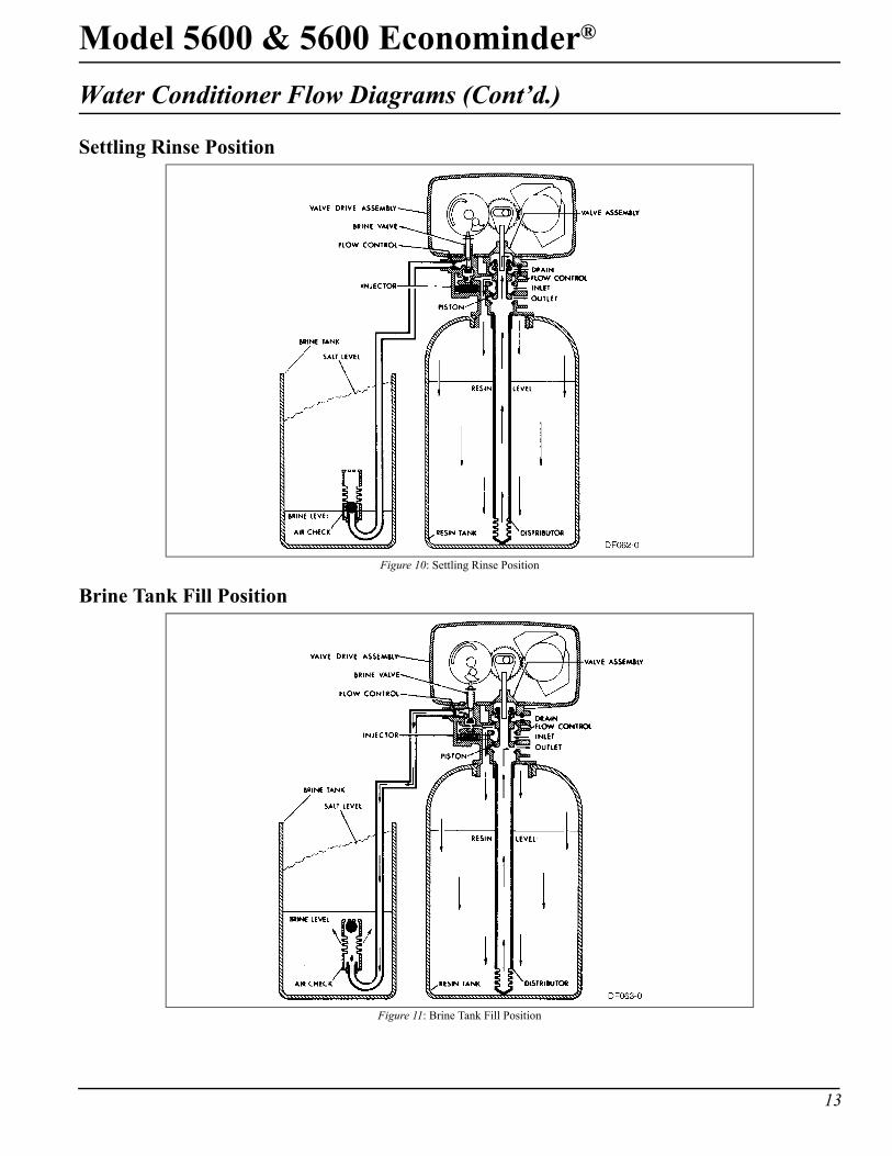
Water Conditioner Flow Diagrams (Cont’d.)
Settling Rinse Position
Brine Tank Fill Position
Figure 10: Settling Rinse Position
Figure 11: Brine Tank Fill Position
14
Model 5600 & 5600 Econominder®
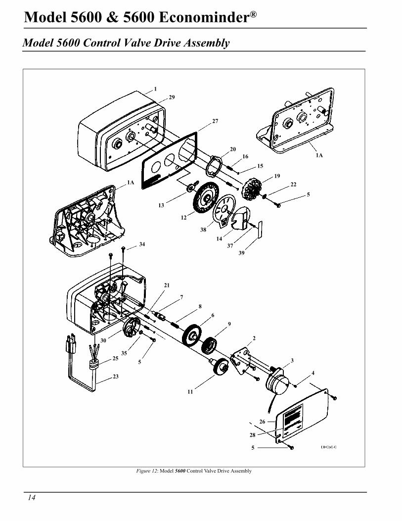
Model 5600 Control Valve Drive Assembly
Figure 12: Model 5600 Control Valve Drive Assembly
129
27
2016
15
1922
5
1A
1A
13
1437
39
12
38
34
21
78
69
2
3
4
11
26
28
5
30
35
23
525
Model 5600 & 5600 Econominder®
15
Model 5600 Control Valve Drive Assembly
▲ Not used when a filter valve
Item Number No. Req’d Part Number Description
1 1 14448-010 housing, with pin1 14448-011 housing, with pin drilled for screw1 14448-012 housing, with pin drilled for thumb screw
1A 1 15494-01 “L” housing, with pin1 15494-03 “L” housing, with pin drilled for designer
2 1 13175 motor mounting plate3 1 18743 motor, 120V, 60 Hz
1 19659 motor, 24V, 60 Hz4 (2-3) 11384 screw, motor mtg. and ground wire5 (3-5) 13296 screw, component mounting6 1 13017 idler gear7 1 13018 idler pinion8 1 13312 spring, idler9 1 13164 drive gear
11 1 13170 main gear and shaft12 1 19205 24-hour gear assembly, silver
1 19205-01 24-hour gear assembly, tan13 1 13011 cycle actuator gear14 1 14177 knob, manual regeneration15 4 13300 ball, 1/4″ dia.16 2 13311 spring, detent, skipper wheel19 1 14381 skipper wheel assembly, 12-day
1 14860 skipper wheel assembly, 7-day20 1 13864 skipper wheel ring21 2 14457 spring, detent, main gear22 1 13014 regeneration pointer23 1 11842 electrical cord, standard24 2 12681 wire connector (not shown)25 1 13547 strain relief26 1 13229 back cover27 1 13309 front label, brown on beige
1 13437 front label, blue/silver on black28 1 13310 rear label, softener
1 18520 rear label, filter29 1 13348 tape stripe, brown on beige
1 13436 tape stripe, blue on silver30▲ 1 60514 brine cam assembly, 3-18
1 60514-01 brine cam assembly, 6-361 60514-02 brine cam assembly, minutes
34 2 12473 screw-drive mounting35▲ 1 12037 washer
37 1 15151 screw, knob38 1 14176 valve position dial, standard
1 14278 valve position dial, low water1 15478 valve position dial, chemical filter1 16715 valve position dial, filter
39 1 14175 knob label, beige1 14207 knob label, silver
40▲ 1 40214 screw, brine cam
16
Model 5600 & 5600 Econominder®
Model 5600 and 5600 Econominder Control Valve Drive Assembly
Figure 13: Model 5600 and 5600 Econominder Control Valve Drive Assembly
48
47
1049
50
12
11
9
8
2
7
2
316 15
1 17
55
2022
2321
26
1453
39
4243
52
Backwash Filter Injector Option
343332
29
20
30
20
31
2728
46
18
419
42 435
22
3940
38
52
4144
3736
35
2423
2126
1651
45
14
Model 5600 & 5600 Econominder®
17
Model 5600 and 5600 Econominder Control Valve Drive Assembly
* not used with meter controls▲ used in backwash filter
Item Number No. Req’d Part Number Description1 2-4 13255 adapter clip (clock or meter)2 5 13242 seal
5 17772 silicone seal3 1 61400-12 valve body assembly, 1″ dist.
1 61400-11 valve body assembly, 3/4″ dist.4 1 13304 o-ring, distributor tube, 1″
1 10244 o-ring, distributor tube, 13/16″5 1 12281 o-ring, top of tank6 6 not assigned7 4 14241 spacer8 1 13247 piston, standard
1 13781 piston, low water1 13852 piston, filter
9 1 10696 piston pin10 1 13001 piston rod assembly11 1 12953 piston retainer12 1 13446 end plug assembly standard, white
1 13446-10 end plug assembly filter, black13 1 13446-20 end plug assembly low water, gray14 2 13315 screw, injector mounting15 2 19228 adapter coupling
16* 4 13305 o-ring, adapter coupling17* 2-4 13314 screw, adapter coupling (clock or meter)18 1 12638 o-ring, drain19 2 13301 o-ring, injector
20▲ 2 13302 o-ring, brine spacer21 1 13303 o-ring, injector cover22 1 13163 injector body
23▲ 1 10913U injector nozzle, undrilled24 1 10914 injector throat, specify size25 1 10227 injector screen26 1 13166 injector cover27 1 13172 brine valve stem28 1 12626 brine valve seat29 1 13165 brine valve cap30 1 13167 brine valve spacer31 1 12550 quad ring32 1 11973 spring, brine valve33 1 16098 washer, brine valve34 1 11981-01 retaining ring35 1 10329 BLFC fitting nut36 1 10330 BLFC ferrule37 1 10332 BLFC tube insert38 1 12094 BLFC button, .25 gpm
1 12095 BLFC button, .50 gpm1 12097 BLFC button, 1.0 gpm
39▲ 1 12977 o-ring, BLFC40 1 13245 BLFC button retainer41 1 13244 BLFC fitting, 3/8″42 1 DLFC button, specify size43 1 13173 DLFC button retainer44 1 12767 screen, brine line45 1 15348 o-ring, DLFC (not shown)46 1 13497 air disperser47 1 13546 end plug retainer48 3 12112 screw49 1 13363 washer50 1 13296 screw
51A 1 13398 yoke, brass, 1″ NPT1 13708 yoke, brass, 3/4″ NPT
51B 1 18706 yoke, plastic, 1″ NPT1 18706-02 yoke, plastic 3/4″ NPT
52 1 13308 drain hose barb53 1 13918 BLFC, plug
54▲ 1 13857 brine valve, plug
18
Model 5600 & 5600 Econominder®
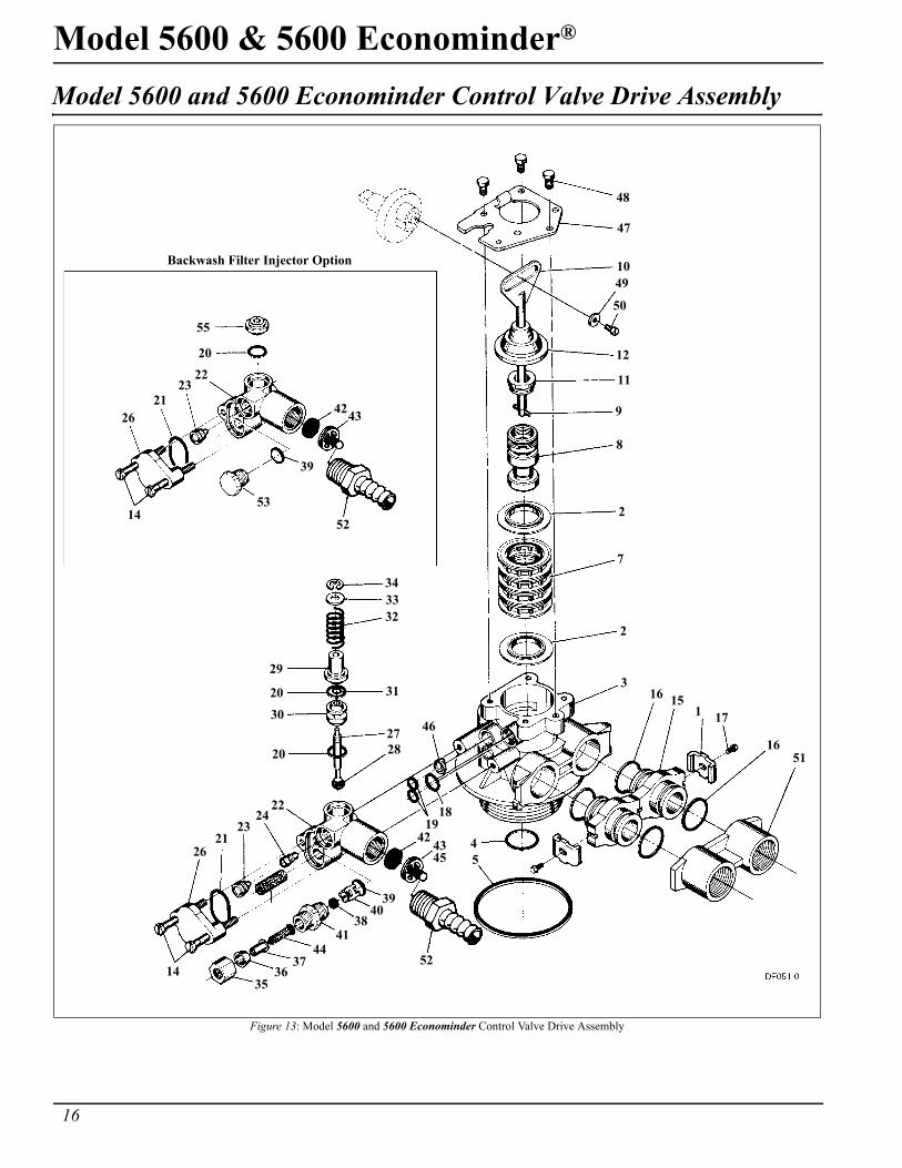
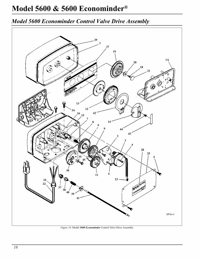
Model 5600 Econominder Control Valve Drive Assembly
Figure 14: Model 5600 Econominder Control Valve Drive Assembly
291
2719
2018
21
1A
13
1242
14
4443
3416
157
86
9
23
4
2825
5
23
511
3545
30
3738
40 3941
2224
Model 5600 & 5600 Econominder®
19
Model 5600 Econominder Control Valve Drive AssemblyItem Number No. Req’d Part Number Description
1 1 14448-000 housing, with roll pin1 14488-001 housing, with pin drilled for screw1 14448-0 housing, with pin drilled for thumb screw
1A 1 15494-01 “L” housing, with pin1 15494-03 “L” housing, with pin drilled for designer
2 1 13175 motor mounting plate3 1 18743 motor, 120V, 60 Hz
1 13494 motor, 24V, 60 Hz4 2-3 11384 screw, motor mtg. and ground wire5 2-4 13296 screw, component mounting6 1 13017 idler gear7 1 13018 idler pinion8 1 13312 spring, idler9 1 13164 drive gear
11 1 13170 main gear and shaft12 1 19205 24-hour gear assembly, silver
1 19205-01 24-hour gear assembly, tan13 1 13802 cycle actuator gear14 1 14177 knob, manual regeneration15 2 13300 ball, 1/4″ dia.16 2 14457 spring, detent18 1 13748 screw, program wheel19 1 60405-15 program skipper wheel assembly, specify hardness capacity20 1 13806 program wheel retainer21 1 13953 cover label, program wheel22 1 11842 electrical cord23 2 12681 wire connector24 1 13547 strain relief25 1 13229 back cover26 not assigned27 1 13955 front label, beige
1 13958 front label, silver28 1 13310 rear label, softener
1 18520 rear label, filter29 1 13957 tape stripe, beige
1 13960 tape stripe, silver30 1 60514 brine cam assembly, 3-18
1 60514-01 brine cam assembly, 6-361 60514-02 brine cam assembly, minutes
34 2 12473 screw-drive mounting35 1 12037 washer37 1 13830 drive pinion, program wheel38 1 13831 clutch, drive pinion39 1 14253 spring retainer40 1 14276 spring41 1 14043 cable assembly, standard
1 14910 cable assembly, extended, right angle42 1 14176 valve position dial, standard
1 14278 valve position dial, low water1 15478 valve position dial, filter
43 1 14175 knob label, beige1 14207 knob label, silver
44 1 15151 screw, knob45 1 40214 screw, brine cam
20
Model 5600 & 5600 Econominder®
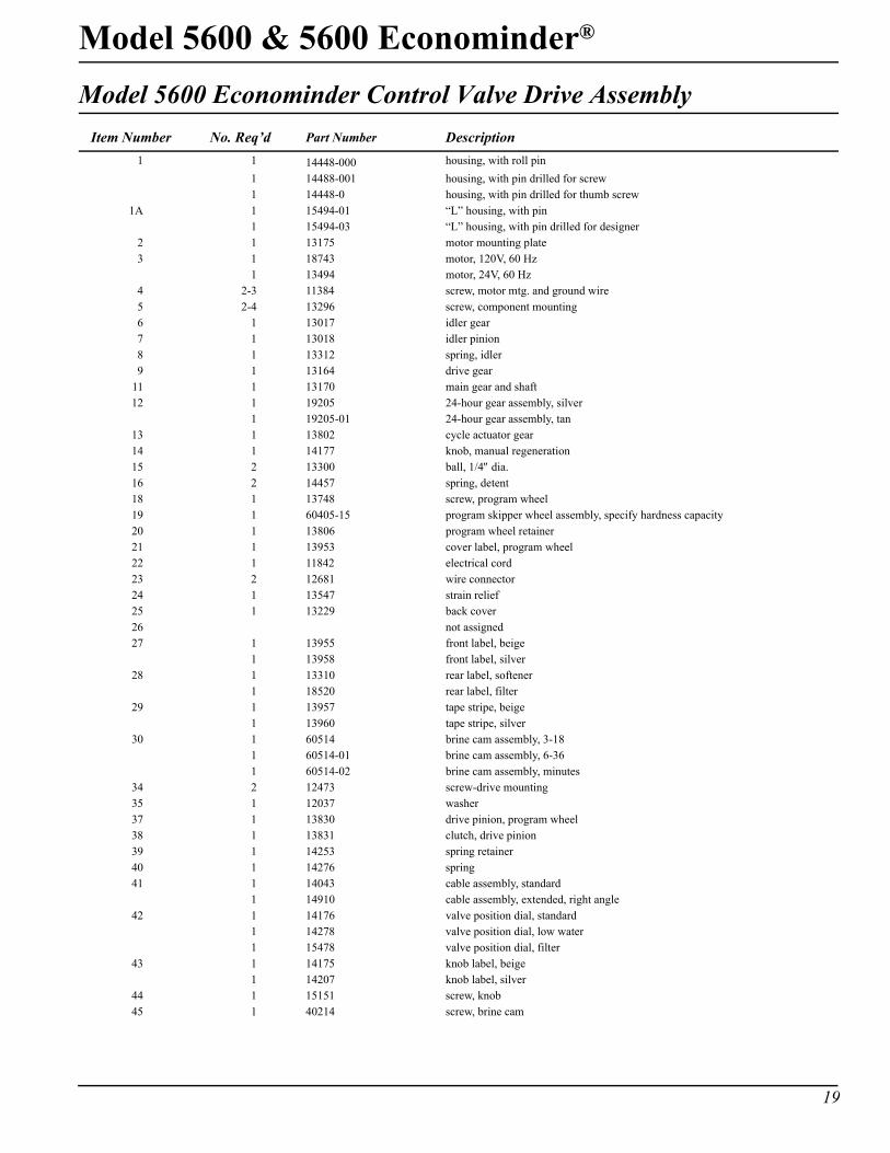
Bypass Valve Assembly, Plastic
Figure 15: Bypass Valve Assembly, Plastic
Item Number No. Req’d Part Number Description9 2 13305 o-ring, 119
10 2 13255 clip, mounting11 2 13314 screw, hex washer head, #8-18 x 5/8"
12A 1 18706 yoke, plastic 1" NPT1 18706-02 yoke, plastic 3/4"
12B 1 13708 yoke, 3/4" 1 13708NP yoke, 3/4" (nickel-plated)1 13398 yoke, 1"1 13398NP yoke, 1" (nickel-plated)
1110
9
12A
12B
Model 5600 & 5600 Econominder®
21
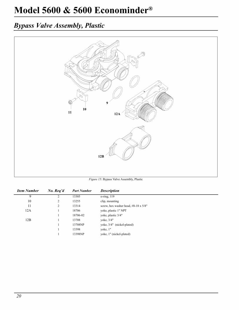
Bypass Valve Assembly, Brass
Figure 16: Bypass Valve Assembly, Brass
Item Number No. Req’d Part Number Description
1 1 17290 bypass valve body, 3/4"1 17290NP bypass valve body, 3/4")1 13399 bypass valve body, 1"1 13399NP bypass valve body, 1" (nickel-plated)
2 1 11726 seal, bypass3 1 11972 plug, bypass4 1 11978 side cover5 1 13604-01 label6 8 15727 screw7 1 11986 side cover8 1 11979 lever, bypass9 1 11989 screw, hex head, 1/4-14
9
8
6
5
4
3
2
1
7
6
22
Model 5600 & 5600 Econominder®
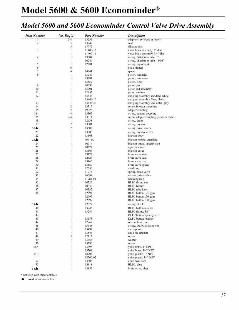
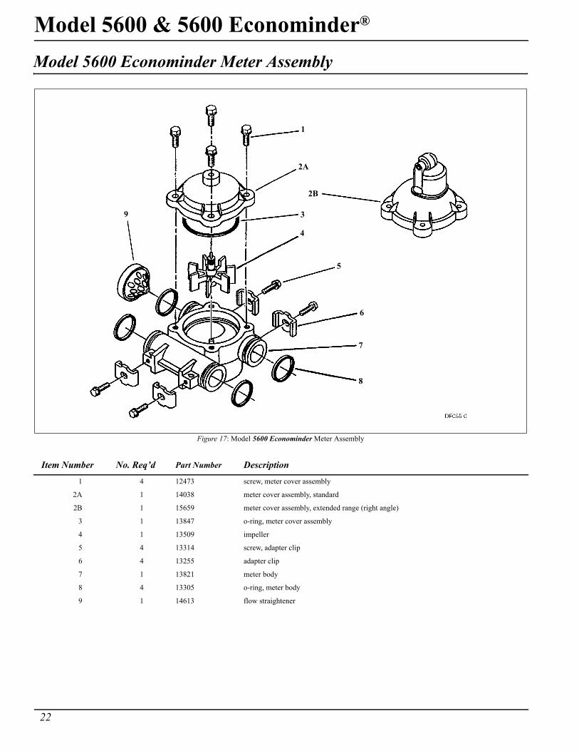
Model 5600 Econominder Meter Assembly
Figure 17: Model 5600 Econominder Meter Assembly
Item Number No. Req’d Part Number Description
1 4 12473 screw, meter cover assembly
2A 1 14038 meter cover assembly, standard
2B 1 15659 meter cover assembly, extended range (right angle)
3 1 13847 o-ring, meter cover assembly
4 1 13509 impeller
5 4 13314 screw, adapter clip
6 4 13255 adapter clip
7 1 13821 meter body
8 4 13305 o-ring, meter body
9 1 14613 flow straightener
2A
1
2B
3
4
5
6
7
8
9
Model 5600 & 5600 Econominder®
23
Service Instructions
Replace Time Brine Valve, Injectors and Screen1. Unplug electrical cord from outlet.
2. Turn off water supply to conditioner:
— If the conditioner installation has a “three valve” bypass system, first open the valve in the bypass line, then close the valves at the conditioner inlet and outlet.
— If the conditioner has an integral bypass valve, put it in the Bypass position.
— If there is only a shut-off valve near the conditioner inlet, close it.
3. Relieve water pressure in the conditioner by putting the control in the Backwash position momentarily. Return the control to the In Service position.
4. Disconnect brine tube and drain line connections at the injector body.
5. Remove the two injector body mounting screws. The injector and brine module can now be removed from the control valve. Remove and discard valve body o-rings.
6. Replace brine valve.
— Pull brine valve from injector body, also remove and discard o-ring at bottom of brine valve hole.
— Apply silicone lubricant to new o-ring and reinstall at bottom of brine valve hole.
— Apply silicone lubricant to o-ring on new valve assembly and press into brine valve hole, shoulder on bushing should be flush with injector body.
7. Replace injectors and screen.
— Remove injector cap and screen, discard o-ring. Unscrew injector nozzle and throat from injector body.
— Screw in new injector throat and nozzle, be sure they are seated tightly. Install a new screen.
— Apply silicone lubricant to new o-ring and install around oval extension on injector cap.
8. Apply silicone lubricant to three new o-rings and install over three bosses on injector body.
9. Insert screws with washers through injector cap and injector. Place this assembly through hole in timer housing and into mating holes in the valve body. Tighten screws. (Be sure to reinstall brass spacers with injector on model 4600 valve.)
10. Reconnect brine tube and drain line.
11. Return bypass or inlet valving to normal In Service position. Water pressure automatically builds in the conditioner.
NOTE: Be sure to shut off any bypass line.
12. Check for leaks at all seal areas. Check drain seal with the control in the Backwash position.
13. Plug electrical cord into outlet.
14. Set time of day and cycle the control valve manually to assure proper function.
— Make sure control valve is in the In Service position.
15. Make sure there is enough brine in the brine tank.
16. Rotate program wheel counterclockwise until it stops at Regeneration position.
17. Start regeneration cycle manually if water is hard.
24
Model 5600 & 5600 Econominder®
Service Instructions (Cont’d.)
Replace Timer1. Unplug electrical cord from outlet.
2. Turn off water supply to conditioner:
— If the conditioner installation has a “three valve” bypass system, first open the valve in the bypass line, then close the valves at the conditioner inlet and outlet.
— If the conditioner has an integral bypass valve, put it in the Bypass position.
— If there is only a shut-off valve near the conditioner inlet, close it.
3. Relieve water pressure in the conditioner by putting the control in the Backwash position momentarily. Return the control to the In Service position.
4. Pull cable out of meter cover. Remove the control valve back cover.
5. Remove screw and washer at drive yoke. Remove timer mounting screws. The entire timer assembly now lifts off easily.
6. Put new timer on top of valve. Be sure drive pin on main gear engages slot in drive yoke (rotate control knob if necessary).
7. Replace timer mounting screws. Replace screw and washer at drive yoke.
8. Return bypass or inlet valving to normal In Service position. Water pressure automatically builds in the conditioner.
NOTE: Be sure to shut off any bypass line.
9. Plug electrical cord into outlet.
10. Set time of day, program wheel, and salt usage. Cycle the control valve manually to assure proper function. Be sure to return the control valve to the In Service position.
11. Replace the control valve back cover. Be sure grommet at cable hole is in place.
12. Make sure there is enough brine in the brine tank.
13. Rotate program wheel counterclockwise until it stops at Regeneration position.
14. Start regeneration cycle manually if water is hard.
15. Plug cable into meter cover, rotate cable to align drive flat if necessary.
Model 5600 & 5600 Econominder®
25
Service Instructions (Cont’d.)
Replace Piston Assembly1. Unplug electrical cord from outlet.
2. Turn off water supply to conditioner:
— If the conditioner installation has a “three valve” bypass system, first open the valve in the bypass line, then close the valves at the conditioner inlet and outlet.
— If the conditioner has an integral bypass valve, put it in the Bypass position.
— If there is only a shut-off valve near the conditioner inlet, close it.
3. Relieve water pressure in the conditioner by putting the control in the Backwash position momentarily. Return the control to the In Service position.
4. Pull cable out of meter cover. Remove the control valve back cover.
5. Remove screw and washer at drive yoke. Remove timer mounting screws. The entire timer assembly now lifts off easily. Remove end plug retainer plate.
6. Pull upward on end of piston yoke until assembly is out of valve.
7. Inspect the inside of the valve to make sure that all spacers and seals are in place, and that there is no foreign matter that would interfere with the valve operation.
8. Take new piston assembly as furnished and push piston into valve by means of the end plug. Twist yoke carefully in a clockwise direction to properly align it with drive gear. Replace end plug retainer plate.
9. Place timer on top of valve. Be sure drive pin on main gear engages slot in drive yoke (rotate control knob if necessary).
10. Replace timer mounting screws. Replace screw and washer at drive yoke.
11. Return bypass or inlet valving to normal In Service position. Water pressure automatically builds in the conditioner.
NOTE: Be sure to shut off any bypass line.
12. Plug electrical cord into outlet.
13. Set time of day, program wheel, and salt usage. Cycle the control valve manually to assure proper function. Be sure to return the control valve to the In Service position.
14. Replace the control valve back cover. Be sure grommet at cable hole is in place.
15. Make sure there is enough brine in the brine tank.
16. Rotate program wheel counterclockwise until it stops at Regeneration position.
17. Start regeneration cycle manually if water is hard.
18. Plug cable into meter cover. Rotate cable to align drive flat if necessary.
26
Model 5600 & 5600 Econominder®
Service Instructions (Cont’d.)
Replace Seals and Spacers1. Unplug electrical cord from outlet.
2. Turn off water supply to conditioner:
— If the conditioner installation has a “three valve” bypass system, first open the valve in the bypass line, then close the valves at the conditioner inlet and outlet.
— If the conditioner has an integral bypass valve, put it in the Bypass position.
— If there as only a shut-off valve near the conditioner inlet, close it.
3. Relieve water pressure in the conditioner by putting the control in the Backwash position momentarily. Return the control to the In Service position.
4. Pull cable out of meter cover. Remove the control valve back cover.
5. Remove screw and washer at drive yoke. Remove timer mounting screws. The entire timer assembly now lifts off easily. Remove end plug retainer plate.
6. Pull upward on end of piston rod yoke until assembly is out of valve. Remove and replace seats and spacers with fingers.
Model 5600 & 5600 Econominder®
27
Service Instructions (Cont’d.)
Replace Meter1. Unplug electrical cord from outlet.
2. Turn off water supply to conditioner:
— If the conditioner installation has a “three valve” bypass system, first open the valve in the bypass line, then close the valves at the conditioner inlet and outlet.
— If the conditioner has an integral bypass valve, put it in the Bypass position.
— If there is only a shut-off valve near the conditioner inlet, close it.
3. Relieve water pressure in the conditioner by putting the control in the Backwash position momentarily. Return the control to the In Service position.
4. Pull cable out of meter cover.
5. Remove two screws and clips at bypass valve or yoke. Pull resin tank away from plumbing Connections.
6. Remove two screws and clips at control valve. Pull meter module out of control valve.
7. Apply silicone lubricant to four new o-rings and assemble to four ports on new meter module.
8. Assemble meter to control valve. Note, meter portion of module must be assembled at valve outlet.
9. Attach two clips and screws at control valve. Be sure clip legs are firmly engaged with lugs.
10. Push resin tank back to the plumbing connections and engage meter ports with bypass valve or yoke.
11. Attach two clips and screws at bypass valve or yoke. Be sure clip legs are firmly engaged with lugs.
12. Return bypass or inlet valving to normal In Service position. Water pressure automatically builds in the conditioner.
NOTE: Be sure to shut off any bypass line.
13. Check for leaks at all seal areas.
14. Plug electrical cord into outlet.
15. Set time of day.
— Make sure control valve is in the In Service position.
16. Rotate program wheel counterclockwise until it stops at Regeneration position.
17. Start regeneration cycle manually if water is hard.
18. Plug cable into meter cover. Rotate cable to align drive flat if necessary.
28
Model 5600 & 5600 Econominder®
Service Instructions (Cont’d.)
Replace Meter Cover and/or Impeller1. Unplug electrical cord from outlet.
2. Turn off water supply to conditioner:
— If the conditioner installation has a “three valve” bypass system, first open the valve in the bypass line, then close the valves at the conditioner inlet and outlet.
— If the conditioner has an integral bypass valve, put it in the Bypass position.
— If there is only a shut-off valve near the conditioner inlet, close it.
3. Relieve water pressure in the conditioner by putting the control in the Backwash position momentarily. Return the control to the In Service position.
4. Pull cable out of meter cover.
5. Remove four screws on cover
6. Lift cover off of meter module, discard o-ring.
7. Remove and inspect impeller for gear or spindle damage, replace if necessary.
8. Apply silicone lubricant to new o-ring and assemble to the smallest diameter on meter cover.
9. Assemble cover to meter module. Be sure impeller spindle enters freely into cover. Press firmly on cover and rotate if necessary to assist in assembly.
10. Replace four screws and tighten.
11. Return bypass or inlet valving to normal In Service position. Water pressure automatically builds in the conditioner.
NOTE: Be sure to shut off any bypass line.
12. Check for leaks at all seal areas.
13. Plug electrical cord into outlet.
14. Set time of day.
— Make sure control valve is in the In Service position.
15. Rotate program wheel counterclockwise until it stops at Regeneration position.
16. Start regeneration cycle manually if water is hard.
17. Plug cable into meter cover. Rotate cable to align drive flat if necessary.
Model 5600 & 5600 Econominder®
29
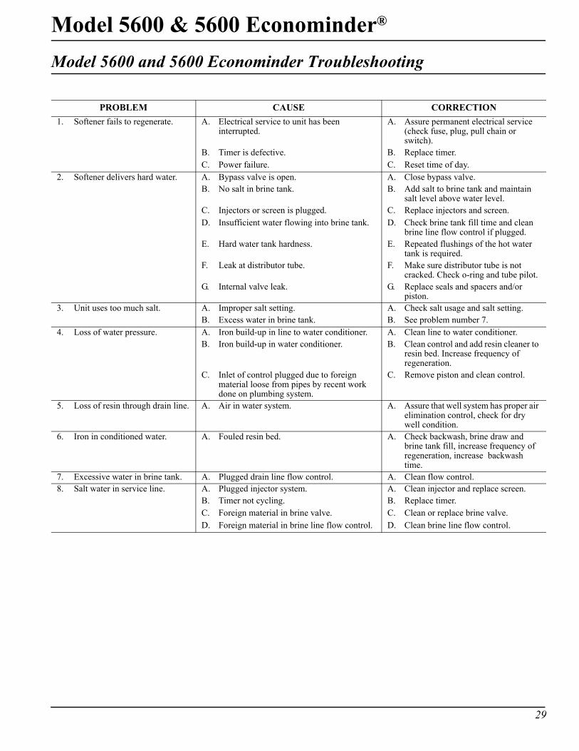
Model 5600 and 5600 Econominder Troubleshooting
PROBLEM CAUSE CORRECTION1. Softener fails to regenerate. A. Electrical service to unit has been
interrupted.A. Assure permanent electrical service
(check fuse, plug, pull chain or switch).
B. Timer is defective. B. Replace timer.C. Power failure. C. Reset time of day.
2. Softener delivers hard water. A. Bypass valve is open. A. Close bypass valve.B. No salt in brine tank. B. Add salt to brine tank and maintain
salt level above water level.C. Injectors or screen is plugged. C. Replace injectors and screen.D. Insufficient water flowing into brine tank. D. Check brine tank fill time and clean
brine line flow control if plugged.E. Hard water tank hardness. E. Repeated flushings of the hot water
tank is required.F. Leak at distributor tube. F. Make sure distributor tube is not
cracked. Check o-ring and tube pilot.G. Internal valve leak. G. Replace seals and spacers and/or
piston.3. Unit uses too much salt. A. Improper salt setting. A. Check salt usage and salt setting.
B. Excess water in brine tank. B. See problem number 7.4. Loss of water pressure. A. Iron build-up in line to water conditioner. A. Clean line to water conditioner.
B. Iron build-up in water conditioner. B. Clean control and add resin cleaner to resin bed. Increase frequency of regeneration.
C. Inlet of control plugged due to foreign material loose from pipes by recent work done on plumbing system.
C. Remove piston and clean control.
5. Loss of resin through drain line. A. Air in water system. A. Assure that well system has proper air elimination control, check for dry well condition.
6. Iron in conditioned water. A. Fouled resin bed. A. Check backwash, brine draw and brine tank fill, increase frequency of regeneration, increase backwash time.
7. Excessive water in brine tank. A. Plugged drain line flow control. A. Clean flow control.8. Salt water in service line. A. Plugged injector system. A. Clean injector and replace screen.
B. Timer not cycling. B. Replace timer.C. Foreign material in brine valve. C. Clean or replace brine valve.D. Foreign material in brine line flow control. D. Clean brine line flow control.
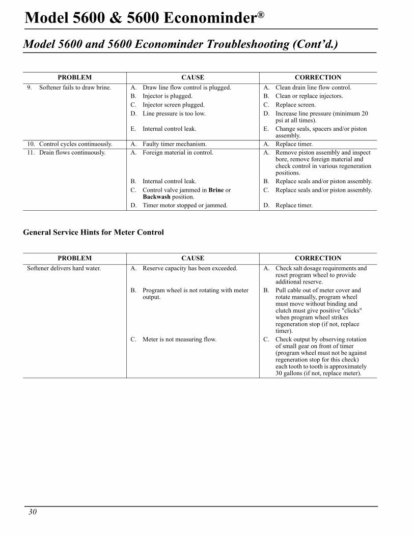
30
Model 5600 & 5600 Econominder®
Model 5600 and 5600 Econominder Troubleshooting (Cont’d.)
General Service Hints for Meter Control
PROBLEM CAUSE CORRECTION9. Softener fails to draw brine. A. Draw line flow control is plugged. A. Clean drain line flow control.
B. Injector is plugged. B. Clean or replace injectors.C. Injector screen plugged. C. Replace screen.D. Line pressure is too low. D. Increase line pressure (minimum 20
psi at all times).E. Internal control leak. E. Change seals, spacers and/or piston
assembly.10. Control cycles continuously. A. Faulty timer mechanism. A. Replace timer.11. Drain flows continuously. A. Foreign material in control. A. Remove piston assembly and inspect
bore, remove foreign material and check control in various regeneration positions.
B. Internal control leak. B. Replace seals and/or piston assembly.C. Control valve jammed in Brine or
Backwash position.C. Replace seals and/or piston assembly.
D. Timer motor stopped or jammed. D. Replace timer.
PROBLEM CAUSE CORRECTIONSoftener delivers hard water. A. Reserve capacity has been exceeded. A. Check salt dosage requirements and
reset program wheel to provide additional reserve.
B. Program wheel is not rotating with meter output.
B. Pull cable out of meter cover and rotate manually, program wheel must move without binding and clutch must give positive "clicks" when program wheel strikes regeneration stop (if not, replace timer).
C. Meter is not measuring flow. C. Check output by observing rotation of small gear on front of timer (program wheel must not be against regeneration stop for this check) each tooth to tooth is approximately 30 gallons (if not, replace meter).
Model 5600 & 5600 Econominder®
31
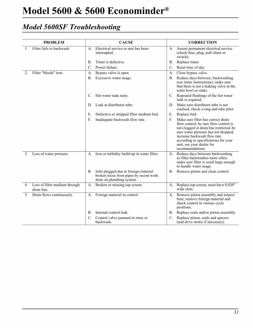
Model 5600SF Troubleshooting
PROBLEM CAUSE CORRECTION1. Filter fails to backwash. A. Electrical service to unit has been
interrupted.A. Assure permanent electrical service
(check fuse, plug, pull chain or switch).
B. Timer is defective. B. Replace timer.C. Power failure. C. Reset time of day.
2. Filter "bleeds" iron. A. Bypass valve is open. A. Close bypass valve.B. Excessive water usage. B. Reduce days between, backwashing
(see timer instructions), make sure that there is not a leaking valve in the toilet bowl or sinks.
C. Hot water tank rusty. C. Repeated flushings of the hot water tank is required.
D. Leak at distributor tube. D. Make sure distributor tube is not cracked, check o-ring and tube pilot.
E. Defective or stripped filter medium bed. E. Replace bed.F. Inadequate backwash flow rate. F. Make sure filter has correct drain
flow control, be sure flow control is not clogged or drain line restricted, be sure water pressure has not dropped, increase backwash flow rate according to specifications for your unit, see your dealer for recommendations.
3. Loss of water pressure. A. Iron or turbidity build-up in water filter. A. Reduce days between backwashing so filter backwashes more often, make sure filter is sized large enough to handle water usage.
B. Inlet plugged due to foreign material broken loose from pipes by recent work done on plumbing system.
B. Remove piston and clean control.
4. Loss of filter medium through drain line.
A. Broken or missing top screen. A. Replace top screen, must have 0.020" wide slots.
5. Drain flows continuously. A. Foreign material in control. A. Remove piston assembly and inspect bore, remove foreign material and check control in various cycle positions.
B. Internal control leak. B. Replace seals and/or piston assembly.C. Control valve jammed in rinse or
backwash.C. Replace piston, seals and spacers
(and drive motor if necessary).
32
Model 5600 & 5600 Econominder®
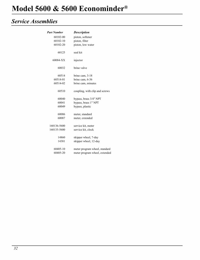
Service Assemblies
Part Number Description60102-00 piston, softener60102-10 piston, filter60102-20 piston, low water
60125 seal kit
60084-XX injector
60032 brine valve
60514 brine cam, 3-1860514-01 brine cam, 6-3660514-02 brine cam, minutes
60510 coupling, with clip and screws
60040 bypass, brass 3/4" NPT60041 bypass, brass 1" NPT60049 bypass, plastic
60086 meter, standard60087 meter, extended
160136-5600 service kit, meter160135-5600 service kit, clock
14860 skipper wheel, 7-day14381 skipper wheel, 12-day
60405-10 meter program wheel, standard60405-20 meter program wheel, extended

Model 5600 & 5600 Econominder®
33
Notes:
34
Model 5600 & 5600 Econominder®
Notes:


P/N 40106 Rev. H 05/05