Embed Size (px)
Citation preview

O W N E R ’ S H A N D B O O K : F R O N T I O R
w w w. a u t o - t r a i l . c o . u k
4187
10/
10 D
esig
ned
and
prod
uced
by
Kal-G
roup
T: +
44 (0
)142
7 61
0127
ww
w.ka
l-gro
up.c
o.uk
Auto-Trail VR Limited.Trigano House, Genesis Way, Europarc,Grimsby, North East Lincolnshire, DN37 9TU.Main Reception Tel +44(0) 1472 571000 Fax +44(0) 1472 571001www.auto-trail.co.ukParts Department Tel +44(0) 1472 571003 Fax +44(0) 1472 571002
4187 AT Frontier Cover +5mm spine:Layout 1 19/10/10 13:01 Page 2

www.auto-trail.co.uk
O W N E R S ’ H A N D B O O K
F R O N T I E R
T A K E Y O U R S O N A N A D V E N T U R E
4187 AT Frontier Owners Handbook REPRO v2:Layout 1 29/10/10 14:10 Page 1

T A K E Y O U R S O N A N A D V E N T U R E2
Important
Your Motorhome makes use of many complexsystems and services. Please ensure that youhave read all instruction manuals carefully, and fully understand all aspects of your vehicle, before driving it on the open road.If you have any queries on the operation ofany part of your Motorhome please contactyour supplying dealer.
4187 AT Frontier Owners Handbook REPRO v2:Layout 1 29/10/10 14:10 Page 1

3www.auto-trail.co.uk
Useful Information
Complete the details below:
Model:
Date Purchased:
Supplying Dealer:
Sales Person:
Telephone Number:
Tyre Pressure:
Radio Code:
Exterior Door Key Number:
Water Filter Key Number:
Vehicle Build Number:
Name: Telephone:
: OWNERS HANDBOOK
4187 AT Frontier Owners Handbook REPRO v2:Layout 1 29/10/10 14:10 Page 2

T A K E Y O U R S O N A N A D V E N T U R E4
Useful Information
Auto-Trail VR Limited.Trigano House, Genesis Way, Europarc,Grimsby, North East Lincolnshire, DN37 9TU.Tel: +44(0) 1472 571000 Fax: +44(0) 1472 571001e-mail: [email protected]
4187 AT Frontier Owners Handbook REPRO v2:Layout 1 29/10/10 14:11 Page 3

5www.auto-trail.co.uk
Contents
Useful information..................................................3-4
Introduction............................................................6-7
Preparing for the road............................................8-9
External features................................................10-11
Driving your Motorhome ........................................12
Selecting a pitch......................................................13
Gas services ......................................................14-15
Electrical services ..............................................16-17
Leisure battery ........................................................18
EC325 power supply unit ..................................18-19
EC500 power supply unit........................................20
EC480 Control Panel ........................................21-23
Entertainment system........................................24-25
Spinflo oven ......................................................26-27
Dometic RM8555 refrigerator ................................28
Thetford N97 fridge/freezer ....................................29
Truma S3002 vehicle space heater ..................30-31
Truma Combi 4E/6E ..........................................32-33
Truma Ultrastore water heater ................................34
Exterior BBQ ..........................................................35
Flue covers ..............................................................36
Water services ........................................................37
Thetford cassette toilet ..........................................38
Exterior shower ......................................................39
Windows & skylights..........................................40-41
Wind-out awning ....................................................42
Security & ventilation ........................................43-44
Habitation door ......................................................45
Central locking ........................................................46
Entrance step ..........................................................47
General care ......................................................48-49
Winter laying up ................................................50-51
Good neighbour guide ......................................52-53
Annual check list................................................54-57
Guarantee ..........................................................58-59
Tyre Pressure ..........................................................60
Vehicle Specification ..............................................61
Cable colour chart ..................................................62
230V circuits............................................................63
Road Lighting circuits ............................................64
Power circuits..........................................................65
Consumer circuits - roof ........................................66
Consumer circuits - floor ........................................67
: OWNERS HANDBOOK
4187 AT Frontier Owners Handbook REPRO v2:Layout 1 29/10/10 14:11 Page 4
T A K E Y O U R S O N A N A D V E N T U R E6
Introduction
Auto-Trail welcomes you to the ranks of Auto-Trail owners.
This handbook has been designed to enableyou to derive the maximum benefit andenjoyment from your motorhome; its information will be beneficial toexperienced and new motorhomers alike.
4187 AT Frontier Owners Handbook REPRO v2:Layout 1 29/10/10 14:11 Page 5

7www.auto-trail.co.uk
Introduction
This handbook is intended to give a brief overviewof your Motorhome and its appliances.
You are advised to read all of the individualappliance instructions which will be found inthe information wallet supplied with your vehicle.
Please note that every effort is made within thishandbook to accurately reflect and describe ourMotorhomes.
However, our policy of continued improvements,and change in market supply conditions meansthat we reserve the right to alter specificationswithout prior notice.
It is important that this handbook accompaniesthe Motorhome so that any future owner hasthe benefit of the relevant information.
Your Motorhome is designed to give many yearsof use. Regular maintenance is however necessaryto ensure trouble free service.
Your supplying dealer is responsible for all aspectsof customer care.
All vehicles are supplied with a comprehensivewarranty, please ensure that the dealer has fullyexplained all aspects of your Motorhomesoperational systems and the necessary servicingrequirements.
Should you require assistance your supplying dealeris fully conversant with the correct procedures thatyou should follow to get any issues dealt with in atimely manner.
Modifications To Your VehiclePlease check with your supplying dealer beforecarrying out any modifications to your vehicle.
Any unauthorised modifications carried out by athird party could effect the terms of your warrantyagreement.
We would always advise that you consult yourdealer before any additional equipment is fittedto your vehicle to ensure the appropriate fixingsupport is available.
Appliance MaintenanceIn the interest of safety, replacement parts foran appliance shall conform to the appliancemanufacturers specifications, and shouldbe fitted by him or his authorised agent.
Base VehiclePlease make reference to the base vehiclehandbook for matters relating to the Motorhomeas a road vehicle (e.g. tyre pressures, serviceintervals, etc...).
: OWNERS HANDBOOK
4187 AT Frontier Owners Handbook REPRO v2:Layout 1 29/10/10 14:11 Page 6

T A K E Y O U R S O N A N A D V E N T U R E
Preparing for the Road
Loading Your VehicleAll models manufactured by Auto-Trail are ofa well balanced design, the most commoncauses of poor stability include:
• Poor weight distribution of the weight inside the vehicle.
• Incorrect tyre pressure (always adhere tothe tyre pressures stated in the chassis manufacturers handbook. Always inflateto the ‘fully laden’ condition).
Try to load heavy items down near the floor ofthe vehicle, between the axles and as evenlyas possible side to side.
We would recommend that the table is storedon the floor between the beds if there is nodedicated storage position.
Where a dedicated storage position is available,the table should be retained in this positionwhilst the vehicle is in motion.
Roof Rack (If Fitted)Please be advised that the maximumrecommended weight that should be carriedon the roof rack is 40kg.
Please be aware that in certain conditions thefibreglass roof may become very slippery,please take extreme care should you chooseto walk on the vehicle roof.
Bicycle Carrier (If Fitted)Auto-Trail recommends that if a bicycle carrieris fitted to your vehicle it should be capable ofcarrying no more than two cycles.
The Frontier model is designed to accept aspecific model of cycle carrier details of whichare available through your supplying dealer.
Never exceed the maximum authorised weightthat should be specified on the carrier.
Tow BarsVarious suppliers manufacture tow bars that canbe fitted to your Auto-Trail vehicle. Please checkwith your tow bar supplier that the tow ball fittedto your vehicle fits your requirements exactlyand does not contravene any road trafficregulations.
8
4187 AT Frontier Owners Handbook REPRO v2:Layout 1 29/10/10 14:11 Page 7

9www.auto-trail.co.uk
Preparing for the Road
Maximum Loading Of Your VehicleThe weights of your vehicle are stated in the back ofthis handbook and on the secondary weight platelocated in the engine bay of your vehicle.
The secondary weight plate gives the followinginformation.
• The maximum authorised weight of your vehiclewhich must never be exceeded when the vehicleis loaded and in use.
• The gross train weight of your vehicle. This is the maximum combined weight of the actual Motorhome fully loaded to its maximum authorised weight, plus the allowance for a trailer. The weight of the loaded Motorhome and trailer must never exceed the gross train weight quoted on the weight plate.
• ‘1’ is the maximum authorised weight for the individual front axle.
• ‘2’ is the maximum authorised weight for the individual rear axle.
• ‘3’ is the maximum authorised weight of the individual third axle (only used on twin rearaxle models).
Please note that if you add both maximumauthorised axle weights together it will normallygive you a larger figure than the maximumauthorised weight – please be aware that theMaximum Authorised Weight must never be exceeded.
Please take care to ensure that you have allowedfor the masses of all items you intend to carry inthe Motorhome. e.g. passengers, optionalequipment, essential habitation equipment andpersonal effects such as clothing, food, pets,bicycles, sailboards, sports equipment, etc.
Before You Set Off In Your Motorhome• Ensure all articles are stowed securely.
Do not store tins, bottles or heavy items in overhead lockers.
• Close and secure all lockers and cupboard doors.
• Secure all bunks.
• Close and secure all roof lights.
• Store main table in transit position.
• Ensure fridge is on 12V operation and setdoor lock.
• Close and latch all windows (never drive with windows on night settings).
• Leave all curtains and blinds open to aide visibility.
• Ensure leisure battery is secure.
• Ensure all gas appliances are turned off, that the gas bottles are correctly positioned, secured and turned off.
• Ensure that seat swivels (if fitted) are locked inthe forward facing position.
• Ensure entrance step is retracted.
: OWNERS HANDBOOK
4187 AT Frontier Owners Handbook REPRO v2:Layout 1 29/10/10 14:11 Page 8

T A K E Y O U R S O N A N A D V E N T U R E10
External Features
FD
B
CA
A Exterior door retaining catch when open.
B Folding step.
C Fridge vents.
D Awning light (where fitted).
E Status T.V. aerial(omni directional, where fitted).
F Front marker lights.
E
4187 AT Frontier Owners Handbook REPRO v2:Layout 1 29/10/10 14:11 Page 9

11www.auto-trail.co.uk
External Features
G Spare wheel (Frontier only).
H External ladder.
J Lockable external access door to toilet waste tank.
K Rear marker lights.
L Lockable gas cylinder compartment (operated via an internal remote lever).
M High level brake light (where fitted).
H G
JL
MK
: OWNERS HANDBOOK
4187 AT Frontier Owners Handbook REPRO v2:Layout 1 29/10/10 14:11 Page 10

T A K E Y O U R S O N A N A D V E N T U R E12
Driving Your Motorhome
Driving Your MotorhomePulling AwayWhen pulling away in your Motorhome alwaysoperate the clutch smoothly, change gearssmoothly and try not to jerk the clutch.
Motorhome HandlingPlease remember that your Motorhome is muchlarger than a standard motor car when carryingout any manoeuvres.
• Allow longer to speed up when overtaking.
• Do not swing out suddenly.
• Carry out all manoeuvres as smoothlyas possible.
• Use the nearside wing mirror to check Motorhome has cleared obstaclewhen overtaking.
• Do not bump the kerbs with theMotorhome wheels.
• Reduce speed accordingly in strong winds, going downhill or in poor visibility.
• Large high speed vehicles cause air buffeting, extra care must be taken when passing or being passed by a high sided vehicle.
ReversingProficiency at reversing can only be achievedwith practice and we would recommend thatyou should first practice in a large open area.
As well as this courses are run by manyorganisations.
Reversing AidYour vehicle may be fitted with a visualreversing aid. This aid is designed to assista drivers attention only during reversing ofthe vehicle, they are not intended to replacea drivers self judgement. Auto-Trail will notaccept any responsibility for any accidentcaused by a drivers negligence.
Changing A Wheel• Ensure handbrake is fully applied and use
wheel chocks if necessary to ensure thevehicle cannot move.
• Remove the wheel trims (if fitted). Use the wheel-brace to slacken off wheel nuts onthe wheel to be changed.
• Position the jack under the axle or at the appropriate jacking point.
• Jack up the vehicle until the wheel to bechanged is just off the ground.
• Remove the wheel nuts and wheel.
• Fit the spare wheel (located in the carrier)and reverse the above procedure.
• Tighten all nuts equally.
4187 AT Frontier Owners Handbook REPRO v2:Layout 1 29/10/10 14:11 Page 11

13www.auto-trail.co.uk
Selecting A Pitch
Please note that under no circumstances shouldthe corner steadies be used to jack up the rearof the vehicle. Use a proprietary bottle jack orscissor jack that is capable of holdingthe weight of your fully loaded Motorhome.
Alloy Wheels / Tyre ValvesIt is vitally important that when you get replacementtyres fitted to your vehicle the valves that are usedare capable of withstanding the high pressuresassociated with Motorhome tyres.
Usually only ‘bolt through’ steel type valvescan withstand the high pressures associatedwith Motorhome tyres.
Driving AbroadPlease ensure that you are familiar with the relevantlaws and regulations that apply in the countries inwhich you choose to travel.
Different mainland European countries havedifferent laws and regulations and it is yourresponsibility to ensure that your vehiclecomplies with this regulations and thatyou drive within the law.
Selecting A PitchDo not pitch in a position in which your vehicle willobstruct others coming in.
Try to choose an area that is dry, reasonably leveland preferably with a hard base. If you have noalternative but to pitch on a slope, ensure thatwhen you leave you are driving down the slope.
It is always good practice to chock the wheelsof the Motorhome when parked on a slope ora slippery surface even when the brakesare applied.
In poor site conditions you are advised to tryto keep engine revs as low as possible to tryto avoid wheel spin and try to steer asstraight as possible.
Levelling The MotorhomeLevelling of the Motorhome on your chosen pitchmust be carried out in both directions for therefrigerator and other equipment to functioncorrectly. Levelling the Motorhome should becarried out using proprietary levelling ramps,or boards.
Rear Corner SteadiesYour Motorhome is fitted with rear cornersteadies which are used for stabilising yourMotorhome when stationary. These steadiesshould never be used to lift the rear wheels offthe ground, or as a jack.
OperationLower the corner steadies using the specialbrace supplied until they are in firm contact withthe ground. Levelling pads or boards should beused when the ground is soft or uneven.
In extreme cases where it is necessary to raisea wheel off the ground for levelling purposes,further support should be applied so that thecorner steadies do not take undue strain.
: OWNERS HANDBOOK
4187 AT Frontier Owners Handbook REPRO v2:Layout 1 29/10/10 14:11 Page 12

T A K E Y O U R S O N A N A D V E N T U R E14
Gas Services
The gas appliances in your vehicle are fed froma gas cylinder that is housed in a sealedcylinder compartment.
Gas flows from the gas bottles via a bulkheadmounted gas regulator. This regulator providesa working gas pressure of 30 m bar (1.5kg ofgas per hour).
All appliances installed by Auto-Trail aredesigned to work within this pressure range.
Please ensure that any additional appliances,not fitted by Auto-Trail, are capable of workingwithin this pressure.
Cylinder CompartmentYour vehicle is designed to accept either 15kgor 7kg gas cylinders, this is dependent on themodel you have chosen.
The compartment is accessed via a door onthe outside of the vehicle.
This door is secured by a remote cable releaselatch located behind the passenger seat insidethe vehicle.
The Compartment has low level ventilation toensure the safe operation of the cylinders andshould not be obstructed in any way.
Also please ensure that any additional items notspecified by Auto Trail that are stored in thiscompartment are secured correctly and cannotdamage any pipe work or fittings, or block theventilation.
Connecting / Changing A Gas CylindeBefore you can connect a gas cylinder to yourvehicle you will have to obtain the correct typeof high pressure hose for the type of bottle youhave chosen (different European countrieshave different connections). This hose shouldbe fitted to the bulkhead mounted gasregulator fitted inside your gas compartment.• Carefully position the gas cylinders into the
gas compartment locating the bottle into the retaining devices taking care not to damageany of the pipe work or fittings.
• Tighten the straps that will hold the cylinders firmly into the compartment.
• Connect the high pressure hose to the gas cylinder using a suitable tool. Please ensurethat the high pressure hose is connected correctly before opening the cylinder valve.
Gas HosesYour supplying dealer will advise on the correcttype of high pressure hose to connect your gascylinder to the pressure regulator.This will depend on the type of gas cylinders youhave chosen to carry in your vehicle.Inspect flexible hoses regularly for deteriorationand renew, as necessary with an approved type,in any case not later than the expiry date shownon the hose.Any hose that shows signs of damage orsplitting should be replaced immediatelyirrespective of its age.
4187 AT Frontier Owners Handbook REPRO v2:Layout 1 29/10/10 14:11 Page 13
15www.auto-trail.co.uk
Gas Services
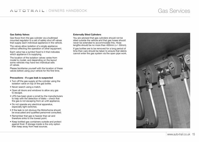
Gas Safety ValvesGas flows from the gas cylinder via a bulkheadmounted regulator to a set of safety shut off valvesthat supply each individual appliance in the vehicle.The valves allow isolation of a single appliancewithout affecting the operation of other equipment.Each valve has a symbol fixed to it that indicateswhich appliance it is supplying.The location of the isolation valves varies frommodel to model, and depending on the layoutsome vehicles may have two individual setsof valves.Please familiarise yourself with the location of thesevalves before using your vehicle for the first time.
Precautions - If a gas leak is suspected• Turn off the gas supply at the cylinder using the
isolation valve on top of the gas bottle.• Never search using a match.• Open all doors and windows to allow any gas
to escape.• LPG has been given a smell by the manufacturers
to help with the detection of leaks – check thatthe gas is not escaping from an unlit appliance.
• Do not operate any electrical apparatus,especially light switches.
• If the leak is not obvious the Motorhome should be evacuated and qualified personnel consulted.
• Remember that gas is heavier than air and therefore sinks to the lowest point.
• Keep bottled gas containers outside and protect against frost. If storage inside is the only option then keep away from heat sources.
Externally Sited CylindersYou are advised that gas cylinders should not besited outside the vehicle and that gas hoses shouldnever be extended to accommodate this. Hose lengths should be no more than 400mm (+/- 50mm).If gas bottles are to be removed for a long period oftime then care should be taken to ensure that debriscannot enter the gas system via the open pipe work.
: OWNERS HANDBOOK
4187 AT Frontier Owners Handbook REPRO v2:Layout 1 29/10/10 14:11 Page 14

T A K E Y O U R S O N A N A D V E N T U R E16
Electrical Services
All Auto-Trail vehicles have both a 12V and 230Velectrical system.The 12V electrical system is supplied by arechargeable leisure battery that is located ina dedicated battery compartment within thevehicle (locations of leisure batteries varies frommodel to model so please familiarise yourselfwith your battery location prior to using thevehicle for the first time).The leisure battery is charged either by thevehicle alternator when the engine is running,or by the on board battery charger when thevehicle is connected to a suitable mains supplyvia the hook-up lead supplied with the vehicle.Connection the mains supply also activates the230V sockets and 230V lights (where fitted toa vehicle), as well as various mains appliances.All Auto-Trail vehicles utilise a combined powersupply unit (PSU) that contains the batterycharger, 12V fuses, mains RCD (residual circuitbreaker) and MCB’s (miniature circuit breakers).Please familiarise yourself with the location ofthe PSU unit prior to using the vehicle for thefirst time (individual specifications of PSUunits will be described in more detail laterin this section).
Connecting The Vehicle To A Mains SupplyYour Auto-Trail vehicle is supplied with anorange mains hook-up cable that will connectyour Motorhome to a suitable power supplyon site via the mains hook-up point on yourMotorhome.
Mains hook-up points vary from model to modelso please familiarise yourself with your particularlocation prior to using your vehicle for thefirst time.Your Motorhome should only be connected to asupply that meets the requirements of BS7671.The site warden will hold information regardingthe suitability of supply.• Locate the charger power switch on the PSU
unit and switch to the ‘OFF’ position before connecting the mains supply.
• Connect the supplied hook-up cable (orange cable with blue connectors) to the Motorhome and then connect to the mains supply.
• Check the RCD operation by ensuring that the RCD is switched ‘ON’ (lever in up position). Press the ‘TEST’ button and confirm that the RCD is turned off (lever in ‘DOWN’ position).
• Switch the RCD back into the ‘ON’ position (lever in ‘UP’ position). If the button failed to operate the RCD seek professional advice from a qualified electrician.
• Check the polarity of the mains supply by locating the Reverse Polarity indicator and ensure that the indicator is not illuminated.If the indicator is illuminated seek advicefrom a professional electrician.
• Locate the MCB’s within the PSU (adjacentto the RCD) and ensure they are all in the ‘ON/UP’ position. If any MCB’s cannot be reset this could indicate a fault or an overloaded circuit.
4187 AT Frontier Owners Handbook REPRO v2:Layout 1 29/10/10 14:11 Page 15

17www.auto-trail.co.uk
Electrical Services
• Locate the power switch on the PSU and turnto the ‘ON’ position. The switch will illuminatewhen turned on.
It is now safe to check the operation of the 12Vand 230V equipment.
Overseas ConnectionsConnection to mains voltage overseas requiresparticular attention. Electricity supplies abroad maybe of reverse polarity. The significance of this is thatwhen an appliance is switched off, it may not be electrically isolated.It is useful to check the polarity of the supply so thatthe connection can be made neutral to neutral andlive to live as recommended. Your Auto-Trail,however, is fitted with a double pole circuit breaker.Check that all Motorhome equipment is set toaccept the site supply prior to switching it on.
Please note that if too many appliances are inoperation at one time, the MCB may trip. This isa safety measure. On some sites, the power isnot sufficient to power all appliances. If in doubt,consult the site manager or warden.
PSU Courtesy LightThe cupboard in which the PSU is situated isequipped with a courtesy light that is activatedwhen the cupboard door is opened. This light issupplied by the on board leisure battery of thevehicle when stationary. Should a fault occur on this circuit and the light fail, starting the engine will
reconnect the light to the vehicle battery circuit toallow fuses and Circuit Breakers to be checked, etc.
Wiring of connecting cable and Motorhomemains inlet:Pitch outlet supply
Cable plug
Cable coupler
Motorhome mains inlet
The cable plug is connected to the cable coupler bya 2.5mm flexible 3-core cable.
Warning:It is essential that connections are made exactlyas shown. If the terminal markings are not inaccordance with the diagram, they must beignored. If in doubt, consult a qualifiedelectrician.
GeneratorsIf a generator is fitted, the vehicle must be regularlyserviced to achieve the optimum performance.Engine speed is used to govern the output andfrequency of the unit in KW and Hz, and if this isallowed to vary beyond a safe level, permanentdamage could be caused to certain electronicequipment such as 12V chargers etc.
IMPORTANTPeriodically, preferably not less than once a year,the Motorhome electrical installation should beinspected and tested. A report on the conditionshould be obtained as described in theRegulations for Electrical Installations,published by the Institute of Electrical Engineers.It is important that the main switch at the sitepoint should be switched off, the supply flexiblecable disconnected and any cover replaced onthe socket outlet at the site supply point.It is dangerous to leave the supply flexiblecable connected.If a fault should develop with your electricalsystem that is not described in the ‘fault table’and your supplying dealer cannot resolve theproblem, Sargent Electrical Systems operate atelephone help line that is available duringnormal office hours.Tel: 01482 678981
Flexible wiring Fixed wiringBrown Live RedBlue Neutral Black
Green/Yellow Earth Green/Yellow
: OWNERS HANDBOOK
4187 AT Frontier Owners Handbook REPRO v2:Layout 1 29/10/10 14:11 Page 16

T A K E Y O U R S O N A N A D V E N T U R E18
Leisure Battery / EC500 Power Supply Unit
Leisure BatteryYour vehicle is equipped with a rechargeableleisure battery that is located in a dedicatedbattery compartment within your vehicle.
Locations of leisure batteries vary from modelto model, so please familiarise yourself with yourbattery location before using your vehicle for thefirst time. The battery is charged via the onboard charging unit when the vehicle is pluggedinto a mains supply, or via the vehicle alternatorwhilst your Motorhome is being driven.
Connecting and disconnecting the batteryPlease ensure that all cigarettes are extinguishedbefore working in the auxiliary batterycompartment.
Switch off all appliances and lamps beforedisconnecting the leisure battery.
• Release the battery securing bolts or securing straps from the leisure battery.
• Carefully remove the battery from the battery compartment (please take care – the leisure battery is extremely heavy).
• Release the battery terminals using a suitably sized spanner.
To refit the battery, simply reverse the aboveprocedure.
Please ensure the battery is located safely andsecurely before driving your Motorhome.
EC500 PSU (Power Supply Unit)OverviewThe EC500 Power Supply Unit utilises a batterycharger that supplies 12 volt DC power to runthe leisure equipment and supply the leisurebattery. It also houses the 12 voltDC fuses thatprotect the various 12volt circuits, and the230volt RCD and MCB’s that protect the variousmains circuits.
Residual Current Device & Miniture Circuit BreakersThe Residual Current Device is provided toprotect the user from a potentially lethal electricshock. The RCD will turn off (trip) if a faultoccurs on the system. To ensure the RCD isworking correctly, the test button should beoperated each time the vehicle is connected tothe mains supply.
The Miniature circuit breakers (MCB’s) operate in a similar way to traditional fuses and areprovided to protect the wiring from an overloador short circuit. If an overload occurs the MCBwill switch off the supply. If this occurs the causeof the fault should be investigated beforeswitching the MCB back on. Details of the MCBratings and the circuits they protect are detailedin the back of this handbook.
12 Volt DC FusesThese fuses are provided to protect the various 12 volt circuits from an overload or short circuit.
4187 AT Frontier Owners Handbook REPRO v2:Layout 1 29/10/10 14:11 Page 17

19www.auto-trail.co.uk
EC325 Power Supply Unit: OWNERS HANDBOOK
If a fuse does blow, the cause of the fault should beinvestigated before a replacement is fitted. Whenreplacing a fuse, always replace a fuse with thecorrect value. Never replace with a higher value asthis could damage the wiring harness. Details offuse ratings are in the back of this handbook.
Shutdown ButtonThe shutdown button is used to turn off the systemelectronics when they are not required to savebattery power. The unit should be turned ‘off’(button out) when the vehicle is being put intostorage or not being used for long periods of time.
Before using the system please ensure that thesystem shutdown button is in the ‘on’ position(button in).
Power ButtonThe Power button turns on the leisure power. Pressthe button once to turn on the 12 volt power – theLED will illuminate, press the button again to turn offthe 12 volt power - the LED will go out.
The power button must be in the ‘on’ position forany of the 12 volt systems to operate.
Pump ButtonThe pump button turns on the 12 volt water pumpcircuit. Press the button one to turn on the waterpump - the LED will illuminate, press the buttonagain to turn off the pump – the LED will go out.
Light ButtonThe light button turns on the main internal 12 voltlights. Press the button once to turn on the mainlights – the LED will illuminate, press the buttonagain to turn the lights off – LED will go out.
Battery Select ButtonThis button allows you to select which battery isused as the power source for the vehicle, or whichbattery is being charged by the on board chargingsystem if connected to the mains supply. Thecontrol panel will automatically select the leisurebattery when the 12 volt system is turned on. Thebattery select button must be pressed to manuallyselect the vehicle battery, the selected battery willbe shown on the EC480 control panel.
Reverse Polarity IndicatorThis light is designed to illuminate when the live andneutral mains input supply has been reversed(crossed over). If the light illuminates then there is aproblem with either the site supply or the cableconnecting the supply to your vehicle.
Please note that if you choose to use your vehiclewith a generator this could also illuminate thereverse polarity indicator. This is a normal side effectwhen using some types generator and does notnecessarily indicate a fault. Please refer to yourgenerator handbook for further information.
4187 AT Frontier Owners Handbook REPRO v2:Layout 1 29/10/10 14:11 Page 18

T A K E Y O U R S O N A N A D V E N T U R E20
EC500 Power Supply Unit
Charger ButtonThe charger button turns on the internal batterycharger that will charge the batteries and provide 12 volt power to the interior of the vehicle. Theswitch will illuminate when the switch is pushedin and the vehicle is connected to the mainssupply.
Space Heater SwitchThe space heater switch will isolate the mainssupply to the space heater when the vehicle isplugged into a suitable 230 volt supply. Pressthe button once to turn the supply on – thebutton will stay in and the button will illuminate,press the button again to turn the supply off, the light will go out.
Water Heater SwitchThe water heater switch will isolate the mainssupply to the water heater when the vehicle isplugged into a suitable 230 volt supply. Pressthe button once to turn the supply on – thebutton will stay in and the button will illuminate,press the button again to turn the supply off, the light will go out.
Cautionary NoteApart from the changing of fuses and the testing and resetting of the RCD and MCB’s nomaintenance is required on the PSU unit. If aproblem develops with your unit please contact your supplying dealer or a qualified electrician.
4187 AT Frontier Owners Handbook REPRO v2:Layout 1 29/10/10 14:11 Page 19

21www.auto-trail.co.uk
EC480 Control Panel
EC480 Control PanelThe LCD control panel controls all of the on board12 volt systems. The Panel is normally located overthe entrance door.
Basic Controls of the EC480 Control PanelPower ButtonUse the power button to turn the 12 volt power onand off inside the vehicle. Pressing the button oncewill turn on the 12 volt power; pressing the buttonagain to turn the power off. The adjacent LED willilluminate to indicate the power is turned on and thevoltage of the selected battery will be displayed onthe screen.
Pump ButtonWith the 12 volt power turned on, pressing thisbutton will turn the water pump on and off. Pressingthe button once will turn the water pump on;pressing it again will turn the pump off. The LEDadjacent to the button will illuminate to indicate thatthe pump is turned on.
Light ButtonWith the 12 volt power turned on, pressing thisbutton will turn on and off the main lighting insidethe vehicle. Pressing the button once will turn themain lighting on; pressing it again will turn the lightsoff. The LED adjacent to the button will illuminate toindicate that the main lights are on.
Awning LightWith the 12 volt power turned on, pressing thisbutton will turn on and off the exterior awning light.Pressing the button once will turn the light on;pressing it again will turn the light off. The LEDadjacent to the button will illuminate to show thatthe awning light is turned on.
Light Dimming ButtonWith the 12 volt power and main lights turned on,pressing the dimming button will adjust the lightlevel of the lights on the dimming circuit.
Battery SelectWhen the 12 volt power is turned on the leisurebattery is automatically selected as the powersource for the vehicle when no mains supply ispresent. If a mains supply is available then this is thebattery that will be charged by the on board batterycharger. Pressing the battery select button willchange the selected battery from the leisure batteryto the vehicle battery. The ‘active’ battery level isshown on the LCD screen – the letter ‘L’ indicatesleisure battery, the letter ‘V’ indicates vehicle battery.
Frost protection buttonIf your vehicle is fitted with optional water tankheaters pressing this button will turn on the watertank heating system. The LED adjacent to thebutton will illuminate to indicate the tank heatingsystem on.
: OWNERS HANDBOOK
4187 AT Frontier Owners Handbook REPRO v2:Layout 1 29/10/10 14:11 Page 20
T A K E Y O U R S O N A N A D V E N T U R E22
EC480 Control Panel
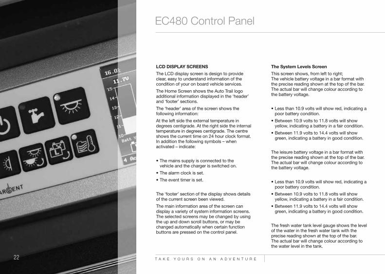
LCD DISPLAY SCREENSThe LCD display screen is design to provideclear, easy to understand information of thecondition of your on board vehicle services.
The Home Screen shows the Auto Trail logoadditional information displayed in the ‘header’and ‘footer’ sections.
The ‘header’ area of the screen shows thefollowing information:
At the left side the external temperature indegrees centigrade. At the right side the internaltemperature in degrees centigrade. The centreshows the current time on 24 hour clock format.In addition the following symbols – whenactivated – indicate:
• The mains supply is connected to the vehicle and the charger is switched on.
• The alarm clock is set.
• The event timer is set.
The ‘footer’ section of the display shows detailsof the current screen been viewed.
The main information area of the screen candisplay a variety of system information screens.The selected screens may be changed by usingthe up and down scroll buttons, or may bechanged automatically when certain functionbuttons are pressed on the control panel.
The System Levels ScreenThis screen shows, from left to right;The vehicle battery voltage in a bar format withthe precise reading shown at the top of the bar.The actual bar will change colour according tothe battery voltage.
• Less than 10.9 volts will show red, indicating apoor battery condition.
• Between 10.9 volts to 11.8 volts will showyellow, indicating a battery in a fair condition.
• Between 11.9 volts to 14.4 volts will showgreen, indicating a battery in good condition.
The leisure battery voltage in a bar format withthe precise reading shown at the top of the bar.The actual bar will change colour according tothe battery voltage.
• Less than 10.9 volts will show red, indicating apoor battery condition.
• Between 10.9 volts to 11.8 volts will showyellow, indicating a battery in a fair condition.
• Between 11.9 volts to 14.4 volts will showgreen, indicating a battery in good condition.
The fresh water tank level gauge shows the levelof the water in the fresh water tank with theprecise reading shown at the top of the bar. The actual bar will change colour according tothe water level in the tank.
4187 AT Frontier Owners Handbook REPRO v2:Layout 1 29/10/10 14:11 Page 21

23www.auto-trail.co.uk
EC480 Control Panel: OWNERS HANDBOOK
• With the tank 25% full the display will show red.
• With the tank 50% full the display will show yellow
• If the tank is over 75% full the display will show green.
The waste water tank level gauge shows the level ofthe water in the fresh water tank with the precisereading shown at the top of the bar. The actual barwill change colour according to the water level in the tank.
• With the tank 25% full the display will show green.
• With the tank 50% full the display will show yellow
• If the tank is over 75% full the display will show red.
The Active Battery ScreenThis screen is automatically selected when thebattery select button is operated. The batterysymbol on the bottom left of the display will containthe letter ‘L’ if the leisure battery is selected and aletter ‘V’ if the vehicle battery is selected.
This screen shows, from left to right;
The active battery voltage of the selected battery ina bar format with the precise reading shown at thetop of the bar. The actual bar will change colouraccording to the battery voltage.
• Less than 10.9 volts will show red, indicating apoor battery condition.
• Between 10.9 volts to 11.8 volts will show yellow,indicating a battery in a fair condition.
• Between 11.9 volts to 14.4 volts will show green,indicating a battery in good condition.
The calculated Leisure Battery capacity as apercentage in ‘amp hours’ is shown when theleisure battery is selected. This gauge shows thepredicted charge capacity of the battery, it willincrease as the battery is charged and decrease as the battery is discharged.
The solar panel ammeter shows the current in ampsthat is being provided by the solar panel if fitted tothe vehicle.
The battery ammeter shows the current in amps thatis going into, or discharging from the selected or‘active’ battery. A positive reading indicates that thebattery is being charged and is shown by a greenbar. A negative reading indicates that the battery isbeing discharged and is shown by a yellow bar -indicating a low discharge, or red – indicating a high discharge.
System Warnings ScreensThe system can display a number of warningscreens that will beep and display the appropriatemessage. Pressing the ‘select’ button will cancel the warning.
Please note these are only the basic menu controlson the panel. More in depth information can beobtained by reading the full instruction manualsupplied in the information wallet supplied with your vehicle.
4187 AT Frontier Owners Handbook REPRO v2:Layout 1 29/10/10 14:11 Page 22

T A K E Y O U R S O N A N A D V E N T U R E24
Entertainment System
Entertainment SystemOverviewThe entertainment system is equipped with aradio, DVD or CD player and a digital televisionreceiver. The images can be viewed on a 15 inchLCD monitor that allows you to watch either theDVD or Digital Television. It also incorporates anight vision colour reversing camera to aid yourreversing of the vehicle.
Please note that not all functions displayed onthe user interface are available on your Auto-Trailvehicle. The three functions available are; DigitalTelevision, DVD or CD and radio.
More detailed instructions can be found in theseparate instruction book supplied with yourvehicle.
Remote Controls• The system uses two remote controls.
• The remote control for the Radio / Digitaltelevision head unit.
• The remote control for the TFT LCD monitor.
The Radio / DVD Head UnitThis unit operates as a standard radio or CDplayer with the ability to play DVD discs. It alsoincorporates a digital television receiver thatallows you to view free to air digital televisiontransmissions. The unit has a touch screeninterface that allows you to access variousfunctions directly by touching the screen,alternatively you can use the remote controlsupplied.
To operate the unit turn it on by pressing thepower button on either the head unit or on theremote control.
Accessing the system menu via the touch screenAccess the menu by either tapping the touchscreen in the top left corner or by pressing the‘menu’ button on the remote control. Tap therelevant symbol on the touch screen to go to therelevant function required. Alternatively, pressingthe ‘SRC’ button on the remote controlrepeatedly will scroll through the variousfunctions. The on-screen display will show thefunction selected.
Radio operationAccess the menu screen by either tapping thetouch screen in the top left corner or by pressingthe ‘SRC’ button on the remote control.Press the ‘radio’ symbol on the touch screen,then select the radio station required and adjustthe volume as normal.
4187 AT Frontier Owners Handbook REPRO v2:Layout 1 29/10/10 14:11 Page 23

25www.auto-trail.co.uk
Entertainment System
To load a DVD or CDPress the eject button on the control panel along the bottom of the touch screen, the facia front will fold down.Insert a CD or DVD, the front will close automaticallyand the disc will load.Play the disk using the usual functions on theremote control.
Ejecting a diskTo eject a disk press the ‘eject’ button on the remotecontrol or on the bottom of the touch screen facia,the disk will eject. The facia front has to be closedmanually by pressing the ‘eject’ button on thebottom of the facia.
Digital Television and Flat Screen monitor isolator switchThe LCD monitor and digital television receiver arepowered by the on board 12 volt power supply(PSU) which is located in the PSU locker. Ensurethat the 12 volt supply us turned on at the controlpanel.An isolator switch is located close to the PSU thatwill cut the 12 volt power to the monitor and headunit. To view either the digital television or DVD onthe fold down monitor this switch must be in the‘on’ position.Remember; always press this switch to the ‘off’position if leaving the vehicle for a prolongedperiod of time to stop the leisure battery beingdischarged to dangerous levels.
To watch digital televisionEnsure that the TV antenna is in the up position andswitched on, the red LED will illuminate on TV booster.Turn on the head unit with the power button on thefacia or on the remote control. Tapping the facia front in the top left corner willactivate the menu screen on the head unit. Touchthe screen ‘DBB-T’ icon and the digital televisionreceiver will activate. Alternatively, pressing the‘SRC’ button repeatedly on the remote control willscroll through the various functions. Stop when thedisplay shows ‘DVB-T’.
Tuning in the digital receiverIf the tuner is not tuned to the local transmitter ‘no channel’ will appear on the screen.Press the ‘Menu’ button on the remote control ortouch the bottom left of the screen – the ‘search’screen will appear on the unit.Select ‘search’ either by pressing enter on theremote control or by tapping the symbol on thetouch screen.Select ‘Automatic Search’ by either pressing ‘enter’on the remote control or by tapping the symbol onthe touch screen.The display will indicate the channels found whichwill be stored automatically into the tuner.Please note that this operation will need to becarried out every time you move into a new digitaltransmission area.
To view a DVD or Digital Television on the dropdown monitorThe DVD or Digital Television picture willautomatically appear on the fold down FTF monitorif the isolator switch is turned to the ‘on’ positionand the screen is in the lowered position.If you want to turn off the head unit monitor whilstviewing the fold down TFT, this can be achieved bypressing and holding the ‘SRC’ button along thebottom of the head unit.
Reversing cameraOn the rear of your vehicle there is a night visioncamera installed.To operate the unit select the reverse gear and themonitor in the dashboard radio will display theimage direct from the reversing camera.
Note: The reversing camera fitted to this vehicleshould be treated as aide to your reversing. Auto Trail VR Limited will not be held responsiblefor any accidents caused by driver carelessness.
: OWNERS HANDBOOK
4187 AT Frontier Owners Handbook REPRO v2:Layout 1 29/10/10 14:11 Page 24

T A K E Y O U R S O N A N A D V E N T U R E26
Spinflo Oven
Spinflo OvenThe Spinflo is fitted with three gas burners, one230V hotplate and gas oven.
The gas burners are fully adjustable betweensimmer and full flame, and the oven rangesfrom 130˚C to 240˚C.
The electric hotplate has six temperaturesettings.
The oven, grill and burners operate off the onboard LPG supply, the 230V electric hotplatecan only be used when the vehicle is pluggedinto a 230V electrical supply.
Gas OperationBefore operating the appliance on gas ensurethat the valve on the gas cylinder open and thatthe individual safety valve for the oven is open.
Hinged Glass LidPlease note that the hinged glass lid must bein the upright ‘OPEN’ position whilst usingthe oven.Please ensure that all burners and hotplatesare turned off before closing the lid.
Using The Hotplate Gas BurnersTo Light• Push in the control knob and rotate to the
highest setting.
• Press the electronic igniter on the oven faciato light the burner. If the burner has not lit within 15 seconds the control knob shouldbe released and the burner left for at least1 minute before a further attempt to lightthe burner is made.
To Turn OFF• Turn the control knob until the line on the
control knob is aligned with the dot on the control panel.
• Always ensure that the control knob is in the ‘OFF’ position when you have finished using the hotplate burners.
Using The Electric HotplateBefore using the electric hotplate, ensure thatthe vehicle is plugged into a 230V electricalsupply and that the isolation switch is inthe ‘ON’ position.
4187 AT Frontier Owners Handbook REPRO v2:Layout 1 29/10/10 14:11 Page 25

27www.auto-trail.co.uk
Spinflo Oven
Switching ON• The hotplate control is numbered from 1 to 6.
• To turn it on rotate the knob either clockwise or anti-clockwise to the required position.
• Position ‘1’ is the coolest setting, position ‘6’ isthe hottest.
Switching OFFTo turn off the hotplate, rotate the knob until the lineor pointer on the knob lines up with the zero on thecontrol panel.
Using The GrillPlease note that the grill must only be used withthe grill door open and the heat deflector belowthe facia pulled out.
To Light• Open the grill door.
• Push in the control knob and turn to thehighest setting.
• Press the electronic igniter on the oven facia tolight the grill burner. If the burner has not lit within 15 seconds the control knob should be released and the burner left for at least 1 minute before a further attempt to light the burner is made.
To Turn OFF• Turn the control knob until the line on the control
knob is aligned with the dot on the control panel.
• Always ensure that the knob is in the off position when you have finished grilling.
Using The Oven
To Light• Push in the control knob and turn to gas mark ‘9’.
• Press the igniter on the oven facia to lightthe oven.
• If the burner has not lit within 15 seconds the control knob should be released and the burner left for at least 1 minute before a further attemptto light the burner is made.
• Set the control knob to the desired temperature setting.
To Turn OFFTo turn off the oven, rotate the knob until the lineon the control knob is aligned with the dot onthe control panel.
: OWNERS HANDBOOK
4187 AT Frontier Owners Handbook REPRO v2:Layout 1 29/10/10 14:11 Page 26

T A K E Y O U R S O N A N A D V E N T U R E28
Dometic RM8555 Refrigerator
Dometic RM8555 RefrigeratorThis refrigerator is designed to be used on 230V,12V (DC) or LPG. The desired power option canbe selected either manually or automatically viathe control panel on the refrigerator.
Switching on the refrigeratorEnsure that the valve on the gas cylinder is fullyopen and that the isolation valve to therefrigerator is in the open position. Pleasefamiliarise yourself with the location of thesevalves before using your vehicle for the first time.
1 = Power On switch / Energy selector switch(MODE)
2 = Temperature selection
3 = Door opening (only when equipped withelectrical door lock)
4 = Indicator LED failure
5 = Indicator LED door lock (optional)
6 = Indicator-LED / operating mode display
7 = Temperature level display
Turning on the Refrigerator - Automatic energy selection
To turn on the refrigerator press button ‘1’ for 3seconds, the display will show the previouslyselected operating mode,
e.g. 230 which means 230V. By pressing button‘1’ again you can change the operating mode to;
• AU – automatic energy selection
• 230V, 12V, GAS – manual energy selection.
Please note the selected power source must beavailable otherwise a fault code will appear onthe display.
Manual energy selectionBy pressing button ‘1’ repeatedly turn off theautomatic energy selection mode and willilluminate the desired energy source in themanual mode, e.g. ‘GAS’, ‘230’ or ‘12V’.
Setting the refrigerator temperaturePressing button ‘2’ on the control panel willadjust the temperature of the refrigerator. Theminimum setting is indicated at the bottom ofthe display, the highest at the top. Please notethat the highest setting indicates the lowestrefrigerator temperature.
Turning off the refrigeratorPressing and holding button ‘1’ will turn off the refrigerator.
For further detailed instructions contact the fullinstruction manual supplied in the informationwallet supplied with your vehicle.
4187 AT Frontier Owners Handbook REPRO v2:Layout 1 29/10/10 14:11 Page 27

29www.auto-trail.co.uk
Thetford N97 Refrigerator
Thetford N97 RefrigeratorThese refrigerators are designed to be usedon 230V, 12V (DC) or LPG.
Switching On The RefrigeratorEnsure that the valve on the gas cylinder isfully open and that the isolation valve to therefrigerator is in the open position.
Please familiarise yourself with the locationof these valves before using your vehicle forthe first time.
Press the main switch to turn on the appliance.The function LED will turn blue and all symbolson the LCD display will light up.
Use the mode selector switch to select either the‘AUTO’ function, or alternatively the desired powersource of your choice. The LCD will show you thepower source that you have selected.
Set the desired refrigerator cooling level by meansof the cooling level selection switch. The LCDpanel will show you the cooling level that youhave selected.
Manual Energy SelectionPressing the mode selector switch will scroll throughthe power options available; 12V, 230V and gas.Select the power source required and the LCDdisplay will show the power source that you haveselected. If the selected power source is unavailablethe LED will start flashing every second to indicate afault on the unit.
Switching Off The RefrigeratorTo switch off the refrigerator press the main powerswitch ‘A’, the blue LED will go out. The refrigeratoris now switched ‘OFF’.
: OWNERS HANDBOOK
4187 AT Frontier Owners Handbook REPRO v2:Layout 1 29/10/10 14:11 Page 28

T A K E Y O U R S O N A N A D V E N T U R E30
Truma S3002 Vehicle Space Heater
Vehicle Space Heater - Truma S3002The S3002 heater incorporates a 3kw gasburner and a 2kw mains electric element(known as Ultraheat).
If the two energy sources are usedsimultaneously this gives a maximum heatoutput of 5kw. The heater also incorporatesa 12V blown air heat distribution system that willdeliver warm air through blown air ducts runningthroughout the vehicle.
Igniting The HeaterBefore operating the heater for the first timeensure that the batteries are fitted to the ignitionunit, and that the gas cylinder, and isolationvalve are turned on.
• Turn on the control knob to the desired thermostat setting (from 1 to 10) andpress down as far as the stop.
• Ignition will take place automatically untilthe flame ignites. Keep the control knob pressed down for a further ten secondsto allow the safety pilot to operate.
• If the flame should go out then automatic ignition will occur immediately during the closing time of the safety pilot (approximately 30 seconds). If there is no flame present the igniter will continue to operate until the control knob is switched to ‘0’.
4187 AT Frontier Owners Handbook REPRO v2:Layout 1 29/10/10 14:11 Page 29

31www.auto-trail.co.uk
Truma S3002 Vehicle Space Heater
Truma Ultraheat - 230V Mains OperationBefore switching on ensure that the electrical fusespur protecting the Ultraheat is in the ON position.
The position of this switch varies from modelto model so please familiarise yourself withthe location of this switch before using yourvehicle for the first time.
• To switch the unit on turn the rotary outer switch to the desired heat output level - 500W, 1000W or 2000W.
• Set the central thermostat knob to the desired room temperature (1 to 9). The actual setting of the thermostat must be determined individually depending on the heating requirements for each customer.
• To switch the unit off rotate the outer switch to the off (0) position.
Trumavent Blown Air Heating SystemThe Trumavent Blown Air System distributes warmair through the blown air ducting throughout thevehicle.
• Set the rotary control on top of the S3002to either manual or automatic setting.
• On the manual setting the speed of the blownair fan is controlled via the central controlknob that gives settings from 1 to 5,(5 being the highest).
• On automatic setting the heat output is steadily adjusted to the respective heat emission fromthe heater. The maximum setting of the fancan be set by the central control knob andthe output will vary between this value andthe slow running setting.
• To turn off the blown air system rotate the outer control to the central OFF position.
Manual AutomaticOff
: OWNERS HANDBOOK
4187 AT Frontier Owners Handbook REPRO v2:Layout 1 29/10/10 14:11 Page 30

Truma Combi 4E / Truma Combi 6EThe Combi E Gas Heater is a warm air heaterwith an integrated hot water boiler. The unit canoperate on liquid gas (LPG) or 230V mainselectricity. The heater can be used in ‘winter’mode that will produce warm air heating and hotwater, and ‘summer’ mode that will produce hotwater only.Before operating the heater for the first timeensure that the 12V system is turned ‘ON’ on thecontrol panel over the doorway, and that the gascylinder, and isolation valve are turned on. To use the heater on 230V the Motorhome mustbe plugged into the mains supply, with theisolation switch in the ‘ON’ position.
Power Selector Switch
A Power selection rotary switch.B Electric operation 230V, 1800W.C Electric operation 230V, 900W.D Gas operation.E Mixed operation*
(gas and 900W electrical operation).
F Mixed operation*(gas and 1800W electrical operation).
G Yellow LED on = “Electrical operation”
Position “E” and “F” should only be used in ‘winter’ mode.
Control Panel
H Rotary switch for room temperature (1 – 5).
K Green LED lit “Operating”Green LED flashing = unit “after running”to reduce the units temperature.
L Summer operation(water temperature either 40˚ or 60˚ ).
M Winter operation (heating without hot wateror water system drained).
N Winter operation (heating with hot water).
O Rotary “OFF” switch.
P Yellow LED lit – boiler heat up phase.
R Red LED lit, red LED blinking = failure of heater to ignite.
Please note that all LEDs are only visiblewhen the unit is switched on.
T A K E Y O U R S O N A N A D V E N T U R E32
Truma Combi 4E / 6E
ABCDE
FG
LOMN
KP, R
H
4187 AT Frontier Owners Handbook REPRO v2:Layout 1 29/10/10 14:11 Page 31

Summer Operation(Supplying Hot Water Only)• Select gas or electrical operation with the power
selector switch. The yellow LED will illuminate onthe switch to indicate the unit is operating on 230V.
• Move the rotary switch on the control panel toposition ‘L’ (summer operation) 40o or 60o and the yellow LED (P) should illuminate.
• When the selected water temperature is reachedthe heater will shut down and the LED (P) will go out.
Winter Operation(Supplying Blown Air Heating With Hot Water)• Select gas, electrical or mixed operation using the
power switch. The yellow LED (G) on the powerselector switch will illuminate to indicate 230Voperation.
• Move rotary switch on control panel to position (N).
• Set the rotary switch (H) to the desired thermostatsetting (1-5) The green LED (K) will illuminate toshow the unit is operating. The yellow LED (P) willindicate the waters heat up phase. When the roomtemperature selected on the control panel isreached, the heater will switch back to its lowestoutput and will heat the water to 60˚. Once thewater temperature is reached the heater willswitch off and the yellow LED (P) will go out.
Supplying Blown Air Heating Without Hot Water• Select gas, electrical or mixed operation using the
power selector switch. The yellow LED (G) willilluminate to indicate 230V operation.
• Move the rotary switch on the control panel toposition (M)
• Set the rotary switch (h) to the desired thermostatsetting (1-5) The green LED (K) will illuminate toshow the unit is operating. The yellow LED (P) willonly illuminate if the water temperature is below5oC. When the room temperature selected on thecontrol panel is reached, the heater will switch off.The warm air fan will continue to operate at slowspeed until the temperature of the outgoing airfrom the heater has reached 40o.
• If the boiler is filled, then it will be automaticallyheated. The water temperature is totallydependant on the heat output giving off heatingand the duration of the time taken to reach thedesired room temperature.
Switching OFFSwitch off the heater at control panel using rotaryswitch (Position O). The green LED (K) will go out.
Please note that the if the green LED (K) blinksafter switching off then the unit is ‘after running’to reduce the units temperature. This will stopafter a few minutes and the green LED (K) will go out.
Filling The Unit With Water• Ensure that the cold water drain tap is closed
(lever should be in horizontal position – seedraining the water system).
• Turn on the hot tap in either the bathroom orkitchen (if your vehicle is fitted with a mixer tapplease set this to the ‘hot’ position.
• Switch on the water pump on the control panelover the doorway.
• Leave the tap open to let air escape from thewater system while the tank is filling. The heater is full when water flows out of the tap.
For more detailed information on operating theCombi Boilers please refer to the Truma ApplianceInstructions that can be found in your blueinformation wallet supplied with your vehicle.
Please note that when a space heater is used for the first time, or after a period of prolongedinactivity, it may smell slightly until any residualdust inside the heater has dissipated.
33www.auto-trail.co.uk
Truma Combi 4E / 6E: OWNERS HANDBOOK
4187 AT Frontier Owners Handbook REPRO v2:Layout 1 29/10/10 14:11 Page 32

T A K E Y O U R S O N A N A D V E N T U R E34
Truma Ultrastore Water Heater
Truma Ultrastore Water HeaterThe Truma Ultrastore water heater has a 10 litrecapacity that operates on either LPG, or whereavailable, 230V electric.
Filling The Ultrastore With WaterEnsure that the cold water drain tap is closed -lever should be in horizontal position – see draining the water system.
• Turn on the hot tap in either the bathroomor kitchen - if your vehicle is fitted with amixer tap please set this to the ‘HOT’ position.
• Switch on the water pump on the controlpanel over the doorway.
• Leave the tap open to let air escape fromthe water system while the tank is filling.
• The heater is full when water flows out ofthe tap.
Turning On The Ultrastore Gas Operation• Remove the external flue cover.
• Ensure the valve on the gas cylinder is in the open position and that the safety valve for the water heater is open.
• Select the required water temperature on the control panel (which is normally located over the entrance door) which is variable from 30˚to 70˚ centigrade.
• Switch on the water heater with the external rotary switch – the green operation lightwill illuminate.
If for whatever reason the boiler does not lightthe green LED will turn red. If this happensswitch off the appliance, wait 5 minutes thenswitch on again.
230V OperationTo use the water heater on 230V mains simplyturn the clearly marked switch into the ‘ON’position. The switch is clearly marked withan ‘ULTRASTORE’ label.
The position of this switch can vary from modelto model so please familiarise yourself with thelocation of this switch before using yourvehicle for the first time.
Please note, when the water heater is usedon mains the temperature is fixed toapproximately 70˚ centigrade, this isnot adjustable.
4187 AT Frontier Owners Handbook REPRO v2:Layout 1 29/10/10 14:11 Page 33

35www.auto-trail.co.uk
Exterior BBQ
Exterior BBQYour vehicle may be fitted with an external barbecuepoint that will allow you to use an LPG barbecuefrom the on board gas bottles.
The barbecue point is located behind a hinged flap,normally on the passenger side of the vehicle.
The exact location of the barbecue point varies fromvehicle to vehicle so please familiarise yourself withits’ location before using your vehicle for thefirst time.
The gas supply to the barbecue outlet can bestopped by an isolation valve located insidethe vehicle (valve is clearly marked ‘BBQ’).
This safety valve enables the barbecue pointto be isolated from the gas supply from insidethe vehicle.
Hose ConnectionYour vehicle will have been supplied with an adapterthat must be fitted to a suitable length of approvedlow pressure gas hose. The other end of this hoseshould be connected to your chosen LPG barbecue.
Please note - the Motorhome works at aregulated gas pressure of 30 m bar.
Please note all gas connections should only beundertaken by a competent person.
Connecting The Hose To The Vehicle• Ensure the barbecue appliance is turned ‘OFF’
and the gas isolation tap inside the vehicleis turned ‘ON’.
• Align the tabs on the barbecue connector to the corresponding slots in the socket in the side of the vehicle.
• Rotate the barbecue connector 90˚ as indicated on the connector, this will lock the connector into the side and start the gas flow to the barbecue.
• Use your barbecue as per yourmanufacturers’ instructions.
Disconnecting The Barbecue FromThe Vehicle• Ensure the barbecue is turned ‘OFF’.
• Rotate the connector through 90˚ as indicated on the connector. This turning action will turn off the gas supply and allow the connector to be removed.
: OWNERS HANDBOOK
4187 AT Frontier Owners Handbook REPRO v2:Layout 1 29/10/10 14:11 Page 34

T A K E Y O U R S O N A N A D V E N T U R E36
Flue Covers / Water Services
Flue CoversThe Refrigerator and Truma Ultrastore waterheater fitted to your vehicle are supplied withflue covers that are designed to keep out waterand debris if the vehicle is to be stood unusedfor any length of time.The flue covers must be removed before theappliances are used as the covers will stopcombustion air entering the appliance andthe flue gasses escaping if left in place.
Refrigerator Flue CoversThe type of refrigerator fitted to your vehicle willdetermine the type of flue cover fitted.There are two types of fastener; a 90˚ turn buttonthat is operated either with a coin or screwdriver(fitted to Dometic appliances), or simply a clip-off cover that has two tabs that need tobe released, again using a flat screwdriver(fitted to Thetford appliances).Replacing the cover is a reversal of theabove procedures.
Truma Ultrastore Flue CoverThe Ultrastore water heater flue cover isremoved by pulling the bottom of the coveraway from the vehicle.This pulling action will unclip the cover from thebottom and allow it to rotate upwards to bereleased from the vehicle.Replacing the cover is a reversal of theabove procedure.
Water ServicesFresh Water TankYour vehicle has an on board fresh water tankthat allows you to carry fresh water with you onyour journey. This tank supplies all of the watersystems inside your vehicle. The volume of thefresh water tank will vary depending on whichmodel you have chosen. Water is pumped from the on board tank by aself priming and cancelling automatic pumpthroughout the vehicle.The pump is fitted with an in-line filter to ensuretrouble free running. This must be cleanedperiodically to ensure that there is no reductionin flow. The pump automatically pressurisesthe water system to a pre-determined waterpressure, when a tap is opened water flowsfrom it and the pump switches on to maintainthe pre determined pressure. When the tap isswitched off the pump will continue runninguntil the correct pressure in the system isreached, it will then shut down.The pump circuit is controlled by the isolationswitch on the control panel. Always switch offthe pump at the control panel when leavingthe vehicle.
Please note that if the pump runs on for morethan 5-10 seconds after you have closed allthe taps, it is possible that there could be aleak in the system. This should be checkedimmediately.
4187 AT Frontier Owners Handbook REPRO v2:Layout 1 29/10/10 14:11 Page 35

37www.auto-trail.co.uk
Water Services
Filling The Fresh Water TankThe tank is filled via a lockable water inlet onthe outside of your vehicle.This inlet is identified by a blue tap symbol adjacentto it, (either a blue label or a blue moulding on thefiller itself).The location of the water inlet will vary from vehicleto vehicle so please familiarise yourself with itslocation before using your vehicle for the first time.Before attempting to fill your fresh water tank pleaseensure that the cold water drain tap inside thevehicle is in the closed position (see ‘draining thewater system’ section).
To Fill• Remove the cap and insert a suitable length
of pipe.• Connect the other end to a clean water supply.• Fill the tank until either the water level gauge
reads 100%, or until the tank begins to overflow.
• Remove the hose. Replace the cap, lock and remove the key.
Please note, use only food or drug quality pipe.
Waste Water TankAll waste water (excluding the toilet) is piped into an onboard waste water tank locatedunderneath your vehicle. The volume of the wastewater tank will vary depending on which model youhave chosen.When the waste tank becomes full (which will beindicated by a visible and audible signal on controlpanel), the tank should be emptied via the drainvalve on the outside of the vehicle over a suitabledrainage point.When the ‘tank full’ indicator sounds there will stillbe some capacity in the waste tank, but we wouldadvise that it is emptied as soon as possible.
: OWNERS HANDBOOK
4187 AT Frontier Owners Handbook REPRO v2:Layout 1 29/10/10 14:11 Page 36
T A K E Y O U R S O N A N A D V E N T U R E38
Thetford Cassette Toilet
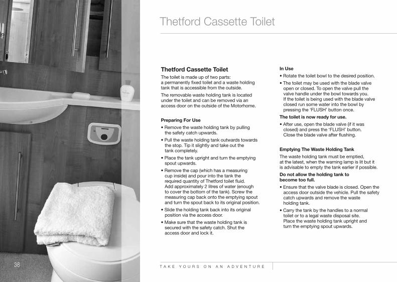
Thetford Cassette ToiletThe toilet is made up of two parts:a permanently fixed toilet and a waste holdingtank that is accessible from the outside.
The removable waste holding tank is locatedunder the toilet and can be removed via anaccess door on the outside of the Motorhome.
Preparing For Use• Remove the waste holding tank by pulling
the safety catch upwards.
• Pull the waste holding tank outwards towards the stop. Tip it slightly and take out thetank completely.
• Place the tank upright and turn the emptying spout upwards.
• Remove the cap (which has a measuringcup inside) and pour into the tank therequired quantity of Thetford toilet fluid.Add approximately 2 litres of water (enoughto cover the bottom of the tank). Screw the measuring cap back onto the emptying spout and turn the spout back to its original position.
• Slide the holding tank back into its original position via the access door.
• Make sure that the waste holding tank is secured with the safety catch. Shut theaccess door and lock it.
In Use• Rotate the toilet bowl to the desired position.
• The toilet may be used with the blade valve open or closed. To open the valve pull the valve handle under the bowl towards you.If the toilet is being used with the blade valve closed run some water into the bowl by pressing the ‘FLUSH’ button once.
The toilet is now ready for use.• After use, open the blade valve (if it was
closed) and press the ‘FLUSH’ button.Close the blade valve after flushing.
Emptying The Waste Holding TankThe waste holding tank must be emptied,at the latest, when the warning lamp is lit but itis advisable to empty the tank earlier if possible.
Do not allow the holding tank tobecome too full.• Ensure that the valve blade is closed. Open the
access door outside the vehicle. Pull the safety catch upwards and remove the wasteholding tank.
• Carry the tank by the handles to a normaltoilet or to a legal waste disposal site.Place the waste holding tank upright andturn the emptying spout upwards.
4187 AT Frontier Owners Handbook REPRO v2:Layout 1 29/10/10 14:11 Page 37

39www.auto-trail.co.uk
Exterior Shower
• Remove the emptying spout cap. Hold the waste holding tank by the upper handle nearest to the emptying spout. Hold the rear handle with your other hand so that you can operate the vent plunger with your thumb.Keep the vent plunger pressed to ensure thatthe tank is emptied without splashing.
Please note that the vent plunger should onlybe pressed when the emptying spout ispointing downwards.After emptying, flush the tank and clean theblade valve thoroughly with water. Replace thespout cap and slide the waste holding tank backinto the toilet and close the door.
Exterior ShowerYour vehicle may be fitted with an exterior showerthat uses water from the onboard water tank ofyour Motorhome.
This shower can be used for washing mud off;shoes, boots etc.
The location of the exterior shower will varydepending on the particular model that youhave chosen.
Please familiarise yourself with the location of theconnection before using your vehicle for thefirst time.
Connecting The ShowerThe exterior shower hose supplied with your vehiclehas the shower connector already fitted, no furtherconnections are required.
• Lift the hinged cover on the outside of the vehicle to reveal the hose connection in the side ofthe vehicle.
• Align the tabs on the shower hose connector with the slots in the side of the vehicle and rotate in the direction shown on the actual hose connector. This rotating action turns on the water supply and allows the temperature to be adjusted to your exact requirements.
• The actual shower head has a release trigger to start the water flow. This trigger must be squeezed and held to use the shower. Releasing the trigger will stop the water flow from the hose.
Disconnecting The Shower• Rotate the hose connector fixed into the side of
the vehicle to the ‘OFF’ position. This will turn off the water supply and allow the hose to be removed from the vehicle.
• Close the hinged flap on the side of the vehicle.
: OWNERS HANDBOOK
4187 AT Frontier Owners Handbook REPRO v2:Layout 1 29/10/10 14:11 Page 38

T A K E Y O U R S O N A N A D V E N T U R E40
Windows & Skylights
Windows & SkylightsYour vehicle is fitted with side windows and skylights to provide light and ventilation to yourvehicle. The number of windows and skylightsfitted will depend on the particular model thatyou have chosen.
WINDOWS & BLINDSAll windows fitted to the habitation area of yourmotorhome are of acrylic construction and openeither by means of a top hinge or a slide,depending on the location in the vehicle.
Top hung windows are opened by rotating thetwo catches 90o to release from the lockingplate, the window will then hinge outwards onthe top hinge. The window can be held in theopen position by means of the locking collar onthe telescopic arm. Sliding windows are openedby releasing the retaining catch and sliding thewindow in its track.
Please ensure all windows are fully closed andlocked before driving your vehicle away.
Window BlindsThe habitation widows are fitted with springloaded night blinds and fly screens. The flyscreens pull down from the top of the blind, thenight blinds pull up from the bottom.
Always ensure that the blinds are in the fullyopen position before driving your vehicle.
4187 AT Frontier Owners Handbook REPRO v2:Layout 1 29/10/10 14:11 Page 39

41www.auto-trail.co.uk
Windows & Skylights
SKYLIGHTSYour vehicle is fitted with skylights in the ceiling toallow light and ventilation into the vehicle.
Opening the skylightsThe clear transparent skylights are opened byfolding out the winding handle in the inner frameand rotating anti clockwise to release the lockingclamps. Continue winding anti clockwise and theglazed dome will hinge upwards to the desiredamount.
Closing skylightsRotate the winding handle clockwise until the glazeddome is fully closed. Line up the handle with therecess in the inner frame and fold the handle away.
Please ensure all skylights are fully closed andlocked before driving your vehicle away.
OmniventThe omnivent can be opened for additionalventilation by rotating the turn mechanism in aclockwise direction; the glazed dome will hingeopen. Winding the mechanism anti clockwise willclose the glazed dome.
Blinds & Fly screensThe clear skylights are fitted with night blinds and fly screens. The blinds and fly screens workindependently of each other by pulling them acrossfrom the ends of the inner frame and clipping themtogether. The desired night blind or fly screen canthen be fully drawn across the whole aperture.
Opening the blinds and fly screens is a reversal ofthe above procedure.
Please note that all pleated night blinds should notbe left in the ‘fully closed’ position if the vehicle isbeing left in storage for any period of time.
: OWNERS HANDBOOK
4187 AT Frontier Owners Handbook REPRO v2:Layout 1 29/10/10 14:11 Page 40

T A K E Y O U R S O N A N A D V E N T U R E42
Wind-Out Awning
Wind-Out AwningYour vehicle may be fitted with a wind-outawning which, when extended, will providea shaded area next to your Motorhome.
OperationWinding Out The Awning• Locate the winding handle into the socket
on the left hand side of the awning.
• Turn the winding handle clockwise –the awning will start to open after approximately two turns.
• Continue winding. When the awning has extended to approximately 1 metre stop winding and lower the supporting legs from the awning and adjust the length of the legs until they come into contact with the ground.
• Continue unrolling the blind until it isfully extended.
• Adjust the height / position of the supporting legs to ensure that the blind fabric is taught and allowing water to run off in the eventof rain – remove the winding handle.
• We would recommend that the support legs are pegged into the ground.
• On vehicles fitted with either the 4 metre or4.5 metre awnings a central support raftercan be inserted between the awning case (fitted to the vehicle) and the awning facia(the section that winds out) to addextra stability.
Winding In The Awning• Remove the central support rafter if fitted.• Insert the winding handle into the socket
and turn anti-clockwise – the awning willstart to retract (the legs, if pegged intothe ground, should be released).
• When the awing is retracted to within 1metre of the vehicle the supporting legscan be folded back into the awning facia.
• Continue winding anti-clockwise until the awning snaps back fully into the awningbox – continue winding slowly until thehandle stops as this engages the locking mechanism of the awning.
• Remove the winding handle.
Please note that the awning is designed tobe a sun shade and not as rain protection.The awning should be closed in the likelihoodof high winds, storm, snow or heavy rain.
4187 AT Frontier Owners Handbook REPRO v2:Layout 1 29/10/10 14:11 Page 41
43www.auto-trail.co.uk
Security & Ventilation
Awning Space LPG Appliance ExhaustNo danger is caused if the LPG exhaust from therefrigerator vents into an enclosed awning.If totally enclosed, space heaters may produceenough exhaust fumes to pollute an enclosedawning to levels of discomfort.In extreme cases carbon monoxide could build upto reach dangerous levels. You are advised to allowsome additional ventilation when such appliancesare in use.
VentilationLow level ventilation is provided via the entrancestep well. High level ventilation is provided byskylights located in the roof of your vehicle.
All ventilation complies with European Standardsand vents should not be obstructed in any way asthis could lead to insufficient fresh air.
If this occurs then the confined atmosphere canbecome deficient in oxygen which can lead to abuild up of the highly dangerous gas carbonmonoxide (Co). Carbon monoxide is colourless,odourless and tasteless and if allowed to build upwill rapidly cause unconsciousness, and even death.
There is no danger providing all ventilation is notblocked in any way and all meshes are regularlycleaned using a vacuum cleaner.
Roof Mounted Flue InstallationsAll flue installations should be inspected forcorrosion once a year throughout their length.
If any sign of perforation is detected, the flue shouldbe replaced. Ensure the replacement flue is of thecorrect type and that it is installed by anapproved engineer.
Combustible MaterialsCare should be taken when storing any combustiblematerials near any source of heat (e.g. space heater)as these surfaces can become very hot during useand any guards or grills may not give full protection,particularly to the young or elderly.
Portable HeatersNever use portable cooking or heating appliancesother than electric heaters that are not of the directradiant type, to heat your vehicle as it can be a fireand asphyxiation hazard.
Under no circumstances should a cookingappliance be used for heating the vehicle.
WarningPlease note that internal socket outlets shouldonly be used with dedicated appliances.No appliance should be used outside theMotorhome whilst connected to aninternal socket.
Fire And Safety PrecautionsIn Case Of FirePlease read all warning notices inside your
Motorhome advising you on fire prevention,ventilation and what to do in the event of a fire.
If a fire should develop in your vehicle pleaseobserve the following;
• Get everybody out of the Motorhome as quickly as possible.
• Call the fire brigade.
• Turn off the gas bottle isolation valve if safe todo so.
• If possible and safe to do so, remove the gas cylinders and place some distance away fromthe vehicle.
• If it is an electrical fire, always turn off the supply as quickly as possible.
• Only tackle the fire only if you deem it safe todo so.
Fire ExtinguisherYour vehicle is fitted with a fire extinguisher for usein the event of an emergency.
The location of the fire extinguisher will vary frommodel to model so it is important that youfamiliarise yourself with its location before usingyour vehicle for the first time.
Please refer to the instructions printed on the actualextinguisher for guidance as to the correct use ofthe unit, and the maintenance schedule thatshould be adhered to.
Please ensure that you are confident as to thelocation and operation of the fire extinguisherbefore using the vehicle for the first time.
: OWNERS HANDBOOK
4187 AT Frontier Owners Handbook REPRO v2:Layout 1 29/10/10 14:11 Page 42

T A K E Y O U R S O N A N A D V E N T U R E44
Security & Ventilation
Smoke DetectorsYour vehicle is fitted with a battery operatedsmoke alarm that will emit a loud pulsating toneshould smoke be detected in your vehicle.
Operating The Smoke AlarmOnce the battery is connected a small indicatorlight (LED) positioned near the test buttonshould flash approximately once every minute.This indicates that the alarm is operatingnormally.
Testing Your Smoke AlarmIt is recommended that you test your smokealarm once a week to ensure the detector isworking correctly.
• Push and hold the ‘TEST’ button for approximately 3 seconds.
• A loud pulsating alarm should sound to indicate the detector is functioning correctly.
• During the alarm test the LED indicator will flash quickly.
Maintaining your smoke alarmIf the smoke alarm emits a short beep once aminute the battery is at the end of its life andshould be replaced immediately, this low voltagewarning will sound for approximately 7 days.
We would always recommend that the battery isreplaced at least every 12 months to ensure
correct operation. If the LED indicator does notflash every minute then the battery should bereplaced immediately as this will indicate thatthe battery is completely flat.
Clean your smoke alarm regularly to preventdust build up. This can be done using a vacuumcleaner with a brush attachment.
Escape PathsIt is important that you do not block any escapepaths or emergency exits with any obstructionsthat could hinder your escape in an emergency.
Please familiarise yourself with the designatedemergency exits in your vehicle before using itfor the first time.
Children & PetsDo not leave children or pets in an unattendedMotorhome as they could be exposed tohazards that could cause an accident.
Upper BunksCare should be taken against the risk of fallingout when this bunk is used by children.We would advise that the upper bunks arenot suitable for children under six years ofage without supervision.
4187 AT Frontier Owners Handbook REPRO v2:Layout 1 29/10/10 14:11 Page 43

45www.auto-trail.co.uk
Habitation Door
SecurityAt Auto-Trail we have tried to go further than anyother Motorhome manufacturer to protect yourinvestment. Make it difficult for the thieves byprotecting your Motorhome and its contents.
Always lock all doors and windows when leavingyour vehicle, even if it is left for a short periodof time.
Motorhome TheftThe theft of a Motorhome can occur in the mostunlikely circumstances; from a motorway servicearea, or even from an owners’ drive.
Make sure all windows and doors are secured evenif only leaving the vehicle for a short time and wewould advise that you do not leave valuables ineasily visible positions inside the vehicle.
Habitation DoorThe habitation door in your vehicle utilises a twopoint locking system that is operated eitherautomatically by the vehicle central lockingsystem, or manually by the door key.It can also be locked from the inside thevehicle by a locking tab.
Manually Locking The Habitation DoorFrom Inside The VehicleTo lock the habitation door from the inside simply push down the locking button on the inner door handle.
Manually Unlocking The Habitation Door From Inside The VehicleTo unlock the door from the interior pull the release handle towards you. The locking button will springout, the door will be unlocked and the door will open.
Manually Locking The Habitation Door FromOutside The VehicleThe habitation door can be locked from outside thevehicle using the habitation key.
Simply turn the key clockwise to engage the lock,return the key to the vertical position then withdrawthe key.
Please note that locking the habitation door withthe key will not activate the central locking tothe vehicle cab doors.
Locking The Door With The Central LockingPlease refer to the Central Locking section.
: OWNERS HANDBOOK
4187 AT Frontier Owners Handbook REPRO v2:Layout 1 29/10/10 14:11 Page 44

T A K E Y O U R S O N A N A D V E N T U R E46
Central Locking
Central LockingYour vehicle may be fitted with a central lockingsystem that links the locking of the rearhabitation door to the base vehicle cab doors.
The central locking can be activated by eitherthe remote key fob, the locking switches on thedashboard (base vehicle dependant) or manuallyby the key.
Locking / Unlocking With TheRemote Key-FobThe Fiat key has three buttons that lock andunlock the various entrance doors onthe vehicle.
• Pressing button ‘A’ will unlock the base vehiclecab doors only.Please note that the habitation door lock will give an audible click, but willnot unlock.
• Pressing button ‘B’ will lock both the base vehicle cab doors and the rear habitation door.
• Pressing button ‘C’ will unlock the rear habitation door only. Please note that the base vehicle cabdoors will give an audible click, but willnot unlock.
Locking / Unlocking With TheDashboard SwitchesWhen inside the vehicle the entrance doors canbe locked or unlocked via the two switches onthe Fiat dashboard.
• Pressing button ‘A’ will lock all entrance doors (and the LED will illuminate).
• Pressing button ‘B’ will unlock all entrance doors (LED will go out).
A
B
C
BA
4187 AT Frontier Owners Handbook REPRO v2:Layout 1 29/10/10 14:11 Page 45

47www.auto-trail.co.uk
Entrance Step
Locking / Unlocking With Either The Cab KeyOr Habitation KeyLocking or unlocking the drivers’ door will only lockor unlock the driver and passenger door, it will notlock or unlock the habitation door. This must belocked or unlocked independently using either thekey or key fob.
Locking or unlocking the habitation door with thekey will only lock or unlock the habitation door, thecab doors must be locked or unlockedindependently with either the key or key fob
Entrance StepYour vehicle may be fitted with an electric entrancestep that is designed to assist you when enteringand exiting your Motorhome.
The step can be operated automatically with thecentral locking system, or manually via a buttonlocated next to the habitation entrance door.
The step will automatically fold away when theengine starts to minimise the risk of injury when the vehicle is in motion.
Operating The Step ManuallyThe step is operated manually by depressing thestep button located next to the habitationentrance door.
Pushing the button once will fold the step out,pressing it again will fold the step in.
Operating The Step With The Central Locking• Unlocking either the cab doors or the habitation
door with the remote key fob will fold the step out.
• Locking the doors with the remote key fob will fold the step in.
• Unlocking the vehicle from the internal dashboard switches will fold the step out.
• Locking the vehicle from the internal dashboard switches will fold the step in.
: OWNERS HANDBOOK
4187 AT Frontier Owners Handbook REPRO v2:Layout 1 29/10/10 14:11 Page 46

T A K E Y O U R S O N A N A D V E N T U R E48
General Care
Motorhome ExteriorThe exterior of Auto-Trail Motorhomes arefinished with a highly polished fibreglass skin.
This is a very durable surface and is very easyto clean due to its high gloss finish.
To maintain a showroom finish, wash theMotorhome regularly with a mild detergent,rinse off with cold water and leather off.A good quality car wax may be applied whichwill make washing even easier in the future.
Abrasive cleaning agents must never be usedto clean the exterior of Auto-Trail Motorhomes.
Within the first twelve months cracks andblisters can appear in the surface of mouldedGRP components. These are cosmetic onlyand have no effect on the vehicles structure.
These components can be readily repairedusing the correct procedure (please refer thisto your supplying dealer).
MouldingsAll mouldings are powder coated aluminium andwill retain their colour and finish for a long time ifno abrasive materials are used to clean them.
Care Of WindowsThe windows in your vehicles are fully doubleglazed and with care will remain sparkling andscratch free.
Clean your windows as you would your car.Do not use a sponge on dirty windows.When all dirt has been removed, dry with aleather or ‘vyleda’ type cloth. The catchesand stays do not need lubricating.
Tar can be removed using a proprietary tarremover which is available from most caraccessory shops.
Do not use petrol or other chemicalswithout approval.
It is a popular misconception that acrylicMotorhome windows are vacuum sealed,this is not so. The windows in a Motorhome can, as with domestic glazing, be susceptibleto temporary condensation if the temperaturedifference between inside and outside changesquickly and / or dramatically i.e. if a coldMotorhome is heated quickly using the heater or by the sun.
These drastic changes of temperature and themoisture in the air both contribute towards thetemporary condensation that will normallydisappear as quickly as it appears.
This whole phenomenon is purely related toambient temperature changes of theMotorhome compared to the window cavities.
4187 AT Frontier Owners Handbook REPRO v2:Layout 1 29/10/10 14:11 Page 47

49www.auto-trail.co.uk
General Care
Condensation
Condensation occurs when warm moist air meetsa cold surface. The risk of condensation thereforedepends upon how moist the air is and how cold theinternal surfaces of the vehicle are.
Condensation is normally more noticeable during thewinter months as the Motorhome is cold and becauseskylights, windows and doors are opened less meaningthat the moist internal air cannot escape.
How to try to minimise the likelihood ofcondensation occurring
To try to minimise the risk of condensation occurring it isimportant to try to maintain some level of ventilation.Your vehicle complies with EN721: 1988 which statesthe minimum requirements for high and low levelventilation, it is very important that these are notblocked or reduced in any way.
Try to provide reasonable heating.
If possible use the electric element of the space heaterwhen washing, cooking or drying damp clothes,particularly if the windows show signs of misting up.
Try to make sure all areas are at least partially heated,condensation most often occurs in unheated areas. Toprevent condensation the heat has to keep the roomsurfaces reasonably warm.
It can take a long time for a cold Motorhome to warm upso it is better to have a small amount of heat for a longperiod rather than a lot of heat for a short time. AMotorhome that have been left unoccupied of longperiods of time can become very cold. Wheneverpossible it is best to put the heating on at a low levelbefore setting off on a journey in the winter to pre heatthe vehicle.
Even in a well insulated Motorhome with correctventilation it is likely during cold weather if thetemperature is less than 10oC that condensation willoccur. Ideally the temperature should be kept at about20oC although this is not always possible.
Motorhome Interior Side Walls, Roof Lining and Furniture
A simple wash with a damp cloth and a mild detergentis all that is necessary.
Soft Furnishings
Carpets should be vacuumed occasionally to removegrit and sand. This helps maintain good appearance andensure long life.
The upholstery can be cleaned with a mild reputableupholstery cleaner.
It is recommended that curtains be dry cleaned.
Leather Upholstery
As leather is 100% natural product, some variation intexture and grain may be evident in the seat covers ofyour vehicle.
Caring for Leather
Avoid exposing leather to direct sunlight for prolongedperiods, and keep away from strong heat sources. Avoidyour furniture getting damp, and clean any spillsimmediately. Sharp objects could tear, scratch andscore leather.
Cleaning
Once a month, wipe with a damp cloth and drythoroughly with a towel. Once a year (or as required)apply a leather cream as per the manufacturer’sinstructions to keep the leather supple.
Please Note
We do not recommend that you sleep on any leathercovered upholstery, for this reason these beds havebeen fixed and will not pull-out.
Cupboard Catches
It is advisable to lightly oil cupboard catches,sliding bolts and hinges from time to time.
Vanity Unit / Shower Cubicle
Your vehicle is fitted with a plastic vanity bowl. Do notpour very hot water into it as it is made from a mouldedpolymer that may deform, always put cold water in first.
Care Of Plastic Components
The cleaning of any plastic components in the vehicle,e.g shower tray, should only be undertaken with mildsoapy water. General household cleaning productsshould not be used as they may cause the plastic to go brittle and crack.
Auto-Trail will not be held responsible for anyreplacement if it is suspected that this was the case.
Plated Fittings
These should never be cleaned using abrasive cleaners.Clean with a damp cloth and polish with a dry cloth only.
Natural Wood Worktop Edges
Should your vehicle worktop edges show signs of thelacquer breaking down, they should be re-sealed usinga proprietary yacht varnish, (or equivalent).
: OWNERS HANDBOOK
4187 AT Frontier Owners Handbook REPRO v2:Layout 1 29/10/10 14:11 Page 48

T A K E Y O U R S O N A N A D V E N T U R E50
Winter Laying Up
Whether you use your Motorhome all year roundor lay it up for the winter, care should always betaken to ensure your investment is receiving thevery best attention.
The following tips will be helpful for the periodswhen your Motorhome is not regularly used.
It applies if you store in a compound awayfrom home, or in your own drive.
TyresCare should be taken to ensure that your vehicleis not stored with slightly deflated tyres as thiscould cause damage to the side walls that couldlead to an accident when driving at speed.
Ideally you should rotate your wheels everycouple of weeks to try to eliminate flatspots developing.
Water SystemIt is important that the water system is drainedoff during the winter months to avoid freezingwhen the Motorhome is not in use or after thelast trip of the season. Failure to do this couldresult in serious damage to components.
To Drain Off• Open the drain valve on the fresh water tank
to ensure it is fully empty.
• Open the drain valve on the waste tank to ensure it is fully empty, (only drain into a suitable container).
• Open all taps inside the vehicle andleave open.
• Open the drain valve inside the vehicle to empty the water heater and empty the pipe work inside the vehicle.
• Allow the vehicle to drain in this way for five minutes, then run the pump to ensure it isfree of water.
• Empty cassette toilet, (see manufacturers instructions).
4187 AT Frontier Owners Handbook REPRO v2:Layout 1 29/10/10 14:11 Page 49

51www.auto-trail.co.uk
Winter Laying Up
Soft Furnishings / FurnitureIt is recommended that the upholstery is removedfrom the vehicle if at all possible during winterstorage to avoid damp. If this is not possible then itshould be stood on its end to allow as much air aspossible to circulate.
Leave all cupboard doors open to allow themaximum amount of air to circulate aroundthe vehicle.
Window BlindsWindow night blinds should not be left in the‘closed’ position for long periods as this mayaffect their folding back into the ‘open’ position.
Bringing Your Vehicle Out Of StorageBefore starting to use your Motorhome after a longstorage period we would recommend that you haveall gas and 230V electrical services checked by acompetent person.
We would recommend that the water system isflushed through with a sterilising solution priorto the first use of the Motorhome.
: OWNERS HANDBOOK
4187 AT Frontier Owners Handbook REPRO v2:Layout 1 29/10/10 14:11 Page 50

T A K E Y O U R S O N A N A D V E N T U R E52
Good Neighbour Guide
Motorhome Owners’ GoodNeighbour CodeAt A Camp Site On ArrivalPark as close to the reception area aspossible and report your arrival. Do not drive to a pitch and park unlessdirected by reception staff.
Vehicle Movement Around The SiteAlways keep to the site roads unless directedotherwise. Obey the speed limits, these aregenerally 10 mph.
Please note that stopping distances on grassare greater than on a normal road. You musthave a current valid driving license to drivea vehicle on site roads. Park where directedon your pitch. Where possible you shouldleave approximately 6m of free spacearound your vehicle.
Using Site Appliances• Connect all mains hook-ups correctly and
carefully.• Turn off all fresh water taps completely.• Use facilities such as toilets and showers
with care and consideration, leaving themin a tidy condition.
• Young children should be escorted and supervised.
Disposing Of WasteIf your vehicle is not fitted with a wastewater tank, place a suitable container underall waste water outlets.• Do not allow these to overflow.• Make sure you empty the containers at
appropriate waste water points. • Empty chemical toilets only where directed.• Avoid damage to sewerage treatment works
by using only approve chemicals.Phenols, coal tar or caustic based fluidsmust never be used under any circumstances.
• Solid bulky items such as disposable nappies etc. must not be put into the chemical closet emptying point or site rubbish bins.Wrap them in a polythene bag and place in designated containers.
• Household rubbish should be put into the private rubbish collection bins.
Noise PollutionPlease show consideration by thinking how thenoise you create will affect those around you.Open and close doors quietly.Control noise made by your children: do notallow them to play with kites, model aircraft,catapults or airguns close to vehicles.Do not allow them to play loud, boisterousballgames.Keep volume turned down on CD players,personal stereos radios and TVs. Do not playmusical instruments so loudly that they willupset your neighbours.
4187 AT Frontier Owners Handbook REPRO v2:Layout 1 29/10/10 14:11 Page 51

53www.auto-trail.co.uk
Good Neighbour Guide
If you have a power generator, make sure it isadequately silenced and use it with consideration,especially after dark.
PetsMost site operators do not object to well behavedpets but they should be kept well under control.• No animal should be allowed to run loose on
the site.• Leads must be no longer than 3m.• Animals are not allowed in the shower or
toilet blocks.• Dogs must not be allowed to foul sites, roads
or green areas.• Carry a small spade and a supply of plastic
bags in your Motorhome in order to cleanup any mess made by your dog. It is then possible to dispose of it in an appropriate manner.
Fire PrecautionsRead all fire precaution notices and make sure thatyou and your family are familiar with the locationsof hoses, extinguishers and assembly points.A fire blanket is a good idea for the kitchen.Barbecues should not be used unless permissionhas been given. If you are allowed to use abarbecue, use it with care and consideration forthose around you.Open fires are not allowed on campsites.
Tents And AwningsIt is polite to ask permission before erecting a tentor awning. Permission will normally be granted ifthe tent is of a recognised standard make and ingood condition.If the stay is longer than a day or two thegroundsheet and/or side flaps of theawning should be lifted to avoid unsightlypatches or damage to the grass.
Leaving The SiteAlways tidy your pitch and make sure you do notleave bags of rubbish lying about. Check out atreception, pay your site fees and thank them foran enjoyable stay.
Wild CampingCamping on a non-licensed site without thepermission of the landowner is illegal in the UK.If you do have permission to camp on an unlicensedsite, always follow the advice in the code.Pay particular attention to the following points:• Dispose of litter only in receptacles provided for
the purpose. If there are none, put litter in plasticbags and take it away with you to dispose of inan appropriate manner.
• Control the water waste from your Motorhome,do not let it run onto the ground.
• Chemical toilets must only be emptied in anappropriate waste point.
• Do not hang washing or similar items outsideyour vehicle.
• Do not allow children to climb on fences or walls.Damage to these may allow farm animals to strayinto the wrong field.
ParkingYou should only park your vehicle in an approvedplace and during the permitted times. Do not useany of your facilities such as cooking or washing ina way that may cause annoyance or inconvenienceto those around you.
User ManualsBefore using your Motorhome for the first time, andat the beginning of each season, read and followthe advice given by the manufacturer and appliancemanufacturers in their user handbooks.
Protecting The EnvironmentAlways behave and, encourage children to behave,in a manner that protects the environment andother people's property.Please read and follow the advice containedin the country code and the coastal code.After many years of use you may decide that yourvehicle has reached the end of its useful life andshould be disposed of.Please ensure that you comply with the end of lifevehicle legislation and take it to an authorisedtreatment facility who will deal with it properlyto minimise any environmental impact.
: OWNERS HANDBOOK
4187 AT Frontier Owners Handbook REPRO v2:Layout 1 29/10/10 14:11 Page 52

T A K E Y O U R S O N A N A D V E N T U R E54
Annual Check List
Auto-Trail MotorhomeAnnual ChecklistIntroductionIt makes good sense to check over yourMotorhome at least every year.
If you tend not to use it much during thewinter months, check it over before storing it.Any defect, repairs or adjustments can thenbe made without rushing. At the start of thenew season, check and clean the Motorhomeinside and out, lubricate and top up anysystems that may have been missed in theautumn and get ready to enjoy another yearof fantastic holidays and weekends away.
1. Body MountingBody To ChassisExamine all fixings holding the body to thechassis. These may be direct connections orvia sub frame. Check that all fixings are presentand tight.
Body To CabExamine the joint between the body and the cabfor any signs of movement. Check that thesealing media are sound.
Body Retention (de-mountables)Check that the body retaining gear is serviceable
and tight. Check that the body support struts are serviceable and tight.
2. WindowsWindow Fitments and OperationCheck that the window glazing rubber or seal isin good condition and that there is no sign ofdeterioration or cracking. Check that thewindows open and close easily and smoothly.On top hung windows ensure that the fixing ofthe top hinge rail is satisfactory. Check that thereis a good weather seal when the window isclosed and latched. Ensure all catches and staysoperate satisfactorily. Repair or replace anydefective parts.
3. External DoorsSecurityCheck hinges and catches for satisfactoryoperation and ensure that the doors are heldsecurely shut when latched. Check that keysand internal latches lock the doors properly.Check that any device designed to hold thedoor in an open position is fitted correctlyand operates positively.
SealsEnsure that the door seals are in good generalcondition and are free from cracking and othersigns of deterioration. Check that when thedoor is closed it provides a weather tight seal.
4187 AT Frontier Owners Handbook REPRO v2:Layout 1 29/10/10 14:11 Page 53

55www.auto-trail.co.uk
Annual Check List
4. Internal DoorsSecurityCheck that the hinges and catches are in goodcondition and operate properly. Ensure that thedoors are securely shut when latched.
SafetyCheck that any device to hold door closed can beoperated from both sides of the door to enable itto be opened in an emergency.
5. Chassis or Under-Body AttachmentsCorner SteadiesCheck that the attachments to the chassis arereliable. Make sure that the steadies work smoothlyand do not wobble when in extended position.Lubricate the screws.
Folding stepCheck the step pivots for satisfactory operation orsigns of wear. Check that the retaining mechanismsholds the step securely when closed. If a warninglight is fitted, check that the switch is working.
Under-Floor Water Tank MountingsCheck that the mounting frames are fixed securelyto the body. Check that any tank release fastenings are free from rust and corrosion and they operatesmoothly. If necessary, remove rust with a wire
brush, treat with a rust inhibiting solution andlubricate joints.
Spare WheelRemove spare wheel and check for damage.Check tyre pressure. Check that the mountingis securely attached to the body. Check forsatisfactory spare wheel retention.
WheelboxesCheck for damage, corrosion, water seepage, orsigns of tyre rubbing.
6. Attachments To Body ExteriorSkylightsCheck the general condition, security and that thesealing has not deteriorated.
Roof Racks and LaddersCheck general condition and that they are securelyattached to the body. Check roof for signs ofdamage around the rack.
Mouldings and TrimsCheck the security of fixings. Check the seals havenot deteriorated.
Flue Terminals and Air VentsMake sure that these are not blocked. Check thesecurity of the fixings. Check the seals have notdeteriorated.
7. InternalBody SeepageExamine for signs of moisture staining in areasunder windows, sides of roof and in corners whichmight indicate water seepage. Use a moisture meterif unsure.
FurnitureCheck that all furniture is securely fixed. Make surethat the door hinges, catches and stays operatesmoothly.
Dinette Seat and BedsCheck seat bases for signs of damage and ensurefixings are secure. Make up the beds according tothe manufacturer’s instructions and check forrigidity and safety.
Curtains, Blinds and NetsCheck that the tracks are secure and withoutmovement. Check that the curtains draw freelywithout snagging. Check the operation of the blindsand/or nets. Check the fly screens in the skylightsand air vents.
: OWNERS HANDBOOK
4187 AT Frontier Owners Handbook REPRO v2:Layout 1 29/10/10 14:11 Page 54

T A K E Y O U R S O N A N A D V E N T U R E56
Annual Check List
Cab SeatsWhere cab seats form part of the living areaand/or bed layout, check that they are attachedsecurely. Make sure that the seat slides, swivelsand seat backs operate smoothly and easily.
Fire ExtinguisherCheck the condition and the expiry date. If thedate has expired or the extinguisher is partlyexhausted, replace.
Warning NoticePortable or open flame heating equipmentshould not be used. If you have suchequipment on board, consider verycarefully whether the risks are worth it.
8. Gas SystemsCylinders and RegulatorsCheck the compatibility of cylinders andregulators.
Ensure that your regulator controls the gas tothe correct pressure for the type of cylinderin use. Check that the air vents and gas drainhole in the floor of the cylinder compartmentare free from obstruction. Check that the sealson all the internal doors are in good conditionand fit properly.
Hosing and PipingCheck flexible hoses for cracking and condition.Check the date stamped on them has notpassed. If the expiry date is close or passed,have the hoses replaced. Check all rigid pipingfor adequate support and any damage.
AppliancesAs a guide checking the gas appliances can besummarised as follows:
• Cleaning: Where appropriate, remove cover(s) to gain access to exchanger. Remove any build up of fluff or other foreign matter.Re-assemble and test operation.Clean flame-viewing window.
• Operation of controls: Check all knobs etcare secure on their spindles and that theywork smoothly. Check that the appliance works properly by using normal controlswithout forcing. If the gas taps are stiff to operate, ease them open with an approved LPG grease.
Flame Structure• Pilot flames should burn quietly and cleanly.
• Refrigerator: When the fridge gas control is turned to maximum the flame colour shouldbe predominantly blue.
• Water heater: The main burner should burn blue and of even height.
4187 AT Frontier Owners Handbook REPRO v2:Layout 1 29/10/10 14:11 Page 55

57www.auto-trail.co.uk
Annual Check List
• Ovens: Flames should be of even height andburn quietly. The colour should be mainly blue/green but there will be yellow tips to the flames as the burner heats up.
• Grill burners: Flames may develop yellow tips as they heat up, especially when using butane.
• General comments: A flame lifting away from the burner indicates that the pressure is too high.A yellow flame causes sooting and indicatesthe pressure is too low. If these faults occur, recheck the regulator, cylinders and pipes,adjust as necessary.
• Flues: Check security of fixings, attachments to appliances and flue terminals. Check for damage and corrosion. Check for gas leakage into the vehicle.
• Flame failure device (FFD): Check for satisfactory operation by the following method: after the appliance has been checked, allow time for the thermocouple to cool. Try to relight the appliance by turning it on without pushing the gas control knob in. If the appliance does not light the FFDis working.
• Security: Check that all appliances are securely fixed to the vehicle/ furniture and that no ‘play’is present. Where applicable check that thewater pipes are properly attached and thereare no signs of leaks.
9. Water SystemBefore operating the water system, check thefollowing items visually for signs of leakage.
Fresh Water Tank/ContainerCheck condition. Fill tank and check for leaks.Check external filler and filler pipe to tank.Check venting. Check presence and conditionof filler cap.
Waste Water TankCheck that the drain tap is clear and workingproperly. Make sure that the drain hose is presentand in good condition.
Pump FilterWhen applicable, remove filter, clean and replace.Check the in-line pump for security of fixing andcondition. Check that the pump inlets and outletsare clear and not obstructed. Check security offixing and condition of delivery hose and electriccable.
System CheckOperate the pump and check all piping for leaks.Operate all taps and shower. If a hot water system isfitted, it can be checked for leaks using cold water.
Please note aerated water from a tap could becaused by a leak on the suction side ofthe pump.
Waste Water SystemAllow water to run through drain pipes: check forleaks and satisfactory draining from sinks etc.
• Couplings and fluids: Avoid confusion by making sure proper markings are used: Blue for fresh water and red for waste water. Check that thefiller positions are correctly designated:'Petrol', 'Diesel' and 'Water' as appropriate.
10. Electrical SystemExtra Low Voltage 12V (Excluding vehicle electrics).
• Batteries: Check the condition of any battery including connections, wire, fuses and relays connected with domestic electric's.
• Wiring: Examine all visible wiring for damageor wear. Check that all connections are safe.
• Fuses and Holders: Check that all fuses andfuse holders protecting the domestic electric'sare satisfactory. Check that fuse ratings are compatible with the appliances being protected.
• Appliances: Inspect all appliances for signsof damage, overheating or wear. Check the security of the fixings. Test the operation ofeach appliance.
• Mains System 230V: Inspection and certificationof the 230V system should only be carried outby a suitably qualified electrician.
: OWNERS HANDBOOK
4187 AT Frontier Owners Handbook REPRO v2:Layout 1 29/10/10 14:11 Page 56

T A K E Y O U R S O N A N A D V E N T U R E58
Guarantee
Guarantee For First 12 MonthsYour Auto-Trail Motorhome is guaranteed for aperiod of 12 months from the delivery of theMotorhome by the Supplying Dealer to the firstPurchaser. The habitation area of the vehiclemust be serviced at 12 monthly intervals fromthis date as failure to do so could invalidatethe terms of your warranty. Auto-Trail VR Limitedwill through its supplying dealer network, at itsoption repair or exchange free of charge(including labour charges) any part of the secondor third stage conversion of the vehicle (with theexception of those parts listed in 2C) whichneed(s) repair or replacement due to defectiveparts or workmanship.
1. Guarantee For First 12 MonthsAuto-Trail VR Ltd. hereby guarantees, subject tothe following limitations and conditions, that fora period of 12 months from the date of delivery of an Auto-Trail VR Ltd. Motorhome to the firstpurchaser, Auto-Trail VR Ltd. will, through itssupplying dealer network, at its option repair orexchange free of charge (including labourcharges) any part of the second or third stageconversion of the vehicle (with exception ofthose parts listed in paragraph 2C.) whichneed(s) repair or replacement due to defective parts or workmanship. Please note that yourwarranty is administered through our UK dealernetwork. Should you travel to mainland Europeand encounter a problem with your vehicle Auto-Trail VR Limited will endeavour, through its
supplying dealer network, to assist in the mostefficient manner possible. Auto-Trail VR Limiteddoes not have any authorised dealer network inmainland Europe to call upon in thesecircumstances.
In addition, the base vehicle of your Auto-TrailVR Ltd. Motorhome is covered by the individualmanufacturer’s warranty terms and conditions,details of which are included with yourinformation folder.
Extended GuaranteeAuto Trail have extended their normal 12 monthGuarantee, with an extended manufacturer’swarranty to include cover for major items givingpiece of mind for 36 months.
Full details of this policy are provided in theextended policy booklet that should be suppliedwith your vehicle.
2. Limitations and ConditionsA. This guarantee is limited to the first Purchaserand applies only where the vehicle is used forprivate use by the Purchaser and excludes anyuse for hiring out purposes.
B. This guarantee shall not apply to any partsdamaged through accident, fair wear and tear,improper use of the vehicle, if the vehicle hasbeen altered in any way or if repairs have beenattempted other than by service staff of Auto-Trail VR Ltd. or its supplying dealers or other
4187 AT Frontier Owners Handbook REPRO v2:Layout 1 29/10/10 14:11 Page 57

59www.auto-trail.co.uk
Guarantee
agents approved by Auto-Trail VR Ltd. Improper useincludes but is not limited to overloading, neglect,use for time trials or use on unsuitable roads orsurfaces.
C. This guarantee does not apply to light bulbs,tubes or globes, adjustment to door catchesand locks other than routine maintenanceand lubrication or paintwork generally.Without prejudice to the terms of this guarantee,complaints concerning paintwork during the firsttwelve months will be dealt with on their meritsif notified to Auto-Trail VR Ltd. immediately.
D. Subject to paragraph 3 below and except forliability for death or personal injury resulting fromnegligence, Auto-Trail VR Ltd. will not be liable inany manner whatsoever whether in contract, tort,misrepresentation or otherwise, for anyconsequential loss, damage or injury in connectionwith the supply of any Motorhome to or executionof work for the purchaser.
E. For work under this guarantee you should returnyour Motorhome to the supplying dealer from whichit was purchased.
F. Auto-Trail VR Ltd’s agents, representatives orsupplying dealers have no authority to vary theterms of this guarantee.
G. Full particulars of the serial number, date ofpurchase and supplying dealer from whom thevehicle was purchased must accompany any part or parts returned directly to Auto-Trail VR Ltd.
3. Statutory RightsNothing in this guarantee shall affect or derogatefrom the statutory rights of the consumer.
Please note if your vehicle is offered withextended warranty, ensure your dealer registersit at the time of collection and supplies you witha copy of the warranty policy. Please noteAuto-Trail VR Ltd. will not be liable for any costsincurred by the customer as a result of takingthe vehicle back to the selling dealer ormanufacturer for warranty work.
Please note, in certain circumstances it may benecessary to remove furniture or fitted carpetsto facilitate repairs to Auto-Trail vehicles.
Fiat Camper AssistThe Fiat Ducato of your new Auto Trail Motorhomeis covered by Fiat Camper Assistance for a periodof 24 months.
A new call centre reserved for Motorhome drivers isnow available. All you have to do is call 0800 3428 1111 and a knowledgeable operatorspeaking your language will give you thecomprehensive information on the products andservices offered, and will transfer your call to aspecialist technician, or to Fiat Camper Assistance,the on the road assistance team for the service ofMotorhome customers.
You can call from any European country, 24 hoursa day, 7 days a week to get immediate help.
The best specialists will assist you in the event ofan accident, a breakdown, lack of fuel, loss of keys,partial theft, etc.
Auto-Trail Aftercare CentreAuto Trail can now provide insurance approvedaccident and repair work in our Aftercare centre.
For further information please contact us on:Tel. 01472 571059Or visit our website: http://www.auto-trail.co.uk/
: OWNERS HANDBOOK
4187 AT Frontier Owners Handbook REPRO v2:Layout 1 29/10/10 14:11 Page 58

T A K E Y O U R S O N A N A D V E N T U R E60
Tyre Pressure
TYRE PRESSURES – COLD (BARS)
MODEL TYRE SIZE FRONT REAR COLD (BARS) AXLE AXLE
NAVAJO 215/70R15CP 5.0 5.5MOHAWK 225/75R16CP 5.5 5.5
CHEROKEE 225/75R16CP 5.5 5.5SAVANNAH 225/75R16CP 5.5 5.5
SCOUT 225/75R16CP 5.5 5.5DELAWARE 225/75R16CP 5.5 5.5
DAKOTA 225/75R16CP 5.5 5.5ARAPAHO 225/75R16CP 5.5 3.8CHIEFTAIN 225/75R16CP 5.5 3.8
COMANCHE 225/75R16CP 5.5 3.8
4187 AT Frontier Owners Handbook REPRO v2:Layout 1 29/10/10 14:11 Page 59

Please Note:The Mass in Running Order includes a 75kg allowance for the driver and 90% full fuel tank, gas bottles and water tank.Please take care to ensure that you have allowed for the masses of all items you intend to carry in the motorcaravan. e.g: Passengers, optional equipment and personal effects such as clothing, food, pets, bicycles etc.
WARNINGUnder no circumstances should the maximum gross weight of the vehicle be exceeded.
MAX.GARAGE DIMENSIONS: Length: 2170mm, Width: 1265mm, Height: 1185mm. GARAGE DOOR APERTURE: Width: 745mm, Height: 1094mmMAX. ALLOWABLE WEIGHTS IN GARAGE: Chieftain G: 250kg. Mokawk: 150kg
HEATING GRADE All Auto-Trail vehicles have a minimum heating classification of grade 2. This means that your vehiclecan maintain an average temperature of at least 20 degrees centigrade when the outside temperature is zero.
GAS INPUT OF APPLIANCESFire = 3.9kw. Water Heater = 1.7kw. Cooker (3 gas burners) = 8.3kw. Fridge = 0.19kw.
61
Vehicle Specifications
www.auto-trail.co.uk
: OWNERS HANDBOOK
MODEL OVERALL OVERALL OVERALL HEIGHT WHEELBASE MAX. MASS IN MAX. GROSS PASSENGERLENGTH WIDTH GROSS RUNNING TOWABLE TRAIN SEATS
(Mirrors Folded)SUPER LO-LINE HI-LINE WEIGHT ORDER WEIGHT WEIGHT (Std. Vehicles)
NAVAJO 6.81 m 2.31 m 3.03 m 3.07 m 3800mm 3500 kg 3260 kg 1250 kg 4750 kg 1CHEROKEE 7.50 m 2.31 m 3.03 m 3.07 m 4035mm 4005 kg 3540 kg 1040 kg 5045 kg 1MOHAWK 7.50 m 2.31 m 3.03 m 3.07 m 4035mm 4005 kg 3500 kg 1040 kg 5045 kg 1
SAVANNAH 7.60 m 2.31 m 3.03 m 3.07 m 4035mm 4005 kg 3540 kg 1040 kg 5045 kg 1DAKOTA 7.60 m 2.31 m 3.03 m 3.07 m 4035mm 4005 kg 3550 kg 1040 kg 5045 kg 1SCOUT 7.76 m 2.31 m 3.03 m 3.07 m 4461mm 4250 kg 3650 kg 1250 kg 5500 kg 3
DELAWARE 7.76 m 2.31 m 3.03 m 3.07 m 4461mm 4250 kg 3640 kg 1250 kg 5500 kg 1ARAPAHO 8.73 m 2.31 m 3.03 m 3.07 m 4861mm 5000 kg 4040 kg 1000 kg 6000 kg 3CHIEFTAIN 8.73 m 2.31 m 3.03 m 3.07 m 4861mm 5000 kg 4000 kg 1000 kg 6000 kg 1
COMANCHE 8.73 m 2.31 m 3.03 m 3.07 m 4861mm 5000 kg 4075 kg 1000 kg 6000 kg 1
LOW-LINE and
4187 AT Frontier Owners Handbook REPRO v2:Layout 1 29/10/10 14:11 Page 60

T A K E Y O U R S O N A N A D V E N T U R E62
Cable Colour Chart
4187 AT Frontier Owners Handbook REPRO v2:Layout 1 29/10/10 14:11 Page 61

63www.auto-trail.co.uk
230v Circuits: OWNERS HANDBOOK
4187 AT Frontier Owners Handbook REPRO v2:Layout 1 29/10/10 14:11 Page 62

T A K E Y O U R S O N A N A D V E N T U R E64
Road Lighting Circuits
4187 AT Frontier Owners Handbook REPRO v2:Layout 1 29/10/10 14:11 Page 63
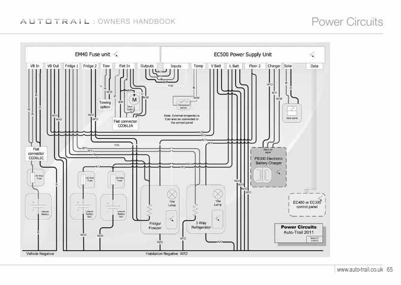
65www.auto-trail.co.uk
Power Circuits: OWNERS HANDBOOK
4187 AT Frontier Owners Handbook REPRO v2:Layout 1 29/10/10 14:11 Page 64

T A K E Y O U R S O N A N A D V E N T U R E66
Consumer Circuits - Roof
4187 AT Frontier Owners Handbook REPRO v2:Layout 1 29/10/10 14:11 Page 65

67www.auto-trail.co.uk
Consumer Circuits - Floor: OWNERS HANDBOOK
4187 AT Frontier Owners Handbook REPRO v2:Layout 1 29/10/10 14:11 Page 66

T A K E Y O U R S O N A N A D V E N T U R E68
Notes
4187 AT Frontier Owners Handbook REPRO v2:Layout 1 29/10/10 14:11 Page 67

O W N E R ’ S H A N D B O O K : F R O N T I O R
w w w. a u t o - t r a i l . c o . u k
4187
10/
10 D
esig
ned
and
prod
uced
by
Kal-G
roup
T: +
44 (0
)142
7 61
0127
ww
w.ka
l-gro
up.c
o.uk
Auto-Trail VR Limited.Trigano House, Genesis Way, Europarc,Grimsby, North East Lincolnshire, DN37 9TU.Main Reception Tel +44(0) 1472 571000 Fax +44(0) 1472 571001www.auto-trail.co.ukParts Department Tel +44(0) 1472 571003 Fax +44(0) 1472 571002
4187 AT Frontier Cover +5mm spine:Layout 1 19/10/10 13:01 Page 2