Embed Size (px)
Citation preview
The OpenGLR©
Graphics System:A Specification
(Version 2.1 - December 1, 2006)
Mark SegalKurt Akeley
Editor (version 1.1): Chris FrazierEditor (versions 1.2-2.1): Jon Leech
Editor (version 2.0): Pat Brown
Copyright c© 1992-2006 Silicon Graphics, Inc.
This document contains unpublished information ofSilicon Graphics, Inc.
This document is protected by copyright, and contains information proprietary toSilicon Graphics, Inc. Any copying, adaptation, distribution, public performance,or public display of this document without the express written consent of SiliconGraphics, Inc. is strictly prohibited. The receipt or possession of this documentdoes not convey any rights to reproduce, disclose, or distribute its contents, or tomanufacture, use, or sell anything that it may describe, in whole or in part.
U.S. Government Restricted Rights Legend
Use, duplication, or disclosure by the Government is subject to restrictions set forthin FAR 52.227.19(c)(2) or subparagraph (c)(1)(ii) of the Rights in Technical Dataand Computer Software clause at DFARS 252.227-7013 and/or in similar or succes-sor clauses in the FAR or the DOD or NASA FAR Supplement. Unpublished rightsreserved under the copyright laws of the United States. Contractor/manufacturer isSilicon Graphics, Inc., 1600 Amphitheatre Parkway, Mountain View, CA 94043.
OpenGL is a registered trademark of Silicon Graphics, Inc.Unix is a registered trademark of The Open Group.
The ”X” device and X Windows System are trademarks ofThe Open Group.
Contents
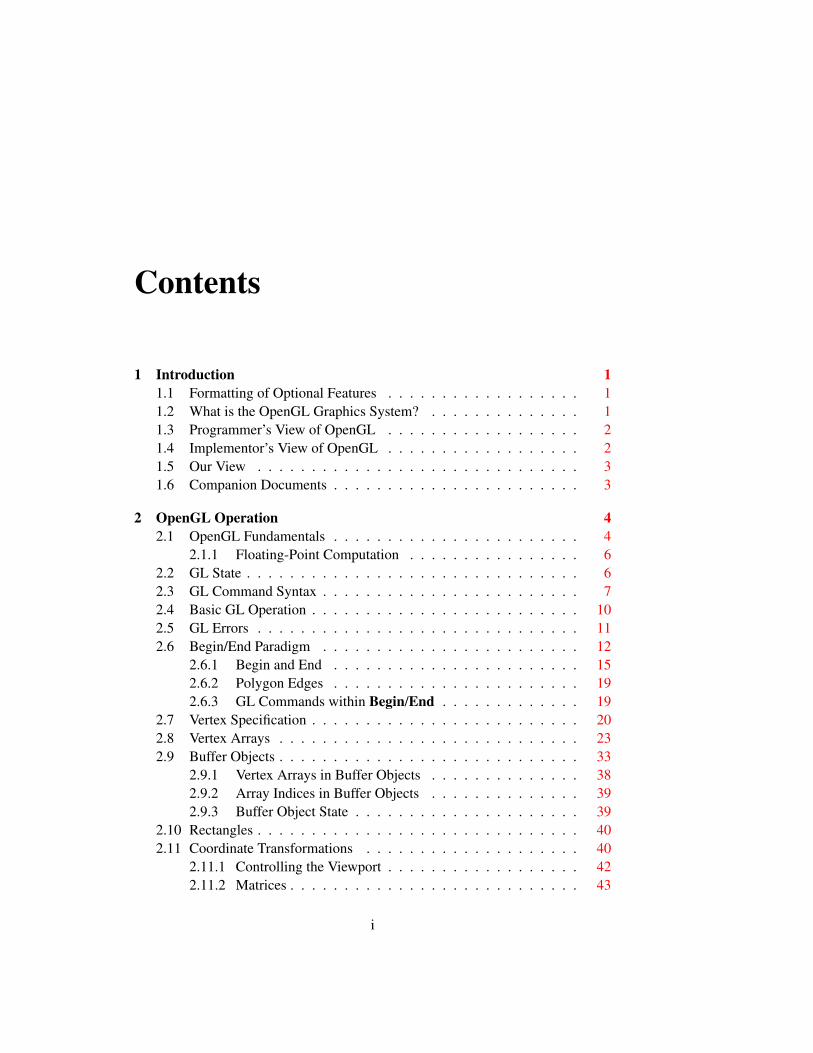
1 Introduction 11.1 Formatting of Optional Features . . . . . . . . . . . . . . . . . . 11.2 What is the OpenGL Graphics System? . . . . . . . . . . . . . . 11.3 Programmer’s View of OpenGL . . . . . . . . . . . . . . . . . . 21.4 Implementor’s View of OpenGL . . . . . . . . . . . . . . . . . . 21.5 Our View . . . . . . . . . . . . . . . . . . . . . . . . . . . . . . 31.6 Companion Documents . . . . . . . . . . . . . . . . . . . . . . . 3
2 OpenGL Operation 42.1 OpenGL Fundamentals . . . . . . . . . . . . . . . . . . . . . . . 4
2.1.1 Floating-Point Computation . . . . . . . . . . . . . . . . 62.2 GL State . . . . . . . . . . . . . . . . . . . . . . . . . . . . . . . 62.3 GL Command Syntax . . . . . . . . . . . . . . . . . . . . . . . . 72.4 Basic GL Operation . . . . . . . . . . . . . . . . . . . . . . . . . 102.5 GL Errors . . . . . . . . . . . . . . . . . . . . . . . . . . . . . . 112.6 Begin/End Paradigm . . . . . . . . . . . . . . . . . . . . . . . . 12
2.6.1 Begin and End . . . . . . . . . . . . . . . . . . . . . . . 152.6.2 Polygon Edges . . . . . . . . . . . . . . . . . . . . . . . 192.6.3 GL Commands within Begin/End . . . . . . . . . . . . . 19
2.7 Vertex Specification . . . . . . . . . . . . . . . . . . . . . . . . . 202.8 Vertex Arrays . . . . . . . . . . . . . . . . . . . . . . . . . . . . 232.9 Buffer Objects . . . . . . . . . . . . . . . . . . . . . . . . . . . . 33
2.9.1 Vertex Arrays in Buffer Objects . . . . . . . . . . . . . . 382.9.2 Array Indices in Buffer Objects . . . . . . . . . . . . . . 392.9.3 Buffer Object State . . . . . . . . . . . . . . . . . . . . . 39
2.10 Rectangles . . . . . . . . . . . . . . . . . . . . . . . . . . . . . . 402.11 Coordinate Transformations . . . . . . . . . . . . . . . . . . . . 40
2.11.1 Controlling the Viewport . . . . . . . . . . . . . . . . . . 422.11.2 Matrices . . . . . . . . . . . . . . . . . . . . . . . . . . . 43
i
ii CONTENTS
2.11.3 Normal Transformation . . . . . . . . . . . . . . . . . . . 482.11.4 Generating Texture Coordinates . . . . . . . . . . . . . . 50
2.12 Clipping . . . . . . . . . . . . . . . . . . . . . . . . . . . . . . . 522.13 Current Raster Position . . . . . . . . . . . . . . . . . . . . . . . 542.14 Colors and Coloring . . . . . . . . . . . . . . . . . . . . . . . . . 57
2.14.1 Lighting . . . . . . . . . . . . . . . . . . . . . . . . . . . 592.14.2 Lighting Parameter Specification . . . . . . . . . . . . . . 642.14.3 ColorMaterial . . . . . . . . . . . . . . . . . . . . . . . 662.14.4 Lighting State . . . . . . . . . . . . . . . . . . . . . . . . 682.14.5 Color Index Lighting . . . . . . . . . . . . . . . . . . . . 682.14.6 Clamping or Masking . . . . . . . . . . . . . . . . . . . 692.14.7 Flatshading . . . . . . . . . . . . . . . . . . . . . . . . . 692.14.8 Color and Associated Data Clipping . . . . . . . . . . . . 702.14.9 Final Color Processing . . . . . . . . . . . . . . . . . . . 71
2.15 Vertex Shaders . . . . . . . . . . . . . . . . . . . . . . . . . . . 712.15.1 Shader Objects . . . . . . . . . . . . . . . . . . . . . . . 722.15.2 Program Objects . . . . . . . . . . . . . . . . . . . . . . 732.15.3 Shader Variables . . . . . . . . . . . . . . . . . . . . . . 752.15.4 Shader Execution . . . . . . . . . . . . . . . . . . . . . . 842.15.5 Required State . . . . . . . . . . . . . . . . . . . . . . . 88
3 Rasterization 903.1 Invariance . . . . . . . . . . . . . . . . . . . . . . . . . . . . . . 923.2 Antialiasing . . . . . . . . . . . . . . . . . . . . . . . . . . . . . 92
3.2.1 Multisampling . . . . . . . . . . . . . . . . . . . . . . . 933.3 Points . . . . . . . . . . . . . . . . . . . . . . . . . . . . . . . . 95
3.3.1 Basic Point Rasterization . . . . . . . . . . . . . . . . . . 973.3.2 Point Rasterization State . . . . . . . . . . . . . . . . . . 1013.3.3 Point Multisample Rasterization . . . . . . . . . . . . . . 101
3.4 Line Segments . . . . . . . . . . . . . . . . . . . . . . . . . . . 1013.4.1 Basic Line Segment Rasterization . . . . . . . . . . . . . 1023.4.2 Other Line Segment Features . . . . . . . . . . . . . . . . 1043.4.3 Line Rasterization State . . . . . . . . . . . . . . . . . . 1073.4.4 Line Multisample Rasterization . . . . . . . . . . . . . . 107
3.5 Polygons . . . . . . . . . . . . . . . . . . . . . . . . . . . . . . 1083.5.1 Basic Polygon Rasterization . . . . . . . . . . . . . . . . 1083.5.2 Stippling . . . . . . . . . . . . . . . . . . . . . . . . . . 1103.5.3 Antialiasing . . . . . . . . . . . . . . . . . . . . . . . . . 1113.5.4 Options Controlling Polygon Rasterization . . . . . . . . 1113.5.5 Depth Offset . . . . . . . . . . . . . . . . . . . . . . . . 111
Version 2.1 - December 1, 2006
CONTENTS iii
3.5.6 Polygon Multisample Rasterization . . . . . . . . . . . . 1133.5.7 Polygon Rasterization State . . . . . . . . . . . . . . . . 113
3.6 Pixel Rectangles . . . . . . . . . . . . . . . . . . . . . . . . . . . 1133.6.1 Pixel Storage Modes and Pixel Buffer Objects . . . . . . . 1143.6.2 The Imaging Subset . . . . . . . . . . . . . . . . . . . . 1153.6.3 Pixel Transfer Modes . . . . . . . . . . . . . . . . . . . . 1163.6.4 Rasterization of Pixel Rectangles . . . . . . . . . . . . . 1273.6.5 Pixel Transfer Operations . . . . . . . . . . . . . . . . . 1383.6.6 Pixel Rectangle Multisample Rasterization . . . . . . . . 148
3.7 Bitmaps . . . . . . . . . . . . . . . . . . . . . . . . . . . . . . . 1483.8 Texturing . . . . . . . . . . . . . . . . . . . . . . . . . . . . . . 150
3.8.1 Texture Image Specification . . . . . . . . . . . . . . . . 1513.8.2 Alternate Texture Image Specification Commands . . . . 1593.8.3 Compressed Texture Images . . . . . . . . . . . . . . . . 1653.8.4 Texture Parameters . . . . . . . . . . . . . . . . . . . . . 1683.8.5 Depth Component Textures . . . . . . . . . . . . . . . . 1703.8.6 Cube Map Texture Selection . . . . . . . . . . . . . . . . 1703.8.7 Texture Wrap Modes . . . . . . . . . . . . . . . . . . . . 1713.8.8 Texture Minification . . . . . . . . . . . . . . . . . . . . 1723.8.9 Texture Magnification . . . . . . . . . . . . . . . . . . . 1783.8.10 Texture Completeness . . . . . . . . . . . . . . . . . . . 1793.8.11 Texture State and Proxy State . . . . . . . . . . . . . . . 1803.8.12 Texture Objects . . . . . . . . . . . . . . . . . . . . . . . 1823.8.13 Texture Environments and Texture Functions . . . . . . . 1843.8.14 Texture Comparison Modes . . . . . . . . . . . . . . . . 1873.8.15 sRGB Texture Color Conversion . . . . . . . . . . . . . . 1913.8.16 Texture Application . . . . . . . . . . . . . . . . . . . . . 191
3.9 Color Sum . . . . . . . . . . . . . . . . . . . . . . . . . . . . . . 1943.10 Fog . . . . . . . . . . . . . . . . . . . . . . . . . . . . . . . . . 1943.11 Fragment Shaders . . . . . . . . . . . . . . . . . . . . . . . . . . 196
3.11.1 Shader Variables . . . . . . . . . . . . . . . . . . . . . . 1963.11.2 Shader Execution . . . . . . . . . . . . . . . . . . . . . . 197
3.12 Antialiasing Application . . . . . . . . . . . . . . . . . . . . . . 1993.13 Multisample Point Fade . . . . . . . . . . . . . . . . . . . . . . . 200
4 Per-Fragment Operations and the Framebuffer 2014.1 Per-Fragment Operations . . . . . . . . . . . . . . . . . . . . . . 202
4.1.1 Pixel Ownership Test . . . . . . . . . . . . . . . . . . . . 2024.1.2 Scissor Test . . . . . . . . . . . . . . . . . . . . . . . . . 2034.1.3 Multisample Fragment Operations . . . . . . . . . . . . . 203
Version 2.1 - December 1, 2006
iv CONTENTS
4.1.4 Alpha Test . . . . . . . . . . . . . . . . . . . . . . . . . 2044.1.5 Stencil Test . . . . . . . . . . . . . . . . . . . . . . . . . 2054.1.6 Depth Buffer Test . . . . . . . . . . . . . . . . . . . . . . 2064.1.7 Occlusion Queries . . . . . . . . . . . . . . . . . . . . . 2074.1.8 Blending . . . . . . . . . . . . . . . . . . . . . . . . . . 2094.1.9 Dithering . . . . . . . . . . . . . . . . . . . . . . . . . . 2124.1.10 Logical Operation . . . . . . . . . . . . . . . . . . . . . 2134.1.11 Additional Multisample Fragment Operations . . . . . . . 213
4.2 Whole Framebuffer Operations . . . . . . . . . . . . . . . . . . . 2154.2.1 Selecting a Buffer for Writing . . . . . . . . . . . . . . . 2154.2.2 Fine Control of Buffer Updates . . . . . . . . . . . . . . 2174.2.3 Clearing the Buffers . . . . . . . . . . . . . . . . . . . . 2184.2.4 The Accumulation Buffer . . . . . . . . . . . . . . . . . 220
4.3 Drawing, Reading, and Copying Pixels . . . . . . . . . . . . . . . 2214.3.1 Writing to the Stencil Buffer . . . . . . . . . . . . . . . . 2214.3.2 Reading Pixels . . . . . . . . . . . . . . . . . . . . . . . 2224.3.3 Copying Pixels . . . . . . . . . . . . . . . . . . . . . . . 2264.3.4 Pixel Draw/Read State . . . . . . . . . . . . . . . . . . . 229
5 Special Functions 2305.1 Evaluators . . . . . . . . . . . . . . . . . . . . . . . . . . . . . . 2305.2 Selection . . . . . . . . . . . . . . . . . . . . . . . . . . . . . . 2365.3 Feedback . . . . . . . . . . . . . . . . . . . . . . . . . . . . . . 2385.4 Display Lists . . . . . . . . . . . . . . . . . . . . . . . . . . . . 2405.5 Flush and Finish . . . . . . . . . . . . . . . . . . . . . . . . . . . 2455.6 Hints . . . . . . . . . . . . . . . . . . . . . . . . . . . . . . . . . 245
6 State and State Requests 2476.1 Querying GL State . . . . . . . . . . . . . . . . . . . . . . . . . 247
6.1.1 Simple Queries . . . . . . . . . . . . . . . . . . . . . . . 2476.1.2 Data Conversions . . . . . . . . . . . . . . . . . . . . . . 2486.1.3 Enumerated Queries . . . . . . . . . . . . . . . . . . . . 2496.1.4 Texture Queries . . . . . . . . . . . . . . . . . . . . . . . 2516.1.5 Stipple Query . . . . . . . . . . . . . . . . . . . . . . . . 2536.1.6 Color Matrix Query . . . . . . . . . . . . . . . . . . . . . 2536.1.7 Color Table Query . . . . . . . . . . . . . . . . . . . . . 2546.1.8 Convolution Query . . . . . . . . . . . . . . . . . . . . . 2546.1.9 Histogram Query . . . . . . . . . . . . . . . . . . . . . . 2556.1.10 Minmax Query . . . . . . . . . . . . . . . . . . . . . . . 2566.1.11 Pointer and String Queries . . . . . . . . . . . . . . . . . 257
Version 2.1 - December 1, 2006
CONTENTS v
6.1.12 Occlusion Queries . . . . . . . . . . . . . . . . . . . . . 2586.1.13 Buffer Object Queries . . . . . . . . . . . . . . . . . . . 2596.1.14 Shader and Program Queries . . . . . . . . . . . . . . . . 2606.1.15 Saving and Restoring State . . . . . . . . . . . . . . . . . 264
6.2 State Tables . . . . . . . . . . . . . . . . . . . . . . . . . . . . . 266
A Invariance 304A.1 Repeatability . . . . . . . . . . . . . . . . . . . . . . . . . . . . 304A.2 Multi-pass Algorithms . . . . . . . . . . . . . . . . . . . . . . . 305A.3 Invariance Rules . . . . . . . . . . . . . . . . . . . . . . . . . . . 305A.4 What All This Means . . . . . . . . . . . . . . . . . . . . . . . . 307
B Corollaries 308
C Version 1.1 311C.1 Vertex Array . . . . . . . . . . . . . . . . . . . . . . . . . . . . . 311C.2 Polygon Offset . . . . . . . . . . . . . . . . . . . . . . . . . . . 312C.3 Logical Operation . . . . . . . . . . . . . . . . . . . . . . . . . . 312C.4 Texture Image Formats . . . . . . . . . . . . . . . . . . . . . . . 312C.5 Texture Replace Environment . . . . . . . . . . . . . . . . . . . . 312C.6 Texture Proxies . . . . . . . . . . . . . . . . . . . . . . . . . . . 313C.7 Copy Texture and Subtexture . . . . . . . . . . . . . . . . . . . . 313C.8 Texture Objects . . . . . . . . . . . . . . . . . . . . . . . . . . . 313C.9 Other Changes . . . . . . . . . . . . . . . . . . . . . . . . . . . 313C.10 Acknowledgements . . . . . . . . . . . . . . . . . . . . . . . . . 314
D Version 1.2 316D.1 Three-Dimensional Texturing . . . . . . . . . . . . . . . . . . . . 316D.2 BGRA Pixel Formats . . . . . . . . . . . . . . . . . . . . . . . . 316D.3 Packed Pixel Formats . . . . . . . . . . . . . . . . . . . . . . . . 317D.4 Normal Rescaling . . . . . . . . . . . . . . . . . . . . . . . . . . 317D.5 Separate Specular Color . . . . . . . . . . . . . . . . . . . . . . 317D.6 Texture Coordinate Edge Clamping . . . . . . . . . . . . . . . . 317D.7 Texture Level of Detail Control . . . . . . . . . . . . . . . . . . . 318D.8 Vertex Array Draw Element Range . . . . . . . . . . . . . . . . . 318D.9 Imaging Subset . . . . . . . . . . . . . . . . . . . . . . . . . . . 318
D.9.1 Color Tables . . . . . . . . . . . . . . . . . . . . . . . . 318D.9.2 Convolution . . . . . . . . . . . . . . . . . . . . . . . . . 319D.9.3 Color Matrix . . . . . . . . . . . . . . . . . . . . . . . . 319D.9.4 Pixel Pipeline Statistics . . . . . . . . . . . . . . . . . . . 320
Version 2.1 - December 1, 2006
vi CONTENTS
D.9.5 Constant Blend Color . . . . . . . . . . . . . . . . . . . . 320D.9.6 New Blending Equations . . . . . . . . . . . . . . . . . . 320
D.10 Acknowledgements . . . . . . . . . . . . . . . . . . . . . . . . . 320
E Version 1.2.1 324
F Version 1.3 325F.1 Compressed Textures . . . . . . . . . . . . . . . . . . . . . . . . 325F.2 Cube Map Textures . . . . . . . . . . . . . . . . . . . . . . . . . 325F.3 Multisample . . . . . . . . . . . . . . . . . . . . . . . . . . . . . 326F.4 Multitexture . . . . . . . . . . . . . . . . . . . . . . . . . . . . . 326F.5 Texture Add Environment Mode . . . . . . . . . . . . . . . . . . 327F.6 Texture Combine Environment Mode . . . . . . . . . . . . . . . 327F.7 Texture Dot3 Environment Mode . . . . . . . . . . . . . . . . . . 327F.8 Texture Border Clamp . . . . . . . . . . . . . . . . . . . . . . . 327F.9 Transpose Matrix . . . . . . . . . . . . . . . . . . . . . . . . . . 328F.10 Acknowledgements . . . . . . . . . . . . . . . . . . . . . . . . . 328
G Version 1.4 333G.1 Automatic Mipmap Generation . . . . . . . . . . . . . . . . . . . 333G.2 Blend Squaring . . . . . . . . . . . . . . . . . . . . . . . . . . . 333G.3 Changes to the Imaging Subset . . . . . . . . . . . . . . . . . . . 334G.4 Depth Textures and Shadows . . . . . . . . . . . . . . . . . . . . 334G.5 Fog Coordinate . . . . . . . . . . . . . . . . . . . . . . . . . . . 334G.6 Multiple Draw Arrays . . . . . . . . . . . . . . . . . . . . . . . . 334G.7 Point Parameters . . . . . . . . . . . . . . . . . . . . . . . . . . 335G.8 Secondary Color . . . . . . . . . . . . . . . . . . . . . . . . . . 335G.9 Separate Blend Functions . . . . . . . . . . . . . . . . . . . . . . 335G.10 Stencil Wrap . . . . . . . . . . . . . . . . . . . . . . . . . . . . 335G.11 Texture Crossbar Environment Mode . . . . . . . . . . . . . . . . 335G.12 Texture LOD Bias . . . . . . . . . . . . . . . . . . . . . . . . . . 336G.13 Texture Mirrored Repeat . . . . . . . . . . . . . . . . . . . . . . 336G.14 Window Raster Position . . . . . . . . . . . . . . . . . . . . . . 336G.15 Acknowledgements . . . . . . . . . . . . . . . . . . . . . . . . . 336
H Version 1.5 339H.1 Buffer Objects . . . . . . . . . . . . . . . . . . . . . . . . . . . . 339H.2 Occlusion Queries . . . . . . . . . . . . . . . . . . . . . . . . . . 340H.3 Shadow Functions . . . . . . . . . . . . . . . . . . . . . . . . . . 340H.4 Changed Tokens . . . . . . . . . . . . . . . . . . . . . . . . . . . 340
Version 2.1 - December 1, 2006
CONTENTS vii
H.5 Acknowledgements . . . . . . . . . . . . . . . . . . . . . . . . . 340
I Version 2.0 345I.1 Programmable Shading . . . . . . . . . . . . . . . . . . . . . . . 345
I.1.1 Shader Objects . . . . . . . . . . . . . . . . . . . . . . . 345I.1.2 Shader Programs . . . . . . . . . . . . . . . . . . . . . . 345I.1.3 OpenGL Shading Language . . . . . . . . . . . . . . . . 346I.1.4 Changes To Shader APIs . . . . . . . . . . . . . . . . . . 346
I.2 Multiple Render Targets . . . . . . . . . . . . . . . . . . . . . . 346I.3 Non-Power-Of-Two Textures . . . . . . . . . . . . . . . . . . . . 346I.4 Point Sprites . . . . . . . . . . . . . . . . . . . . . . . . . . . . . 347I.5 Separate Blend Equation . . . . . . . . . . . . . . . . . . . . . . 347I.6 Separate Stencil . . . . . . . . . . . . . . . . . . . . . . . . . . . 347I.7 Other Changes . . . . . . . . . . . . . . . . . . . . . . . . . . . 347I.8 Acknowledgements . . . . . . . . . . . . . . . . . . . . . . . . . 349
J Version 2.1 351J.1 OpenGL Shading Language . . . . . . . . . . . . . . . . . . . . 351J.2 Non-Square Matrices . . . . . . . . . . . . . . . . . . . . . . . . 351J.3 Pixel Buffer Objects . . . . . . . . . . . . . . . . . . . . . . . . . 351J.4 sRGB Textures . . . . . . . . . . . . . . . . . . . . . . . . . . . 352J.5 Other Changes . . . . . . . . . . . . . . . . . . . . . . . . . . . 352J.6 Acknowledgements . . . . . . . . . . . . . . . . . . . . . . . . . 354
K ARB Extensions 356K.1 Naming Conventions . . . . . . . . . . . . . . . . . . . . . . . . 356K.2 Promoting Extensions to Core Features . . . . . . . . . . . . . . 357K.3 Multitexture . . . . . . . . . . . . . . . . . . . . . . . . . . . . . 357K.4 Transpose Matrix . . . . . . . . . . . . . . . . . . . . . . . . . . 357K.5 Multisample . . . . . . . . . . . . . . . . . . . . . . . . . . . . . 357K.6 Texture Add Environment Mode . . . . . . . . . . . . . . . . . . 358K.7 Cube Map Textures . . . . . . . . . . . . . . . . . . . . . . . . . 358K.8 Compressed Textures . . . . . . . . . . . . . . . . . . . . . . . . 358K.9 Texture Border Clamp . . . . . . . . . . . . . . . . . . . . . . . 358K.10 Point Parameters . . . . . . . . . . . . . . . . . . . . . . . . . . 358K.11 Vertex Blend . . . . . . . . . . . . . . . . . . . . . . . . . . . . 358K.12 Matrix Palette . . . . . . . . . . . . . . . . . . . . . . . . . . . . 359K.13 Texture Combine Environment Mode . . . . . . . . . . . . . . . 359K.14 Texture Crossbar Environment Mode . . . . . . . . . . . . . . . . 359K.15 Texture Dot3 Environment Mode . . . . . . . . . . . . . . . . . . 359
Version 2.1 - December 1, 2006
viii CONTENTS
K.16 Texture Mirrored Repeat . . . . . . . . . . . . . . . . . . . . . . 359K.17 Depth Texture . . . . . . . . . . . . . . . . . . . . . . . . . . . . 359K.18 Shadow . . . . . . . . . . . . . . . . . . . . . . . . . . . . . . . 359K.19 Shadow Ambient . . . . . . . . . . . . . . . . . . . . . . . . . . 360K.20 Window Raster Position . . . . . . . . . . . . . . . . . . . . . . 360K.21 Low-Level Vertex Programming . . . . . . . . . . . . . . . . . . 360K.22 Low-Level Fragment Programming . . . . . . . . . . . . . . . . 360K.23 Buffer Objects . . . . . . . . . . . . . . . . . . . . . . . . . . . . 360K.24 Occlusion Queries . . . . . . . . . . . . . . . . . . . . . . . . . . 361K.25 Shader Objects . . . . . . . . . . . . . . . . . . . . . . . . . . . 361K.26 High-Level Vertex Programming . . . . . . . . . . . . . . . . . . 361K.27 High-Level Fragment Programming . . . . . . . . . . . . . . . . 361K.28 OpenGL Shading Language . . . . . . . . . . . . . . . . . . . . 361K.29 Non-Power-Of-Two Textures . . . . . . . . . . . . . . . . . . . . 361K.30 Point Sprites . . . . . . . . . . . . . . . . . . . . . . . . . . . . . 362K.31 Fragment Program Shadow . . . . . . . . . . . . . . . . . . . . . 362K.32 Multiple Render Targets . . . . . . . . . . . . . . . . . . . . . . 362K.33 Rectangular Textures . . . . . . . . . . . . . . . . . . . . . . . . 362K.34 Floating-Point Color Buffers . . . . . . . . . . . . . . . . . . . . 362K.35 Half-Precision Floating Point . . . . . . . . . . . . . . . . . . . . 363K.36 Floating-Point Textures . . . . . . . . . . . . . . . . . . . . . . . 363K.37 Pixel Buffer Objects . . . . . . . . . . . . . . . . . . . . . . . . . 363
Version 2.1 - December 1, 2006
List of Figures
2.1 Block diagram of the GL. . . . . . . . . . . . . . . . . . . . . . . 102.2 Creation of a processed vertex from a transformed vertex and cur-
rent values. . . . . . . . . . . . . . . . . . . . . . . . . . . . . . 132.3 Primitive assembly and processing. . . . . . . . . . . . . . . . . . 132.4 Triangle strips, fans, and independent triangles. . . . . . . . . . . 162.5 Quadrilateral strips and independent quadrilaterals. . . . . . . . . 182.6 Vertex transformation sequence. . . . . . . . . . . . . . . . . . . 412.7 Current raster position. . . . . . . . . . . . . . . . . . . . . . . . 552.8 Processing of RGBA colors. . . . . . . . . . . . . . . . . . . . . 572.9 Processing of color indices. . . . . . . . . . . . . . . . . . . . . . 572.10 ColorMaterial operation. . . . . . . . . . . . . . . . . . . . . . . 66
3.1 Rasterization. . . . . . . . . . . . . . . . . . . . . . . . . . . . . 903.2 Rasterization of non-antialiased wide points. . . . . . . . . . . . . 973.3 Rasterization of antialiased wide points. . . . . . . . . . . . . . . 973.4 Visualization of Bresenham’s algorithm. . . . . . . . . . . . . . . 1023.5 Rasterization of non-antialiased wide lines. . . . . . . . . . . . . 1053.6 The region used in rasterizing an antialiased line segment. . . . . 1063.7 Operation of DrawPixels. . . . . . . . . . . . . . . . . . . . . . 1273.8 Selecting a subimage from an image . . . . . . . . . . . . . . . . 1313.9 A bitmap and its associated parameters. . . . . . . . . . . . . . . 1493.10 A texture image and the coordinates used to access it. . . . . . . . 1593.11 Multitexture pipeline. . . . . . . . . . . . . . . . . . . . . . . . . 192
4.1 Per-fragment operations. . . . . . . . . . . . . . . . . . . . . . . 2024.2 Operation of ReadPixels. . . . . . . . . . . . . . . . . . . . . . . 2224.3 Operation of CopyPixels. . . . . . . . . . . . . . . . . . . . . . . 226
5.1 Map Evaluation. . . . . . . . . . . . . . . . . . . . . . . . . . . . 2325.2 Feedback syntax. . . . . . . . . . . . . . . . . . . . . . . . . . . 241
ix
List of Tables
2.1 GL command suffixes . . . . . . . . . . . . . . . . . . . . . . . . 82.2 GL data types . . . . . . . . . . . . . . . . . . . . . . . . . . . . 92.3 Summary of GL errors . . . . . . . . . . . . . . . . . . . . . . . 122.4 Vertex array sizes (values per vertex) and data types . . . . . . . . 252.5 Variables that direct the execution of InterleavedArrays. . . . . . 322.6 Buffer object parameters and their values. . . . . . . . . . . . . . 342.7 Buffer object initial state. . . . . . . . . . . . . . . . . . . . . . . 362.8 Buffer object state set by MapBuffer. . . . . . . . . . . . . . . . 372.9 Component conversions . . . . . . . . . . . . . . . . . . . . . . . 592.10 Summary of lighting parameters. . . . . . . . . . . . . . . . . . . 612.11 Correspondence of lighting parameter symbols to names. . . . . . 652.12 Polygon flatshading color selection. . . . . . . . . . . . . . . . . 70
3.1 PixelStore parameters. . . . . . . . . . . . . . . . . . . . . . . . 1153.2 PixelTransfer parameters. . . . . . . . . . . . . . . . . . . . . . 1173.3 PixelMap parameters. . . . . . . . . . . . . . . . . . . . . . . . 1183.4 Color table names. . . . . . . . . . . . . . . . . . . . . . . . . . 1193.5 DrawPixels and ReadPixels types. . . . . . . . . . . . . . . . . . 1293.6 DrawPixels and ReadPixels formats. . . . . . . . . . . . . . . . 1303.7 Swap Bytes bit ordering. . . . . . . . . . . . . . . . . . . . . . . 1303.8 Packed pixel formats. . . . . . . . . . . . . . . . . . . . . . . . . 1323.9 UNSIGNED BYTE formats. Bit numbers are indicated for each com-
ponent. . . . . . . . . . . . . . . . . . . . . . . . . . . . . . . . 1333.10 UNSIGNED SHORT formats . . . . . . . . . . . . . . . . . . . . . 1343.11 UNSIGNED INT formats . . . . . . . . . . . . . . . . . . . . . . . 1353.12 Packed pixel field assignments. . . . . . . . . . . . . . . . . . . . 1363.13 Color table lookup. . . . . . . . . . . . . . . . . . . . . . . . . . 1413.14 Computation of filtered color components. . . . . . . . . . . . . . 142
x
LIST OF TABLES xi
3.15 Conversion from RGBA and depth pixel components to internaltexture, table, or filter components. . . . . . . . . . . . . . . . . . 152
3.16 Correspondence of sized internal formats to base internal formats. 1553.17 Generic and specific compressed internal formats. . . . . . . . . . 1553.18 Texture parameters and their values. . . . . . . . . . . . . . . . . 1693.19 Selection of cube map images. . . . . . . . . . . . . . . . . . . . 1703.20 Correspondence of filtered texture components. . . . . . . . . . . 1863.21 Texture functions REPLACE, MODULATE, and DECAL . . . . . . . . 1863.22 Texture functions BLEND and ADD. . . . . . . . . . . . . . . . . . 1873.23 COMBINE texture functions. . . . . . . . . . . . . . . . . . . . . . 1883.24 Arguments for COMBINE RGB functions. . . . . . . . . . . . . . . 1893.25 Arguments for COMBINE ALPHA functions. . . . . . . . . . . . . 1893.26 Depth texture comparison functions. . . . . . . . . . . . . . . . . 190
4.1 RGB and Alpha blend equations. . . . . . . . . . . . . . . . . . . 2104.2 Blending functions. . . . . . . . . . . . . . . . . . . . . . . . . . 2114.3 Arguments to LogicOp and their corresponding operations. . . . . 2144.4 Arguments to DrawBuffer and the buffers that they indicate. . . . 2164.5 PixelStore parameters. . . . . . . . . . . . . . . . . . . . . . . . 2244.6 ReadPixels index masks. . . . . . . . . . . . . . . . . . . . . . . 2264.7 ReadPixels GL data types and reversed component conversion for-
mulas. . . . . . . . . . . . . . . . . . . . . . . . . . . . . . . . . 227
5.1 Values specified by the target to Map1. . . . . . . . . . . . . . . 2315.2 Correspondence of feedback type to number of values per vertex. . 2405.3 Hint targets and descriptions . . . . . . . . . . . . . . . . . . . . 246
6.1 Texture, table, and filter return values. . . . . . . . . . . . . . . . 2536.2 Attribute groups . . . . . . . . . . . . . . . . . . . . . . . . . . . 2656.3 State Variable Types . . . . . . . . . . . . . . . . . . . . . . . . . 2676.4 GL Internal begin-end state variables (inaccessible) . . . . . . . . 2696.5 Current Values and Associated Data . . . . . . . . . . . . . . . . 2706.6 Vertex Array Data . . . . . . . . . . . . . . . . . . . . . . . . . . 2716.7 Vertex Array Data (cont.) . . . . . . . . . . . . . . . . . . . . . . 2726.8 Vertex Array Data (cont.) . . . . . . . . . . . . . . . . . . . . . . 2736.9 Buffer Object State . . . . . . . . . . . . . . . . . . . . . . . . . 2746.10 Transformation state . . . . . . . . . . . . . . . . . . . . . . . . 2756.11 Coloring . . . . . . . . . . . . . . . . . . . . . . . . . . . . . . . 2766.12 Lighting (see also table 2.10 for defaults) . . . . . . . . . . . . . 2776.13 Lighting (cont.) . . . . . . . . . . . . . . . . . . . . . . . . . . . 278
Version 2.1 - December 1, 2006
xii LIST OF TABLES
6.14 Rasterization . . . . . . . . . . . . . . . . . . . . . . . . . . . . 2796.15 Multisampling . . . . . . . . . . . . . . . . . . . . . . . . . . . . 2806.16 Textures (state per texture unit and binding point) . . . . . . . . . 2816.17 Textures (state per texture object) . . . . . . . . . . . . . . . . . . 2826.18 Textures (state per texture image) . . . . . . . . . . . . . . . . . . 2836.19 Texture Environment and Generation . . . . . . . . . . . . . . . . 2846.20 Pixel Operations . . . . . . . . . . . . . . . . . . . . . . . . . . . 2856.21 Pixel Operations (cont.) . . . . . . . . . . . . . . . . . . . . . . . 2866.22 Framebuffer Control . . . . . . . . . . . . . . . . . . . . . . . . 2876.23 Pixels . . . . . . . . . . . . . . . . . . . . . . . . . . . . . . . . 2886.24 Pixels (cont.) . . . . . . . . . . . . . . . . . . . . . . . . . . . . 2896.25 Pixels (cont.) . . . . . . . . . . . . . . . . . . . . . . . . . . . . 2906.26 Pixels (cont.) . . . . . . . . . . . . . . . . . . . . . . . . . . . . 2916.27 Pixels (cont.) . . . . . . . . . . . . . . . . . . . . . . . . . . . . 2926.28 Evaluators (GetMap takes a map name) . . . . . . . . . . . . . . 2936.29 Shader Object State . . . . . . . . . . . . . . . . . . . . . . . . . 2946.30 Program Object State . . . . . . . . . . . . . . . . . . . . . . . . 2956.31 Vertex Shader State . . . . . . . . . . . . . . . . . . . . . . . . . 2966.32 Hints . . . . . . . . . . . . . . . . . . . . . . . . . . . . . . . . . 2976.33 Implementation Dependent Values . . . . . . . . . . . . . . . . . 2986.34 Implementation Dependent Values (cont.) . . . . . . . . . . . . . 2996.35 Implementation Dependent Values (cont.) . . . . . . . . . . . . . 3006.36 Implementation Dependent Values (cont.) . . . . . . . . . . . . . 3016.37 Implementation Dependent Pixel Depths . . . . . . . . . . . . . . 3026.38 Miscellaneous . . . . . . . . . . . . . . . . . . . . . . . . . . . . 303
H.1 New token names . . . . . . . . . . . . . . . . . . . . . . . . . . 341
Version 2.1 - December 1, 2006

Chapter 1
Introduction
This document describes the OpenGL graphics system: what it is, how it acts, andwhat is required to implement it. We assume that the reader has at least a rudi-mentary understanding of computer graphics. This means familiarity with the es-sentials of computer graphics algorithms as well as familiarity with basic graphicshardware and associated terms.
1.1 Formatting of Optional Features
Starting with version 1.2 of OpenGL, some features in the specification are consid-ered optional; an OpenGL implementation may or may not choose to provide them(see section 3.6.2).
Portions of the specification which are optional are so described where theoptional features are first defined (see section 3.6.2). State table entries which areoptional are typeset against a gray background .
1.2 What is the OpenGL Graphics System?
OpenGL (for “Open Graphics Library”) is a software interface to graphics hard-ware. The interface consists of a set of several hundred procedures and functionsthat allow a programmer to specify the objects and operations involved in produc-ing high-quality graphical images, specifically color images of three-dimensionalobjects.
Most of OpenGL requires that the graphics hardware contain a framebuffer.Many OpenGL calls pertain to drawing objects such as points, lines, polygons, andbitmaps, but the way that some of this drawing occurs (such as when antialiasing
1
2 CHAPTER 1. INTRODUCTION
or texturing is enabled) relies on the existence of a framebuffer. Further, some ofOpenGL is specifically concerned with framebuffer manipulation.
1.3 Programmer’s View of OpenGL
To the programmer, OpenGL is a set of commands that allow the specification ofgeometric objects in two or three dimensions, together with commands that controlhow these objects are rendered into the framebuffer. For the most part, OpenGLprovides an immediate-mode interface, meaning that specifying an object causes itto be drawn.
A typical program that uses OpenGL begins with calls to open a window intothe framebuffer into which the program will draw. Then, calls are made to allocatea GL context and associate it with the window. Once a GL context is allocated,the programmer is free to issue OpenGL commands. Some calls are used to drawsimple geometric objects (i.e. points, line segments, and polygons), while othersaffect the rendering of these primitives including how they are lit or colored andhow they are mapped from the user’s two- or three-dimensional model space tothe two-dimensional screen. There are also calls to effect direct control of theframebuffer, such as reading and writing pixels.
1.4 Implementor’s View of OpenGL
To the implementor, OpenGL is a set of commands that affect the operation ofgraphics hardware. If the hardware consists only of an addressable framebuffer,then OpenGL must be implemented almost entirely on the host CPU. More typi-cally, the graphics hardware may comprise varying degrees of graphics accelera-tion, from a raster subsystem capable of rendering two-dimensional lines and poly-gons to sophisticated floating-point processors capable of transforming and com-puting on geometric data. The OpenGL implementor’s task is to provide the CPUsoftware interface while dividing the work for each OpenGL command betweenthe CPU and the graphics hardware. This division must be tailored to the availablegraphics hardware to obtain optimum performance in carrying out OpenGL calls.
OpenGL maintains a considerable amount of state information. This state con-trols how objects are drawn into the framebuffer. Some of this state is directlyavailable to the user: he or she can make calls to obtain its value. Some of it, how-ever, is visible only by the effect it has on what is drawn. One of the main goals ofthis specification is to make OpenGL state information explicit, to elucidate how itchanges, and to indicate what its effects are.
Version 2.1 - December 1, 2006
1.5. OUR VIEW 3
1.5 Our View
We view OpenGL as a state machine that controls a set of specific drawing oper-ations. This model should engender a specification that satisfies the needs of bothprogrammers and implementors. It does not, however, necessarily provide a modelfor implementation. An implementation must produce results conforming to thoseproduced by the specified methods, but there may be ways to carry out a particularcomputation that are more efficient than the one specified.
1.6 Companion Documents
This specification should be read together with a companion document titled TheOpenGL Shading Language. The latter document (referred to as the OpenGL Shad-ing Language Specification hereafter) defines the syntax and semantics of the pro-gramming language used to write vertex and fragment shaders (see sections 2.15and 3.11). These sections may include references to concepts and terms (such asshading language variable types) defined in the companion document.
OpenGL 2.0 implementations are guaranteed to support at least version 1.10 ofthe shading language; the actual version supported may be queried as described insection 6.1.11.
Version 2.1 - December 1, 2006
Chapter 2
OpenGL Operation
2.1 OpenGL Fundamentals
OpenGL (henceforth, the “GL”) is concerned only with rendering into a frame-buffer (and reading values stored in that framebuffer). There is no support forother peripherals sometimes associated with graphics hardware, such as mice andkeyboards. Programmers must rely on other mechanisms to obtain user input.
The GL draws primitives subject to a number of selectable modes. Each prim-itive is a point, line segment, polygon, or pixel rectangle. Each mode may bechanged independently; the setting of one does not affect the settings of others(although many modes may interact to determine what eventually ends up in theframebuffer). Modes are set, primitives specified, and other GL operations de-scribed by sending commands in the form of function or procedure calls.
Primitives are defined by a group of one or more vertices. A vertex defines apoint, an endpoint of an edge, or a corner of a polygon where two edges meet. Data(consisting of positional coordinates, colors, normals, and texture coordinates) areassociated with a vertex and each vertex is processed independently, in order, andin the same way. The only exception to this rule is if the group of vertices mustbe clipped so that the indicated primitive fits within a specified region; in thiscase vertex data may be modified and new vertices created. The type of clippingdepends on which primitive the group of vertices represents.
Commands are always processed in the order in which they are received, al-though there may be an indeterminate delay before the effects of a command arerealized. This means, for example, that one primitive must be drawn completelybefore any subsequent one can affect the framebuffer. It also means that queriesand pixel read operations return state consistent with complete execution of allpreviously invoked GL commands, except where explicitly specified otherwise. In
4
2.1. OPENGL FUNDAMENTALS 5
general, the effects of a GL command on either GL modes or the framebuffer mustbe complete before any subsequent command can have any such effects.
In the GL, data binding occurs on call. This means that data passed to a com-mand are interpreted when that command is received. Even if the command re-quires a pointer to data, those data are interpreted when the call is made, and anysubsequent changes to the data have no effect on the GL (unless the same pointeris used in a subsequent command).
The GL provides direct control over the fundamental operations of 3D and 2Dgraphics. This includes specification of such parameters as transformation matri-ces, lighting equation coefficients, antialiasing methods, and pixel update opera-tors. It does not provide a means for describing or modeling complex geometricobjects. Another way to describe this situation is to say that the GL provides mech-anisms to describe how complex geometric objects are to be rendered rather thanmechanisms to describe the complex objects themselves.
The model for interpretation of GL commands is client-server. That is, a pro-gram (the client) issues commands, and these commands are interpreted and pro-cessed by the GL (the server). The server may or may not operate on the samecomputer as the client. In this sense, the GL is “network-transparent.” A servermay maintain a number of GL contexts, each of which is an encapsulation of cur-rent GL state. A client may choose to connect to any one of these contexts. IssuingGL commands when the program is not connected to a context results in undefinedbehavior.
The effects of GL commands on the framebuffer are ultimately controlled bythe window system that allocates framebuffer resources. It is the window sys-tem that determines which portions of the framebuffer the GL may access at anygiven time and that communicates to the GL how those portions are structured.Therefore, there are no GL commands to configure the framebuffer or initialize theGL. Similarly, display of framebuffer contents on a CRT monitor (including thetransformation of individual framebuffer values by such techniques as gamma cor-rection) is not addressed by the GL. Framebuffer configuration occurs outside ofthe GL in conjunction with the window system; the initialization of a GL contextoccurs when the window system allocates a window for GL rendering.
The GL is designed to be run on a range of graphics platforms with varyinggraphics capabilities and performance. To accommodate this variety, we specifyideal behavior instead of actual behavior for certain GL operations. In cases wheredeviation from the ideal is allowed, we also specify the rules that an implemen-tation must obey if it is to approximate the ideal behavior usefully. This allowedvariation in GL behavior implies that two distinct GL implementations may notagree pixel for pixel when presented with the same input even when run on identi-cal framebuffer configurations.
Version 2.1 - December 1, 2006
6 CHAPTER 2. OPENGL OPERATION
Finally, command names, constants, and types are prefixed in the GL (by gl,GL , and GL, respectively in C) to reduce name clashes with other packages. Theprefixes are omitted in this document for clarity.
2.1.1 Floating-Point Computation
The GL must perform a number of floating-point operations during the course ofits operation. We do not specify how floating-point numbers are to be representedor how operations on them are to be performed. We require simply that numbers’floating-point parts contain enough bits and that their exponent fields are largeenough so that individual results of floating-point operations are accurate to about1 part in 105. The maximum representable magnitude of a floating-point numberused to represent positional, normal, or texture coordinates must be at least 232; themaximum representable magnitude for colors must be at least 210. The maximumrepresentable magnitude for all other floating-point values must be at least 232.x · 0 = 0 · x = 0 for any non-infinite and non-NaN x. 1 · x = x · 1 = x.x + 0 = 0 + x = x. 00 = 1. (Occasionally further requirements will be specified.)Most single-precision floating-point formats meet these requirements.
Any representable floating-point value is legal as input to a GL command thatrequires floating-point data. The result of providing a value that is not a floating-point number to such a command is unspecified, but must not lead to GL interrup-tion or termination. In IEEE arithmetic, for example, providing a negative zero or adenormalized number to a GL command yields predictable results, while providinga NaN or an infinity yields unspecified results.
Some calculations require division. In such cases (including implied divisionsrequired by vector normalizations), a division by zero produces an unspecified re-sult but must not lead to GL interruption or termination.
2.2 GL State
The GL maintains considerable state. This document enumerates each state vari-able and describes how each variable can be changed. For purposes of discussion,state variables are categorized somewhat arbitrarily by their function. Although wedescribe the operations that the GL performs on the framebuffer, the framebufferis not a part of GL state.
We distinguish two types of state. The first type of state, called GL serverstate, resides in the GL server. The majority of GL state falls into this category.The second type of state, called GL client state, resides in the GL client. Unlessotherwise specified, all state referred to in this document is GL server state; GL
Version 2.1 - December 1, 2006
2.3. GL COMMAND SYNTAX 7
client state is specifically identified. Each instance of a GL context implies onecomplete set of GL server state; each connection from a client to a server impliesa set of both GL client state and GL server state.
While an implementation of the GL may be hardware dependent, this discus-sion is independent of the specific hardware on which a GL is implemented. We aretherefore concerned with the state of graphics hardware only when it correspondsprecisely to GL state.
2.3 GL Command Syntax
GL commands are functions or procedures. Various groups of commands performthe same operation but differ in how arguments are supplied to them. To conve-niently accommodate this variation, we adopt a notation for describing commandsand their arguments.
GL commands are formed from a name followed, depending on the particularcommand, by up to 4 characters. The first character indicates the number of valuesof the indicated type that must be presented to the command. The second characteror character pair indicates the specific type of the arguments: 8-bit integer, 16-bitinteger, 32-bit integer, single-precision floating-point, or double-precision floating-point. The final character, if present, is v, indicating that the command takes apointer to an array (a vector) of values rather than a series of individual arguments.Two specific examples come from the Vertex command:
void Vertex3f( float x, float y, float z );
and
void Vertex2sv( short v[2] );
These examples show the ANSI C declarations for these commands. In general,a command declaration has the form1
rtype Name{ε1234}{ε b s i f d ub us ui}{εv}( [args ,] T arg1 , . . . , T argN [, args] );
rtype is the return type of the function. The braces ({}) enclose a series of char-acters (or character pairs) of which one is selected. ε indicates no character. Thearguments enclosed in brackets ([args ,] and [, args]) may or may not be present.
1The declarations shown in this document apply to ANSI C. Languages such as C++ and Adathat allow passing of argument type information admit simpler declarations and fewer entry points.
Version 2.1 - December 1, 2006
8 CHAPTER 2. OPENGL OPERATION
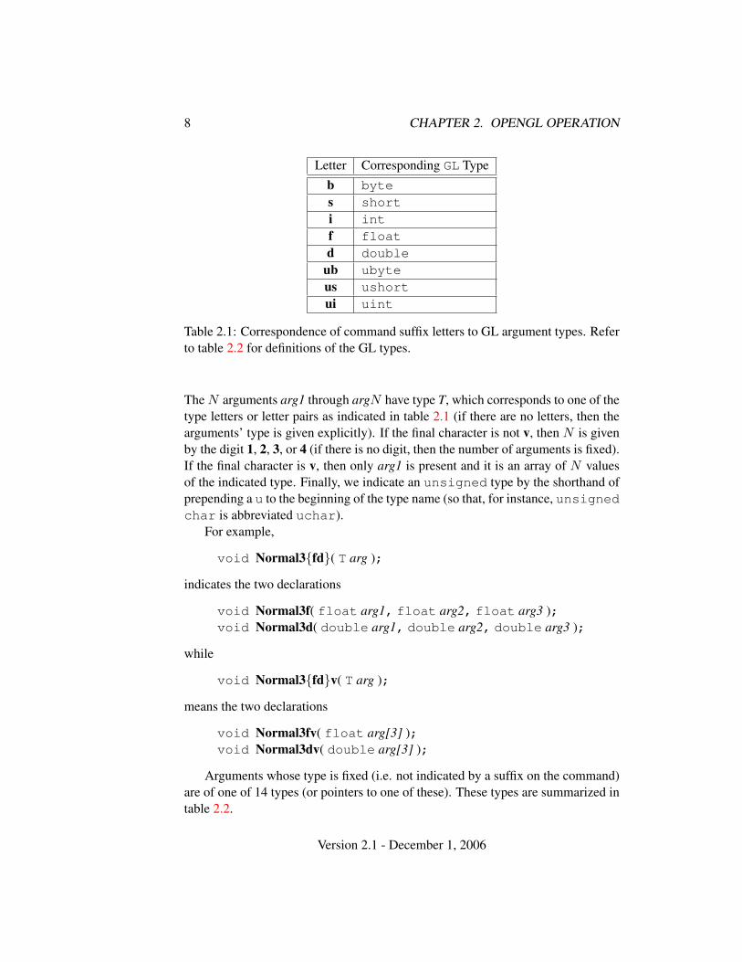
Letter Corresponding GL Typeb bytes shorti intf floatd double
ub ubyteus ushortui uint
Table 2.1: Correspondence of command suffix letters to GL argument types. Referto table 2.2 for definitions of the GL types.
The N arguments arg1 through argN have type T, which corresponds to one of thetype letters or letter pairs as indicated in table 2.1 (if there are no letters, then thearguments’ type is given explicitly). If the final character is not v, then N is givenby the digit 1, 2, 3, or 4 (if there is no digit, then the number of arguments is fixed).If the final character is v, then only arg1 is present and it is an array of N valuesof the indicated type. Finally, we indicate an unsigned type by the shorthand ofprepending a u to the beginning of the type name (so that, for instance, unsignedchar is abbreviated uchar).
For example,
void Normal3{fd}( T arg );
indicates the two declarations
void Normal3f( float arg1, float arg2, float arg3 );void Normal3d( double arg1, double arg2, double arg3 );
while
void Normal3{fd}v( T arg );
means the two declarations
void Normal3fv( float arg[3] );void Normal3dv( double arg[3] );
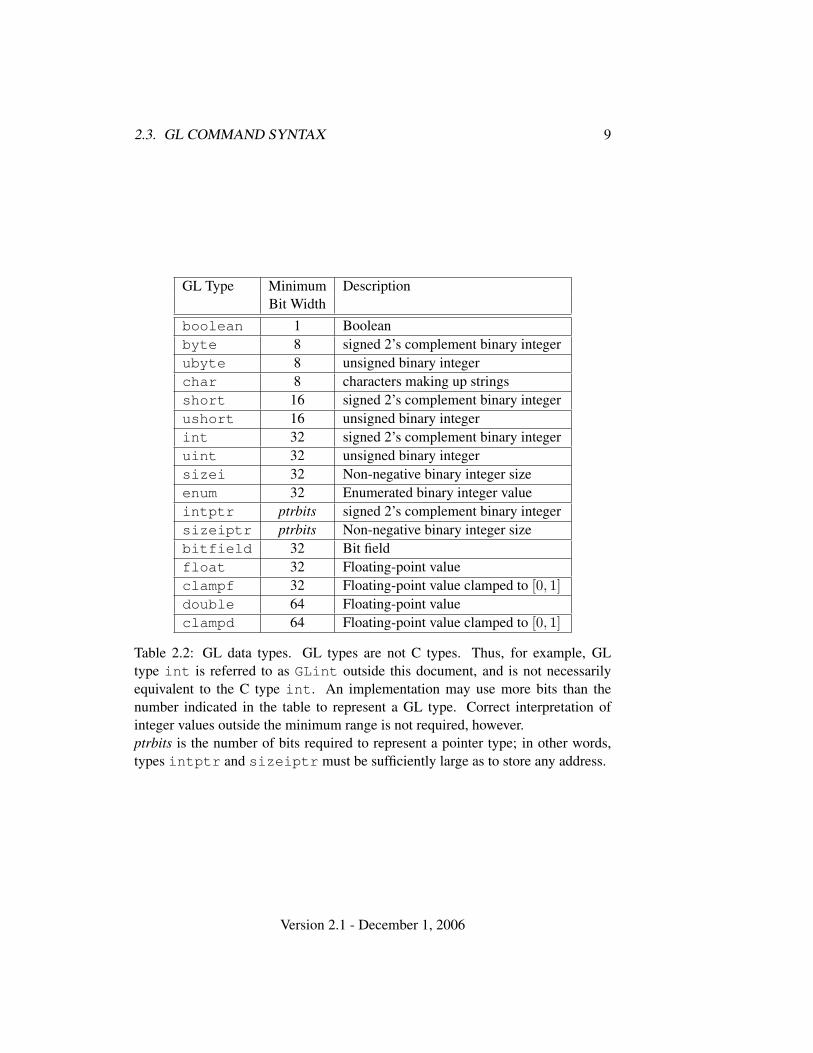
Arguments whose type is fixed (i.e. not indicated by a suffix on the command)are of one of 14 types (or pointers to one of these). These types are summarized intable 2.2.
Version 2.1 - December 1, 2006
2.3. GL COMMAND SYNTAX 9
GL Type Minimum DescriptionBit Width
boolean 1 Booleanbyte 8 signed 2’s complement binary integerubyte 8 unsigned binary integerchar 8 characters making up stringsshort 16 signed 2’s complement binary integerushort 16 unsigned binary integerint 32 signed 2’s complement binary integeruint 32 unsigned binary integersizei 32 Non-negative binary integer sizeenum 32 Enumerated binary integer valueintptr ptrbits signed 2’s complement binary integersizeiptr ptrbits Non-negative binary integer sizebitfield 32 Bit fieldfloat 32 Floating-point valueclampf 32 Floating-point value clamped to [0, 1]double 64 Floating-point valueclampd 64 Floating-point value clamped to [0, 1]
Table 2.2: GL data types. GL types are not C types. Thus, for example, GLtype int is referred to as GLint outside this document, and is not necessarilyequivalent to the C type int. An implementation may use more bits than thenumber indicated in the table to represent a GL type. Correct interpretation ofinteger values outside the minimum range is not required, however.ptrbits is the number of bits required to represent a pointer type; in other words,types intptr and sizeiptr must be sufficiently large as to store any address.
Version 2.1 - December 1, 2006
10 CHAPTER 2. OPENGL OPERATION
Display List
Evaluator
Per−VertexOperations Rasteriz−
ation
Per−FragmentOperations
Framebuffer
PixelOperations
PrimitiveAssembly
TextureMemory
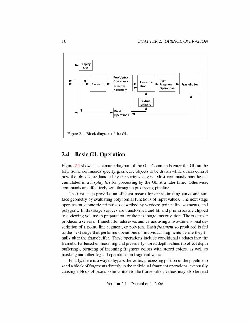
Figure 2.1. Block diagram of the GL.
2.4 Basic GL Operation
Figure 2.1 shows a schematic diagram of the GL. Commands enter the GL on theleft. Some commands specify geometric objects to be drawn while others controlhow the objects are handled by the various stages. Most commands may be ac-cumulated in a display list for processing by the GL at a later time. Otherwise,commands are effectively sent through a processing pipeline.
The first stage provides an efficient means for approximating curve and sur-face geometry by evaluating polynomial functions of input values. The next stageoperates on geometric primitives described by vertices: points, line segments, andpolygons. In this stage vertices are transformed and lit, and primitives are clippedto a viewing volume in preparation for the next stage, rasterization. The rasterizerproduces a series of framebuffer addresses and values using a two-dimensional de-scription of a point, line segment, or polygon. Each fragment so produced is fedto the next stage that performs operations on individual fragments before they fi-nally alter the framebuffer. These operations include conditional updates into theframebuffer based on incoming and previously stored depth values (to effect depthbuffering), blending of incoming fragment colors with stored colors, as well asmasking and other logical operations on fragment values.
Finally, there is a way to bypass the vertex processing portion of the pipeline tosend a block of fragments directly to the individual fragment operations, eventuallycausing a block of pixels to be written to the framebuffer; values may also be read
Version 2.1 - December 1, 2006
2.5. GL ERRORS 11
back from the framebuffer or copied from one portion of the framebuffer to another.These transfers may include some type of decoding or encoding.
This ordering is meant only as a tool for describing the GL, not as a strict ruleof how the GL is implemented, and we present it only as a means to organize thevarious operations of the GL. Objects such as curved surfaces, for instance, maybe transformed before they are converted to polygons.
2.5 GL Errors
The GL detects only a subset of those conditions that could be considered errors.This is because in many cases error checking would adversely impact the perfor-mance of an error-free program.
The command
enum GetError( void );
is used to obtain error information. Each detectable error is assigned a numericcode. When an error is detected, a flag is set and the code is recorded. Furthererrors, if they occur, do not affect this recorded code. When GetError is called,the code is returned and the flag is cleared, so that a further error will again recordits code. If a call to GetError returns NO ERROR, then there has been no detectableerror since the last call to GetError (or since the GL was initialized).
To allow for distributed implementations, there may be several flag-code pairs.In this case, after a call to GetError returns a value other than NO ERROR eachsubsequent call returns the non-zero code of a distinct flag-code pair (in unspecifiedorder), until all non-NO ERROR codes have been returned. When there are no morenon-NO ERROR error codes, all flags are reset. This scheme requires some positivenumber of pairs of a flag bit and an integer. The initial state of all flags is clearedand the initial value of all codes is NO ERROR.
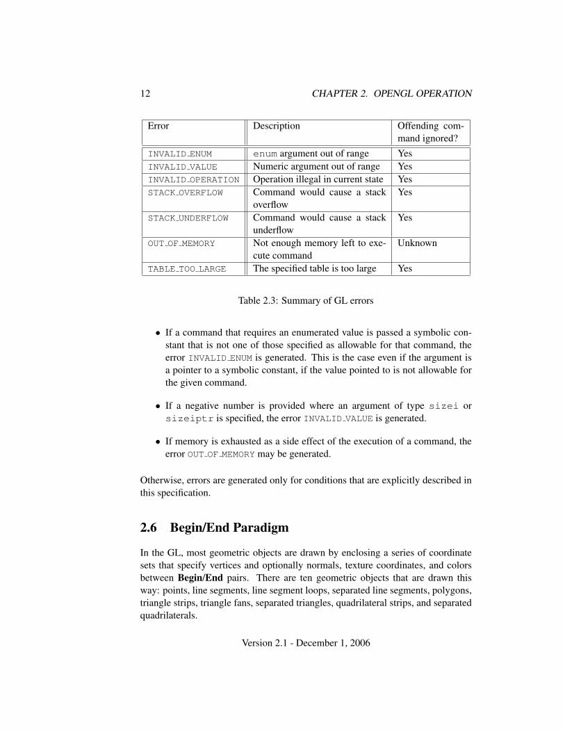
Table 2.3 summarizes GL errors. Currently, when an error flag is set, results ofGL operation are undefined only if OUT OF MEMORY has occurred. In other cases,the command generating the error is ignored so that it has no effect on GL state orframebuffer contents. If the generating command returns a value, it returns zero. Ifthe generating command modifies values through a pointer argument, no change ismade to these values. These error semantics apply only to GL errors, not to systemerrors such as memory access errors. This behavior is the current behavior; theaction of the GL in the presence of errors is subject to change.
Several error generation conditions are implicit in the description of every GLcommand:
Version 2.1 - December 1, 2006
12 CHAPTER 2. OPENGL OPERATION
Error Description Offending com-mand ignored?
INVALID ENUM enum argument out of range YesINVALID VALUE Numeric argument out of range YesINVALID OPERATION Operation illegal in current state YesSTACK OVERFLOW Command would cause a stack
overflowYes
STACK UNDERFLOW Command would cause a stackunderflow
Yes
OUT OF MEMORY Not enough memory left to exe-cute command
Unknown
TABLE TOO LARGE The specified table is too large Yes
Table 2.3: Summary of GL errors
• If a command that requires an enumerated value is passed a symbolic con-stant that is not one of those specified as allowable for that command, theerror INVALID ENUM is generated. This is the case even if the argument isa pointer to a symbolic constant, if the value pointed to is not allowable forthe given command.
• If a negative number is provided where an argument of type sizei orsizeiptr is specified, the error INVALID VALUE is generated.
• If memory is exhausted as a side effect of the execution of a command, theerror OUT OF MEMORY may be generated.
Otherwise, errors are generated only for conditions that are explicitly described inthis specification.
2.6 Begin/End Paradigm
In the GL, most geometric objects are drawn by enclosing a series of coordinatesets that specify vertices and optionally normals, texture coordinates, and colorsbetween Begin/End pairs. There are ten geometric objects that are drawn thisway: points, line segments, line segment loops, separated line segments, polygons,triangle strips, triangle fans, separated triangles, quadrilateral strips, and separatedquadrilaterals.
Version 2.1 - December 1, 2006
2.6. BEGIN/END PARADIGM 13
Each vertex is specified with two, three, or four coordinates. In addition, acurrent normal, multiple current texture coordinate sets, multiple current genericvertex attributes, current color, current secondary color, and current fog coor-dinate may be used in processing each vertex. Normals are used by the GL inlighting calculations; the current normal is a three-dimensional vector that may beset by sending three coordinates that specify it. Texture coordinates determine howa texture image is mapped onto a primitive. Multiple sets of texture coordinatesmay be used to specify how multiple texture images are mapped onto a primitive.The number of texture units supported is implementation dependent but must beat least two. The number of texture units supported can be queried with the stateMAX TEXTURE UNITS. Generic vertex attributes can be accessed from within ver-tex shaders (section 2.15) and used to compute values for consumption by laterprocessing stages.
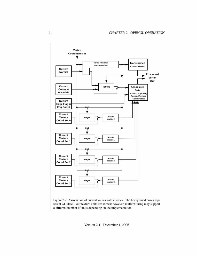
Primary and secondary colors are associated with each vertex (see section 3.9).These associated colors are either based on the current color and current secondarycolor or produced by lighting, depending on whether or not lighting is enabled.Texture and fog coordinates are similarly associated with each vertex. Multiplesets of texture coordinates may be associated with a vertex. Figure 2.2 summarizesthe association of auxiliary data with a transformed vertex to produce a processedvertex.
The current values are part of GL state. Vertices and normals are transformed,colors may be affected or replaced by lighting, and texture coordinates are trans-formed and possibly affected by a texture coordinate generation function. Theprocessing indicated for each current value is applied for each vertex that is sent tothe GL.
The methods by which vertices, normals, texture coordinates, fog coordinate,generic attributes, and colors are sent to the GL, as well as how normals are trans-formed and how vertices are mapped to the two-dimensional screen, are discussedlater.
Before colors have been assigned to a vertex, the state required by a vertexis the vertex’s coordinates, the current normal, the current edge flag (see sec-tion 2.6.2), the current material properties (see section 2.14.2), the current fog co-ordinate, the multiple generic vertex attribute sets, and the multiple current texturecoordinate sets. Because color assignment is done vertex-by-vertex, a processedvertex comprises the vertex’s coordinates, its edge flag, its fog coordinate, its as-signed colors, and its multiple texture coordinate sets.
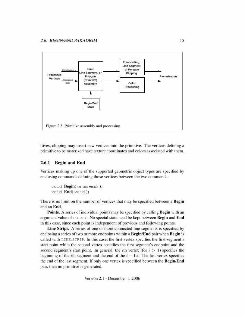
Figure 2.3 shows the sequence of operations that builds a primitive (point, linesegment, or polygon) from a sequence of vertices. After a primitive is formed, itis clipped to a viewing volume. This may alter the primitive by altering vertexcoordinates, texture coordinates, and colors. In the case of line and polygon prim-
Version 2.1 - December 1, 2006
14 CHAPTER 2. OPENGL OPERATION
CurrentEdge Flag & Fog Coord
lighting
vertex / normaltransformation
CurrentNormal
CurrentColors & Materials
AssociatedData
TransformedCoordinates
ProcessedVertex
Out
(Colors, Edge Flag,Fog and Texture
Coordinates)
VertexCoordinates In
texgen texturematrix 0
CurrentTexture
Coord Set 0
texgen texturematrix 1
CurrentTexture
Coord Set 1
texgen texturematrix 2
CurrentTexture
Coord Set 2
texgen texturematrix 3
CurrentTexture
Coord Set 3
Figure 2.2. Association of current values with a vertex. The heavy lined boxes rep-resent GL state. Four texture units are shown; however, multitexturing may supporta different number of units depending on the implementation.
Version 2.1 - December 1, 2006
2.6. BEGIN/END PARADIGM 15
ProcessedVertices
Point,Line Segment, or
Polygon(Primitive)Assembly
Begin/EndState
Point culling;Line Segment or Polygon
Clipping
ColorProcessing
Rasterization
Coordinates
AssociatedData
Figure 2.3. Primitive assembly and processing.
itives, clipping may insert new vertices into the primitive. The vertices defining aprimitive to be rasterized have texture coordinates and colors associated with them.
2.6.1 Begin and End
Vertices making up one of the supported geometric object types are specified byenclosing commands defining those vertices between the two commands
void Begin( enum mode );void End( void );
There is no limit on the number of vertices that may be specified between a Beginand an End.
Points. A series of individual points may be specified by calling Begin with anargument value of POINTS. No special state need be kept between Begin and Endin this case, since each point is independent of previous and following points.
Line Strips. A series of one or more connected line segments is specified byenclosing a series of two or more endpoints within a Begin/End pair when Begin iscalled with LINE STRIP. In this case, the first vertex specifies the first segment’sstart point while the second vertex specifies the first segment’s endpoint and thesecond segment’s start point. In general, the ith vertex (for i > 1) specifies thebeginning of the ith segment and the end of the i − 1st. The last vertex specifiesthe end of the last segment. If only one vertex is specified between the Begin/Endpair, then no primitive is generated.
Version 2.1 - December 1, 2006
16 CHAPTER 2. OPENGL OPERATION
The required state consists of the processed vertex produced from the last ver-tex that was sent (so that a line segment can be generated from it to the currentvertex), and a boolean flag indicating if the current vertex is the first vertex.
Line Loops. Line loops, specified with the LINE LOOP argument value toBegin, are the same as line strips except that a final segment is added from the finalspecified vertex to the first vertex. The additional state consists of the processedfirst vertex.
Separate Lines. Individual line segments, each specified by a pair of vertices,are generated by surrounding vertex pairs with Begin and End when the valueof the argument to Begin is LINES. In this case, the first two vertices between aBegin and End pair define the first segment, with subsequent pairs of vertices eachdefining one more segment. If the number of specified vertices is odd, then the lastone is ignored. The state required is the same as for lines but it is used differently: avertex holding the first vertex of the current segment, and a boolean flag indicatingwhether the current vertex is odd or even (a segment start or end).
Polygons. A polygon is described by specifying its boundary as a series ofline segments. When Begin is called with POLYGON, the bounding line segmentsare specified in the same way as line loops. Depending on the current state of theGL, a polygon may be rendered in one of several ways such as outlining its borderor filling its interior. A polygon described with fewer than three vertices does notgenerate a primitive.
Only convex polygons are guaranteed to be drawn correctly by the GL. If aspecified polygon is nonconvex when projected onto the window, then the renderedpolygon need only lie within the convex hull of the projected vertices defining itsboundary.
The state required to support polygons consists of at least two processed ver-tices (more than two are never required, although an implementation may usemore); this is because a convex polygon can be rasterized as its vertices arrive,before all of them have been specified. The order of the vertices is significant inlighting and polygon rasterization (see sections 2.14.1 and 3.5.1).
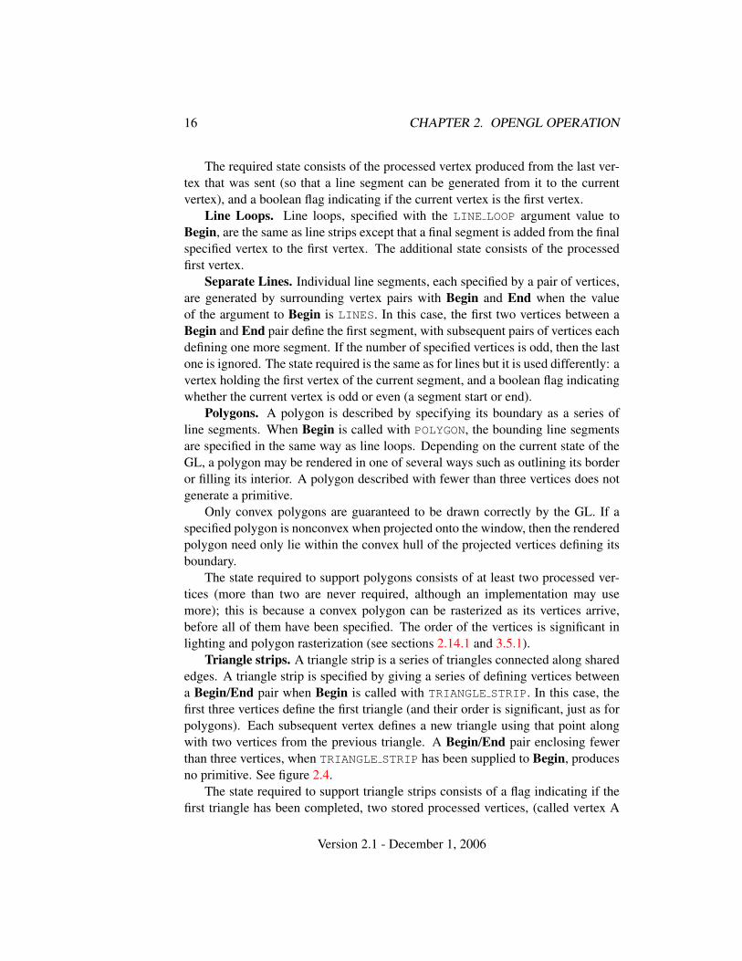
Triangle strips. A triangle strip is a series of triangles connected along sharededges. A triangle strip is specified by giving a series of defining vertices betweena Begin/End pair when Begin is called with TRIANGLE STRIP. In this case, thefirst three vertices define the first triangle (and their order is significant, just as forpolygons). Each subsequent vertex defines a new triangle using that point alongwith two vertices from the previous triangle. A Begin/End pair enclosing fewerthan three vertices, when TRIANGLE STRIP has been supplied to Begin, producesno primitive. See figure 2.4.
The state required to support triangle strips consists of a flag indicating if thefirst triangle has been completed, two stored processed vertices, (called vertex A
Version 2.1 - December 1, 2006

2.6. BEGIN/END PARADIGM 17
(a) (b) (c)
1
2
3
4
5 1
23
4
51
2
3
4
5
6
Figure 2.4. (a) A triangle strip. (b) A triangle fan. (c) Independent triangles. Thenumbers give the sequencing of the vertices between Begin and End. Note that in(a) and (b) triangle edge ordering is determined by the first triangle, while in (c) theorder of each triangle’s edges is independent of the other triangles.
and vertex B), and a one bit pointer indicating which stored vertex will be replacedwith the next vertex. After a Begin(TRIANGLE STRIP), the pointer is initializedto point to vertex A. Each vertex sent between a Begin/End pair toggles the pointer.Therefore, the first vertex is stored as vertex A, the second stored as vertex B, thethird stored as vertex A, and so on. Any vertex after the second one sent forms atriangle from vertex A, vertex B, and the current vertex (in that order).
Triangle fans. A triangle fan is the same as a triangle strip with one exception:each vertex after the first always replaces vertex B of the two stored vertices. Thevertices of a triangle fan are enclosed between Begin and End when the value ofthe argument to Begin is TRIANGLE FAN.
Separate Triangles. Separate triangles are specified by placing vertices be-tween Begin and End when the value of the argument to Begin is TRIANGLES. Inthis case, The 3i + 1st, 3i + 2nd, and 3i + 3rd vertices (in that order) determinea triangle for each i = 0, 1, . . . , n − 1, where there are 3n + k vertices betweenthe Begin and End. k is either 0, 1, or 2; if k is not zero, the final k vertices areignored. For each triangle, vertex A is vertex 3i and vertex B is vertex 3i + 1.Otherwise, separate triangles are the same as a triangle strip.
The rules given for polygons also apply to each triangle generated from a tri-angle strip, triangle fan or from separate triangles.
Quadrilateral (quad) strips. Quad strips generate a series of edge-sharingquadrilaterals from vertices appearing between Begin and End, when Begin is
Version 2.1 - December 1, 2006
18 CHAPTER 2. OPENGL OPERATION
1
2
3
4
5
6
1
2 3
4 5
6 7
8
(a) (b)
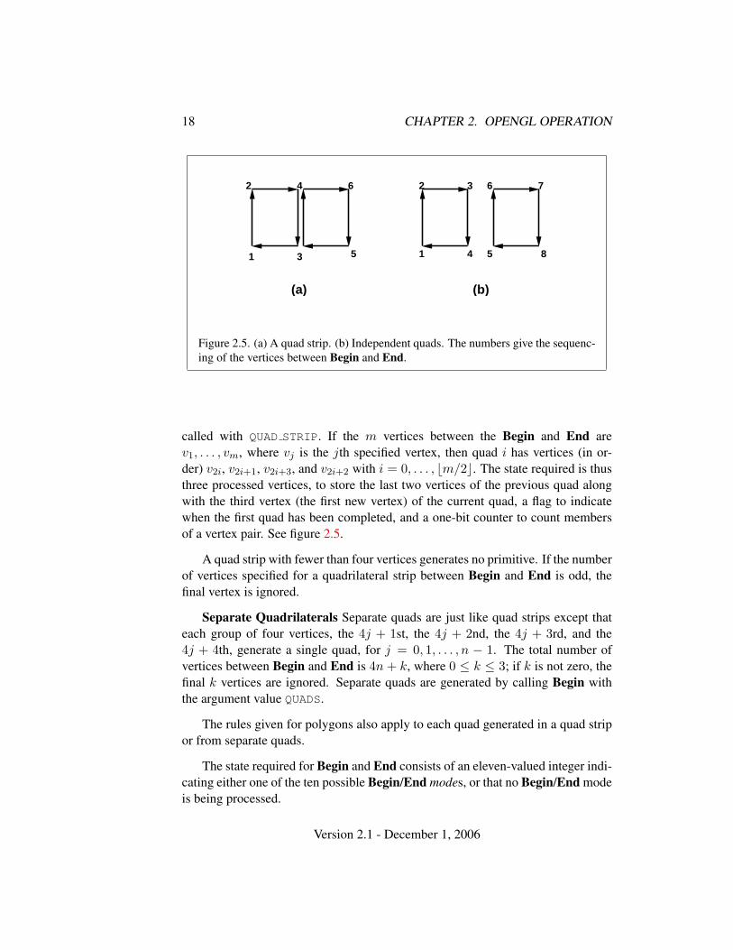
Figure 2.5. (a) A quad strip. (b) Independent quads. The numbers give the sequenc-ing of the vertices between Begin and End.
called with QUAD STRIP. If the m vertices between the Begin and End arev1, . . . , vm, where vj is the jth specified vertex, then quad i has vertices (in or-der) v2i, v2i+1, v2i+3, and v2i+2 with i = 0, . . . , bm/2c. The state required is thusthree processed vertices, to store the last two vertices of the previous quad alongwith the third vertex (the first new vertex) of the current quad, a flag to indicatewhen the first quad has been completed, and a one-bit counter to count membersof a vertex pair. See figure 2.5.
A quad strip with fewer than four vertices generates no primitive. If the numberof vertices specified for a quadrilateral strip between Begin and End is odd, thefinal vertex is ignored.
Separate Quadrilaterals Separate quads are just like quad strips except thateach group of four vertices, the 4j + 1st, the 4j + 2nd, the 4j + 3rd, and the4j + 4th, generate a single quad, for j = 0, 1, . . . , n − 1. The total number ofvertices between Begin and End is 4n + k, where 0 ≤ k ≤ 3; if k is not zero, thefinal k vertices are ignored. Separate quads are generated by calling Begin withthe argument value QUADS.
The rules given for polygons also apply to each quad generated in a quad stripor from separate quads.
The state required for Begin and End consists of an eleven-valued integer indi-cating either one of the ten possible Begin/End modes, or that no Begin/End modeis being processed.
Version 2.1 - December 1, 2006
2.6. BEGIN/END PARADIGM 19
2.6.2 Polygon Edges
Each edge of each primitive generated from a polygon, triangle strip, triangle fan,separate triangle set, quadrilateral strip, or separate quadrilateral set, is flagged aseither boundary or non-boundary. These classifications are used during polygonrasterization; some modes affect the interpretation of polygon boundary edges (seesection 3.5.4). By default, all edges are boundary edges, but the flagging of poly-gons, separate triangles, or separate quadrilaterals may be altered by calling
void EdgeFlag( boolean flag );void EdgeFlagv( boolean *flag );
to change the value of a flag bit. If flag is zero, then the flag bit is set to FALSE; ifflag is non-zero, then the flag bit is set to TRUE.
When Begin is supplied with one of the argument values POLYGON,TRIANGLES, or QUADS, each vertex specified within a Begin and End pair be-gins an edge. If the edge flag bit is TRUE, then each specified vertex begins an edgethat is flagged as boundary. If the bit is FALSE, then induced edges are flagged asnon-boundary.
The state required for edge flagging consists of one current flag bit. Initially, thebit is TRUE. In addition, each processed vertex of an assembled polygonal primitivemust be augmented with a bit indicating whether or not the edge beginning on thatvertex is boundary or non-boundary.
2.6.3 GL Commands within Begin/End
The only GL commands that are allowed within any Begin/End pairs are the com-mands for specifying vertex coordinates, vertex colors, normal coordinates, texturecoordinates, generic vertex attributes, and fog coordinates (Vertex, Color, Sec-ondaryColor, Index, Normal, TexCoord and MultiTexCoord, VertexAttrib,FogCoord), the ArrayElement command (see section 2.8), the EvalCoord andEvalPoint commands (see section 5.1), commands for specifying lighting mate-rial parameters (Material commands; see section 2.14.2), display list invocationcommands (CallList and CallLists; see section 5.4), and the EdgeFlag command.Executing any other GL command between the execution of Begin and the corre-sponding execution of End results in the error INVALID OPERATION. ExecutingBegin after Begin has already been executed but before an End is executed gen-erates the INVALID OPERATION error, as does executing End without a previouscorresponding Begin.
Execution of the commands EnableClientState, DisableClientState, Push-ClientAttrib, PopClientAttrib, ColorPointer, FogCoordPointer, EdgeFlag-
Version 2.1 - December 1, 2006
20 CHAPTER 2. OPENGL OPERATION
Pointer, IndexPointer, NormalPointer, TexCoordPointer, SecondaryCol-orPointer, VertexPointer, VertexAttribPointer, ClientActiveTexture, Inter-leavedArrays, and PixelStore is not allowed within any Begin/End pair, but anerror may or may not be generated if such execution occurs. If an error is not gen-erated, GL operation is undefined. (These commands are described in sections 2.8,3.6.1, and chapter 6.)
2.7 Vertex Specification
Vertices are specified by giving their coordinates in two, three, or four dimensions.This is done using one of several versions of the Vertex command:
void Vertex{234}{sifd}( T coords );void Vertex{234}{sifd}v( T coords );
A call to any Vertex command specifies four coordinates: x, y, z, and w. Thex coordinate is the first coordinate, y is second, z is third, and w is fourth. Acall to Vertex2 sets the x and y coordinates; the z coordinate is implicitly set tozero and the w coordinate to one. Vertex3 sets x, y, and z to the provided valuesand w to one. Vertex4 sets all four coordinates, allowing the specification of anarbitrary point in projective three-space. Invoking a Vertex command outside of aBegin/End pair results in undefined behavior.
Current values are used in associating auxiliary data with a vertex as describedin section 2.6. A current value may be changed at any time by issuing an appropri-ate command. The commands
void TexCoord{1234}{sifd}( T coords );void TexCoord{1234}{sifd}v( T coords );
specify the current homogeneous texture coordinates, named s, t, r, and q. TheTexCoord1 family of commands set the s coordinate to the provided single argu-ment while setting t and r to 0 and q to 1. Similarly, TexCoord2 sets s and t to thespecified values, r to 0 and q to 1; TexCoord3 sets s, t, and r, with q set to 1, andTexCoord4 sets all four texture coordinates.
Implementations must support at least two sets of texture coordinates. Thecommands
void MultiTexCoord{1234}{sifd}(enum texture,T coords)void MultiTexCoord{1234}{sifd}v(enum texture,T
coords)
Version 2.1 - December 1, 2006
2.7. VERTEX SPECIFICATION 21
take the coordinate set to be modified as the texture parameter. texture is a symbolicconstant of the form TEXTUREi, indicating that texture coordinate set i is to bemodified. The constants obey TEXTUREi = TEXTURE0 + i (i is in the range 0 tok− 1, where k is the implementation-dependent number of texture coordinate setsdefined by MAX TEXTURE COORDS).
The TexCoord commands are exactly equivalent to the corresponding Multi-TexCoord commands with texture set to TEXTURE0.
Gets of CURRENT TEXTURE COORDS return the texture coordinate set definedby the value of ACTIVE TEXTURE.
Specifying an invalid texture coordinate set for the texture argument of Multi-TexCoord results in undefined behavior.
The current normal is set using
void Normal3{bsifd}( T coords );void Normal3{bsifd}v( T coords );
Byte, short, or integer values passed to Normal are converted to floating-pointvalues as indicated for the corresponding (signed) type in table 2.9.
The current fog coordinate is set using
void FogCoord{fd}( T coord );void FogCoord{fd}v( T coord );
There are several ways to set the current color and secondary color. The GLstores a current single-valued color index, as well as a current four-valued RGBAcolor and secondary color. Either the index or the color and secondary color aresignificant depending as the GL is in color index mode or RGBA mode. The modeselection is made when the GL is initialized.
The commands to set RGBA colors are
void Color{34}{bsifd ubusui}( T components );void Color{34}{bsifd ubusui}v( T components );void SecondaryColor3{bsifd ubusui}( T components );void SecondaryColor3{bsifd ubusui}v( T components );
The Color command has two major variants: Color3 and Color4. The four valueversions set all four values. The three value versions set R, G, and B to the providedvalues; A is set to 1.0. (The conversion of integer color components (R, G, B, andA) to floating-point values is discussed in section 2.14.)
The secondary color has only the three value versions. Secondary A is alwaysset to 1.0.
Version 2.1 - December 1, 2006
22 CHAPTER 2. OPENGL OPERATION
Versions of the Color and SecondaryColor commands that take floating-pointvalues accept values nominally between 0.0 and 1.0. 0.0 corresponds to the min-imum while 1.0 corresponds to the maximum (machine dependent) value that acomponent may take on in the framebuffer (see section 2.14 on colors and color-ing). Values outside [0, 1] are not clamped.
The command
void Index{sifd ub}( T index );void Index{sifd ub}v( T index );
updates the current (single-valued) color index. It takes one argument, the valueto which the current color index should be set. Values outside the (machine-dependent) representable range of color indices are not clamped.
Vertex shaders (see section 2.15) can be written to access an array of 4-component generic vertex attributes in addition to the conventional attributes spec-ified previously. The first slot of this array is numbered 0, and the size of the arrayis specified by the implementation-dependent constant MAX VERTEX ATTRIBS.
The commands
void VertexAttrib{1234}{sfd}( uint index, T values );void VertexAttrib{123}{sfd}v( uint index, T values );void VertexAttrib4{bsifd ubusui}v( uint index, T values );
can be used to load the given value(s) into the generic attribute at slot index, whosecomponents are named x, y, z, and w. The VertexAttrib1* family of commandssets the x coordinate to the provided single argument while setting y and z to 0 andw to 1. Similarly, VertexAttrib2* commands set x and y to the specified values,z to 0 and w to 1; VertexAttrib3* commands set x, y, and z, with w set to 1, andVertexAttrib4* commands set all four coordinates. The error INVALID VALUE isgenerated if index is greater than or equal to MAX VERTEX ATTRIBS.
The commands
void VertexAttrib4Nub( uint index, T values );void VertexAttrib4N{bsi ubusui}v( uint index, T values );
also specify vertex attributes with fixed-point coordinates that are scaled to a nor-malized range, according to table 2.9.
The VertexAttrib* entry points defined earlier can also be used to load at-tributes declared as a matrix in a vertex shader. Each column of a matrix takes upone generic 4-component attribute slot out of the MAX VERTEX ATTRIBS available
Version 2.1 - December 1, 2006
2.8. VERTEX ARRAYS 23
slots. Matrices are loaded into these slots in column major order. Matrix columnsneed to be loaded in increasing slot numbers.
Setting generic vertex attribute zero specifies a vertex; the four vertex coordi-nates are taken from the values of attribute zero. A Vertex2, Vertex3, or Vertex4command is completely equivalent to the corresponding VertexAttrib* commandwith an index of zero. Setting any other generic vertex attribute updates the currentvalues of the attribute. There are no current values for vertex attribute zero.
There is no aliasing among generic attributes and conventional attributes. Inother words, an application can set all MAX VERTEX ATTRIBS generic attributesand all conventional attributes without fear of one particular attribute overwritingthe value of another attribute.
The state required to support vertex specification consists of four floating-pointnumbers per texture coordinate set to store the current texture coordinates s, t, r,and q, three floating-point numbers to store the three coordinates of the currentnormal, one floating-point number to store the current fog coordinate, four floating-point values to store the current RGBA color, four floating-point values to store thecurrent RGBA secondary color, one floating-point value to store the current colorindex, and MAX VERTEX ATTRIBS − 1 four-component floating-point vectors tostore generic vertex attributes.
There is no notion of a current vertex, so no state is devoted to vertex coor-dinates or generic attribute zero. The initial texture coordinates are (s, t, r, q) =(0, 0, 0, 1) for each texture coordinate set. The initial current normal has coor-dinates (0, 0, 1). The initial fog coordinate is zero. The initial RGBA color is(R,G,B,A) = (1, 1, 1, 1) and the initial RGBA secondary color is (0, 0, 0, 1).The initial color index is 1. The initial values for all generic vertex attributes are(0, 0, 0, 1).
2.8 Vertex Arrays
The vertex specification commands described in section 2.7 accept data in almostany format, but their use requires many command executions to specify even sim-ple geometry. Vertex data may also be placed into arrays that are stored in theclient’s address space. Blocks of data in these arrays may then be used to spec-ify multiple geometric primitives through the execution of a single GL command.The client may specify up to seven plus the values of MAX TEXTURE COORDS andMAX VERTEX ATTRIBS arrays: one each to store vertex coordinates, normals, col-ors, secondary colors, color indices, edge flags, fog coordinates, two or more tex-ture coordinate sets, and one or more generic vertex attributes. The commands
Version 2.1 - December 1, 2006
24 CHAPTER 2. OPENGL OPERATION
void VertexPointer( int size, enum type, sizei stride,void *pointer );
void NormalPointer( enum type, sizei stride,void *pointer );
void ColorPointer( int size, enum type, sizei stride,void *pointer );
void SecondaryColorPointer( int size, enum type,sizei stride, void *pointer );
void IndexPointer( enum type, sizei stride, void *pointer );
void EdgeFlagPointer( sizei stride, void *pointer );
void FogCoordPointer( enum type, sizei stride,void *pointer );
void TexCoordPointer( int size, enum type, sizei stride,void *pointer );
void VertexAttribPointer( uint index, int size, enum type,boolean normalized, sizei stride, constvoid *pointer );
describe the locations and organizations of these arrays. For each command,type specifies the data type of the values stored in the array. Because edge flagsare always type boolean, EdgeFlagPointer has no type argument. size, whenpresent, indicates the number of values per vertex that are stored in the array.Because normals are always specified with three values, NormalPointer has nosize argument. Likewise, because color indices and edge flags are always spec-ified with a single value, IndexPointer and EdgeFlagPointer also have no sizeargument. Table 2.4 indicates the allowable values for size and type (whenpresent). For type the values BYTE, SHORT, INT, FLOAT, and DOUBLE indicatetypes byte, short, int, float, and double, respectively; and the valuesUNSIGNED BYTE, UNSIGNED SHORT, and UNSIGNED INT indicate types ubyte,ushort, and uint, respectively. The error INVALID VALUE is generated if sizeis specified with a value other than that indicated in the table.
The index parameter in the VertexAttribPointer command identifies thegeneric vertex attribute array being described. The error INVALID VALUE is gener-ated if index is greater than or equal to MAX VERTEX ATTRIBS. The normalized pa-rameter in the VertexAttribPointer command identifies whether fixed-point types
Version 2.1 - December 1, 2006
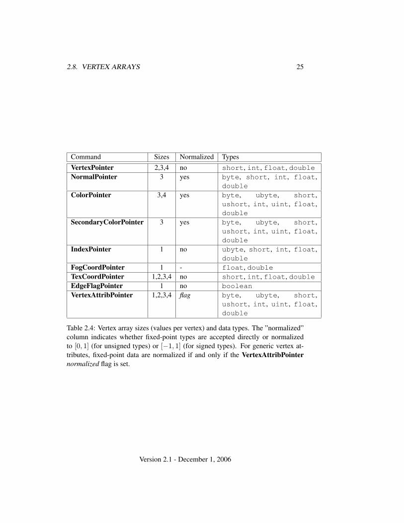
2.8. VERTEX ARRAYS 25
Command Sizes Normalized TypesVertexPointer 2,3,4 no short, int, float, doubleNormalPointer 3 yes byte, short, int, float,
doubleColorPointer 3,4 yes byte, ubyte, short,
ushort, int, uint, float,double
SecondaryColorPointer 3 yes byte, ubyte, short,ushort, int, uint, float,double
IndexPointer 1 no ubyte, short, int, float,double
FogCoordPointer 1 - float, doubleTexCoordPointer 1,2,3,4 no short, int, float, doubleEdgeFlagPointer 1 no booleanVertexAttribPointer 1,2,3,4 flag byte, ubyte, short,
ushort, int, uint, float,double
Table 2.4: Vertex array sizes (values per vertex) and data types. The ”normalized”column indicates whether fixed-point types are accepted directly or normalizedto [0, 1] (for unsigned types) or [−1, 1] (for signed types). For generic vertex at-tributes, fixed-point data are normalized if and only if the VertexAttribPointernormalized flag is set.
Version 2.1 - December 1, 2006
26 CHAPTER 2. OPENGL OPERATION
should be normalized when converted to floating-point. If normalized is TRUE,fixed-point data are converted as specified in table 2.9; otherwise, the fixed-pointvalues are converted directly.
The one, two, three, or four values in an array that correspond to a single vertexcomprise an array element. The values within each array element are stored se-quentially in memory. If stride is specified as zero, then array elements are storedsequentially as well. The error INVALID VALUE is generated if stride is negative.Otherwise pointers to the ith and (i + 1)st elements of an array differ by stridebasic machine units (typically unsigned bytes), the pointer to the (i + 1)st elementbeing greater. For each command, pointer specifies the location in memory of thefirst value of the first element of the array being specified.
An individual array is enabled or disabled by calling one of
void EnableClientState( enum array );void DisableClientState( enum array );
with array set to VERTEX ARRAY, NORMAL ARRAY, COLOR ARRAY,SECONDARY COLOR ARRAY, INDEX ARRAY, EDGE FLAG ARRAY,FOG COORD ARRAY, or TEXTURE COORD ARRAY, for the vertex, normal, color,secondary color, color index, edge flag, fog coordinate, or texture coordinate array,respectively.
An individual generic vertex attribute array is enabled or disabled by callingone of
void EnableVertexAttribArray( uint index );void DisableVertexAttribArray( uint index );
where index identifies the generic vertex attribute array to enable or disable.The error INVALID VALUE is generated if index is greater than or equal toMAX VERTEX ATTRIBS.
The command
void ClientActiveTexture( enum texture );
is used to select the vertex array client state parameters to be modified bythe TexCoordPointer command and the array affected by EnableClientState andDisableClientState with parameter TEXTURE COORD ARRAY. This command setsthe client state variable CLIENT ACTIVE TEXTURE. Each texture coordinate sethas a client state vector which is selected when this command is invoked. Thisstate vector includes the vertex array state. This call also selects the texture coor-dinate set state used for queries of client state.
Version 2.1 - December 1, 2006
2.8. VERTEX ARRAYS 27
Specifying an invalid texture generates the error INVALID ENUM. Valid valuesof texture are the same as for the MultiTexCoord commands described in sec-tion 2.7.
The command
void ArrayElement( int i );
transfers the ith element of every enabled array to the GL. The effect ofArrayElement(i) is the same as the effect of the command sequence
if (normal array enabled)Normal3[type]v(normal array element i);
if (color array enabled)Color[size][type]v(color array element i);
if (secondary color array enabled)SecondaryColor3[type]v(secondary color array element i);
if (fog coordinate array enabled)FogCoord[type]v(fog coordinate array element i);
for (j = 0; j < textureUnits; j++) {if (texture coordinate set j array enabled)
MultiTexCoord[size][type]v(TEXTURE0 + j, texture coordinate set j array element i);if (color index array enabled)
Index[type]v(color index array element i);if (edge flag array enabled)
EdgeFlagv(edge flag array element i);for (j = 1; j < genericAttributes; j++) {if (generic vertex attribute j array enabled) {if (generic vertex attribute j array normalization flag is set, and
type is not FLOAT or DOUBLE)VertexAttrib[size]N[type]v(j, generic vertex attribute j array element i);
elseVertexAttrib[size][type]v(j, generic vertex attribute j array element i);
}}if (generic attribute array 0 enabled) {if (generic vertex attribute 0 array normalization flag is set, and
type is not FLOAT or DOUBLE)VertexAttrib[size]N[type]v(0, generic vertex attribute 0 array element i);
elseVertexAttrib[size][type]v(0, generic vertex attribute 0 array element i);
Version 2.1 - December 1, 2006
28 CHAPTER 2. OPENGL OPERATION
} else if (vertex array enabled) {Vertex[size][type]v(vertex array element i);
}
where textureUnits and genericAttributes give the number of texture coordinatesets and generic vertex attributes supported by the implementation, respectively.”[size]” and ”[type]” correspond to the size and type of the corresponding array.For generic vertex attributes, it is assumed that a complete set of vertex attributecommands exists, even though not all such functions are provided by the GL.
Changes made to array data between the execution of Begin and the corre-sponding execution of End may affect calls to ArrayElement that are made withinthe same Begin/End period in non-sequential ways. That is, a call to ArrayEle-ment that precedes a change to array data may access the changed data, and a callthat follows a change to array data may access original data.
Specifying i < 0 results in undefined behavior. Generating the errorINVALID VALUE is recommended in this case.
The command
void DrawArrays( enum mode, int first, sizei count );
constructs a sequence of geometric primitives using elements first throughfirst + count − 1 of each enabled array. mode specifies what kind of primi-tives are constructed; it accepts the same token values as the mode parameter ofthe Begin command. The effect of
DrawArrays (mode, first, count);
is the same as the effect of the command sequence
if (mode or count is invalid )generate appropriate error
else {Begin(mode);for (int i = 0; i < count ; i++)
ArrayElement(first+ i);End();
}
with one exception: the current normal coordinates, color, secondary color, colorindex, edge flag, fog coordinate, texture coordinates, and generic attributes areeach indeterminate after execution of DrawArrays, if the corresponding array is
Version 2.1 - December 1, 2006
2.8. VERTEX ARRAYS 29
enabled. Current values corresponding to disabled arrays are not modified by theexecution of DrawArrays.
Specifying first < 0 results in undefined behavior. Generating the errorINVALID VALUE is recommended in this case.
The command
void MultiDrawArrays( enum mode, int *first,sizei *count, sizei primcount );
behaves identically to DrawArrays except that primcount separate ranges ofelements are specified instead. It has the same effect as:
for (i = 0; i < primcount; i++) {if (count[i] > 0)
DrawArrays(mode, first[i], count[i]);}
The command
void DrawElements( enum mode, sizei count, enum type,void *indices );
constructs a sequence of geometric primitives using the count elementswhose indices are stored in indices. type must be one of UNSIGNED BYTE,UNSIGNED SHORT, or UNSIGNED INT, indicating that the values in indices are in-dices of GL type ubyte, ushort, or uint respectively. mode specifies whatkind of primitives are constructed; it accepts the same token values as the modeparameter of the Begin command. The effect of
DrawElements (mode, count, type, indices);
is the same as the effect of the command sequence
if (mode, count, or type is invalid )generate appropriate error
else {Begin(mode);for (int i = 0; i < count ; i++)
ArrayElement(indices[i]);End();
}
Version 2.1 - December 1, 2006
30 CHAPTER 2. OPENGL OPERATION
with one exception: the current normal coordinates, color, secondary color, colorindex, edge flag, fog coordinate, texture coordinates, and generic attributes are eachindeterminate after the execution of DrawElements, if the corresponding array isenabled. Current values corresponding to disabled arrays are not modified by theexecution of DrawElements.
The command
void MultiDrawElements( enum mode, sizei *count,enum type, void **indices, sizei primcount );
behaves identically to DrawElements except that primcount separate lists ofelements are specified instead. It has the same effect as:
for (i = 0; i < primcount; i++) {if (count[i]) > 0)
DrawElements(mode, count[i], type, indices[i]);}
The command
void DrawRangeElements( enum mode, uint start,uint end, sizei count, enum type, void *indices );
is a restricted form of DrawElements. mode, count, type, and indices match thecorresponding arguments to DrawElements, with the additional constraint that allvalues in the array indices must lie between start and end inclusive.
Implementations denote recommended maximum amounts of vertex and indexdata, which may be queried by calling GetIntegerv with the symbolic constantsMAX ELEMENTS VERTICES and MAX ELEMENTS INDICES. If end − start + 1 isgreater than the value of MAX ELEMENTS VERTICES, or if count is greater thanthe value of MAX ELEMENTS INDICES, then the call may operate at reduced per-formance. There is no requirement that all vertices in the range [start, end] bereferenced. However, the implementation may partially process unused vertices,reducing performance from what could be achieved with an optimal index set.
The error INVALID VALUE is generated if end < start. Invalid mode, count,or type parameters generate the same errors as would the corresponding call toDrawElements. It is an error for indices to lie outside the range [start, end], butimplementations may not check for this. Such indices will cause implementation-dependent behavior.
The command
Version 2.1 - December 1, 2006
2.8. VERTEX ARRAYS 31
void InterleavedArrays( enum format, sizei stride,void *pointer );
efficiently initializes the six arrays and their enables to one of 14 con-figurations. format must be one of 14 symbolic constants: V2F,V3F, C4UB V2F, C4UB V3F, C3F V3F, N3F V3F, C4F N3F V3F, T2F V3F,T4F V4F, T2F C4UB V3F, T2F C3F V3F, T2F N3F V3F, T2F C4F N3F V3F, orT4F C4F N3F V4F.
The effect of
InterleavedArrays(format, stride, pointer);
is the same as the effect of the command sequence
if (format or stride is invalid)generate appropriate error
else {int str;set et, ec, en, st, sc, sv, tc, pc, pn, pv, and s as a function
of table 2.5 and the value of format.str = stride;if (str is zero)str = s;
DisableClientState(EDGE FLAG ARRAY);DisableClientState(INDEX ARRAY);DisableClientState(SECONDARY COLOR ARRAY);DisableClientState(FOG COORD ARRAY);if (et) {
EnableClientState(TEXTURE COORD ARRAY);TexCoordPointer(st, FLOAT, str, pointer);
} elseDisableClientState(TEXTURE COORD ARRAY);
if (ec) {EnableClientState(COLOR ARRAY);ColorPointer(sc, tc, str, pointer + pc);
} elseDisableClientState(COLOR ARRAY);
if (en) {EnableClientState(NORMAL ARRAY);NormalPointer(FLOAT, str, pointer + pn);
} else
Version 2.1 - December 1, 2006
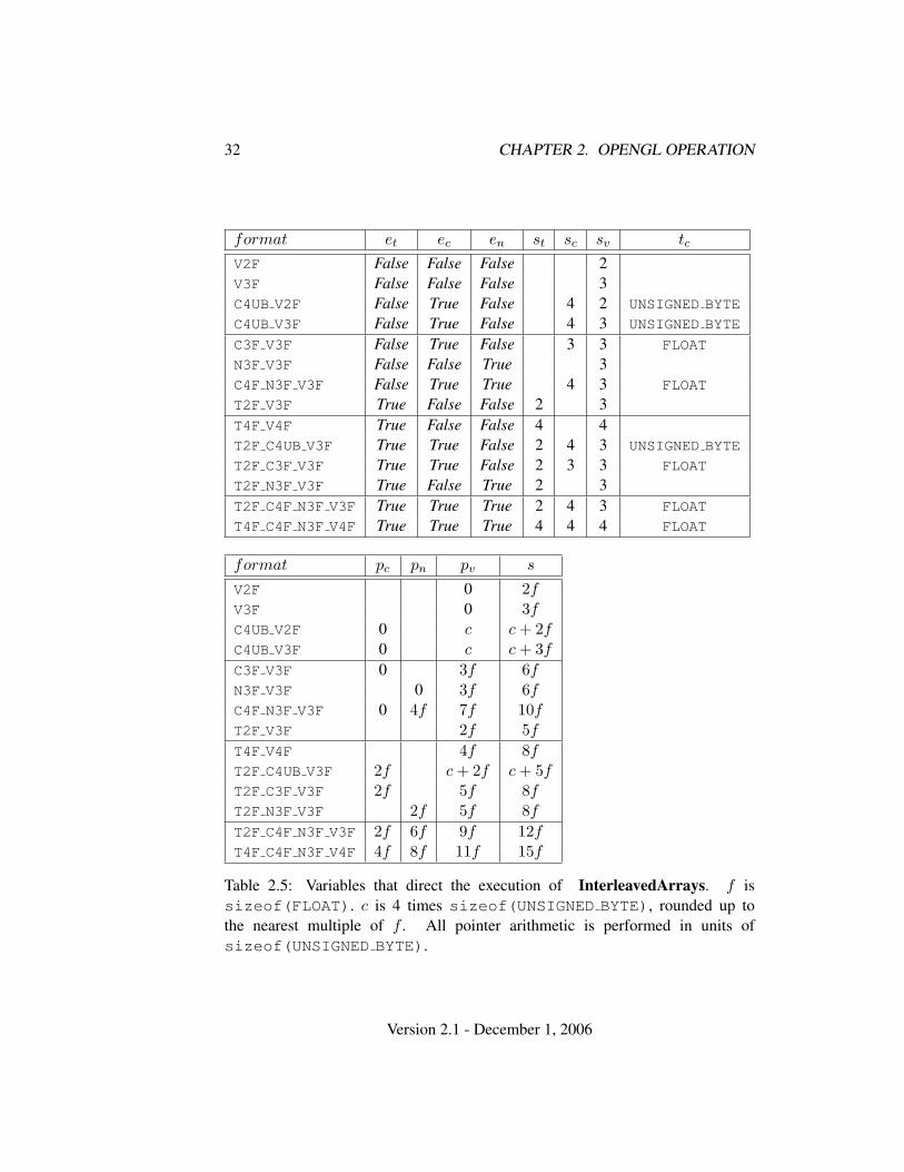
32 CHAPTER 2. OPENGL OPERATION
format et ec en st sc sv tc
V2F False False False 2V3F False False False 3C4UB V2F False True False 4 2 UNSIGNED BYTE
C4UB V3F False True False 4 3 UNSIGNED BYTE
C3F V3F False True False 3 3 FLOAT
N3F V3F False False True 3C4F N3F V3F False True True 4 3 FLOAT
T2F V3F True False False 2 3T4F V4F True False False 4 4T2F C4UB V3F True True False 2 4 3 UNSIGNED BYTE
T2F C3F V3F True True False 2 3 3 FLOAT
T2F N3F V3F True False True 2 3T2F C4F N3F V3F True True True 2 4 3 FLOAT
T4F C4F N3F V4F True True True 4 4 4 FLOAT
format pc pn pv s
V2F 0 2fV3F 0 3fC4UB V2F 0 c c + 2fC4UB V3F 0 c c + 3f
C3F V3F 0 3f 6fN3F V3F 0 3f 6fC4F N3F V3F 0 4f 7f 10fT2F V3F 2f 5f
T4F V4F 4f 8fT2F C4UB V3F 2f c + 2f c + 5fT2F C3F V3F 2f 5f 8fT2F N3F V3F 2f 5f 8f
T2F C4F N3F V3F 2f 6f 9f 12fT4F C4F N3F V4F 4f 8f 11f 15f
Table 2.5: Variables that direct the execution of InterleavedArrays. f issizeof(FLOAT). c is 4 times sizeof(UNSIGNED BYTE), rounded up tothe nearest multiple of f . All pointer arithmetic is performed in units ofsizeof(UNSIGNED BYTE).
Version 2.1 - December 1, 2006

2.9. BUFFER OBJECTS 33
DisableClientState(NORMAL ARRAY);EnableClientState(VERTEX ARRAY);VertexPointer(sv, FLOAT, str, pointer + pv);
}
If the number of supported texture units (the value of MAX TEXTURE COORDS)is m and the number of supported generic vertex attributes (the value ofMAX VERTEX ATTRIBS) is n, then the client state required to implement vertexarrays consists of an integer for the client active texture unit selector, 7 + m + nboolean values, 7 + m + n memory pointers, 7 + m + n integer stride values,7 + m + n symbolic constants representing array types, 3 + m + n integers repre-senting values per element, and n boolean values indicating normalization. In theinitial state, the client active texture unit selector is TEXTURE0, the boolean valuesare each false, the memory pointers are each NULL, the strides are each zero, thearray types are each FLOAT, and the integers representing values per element areeach four.
2.9 Buffer Objects
The vertex data arrays described in section 2.8 are stored in client memory. Itis sometimes desirable to store frequently used client data, such as vertex arrayand pixel data, in high-performance server memory. GL buffer objects provide amechanism that clients can use to allocate, initialize, and render from such memory.
The name space for buffer objects is the unsigned integers, with zero reservedfor the GL. A buffer object is created by binding an unused name to a buffer target.The binding is effected by calling
void BindBuffer( enum target, uint buffer );
target must be one of ARRAY BUFFER, ELEMENT ARRAY BUFFER,PIXEL UNPACK BUFFER, or PIXEL PACK BUFFER. The ARRAY BUFFER target isdiscussed in section 2.9.1. The ELEMENT ARRAY BUFFER target is discussed insection 2.9.2. The PIXEL UNPACK BUFFER and PIXEL PACK BUFFER targets arediscussed later in sections 3.6, 4.3.2, and 6.1. If the buffer object named buffer hasnot been previously bound or has been deleted since the last binding, the GL cre-ates a new state vector, initialized with a zero-sized memory buffer and comprisingthe state values listed in table 2.6.
BindBuffer may also be used to bind an existing buffer object. If the bind issuccessful no change is made to the state of the newly bound buffer object, and anyprevious binding to target is broken.
Version 2.1 - December 1, 2006
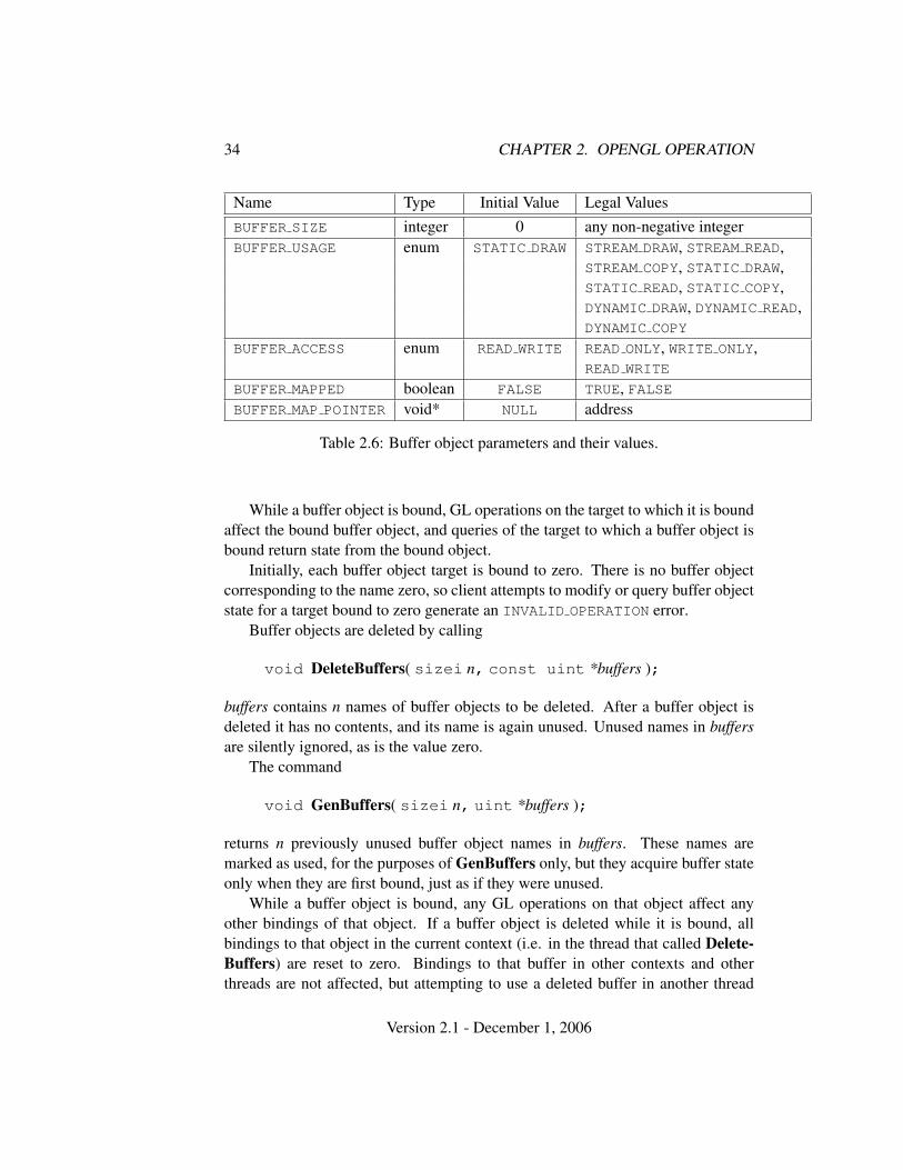
34 CHAPTER 2. OPENGL OPERATION
Name Type Initial Value Legal ValuesBUFFER SIZE integer 0 any non-negative integerBUFFER USAGE enum STATIC DRAW STREAM DRAW, STREAM READ,
STREAM COPY, STATIC DRAW,STATIC READ, STATIC COPY,DYNAMIC DRAW, DYNAMIC READ,DYNAMIC COPY
BUFFER ACCESS enum READ WRITE READ ONLY, WRITE ONLY,READ WRITE
BUFFER MAPPED boolean FALSE TRUE, FALSEBUFFER MAP POINTER void* NULL address
Table 2.6: Buffer object parameters and their values.
While a buffer object is bound, GL operations on the target to which it is boundaffect the bound buffer object, and queries of the target to which a buffer object isbound return state from the bound object.
Initially, each buffer object target is bound to zero. There is no buffer objectcorresponding to the name zero, so client attempts to modify or query buffer objectstate for a target bound to zero generate an INVALID OPERATION error.
Buffer objects are deleted by calling
void DeleteBuffers( sizei n, const uint *buffers );
buffers contains n names of buffer objects to be deleted. After a buffer object isdeleted it has no contents, and its name is again unused. Unused names in buffersare silently ignored, as is the value zero.
The command
void GenBuffers( sizei n, uint *buffers );
returns n previously unused buffer object names in buffers. These names aremarked as used, for the purposes of GenBuffers only, but they acquire buffer stateonly when they are first bound, just as if they were unused.
While a buffer object is bound, any GL operations on that object affect anyother bindings of that object. If a buffer object is deleted while it is bound, allbindings to that object in the current context (i.e. in the thread that called Delete-Buffers) are reset to zero. Bindings to that buffer in other contexts and otherthreads are not affected, but attempting to use a deleted buffer in another thread
Version 2.1 - December 1, 2006
2.9. BUFFER OBJECTS 35
produces undefined results, including but not limited to possible GL errors andrendering corruption. Using a deleted buffer in another context or thread may not,however, result in program termination.
The data store of a buffer object is created and initialized by calling
void BufferData( enum target, sizeiptr size, constvoid *data, enum usage );
with target set to one of ARRAY BUFFER, ELEMENT ARRAY BUFFER,PIXEL UNPACK BUFFER, or PIXEL PACK BUFFER, size set to the size of the datastore in basic machine units, and data pointing to the source data in client memory.If data is non-null, then the source data is copied to the buffer object’s data store.If data is null, then the contents of the buffer object’s data store are undefined.
usage is specified as one of nine enumerated values, indicating the expectedapplication usage pattern of the data store. The values are:
STREAM DRAW The data store contents will be specified once by the application,and used at most a few times as the source for GL drawing and image speci-fication commands.
STREAM READ The data store contents will be specified once by reading datafrom the GL, and queried at most a few times by the application.
STREAM COPY The data store contents will be specified once by reading datafrom the GL, and used at most a few times as the source for GL drawing andimage specification commands.
STATIC DRAW The data store contents will be specified once by the application,and used many times as the source for GL drawing and image specificationcommands.
STATIC READ The data store contents will be specified once by reading datafrom the GL, and queried many times by the application.
STATIC COPY The data store contents will be specified once by reading datafrom the GL, and used many times as the source for GL drawing and imagespecification commands.
DYNAMIC DRAW The data store contents will be respecified repeatedly by the ap-plication, and used many times as the source for GL drawing and imagespecification commands.
Version 2.1 - December 1, 2006
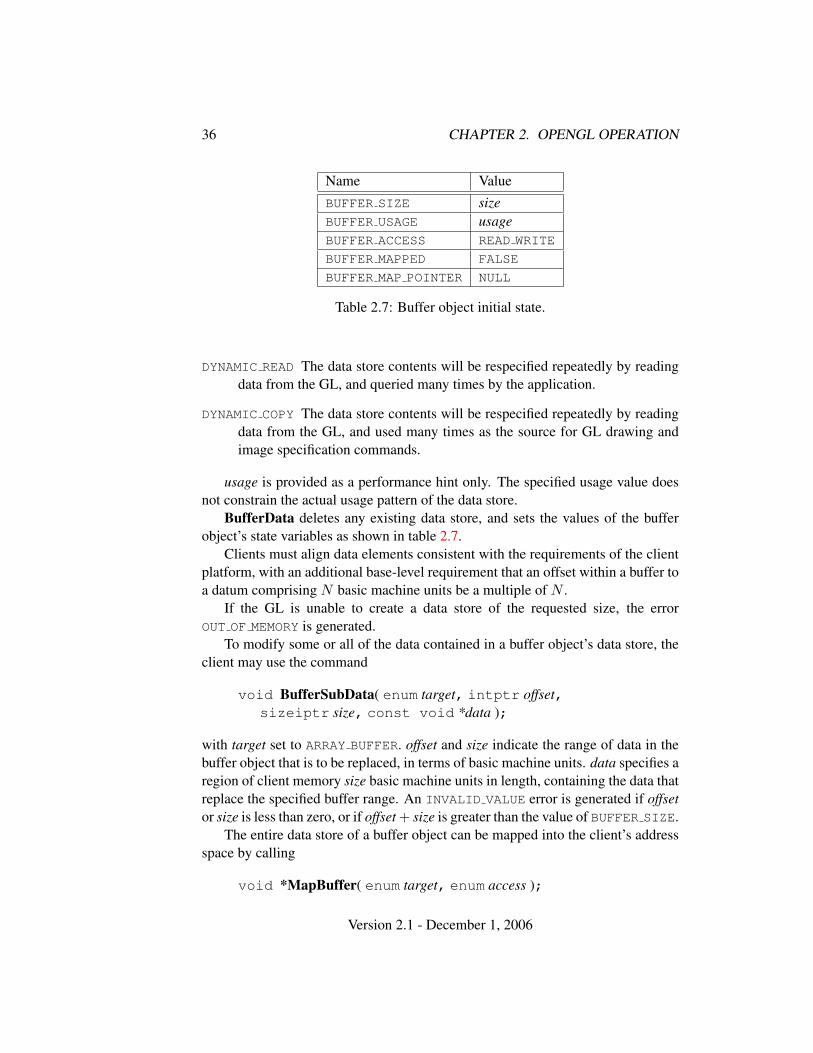
36 CHAPTER 2. OPENGL OPERATION
Name ValueBUFFER SIZE sizeBUFFER USAGE usageBUFFER ACCESS READ WRITE
BUFFER MAPPED FALSE
BUFFER MAP POINTER NULL
Table 2.7: Buffer object initial state.
DYNAMIC READ The data store contents will be respecified repeatedly by readingdata from the GL, and queried many times by the application.
DYNAMIC COPY The data store contents will be respecified repeatedly by readingdata from the GL, and used many times as the source for GL drawing andimage specification commands.
usage is provided as a performance hint only. The specified usage value doesnot constrain the actual usage pattern of the data store.
BufferData deletes any existing data store, and sets the values of the bufferobject’s state variables as shown in table 2.7.
Clients must align data elements consistent with the requirements of the clientplatform, with an additional base-level requirement that an offset within a buffer toa datum comprising N basic machine units be a multiple of N .
If the GL is unable to create a data store of the requested size, the errorOUT OF MEMORY is generated.
To modify some or all of the data contained in a buffer object’s data store, theclient may use the command
void BufferSubData( enum target, intptr offset,sizeiptr size, const void *data );
with target set to ARRAY BUFFER. offset and size indicate the range of data in thebuffer object that is to be replaced, in terms of basic machine units. data specifies aregion of client memory size basic machine units in length, containing the data thatreplace the specified buffer range. An INVALID VALUE error is generated if offsetor size is less than zero, or if offset + size is greater than the value of BUFFER SIZE.
The entire data store of a buffer object can be mapped into the client’s addressspace by calling
void *MapBuffer( enum target, enum access );
Version 2.1 - December 1, 2006
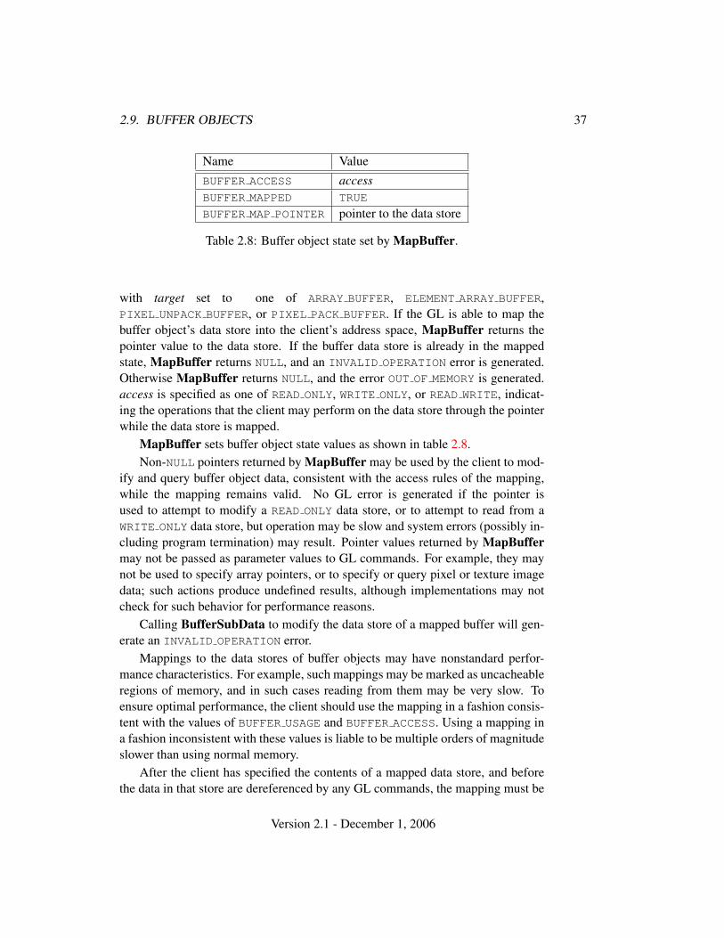
2.9. BUFFER OBJECTS 37
Name ValueBUFFER ACCESS accessBUFFER MAPPED TRUE
BUFFER MAP POINTER pointer to the data store
Table 2.8: Buffer object state set by MapBuffer.
with target set to one of ARRAY BUFFER, ELEMENT ARRAY BUFFER,PIXEL UNPACK BUFFER, or PIXEL PACK BUFFER. If the GL is able to map thebuffer object’s data store into the client’s address space, MapBuffer returns thepointer value to the data store. If the buffer data store is already in the mappedstate, MapBuffer returns NULL, and an INVALID OPERATION error is generated.Otherwise MapBuffer returns NULL, and the error OUT OF MEMORY is generated.access is specified as one of READ ONLY, WRITE ONLY, or READ WRITE, indicat-ing the operations that the client may perform on the data store through the pointerwhile the data store is mapped.
MapBuffer sets buffer object state values as shown in table 2.8.Non-NULL pointers returned by MapBuffer may be used by the client to mod-
ify and query buffer object data, consistent with the access rules of the mapping,while the mapping remains valid. No GL error is generated if the pointer isused to attempt to modify a READ ONLY data store, or to attempt to read from aWRITE ONLY data store, but operation may be slow and system errors (possibly in-cluding program termination) may result. Pointer values returned by MapBuffermay not be passed as parameter values to GL commands. For example, they maynot be used to specify array pointers, or to specify or query pixel or texture imagedata; such actions produce undefined results, although implementations may notcheck for such behavior for performance reasons.
Calling BufferSubData to modify the data store of a mapped buffer will gen-erate an INVALID OPERATION error.
Mappings to the data stores of buffer objects may have nonstandard perfor-mance characteristics. For example, such mappings may be marked as uncacheableregions of memory, and in such cases reading from them may be very slow. Toensure optimal performance, the client should use the mapping in a fashion consis-tent with the values of BUFFER USAGE and BUFFER ACCESS. Using a mapping ina fashion inconsistent with these values is liable to be multiple orders of magnitudeslower than using normal memory.
After the client has specified the contents of a mapped data store, and beforethe data in that store are dereferenced by any GL commands, the mapping must be
Version 2.1 - December 1, 2006
38 CHAPTER 2. OPENGL OPERATION
relinquished by calling
boolean UnmapBuffer( enum target );
with target set to one of ARRAY BUFFER, ELEMENT ARRAY BUFFER,PIXEL UNPACK BUFFER, or PIXEL PACK BUFFER. Unmapping a mapped bufferobject invalidates the pointers to its data store and sets the object’sBUFFER MAPPED state to FALSE and its BUFFER MAP POINTER state to NULL.
UnmapBuffer returns TRUE unless data values in the buffer’s data store havebecome corrupted during the period that the buffer was mapped. Such corruptioncan be the result of a screen resolution change or other window-system-dependentevent that causes system heaps such as those for high-performance graphics mem-ory to be discarded. GL implementations must guarantee that such corruption canoccur only during the periods that a buffer’s data store is mapped. If such corrup-tion has occurred, UnmapBuffer returns FALSE, and the contents of the buffer’sdata store become undefined.
If the buffer data store is already in the unmapped state, UnmapBuffer returnsFALSE, and an INVALID OPERATION error is generated. However, unmappingthat occurs as a side effect of buffer deletion or reinitialization is not an error.
2.9.1 Vertex Arrays in Buffer Objects
Blocks of vertex array data may be stored in buffer objects with the same formatand layout options supported for client-side vertex arrays. However, it is expectedthat GL implementations will (at minimum) be optimized for data with all compo-nents represented as floats, as well as for color data with components representedas either floats or unsigned bytes.
A buffer object binding point is added to the client state associated witheach vertex array type. The commands that specify the locations and or-ganizations of vertex arrays copy the buffer object name that is bound toARRAY BUFFER to the binding point corresponding to the vertex array of thetype being specified. For example, the NormalPointer command copies thevalue of ARRAY BUFFER BINDING (the queriable name of the buffer bind-ing corresponding to the target ARRAY BUFFER) to the client state variableNORMAL ARRAY BUFFER BINDING.
Rendering commands ArrayElement, DrawArrays, DrawElements,DrawRangeElements, MultiDrawArrays, and MultiDrawElements operate aspreviously defined, except that data for enabled vertex and attrib arrays are sourcedfrom buffers if the array’s buffer binding is non-zero. When an array is sourcedfrom a buffer object, the pointer value of that array is used to compute an offset, in
Version 2.1 - December 1, 2006
2.9. BUFFER OBJECTS 39
basic machine units, into the data store of the buffer object. This offset is computedby subtracting a null pointer from the pointer value, where both pointers are treatedas pointers to basic machine units.
It is acceptable for vertex or attrib arrays to be sourced from any combinationof client memory and various buffer objects during a single rendering operation.
Attempts to source data from a currently mapped buffer object will generate anINVALID OPERATION error.
2.9.2 Array Indices in Buffer Objects
Blocks of array indices may be stored in buffer objects with the same format op-tions that are supported for client-side index arrays. Initially zero is bound toELEMENT ARRAY BUFFER, indicating that DrawElements and DrawRangeEle-ments are to source their indices from arrays passed as their indices parameters,and that MultiDrawElements is to source its indices from the array of pointers toarrays passed in as its indices parameter.
A buffer object is bound to ELEMENT ARRAY BUFFER by calling BindBufferwith target set to ELEMENT ARRAY BUFFER, and buffer set to the name of the bufferobject. If no corresponding buffer object exists, one is initialized as defined insection 2.9.
While a non-zero buffer object name is bound to ELEMENT ARRAY BUFFER,DrawElements and DrawRangeElements source their indices from that bufferobject, using their indices parameters as offsets into the buffer object in the samefashion as described in section 2.9.1. MultiDrawElements also sources its in-dices from that buffer object, using its indices parameter as a pointer to an array ofpointers that represent offsets into the buffer object.
Buffer objects created by binding an unused name to ARRAY BUFFER and toELEMENT ARRAY BUFFER are formally equivalent, but the GL may make differentchoices about storage implementation based on the initial binding. In some casesperformance will be optimized by storing indices and array data in separate bufferobjects, and by creating those buffer objects with the corresponding binding points.
2.9.3 Buffer Object State
The state required to support buffer objects consists of binding names for the arraybuffer, element buffer, pixel unpack buffer, and pixel pack buffer. Additionally,each vertex array has an associated binding so there is a buffer object binding foreach of the vertex array, normal array, color array, index array, multiple texturecoordinate arrays, edge flag array, secondary color array, fog coordinate array, andvertex attribute arrays. The initial values for all buffer object bindings is zero.
Version 2.1 - December 1, 2006
40 CHAPTER 2. OPENGL OPERATION
The state of each buffer object consists of a buffer size in basic machine units,a usage parameter, an access parameter, a mapped boolean, a pointer to the mappedbuffer (NULL if unmapped), and the sized array of basic machine units for the bufferdata.
2.10 Rectangles
There is a set of GL commands to support efficient specification of rectangles astwo corner vertices.
void Rect{sifd}( T x1, T y1, T x2, T y2 );void Rect{sifd}v( T v1[2], T v2[2] );
Each command takes either four arguments organized as two consecutive pairs of(x, y) coordinates, or two pointers to arrays each of which contains an x valuefollowed by a y value. The effect of the Rect command
Rect (x1, y1, x2, y2);
is exactly the same as the following sequence of commands:
Begin(POLYGON);Vertex2(x1, y1);Vertex2(x2, y1);Vertex2(x2, y2);Vertex2(x1, y2);
End();
The appropriate Vertex2 command would be invoked depending on which of theRect commands is issued.
2.11 Coordinate Transformations
This section and the following discussion through section 2.14 describe the statevalues and operations necessary for transforming vertex attributes according to afixed-functionality method. An alternate programmable method for transformingvertex attributes is described in section 2.15.
Vertices, normals, and texture coordinates are transformed before their coordi-nates are used to produce an image in the framebuffer. We begin with a descriptionof how vertex coordinates are transformed and how this transformation is con-trolled.
Version 2.1 - December 1, 2006
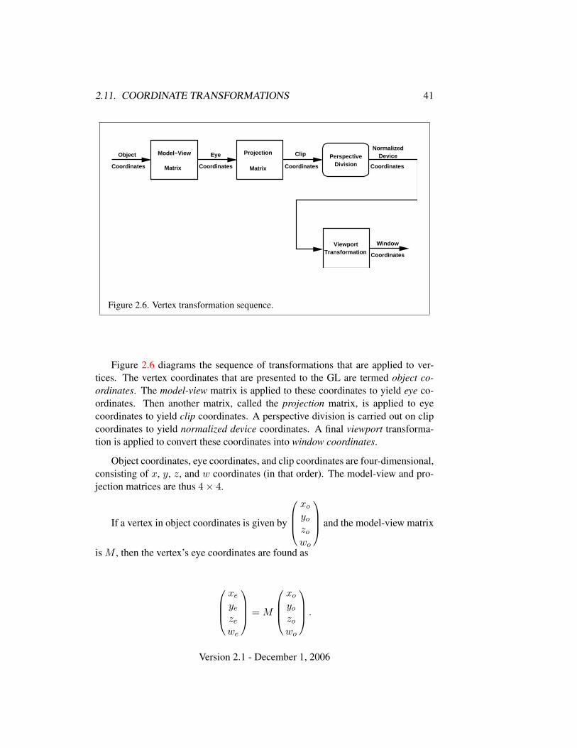
2.11. COORDINATE TRANSFORMATIONS 41
Object
Coordinates Coordinates
Eye
Coordinates
Window
Coordinates
NormalizedDeviceModel−View
Matrix
PerspectiveDivision
ViewportTransformation
Coordinates
ClipProjection
Matrix
Figure 2.6. Vertex transformation sequence.
Figure 2.6 diagrams the sequence of transformations that are applied to ver-tices. The vertex coordinates that are presented to the GL are termed object co-ordinates. The model-view matrix is applied to these coordinates to yield eye co-ordinates. Then another matrix, called the projection matrix, is applied to eyecoordinates to yield clip coordinates. A perspective division is carried out on clipcoordinates to yield normalized device coordinates. A final viewport transforma-tion is applied to convert these coordinates into window coordinates.
Object coordinates, eye coordinates, and clip coordinates are four-dimensional,consisting of x, y, z, and w coordinates (in that order). The model-view and pro-jection matrices are thus 4× 4.
If a vertex in object coordinates is given by
xo
yo
zo
wo
and the model-view matrix
is M , then the vertex’s eye coordinates are found as
xe
ye
ze
we
= M
xo
yo
zo
wo
.
Version 2.1 - December 1, 2006
42 CHAPTER 2. OPENGL OPERATION
Similarly, if P is the projection matrix, then the vertex’s clip coordinates arexc
yc
zc
wc
= P
xe
ye
ze
we
.
The vertex’s normalized device coordinates are thenxd
yd
zd
=
xc/wc
yc/wc
zc/wc
.
2.11.1 Controlling the Viewport
The viewport transformation is determined by the viewport’s width and height inpixels, px and py, respectively, and its center (ox, oy) (also in pixels). The vertex’s
window coordinates,
xw
yw
zw
, are given by
xw
yw
zw
=
(px/2)xd + ox
(py/2)yd + oy
[(f − n)/2]zd + (n + f)/2
.
The factor and offset applied to zd encoded by n and f are set using
void DepthRange( clampd n, clampd f );
Each of n and f are clamped to lie within [0, 1], as are all arguments of type clampdor clampf. zw is taken to be represented in fixed-point with at least as many bitsas there are in the depth buffer of the framebuffer. We assume that the fixed-pointrepresentation used represents each value k/(2m − 1), where k ∈ {0, 1, . . . , 2m −1}, as k (e.g. 1.0 is represented in binary as a string of all ones).
Viewport transformation parameters are specified using
void Viewport( int x, int y, sizei w, sizei h );
where x and y give the x and y window coordinates of the viewport’s lower leftcorner and w and h give the viewport’s width and height, respectively. The viewportparameters shown in the above equations are found from these values as ox =x + w/2 and oy = y + h/2; px = w, py = h.
Version 2.1 - December 1, 2006
2.11. COORDINATE TRANSFORMATIONS 43
Viewport width and height are clamped to implementation-dependent maxi-mums when specified. The maximum width and height may be found by issuingan appropriate Get command (see chapter 6). The maximum viewport dimensionsmust be greater than or equal to the visible dimensions of the display being ren-dered to. INVALID VALUE is generated if either w or h is negative.
The state required to implement the viewport transformation is four integersand two clamped floating-point values. In the initial state, w and h are set to thewidth and height, respectively, of the window into which the GL is to do its ren-dering. ox and oy are set to w/2 and h/2, respectively. n and f are set to 0.0 and1.0, respectively.
2.11.2 Matrices
The projection matrix and model-view matrix are set and modified with a varietyof commands. The affected matrix is determined by the current matrix mode. Thecurrent matrix mode is set with
void MatrixMode( enum mode );
which takes one of the pre-defined constants TEXTURE, MODELVIEW, COLOR, orPROJECTION as the argument value. TEXTURE is described later in section 2.11.2,and COLOR is described in section 3.6.3. If the current matrix mode is MODELVIEW,then matrix operations apply to the model-view matrix; if PROJECTION, then theyapply to the projection matrix.
The two basic commands for affecting the current matrix are
void LoadMatrix{fd}( T m[16] );void MultMatrix{fd}( T m[16] );
LoadMatrix takes a pointer to a 4× 4 matrix stored in column-major order as 16consecutive floating-point values, i.e. as
a1 a5 a9 a13
a2 a6 a10 a14
a3 a7 a11 a15
a4 a8 a12 a16
.
(This differs from the standard row-major C ordering for matrix elements. If thestandard ordering is used, all of the subsequent transformation equations are trans-posed, and the columns representing vectors become rows.)
The specified matrix replaces the current matrix with the one pointed to. Mult-Matrix takes the same type argument as LoadMatrix, but multiplies the current
Version 2.1 - December 1, 2006
44 CHAPTER 2. OPENGL OPERATION
matrix by the one pointed to and replaces the current matrix with the product. If Cis the current matrix and M is the matrix pointed to by MultMatrix’s argument,then the resulting current matrix, C ′, is
C ′ = C ·M.
The commands
void LoadTransposeMatrix{fd}( T m[16] );void MultTransposeMatrix{fd}( T m[16] );
take pointers to 4×4 matrices stored in row-major order as 16 consecutive floating-point values, i.e. as
a1 a2 a3 a4
a5 a6 a7 a8
a9 a10 a11 a12
a13 a14 a15 a16
.
The effect of
LoadTransposeMatrix[fd](m);
is the same as the effect of
LoadMatrix[fd](mT);
The effect of
MultTransposeMatrix[fd](m);
is the same as the effect of
MultMatrix[fd](mT);
The command
void LoadIdentity( void );
effectively calls LoadMatrix with the identity matrix:1 0 0 00 1 0 00 0 1 00 0 0 1
.
There are a variety of other commands that manipulate matrices. Rotate,Translate, Scale, Frustum, and Ortho manipulate the current matrix. Each com-putes a matrix and then invokes MultMatrix with this matrix. In the case of
Version 2.1 - December 1, 2006
2.11. COORDINATE TRANSFORMATIONS 45
void Rotate{fd}( T θ, T x, T y, T z );
θ gives an angle of rotation in degrees; the coordinates of a vector v are given byv = (x y z)T . The computed matrix is a counter-clockwise rotation about the linethrough the origin with the specified axis when that axis is pointing up (i.e. theright-hand rule determines the sense of the rotation angle). The matrix is thus
0R 0
00 0 0 1
.
Let u = v/||v|| = (x′ y′ z′ )T . If
S =
0 −z′ y′
z′ 0 −x′
−y′ x′ 0
then
R = uuT + cos θ(I − uuT ) + sin θS.
The arguments to
void Translate{fd}( T x, T y, T z );
give the coordinates of a translation vector as (x y z)T . The resulting matrix is atranslation by the specified vector:
1 0 0 x0 1 0 y0 0 1 z0 0 0 1
.
void Scale{fd}( T x, T y, T z );
produces a general scaling along the x-, y-, and z- axes. The corresponding matrixis
x 0 0 00 y 0 00 0 z 00 0 0 1
.
For
Version 2.1 - December 1, 2006
46 CHAPTER 2. OPENGL OPERATION
void Frustum( double l, double r, double b, double t,double n, double f );
the coordinates (l b − n)T and (r t − n)T specify the points on the near clippingplane that are mapped to the lower left and upper right corners of the window,respectively (assuming that the eye is located at (0 0 0)T ). f gives the distancefrom the eye to the far clipping plane. If either n or f is less than or equal to zero,l is equal to r, b is equal to t, or n is equal to f , the error INVALID VALUE results.The corresponding matrix is
2nr−l 0 r+l
r−l 00 2n
t−bt+bt−b 0
0 0 −f+nf−n − 2fn
f−n0 0 −1 0
.
void Ortho( double l, double r, double b, double t,double n, double f );
describes a matrix that produces parallel projection. (l b − n)T and (r t − n)T
specify the points on the near clipping plane that are mapped to the lower left andupper right corners of the window, respectively. f gives the distance from the eyeto the far clipping plane. If l is equal to r, b is equal to t, or n is equal to f , theerror INVALID VALUE results. The corresponding matrix is
2r−l 0 0 − r+l
r−l
0 2t−b 0 − t+b
t−b
0 0 − 2f−n −f+n
f−n0 0 0 1
.
For each texture coordinate set, a 4× 4 matrix is applied to the correspondingtexture coordinates. This matrix is applied as
m1 m5 m9 m13
m2 m6 m10 m14
m3 m7 m11 m15
m4 m8 m12 m16
strq
,
where the left matrix is the current texture matrix. The matrix is applied to thecoordinates resulting from texture coordinate generation (which may simply be thecurrent texture coordinates), and the resulting transformed coordinates become thetexture coordinates associated with a vertex. Setting the matrix mode to TEXTURE
causes the already described matrix operations to apply to the texture matrix.The command
Version 2.1 - December 1, 2006
2.11. COORDINATE TRANSFORMATIONS 47
void ActiveTexture( enum texture );
specifies the active texture unit selector, ACTIVE TEXTURE. Each texture unit con-tains up to two distinct sub-units: a texture coordinate processing unit (consistingof a texture matrix stack and texture coordinate generation state) and a textureimage unit (consisting of all the texture state defined in section 3.8). In implemen-tations with a different number of supported texture coordinate sets and textureimage units, some texture units may consist of only one of the two sub-units.
The active texture unit selector specifies the texture coordinate set accessedby commands involving texture coordinate processing. Such commands includethose accessing the current matrix stack (if MATRIX MODE is TEXTURE), TexEnvcommands controlling point sprite coordinate replacement (see section 3.3), Tex-Gen (section 2.11.4), Enable/Disable (if any texture coordinate generation enumis selected), as well as queries of the current texture coordinates and current rastertexture coordinates. If the texture coordinate set number corresponding to the cur-rent value of ACTIVE TEXTURE is greater than or equal to the implementation-dependent constant MAX TEXTURE COORDS, the error INVALID OPERATION isgenerated by any such command.
The active texture unit selector also selects the texture image unit accessedby commands involving texture image processing (section 3.8). Such commandsinclude all variants of TexEnv (except for those controlling point sprite coordi-nate replacement), TexParameter, and TexImage commands, BindTexture, En-able/Disable for any texture target (e.g., TEXTURE 2D), and queries of all suchstate. If the texture image unit number corresponding to the current value ofACTIVE TEXTURE is greater than or equal to the implementation-dependent con-stant MAX COMBINED TEXTURE IMAGE UNITS, the error INVALID OPERATION isgenerated by any such command.
ActiveTexture generates the error INVALID ENUM if an invalid texture is spec-ified. texture is a symbolic constant of the form TEXTUREi, indicating that tex-ture unit i is to be modified. The constants obey TEXTUREi = TEXTURE0 + i (iis in the range 0 to k − 1, where k is the larger of MAX TEXTURE COORDS andMAX COMBINED TEXTURE IMAGE UNITS).
For backwards compatibility, the implementation-dependentconstant MAX TEXTURE UNITS specifies the number of conventional texture unitssupported by the implementation. Its value must be no larger than the minimum ofMAX TEXTURE COORDS and MAX COMBINED TEXTURE IMAGE UNITS.
There is a stack of matrices for each of matrix modes MODELVIEW,PROJECTION, and COLOR, and for each texture unit. For MODELVIEW mode, thestack depth is at least 32 (that is, there is a stack of at least 32 model-view ma-trices). For the other modes, the depth is at least 2. Texture matrix stacks for all
Version 2.1 - December 1, 2006
48 CHAPTER 2. OPENGL OPERATION
texture units have the same depth. The current matrix in any mode is the matrix onthe top of the stack for that mode.
void PushMatrix( void );
pushes the stack down by one, duplicating the current matrix in both the top of thestack and the entry below it.
void PopMatrix( void );
pops the top entry off of the stack, replacing the current matrix with the matrixthat was the second entry in the stack. The pushing or popping takes place on thestack corresponding to the current matrix mode. Popping a matrix off a stack withonly one entry generates the error STACK UNDERFLOW; pushing a matrix onto a fullstack generates STACK OVERFLOW.
When the current matrix mode is TEXTURE, the texture matrix stack of theactive texture unit is pushed or popped.
The state required to implement transformations consists of an integer for theactive texture unit selector, a four-valued integer indicating the current matrixmode, one stack of at least two 4 × 4 matrices for each of COLOR, PROJECTION,and each texture coordinate set, TEXTURE; and a stack of at least 32 4 × 4 matri-ces for MODELVIEW. Each matrix stack has an associated stack pointer. Initially,there is only one matrix on each stack, and all matrices are set to the identity.The initial active texture unit selector is TEXTURE0, and the initial matrix mode isMODELVIEW.
2.11.3 Normal Transformation
Finally, we consider how the model-view matrix and transformation state affectnormals. Before use in lighting, normals are transformed to eye coordinates by amatrix derived from the model-view matrix. Rescaling and normalization opera-tions are performed on the transformed normals to make them unit length prior touse in lighting. Rescaling and normalization are controlled by
void Enable( enum target );
and
void Disable( enum target );
Version 2.1 - December 1, 2006
2.11. COORDINATE TRANSFORMATIONS 49
with target equal to RESCALE NORMAL or NORMALIZE. This requires two bits ofstate. The initial state is for normals not to be rescaled or normalized.
If the model-view matrix is M , then the normal is transformed to eye coordi-nates by:
( nx′ ny
′ nz′ q′ ) = ( nx ny nz q ) ·M−1
where, if
xyzw
are the associated vertex coordinates, then
q =
0, w = 0,
−(nx ny nz )
xyz
w , w 6= 0
(2.1)
Implementations may choose instead to transform ( nx ny nz ) to eye coor-dinates using
( nx′ ny
′ nz′ ) = ( nx ny nz ) ·Mu
−1
where Mu is the upper leftmost 3x3 matrix taken from M .Rescale multiplies the transformed normals by a scale factor
( nx′′ ny
′′ nz′′ ) = f ( nx
′ ny′ nz
′ )
If rescaling is disabled, then f = 1. If rescaling is enabled, then f is computedas (mij denotes the matrix element in row i and column j of M−1, numbering thetopmost row of the matrix as row 1 and the leftmost column as column 1)
f =1√
m312 + m32
2 + m332
Note that if the normals sent to GL were unit length and the model-view matrixuniformly scales space, then rescale makes the transformed normals unit length.
Alternatively, an implementation may choose f as
f =1√
nx′2 + ny
′2 + nz′2
recomputing f for each normal. This makes all non-zero length normals unit lengthregardless of their input length and the nature of the model-view matrix.
Version 2.1 - December 1, 2006
50 CHAPTER 2. OPENGL OPERATION
After rescaling, the final transformed normal used in lighting, nf , is computedas
nf = m ( nx′′ ny
′′ nz′′ )
If normalization is disabled, then m = 1. Otherwise
m =1√
nx′′2 + ny
′′2 + nz′′2
Because we specify neither the floating-point format nor the means for matrixinversion, we cannot specify behavior in the case of a poorly-conditioned (nearlysingular) model-view matrix M . In case of an exactly singular matrix, the trans-formed normal is undefined. If the GL implementation determines that the model-view matrix is uninvertible, then the entries in the inverted matrix are arbitrary. Inany case, neither normal transformation nor use of the transformed normal maylead to GL interruption or termination.
2.11.4 Generating Texture Coordinates
Texture coordinates associated with a vertex may either be taken from the currenttexture coordinates or generated according to a function dependent on vertex coor-dinates. The command
void TexGen{ifd}( enum coord, enum pname, T param );void TexGen{ifd}v( enum coord, enum pname, T params );
controls texture coordinate generation. coord must be one of the constants S, T,R, or Q, indicating that the pertinent coordinate is the s, t, r, or q coordinate, re-spectively. In the first form of the command, param is a symbolic constant speci-fying a single-valued texture generation parameter; in the second form, params isa pointer to an array of values that specify texture generation parameters. pnamemust be one of the three symbolic constants TEXTURE GEN MODE, OBJECT PLANE,or EYE PLANE. If pname is TEXTURE GEN MODE, then either params points toor param is an integer that is one of the symbolic constants OBJECT LINEAR,EYE LINEAR, SPHERE MAP, REFLECTION MAP, or NORMAL MAP.
If TEXTURE GEN MODE indicates OBJECT LINEAR, then the generation func-tion for the coordinate indicated by coord is
g = p1xo + p2yo + p3zo + p4wo.
xo, yo, zo, and wo are the object coordinates of the vertex. p1, . . . , p4 are specifiedby calling TexGen with pname set to OBJECT PLANE in which case params points
Version 2.1 - December 1, 2006
2.11. COORDINATE TRANSFORMATIONS 51
to an array containing p1, . . . , p4. There is a distinct group of plane equation co-efficients for each texture coordinate; coord indicates the coordinate to which thespecified coefficients pertain.
If TEXTURE GEN MODE indicates EYE LINEAR, then the function is
g = p′1xe + p′2ye + p′3ze + p′4we
where( p′1 p′2 p′3 p′4 ) = ( p1 p2 p3 p4 ) M−1
xe, ye, ze, and we are the eye coordinates of the vertex. p1, . . . , p4 are set bycalling TexGen with pname set to EYE PLANE in correspondence with setting thecoefficients in the OBJECT PLANE case. M is the model-view matrix in effectwhen p1, . . . , p4 are specified. Computed texture coordinates may be inaccurate orundefined if M is poorly conditioned or singular.
When used with a suitably constructed texture image, calling TexGen withTEXTURE GEN MODE indicating SPHERE MAP can simulate the reflected image ofa spherical environment on a polygon. SPHERE MAP texture coordinates are gen-erated as follows. Denote the unit vector pointing from the origin to the vertex(in eye coordinates) by u. Denote the current normal, after transformation to eyecoordinates, by nf . Let r = ( rx ry rz )T , the reflection vector, be given by
r = u− 2nfT (nfu) ,
and let m = 2√
r2x + r2
y + (rz + 1)2. Then the value assigned to an s coordinate(the first TexGen argument value is S) is s = rx/m + 1
2 ; the value assigned to a tcoordinate is t = ry/m + 1
2 . Calling TexGen with a coord of either R or Q whenpname indicates SPHERE MAP generates the error INVALID ENUM.
If TEXTURE GEN MODE indicates REFLECTION MAP, compute the reflectionvector r as described for the SPHERE MAP mode. Then the value assigned to ans coordinate is s = rx; the value assigned to a t coordinate is t = ry; and the valueassigned to an r coordinate is r = rz . Calling TexGen with a coord of Q whenpname indicates REFLECTION MAP generates the error INVALID ENUM.
If TEXTURE GEN MODE indicates NORMAL MAP, compute the normal vector nf
as described in section 2.11.3. Then the value assigned to an s coordinate is s =nf x; the value assigned to a t coordinate is t = nf y; and the value assigned to anr coordinate is r = nf z (the values nf x, nf y, and nf z are the components of nf .)Calling TexGen with a coord of Q when pname indicates NORMAL MAP generatesthe error INVALID ENUM.
A texture coordinate generation function is enabled or disabled using En-able and Disable with an argument of TEXTURE GEN S, TEXTURE GEN T,
Version 2.1 - December 1, 2006

52 CHAPTER 2. OPENGL OPERATION
TEXTURE GEN R, or TEXTURE GEN Q (each indicates the corresponding texture co-ordinate). When enabled, the specified texture coordinate is computed accordingto the current EYE LINEAR, OBJECT LINEAR or SPHERE MAP specification, de-pending on the current setting of TEXTURE GEN MODE for that coordinate. Whendisabled, subsequent vertices will take the indicated texture coordinate from thecurrent texture coordinates.
The state required for texture coordinate generation for each texture unit com-prises a five-valued integer for each coordinate indicating coordinate generationmode, and a bit for each coordinate to indicate whether texture coordinate genera-tion is enabled or disabled. In addition, four coefficients are required for the fourcoordinates for each of EYE LINEAR and OBJECT LINEAR. The initial state has thetexture generation function disabled for all texture coordinates. The initial valuesof pi for s are all 0 except p1 which is one; for t all the pi are zero except p2, whichis 1. The values of pi for r and q are all 0. These values of pi apply for both theEYE LINEAR and OBJECT LINEAR versions. Initially all texture generation modesare EYE LINEAR.
2.12 Clipping
Primitives are clipped to the clip volume. In clip coordinates, the view volume isdefined by
−wc ≤ xc ≤ wc
−wc ≤ yc ≤ wc
−wc ≤ zc ≤ wc.
This view volume may be further restricted by as many as n client-defined clipplanes to generate the clip volume. (n is an implementation dependent maximumthat must be at least 6.) Each client-defined plane specifies a half-space. The clipvolume is the intersection of all such half-spaces with the view volume (if there noclient-defined clip planes are enabled, the clip volume is the view volume).
A client-defined clip plane is specified with
void ClipPlane( enum p, double eqn[4] );
The value of the first argument, p, is a symbolic constant, CLIP PLANEi, where i isan integer between 0 and n− 1, indicating one of n client-defined clip planes. eqnis an array of four double-precision floating-point values. These are the coefficientsof a plane equation in object coordinates: p1, p2, p3, and p4 (in that order). Theinverse of the current model-view matrix is applied to these coefficients, at the timethey are specified, yielding
( p′1 p′2 p′3 p′4 ) = ( p1 p2 p3 p4 ) M−1
Version 2.1 - December 1, 2006
2.12. CLIPPING 53
(where M is the current model-view matrix; the resulting plane equation is unde-fined if M is singular and may be inaccurate if M is poorly-conditioned) to obtainthe plane equation coefficients in eye coordinates. All points with eye coordinates( xe ye ze we )T that satisfy
( p′1 p′2 p′3 p′4 )
xe
ye
ze
we
≥ 0
lie in the half-space defined by the plane; points that do not satisfy this conditiondo not lie in the half-space.
When a vertex shader is active, the vector ( xe ye ze we )T is no longercomputed. Instead, the value of the gl ClipVertex built-in variable is used in itsplace. If gl ClipVertex is not written by the vertex shader, its value is undefined,which implies that the results of clipping to any client-defined clip planes are alsoundefined. The user must ensure that the clip vertex and client-defined clip planesare defined in the same coordinate space.
Client-defined clip planes are enabled with the generic Enable command anddisabled with the Disable command. The value of the argument to either com-mand is CLIP PLANEi where i is an integer between 0 and n; specifying a valueof i enables or disables the plane equation with index i. The constants obeyCLIP PLANEi = CLIP PLANE0 + i.
If the primitive under consideration is a point, then clipping passes it un-changed if it lies within the clip volume; otherwise, it is discarded. If the prim-itive is a line segment, then clipping does nothing to it if it lies entirely within theclip volume and discards it if it lies entirely outside the volume. If part of the linesegment lies in the volume and part lies outside, then the line segment is clippedand new vertex coordinates are computed for one or both vertices. A clipped linesegment endpoint lies on both the original line segment and the boundary of theclip volume.
This clipping produces a value, 0 ≤ t ≤ 1, for each clipped vertex. If thecoordinates of a clipped vertex are P and the original vertices’ coordinates are P1
and P2, then t is given by
P = tP1 + (1− t)P2.
The value of t is used in color, secondary color, texture coordinate, and fog coor-dinate clipping (section 2.14.8).
If the primitive is a polygon, then it is passed if every one of its edges liesentirely inside the clip volume and either clipped or discarded otherwise. Polygon
Version 2.1 - December 1, 2006
54 CHAPTER 2. OPENGL OPERATION
clipping may cause polygon edges to be clipped, but because polygon connectivitymust be maintained, these clipped edges are connected by new edges that lie alongthe clip volume’s boundary. Thus, clipping may require the introduction of newvertices into a polygon. Edge flags are associated with these vertices so that edgesintroduced by clipping are flagged as boundary (edge flag TRUE), and so that orig-inal edges of the polygon that become cut off at these vertices retain their originalflags.
If it happens that a polygon intersects an edge of the clip volume’s boundary,then the clipped polygon must include a point on this boundary edge. This pointmust lie in the intersection of the boundary edge and the convex hull of the verticesof the original polygon. We impose this requirement because the polygon may notbe exactly planar.
Primitives rendered with clip planes must satisfy a complementarity crite-rion. Suppose a single clip plane with coefficients ( p′1 p′2 p′3 p′4 ) (or a num-ber of similarly specified clip planes) is enabled and a series of primitives aredrawn. Next, suppose that the original clip plane is respecified with coefficients(−p′1 −p′2 −p′3 −p′4 ) (and correspondingly for any other clip planes) andthe primitives are drawn again (and the GL is otherwise in the same state). In thiscase, primitives must not be missing any pixels, nor may any pixels be drawn twicein regions where those primitives are cut by the clip planes.
The state required for clipping is at least 6 sets of plane equations (each consist-ing of four double-precision floating-point coefficients) and at least 6 correspond-ing bits indicating which of these client-defined plane equations are enabled. In theinitial state, all client-defined plane equation coefficients are zero and all planes aredisabled.
2.13 Current Raster Position
The current raster position is used by commands that directly affect pixels in theframebuffer. These commands, which bypass vertex transformation and primitiveassembly, are described in the next chapter. The current raster position, however,shares some of the characteristics of a vertex.
The current raster position is set using one of the commands
void RasterPos{234}{sifd}( T coords );void RasterPos{234}{sifd}v( T coords );
RasterPos4 takes four values indicating x, y, z, and w. RasterPos3 (or Raster-Pos2) is analogous, but sets only x, y, and z with w implicitly set to 1 (or only xand y with z implicitly set to 0 and w implicitly set to 1).
Version 2.1 - December 1, 2006
2.13. CURRENT RASTER POSITION 55
Gets of CURRENT RASTER TEXTURE COORDS are affected by the setting of thestate ACTIVE TEXTURE.
The coordinates are treated as if they were specified in a Vertex command. Ifa vertex shader is active, this vertex shader is executed using the x, y, z, and wcoordinates as the object coordinates of the vertex. Otherwise, the x, y, z, andw coordinates are transformed by the current model-view and projection matri-ces. These coordinates, along with current values, are used to generate primaryand secondary colors and texture coordinates just as is done for a vertex. The col-ors and texture coordinates so produced replace the colors and texture coordinatesstored in the current raster position’s associated data. If a vertex shader is activethen the current raster distance is set to the value of the shader built in varyinggl FogFragCoord. Otherwise, if the value of the fog source (see section 3.10)is FOG COORD, then the current raster distance is set to the value of the currentfog coordinate. Otherwise, the current raster distance is set to the distance fromthe origin of the eye coordinate system to the vertex as transformed by only thecurrent model-view matrix. This distance may be approximated as discussed insection 3.10.
Since vertex shaders may be executed when the raster position is set, any at-tributes not written by the shader will result in undefined state in the current rasterposition. Vertex shaders should output all varying variables that would be usedwhen rasterizing pixel primitives using the current raster position.
The transformed coordinates are passed to clipping as if they represented apoint. If the “point” is not culled, then the projection to window coordinates iscomputed (section 2.11) and saved as the current raster position, and the validbit is set. If the “point” is culled, the current raster position and its associateddata become indeterminate and the valid bit is cleared. Figure 2.7 summarizes thebehavior of the current raster position.
Alternately, the current raster position may be set by one of the WindowPoscommands:
void WindowPos{23}{ifds}( T coords );void WindowPos{23}{ifds}v( const T coords );
WindowPos3 takes three values indicating x, y and z, while WindowPos2takes two values indicating x and y with z implicitly set to 0. The current rasterposition, (xw, yw, zw, wc), is defined by:
xw = x
yw = y
Version 2.1 - December 1, 2006
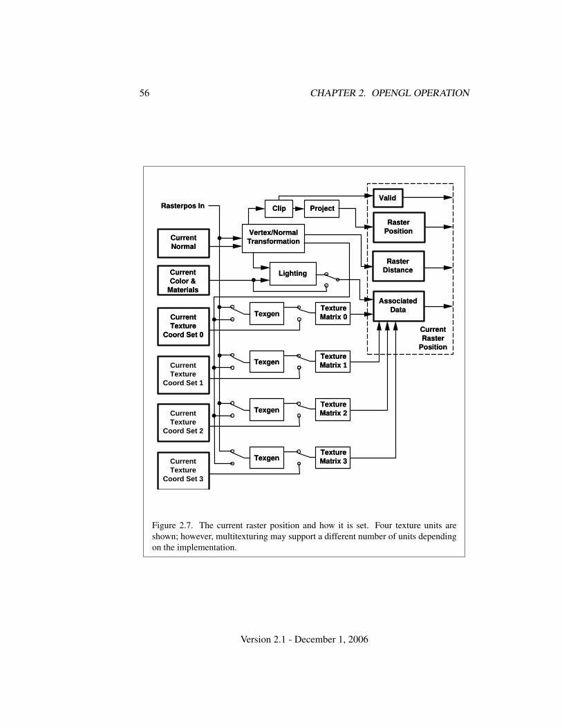
56 CHAPTER 2. OPENGL OPERATION
Rasterpos In
CurrentNormal
Lighting
Vertex/NormalTransformation
Clip Project
CurrentRaster
Position
Valid
RasterPosition
RasterDistance
AssociatedData
CurrentColor &
Materials
TextureMatrix 0Current
TextureCoord Set 0
Texgen
TextureMatrix 3Current
TextureCoord Set 3
Texgen
TextureMatrix 2Current
TextureCoord Set 2
Texgen
TextureMatrix 1Current
TextureCoord Set 1
Texgen
Figure 2.7. The current raster position and how it is set. Four texture units areshown; however, multitexturing may support a different number of units dependingon the implementation.
Version 2.1 - December 1, 2006

2.14. COLORS AND COLORING 57
zw =
n, z ≤ 0f, z ≥ 1n + z(f − n), otherwise
wc = 1
where n and f are the values passed to DepthRange (see section 2.11.1).Lighting, texture coordinate generation and transformation, and clipping are
not performed by the WindowPos functions. Instead, in RGBA mode, the currentraster color and secondary color are obtained by clamping each component of thecurrent color and secondary color, respectively, to [0, 1]. In color index mode, thecurrent raster color index is set to the current color index. The current raster texturecoordinates are set to the current texture coordinates, and the valid bit is set.
If the value of the fog source is FOG COORD SRC, then the current raster dis-tance is set to the value of the current fog coordinate. Otherwise, the raster distanceis set to 0.
The current raster position requires six single-precision floating-point valuesfor its xw, yw, and zw window coordinates, its wc clip coordinate, its raster distance(used as the fog coordinate in raster processing), a single valid bit, four floating-point values to store the current RGBA color, four floating-point values to store thecurrent RGBA secondary color, one floating-point value to store the current colorindex, and 4 floating-point values for texture coordinates for each texture unit. Inthe initial state, the coordinates and texture coordinates are all (0, 0, 0, 1), the eyecoordinate distance is 0, the fog coordinate is 0, the valid bit is set, the associatedRGBA color is (1, 1, 1, 1), the associated RGBA secondary color is (0, 0, 0, 1), andthe associated color index color is 1. In RGBA mode, the associated color indexalways has its initial value; in color index mode, the RGBA color and secondarycolor always maintain their initial values.
2.14 Colors and Coloring
Figures 2.8 and 2.9 diagram the processing of RGBA colors and color indices be-fore rasterization. Incoming colors arrive in one of several formats. Table 2.9 sum-marizes the conversions that take place on R, G, B, and A components dependingon which version of the Color command was invoked to specify the components.As a result of limited precision, some converted values will not be representedexactly. In color index mode, a single-valued color index is not mapped.
Version 2.1 - December 1, 2006
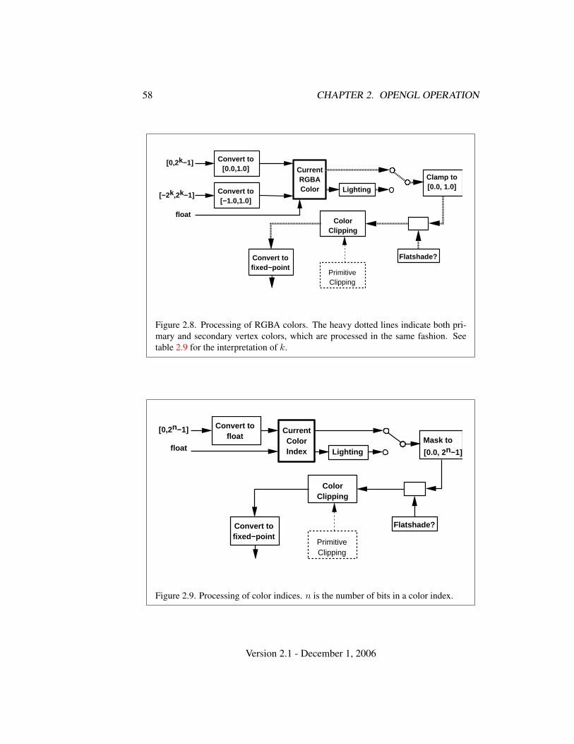
58 CHAPTER 2. OPENGL OPERATION
[0,2k−1]
float
Convert to[0.0,1.0]
[−2k,2k−1] Convert to[−1.0,1.0]
CurrentRGBAColor Lighting
Clamp to[0.0, 1.0]
Flatshade?
PrimitiveClipping
ColorClipping
Convert tofixed−point
Figure 2.8. Processing of RGBA colors. The heavy dotted lines indicate both pri-mary and secondary vertex colors, which are processed in the same fashion. Seetable 2.9 for the interpretation of k.
Convert tofloat
[0,2n−1]
float
CurrentColorIndex Lighting
Mask to
[0.0, 2n−1]
Flatshade?
PrimitiveClipping
ColorClipping
Convert tofixed−point
Figure 2.9. Processing of color indices. n is the number of bits in a color index.
Version 2.1 - December 1, 2006
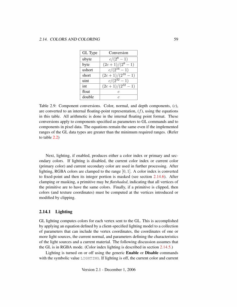
2.14. COLORS AND COLORING 59
GL Type Conversionubyte c/(28 − 1)byte (2c + 1)/(28 − 1)ushort c/(216 − 1)short (2c + 1)/(216 − 1)uint c/(232 − 1)int (2c + 1)/(232 − 1)float c
double c
Table 2.9: Component conversions. Color, normal, and depth components, (c),are converted to an internal floating-point representation, (f ), using the equationsin this table. All arithmetic is done in the internal floating point format. Theseconversions apply to components specified as parameters to GL commands and tocomponents in pixel data. The equations remain the same even if the implementedranges of the GL data types are greater than the minimum required ranges. (Referto table 2.2)
Next, lighting, if enabled, produces either a color index or primary and sec-ondary colors. If lighting is disabled, the current color index or current color(primary color) and current secondary color are used in further processing. Afterlighting, RGBA colors are clamped to the range [0, 1]. A color index is convertedto fixed-point and then its integer portion is masked (see section 2.14.6). Afterclamping or masking, a primitive may be flatshaded, indicating that all vertices ofthe primitive are to have the same colors. Finally, if a primitive is clipped, thencolors (and texture coordinates) must be computed at the vertices introduced ormodified by clipping.
2.14.1 Lighting
GL lighting computes colors for each vertex sent to the GL. This is accomplishedby applying an equation defined by a client-specified lighting model to a collectionof parameters that can include the vertex coordinates, the coordinates of one ormore light sources, the current normal, and parameters defining the characteristicsof the light sources and a current material. The following discussion assumes thatthe GL is in RGBA mode. (Color index lighting is described in section 2.14.5.)
Lighting is turned on or off using the generic Enable or Disable commandswith the symbolic value LIGHTING. If lighting is off, the current color and current
Version 2.1 - December 1, 2006
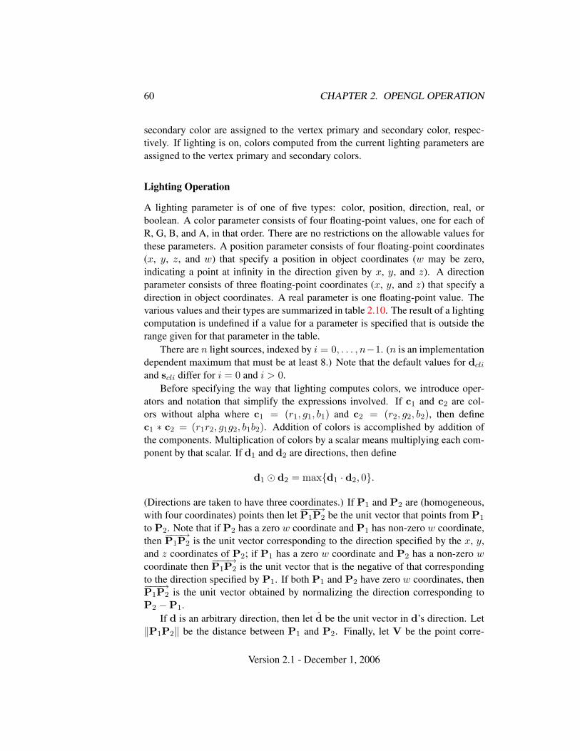
60 CHAPTER 2. OPENGL OPERATION
secondary color are assigned to the vertex primary and secondary color, respec-tively. If lighting is on, colors computed from the current lighting parameters areassigned to the vertex primary and secondary colors.
Lighting Operation
A lighting parameter is of one of five types: color, position, direction, real, orboolean. A color parameter consists of four floating-point values, one for each ofR, G, B, and A, in that order. There are no restrictions on the allowable values forthese parameters. A position parameter consists of four floating-point coordinates(x, y, z, and w) that specify a position in object coordinates (w may be zero,indicating a point at infinity in the direction given by x, y, and z). A directionparameter consists of three floating-point coordinates (x, y, and z) that specify adirection in object coordinates. A real parameter is one floating-point value. Thevarious values and their types are summarized in table 2.10. The result of a lightingcomputation is undefined if a value for a parameter is specified that is outside therange given for that parameter in the table.
There are n light sources, indexed by i = 0, . . . , n−1. (n is an implementationdependent maximum that must be at least 8.) Note that the default values for dcli
and scli differ for i = 0 and i > 0.Before specifying the way that lighting computes colors, we introduce oper-
ators and notation that simplify the expressions involved. If c1 and c2 are col-ors without alpha where c1 = (r1, g1, b1) and c2 = (r2, g2, b2), then definec1 ∗ c2 = (r1r2, g1g2, b1b2). Addition of colors is accomplished by addition ofthe components. Multiplication of colors by a scalar means multiplying each com-ponent by that scalar. If d1 and d2 are directions, then define
d1 � d2 = max{d1 · d2, 0}.
(Directions are taken to have three coordinates.) If P1 and P2 are (homogeneous,with four coordinates) points then let −−−→P1P2 be the unit vector that points from P1
to P2. Note that if P2 has a zero w coordinate and P1 has non-zero w coordinate,then −−−→P1P2 is the unit vector corresponding to the direction specified by the x, y,and z coordinates of P2; if P1 has a zero w coordinate and P2 has a non-zero wcoordinate then −−−→P1P2 is the unit vector that is the negative of that correspondingto the direction specified by P1. If both P1 and P2 have zero w coordinates, then−−−→P1P2 is the unit vector obtained by normalizing the direction corresponding toP2 −P1.
If d is an arbitrary direction, then let d be the unit vector in d’s direction. Let‖P1P2‖ be the distance between P1 and P2. Finally, let V be the point corre-
Version 2.1 - December 1, 2006
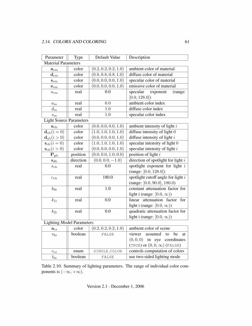
2.14. COLORS AND COLORING 61
Parameter Type Default Value DescriptionMaterial Parameters
acm color (0.2, 0.2, 0.2, 1.0) ambient color of materialdcm color (0.8, 0.8, 0.8, 1.0) diffuse color of materialscm color (0.0, 0.0, 0.0, 1.0) specular color of materialecm color (0.0, 0.0, 0.0, 1.0) emissive color of materialsrm real 0.0 specular exponent (range:
[0.0, 128.0])am real 0.0 ambient color indexdm real 1.0 diffuse color indexsm real 1.0 specular color index
Light Source Parametersacli color (0.0, 0.0, 0.0, 1.0) ambient intensity of light i
dcli(i = 0) color (1.0, 1.0, 1.0, 1.0) diffuse intensity of light 0dcli(i > 0) color (0.0, 0.0, 0.0, 1.0) diffuse intensity of light i
scli(i = 0) color (1.0, 1.0, 1.0, 1.0) specular intensity of light 0scli(i > 0) color (0.0, 0.0, 0.0, 1.0) specular intensity of light i
Ppli position (0.0, 0.0, 1.0, 0.0) position of light i
sdli direction (0.0, 0.0,−1.0) direction of spotlight for light i
srli real 0.0 spotlight exponent for light i(range: [0.0, 128.0])
crli real 180.0 spotlight cutoff angle for light i(range: [0.0, 90.0], 180.0)
k0i real 1.0 constant attenuation factor forlight i (range: [0.0,∞))
k1i real 0.0 linear attenuation factor forlight i (range: [0.0,∞))
k2i real 0.0 quadratic attenuation factor forlight i (range: [0.0,∞))
Lighting Model Parametersacs color (0.2, 0.2, 0.2, 1.0) ambient color of scenevbs boolean FALSE viewer assumed to be at
(0, 0, 0) in eye coordinates(TRUE) or (0, 0,∞) (FALSE)
ces enum SINGLE COLOR controls computation of colorstbs boolean FALSE use two-sided lighting mode
Table 2.10: Summary of lighting parameters. The range of individual color com-ponents is (−∞,+∞).
Version 2.1 - December 1, 2006
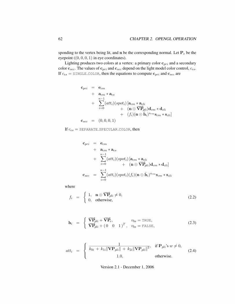
62 CHAPTER 2. OPENGL OPERATION
sponding to the vertex being lit, and n be the corresponding normal. Let Pe be theeyepoint ((0, 0, 0, 1) in eye coordinates).
Lighting produces two colors at a vertex: a primary color cpri and a secondarycolor csec. The values of cpri and csec depend on the light model color control, ces.If ces = SINGLE COLOR, then the equations to compute cpri and csec are
cpri = ecm
+ acm ∗ acs
+n−1∑i=0
(atti)(spoti) [acm ∗ acli
+ (n�−−→VPpli)dcm ∗ dcli
+ (fi)(n� hi)srmscm ∗ scli]csec = (0, 0, 0, 1)
If ces = SEPARATE SPECULAR COLOR, then
cpri = ecm
+ acm ∗ acs
+n−1∑i=0
(atti)(spoti) [acm ∗ acli
+ (n�−−→VPpli)dcm ∗ dcli]
csec =n−1∑i=0
(atti)(spoti)(fi)(n� hi)srmscm ∗ scli
where
fi =
{1, n�−−→VPpli 6= 0,0, otherwise,
(2.2)
hi =
{ −−→VPpli +−−→VPe, vbs = TRUE,−−→VPpli + ( 0 0 1 )T , vbs = FALSE,
(2.3)
atti =
1
k0i + k1i‖VPpli‖ + k2i‖VPpli‖2, if Ppli’s w 6= 0,
1.0, otherwise.(2.4)
Version 2.1 - December 1, 2006
2.14. COLORS AND COLORING 63
spoti =
(−−−→PpliV � sdli)srli , crli 6= 180.0,
−−−→PpliV � sdli ≥ cos(crli),0.0, crli 6= 180.0,
−−−→PpliV � sdli < cos(crli),1.0, crli = 180.0.
(2.5)
All computations are carried out in eye coordinates.The value of A produced by lighting is the alpha value associated with dcm.
A is always associated with the primary color cpri; the alpha component of csec isalways 1.
Results of lighting are undefined if the we coordinate (w in eye coordinates) ofV is zero.
Lighting may operate in two-sided mode (tbs = TRUE), in which a front coloris computed with one set of material parameters (the front material) and a backcolor is computed with a second set of material parameters (the back material).This second computation replaces n with −n. If tbs = FALSE, then the back colorand front color are both assigned the color computed using the front material withn.
Additionally, vertex shaders can operate in two-sided color mode. When a ver-tex shader is active, front and back colors can be computed by the vertex shader andwritten to the gl FrontColor, gl BackColor, gl FrontSecondaryColor
and gl BackSecondaryColor outputs. If VERTEX PROGRAM TWO SIDE is en-abled, the GL chooses between front and back colors, as described below. Oth-erwise, the front color output is always selected. Two-sided color mode isenabled and disabled by calling Enable or Disable with the symbolic valueVERTEX PROGRAM TWO SIDE.
The selection between back and front colors depends on the primitive of whichthe vertex being lit is a part. If the primitive is a point or a line segment, the frontcolor is always selected. If it is a polygon, then the selection is based on the sign ofthe (clipped or unclipped) polygon’s signed area computed in window coordinates.One way to compute this area is
a =12
n−1∑i=0
xiwyi⊕1
w − xi⊕1w yi
w (2.6)
where xiw and yi
w are the x and y window coordinates of the ith vertex of then-vertex polygon (vertices are numbered starting at zero for purposes of this com-putation) and i⊕ 1 is (i + 1) mod n. The interpretation of the sign of this value iscontrolled with
void FrontFace( enum dir );
Setting dir to CCW (corresponding to counter-clockwise orientation of the projectedpolygon in window coordinates) indicates that if a ≤ 0, then the color of each
Version 2.1 - December 1, 2006
64 CHAPTER 2. OPENGL OPERATION
vertex of the polygon becomes the back color computed for that vertex while ifa > 0, then the front color is selected. If dir is CW, then a is replaced by −a in theabove inequalities. This requires one bit of state; initially, it indicates CCW.
2.14.2 Lighting Parameter Specification
Lighting parameters are divided into three categories: material parameters, lightsource parameters, and lighting model parameters (see table 2.10). Sets of lightingparameters are specified with
void Material{if}( enum face, enum pname, T param );void Material{if}v( enum face, enum pname, T params );void Light{if}( enum light, enum pname, T param );void Light{if}v( enum light, enum pname, T params );void LightModel{if}( enum pname, T param );void LightModel{if}v( enum pname, T params );
pname is a symbolic constant indicating which parameter is to be set (see ta-ble 2.11). In the vector versions of the commands, params is a pointer to a groupof values to which to set the indicated parameter. The number of values pointed todepends on the parameter being set. In the non-vector versions, param is a value towhich to set a single-valued parameter. (If param corresponds to a multi-valued pa-rameter, the error INVALID ENUM results.) For the Material command, face mustbe one of FRONT, BACK, or FRONT AND BACK, indicating that the property name ofthe front or back material, or both, respectively, should be set. In the case of Light,light is a symbolic constant of the form LIGHTi, indicating that light i is to havethe specified parameter set. The constants obey LIGHTi = LIGHT0 + i.
Table 2.11 gives, for each of the three parameter groups, the correspondencebetween the pre-defined constant names and their names in the lighting equations,along with the number of values that must be specified with each. Color param-eters specified with Material and Light are converted to floating-point values(if specified as integers) as indicated in table 2.9 for signed integers. The errorINVALID VALUE occurs if a specified lighting parameter lies outside the allowablerange given in table 2.10. (The symbol “∞” indicates the maximum representablemagnitude for the indicated type.)
Material properties can be changed inside a Begin/End pair by calling Ma-terial. However, when a vertex shader is active such property changes are notguaranteed to update material parameters, defined in table 2.11, until the followingEnd command.
Version 2.1 - December 1, 2006
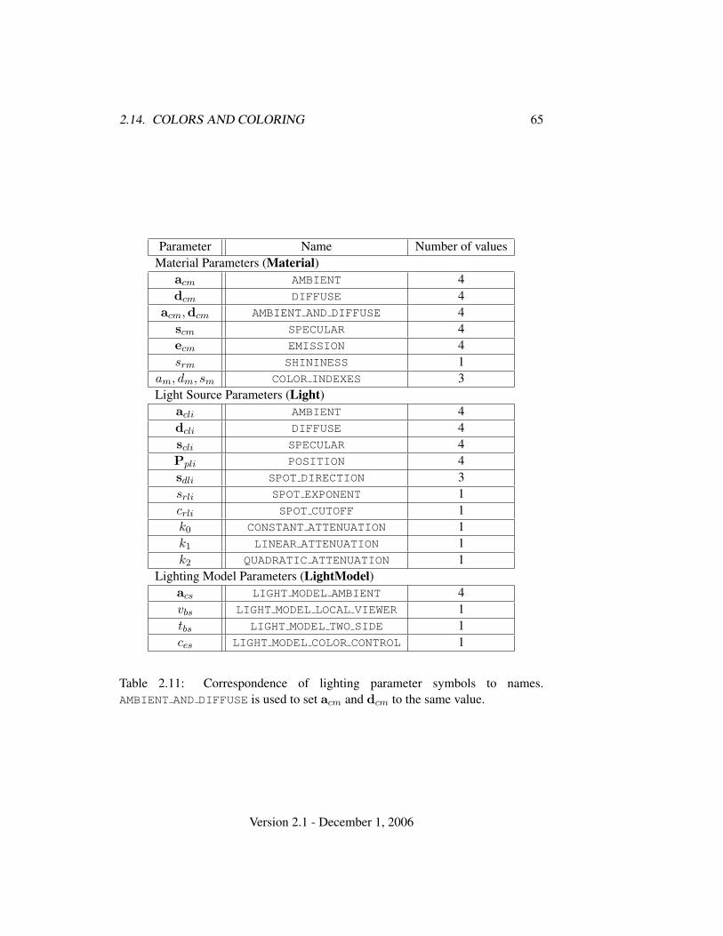
2.14. COLORS AND COLORING 65
Parameter Name Number of valuesMaterial Parameters (Material)
acm AMBIENT 4dcm DIFFUSE 4
acm,dcm AMBIENT AND DIFFUSE 4scm SPECULAR 4ecm EMISSION 4srm SHININESS 1
am, dm, sm COLOR INDEXES 3Light Source Parameters (Light)
acli AMBIENT 4dcli DIFFUSE 4scli SPECULAR 4Ppli POSITION 4sdli SPOT DIRECTION 3srli SPOT EXPONENT 1crli SPOT CUTOFF 1k0 CONSTANT ATTENUATION 1k1 LINEAR ATTENUATION 1k2 QUADRATIC ATTENUATION 1
Lighting Model Parameters (LightModel)acs LIGHT MODEL AMBIENT 4vbs LIGHT MODEL LOCAL VIEWER 1tbs LIGHT MODEL TWO SIDE 1ces LIGHT MODEL COLOR CONTROL 1
Table 2.11: Correspondence of lighting parameter symbols to names.AMBIENT AND DIFFUSE is used to set acm and dcm to the same value.
Version 2.1 - December 1, 2006
66 CHAPTER 2. OPENGL OPERATION
The current model-view matrix is applied to the position parameter indicatedwith Light for a particular light source when that position is specified. Thesetransformed values are the values used in the lighting equation.
The spotlight direction is transformed when it is specified using only the upperleftmost 3x3 portion of the model-view matrix. That is, if Mu is the upper left 3x3matrix taken from the current model-view matrix M , then the spotlight direction dx
dy
dz
is transformed to d′x
d′yd′z
= Mu
dx
dy
dz
.
An individual light is enabled or disabled by calling Enable or Disable with thesymbolic value LIGHTi (i is in the range 0 to n−1, where n is the implementation-dependent number of lights). If light i is disabled, the ith term in the lightingequation is effectively removed from the summation.
2.14.3 ColorMaterial
It is possible to attach one or more material properties to the current color, sothat they continuously track its component values. This behavior is enabled anddisabled by calling Enable or Disable with the symbolic value COLOR MATERIAL.
The command that controls which of these modes is selected is
void ColorMaterial( enum face, enum mode );
face is one of FRONT, BACK, or FRONT AND BACK, indicating whether the frontmaterial, back material, or both are affected by the current color. mode is oneof EMISSION, AMBIENT, DIFFUSE, SPECULAR, or AMBIENT AND DIFFUSE andspecifies which material property or properties track the current color. If mode isEMISSION, AMBIENT, DIFFUSE, or SPECULAR, then the value of ecm, acm, dcm orscm, respectively, will track the current color. If mode is AMBIENT AND DIFFUSE,both acm and dcm track the current color. The replacements made to material prop-erties are permanent; the replaced values remain until changed by either sending anew color or by setting a new material value when ColorMaterial is not currentlyenabled to override that particular value. When COLOR MATERIAL is enabled, theindicated parameter or parameters always track the current color. For instance,calling
Version 2.1 - December 1, 2006
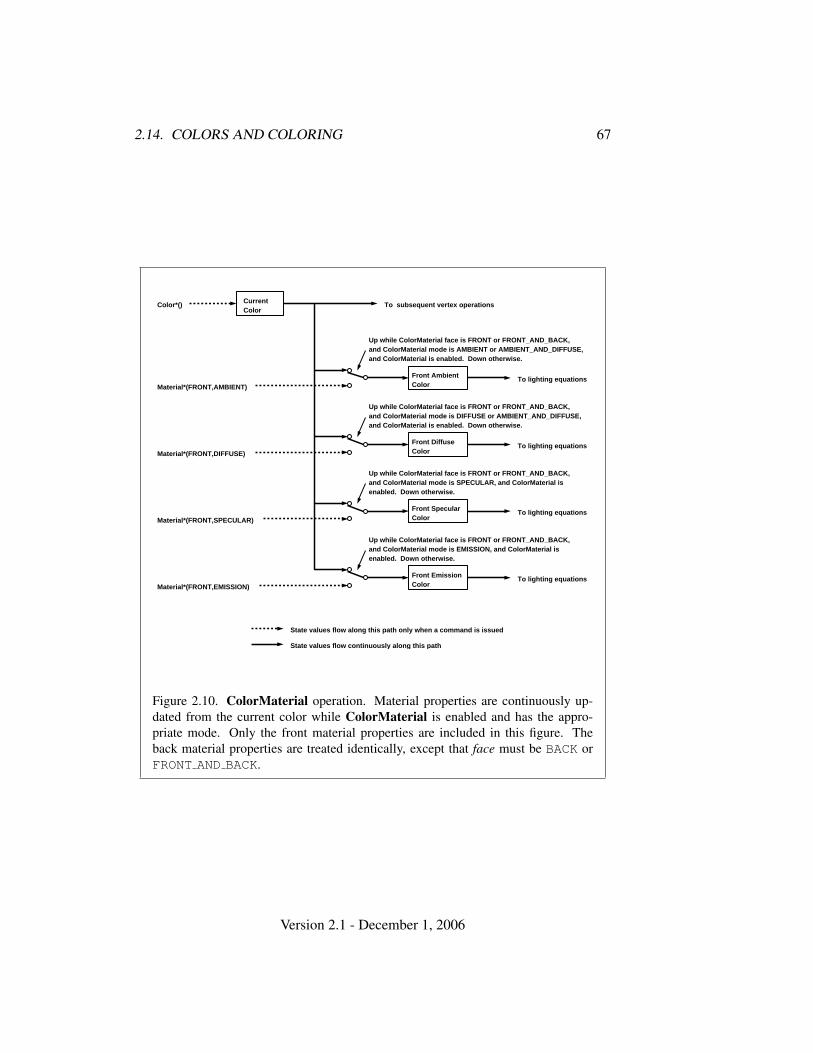
2.14. COLORS AND COLORING 67
CurrentColor
Front AmbientColor
Up while ColorMaterial face is FRONT or FRONT_AND_BACK,and ColorMaterial mode is AMBIENT or AMBIENT_AND_DIFFUSE,and ColorMaterial is enabled. Down otherwise.
Material*(FRONT,AMBIENT)To lighting equations
Front DiffuseColor
Up while ColorMaterial face is FRONT or FRONT_AND_BACK,and ColorMaterial mode is DIFFUSE or AMBIENT_AND_DIFFUSE,and ColorMaterial is enabled. Down otherwise.
Material*(FRONT,DIFFUSE)To lighting equations
Up while ColorMaterial face is FRONT or FRONT_AND_BACK,and ColorMaterial mode is SPECULAR, and ColorMaterial isenabled. Down otherwise.
Material*(FRONT,SPECULAR)To lighting equations
Front EmissionColor
Up while ColorMaterial face is FRONT or FRONT_AND_BACK,and ColorMaterial mode is EMISSION, and ColorMaterial isenabled. Down otherwise.
Material*(FRONT,EMISSION)To lighting equations
Front SpecularColor
Color*() To subsequent vertex operations
State values flow continuously along this path
State values flow along this path only when a command is issued
Figure 2.10. ColorMaterial operation. Material properties are continuously up-dated from the current color while ColorMaterial is enabled and has the appro-priate mode. Only the front material properties are included in this figure. Theback material properties are treated identically, except that face must be BACK orFRONT AND BACK.
Version 2.1 - December 1, 2006
68 CHAPTER 2. OPENGL OPERATION
ColorMaterial(FRONT, AMBIENT)
while COLOR MATERIAL is enabled sets the front material acm to the value of thecurrent color.
Material properties can be changed inside a Begin/End pair indirectly by en-abling ColorMaterial mode and making Color calls. However, when a vertexshader is active such property changes are not guaranteed to update material pa-rameters, defined in table 2.11, until the following End command.
2.14.4 Lighting State
The state required for lighting consists of all of the lighting parameters (frontand back material parameters, lighting model parameters, and at least 8 sets oflight parameters), a bit indicating whether a back color distinct from the frontcolor should be computed, at least 8 bits to indicate which lights are enabled,a five-valued variable indicating the current ColorMaterial mode, a bit indicat-ing whether or not COLOR MATERIAL is enabled, and a single bit to indicatewhether lighting is enabled or disabled. In the initial state, all lighting parame-ters have their default values. Back color evaluation does not take place, Color-Material is FRONT AND BACK and AMBIENT AND DIFFUSE, and both lighting andCOLOR MATERIAL are disabled.
2.14.5 Color Index Lighting
A simplified lighting computation applies in color index mode that uses many ofthe parameters controlling RGBA lighting, but none of the RGBA material param-eters. First, the RGBA diffuse and specular intensities of light i (dcli and scli,respectively) determine color index diffuse and specular light intensities, dli andsli from
dli = (.30)R(dcli) + (.59)G(dcli) + (.11)B(dcli)
andsli = (.30)R(scli) + (.59)G(scli) + (.11)B(scli).
R(x) indicates the R component of the color x and similarly for G(x) and B(x).Next, let
s =n∑
i=0
(atti)(spoti)(sli)(fi)(n� hi)srm
where atti and spoti are given by equations 2.4 and 2.5, respectively, and fi andhi are given by equations 2.2 and 2.3, respectively. Let s′ = min{s, 1}. Finally,
Version 2.1 - December 1, 2006
2.14. COLORS AND COLORING 69
let
d =n∑
i=0
(atti)(spoti)(dli)(n�−−→VPpli).
Then color index lighting produces a value c, given by
c = am + d(1− s′)(dm − am) + s′(sm − am).
The final color index isc′ = min{c, sm}.
The values am, dm and sm are material properties described in tables 2.10 and 2.11.Any ambient light intensities are incorporated into am. As with RGBA lighting,disabled lights cause the corresponding terms from the summations to be omitted.The interpretation of tbs and the calculation of front and back colors is carried outas has already been described for RGBA lighting.
The values am, dm, and sm are set with Material using a pname ofCOLOR INDEXES. Their initial values are 0, 1, and 1, respectively. The additionalstate consists of three floating-point values. These values have no effect on RGBAlighting.
2.14.6 Clamping or Masking
After lighting (whether enabled or not), all components of both primary and sec-ondary colors are clamped to the range [0, 1].
For a color index, the index is first converted to fixed-point with an unspecifiednumber of bits to the right of the binary point; the nearest fixed-point value isselected. Then, the bits to the right of the binary point are left alone while theinteger portion is masked (bitwise ANDed) with 2n − 1, where n is the number ofbits in a color in the color index buffer (buffers are discussed in chapter 4).
2.14.7 Flatshading
A primitive may be flatshaded, meaning that all vertices of the primitive are as-signed the same color index or the same primary and secondary colors. Thesecolors are the colors of the vertex that spawned the primitive. For a point, theseare the colors associated with the point. For a line segment, they are the colors ofthe second (final) vertex of the segment. For a polygon, they come from a selectedvertex depending on how the polygon was generated. Table 2.12 summarizes thepossibilities.
Flatshading is controlled by
Version 2.1 - December 1, 2006
70 CHAPTER 2. OPENGL OPERATION
Primitive type of polygon i Vertexsingle polygon (i ≡ 1) 1triangle strip i + 2triangle fan i + 2independent triangle 3i
quad strip 2i + 2independent quad 4i
Table 2.12: Polygon flatshading color selection. The colors used for flatshadingthe ith polygon generated by the indicated Begin/End type are derived from thecurrent color (if lighting is disabled) in effect when the indicated vertex is specified.If lighting is enabled, the colors are produced by lighting the indicated vertex.Vertices are numbered 1 through n, where n is the number of vertices between theBegin/End pair.
void ShadeModel( enum mode );
mode value must be either of the symbolic constants SMOOTH or FLAT. If mode isSMOOTH (the initial state), vertex colors are treated individually. If mode is FLAT,flatshading is turned on. ShadeModel thus requires one bit of state.
2.14.8 Color and Associated Data Clipping
After lighting, clamping or masking and possible flatshading, colors are clipped.Those colors associated with a vertex that lies within the clip volume are unaffectedby clipping. If a primitive is clipped, however, the colors assigned to verticesproduced by clipping are clipped colors.
Let the colors assigned to the two vertices P1 and P2 of an unclipped edge bec1 and c2. The value of t (section 2.12) for a clipped point P is used to obtain thecolor associated with P as
c = tc1 + (1− t)c2.
(For a color index color, multiplying a color by a scalar means multiplying theindex by the scalar. For an RGBA color, it means multiplying each of R, G, B, andA by the scalar. Both primary and secondary colors are treated in the same fashion.)Polygon clipping may create a clipped vertex along an edge of the clip volume’sboundary. This situation is handled by noting that polygon clipping proceeds byclipping against one plane of the clip volume’s boundary at a time. Color clipping
Version 2.1 - December 1, 2006
2.15. VERTEX SHADERS 71
is done in the same way, so that clipped points always occur at the intersection ofpolygon edges (possibly already clipped) with the clip volume’s boundary.
Texture and fog coordinates, vertex shader varying variables (section 2.15.3),and point sizes computed on a per vertex basis must also be clipped when a primi-tive is clipped. The method is exactly analogous to that used for color clipping.
2.14.9 Final Color Processing
For an RGBA color, each color component (which lies in [0, 1]) is converted(by rounding to nearest) to a fixed-point value with m bits. We assume thatthe fixed-point representation used represents each value k/(2m − 1), wherek ∈ {0, 1, . . . , 2m − 1}, as k (e.g. 1.0 is represented in binary as a string ofall ones). m must be at least as large as the number of bits in the correspondingcomponent of the framebuffer. m must be at least 2 for A if the framebuffer doesnot contain an A component, or if there is only 1 bit of A in the framebuffer. Acolor index is converted (by rounding to nearest) to a fixed-point value with at leastas many bits as there are in the color index portion of the framebuffer.
Because a number of the form k/(2m − 1) may not be represented exactly asa limited-precision floating-point quantity, we place a further requirement on thefixed-point conversion of RGBA components. Suppose that lighting is disabled, thecolor associated with a vertex has not been clipped, and one of Colorub, Colorus,or Colorui was used to specify that color. When these conditions are satisfied, anRGBA component must convert to a value that matches the component as specifiedin the Color command: if m is less than the number of bits b with which thecomponent was specified, then the converted value must equal the most significantm bits of the specified value; otherwise, the most significant b bits of the convertedvalue must equal the specified value.
2.15 Vertex Shaders
The sequence of operations described in sections 2.11 through 2.14 is a fixed-function method for processing vertex data. Applications can more generally de-scribe the operations that occur on vertex values and their associated data by usinga vertex shader.
A vertex shader is an array of strings containing source code for the operationsthat are meant to occur on each vertex that is processed. The language used forvertex shaders is described in the OpenGL Shading Language Specification.
To use a vertex shader, shader source code is first loaded into a shader objectand then compiled. One or more vertex shader objects are then attached to a pro-
Version 2.1 - December 1, 2006
72 CHAPTER 2. OPENGL OPERATION
gram object. A program object is then linked, which generates executable codefrom all the compiled shader objects attached to the program. When a linkedprogram object is used as the current program object, the executable code for thevertex shaders it contains is used to process vertices.
In addition to vertex shaders, fragment shaders can be created, compiled, andlinked into program objects. Fragment shaders affect the processing of fragmentsduring rasterization, and are described in section 3.11. A single program objectcan contain both vertex and fragment shaders.
When the program object currently in use includes a vertex shader, its vertexshader is considered active and is used to process vertices. If the program objecthas no vertex shader, or no program object is currently in use, the fixed-functionmethod for processing vertices is used instead.
2.15.1 Shader Objects
The source code that makes up a program that gets executed by one of the pro-grammable stages is encapsulated in one or more shader objects.
The name space for shader objects is the unsigned integers, with zero re-served for the GL. This name space is shared with program objects. The followingsections define commands that operate on shader and program objects by name.Commands that accept shader or program object names will generate the errorINVALID VALUE if the provided name is not the name of either a shader or pro-gram object and INVALID OPERATION if the provided name identifies an objectthat is not the expected type.
To create a shader object, use the command
uint CreateShader( enum type );
The shader object is empty when it is created. The type argument specifies the typeof shader object to be created. For vertex shaders, type must be VERTEX SHADER.A non-zero name that can be used to reference the shader object is returned. If anerror occurs, zero will be returned.
The command
void ShaderSource( uint shader, sizei count, constchar **string, const int *length );
loads source code into the shader object named shader. string is an array of countpointers to optionally null-terminated character strings that make up the sourcecode. The length argument is an array with the number of chars in each string (the
Version 2.1 - December 1, 2006

2.15. VERTEX SHADERS 73
string length). If an element in length is negative, its accompanying string is null-terminated. If length is NULL, all strings in the string argument are considered null-terminated. The ShaderSource command sets the source code for the shader tothe text strings in the string array. If shader previously had source code loaded intoit, the existing source code is completely replaced. Any length passed in excludesthe null terminator in its count.
The strings that are loaded into a shader object are expected to form the sourcecode for a valid shader as defined in the OpenGL Shading Language Specification.
Once the source code for a shader has been loaded, a shader object can becompiled with the command
void CompileShader( uint shader );
Each shader object has a boolean status, COMPILE STATUS, that is modified asa result of compilation. This status can be queried with GetShaderiv (see sec-tion 6.1.14). This status will be set to TRUE if shader was compiled without errorsand is ready for use, and FALSE otherwise. Compilation can fail for a variety ofreasons as listed in the OpenGL Shading Language Specification. If Compile-Shader failed, any information about a previous compile is lost. Thus a failedcompile does not restore the old state of shader.
Changing the source code of a shader object with ShaderSource does notchange its compile status or the compiled shader code.
Each shader object has an information log, which is a text string that is over-written as a result of compilation. This information log can be queried with Get-ShaderInfoLog to obtain more information about the compilation attempt (seesection 6.1.14).
Shader objects can be deleted with the command
void DeleteShader( uint shader );
If shader is not attached to any program object, it is deleted immediately. Oth-erwise, shader is flagged for deletion and will be deleted when it is no longerattached to any program object. If an object is flagged for deletion, its booleanstatus bit DELETE STATUS is set to true. The value of DELETE STATUS can bequeried with GetShaderiv (see section 6.1.14). DeleteShader will silently ignorethe value zero.
2.15.2 Program Objects
The shader objects that are to be used by the programmable stages of the GL arecollected together to form a program object. The programs that are executed by
Version 2.1 - December 1, 2006
74 CHAPTER 2. OPENGL OPERATION
these programmable stages are called executables. All information necessary fordefining an executable is encapsulated in a program object. A program object iscreated with the command
uint CreateProgram( void );
Program objects are empty when they are created. A non-zero name that can beused to reference the program object is returned. If an error occurs, 0 will bereturned.
To attach a shader object to a program object, use the command
void AttachShader( uint program, uint shader );
The error INVALID OPERATION is generated if shader is already attached to pro-gram.
Shader objects may be attached to program objects before source code hasbeen loaded into the shader object, or before the shader object has been compiled.Multiple shader objects of the same type may be attached to a single programobject, and a single shader object may be attached to more than one program object.
To detach a shader object from a program object, use the command
void DetachShader( uint program, uint shader );
The error INVALID OPERATION is generated if shader is not attached to program.If shader has been flagged for deletion and is not attached to any other programobject, it is deleted.
In order to use the shader objects contained in a program object, the programobject must be linked. The command
void LinkProgram( uint program );
will link the program object named program. Each program object has a booleanstatus, LINK STATUS, that is modified as a result of linking. This status can bequeried with GetProgramiv (see section 6.1.14). This status will be set to TRUE ifa valid executable is created, and FALSE otherwise. Linking can fail for a varietyof reasons as specified in the OpenGL Shading Language Specification. Linkingwill also fail if one or more of the shader objects, attached to program are notcompiled successfully, or if more active uniform or active sampler variables areused in program than allowed (see section 2.15.3). If LinkProgram failed, anyinformation about a previous link of that program object is lost. Thus, a failed linkdoes not restore the old state of program.
Version 2.1 - December 1, 2006
2.15. VERTEX SHADERS 75
Each program object has an information log that is overwritten as a result of alink operation. This information log can be queried with GetProgramInfoLog toobtain more information about the link operation or the validation information (seesection 6.1.14).
If a valid executable is created, it can be made part of the current renderingstate with the command
void UseProgram( uint program );
This command will install the executable code as part of current rendering state ifthe program object program contains valid executable code, i.e. has been linkedsuccessfully. If UseProgram is called with program set to 0, it is as if the GLhad no programmable stages and the fixed-function paths will be used instead.If program has not been successfully linked, the error INVALID OPERATION isgenerated and the current rendering state is not modified.
While a program object is in use, applications are free to modify attachedshader objects, compile attached shader objects, attach additional shader objects,and detach shader objects. These operations do not affect the link status or exe-cutable code of the program object.
If the program object that is in use is re-linked successfully, the LinkProgramcommand will install the generated executable code as part of the current renderingstate if the specified program object was already in use as a result of a previous callto UseProgram.
If that program object that is in use is re-linked unsuccessfully, the link statuswill be set to FALSE, but existing executable and associated state will remain partof the current rendering state until a subsequent call to UseProgram removes itfrom use. After such a program is removed from use, it can not be made part of thecurrent rendering state until it is successfully re-linked.
Program objects can be deleted with the command
void DeleteProgram( uint program );
If program is not the current program for any GL context, it is deleted immediately.Otherwise, program is flagged for deletion and will be deleted when it is no longerthe current program for any context. When a program object is deleted, all shaderobjects attached to it are detached. DeleteProgram will silently ignore the valuezero.
2.15.3 Shader Variables
A vertex shader can reference a number of variables as it executes. Vertex attributesare the per-vertex values specified in section 2.7. Uniforms are per-program vari-
Version 2.1 - December 1, 2006
76 CHAPTER 2. OPENGL OPERATION
ables that are constant during program execution. Samplers are a special form ofuniform used for texturing (section 3.8). Varying variables hold the results of ver-tex shader execution that are used later in the pipeline. The following sectionsdescribe each of these variable types.
Vertex Attributes
Vertex shaders can access built-in vertex attribute variables corresponding to theper-vertex state set by commands such as Vertex, Normal, Color. Vertex shaderscan also define named attribute variables, which are bound to the generic vertexattributes that are set by VertexAttrib*. This binding can be specified by the ap-plication before the program is linked, or automatically assigned by the GL whenthe program is linked.
When an attribute variable declared as a float, vec2, vec3 or vec4 is boundto a generic attribute index i, its value(s) are taken from the x, (x, y), (x, y, z), or(x, y, z, w) components, respectively, of the generic attribute i. When an attributevariable is declared as a mat2, mat3x2 or mat4x2, its matrix columns are takenfrom the (x, y) components of generic attributes i and i+1 (mat2), from attributesi through i + 2 (mat3x2), or from attributes i through i + 3 (mat4x2). When anattribute variable is declared as a mat2x3, mat3 or mat4x3, its matrix columnsare taken from the (x, y, z) components of generic attributes i and i+1 (mat2x3),from attributes i through i+2 (mat3), or from attributes i through i+3 (mat4x3).When an attribute variable is declared as a mat2x4, mat3x4 or mat4, its matrixcolumns are taken from the (x, y, z, w) components of generic attributes i and i+1(mat2x4), from attributes i through i + 2 (mat3x4), or from attributes i throughi + 3 (mat4).
An attribute variable (either conventional or generic) is considered active if it isdetermined by the compiler and linker that the attribute may be accessed when theshader is executed. Attribute variables that are declared in a vertex shader but neverused will not count against the limit. In cases where the compiler and linker cannotmake a conclusive determination, an attribute will be considered active. A programobject will fail to link if the sum of the active generic and active conventionalattributes exceeds MAX VERTEX ATTRIBS.
To determine the set of active vertex attributes used by a program, and to de-termine their types, use the command:
void GetActiveAttrib( uint program, uint index,sizei bufSize, sizei *length, int *size, enum *type,char *name );
Version 2.1 - December 1, 2006
2.15. VERTEX SHADERS 77
This command provides information about the attribute selected by index. An in-dex of 0 selects the first active attribute, and an index of ACTIVE ATTRIBUTES− 1selects the last active attribute. The value of ACTIVE ATTRIBUTES can be queriedwith GetProgramiv (see section 6.1.14). If index is greater than or equal toACTIVE ATTRIBUTES, the error INVALID VALUE is generated. Note that indexsimply identifies a member in a list of active attributes, and has no relation to thegeneric attribute that the corresponding variable is bound to.
The parameter program is the name of a program object for which the com-mand LinkProgram has been issued in the past. It is not necessary for program tohave been linked successfully. The link could have failed because the number ofactive attributes exceeded the limit.
The name of the selected attribute is returned as a null-terminated string inname. The actual number of characters written into name, excluding the null termi-nator, is returned in length. If length is NULL, no length is returned. The maximumnumber of characters that may be written into name, including the null terminator,is specified by bufSize. The returned attribute name can be the name of a genericattribute or a conventional attribute (which begin with the prefix "gl ", see theOpenGL Shading Language specification for a complete list). The length of thelongest attribute name in program is given by ACTIVE ATTRIBUTE MAX LENGTH,which can be queried with GetProgramiv (see section 6.1.14).
For the selected attribute, the type of the attribute is returned into type.The size of the attribute is returned into size. The value in size is inunits of the type returned in type. The type returned can be any ofFLOAT, FLOAT VEC2, FLOAT VEC3, FLOAT VEC4, FLOAT MAT2, FLOAT MAT3,FLOAT MAT4, FLOAT MAT2x3, FLOAT MAT2x4, FLOAT MAT3x2, FLOAT MAT3x4,FLOAT MAT4x2, or FLOAT MAT4x3.
If an error occurred, the return parameters length, size, type and name will beunmodified.
This command will return as much information about active attributes as pos-sible. If no information is available, length will be set to zero and name will be anempty string. This situation could arise if GetActiveAttrib is issued after a failedlink.
After a program object has been linked successfully, the bindings of attributevariable names to indices can be queried. The command
int GetAttribLocation( uint program, const char *name );
returns the generic attribute index that the attribute variable named name was boundto when the program object named program was last linked. name must be a null-terminated string. If name is active and is an attribute matrix, GetAttribLocation
Version 2.1 - December 1, 2006
78 CHAPTER 2. OPENGL OPERATION
returns the index of the first column of that matrix. If program has not been suc-cessfully linked, the error INVALID OPERATION is generated. If name is not anactive attribute, if name is a conventional attribute, or if an error occurs, -1 will bereturned.
The binding of an attribute variable to a generic attribute index can also bespecified explicitly. The command
void BindAttribLocation( uint program, uint index, constchar *name );
specifies that the attribute variable named name in program program should bebound to generic vertex attribute index when the program is next linked. If namewas bound previously, its assigned binding is replaced with index. name must be anull terminated string. The error INVALID VALUE is generated if index is equal orgreater than MAX VERTEX ATTRIBS. BindAttribLocation has no effect until theprogram is linked. In particular, it doesn’t modify the bindings of active attributevariables in a program that has already been linked.
Built-in attribute variables are automatically bound to conventional attributes,and can not have an assigned binding. The error INVALID OPERATION is gener-ated if name starts with the reserved "gl " prefix.
When a program is linked, any active attributes without a binding specifiedthrough BindAttribLocation will be automatically be bound to vertex attributesby the GL. Such bindings can be queried using the command GetAttribLocation.LinkProgram will fail if the assigned binding of an active attribute variable wouldcause the GL to reference a non-existant generic attribute (one greater than or equalto MAX VERTEX ATTRIBS). LinkProgram will fail if the attribute bindings as-signed by BindAttribLocation do not leave not enough space to assign a locationfor an active matrix attribute, which requires multiple contiguous generic attributes.LinkProgram will also fail if the vertex shaders used in the program object containassignments (not removed during pre-processing) to an attribute variable bound togeneric attribute zero and to the conventional vertex position (gl Vertex).
BindAttribLocation may be issued before any vertex shader objects are at-tached to a program object. Hence it is allowed to bind any name (except a namestarting with "gl ") to an index, including a name that is never used as an attributein any vertex shader object. Assigned bindings for attribute variables that do notexist or are not active are ignored.
The values of generic attributes sent to generic attribute index i are part ofcurrent state, just like the conventional attributes. If a new program object hasbeen made active, then these values will be tracked by the GL in such a way thatthe same values will be observed by attributes in the new program object that arealso bound to index i.
Version 2.1 - December 1, 2006
2.15. VERTEX SHADERS 79
It is possible for an application to bind more than one attribute name to thesame location. This is referred to as aliasing. This will only work if only one ofthe aliased attributes is active in the executable program, or if no path through theshader consumes more than one attribute of a set of attributes aliased to the samelocation. A link error can occur if the linker determines that every path through theshader consumes multiple aliased attributes, but implementations are not requiredto generate an error in this case. The compiler and linker are allowed to assume thatno aliasing is done, and may employ optimizations that work only in the absenceof aliasing. It is not possible to alias generic attributes with conventional ones.
Uniform Variables
Shaders can declare named uniform variables, as described in the OpenGL ShadingLanguage Specification. Values for these uniforms are constant over a primitive,and typically they are constant across many primitives. Uniforms are programobject-specific state. They retain their values once loaded, and their values arerestored whenever a program object is used, as long as the program object has notbeen re-linked. A uniform is considered active if it is determined by the compilerand linker that the uniform will actually be accessed when the executable codeis executed. In cases where the compiler and linker cannot make a conclusivedetermination, the uniform will be considered active.
The amount of storage available for uniform variables accessed bya vertex shader is specified by the implementation dependent constantMAX VERTEX UNIFORM COMPONENTS. This value represents the number of indi-vidual floating-point, integer, or boolean values that can be held in uniform variablestorage for a vertex shader. A link error will be generated if an attempt is made toutilize more than the space available for vertex shader uniform variables.
When a program is successfully linked, all active uniforms belonging to theprogram object are initialized to zero (FALSE for booleans). A successful link willalso generate a location for each active uniform. The values of active uniforms canbe changed using this location and the appropriate Uniform* command (see be-low). These locations are invalidated and new ones assigned after each successfulre-link.
To find the location of an active uniform variable within a program object, usethe command
int GetUniformLocation( uint program, constchar *name );
This command will return the location of uniform variable name. name must be anull terminated string, without white space. The value -1 will be returned if name
Version 2.1 - December 1, 2006
80 CHAPTER 2. OPENGL OPERATION
does not correspond to an active uniform variable name in program or if name startswith the reserved prefix "gl ". If program has not been successfully linked, theerror INVALID OPERATION is generated. After a program is linked, the locationof a uniform variable will not change, unless the program is re-linked.
A valid name cannot be a structure, an array of structures, or any portion ofa single vector or a matrix. In order to identify a valid name, the "." (dot) and"[]" operators can be used in name to specify a member of a structure or elementof an array.
The first element of a uniform array is identified using the name of the uniformarray appended with "[0]". Except if the last part of the string name indicates auniform array, then the location of the first element of that array can be retrievedby either using the name of the uniform array, or the name of the uniform arrayappended with "[0]".
To determine the set of active uniform attributes used by a program, and todetermine their sizes and types, use the command:
void GetActiveUniform( uint program, uint index,sizei bufSize, sizei *length, int *size, enum *type,char *name );
This command provides information about the uniform selected by index. An in-dex of 0 selects the first active uniform, and an index of ACTIVE UNIFORMS − 1selects the last active uniform. The value of ACTIVE UNIFORMS can be queriedwith GetProgramiv (see section 6.1.14). If index is greater than or equal toACTIVE UNIFORMS, the error INVALID VALUE is generated. Note that index sim-ply identifies a member in a list of active uniforms, and has no relation to thelocation assigned to the corresponding uniform variable.
The parameter program is a name of a program object for which the commandLinkProgram has been issued in the past. It is not necessary for program to havebeen linked successfully. The link could have failed because the number of activeuniforms exceeded the limit.
If an error occurred, the return parameters length, size, type and name will beunmodified.
For the selected uniform, the uniform name is returned into name. The stringname will be null terminated. The actual number of characters written into name,excluding the null terminator, is returned in length. If length is NULL, no length isreturned. The maximum number of characters that may be written into name, in-cluding the null terminator, is specified by bufSize. The returned uniform namecan be the name of built-in uniform state as well. The complete list of built-in uniform state is described in section 7.5 of the OpenGL Shading Language
Version 2.1 - December 1, 2006
2.15. VERTEX SHADERS 81
specification. The length of the longest uniform name in program is given byACTIVE UNIFORM MAX LENGTH, which can be queried with GetProgramiv (seesection 6.1.14).
Each uniform variable, declared in a shader, is broken down into one or morestrings using the "." (dot) and "[]" operators, if necessary, to the point that itis legal to pass each string back into GetUniformLocation. Each of these stringsconstitutes one active uniform, and each string is assigned an index.
For the selected uniform, the type of the uniform is returned intotype. The size of the uniform is returned into size. The value insize is in units of the type returned in type. The type returned can beany of FLOAT, FLOAT VEC2, FLOAT VEC3, FLOAT VEC4, INT, INT VEC2,INT VEC3, INT VEC4, BOOL, BOOL VEC2, BOOL VEC3, BOOL VEC4, FLOAT MAT2,FLOAT MAT3, FLOAT MAT4, FLOAT MAT2x3, FLOAT MAT2x4, FLOAT MAT3x2,FLOAT MAT3x4, FLOAT MAT4x2, FLOAT MAT4x3, SAMPLER 1D, SAMPLER 2D,SAMPLER 3D, SAMPLER CUBE, SAMPLER 1D SHADOW, or SAMPLER 2D SHADOW.
If one or more elements of an array are active, GetActiveUniform will returnthe name of the array in name, subject to the restrictions listed above. The type ofthe array is returned in type. The size parameter contains the highest array elementindex used, plus one. The compiler or linker determines the highest index used.There will be only one active uniform reported by the GL per uniform array.
GetActiveUniform will return as much information about active uniforms aspossible. If no information is available, length will be set to zero and name will bean empty string. This situation could arise if GetActiveUniform is issued after afailed link.
To load values into the uniform variables of the program object that is currentlyin use, use the commands
void Uniform{1234}{if}( int location, T value );void Uniform{1234}{if}v( int location, sizei count,
T value );void UniformMatrix{234}fv( int location, sizei count,
boolean transpose, const float *value );void UniformMatrix{2x3,3x2,2x4,4x2,3x4,4x3}fv(
int location, sizei count, boolean transpose, constfloat *value );
The given values are loaded into the uniform variable location identified by loca-tion.
The Uniform*f{v} commands will load count sets of one to four floating-pointvalues into a uniform location defined as a float, a floating-point vector, an array offloats, or an array of floating-point vectors.
Version 2.1 - December 1, 2006
82 CHAPTER 2. OPENGL OPERATION
The Uniform*i{v} commands will load count sets of one to four integer val-ues into a uniform location defined as a sampler, an integer, an integer vector, anarray of samplers, an array of integers, or an array of integer vectors. Only theUniform1i{v} commands can be used to load sampler values (see below).
The UniformMatrix{234}fv commands will load count 2× 2, 3× 3, or 4× 4matrices (corresponding to 2, 3, or 4 in the command name) of floating-point valuesinto a uniform location defined as a matrix or an array of matrices. If transposeis FALSE, the matrix is specified in column major order, otherwise in row majororder.
The UniformMatrix{2x3,3x2,2x4,4x2,3x4,4x3}fv commands will load count2×3, 3×2, 2×4, 4×2, 3×4, or 4×3 matrices (corresponding to the numbers in thecommand name) of floating-point values into a uniform location defined as a matrixor an array of matrices. The first number in the command name is the number ofcolumns; the second is the number of rows. For example, UniformMatrix2x4fvis used to load a matrix consisting of two columns and four rows. If transposeis FALSE, the matrix is specified in column major order, otherwise in row majororder.
When loading values for a uniform declared as a boolean, a boolean vector,an array of booleans, or an array of boolean vectors, both the Uniform*i{v} andUniform*f{v} set of commands can be used to load boolean values. Type con-version is done by the GL. The uniform is set to FALSE if the input value is 0 or0.0f, and set to TRUE otherwise. The Uniform* command used must match thesize of the uniform, as declared in the shader. For example, to load a uniformdeclared as a bvec2, either Uniform2i{v} or Uniform2f{v} can be used. AnINVALID OPERATION error will be generated if an attempt is made to use a non-matching Uniform* command. In this example using Uniform1iv would generatean error.
For all other uniform types the Uniform* command used must match the sizeand type of the uniform, as declared in the shader. No type conversions are done.For example, to load a uniform declared as a vec4, Uniform4f{v} must be used.To load a 3x3 matrix, UniformMatrix3fv must be used. An INVALID OPERATION
error will be generated if an attempt is made to use a non-matching Uniform*command. In this example, using Uniform4i{v} would generate an error.
When loading N elements starting at an arbitrary position k in a uniform de-clared as an array, elements k through k + N − 1 in the array will be replacedwith the new values. Values for any array element that exceeds the highest arrayelement index used, as reported by GetActiveUniform, will be ignored by the GL.
If the value of location is -1, the Uniform* commands will silently ignore thedata passed in, and the current uniform values will not be changed.
If any of the following conditions occur, an INVALID OPERATION error is gen-
Version 2.1 - December 1, 2006
2.15. VERTEX SHADERS 83
erated by the Uniform* commands, and no uniform values are changed:
• if the size indicated in the name of the Uniform* command used does notmatch the size of the uniform declared in the shader,
• if the uniform declared in the shader is not of type boolean and the typeindicated in the name of the Uniform* command used does not match thetype of the uniform,
• if count is greater than one, and the uniform declared in the shader is not anarray variable,
• if no variable with a location of location exists in the program object cur-rently in use and location is not -1, or
• if there is no program object currently in use.
Samplers
Samplers are special uniforms used in the OpenGL Shading Language to identifythe texture object used for each texture lookup. The value of a sampler indicatesthe texture image unit being accessed. Setting a sampler’s value to i selects textureimage unit number i. The values of i range from zero to the implementation-dependent maximum supported number of texture image units.
The type of the sampler identifies the target on the texture image unit. Thetexture object bound to that texture image unit’s target is then used for the texturelookup. For example, a variable of type sampler2D selects target TEXTURE 2D onits texture image unit. Binding of texture objects to targets is done as usual withBindTexture. Selecting the texture image unit to bind to is done as usual withActiveTexture.
The location of a sampler needs to be queried with GetUniformLocation, justlike any uniform variable. Sampler values need to be set by calling Uniform1i{v}.Loading samplers with any of the other Uniform* entry points is not allowed andwill result in an INVALID OPERATION error.
It is not allowed to have variables of different sampler types pointing to thesame texture image unit within a program object. This situation can only be de-tected at the next rendering command issued, and an INVALID OPERATION errorwill then be generated.
Active samplers are samplers actually being used in a program object. TheLinkProgram command determines if a sampler is active or not. The LinkPro-gram command will attempt to determine if the active samplers in the shader(s)
Version 2.1 - December 1, 2006
84 CHAPTER 2. OPENGL OPERATION
contained in the program object exceed the maximum allowable limits. If it de-termines that the count of active samplers exceeds the allowable limits, then thelink fails (these limits can be different for different types of shaders). Each activesampler variable counts against the limit, even if multiple samplers refer to thesame texture image unit. If this cannot be determined at link time, for example ifthe program object only contains a vertex shader, then it will be determined at thenext rendering command issued, and an INVALID OPERATION error will then begenerated.
Varying Variables
A vertex shader may define one or more varying variables (see the OpenGL Shad-ing Language specification). These values are expected to be interpolated acrossthe primitive being rendered. The OpenGL Shading Language specification definesa set of built-in varying variables for vertex shaders that correspond to the valuesrequired for the fixed-function processing that occurs after vertex processing.
The number of interpolators available for processing varying variables is givenby the implementation-dependent constant MAX VARYING FLOATS. This value rep-resents the number of individual floating-point values that can be interpolated;varying variables declared as vectors, matrices, and arrays will all consume multi-ple interpolators. When a program is linked, all components of any varying vari-able written by a vertex shader, or read by a fragment shader, will count againstthis limit. The transformed vertex position (gl Position) is not a varying vari-able and does not count against this limit. A program whose shaders access morethan MAX VARYING FLOATS components worth of varying variables may fail tolink, unless device-dependent optimizations are able to make the program fit withinavailable hardware resources.
2.15.4 Shader Execution
If a successfully linked program object that contains a vertex shader is made currentby calling UseProgram, the executable version of the vertex shader is used toprocess incoming vertex values rather than the fixed-function vertex processingdescribed in sections 2.11 through 2.14. In particular,
• The model-view and projection matrices are not applied to vertex coordi-nates (section 2.11).
• The texture matrices are not applied to texture coordinates (section 2.11.2).
• Normals are not transformed to eye coordinates, and are not rescaled or nor-malized (section 2.11.3).
Version 2.1 - December 1, 2006
2.15. VERTEX SHADERS 85
• Normalization of AUTO NORMAL evaluated normals is not performed. (sec-tion 5.1).
• Texture coordinates are not generated automatically (section 2.11.4).
• Per vertex lighting is not performed (section 2.14.1).
• Color material computations are not performed (section 2.14.3).
• Color index lighting is not performed (section 2.14.5).
• All of the above applies when setting the current raster position (sec-tion 2.13).
The following operations are applied to vertex values that are the result ofexecuting the vertex shader:
• Color clamping or masking (section 2.14.6).
• Perspective division on clip coordinates (section 2.11).
• Viewport mapping, including depth range scaling (section 2.11.1).
• Clipping, including client-defined clip planes (section 2.12).
• Front face determination (section 2.14.1).
• Flat-shading (section 2.14.7).
• Color, texture coordinate, fog, point-size and generic attribute clipping (sec-tion 2.14.8).
• Final color processing (section 2.14.9.
There are several special considerations for vertex shader execution describedin the following sections.
Texture Access
Vertex shaders have the ability to do a lookup into a texture map, if sup-ported by the GL implementation. The maximum number of texture image unitsavailable to a vertex shader is MAX VERTEX TEXTURE IMAGE UNITS; a maxi-mum number of zero indicates that the GL implemenation does not supporttexture accesses in vertex shaders. The maximum number of texture imageunits available to the fragment stage of the GL is MAX TEXTURE IMAGE UNITS.
Version 2.1 - December 1, 2006
86 CHAPTER 2. OPENGL OPERATION
Both the vertex shader and fragment processing combined cannot use morethan MAX COMBINED TEXTURE IMAGE UNITS texture image units. If boththe vertex shader and the fragment processing stage access the same textureimage unit, then that counts as using two texture image units against theMAX COMBINED TEXTURE IMAGE UNITS limit.
When a texture lookup is performed in a vertex shader, the filtered texture valueτ is computed in the manner described in sections 3.8.8 and 3.8.9, and convertedit to a texture source color Cs according to table 3.20 (section 3.8.13). A four-component vector (Rs, Gs, Bs, As) is returned to the vertex shader.
In a vertex shader, it is not possible to perform automatic level-of-detail calcu-lations using partial derivatives of the texture coordinates with respect to windowcoordinates as described in section 3.8.8. Hence, there is no automatic selection ofan image array level. Minification or magnification of a texture map is controlledby a level-of-detail value optionally passed as an argument in the texture lookupfunctions. If the texture lookup function supplies an explicit level-of-detail value l,then the pre-bias level-of-detail value λbase(x, y) = l (replacing equation 3.18). Ifthe texture lookup function does not supply an explicit level-of-detail value, thenλbase(x, y) = 0. The scale factor ρ(x, y) and its approximation function f(x, y)(see equation 3.21) are ignored.
Texture lookups involving textures with depth component data can either re-turn the depth data directly or return the results of a comparison with the r tex-ture coordinate used to perform the lookup, as described in section 3.8.14. Thecomparison operation is requested in the shader by using the shadow samplertypes (sampler1DShadow or sampler2DShadow) and in the texture using theTEXTURE COMPARE MODE parameter. These requests must be consistent; the re-sults of a texture lookup are undefined if:
• The sampler used in a texture lookup function is of type sampler1D orsampler2D, and the texture object’s internal format is DEPTH COMPONENT,and the TEXTURE COMPARE MODE is not NONE.
• The sampler used in a texture lookup function is of type sampler1DShadowor sampler2DShadow, and the texture object’s internal format isDEPTH COMPONENT, and the TEXTURE COMPARE MODE is NONE.
• The sampler used in a texture lookup function is of type sampler1DShadowor sampler2DShadow, and the texture object’s internal format is notDEPTH COMPONENT.
If a vertex shader uses a sampler where the associated texture object is not com-plete, as defined in section 3.8.10, the texture image unit will return (R,G,B,A)= (0, 0, 0, 1).
Version 2.1 - December 1, 2006
2.15. VERTEX SHADERS 87
Position Invariance
If a vertex shader uses the built-in function ftransform to generate a vertex posi-tion, then this generally guarantees that the transformed position will be the samewhether using this vertex shader or the fixed-function pipeline. This allows for cor-rect multi-pass rendering algorithms, where some passes use fixed-function vertextransformation and other passes use a vertex shader. If a vertex shader does not useftransform to generate a position, transformed positions are not guaranteed tomatch, even if the sequence of instructions used to compute the position match thesequence of transformations described in section 2.11.
Validation
It is not always possible to determine at link time if a program object actuallywill execute. Therefore validation is done when the first rendering command isissued, to determine if the currently active program object can be executed. Ifit cannot be executed then no fragments will be rendered, and Begin, Raster-Pos, or any command that performs an implicit Begin will generate the errorINVALID OPERATION.
This error is generated by Begin, RasterPos, or any command that performsan implicit Begin if:
• any two active samplers in the current program object are of different types,but refer to the same texture image unit,
• any active sampler in the current program object refers to a texture imageunit where fixed-function fragment processing accesses a texture target thatdoes not match the sampler type, or
• the sum of the number of active samplers in the program and the number oftexture image units enabled for fixed-function fragment processing exceedsthe combined limit on the total number of texture image units allowed.
Fixed-function fragment processing operations will be performed if the pro-gram object in use has no fragment shader.
The INVALID OPERATION error reported by these rendering commands maynot provide enough information to find out why the currently active program objectwould not execute. No information at all is available about a program object thatwould still execute, but is inefficient or suboptimal given the current GL state. Asa development aid, use the command
void ValidateProgram( uint program );
Version 2.1 - December 1, 2006
88 CHAPTER 2. OPENGL OPERATION
to validate the program object program against the current GL state. Each programobject has a boolean status, VALIDATE STATUS, that is modified as a result ofvalidation. This status can be queried with GetProgramiv (see section 6.1.14).If validation succeeded this status will be set to TRUE, otherwise it will be set toFALSE. If validation succeeded the program object is guaranteed to execute, giventhe current GL state. If validation failed, the program object is guaranteed to notexecute, given the current GL state.
ValidateProgram will check for all the conditions that could lead to anINVALID OPERATION error when rendering commands are issued, and may checkfor other conditions as well. For example, it could give a hint on how to optimizesome piece of shader code. The information log of program is overwritten withinformation on the results of the validation, which could be an empty string. Theresults written to the information log are typically only useful during applicationdevelopment; an application should not expect different GL implementations toproduce identical information.
A shader should not fail to compile, and a program object should not fail tolink due to lack of instruction space or lack of temporary variables. Implementa-tions should ensure that all valid shaders and program objects may be successfullycompiled, linked and executed.
Undefined Behavior
When using array or matrix variables in a shader, it is possible to access a vari-able with an index computed at run time that is outside the declared extent of thevariable. Such out-of-bounds reads will return undefined values; out-of-boundswrites will have undefined results and could corrupt other variables used by shaderor the GL. The level of protection provided against such errors in the shader isimplementation-dependent.
2.15.5 Required State
The GL maintains state to indicate which shader and program object names are inuse. Initially, no shader or program objects exist, and no names are in use.
The state required per shader object consists of:
• An unsigned integer specifying the shader object name.
• An integer holding the value of SHADER TYPE.
• A boolean holding the delete status, initially FALSE.
• A boolean holding the status of the last compile, initially FALSE.
Version 2.1 - December 1, 2006
2.15. VERTEX SHADERS 89
• An array of type char containing the information log, initially empty.
• An integer holding the length of the information log.
• An array of type char containing the concatenated shader string, initiallyempty.
• An integer holding the length of the concatenated shader string.
The state required per program object consists of:
• An unsigned integer indicating the program object object name.
• A boolean holding the delete status, initially FALSE.
• A boolean holding the status of the last link attempt, initially FALSE.
• A boolean holding the status of the last validation attempt, initally FALSE.
• An integer holding the number of attached shader objects.
• A list of unsigned integers to keep track of the names of the shader objectsattached.
• An array of type char containing the information log, initially empty.
• An integer holding the length of the information log.
• An integer holding the number of active uniforms.
• For each active uniform, three integers, holding its location, size, and type,and an array of type char holding its name.
• An array of words that hold the values of each active uniform.
• An integer holding the number of active attributes.
• For each active attribute, three integers holding its location, size, and type,and an array of type char holding its name.
Additional state required to support vertex shaders consists of:
• A bit indicating whether or not vertex program two-sided color mode is en-abled, initially disabled.
• A bit indicating whether or not vertex program point size mode (sec-tion 3.3.1) is enabled, initially disabled.
Additionally, one unsigned integer is required to hold the name of the current pro-gram object, if any.
Version 2.1 - December 1, 2006
Chapter 3
Rasterization
Rasterization is the process by which a primitive is converted to a two-dimensionalimage. Each point of this image contains such information as color and depth.Thus, rasterizing a primitive consists of two parts. The first is to determine whichsquares of an integer grid in window coordinates are occupied by the primitive. Thesecond is assigning a depth value and one or more color values to each such square.The results of this process are passed on to the next stage of the GL (per-fragmentoperations), which uses the information to update the appropriate locations in theframebuffer. Figure 3.1 diagrams the rasterization process. The color values as-signed to a fragment are initially determined by the rasterization operations (sec-tions 3.3 through 3.7) and modified by either the execution of the texturing, colorsum, and fog operations defined in sections 3.8, 3.9, and 3.10, or by a fragmentshader as defined in section 3.11. The final depth value is initially determined bythe rasterization operations and may be modified or replaced by a fragment shader.The results from rasterizing a point, line, polygon, pixel rectangle or bitmap can berouted through a fragment shader.
A grid square along with its parameters of assigned colors, z (depth), fog coor-dinate, and texture coordinates is called a fragment; the parameters are collectivelydubbed the fragment’s associated data. A fragment is located by its lower left cor-ner, which lies on integer grid coordinates. Rasterization operations also refer to afragment’s center, which is offset by (1/2, 1/2) from its lower left corner (and solies on half-integer coordinates).
Grid squares need not actually be square in the GL. Rasterization rules are notaffected by the actual aspect ratio of the grid squares. Display of non-square grids,however, will cause rasterized points and line segments to appear fatter in onedirection than the other. We assume that fragments are square, since it simplifiesantialiasing and texturing.
90
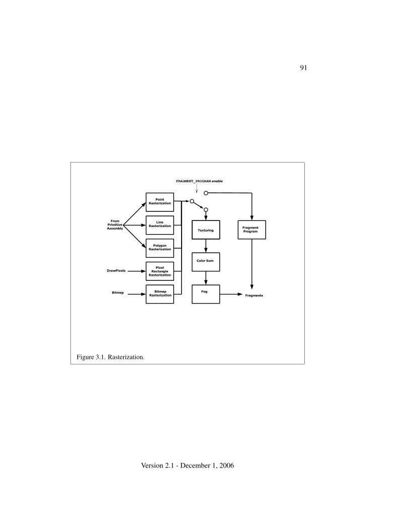
91
PointRasterization
PolygonRasterization
LineRasterization
BitmapRasterization
PixelRectangle
Rasterization
Fog
Color Sum
TexturingFragmentProgram
FromPrimitiveAssembly
DrawPixels
BitmapFragments
FRAGMENT_PROGRAM enable
Figure 3.1. Rasterization.
Version 2.1 - December 1, 2006
92 CHAPTER 3. RASTERIZATION
Several factors affect rasterization. Lines and polygons may be stippled. Pointsmay be given differing diameters and line segments differing widths. A point, linesegment, or polygon may be antialiased.
3.1 Invariance
Consider a primitive p′ obtained by translating a primitive p through an offset (x, y)in window coordinates, where x and y are integers. As long as neither p′ nor p isclipped, it must be the case that each fragment f ′ produced from p′ is identical toa corresponding fragment f from p except that the center of f ′ is offset by (x, y)from the center of f .
3.2 Antialiasing
Antialiasing of a point, line, or polygon is effected in one of two ways dependingon whether the GL is in RGBA or color index mode.
In RGBA mode, the R, G, and B values of the rasterized fragment are leftunaffected, but the A value is multiplied by a floating-point value in the range[0, 1] that describes a fragment’s screen pixel coverage. The per-fragment stage ofthe GL can be set up to use the A value to blend the incoming fragment with thecorresponding pixel already present in the framebuffer.
In color index mode, the least significant b bits (to the left of the binary point)of the color index are used for antialiasing; b = min{4,m}, where m is the numberof bits in the color index portion of the framebuffer. The antialiasing process setsthese b bits based on the fragment’s coverage value: the bits are set to zero for nocoverage and to all ones for complete coverage.
The details of how antialiased fragment coverage values are computed are dif-ficult to specify in general. The reason is that high-quality antialiasing may takeinto account perceptual issues as well as characteristics of the monitor on whichthe contents of the framebuffer are displayed. Such details cannot be addressedwithin the scope of this document. Further, the coverage value computed for afragment of some primitive may depend on the primitive’s relationship to a num-ber of grid squares neighboring the one corresponding to the fragment, and not juston the fragment’s grid square. Another consideration is that accurate calculationof coverage values may be computationally expensive; consequently we allow agiven GL implementation to approximate true coverage values by using a fast butnot entirely accurate coverage computation.
In light of these considerations, we chose to specify the behavior of exact an-tialiasing in the prototypical case that each displayed pixel is a perfect square of
Version 2.1 - December 1, 2006
3.2. ANTIALIASING 93
uniform intensity. The square is called a fragment square and has lower left corner(x, y) and upper right corner (x+1, y+1). We recognize that this simple box filtermay not produce the most favorable antialiasing results, but it provides a simple,well-defined model.
A GL implementation may use other methods to perform antialiasing, subjectto the following conditions:
1. If f1 and f2 are two fragments, and the portion of f1 covered by some prim-itive is a subset of the corresponding portion of f2 covered by the primitive,then the coverage computed for f1 must be less than or equal to that com-puted for f2.
2. The coverage computation for a fragment f must be local: it may dependonly on f ’s relationship to the boundary of the primitive being rasterized. Itmay not depend on f ’s x and y coordinates.
Another property that is desirable, but not required, is:
3. The sum of the coverage values for all fragments produced by rasterizing aparticular primitive must be constant, independent of any rigid motions inwindow coordinates, as long as none of those fragments lies along windowedges.
In some implementations, varying degrees of antialiasing quality may be obtainedby providing GL hints (section 5.6), allowing a user to make an image qualityversus speed tradeoff.
3.2.1 Multisampling
Multisampling is a mechanism to antialias all GL primitives: points, lines, poly-gons, bitmaps, and images. The technique is to sample all primitives multiple timesat each pixel. The color sample values are resolved to a single, displayable coloreach time a pixel is updated, so the antialiasing appears to be automatic at theapplication level. Because each sample includes color, depth, and stencil informa-tion, the color (including texture operation), depth, and stencil functions performequivalently to the single-sample mode.
An additional buffer, called the multisample buffer, is added to the framebuffer.Pixel sample values, including color, depth, and stencil values, are stored in thisbuffer. Samples contain separate color values for each fragment color. Whenthe framebuffer includes a multisample buffer, it does not include depth or sten-cil buffers, even if the multisample buffer does not store depth or stencil values.
Version 2.1 - December 1, 2006
94 CHAPTER 3. RASTERIZATION
Color buffers (left, right, front, back, and aux) do coexist with the multisamplebuffer, however.
Multisample antialiasing is most valuable for rendering polygons, because itrequires no sorting for hidden surface elimination, and it correctly handles adjacentpolygons, object silhouettes, and even intersecting polygons. If only points orlines are being rendered, the “smooth” antialiasing mechanism provided by thebase GL may result in a higher quality image. This mechanism is designed toallow multisample and smooth antialiasing techniques to be alternated during therendering of a single scene.
If the value of SAMPLE BUFFERS is one, the rasterization of all primi-tives is changed, and is referred to as multisample rasterization. Otherwise,primitive rasterization is referred to as single-sample rasterization. The valueof SAMPLE BUFFERS is queried by calling GetIntegerv with pname set toSAMPLE BUFFERS.
During multisample rendering the contents of a pixel fragment are changedin two ways. First, each fragment includes a coverage value with SAMPLES bits.The value of SAMPLES is an implementation-dependent constant, and is queried bycalling GetIntegerv with pname set to SAMPLES.
Second, each fragment includes SAMPLES depth values, color values, and setsof texture coordinates, instead of the single depth value, color value, and set oftexture coordinates that is maintained in single-sample rendering mode. An imple-mentation may choose to assign the same color value and the same set of texturecoordinates to more than one sample. The location for evaluating the color valueand the set of texture coordinates can be anywhere within the pixel including thefragment center or any of the sample locations. The color value and the set of tex-ture coordinates need not be evaluated at the same location. Each pixel fragmentthus consists of integer x and y grid coordinates, SAMPLES color and depth values,SAMPLES sets of texture coordinates, and a coverage value with a maximum ofSAMPLES bits.
Multisample rasterization is enabled or disabled by calling Enable or Disablewith the symbolic constant MULTISAMPLE.
If MULTISAMPLE is disabled, multisample rasterization of all primitives isequivalent to single-sample (fragment-center) rasterization, except that the frag-ment coverage value is set to full coverage. The color and depth values and thesets of texture coordinates may all be set to the values that would have been as-signed by single-sample rasterization, or they may be assigned as described belowfor multisample rasterization.
If MULTISAMPLE is enabled, multisample rasterization of all primitives differssubstantially from single-sample rasterization. It is understood that each pixel inthe framebuffer has SAMPLES locations associated with it. These locations are
Version 2.1 - December 1, 2006

3.3. POINTS 95
exact positions, rather than regions or areas, and each is referred to as a samplepoint. The sample points associated with a pixel may be located inside or outsideof the unit square that is considered to bound the pixel. Furthermore, the relativelocations of sample points may be identical for each pixel in the framebuffer, orthey may differ.
If the sample locations differ per pixel, they should be aligned to window, notscreen, boundaries. Otherwise rendering results will be window-position specific.The invariance requirement described in section 3.1 is relaxed for all multisamplerasterization, because the sample locations may be a function of pixel location.
It is not possible to query the actual sample locations of a pixel.
3.3 Points
If a vertex shader is not active, then the rasterization of points is controlled with
void PointSize( float size );
size specifies the requested size of a point. The default value is 1.0. A value lessthan or equal to zero results in the error INVALID VALUE.
The requested point size is multiplied with a distance attenuation factor,clamped to a specified point size range, and further clamped to the implementation-dependent point size range to produce the derived point size:
derived size = clamp
(size ∗
√(1
a + b ∗ d + c ∗ d2
))
where d is the eye-coordinate distance from the eye, (0, 0, 0, 1) in eye coordinates,to the vertex, and a, b, and c are distance attenuation function coefficients.
If multisampling is not enabled, the derived size is passed on to rasterization asthe point width.
If a vertex shader is active and vertex program point size mode is enabled,then the derived point size is taken from the (potentially clipped) shader builtingl PointSize and clamped to the implementation-dependent point size range. Ifthe value written to gl PointSize is less than or equal to zero, results are unde-fined. If a vertex shader is active and vertex program point size mode is disabled,then the derived point size is taken from the point size state as specified by thePointSize command. In this case no distance attenuation is performed. Vertex pro-gram point size mode is enabled and disabled by calling Enable or Disable withthe symbolic value VERTEX PROGRAM POINT SIZE.
Version 2.1 - December 1, 2006
96 CHAPTER 3. RASTERIZATION
If multisampling is enabled, an implementation may optionally fade the pointalpha (see section 3.13) instead of allowing the point width to go below a giventhreshold. In this case, the width of the rasterized point is
width =
{derived size derived size ≥ thresholdthreshold otherwise
(3.1)
and the fade factor is computed as follows:
fade =
1 derived size ≥ threshold(derived size
threshold
)2otherwise
(3.2)
The distance attenuation function coefficients a, b, and c, the bounds of the firstpoint size range clamp, and the point fade threshold, are specified with
void PointParameter{if}( enum pname, T param );void PointParameter{if}v( enum pname, const T params );
If pname is POINT SIZE MIN or POINT SIZE MAX, then param speci-fies, or params points to the lower or upper bound respectively to whichthe derived point size is clamped. If the lower bound is greater thanthe upper bound, the point size after clamping is undefined. If pname isPOINT DISTANCE ATTENUATION, then params points to the coefficients a, b,and c. If pname is POINT FADE THRESHOLD SIZE, then param specifies,or params points to the point fade threshold. Values of POINT SIZE MIN,POINT SIZE MAX, or POINT FADE THRESHOLD SIZE less than zero result in theerror INVALID VALUE.
Point antialiasing is enabled or disabled by calling Enable or Disable with thesymbolic constant POINT SMOOTH. The default state is for point antialiasing to bedisabled.
Point sprites are enabled or disabled by calling Enable or Disable with thesymbolic constant POINT SPRITE. The default state is for point sprites to be dis-abled. When point sprites are enabled, the state of the point antialiasing enable isignored.
The point sprite texture coordinate replacement mode is set with one of the Tex-Env* commands described in section 3.8.13, where target is POINT SPRITE andpname is COORD REPLACE. The possible values for param are FALSE and TRUE.The default value for each texture coordinate set is for point sprite texture coordi-nate replacement to be disabled.
The point sprite texture coordinate origin is set with the PointParame-ter* commands where pname is POINT SPRITE COORD ORIGIN and param isLOWER LEFT or UPPER LEFT. The default value is UPPER LEFT.
Version 2.1 - December 1, 2006
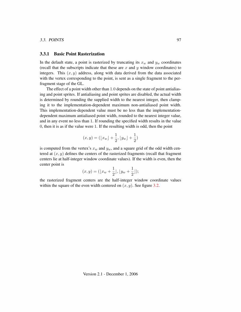
3.3. POINTS 97
3.3.1 Basic Point Rasterization
In the default state, a point is rasterized by truncating its xw and yw coordinates(recall that the subscripts indicate that these are x and y window coordinates) tointegers. This (x, y) address, along with data derived from the data associatedwith the vertex corresponding to the point, is sent as a single fragment to the per-fragment stage of the GL.
The effect of a point width other than 1.0 depends on the state of point antialias-ing and point sprites. If antialiasing and point sprites are disabled, the actual widthis determined by rounding the supplied width to the nearest integer, then clamp-ing it to the implementation-dependent maximum non-antialiased point width.This implementation-dependent value must be no less than the implementation-dependent maximum antialiased point width, rounded to the nearest integer value,and in any event no less than 1. If rounding the specified width results in the value0, then it is as if the value were 1. If the resulting width is odd, then the point
(x, y) = (bxwc+12, bywc+
12)
is computed from the vertex’s xw and yw, and a square grid of the odd width cen-tered at (x, y) defines the centers of the rasterized fragments (recall that fragmentcenters lie at half-integer window coordinate values). If the width is even, then thecenter point is
(x, y) = (bxw +12c, byw +
12c);
the rasterized fragment centers are the half-integer window coordinate valueswithin the square of the even width centered on (x, y). See figure 3.2.
Version 2.1 - December 1, 2006
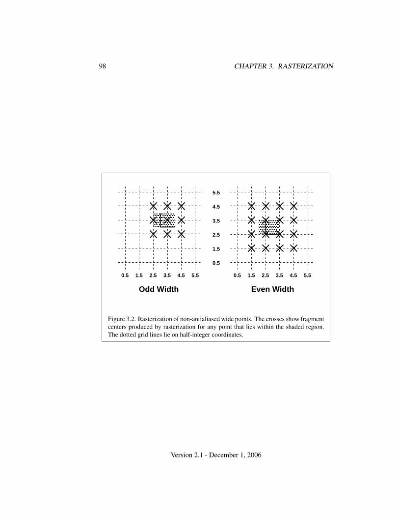
98 CHAPTER 3. RASTERIZATION
� � �� � �
� � �� � �
Odd Width Even Width
3.5 4.5 5.52.51.5 3.5 4.5 5.52.51.5
1.5
2.5
3.5
4.5
0.50.5
0.5
5.5
Figure 3.2. Rasterization of non-antialiased wide points. The crosses show fragmentcenters produced by rasterization for any point that lies within the shaded region.The dotted grid lines lie on half-integer coordinates.
Version 2.1 - December 1, 2006
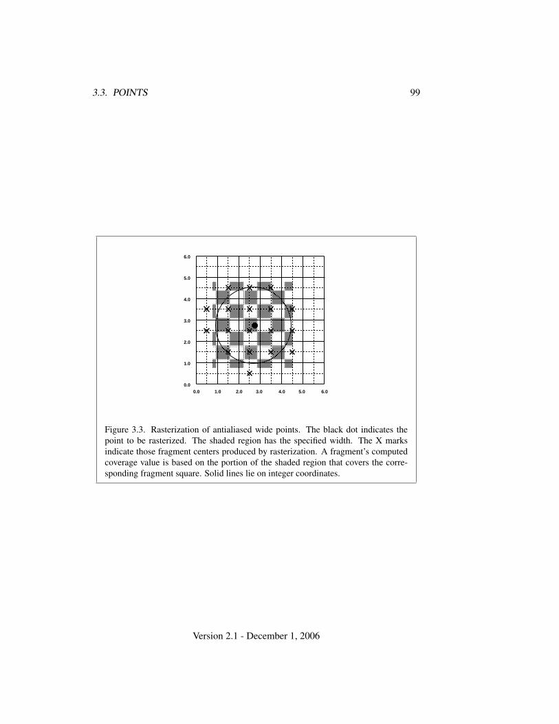
3.3. POINTS 99
� � � � � � � � � � � � � � �� � � � � � � � � � � � � � �� � � � � � � � � � � � � � �� � � � � � � � � � � � � � �� � � � � � � � � � � � � � �� � � � � � � � � � � � � � �� � � � � � � � � � � � � � �� � � � � � � � � � � � � � �� � � � � � � � � � � � � � �� � � � � � � � � � � � � � �� � � � � � � � � � � � � � �� � � � � � � � � � � � � � �� � � � � � � � � � � � � � �� � � � � � � � � � � � � � �� � � � � � � � � � � � � � �� � � � � � � � � � � � � � �
1.00.0 3.02.0 5.04.0 6.00.0
1.0
2.0
3.0
4.0
5.0
6.0
Figure 3.3. Rasterization of antialiased wide points. The black dot indicates thepoint to be rasterized. The shaded region has the specified width. The X marksindicate those fragment centers produced by rasterization. A fragment’s computedcoverage value is based on the portion of the shaded region that covers the corre-sponding fragment square. Solid lines lie on integer coordinates.
Version 2.1 - December 1, 2006
100 CHAPTER 3. RASTERIZATION
All fragments produced in rasterizing a non-antialiased point are assigned thesame associated data, which are those of the vertex corresponding to the point.
If antialiasing is enabled and point sprites are disabled, then point rasterizationproduces a fragment for each fragment square that intersects the region lying withinthe circle having diameter equal to the current point width and centered at thepoint’s (xw, yw) (figure 3.3). The coverage value for each fragment is the windowcoordinate area of the intersection of the circular region with the correspondingfragment square (but see section 3.2). This value is saved and used in the finalstep of rasterization (section 3.12). The data associated with each fragment areotherwise the data associated with the point being rasterized.
Not all widths need be supported when point antialiasing is on, but the width1.0 must be provided. If an unsupported width is requested, the nearest supportedwidth is used instead. The range of supported widths and the width of evenly-spaced gradations within that range are implementation dependent. The range andgradations may be obtained using the query mechanism described in chapter 6. If,for instance, the width range is from 0.1 to 2.0 and the gradation width is 0.1, thenthe widths 0.1, 0.2, . . . , 1.9, 2.0 are supported.
If point sprites are enabled, then point rasterization produces a fragment foreach framebuffer pixel whose center lies inside a square centered at the point’s(xw, yw), with side length equal to the current point size.
All fragments produced in rasterizing a point sprite are assigned the same as-sociated data, which are those of the vertex corresponding to the point. How-ever, for each texture coordinate set where COORD REPLACE is TRUE, thesetexture coordinates are replaced with point sprite texture coordinates. The scoordinate varies from 0 to 1 across the point horizontally left-to-right. IfPOINT SPRITE COORD ORIGIN is LOWER LEFT, the t coordinate varies from 0to 1 vertically bottom-to-top. Otherwise if the point sprite texture coordinate ori-gin is UPPER LEFT, the t coordinate varies from 0 to 1 vertically top-to-bottom.The r and q coordinates are replaced with the constants 0 and 1, respectively.
The following formula is used to evaluate the s and t coordinates:
s =12
+
(xf + 1
2 − xw
)size
(3.3)
t =
12 + (yf+ 1
2−yw)
size , POINT SPRITE COORD ORIGIN = LOWER LEFT
12 −
(yf+ 12−yw)
size , POINT SPRITE COORD ORIGIN = UPPER LEFT(3.4)
where size is the point’s size, xf and yf are the (integral) window coordinates of
Version 2.1 - December 1, 2006
3.4. LINE SEGMENTS 101
the fragment, and xw and yw are the exact, unrounded window coordinates of thevertex for the point.
The widths supported for point sprites must be a superset of those supportedfor antialiased points. There is no requirement that these widths must be equallyspaced. If an unsupported width is requested, the nearest supported width is usedinstead.
3.3.2 Point Rasterization State
The state required to control point rasterization consists of the floating-point pointwidth, three floating-point values specifying the minimum and maximum point sizeand the point fade threshold size, three floating-point values specifying the distanceattenuation coefficients, a bit indicating whether or not antialiasing is enabled, a bitfor the point sprite texture coordinate replacement mode for each texture coordinateset, and a bit for the point sprite texture coordinate origin.
3.3.3 Point Multisample Rasterization
If MULTISAMPLE is enabled, and the value of SAMPLE BUFFERS is one, then pointsare rasterized using the following algorithm, regardless of whether point antialias-ing (POINT SMOOTH) is enabled or disabled. Point rasterization produces a frag-ment for each framebuffer pixel with one or more sample points that intersect aregion centered at the point’s (xw, yw). This region is a circle having diameterequal to the current point width if POINT SPRITE is disabled, or a square withside equal to the current point width if POINT SPRITE is enabled. Coverage bitsthat correspond to sample points that intersect the region are 1, other coverage bitsare 0. All data associated with each sample for the fragment are the data associ-ated with the point being rasterized, with the exception of texture coordinates whenPOINT SPRITE is enabled; these texture coordinates are computed as described insection 3.3.
Point size range and number of gradations are equivalent to those supportedfor antialiased points when POINT SPRITE is disabled. The set of point sizessupported is equivalent to those for point sprites without multisample whenPOINT SPRITE is enabled.
3.4 Line Segments
A line segment results from a line strip Begin/End object, a line loop, or a se-ries of separate line segments. Line segment rasterization is controlled by severalvariables. Line width, which may be set by calling
Version 2.1 - December 1, 2006
102 CHAPTER 3. RASTERIZATION
void LineWidth( float width );
with an appropriate positive floating-point width, controls the width of rasterizedline segments. The default width is 1.0. Values less than or equal to 0.0 generatethe error INVALID VALUE. Antialiasing is controlled with Enable and Disableusing the symbolic constant LINE SMOOTH. Finally, line segments may be stippled.Stippling is controlled by a GL command that sets a stipple pattern (see below).
3.4.1 Basic Line Segment Rasterization
Line segment rasterization begins by characterizing the segment as either x-majoror y-major. x-major line segments have slope in the closed interval [−1, 1]; allother line segments are y-major (slope is determined by the segment’s endpoints).We shall specify rasterization only for x-major segments except in cases where themodifications for y-major segments are not self-evident.
Ideally, the GL uses a “diamond-exit” rule to determine those fragments thatare produced by rasterizing a line segment. For each fragment f with center at win-dow coordinates xf and yf , define a diamond-shaped region that is the intersectionof four half planes:
Rf = { (x, y) | |x− xf |+ |y − yf | < 1/2.}
Essentially, a line segment starting at pa and ending at pb produces those frag-ments f for which the segment intersects Rf , except if pb is contained in Rf . Seefigure 3.4.
To avoid difficulties when an endpoint lies on a boundary of Rf we (in princi-ple) perturb the supplied endpoints by a tiny amount. Let pa and pb have windowcoordinates (xa, ya) and (xb, yb), respectively. Obtain the perturbed endpoints p′agiven by (xa, ya) − (ε, ε2) and p′b given by (xb, yb) − (ε, ε2). Rasterizing the linesegment starting at pa and ending at pb produces those fragments f for which thesegment starting at p′a and ending on p′b intersects Rf , except if p′b is contained inRf . ε is chosen to be so small that rasterizing the line segment produces the samefragments when δ is substituted for ε for any 0 < δ ≤ ε.
When pa and pb lie on fragment centers, this characterization of fragmentsreduces to Bresenham’s algorithm with one modification: lines produced in thisdescription are “half-open,” meaning that the final fragment (corresponding to pb)is not drawn. This means that when rasterizing a series of connected line segments,shared endpoints will be produced only once rather than twice (as would occur withBresenham’s algorithm).
Because the initial and final conditions of the diamond-exit rule may be difficultto implement, other line segment rasterization algorithms are allowed, subject tothe following rules:
Version 2.1 - December 1, 2006
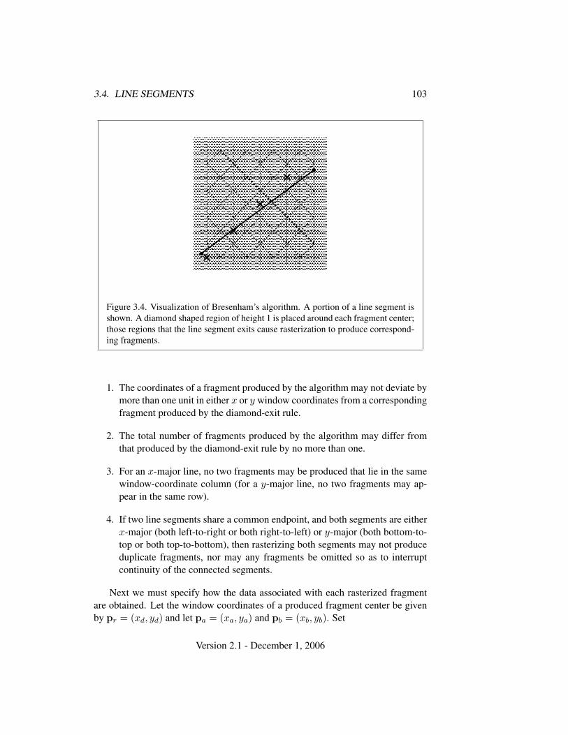
3.4. LINE SEGMENTS 103
� � � � �� � � � �� � � � �� � � � �
� � � � �� � � � �� � � � �� � � � �
� � � � �� � � � �� � � � �� � � � �
� � � � �� � � � �� � � � �� � � � �
� � � � �� � � � �� � � � �� � � � �
� � � � �� � � � �� � � � �� � � � �� � � � �� � � � �� � � � �� � � � �� � � � �� � � � �� � � � �� � � � �� � � � �� � � � �� � � � �� � � � �
� � � � �� � � � �� � � � �� � � � �� � � � �� � � � �� � � � �� � � � �
� � � � �� � � � �� � � � �� � � � �
� � � � �� � � � �� � � � �� � � � �� � � � �� � � � �� � � � �� � � � �� � � � �� � � � �� � � � �� � � � �� � � � �� � � � �� � � � �� � � � �� � � � �� � � � �� � � � �� � � � �
� � � � �� � � � �� � � � �� � � � �� � � � �� � � � �� � � � �� � � � �� � � � �� � � � �� � � � �� � � � �� � � � �� � � � �� � � � �� � � � �� � � � �� � � � �� � � � �� � � � �
Figure 3.4. Visualization of Bresenham’s algorithm. A portion of a line segment isshown. A diamond shaped region of height 1 is placed around each fragment center;those regions that the line segment exits cause rasterization to produce correspond-ing fragments.
1. The coordinates of a fragment produced by the algorithm may not deviate bymore than one unit in either x or y window coordinates from a correspondingfragment produced by the diamond-exit rule.
2. The total number of fragments produced by the algorithm may differ fromthat produced by the diamond-exit rule by no more than one.
3. For an x-major line, no two fragments may be produced that lie in the samewindow-coordinate column (for a y-major line, no two fragments may ap-pear in the same row).
4. If two line segments share a common endpoint, and both segments are eitherx-major (both left-to-right or both right-to-left) or y-major (both bottom-to-top or both top-to-bottom), then rasterizing both segments may not produceduplicate fragments, nor may any fragments be omitted so as to interruptcontinuity of the connected segments.
Next we must specify how the data associated with each rasterized fragmentare obtained. Let the window coordinates of a produced fragment center be givenby pr = (xd, yd) and let pa = (xa, ya) and pb = (xb, yb). Set
Version 2.1 - December 1, 2006
104 CHAPTER 3. RASTERIZATION
t =(pr − pa) · (pb − pa)
‖pb − pa‖2. (3.5)
(Note that t = 0 at pa and t = 1 at pb.) The value of an associated datum f forthe fragment, whether it be primary or secondary R, G, B, or A (in RGBA mode)or a color index (in color index mode), the fog coordinate, an s, t, r, or q texturecoordinate, or the clip w coordinate, is found as
f =(1− t)fa/wa + tfb/wb
(1− t)/wa + t/wb(3.6)
where fa and fb are the data associated with the starting and ending endpoints ofthe segment, respectively; wa and wb are the clip w coordinates of the starting andending endpoints of the segments, respectively. However, depth values for linesmust be interpolated by
z = (1− t)za + tzb (3.7)
where za and zb are the depth values of the starting and ending endpoints of thesegment, respectively.
3.4.2 Other Line Segment Features
We have just described the rasterization of non-antialiased line segments of widthone using the default line stipple of FFFF16. We now describe the rasterizationof line segments for general values of the line segment rasterization parameters.
Line Stipple
The command
void LineStipple( int factor, ushort pattern );
defines a line stipple. pattern is an unsigned short integer. The line stipple is takenfrom the lowest order 16 bits of pattern. It determines those fragments that areto be drawn when the line is rasterized. factor is a count that is used to modifythe effective line stipple by causing each bit in line stipple to be used factor times.factor is clamped to the range [1, 256]. Line stippling may be enabled or disabledusing Enable or Disable with the constant LINE STIPPLE. When disabled, it is asif the line stipple has its default value.
Line stippling masks certain fragments that are produced by rasterization sothat they are not sent to the per-fragment stage of the GL. The masking is achieved
Version 2.1 - December 1, 2006
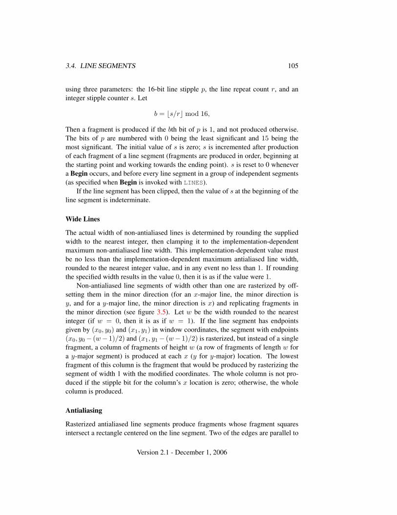
3.4. LINE SEGMENTS 105
using three parameters: the 16-bit line stipple p, the line repeat count r, and aninteger stipple counter s. Let
b = bs/rc mod 16,
Then a fragment is produced if the bth bit of p is 1, and not produced otherwise.The bits of p are numbered with 0 being the least significant and 15 being themost significant. The initial value of s is zero; s is incremented after productionof each fragment of a line segment (fragments are produced in order, beginning atthe starting point and working towards the ending point). s is reset to 0 whenevera Begin occurs, and before every line segment in a group of independent segments(as specified when Begin is invoked with LINES).
If the line segment has been clipped, then the value of s at the beginning of theline segment is indeterminate.
Wide Lines
The actual width of non-antialiased lines is determined by rounding the suppliedwidth to the nearest integer, then clamping it to the implementation-dependentmaximum non-antialiased line width. This implementation-dependent value mustbe no less than the implementation-dependent maximum antialiased line width,rounded to the nearest integer value, and in any event no less than 1. If roundingthe specified width results in the value 0, then it is as if the value were 1.
Non-antialiased line segments of width other than one are rasterized by off-setting them in the minor direction (for an x-major line, the minor direction isy, and for a y-major line, the minor direction is x) and replicating fragments inthe minor direction (see figure 3.5). Let w be the width rounded to the nearestinteger (if w = 0, then it is as if w = 1). If the line segment has endpointsgiven by (x0, y0) and (x1, y1) in window coordinates, the segment with endpoints(x0, y0− (w− 1)/2) and (x1, y1− (w− 1)/2) is rasterized, but instead of a singlefragment, a column of fragments of height w (a row of fragments of length w fora y-major segment) is produced at each x (y for y-major) location. The lowestfragment of this column is the fragment that would be produced by rasterizing thesegment of width 1 with the modified coordinates. The whole column is not pro-duced if the stipple bit for the column’s x location is zero; otherwise, the wholecolumn is produced.
Antialiasing
Rasterized antialiased line segments produce fragments whose fragment squaresintersect a rectangle centered on the line segment. Two of the edges are parallel to
Version 2.1 - December 1, 2006

106 CHAPTER 3. RASTERIZATION
width = 2 width = 3
Figure 3.5. Rasterization of non-antialiased wide lines. x-major line segments areshown. The heavy line segment is the one specified to be rasterized; the light seg-ment is the offset segment used for rasterization. x marks indicate the fragmentcenters produced by rasterization.
the specified line segment; each is at a distance of one-half the current width fromthat segment: one above the segment and one below it. The other two edges passthrough the line endpoints and are perpendicular to the direction of the specifiedline segment. Coverage values are computed for each fragment by computing thearea of the intersection of the rectangle with the fragment square (see figure 3.6;see also section 3.2). Equation 3.6 is used to compute associated data values just aswith non-antialiased lines; equation 3.5 is used to find the value of t for each frag-ment whose square is intersected by the line segment’s rectangle. Not all widthsneed be supported for line segment antialiasing, but width 1.0 antialiased segmentsmust be provided. As with the point width, a GL implementation may be queriedfor the range and number of gradations of available antialiased line widths.
For purposes of antialiasing, a stippled line is considered to be a sequence ofcontiguous rectangles centered on the line segment. Each rectangle has width equalto the current line width and length equal to 1 pixel (except the last, which may beshorter). These rectangles are numbered from 0 to n, starting with the rectangleincident on the starting endpoint of the segment. Each of these rectangles is ei-ther eliminated or produced according to the procedure given under Line Stipple,above, where “fragment” is replaced with “rectangle.” Each rectangle so produced
Version 2.1 - December 1, 2006
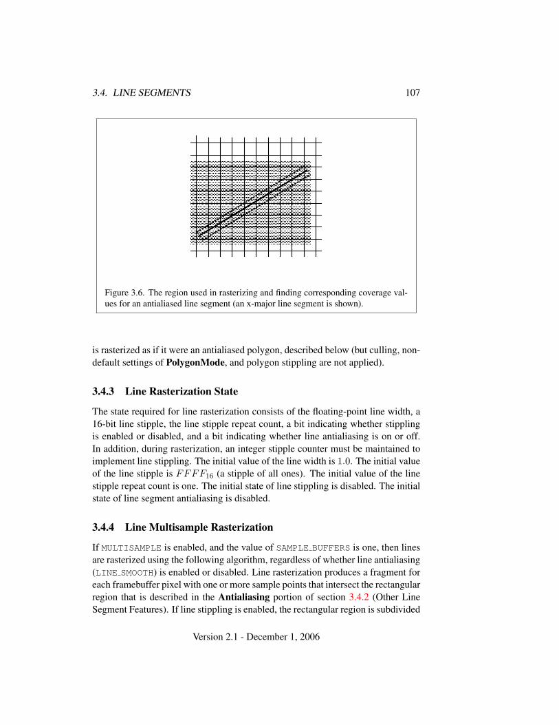
3.4. LINE SEGMENTS 107
� � � � � � � � � � � � � � � � � � � �� � � � � � � � � � � � � � � � � � � �� � � � � � � � � � � � � � � � � � � �� � � � � � � � � � � � � � � � � � � �� � � � � � � � � � � � � � � � � � � �� � � � � � � � � � � � � � � � � � � �� � � � � � � � � � � � � � � � � � � �� � � � � � � � � � � � � � � � � � � �� � � � � � � � � � � � � � � � � � � �� � � � � � � � � � � � � � � � � � � �� � � � � � � � � � � � � � � � � � � �� � � � � � � � � � � � � � � � � � � �� � � � � � � � � � � � � � � � � � � �� � � � � � � � � � � � � � � � � � � �
Figure 3.6. The region used in rasterizing and finding corresponding coverage val-ues for an antialiased line segment (an x-major line segment is shown).
is rasterized as if it were an antialiased polygon, described below (but culling, non-default settings of PolygonMode, and polygon stippling are not applied).
3.4.3 Line Rasterization State
The state required for line rasterization consists of the floating-point line width, a16-bit line stipple, the line stipple repeat count, a bit indicating whether stipplingis enabled or disabled, and a bit indicating whether line antialiasing is on or off.In addition, during rasterization, an integer stipple counter must be maintained toimplement line stippling. The initial value of the line width is 1.0. The initial valueof the line stipple is FFFF16 (a stipple of all ones). The initial value of the linestipple repeat count is one. The initial state of line stippling is disabled. The initialstate of line segment antialiasing is disabled.
3.4.4 Line Multisample Rasterization
If MULTISAMPLE is enabled, and the value of SAMPLE BUFFERS is one, then linesare rasterized using the following algorithm, regardless of whether line antialiasing(LINE SMOOTH) is enabled or disabled. Line rasterization produces a fragment foreach framebuffer pixel with one or more sample points that intersect the rectangularregion that is described in the Antialiasing portion of section 3.4.2 (Other LineSegment Features). If line stippling is enabled, the rectangular region is subdivided
Version 2.1 - December 1, 2006
108 CHAPTER 3. RASTERIZATION
into adjacent unit-length rectangles, with some rectangles eliminated according tothe procedure given in section 3.4.2, where “fragment” is replaced by “rectangle”.
Coverage bits that correspond to sample points that intersect a retained rectan-gle are 1, other coverage bits are 0. Each color, depth, and set of texture coordinatesis produced by substituting the corresponding sample location into equation 3.5,then using the result to evaluate equation 3.7. An implementation may choose toassign the same color value and the same set of texture coordinates to more thanone sample by evaluating equation 3.5 at any location within the pixel includingthe fragment center or any one of the sample locations, then substituting into equa-tion 3.6. The color value and the set of texture coordinates need not be evaluatedat the same location.
Line width range and number of gradations are equivalent to those supportedfor antialiased lines.
3.5 Polygons
A polygon results from a polygon Begin/End object, a triangle resulting from atriangle strip, triangle fan, or series of separate triangles, or a quadrilateral arisingfrom a quadrilateral strip, series of separate quadrilaterals, or a Rect command.Like points and line segments, polygon rasterization is controlled by several vari-ables. Polygon antialiasing is controlled with Enable and Disable with the sym-bolic constant POLYGON SMOOTH. The analog to line segment stippling for poly-gons is polygon stippling, described below.
3.5.1 Basic Polygon Rasterization
The first step of polygon rasterization is to determine if the polygon is back facingor front facing. This determination is made by examining the sign of the area com-puted by equation 2.6 of section 2.14.1 (including the possible reversal of this signas indicated by the last call to FrontFace). If this sign is positive, the polygon isfrontfacing; otherwise, it is back facing. This determination is used in conjunctionwith the CullFace enable bit and mode value to decide whether or not a particularpolygon is rasterized. The CullFace mode is set by calling
void CullFace( enum mode );
mode is a symbolic constant: one of FRONT, BACK or FRONT AND BACK. Cullingis enabled or disabled with Enable or Disable using the symbolic constantCULL FACE. Front facing polygons are rasterized if either culling is disabled or
Version 2.1 - December 1, 2006
3.5. POLYGONS 109
the CullFace mode is BACK while back facing polygons are rasterized only if ei-ther culling is disabled or the CullFace mode is FRONT. The initial setting of theCullFace mode is BACK. Initially, culling is disabled.
The rule for determining which fragments are produced by polygon rasteriza-tion is called point sampling. The two-dimensional projection obtained by takingthe x and y window coordinates of the polygon’s vertices is formed. Fragmentcenters that lie inside of this polygon are produced by rasterization. Special treat-ment is given to a fragment whose center lies on a polygon boundary edge. Insuch a case we require that if two polygons lie on either side of a common edge(with identical endpoints) on which a fragment center lies, then exactly one of thepolygons results in the production of the fragment during rasterization.
As for the data associated with each fragment produced by rasterizing a poly-gon, we begin by specifying how these values are produced for fragments in atriangle. Define barycentric coordinates for a triangle. Barycentric coordinates area set of three numbers, a, b, and c, each in the range [0, 1], with a + b + c = 1.These coordinates uniquely specify any point p within the triangle or on the trian-gle’s boundary as
p = apa + bpb + cpc,
where pa, pb, and pc are the vertices of the triangle. a, b, and c can be found as
a =A(ppbpc)A(papbpc)
, b =A(ppapc)A(papbpc)
, c =A(ppapb)A(papbpc)
,
where A(lmn) denotes the area in window coordinates of the triangle with verticesl, m, and n.
Denote an associated datum at pa, pb, or pc as fa, fb, or fc, respectively. Thenthe value f of a datum at a fragment produced by rasterizing a triangle is given by
f =afa/wa + bfb/wb + cfc/wc
a/wa + b/wb + c/wc(3.8)
where wa, wb and wc are the clip w coordinates of pa, pb, and pc, respectively.a, b, and c are the barycentric coordinates of the fragment for which the data areproduced. a, b, and c must correspond precisely to the exact coordinates of thecenter of the fragment. Another way of saying this is that the data associated witha fragment must be sampled at the fragment’s center. However, depth values forpolygons must be interpolated by
z = aza + bzb + czc,
where za, zb, and zc are the depth values of pa, pb, and pc, respectively.
Version 2.1 - December 1, 2006
110 CHAPTER 3. RASTERIZATION
For a polygon with more than three edges, we require only that a convex com-bination of the values of the datum at the polygon’s vertices can be used to obtainthe value assigned to each fragment produced by the rasterization algorithm. Thatis, it must be the case that at every fragment
f =n∑
i=1
aifi
where n is the number of vertices in the polygon, fi is the value of the f at vertexi; for each i 0 ≤ ai ≤ 1 and
∑ni=1 ai = 1. The values of the ai may differ from
fragment to fragment, but at vertex i, aj = 0, j 6= i and ai = 1.One algorithm that achieves the required behavior is to triangulate a polygon
(without adding any vertices) and then treat each triangle individually as alreadydiscussed. A scan-line rasterizer that linearly interpolates data along each edgeand then linearly interpolates data across each horizontal span from edge to edgealso satisfies the restrictions (in this case, the numerator and denominator of equa-tion 3.8 should be iterated independently and a division performed for each frag-ment).
3.5.2 Stippling
Polygon stippling works much the same way as line stippling, masking out certainfragments produced by rasterization so that they are not sent to the next stage ofthe GL. This is the case regardless of the state of polygon antialiasing. Stippling iscontrolled with
void PolygonStipple( ubyte *pattern );
pattern is a pointer to memory into which a 32× 32 pattern is packed. The patternis unpacked from memory according to the procedure given in section 3.6.4 forDrawPixels; it is as if the height and width passed to that command were both equalto 32, the type were BITMAP, and the format were COLOR INDEX. The unpackedvalues (before any conversion or arithmetic would have been performed) form astipple pattern of zeros and ones.
If xw and yw are the window coordinates of a rasterized polygon fragment,then that fragment is sent to the next stage of the GL if and only if the bit of thepattern (xw mod 32, yw mod 32) is 1.
Polygon stippling may be enabled or disabled with Enable or Disable usingthe constant POLYGON STIPPLE. When disabled, it is as if the stipple pattern wereall ones.
Version 2.1 - December 1, 2006
3.5. POLYGONS 111
3.5.3 Antialiasing
Polygon antialiasing rasterizes a polygon by producing a fragment wherever theinterior of the polygon intersects that fragment’s square. A coverage value is com-puted at each such fragment, and this value is saved to be applied as describedin section 3.12. An associated datum is assigned to a fragment by integrating thedatum’s value over the region of the intersection of the fragment square with thepolygon’s interior and dividing this integrated value by the area of the intersection.For a fragment square lying entirely within the polygon, the value of a datum at thefragment’s center may be used instead of integrating the value across the fragment.
Polygon stippling operates in the same way whether polygon antialiasing isenabled or not. The polygon point sampling rule defined in section 3.5.1, however,is not enforced for antialiased polygons.
3.5.4 Options Controlling Polygon Rasterization
The interpretation of polygons for rasterization is controlled using
void PolygonMode( enum face, enum mode );
face is one of FRONT, BACK, or FRONT AND BACK, indicating that the rasterizingmethod described by mode replaces the rasterizing method for front facing poly-gons, back facing polygons, or both front and back facing polygons, respectively.mode is one of the symbolic constants POINT, LINE, or FILL. Calling Polygon-Mode with POINT causes certain vertices of a polygon to be treated, for rasteriza-tion purposes, just as if they were enclosed within a Begin(POINT) and End pair.The vertices selected for this treatment are those that have been tagged as having apolygon boundary edge beginning on them (see section 2.6.2). LINE causes edgesthat are tagged as boundary to be rasterized as line segments. (The line stipplecounter is reset at the beginning of the first rasterized edge of the polygon, butnot for subsequent edges.) FILL is the default mode of polygon rasterization, cor-responding to the description in sections 3.5.1, 3.5.2, and 3.5.3. Note that thesemodes affect only the final rasterization of polygons: in particular, a polygon’s ver-tices are lit, and the polygon is clipped and possibly culled before these modes areapplied.
Polygon antialiasing applies only to the FILL state of PolygonMode. ForPOINT or LINE, point antialiasing or line segment antialiasing, respectively, ap-ply.
Version 2.1 - December 1, 2006
112 CHAPTER 3. RASTERIZATION
3.5.5 Depth Offset
The depth values of all fragments generated by the rasterization of a polygon maybe offset by a single value that is computed for that polygon. The function thatdetermines this value is specified by calling
void PolygonOffset( float factor, float units );
factor scales the maximum depth slope of the polygon, and units scales an im-plementation dependent constant that relates to the usable resolution of the depthbuffer. The resulting values are summed to produce the polygon offset value. Bothfactor and units may be either positive or negative.
The maximum depth slope m of a triangle is
m =
√(∂zw
∂xw
)2
+(
∂zw
∂yw
)2
(3.9)
where (xw, yw, zw) is a point on the triangle. m may be approximated as
m = max{∣∣∣∣ ∂zw
∂xw
∣∣∣∣ , ∣∣∣∣∂zw
∂yw
∣∣∣∣} . (3.10)
If the polygon has more than three vertices, one or more values of m may be usedduring rasterization. Each may take any value in the range [min,max], where minand max are the smallest and largest values obtained by evaluating equation 3.9 orequation 3.10 for the triangles formed by all three-vertex combinations.
The minimum resolvable difference r is an implementation constant. It is thesmallest difference in window coordinate z values that is guaranteed to remaindistinct throughout polygon rasterization and in the depth buffer. All pairs of frag-ments generated by the rasterization of two polygons with otherwise identical ver-tices, but zw values that differ by r, will have distinct depth values.
The offset value o for a polygon is
o = m ∗ factor + r ∗ units. (3.11)
m is computed as described above, as a function of depth values in the range [0,1],and o is applied to depth values in the same range.
Boolean state values POLYGON OFFSET POINT, POLYGON OFFSET LINE, andPOLYGON OFFSET FILL determine whether o is applied during the rasterizationof polygons in POINT, LINE, and FILL modes. These boolean state values areenabled and disabled as argument values to the commands Enable and Disable. IfPOLYGON OFFSET POINT is enabled, o is added to the depth value of each frag-ment produced by the rasterization of a polygon in POINT mode. Likewise, if
Version 2.1 - December 1, 2006
3.5. POLYGONS 113
POLYGON OFFSET LINE or POLYGON OFFSET FILL is enabled, o is added to thedepth value of each fragment produced by the rasterization of a polygon in LINE
or FILL modes, respectively.Fragment depth values are always limited to the range [0,1], either by clamping
after offset addition is performed (preferred), or by clamping the vertex values usedin the rasterization of the polygon.
3.5.6 Polygon Multisample Rasterization
If MULTISAMPLE is enabled and the value of SAMPLE BUFFERS is one, then poly-gons are rasterized using the following algorithm, regardless of whether polygonantialiasing (POLYGON SMOOTH) is enabled or disabled. Polygon rasterization pro-duces a fragment for each framebuffer pixel with one or more sample points thatsatisfy the point sampling criteria described in section 3.5.1, including the specialtreatment for sample points that lie on a polygon boundary edge. If a polygon isculled, based on its orientation and the CullFace mode, then no fragments are pro-duced during rasterization. Fragments are culled by the polygon stipple just as theyare for aliased and antialiased polygons.
Coverage bits that correspond to sample points that satisfy the point samplingcriteria are 1, other coverage bits are 0. Each color, depth, and set of texture co-ordinates is produced by substituting the corresponding sample location into thebarycentric equations described in section 3.5.1, using the approximation to equa-tion 3.8 that omits w components. An implementation may choose to assign thesame color value and the same set of texture coordinates to more than one sampleby barycentric evaluation using any location with the pixel including the fragmentcenter or one of the sample locations. The color value and the set of texture coor-dinates need not be evaluated at the same location.
The rasterization described above applies only to the FILL state of Polygon-Mode. For POINT and LINE, the rasterizations described in sections 3.3.3 (PointMultisample Rasterization) and 3.4.4 (Line Multisample Rasterization) apply.
3.5.7 Polygon Rasterization State
The state required for polygon rasterization consists of a polygon stipple pattern,whether stippling is enabled or disabled, the current state of polygon antialiasing(enabled or disabled), the current values of the PolygonMode setting for each offront and back facing polygons, whether point, line, and fill mode polygon offsetsare enabled or disabled, and the factor and bias values of the polygon offset equa-tion. The initial stipple pattern is all ones; initially stippling is disabled. The initialsetting of polygon antialiasing is disabled. The initial state for PolygonMode is
Version 2.1 - December 1, 2006
114 CHAPTER 3. RASTERIZATION
FILL for both front and back facing polygons. The initial polygon offset factorand bias values are both 0; initially polygon offset is disabled for all modes.
3.6 Pixel Rectangles
Rectangles of color, depth, and certain other values may be converted to fragmentsusing the DrawPixels command (described in section 3.6.4). Some of the param-eters and operations governing the operation of DrawPixels are shared by Read-Pixels (used to obtain pixel values from the framebuffer) and CopyPixels (used tocopy pixels from one framebuffer location to another); the discussion of ReadPix-els and CopyPixels, however, is deferred until chapter 4 after the framebuffer hasbeen discussed in detail. Nevertheless, we note in this section when parametersand state pertaining to DrawPixels also pertain to ReadPixels or CopyPixels.
A number of parameters control the encoding of pixels in buffer object orclient memory (for reading and writing) and how pixels are processed before beingplaced in or after being read from the framebuffer (for reading, writing, and copy-ing). These parameters are set with three commands: PixelStore, PixelTransfer,and PixelMap.
3.6.1 Pixel Storage Modes and Pixel Buffer Objects
Pixel storage modes affect the operation of DrawPixels and ReadPixels (as well asother commands; see sections 3.5.2, 3.7, and 3.8) when one of these commands isissued. This may differ from the time that the command is executed if the commandis placed in a display list (see section 5.4). Pixel storage modes are set with
void PixelStore{if}( enum pname, T param );
pname is a symbolic constant indicating a parameter to be set, and param is thevalue to set it to. Table 3.1 summarizes the pixel storage parameters, their types,their initial values, and their allowable ranges. Setting a parameter to a value out-side the given range results in the error INVALID VALUE.
The version of PixelStore that takes a floating-point value may be used toset any type of parameter; if the parameter is boolean, then it is set to FALSE ifthe passed value is 0.0 and TRUE otherwise, while if the parameter is an integer,then the passed value is rounded to the nearest integer. The integer version ofthe command may also be used to set any type of parameter; if the parameter isboolean, then it is set to FALSE if the passed value is 0 and TRUE otherwise, whileif the parameter is a floating-point value, then the passed value is converted tofloating-point.
Version 2.1 - December 1, 2006
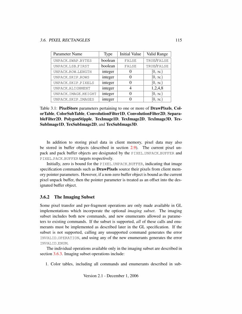
3.6. PIXEL RECTANGLES 115
Parameter Name Type Initial Value Valid RangeUNPACK SWAP BYTES boolean FALSE TRUE/FALSEUNPACK LSB FIRST boolean FALSE TRUE/FALSEUNPACK ROW LENGTH integer 0 [0,∞)UNPACK SKIP ROWS integer 0 [0,∞)UNPACK SKIP PIXELS integer 0 [0,∞)UNPACK ALIGNMENT integer 4 1,2,4,8UNPACK IMAGE HEIGHT integer 0 [0,∞)UNPACK SKIP IMAGES integer 0 [0,∞)
Table 3.1: PixelStore parameters pertaining to one or more of DrawPixels, Col-orTable, ColorSubTable, ConvolutionFilter1D, ConvolutionFilter2D, Separa-bleFilter2D, PolygonStipple, TexImage1D, TexImage2D, TexImage3D, Tex-SubImage1D, TexSubImage2D, and TexSubImage3D.
In addition to storing pixel data in client memory, pixel data may alsobe stored in buffer objects (described in section 2.9). The current pixel un-pack and pack buffer objects are designated by the PIXEL UNPACK BUFFER andPIXEL PACK BUFFER targets respectively.
Initially, zero is bound for the PIXEL UNPACK BUFFER, indicating that imagespecification commands such as DrawPixels source their pixels from client mem-ory pointer parameters. However, if a non-zero buffer object is bound as the currentpixel unpack buffer, then the pointer parameter is treated as an offset into the des-ignated buffer object.
3.6.2 The Imaging Subset
Some pixel transfer and per-fragment operations are only made available in GLimplementations which incorporate the optional imaging subset. The imagingsubset includes both new commands, and new enumerants allowed as parame-ters to existing commands. If the subset is supported, all of these calls and enu-merants must be implemented as described later in the GL specification. If thesubset is not supported, calling any unsupported command generates the errorINVALID OPERATION, and using any of the new enumerants generates the errorINVALID ENUM.
The individual operations available only in the imaging subset are described insection 3.6.3. Imaging subset operations include:
1. Color tables, including all commands and enumerants described in sub-
Version 2.1 - December 1, 2006
116 CHAPTER 3. RASTERIZATION
sections Color Table Specification, Alternate Color Table SpecificationCommands, Color Table State and Proxy State, Color Table Lookup,Post Convolution Color Table Lookup, and Post Color Matrix Color Ta-ble Lookup, as well as the query commands described in section 6.1.7.
2. Convolution, including all commands and enumerants described in sub-sections Convolution Filter Specification, Alternate Convolution FilterSpecification Commands, and Convolution, as well as the query com-mands described in section 6.1.8.
3. Color matrix, including all commands and enumerants described in subsec-tions Color Matrix Specification and Color Matrix Transformation, aswell as the simple query commands described in section 6.1.6.
4. Histogram and minmax, including all commands and enumerants describedin subsections Histogram Table Specification, Histogram State andProxy State, Histogram, Minmax Table Specification, and Minmax, aswell as the query commands described in section 6.1.9 and section 6.1.10.
The imaging subset is supported only if the EXTENSIONS string includesthe substring "GL ARB imaging". Querying EXTENSIONS is described in sec-tion 6.1.11.
If the imaging subset is not supported, the related pixel transfer operations arenot performed; pixels are passed unchanged to the next operation.
3.6.3 Pixel Transfer Modes
Pixel transfer modes affect the operation of DrawPixels (section 3.6.4), ReadPix-els (section 4.3.2), and CopyPixels (section 4.3.3) at the time when one of thesecommands is executed (which may differ from the time the command is issued).Some pixel transfer modes are set with
void PixelTransfer{if}( enum param, T value );
param is a symbolic constant indicating a parameter to be set, and value is the valueto set it to. Table 3.2 summarizes the pixel transfer parameters that are set withPixelTransfer, their types, their initial values, and their allowable ranges. Settinga parameter to a value outside the given range results in the error INVALID VALUE.The same versions of the command exist as for PixelStore, and the same rulesapply to accepting and converting passed values to set parameters.
The pixel map lookup tables are set with
Version 2.1 - December 1, 2006
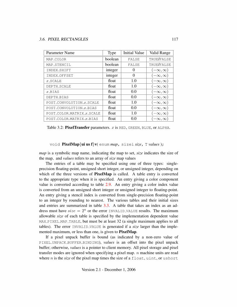
3.6. PIXEL RECTANGLES 117
Parameter Name Type Initial Value Valid RangeMAP COLOR boolean FALSE TRUE/FALSEMAP STENCIL boolean FALSE TRUE/FALSEINDEX SHIFT integer 0 (−∞,∞)INDEX OFFSET integer 0 (−∞,∞)x SCALE float 1.0 (−∞,∞)DEPTH SCALE float 1.0 (−∞,∞)x BIAS float 0.0 (−∞,∞)DEPTH BIAS float 0.0 (−∞,∞)POST CONVOLUTION x SCALE float 1.0 (−∞,∞)POST CONVOLUTION x BIAS float 0.0 (−∞,∞)POST COLOR MATRIX x SCALE float 1.0 (−∞,∞)POST COLOR MATRIX x BIAS float 0.0 (−∞,∞)
Table 3.2: PixelTransfer parameters. x is RED, GREEN, BLUE, or ALPHA.
void PixelMap{ui us f}v( enum map, sizei size, T values );
map is a symbolic map name, indicating the map to set, size indicates the size ofthe map, and values refers to an array of size map values
The entries of a table may be specified using one of three types: single-precision floating-point, unsigned short integer, or unsigned integer, depending onwhich of the three versions of PixelMap is called. A table entry is convertedto the appropriate type when it is specified. An entry giving a color componentvalue is converted according to table 2.9. An entry giving a color index valueis converted from an unsigned short integer or unsigned integer to floating-point.An entry giving a stencil index is converted from single-precision floating-pointto an integer by rounding to nearest. The various tables and their initial sizesand entries are summarized in table 3.3. A table that takes an index as an ad-dress must have size = 2n or the error INVALID VALUE results. The maximumallowable size of each table is specified by the implementation dependent valueMAX PIXEL MAP TABLE, but must be at least 32 (a single maximum applies to alltables). The error INVALID VALUE is generated if a size larger than the imple-mented maximum, or less than one, is given to PixelMap.
If a pixel unpack buffer is bound (as indicated by a non-zero value ofPIXEL UNPACK BUFFER BINDING), values is an offset into the pixel unpackbuffer; otherwise, values is a pointer to client memory. All pixel storage and pixeltransfer modes are ignored when specifying a pixel map. n machine units are readwhere n is the size of the pixel map times the size of a float, uint, or ushort
Version 2.1 - December 1, 2006
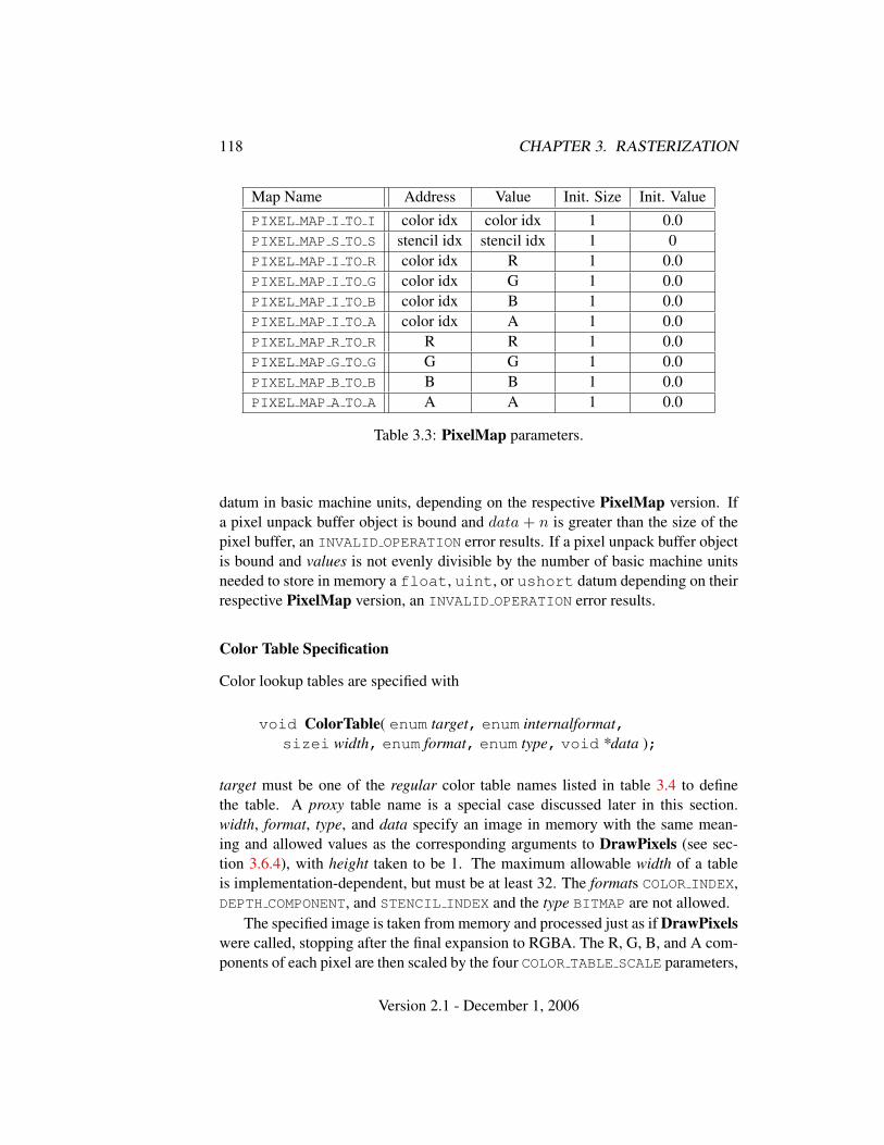
118 CHAPTER 3. RASTERIZATION
Map Name Address Value Init. Size Init. ValuePIXEL MAP I TO I color idx color idx 1 0.0PIXEL MAP S TO S stencil idx stencil idx 1 0PIXEL MAP I TO R color idx R 1 0.0PIXEL MAP I TO G color idx G 1 0.0PIXEL MAP I TO B color idx B 1 0.0PIXEL MAP I TO A color idx A 1 0.0PIXEL MAP R TO R R R 1 0.0PIXEL MAP G TO G G G 1 0.0PIXEL MAP B TO B B B 1 0.0PIXEL MAP A TO A A A 1 0.0
Table 3.3: PixelMap parameters.
datum in basic machine units, depending on the respective PixelMap version. Ifa pixel unpack buffer object is bound and data + n is greater than the size of thepixel buffer, an INVALID OPERATION error results. If a pixel unpack buffer objectis bound and values is not evenly divisible by the number of basic machine unitsneeded to store in memory a float, uint, or ushort datum depending on theirrespective PixelMap version, an INVALID OPERATION error results.
Color Table Specification
Color lookup tables are specified with
void ColorTable( enum target, enum internalformat,sizei width, enum format, enum type, void *data );
target must be one of the regular color table names listed in table 3.4 to definethe table. A proxy table name is a special case discussed later in this section.width, format, type, and data specify an image in memory with the same mean-ing and allowed values as the corresponding arguments to DrawPixels (see sec-tion 3.6.4), with height taken to be 1. The maximum allowable width of a tableis implementation-dependent, but must be at least 32. The formats COLOR INDEX,DEPTH COMPONENT, and STENCIL INDEX and the type BITMAP are not allowed.
The specified image is taken from memory and processed just as if DrawPixelswere called, stopping after the final expansion to RGBA. The R, G, B, and A com-ponents of each pixel are then scaled by the four COLOR TABLE SCALE parameters,
Version 2.1 - December 1, 2006
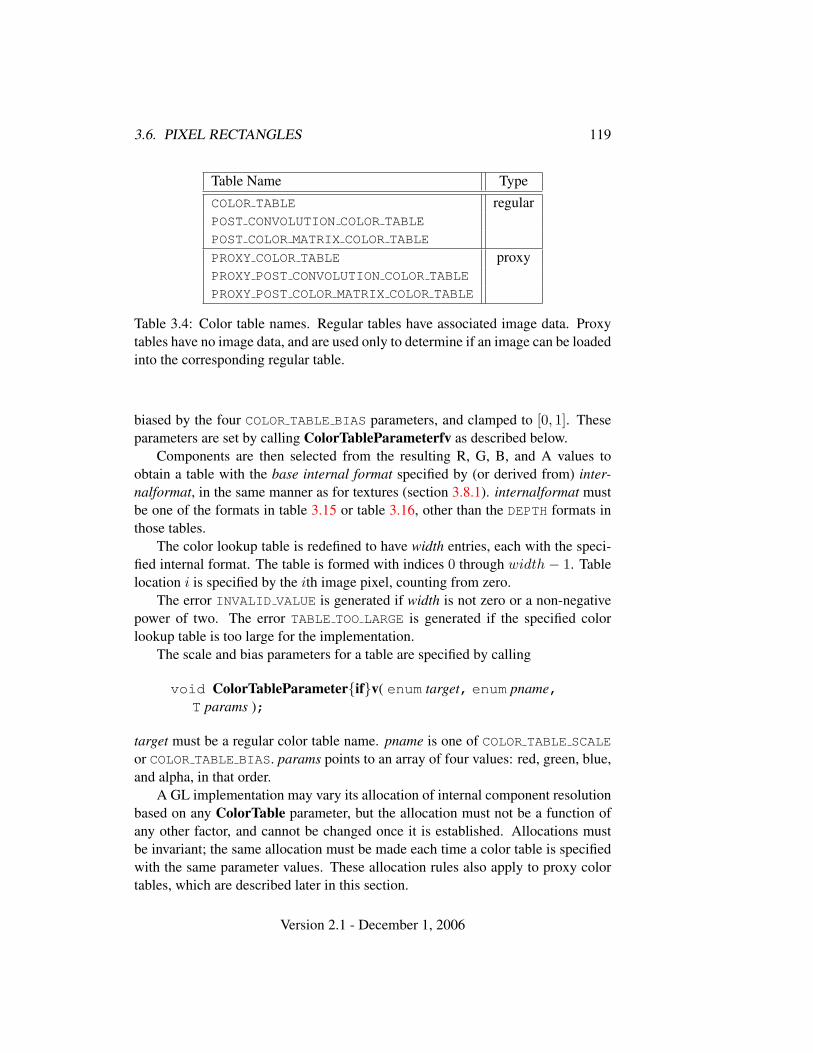
3.6. PIXEL RECTANGLES 119
Table Name TypeCOLOR TABLE regularPOST CONVOLUTION COLOR TABLE
POST COLOR MATRIX COLOR TABLE
PROXY COLOR TABLE proxyPROXY POST CONVOLUTION COLOR TABLE
PROXY POST COLOR MATRIX COLOR TABLE
Table 3.4: Color table names. Regular tables have associated image data. Proxytables have no image data, and are used only to determine if an image can be loadedinto the corresponding regular table.
biased by the four COLOR TABLE BIAS parameters, and clamped to [0, 1]. Theseparameters are set by calling ColorTableParameterfv as described below.
Components are then selected from the resulting R, G, B, and A values toobtain a table with the base internal format specified by (or derived from) inter-nalformat, in the same manner as for textures (section 3.8.1). internalformat mustbe one of the formats in table 3.15 or table 3.16, other than the DEPTH formats inthose tables.
The color lookup table is redefined to have width entries, each with the speci-fied internal format. The table is formed with indices 0 through width − 1. Tablelocation i is specified by the ith image pixel, counting from zero.
The error INVALID VALUE is generated if width is not zero or a non-negativepower of two. The error TABLE TOO LARGE is generated if the specified colorlookup table is too large for the implementation.
The scale and bias parameters for a table are specified by calling
void ColorTableParameter{if}v( enum target, enum pname,T params );
target must be a regular color table name. pname is one of COLOR TABLE SCALE
or COLOR TABLE BIAS. params points to an array of four values: red, green, blue,and alpha, in that order.
A GL implementation may vary its allocation of internal component resolutionbased on any ColorTable parameter, but the allocation must not be a function ofany other factor, and cannot be changed once it is established. Allocations mustbe invariant; the same allocation must be made each time a color table is specifiedwith the same parameter values. These allocation rules also apply to proxy colortables, which are described later in this section.
Version 2.1 - December 1, 2006
120 CHAPTER 3. RASTERIZATION
Alternate Color Table Specification Commands
Color tables may also be specified using image data taken directly from the frame-buffer, and portions of existing tables may be respecified.
The command
void CopyColorTable( enum target, enum internalformat,int x, int y, sizei width );
defines a color table in exactly the manner of ColorTable, except that table dataare taken from the framebuffer, rather than from client memory. target must be aregular color table name. x, y, and width correspond precisely to the correspondingarguments of CopyPixels (refer to section 4.3.3); they specify the image’s widthand the lower left (x, y) coordinates of the framebuffer region to be copied. Theimage is taken from the framebuffer exactly as if these arguments were passed toCopyPixels with argument type set to COLOR and height set to 1, stopping after thefinal expansion to RGBA.
Subsequent processing is identical to that described for ColorTable, beginningwith scaling by COLOR TABLE SCALE. Parameters target, internalformat and widthare specified using the same values, with the same meanings, as the equivalentarguments of ColorTable. format is taken to be RGBA.
Two additional commands,
void ColorSubTable( enum target, sizei start, sizei count,enum format, enum type, void *data );
void CopyColorSubTable( enum target, sizei start, int x,int y, sizei count );
respecify only a portion of an existing color table. No change is made to the inter-nalformat or width parameters of the specified color table, nor is any change madeto table entries outside the specified portion. target must be a regular color tablename.
ColorSubTable arguments format, type, and data match the corresponding ar-guments to ColorTable, meaning that they are specified using the same values,and have the same meanings. Likewise, CopyColorSubTable arguments x, y, andcount match the x, y, and width arguments of CopyColorTable. Both of the Color-SubTable commands interpret and process pixel groups in exactly the manner oftheir ColorTable counterparts, except that the assignment of R, G, B, and A pixelgroup values to the color table components is controlled by the internalformat ofthe table, not by an argument to the command.
Version 2.1 - December 1, 2006
3.6. PIXEL RECTANGLES 121
Arguments start and count of ColorSubTable and CopyColorSubTable spec-ify a subregion of the color table starting at index start and ending at indexstart + count − 1. Counting from zero, the nth pixel group is assigned to thetable entry with index count + n. The error INVALID VALUE is generated ifstart + count > width.
Color Table State and Proxy State
The state necessary for color tables can be divided into two categories. For eachof the three tables, there is an array of values. Each array has associated with ita width, an integer describing the internal format of the table, six integer valuesdescribing the resolutions of each of the red, green, blue, alpha, luminance, andintensity components of the table, and two groups of four floating-point numbers tostore the table scale and bias. Each initial array is null (zero width, internal formatRGBA, with zero-sized components). The initial value of the scale parameters is(1,1,1,1) and the initial value of the bias parameters is (0,0,0,0).
In addition to the color lookup tables, partially instantiated proxy color lookuptables are maintained. Each proxy table includes width and internal format statevalues, as well as state for the red, green, blue, alpha, luminance, and intensitycomponent resolutions. Proxy tables do not include image data, nor do they in-clude scale and bias parameters. When ColorTable is executed with target speci-fied as one of the proxy color table names listed in table 3.4, the proxy state valuesof the table are recomputed and updated. If the table is too large, no error is gener-ated, but the proxy format, width and component resolutions are set to zero. If thecolor table would be accommodated by ColorTable called with target set to thecorresponding regular table name (COLOR TABLE is the regular name correspond-ing to PROXY COLOR TABLE, for example), the proxy state values are set exactlyas though the regular table were being specified. Calling ColorTable with a proxytarget has no effect on the image or state of any actual color table.
There is no image associated with any of the proxy targets. They cannot beused as color tables, and they must never be queried using GetColorTable. Theerror INVALID ENUM is generated if this is attempted.
Convolution Filter Specification
A two-dimensional convolution filter image is specified by calling
void ConvolutionFilter2D( enum target, enum internalformat,sizei width, sizei height, enum format, enum type,void *data );
Version 2.1 - December 1, 2006
122 CHAPTER 3. RASTERIZATION
target must be CONVOLUTION 2D. width, height, format, type, and data specify animage in memory with the same meaning and allowed values as the correspondingparameters to DrawPixels. The formats COLOR INDEX, DEPTH COMPONENT, andSTENCIL INDEX and the type BITMAP are not allowed.
The specified image is extracted from memory and processed just as ifDrawPixels were called, stopping after the final expansion to RGBA. TheR, G, B, and A components of each pixel are then scaled by the four two-dimensional CONVOLUTION FILTER SCALE parameters and biased by the fourtwo-dimensional CONVOLUTION FILTER BIAS parameters. These parameters areset by calling ConvolutionParameterfv as described below. No clamping takesplace at any time during this process.
Components are then selected from the resulting R, G, B, and A values toobtain a table with the base internal format specified by (or derived from) inter-nalformat, in the same manner as for textures (section 3.8.1). internalformat mustbe one of the formats in table 3.15 or table 3.16, other than the DEPTH formats inthose tables.
The red, green, blue, alpha, luminance, and/or intensity components of thepixels are stored in floating point, rather than integer format. They form a two-dimensional image indexed with coordinates i, j such that i increases from left toright, starting at zero, and j increases from bottom to top, also starting at zero.Image location i, j is specified by the N th pixel, counting from zero, where
N = i + j ∗ width
The error INVALID VALUE is generated if width or height is greaterthan the maximum supported value. These values are queried with Get-ConvolutionParameteriv, setting target to CONVOLUTION 2D and pname toMAX CONVOLUTION WIDTH or MAX CONVOLUTION HEIGHT, respectively.
The scale and bias parameters for a two-dimensional filter are specified bycalling
void ConvolutionParameter{if}v( enum target, enum pname,T params );
with target CONVOLUTION 2D. pname is one of CONVOLUTION FILTER SCALE
or CONVOLUTION FILTER BIAS. params points to an array of four values: red,green, blue, and alpha, in that order.
A one-dimensional convolution filter is defined using
void ConvolutionFilter1D( enum target, enum internalformat,sizei width, enum format, enum type, void *data );
Version 2.1 - December 1, 2006
3.6. PIXEL RECTANGLES 123
target must be CONVOLUTION 1D. internalformat, width, format, and type haveidentical semantics and accept the same values as do their two-dimensional coun-terparts. data must point to a one-dimensional image, however.
The image is extracted from memory and processed as if ConvolutionFilter2Dwere called with a height of 1, except that it is scaled and biased by the one-dimensional CONVOLUTION FILTER SCALE and CONVOLUTION FILTER BIAS
parameters. These parameters are specified exactly as the two-dimensionalparameters, except that ConvolutionParameterfv is called with targetCONVOLUTION 1D.
The image is formed with coordinates i such that i increases from left to right,starting at zero. Image location i is specified by the ith pixel, counting from zero.
The error INVALID VALUE is generated if width is greater than the maximumsupported value. This value is queried using GetConvolutionParameteriv, settingtarget to CONVOLUTION 1D and pname to MAX CONVOLUTION WIDTH.
Special facilities are provided for the definition of two-dimensional sepa-rable filters – filters whose image can be represented as the product of twoone-dimensional images, rather than as full two-dimensional images. A two-dimensional separable convolution filter is specified with
void SeparableFilter2D( enum target, enum internalformat,sizei width, sizei height, enum format, enum type,void *row, void *column );
target must be SEPARABLE 2D. internalformat specifies the formats of the tableentries of the two one-dimensional images that will be retained. row points to awidth pixel wide image of the specified format and type. column points to a heightpixel high image, also of the specified format and type.
The two images are extracted from memory and processed as if Convolu-tionFilter1D were called separately for each, except that each image is scaledand biased by the two-dimensional separable CONVOLUTION FILTER SCALE andCONVOLUTION FILTER BIAS parameters. These parameters are specified exactlyas the one-dimensional and two-dimensional parameters, except that Convolution-Parameteriv is called with target SEPARABLE 2D.
Alternate Convolution Filter Specification Commands
One and two-dimensional filters may also be specified using image data taken di-rectly from the framebuffer.
The command
Version 2.1 - December 1, 2006
124 CHAPTER 3. RASTERIZATION
void CopyConvolutionFilter2D( enum target,enum internalformat, int x, int y, sizei width,sizei height );
defines a two-dimensional filter in exactly the manner of ConvolutionFilter2D,except that image data are taken from the framebuffer, rather than from client mem-ory. target must be CONVOLUTION 2D. x, y, width, and height correspond preciselyto the corresponding arguments of CopyPixels (refer to section 4.3.3); they specifythe image’s width and height, and the lower left (x, y) coordinates of the frame-buffer region to be copied. The image is taken from the framebuffer exactly asif these arguments were passed to CopyPixels with argument type set to COLOR,stopping after the final expansion to RGBA.
Subsequent processing is identical to that described for ConvolutionFilter2D,beginning with scaling by CONVOLUTION FILTER SCALE. Parameters target, in-ternalformat, width, and height are specified using the same values, with the samemeanings, as the equivalent arguments of ConvolutionFilter2D. format is taken tobe RGBA.
The command
void CopyConvolutionFilter1D( enum target,enum internalformat, int x, int y, sizei width );
defines a one-dimensional filter in exactly the manner of ConvolutionFilter1D,except that image data are taken from the framebuffer, rather than from client mem-ory. target must be CONVOLUTION 1D. x, y, and width correspond precisely to thecorresponding arguments of CopyPixels (refer to section 4.3.3); they specify theimage’s width and the lower left (x, y) coordinates of the framebuffer region tobe copied. The image is taken from the framebuffer exactly as if these argumentswere passed to CopyPixels with argument type set to COLOR and height set to 1,stopping after the final expansion to RGBA.
Subsequent processing is identical to that described for ConvolutionFilter1D,beginning with scaling by CONVOLUTION FILTER SCALE. Parameters target, in-ternalformat, and width are specified using the same values, with the same mean-ings, as the equivalent arguments of ConvolutionFilter2D. format is taken to beRGBA.
Convolution Filter State
The required state for convolution filters includes a one-dimensional image array,two one-dimensional image arrays for the separable filter, and a two-dimensionalimage array. Each filter has associated with it a width and height (two-dimensional
Version 2.1 - December 1, 2006
3.6. PIXEL RECTANGLES 125
and separable only), an integer describing the internal format of the filter, and twogroups of four floating-point numbers to store the filter scale and bias.
Each initial convolution filter is null (zero width and height, internal formatRGBA, with zero-sized components). The initial value of all scale parameters is(1,1,1,1) and the initial value of all bias parameters is (0,0,0,0).
Color Matrix Specification
Setting the matrix mode to COLOR causes the matrix operations described in sec-tion 2.11.2 to apply to the top matrix on the color matrix stack. All matrix opera-tions have the same effect on the color matrix as they do on the other matrices.
Histogram Table Specification
The histogram table is specified with
void Histogram( enum target, sizei width,enum internalformat, boolean sink );
target must be HISTOGRAM if a histogram table is to be specified. target valuePROXY HISTOGRAM is a special case discussed later in this section. width speci-fies the number of entries in the histogram table, and internalformat specifies theformat of each table entry. The maximum allowable width of the histogram tableis implementation-dependent, but must be at least 32. sink specifies whether pixelgroups will be consumed by the histogram operation (TRUE) or passed on to theminmax operation (FALSE).
If no error results from the execution of Histogram, the specified histogramtable is redefined to have width entries, each with the specified internal format.The entries are indexed 0 through width− 1. Each component in each entry is setto zero. The values in the previous histogram table, if any, are lost.
The error INVALID VALUE is generated if width is not zero or a non-negativepower of two. The error TABLE TOO LARGE is generated if the specified histogramtable is too large for the implementation. The error INVALID ENUM is generated ifinternalformat is not one of the formats in table 3.15 or table 3.16, or is 1, 2, 3, 4,or any of the DEPTH or INTENSITY formats in those tables.
A GL implementation may vary its allocation of internal component resolutionbased on any Histogram parameter, but the allocation must not be a function of anyother factor, and cannot be changed once it is established. In particular, allocationsmust be invariant; the same allocation must be made each time a histogram isspecified with the same parameter values. These allocation rules also apply to theproxy histogram, which is described later in this section.
Version 2.1 - December 1, 2006
126 CHAPTER 3. RASTERIZATION
Histogram State and Proxy State
The state necessary for histogram operation is an array of values, with which isassociated a width, an integer describing the internal format of the histogram, fiveinteger values describing the resolutions of each of the red, green, blue, alpha,and luminance components of the table, and a flag indicating whether or not pixelgroups are consumed by the operation. The initial array is null (zero width, internalformat RGBA, with zero-sized components). The initial value of the flag is false.
In addition to the histogram table, a partially instantiated proxy histogram tableis maintained. It includes width, internal format, and red, green, blue, alpha, andluminance component resolutions. The proxy table does not include image data orthe flag. When Histogram is executed with target set to PROXY HISTOGRAM, theproxy state values are recomputed and updated. If the histogram array is too large,no error is generated, but the proxy format, width, and component resolutions areset to zero. If the histogram table would be accomodated by Histogram calledwith target set to HISTOGRAM, the proxy state values are set exactly as thoughthe actual histogram table were being specified. Calling Histogram with targetPROXY HISTOGRAM has no effect on the actual histogram table.
There is no image associated with PROXY HISTOGRAM. It cannot be used asa histogram, and its image must never queried using GetHistogram. The errorINVALID ENUM results if this is attempted.
Minmax Table Specification
The minmax table is specified with
void Minmax( enum target, enum internalformat,boolean sink );
target must be MINMAX. internalformat specifies the format of the table entries.sink specifies whether pixel groups will be consumed by the minmax operation(TRUE) or passed on to final conversion (FALSE).
The error INVALID ENUM is generated if internalformat is not one of the for-mats in table 3.15 or table 3.16, or is 1, 2, 3, 4, or any of the DEPTH or INTENSITYformats in those tables. The resulting table always has 2 entries, each with valuescorresponding only to the components of the internal format.
The state necessary for minmax operation is a table containing two elements(the first element stores the minimum values, the second stores the maximum val-ues), an integer describing the internal format of the table, and a flag indicatingwhether or not pixel groups are consumed by the operation. The initial state isa minimum table entry set to the maximum representable value and a maximum
Version 2.1 - December 1, 2006
3.6. PIXEL RECTANGLES 127
table entry set to the minimum representable value. Internal format is set to RGBA
and the initial value of the flag is false.
3.6.4 Rasterization of Pixel Rectangles
The process of drawing pixels encoded in buffer object or client memory is dia-grammed in figure 3.7. We describe the stages of this process in the order in whichthey occur.
Pixels are drawn using
void DrawPixels( sizei width, sizei height, enum format,enum type, void *data );
format is a symbolic constant indicating what the values in memory represent.width and height are the width and height, respectively, of the pixel rectangle tobe drawn. data refers to the data to be drawn. The correspondence betweenthe twenty type token values and the GL data types they indicate is given in ta-ble 3.5. If the GL is in color index mode and format is not one of COLOR INDEX,STENCIL INDEX, or DEPTH COMPONENT, then the error INVALID OPERATION oc-curs. If type is BITMAP and format is not COLOR INDEX or STENCIL INDEX thenthe error INVALID ENUM occurs. Some additional constraints on the combinationsof format and type values that are accepted are discussed below.
Unpacking
Data are taken from the currently bound pixel unpack buffer or client memory as asequence of signed or unsigned bytes (GL data types byte and ubyte), signed orunsigned short integers (GL data types short and ushort), signed or unsignedintegers (GL data types int and uint), or floating point values (GL data typefloat). These elements are grouped into sets of one, two, three, or four values,depending on the format, to form a group. Table 3.6 summarizes the format ofgroups obtained from memory; it also indicates those formats that yield indicesand those that yield components.
If a pixel unpack buffer is bound (as indicated by a non-zero value ofPIXEL UNPACK BUFFER BINDING), data is an offset into the pixel unpack bufferand the pixels are unpacked from the buffer relative to this offset; otherwise, data isa pointer to client memory and the pixels are unpacked from client memory relativeto the pointer. If a pixel unpack buffer object is bound and unpacking the pixel dataaccording to the process described below would access memory beyond the size ofthe pixel unpack buffer’s memory size, an INVALID OPERATION error results. If apixel unpack buffer object is bound and data is not evenly divisible by the number
Version 2.1 - December 1, 2006
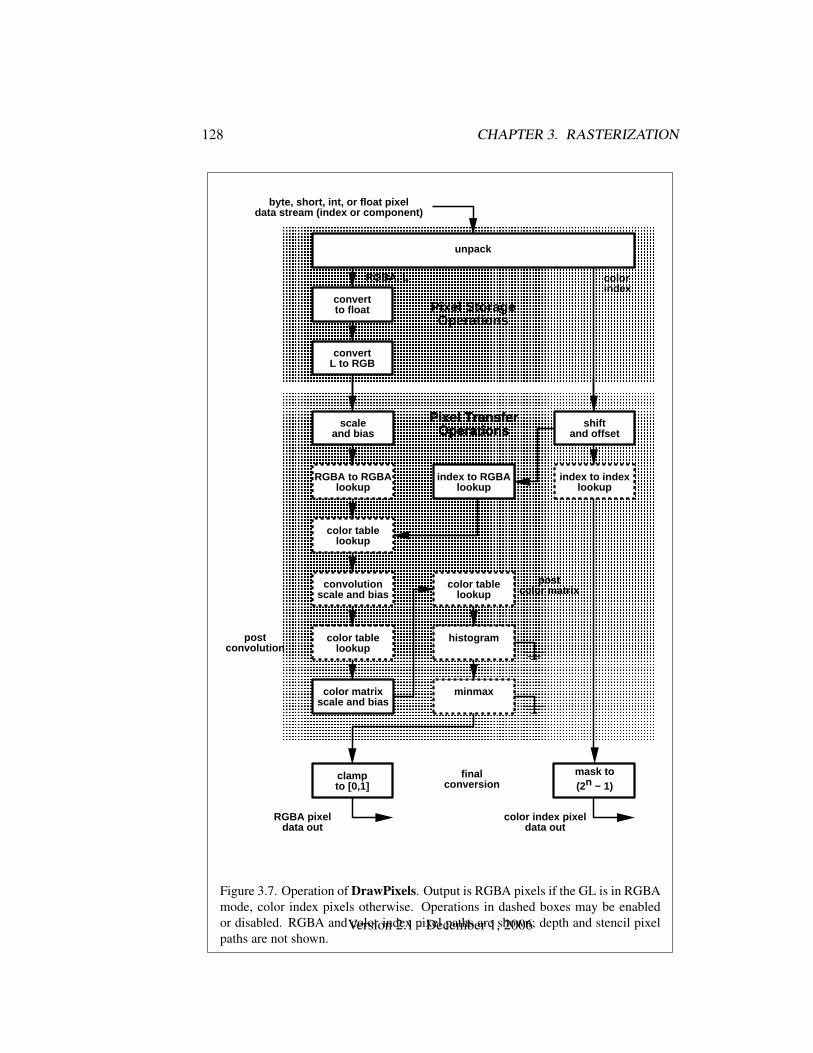
128 CHAPTER 3. RASTERIZATION
� � � � � � � � � � � � � � � � � � � � � � � � � � � � � � �� � � � � � � � � � � � � � � � � � � � � � � � � � � � � � �� � � � � � � � � � � � � � � � � � � � � � � � � � � � � � �� � � � � � � � � � � � � � � � � � � � � � � � � � � � � � �� � � � � � � � � � � � � � � � � � � � � � � � � � � � � � �� � � � � � � � � � � � � � � � � � � � � � � � � � � � � � �� � � � � � � � � � � � � � � � � � � � � � � � � � � � � � �� � � � � � � � � � � � � � � � � � � � � � � � � � � � � � �� � � � � � � � � � � � � � � � � � � � � � � � � � � � � � �� � � � � � � � � � � � � � � � � � � � � � � � � � � � � � �� � � � � � � � � � � � � � � � � � � � � � � � � � � � � � �� � � � � � � � � � � � � � � � � � � � � � � � � � � � � � �� � � � � � � � � � � � � � � � � � � � � � � � � � � � � � �
unpack
convertto float
convertL to RGB
RGBA, L
Pixel StorageOperations
byte, short, int, o r float pixeldata stream (index or component)
colorindex
postconvolution
� � � � � � � � � � � � � � � � � � � � � � � � � � � � � � � �� � � � � � � � � � � � � � � � � � � � � � � � � � � � � � � �� � � � � � � � � � � � � � � � � � � � � � � � � � � � � � � �� � � � � � � � � � � � � � � � � � � � � � � � � � � � � � � �� � � � � � � � � � � � � � � � � � � � � � � � � � � � � � � �� � � � � � � � � � � � � � � � � � � � � � � � � � � � � � � �� � � � � � � � � � � � � � � � � � � � � � � � � � � � � � � �� � � � � � � � � � � � � � � � � � � � � � � � � � � � � � � �� � � � � � � � � � � � � � � � � � � � � � � � � � � � � � � �� � � � � � � � � � � � � � � � � � � � � � � � � � � � � � � �� � � � � � � � � � � � � � � � � � � � � � � � � � � � � � � �� � � � � � � � � � � � � � � � � � � � � � � � � � � � � � � �� � � � � � � � � � � � � � � � � � � � � � � � � � � � � � � �� � � � � � � � � � � � � � � � � � � � � � � � � � � � � � � �� � � � � � � � � � � � � � � � � � � � � � � � � � � � � � � �� � � � � � � � � � � � � � � � � � � � � � � � � � � � � � � �� � � � � � � � � � � � � � � � � � � � � � � � � � � � � � � �� � � � � � � � � � � � � � � � � � � � � � � � � � � � � � � �� � � � � � � � � � � � � � � � � � � � � � � � � � � � � � � �� � � � � � � � � � � � � � � � � � � � � � � � � � � � � � � �� � � � � � � � � � � � � � � � � � � � � � � � � � � � � � � �� � � � � � � � � � � � � � � � � � � � � � � � � � � � � � � �� � � � � � � � � � � � � � � � � � � � � � � � � � � � � � � �� � � � � � � � � � � � � � � � � � � � � � � � � � � � � � � �� � � � � � � � � � � � � � � � � � � � � � � � � � � � � � � �� � � � � � � � � � � � � � � � � � � � � � � � � � � � � � � �� � � � � � � � � � � � � � � � � � � � � � � � � � � � � � � �� � � � � � � � � � � � � � � � � � � � � � � � � � � � � � � �� � � � � � � � � � � � � � � � � � � � � � � � � � � � � � � �
scaleand bias
Pixel TransferOperations
color table lookup
convolution scale a nd bias
histogram
minmax
color table lookup
RGBA to RGBA lookup
shiftand offset
index to index look up
index to RGBA looku p
color table lookup
color matrixscale and bias
postcolor matrix
color index pixeldata out
RGBA pixeldata out
clampto [0,1]
mask to(2n − 1)
finalconversion
Figure 3.7. Operation of DrawPixels. Output is RGBA pixels if the GL is in RGBAmode, color index pixels otherwise. Operations in dashed boxes may be enabledor disabled. RGBA and color index pixel paths are shown; depth and stencil pixelpaths are not shown.
Version 2.1 - December 1, 2006
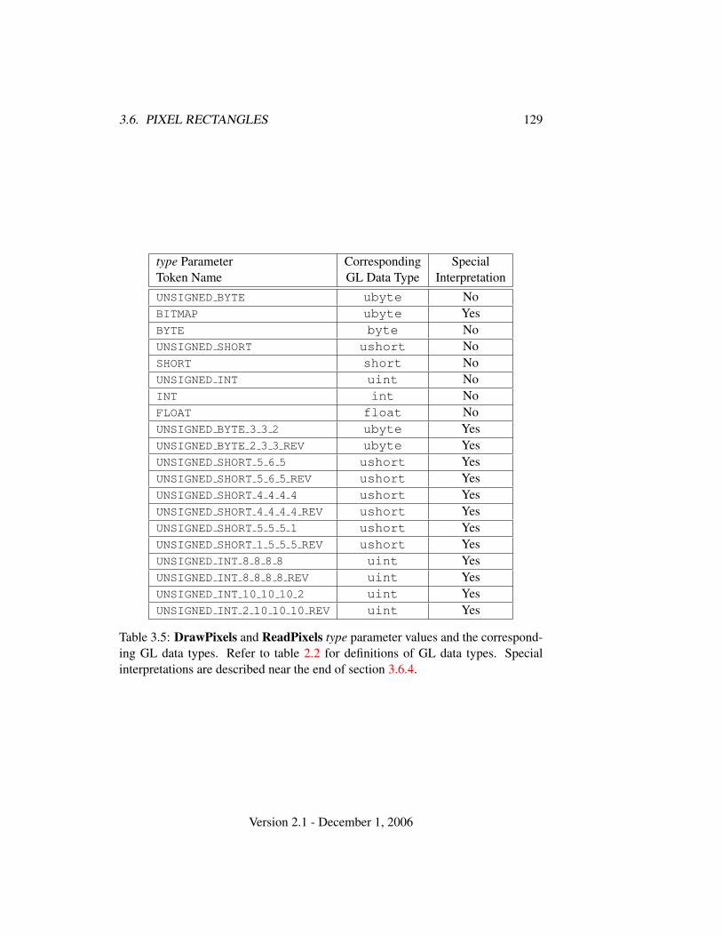
3.6. PIXEL RECTANGLES 129
type Parameter Corresponding SpecialToken Name GL Data Type InterpretationUNSIGNED BYTE ubyte NoBITMAP ubyte YesBYTE byte NoUNSIGNED SHORT ushort NoSHORT short NoUNSIGNED INT uint NoINT int NoFLOAT float NoUNSIGNED BYTE 3 3 2 ubyte YesUNSIGNED BYTE 2 3 3 REV ubyte YesUNSIGNED SHORT 5 6 5 ushort YesUNSIGNED SHORT 5 6 5 REV ushort YesUNSIGNED SHORT 4 4 4 4 ushort YesUNSIGNED SHORT 4 4 4 4 REV ushort YesUNSIGNED SHORT 5 5 5 1 ushort YesUNSIGNED SHORT 1 5 5 5 REV ushort YesUNSIGNED INT 8 8 8 8 uint YesUNSIGNED INT 8 8 8 8 REV uint YesUNSIGNED INT 10 10 10 2 uint YesUNSIGNED INT 2 10 10 10 REV uint Yes
Table 3.5: DrawPixels and ReadPixels type parameter values and the correspond-ing GL data types. Refer to table 2.2 for definitions of GL data types. Specialinterpretations are described near the end of section 3.6.4.
Version 2.1 - December 1, 2006
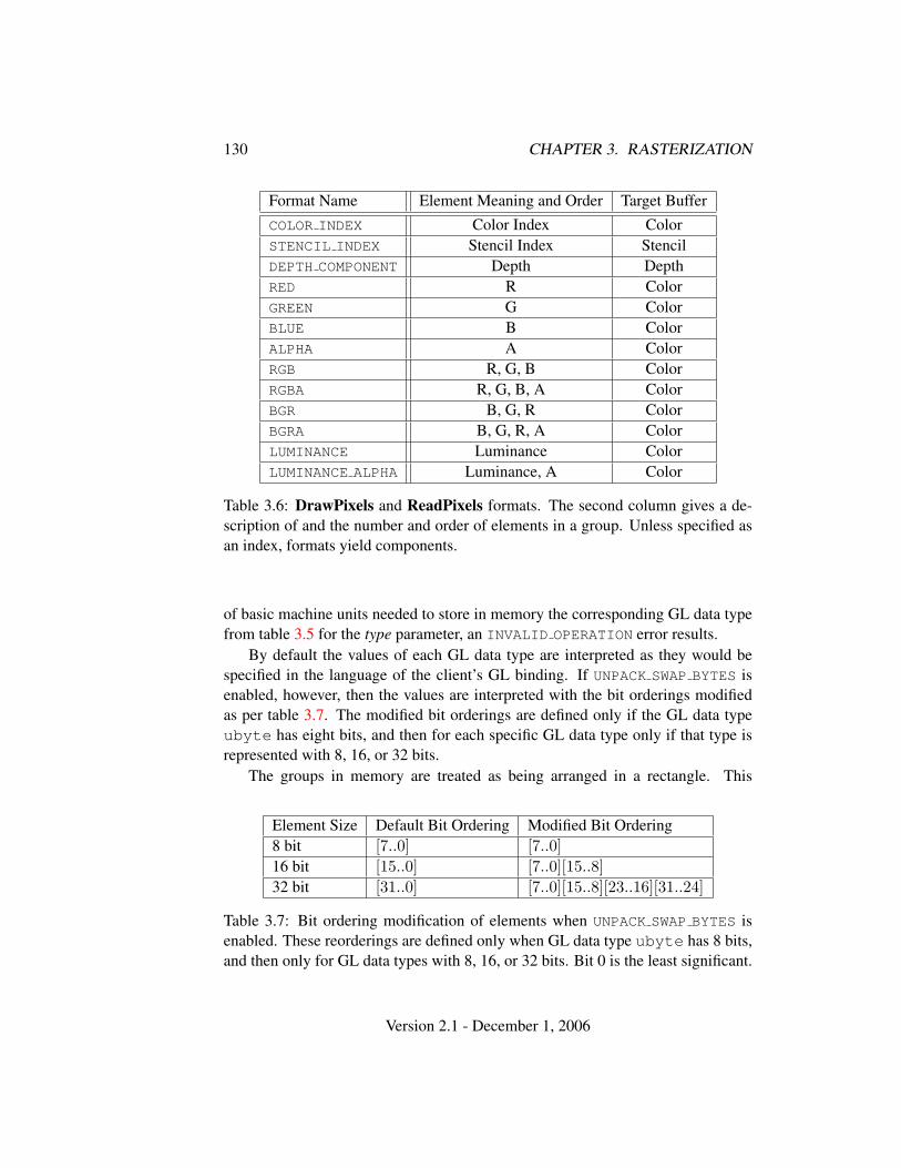
130 CHAPTER 3. RASTERIZATION
Format Name Element Meaning and Order Target BufferCOLOR INDEX Color Index ColorSTENCIL INDEX Stencil Index StencilDEPTH COMPONENT Depth DepthRED R ColorGREEN G ColorBLUE B ColorALPHA A ColorRGB R, G, B ColorRGBA R, G, B, A ColorBGR B, G, R ColorBGRA B, G, R, A ColorLUMINANCE Luminance ColorLUMINANCE ALPHA Luminance, A Color
Table 3.6: DrawPixels and ReadPixels formats. The second column gives a de-scription of and the number and order of elements in a group. Unless specified asan index, formats yield components.
of basic machine units needed to store in memory the corresponding GL data typefrom table 3.5 for the type parameter, an INVALID OPERATION error results.
By default the values of each GL data type are interpreted as they would bespecified in the language of the client’s GL binding. If UNPACK SWAP BYTES isenabled, however, then the values are interpreted with the bit orderings modifiedas per table 3.7. The modified bit orderings are defined only if the GL data typeubyte has eight bits, and then for each specific GL data type only if that type isrepresented with 8, 16, or 32 bits.
The groups in memory are treated as being arranged in a rectangle. This
Element Size Default Bit Ordering Modified Bit Ordering8 bit [7..0] [7..0]16 bit [15..0] [7..0][15..8]32 bit [31..0] [7..0][15..8][23..16][31..24]
Table 3.7: Bit ordering modification of elements when UNPACK SWAP BYTES isenabled. These reorderings are defined only when GL data type ubyte has 8 bits,and then only for GL data types with 8, 16, or 32 bits. Bit 0 is the least significant.
Version 2.1 - December 1, 2006
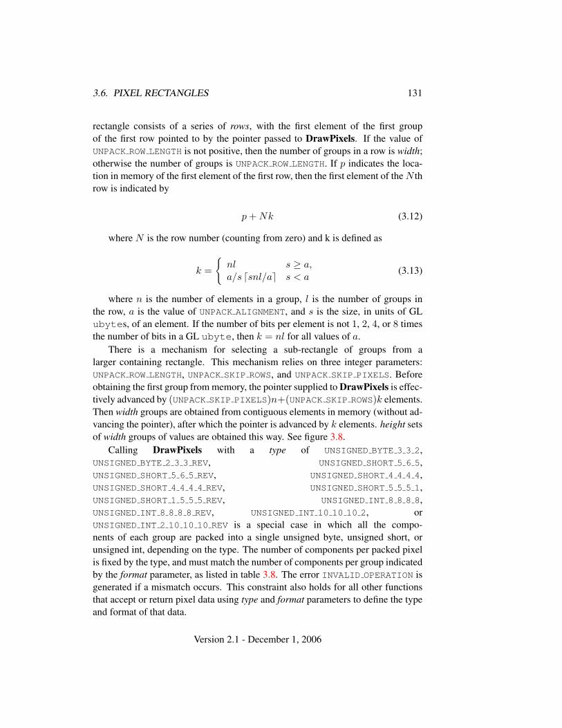
3.6. PIXEL RECTANGLES 131
rectangle consists of a series of rows, with the first element of the first groupof the first row pointed to by the pointer passed to DrawPixels. If the value ofUNPACK ROW LENGTH is not positive, then the number of groups in a row is width;otherwise the number of groups is UNPACK ROW LENGTH. If p indicates the loca-tion in memory of the first element of the first row, then the first element of the N throw is indicated by
p + Nk (3.12)
where N is the row number (counting from zero) and k is defined as
k =
{nl s ≥ a,a/s dsnl/ae s < a
(3.13)
where n is the number of elements in a group, l is the number of groups inthe row, a is the value of UNPACK ALIGNMENT, and s is the size, in units of GLubytes, of an element. If the number of bits per element is not 1, 2, 4, or 8 timesthe number of bits in a GL ubyte, then k = nl for all values of a.
There is a mechanism for selecting a sub-rectangle of groups from alarger containing rectangle. This mechanism relies on three integer parameters:UNPACK ROW LENGTH, UNPACK SKIP ROWS, and UNPACK SKIP PIXELS. Beforeobtaining the first group from memory, the pointer supplied to DrawPixels is effec-tively advanced by (UNPACK SKIP PIXELS)n+(UNPACK SKIP ROWS)k elements.Then width groups are obtained from contiguous elements in memory (without ad-vancing the pointer), after which the pointer is advanced by k elements. height setsof width groups of values are obtained this way. See figure 3.8.
Calling DrawPixels with a type of UNSIGNED BYTE 3 3 2,UNSIGNED BYTE 2 3 3 REV, UNSIGNED SHORT 5 6 5,UNSIGNED SHORT 5 6 5 REV, UNSIGNED SHORT 4 4 4 4,UNSIGNED SHORT 4 4 4 4 REV, UNSIGNED SHORT 5 5 5 1,UNSIGNED SHORT 1 5 5 5 REV, UNSIGNED INT 8 8 8 8,UNSIGNED INT 8 8 8 8 REV, UNSIGNED INT 10 10 10 2, orUNSIGNED INT 2 10 10 10 REV is a special case in which all the compo-nents of each group are packed into a single unsigned byte, unsigned short, orunsigned int, depending on the type. The number of components per packed pixelis fixed by the type, and must match the number of components per group indicatedby the format parameter, as listed in table 3.8. The error INVALID OPERATION isgenerated if a mismatch occurs. This constraint also holds for all other functionsthat accept or return pixel data using type and format parameters to define the typeand format of that data.
Version 2.1 - December 1, 2006
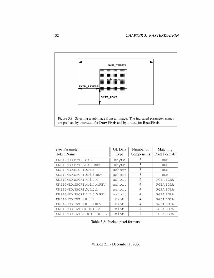
132 CHAPTER 3. RASTERIZATION
� � � � � � � � � �� � � � � � � � � �� � � � � � � � � �� � � � � � � � � �� � � � � � � � � �� � � � � � � � � �� � � � � � � � � �� � � � � � � � � �
SKIP_ROWS
SKIP_PIXELS
ROW_LENGTH
subimage
Figure 3.8. Selecting a subimage from an image. The indicated parameter namesare prefixed by UNPACK for DrawPixels and by PACK for ReadPixels.
type Parameter GL Data Number of MatchingToken Name Type Components Pixel FormatsUNSIGNED BYTE 3 3 2 ubyte 3 RGB
UNSIGNED BYTE 2 3 3 REV ubyte 3 RGB
UNSIGNED SHORT 5 6 5 ushort 3 RGB
UNSIGNED SHORT 5 6 5 REV ushort 3 RGB
UNSIGNED SHORT 4 4 4 4 ushort 4 RGBA,BGRAUNSIGNED SHORT 4 4 4 4 REV ushort 4 RGBA,BGRAUNSIGNED SHORT 5 5 5 1 ushort 4 RGBA,BGRAUNSIGNED SHORT 1 5 5 5 REV ushort 4 RGBA,BGRAUNSIGNED INT 8 8 8 8 uint 4 RGBA,BGRAUNSIGNED INT 8 8 8 8 REV uint 4 RGBA,BGRAUNSIGNED INT 10 10 10 2 uint 4 RGBA,BGRAUNSIGNED INT 2 10 10 10 REV uint 4 RGBA,BGRA
Table 3.8: Packed pixel formats.
Version 2.1 - December 1, 2006
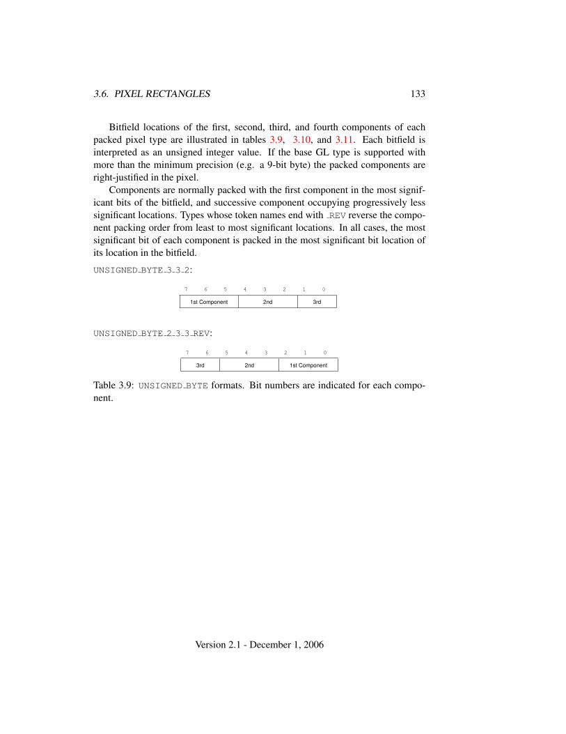
3.6. PIXEL RECTANGLES 133
Bitfield locations of the first, second, third, and fourth components of eachpacked pixel type are illustrated in tables 3.9, 3.10, and 3.11. Each bitfield isinterpreted as an unsigned integer value. If the base GL type is supported withmore than the minimum precision (e.g. a 9-bit byte) the packed components areright-justified in the pixel.
Components are normally packed with the first component in the most signif-icant bits of the bitfield, and successive component occupying progressively lesssignificant locations. Types whose token names end with REV reverse the compo-nent packing order from least to most significant locations. In all cases, the mostsignificant bit of each component is packed in the most significant bit location ofits location in the bitfield.
UNSIGNED BYTE 3 3 2:
7 6 5 4 3 2 1 0
1st Component 2nd 3rd
UNSIGNED BYTE 2 3 3 REV:
7 6 5 4 3 2 1 0
3rd 2nd 1st Component
Table 3.9: UNSIGNED BYTE formats. Bit numbers are indicated for each compo-nent.
Version 2.1 - December 1, 2006
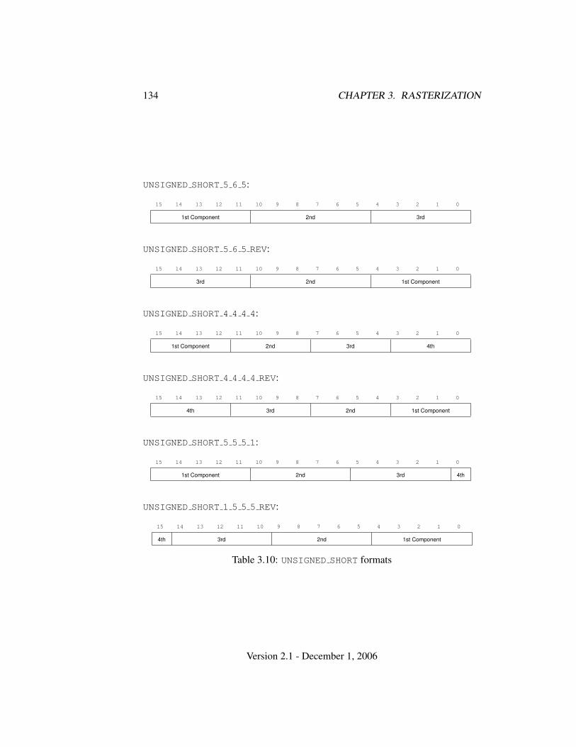
134 CHAPTER 3. RASTERIZATION
UNSIGNED SHORT 5 6 5:
15 14 13 12 11 10 9 8 7 6 5 4 3 2 1 0
1st Component 2nd 3rd
UNSIGNED SHORT 5 6 5 REV:
15 14 13 12 11 10 9 8 7 6 5 4 3 2 1 0
3rd 2nd 1st Component
UNSIGNED SHORT 4 4 4 4:
15 14 13 12 11 10 9 8 7 6 5 4 3 2 1 0
1st Component 2nd 3rd 4th
UNSIGNED SHORT 4 4 4 4 REV:
15 14 13 12 11 10 9 8 7 6 5 4 3 2 1 0
4th 3rd 2nd 1st Component
UNSIGNED SHORT 5 5 5 1:
15 14 13 12 11 10 9 8 7 6 5 4 3 2 1 0
1st Component 2nd 3rd 4th
UNSIGNED SHORT 1 5 5 5 REV:
15 14 13 12 11 10 9 8 7 6 5 4 3 2 1 0
4th 3rd 2nd 1st Component
Table 3.10: UNSIGNED SHORT formats
Version 2.1 - December 1, 2006
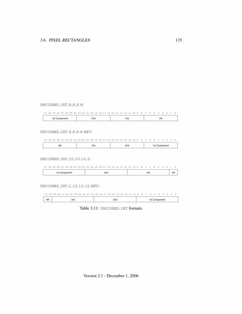
3.6. PIXEL RECTANGLES 135
UNSIGNED INT 8 8 8 8:
31 30 29 28 27 26 25 24 23 22 21 20 19 18 17 16 15 14 13 12 11 10 9 8 7 6 5 4 3 2 1 0
1st Component 2nd 3rd 4th
UNSIGNED INT 8 8 8 8 REV:
31 30 29 28 27 26 25 24 23 22 21 20 19 18 17 16 15 14 13 12 11 10 9 8 7 6 5 4 3 2 1 0
4th 3rd 2nd 1st Component
UNSIGNED INT 10 10 10 2:
31 30 29 28 27 26 25 24 23 22 21 20 19 18 17 16 15 14 13 12 11 10 9 8 7 6 5 4 3 2 1 0
1st Component 2nd 3rd 4th
UNSIGNED INT 2 10 10 10 REV:
31 30 29 28 27 26 25 24 23 22 21 20 19 18 17 16 15 14 13 12 11 10 9 8 7 6 5 4 3 2 1 0
4th 3rd 2nd 1st Component
Table 3.11: UNSIGNED INT formats
Version 2.1 - December 1, 2006
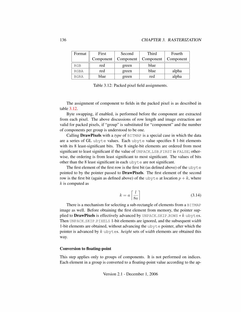
136 CHAPTER 3. RASTERIZATION
Format First Second Third FourthComponent Component Component Component
RGB red green blueRGBA red green blue alphaBGRA blue green red alpha
Table 3.12: Packed pixel field assignments.
The assignment of component to fields in the packed pixel is as described intable 3.12.
Byte swapping, if enabled, is performed before the component are extractedfrom each pixel. The above discussions of row length and image extraction arevalid for packed pixels, if “group” is substituted for “component” and the numberof components per group is understood to be one.
Calling DrawPixels with a type of BITMAP is a special case in which the dataare a series of GL ubyte values. Each ubyte value specifies 8 1-bit elementswith its 8 least-significant bits. The 8 single-bit elements are ordered from mostsignificant to least significant if the value of UNPACK LSB FIRST is FALSE; other-wise, the ordering is from least significant to most significant. The values of bitsother than the 8 least significant in each ubyte are not significant.
The first element of the first row is the first bit (as defined above) of the ubytepointed to by the pointer passed to DrawPixels. The first element of the secondrow is the first bit (again as defined above) of the ubyte at location p + k, wherek is computed as
k = a
⌈l
8a
⌉(3.14)
There is a mechanism for selecting a sub-rectangle of elements from a BITMAPimage as well. Before obtaining the first element from memory, the pointer sup-plied to DrawPixels is effectively advanced by UNPACK SKIP ROWS ∗ k ubytes.Then UNPACK SKIP PIXELS 1-bit elements are ignored, and the subsequent width1-bit elements are obtained, without advancing the ubyte pointer, after which thepointer is advanced by k ubytes. height sets of width elements are obtained thisway.
Conversion to floating-point
This step applies only to groups of components. It is not performed on indices.Each element in a group is converted to a floating-point value according to the ap-
Version 2.1 - December 1, 2006
3.6. PIXEL RECTANGLES 137
propriate formula in table 2.9 (section 2.14). For packed pixel types, each elementin the group is converted by computing c / (2N − 1), where c is the unsigned inte-ger value of the bitfield containing the element and N is the number of bits in thebitfield.
Conversion to RGB
This step is applied only if the format is LUMINANCE or LUMINANCE ALPHA. If theformat is LUMINANCE, then each group of one element is converted to a group ofR, G, and B (three) elements by copying the original single element into each ofthe three new elements. If the format is LUMINANCE ALPHA, then each group oftwo elements is converted to a group of R, G, B, and A (four) elements by copyingthe first original element into each of the first three new elements and copying thesecond original element to the A (fourth) new element.
Final Expansion to RGBA
This step is performed only for non-depth component groups. Each group is con-verted to a group of 4 elements as follows: if a group does not contain an A element,then A is added and set to 1.0. If any of R, G, or B is missing from the group, eachmissing element is added and assigned a value of 0.0.
Pixel Transfer Operations
This step is actually a sequence of steps. Because the pixel transfer operationsare performed equivalently during the drawing, copying, and reading of pixels,and during the specification of texture images (either from memory or from theframebuffer), they are described separately in section 3.6.5. After the processingdescribed in that section is completed, groups are processed as described in thefollowing sections.
Final Conversion
For a color index, final conversion consists of masking the bits of the index to theleft of the binary point by 2n − 1, where n is the number of bits in an index buffer.For RGBA components, each element is clamped to [0, 1]. The resulting values areconverted to fixed-point according to the rules given in section 2.14.9 (Final ColorProcessing).
For a depth component, an element is first clamped to [0, 1] and then convertedto fixed-point as if it were a window z value (see section 2.11.1, Controlling theViewport).
Version 2.1 - December 1, 2006
138 CHAPTER 3. RASTERIZATION
Stencil indices are masked by 2n − 1, where n is the number of bits in thestencil buffer.
Conversion to Fragments
The conversion of a group to fragments is controlled with
void PixelZoom( float zx, float zy );
Let (xrp, yrp) be the current raster position (section 2.13). (If the current rasterposition is invalid, then DrawPixels is ignored; pixel transfer operations do notupdate the histogram or minmax tables, and no fragments are generated. However,the histogram and minmax tables are updated even if the corresponding fragmentsare later rejected by the pixel ownership (section 4.1.1) or scissor (section 4.1.2)tests.) If a particular group (index or components) is the nth in a row and belongs tothe mth row, consider the region in window coordinates bounded by the rectanglewith corners
(xrp + zxn, yrp + zym) and (xrp + zx(n + 1), yrp + zy(m + 1))
(either zx or zy may be negative). A fragment representing group (n, m) is pro-duced for each framebuffer pixel inside, or on the bottom or left boundary, of thisrectangle
A fragment arising from a group consisting of color data takes on the colorindex or color components of the group and the current raster position’s associateddepth value, while a fragment arising from a depth component takes that compo-nent’s depth value and the current raster position’s associated color index or colorcomponents. In both cases, the fog coordinate is taken from the current raster posi-tion’s associated raster distance, the secondary color is taken from the current rasterposition’s associated secondary color, and texture coordinates are taken from thecurrent raster position’s associated texture coordinates. Groups arising from Draw-Pixels with a format of STENCIL INDEX are treated specially and are described insection 4.3.1.
3.6.5 Pixel Transfer Operations
The GL defines four kinds of pixel groups:
1. RGBA component: Each group comprises four color components: red, green,blue, and alpha.
2. Depth component: Each group comprises a single depth component.
Version 2.1 - December 1, 2006
3.6. PIXEL RECTANGLES 139
3. Color index: Each group comprises a single color index.
4. Stencil index: Each group comprises a single stencil index.
Each operation described in this section is applied sequentially to each pixel groupin an image. Many operations are applied only to pixel groups of certain kinds; ifan operation is not applicable to a given group, it is skipped.
Arithmetic on Components
This step applies only to RGBA component and depth component groups. Eachcomponent is multiplied by an appropriate signed scale factor: RED SCALE for anR component, GREEN SCALE for a G component, BLUE SCALE for a B component,and ALPHA SCALE for an A component, or DEPTH SCALE for a depth component.Then the result is added to the appropriate signed bias: RED BIAS, GREEN BIAS,BLUE BIAS, ALPHA BIAS, or DEPTH BIAS.
Arithmetic on Indices
This step applies only to color index and stencil index groups. If the index is afloating-point value, it is converted to fixed-point, with an unspecified number ofbits to the right of the binary point and at least dlog2(MAX PIXEL MAP TABLE)ebits to the left of the binary point. Indices that are already integers remain so; anyfraction bits in the resulting fixed-point value are zero.
The fixed-point index is then shifted by |INDEX SHIFT| bits, left ifINDEX SHIFT > 0 and right otherwise. In either case the shift is zero-filled. Then,the signed integer offset INDEX OFFSET is added to the index.
RGBA to RGBA Lookup
This step applies only to RGBA component groups, and is skipped if MAP COLOR isFALSE. First, each component is clamped to the range [0, 1]. There is a table associ-ated with each of the R, G, B, and A component elements: PIXEL MAP R TO R forR, PIXEL MAP G TO G for G, PIXEL MAP B TO B for B, and PIXEL MAP A TO A
for A. Each element is multiplied by an integer one less than the size of the corre-sponding table, and, for each element, an address is found by rounding this valueto the nearest integer. For each element, the addressed value in the correspondingtable replaces the element.
Version 2.1 - December 1, 2006
140 CHAPTER 3. RASTERIZATION
Color Index Lookup
This step applies only to color index groups. If the GL command that invokes thepixel transfer operation requires that RGBA component pixel groups be generated,then a conversion is performed at this step. RGBA component pixel groups arerequired if
1. The groups will be rasterized, and the GL is in RGBA mode, or
2. The groups will be loaded as an image into texture memory, or
3. The groups will be returned to client memory with a format other thanCOLOR INDEX.
If RGBA component groups are required, then the integer part of the in-dex is used to reference 4 tables of color components: PIXEL MAP I TO R,PIXEL MAP I TO G, PIXEL MAP I TO B, and PIXEL MAP I TO A. Each of thesetables must have 2n entries for some integer value of n (n may be different foreach table). For each table, the index is first rounded to the nearest integer; theresult is ANDed with 2n − 1, and the resulting value used as an address into thetable. The indexed value becomes an R, G, B, or A value, as appropriate. Thegroup of four elements so obtained replaces the index, changing the group’s typeto RGBA component.
If RGBA component groups are not required, and if MAP COLOR is enabled,then the index is looked up in the PIXEL MAP I TO I table (otherwise, the indexis not looked up). Again, the table must have 2n entries for some integer n. Theindex is first rounded to the nearest integer; the result is ANDed with 2n − 1, andthe resulting value used as an address into the table. The value in the table replacesthe index. The floating-point table value is first rounded to a fixed-point value withunspecified precision. The group’s type remains color index.
Stencil Index Lookup
This step applies only to stencil index groups. If MAP STENCIL is enabled, thenthe index is looked up in the PIXEL MAP S TO S table (otherwise, the index is notlooked up). The table must have 2n entries for some integer n. The integer indexis ANDed with 2n − 1, and the resulting value used as an address into the table.The integer value in the table replaces the index.
Color Table Lookup
This step applies only to RGBA component groups. Color table lookup is onlydone if COLOR TABLE is enabled. If a zero-width table is enabled, no lookup is
Version 2.1 - December 1, 2006
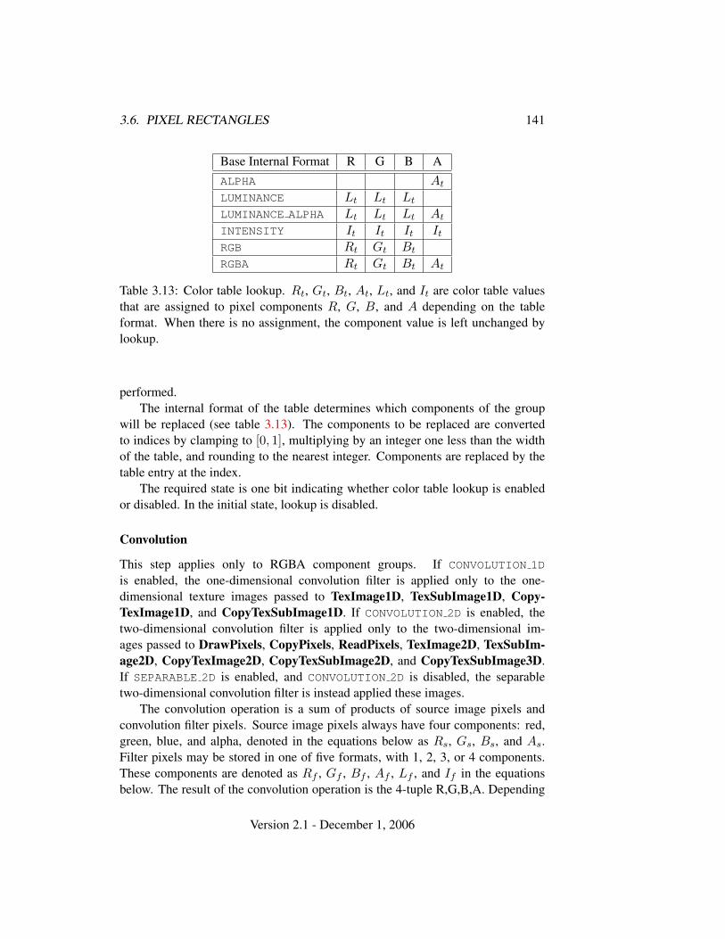
3.6. PIXEL RECTANGLES 141
Base Internal Format R G B AALPHA At
LUMINANCE Lt Lt Lt
LUMINANCE ALPHA Lt Lt Lt At
INTENSITY It It It It
RGB Rt Gt Bt
RGBA Rt Gt Bt At
Table 3.13: Color table lookup. Rt, Gt, Bt, At, Lt, and It are color table valuesthat are assigned to pixel components R, G, B, and A depending on the tableformat. When there is no assignment, the component value is left unchanged bylookup.
performed.The internal format of the table determines which components of the group
will be replaced (see table 3.13). The components to be replaced are convertedto indices by clamping to [0, 1], multiplying by an integer one less than the widthof the table, and rounding to the nearest integer. Components are replaced by thetable entry at the index.
The required state is one bit indicating whether color table lookup is enabledor disabled. In the initial state, lookup is disabled.
Convolution
This step applies only to RGBA component groups. If CONVOLUTION 1D
is enabled, the one-dimensional convolution filter is applied only to the one-dimensional texture images passed to TexImage1D, TexSubImage1D, Copy-TexImage1D, and CopyTexSubImage1D. If CONVOLUTION 2D is enabled, thetwo-dimensional convolution filter is applied only to the two-dimensional im-ages passed to DrawPixels, CopyPixels, ReadPixels, TexImage2D, TexSubIm-age2D, CopyTexImage2D, CopyTexSubImage2D, and CopyTexSubImage3D.If SEPARABLE 2D is enabled, and CONVOLUTION 2D is disabled, the separabletwo-dimensional convolution filter is instead applied these images.
The convolution operation is a sum of products of source image pixels andconvolution filter pixels. Source image pixels always have four components: red,green, blue, and alpha, denoted in the equations below as Rs, Gs, Bs, and As.Filter pixels may be stored in one of five formats, with 1, 2, 3, or 4 components.These components are denoted as Rf , Gf , Bf , Af , Lf , and If in the equationsbelow. The result of the convolution operation is the 4-tuple R,G,B,A. Depending
Version 2.1 - December 1, 2006
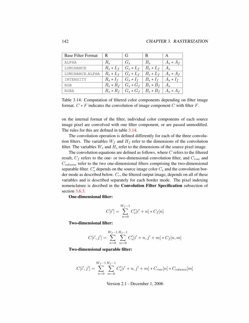
142 CHAPTER 3. RASTERIZATION
Base Filter Format R G B AALPHA Rs Gs Bs As ∗Af
LUMINANCE Rs ∗ Lf Gs ∗ Lf Bs ∗ Lf As
LUMINANCE ALPHA Rs ∗ Lf Gs ∗ Lf Bs ∗ Lf As ∗Af
INTENSITY Rs ∗ If Gs ∗ If Bs ∗ If As ∗ If
RGB Rs ∗Rf Gs ∗Gf Bs ∗Bf As
RGBA Rs ∗Rf Gs ∗Gf Bs ∗Bf As ∗Af
Table 3.14: Computation of filtered color components depending on filter imageformat. C ∗ F indicates the convolution of image component C with filter F .
on the internal format of the filter, individual color components of each sourceimage pixel are convolved with one filter component, or are passed unmodified.The rules for this are defined in table 3.14.
The convolution operation is defined differently for each of the three convolu-tion filters. The variables Wf and Hf refer to the dimensions of the convolutionfilter. The variables Ws and Hs refer to the dimensions of the source pixel image.
The convolution equations are defined as follows, where C refers to the filteredresult, Cf refers to the one- or two-dimensional convolution filter, and Crow andCcolumn refer to the two one-dimensional filters comprising the two-dimensionalseparable filter. C ′
s depends on the source image color Cs and the convolution bor-der mode as described below. Cr, the filtered output image, depends on all of thesevariables and is described separately for each border mode. The pixel indexingnomenclature is decribed in the Convolution Filter Specification subsection ofsection 3.6.3.
One-dimensional filter:
C[i′] =Wf−1∑n=0
C ′s[i
′ + n] ∗ Cf [n]
Two-dimensional filter:
C[i′, j′] =Wf−1∑n=0
Hf−1∑m=0
C ′s[i
′ + n, j′ + m] ∗ Cf [n, m]
Two-dimensional separable filter:
C[i′, j′] =Wf−1∑n=0
Hf−1∑m=0
C ′s[i
′ + n, j′ + m] ∗ Crow[n] ∗ Ccolumn[m]
Version 2.1 - December 1, 2006
3.6. PIXEL RECTANGLES 143
If Wf of a one-dimensional filter is zero, then C[i] is always set to zero. Like-wise, if either Wf or Hf of a two-dimensional filter is zero, then C[i, j] is alwaysset to zero.
The convolution border mode for a specific convolution filter is specified bycalling
void ConvolutionParameter{if}( enum target, enum pname,T param );
where target is the name of the filter, pname is CONVOLUTION BORDER MODE, andparam is one of REDUCE, CONSTANT BORDER or REPLICATE BORDER.
Border Mode REDUCE
The width and height of source images convolved with border mode REDUCE arereduced by Wf − 1 and Hf − 1, respectively. If this reduction would generatea resulting image with zero or negative width and/or height, the output is simplynull, with no error generated. The coordinates of the image that results from a con-volution with border mode REDUCE are zero through Ws −Wf in width, and zerothrough Hs −Hf in height. In cases where errors can result from the specificationof invalid image dimensions, it is these resulting dimensions that are tested, notthe dimensions of the source image. (A specific example is TexImage1D and Tex-Image2D, which specify constraints for image dimensions. Even if TexImage1Dor TexImage2D is called with a null pixel pointer, the dimensions of the result-ing texture image are those that would result from the convolution of the specifiedimage).
When the border mode is REDUCE, C ′s equals the source image color Cs and
Cr equals the filtered result C.For the remaining border modes, define Cw = bWf/2c and Ch = bHf/2c.
The coordinates (Cw, Ch) define the center of the convolution filter.
Border Mode CONSTANT BORDER
If the convolution border mode is CONSTANT BORDER, the output image has thesame dimensions as the source image. The result of the convolution is the sameas if the source image were surrounded by pixels with the same color as thecurrent convolution border color. Whenever the convolution filter extends be-yond one of the edges of the source image, the constant-color border pixels areused as input to the filter. The current convolution border color is set by call-ing ConvolutionParameterfv or ConvolutionParameteriv with pname set toCONVOLUTION BORDER COLOR and params containing four values that comprise
Version 2.1 - December 1, 2006
144 CHAPTER 3. RASTERIZATION
the RGBA color to be used as the image border. Integer color components areinterpreted linearly such that the most positive integer maps to 1.0, and the mostnegative integer maps to -1.0. Floating point color components are not clampedwhen they are specified.
For a one-dimensional filter, the result color is defined by
Cr[i] = C[i− Cw]
where C[i′] is computed using the following equation for C ′s[i
′]:
C ′s[i
′] =
{Cs[i′], 0 ≤ i′ < Ws
Cc, otherwise
and Cc is the convolution border color.For a two-dimensional or two-dimensional separable filter, the result color is
defined by
Cr[i, j] = C[i− Cw, j − Ch]
where C[i′, j′] is computed using the following equation for C ′s[i
′, j′]:
C ′s[i
′, j′] =
{Cs[i′, j′], 0 ≤ i′ < Ws, 0 ≤ j′ < Hs
Cc, otherwise
Border Mode REPLICATE BORDER
The convolution border mode REPLICATE BORDER also produces an output im-age with the same dimensions as the source image. The behavior of this mode isidentical to that of the CONSTANT BORDER mode except for the treatment of pixellocations where the convolution filter extends beyond the edge of the source im-age. For these locations, it is as if the outermost one-pixel border of the sourceimage was replicated. Conceptually, each pixel in the leftmost one-pixel columnof the source image is replicated Cw times to provide additional image data alongthe left edge, each pixel in the rightmost one-pixel column is replicated Cw timesto provide additional image data along the right edge, and each pixel value in thetop and bottom one-pixel rows is replicated to create Ch rows of image data alongthe top and bottom edges. The pixel value at each corner is also replicated in orderto provide data for the convolution operation at each corner of the source image.
For a one-dimensional filter, the result color is defined by
Cr[i] = C[i− Cw]
Version 2.1 - December 1, 2006
3.6. PIXEL RECTANGLES 145
where C[i′] is computed using the following equation for C ′s[i
′]:
C ′s[i
′] = Cs[clamp(i′,Ws)]
and the clamping function clamp(val, max) is defined as
clamp(val, max) =
0, val < 0val, 0 ≤ val < maxmax− 1, val ≥ max
For a two-dimensional or two-dimensional separable filter, the result color isdefined by
Cr[i, j] = C[i− Cw, j − Ch]
where C[i′, j′] is computed using the following equation for C ′s[i
′, j′]:
C ′s[i
′, j′] = Cs[clamp(i′,Ws), clamp(j′,Hs)]
If a convolution operation is performed, each component ofthe resulting image is scaled by the corresponding PixelTrans-fer parameters: POST CONVOLUTION RED SCALE for an R com-ponent, POST CONVOLUTION GREEN SCALE for a G compo-nent, POST CONVOLUTION BLUE SCALE for a B component, andPOST CONVOLUTION ALPHA SCALE for an A component. The resultis added to the corresponding bias: POST CONVOLUTION RED BIAS,POST CONVOLUTION GREEN BIAS, POST CONVOLUTION BLUE BIAS, orPOST CONVOLUTION ALPHA BIAS.
The required state is three bits indicating whether each of one-dimensional,two-dimensional, or separable two-dimensional convolution is enabled or disabled,an integer describing the current convolution border mode, and four floating-pointvalues specifying the convolution border color. In the initial state, all convolu-tion operations are disabled, the border mode is REDUCE, and the border color is(0, 0, 0, 0).
Post Convolution Color Table Lookup
This step applies only to RGBA component groups. Post convolution colortable lookup is enabled or disabled by calling Enable or Disable withthe symbolic constant POST CONVOLUTION COLOR TABLE. The post convo-lution table is defined by calling ColorTable with a target argument of
Version 2.1 - December 1, 2006
146 CHAPTER 3. RASTERIZATION
POST CONVOLUTION COLOR TABLE. In all other respects, operation is identicalto color table lookup, as defined earlier in section 3.6.5.
The required state is one bit indicating whether post convolution table lookupis enabled or disabled. In the initial state, lookup is disabled.
Color Matrix Transformation
This step applies only to RGBA component groups. The components aretransformed by the color matrix. Each transformed component is multipliedby an appropriate signed scale factor: POST COLOR MATRIX RED SCALE
for an R component, POST COLOR MATRIX GREEN SCALE for a Gcomponent, POST COLOR MATRIX BLUE SCALE for a B component,and POST COLOR MATRIX ALPHA SCALE for an A component. Theresult is added to a signed bias: POST COLOR MATRIX RED BIAS,POST COLOR MATRIX GREEN BIAS, POST COLOR MATRIX BLUE BIAS, orPOST COLOR MATRIX ALPHA BIAS. The resulting components replace eachcomponent of the original group.
That is, if Mc is the color matrix, a subscript of s represents the scale term fora component, and a subscript of b represents the bias term, then the components
RGBA
are transformed to
R′
G′
B′
A′
=
Rs 0 0 00 Gs 0 00 0 Bs 00 0 0 As
Mc
RGBA
+
Rb
Gb
Bb
Ab
.
Post Color Matrix Color Table Lookup
This step applies only to RGBA component groups. Post color matrixcolor table lookup is enabled or disabled by calling Enable or Disablewith the symbolic constant POST COLOR MATRIX COLOR TABLE. The post colormatrix table is defined by calling ColorTable with a target argument ofPOST COLOR MATRIX COLOR TABLE. In all other respects, operation is identicalto color table lookup, as defined in section 3.6.5.
The required state is one bit indicating whether post color matrix lookup isenabled or disabled. In the initial state, lookup is disabled.
Version 2.1 - December 1, 2006

3.6. PIXEL RECTANGLES 147
Histogram
This step applies only to RGBA component groups. Histogram operation isenabled or disabled by calling Enable or Disable with the symbolic constantHISTOGRAM.
If the width of the table is non-zero, then indices Ri, Gi, Bi, and Ai are de-rived from the red, green, blue, and alpha components of each pixel group (withoutmodifying these components) by clamping each component to [0, 1] , multiplyingby one less than the width of the histogram table, and rounding to the nearest in-teger. If the format of the HISTOGRAM table includes red or luminance, the red orluminance component of histogram entry Ri is incremented by one. If the formatof the HISTOGRAM table includes green, the green component of histogram entryGi is incremented by one. The blue and alpha components of histogram entriesBi and Ai are incremented in the same way. If a histogram entry component isincremented beyond its maximum value, its value becomes undefined; this is notan error.
If the Histogram sink parameter is FALSE, histogram operation has no effecton the stream of pixel groups being processed. Otherwise, all RGBA pixel groupsare discarded immediately after the histogram operation is completed. Becausehistogram precedes minmax, no minmax operation is performed. No pixel frag-ments are generated, no change is made to texture memory contents, and no pixelvalues are returned. However, texture object state is modified whether or not pixelgroups are discarded.
Minmax
This step applies only to RGBA component groups. Minmax operation is enabledor disabled by calling Enable or Disable with the symbolic constant MINMAX.
If the format of the minmax table includes red or luminance, the red compo-nent value replaces the red or luminance value in the minimum table element ifand only if it is less than that component. Likewise, if the format includes red orluminance and the red component of the group is greater than the red or luminancevalue in the maximum element, the red group component replaces the red or lumi-nance maximum component. If the format of the table includes green, the greengroup component conditionally replaces the green minimum and/or maximum ifit is smaller or larger, respectively. The blue and alpha group components aresimilarly tested and replaced, if the table format includes blue and/or alpha. Theinternal type of the minimum and maximum component values is floating point,with at least the same representable range as a floating point number used to rep-resent colors (section 2.1.1). There are no semantics defined for the treatment of
Version 2.1 - December 1, 2006
148 CHAPTER 3. RASTERIZATION
group component values that are outside the representable range.If the Minmax sink parameter is FALSE, minmax operation has no effect on
the stream of pixel groups being processed. Otherwise, all RGBA pixel groups arediscarded immediately after the minmax operation is completed. No pixel frag-ments are generated, no change is made to texture memory contents, and no pixelvalues are returned. However, texture object state is modified whether or not pixelgroups are discarded.
3.6.6 Pixel Rectangle Multisample Rasterization
If MULTISAMPLE is enabled, and the value of SAMPLE BUFFERS is one, then pixelrectangles are rasterized using the following algorithm. Let (Xrp, Yrp) be the cur-rent raster position. (If the current raster position is invalid, then DrawPixels isignored.) If a particular group (index or components) is the nth in a row and be-longs to the mth row, consider the region in window coordinates bounded by therectangle with corners
(Xrp + Zx ∗ n, Yrp + Zy ∗m)
and(Xrp + Zx ∗ (n + 1), Yrp + Zy ∗ (m + 1))
where Zx and Zy are the pixel zoom factors specified by PixelZoom, and may eachbe either positive or negative. A fragment representing group (n, m) is producedfor each framebuffer pixel with one or more sample points that lie inside, or onthe bottom or left boundary, of this rectangle. Each fragment so produced takes itsassociated data from the group and from the current raster position, in a mannerconsistent with the discussion in the Conversion to Fragments subsection of sec-tion 3.6.4. All depth and color sample values are assigned the same value, takeneither from their group (for depth and color component groups) or from the cur-rent raster position (if they are not). All sample values are assigned the same fogcoordinate and the same set of texture coordinates, taken from the current rasterposition.
A single pixel rectangle will generate multiple, perhaps very many fragmentsfor the same framebuffer pixel, depending on the pixel zoom factors.
3.7 Bitmaps
Bitmaps are rectangles of zeros and ones specifying a particular pattern of frag-ments to be produced. Each of these fragments has the same associated data. Thesedata are those associated with the current raster position.
Version 2.1 - December 1, 2006
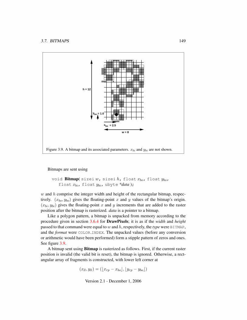
3.7. BITMAPS 149
� � �� � �� � �
� � �� � �� � �� � �
� � �� � �
� � �� � �� � �
� � �� � �� � �
� � �� � �� � �� � �
� � �� � �
� � �� � �� � �� � �
� � �� � �
� � �� � �� � �� � �
� � �� � �
� � �� � �� � �
� � �� � �� � �� � �
� � �� � �
� � �� � �� � �
� � �� � �� � �� � �
� � �� � �
� � �� � �� � �� � �
� � �� � �
� � �� � �� � �� � �� � �� � �
� � �� � �� � �
� � �� � �� � �
� � �� � �� � �
� � �� � �� � �
� � �� � �� � � � � �
� � �� � �
� � �� � �� � �
� � �� � �� � �
! ! !! ! !! ! !
" " "" " "" " "
# # ## # ## # #
$ $ $$ $ $$ $ $
% % %% % %% % %
& & && & && & &
' ' '' ' '' ' '
h = 12
w = 8
ybo = 1.0
xbo = 2.5
Figure 3.9. A bitmap and its associated parameters. xbi and ybi are not shown.
Bitmaps are sent using
void Bitmap( sizei w, sizei h, float xbo, float ybo,float xbi, float ybi, ubyte *data );
w and h comprise the integer width and height of the rectangular bitmap, respec-tively. (xbo, ybo) gives the floating-point x and y values of the bitmap’s origin.(xbi, ybi) gives the floating-point x and y increments that are added to the rasterposition after the bitmap is rasterized. data is a pointer to a bitmap.
Like a polygon pattern, a bitmap is unpacked from memory according to theprocedure given in section 3.6.4 for DrawPixels; it is as if the width and heightpassed to that command were equal to w and h, respectively, the type were BITMAP,and the format were COLOR INDEX. The unpacked values (before any conversionor arithmetic would have been performed) form a stipple pattern of zeros and ones.See figure 3.9.
A bitmap sent using Bitmap is rasterized as follows. First, if the current rasterposition is invalid (the valid bit is reset), the bitmap is ignored. Otherwise, a rect-angular array of fragments is constructed, with lower left corner at
(xll, yll) = (bxrp − xboc, byrp − yboc)
Version 2.1 - December 1, 2006
150 CHAPTER 3. RASTERIZATION
and upper right corner at (xll+w, yll+h) where w and h are the width and height ofthe bitmap, respectively. Fragments in the array are produced if the correspondingbit in the bitmap is 1 and not produced otherwise. The associated data for eachfragment are those associated with the current raster position. Once the fragmentshave been produced, the current raster position is updated:
(xrp, yrp)← (xrp + xbi, yrp + ybi).
The z and w values of the current raster position remain unchanged.
Bitmap Multisample Rasterization
If MULTISAMPLE is enabled, and the value of SAMPLE BUFFERS is one, thenbitmaps are rasterized using the following algorithm. If the current raster positionis invalid, the bitmap is ignored. Otherwise, a screen-aligned array of pixel-sizerectangles is constructed, with its lower left corner at (Xrp, Yrp), and its upperright corner at (Xrp + w, Yrp + h), where w and h are the width and height ofthe bitmap. Rectangles in this array are eliminated if the corresponding bit in thebitmap is 0, and are retained otherwise. Bitmap rasterization produces a fragmentfor each framebuffer pixel with one or more sample points either inside or on thebottom or left edge of a retained rectangle.
Coverage bits that correspond to sample points either inside or on the bottomor left edge of a retained rectangle are 1, other coverage bits are 0. The associateddata for each sample are those associated with the current raster position. Once thefragments have been produced, the current raster position is updated exactly as itis in the single-sample rasterization case.
3.8 Texturing
Texturing maps a portion of one or more specified images onto each primitive forwhich texturing is enabled. This mapping is accomplished by using the color of animage at the location indicated by a texture coordinate set’s (s, t, r, q) cordinates.
Implementations must support texturing using at least two images at a time.Each fragment or vertex carries multiple sets of texture coordinates (s, t, r, q)which are used to index separate images to produce color values which are collec-tively used to modify the resulting transformed vertex or fragment color. Texturingis specified only for RGBA mode; its use in color index mode is undefined. Thefollowing subsections (up to and including section 3.8.8) specify the GL operationwith a single texture and section 3.8.16 specifies the details of how multiple textureunits interact.
Version 2.1 - December 1, 2006
3.8. TEXTURING 151
The GL provides two ways to specify the details of how texturing of a prim-itive is effected. The first is referred to as fixed-functionality, and is described inthis section. The second is referred to as a fragment shader, and is described insection 3.11. The specification of the image to be texture mapped and the meansby which the image is filtered when applied to the primitive are common to bothmethods and are discussed in this section. The fixed functionality method for de-termining what RGBA value is produced is also described in this section. If afragment shader is active, the method for determining the RGBA value is specifiedby an application-supplied fragment shader as described in the OpenGL ShadingLanguage Specification.
When no fragment shader is active, the coordinates used for texturing are(s/q, t/q, r/q), derived from the original texture coordinates (s, t, r, q). If the qtexture coordinate is less than or equal to zero, the coordinates used for texturingare undefined. When a fragment shader is active, the (s, t, r, q) coordinates areavailable to the fragment shader. The coordinates used for texturing in a fragmentshader are defined by the OpenGL Shading Language Specification.
3.8.1 Texture Image Specification
The command
void TexImage3D( enum target, int level, int internalformat,sizei width, sizei height, sizei depth, int border,enum format, enum type, void *data );
is used to specify a three-dimensional texture image. target must be ei-ther TEXTURE 3D, or PROXY TEXTURE 3D in the special case discussed in sec-tion 3.8.11. format, type, and data match the corresponding arguments to Draw-Pixels (refer to section 3.6.4); they specify the format of the image data, the type ofthose data, and a reference to the image data in the currently bound pixel unpackbuffer or client memory. The format STENCIL INDEX is not allowed.
The groups in memory are treated as being arranged in a sequence of ad-jacent rectangles. Each rectangle is a two-dimensional image, whose size andorganization are specified by the width and height parameters to TexImage3D.The values of UNPACK ROW LENGTH and UNPACK ALIGNMENT control the row-to-row spacing in these images in the same manner as DrawPixels. If the value ofthe integer parameter UNPACK IMAGE HEIGHT is not positive, then the numberof rows in each two-dimensional image is height; otherwise the number of rowsis UNPACK IMAGE HEIGHT. Each two-dimensional image comprises an integralnumber of rows, and is exactly adjacent to its neighbor images.
Version 2.1 - December 1, 2006
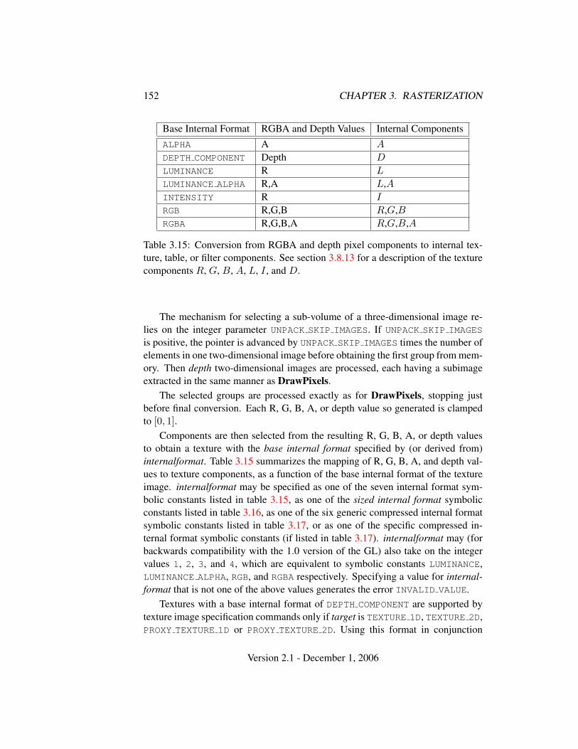
152 CHAPTER 3. RASTERIZATION
Base Internal Format RGBA and Depth Values Internal ComponentsALPHA A A
DEPTH COMPONENT Depth D
LUMINANCE R L
LUMINANCE ALPHA R,A L,AINTENSITY R I
RGB R,G,B R,G,BRGBA R,G,B,A R,G,B,A
Table 3.15: Conversion from RGBA and depth pixel components to internal tex-ture, table, or filter components. See section 3.8.13 for a description of the texturecomponents R, G, B, A, L, I , and D.
The mechanism for selecting a sub-volume of a three-dimensional image re-lies on the integer parameter UNPACK SKIP IMAGES. If UNPACK SKIP IMAGES
is positive, the pointer is advanced by UNPACK SKIP IMAGES times the number ofelements in one two-dimensional image before obtaining the first group from mem-ory. Then depth two-dimensional images are processed, each having a subimageextracted in the same manner as DrawPixels.
The selected groups are processed exactly as for DrawPixels, stopping justbefore final conversion. Each R, G, B, A, or depth value so generated is clampedto [0, 1].
Components are then selected from the resulting R, G, B, A, or depth valuesto obtain a texture with the base internal format specified by (or derived from)internalformat. Table 3.15 summarizes the mapping of R, G, B, A, and depth val-ues to texture components, as a function of the base internal format of the textureimage. internalformat may be specified as one of the seven internal format sym-bolic constants listed in table 3.15, as one of the sized internal format symbolicconstants listed in table 3.16, as one of the six generic compressed internal formatsymbolic constants listed in table 3.17, or as one of the specific compressed in-ternal format symbolic constants (if listed in table 3.17). internalformat may (forbackwards compatibility with the 1.0 version of the GL) also take on the integervalues 1, 2, 3, and 4, which are equivalent to symbolic constants LUMINANCE,LUMINANCE ALPHA, RGB, and RGBA respectively. Specifying a value for internal-format that is not one of the above values generates the error INVALID VALUE.
Textures with a base internal format of DEPTH COMPONENT are supported bytexture image specification commands only if target is TEXTURE 1D, TEXTURE 2D,PROXY TEXTURE 1D or PROXY TEXTURE 2D. Using this format in conjunction
Version 2.1 - December 1, 2006
3.8. TEXTURING 153
with any other target will result in an INVALID OPERATION error.Textures with a base internal format of DEPTH COMPONENT require depth com-
ponent data; textures with other base internal formats require RGBA componentdata. The error INVALID OPERATION is generated if the base internal format isDEPTH COMPONENT and format is not DEPTH COMPONENT, or if the base internalformat is not DEPTH COMPONENT and format is DEPTH COMPONENT.
The GL provides no specific compressed internal formats but does provide amechanism to obtain token values for such formats provided by extensions. Thenumber of specific compressed internal formats supported by the renderer canbe obtained by querying the value of NUM COMPRESSED TEXTURE FORMATS. Theset of specific compressed internal formats supported by the renderer can be ob-tained by querying the value of COMPRESSED TEXTURE FORMATS. The only val-ues returned by this query are those corresponding to formats suitable for general-purpose usage. The renderer will not enumerate formats with restrictions that needto be specifically understood prior to use.
Generic compressed internal formats are never used directly as the internal for-mats of texture images. If internalformat is one of the six generic compressedinternal formats, its value is replaced by the symbolic constant for a specific com-pressed internal format of the GL’s choosing with the same base internal format.If no specific compressed format is available, internalformat is instead replaced bythe corresponding base internal format. If internalformat is given as or mappedto a specific compressed internal format, but the GL can not support images com-pressed in the chosen internal format for any reason (e.g., the compression formatmight not support 3D textures or borders), internalformat is replaced by the corre-sponding base internal format and the texture image will not be compressed by theGL.
The internal component resolution is the number of bits allocated to each valuein a texture image. If internalformat is specified as a base internal format, the GLstores the resulting texture with internal component resolutions of its own choos-ing. If a sized internal format is specified, the mapping of the R, G, B, A, anddepth values to texture components is equivalent to the mapping of the correspond-ing base internal format’s components, as specified in table 3.15, and the memoryallocation per texture component is assigned by the GL to match the allocationslisted in table 3.16 as closely as possible. (The definition of closely is left up to theimplementation. However, a non-zero number of bits must be allocated for eachcomponent whose desired allocation in table 3.16 is non-zero, and zero bits mustbe allocated for all other components). Implementations are required to support atleast one allocation of internal component resolution for each base internal format.
Version 2.1 - December 1, 2006
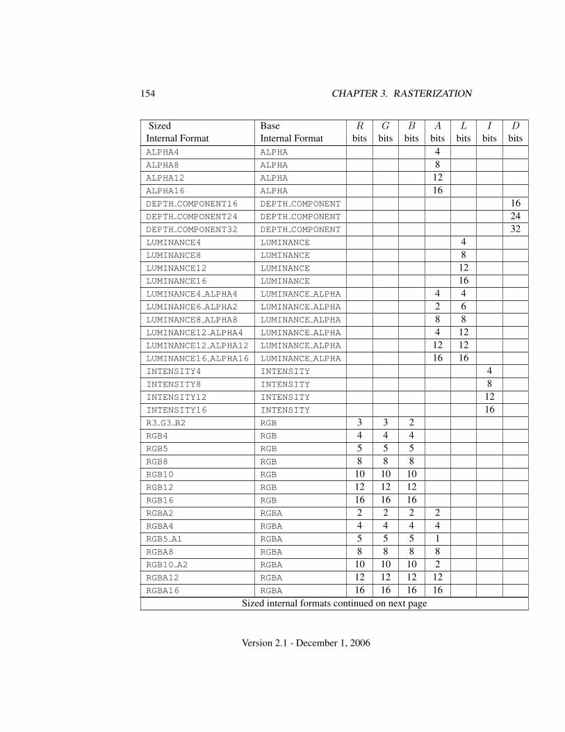
154 CHAPTER 3. RASTERIZATION
Sized Base R G B A L I DInternal Format Internal Format bits bits bits bits bits bits bitsALPHA4 ALPHA 4ALPHA8 ALPHA 8ALPHA12 ALPHA 12ALPHA16 ALPHA 16DEPTH COMPONENT16 DEPTH COMPONENT 16DEPTH COMPONENT24 DEPTH COMPONENT 24DEPTH COMPONENT32 DEPTH COMPONENT 32LUMINANCE4 LUMINANCE 4LUMINANCE8 LUMINANCE 8LUMINANCE12 LUMINANCE 12LUMINANCE16 LUMINANCE 16LUMINANCE4 ALPHA4 LUMINANCE ALPHA 4 4LUMINANCE6 ALPHA2 LUMINANCE ALPHA 2 6LUMINANCE8 ALPHA8 LUMINANCE ALPHA 8 8LUMINANCE12 ALPHA4 LUMINANCE ALPHA 4 12LUMINANCE12 ALPHA12 LUMINANCE ALPHA 12 12LUMINANCE16 ALPHA16 LUMINANCE ALPHA 16 16INTENSITY4 INTENSITY 4INTENSITY8 INTENSITY 8INTENSITY12 INTENSITY 12INTENSITY16 INTENSITY 16R3 G3 B2 RGB 3 3 2RGB4 RGB 4 4 4RGB5 RGB 5 5 5RGB8 RGB 8 8 8RGB10 RGB 10 10 10RGB12 RGB 12 12 12RGB16 RGB 16 16 16RGBA2 RGBA 2 2 2 2RGBA4 RGBA 4 4 4 4RGB5 A1 RGBA 5 5 5 1RGBA8 RGBA 8 8 8 8RGB10 A2 RGBA 10 10 10 2RGBA12 RGBA 12 12 12 12RGBA16 RGBA 16 16 16 16
Sized internal formats continued on next page
Version 2.1 - December 1, 2006
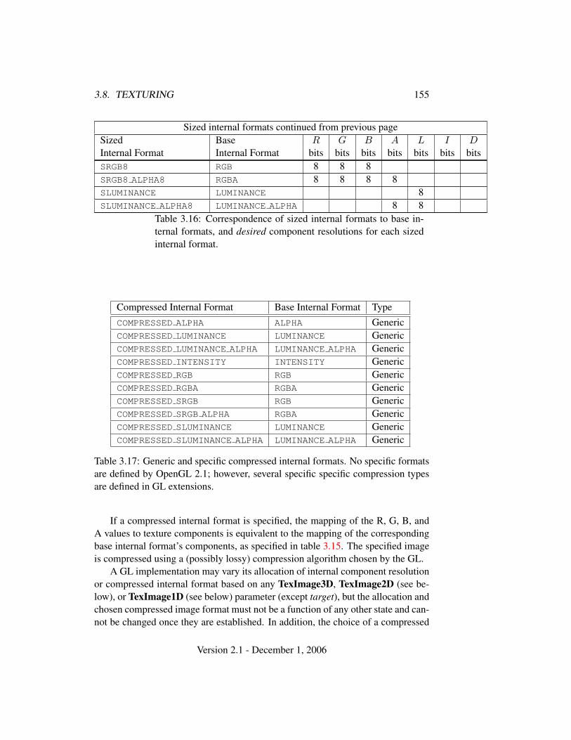
3.8. TEXTURING 155
Sized internal formats continued from previous pageSized Base R G B A L I DInternal Format Internal Format bits bits bits bits bits bits bitsSRGB8 RGB 8 8 8SRGB8 ALPHA8 RGBA 8 8 8 8SLUMINANCE LUMINANCE 8SLUMINANCE ALPHA8 LUMINANCE ALPHA 8 8
Table 3.16: Correspondence of sized internal formats to base in-ternal formats, and desired component resolutions for each sizedinternal format.
Compressed Internal Format Base Internal Format TypeCOMPRESSED ALPHA ALPHA GenericCOMPRESSED LUMINANCE LUMINANCE GenericCOMPRESSED LUMINANCE ALPHA LUMINANCE ALPHA GenericCOMPRESSED INTENSITY INTENSITY GenericCOMPRESSED RGB RGB GenericCOMPRESSED RGBA RGBA GenericCOMPRESSED SRGB RGB GenericCOMPRESSED SRGB ALPHA RGBA GenericCOMPRESSED SLUMINANCE LUMINANCE GenericCOMPRESSED SLUMINANCE ALPHA LUMINANCE ALPHA Generic
Table 3.17: Generic and specific compressed internal formats. No specific formatsare defined by OpenGL 2.1; however, several specific specific compression typesare defined in GL extensions.
If a compressed internal format is specified, the mapping of the R, G, B, andA values to texture components is equivalent to the mapping of the correspondingbase internal format’s components, as specified in table 3.15. The specified imageis compressed using a (possibly lossy) compression algorithm chosen by the GL.
A GL implementation may vary its allocation of internal component resolutionor compressed internal format based on any TexImage3D, TexImage2D (see be-low), or TexImage1D (see below) parameter (except target), but the allocation andchosen compressed image format must not be a function of any other state and can-not be changed once they are established. In addition, the choice of a compressed
Version 2.1 - December 1, 2006
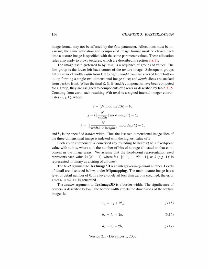
156 CHAPTER 3. RASTERIZATION
image format may not be affected by the data parameter. Allocations must be in-variant; the same allocation and compressed image format must be chosen eachtime a texture image is specified with the same parameter values. These allocationrules also apply to proxy textures, which are described in section 3.8.11.
The image itself (referred to by data) is a sequence of groups of values. Thefirst group is the lower left back corner of the texture image. Subsequent groupsfill out rows of width width from left to right; height rows are stacked from bottomto top forming a single two-dimensional image slice; and depth slices are stackedfrom back to front. When the final R, G, B, and A components have been computedfor a group, they are assigned to components of a texel as described by table 3.15.Counting from zero, each resulting N th texel is assigned internal integer coordi-nates (i, j, k), where
i = (N mod width)− bs
j = (b N
widthc mod height)− bs
k = (b N
width× heightc mod depth)− bs
and bs is the specified border width. Thus the last two-dimensional image slice ofthe three-dimensional image is indexed with the highest value of k.
Each color component is converted (by rounding to nearest) to a fixed-pointvalue with n bits, where n is the number of bits of storage allocated to that com-ponent in the image array. We assume that the fixed-point representation usedrepresents each value k/(2n − 1), where k ∈ {0, 1, . . . , 2n − 1}, as k (e.g. 1.0 isrepresented in binary as a string of all ones).
The level argument to TexImage3D is an integer level-of-detail number. Levelsof detail are discussed below, under Mipmapping. The main texture image has alevel of detail number of 0. If a level-of-detail less than zero is specified, the errorINVALID VALUE is generated.
The border argument to TexImage3D is a border width. The significance ofborders is described below. The border width affects the dimensions of the textureimage: let
ws = wt + 2bs (3.15)
hs = ht + 2bs (3.16)
ds = dt + 2bs (3.17)
Version 2.1 - December 1, 2006
3.8. TEXTURING 157
where ws, hs, and ds are the specified image width, depth, and depth, and wt,ht, and dt are the dimensions of the texture image internal to the border. If wt, ht,or dt are less than zero, then the error INVALID VALUE is generated.
An image with zero width, height, or depth indicates the null texture. Ifthe null texture is specified for the level-of-detail specified by texture parameterTEXTURE BASE LEVEL (see section 3.8.4), it is as if texturing were disabled.
Currently, the maximum border width bt is 1. If bs is less than zero, or greaterthan bt, then the error INVALID VALUE is generated.
The maximum allowable width, height, or depth of a three-dimensional textureimage is an implementation dependent function of the level-of-detail and internalformat of the resulting image array. It must be at least 2k−lod+2bt for image arraysof level-of-detail 0 through k, where k is the log base 2 of MAX 3D TEXTURE SIZE,lod is the level-of-detail of the image array, and bt is the maximum border width.It may be zero for image arrays of any level-of-detail greater than k. The errorINVALID VALUE is generated if the specified image is too large to be stored underany conditions.
If a pixel unpack buffer object is bound and storing texture data would accessmemory beyond the end of the pixel unpack buffer, an INVALID OPERATION errorresults.
In a similar fashion, the maximum allowable width of a one- or two-dimensional texture image, and the maximum allowable height of a two-dimensional texture image, must be at least 2k−lod + 2bt for image arrays of level0 through k, where k is the log base 2 of MAX TEXTURE SIZE. The maximum al-lowable width and height of a cube map texture must be the same, and must be atleast 2k−lod + 2bt for image arrays level 0 through k, where k is the log base 2 ofMAX CUBE MAP TEXTURE SIZE.
An implementation may allow an image array of level 0 to be created only ifthat single image array can be supported. Additional constraints on the creation ofimage arrays of level 1 or greater are described in more detail in section 3.8.10.
The command
void TexImage2D( enum target, int level,int internalformat, sizei width, sizei height,int border, enum format, enum type, void *data );
is used to specify a two-dimensional texture image. target mustbe one of TEXTURE 2D for a two-dimensional texture, or one ofTEXTURE CUBE MAP POSITIVE X, TEXTURE CUBE MAP NEGATIVE X,TEXTURE CUBE MAP POSITIVE Y, TEXTURE CUBE MAP NEGATIVE Y,TEXTURE CUBE MAP POSITIVE Z, or TEXTURE CUBE MAP NEGATIVE Z for
Version 2.1 - December 1, 2006
158 CHAPTER 3. RASTERIZATION
a cube map texture. Additionally, target may be either PROXY TEXTURE 2D fora two-dimensional proxy texture or PROXY TEXTURE CUBE MAP for a cube mapproxy texture in the special case discussed in section 3.8.11. The other parametersmatch the corresponding parameters of TexImage3D.
For the purposes of decoding the texture image, TexImage2D is equivalent tocalling TexImage3D with corresponding arguments and depth of 1, except that
• The depth of the image is always 1 regardless of the value of border.
• Convolution will be performed on the image (possibly changing its widthand height) if SEPARABLE 2D or CONVOLUTION 2D is enabled.
• UNPACK SKIP IMAGES is ignored.
A two-dimensional texture consists of a single two-dimensional texture image.A cube map texture is a set of six two-dimensional texture images. The six cubemap texture targets form a single cube map texture though each target names adistinct face of the cube map. The TEXTURE CUBE MAP * targets listed above up-date their appropriate cube map face 2D texture image. Note that the six cube maptwo-dimensional image tokens such as TEXTURE CUBE MAP POSITIVE X are usedwhen specifying, updating, or querying one of a cube map’s six two-dimensionalimages, but when enabling cube map texturing or binding to a cube map textureobject (that is when the cube map is accessed as a whole as opposed to a particulartwo-dimensional image), the TEXTURE CUBE MAP target is specified.
When the target parameter to TexImage2D is one of the six cube map two-dimensional image targets, the error INVALID VALUE is generated if the width andheight parameters are not equal.
Finally, the command
void TexImage1D( enum target, int level,int internalformat, sizei width, int border,enum format, enum type, void *data );
is used to specify a one-dimensional texture image. target must be eitherTEXTURE 1D, or PROXY TEXTURE 1D in the special case discussed in sec-tion 3.8.11.)
For the purposes of decoding the texture image, TexImage1D is equivalent tocalling TexImage2D with corresponding arguments and height of 1, except that
• The height of the image is always 1 regardless of the value of border.
Version 2.1 - December 1, 2006
3.8. TEXTURING 159
• Convolution will be performed on the image (possibly changing its width)only if CONVOLUTION 1D is enabled.
The image indicated to the GL by the image pointer is decoded and copied intothe GL’s internal memory. This copying effectively places the decoded image in-side a border of the maximum allowable width bt whether or not a border has beenspecified (see figure 3.10) 1. If no border or a border smaller than the maximumallowable width has been specified, then the image is still stored as if it were sur-rounded by a border of the maximum possible width. Any excess border (whichsurrounds the specified image, including any border) is assigned unspecified val-ues. A two-dimensional texture has a border only at its left, right, top, and bottomends, and a one-dimensional texture has a border only at its left and right ends.
We shall refer to the (possibly border augmented) decoded image as the texturearray. A three-dimensional texture array has width, height, and depth ws, hs, andds as defined respectively in equations 3.15, 3.16, and 3.17. A two-dimensionaltexture array has depth ds = 1, with height hs and width ws as above, and a one-dimensional texture array has depth ds = 1, height hs = 1, and width ws as above.
An element (i, j, k) of the texture array is called a texel (for a two-dimensionaltexture, k is irrelevant; for a one-dimensional texture, j and k are both irrelevant).The texture value used in texturing a fragment is determined by that fragment’sassociated (s, t, r) coordinates, but may not correspond to any actual texel. Seefigure 3.10.
If the data argument of TexImage1D, TexImage2D, or TexImage3D is a nullpointer (a zero-valued pointer in the C implementation), and the pixel unpackbuffer object is zero, a one-, two-, or three-dimensional texture array is createdwith the specified target, level, internalformat, border, width, height, and depth,but with unspecified image contents. In this case no pixel values are accessedin client memory, and no pixel processing is performed. Errors are generated,however, exactly as though the data pointer were valid. Otherwise if the pixelunpack buffer object is non-zero, the data argument is treatedly normally to referto the beginning of the pixel unpack buffer object’s data.
3.8.2 Alternate Texture Image Specification Commands
Two-dimensional and one-dimensional texture images may also be specified us-ing image data taken directly from the framebuffer, and rectangular subregions ofexisting texture images may be respecified.
The command
1 Figure 3.10 needs to show a three-dimensional texture image.
Version 2.1 - December 1, 2006
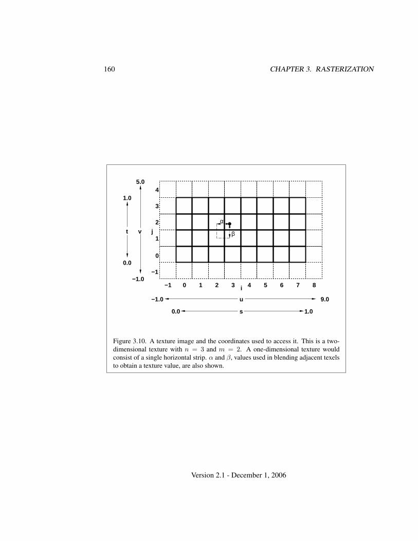
160 CHAPTER 3. RASTERIZATION
i−1 0 1 2 3 4 5 6 7 8
u−1.0 9.0
0.0 1.0s
−1
0
2
1
3
4
j
−1.0
5.0
vt
0.0
1.0
α
β
Figure 3.10. A texture image and the coordinates used to access it. This is a two-dimensional texture with n = 3 and m = 2. A one-dimensional texture wouldconsist of a single horizontal strip. α and β, values used in blending adjacent texelsto obtain a texture value, are also shown.
Version 2.1 - December 1, 2006
3.8. TEXTURING 161
void CopyTexImage2D( enum target, int level,enum internalformat, int x, int y, sizei width,sizei height, int border );
defines a two-dimensional texture array in exactly the manner of TexIm-age2D, except that the image data are taken from the framebuffer ratherthan from client memory. Currently, target must be one of TEXTURE 2D,TEXTURE CUBE MAP POSITIVE X, TEXTURE CUBE MAP NEGATIVE X,TEXTURE CUBE MAP POSITIVE Y, TEXTURE CUBE MAP NEGATIVE Y,TEXTURE CUBE MAP POSITIVE Z, or TEXTURE CUBE MAP NEGATIVE Z. x, y,width, and height correspond precisely to the corresponding arguments to CopyP-ixels (refer to section 4.3.3); they specify the image’s width and height, and thelower left (x, y) coordinates of the framebuffer region to be copied. The im-age is taken from the framebuffer exactly as if these arguments were passed toCopyPixels with argument type set to COLOR or DEPTH, depending on internal-format, stopping after pixel transfer processing is complete. RGBA data is takenfrom the current color buffer while depth component data is taken from the depthbuffer. If depth component data is required and no depth buffer is present, theerror INVALID OPERATION is generated. Subsequent processing is identical tothat described for TexImage2D, beginning with clamping of the R, G, B, A, ordepth values from the resulting pixel groups. Parameters level, internalformat, andborder are specified using the same values, with the same meanings, as the equiv-alent arguments of TexImage2D, except that internalformat may not be specifiedas 1, 2, 3, or 4. An invalid value specified for internalformat generates the errorINVALID ENUM. The constraints on width, height, and border are exactly those forthe equivalent arguments of TexImage2D.
When the target parameter to CopyTexImage2D is one of the six cube maptwo-dimensional image targets, the error INVALID VALUE is generated if the widthand height parameters are not equal.
The command
void CopyTexImage1D( enum target, int level,enum internalformat, int x, int y, sizei width,int border );
defines a one-dimensional texture array in exactly the manner of TexImage1D,except that the image data are taken from the framebuffer, rather than from clientmemory. Currently, target must be TEXTURE 1D. For the purposes of decodingthe texture image, CopyTexImage1D is equivalent to calling CopyTexImage2Dwith corresponding arguments and height of 1, except that the height of the image
Version 2.1 - December 1, 2006
162 CHAPTER 3. RASTERIZATION
is always 1, regardless of the value of border. level, internalformat, and borderare specified using the same values, with the same meanings, as the equivalentarguments of TexImage1D, except that internalformat may not be specified as 1,2, 3, or 4. The constraints on width and border are exactly those of the equivalentarguments of TexImage1D.
Six additional commands,
void TexSubImage3D( enum target, int level, int xoffset,int yoffset, int zoffset, sizei width, sizei height,sizei depth, enum format, enum type, void *data );
void TexSubImage2D( enum target, int level, int xoffset,int yoffset, sizei width, sizei height, enum format,enum type, void *data );
void TexSubImage1D( enum target, int level, int xoffset,sizei width, enum format, enum type, void *data );
void CopyTexSubImage3D( enum target, int level,int xoffset, int yoffset, int zoffset, int x, int y,sizei width, sizei height );
void CopyTexSubImage2D( enum target, int level,int xoffset, int yoffset, int x, int y, sizei width,sizei height );
void CopyTexSubImage1D( enum target, int level,int xoffset, int x, int y, sizei width );
respecify only a rectangular subregion of an existing texture array. No changeis made to the internalformat, width, height, depth, or border parametersof the specified texture array, nor is any change made to texel values out-side the specified subregion. Currently the target arguments of TexSubIm-age1D and CopyTexSubImage1D must be TEXTURE 1D, the target argumentsof TexSubImage2D and CopyTexSubImage2D must be one of TEXTURE 2D,TEXTURE CUBE MAP POSITIVE X, TEXTURE CUBE MAP NEGATIVE X,TEXTURE CUBE MAP POSITIVE Y, TEXTURE CUBE MAP NEGATIVE Y,TEXTURE CUBE MAP POSITIVE Z, or TEXTURE CUBE MAP NEGATIVE Z, and thetarget arguments of TexSubImage3D and CopyTexSubImage3D must beTEXTURE 3D. The level parameter of each command specifies the level of the tex-ture array that is modified. If level is less than zero or greater than the base 2 log-arithm of the maximum texture width, height, or depth, the error INVALID VALUE
is generated.TexSubImage3D arguments width, height, depth, format, type, and data match
the corresponding arguments to TexImage3D, meaning that they are specified us-ing the same values, and have the same meanings. Likewise, TexSubImage2D
Version 2.1 - December 1, 2006
3.8. TEXTURING 163
arguments width, height, format, type, and data match the corresponding argu-ments to TexImage2D, and TexSubImage1D arguments width, format, type, anddata match the corresponding arguments to TexImage1D.
CopyTexSubImage3D and CopyTexSubImage2D arguments x, y, width,and height match the corresponding arguments to CopyTexImage2D2. CopyTex-SubImage1D arguments x, y, and width match the corresponding arguments toCopyTexImage1D. Each of the TexSubImage commands interprets and processespixel groups in exactly the manner of its TexImage counterpart, except that the as-signment of R, G, B, A, and depth pixel group values to the texture componentsis controlled by the internalformat of the texture array, not by an argument to thecommand. The same constraints and errors apply to the TexSubImage commands’argument format and the internalformat of the texture array being respecified asapply to the format and internalformat arguments of its TexImage counterparts.
Arguments xoffset, yoffset, and zoffset of TexSubImage3D and CopyTex-SubImage3D specify the lower left texel coordinates of a width-wide by height-high by depth-deep rectangular subregion of the texture array. The depth argumentassociated with CopyTexSubImage3D is always 1, because framebuffer memoryis two-dimensional - only a portion of a single s, t slice of a three-dimensionaltexture is replaced by CopyTexSubImage3D.
Negative values of xoffset, yoffset, and zoffset correspond to the coordinatesof border texels, addressed as in figure 3.10. Taking ws, hs, ds, and bs to be thespecified width, height, depth, and border width of the texture array, and taking x,y, z, w, h, and d to be the xoffset, yoffset, zoffset, width, height, and depth argumentvalues, any of the following relationships generates the error INVALID VALUE:
x < −bs
x + w > ws − bs
y < −bs
y + h > hs − bs
z < −bs
z + d > ds − bs
Counting from zero, the nth pixel group is assigned to the texel with internal integercoordinates [i, j, k], where
i = x + (n mod w)2 Because the framebuffer is inherently two-dimensional, there is no CopyTexImage3D com-
mand.
Version 2.1 - December 1, 2006
164 CHAPTER 3. RASTERIZATION
j = y + (b nwc mod h)
k = z + (b n
width ∗ heightc mod d
Arguments xoffset and yoffset of TexSubImage2D and CopyTexSubImage2Dspecify the lower left texel coordinates of a width-wide by height-high rectangularsubregion of the texture array. Negative values of xoffset and yoffset correspond tothe coordinates of border texels, addressed as in figure 3.10. Taking ws, hs, and bs
to be the specified width, height, and border width of the texture array, and takingx, y, w, and h to be the xoffset, yoffset, width, and height argument values, any ofthe following relationships generates the error INVALID VALUE:
x < −bs
x + w > ws − bs
y < −bs
y + h > hs − bs
Counting from zero, the nth pixel group is assigned to the texel with internal integercoordinates [i, j], where
i = x + (n mod w)
j = y + (b nwc mod h)
The xoffset argument of TexSubImage1D and CopyTexSubImage1D speci-fies the left texel coordinate of a width-wide subregion of the texture array. Neg-ative values of xoffset correspond to the coordinates of border texels. Taking ws
and bs to be the specified width and border width of the texture array, and x andw to be the xoffset and width argument values, either of the following relationshipsgenerates the error INVALID VALUE:
x < −bs
x + w > ws − bs
Counting from zero, the nth pixel group is assigned to the texel with internal integercoordinates [i], where
i = x + (n mod w)
Texture images with compressed internal formats may be stored in such a waythat it is not possible to modify an image with subimage commands without having
Version 2.1 - December 1, 2006
3.8. TEXTURING 165
to decompress and recompress the texture image. Even if the image were modi-fied in this manner, it may not be possible to preserve the contents of some ofthe texels outside the region being modified. To avoid these complications, theGL does not support arbitrary modifications to texture images with compressedinternal formats. Calling TexSubImage3D, CopyTexSubImage3D, TexSubIm-age2D, CopyTexSubImage2D, TexSubImage1D, or CopyTexSubImage1D willresult in an INVALID OPERATION error if xoffset, yoffset, or zoffset is not equal to−bs (border width). In addition, the contents of any texel outside the region mod-ified by such a call are undefined. These restrictions may be relaxed for specificcompressed internal formats whose images are easily modified.
3.8.3 Compressed Texture Images
Texture images may also be specified or modified using image data already storedin a known compressed image format. The GL currently defines no such formats,but provides mechanisms for GL extensions that do.
The commands
void CompressedTexImage1D( enum target, int level,enum internalformat, sizei width, int border,sizei imageSize, void *data );
void CompressedTexImage2D( enum target, int level,enum internalformat, sizei width, sizei height,int border, sizei imageSize, void *data );
void CompressedTexImage3D( enum target, int level,enum internalformat, sizei width, sizei height,sizei depth, int border, sizei imageSize, void *data );
define one-, two-, and three-dimensional texture images, respectively, with incom-ing data stored in a specific compressed image format. The target, level, inter-nalformat, width, height, depth, and border parameters have the same meaningas in TexImage1D, TexImage2D, and TexImage3D. data refers to compressedimage data stored in the compressed image format corresponding to internal-format. If a pixel unpack buffer is bound (as indicated by a non-zero value ofPIXEL UNPACK BUFFER BINDING), data is an offset into the pixel unpack bufferand the compressed data is read from the buffer relative to this offset; otherwise,data is a pointer to client memory and the compressed data is read from clientmemory relative to the pointer. Since the GL provides no specific image formats,using any of the six generic compressed internal formats as internalformat willresult in an INVALID ENUM error.
Version 2.1 - December 1, 2006
166 CHAPTER 3. RASTERIZATION
For all other compressed internal formats, the compressed image will be de-coded according to the specification defining the internalformat token. Com-pressed texture images are treated as an array of imageSize ubytes relative todata. If a pixel unpack buffer object is bound and data + imageSize is greaterthan the size of the pixel buffer, an INVALID OPERATION error results. All pixelstorage and pixel transfer modes are ignored when decoding a compressed textureimage. If the imageSize parameter is not consistent with the format, dimensions,and contents of the compressed image, an INVALID VALUE error results. If thecompressed image is not encoded according to the defined image format, the re-sults of the call are undefined.
Specific compressed internal formats may impose format-specific restrictionson the use of the compressed image specification calls or parameters. For example,the compressed image format might be supported only for 2D textures, or mightnot allow non-zero border values. Any such restrictions will be documented in theextension specification defining the compressed internal format; violating theserestrictions will result in an INVALID OPERATION error.
Any restrictions imposed by specific compressed internal formats will beinvariant, meaning that if the GL accepts and stores a texture image incompressed form, providing the same image to CompressedTexImage1D,CompressedTexImage2D, or CompressedTexImage3D will not result in anINVALID OPERATION error if the following restrictions are satisfied:
• data points to a compressed texture image returned by GetCompressedTex-Image (section 6.1.4).
• target, level, and internalformat match the target, level and format parame-ters provided to the GetCompressedTexImage call returning data.
• width, height, depth, border, internalformat, and image-Size match the values of TEXTURE WIDTH, TEXTURE HEIGHT,TEXTURE DEPTH, TEXTURE BORDER, TEXTURE INTERNAL FORMAT,and TEXTURE COMPRESSED IMAGE SIZE for image level level in effect atthe time of the GetCompressedTexImage call returning data.
This guarantee applies not just to images returned by GetCompressedTexImage,but also to any other properly encoded compressed texture image of the same sizeand format.
The commands
void CompressedTexSubImage1D( enum target, int level,int xoffset, sizei width, enum format, sizei imageSize,void *data );
Version 2.1 - December 1, 2006
3.8. TEXTURING 167
void CompressedTexSubImage2D( enum target, int level,int xoffset, int yoffset, sizei width, sizei height,enum format, sizei imageSize, void *data );
void CompressedTexSubImage3D( enum target, int level,int xoffset, int yoffset, int zoffset, sizei width,sizei height, sizei depth, enum format,sizei imageSize, void *data );
respecify only a rectangular region of an existing texture array, with incoming datastored in a known compressed image format. The target, level, xoffset, yoffset, zoff-set, width, height, and depth parameters have the same meaning as in TexSubIm-age1D, TexSubImage2D, and TexSubImage3D. data points to compressed im-age data stored in the compressed image format corresponding to format. Sincethe core GL provides no specific image formats, using any of these six genericcompressed internal formats as format will result in an INVALID ENUM error.
The image pointed to by data and the imageSize parameter are interpretedas though they were provided to CompressedTexImage1D, CompressedTexIm-age2D, and CompressedTexImage3D. These commands do not provide for im-age format conversion, so an INVALID OPERATION error results if format doesnot match the internal format of the texture image being modified. If the image-Size parameter is not consistent with the format, dimensions, and contents of thecompressed image (too little or too much data), an INVALID VALUE error results.
As with CompressedTexImage calls, compressed internal formats may haveadditional restrictions on the use of the compressed image specification calls orparameters. Any such restrictions will be documented in the specification defin-ing the compressed internal format; violating these restrictions will result in anINVALID OPERATION error.
Any restrictions imposed by specific compressed internal formats will beinvariant, meaning that if the GL accepts and stores a texture image in com-pressed form, providing the same image to CompressedTexSubImage1D, Com-pressedTexSubImage2D, CompressedTexSubImage3D will not result in anINVALID OPERATION error if the following restrictions are satisfied:
• data points to a compressed texture image returned by GetCompressedTex-Image (section 6.1.4).
• target, level, and format match the target, level and format parameters pro-vided to the GetCompressedTexImage call returning data.
• width, height, depth, format, and imageSize match the val-ues of TEXTURE WIDTH, TEXTURE HEIGHT, TEXTURE DEPTH,
Version 2.1 - December 1, 2006
168 CHAPTER 3. RASTERIZATION
TEXTURE INTERNAL FORMAT, and TEXTURE COMPRESSED IMAGE SIZE
for image level level in effect at the time of the GetCompressedTexImagecall returning data.
• width, height, depth, format match the values of TEXTURE WIDTH,TEXTURE HEIGHT, TEXTURE DEPTH, and TEXTURE INTERNAL FORMAT
currently in effect for image level level.
• xoffset, yoffset, and zoffset are all −b, where b is the value ofTEXTURE BORDER currently in effect for image level level.
This guarantee applies not just to images returned by GetCompressedTexIm-age, but also to any other properly encoded compressed texture image of the samesize.
Calling CompressedTexSubImage3D, CompressedTexSubImage2D, orCompressedTexSubImage1D will result in an INVALID OPERATION error if xoff-set, yoffset, or zoffset is not equal to −bs (border width), or if width, height,and depth do not match the values of TEXTURE WIDTH, TEXTURE HEIGHT, orTEXTURE DEPTH, respectively. The contents of any texel outside the region modi-fied by the call are undefined. These restrictions may be relaxed for specific com-pressed internal formats whose images are easily modified.
3.8.4 Texture Parameters
Various parameters control how the texture array is treated when specified orchanged, and when applied to a fragment. Each parameter is set by calling
void TexParameter{if}( enum target, enum pname, T param );void TexParameter{if}v( enum target, enum pname,
T params );
target is the target, either TEXTURE 1D, TEXTURE 2D, TEXTURE 3D, orTEXTURE CUBE MAP. pname is a symbolic constant indicating the parameter tobe set; the possible constants and corresponding parameters are summarized in ta-ble 3.18. In the first form of the command, param is a value to which to set asingle-valued parameter; in the second form of the command, params is an arrayof parameters whose type depends on the parameter being set. If the values forTEXTURE BORDER COLOR, or the value for TEXTURE PRIORITY are specified asintegers, the conversion for signed integers from table 2.9 is applied to convertthese values to floating-point, followed by clamping each value to lie in [0, 1].
In the remainder of section 3.8, denote by lodmin, lodmax, levelbase,and levelmax the values of the texture parameters TEXTURE MIN LOD,
Version 2.1 - December 1, 2006
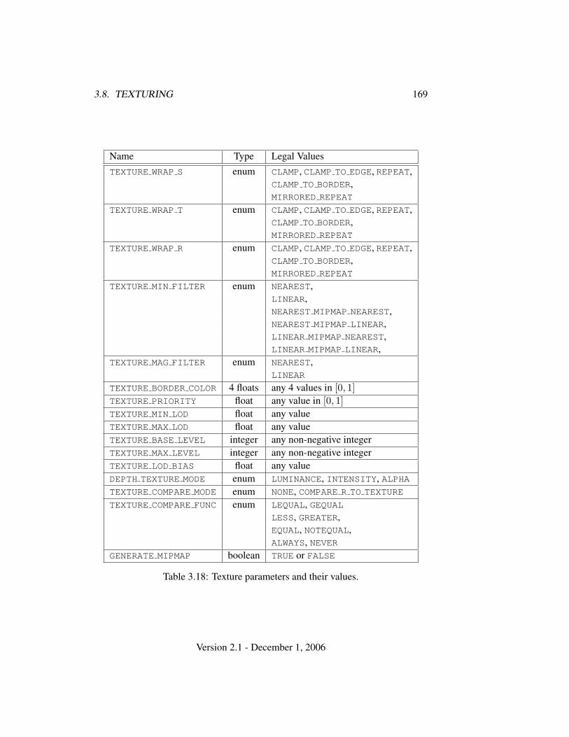
3.8. TEXTURING 169
Name Type Legal ValuesTEXTURE WRAP S enum CLAMP, CLAMP TO EDGE, REPEAT,
CLAMP TO BORDER,MIRRORED REPEAT
TEXTURE WRAP T enum CLAMP, CLAMP TO EDGE, REPEAT,CLAMP TO BORDER,MIRRORED REPEAT
TEXTURE WRAP R enum CLAMP, CLAMP TO EDGE, REPEAT,CLAMP TO BORDER,MIRRORED REPEAT
TEXTURE MIN FILTER enum NEAREST,LINEAR,NEAREST MIPMAP NEAREST,NEAREST MIPMAP LINEAR,LINEAR MIPMAP NEAREST,LINEAR MIPMAP LINEAR,
TEXTURE MAG FILTER enum NEAREST,LINEAR
TEXTURE BORDER COLOR 4 floats any 4 values in [0, 1]TEXTURE PRIORITY float any value in [0, 1]TEXTURE MIN LOD float any valueTEXTURE MAX LOD float any valueTEXTURE BASE LEVEL integer any non-negative integerTEXTURE MAX LEVEL integer any non-negative integerTEXTURE LOD BIAS float any valueDEPTH TEXTURE MODE enum LUMINANCE, INTENSITY, ALPHATEXTURE COMPARE MODE enum NONE, COMPARE R TO TEXTURE
TEXTURE COMPARE FUNC enum LEQUAL, GEQUALLESS, GREATER,EQUAL, NOTEQUAL,ALWAYS, NEVER
GENERATE MIPMAP boolean TRUE or FALSE
Table 3.18: Texture parameters and their values.
Version 2.1 - December 1, 2006
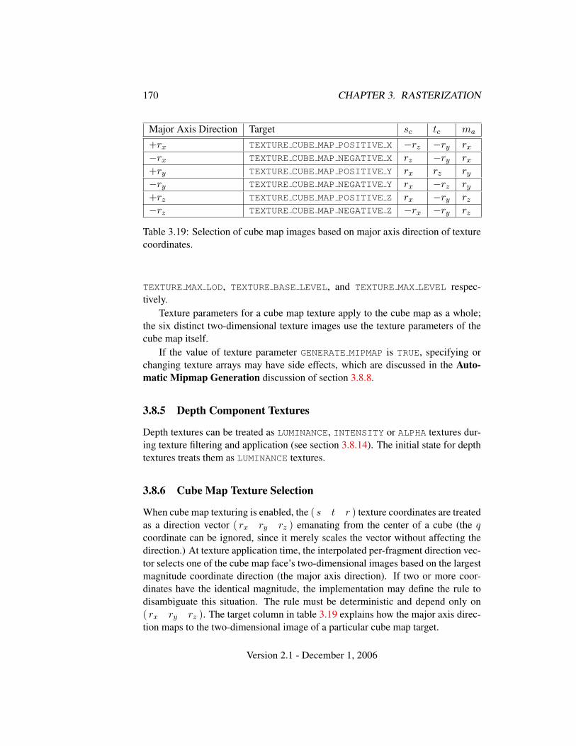
170 CHAPTER 3. RASTERIZATION
Major Axis Direction Target sc tc ma
+rx TEXTURE CUBE MAP POSITIVE X −rz −ry rx
−rx TEXTURE CUBE MAP NEGATIVE X rz −ry rx
+ry TEXTURE CUBE MAP POSITIVE Y rx rz ry
−ry TEXTURE CUBE MAP NEGATIVE Y rx −rz ry
+rz TEXTURE CUBE MAP POSITIVE Z rx −ry rz
−rz TEXTURE CUBE MAP NEGATIVE Z −rx −ry rz
Table 3.19: Selection of cube map images based on major axis direction of texturecoordinates.
TEXTURE MAX LOD, TEXTURE BASE LEVEL, and TEXTURE MAX LEVEL respec-tively.
Texture parameters for a cube map texture apply to the cube map as a whole;the six distinct two-dimensional texture images use the texture parameters of thecube map itself.
If the value of texture parameter GENERATE MIPMAP is TRUE, specifying orchanging texture arrays may have side effects, which are discussed in the Auto-matic Mipmap Generation discussion of section 3.8.8.
3.8.5 Depth Component Textures
Depth textures can be treated as LUMINANCE, INTENSITY or ALPHA textures dur-ing texture filtering and application (see section 3.8.14). The initial state for depthtextures treats them as LUMINANCE textures.
3.8.6 Cube Map Texture Selection
When cube map texturing is enabled, the ( s t r ) texture coordinates are treatedas a direction vector ( rx ry rz ) emanating from the center of a cube (the qcoordinate can be ignored, since it merely scales the vector without affecting thedirection.) At texture application time, the interpolated per-fragment direction vec-tor selects one of the cube map face’s two-dimensional images based on the largestmagnitude coordinate direction (the major axis direction). If two or more coor-dinates have the identical magnitude, the implementation may define the rule todisambiguate this situation. The rule must be deterministic and depend only on( rx ry rz ). The target column in table 3.19 explains how the major axis direc-tion maps to the two-dimensional image of a particular cube map target.
Version 2.1 - December 1, 2006
3.8. TEXTURING 171
Using the sc, tc, and ma determined by the major axis direction as specified intable 3.19, an updated ( s t ) is calculated as follows:
s =12
(sc
|ma|+ 1
)
t =12
(tc|ma|
+ 1)
This new ( s t ) is used to find a texture value in the determined face’s two-dimensional texture image using the rules given in sections 3.8.7 through 3.8.9.
3.8.7 Texture Wrap Modes
Wrap modes defined by the values of TEXTURE WRAP S, TEXTURE WRAP T, orTEXTURE WRAP R respectively affect the interpretation of s, t, and r texture co-ordinates. The effect of each mode is described below.
Wrap Mode REPEAT
Wrap mode REPEAT ignores the integer part of texture coordinates, using only thefractional part. (For a number f , the fractional part is f − bfc, regardless of thesign of f ; recall that the bc function truncates towards −∞.)
REPEAT is the default behavior for all texture coordinates.
Wrap Mode CLAMP
Wrap mode CLAMP clamps texture coordinates to range [0, 1].
Wrap Mode CLAMP TO EDGE
Wrap mode CLAMP TO EDGE clamps texture coordinates at all mipmap levels suchthat the texture filter never samples a border texel. The color returned when clamp-ing is derived only from texels at the edge of the texture image.
Texture coordinates are clamped to the range [min,max]. The minimum valueis defined as
min =1
2N
where N is the size of the one-, two-, or three-dimensional texture image in thedirection of clamping. The maximum value is defined as
Version 2.1 - December 1, 2006
172 CHAPTER 3. RASTERIZATION
max = 1−min
so that clamping is always symmetric about the [0, 1] mapped range of a texturecoordinate.
Wrap Mode CLAMP TO BORDER
Wrap mode CLAMP TO BORDER clamps texture coordinates at all mipmaps suchthat the texture filter always samples border texels for fragments whose correspond-ing texture coordinate is sufficiently far outside the range [0, 1]. The color returnedwhen clamping is derived only from the border texels of the texture image, or fromthe constant border color if the texture image does not have a border.
Texture coordinates are clamped to the range [min,max]. The minimum valueis defined as
min =−12N
where N is the size (not including borders) of the one-, two-, or three-dimensionaltexture image in the direction of clamping. The maximum value is defined as
max = 1−min
so that clamping is always symmetric about the [0, 1] mapped range of a texturecoordinate.
Wrap Mode MIRRORED REPEAT
Wrap mode MIRRORED REPEAT first mirrors the texture coordinate, where mirror-ing a value f computes
mirror(f) =
{f − bfc, bfc is even1− (f − bfc), bfc is odd
The mirrored coordinate is then clamped as described above for wrap modeCLAMP TO EDGE.
3.8.8 Texture Minification
Applying a texture to a primitive implies a mapping from texture image space toframebuffer image space. In general, this mapping involves a reconstruction ofthe sampled texture image, followed by a homogeneous warping implied by the
Version 2.1 - December 1, 2006
3.8. TEXTURING 173
mapping to framebuffer space, then a filtering, followed finally by a resamplingof the filtered, warped, reconstructed image before applying it to a fragment. Inthe GL this mapping is approximated by one of two simple filtering schemes. Oneof these schemes is selected based on whether the mapping from texture space toframebuffer space is deemed to magnify or minify the texture image.
Scale Factor and Level of Detail
The choice is governed by a scale factor ρ(x, y) and the level-of-detail parameterλ(x, y), defined as
λbase(x, y) = log2[ρ(x, y)] (3.18)
λ′(x, y) = λbase(x, y) + clamp(biastexobj + biastexunit + biasshader) (3.19)
λ =
lodmax, λ′ > lodmax
λ′, lodmin ≤ λ′ ≤ lodmax
lodmin, λ′ < lodmin
undefined, lodmin > lodmax
(3.20)
biastexobj is the value of TEXTURE LOD BIAS for the bound texture object (as de-scribed in section 3.8.4). biastexunit is the value of TEXTURE LOD BIAS for thecurrent texture unit (as described in section 3.8.13). biasshader is the value ofthe optional bias parameter in the texture lookup functions available to fragmentshaders. If the texture access is performed in a fragment shader without a providedbias, or outside a fragment shader, then biasshader is zero. The sum of these valuesis clamped to the range [−biasmax, biasmax] where biasmax is the value of theimplementation defined constant MAX TEXTURE LOD BIAS.
If λ(x, y) is less than or equal to the constant c (described below in sec-tion 3.8.9) the texture is said to be magnified; if it is greater, the texture is minified.
The initial values of lodmin and lodmax are chosen so as to never clamp thenormal range of λ. They may be respecified for a specific texture by calling Tex-Parameter[if] with pname set to TEXTURE MIN LOD or TEXTURE MAX LOD re-spectively.
Let s(x, y) be the function that associates an s texture coordinate with eachset of window coordinates (x, y) that lie within a primitive; define t(x, y) andr(x, y) analogously. Let u(x, y) = wt × s(x, y), v(x, y) = ht × t(x, y), andw(x, y) = dt×r(x, y), where wt, ht, and dt are as defined by equations 3.15, 3.16,and 3.17 with ws, hs, and ds equal to the width, height, and depth of the image
Version 2.1 - December 1, 2006
174 CHAPTER 3. RASTERIZATION
array whose level is levelbase. For a one-dimensional texture, define v(x, y) ≡0 and w(x, y) ≡ 0; for a two-dimensional texture, define w(x, y) ≡ 0. For apolygon, ρ is given at a fragment with window coordinates (x, y) by
ρ = max
√(
∂u
∂x
)2
+(
∂v
∂x
)2
+(
∂w
∂x
)2
,
√(∂u
∂y
)2
+(
∂v
∂y
)2
+(
∂w
∂y
)2
(3.21)where ∂u/∂x indicates the derivative of u with respect to window x, and similarlyfor the other derivatives.
For a line, the formula is
ρ =
√(∂u
∂x∆x +
∂u
∂y∆y
)2
+(
∂v
∂x∆x +
∂v
∂y∆y
)2
+(
∂w
∂x∆x +
∂w
∂y∆y
)2/l,
(3.22)where ∆x = x2 − x1 and ∆y = y2 − y1 with (x1, y1) and (x2, y2) being thesegment’s window coordinate endpoints and l =
√∆x2 + ∆y2. For a point, pixel
rectangle, or bitmap, ρ ≡ 1.While it is generally agreed that equations 3.21 and 3.22 give the best results
when texturing, they are often impractical to implement. Therefore, an imple-mentation may approximate the ideal ρ with a function f(x, y) subject to theseconditions:
1. f(x, y) is continuous and monotonically increasing in each of |∂u/∂x|,|∂u/∂y|, |∂v/∂x|, |∂v/∂y|, |∂w/∂x|, and |∂w/∂y|
2. Letmu = max
{∣∣∣∣∂u
∂x
∣∣∣∣ , ∣∣∣∣∂u
∂y
∣∣∣∣}
mv = max{∣∣∣∣∂v
∂x
∣∣∣∣ , ∣∣∣∣∂v
∂y
∣∣∣∣}
mw = max{∣∣∣∣∂w
∂x
∣∣∣∣ , ∣∣∣∣∂w
∂y
∣∣∣∣} .
Then max{mu,mv,mw} ≤ f(x, y) ≤ mu + mv + mw.
When λ indicates minification, the value assigned to TEXTURE MIN FILTER
is used to determine how the texture value for a fragment is selected. When
Version 2.1 - December 1, 2006
3.8. TEXTURING 175
TEXTURE MIN FILTER is NEAREST, the texel in the image array of level levelbase
that is nearest (in Manhattan distance) to that specified by (s, t, r) is obtained. Thismeans the texel at location (i, j, k) becomes the texture value, with i given by
i =
{buc, s < 1wt − 1, s = 1
(3.23)
(Recall that if TEXTURE WRAP S is REPEAT, then 0 ≤ s < 1.) Similarly, j is foundas
j =
{bvc, t < 1ht − 1, t = 1
(3.24)
and k is found as
k =
{bwc, r < 1dt − 1, r = 1
(3.25)
For a one-dimensional texture, j and k are irrelevant; the texel at location i be-comes the texture value. For a two-dimensional texture, k is irrelevant; the texel atlocation (i, j) becomes the texture value.
When TEXTURE MIN FILTER is LINEAR, a 2 × 2 × 2 cube of texels in theimage array of level levelbase is selected. This cube is obtained by first wrappingtexture coordinates as described in section 3.8.7, then computing
i0 =
{bu− 1/2c mod wt, TEXTURE WRAP S is REPEATbu− 1/2c, otherwise
j0 =
{bv − 1/2c mod ht, TEXTURE WRAP T is REPEATbv − 1/2c, otherwise
and
k0 =
{bw − 1/2c mod dt, TEXTURE WRAP R is REPEATbw − 1/2c, otherwise
Then
i1 =
{(i0 + 1) mod wt, TEXTURE WRAP S is REPEATi0 + 1, otherwise
j1 =
{(j0 + 1) mod ht, TEXTURE WRAP T is REPEATj0 + 1, otherwise
Version 2.1 - December 1, 2006
176 CHAPTER 3. RASTERIZATION
and
k1 =
{(k0 + 1) mod dt, TEXTURE WRAP R is REPEATk0 + 1, otherwise
Letα = frac(u− 1/2)
β = frac(v − 1/2)
γ = frac(w − 1/2)
where frac(x) denotes the fractional part of x.For a three-dimensional texture, the texture value τ is found as
τ = (1− α)(1− β)(1− γ)τi0j0k0 + α(1− β)(1− γ)τi1j0k0
+ (1− α)β(1− γ)τi0j1k0 + αβ(1− γ)τi1j1k0
+ (1− α)(1− β)γτi0j0k1 + α(1− β)γτi1j0k1
+ (1− α)βγτi0j1k1 + αβγτi1j1k1
where τijk is the texel at location (i, j, k) in the three-dimensional texture image.For a two-dimensional texture,
τ = (1− α)(1− β)τi0j0 + α(1− β)τi1j0 + (1− α)βτi0j1 + αβτi1j1 (3.26)
where τij is the texel at location (i, j) in the two-dimensional texture image.And for a one-dimensional texture,
τ = (1− α)τi0 + ατi1
where τi is the texel at location i in the one-dimensional texture.If any of the selected τijk, τij , or τi in the above equations refer to a border
texel with i < −bs, j < −bs, k < −bs, i ≥ ws − bs, j ≥ hs − bs, or j ≥ ds − bs,then the border values defined by TEXTURE BORDER COLOR are used instead of theunspecified value or values. If the texture contains color components, the values ofTEXTURE BORDER COLOR are interpreted as an RGBA color to match the texture’sinternal format in a manner consistent with table 3.15. If the texture contains depthcomponents, the first component of TEXTURE BORDER COLOR is interpreted as adepth value.
Version 2.1 - December 1, 2006
3.8. TEXTURING 177
Mipmapping
TEXTURE MIN FILTER values NEAREST MIPMAP NEAREST,NEAREST MIPMAP LINEAR, LINEAR MIPMAP NEAREST,and LINEAR MIPMAP LINEAR each require the use of a mipmap. A mipmap isan ordered set of arrays representing the same image; each array has a resolutionlower than the previous one. If the image array of level levelbase, excluding itsborder, has dimensions wb × hb × db, then there are blog2(max(wb, hb, db))c + 1image arrays in the mipmap. Numbering the levels such that level levelbase is the0th level, the ith array has dimensions
max(1, bwb
2ic)×max(1, bhb
2ic)×max(1, bdb
2ic)
until the last array is reached with dimension 1× 1× 1.Each array in a mipmap is defined using TexImage3D, TexImage2D, Copy-
TexImage2D, TexImage1D, or CopyTexImage1D; the array being set is indicatedwith the level-of-detail argument level. Level-of-detail numbers proceed fromlevelbase for the original texture array through p = blog2(max(wb, hb, db))c +levelbase with each unit increase indicating an array of half the dimensions of theprevious one (rounded down to the next integer if fractional) as already described.All arrays from levelbase through q = min{p, levelmax} must be defined, as dis-cussed in section 3.8.10.
The values of levelbase and levelmax may be respecified for a specific tex-ture by calling TexParameter[if] with pname set to TEXTURE BASE LEVEL orTEXTURE MAX LEVEL respectively.
The error INVALID VALUE is generated if either value is negative.The mipmap is used in conjunction with the level of detail to approximate the
application of an appropriately filtered texture to a fragment. Let c be the valueof λ at which the transition from minification to magnification occurs (since thisdiscussion pertains to minification, we are concerned only with values of λ whereλ > c).
For mipmap filters NEAREST MIPMAP NEAREST andLINEAR MIPMAP NEAREST, the dth mipmap array is selected, where
d =
levelbase, λ ≤ 1
2dlevelbase + λ + 1
2e − 1, λ > 12 , levelbase + λ ≤ q + 1
2q, λ > 1
2 , levelbase + λ > q + 12
(3.27)
The rules for NEAREST or LINEAR filtering are then applied to the selectedarray.
Version 2.1 - December 1, 2006
178 CHAPTER 3. RASTERIZATION
For mipmap filters NEAREST MIPMAP LINEAR and LINEAR MIPMAP LINEAR,the level d1 and d2 mipmap arrays are selected, where
d1 =
{q, levelbase + λ ≥ qblevelbase + λc, otherwise
(3.28)
d2 =
{q, levelbase + λ ≥ qd1 + 1, otherwise
(3.29)
The rules for NEAREST or LINEAR filtering are then applied to each of theselected arrays, yielding two corresponding texture values τ1 and τ2. The finaltexture value is then found as
τ = [1− frac(λ)]τ1 + frac(λ)τ2.
Automatic Mipmap Generation
If the value of texture parameter GENERATE MIPMAP is TRUE, making any changeto the interior or border texels of the levelbase array of a mipmap will also computea complete set of mipmap arrays (as defined in section 3.8.10) derived from themodified levelbase array. Array levels levelbase + 1 through p are replaced withthe derived arrays, regardless of their previous contents. All other mipmap arrays,including the levelbase array, are left unchanged by this computation.
The internal formats and border widths of the derived mipmap arrays all matchthose of the levelbase array, and the dimensions of the derived arrays follow therequirements described in section 3.8.10.
The contents of the derived arrays are computed by repeated, filtered reductionof the levelbase array. No particular filter algorithm is required, though a box filteris recommended as the default filter. In some implementations, filter quality maybe affected by hints (section 5.6).
Automatic mipmap generation is available only for non-proxy texture imagetargets.
3.8.9 Texture Magnification
When λ indicates magnification, the value assigned to TEXTURE MAG FILTER
determines how the texture value is obtained. There are two possible valuesfor TEXTURE MAG FILTER: NEAREST and LINEAR. NEAREST behaves exactly asNEAREST for TEXTURE MIN FILTER (equations 3.23, 3.24, and 3.25 are used);LINEAR behaves exactly as LINEAR for TEXTURE MIN FILTER (equation 3.26 isused). The level-of-detail levelbase texture array is always used for magnification.
Version 2.1 - December 1, 2006
3.8. TEXTURING 179
Finally, there is the choice of c, the minification vs. magnification switch-over point. If the magnification filter is given by LINEAR and the minificationfilter is given by NEAREST MIPMAP NEAREST or NEAREST MIPMAP LINEAR, thenc = 0.5. This is done to ensure that a minified texture does not appear “sharper”than a magnified texture. Otherwise c = 0.
3.8.10 Texture Completeness
A texture is said to be complete if all the image arrays and texture parametersrequired to utilize the texture for texture application are consistently defined. Thedefinition of completeness varies depending on the texture dimensionality.
For one-, two-, or three-dimensional textures, a texture is complete if the fol-lowing conditions all hold true:
• The set of mipmap arrays levelbase through q (where q is defined in theMipmapping discussion of section 3.8.8) were each specified with the sameinternal format.
• The border widths of each array are the same.
• The dimensions of the arrays follow the sequence described in the Mipmap-ping discussion of section 3.8.8.
• levelbase ≤ levelmax
• Each dimension of the levelbase array is positive.
Array levels k where k < levelbase or k > q are insignificant to the definition ofcompleteness.
For cube map textures, a texture is cube complete if the following conditionsall hold true:
• The levelbase arrays of each of the six texture images making up the cubemap have identical, positive, and square dimensions.
• The levelbase arrays were each specified with the same internal format.
• The levelbase arrays each have the same border width.
Finally, a cube map texture is mipmap cube complete if, in addition to beingcube complete, each of the six texture images considered individually is complete.
Version 2.1 - December 1, 2006
180 CHAPTER 3. RASTERIZATION
Effects of Completeness on Texture Application
If one-, two-, or three-dimensional texturing (but not cube map textur-ing) is enabled for a texture unit at the time a primitive is rasterized, ifTEXTURE MIN FILTER is one that requires a mipmap, and if the texture imagebound to the enabled texture target is not complete, then it is as if texture mappingwere disabled for that texture unit.
If cube map texturing is enabled for a texture unit at the time a primitiveis rasterized, and if the bound cube map texture is not cube complete, then itis as if texture mapping were disabled for that texture unit. Additionally, ifTEXTURE MIN FILTER is one that requires a mipmap, and if the texture is notmipmap cube complete, then it is as if texture mapping were disabled for that tex-ture unit.
Effects of Completeness on Texture Image Specification
An implementation may allow a texture image array of level 1 or greater to be cre-ated only if a mipmap complete set of image arrays consistent with the requestedarray can be supported. A mipmap complete set of arrays is equivalent to a com-plete set of arrays where levelbase = 0 and levelmax = 1000, and where, excludingborders, the dimensions of the image array being created are understood to be halfthe corresponding dimensions of the next lower numbered array (rounded down tothe next integer if fractional).
3.8.11 Texture State and Proxy State
The state necessary for texture can be divided into two categories. First, there arethe nine sets of mipmap arrays (one each for the one-, two-, and three-dimensionaltexture targets and six for the cube map texture targets) and their number. Each ar-ray has associated with it a width, height (two- and three-dimensional and cubemap only), and depth (three-dimensional only), a border width, an integer de-scribing the internal format of the image, six integer values describing the res-olutions of each of the red, green, blue, alpha, luminance, and intensity com-ponents of the image, a boolean describing whether the image is compressed ornot, and an integer size of a compressed image. Each initial texture array isnull (zero width, height, and depth, zero border width, internal format 1, withthe compressed flag set to FALSE, a zero compressed size, and zero-sized com-ponents). Next, there are the two sets of texture properties; each consists ofthe selected minification and magnification filters, the wrap modes for s, t (two-and three-dimensional and cube map only), and r (three-dimensional only), theTEXTURE BORDER COLOR, two integers describing the minimum and maximum
Version 2.1 - December 1, 2006
3.8. TEXTURING 181
level of detail, two integers describing the base and maximum mipmap array,a boolean flag indicating whether the texture is resident, a boolean indicatingwhether automatic mipmap generation should be performed, three integers de-scribing the depth texture mode, compare mode, and compare function, and thepriority associated with each set of properties. The value of the resident flag isdetermined by the GL and may change as a result of other GL operations. The flagmay only be queried, not set, by applications (see section 3.8.12). In the initialstate, the value assigned to TEXTURE MIN FILTER is NEAREST MIPMAP LINEAR,and the value for TEXTURE MAG FILTER is LINEAR. s, t, and r wrap modesare all set to REPEAT. The values of TEXTURE MIN LOD and TEXTURE MAX LOD
are -1000 and 1000 respectively. The values of TEXTURE BASE LEVEL andTEXTURE MAX LEVEL are 0 and 1000 respectively. TEXTURE PRIORITY is 1.0,and TEXTURE BORDER COLOR is (0,0,0,0). The value of GENERATE MIPMAP
is false. The values of DEPTH TEXTURE MODE, TEXTURE COMPARE MODE, andTEXTURE COMPARE FUNC are LUMINANCE, NONE, and LEQUAL respectively. Theinitial value of TEXTURE RESIDENT is determined by the GL.
In addition to the one-, two-, and three-dimensional and the six cube map setsof image arrays, the partially instantiated one-, two-, and three-dimensional andone cube map set of proxy image arrays are maintained. Each proxy array includeswidth, height (two- and three-dimensional arrays only), depth (three-dimensionalarrays only), border width, and internal format state values, as well as state forthe red, green, blue, alpha, luminance, and intensity component resolutions. Proxyarrays do not include image data, nor do they include texture properties. WhenTexImage3D is executed with target specified as PROXY TEXTURE 3D, the three-dimensional proxy state values of the specified level-of-detail are recomputed andupdated. If the image array would not be supported by TexImage3D called withtarget set to TEXTURE 3D, no error is generated, but the proxy width, height, depth,border width, and component resolutions are set to zero. If the image array wouldbe supported by such a call to TexImage3D, the proxy state values are set exactlyas though the actual image array were being specified. No pixel data are transferredor processed in either case.
One- and two-dimensional proxy arrays are operated on in the same way whenTexImage1D is executed with target specified as PROXY TEXTURE 1D, or TexIm-age2D is executed with target specified as PROXY TEXTURE 2D.
The cube map proxy arrays are operated on in the same manner when TexIm-age2D is executed with the target field specified as PROXY TEXTURE CUBE MAP,with the addition that determining that a given cube map texture is supported withPROXY TEXTURE CUBE MAP indicates that all six of the cube map 2D images aresupported. Likewise, if the specified PROXY TEXTURE CUBE MAP is not supported,none of the six cube map 2D images are supported.
Version 2.1 - December 1, 2006
182 CHAPTER 3. RASTERIZATION
There is no image associated with any of the proxy textures. There-fore PROXY TEXTURE 1D, PROXY TEXTURE 2D, and PROXY TEXTURE 3D, andPROXY TEXTURE CUBE MAP cannot be used as textures, and their images mustnever be queried using GetTexImage. The error INVALID ENUM is generated ifthis is attempted. Likewise, there is no non level-related state associated with aproxy texture, and GetTexParameteriv or GetTexParameterfv may not be calledwith a proxy texture target. The error INVALID ENUM is generated if this is at-tempted.
3.8.12 Texture Objects
In addition to the default textures TEXTURE 1D, TEXTURE 2D, TEXTURE 3D, andTEXTURE CUBE MAP, named one-, two-, and three-dimensional and cube map tex-ture objects can be created and operated upon. The name space for texture objectsis the unsigned integers, with zero reserved by the GL.
A texture object is created by binding an unused name to TEXTURE 1D,TEXTURE 2D, TEXTURE 3D, or TEXTURE CUBE MAP. The binding is effected bycalling
void BindTexture( enum target, uint texture );
with target set to the desired texture target and texture set to the unused name.The resulting texture object is a new state vector, comprising all the state valueslisted in section 3.8.11, set to the same initial values. If the new texture object isbound to TEXTURE 1D, TEXTURE 2D, TEXTURE 3D, or TEXTURE CUBE MAP, it isand remains a one-, two-, three-dimensional, or cube map texture respectively untilit is deleted.
BindTexture may also be used to bind an existing texture object to ei-ther TEXTURE 1D, TEXTURE 2D, TEXTURE 3D, or TEXTURE CUBE MAP. The errorINVALID OPERATION is generated if an attempt is made to bind a texture objectof a different target than the specified target. If the bind is successful no change ismade to the state of the bound texture object, and any previous binding to target isbroken.
While a texture object is bound, GL operations on the target to which it isbound affect the bound object, and queries of the target to which it is bound returnstate from the bound object. If texture mapping of the dimensionality of the targetto which a texture object is bound is enabled, the state of the bound texture objectdirects the texturing operation.
In the initial state, TEXTURE 1D, TEXTURE 2D, TEXTURE 3D,and TEXTURE CUBE MAP have one-, two-, three-dimensional, and cube map tex-ture state vectors respectively associated with them. In order that access to these
Version 2.1 - December 1, 2006
3.8. TEXTURING 183
initial textures not be lost, they are treated as texture objects all of whose namesare 0. The initial one-, two-, three-dimensional, and cube map texture is thereforeoperated upon, queried, and applied as TEXTURE 1D, TEXTURE 2D, TEXTURE 3D,or TEXTURE CUBE MAP respectively while 0 is bound to the corresponding targets.
Texture objects are deleted by calling
void DeleteTextures( sizei n, uint *textures );
textures contains n names of texture objects to be deleted. After a texture objectis deleted, it has no contents or dimensionality, and its name is again unused. Ifa texture that is currently bound to one of the targets TEXTURE 1D, TEXTURE 2D,TEXTURE 3D, or TEXTURE CUBE MAP is deleted, it is as though BindTexture hadbeen executed with the same target and texture zero. Unused names in textures aresilently ignored, as is the value zero.
The command
void GenTextures( sizei n, uint *textures );
returns n previously unused texture object names in textures. These names aremarked as used, for the purposes of GenTextures only, but they acquire texturestate and a dimensionality only when they are first bound, just as if they wereunused.
An implementation may choose to establish a working set of texture objects onwhich binding operations are performed with higher performance. A texture objectthat is currently part of the working set is said to be resident. The command
boolean AreTexturesResident( sizei n, uint *textures,boolean *residences );
returns TRUE if all of the n texture objects named in textures are resident, or if theimplementation does not distinguish a working set. If at least one of the textureobjects named in textures is not resident, then FALSE is returned, and the residenceof each texture object is returned in residences. Otherwise the contents of resi-dences are not changed. If any of the names in textures are unused or are zero,FALSE is returned, the error INVALID VALUE is generated, and the contents of res-idences are indeterminate. The residence status of a single bound texture objectcan also be queried by calling GetTexParameteriv or GetTexParameterfv withtarget set to the target to which the texture object is bound, and pname set toTEXTURE RESIDENT.
AreTexturesResident indicates only whether a texture object is currently resi-dent, not whether it could not be made resident. An implementation may choose to
Version 2.1 - December 1, 2006
184 CHAPTER 3. RASTERIZATION
make a texture object resident only on first use, for example. The client may guidethe GL implementation in determining which texture objects should be resident byspecifying a priority for each texture object. The command
void PrioritizeTextures( sizei n, uint *textures,clampf *priorities );
sets the priorities of the n texture objects named in textures to the values in priori-ties. Each priority value is clamped to the range [0,1] before it is assigned. Zero in-dicates the lowest priority, with the least likelihood of being resident. One indicatesthe highest priority, with the greatest likelihood of being resident. The priority of asingle bound texture object may also be changed by calling TexParameteri, Tex-Parameterf, TexParameteriv, or TexParameterfv with target set to the target towhich the texture object is bound, pname set to TEXTURE PRIORITY, and paramor params specifying the new priority value (which is clamped to the range [0,1]before being assigned). PrioritizeTextures silently ignores attempts to prioritizeunused texture object names or zero (default textures).
The texture object name space, including the initial one-, two-, and three-dimensional texture objects, is shared among all texture units. A texture objectmay be bound to more than one texture unit simultaneously. After a texture objectis bound, any GL operations on that target object affect any other texture units towhich the same texture object is bound.
Texture binding is affected by the setting of the state ACTIVE TEXTURE.If a texture object is deleted, it as if all texture units which are bound to that
texture object are rebound to texture object zero.
3.8.13 Texture Environments and Texture Functions
The command
void TexEnv{if}( enum target, enum pname, T param );void TexEnv{if}v( enum target, enum pname, T params );
sets parameters of the texture environment that specifies how texture values areinterpreted when texturing a fragment, or sets per-texture-unit filtering parameters.
target must be one of POINT SPRITE, TEXTURE ENV orTEXTURE FILTER CONTROL. pname is a symbolic constant indicating theparameter to be set. In the first form of the command, param is a value to which toset a single-valued parameter; in the second form, params is a pointer to an arrayof parameters: either a single symbolic constant or a value or group of values towhich the parameter should be set.
Version 2.1 - December 1, 2006
3.8. TEXTURING 185
When target is POINT SPRITE, point sprite rasterization behavior is affectedas described in section 3.3.
When target is TEXTURE FILTER CONTROL, pname must beTEXTURE LOD BIAS. In this case the parameter is a single signed floatingpoint value, biastexunit, that biases the level of detail parameter λ as described insection 3.8.8.
When target is TEXTURE ENV, the possible environment parameters areTEXTURE ENV MODE, TEXTURE ENV COLOR, COMBINE RGB, COMBINE ALPHA,RGB SCALE, ALPHA SCALE, SRCn RGB, SRCn ALPHA, OPERANDn RGB, andOPERANDn ALPHA, where n = 0, 1, or 2. TEXTURE ENV MODE may be set to one ofREPLACE, MODULATE, DECAL, BLEND, ADD, or COMBINE. TEXTURE ENV COLOR isset to an RGBA color by providing four single-precision floating-point values inthe range [0, 1] (values outside this range are clamped to it). If integers are providedfor TEXTURE ENV COLOR, then they are converted to floating-point as specified intable 2.9 for signed integers.
The value of TEXTURE ENV MODE specifies a texture function. The result ofthis function depends on the fragment and the texture array value. The preciseform of the function depends on the base internal formats of the texture arrays thatwere last specified.
Cf and Af3 are the primary color components of the incoming fragment; Cs
and As are the components of the texture source color, derived from the filteredtexture values Rt, Gt, Bt, At, Lt, and It as shown in table 3.20; Cc and Ac arethe components of the texture environment color; Cp and Ap are the componentsresulting from the previous texture environment (for texture environment 0, Cp andAp are identical to Cf and Af , respectively); and Cv and Av are the primary colorcomponents computed by the texture function.
All of these color values are in the range [0, 1]. The texture functions are spec-ified in tables 3.21, 3.22, and 3.23.
If the value of TEXTURE ENV MODE is COMBINE, the form of the texture func-tion depends on the values of COMBINE RGB and COMBINE ALPHA, according totable 3.23. The RGB and ALPHA results of the texture function are then multi-plied by the values of RGB SCALE and ALPHA SCALE, respectively. The results areclamped to [0, 1].
The arguments Arg0, Arg1, and Arg2 are determined by the values ofSRCn RGB, SRCn ALPHA, OPERANDn RGB and OPERANDn ALPHA, where n = 0,1, or 2, as shown in tables 3.24 and 3.25. Cs
n and Asn denote the texture source
3In the remainder of section 3.8.13, the notation Cx is used to denote each of the three componentsRx, Gx, and Bx of a color specified by x. Operations on Cx are performed independently for eachcolor component. The A component of colors is usually operated on in a different fashion, and istherefore denoted separately by Ax.
Version 2.1 - December 1, 2006
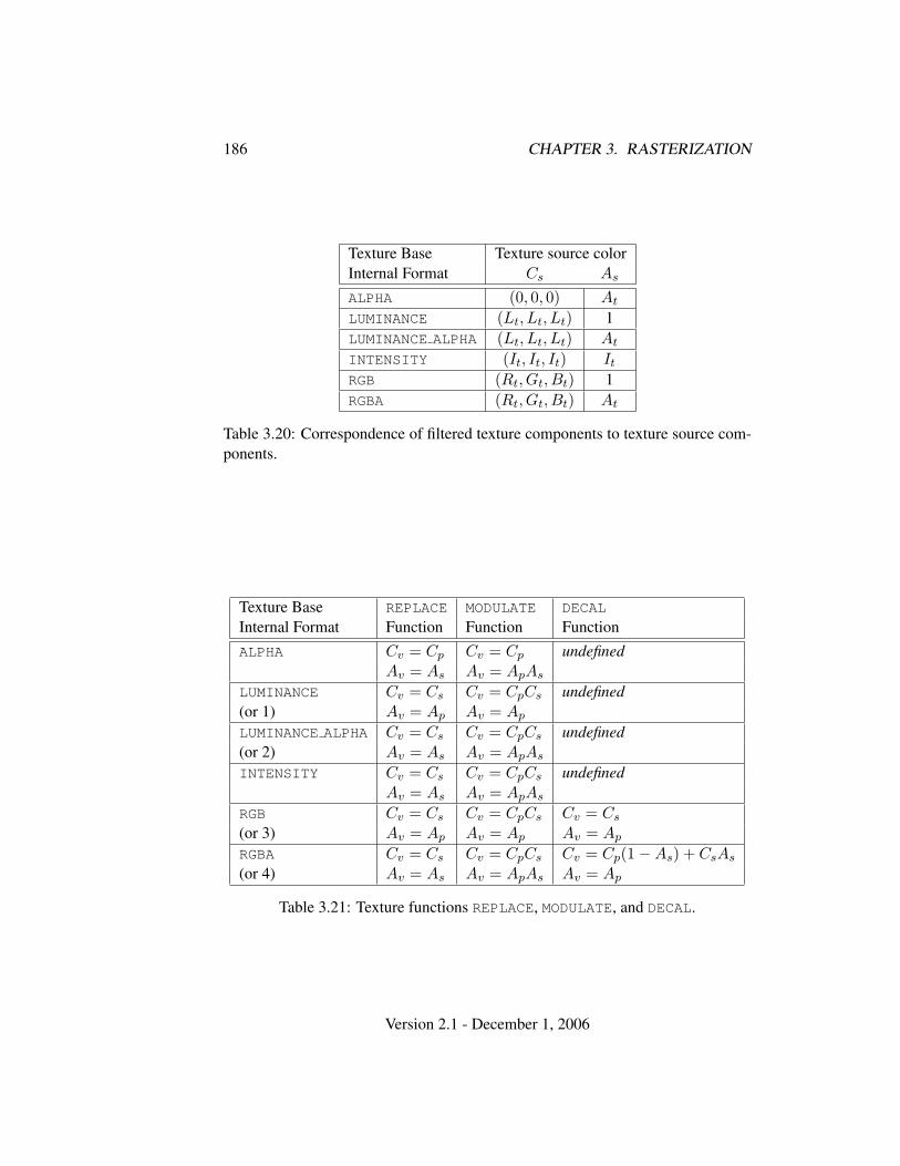
186 CHAPTER 3. RASTERIZATION
Texture Base Texture source colorInternal Format Cs As
ALPHA (0, 0, 0) At
LUMINANCE (Lt, Lt, Lt) 1LUMINANCE ALPHA (Lt, Lt, Lt) At
INTENSITY (It, It, It) It
RGB (Rt, Gt, Bt) 1RGBA (Rt, Gt, Bt) At
Table 3.20: Correspondence of filtered texture components to texture source com-ponents.
Texture Base REPLACE MODULATE DECAL
Internal Format Function Function FunctionALPHA Cv = Cp Cv = Cp undefined
Av = As Av = ApAs
LUMINANCE Cv = Cs Cv = CpCs undefined(or 1) Av = Ap Av = Ap
LUMINANCE ALPHA Cv = Cs Cv = CpCs undefined(or 2) Av = As Av = ApAs
INTENSITY Cv = Cs Cv = CpCs undefinedAv = As Av = ApAs
RGB Cv = Cs Cv = CpCs Cv = Cs
(or 3) Av = Ap Av = Ap Av = Ap
RGBA Cv = Cs Cv = CpCs Cv = Cp(1−As) + CsAs
(or 4) Av = As Av = ApAs Av = Ap
Table 3.21: Texture functions REPLACE, MODULATE, and DECAL.
Version 2.1 - December 1, 2006
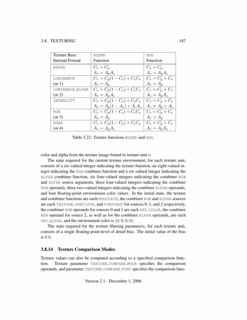
3.8. TEXTURING 187
Texture Base BLEND ADD
Internal Format Function FunctionALPHA Cv = Cp Cv = Cp
Av = ApAs Av = ApAs
LUMINANCE Cv = Cp(1− Cs) + CcCs Cv = Cp + Cs
(or 1) Av = Ap Av = Ap
LUMINANCE ALPHA Cv = Cp(1− Cs) + CcCs Cv = Cp + Cs
(or 2) Av = ApAs Av = ApAs
INTENSITY Cv = Cp(1− Cs) + CcCs Cv = Cp + Cs
Av = Ap(1−As) + AcAs Av = Ap + As
RGB Cv = Cp(1− Cs) + CcCs Cv = Cp + Cs
(or 3) Av = Ap Av = Ap
RGBA Cv = Cp(1− Cs) + CcCs Cv = Cp + Cs
(or 4) Av = ApAs Av = ApAs
Table 3.22: Texture functions BLEND and ADD.
color and alpha from the texture image bound to texture unit n
The state required for the current texture environment, for each texture unit,consists of a six-valued integer indicating the texture function, an eight-valued in-teger indicating the RGB combiner function and a six-valued integer indicating theALPHA combiner function, six four-valued integers indicating the combiner RGBand ALPHA source arguments, three four-valued integers indicating the combinerRGB operands, three two-valued integers indicating the combiner ALPHA operands,and four floating-point environment color values. In the initial state, the textureand combiner functions are each MODULATE, the combiner RGB and ALPHA sourcesare each TEXTURE, PREVIOUS, and CONSTANT for sources 0, 1, and 2 respectively,the combiner RGB operands for sources 0 and 1 are each SRC COLOR, the combinerRGB operand for source 2, as well as for the combiner ALPHA operands, are eachSRC ALPHA, and the environment color is (0, 0, 0, 0).
The state required for the texture filtering parameters, for each texture unit,consists of a single floating-point level of detail bias. The initial value of the biasis 0.0.
3.8.14 Texture Comparison Modes
Texture values can also be computed according to a specified comparison func-tion. Texture parameter TEXTURE COMPARE MODE specifies the comparisonoperands, and parameter TEXTURE COMPARE FUNC specifies the comparison func-
Version 2.1 - December 1, 2006
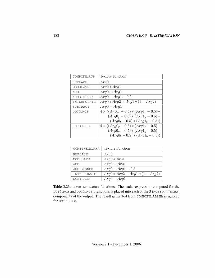
188 CHAPTER 3. RASTERIZATION
COMBINE RGB Texture FunctionREPLACE Arg0MODULATE Arg0 ∗Arg1ADD Arg0 + Arg1ADD SIGNED Arg0 + Arg1− 0.5INTERPOLATE Arg0 ∗Arg2 + Arg1 ∗ (1−Arg2)SUBTRACT Arg0−Arg1DOT3 RGB 4× ((Arg0r − 0.5) ∗ (Arg1r − 0.5)+
(Arg0g − 0.5) ∗ (Arg1g − 0.5)+(Arg0b − 0.5) ∗ (Arg1b − 0.5))
DOT3 RGBA 4× ((Arg0r − 0.5) ∗ (Arg1r − 0.5)+(Arg0g − 0.5) ∗ (Arg1g − 0.5)+(Arg0b − 0.5) ∗ (Arg1b − 0.5))
COMBINE ALPHA Texture FunctionREPLACE Arg0MODULATE Arg0 ∗Arg1ADD Arg0 + Arg1ADD SIGNED Arg0 + Arg1− 0.5INTERPOLATE Arg0 ∗Arg2 + Arg1 ∗ (1−Arg2)SUBTRACT Arg0−Arg1
Table 3.23: COMBINE texture functions. The scalar expression computed for theDOT3 RGB and DOT3 RGBA functions is placed into each of the 3 (RGB) or 4 (RGBA)components of the output. The result generated from COMBINE ALPHA is ignoredfor DOT3 RGBA.
Version 2.1 - December 1, 2006
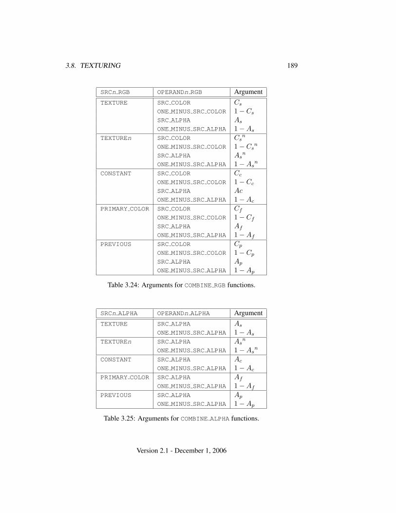
3.8. TEXTURING 189
SRCn RGB OPERANDn RGB ArgumentTEXTURE SRC COLOR Cs
ONE MINUS SRC COLOR 1− Cs
SRC ALPHA As
ONE MINUS SRC ALPHA 1−As
TEXTUREn SRC COLOR Csn
ONE MINUS SRC COLOR 1− Csn
SRC ALPHA Asn
ONE MINUS SRC ALPHA 1−Asn
CONSTANT SRC COLOR Cc
ONE MINUS SRC COLOR 1− Cc
SRC ALPHA AcONE MINUS SRC ALPHA 1−Ac
PRIMARY COLOR SRC COLOR Cf
ONE MINUS SRC COLOR 1− Cf
SRC ALPHA Af
ONE MINUS SRC ALPHA 1−Af
PREVIOUS SRC COLOR Cp
ONE MINUS SRC COLOR 1− Cp
SRC ALPHA Ap
ONE MINUS SRC ALPHA 1−Ap
Table 3.24: Arguments for COMBINE RGB functions.
SRCn ALPHA OPERANDn ALPHA ArgumentTEXTURE SRC ALPHA As
ONE MINUS SRC ALPHA 1−As
TEXTUREn SRC ALPHA Asn
ONE MINUS SRC ALPHA 1−Asn
CONSTANT SRC ALPHA Ac
ONE MINUS SRC ALPHA 1−Ac
PRIMARY COLOR SRC ALPHA Af
ONE MINUS SRC ALPHA 1−Af
PREVIOUS SRC ALPHA Ap
ONE MINUS SRC ALPHA 1−Ap
Table 3.25: Arguments for COMBINE ALPHA functions.
Version 2.1 - December 1, 2006
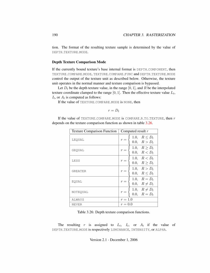
190 CHAPTER 3. RASTERIZATION
tion. The format of the resulting texture sample is determined by the value ofDEPTH TEXTURE MODE.
Depth Texture Comparison Mode
If the currently bound texture’s base internal format is DEPTH COMPONENT, thenTEXTURE COMPARE MODE, TEXTURE COMPARE FUNC and DEPTH TEXTURE MODE
control the output of the texture unit as described below. Otherwise, the textureunit operates in the normal manner and texture comparison is bypassed.
Let Dt be the depth texture value, in the range [0, 1], and R be the interpolatedtexture coordinate clamped to the range [0, 1]. Then the effective texture value Lt,It, or At is computed as follows:
If the value of TEXTURE COMPARE MODE is NONE, then
r = Dt
If the value of TEXTURE COMPARE MODE is COMPARE R TO TEXTURE, then rdepends on the texture comparison function as shown in table 3.26.
Texture Comparison Function Computed result r
LEQUAL r =
{1.0, R ≤ Dt
0.0, R > Dt
GEQUAL r =
{1.0, R ≥ Dt
0.0, R < Dt
LESS r =
{1.0, R < Dt
0.0, R ≥ Dt
GREATER r =
{1.0, R > Dt
0.0, R ≤ Dt
EQUAL r =
{1.0, R = Dt
0.0, R 6= Dt
NOTEQUAL r =
{1.0, R 6= Dt
0.0, R = Dt
ALWAYS r = 1.0NEVER r = 0.0
Table 3.26: Depth texture comparison functions.
The resulting r is assigned to Lt, It, or At if the value ofDEPTH TEXTURE MODE is respectively LUMINANCE, INTENSITY, or ALPHA.
Version 2.1 - December 1, 2006
3.8. TEXTURING 191
If the value of TEXTURE MAG FILTER is not NEAREST, or the value ofTEXTURE MIN FILTER is not NEAREST or NEAREST MIPMAP NEAREST, then rmay be computed by comparing more than one depth texture value to the textureR coordinate. The details of this are implementation-dependent, but r should be avalue in the range [0, 1] which is proportional to the number of comparison passesor failures.
3.8.15 sRGB Texture Color Conversion
If the currently bound texture’s internal format is one of SRGB, SRGB8,SRGB ALPHA, SRGB8 ALPHA8, SLUMINANCE ALPHA, SLUMINANCE8 ALPHA8,SLUMINANCE, SLUMINANCE8, COMPRESSED SRGB, COMPRESSED SRGB ALPHA,COMPRESSED SLUMINANCE, or COMPRESSED SLUMINANCE ALPHA, the red,green, and blue components are converted from an sRGB color space to a lin-ear color space as part of filtering described in sections 3.8.8 and 3.8.9. Any alphacomponent is left unchanged. Ideally, implementations should perform this colorconversion on each sample prior to filtering but implementations are allowed toperform this conversion after filtering (though this post-filtering approach is infe-rior to converting from sRGB prior to filtering).
The conversion from an sRGB encoded component, cs, to a linear component,cl, is as follows.
cl =
cs
12.92 , cs ≤ 0.04045(cs+0.055
1.055
)2.4, cs > 0.04045
(3.30)
Assume cs is the sRGB component in the range [0, 1].
3.8.16 Texture Application
Texturing is enabled or disabled using the generic Enable and Disable com-mands, respectively, with the symbolic constants TEXTURE 1D, TEXTURE 2D,TEXTURE 3D, or TEXTURE CUBE MAP to enable the one-, two, three-dimensional,or cube map texture, respectively. If both two- and one-dimensional textures areenabled, the two-dimensional texture is used. If the three-dimensional and eitherof the two- or one-dimensional textures is enabled, the three-dimensional textureis used. If the cube map texture and any of the three-, two-, or one-dimensionaltextures is enabled, then cube map texturing is used. If all texturing is disabled, arasterized fragment is passed on unaltered to the next stage of the GL (although itstexture coordinates may be discarded). Otherwise, a texture value is found accord-ing to the parameter values of the currently bound texture image of the appropriate
Version 2.1 - December 1, 2006

192 CHAPTER 3. RASTERIZATION
dimensionality using the rules given in sections 3.8.6 through 3.8.9. This texturevalue is used along with the incoming fragment in computing the texture functionindicated by the currently bound texture environment. The result of this functionreplaces the incoming fragment’s primary R, G, B, and A values. These are thecolor values passed to subsequent operations. Other data associated with the in-coming fragment remain unchanged, except that the texture coordinates may bediscarded.
Each texture unit is enabled and bound to texture objects independently fromthe other texture units. Each texture unit follows the precedence rules for one-, two-, three-dimensional, and cube map textures. Thus texture units can be performingtexture mapping of different dimensionalities simultaneously. Each unit has itsown enable and binding states.
Each texture unit is paired with an environment function, as shown in fig-ure 3.11. The second texture function is computed using the texture value fromthe second texture, the fragment resulting from the first texture function computa-tion and the second texture unit’s environment function. If there is a third texture,the fragment resulting from the second texture function is combined with the thirdtexture value using the third texture unit’s environment function and so on. The tex-ture unit selected by ActiveTexture determines which texture unit’s environmentis modified by TexEnv calls.
If the value of TEXTURE ENV MODE is COMBINE, the texture function associatedwith a given texture unit is computed using the values specified by SRCn RGB,SRCn ALPHA, OPERANDn RGB and OPERANDn ALPHA. If TEXTUREn is specified asSRCn RGB or SRCn ALPHA, the texture value from texture unit n will be used incomputing the texture function for this texture unit.
Texturing is enabled and disabled individually for each texture unit. If texturingis disabled for one of the units, then the fragment resulting from the previous unitis passed unaltered to the following unit. Individual texture units beyond thosespecified by MAX TEXTURE UNITS are always treated as disabled.
If a texture unit is disabled or has an invalid or incomplete texture (as definedin section 3.8.10) bound to it, then blending is disabled for that texture unit. If thetexture environment for a given enabled texture unit references a disabled textureunit, or an invalid or incomplete texture that is bound to another unit, then theresults of texture blending are undefined.
The required state, per texture unit, is four bits indicating whether each of one-,two-, three-dimensional, or cube map texturing is enabled or disabled. In the intialstate, all texturing is disabled for all texture units.
Version 2.1 - December 1, 2006
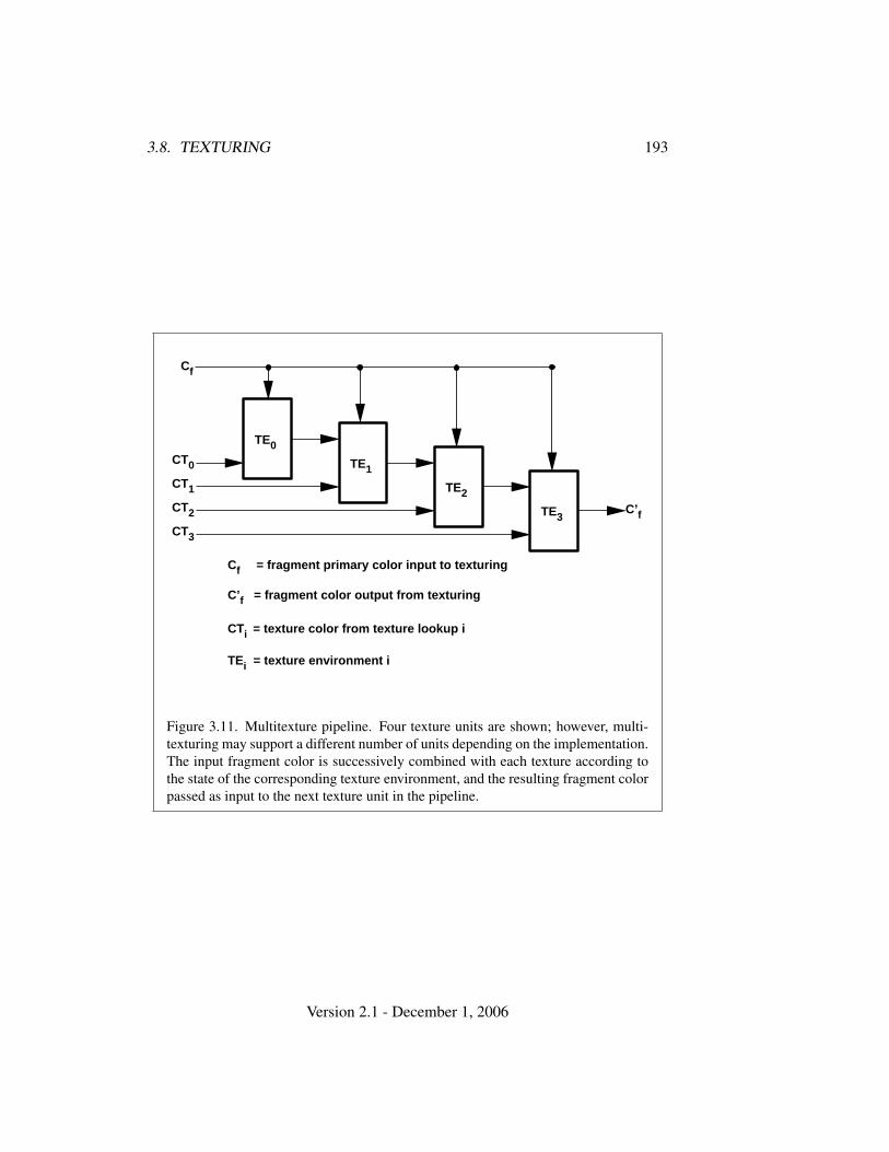
3.8. TEXTURING 193
TE0
TE1
TE2
TE3
CT0
CT1
CT2
CT3
C’f
CTi = texture color from texture lookup i
Cf = fragment primary color input to texturing
C’f = fragment color output from texturing
TEi = texture environment i
Cf
Figure 3.11. Multitexture pipeline. Four texture units are shown; however, multi-texturing may support a different number of units depending on the implementation.The input fragment color is successively combined with each texture according tothe state of the corresponding texture environment, and the resulting fragment colorpassed as input to the next texture unit in the pipeline.
Version 2.1 - December 1, 2006
194 CHAPTER 3. RASTERIZATION
3.9 Color Sum
At the beginning of color sum, a fragment has two RGBA colors: a primary colorcpri (which texturing, if enabled, may have modified) and a secondary color csec.
If color sum is enabled, the R, G, and B components of these two colors aresummed to produce a single post-texturing RGBA color c. The A component of cis taken from the A component of cpri; the A component of csec is unused. Thecomponents of c are then clamped to the range [0, 1]. If color sum is disabled, thencpri is assigned to c.
Color sum is enabled or disabled using the generic Enable and Disable com-mands, respectively, with the symbolic constant COLOR SUM. If lighting is enabledand if a vertex shader is not active, the color sum stage is always applied, ignoringthe value of COLOR SUM.
The state required is a single bit indicating whether color sum is enabled ordisabled. In the initial state, color sum is disabled.
Color sum has no effect in color index mode, or if a fragment shader is active.
3.10 Fog
If enabled, fog blends a fog color with a rasterized fragment’s post-texturing colorusing a blending factor f . Fog is enabled and disabled with the Enable and Disablecommands using the symbolic constant FOG.
This factor f is computed according to one of three equations:
f = exp(−d · c), (3.31)
f = exp(−(d · c)2), or (3.32)
f =e− c
e− s(3.33)
If a vertex shader is active, or if the fog source, as defined below, is FOG COORD,then c is the interpolated value of the fog coordinate for this fragment. Otherwise,if the fog source is FRAGMENT DEPTH, then c is the eye-coordinate distance fromthe eye, (0, 0, 0, 1) in eye coordinates, to the fragment center. The equation and thefog source, along with either d or e and s, is specified with
void Fog{if}( enum pname, T param );void Fog{if}v( enum pname, T params );
Version 2.1 - December 1, 2006
3.10. FOG 195
If pname is FOG MODE, then param must be, or params must point to an inte-ger that is one of the symbolic constants EXP, EXP2, or LINEAR, in which caseequation 3.31, 3.32, or 3.33, respectively, is selected for the fog calculation (if,when 3.33 is selected, e = s, results are undefined). If pname is FOG COORD SRC,then param must be, or params must point to an integer that is one of the sym-bolic constants FRAGMENT DEPTH or FOG COORD. If pname is FOG DENSITY,FOG START, or FOG END, then param is or params points to a value that is d, s,or e, respectively. If d is specified less than zero, the error INVALID VALUE re-sults.
An implementation may choose to approximate the eye-coordinate distancefrom the eye to each fragment center by |ze|. Further, f need not be computed ateach fragment, but may be computed at each vertex and interpolated as other dataare.
No matter which equation and approximation is used to compute f , the resultis clamped to [0, 1] to obtain the final f .
f is used differently depending on whether the GL is in RGBA or color indexmode. In RGBA mode, if Cr represents a rasterized fragment’s R, G, or B value,then the corresponding value produced by fog is
C = fCr + (1− f)Cf .
(The rasterized fragment’s A value is not changed by fog blending.) The R, G, B,and A values of Cf are specified by calling Fog with pname equal to FOG COLOR;in this case params points to four values comprising Cf . If these are not floating-point values, then they are converted to floating-point using the conversion givenin table 2.9 for signed integers. Each component of Cf is clamped to [0, 1] whenspecified.
In color index mode, the formula for fog blending is
I = ir + (1− f)if
where ir is the rasterized fragment’s color index and if is a single-precisionfloating-point value. (1 − f)if is rounded to the nearest fixed-point value withthe same number of bits to the right of the binary point as ir, and the integer por-tion of I is masked (bitwise ANDed) with 2n− 1, where n is the number of bits ina color in the color index buffer (buffers are discussed in chapter 4). The value ofif is set by calling Fog with pname set to FOG INDEX and param being or paramspointing to a single value for the fog index. The integer part of if is masked with2n − 1.
The state required for fog consists of a three valued integer to select the fogequation, three floating-point values d, e, and s, an RGBA fog color and a fog
Version 2.1 - December 1, 2006
196 CHAPTER 3. RASTERIZATION
color index, a two-valued integer to select the fog coordinate source, and a singlebit to indicate whether or not fog is enabled. In the initial state, fog is disabled,FOG COORD SRC is FRAGMENT DEPTH, FOG MODE is EXP, d = 1.0, e = 1.0, ands = 0.0; Cf = (0, 0, 0, 0) and if = 0.
Fog has no effect if a fragment shader is active.
3.11 Fragment Shaders
The sequence of operations that are applied to fragments that result from raster-izing a point, line segment, polygon, pixel rectangle or bitmap as described insections 3.8 through 3.10 is a fixed functionality method for processing such frag-ments. Applications can more generally describe the operations that occur on suchfragments by using a fragment shader.
A fragment shader is an array of strings containing source code for the opera-tions that are meant to occur on each fragment that results from rasterizing a point,line segment, polygon, pixel rectangle or bitmap. The language used for fragmentshaders is described in the OpenGL Shading Language Specification.
A fragment shader only applies when the GL is in RGBA mode. Its operationin color index mode is undefined.
Fragment shaders are created as described in section 2.15.1 using a type pa-rameter of FRAGMENT SHADER. They are attached to and used in program objectsas described in section 2.15.2.
When the program object currently in use includes a fragment shader, its frag-ment shader is considered active, and is used to process fragments. If the programobject has no fragment shader, or no program object is currently in use, the fixed-function fragment processing operations described in previous sections are used.
3.11.1 Shader Variables
Fragment shaders can access uniforms belonging to the current shader object. Theamount of storage available for fragment shader uniform variables is specified bythe implementation dependent constant MAX FRAGMENT UNIFORM COMPONENTS.This value represents the number of individual floating-point, integer, or booleanvalues that can be held in uniform variable storage for a fragment shader. A linkerror will be generated if an attempt is made to utilize more than the space availablefor fragment shader uniform variables.
Fragment shaders can read varying variables that correspond to the attributesof the fragments produced by rasterization. The OpenGL Shading Language Spec-ification defines a set of built-in varying variables that can be be accessed by a
Version 2.1 - December 1, 2006

3.11. FRAGMENT SHADERS 197
fragment shader. These built-in varying variables include the data associated witha fragment that are used for fixed-function fragment processing, such as the frag-ment’s position, color, secondary color, texture coordinates, fog coordinate, andeye z coordinate.
Additionally, when a vertex shader is active, it may define one or more varyingvariables (see section 2.15.3 and the OpenGL Shading Language Specification).These values are interpolated across the primitive being rendered. The results ofthese interpolations are available when varying variables of the same name aredefined in the fragment shader.
User-defined varying variables are not saved in the current raster position.When processing fragments generated by the rasterization of a pixel rectangle orbitmap, that values of user-defined varying variables are undefined. Built-in vary-ing variables have well-defined values.
3.11.2 Shader Execution
If a fragment shader is active, the executable version of the fragment shader is usedto process incoming fragment values that are the result of point, line segment, poly-gon, pixel rectangle or bitmap rasterization rather than the fixed-function fragmentprocessing described in sections 3.8 through 3.10. In particular,
• The texture environments and texture functions described in section 3.8.13are not applied.
• Texture application as described in section 3.8.16 is not applied.
• Color sum as described in section 3.9 is not applied.
• Fog as described in section 3.10 is not applied.
Texture Access
When a texture lookup is performed in a fragment shader, the GL computes thefiltered texture value τ in the manner described in sections 3.8.8 and 3.8.9, andconverts it to a texture source color Cs according to table 3.20 (section 3.8.13).The GL returns a four-component vector (Rs, Gs, Bs, As) to the fragment shader.For the purposes of level-of-detail calculations, the derivates du
dx , dudy , dv
dx , dvdy , dw
dx
and dwdy may be approximated by a differencing algorithm as detailed in section 8.8
of the OpenGL Shading Language specification.
Version 2.1 - December 1, 2006
198 CHAPTER 3. RASTERIZATION
Texture lookups involving textures with depth component data can either re-turn the depth data directly or return the results of a comparison with the r tex-ture coordinate used to perform the lookup. The comparison operation is re-quested in the shader by using the shadow sampler types (sampler1DShadowor sampler2DShadow) and in the texture using the TEXTURE COMPARE MODE pa-rameter. These requests must be consistent; the results of a texture lookup areundefined if:
• The sampler used in a texture lookup function is of type sampler1D orsampler2D, and the texture object’s internal format is DEPTH COMPONENT,and the TEXTURE COMPARE MODE is not NONE.
• The sampler used in a texture lookup function is of type sampler1DShadowor sampler2DShadow, and the texture object’s internal format isDEPTH COMPONENT, and the TEXTURE COMPARE MODE is NONE.
• The sampler used in a texture lookup function is of type sampler1DShadowor sampler2DShadow, and the texture object’s internal format is notDEPTH COMPONENT.
If a fragment shader uses a sampler whose associated texture object is not com-plete, as defined in section 3.8.10, the texture image unit will return (R,G,B,A)= (0, 0, 0, 1).
The number of separate texture units that can be accessed from within afragment shader during the rendering of a single primitive is specified by theimplementation- dependent constant MAX TEXTURE IMAGE UNITS.
Shader Inputs
The OpenGL Shading Language specification describes the values that are avail-able as inputs to the fragment shader.
The built-in variable gl FragCoord holds the window coordinates x, y, z,and 1
w for the fragment. The z component of gl FragCoord undergoes an im-plied conversion to floating-point. This conversion must leave the values 0 and1 invariant. Note that this z component already has a polygon offset added in, ifenabled (see section 3.5.5. The 1
w value is computed from the wc coordinate (seesection 2.11), which is the result of the product of the projection matrix and thevertex’s eye coordinates.
The built-in variables gl Color and gl SecondaryColor hold the R, G, B,and A components, respectively, of the fragment color and secondary color. Each
Version 2.1 - December 1, 2006
3.11. FRAGMENT SHADERS 199
fixed-point color component undergoes an implied conversion to floating-point.This conversion must leave the values 0 and 1 invariant.
The built-in variable gl FrontFacing is set to TRUE if the fragment is gener-ated from a front facing primitive, and FALSE otherwise. For fragments generatedfrom polygon, triangle, or quadrilateral primitives (including ones resulting frompolygons rendered as points or lines), the determination is made by examining thesign of the area computed by equation 2.6 of section 2.14.1 (including the possiblereversal of this sign controlled by FrontFace). If the sign is positive, fragmentsgenerated by the primitive are front facing; otherwise, they are back facing. Allother fragments are considered front facing.
Shader Outputs
The OpenGL Shading Language specification describes the values that may beoutput by a fragment shader. These are gl FragColor, gl FragData[n], andgl FragDepth. The final fragment color values or the final fragment data valueswritten by a fragment shader are clamped to the range [0, 1] and then converted tofixed-point as described in section 2.14.9. The final fragment depth written by afragment shader is first clamped to [0, 1] and then converted to fixed-point as if itwere a window z value (see section 2.11.1). Note that the depth range computationis not applied here, only the conversion to fixed-point.
Writing to gl FragColor specifies the fragment color (color numberzero) that will be used by subsequent stages of the pipeline. Writing togl FragData[n] specifies the value of fragment color number n. Any colors,or color components, associated with a fragment that are not written by the frag-ment shader are undefined. A fragment shader may not statically assign values toboth gl FragColor and gl FragData. In this case, a compile or link error willresult. A shader statically assigns a value to a variable if, after pre-processing, itcontains a statement that would write to the variable, whether or not run-time flowof control will cause that statement to be executed.
Writing to gl FragDepth specifies the depth value for the fragment beingprocessed. If the active fragment shader does not statically assign a value togl FragDepth, then the depth value generated during rasterization is used by sub-sequent stages of the pipeline. Otherwise, the value assigned to gl FragDepth isused, and is undefined for any fragments where statements assigning a value togl FragDepth are not executed. Thus, if a shader statically assigns a value togl FragDepth, then it is responsible for always writing it.
Version 2.1 - December 1, 2006
200 CHAPTER 3. RASTERIZATION
3.12 Antialiasing Application
If antialiasing is enabled for the primitive from which a rasterized fragment wasproduced, then the computed coverage value is applied to the fragment. In RGBAmode, the value is multiplied by the fragment’s alpha (A) value to yield a finalalpha value. In color index mode, the value is used to set the low order bits ofthe color index value as described in section 3.2. The coverage value is appliedseparately to each fragment color.
3.13 Multisample Point Fade
Finally, if multisampling is enabled and the rasterized fragment results from a pointprimitive, then the computed fade factor from equation 3.2 is applied to the frag-ment. In RGBA mode, the fade factor is multiplied by the fragment’s alpha valueto yield a final alpha value. In color index mode, the fade factor has no effect. Thefade factor is applied separately to each fragment color.
Version 2.1 - December 1, 2006
Chapter 4
Per-Fragment Operations and theFramebuffer
The framebuffer consists of a set of pixels arranged as a two-dimensional array.The height and width of this array may vary from one GL implementation to an-other. For purposes of this discussion, each pixel in the framebuffer is simply a setof some number of bits. The number of bits per pixel may also vary depending onthe particular GL implementation or context.
Corresponding bits from each pixel in the framebuffer are grouped togetherinto a bitplane; each bitplane contains a single bit from each pixel. These bitplanesare grouped into several logical buffers. These are the color, depth, stencil, andaccumulation buffers. The color buffer actually consists of a number of buffers:the front left buffer, the front right buffer, the back left buffer, the back right buffer,and some number of auxiliary buffers. Typically the contents of the front buffersare displayed on a color monitor while the contents of the back buffers are invisi-ble. (Monoscopic contexts display only the front left buffer; stereoscopic contextsdisplay both the front left and the front right buffers.) The contents of the aux-iliary buffers are never visible. All color buffers must have the same number ofbitplanes, although an implementation or context may choose not to provide rightbuffers, back buffers, or auxiliary buffers at all. Further, an implementation orcontext may not provide depth, stencil, or accumulation buffers.
Color buffers consist of either unsigned integer color indices or R, G, B, and,optionally, A unsigned integer values. The number of bitplanes in each of the colorbuffers, the depth buffer, the stencil buffer, and the accumulation buffer is fixed andwindow dependent. If an accumulation buffer is provided, it must have at least asmany bitplanes per R, G, and B color component as do the color buffers.
The initial state of all provided bitplanes is undefined.
201
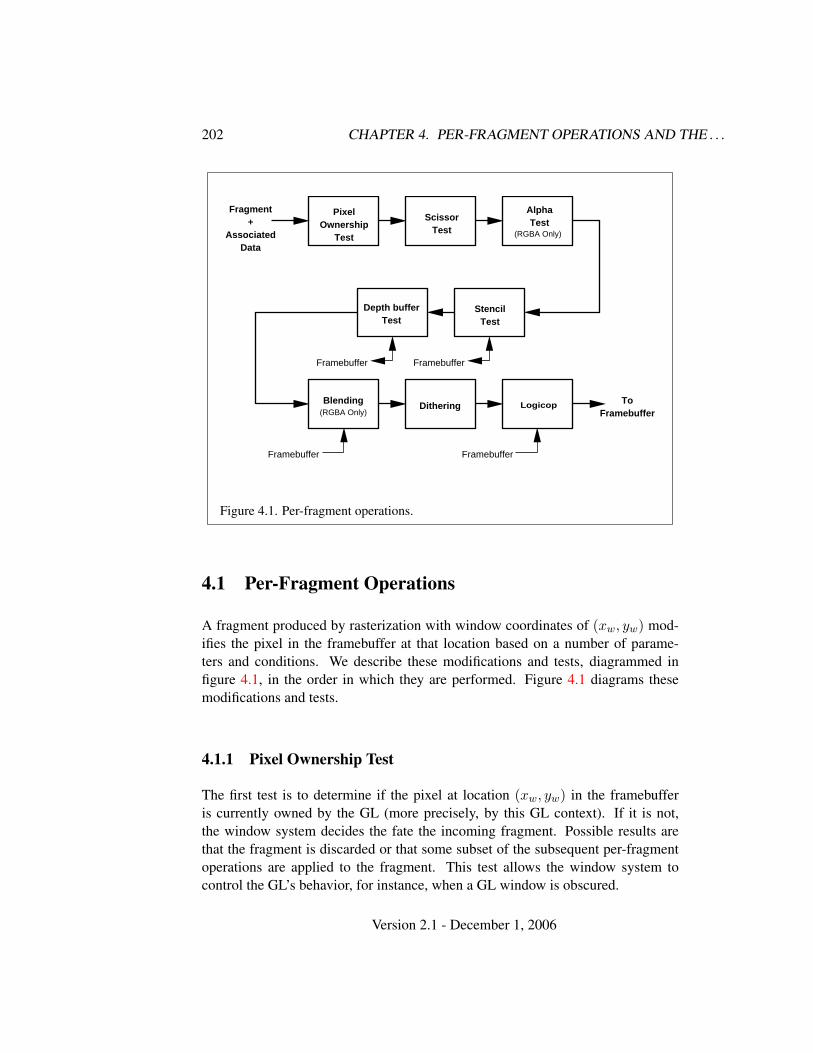
202 CHAPTER 4. PER-FRAGMENT OPERATIONS AND THE . . .
Fragment+
AssociatedData
PixelOwnership
Test
ScissorTest
Stencil Test
Framebuffer
AlphaTest
Depth bufferTest
Blending(RGBA Only)
Dithering
Framebuffer
Framebuffer
Logicop ToFramebuffer
Framebuffer
(RGBA Only)
Figure 4.1. Per-fragment operations.
4.1 Per-Fragment Operations
A fragment produced by rasterization with window coordinates of (xw, yw) mod-ifies the pixel in the framebuffer at that location based on a number of parame-ters and conditions. We describe these modifications and tests, diagrammed infigure 4.1, in the order in which they are performed. Figure 4.1 diagrams thesemodifications and tests.
4.1.1 Pixel Ownership Test
The first test is to determine if the pixel at location (xw, yw) in the framebufferis currently owned by the GL (more precisely, by this GL context). If it is not,the window system decides the fate the incoming fragment. Possible results arethat the fragment is discarded or that some subset of the subsequent per-fragmentoperations are applied to the fragment. This test allows the window system tocontrol the GL’s behavior, for instance, when a GL window is obscured.
Version 2.1 - December 1, 2006
4.1. PER-FRAGMENT OPERATIONS 203
4.1.2 Scissor Test
The scissor test determines if (xw, yw) lies within the scissor rectangle defined byfour values. These values are set with
void Scissor( int left, int bottom, sizei width,sizei height );
If left ≤ xw < left + width and bottom ≤ yw < bottom + height, then the scissortest passes. Otherwise, the test fails and the fragment is discarded. The test isenabled or disabled using Enable or Disable using the constant SCISSOR TEST.When disabled, it is as if the scissor test always passes. If either width or heightis less than zero, then the error INVALID VALUE is generated. The state requiredconsists of four integer values and a bit indicating whether the test is enabled ordisabled. In the initial state left = bottom = 0; width and height are determinedby the size of the GL window. Initially, the scissor test is disabled.
4.1.3 Multisample Fragment Operations
This step modifies fragment alpha and coverage values based on the valuesof SAMPLE ALPHA TO COVERAGE, SAMPLE ALPHA TO ONE, SAMPLE COVERAGE,SAMPLE COVERAGE VALUE, and SAMPLE COVERAGE INVERT. No changes to thefragment alpha or coverage values are made at this step if MULTISAMPLE is dis-abled, or if the value of SAMPLE BUFFERS is not one.
SAMPLE ALPHA TO COVERAGE, SAMPLE ALPHA TO ONE, andSAMPLE COVERAGE are enabled and disabled by calling Enable and Disablewith cap specified as one of the three token values. All three values arequeried by calling IsEnabled with cap set to the desired token value. IfSAMPLE ALPHA TO COVERAGE is enabled, a temporary coverage value is gen-erated where each bit is determined by the alpha value at the correspondingsample location. The temporary coverage value is then ANDed with the fragmentcoverage value. Otherwise the fragment coverage value is unchanged at this point.If multiple colors are written by a fragment shader, the alpha value of fragmentcolor zero is used to determine the temporary coverage value.
No specific algorithm is required for converting the sample alpha values to atemporary coverage value. It is intended that the number of 1’s in the temporarycoverage be proportional to the set of alpha values for the fragment, with all 1’scorresponding to the maximum of all alpha values, and all 0’s corresponding toall alpha values being 0. It is also intended that the algorithm be pseudo-randomin nature, to avoid image artifacts due to regular coverage sample locations. Thealgorithm can and probably should be different at different pixel locations. If it
Version 2.1 - December 1, 2006
204 CHAPTER 4. PER-FRAGMENT OPERATIONS AND THE . . .
does differ, it should be defined relative to window, not screen, coordinates, so thatrendering results are invariant with respect to window position.
Next, if SAMPLE ALPHA TO ONE is enabled, each alpha value is replaced by themaximum representable alpha value. Otherwise, the alpha values are not changed.
Finally, if SAMPLE COVERAGE is enabled, the fragment coverage is ANDedwith another temporary coverage. This temporary coverage is generatedin the same manner as the one described above, but as a function ofthe value of SAMPLE COVERAGE VALUE. The function need not be identical,but it must have the same properties of proportionality and invariance. IfSAMPLE COVERAGE INVERT is TRUE, the temporary coverage is inverted (all bitvalues are inverted) before it is ANDed with the fragment coverage.
The values of SAMPLE COVERAGE VALUE and SAMPLE COVERAGE INVERT
are specified by calling
void SampleCoverage( clampf value, boolean invert );
with value set to the desired coverage value, and invert set to TRUE or FALSE.value is clamped to [0,1] before being stored as SAMPLE COVERAGE VALUE.SAMPLE COVERAGE VALUE is queried by calling GetFloatv with pname set toSAMPLE COVERAGE VALUE. SAMPLE COVERAGE INVERT is queried by callingGetBooleanv with pname set to SAMPLE COVERAGE INVERT.
4.1.4 Alpha Test
This step applies only in RGBA mode. In color index mode, proceed to the nextoperation. The alpha test discards a fragment conditional on the outcome of acomparison between the incoming fragment’s alpha value and a constant value. Ifmultiple colors are written by a fragment shader, the alpha value of fragment colorzero is used to determine the result of the alpha test. The comparison is enabledor disabled with the generic Enable and Disable commands using the symbolicconstant ALPHA TEST. When disabled, it is as if the comparison always passes.The test is controlled with
void AlphaFunc( enum func, clampf ref );
func is a symbolic constant indicating the alpha test function; ref is a referencevalue. ref is clamped to lie in [0, 1], and then converted to a fixed-point value ac-cording to the rules given for an A component in section 2.14.9. For purposesof the alpha test, the fragment’s alpha value is also rounded to the nearest inte-ger. The possible constants specifying the test function are NEVER, ALWAYS, LESS,LEQUAL, EQUAL, GEQUAL, GREATER, or NOTEQUAL, meaning pass the fragment
Version 2.1 - December 1, 2006
4.1. PER-FRAGMENT OPERATIONS 205
never, always, if the fragment’s alpha value is less than, less than or equal to, equalto, greater than or equal to, greater than, or not equal to the reference value, respec-tively.
The required state consists of the floating-point reference value, an eight-valued integer indicating the comparison function, and a bit indicating if the com-parison is enabled or disabled. The initial state is for the reference value to be 0and the function to be ALWAYS. Initially, the alpha test is disabled.
4.1.5 Stencil Test
The stencil test conditionally discards a fragment based on the outcome of a com-parison between the value in the stencil buffer at location (xw, yw) and a referencevalue. The test is enabled or disabled with the Enable and Disable commands,using the symbolic constant STENCIL TEST. When disabled, the stencil test andassociated modifications are not made, and the fragment is always passed.
The stencil test is controlled with
void StencilFunc( enum func, int ref, uint mask );void StencilFuncSeparate( enum face, enum func, int ref,
uint mask );void StencilOp( enum sfail, enum dpfail, enum dppass );void StencilOpSeparate( enum face, enum sfail, enum dpfail,
enum dppass );
There are two sets of stencil-related state, the front stencil state set and the backstencil state set. Stencil tests and writes use the front set of stencil state when pro-cessing fragments rasterized from non-polygon primitives (points, lines, bitmaps,image rectangles) and front-facing polygon primitives while the back set of stencilstate is used when processing fragments rasterized from back-facing polygon prim-itives. For the purposes of stencil testing, a primitive is still considered a polygoneven if the polygon is to be rasterized as points or lines due to the current poly-gon mode. Whether a polygon is front- or back-facing is determined in the samemanner used for two-sided lighting and face culling (see sections 2.14.1 and 3.5.1).
StencilFuncSeparate and StencilOpSeparate take a face argument which canbe FRONT, BACK, or FRONT AND BACK and indicates which set of state is affected.StencilFunc and StencilOp set front and back stencil state to identical values.
StencilFunc and StencilFuncSeparate take three arguments that controlwhether the stencil test passes or fails. ref is an integer reference value that isused in the unsigned stencil comparison. It is clamped to the range [0, 2s − 1],where s is the number of bits in the stencil buffer. The s least significant bits of
Version 2.1 - December 1, 2006
206 CHAPTER 4. PER-FRAGMENT OPERATIONS AND THE . . .
mask are bitwise ANDed with both the reference and the stored stencil value, andthe resulting masked values are those that participate in the comparison controlledby func. func is a symbolic constant that determines the stencil comparison func-tion; the eight symbolic constants are NEVER, ALWAYS, LESS, LEQUAL, EQUAL,GEQUAL, GREATER, or NOTEQUAL. Accordingly, the stencil test passes never, al-ways, and if the masked reference value is less than, less than or equal to, equal to,greater than or equal to, greater than, or not equal to the masked stored value in thestencil buffer.
StencilOp and StencilOpSeparate take three arguments that indicate whathappens to the stored stencil value if this or certain subsequent tests fail or pass.sfail indicates what action is taken if the stencil test fails. The symbolic constantsare KEEP, ZERO, REPLACE, INCR, DECR, INVERT, INCR WRAP, and DECR WRAP.These correspond to keeping the current value, setting to zero, replacing with thereference value, incrementing with saturation, decrementing with saturation, bit-wise inverting it, incrementing without saturation, and decrementing without satu-ration.
For purposes of increment and decrement, the stencil bits are considered as anunsigned integer. Incrementing or decrementing with saturation clamps the stencilvalue at 0 and the maximum representable value. Incrementing or decrementingwithout saturation will wrap such that incrementing the maximum representablevalue results in 0, and decrementing 0 results in the maximum representable value.
The same symbolic values are given to indicate the stencil action if the depthbuffer test (see section 4.1.6) fails (dpfail), or if it passes (dppass).
If the stencil test fails, the incoming fragment is discarded. The state requiredconsists of the most recent values passed to StencilFunc or StencilFuncSeparateand to StencilOp or StencilOpSeparate, and a bit indicating whether stencil test-ing is enabled or disabled. In the initial state, stenciling is disabled, the front andback stencil reference value are both zero, the front and back stencil comparisonfunctions are both ALWAYS, and the front and back stencil mask are both all ones.Initially, all three front and back stencil operations are KEEP.
If there is no stencil buffer, no stencil modification can occur, and it is as if thestencil tests always pass, regardless of any calls to StencilFunc.
4.1.6 Depth Buffer Test
The depth buffer test discards the incoming fragment if a depth comparison fails.The comparison is enabled or disabled with the generic Enable and Disable com-mands using the symbolic constant DEPTH TEST. When disabled, the depth com-parison and subsequent possible updates to the depth buffer value are bypassed andthe fragment is passed to the next operation. The stencil value, however, is modi-
Version 2.1 - December 1, 2006
4.1. PER-FRAGMENT OPERATIONS 207
fied as indicated below as if the depth buffer test passed. If enabled, the comparisontakes place and the depth buffer and stencil value may subsequently be modified.
The comparison is specified with
void DepthFunc( enum func );
This command takes a single symbolic constant: one of NEVER, ALWAYS, LESS,LEQUAL, EQUAL, GREATER, GEQUAL, NOTEQUAL. Accordingly, the depth buffertest passes never, always, if the incoming fragment’s zw value is less than, lessthan or equal to, equal to, greater than, greater than or equal to, or not equal tothe depth value stored at the location given by the incoming fragment’s (xw, yw)coordinates.
If the depth buffer test fails, the incoming fragment is discarded. The stencilvalue at the fragment’s (xw, yw) coordinates is updated according to the functioncurrently in effect for depth buffer test failure. Otherwise, the fragment continuesto the next operation and the value of the depth buffer at the fragment’s (xw, yw)location is set to the fragment’s zw value. In this case the stencil value is updatedaccording to the function currently in effect for depth buffer test success.
The necessary state is an eight-valued integer and a single bit indicatingwhether depth buffering is enabled or disabled. In the initial state the functionis LESS and the test is disabled.
If there is no depth buffer, it is as if the depth buffer test always passes.
4.1.7 Occlusion Queries
Occlusion queries can be used to track the number of fragments or samples thatpass the depth test.
Occlusion queries are associated with query objects.An occlusion query can be started and finished by calling
void BeginQuery( enum target, uint id );void EndQuery( enum target );
where target is SAMPLES PASSED. If BeginQuery is called with an unused id, thatname is marked as used and associated with a new query object.
BeginQuery with a target of SAMPLES PASSED resets the current samples-passed count to zero and sets the query active state to TRUE and the active queryid to id. EndQuery with a target of SAMPLES PASSED initializes a copy of thecurrent samples-passed count into the active occlusion query object’s results value,sets the active occlusion query object’s result available to FALSE, sets the queryactive state to FALSE, and the active query id to 0.
Version 2.1 - December 1, 2006
208 CHAPTER 4. PER-FRAGMENT OPERATIONS AND THE . . .
If BeginQuery is called with an id of zero, while another query is already inprogress with the same target, or where id is the name of a query currently inprogress, an INVALID OPERATION error is generated.
If EndQuery is called while no query with the same target is in progress, anINVALID OPERATION error is generated.
When an occlusion query is active, the samples-passed count increases bya certain quantity for each fragment that passes the depth test. If the value ofSAMPLE BUFFERS is 0, then the samples-passed count increases by 1 for eachfragment. If the value of SAMPLE BUFFERS is 1, then the samples-passed countincreases by the number of samples whose coverage bit is set. However, imple-mentations, at their discretion, are allowed to instead increase the samples-passedcount by the value of SAMPLES if any sample in the fragment is covered.
If the samples-passed count overflows, i.e., exceeds the value 2n − 1 (where nis the number of bits in the samples-passed count), its value becomes undefined. Itis recommended, but not required, that implementations handle this overflow caseby saturating at 2n − 1 and incrementing no further.
The command
void GenQueries( sizei n, uint *ids );
returns n previously unused query object names in ids. These names are markedas used, but no object is associated with them until the first time they are used byBeginQuery. Query objects contain one piece of state, an integer result value. Thisresult value is initialized to zero when the object is created. Any positive integerexcept for zero (which is reserved for the GL) is a valid query object name.
Query objects are deleted by calling
void DeleteQueries( sizei n, const uint *ids );
ids contains n names of query objects to be deleted. After a query object is deleted,its name is again unused. Unused names in ids are silently ignored.
Calling either GenQueries or DeleteQueries while any query of any target isactive causes an INVALID OPERATION error to be generated.
The necessary state is a single bit indicating whether an occlusion query isactive, the identifier of the currently active occlusion query, and a counter keepingtrack of the number of samples that have passed.
4.1.8 Blending
Blending combines the incoming source fragment’s R, G, B, and A values withthe destination R, G, B, and A values stored in the framebuffer at the fragment’s(xw, yw) location.
Version 2.1 - December 1, 2006

4.1. PER-FRAGMENT OPERATIONS 209
Source and destination values are combined according to the blend equation,quadruplets of source and destination weighting factors determined by the blendfunctions, and a constant blend color to obtain a new set of R, G, B, and A values,as described below. Each of these floating-point values is clamped to [0, 1] andconverted back to a fixed-point value in the manner described in section 2.14.9.The resulting four values are sent to the next operation.
Blending is dependent on the incoming fragment’s alpha value and that of thecorresponding currently stored pixel. Blending applies only in RGBA mode; incolor index mode it is bypassed. Blending is enabled or disabled using Enable orDisable with the symbolic constant BLEND. If it is disabled, or if logical operationon color values is enabled (section 4.1.10), proceed to the next operation.
If multiple fragment colors are being written to multiple buffers (see sec-tion 4.2.1), blending is computed and applied separately for each fragment colorand the corresponding buffer.
Blend Equation
Blending is controlled by the blend equations, defined by the commands
void BlendEquation( enum mode );void BlendEquationSeparate( enum modeRGB,
enum modeAlpha );
BlendEquationSeparate argument modeRGB determines the RGB blend func-tion while modeAlpha determines the alpha blend equation. BlendEqua-tion argument mode determines both the RGB and alpha blend equations.modeRGB and modeAlpha must each be one of FUNC ADD, FUNC SUBTRACT,FUNC REVERSE SUBTRACT, MIN, or MAX.
Destination (framebuffer) components are taken to be fixed-point values rep-resented according to the scheme in section 2.14.9 (Final Color Processing), asare source (fragment) components. Constant color components are taken to befloating-point values.
Prior to blending, each fixed-point color component undergoes an implied con-version to floating-point. This conversion must leave the values 0 and 1 invariant.Blending components are treated as if carried out in floating-point.
Table 4.1 provides the corresponding per-component blend equations for eachmode, whether acting on RGB components for modeRGB or the alpha componentfor modeAlpha.
In the table, the s subscript on a color component abbreviation (R, G, B, orA) refers to the source color component for an incoming fragment, the d subscript
Version 2.1 - December 1, 2006
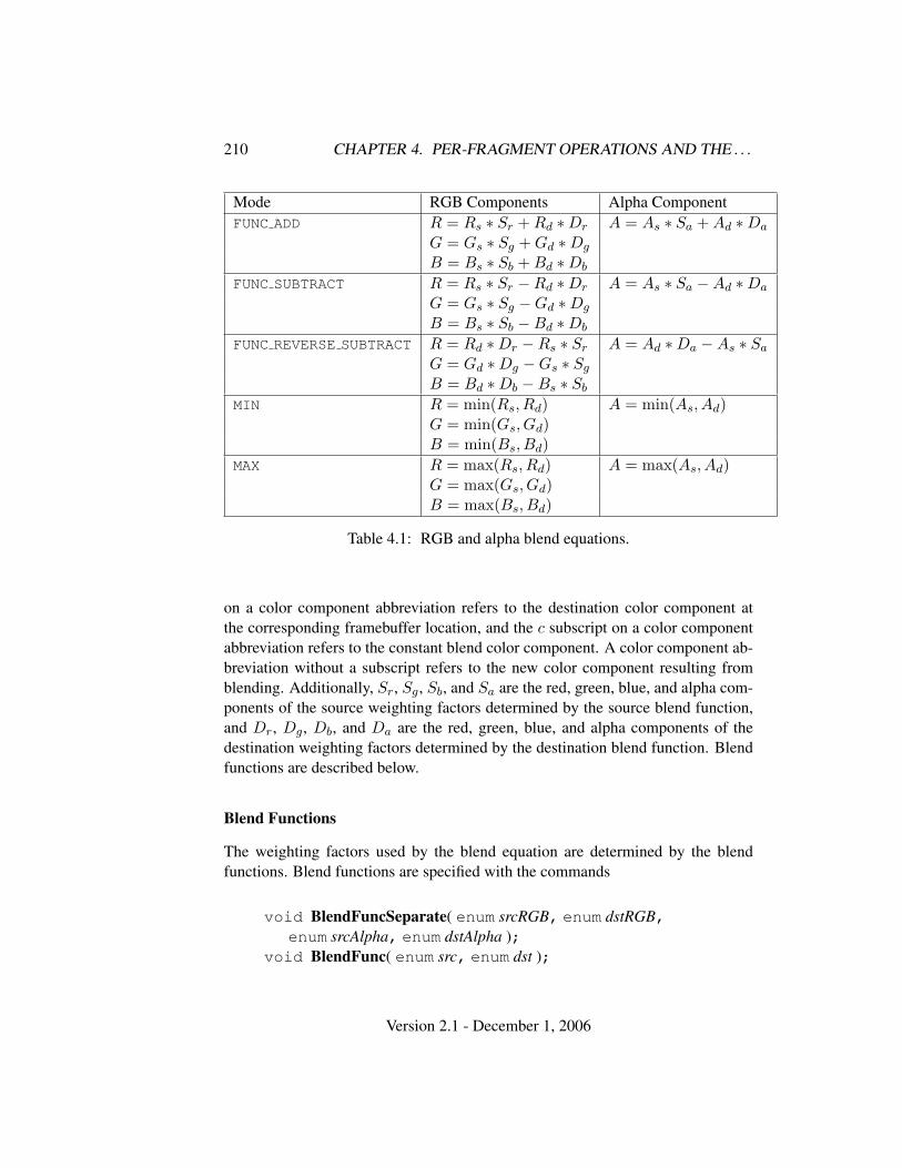
210 CHAPTER 4. PER-FRAGMENT OPERATIONS AND THE . . .
Mode RGB Components Alpha ComponentFUNC ADD R = Rs ∗ Sr + Rd ∗Dr A = As ∗ Sa + Ad ∗Da
G = Gs ∗ Sg + Gd ∗Dg
B = Bs ∗ Sb + Bd ∗Db
FUNC SUBTRACT R = Rs ∗ Sr −Rd ∗Dr A = As ∗ Sa −Ad ∗Da
G = Gs ∗ Sg −Gd ∗Dg
B = Bs ∗ Sb −Bd ∗Db
FUNC REVERSE SUBTRACT R = Rd ∗Dr −Rs ∗ Sr A = Ad ∗Da −As ∗ Sa
G = Gd ∗Dg −Gs ∗ Sg
B = Bd ∗Db −Bs ∗ Sb
MIN R = min(Rs, Rd) A = min(As, Ad)G = min(Gs, Gd)B = min(Bs, Bd)
MAX R = max(Rs, Rd) A = max(As, Ad)G = max(Gs, Gd)B = max(Bs, Bd)
Table 4.1: RGB and alpha blend equations.
on a color component abbreviation refers to the destination color component atthe corresponding framebuffer location, and the c subscript on a color componentabbreviation refers to the constant blend color component. A color component ab-breviation without a subscript refers to the new color component resulting fromblending. Additionally, Sr, Sg, Sb, and Sa are the red, green, blue, and alpha com-ponents of the source weighting factors determined by the source blend function,and Dr, Dg, Db, and Da are the red, green, blue, and alpha components of thedestination weighting factors determined by the destination blend function. Blendfunctions are described below.
Blend Functions
The weighting factors used by the blend equation are determined by the blendfunctions. Blend functions are specified with the commands
void BlendFuncSeparate( enum srcRGB, enum dstRGB,enum srcAlpha, enum dstAlpha );
void BlendFunc( enum src, enum dst );
Version 2.1 - December 1, 2006
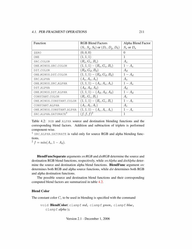
4.1. PER-FRAGMENT OPERATIONS 211
Function RGB Blend Factors Alpha Blend Factor(Sr, Sg, Sb) or (Dr, Dg, Db) Sa or Da
ZERO (0, 0, 0) 0ONE (1, 1, 1) 1SRC COLOR (Rs, Gs, Bs) As
ONE MINUS SRC COLOR (1, 1, 1)− (Rs, Gs, Bs) 1−As
DST COLOR (Rd, Gd, Bd) Ad
ONE MINUS DST COLOR (1, 1, 1)− (Rd, Gd, Bd) 1−Ad
SRC ALPHA (As, As, As) As
ONE MINUS SRC ALPHA (1, 1, 1)− (As, As, As) 1−As
DST ALPHA (Ad, Ad, Ad) Ad
ONE MINUS DST ALPHA (1, 1, 1)− (Ad, Ad, Ad) 1−Ad
CONSTANT COLOR (Rc, Gc, Bc) Ac
ONE MINUS CONSTANT COLOR (1, 1, 1)− (Rc, Gc, Bc) 1−Ac
CONSTANT ALPHA (Ac, Ac, Ac) Ac
ONE MINUS CONSTANT ALPHA (1, 1, 1)− (Ac, Ac, Ac) 1−Ac
SRC ALPHA SATURATE1 (f, f, f)2 1
Table 4.2: RGB and ALPHA source and destination blending functions and thecorresponding blend factors. Addition and subtraction of triplets is performedcomponent-wise.1 SRC ALPHA SATURATE is valid only for source RGB and alpha blending func-tions.2 f = min(As, 1−Ad).
BlendFuncSeparate arguments srcRGB and dstRGB determine the source anddestination RGB blend functions, respectively, while srcAlpha and dstAlpha deter-mine the source and destination alpha blend functions. BlendFunc argument srcdetermines both RGB and alpha source functions, while dst determines both RGBand alpha destination functions.
The possible source and destination blend functions and their correspondingcomputed blend factors are summarized in table 4.2.
Blend Color
The constant color Cc to be used in blending is specified with the command
void BlendColor( clampf red, clampf green, clampf blue,clampf alpha );
Version 2.1 - December 1, 2006
212 CHAPTER 4. PER-FRAGMENT OPERATIONS AND THE . . .
The four parameters are clamped to the range [0, 1] before being stored. Theconstant color can be used in both the source and destination blending functions
Blending State
The state required for blending is two integers for the RGB and alpha blend equa-tions, four integers indicating the source and destination RGB and alpha blendingfunctions, four floating-point values to store the RGBA constant blend color, and abit indicating whether blending is enabled or disabled. The initial blend equationsfor RGB and alpha are both FUNC ADD. The initial blending functions are ONE forthe source RGB and alpha functions and ZERO for the destination RGB and alphafunctions. The initial constant blend color is (R,G,B,A) = (0, 0, 0, 0). Initially,blending is disabled.
Blending occurs once for each color buffer currently enabled for writing (sec-tion 4.2.1) using each buffer’s color for Cd. If a color buffer has no A value, thenAd is taken to be 1.
4.1.9 Dithering
Dithering selects between two color values or indices. In RGBA mode, considerthe value of any of the color components as a fixed-point value with m bits to theleft of the binary point, where m is the number of bits allocated to that componentin the framebuffer; call each such value c. For each c, dithering selects a valuec1 such that c1 ∈ {max{0, dce − 1}, dce} (after this selection, treat c1 as a fixedpoint value in [0,1] with m bits). This selection may depend on the xw and yw
coordinates of the pixel. In color index mode, the same rule applies with c being asingle color index. c must not be larger than the maximum value representable inthe framebuffer for either the component or the index, as appropriate.
Many dithering algorithms are possible, but a dithered value produced by anyalgorithm must depend only the incoming value and the fragment’s x and y windowcoordinates. If dithering is disabled, then each color component is truncated to afixed-point value with as many bits as there are in the corresponding component inthe framebuffer; a color index is rounded to the nearest integer representable in thecolor index portion of the framebuffer.
Dithering is enabled with Enable and disabled with Disable using the symbolicconstant DITHER. The state required is thus a single bit. Initially, dithering isenabled.
Version 2.1 - December 1, 2006
4.1. PER-FRAGMENT OPERATIONS 213
4.1.10 Logical Operation
Finally, a logical operation is applied between the incoming fragment’s color orindex values and the color or index values stored at the corresponding location inthe framebuffer. The result replaces the values in the framebuffer at the fragment’s(xw, yw) coordinates. The logical operation on color indices is enabled or dis-abled with Enable or Disable using the symbolic constant INDEX LOGIC OP. (Forcompatibility with GL version 1.0, the symbolic constant LOGIC OP may also beused.) The logical operation on color values is enabled or disabled with Enable orDisable using the symbolic constant COLOR LOGIC OP. If the logical operation isenabled for color values, it is as if blending were disabled, regardless of the valueof BLEND. If multiple fragment colors are being written to multiple buffers (seesection 4.2.1), the logical operation is computed and applied separately for eachfragment color and the corresponding buffer.
The logical operation is selected by
void LogicOp( enum op );
op is a symbolic constant; the possible constants and corresponding operations areenumerated in table 4.3. In this table, s is the value of the incoming fragment and dis the value stored in the framebuffer. The numeric values assigned to the symbolicconstants are the same as those assigned to the corresponding symbolic values inthe X window system.
Logical operations are performed independently for each color index bufferthat is selected for writing, or for each red, green, blue, and alpha value of eachcolor buffer that is selected for writing. The required state is an integer indicatingthe logical operation, and two bits indicating whether the logical operation is en-abled or disabled. The initial state is for the logic operation to be given by COPY,and to be disabled.
4.1.11 Additional Multisample Fragment Operations
If the DrawBuffer mode is NONE, no change is made to any multisample or colorbuffer. Otherwise, fragment processing is as described below.
If MULTISAMPLE is enabled, and the value of SAMPLE BUFFERS is one, thealpha test, stencil test, depth test, blending, and dithering operations are performedfor each pixel sample, rather than just once for each fragment. Failure of the alpha,stencil, or depth test results in termination of the processing of that sample, ratherthan discarding of the fragment. All operations are performed on the color, depth,and stencil values stored in the multisample buffer (to be described in a followingsection). The contents of the color buffers are not modified at this point.
Version 2.1 - December 1, 2006
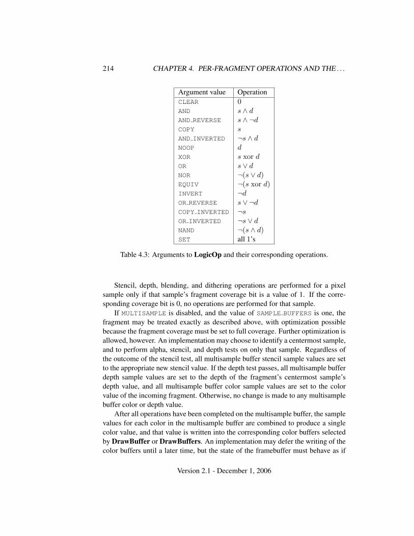
214 CHAPTER 4. PER-FRAGMENT OPERATIONS AND THE . . .
Argument value OperationCLEAR 0AND s ∧ dAND REVERSE s ∧ ¬dCOPY sAND INVERTED ¬s ∧ dNOOP dXOR s xor dOR s ∨ dNOR ¬(s ∨ d)EQUIV ¬(s xor d)INVERT ¬dOR REVERSE s ∨ ¬dCOPY INVERTED ¬sOR INVERTED ¬s ∨ dNAND ¬(s ∧ d)SET all 1’s
Table 4.3: Arguments to LogicOp and their corresponding operations.
Stencil, depth, blending, and dithering operations are performed for a pixelsample only if that sample’s fragment coverage bit is a value of 1. If the corre-sponding coverage bit is 0, no operations are performed for that sample.
If MULTISAMPLE is disabled, and the value of SAMPLE BUFFERS is one, thefragment may be treated exactly as described above, with optimization possiblebecause the fragment coverage must be set to full coverage. Further optimization isallowed, however. An implementation may choose to identify a centermost sample,and to perform alpha, stencil, and depth tests on only that sample. Regardless ofthe outcome of the stencil test, all multisample buffer stencil sample values are setto the appropriate new stencil value. If the depth test passes, all multisample bufferdepth sample values are set to the depth of the fragment’s centermost sample’sdepth value, and all multisample buffer color sample values are set to the colorvalue of the incoming fragment. Otherwise, no change is made to any multisamplebuffer color or depth value.
After all operations have been completed on the multisample buffer, the samplevalues for each color in the multisample buffer are combined to produce a singlecolor value, and that value is written into the corresponding color buffers selectedby DrawBuffer or DrawBuffers. An implementation may defer the writing of thecolor buffers until a later time, but the state of the framebuffer must behave as if
Version 2.1 - December 1, 2006
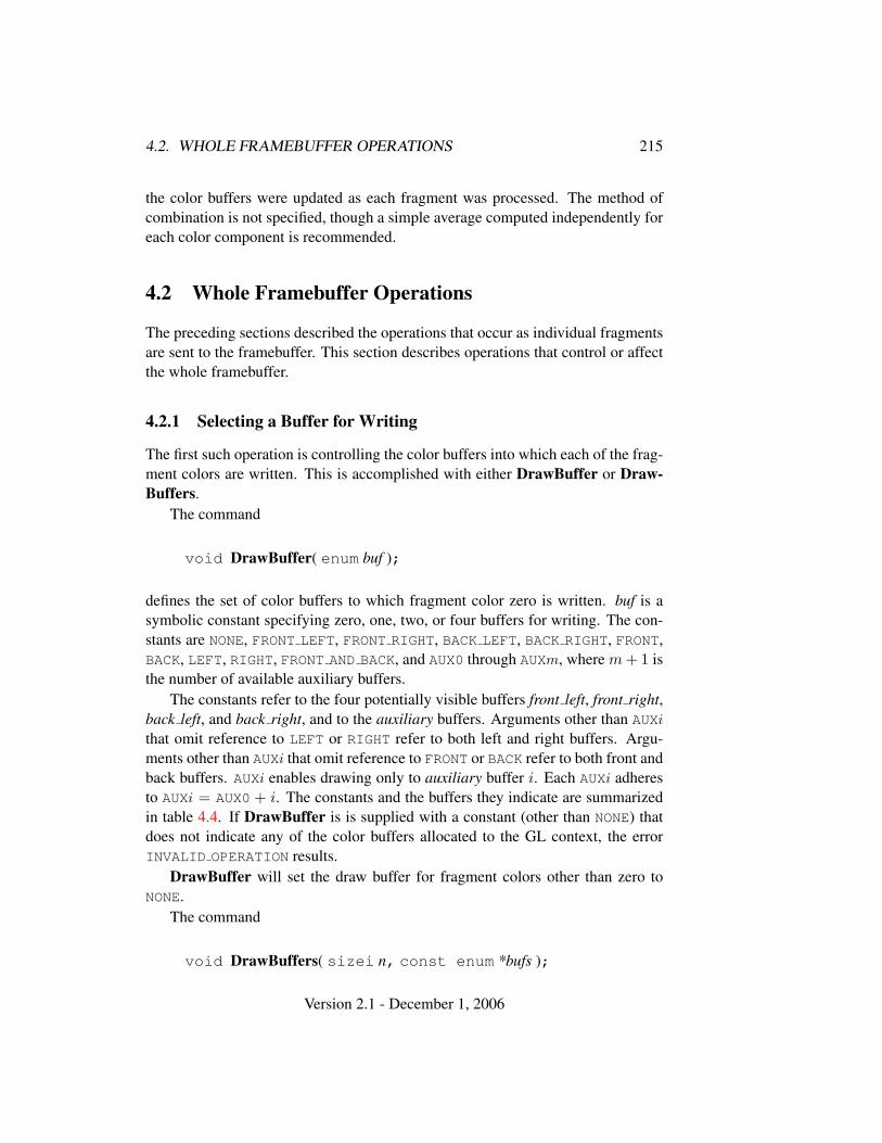
4.2. WHOLE FRAMEBUFFER OPERATIONS 215
the color buffers were updated as each fragment was processed. The method ofcombination is not specified, though a simple average computed independently foreach color component is recommended.
4.2 Whole Framebuffer Operations
The preceding sections described the operations that occur as individual fragmentsare sent to the framebuffer. This section describes operations that control or affectthe whole framebuffer.
4.2.1 Selecting a Buffer for Writing
The first such operation is controlling the color buffers into which each of the frag-ment colors are written. This is accomplished with either DrawBuffer or Draw-Buffers.
The command
void DrawBuffer( enum buf );
defines the set of color buffers to which fragment color zero is written. buf is asymbolic constant specifying zero, one, two, or four buffers for writing. The con-stants are NONE, FRONT LEFT, FRONT RIGHT, BACK LEFT, BACK RIGHT, FRONT,BACK, LEFT, RIGHT, FRONT AND BACK, and AUX0 through AUXm, where m + 1 isthe number of available auxiliary buffers.
The constants refer to the four potentially visible buffers front left, front right,back left, and back right, and to the auxiliary buffers. Arguments other than AUXi
that omit reference to LEFT or RIGHT refer to both left and right buffers. Argu-ments other than AUXi that omit reference to FRONT or BACK refer to both front andback buffers. AUXi enables drawing only to auxiliary buffer i. Each AUXi adheresto AUXi = AUX0 + i. The constants and the buffers they indicate are summarizedin table 4.4. If DrawBuffer is is supplied with a constant (other than NONE) thatdoes not indicate any of the color buffers allocated to the GL context, the errorINVALID OPERATION results.
DrawBuffer will set the draw buffer for fragment colors other than zero toNONE.
The command
void DrawBuffers( sizei n, const enum *bufs );
Version 2.1 - December 1, 2006
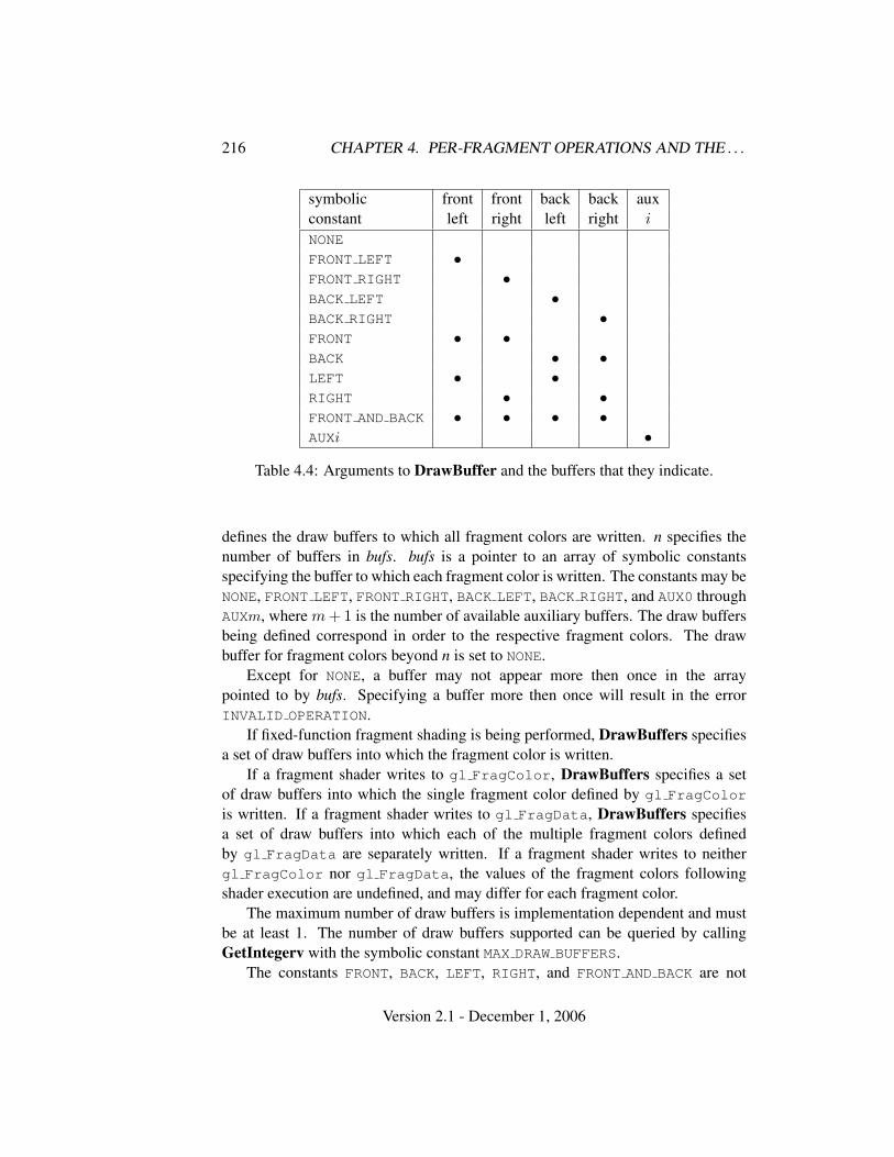
216 CHAPTER 4. PER-FRAGMENT OPERATIONS AND THE . . .
symbolic front front back back auxconstant left right left right i
NONE
FRONT LEFT •FRONT RIGHT •BACK LEFT •BACK RIGHT •FRONT • •BACK • •LEFT • •RIGHT • •FRONT AND BACK • • • •AUXi •
Table 4.4: Arguments to DrawBuffer and the buffers that they indicate.
defines the draw buffers to which all fragment colors are written. n specifies thenumber of buffers in bufs. bufs is a pointer to an array of symbolic constantsspecifying the buffer to which each fragment color is written. The constants may beNONE, FRONT LEFT, FRONT RIGHT, BACK LEFT, BACK RIGHT, and AUX0 throughAUXm, where m + 1 is the number of available auxiliary buffers. The draw buffersbeing defined correspond in order to the respective fragment colors. The drawbuffer for fragment colors beyond n is set to NONE.
Except for NONE, a buffer may not appear more then once in the arraypointed to by bufs. Specifying a buffer more then once will result in the errorINVALID OPERATION.
If fixed-function fragment shading is being performed, DrawBuffers specifiesa set of draw buffers into which the fragment color is written.
If a fragment shader writes to gl FragColor, DrawBuffers specifies a setof draw buffers into which the single fragment color defined by gl FragColor
is written. If a fragment shader writes to gl FragData, DrawBuffers specifiesa set of draw buffers into which each of the multiple fragment colors definedby gl FragData are separately written. If a fragment shader writes to neithergl FragColor nor gl FragData, the values of the fragment colors followingshader execution are undefined, and may differ for each fragment color.
The maximum number of draw buffers is implementation dependent and mustbe at least 1. The number of draw buffers supported can be queried by callingGetIntegerv with the symbolic constant MAX DRAW BUFFERS.
The constants FRONT, BACK, LEFT, RIGHT, and FRONT AND BACK are not
Version 2.1 - December 1, 2006
4.2. WHOLE FRAMEBUFFER OPERATIONS 217
valid in the bufs array passed to DrawBuffers, and will result in the errorINVALID OPERATION. This restriction is because these constants may themselvesrefer to multiple buffers, as shown in table 4.4.
If DrawBuffers is supplied with a constant (other than NONE) that doesnot indicate any of the color buffers allocated to the GL context, the errorINVALID OPERATION will be generated. If n is greater than the value ofMAX DRAW BUFFERS, the error INVALID VALUE will be generated.
Indicating a buffer or buffers using DrawBuffer or DrawBuffers causes sub-sequent pixel color value writes to affect the indicated buffers.
Specifying NONE as the draw buffer for an fragment color will inhibit that frag-ment color from being written to any buffer.
Monoscopic contexts include only left buffers, while stereoscopic contexts in-clude both left and right buffers. Likewise, single buffered contexts include onlyfront buffers, while double buffered contexts include both front and back buffers.The type of context is selected at GL initialization.
The state required to handle color buffer selection is an integer for each sup-ported fragment color. In the initial state, the draw buffer for fragment color zerois FRONT if there are no back buffers; otherwise it is BACK. The initial state of drawbuffers for fragment colors other then zero is NONE.
4.2.2 Fine Control of Buffer Updates
Four commands are used to mask the writing of bits to each of the logical frame-buffers after all per-fragment operations have been performed. The commands
void IndexMask( uint mask );void ColorMask( boolean r, boolean g, boolean b,
boolean a );
control the color buffer or buffers (depending on which buffers are currently indi-cated for writing). The least significant n bits of mask, where n is the number ofbits in a color index buffer, specify a mask. Where a 1 appears in this mask, thecorresponding bit in the color index buffer (or buffers) is written; where a 0 ap-pears, the bit is not written. This mask applies only in color index mode. In RGBAmode, ColorMask is used to mask the writing of R, G, B and A values to the colorbuffer or buffers. r, g, b, and a indicate whether R, G, B, or A values, respectively,are written or not (a value of TRUE means that the corresponding value is written).In the initial state, all bits (in color index mode) and all color values (in RGBAmode) are enabled for writing.
The depth buffer can be enabled or disabled for writing zw values using
Version 2.1 - December 1, 2006
218 CHAPTER 4. PER-FRAGMENT OPERATIONS AND THE . . .
void DepthMask( boolean mask );
If mask is non-zero, the depth buffer is enabled for writing; otherwise, it is disabled.In the initial state, the depth buffer is enabled for writing.
The commands
void StencilMask( uint mask );void StencilMaskSeparate( enum face, uint mask );
control the writing of particular bits into the stencil planes.The least significant s bits of mask comprise an integer mask (s is the number
of bits in the stencil buffer), just as for IndexMask. The face parameter of Stencil-MaskSeparate can be FRONT, BACK, or FRONT AND BACK and indicates whetherthe front or back stencil mask state is affected. StencilMask sets both front andback stencil mask state to identical values.
Fragments generated by front facing primitives use the front mask and frag-ments generated by back facing primitives use the back mask (see section 4.1.5).The clear operation always uses the front stencil write mask when clearing thestencil buffer.
The state required for the various masking operations is three integers and abit: an integer for color indices, an integer for the front and back stencil values,and a bit for depth values. A set of four bits is also required indicating which colorcomponents of an RGBA value should be written. In the initial state, the integermasks are all ones, as are the bits controlling depth value and RGBA componentwriting.
Fine Control of Multisample Buffer Updates
When the value of SAMPLE BUFFERS is one, ColorMask, DepthMask, and Sten-cilMask or StencilMaskSeparate control the modification of values in the multi-sample buffer. The color mask has no effect on modifications to the color buffers.If the color mask is entirely disabled, the color sample values must still be com-bined (as described above) and the result used to replace the color values of thebuffers enabled by DrawBuffer.
4.2.3 Clearing the Buffers
The GL provides a means for setting portions of every pixel in a particular bufferto the same value. The argument to
void Clear( bitfield buf );
Version 2.1 - December 1, 2006
4.2. WHOLE FRAMEBUFFER OPERATIONS 219
is the bitwise OR of a number of values indicating which buffers areto be cleared. The values are COLOR BUFFER BIT, DEPTH BUFFER BIT,STENCIL BUFFER BIT, and ACCUM BUFFER BIT, indicating the buffers currentlyenabled for color writing, the depth buffer, the stencil buffer, and the accumulationbuffer (see below), respectively. The value to which each buffer is cleared dependson the setting of the clear value for that buffer. If the mask is not a bitwise OR ofthe specified values, then the error INVALID VALUE is generated.
void ClearColor( clampf r, clampf g, clampf b,clampf a );
sets the clear value for the color buffers in RGBA mode. Each of the specifiedcomponents is clamped to [0, 1] and converted to fixed-point according to the rulesof section 2.14.9.
void ClearIndex( float index );
sets the clear color index. index is converted to a fixed-point value with unspecifiedprecision to the left of the binary point; the integer part of this value is then maskedwith 2m − 1, where m is the number of bits in a color index value stored in theframebuffer.
void ClearDepth( clampd d );
takes a floating-point value that is clamped to the range [0, 1] and converted tofixed-point according to the rules for a window z value given in section 2.11.1.Similarly,
void ClearStencil( int s );
takes a single integer argument that is the value to which to clear the stencil buffer.s is masked to the number of bitplanes in the stencil buffer.
void ClearAccum( float r, float g, float b, float a );
takes four floating-point arguments that are the values, in order, to which to set theR, G, B, and A values of the accumulation buffer (see the next section). Thesevalues are clamped to the range [−1, 1] when they are specified.
When Clear is called, the only per-fragment operations that are applied (ifenabled) are the pixel ownership test, the scissor test, and dithering. The maskingoperations described in the last section (4.2.2) are also effective. If a buffer is notpresent, then a Clear directed at that buffer has no effect.
Version 2.1 - December 1, 2006
220 CHAPTER 4. PER-FRAGMENT OPERATIONS AND THE . . .
The state required for clearing is a clear value for each of the color buffer, thedepth buffer, the stencil buffer, and the accumulation buffer. Initially, the RGBAcolor clear value is (0,0,0,0), the clear color index is 0, and the stencil buffer andaccumulation buffer clear values are all 0. The depth buffer clear value is initially1.0.
Clearing the Multisample Buffer
The color samples of the multisample buffer are cleared when one or more colorbuffers are cleared, as specified by the Clear mask bit COLOR BUFFER BIT andthe DrawBuffer mode. If the DrawBuffer mode is NONE, the color samples of themultisample buffer cannot be cleared.
If the Clear mask bits DEPTH BUFFER BIT or STENCIL BUFFER BIT are set,then the corresponding depth or stencil samples, respectively, are cleared.
4.2.4 The Accumulation Buffer
Each portion of a pixel in the accumulation buffer consists of four values: one foreach of R, G, B, and A. The accumulation buffer is controlled exclusively throughthe use of
void Accum( enum op, float value );
(except for clearing it). op is a symbolic constant indicating an accumulation bufferoperation, and value is a floating-point value to be used in that operation. Thepossible operations are ACCUM, LOAD, RETURN, MULT, and ADD.
When the scissor test is enabled (section 4.1.2), then only those pixels withinthe current scissor box are updated by any Accum operation; otherwise, all pixelsin the window are updated. The accumulation buffer operations apply identicallyto every affected pixel, so we describe the effect of each operation on an individ-ual pixel. Accumulation buffer values are taken to be signed values in the range[−1, 1]. Using ACCUM obtains R, G, B, and A components from the buffer currentlyselected for reading (section 4.3.2). Each component, considered as a fixed-pointvalue in [0, 1]. (see section 2.14.9), is converted to floating-point. Each result isthen multiplied by value. The results of this multiplication are then added to thecorresponding color component currently in the accumulation buffer, and the re-sulting color value replaces the current accumulation buffer color value.
The LOAD operation has the same effect as ACCUM, but the computed valuesreplace the corresponding accumulation buffer components rather than being addedto them.
Version 2.1 - December 1, 2006
4.3. DRAWING, READING, AND COPYING PIXELS 221
The RETURN operation takes each color value from the accumulation buffer,multiplies each of the R, G, B, and A components by value, and clamps the re-sults to the range [0, 1] The resulting color value is placed in the buffers currentlyenabled for color writing as if it were a fragment produced from rasterization, ex-cept that the only per-fragment operations that are applied (if enabled) are the pixelownership test, the scissor test (section 4.1.2), and dithering (section 4.1.9). Colormasking (section 4.2.2) is also applied.
The MULT operation multiplies each R, G, B, and A in the accumulation bufferby value and then returns the scaled color components to their corresponding ac-cumulation buffer locations. ADD is the same as MULT except that value is added toeach of the color components.
The color components operated on by Accum must be clamped only if theoperation is RETURN. In this case, a value sent to the enabled color buffers is firstclamped to [0, 1]. Otherwise, results are undefined if the result of an operation ona color component is out of the range [−1, 1].
If there is no accumulation buffer, or if the GL is in color index mode, Accumgenerates the error INVALID OPERATION.
No state (beyond the accumulation buffer itself) is required for accumulationbuffering.
4.3 Drawing, Reading, and Copying Pixels
Pixels may be written to and read from the framebuffer using the DrawPixels andReadPixels commands. CopyPixels can be used to copy a block of pixels fromone portion of the framebuffer to another.
4.3.1 Writing to the Stencil Buffer
The operation of DrawPixels was described in section 3.6.4, except if the formatargument was STENCIL INDEX. In this case, all operations described for Draw-Pixels take place, but window (x, y) coordinates, each with the correspondingstencil index, are produced in lieu of fragments. Each coordinate-stencil index pairis sent directly to the per-fragment operations, bypassing the texture, fog, and an-tialiasing application stages of rasterization. Each pair is then treated as a fragmentfor purposes of the pixel ownership and scissor tests; all other per-fragment opera-tions are bypassed. Finally, each stencil index is written to its indicated location inthe framebuffer, subject to the current front stencil mask (set with StencilMask orStencilMaskSeparate). If a depth component is present, and the setting of Depth-Mask is not FALSE, is also written to the framebuffer; the setting of DepthTest is
Version 2.1 - December 1, 2006
222 CHAPTER 4. PER-FRAGMENT OPERATIONS AND THE . . .
ignored.The error INVALID OPERATION results if there is no stencil buffer.
4.3.2 Reading Pixels
The method for reading pixels from the framebuffer and placing them in pixelpack buffer or client memory is diagrammed in figure 4.2. We describe the stagesof the pixel reading process in the order in which they occur.
Initially, zero is bound for the PIXEL PACK BUFFER, indicating that imageread and query commands such as ReadPixels return pixels results into clientmemory pointer parameters. However, if a non-zero buffer object is bound as thecurrent pixel pack buffer, then the pointer parameter is treated as an offset into thedesignated buffer object.
Pixels are read using
void ReadPixels( int x, int y, sizei width, sizei height,enum format, enum type, void *data );
The arguments after x and y to ReadPixels correspond to those of DrawPixels.The pixel storage modes that apply to ReadPixels and other commands that queryimages (see section 6.1) are summarized in table 4.5.
Obtaining Pixels from the Framebuffer
If the format is DEPTH COMPONENT, then values are obtained from the depth buffer.If there is no depth buffer, the error INVALID OPERATION occurs.
If there is a multisample buffer (the value of SAMPLE BUFFERS is one), thenvalues are obtained from the depth samples in this buffer. It is recommended thatthe depth value of the centermost sample be used, though implementations maychoose any function of the depth sample values at each pixel.
If the format is STENCIL INDEX, then values are taken from the stencil buffer;again, if there is no stencil buffer, the error INVALID OPERATION occurs.
If there is a multisample buffer, then values are obtained from the stencil sam-ples in this buffer. It is recommended that the stencil value of the centermost sam-ple be used, though implementations may choose any function of the stencil samplevalues at each pixel.
For all other formats, the buffer from which values are obtained is one of thecolor buffers; the selection of color buffer is controlled with ReadBuffer.
The command
void ReadBuffer( enum src );
Version 2.1 - December 1, 2006
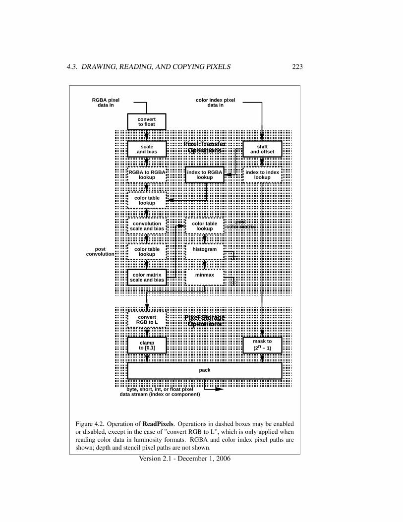
4.3. DRAWING, READING, AND COPYING PIXELS 223
postconvolution
convertto float
RGBA pixeldata in
color index pixeldata in
� � � � � � � � � � � � � � � � � � � � � � � � � � � � � � �� � � � � � � � � � � � � � � � � � � � � � � � � � � � � � �� � � � � � � � � � � � � � � � � � � � � � � � � � � � � � �� � � � � � � � � � � � � � � � � � � � � � � � � � � � � � �� � � � � � � � � � � � � � � � � � � � � � � � � � � � � � �� � � � � � � � � � � � � � � � � � � � � � � � � � � � � � �� � � � � � � � � � � � � � � � � � � � � � � � � � � � � � �� � � � � � � � � � � � � � � � � � � � � � � � � � � � � � �� � � � � � � � � � � � � � � � � � � � � � � � � � � � � � �� � � � � � � � � � � � � � � � � � � � � � � � � � � � � � �� � � � � � � � � � � � � � � � � � � � � � � � � � � � � � �� � � � � � � � � � � � � � � � � � � � � � � � � � � � � � �� � � � � � � � � � � � � � � � � � � � � � � � � � � � � � �� � � � � � � � � � � � � � � � � � � � � � � � � � � � � � �� � � � � � � � � � � � � � � � � � � � � � � � � � � � � � �� � � � � � � � � � � � � � � � � � � � � � � � � � � � � � �� � � � � � � � � � � � � � � � � � � � � � � � � � � � � � �� � � � � � � � � � � � � � � � � � � � � � � � � � � � � � �� � � � � � � � � � � � � � � � � � � � � � � � � � � � � � �� � � � � � � � � � � � � � � � � � � � � � � � � � � � � � �� � � � � � � � � � � � � � � � � � � � � � � � � � � � � � �� � � � � � � � � � � � � � � � � � � � � � � � � � � � � � �� � � � � � � � � � � � � � � � � � � � � � � � � � � � � � �� � � � � � � � � � � � � � � � � � � � � � � � � � � � � � �� � � � � � � � � � � � � � � � � � � � � � � � � � � � � � �� � � � � � � � � � � � � � � � � � � � � � � � � � � � � � �� � � � � � � � � � � � � � � � � � � � � � � � � � � � � � �� � � � � � � � � � � � � � � � � � � � � � � � � � � � � � �� � � � � � � � � � � � � � � � � � � � � � � � � � � � � � �
scaleand bias
Pixel TransferOperations
color table lookup
convolution scale a nd bias
histogram
minmax
color table lookup
RGBA to RGBA lookup
shiftand offset
index to index look up
index to RGBA looku p
color table lookup
color matrixscale and bias
postcolor matrix
� � � � � � � � � � � � � � � � � � � � � � � � � � � � � � �� � � � � � � � � � � � � � � � � � � � � � � � � � � � � � �� � � � � � � � � � � � � � � � � � � � � � � � � � � � � � �� � � � � � � � � � � � � � � � � � � � � � � � � � � � � � �� � � � � � � � � � � � � � � � � � � � � � � � � � � � � � �� � � � � � � � � � � � � � � � � � � � � � � � � � � � � � �� � � � � � � � � � � � � � � � � � � � � � � � � � � � � � �� � � � � � � � � � � � � � � � � � � � � � � � � � � � � � �� � � � � � � � � � � � � � � � � � � � � � � � � � � � � � �� � � � � � � � � � � � � � � � � � � � � � � � � � � � � � �� � � � � � � � � � � � � � � � � � � � � � � � � � � � � � �� � � � � � � � � � � � � � � � � � � � � � � � � � � � � � �� � � � � � � � � � � � � � � � � � � � � � � � � � � � � � �� � � � � � � � � � � � � � � � � � � � � � � � � � � � � � �
pack
convertRGB to L
clampto [0,1]
mask to(2n − 1)
byte, short, int, o r float pixeldata stream (index or component)
Pixel StorageOperations
Figure 4.2. Operation of ReadPixels. Operations in dashed boxes may be enabledor disabled, except in the case of ”convert RGB to L”, which is only applied whenreading color data in luminosity formats. RGBA and color index pixel paths areshown; depth and stencil pixel paths are not shown.
Version 2.1 - December 1, 2006
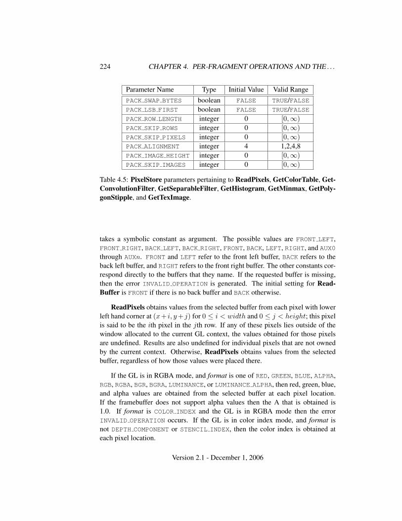
224 CHAPTER 4. PER-FRAGMENT OPERATIONS AND THE . . .
Parameter Name Type Initial Value Valid RangePACK SWAP BYTES boolean FALSE TRUE/FALSEPACK LSB FIRST boolean FALSE TRUE/FALSEPACK ROW LENGTH integer 0 [0,∞)PACK SKIP ROWS integer 0 [0,∞)PACK SKIP PIXELS integer 0 [0,∞)PACK ALIGNMENT integer 4 1,2,4,8PACK IMAGE HEIGHT integer 0 [0,∞)PACK SKIP IMAGES integer 0 [0,∞)
Table 4.5: PixelStore parameters pertaining to ReadPixels, GetColorTable, Get-ConvolutionFilter, GetSeparableFilter, GetHistogram, GetMinmax, GetPoly-gonStipple, and GetTexImage.
takes a symbolic constant as argument. The possible values are FRONT LEFT,FRONT RIGHT, BACK LEFT, BACK RIGHT, FRONT, BACK, LEFT, RIGHT, and AUX0through AUXn. FRONT and LEFT refer to the front left buffer, BACK refers to theback left buffer, and RIGHT refers to the front right buffer. The other constants cor-respond directly to the buffers that they name. If the requested buffer is missing,then the error INVALID OPERATION is generated. The initial setting for Read-Buffer is FRONT if there is no back buffer and BACK otherwise.
ReadPixels obtains values from the selected buffer from each pixel with lowerleft hand corner at (x+ i, y + j) for 0 ≤ i < width and 0 ≤ j < height; this pixelis said to be the ith pixel in the jth row. If any of these pixels lies outside of thewindow allocated to the current GL context, the values obtained for those pixelsare undefined. Results are also undefined for individual pixels that are not ownedby the current context. Otherwise, ReadPixels obtains values from the selectedbuffer, regardless of how those values were placed there.
If the GL is in RGBA mode, and format is one of RED, GREEN, BLUE, ALPHA,RGB, RGBA, BGR, BGRA, LUMINANCE, or LUMINANCE ALPHA, then red, green, blue,and alpha values are obtained from the selected buffer at each pixel location.If the framebuffer does not support alpha values then the A that is obtained is1.0. If format is COLOR INDEX and the GL is in RGBA mode then the errorINVALID OPERATION occurs. If the GL is in color index mode, and format isnot DEPTH COMPONENT or STENCIL INDEX, then the color index is obtained ateach pixel location.
Version 2.1 - December 1, 2006
4.3. DRAWING, READING, AND COPYING PIXELS 225
Conversion of RGBA values
This step applies only if the GL is in RGBA mode, and then only if format isneither STENCIL INDEX nor DEPTH COMPONENT. The R, G, B, and A values forma group of elements. Each element is taken to be a fixed-point value in [0, 1] withm bits, where m is the number of bits in the corresponding color component of theselected buffer (see section 2.14.9).
Conversion of Depth values
This step applies only if format is DEPTH COMPONENT. An element is taken to be afixed-point value in [0,1] with m bits, where m is the number of bits in the depthbuffer (see section 2.11.1).
Pixel Transfer Operations
This step is actually the sequence of steps that was described separately in sec-tion 3.6.5. After the processing described in that section is completed, groups areprocessed as described in the following sections.
Conversion to L
This step applies only to RGBA component groups, and only if the format is eitherLUMINANCE or LUMINANCE ALPHA. A value L is computed as
L = R + G + B
where R, G, and B are the values of the R, G, and B components. The singlecomputed L component replaces the R, G, and B components in the group.
Final Conversion
For an index, if the type is not FLOAT, final conversion consists of masking theindex with the value given in table 4.6; if the type is FLOAT, then the integer indexis converted to a GL float data value.
For an RGBA color, each component is first clamped to [0, 1]. Then theappropriate conversion formula from table 4.7 is applied to the component.
Placement in Pixel Pack Buffer or Client Memory
If a pixel pack buffer is bound (as indicated by a non-zero value ofPIXEL PACK BUFFER BINDING), data is an offset into the pixel pack buffer and
Version 2.1 - December 1, 2006
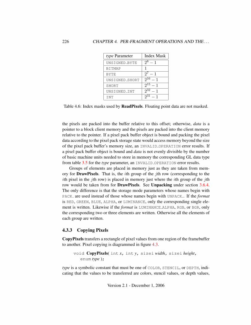
226 CHAPTER 4. PER-FRAGMENT OPERATIONS AND THE . . .
type Parameter Index MaskUNSIGNED BYTE 28 − 1BITMAP 1BYTE 27 − 1UNSIGNED SHORT 216 − 1SHORT 215 − 1UNSIGNED INT 232 − 1INT 231 − 1
Table 4.6: Index masks used by ReadPixels. Floating point data are not masked.
the pixels are packed into the buffer relative to this offset; otherwise, data is apointer to a block client memory and the pixels are packed into the client memoryrelative to the pointer. If a pixel pack buffer object is bound and packing the pixeldata according to the pixel pack storage state would access memory beyond the sizeof the pixel pack buffer’s memory size, an INVALID OPERATION error results. Ifa pixel pack buffer object is bound and data is not evenly divisible by the numberof basic machine units needed to store in memory the corresponding GL data typefrom table 3.5 for the type parameter, an INVALID OPERATION error results.
Groups of elements are placed in memory just as they are taken from mem-ory for DrawPixels. That is, the ith group of the jth row (corresponding to theith pixel in the jth row) is placed in memory just where the ith group of the jthrow would be taken from for DrawPixels. See Unpacking under section 3.6.4.The only difference is that the storage mode parameters whose names begin withPACK are used instead of those whose names begin with UNPACK . If the formatis RED, GREEN, BLUE, ALPHA, or LUMINANCE, only the corresponding single ele-ment is written. Likewise if the format is LUMINANCE ALPHA, RGB, or BGR, onlythe corresponding two or three elements are written. Otherwise all the elements ofeach group are written.
4.3.3 Copying Pixels
CopyPixels transfers a rectangle of pixel values from one region of the framebufferto another. Pixel copying is diagrammed in figure 4.3.
void CopyPixels( int x, int y, sizei width, sizei height,enum type );
type is a symbolic constant that must be one of COLOR, STENCIL, or DEPTH, indi-cating that the values to be transferred are colors, stencil values, or depth values,
Version 2.1 - December 1, 2006
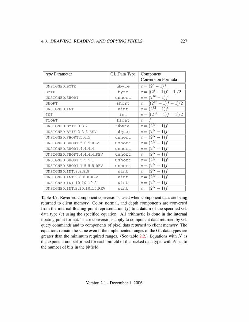
4.3. DRAWING, READING, AND COPYING PIXELS 227
type Parameter GL Data Type ComponentConversion Formula
UNSIGNED BYTE ubyte c = (28 − 1)fBYTE byte c = [(28 − 1)f − 1]/2UNSIGNED SHORT ushort c = (216 − 1)fSHORT short c = [(216 − 1)f − 1]/2UNSIGNED INT uint c = (232 − 1)fINT int c = [(232 − 1)f − 1]/2FLOAT float c = f
UNSIGNED BYTE 3 3 2 ubyte c = (2N − 1)fUNSIGNED BYTE 2 3 3 REV ubyte c = (2N − 1)fUNSIGNED SHORT 5 6 5 ushort c = (2N − 1)fUNSIGNED SHORT 5 6 5 REV ushort c = (2N − 1)fUNSIGNED SHORT 4 4 4 4 ushort c = (2N − 1)fUNSIGNED SHORT 4 4 4 4 REV ushort c = (2N − 1)fUNSIGNED SHORT 5 5 5 1 ushort c = (2N − 1)fUNSIGNED SHORT 1 5 5 5 REV ushort c = (2N − 1)fUNSIGNED INT 8 8 8 8 uint c = (2N − 1)fUNSIGNED INT 8 8 8 8 REV uint c = (2N − 1)fUNSIGNED INT 10 10 10 2 uint c = (2N − 1)fUNSIGNED INT 2 10 10 10 REV uint c = (2N − 1)f
Table 4.7: Reversed component conversions, used when component data are beingreturned to client memory. Color, normal, and depth components are convertedfrom the internal floating-point representation (f ) to a datum of the specified GLdata type (c) using the specified equation. All arithmetic is done in the internalfloating point format. These conversions apply to component data returned by GLquery commands and to components of pixel data returned to client memory. Theequations remain the same even if the implemented ranges of the GL data types aregreater than the minimum required ranges. (See table 2.2.) Equations with N asthe exponent are performed for each bitfield of the packed data type, with N set tothe number of bits in the bitfield.
Version 2.1 - December 1, 2006
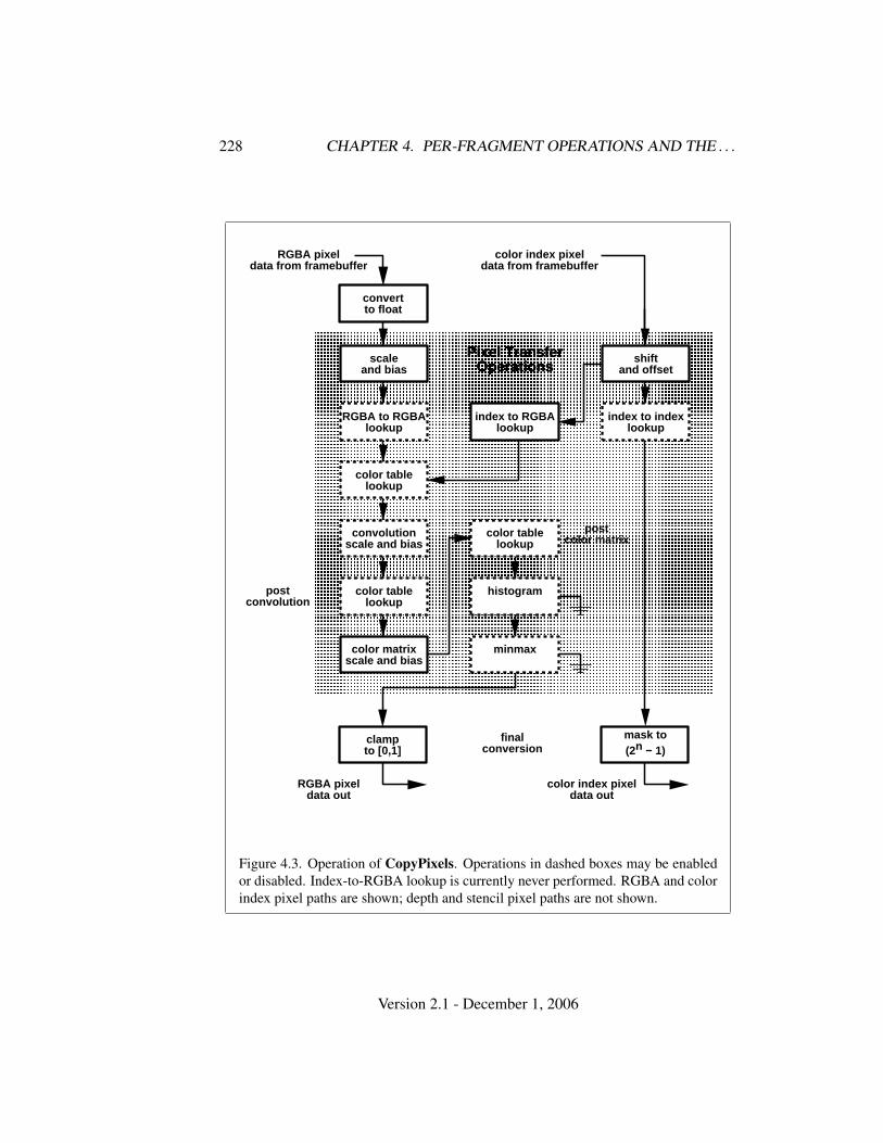
228 CHAPTER 4. PER-FRAGMENT OPERATIONS AND THE . . .
postconvolution
� � � � � � � � � � � � � � � � � � � � � � � � � � � � � � �� � � � � � � � � � � � � � � � � � � � � � � � � � � � � � �� � � � � � � � � � � � � � � � � � � � � � � � � � � � � � �� � � � � � � � � � � � � � � � � � � � � � � � � � � � � � �� � � � � � � � � � � � � � � � � � � � � � � � � � � � � � �� � � � � � � � � � � � � � � � � � � � � � � � � � � � � � �� � � � � � � � � � � � � � � � � � � � � � � � � � � � � � �� � � � � � � � � � � � � � � � � � � � � � � � � � � � � � �� � � � � � � � � � � � � � � � � � � � � � � � � � � � � � �� � � � � � � � � � � � � � � � � � � � � � � � � � � � � � �� � � � � � � � � � � � � � � � � � � � � � � � � � � � � � �� � � � � � � � � � � � � � � � � � � � � � � � � � � � � � �� � � � � � � � � � � � � � � � � � � � � � � � � � � � � � �� � � � � � � � � � � � � � � � � � � � � � � � � � � � � � �� � � � � � � � � � � � � � � � � � � � � � � � � � � � � � �� � � � � � � � � � � � � � � � � � � � � � � � � � � � � � �� � � � � � � � � � � � � � � � � � � � � � � � � � � � � � �� � � � � � � � � � � � � � � � � � � � � � � � � � � � � � �� � � � � � � � � � � � � � � � � � � � � � � � � � � � � � �� � � � � � � � � � � � � � � � � � � � � � � � � � � � � � �� � � � � � � � � � � � � � � � � � � � � � � � � � � � � � �� � � � � � � � � � � � � � � � � � � � � � � � � � � � � � �� � � � � � � � � � � � � � � � � � � � � � � � � � � � � � �� � � � � � � � � � � � � � � � � � � � � � � � � � � � � � �� � � � � � � � � � � � � � � � � � � � � � � � � � � � � � �� � � � � � � � � � � � � � � � � � � � � � � � � � � � � � �� � � � � � � � � � � � � � � � � � � � � � � � � � � � � � �� � � � � � � � � � � � � � � � � � � � � � � � � � � � � � �
scaleand bias
Pixel TransferOperations
color table lookup
convolution scale a nd bias
histogram
minmax
color table lookup
RGBA to RGBA lookup
shiftand offset
index to index look up
index to RGBA looku p
color table lookup
color matrixscale and bias
postcolor matrix
convertto float
RGBA pixeldata from framebuff er
color index pixeldata from framebuff er
color index pixeldata out
RGBA pixeldata out
clampto [0,1]
mask to(2n − 1)
finalconversion
Figure 4.3. Operation of CopyPixels. Operations in dashed boxes may be enabledor disabled. Index-to-RGBA lookup is currently never performed. RGBA and colorindex pixel paths are shown; depth and stencil pixel paths are not shown.
Version 2.1 - December 1, 2006
4.3. DRAWING, READING, AND COPYING PIXELS 229
respectively. The first four arguments have the same interpretation as the corre-sponding arguments to ReadPixels.
Values are obtained from the framebuffer, converted (if appropriate), then sub-jected to the pixel transfer operations described in section 3.6.5, just as if Read-Pixels were called with the corresponding arguments. If the type is STENCIL
or DEPTH, then it is as if the format for ReadPixels were STENCIL INDEX orDEPTH COMPONENT, respectively. If the type is COLOR, then if the GL is in RGBAmode, it is as if the format were RGBA, while if the GL is in color index mode, it isas if the format were COLOR INDEX.
The groups of elements so obtained are then written to the framebuffer just asif DrawPixels had been given width and height, beginning with final conversionof elements. The effective format is the same as that already described.
4.3.4 Pixel Draw/Read State
The state required for pixel operations consists of the parameters that are set withPixelStore, PixelTransfer, and PixelMap. This state has been summarized intables 3.1, 3.2, and 3.3. The current setting of ReadBuffer, an integer, is alsorequired, along with the current raster position (section 2.13). State set with Pixel-Store is GL client state.
Version 2.1 - December 1, 2006

Chapter 5
Special Functions
This chapter describes additional GL functionality that does not fit easily into anyof the preceding chapters. This functionality consists of evaluators (used to modelcurves and surfaces), selection (used to locate rendered primitives on the screen),feedback (which returns GL results before rasterization), display lists (used to des-ignate a group of GL commands for later execution by the GL), flushing and fin-ishing (used to synchronize the GL command stream), and hints.
5.1 Evaluators
Evaluators provide a means to use a polynomial or rational polynomial mappingto produce vertex, normal, and texture coordinates, and colors. The values so pro-duced are sent on to further stages of the GL as if they had been provided directlyby the client. Transformations, lighting, primitive assembly, rasterization, and per-pixel operations are not affected by the use of evaluators.
Consider the Rk-valued polynomial p(u) defined by
p(u) =n∑
i=0
Bni (u)Ri (5.1)
with Ri ∈ Rk and
Bni (u) =
(n
i
)ui(1− u)n−i,
the ith Bernstein polynomial of degree n (recall that 00 ≡ 1 and(n0
)≡ 1). Each
Ri is a control point. The relevant command is
void Map1{fd}( enum target, T u1, T u2, int stride,int order, T points );
230
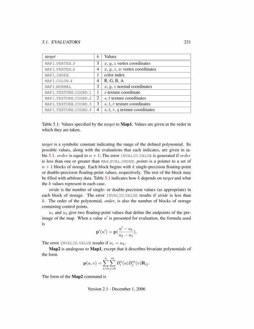
5.1. EVALUATORS 231
target k ValuesMAP1 VERTEX 3 3 x, y, z vertex coordinatesMAP1 VERTEX 4 4 x, y, z, w vertex coordinatesMAP1 INDEX 1 color indexMAP1 COLOR 4 4 R, G, B, AMAP1 NORMAL 3 x, y, z normal coordinatesMAP1 TEXTURE COORD 1 1 s texture coordinateMAP1 TEXTURE COORD 2 2 s, t texture coordinatesMAP1 TEXTURE COORD 3 3 s, t, r texture coordinatesMAP1 TEXTURE COORD 4 4 s, t, r, q texture coordinates
Table 5.1: Values specified by the target to Map1. Values are given in the order inwhich they are taken.
target is a symbolic constant indicating the range of the defined polynomial. Itspossible values, along with the evaluations that each indicates, are given in ta-ble 5.1. order is equal to n + 1; The error INVALID VALUE is generated if orderis less than one or greater than MAX EVAL ORDER. points is a pointer to a set ofn + 1 blocks of storage. Each block begins with k single-precision floating-pointor double-precision floating-point values, respectively. The rest of the block maybe filled with arbitrary data. Table 5.1 indicates how k depends on target and whatthe k values represent in each case.
stride is the number of single- or double-precision values (as appropriate) ineach block of storage. The error INVALID VALUE results if stride is less thank. The order of the polynomial, order, is also the number of blocks of storagecontaining control points.
u1 and u2 give two floating-point values that define the endpoints of the pre-image of the map. When a value u′ is presented for evaluation, the formula usedis
p′(u′) = p(u′ − u1
u2 − u1).
The error INVALID VALUE results if u1 = u2.Map2 is analogous to Map1, except that it describes bivariate polynomials of
the form
p(u, v) =n∑
i=0
m∑j=0
Bni (u)Bm
j (v)Rij .
The form of the Map2 command is
Version 2.1 - December 1, 2006
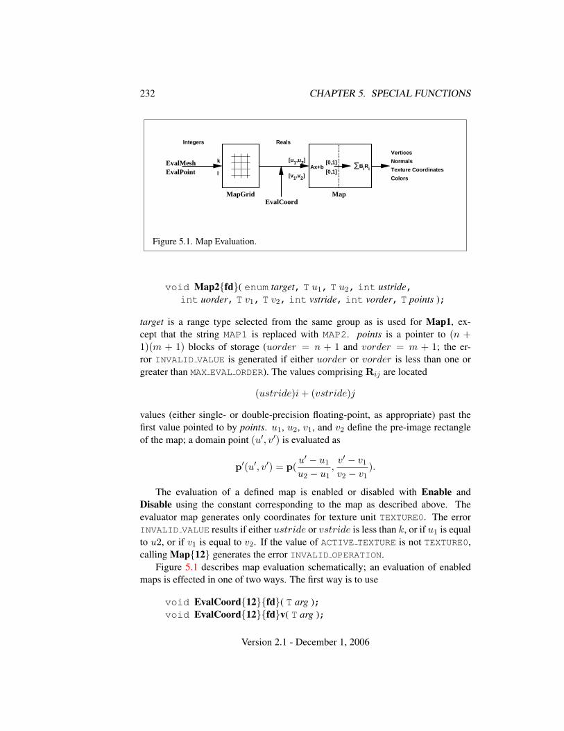
232 CHAPTER 5. SPECIAL FUNCTIONS
EvalMeshEvalPoint
MapGrid MapEvalCoord
k
l
[u1,u2]
[v1,v2]
[0,1]
[0,1]ΣBiRiAx+b
Vertices
Normals
Texture Coordinates
Colors
Integers Reals
Figure 5.1. Map Evaluation.
void Map2{fd}( enum target, T u1, T u2, int ustride,int uorder, T v1, T v2, int vstride, int vorder, T points );
target is a range type selected from the same group as is used for Map1, ex-cept that the string MAP1 is replaced with MAP2. points is a pointer to (n +1)(m + 1) blocks of storage (uorder = n + 1 and vorder = m + 1; the er-ror INVALID VALUE is generated if either uorder or vorder is less than one orgreater than MAX EVAL ORDER). The values comprising Rij are located
(ustride)i + (vstride)j
values (either single- or double-precision floating-point, as appropriate) past thefirst value pointed to by points. u1, u2, v1, and v2 define the pre-image rectangleof the map; a domain point (u′, v′) is evaluated as
p′(u′, v′) = p(u′ − u1
u2 − u1,v′ − v1
v2 − v1).
The evaluation of a defined map is enabled or disabled with Enable andDisable using the constant corresponding to the map as described above. Theevaluator map generates only coordinates for texture unit TEXTURE0. The errorINVALID VALUE results if either ustride or vstride is less than k, or if u1 is equalto u2, or if v1 is equal to v2. If the value of ACTIVE TEXTURE is not TEXTURE0,calling Map{12} generates the error INVALID OPERATION.
Figure 5.1 describes map evaluation schematically; an evaluation of enabledmaps is effected in one of two ways. The first way is to use
void EvalCoord{12}{fd}( T arg );void EvalCoord{12}{fd}v( T arg );
Version 2.1 - December 1, 2006
5.1. EVALUATORS 233
EvalCoord1 causes evaluation of the enabled one-dimensional maps. The argu-ment is the value (or a pointer to the value) that is the domain coordinate, u′. Eval-Coord2 causes evaluation of the enabled two-dimensional maps. The two valuesspecify the two domain coordinates, u′ and v′, in that order.
When one of the EvalCoord commands is issued, all currently enabled mapsof the indicated dimension are evaluated. Then, for each enabled map, it is as if acorresponding GL command were issued with the resulting coordinates, with oneimportant difference. The difference is that when an evaluation is performed, theGL uses evaluated values instead of current values for those evaluations that areenabled (otherwise, the current values are used). The order of the effective com-mands is immaterial, except that Vertex (for vertex coordinate evaluation) must beissued last. Use of evaluators has no effect on the current color, normal, or texturecoordinates. If ColorMaterial is enabled, evaluated color values affect the resultof the lighting equation as if the current color was being modified, but no changeis made to the tracking lighting parameters or to the current color.
No command is effectively issued if the corresponding map (of the indicateddimension) is not enabled. If more than one evaluation is enabled for a particu-lar dimension (e.g. MAP1 TEXTURE COORD 1 and MAP1 TEXTURE COORD 2), thenonly the result of the evaluation of the map with the highest number of coordinatesis used.
Finally, if either MAP2 VERTEX 3 or MAP2 VERTEX 4 is enabled, then the nor-mal to the surface is computed. Analytic computation, which sometimes yieldsnormals of length zero, is one method which may be used. If automatic normalgeneration is enabled, then this computed normal is used as the normal associatedwith a generated vertex. Automatic normal generation is controlled with Enableand Disable with the symbolic constant AUTO NORMAL. If automatic normal gener-ation is disabled, then a corresponding normal map, if enabled, is used to producea normal. If neither automatic normal generation nor a normal map are enabled,then no normal is sent with a vertex resulting from an evaluation (the effect is thatthe current normal is used).
For MAP VERTEX 3, let q = p. For MAP VERTEX 4, let q = (x/w, y/w, z/w),where (x, y, z, w) = p. Then let
m =∂q∂u× ∂q
∂v.
Then the generated analytic normal, n, is given by n = m if a vertex shader isactive, or else by n = m
‖m‖ .The second way to carry out evaluations is to use a set of commands that pro-
vide for efficient specification of a series of evenly spaced values to be mapped.This method proceeds in two steps. The first step is to define a grid in the domain.
Version 2.1 - December 1, 2006
234 CHAPTER 5. SPECIAL FUNCTIONS
This is done using
void MapGrid1{fd}( int n, T u′1, T u′2 );
for a one-dimensional map or
void MapGrid2{fd}( int nu, T u′1, T u′2, int nv, T v′1,T v′2 );
for a two-dimensional map. In the case of MapGrid1 u′1 and u′2 describe aninterval, while n describes the number of partitions of the interval. The errorINVALID VALUE results if n ≤ 0. For MapGrid2, (u′1, v
′1) specifies one two-
dimensional point and (u′2, v′2) specifies another. nu gives the number of partitions
between u′1 and u′2, and nv gives the number of partitions between v′1 and v′2. Ifeither nu ≤ 0 or nv ≤ 0, then the error INVALID VALUE occurs.
Once a grid is defined, an evaluation on a rectangular subset of that grid maybe carried out by calling
void EvalMesh1( enum mode, int p1, int p2 );
mode is either POINT or LINE. The effect is the same as performing the followingcode fragment, with ∆u′ = (u′2 − u′1)/n:
Begin(type);for i = p1 to p2 step 1.0
EvalCoord1(i * ∆u′ + u′1);End();
where EvalCoord1f or EvalCoord1d is substituted for EvalCoord1 as appro-priate. If mode is POINT, then type is POINTS; if mode is LINE, then type isLINE STRIP. The one requirement is that if either i = 0 or i = n, then the valuecomputed from i ∗∆u′ + u′1 is precisely u′1 or u′2, respectively.
The corresponding commands for two-dimensional maps are
void EvalMesh2( enum mode, int p1, int p2, int q1,int q2 );
mode must be FILL, LINE, or POINT. When mode is FILL, then these commandsare equivalent to the following, with ∆u′ = (u′2−u′1)/n and ∆v′ = (v′2− v′1)/m:
Version 2.1 - December 1, 2006
5.1. EVALUATORS 235
for i = q1 to q2 − 1 step 1.0Begin(QUAD STRIP);
for j = p1 to p2 step 1.0EvalCoord2(j * ∆u′ + u′1 , i * ∆v′ + v′1);EvalCoord2(j * ∆u′ + u′1 , (i + 1) * ∆v′ + v′1);
End();
If mode is LINE, then a call to EvalMesh2 is equivalent to
for i = q1 to q2 step 1.0Begin(LINE STRIP);for j = p1 to p2 step 1.0
EvalCoord2(j * ∆u′ + u′1 , i * ∆v′ + v′1);End();;
for i = p1 to p2 step 1.0Begin(LINE STRIP);for j = q1 to q2 step 1.0
EvalCoord2(i * ∆u′ + u′1 , j * ∆v′ + v′1);End();
If mode is POINT, then a call to EvalMesh2 is equivalent to
Begin(POINTS);for i = q1 to q2 step 1.0
for j = p1 to p2 step 1.0EvalCoord2(j * ∆u′ + u′1 , i * ∆v′ + v′1);
End();
Again, in all three cases, there is the requirement that 0∗∆u′+u′1 = u′1, n∗∆u′+u′1 = u′2, 0 ∗∆v′ + v′1 = v′1, and m ∗∆v′ + v′1 = v′2.
An evaluation of a single point on the grid may also be carried out:
void EvalPoint1( int p );
Calling it is equivalent to the command
EvalCoord1(p * ∆u′ + u′1);
with ∆u′ and u′1 defined as above.
void EvalPoint2( int p, int q );
is equivalent to the command
Version 2.1 - December 1, 2006
236 CHAPTER 5. SPECIAL FUNCTIONS
EvalCoord2(p * ∆u′ + u′1 , q * ∆v′ + v′1);
The state required for evaluators potentially consists of 9 one-dimensional mapspecifications and 9 two-dimensional map specifications, as well as correspondingflags for each specification indicating which are enabled. Each map specificationconsists of one or two orders, an appropriately sized array of control points, and aset of two values (for a one-dimensional map) or four values (for a two-dimensionalmap) to describe the domain. The maximum possible order, for either u or v, isimplementation dependent (one maximum applies to both u and v), but must be atleast 8. Each control point consists of between one and four floating-point values(depending on the type of the map). Initially, all maps have order 1 (making themconstant maps). All vertex coordinate maps produce the coordinates (0, 0, 0, 1)(or the appropriate subset); all normal coordinate maps produce (0, 0, 1); RGBAmaps produce (1, 1, 1, 1); color index maps produce 1.0; and texture coordinatemaps produce (0, 0, 0, 1). In the initial state, all maps are disabled. A flag indi-cates whether or not automatic normal generation is enabled for two-dimensionalmaps. In the initial state, automatic normal generation is disabled. Also requiredare two floating-point values and an integer number of grid divisions for the one-dimensional grid specification and four floating-point values and two integer griddivisions for the two-dimensional grid specification. In the initial state, the boundsof the domain interval for 1-D is 0 and 1.0, respectively; for 2-D, they are (0, 0)and (1.0, 1.0), respectively. The number of grid divisions is 1 for 1-D and 1 inboth directions for 2-D. If any evaluation command is issued when no vertex mapis enabled for the map dimension being evaluated, nothing happens.
5.2 Selection
Selection is used to determine which primitives are drawn into some region of awindow. The region is defined by the current model-view and perspective matrices.
Selection works by returning an array of integer-valued names. This arrayrepresents the current contents of the name stack. This stack is controlled with thecommands
void InitNames( void );void PopName( void );void PushName( uint name );void LoadName( uint name );
InitNames empties (clears) the name stack. PopName pops one name off the topof the name stack. PushName causes name to be pushed onto the name stack.
Version 2.1 - December 1, 2006
5.2. SELECTION 237
LoadName replaces the value on the top of the stack with name. Loading a nameonto an empty stack generates the error INVALID OPERATION. Popping a name offof an empty stack generates STACK UNDERFLOW; pushing a name onto a full stackgenerates STACK OVERFLOW. The maximum allowable depth of the name stack isimplementation dependent but must be at least 64.
In selection mode, framebuffer updates as described in chapter 4 are not per-formed. The GL is placed in selection mode with
int RenderMode( enum mode );
mode is a symbolic constant: one of RENDER, SELECT, or FEEDBACK. RENDER isthe default, corresponding to rendering as described until now. SELECT specifiesselection mode, and FEEDBACK specifies feedback mode (described below). Useof any of the name stack manipulation commands while the GL is not in selectionmode has no effect.
Selection is controlled using
void SelectBuffer( sizei n, uint *buffer );
buffer is a pointer to an array of unsigned integers (called the selection array) to bepotentially filled with names, and n is an integer indicating the maximum numberof values that can be stored in that array. Placing the GL in selection mode beforeSelectBuffer has been called results in an error of INVALID OPERATION as doescalling SelectBuffer while in selection mode.
In selection mode, if a point, line, polygon, or the valid coordinates producedby a RasterPos command intersects the clip volume (section 2.12) then this prim-itive (or RasterPos command) causes a selection hit. WindowPos commands al-ways generate a selection hit, since the resulting raster position is always valid.In the case of polygons, no hit occurs if the polygon would have been culled, butselection is based on the polygon itself, regardless of the setting of PolygonMode.When in selection mode, whenever a name stack manipulation command is exe-cuted or RenderMode is called and there has been a hit since the last time the stackwas manipulated or RenderMode was called, then a hit record is written into theselection array.
A hit record consists of the following items in order: a non-negative integergiving the number of elements on the name stack at the time of the hit, a minimumdepth value, a maximum depth value, and the name stack with the bottommost el-ement first. The minimum and maximum depth values are the minimum and max-imum taken over all the window coordinate z values of each (post-clipping) vertexof each primitive that intersects the clipping volume since the last hit record was
Version 2.1 - December 1, 2006
238 CHAPTER 5. SPECIAL FUNCTIONS
written. The minimum and maximum (each of which lies in the range [0, 1]) areeach multiplied by 232−1 and rounded to the nearest unsigned integer to obtain thevalues that are placed in the hit record. No depth offset arithmetic (section 3.5.5)is performed on these values.
Hit records are placed in the selection array by maintaining a pointer into thatarray. When selection mode is entered, the pointer is initialized to the beginningof the array. Each time a hit record is copied, the pointer is updated to point atthe array element after the one into which the topmost element of the name stackwas stored. If copying the hit record into the selection array would cause the totalnumber of values to exceed n, then as much of the record as fits in the array iswritten and an overflow flag is set.
Selection mode is exited by calling RenderMode with an argument value otherthan SELECT. When called while in selection mode, RenderMode returns thenumber of hit records copied into the selection array and resets the SelectBufferpointer to its last specified value. Values are not guaranteed to be written into theselection array until RenderMode is called. If the selection array overflow flagwas set, then RenderMode returns −1 and clears the overflow flag. The namestack is cleared and the stack pointer reset whenever RenderMode is called.
The state required for selection consists of the address of the selection arrayand its maximum size, the name stack and its associated pointer, a minimum andmaximum depth value, and several flags. One flag indicates the current Render-Mode value. In the initial state, the GL is in the RENDER mode. Another flag isused to indicate whether or not a hit has occurred since the last name stack ma-nipulation. This flag is reset upon entering selection mode and whenever a namestack manipulation takes place. One final flag is required to indicate whether themaximum number of copied names would have been exceeded. This flag is resetupon entering selection mode. This flag, the address of the selection array, and itsmaximum size are GL client state.
5.3 Feedback
The GL is placed in feedback mode by calling RenderMode with FEEDBACK.When in feedback mode, framebuffer updates as described in chapter 4 are notperformed. Instead, information about primitives that would have otherwise beenrasterized is returned to the application via the feedback buffer.
Feedback is controlled using
void FeedbackBuffer( sizei n, enum type, float *buffer );
Version 2.1 - December 1, 2006
5.3. FEEDBACK 239
buffer is a pointer to an array of floating-point values into which feedback informa-tion will be placed, and n is a number indicating the maximum number of valuesthat can be written to that array. type is a symbolic constant describing the informa-tion to be fed back for each vertex (see figure 5.2). The error INVALID OPERATION
results if the GL is placed in feedback mode before a call to FeedbackBuffer hasbeen made, or if a call to FeedbackBuffer is made while in feedback mode.
While in feedback mode, each primitive that would be rasterized (or bitmapor call to DrawPixels or CopyPixels, if the raster position is valid) generates ablock of values that get copied into the feedback array. If doing so would causethe number of entries to exceed the maximum, the block is partially written so asto fill the array (if there is any room left at all). The first block of values gener-ated after the GL enters feedback mode is placed at the beginning of the feedbackarray, with subsequent blocks following. Each block begins with a code indicat-ing the primitive type, followed by values that describe the primitive’s vertices andassociated data. Entries are also written for bitmaps and pixel rectangles. Feed-back occurs after polygon culling (section 3.5.1) and PolygonMode interpretationof polygons (section 3.5.4) has taken place. It may also occur after polygons withmore than three edges are broken up into triangles (if the GL implementation ren-ders polygons by performing this decomposition). x, y, and z coordinates returnedby feedback are window coordinates; if w is returned, it is in clip coordinates. Nodepth offset arithmetic (section 3.5.5) is performed on the z values. In the caseof bitmaps and pixel rectangles, the coordinates returned are those of the currentraster position.
The texture coordinates and colors returned are those resulting from the clip-ping operations described in section 2.14.8. Only coordinates for texture unitTEXTURE0 are returned even for implementations which support multiple textureunits. The colors returned are the primary colors.
The ordering rules for GL command interpretation also apply in feedbackmode. Each command must be fully interpreted and its effects on both GL stateand the values to be written to the feedback buffer completed before a subsequentcommand may be executed.
Feedback mode is exited by calling RenderMode with an argument value otherthan FEEDBACK. When called while in feedback mode, RenderMode returns thenumber of values placed in the feedback array and resets the feedback array pointerto be buffer. The return value never exceeds the maximum number of values passedto FeedbackBuffer.
If writing a value to the feedback buffer would cause more values to be writtenthan the specified maximum number of values, then the value is not written and anoverflow flag is set. In this case, RenderMode returns −1 when it is called, afterwhich the overflow flag is reset. While in feedback mode, values are not guaranteed
Version 2.1 - December 1, 2006
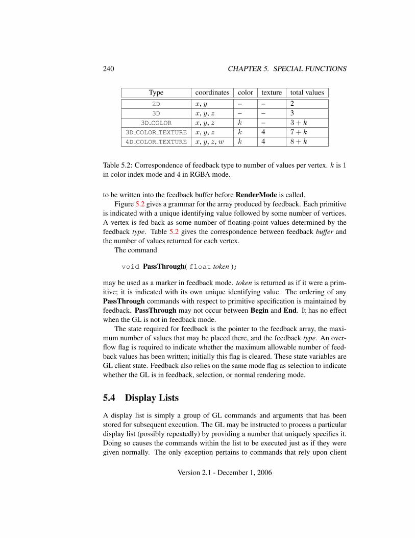
240 CHAPTER 5. SPECIAL FUNCTIONS
Type coordinates color texture total values2D x, y – – 23D x, y, z – – 3
3D COLOR x, y, z k – 3 + k
3D COLOR TEXTURE x, y, z k 4 7 + k
4D COLOR TEXTURE x, y, z, w k 4 8 + k
Table 5.2: Correspondence of feedback type to number of values per vertex. k is 1in color index mode and 4 in RGBA mode.
to be written into the feedback buffer before RenderMode is called.Figure 5.2 gives a grammar for the array produced by feedback. Each primitive
is indicated with a unique identifying value followed by some number of vertices.A vertex is fed back as some number of floating-point values determined by thefeedback type. Table 5.2 gives the correspondence between feedback buffer andthe number of values returned for each vertex.
The command
void PassThrough( float token );
may be used as a marker in feedback mode. token is returned as if it were a prim-itive; it is indicated with its own unique identifying value. The ordering of anyPassThrough commands with respect to primitive specification is maintained byfeedback. PassThrough may not occur between Begin and End. It has no effectwhen the GL is not in feedback mode.
The state required for feedback is the pointer to the feedback array, the maxi-mum number of values that may be placed there, and the feedback type. An over-flow flag is required to indicate whether the maximum allowable number of feed-back values has been written; initially this flag is cleared. These state variables areGL client state. Feedback also relies on the same mode flag as selection to indicatewhether the GL is in feedback, selection, or normal rendering mode.
5.4 Display Lists
A display list is simply a group of GL commands and arguments that has beenstored for subsequent execution. The GL may be instructed to process a particulardisplay list (possibly repeatedly) by providing a number that uniquely specifies it.Doing so causes the commands within the list to be executed just as if they weregiven normally. The only exception pertains to commands that rely upon client
Version 2.1 - December 1, 2006
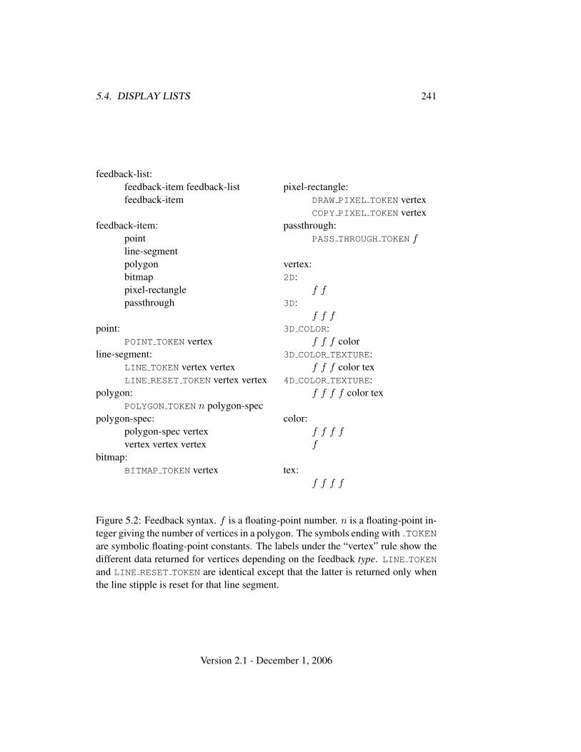
5.4. DISPLAY LISTS 241
feedback-list:feedback-item feedback-listfeedback-item
feedback-item:pointline-segmentpolygonbitmappixel-rectanglepassthrough
point:POINT TOKEN vertex
line-segment:LINE TOKEN vertex vertexLINE RESET TOKEN vertex vertex
polygon:POLYGON TOKEN n polygon-spec
polygon-spec:polygon-spec vertexvertex vertex vertex
bitmap:BITMAP TOKEN vertex
pixel-rectangle:DRAW PIXEL TOKEN vertexCOPY PIXEL TOKEN vertex
passthrough:PASS THROUGH TOKEN f
vertex:2D:
f f3D:
f f f3D COLOR:
f f f color3D COLOR TEXTURE:
f f f color tex4D COLOR TEXTURE:
f f f f color tex
color:f f f ff
tex:f f f f
Figure 5.2: Feedback syntax. f is a floating-point number. n is a floating-point in-teger giving the number of vertices in a polygon. The symbols ending with TOKENare symbolic floating-point constants. The labels under the “vertex” rule show thedifferent data returned for vertices depending on the feedback type. LINE TOKEN
and LINE RESET TOKEN are identical except that the latter is returned only whenthe line stipple is reset for that line segment.
Version 2.1 - December 1, 2006
242 CHAPTER 5. SPECIAL FUNCTIONS
state. When such a command is accumulated into the display list (that is, whenissued, not when executed), the client state in effect at that time applies to the com-mand. Only server state is affected when the command is executed. As always,pointers which are passed as arguments to commands are dereferenced when thecommand is issued. (Vertex array pointers are dereferenced when the commandsArrayElement, DrawArrays, DrawElements, or DrawRangeElements are ac-cumulated into a display list.)
A display list is begun by calling
void NewList( uint n, enum mode );
n is a positive integer to which the display list that follows is assigned, and mode is asymbolic constant that controls the behavior of the GL during display list creation.If mode is COMPILE, then commands are not executed as they are placed in thedisplay list. If mode is COMPILE AND EXECUTE then commands are executed asthey are encountered, then placed in the display list. If n = 0, then the errorINVALID VALUE is generated.
After calling NewList all subsequent GL commands are placed in the displaylist (in the order the commands are issued) until a call to
void EndList( void );
occurs, after which the GL returns to its normal command execution state. It isonly when EndList occurs that the specified display list is actually associated withthe index indicated with NewList. The error INVALID OPERATION is generatedif EndList is called without a previous matching NewList, or if NewList is calleda second time before calling EndList. The error OUT OF MEMORY is generated ifEndList is called and the specified display list cannot be stored because insufficientmemory is available. In this case GL implementations of revision 1.1 or greaterinsure that no change is made to the previous contents of the display list, if any,and that no other change is made to the GL state, except for the state changed byexecution of GL commands when the display list mode is COMPILE AND EXECUTE.
Once defined, a display list is executed by calling
void CallList( uint n );
n gives the index of the display list to be called. This causes the commands savedin the display list to be executed, in order, just as if they were issued without usinga display list. If n = 0, then the error INVALID VALUE is generated.
The command
Version 2.1 - December 1, 2006
5.4. DISPLAY LISTS 243
void CallLists( sizei n, enum type, void *lists );
provides an efficient means for executing a number of display lists. n is an in-teger indicating the number of display lists to be called, and lists is a pointerthat points to an array of offsets. Each offset is constructed as determined bylists as follows. First, type may be one of the constants BYTE, UNSIGNED BYTE,SHORT, UNSIGNED SHORT, INT, UNSIGNED INT, or FLOAT indicating that the ar-ray pointed to by lists is an array of bytes, unsigned bytes, shorts, unsigned shorts,integers, unsigned integers, or floats, respectively. In this case each offset is foundby simply converting each array element to an integer (floating point values aretruncated). Further, type may be one of 2 BYTES, 3 BYTES, or 4 BYTES, indicat-ing that the array contains sequences of 2, 3, or 4 unsigned bytes, in which caseeach integer offset is constructed according to the following algorithm:
offset← 0for i = 1 to b
offset← offset shifted left 8 bitsoffset← offset + byteadvance to next byte in the array
b is 2, 3, or 4, as indicated by type. If n = 0, CallLists does nothing.Each of the n constructed offsets is taken in order and added to a display list
base to obtain a display list number. For each number, the indicated display list isexecuted. The base is set by calling
void ListBase( uint base );
to specify the offset.Indicating a display list index that does not correspond to any display list has no
effect. CallList or CallLists may appear inside a display list. (If the mode suppliedto NewList is COMPILE AND EXECUTE, then the appropriate lists are executed,but the CallList or CallLists, rather than those lists’ constituent commands, isplaced in the list under construction.) To avoid the possibility of infinite recursionresulting from display lists calling one another, an implementation dependent limitis placed on the nesting level of display lists during display list execution. Thislimit must be at least 64.
Two commands are provided to manage display list indices.
uint GenLists( sizei s );
returns an integer n such that the indices n, . . . , n+s−1 are previously unused (i.e.there are s previously unused display list indices starting at n). GenLists also has
Version 2.1 - December 1, 2006
244 CHAPTER 5. SPECIAL FUNCTIONS
the effect of creating an empty display list for each of the indices n, . . . , n+ s− 1,so that these indices all become used. GenLists returns 0 if there is no group of scontiguous previously unused display list indices, or if s = 0.
boolean IsList( uint list );
returns TRUE if list is the index of some display list.A contiguous group of display lists may be deleted by calling
void DeleteLists( uint list, sizei range );
where list is the index of the first display list to be deleted and range is the numberof display lists to be deleted. All information about the display lists is lost, and theindices become unused. Indices to which no display list corresponds are ignored.If range = 0, nothing happens.
Certain commands, when called while compiling a display list, are not com-piled into the display list but are executed immediately. These commands fall inseveral categories including
Display lists: GenLists and DeleteLists.Render modes: FeedbackBuffer, SelectBuffer, and RenderMode.Vertex arrays: ClientActiveTexture, ColorPointer, EdgeFlagPointer, Fog-
CoordPointer, IndexPointer, InterleavedArrays, NormalPointer, Secondary-ColorPointer, TexCoordPointer, VertexAttribPointer, and VertexPointer.
Client state: EnableClientState, DisableClientState, EnableVertexAttrib-Array, DisableVertexAttribArray, PushClientAttrib, and PopClientAttrib.
Pixels and textures: PixelStore, ReadPixels, GenTextures, DeleteTextures,and AreTexturesResident.
Occlusion queries: GenQueries and DeleteQueries.Vertex buffer objects: GenBuffers, DeleteBuffers, BindBuffer, BufferData,
BufferSubData, MapBuffer, and UnmapBuffer.Program and shader objects: CreateProgram, CreateShader, DeletePro-
gram, DeleteShader, AttachShader, DetachShader, BindAttribLocation,CompileShader, ShaderSource, LinkProgram, and ValidateProgram.
GL command stream management: Finish and Flush.Other queries: All query commands whose names begin with Get and Is (see
chapter 6).GL commands that source data from buffer objects dereference the buffer ob-
ject data in question at display list compile time, rather than encoding the bufferID and buffer offset into the display list. Only GL commands that are executedimmediately, rather than being compiled into a display list, are permitted to use abuffer object as a data sink.
Version 2.1 - December 1, 2006
5.5. FLUSH AND FINISH 245
TexImage3D, TexImage2D, TexImage1D, Histogram, and Col-orTable are executed immediately when called with the correspond-ing proxy arguments PROXY TEXTURE 3D; PROXY TEXTURE 2D orPROXY TEXTURE CUBE MAP; PROXY TEXTURE 1D; PROXY HISTOGRAM;and PROXY COLOR TABLE, PROXY POST CONVOLUTION COLOR TABLE, orPROXY POST COLOR MATRIX COLOR TABLE.
When a program object is in use, a display list may be executed whose vertexattribute calls do not match up exactly with what is expected by the vertex shadercontained in that program object. Handling of this mismatch is described in sec-tion 2.15.3.
Display lists require one bit of state to indicate whether a GL command shouldbe executed immediately or placed in a display list. In the initial state, commandsare executed immediately. If the bit indicates display list creation, an index isrequired to indicate the current display list being defined. Another bit indicates,during display list creation, whether or not commands should be executed as theyare compiled into the display list. One integer is required for the current ListBasesetting; its initial value is zero. Finally, state must be maintained to indicate whichintegers are currently in use as display list indices. In the initial state, no indicesare in use.
5.5 Flush and Finish
The command
void Flush( void );
indicates that all commands that have previously been sent to the GL must completein finite time.
The command
void Finish( void );
forces all previous GL commands to complete. Finish does not return until alleffects from previously issued commands on GL client and server state and theframebuffer are fully realized.
5.6 Hints
Certain aspects of GL behavior, when there is room for variation, may be controlledwith hints. A hint is specified using
Version 2.1 - December 1, 2006
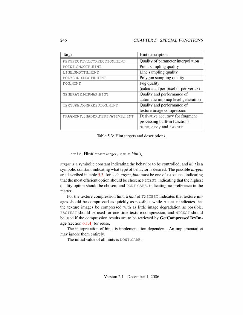
246 CHAPTER 5. SPECIAL FUNCTIONS
Target Hint descriptionPERSPECTIVE CORRECTION HINT Quality of parameter interpolationPOINT SMOOTH HINT Point sampling qualityLINE SMOOTH HINT Line sampling qualityPOLYGON SMOOTH HINT Polygon sampling qualityFOG HINT Fog quality
(calculated per-pixel or per-vertex)GENERATE MIPMAP HINT Quality and performance of
automatic mipmap level generationTEXTURE COMPRESSION HINT Quality and performance of
texture image compressionFRAGMENT SHADER DERIVATIVE HINT Derivative accuracy for fragment
processing built-in functionsdFdx, dFdy and fwidth
Table 5.3: Hint targets and descriptions.
void Hint( enum target, enum hint );
target is a symbolic constant indicating the behavior to be controlled, and hint is asymbolic constant indicating what type of behavior is desired. The possible targetsare described in table 5.3; for each target, hint must be one of FASTEST, indicatingthat the most efficient option should be chosen; NICEST, indicating that the highestquality option should be chosen; and DONT CARE, indicating no preference in thematter.
For the texture compression hint, a hint of FASTEST indicates that texture im-ages should be compressed as quickly as possible, while NICEST indicates thatthe texture images be compressed with as little image degradation as possible.FASTEST should be used for one-time texture compression, and NICEST shouldbe used if the compression results are to be retrieved by GetCompressedTexIm-age (section 6.1.4) for reuse.
The interpretation of hints is implementation dependent. An implementationmay ignore them entirely.
The initial value of all hints is DONT CARE.
Version 2.1 - December 1, 2006
Chapter 6
State and State Requests
The state required to describe the GL machine is enumerated in section 6.2. Moststate is set through the calls described in previous chapters, and can be queriedusing the calls described in section 6.1.
6.1 Querying GL State
6.1.1 Simple Queries
Much of the GL state is completely identified by symbolic constants. The valuesof these state variables can be obtained using a set of Get commands. There arefour commands for obtaining simple state variables:
void GetBooleanv( enum value, boolean *data );void GetIntegerv( enum value, int *data );void GetFloatv( enum value, float *data );void GetDoublev( enum value, double *data );
The commands obtain boolean, integer, floating-point, or double-precision statevariables. value is a symbolic constant indicating the state variable to return. datais a pointer to a scalar or array of the indicated type in which to place the returneddata. In addition
boolean IsEnabled( enum value );
can be used to determine if value is currently enabled (as with Enable) or disabled.
247
248 CHAPTER 6. STATE AND STATE REQUESTS
6.1.2 Data Conversions
If a Get command is issued that returns value types different from the type of thevalue being obtained, a type conversion is performed. If GetBooleanv is called,a floating-point or integer value converts to FALSE if and only if it is zero (oth-erwise it converts to TRUE). If GetIntegerv (or any of the Get commands below)is called, a boolean value is interpreted as either 1 or 0, and a floating-point valueis rounded to the nearest integer, unless the value is an RGBA color component,a DepthRange value, a depth buffer clear value, or a normal coordinate. In thesecases, the Get command converts the floating-point value to an integer accordingthe INT entry of table 4.7; a value not in [−1, 1] converts to an undefined value.If GetFloatv is called, a boolean value is interpreted as either 1.0 or 0.0, an in-teger is coerced to floating-point, and a double-precision floating-point value isconverted to single-precision. Analogous conversions are carried out in the case ofGetDoublev. If a value is so large in magnitude that it cannot be represented withthe requested type, then the nearest value representable using the requested type isreturned.
Unless otherwise indicated, multi-valued state variables return their multiplevalues in the same order as they are given as arguments to the commands that setthem. For instance, the two DepthRange parameters are returned in the order nfollowed by f. Similarly, points for evaluator maps are returned in the order thatthey appeared when passed to Map1. Map2 returns Rij in the [(uorder)i + j]thblock of values (see page 231 for i, j, uorder, and Rij).
Matrices may be queried and returned in transposed form by calling Get-Booleanv, GetIntegerv, GetFloatv, and GetDoublev with pname set toone of TRANSPOSE MODELVIEW MATRIX, TRANSPOSE PROJECTION MATRIX,TRANSPOSE TEXTURE MATRIX, or TRANSPOSE COLOR MATRIX. The effect of
GetFloatv(TRANSPOSE MODELVIEW MATRIX,m);
is the same as the effect of the command sequence
GetFloatv(MODELVIEW MATRIX,m);m = mT;
Similar conversions occur when querying TRANSPOSE PROJECTION MATRIX,TRANSPOSE TEXTURE MATRIX, and TRANSPOSE COLOR MATRIX.
Most texture state variables are qualified by the value of ACTIVE TEXTURE
to determine which server texture state vector is queried. Client tex-ture state variables such as texture coordinate array pointers are qual-ified by the value of CLIENT ACTIVE TEXTURE. Tables 6.5, 6.6, 6.10,
Version 2.1 - December 1, 2006
6.1. QUERYING GL STATE 249
6.16, 6.19, and 6.34 indicate those state variables which are qualified byACTIVE TEXTURE or CLIENT ACTIVE TEXTURE during state queries. Queriesof texture state variables corresponding to texture coordinate processingunits (namely, TexGen state and enables, and matrices) will generate anINVALID OPERATION error if the value of ACTIVE TEXTURE is greater than orequal to MAX TEXTURE COORDS. All other texture state queries will result in anINVALID OPERATION error if the value of ACTIVE TEXTURE is greater than orequal to MAX COMBINED TEXTURE IMAGE UNITS.
6.1.3 Enumerated Queries
Other commands exist to obtain state variables that are identified by a category(clip plane, light, material, etc.) as well as a symbolic constant. These are
void GetClipPlane( enum plane, double eqn[4] );void GetLight{if}v( enum light, enum value, T data );void GetMaterial{if}v( enum face, enum value, T data );void GetTexEnv{if}v( enum env, enum value, T data );void GetTexGen{ifd}v( enum coord, enum value, T data );void GetTexParameter{if}v( enum target, enum value,
T data );void GetTexLevelParameter{if}v( enum target, int lod,
enum value, T data );void GetPixelMap{ui us f}v( enum map, T data );void GetMap{ifd}v( enum map, enum value, T data );void GetBufferParameteriv( enum target, enum value,
T data );
GetClipPlane always returns four double-precision values in eqn; these are thecoefficients of the plane equation of plane in eye coordinates (these coordinatesare those that were computed when the plane was specified).
GetLight places information about value (a symbolic constant) for light (also asymbolic constant) in data. POSITION or SPOT DIRECTION returns values in eyecoordinates (again, these are the coordinates that were computed when the positionor direction was specified).
GetMaterial, GetTexGen, GetTexEnv, GetTexParameter, and GetBuffer-Parameter are similar to GetLight, placing information about value for the targetindicated by their first argument into data. The face argument to GetMaterialmust be either FRONT or BACK, indicating the front or back material, respectively.The env argument to GetTexEnv must be either POINT SPRITE, TEXTURE ENV,
Version 2.1 - December 1, 2006
250 CHAPTER 6. STATE AND STATE REQUESTS
or TEXTURE FILTER CONTROL. The coord argument to GetTexGen must be oneof S, T, R, or Q. For GetTexGen, EYE LINEAR coefficients are returned in the eyecoordinates that were computed when the plane was specified; OBJECT LINEAR
coefficients are returned in object coordinates.GetTexParameter
parameter target may be one of TEXTURE 1D, TEXTURE 2D, TEXTURE 3D, orTEXTURE CUBE MAP, indicating the currently bound one-, two-, three-dimensional,or cube map texture object. GetTexLevelParameter parameter target may be oneof TEXTURE 1D, TEXTURE 2D, TEXTURE 3D, TEXTURE CUBE MAP POSITIVE X,TEXTURE CUBE MAP NEGATIVE X, TEXTURE CUBE MAP POSITIVE Y,TEXTURE CUBE MAP NEGATIVE Y, TEXTURE CUBE MAP POSITIVE Z,TEXTURE CUBE MAP NEGATIVE Z, PROXY TEXTURE 1D, PROXY TEXTURE 2D,PROXY TEXTURE 3D, or PROXY TEXTURE CUBE MAP, indicating the one-, two-, orthree-dimensional texture object, or one of the six distinct 2D images making upthe cube map texture object or one-, two-, three-dimensional, or cube map proxystate vector. Note that TEXTURE CUBE MAP is not a valid target parameter forGetTexLevelParameter, because it does not specify a particular cube map face.value is a symbolic value indicating which texture parameter is to be obtained.For GetTexParameter, value must be either TEXTURE RESIDENT, or one of thesymbolic values in table 3.18. The lod argument to GetTexLevelParameter de-termines which level-of-detail’s state is returned. If the lod argument is less thanzero or if it is larger than the maximum allowable level-of-detail then the errorINVALID VALUE occurs.
For texture images with uncompressed internal formats, queries ofvalue of TEXTURE RED SIZE, TEXTURE GREEN SIZE, TEXTURE BLUE SIZE,TEXTURE ALPHA SIZE, TEXTURE LUMINANCE SIZE, TEXTURE DEPTH SIZE,and TEXTURE INTENSITY SIZE return the actual resolutions of the stored im-age array components, not the resolutions specified when the image array wasdefined. For texture images with a compressed internal format, the resolutionsreturned specify the component resolution of an uncompressed internal format thatproduces an image of roughly the same quality as the compressed image in ques-tion. Since the quality of the implementation’s compression algorithm is likelydata-dependent, the returned component sizes should be treated only as rough ap-proximations.
Querying value TEXTURE COMPRESSED IMAGE SIZE returns thesize (in ubytes) of the compressed texture image that would bereturned by GetCompressedTexImage (section 6.1.4). QueryingTEXTURE COMPRESSED IMAGE SIZE is not allowed on texture images withan uncompressed internal format or on proxy targets and will result in anINVALID OPERATION error if attempted.
Version 2.1 - December 1, 2006
6.1. QUERYING GL STATE 251
Queries of value TEXTURE WIDTH, TEXTURE HEIGHT, TEXTURE DEPTH, andTEXTURE BORDER return the width, height, depth, and border as specified whenthe image array was created. The internal format of the image array is queriedas TEXTURE INTERNAL FORMAT, or as TEXTURE COMPONENTS for compatibilitywith GL version 1.0.
For GetPixelMap, the map must be a map name from table 3.3. For GetMap,map must be one of the map types described in section 5.1, and value mustbe one of ORDER, COEFF, or DOMAIN. The GetPixelMapfv, GetPixelMapuiv,and GetPixelMapusv commands write all the values in the named pixel mapto data. If a pixel pack buffer is bound (as indicated by a non-zero value ofPIXEL PACK BUFFER BINDING), data is an offset into the pixel pack buffer; oth-erwise, data is a pointer to client memory. All pixel storage and pixel trans-fer modes are ignored when returning a pixel map. n machine units are writtenwhere n is the size of the pixel map times the size of FLOAT, UNSIGNED INT,or UNSIGNED SHORT respectively in basic machine units. If a pixel pack bufferobject is bound and data + n is greater than the size of the pixel buffer, anINVALID OPERATION error results. If a pixel pack buffer object is bound anddata is not evenly divisible by the number of basic machine units needed tostore in memory a FLOAT, UNSIGNED INT, or UNSIGNED SHORT respectively, anINVALID OPERATION error results.
6.1.4 Texture Queries
The command
void GetTexImage( enum tex, int lod, enum format,enum type, void *img );
is used to obtain texture images. It is somewhat different from the other get com-mands; tex is a symbolic value indicating which texture (or texture face in the caseof a cube map texture target name) is to be obtained. TEXTURE 1D, TEXTURE 2D,and TEXTURE 3D indicate a one-, two-, or three-dimensional texture respectively,while TEXTURE CUBE MAP POSITIVE X, TEXTURE CUBE MAP NEGATIVE X,TEXTURE CUBE MAP POSITIVE Y, TEXTURE CUBE MAP NEGATIVE Y,TEXTURE CUBE MAP POSITIVE Z, and TEXTURE CUBE MAP NEGATIVE Z indi-cate the respective face of a cube map texture. lod is a level-of-detail number,format is a pixel format from table 3.6, type is a pixel type from table 3.5.
GetTexImage obtains component groups from a texture image with theindicated level-of-detail. Calling GetTexImage with a color format (oneof RED, GREEN, BLUE, ALPHA, RGB, BGR, RGBA, BGRA, LUMINANCE, or
Version 2.1 - December 1, 2006

252 CHAPTER 6. STATE AND STATE REQUESTS
LUMINANCE ALPHA) when the base internal format of the texture image is not acolor format, or with a format of DEPTH COMPONENT when the base internal formatis not a depth format, causes the error INVALID OPERATION. If the base internalformat is a color format then the components are assigned among R, G, B, and Aaccording to table 6.1, starting with the first group in the first row, and continuingby obtaining groups in order from each row and proceeding from the first row tothe last, and from the first image to the last for three-dimensional textures. If thebase internal format is DEPTH COMPONENT, then each depth component is assignedwith the same ordering of rows and images. These groups are then packed andplaced in client or pixel buffer object memory. If a pixel pack buffer is bound (asindicated by a non-zero value of PIXEL PACK BUFFER BINDING), img is an offsetinto the pixel pack buffer; otherwise, img is a pointer to client memory. No pixeltransfer operations are performed on this image, but pixel storage modes that areapplicable to ReadPixels are applied.
For three-dimensional textures, pixel storage operations are applied as if theimage were two-dimensional, except that the additional pixel storage state valuesPACK IMAGE HEIGHT and PACK SKIP IMAGES are applied. The correspondenceof texels to memory locations is as defined for TexImage3D in section 3.8.1.
The row length, number of rows, image depth, and number of images are de-termined by the size of the texture image (including any borders). Calling GetTex-Image with lod less than zero or larger than the maximum allowable causes theerror INVALID VALUE. Calling GetTexImage with a format of COLOR INDEX orSTENCIL INDEX causes the error INVALID ENUM. If a pixel pack buffer objectis bound and packing the texture image into the buffer’s memory would exceed thesize of the buffer, an INVALID OPERATION error results. If a pixel pack bufferobject is bound and img is not evenly divisible by the number of basic machineunits needed to store in memory a FLOAT, UNSIGNED INT, or UNSIGNED SHORT
respectively, an INVALID OPERATION error results.The command
void GetCompressedTexImage( enum target, int lod,void *img );
is used to obtain texture images stored in compressed form. The parameters target,lod, and img are interpreted in the same manner as in GetTexImage. When called,GetCompressedTexImage writes n ubytes of compressed image data to thepixel pack buffer or client memory pointed to by img, where n is the value ofTEXTURE COMPRESSED IMAGE SIZE for the texture. The compressed image datais formatted according to the definition of the texture’s internal format. All pixelstorage and pixel transfer modes are ignored when returning a compressed textureimage.
Version 2.1 - December 1, 2006
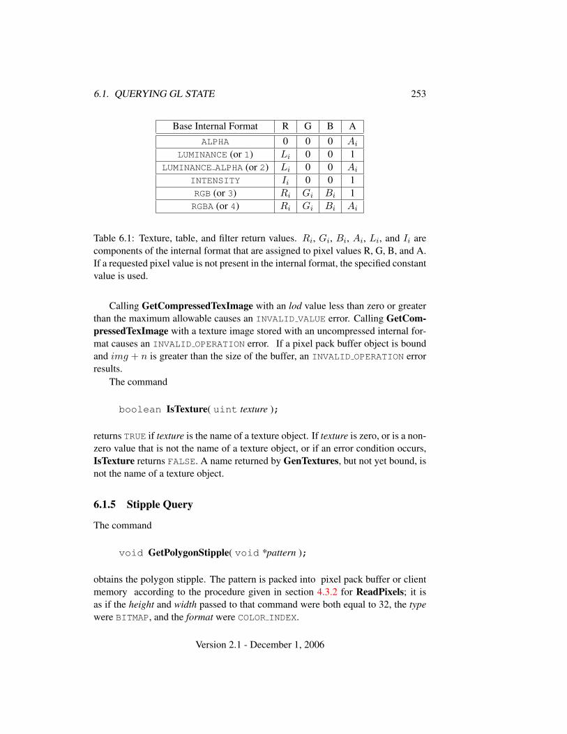
6.1. QUERYING GL STATE 253
Base Internal Format R G B AALPHA 0 0 0 Ai
LUMINANCE (or 1) Li 0 0 1LUMINANCE ALPHA (or 2) Li 0 0 Ai
INTENSITY Ii 0 0 1RGB (or 3) Ri Gi Bi 1RGBA (or 4) Ri Gi Bi Ai
Table 6.1: Texture, table, and filter return values. Ri, Gi, Bi, Ai, Li, and Ii arecomponents of the internal format that are assigned to pixel values R, G, B, and A.If a requested pixel value is not present in the internal format, the specified constantvalue is used.
Calling GetCompressedTexImage with an lod value less than zero or greaterthan the maximum allowable causes an INVALID VALUE error. Calling GetCom-pressedTexImage with a texture image stored with an uncompressed internal for-mat causes an INVALID OPERATION error. If a pixel pack buffer object is boundand img + n is greater than the size of the buffer, an INVALID OPERATION errorresults.
The command
boolean IsTexture( uint texture );
returns TRUE if texture is the name of a texture object. If texture is zero, or is a non-zero value that is not the name of a texture object, or if an error condition occurs,IsTexture returns FALSE. A name returned by GenTextures, but not yet bound, isnot the name of a texture object.
6.1.5 Stipple Query
The command
void GetPolygonStipple( void *pattern );
obtains the polygon stipple. The pattern is packed into pixel pack buffer or clientmemory according to the procedure given in section 4.3.2 for ReadPixels; it isas if the height and width passed to that command were both equal to 32, the typewere BITMAP, and the format were COLOR INDEX.
Version 2.1 - December 1, 2006
254 CHAPTER 6. STATE AND STATE REQUESTS
6.1.6 Color Matrix Query
The scale and bias variables are queried using GetFloatv with pname setto the appropriate variable name. The top matrix on the color matrixstack is returned by GetFloatv called with pname set to COLOR MATRIX orTRANSPOSE COLOR MATRIX. The depth of the color matrix stack, and the maxi-mum depth of the color matrix stack, are queried with GetIntegerv, setting pnameto COLOR MATRIX STACK DEPTH and MAX COLOR MATRIX STACK DEPTH respec-tively.
6.1.7 Color Table Query
The current contents of a color table are queried using
void GetColorTable( enum target, enum format, enum type,void *table );
target must be one of the regular color table names listed in table 3.4. format andtype accept the same values as do the corresponding parameters of GetTexImage,except that a format of DEPTH COMPONENT causes the error INVALID ENUM. Theone-dimensional color table image is returned to pixel pack buffer or client mem-ory starting at table. No pixel transfer operations are performed on this image, butpixel storage modes that are applicable to ReadPixels are performed. Color com-ponents that are requested in the specified format, but which are not included in theinternal format of the color lookup table, are returned as zero. The assignments ofinternal color components to the components requested by format are described intable 6.1.
The functions
void GetColorTableParameter{if}v( enum target,enum pname, T params );
are used for integer and floating point query.target must be one of the regular or proxy color table names listed in
table 3.4. pname is one of COLOR TABLE SCALE, COLOR TABLE BIAS,COLOR TABLE FORMAT, COLOR TABLE WIDTH, COLOR TABLE RED SIZE,COLOR TABLE GREEN SIZE, COLOR TABLE BLUE SIZE,COLOR TABLE ALPHA SIZE, COLOR TABLE LUMINANCE SIZE, orCOLOR TABLE INTENSITY SIZE. The value of the specified parameter isreturned in params.
Version 2.1 - December 1, 2006
6.1. QUERYING GL STATE 255
6.1.8 Convolution Query
The current contents of a convolution filter image are queried with the command
void GetConvolutionFilter( enum target, enum format,enum type, void *image );
target must be CONVOLUTION 1D or CONVOLUTION 2D. format and type acceptthe same values as do the corresponding parameters of GetTexImage, exceptthat a format of DEPTH COMPONENT causes the error INVALID ENUM. The one-dimensional or two-dimensional images is returned to pixel pack buffer or clientmemory starting at image. Pixel processing and component mapping are identicalto those of GetTexImage.
The current contents of a separable filter image are queried using
void GetSeparableFilter( enum target, enum format,enum type, void *row, void *column, void *span );
target must be SEPARABLE 2D. format and type accept the same values as do thecorresponding parameters of GetTexImage. The row and column images are re-turned to pixel pack buffer or client memory starting at row and column respec-tively. span is currently unused. Pixel processing and component mapping areidentical to those of GetTexImage.
The functions
void GetConvolutionParameter{if}v( enum target,enum pname, T params );
are used for integer and floating point query. target must beCONVOLUTION 1D, CONVOLUTION 2D, or SEPARABLE 2D. pname isone of CONVOLUTION BORDER COLOR, CONVOLUTION BORDER MODE,CONVOLUTION FILTER SCALE, CONVOLUTION FILTER BIAS,CONVOLUTION FORMAT, CONVOLUTION WIDTH, CONVOLUTION HEIGHT,MAX CONVOLUTION WIDTH, or MAX CONVOLUTION HEIGHT. The value of thespecified parameter is returned in params.
6.1.9 Histogram Query
The current contents of the histogram table are queried using
void GetHistogram( enum target, boolean reset,enum format, enum type, void* values );
Version 2.1 - December 1, 2006
256 CHAPTER 6. STATE AND STATE REQUESTS
target must be HISTOGRAM. type and format accept the same values as do the corre-sponding parameters of GetTexImage, except that a format of DEPTH COMPONENT
causes the error INVALID ENUM. The one-dimensional histogram table image is re-turned to pixel pack buffer or client memory starting at type. Pixel processing andcomponent mapping are identical to those of GetTexImage, except that instead ofapplying the Final Conversion pixel storage mode, component values are simplyclamped to the range of the target data type.
If reset is TRUE, then all counters of all elements of the histogram are reset tozero. Counters are reset whether returned or not.
No counters are modified if reset is FALSE.Calling
void ResetHistogram( enum target );
resets all counters of all elements of the histogram table to zero. target must beHISTOGRAM.
It is not an error to reset or query the contents of a histogram table with zeroentries.
The functions
void GetHistogramParameter{if}v( enum target,enum pname, T params );
are used for integer and floating point query. target must be HISTOGRAM orPROXY HISTOGRAM. pname is one of HISTOGRAM FORMAT, HISTOGRAM WIDTH,HISTOGRAM RED SIZE, HISTOGRAM GREEN SIZE, HISTOGRAM BLUE SIZE,HISTOGRAM ALPHA SIZE, or HISTOGRAM LUMINANCE SIZE. pname may beHISTOGRAM SINK only for target HISTOGRAM. The value of the specifiedparameter is returned in params.
6.1.10 Minmax Query
The current contents of the minmax table are queried using
void GetMinmax( enum target, boolean reset, enum format,enum type, void* values );
target must be MINMAX. type and format accept the same values as do the corre-sponding parameters of GetTexImage, except that a format of DEPTH COMPONENT
causes the error INVALID ENUM. A one-dimensional image of width 2 is returned
Version 2.1 - December 1, 2006

6.1. QUERYING GL STATE 257
to pixel pack buffer or client memory starting at values. Pixel processing andcomponent mapping are identical to those of GetTexImage.
If reset is TRUE, then each minimum value is reset to the maximum repre-sentable value, and each maximum value is reset to the minimum representablevalue. All values are reset, whether returned or not.
No values are modified if reset is FALSE.Calling
void ResetMinmax( enum target );
resets all minimum and maximum values of target to to their maximum and mini-mum representable values, respectively, target must be MINMAX.
The functions
void GetMinmaxParameter{if}v( enum target, enum pname,T params );
are used for integer and floating point query. target must be MINMAX. pname isMINMAX FORMAT or MINMAX SINK. The value of the specified parameter is re-turned in params.
6.1.11 Pointer and String Queries
The command
void GetPointerv( enum pname, void **params );
obtains the pointer or pointers named pname in thearray params. The possible values for pname areSELECTION BUFFER POINTER, FEEDBACK BUFFER POINTER,VERTEX ARRAY POINTER, NORMAL ARRAY POINTER, COLOR ARRAY POINTER,SECONDARY COLOR ARRAY POINTER, INDEX ARRAY POINTER,TEXTURE COORD ARRAY POINTER, FOG COORD ARRAY POINTER, andEDGE FLAG ARRAY POINTER. Each returns a single pointer value.
Finally,
ubyte *GetString( enum name );
returns a pointer to a static string describing some aspect of the current GLconnection1. The possible values for name are VENDOR, RENDERER, VERSION,
1Applications making copies of these static strings should never use a fixed-length buffer, becausethe strings may grow unpredictably between releases, resulting in buffer overflow when copying.This is particularly true of the EXTENSIONS string, which has become extremely long in someGL implementations.
Version 2.1 - December 1, 2006

258 CHAPTER 6. STATE AND STATE REQUESTS
SHADING LANGUAGE VERSION, and EXTENSIONS. The format of the RENDERERand VENDOR strings is implementation dependent. The EXTENSIONS string con-tains a space separated list of extension names (the extension names themselves donot contain any spaces). The VERSION and SHADING LANGUAGE VERSION stringsare laid out as follows:
<version number><space><vendor-specific information>
The version number is either of the form major number.minor number or ma-jor number.minor number.release number, where the numbers all have one ormore digits. The release number and vendor specific information are optional.However, if present, then they pertain to the server and their format and contentsare implementation dependent.
GetString returns the version number (returned in the VERSION string) andthe extension names (returned in the EXTENSIONS string) that can be supportedon the connection. Thus, if the client and server support different versions and/orextensions, a compatible version and list of extensions is returned.
6.1.12 Occlusion Queries
The command
boolean IsQuery( uint id );
returns TRUE if id is the name of a query object. If id is zero, or if id is a non-zerovalue that is not the name of a query object, IsQuery returns FALSE.
Information about a query target can be queried with the command
void GetQueryiv( enum target, enum pname, int *params );
If pname is CURRENT QUERY, the name of the currently active query for target, orzero if no query is active, will be placed in params.
If pname is QUERY COUNTER BITS, the number of bits in the counter for targetwill be placed in params. The number of query counter bits may be zero, in whichcase the counter contains no useful information. Otherwise, the minimum numberof bits allowed is a function of the implementation’s maximum viewport dimen-sions (MAX VIEWPORT DIMS). In this case, the counter must be able to representat least two overdraws for every pixel in the viewport The formula to compute theallowable minimum value (where n is the minimum number of bits) is:
n = min{32, dlog2(maxV iewportWidth ∗maxV iewportHeight ∗ 2)e}
The state of a query object can be queried with the commands
Version 2.1 - December 1, 2006
6.1. QUERYING GL STATE 259
void GetQueryObjectiv( uint id, enum pname,int *params );
void GetQueryObjectuiv( uint id, enum pname,uint *params );
If id is not the name of a query object, or if the query object named by id is currentlyactive, then an INVALID OPERATION error is generated.
If pname is QUERY RESULT, then the query object’s result value is placed inparams. If the number of query counter bits for target is zero, then the result valueis always 0.
There may be an indeterminate delay before the above query returns. Ifpname is QUERY RESULT AVAILABLE, it immediately returns FALSE if such a de-lay would be required, TRUE otherwise. It must always be true that if any queryobject returns result available of TRUE, all queries issued prior to that query mustalso return TRUE.
Querying the state for any given query object forces that occlusion query tocomplete within a finite amount of time.
If multiple queries are issued on the same target and id prior to calling Get-QueryObject[u]iv, the result returned will always be from the last query issued.The results from any queries before the last one will be lost if the results are notretrieved before starting a new query on the same target and id.
6.1.13 Buffer Object Queries
The command
boolean IsBuffer( uint buffer );
returns TRUE if buffer is the name of an buffer object. If buffer is zero, or if buffer isa non-zero value that is not the name of an buffer object, IsBuffer returns FALSE.
The command
void GetBufferSubData( enum target, intptr offset,sizeiptr size, void *data );
queries the data contents of a buffer object. target is ARRAY BUFFER,ELEMENT ARRAY BUFFER, PIXEL PACK BUFFER, or PIXEL UNPACK BUFFER.offset and size indicate the range of data in the buffer object that is to be queried, interms of basic machine units. data specifies a region of client memory, size basicmachine units in length, into which the data is to be retrieved.
Version 2.1 - December 1, 2006
260 CHAPTER 6. STATE AND STATE REQUESTS
An error is generated if GetBufferSubData is executed for a buffer object thatis currently mapped.
While the data store of a buffer object is mapped, the pointer to the data storecan be queried by calling
void GetBufferPointerv( enum target, enum pname,void **params );
with target set to ARRAY BUFFER, ELEMENT ARRAY BUFFER,PIXEL PACK BUFFER, or PIXEL UNPACK BUFFER and pname set toBUFFER MAP POINTER. The single buffer map pointer is returned in *params.GetBufferPointerv returns the NULL pointer value if the buffer’s data store is notcurrently mapped, or if the requesting client did not map the buffer object’s datastore, and the implementation is unable to support mappings on multiple clients.
6.1.14 Shader and Program Queries
State stored in shader or program objects can be queried by commands that ac-cept shader or program object names. These commands will generate the errorINVALID VALUE if the provided name is not the name of either a shader or pro-gram object, and INVALID OPERATION if the provided name identifies an objectof the other type. If an error is generated, variables used to hold return values arenot modified.
The command
boolean IsShader( uint shader );
returns TRUE if shader is the name of a shader object. If shader is zero, or a non-zero value that is not the name of a shader object, IsShader returns FALSE. Noerror is generated if shader is not a valid shader object name.
The command
void GetShaderiv( uint shader, enum pname, int *params );
returns properties of the shader object named shader in params. The parametervalue to return is specified by pname.
If pname is SHADER TYPE, VERTEX SHADER is returned if shader is a ver-tex shader object, and FRAGMENT SHADER is returned if shader is a fragmentshader object. If pname is DELETE STATUS, TRUE is returned if the shaderhas been flagged for deletion and FALSE is returned otherwise. If pname isCOMPILE STATUS, TRUE is returned if the shader was last compiled successfully,
Version 2.1 - December 1, 2006
6.1. QUERYING GL STATE 261
and FALSE is returned otherwise. If pname is INFO LOG LENGTH, the length ofthe info log, including a null terminator, is returned. If there is no info log, zerois returned. If pname is SHADER SOURCE LENGTH, the length of the concatenationof the source strings making up the shader source, including a null terminator, isreturned. If no source has been defined, zero is returned.
The command
boolean IsProgram( uint program );
returns TRUE if program is the name of a program object. If program is zero,or a non-zero value that is not the name of a program object, IsProgram returnsFALSE. No error is generated if program is not a valid program object name.
The command
void GetProgramiv( uint program, enum pname,int *params );
returns properties of the program object named program in params. The parametervalue to return is specified by pname.
If pname is DELETE STATUS, TRUE is returned if the program has been flaggedfor deletion and FALSE is returned otherwise. If pname is LINK STATUS, TRUEis returned if the program was last compiled successfully, and FALSE is returnedotherwise. If pname is VALIDATE STATUS, TRUE is returned if the last call to Val-idateProgram with program was successful, and FALSE is returned otherwise. Ifpname is INFO LOG LENGTH, the length of the info log, including a null terminator,is returned. If there is no info log, 0 is returned. If pname is ATTACHED SHADERS,the number of objects attached is returned. If pname is ACTIVE ATTRIBUTES, thenumber of active attributes in program is returned. If no active attributes exist,0 is returned. If pname is ACTIVE ATTRIBUTE MAX LENGTH, the length of thelongest active attribute name, including a null terminator, is returned. If no ac-tive attributes exist, 0 is returned. If pname is ACTIVE UNIFORMS, the number ofactive uniforms is returned. If no active uniforms exist, 0 is returned. If pnameis ACTIVE UNIFORM MAX LENGTH, the length of the longest active uniform name,including a null terminator, is returned. If no active uniforms exist, 0 is returned.
The command
void GetAttachedShaders( uint program, sizei maxCount,sizei *count, uint *shaders );
returns the names of shader objects attached to program in shaders. The actualnumber of shader names written into shaders is returned in count. If no shaders are
Version 2.1 - December 1, 2006

262 CHAPTER 6. STATE AND STATE REQUESTS
attached, count is set to zero. If count is NULL then it is ignored. The maximumnumber of shader names that may be written into shaders is specified by maxCount.The number of objects attached to program is given by can be queried by callingGetProgramiv with ATTACHED SHADERS.
A string that contains information about the last compilation attempt on ashader object or last link or validation attempt on a program object, called theinfo log, can be obtained with the commands
void GetShaderInfoLog( uint shader, sizei bufSize,sizei *length, char *infoLog );
void GetProgramInfoLog( uint program, sizei bufSize,sizei *length, char *infoLog );
These commands return the info log string in infoLog. This string will be nullterminated. The actual number of characters written into infoLog, excluding thenull terminator, is returned in length. If length is NULL, then no length is returned.The maximum number of characters that may be written into infoLog, includingthe null terminator, is specified by bufSize. The number of characters in the infolog can be queried with GetShaderiv or GetProgramiv with INFO LOG LENGTH.If shader is a shader object, the returned info log will either be an empty stringor it will contain information about the last compilation attempt for that object. Ifprogram is a program object, the returned info log will either be an empty string orit will contain information about the last link attempt or last validation attempt forthat object.
The info log is typically only useful during application development and anapplication should not expect different GL implementations to produce identicalinfo logs.
The command
void GetShaderSource( uint shader, sizei bufSize,sizei *length, char *source );
returns in source the string making up the source code for the shader object shader.The string source will be null terminated. The actual number of characters writteninto source, excluding the null terminator, is returned in length. If length is NULL,no length is returned. The maximum number of characters that may be written intosource, including the null terminator, is specified by bufSize. The string source isa concatenation of the strings passed to the GL using ShaderSource. The lengthof this concatenation is given by SHADER SOURCE LENGTH, which can be queriedwith GetShaderiv.
The commands
Version 2.1 - December 1, 2006
6.1. QUERYING GL STATE 263
void GetVertexAttribdv( uint index, enum pname,double *params );
void GetVertexAttribfv( uint index, enum pname,float *params );
void GetVertexAttribiv( uint index, enum pname,int *params );
obtain the vertex attribute state named by pname for the generic ver-tex attribute numbered index and places the information in the arrayparams. pname must be one of VERTEX ATTRIB ARRAY BUFFER BINDING,VERTEX ATTRIB ARRAY ENABLED, VERTEX ATTRIB ARRAY SIZE,VERTEX ATTRIB ARRAY STRIDE, VERTEX ATTRIB ARRAY TYPE,VERTEX ATTRIB ARRAY NORMALIZED, or CURRENT VERTEX ATTRIB. Note thatall the queries except CURRENT VERTEX ATTRIB return client state. Theerror INVALID VALUE is generated if index is greater than or equal toMAX VERTEX ATTRIBS.
All but CURRENT VERTEX ATTRIB return information about generic vertex at-tribute arrays. The enable state of a generic vertex attribute array is set by thecommand EnableVertexAttribArray and cleared by DisableVertexAttribArray.The size, stride, type and normalized flag are set by the command VertexAttrib-Pointer. The query CURRENT VERTEX ATTRIB returns the current value for thegeneric attribute index. In this case the error INVALID OPERATION is generated ifindex is zero, as there is no current value for generic attribute zero.
The command
void GetVertexAttribPointerv( uint index, enum pname,void **pointer );
obtains the pointer named pname for vertex attribute numbered indexand places the information in the array pointer. pname must beVERTEX ATTRIB ARRAY POINTER. The INVALID VALUE error is generated if in-dex is greater than or equal to MAX VERTEX ATTRIBS.
The commands
void GetUniformfv( uint program, int location,float *params );
void GetUniformiv( uint program, int location,int *params );
return the value or values of the uniform at location location for program objectprogram in the array params. The type of the uniform at location determines the
Version 2.1 - December 1, 2006
264 CHAPTER 6. STATE AND STATE REQUESTS
number of values returned. The error INVALID OPERATION is generated if pro-gram has not been linked successfully, or if location is not a valid location forprogram. In order to query the values of an array of uniforms, a GetUniform*command needs to be issued for each array element. If the uniform queried is amatrix, the values of the matrix are returned in column major order. If an erroroccurred, the return parameter params will be unmodified.
6.1.15 Saving and Restoring State
Besides providing a means to obtain the values of state variables, the GL alsoprovides a means to save and restore groups of state variables. The PushAttrib,PushClientAttrib, PopAttrib and PopClientAttrib commands are used for thispurpose. The commands
void PushAttrib( bitfield mask );void PushClientAttrib( bitfield mask );
take a bitwise OR of symbolic constants indicating which groups of state variablesto push onto an attribute stack. PushAttrib uses a server attribute stack whilePushClientAttrib uses a client attribute stack. Each constant refers to a groupof state variables. The classification of each variable into a group is indicatedin the following tables of state variables. The error STACK OVERFLOW is gener-ated if PushAttrib or PushClientAttrib is executed while the corresponding stackdepth is MAX ATTRIB STACK DEPTH or MAX CLIENT ATTRIB STACK DEPTH re-spectively. Bits set in mask that do not correspond to an attribute group are ignored.The special mask values ALL ATTRIB BITS and CLIENT ALL ATTRIB BITS maybe used to push all stackable server and client state, respectively.
The commands
void PopAttrib( void );void PopClientAttrib( void );
reset the values of those state variables that were saved with the last correspondingPushAttrib or PopClientAttrib. Those not saved remain unchanged. The er-ror STACK UNDERFLOW is generated if PopAttrib or PopClientAttrib is executedwhile the respective stack is empty.
Table 6.2 shows the attribute groups with their corresponding symbolic con-stant names and stacks.
When PushAttrib is called with TEXTURE BIT set, the priorities, border col-ors, filter modes, wrap modes, and other state of the currently bound texture objects(see table 6.17), as well as the current texture bindings and enables, are pushed onto
Version 2.1 - December 1, 2006
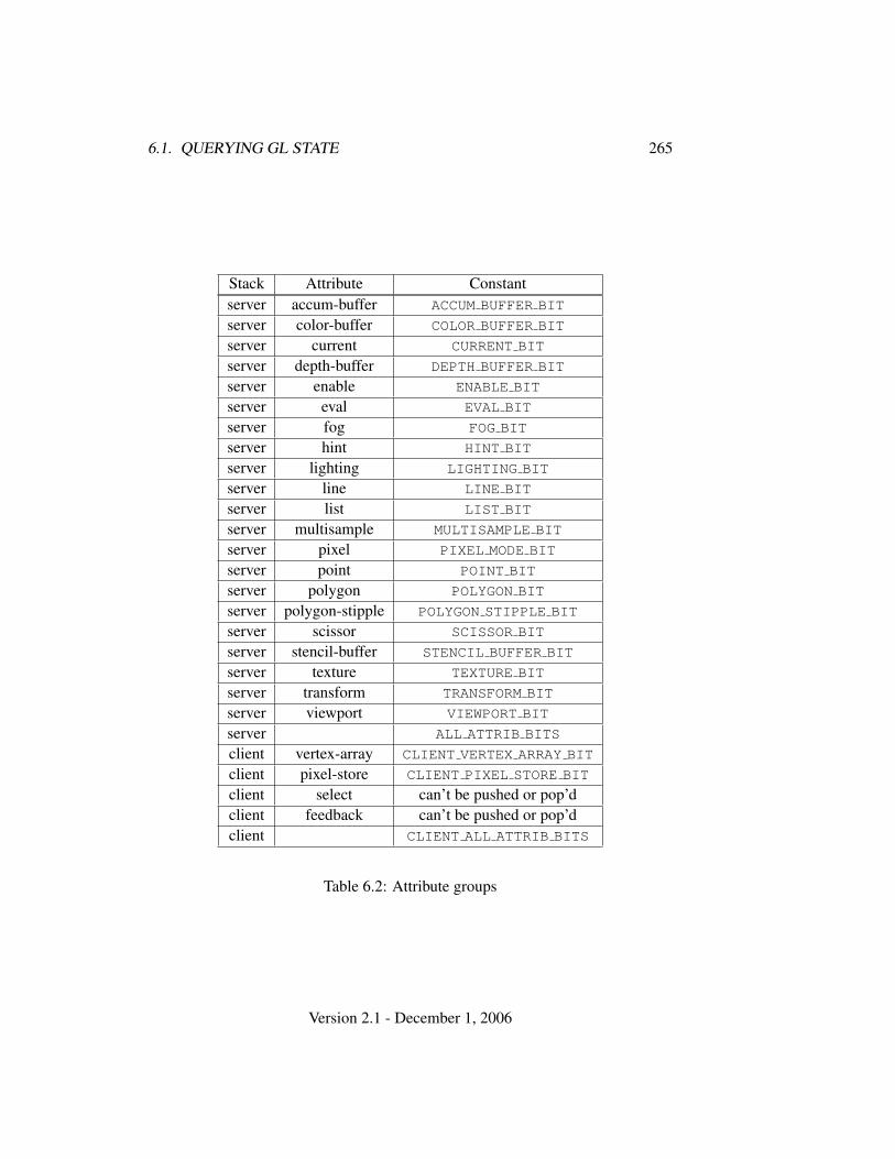
6.1. QUERYING GL STATE 265
Stack Attribute Constantserver accum-buffer ACCUM BUFFER BIT
server color-buffer COLOR BUFFER BIT
server current CURRENT BIT
server depth-buffer DEPTH BUFFER BIT
server enable ENABLE BIT
server eval EVAL BIT
server fog FOG BIT
server hint HINT BIT
server lighting LIGHTING BIT
server line LINE BIT
server list LIST BIT
server multisample MULTISAMPLE BIT
server pixel PIXEL MODE BIT
server point POINT BIT
server polygon POLYGON BIT
server polygon-stipple POLYGON STIPPLE BIT
server scissor SCISSOR BIT
server stencil-buffer STENCIL BUFFER BIT
server texture TEXTURE BIT
server transform TRANSFORM BIT
server viewport VIEWPORT BIT
server ALL ATTRIB BITS
client vertex-array CLIENT VERTEX ARRAY BIT
client pixel-store CLIENT PIXEL STORE BIT
client select can’t be pushed or pop’dclient feedback can’t be pushed or pop’dclient CLIENT ALL ATTRIB BITS
Table 6.2: Attribute groups
Version 2.1 - December 1, 2006
266 CHAPTER 6. STATE AND STATE REQUESTS
the attribute stack. (Unbound texture objects are not pushed or restored.) When anattribute set that includes texture information is popped, the bindings and enablesare first restored to their pushed values, then the bound texture object’s parametersare restored to their pushed values.
Operations on attribute groups push or pop texture state within that group forall texture units. When state for a group is pushed, all state corresponding toTEXTURE0 is pushed first, followed by state corresponding to TEXTURE1, and soon up to and including the state corresponding to TEXTUREk where k + 1 is thevalue of MAX TEXTURE UNITS. When state for a group is popped, texture state isrestored in the opposite order that it was pushed, starting with state correspondingto TEXTUREk and ending with TEXTURE0. Identical rules are observed for clienttexture state push and pop operations. Matrix stacks are never pushed or poppedwith PushAttrib, PushClientAttrib, PopAttrib, or PopClientAttrib.
The depth of each attribute stack is implementation dependent but must be atleast 16. The state required for each attribute stack is potentially 16 copies of eachstate variable, 16 masks indicating which groups of variables are stored in eachstack entry, and an attribute stack pointer. In the initial state, both attribute stacksare empty.
In the tables that follow, a type is indicated for each variable. Table 6.3 ex-plains these types. The type actually identifies all state associated with the indi-cated description; in certain cases only a portion of this state is returned. Thisis the case with all matrices, where only the top entry on the stack is returned;with clip planes, where only the selected clip plane is returned, with parametersdescribing lights, where only the value pertaining to the selected light is returned;with textures, where only the selected texture or texture parameter is returned; andwith evaluator maps, where only the selected map is returned. Finally, a “–” in theattribute column indicates that the indicated value is not included in any attributegroup (and thus can not be pushed or popped with PushAttrib, PushClientAttrib,PopAttrib, or PopClientAttrib).
The M and m entries for initial minmax table values represent the maximumand minimum possible representable values, respectively.
6.2 State Tables
The tables on the following pages indicate which state variables are obtained withwhat commands. State variables that can be obtained using any of GetBooleanv,GetIntegerv, GetFloatv, or GetDoublev are listed with just one of these com-mands – the one that is most appropriate given the type of the data to be returned.These state variables cannot be obtained using IsEnabled. However, state vari-
Version 2.1 - December 1, 2006
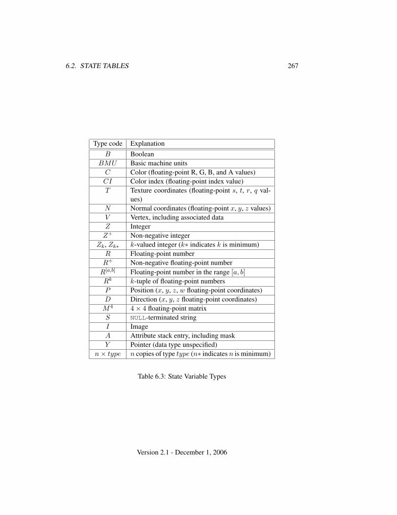
6.2. STATE TABLES 267
Type code ExplanationB Boolean
BMU Basic machine unitsC Color (floating-point R, G, B, and A values)CI Color index (floating-point index value)T Texture coordinates (floating-point s, t, r, q val-
ues)N Normal coordinates (floating-point x, y, z values)V Vertex, including associated dataZ IntegerZ+ Non-negative integer
Zk, Zk∗ k-valued integer (k∗ indicates k is minimum)R Floating-point numberR+ Non-negative floating-point number
R[a,b] Floating-point number in the range [a, b]Rk k-tuple of floating-point numbersP Position (x, y, z, w floating-point coordinates)D Direction (x, y, z floating-point coordinates)M4 4× 4 floating-point matrixS NULL-terminated stringI ImageA Attribute stack entry, including maskY Pointer (data type unspecified)
n× type n copies of type type (n∗ indicates n is minimum)
Table 6.3: State Variable Types
Version 2.1 - December 1, 2006
268 CHAPTER 6. STATE AND STATE REQUESTS
ables for which IsEnabled is listed as the query command can also be obtainedusing GetBooleanv, GetIntegerv, GetFloatv, and GetDoublev. State variablesfor which any other command is listed as the query command can be obtained onlyby using that command.
State table entries which are required only by the imaging subset (see sec-tion 3.6.2) are typeset against a gray background .
Version 2.1 - December 1, 2006
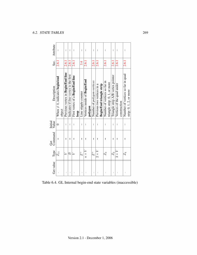
6.2. STATE TABLES 269
Get
valu
eTy
peG
etC
omm
and
Initi
alV
alue
Des
crip
tion
Sec.
Attr
ibut
e–
Z11
–0
Whe
n6=
0,in
dica
tes
begi
n/en
dob
ject
2.6.
1–
–V
––
Prev
ious
vert
exin
Beg
in/E
ndlin
e2.
6.1
––
B–
–In
dica
tes
iflin
e-ve
rtex
isth
efir
st2.
6.1
––
V–
–Fi
rstv
erte
xof
aB
egin
/End
line
loop
2.6.
1–
–Z
+–
–L
ine
stip
ple
coun
ter
3.4
––
n×
V–
–V
ertic
esin
side
ofB
egin
/End
poly
gon
2.6.
1–
–Z
+–
–N
umbe
rofp
olyg
on-v
ertic
es2.
6.1
––
2×
V–
–Pr
evio
ustw
ove
rtic
esin
aB
egin
/End
tria
ngle
stri
p2.
6.1
–
–Z
3–
–N
umbe
rofv
ertic
esso
fari
ntr
iang
lest
rip:
0,1,
orm
ore
2.6.
1–
–Z
2–
–Tr
iang
lest
rip
A/B
vert
expo
inte
r2.
6.1
––
3×
V–
–V
ertic
esof
the
quad
unde
rco
nstr
uctio
n2.
6.1
–
–Z
4–
–N
umbe
rofv
ertic
esso
fari
nqu
adst
rip:
0,1,
2,or
mor
e2.
6.1
–
Table 6.4. GL Internal begin-end state variables (inaccessible)
Version 2.1 - December 1, 2006
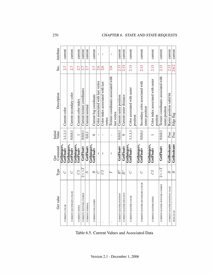
270 CHAPTER 6. STATE AND STATE REQUESTS
Get
valu
eTy
peG
etC
omm
and
Initi
alV
alue
Des
crip
tion
Sec.
Attr
ibut
e
CU
RR
EN
TC
OL
OR
CG
etIn
tege
rv,
Get
Floa
tv1,
1,1,
1C
urre
ntco
lor
2.7
curr
ent
CU
RR
EN
TSE
CO
ND
ARY
CO
LO
RC
Get
Inte
gerv
,G
etFl
oatv
0,0,
0,1
Cur
rent
seco
ndar
yco
lor
2.7
curr
ent
CU
RR
EN
TIN
DE
XC
IG
etIn
tege
rv,
Get
Floa
tv1
Cur
rent
colo
rind
ex2.
7cu
rren
tC
UR
RE
NT
TE
XT
UR
EC
OO
RD
S2∗×
TG
etFl
oatv
0,0,
0,1
Cur
rent
text
ure
coor
dina
tes
2.7
curr
ent
CU
RR
EN
TN
OR
MA
LN
Get
Floa
tv0,
0,1
Cur
rent
norm
al2.
7cu
rren
t
CU
RR
EN
TFO
GC
OO
RD
RG
etIn
tege
rv,
Get
Floa
tv0
Cur
rent
fog
coor
dina
te2.
7cu
rren
t–
C–
-C
olor
asso
ciat
edw
ithla
stve
rtex
2.6
––
CI
–-
Col
orin
dex
asso
ciat
edw
ithla
stve
rtex
2.6
–
–T
–-
Text
ure
coor
dina
tes
asso
ciat
edw
ithla
stve
rtex
2.6
–
CU
RR
EN
TR
AST
ER
POSI
TIO
NR
4G
etFl
oatv
0,0,
0,1
Cur
rent
rast
erpo
sitio
n2.
13cu
rren
tC
UR
RE
NT
RA
STE
RD
ISTA
NC
ER
+G
etFl
oatv
0C
urre
ntra
ster
dist
ance
2.13
curr
ent
CU
RR
EN
TR
AST
ER
CO
LO
RC
Get
Inte
gerv
,G
etFl
oatv
1,1,
1,1
Col
oras
soci
ated
with
rast
erpo
sitio
n2.
13cu
rren
t
CU
RR
EN
TR
AST
ER
SEC
ON
DA
RYC
OL
OR
CG
etIn
tege
rv,
Get
Floa
tv0,
0,0,
1Se
cond
ary
colo
rass
ocia
ted
with
rast
erpo
sitio
n2.
13cu
rren
t
CU
RR
EN
TR
AST
ER
IND
EX
CI
Get
Inte
gerv
,G
etFl
oatv
1C
olor
inde
xas
soci
ated
with
rast
erpo
sitio
n2.
13cu
rren
t
CU
RR
EN
TR
AST
ER
TE
XT
UR
EC
OO
RD
S2∗×
TG
etFl
oatv
0,0,
0,1
Text
ure
coor
dina
tes
asso
ciat
edw
ithra
ster
posi
tion
2.13
curr
ent
CU
RR
EN
TR
AST
ER
POSI
TIO
NVA
LID
BG
etB
oole
anv
True
Ras
terp
ositi
onva
lidbi
t2.
13cu
rren
tE
DG
EFL
AG
BG
etB
oole
anv
True
Edg
efla
g2.
6.2
curr
ent
Table 6.5. Current Values and Associated Data
Version 2.1 - December 1, 2006
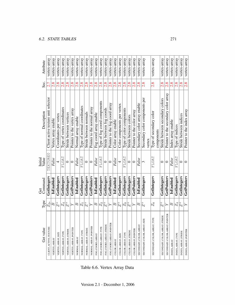
6.2. STATE TABLES 271G
etva
lue
Type
Get
Com
man
dIn
itial
Val
ueD
escr
iptio
nSe
c.A
ttrib
ute
CL
IEN
TA
CT
IVE
TE
XT
UR
EZ
2∗
Get
Inte
gerv
TEXTURE0
Clie
ntac
tive
text
ure
unit
sele
ctor
2.7
vert
ex-a
rray
VE
RT
EX
AR
RA
YB
IsE
nabl
edFa
lse
Ver
tex
arra
yen
able
2.8
vert
ex-a
rray
VE
RT
EX
AR
RA
YSI
ZE
Z+
Get
Inte
gerv
4C
oord
inat
espe
rver
tex
2.8
vert
ex-a
rray
VE
RT
EX
AR
RA
YT
YPE
Z4
Get
Inte
gerv
FLOAT
Type
ofve
rtex
coor
dina
tes
2.8
vert
ex-a
rray
VE
RT
EX
AR
RA
YST
RID
EZ
+G
etIn
tege
rv0
Stri
debe
twee
nve
rtic
es2.
8ve
rtex
-arr
ayV
ER
TE
XA
RR
AY
POIN
TE
RY
Get
Poin
terv
0Po
inte
rto
the
vert
exar
ray
2.8
vert
ex-a
rray
NO
RM
AL
AR
RA
YB
IsE
nabl
edFa
lse
Nor
mal
arra
yen
able
2.8
vert
ex-a
rray
NO
RM
AL
AR
RA
YT
YPE
Z5
Get
Inte
gerv
FLOAT
Type
ofno
rmal
coor
dina
tes
2.8
vert
ex-a
rray
NO
RM
AL
AR
RA
YST
RID
EZ
+G
etIn
tege
rv0
Stri
debe
twee
nno
rmal
s2.
8ve
rtex
-arr
ayN
OR
MA
LA
RR
AY
POIN
TE
RY
Get
Poin
terv
0Po
inte
rto
the
norm
alar
ray
2.8
vert
ex-a
rray
FOG
CO
OR
DA
RR
AY
BIs
Ena
bled
Fals
eFo
gco
ord
arra
yen
able
2.8
vert
ex-a
rray
FOG
CO
OR
DA
RR
AY
TY
PEZ
2G
etIn
tege
rvFLOAT
Type
offo
gco
ord
com
pone
nts
2.8
vert
ex-a
rray
FOG
CO
OR
DA
RR
AY
STR
IDE
Z+
Get
Inte
gerv
0St
ride
betw
een
fog
coor
ds2.
8ve
rtex
-arr
ayFO
GC
OO
RD
AR
RA
YPO
INT
ER
YG
etPo
inte
rv0
Poin
tert
oth
efo
gco
ord
arra
y2.
8ve
rtex
-arr
ayC
OL
OR
AR
RA
YB
IsE
nabl
edFa
lse
Col
orar
ray
enab
le2.
8ve
rtex
-arr
ayC
OL
OR
AR
RA
YSI
ZE
Z+
Get
Inte
gerv
4C
olor
com
pone
nts
perv
erte
x2.
8ve
rtex
-arr
ayC
OL
OR
AR
RA
YT
YPE
Z8
Get
Inte
gerv
FLOAT
Type
ofco
lorc
ompo
nent
s2.
8ve
rtex
-arr
ayC
OL
OR
AR
RA
YST
RID
EZ
+G
etIn
tege
rv0
Stri
debe
twee
nco
lors
2.8
vert
ex-a
rray
CO
LO
RA
RR
AY
POIN
TE
RY
Get
Poin
terv
0Po
inte
rto
the
colo
rarr
ay2.
8ve
rtex
-arr
aySE
CO
ND
ARY
CO
LO
RA
RR
AY
BIs
Ena
bled
Fals
eSe
cond
ary
colo
rarr
ayen
able
2.8
vert
ex-a
rray
SEC
ON
DA
RYC
OL
OR
AR
RA
YSI
ZE
Z+
Get
Inte
gerv
3Se
cond
ary
colo
rcom
pone
nts
per
vert
ex2.
8ve
rtex
-arr
ay
SEC
ON
DA
RYC
OL
OR
AR
RA
YT
YPE
Z8
Get
Inte
gerv
FLOAT
Type
ofse
cond
ary
colo
rco
mpo
nent
s2.
8ve
rtex
-arr
ay
SEC
ON
DA
RYC
OL
OR
AR
RA
YST
RID
EZ
+G
etIn
tege
rv0
Stri
debe
twee
nse
cond
ary
colo
rs2.
8ve
rtex
-arr
aySE
CO
ND
ARY
CO
LO
RA
RR
AY
POIN
TE
RY
Get
Poin
terv
0Po
inte
rto
the
seco
ndar
yco
lora
rray
2.8
vert
ex-a
rray
IND
EX
AR
RA
YB
IsE
nabl
edFa
lse
Inde
xar
ray
enab
le2.
8ve
rtex
-arr
ayIN
DE
XA
RR
AY
TY
PEZ
4G
etIn
tege
rvFLOAT
Type
ofin
dice
s2.
8ve
rtex
-arr
ayIN
DE
XA
RR
AY
STR
IDE
Z+
Get
Inte
gerv
0St
ride
betw
een
indi
ces
2.8
vert
ex-a
rray
IND
EX
AR
RA
YPO
INT
ER
YG
etPo
inte
rv0
Poin
tert
oth
ein
dex
arra
y2.
8ve
rtex
-arr
ay
Table 6.6. Vertex Array Data
Version 2.1 - December 1, 2006
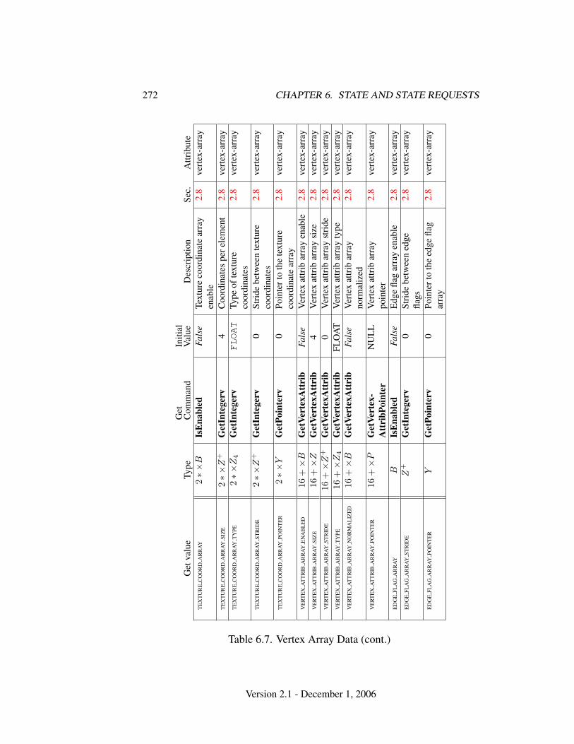
272 CHAPTER 6. STATE AND STATE REQUESTS
Get
valu
eTy
peG
etC
omm
and
Initi
alV
alue
Des
crip
tion
Sec.
Attr
ibut
eT
EX
TU
RE
CO
OR
DA
RR
AY
2∗×
BIs
Ena
bled
Fals
eTe
xtur
eco
ordi
nate
arra
yen
able
2.8
vert
ex-a
rray
TE
XT
UR
EC
OO
RD
AR
RA
YSI
ZE
2∗×
Z+
Get
Inte
gerv
4C
oord
inat
espe
rele
men
t2.
8ve
rtex
-arr
ayT
EX
TU
RE
CO
OR
DA
RR
AY
TY
PE2∗×
Z4
Get
Inte
gerv
FLOAT
Type
ofte
xtur
eco
ordi
nate
s2.
8ve
rtex
-arr
ay
TE
XT
UR
EC
OO
RD
AR
RA
YST
RID
E2∗×
Z+
Get
Inte
gerv
0St
ride
betw
een
text
ure
coor
dina
tes
2.8
vert
ex-a
rray
TE
XT
UR
EC
OO
RD
AR
RA
YPO
INT
ER
2∗×
YG
etPo
inte
rv0
Poin
tert
oth
ete
xtur
eco
ordi
nate
arra
y2.
8ve
rtex
-arr
ay
VE
RT
EX
AT
TR
IBA
RR
AY
EN
AB
LE
D16
+×
BG
etVe
rtex
Att
rib
Fals
eV
erte
xat
trib
arra
yen
able
2.8
vert
ex-a
rray
VE
RT
EX
AT
TR
IBA
RR
AY
SIZ
E16
+×
ZG
etVe
rtex
Att
rib
4V
erte
xat
trib
arra
ysi
ze2.
8ve
rtex
-arr
ayV
ER
TE
XA
TT
RIB
AR
RA
YST
RID
E16
+×
Z+
Get
Vert
exA
ttri
b0
Ver
tex
attr
ibar
ray
stri
de2.
8ve
rtex
-arr
ayV
ER
TE
XA
TT
RIB
AR
RA
YT
YPE
16+×
Z4
Get
Vert
exA
ttri
bFL
OA
TV
erte
xat
trib
arra
yty
pe2.
8ve
rtex
-arr
ayV
ER
TE
XA
TT
RIB
AR
RA
YN
OR
MA
LIZ
ED
16+×
BG
etVe
rtex
Att
rib
Fals
eV
erte
xat
trib
arra
yno
rmal
ized
2.8
vert
ex-a
rray
VE
RT
EX
AT
TR
IBA
RR
AY
POIN
TE
R16
+×
PG
etVe
rtex
-A
ttri
bPoi
nter
NU
LL
Ver
tex
attr
ibar
ray
poin
ter
2.8
vert
ex-a
rray
ED
GE
FLA
GA
RR
AY
BIs
Ena
bled
Fals
eE
dge
flag
arra
yen
able
2.8
vert
ex-a
rray
ED
GE
FLA
GA
RR
AY
STR
IDE
Z+
Get
Inte
gerv
0St
ride
betw
een
edge
flags
2.8
vert
ex-a
rray
ED
GE
FLA
GA
RR
AY
POIN
TE
RY
Get
Poin
terv
0Po
inte
rto
the
edge
flag
arra
y2.
8ve
rtex
-arr
ay
Table 6.7. Vertex Array Data (cont.)
Version 2.1 - December 1, 2006
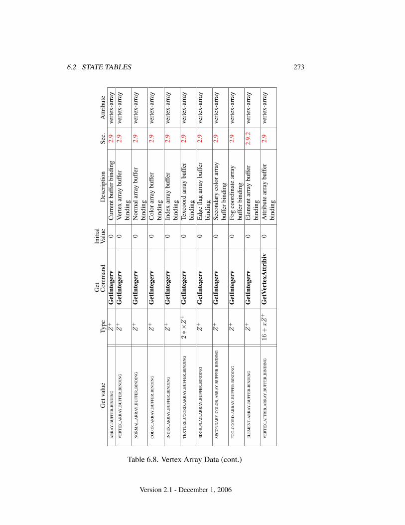
6.2. STATE TABLES 273
Get
valu
eTy
peG
etC
omm
and
Initi
alV
alue
Des
crip
tion
Sec.
Attr
ibut
eA
RR
AY
BU
FFE
RB
IND
ING
Z+
Get
Inte
gerv
0C
urre
ntbu
ffer
bind
ing
2.9
vert
ex-a
rray
VE
RT
EX
AR
RA
YB
UFF
ER
BIN
DIN
GZ
+G
etIn
tege
rv0
Ver
tex
arra
ybu
ffer
bind
ing
2.9
vert
ex-a
rray
NO
RM
AL
AR
RA
YB
UFF
ER
BIN
DIN
GZ
+G
etIn
tege
rv0
Nor
mal
arra
ybu
ffer
bind
ing
2.9
vert
ex-a
rray
CO
LO
RA
RR
AY
BU
FFE
RB
IND
ING
Z+
Get
Inte
gerv
0C
olor
arra
ybu
ffer
bind
ing
2.9
vert
ex-a
rray
IND
EX
AR
RA
YB
UFF
ER
BIN
DIN
GZ
+G
etIn
tege
rv0
Inde
xar
ray
buff
erbi
ndin
g2.
9ve
rtex
-arr
ay
TE
XT
UR
EC
OO
RD
AR
RA
YB
UFF
ER
BIN
DIN
G2∗×
Z+
Get
Inte
gerv
0Te
xcoo
rdar
ray
buff
erbi
ndin
g2.
9ve
rtex
-arr
ay
ED
GE
FLA
GA
RR
AY
BU
FFE
RB
IND
ING
Z+
Get
Inte
gerv
0E
dge
flag
arra
ybu
ffer
bind
ing
2.9
vert
ex-a
rray
SEC
ON
DA
RYC
OL
OR
AR
RA
YB
UFF
ER
BIN
DIN
GZ
+G
etIn
tege
rv0
Seco
ndar
yco
lora
rray
buff
erbi
ndin
g2.
9ve
rtex
-arr
ay
FOG
CO
OR
DA
RR
AY
BU
FFE
RB
IND
ING
Z+
Get
Inte
gerv
0Fo
gco
ordi
nate
arra
ybu
ffer
bind
ing
2.9
vert
ex-a
rray
EL
EM
EN
TA
RR
AY
BU
FFE
RB
IND
ING
Z+
Get
Inte
gerv
0E
lem
enta
rray
buff
erbi
ndin
g2.
9.2
vert
ex-a
rray
VE
RT
EX
AT
TR
IBA
RR
AY
BU
FFE
RB
IND
ING
16+
xZ
+G
etVe
rtex
Att
ribi
v0
Attr
ibut
ear
ray
buff
erbi
ndin
g2.
9ve
rtex
-arr
ay
Table 6.8. Vertex Array Data (cont.)
Version 2.1 - December 1, 2006
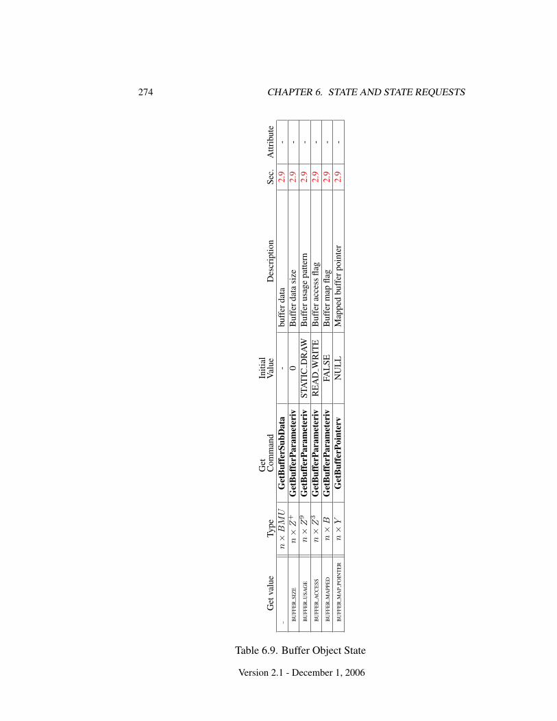
274 CHAPTER 6. STATE AND STATE REQUESTS
Get
valu
eTy
peG
etC
omm
and
Initi
alV
alue
Des
crip
tion
Sec.
Attr
ibut
e–
n×
BM
UG
etB
uffe
rSub
Dat
a-
buff
erda
ta2.
9-
BU
FFE
RSI
ZE
n×
Z+
Get
Buf
ferP
aram
eter
iv0
Buf
ferd
ata
size
2.9
-B
UFF
ER
USA
GE
n×
Z9
Get
Buf
ferP
aram
eter
ivST
AT
ICD
RA
WB
uffe
rusa
gepa
ttern
2.9
-B
UFF
ER
AC
CE
SSn×
Z3
Get
Buf
ferP
aram
eter
ivR
EA
DW
RIT
EB
uffe
racc
ess
flag
2.9
-B
UFF
ER
MA
PPE
Dn×
BG
etB
uffe
rPar
amet
eriv
FAL
SEB
uffe
rmap
flag
2.9
-B
UFF
ER
MA
PPO
INT
ER
n×
YG
etB
uffe
rPoi
nter
vN
UL
LM
appe
dbu
ffer
poin
ter
2.9
-
Table 6.9. Buffer Object State
Version 2.1 - December 1, 2006
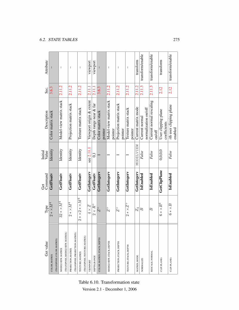
6.2. STATE TABLES 275
Get
valu
eTy
peG
etC
omm
and
Initi
alV
alue
Des
crip
tion
Sec.
Attr
ibut
eC
OL
OR
MA
TR
IX
(TR
AN
SPO
SEC
OL
OR
MA
TR
IX)
2∗×
M4
Get
Floa
tvId
entit
yC
olor
mat
rix
stac
k3.
6.3
–
MO
DE
LVIE
WM
AT
RIX
(TR
AN
SPO
SEM
OD
ELV
IEW
MA
TR
IX)
32∗×
M4
Get
Floa
tvId
entit
yM
odel
-vie
wm
atri
xst
ack
2.11
.2–
PRO
JEC
TIO
NM
AT
RIX
(TR
AN
SPO
SEPR
OJE
CT
ION
MA
TR
IX)
2∗×
M4
Get
Floa
tvId
entit
yPr
ojec
tion
mat
rix
stac
k2.
11.2
–
TE
XT
UR
EM
AT
RIX
(TR
AN
SPO
SET
EX
TU
RE
MA
TR
IX)
2∗×
2∗×
M4
Get
Floa
tvId
entit
yTe
xtur
em
atri
xst
ack
2.11
.2–
VIE
WPO
RT
4×
ZG
etIn
tege
rvse
e2.
11.1
Vie
wpo
rtor
igin
&ex
tent
2.11
.1vi
ewpo
rtD
EPT
HR
AN
GE
2×
R+
Get
Floa
tv0,
1D
epth
rang
ene
ar&
far
2.11
.1vi
ewpo
rtC
OL
OR
MA
TR
IXST
AC
KD
EPT
HZ
+G
etIn
tege
rv1
Col
orm
atri
xst
ack
poin
ter
3.6.
3–
MO
DE
LVIE
WST
AC
KD
EPT
HZ
+G
etIn
tege
rv1
Mod
el-v
iew
mat
rix
stac
kpo
inte
r2.
11.2
–
PRO
JEC
TIO
NST
AC
KD
EPT
HZ
+G
etIn
tege
rv1
Proj
ectio
nm
atri
xst
ack
poin
ter
2.11
.2–
TE
XT
UR
EST
AC
KD
EPT
H2∗×
Z+
Get
Inte
gerv
1Te
xtur
em
atri
xst
ack
poin
ter
2.11
.2–
MA
TR
IXM
OD
EZ
4G
etIn
tege
rvMODELVIEW
Cur
rent
mat
rix
mod
e2.
11.2
tran
sfor
mN
OR
MA
LIZ
EB
IsE
nabl
edFa
lse
Cur
rent
norm
alno
rmal
izat
ion
on/o
ff2.
11.3
tran
sfor
m/e
nabl
e
RE
SCA
LE
NO
RM
AL
BIs
Ena
bled
Fals
eC
urre
ntno
rmal
resc
alin
gon
/off
2.11
.3tr
ansf
orm
/ena
ble
CL
IPPL
AN
Ei
6∗×
R4
Get
Clip
Plan
e0,
0,0,
0U
serc
lippi
ngpl
ane
coef
ficie
nts
2.12
tran
sfor
m
CL
IPPL
AN
Ei
6∗×
BIs
Ena
bled
Fals
eit
hus
ercl
ippi
ngpl
ane
enab
led
2.12
tran
sfor
m/e
nabl
e
Table 6.10. Transformation stateVersion 2.1 - December 1, 2006
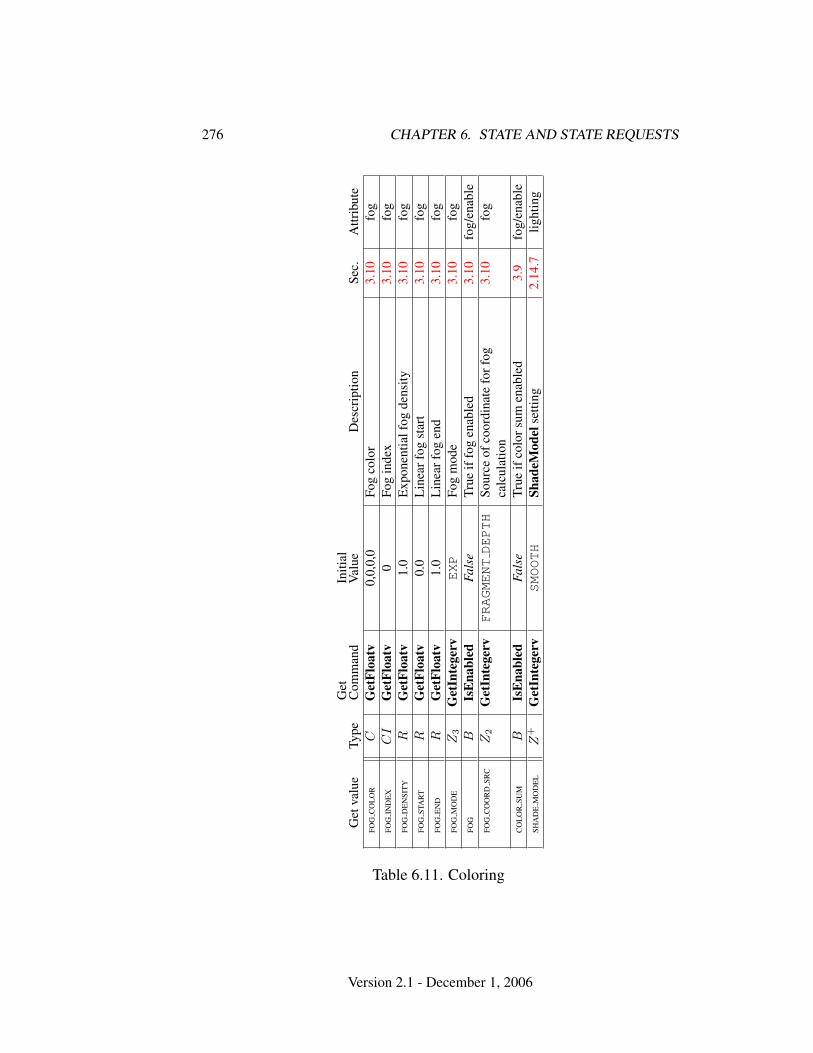
276 CHAPTER 6. STATE AND STATE REQUESTS
Get
valu
eTy
peG
etC
omm
and
Initi
alV
alue
Des
crip
tion
Sec.
Attr
ibut
eFO
GC
OL
OR
CG
etFl
oatv
0,0,
0,0
Fog
colo
r3.
10fo
gFO
GIN
DE
XC
IG
etFl
oatv
0Fo
gin
dex
3.10
fog
FOG
DE
NSI
TY
RG
etFl
oatv
1.0
Exp
onen
tialf
ogde
nsity
3.10
fog
FOG
STA
RT
RG
etFl
oatv
0.0
Lin
earf
ogst
art
3.10
fog
FOG
EN
DR
Get
Floa
tv1.
0L
inea
rfog
end
3.10
fog
FOG
MO
DE
Z3
Get
Inte
gerv
EXP
Fog
mod
e3.
10fo
gFO
GB
IsE
nabl
edFa
lse
True
iffo
gen
able
d3.
10fo
g/en
able
FOG
CO
OR
DSR
CZ
2G
etIn
tege
rvFRAGMENTDEPTH
Sour
ceof
coor
dina
tefo
rfog
calc
ulat
ion
3.10
fog
CO
LO
RSU
MB
IsE
nabl
edFa
lse
True
ifco
lors
umen
able
d3.
9fo
g/en
able
SHA
DE
MO
DE
LZ
+G
etIn
tege
rvSMOOTH
Shad
eMod
else
tting
2.14
.7lig
htin
g
Table 6.11. Coloring
Version 2.1 - December 1, 2006
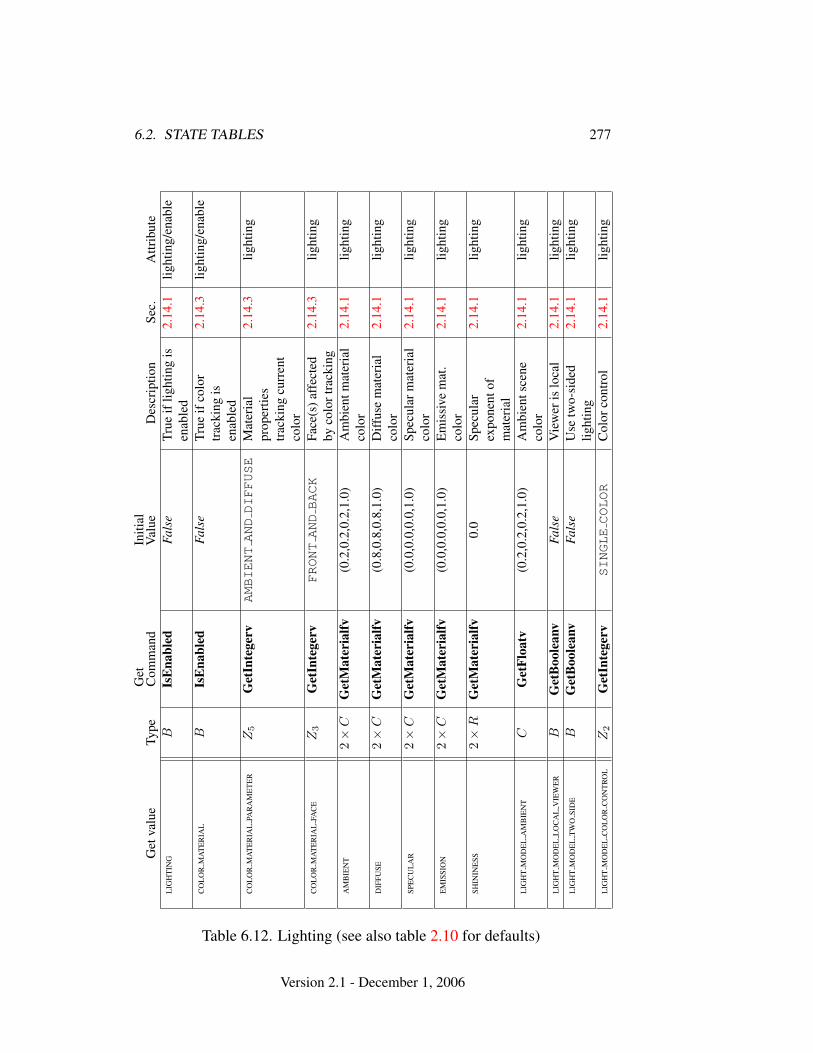
6.2. STATE TABLES 277G
etva
lue
Type
Get
Com
man
dIn
itial
Val
ueD
escr
iptio
nSe
c.A
ttrib
ute
LIG
HT
ING
BIs
Ena
bled
Fals
eTr
ueif
light
ing
isen
able
d2.
14.1
light
ing/
enab
le
CO
LO
RM
AT
ER
IAL
BIs
Ena
bled
Fals
eTr
ueif
colo
rtr
acki
ngis
enab
led
2.14
.3lig
htin
g/en
able
CO
LO
RM
AT
ER
IAL
PAR
AM
ET
ER
Z5
Get
Inte
gerv
AMBIENTANDDIFFUSE
Mat
eria
lpr
oper
ties
trac
king
curr
ent
colo
r
2.14
.3lig
htin
g
CO
LO
RM
AT
ER
IAL
FAC
EZ
3G
etIn
tege
rvFRONTANDBACK
Face
(s)a
ffec
ted
byco
lort
rack
ing
2.14
.3lig
htin
g
AM
BIE
NT
2×
CG
etM
ater
ialfv
(0.2
,0.2
,0.2
,1.0
)A
mbi
entm
ater
ial
colo
r2.
14.1
light
ing
DIF
FUSE
2×
CG
etM
ater
ialfv
(0.8
,0.8
,0.8
,1.0
)D
iffus
em
ater
ial
colo
r2.
14.1
light
ing
SPE
CU
LA
R2×
CG
etM
ater
ialfv
(0.0
,0.0
,0.0
,1.0
)Sp
ecul
arm
ater
ial
colo
r2.
14.1
light
ing
EM
ISSI
ON
2×
CG
etM
ater
ialfv
(0.0
,0.0
,0.0
,1.0
)E
mis
sive
mat
.co
lor
2.14
.1lig
htin
g
SHIN
INE
SS2×
RG
etM
ater
ialfv
0.0
Spec
ular
expo
nent
ofm
ater
ial
2.14
.1lig
htin
g
LIG
HT
MO
DE
LA
MB
IEN
TC
Get
Floa
tv(0
.2,0
.2,0
.2,1
.0)
Am
bien
tsce
neco
lor
2.14
.1lig
htin
g
LIG
HT
MO
DE
LL
OC
AL
VIE
WE
RB
Get
Boo
lean
vFa
lse
Vie
wer
islo
cal
2.14
.1lig
htin
gL
IGH
TM
OD
EL
TW
OSI
DE
BG
etB
oole
anv
Fals
eU
setw
o-si
ded
light
ing
2.14
.1lig
htin
g
LIG
HT
MO
DE
LC
OL
OR
CO
NT
RO
LZ
2G
etIn
tege
rvSINGLECOLOR
Col
orco
ntro
l2.
14.1
light
ing
Table 6.12. Lighting (see also table 2.10 for defaults)
Version 2.1 - December 1, 2006
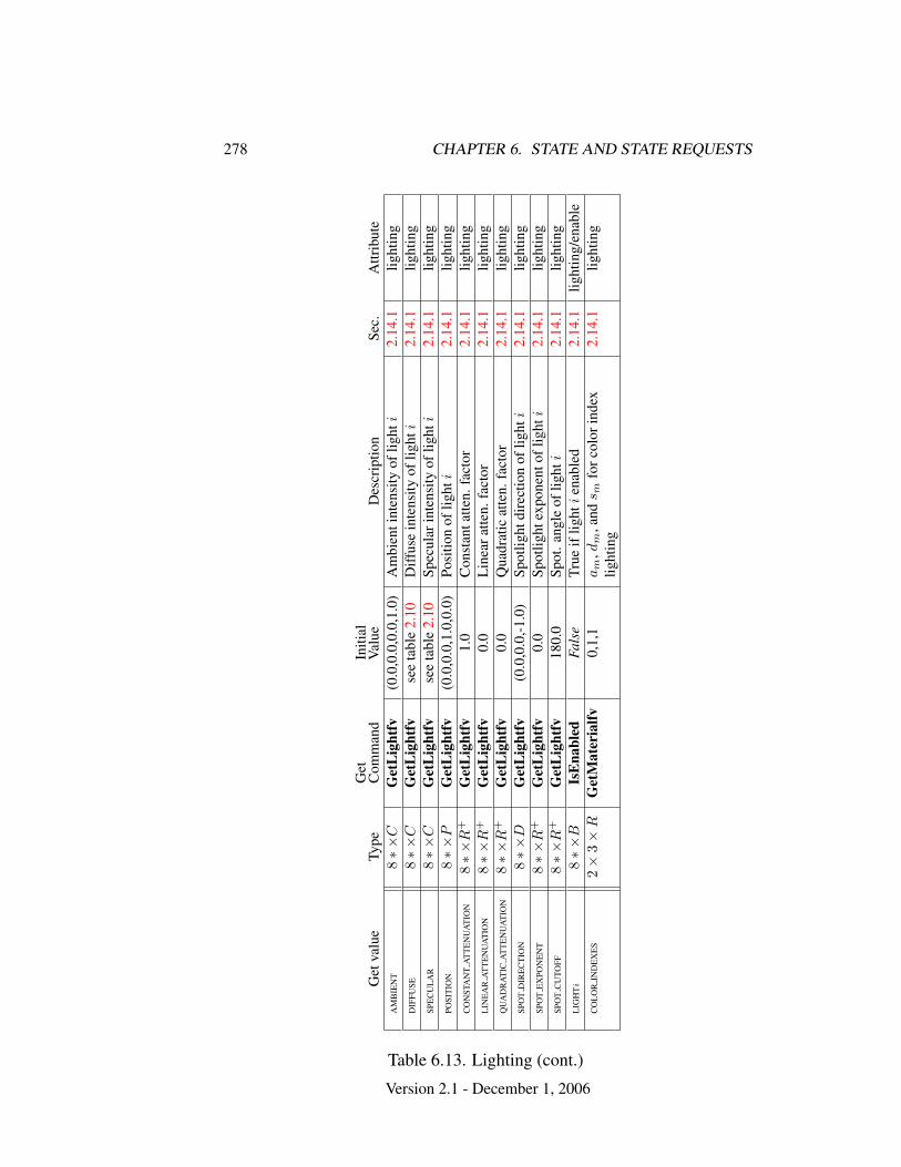
278 CHAPTER 6. STATE AND STATE REQUESTS
Get
valu
eTy
peG
etC
omm
and
Initi
alV
alue
Des
crip
tion
Sec.
Attr
ibut
eA
MB
IEN
T8∗×
CG
etL
ight
fv(0
.0,0
.0,0
.0,1
.0)
Am
bien
tint
ensi
tyof
light
i2.
14.1
light
ing
DIF
FUSE
8∗×
CG
etL
ight
fvse
eta
ble
2.10
Diff
use
inte
nsity
oflig
hti
2.14
.1lig
htin
gSP
EC
UL
AR
8∗×
CG
etL
ight
fvse
eta
ble
2.10
Spec
ular
inte
nsity
oflig
hti
2.14
.1lig
htin
gPO
SIT
ION
8∗×
PG
etL
ight
fv(0
.0,0
.0,1
.0,0
.0)
Posi
tion
oflig
hti
2.14
.1lig
htin
gC
ON
STA
NT
AT
TE
NU
AT
ION
8∗×
R+
Get
Lig
htfv
1.0
Con
stan
tatte
n.fa
ctor
2.14
.1lig
htin
gL
INE
AR
AT
TE
NU
AT
ION
8∗×
R+
Get
Lig
htfv
0.0
Lin
eara
tten.
fact
or2.
14.1
light
ing
QU
AD
RA
TIC
AT
TE
NU
AT
ION
8∗×
R+
Get
Lig
htfv
0.0
Qua
drat
icat
ten.
fact
or2.
14.1
light
ing
SPO
TD
IRE
CT
ION
8∗×
DG
etL
ight
fv(0
.0,0
.0,-1
.0)
Spot
light
dire
ctio
nof
light
i2.
14.1
light
ing
SPO
TE
XPO
NE
NT
8∗×
R+
Get
Lig
htfv
0.0
Spot
light
expo
nent
oflig
hti
2.14
.1lig
htin
gSP
OT
CU
TOFF
8∗×
R+
Get
Lig
htfv
180.
0Sp
ot.a
ngle
oflig
hti
2.14
.1lig
htin
gL
IGH
Ti
8∗×
BIs
Ena
bled
Fals
eTr
ueif
light
ien
able
d2.
14.1
light
ing/
enab
leC
OL
OR
IND
EX
ES
2×
3×
RG
etM
ater
ialfv
0,1,
1a
m,d
m,a
nds m
forc
olor
inde
xlig
htin
g2.
14.1
light
ing
Table 6.13. Lighting (cont.)
Version 2.1 - December 1, 2006
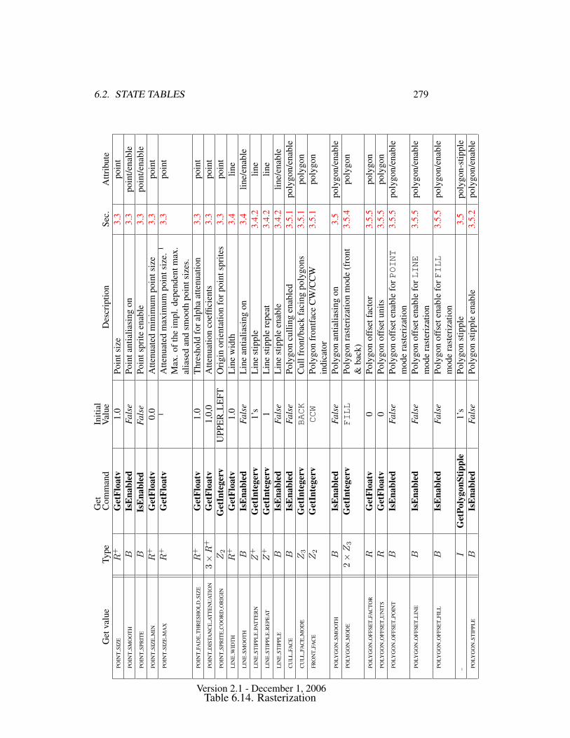
6.2. STATE TABLES 279G
etva
lue
Type
Get
Com
man
dIn
itial
Val
ueD
escr
iptio
nSe
c.A
ttrib
ute
POIN
TSI
ZE
R+
Get
Floa
tv1.
0Po
ints
ize
3.3
poin
tPO
INT
SMO
OT
HB
IsE
nabl
edFa
lse
Poin
tant
ialia
sing
on3.
3po
int/e
nabl
ePO
INT
SPR
ITE
BIs
Ena
bled
Fals
ePo
ints
prite
enab
le3.
3po
int/e
nabl
ePO
INT
SIZ
EM
INR
+G
etFl
oatv
0.0
Atte
nuat
edm
inim
umpo
ints
ize
3.3
poin
tPO
INT
SIZ
EM
AX
R+
Get
Floa
tv1
Atte
nuat
edm
axim
umpo
ints
ize.
1
Max
.oft
heim
pl.d
epen
dent
max
.al
iase
dan
dsm
ooth
poin
tsiz
es.
3.3
poin
t
POIN
TFA
DE
TH
RE
SHO
LD
SIZ
ER
+G
etFl
oatv
1.0
Thr
esho
ldfo
ralp
haat
tenu
atio
n3.
3po
int
POIN
TD
ISTA
NC
EA
TT
EN
UA
TIO
N3×
R+
Get
Floa
tv1,
0,0
Atte
nuat
ion
coef
ficie
nts
3.3
poin
tPO
INT
SPR
ITE
CO
OR
DO
RIG
INZ
2G
etIn
tege
rvU
PPE
RL
EFT
Ori
gin
orie
ntat
ion
forp
oint
spri
tes
3.3
poin
tL
INE
WID
TH
R+
Get
Floa
tv1.
0L
ine
wid
th3.
4lin
eL
INE
SMO
OT
HB
IsE
nabl
edFa
lse
Lin
ean
tialia
sing
on3.
4lin
e/en
able
LIN
EST
IPPL
EPA
TT
ER
NZ
+G
etIn
tege
rv1’
sL
ine
stip
ple
3.4.
2lin
eL
INE
STIP
PLE
RE
PEA
TZ
+G
etIn
tege
rv1
Lin
est
ippl
ere
peat
3.4.
2lin
eL
INE
STIP
PLE
BIs
Ena
bled
Fals
eL
ine
stip
ple
enab
le3.
4.2
line/
enab
leC
UL
LFA
CE
BIs
Ena
bled
Fals
ePo
lygo
ncu
lling
enab
led
3.5.
1po
lygo
n/en
able
CU
LL
FAC
EM
OD
EZ
3G
etIn
tege
rvBACK
Cul
lfro
nt/b
ack
faci
ngpo
lygo
ns3.
5.1
poly
gon
FRO
NT
FAC
EZ
2G
etIn
tege
rvCCW
Poly
gon
fron
tface
CW
/CC
Win
dica
tor
3.5.
1po
lygo
n
POLY
GO
NSM
OO
TH
BIs
Ena
bled
Fals
ePo
lygo
nan
tialia
sing
on3.
5po
lygo
n/en
able
POLY
GO
NM
OD
E2×
Z3
Get
Inte
gerv
FILL
Poly
gon
rast
eriz
atio
nm
ode
(fro
nt&
back
)3.
5.4
poly
gon
POLY
GO
NO
FFSE
TFA
CTO
RR
Get
Floa
tv0
Poly
gon
offs
etfa
ctor
3.5.
5po
lygo
nPO
LYG
ON
OFF
SET
UN
ITS
RG
etFl
oatv
0Po
lygo
nof
fset
units
3.5.
5po
lygo
nPO
LYG
ON
OFF
SET
POIN
TB
IsE
nabl
edFa
lse
Poly
gon
offs
eten
able
forPOINT
mod
era
ster
izat
ion
3.5.
5po
lygo
n/en
able
POLY
GO
NO
FFSE
TL
INE
BIs
Ena
bled
Fals
ePo
lygo
nof
fset
enab
lefo
rLINE
mod
era
ster
izat
ion
3.5.
5po
lygo
n/en
able
POLY
GO
NO
FFSE
TFI
LL
BIs
Ena
bled
Fals
ePo
lygo
nof
fset
enab
lefo
rFILL
mod
era
ster
izat
ion
3.5.
5po
lygo
n/en
able
–I
Get
Poly
gonS
tippl
e1’
sPo
lygo
nst
ippl
e3.
5po
lygo
n-st
ippl
ePO
LYG
ON
STIP
PLE
BIs
Ena
bled
Fals
ePo
lygo
nst
ippl
een
able
3.5.
2po
lygo
n/en
able
Table 6.14. RasterizationVersion 2.1 - December 1, 2006

280 CHAPTER 6. STATE AND STATE REQUESTS
Get
valu
eTy
peG
etC
omm
and
Initi
alV
alue
Des
crip
tion
Sec.
Attr
ibut
eM
ULT
ISA
MPL
EB
IsE
nabl
edTr
ueM
ultis
ampl
era
ster
izat
ion
3.2.
1m
ultis
ampl
e/en
able
SAM
PLE
AL
PHA
TOC
OV
ER
AG
EB
IsE
nabl
edFa
lse
Mod
ify
cove
rage
from
alph
a4.
1.3
mul
tisam
ple/
enab
leSA
MPL
EA
LPH
ATO
ON
EB
IsE
nabl
edFa
lse
Seta
lpha
tom
axim
um4.
1.3
mul
tisam
ple/
enab
leSA
MPL
EC
OV
ER
AG
EB
IsE
nabl
edFa
lse
Mas
kto
mod
ify
cove
rage
4.1.
3m
ultis
ampl
e/en
able
SAM
PLE
CO
VE
RA
GE
VAL
UE
R+
Get
Floa
tv1
Cov
erag
em
ask
valu
e4.
1.3
mul
tisam
ple
SAM
PLE
CO
VE
RA
GE
INV
ER
TB
Get
Boo
lean
vFa
lse
Inve
rtco
vera
gem
ask
valu
e4.
1.3
mul
tisam
ple
Table 6.15. Multisampling
Version 2.1 - December 1, 2006
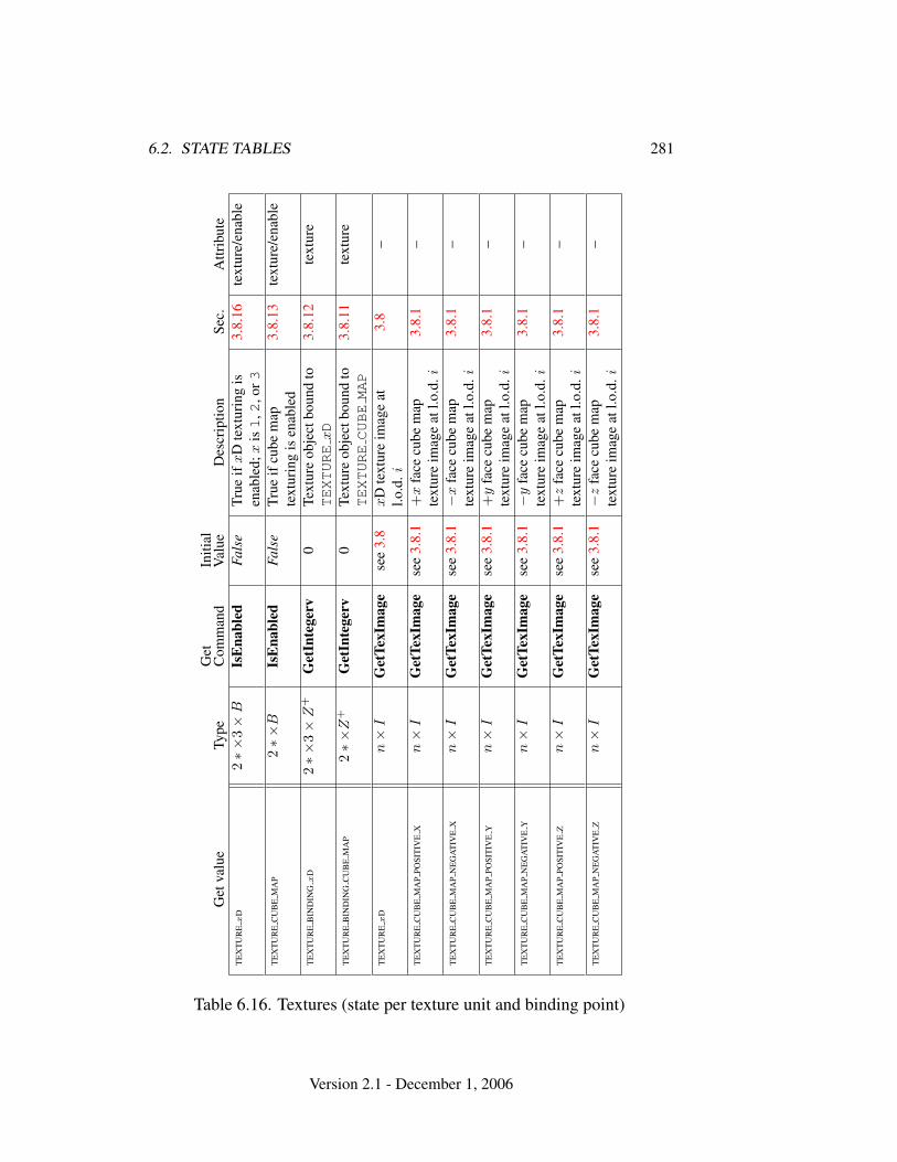
6.2. STATE TABLES 281
Get
valu
eTy
peG
etC
omm
and
Initi
alV
alue
Des
crip
tion
Sec.
Attr
ibut
eT
EX
TU
RE
xD
2∗×
3×
BIs
Ena
bled
Fals
eTr
ueif
xD
text
urin
gis
enab
led;
xis1
,2,o
r33.
8.16
text
ure/
enab
le
TE
XT
UR
EC
UB
EM
AP
2∗×
BIs
Ena
bled
Fals
eTr
ueif
cube
map
text
urin
gis
enab
led
3.8.
13te
xtur
e/en
able
TE
XT
UR
EB
IND
ING
xD
2∗×
3×
Z+
Get
Inte
gerv
0Te
xtur
eob
ject
boun
dto
TEXTURE
xD
3.8.
12te
xtur
e
TE
XT
UR
EB
IND
ING
CU
BE
MA
P2∗×
Z+
Get
Inte
gerv
0Te
xtur
eob
ject
boun
dto
TEXTURECUBEMAP
3.8.
11te
xtur
e
TE
XT
UR
Ex
Dn×
IG
etTe
xIm
age
see
3.8
xD
text
ure
imag
eat
l.o.d
.i3.
8–
TE
XT
UR
EC
UB
EM
AP
POSI
TIV
EX
n×
IG
etTe
xIm
age
see
3.8.
1+
xfa
cecu
bem
apte
xtur
eim
age
atl.o
.d.i
3.8.
1–
TE
XT
UR
EC
UB
EM
AP
NE
GA
TIV
EX
n×
IG
etTe
xIm
age
see
3.8.
1−
xfa
cecu
bem
apte
xtur
eim
age
atl.o
.d.i
3.8.
1–
TE
XT
UR
EC
UB
EM
AP
POSI
TIV
EY
n×
IG
etTe
xIm
age
see
3.8.
1+
yfa
cecu
bem
apte
xtur
eim
age
atl.o
.d.i
3.8.
1–
TE
XT
UR
EC
UB
EM
AP
NE
GA
TIV
EY
n×
IG
etTe
xIm
age
see
3.8.
1−
yfa
cecu
bem
apte
xtur
eim
age
atl.o
.d.i
3.8.
1–
TE
XT
UR
EC
UB
EM
AP
POSI
TIV
EZ
n×
IG
etTe
xIm
age
see
3.8.
1+
zfa
cecu
bem
apte
xtur
eim
age
atl.o
.d.i
3.8.
1–
TE
XT
UR
EC
UB
EM
AP
NE
GA
TIV
EZ
n×
IG
etTe
xIm
age
see
3.8.
1−
zfa
cecu
bem
apte
xtur
eim
age
atl.o
.d.i
3.8.
1–
Table 6.16. Textures (state per texture unit and binding point)
Version 2.1 - December 1, 2006
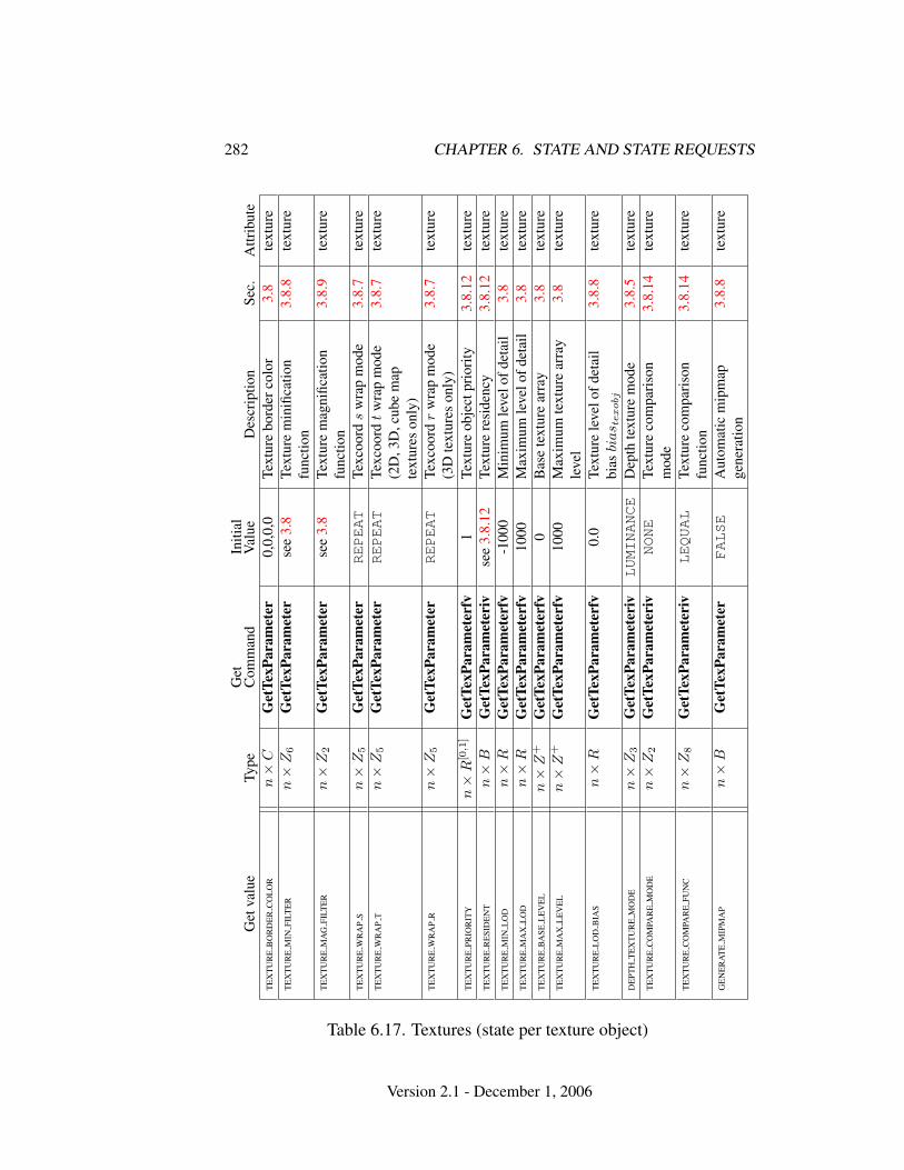
282 CHAPTER 6. STATE AND STATE REQUESTS
Get
valu
eTy
peG
etC
omm
and
Initi
alV
alue
Des
crip
tion
Sec.
Attr
ibut
eT
EX
TU
RE
BO
RD
ER
CO
LO
Rn×
CG
etTe
xPar
amet
er0,
0,0,
0Te
xtur
ebo
rder
colo
r3.
8te
xtur
eT
EX
TU
RE
MIN
FILT
ER
n×
Z6
Get
TexP
aram
eter
see
3.8
Text
ure
min
ifica
tion
func
tion
3.8.
8te
xtur
e
TE
XT
UR
EM
AG
FILT
ER
n×
Z2
Get
TexP
aram
eter
see
3.8
Text
ure
mag
nific
atio
nfu
nctio
n3.
8.9
text
ure
TE
XT
UR
EW
RA
PS
n×
Z5
Get
TexP
aram
eter
REPEAT
Texc
oord
sw
rap
mod
e3.
8.7
text
ure
TE
XT
UR
EW
RA
PT
n×
Z5
Get
TexP
aram
eter
REPEAT
Texc
oord
tw
rap
mod
e(2
D,3
D,c
ube
map
text
ures
only
)
3.8.
7te
xtur
e
TE
XT
UR
EW
RA
PR
n×
Z5
Get
TexP
aram
eter
REPEAT
Texc
oord
rw
rap
mod
e(3
Dte
xtur
eson
ly)
3.8.
7te
xtur
e
TE
XT
UR
EPR
IOR
ITY
n×
R[0
,1]
Get
TexP
aram
eter
fv1
Text
ure
obje
ctpr
iori
ty3.
8.12
text
ure
TE
XT
UR
ER
ESI
DE
NT
n×
BG
etTe
xPar
amet
eriv
see
3.8.
12Te
xtur
ere
side
ncy
3.8.
12te
xtur
eT
EX
TU
RE
MIN
LO
Dn×
RG
etTe
xPar
amet
erfv
-100
0M
inim
umle
velo
fdet
ail
3.8
text
ure
TE
XT
UR
EM
AX
LO
Dn×
RG
etTe
xPar
amet
erfv
1000
Max
imum
leve
lofd
etai
l3.
8te
xtur
eT
EX
TU
RE
BA
SEL
EV
EL
n×
Z+
Get
TexP
aram
eter
fv0
Bas
ete
xtur
ear
ray
3.8
text
ure
TE
XT
UR
EM
AX
LE
VE
Ln×
Z+
Get
TexP
aram
eter
fv10
00M
axim
umte
xtur
ear
ray
leve
l3.
8te
xtur
e
TE
XT
UR
EL
OD
BIA
Sn×
RG
etTe
xPar
amet
erfv
0.0
Text
ure
leve
lofd
etai
lbi
asbi
as t
exobj
3.8.
8te
xtur
e
DE
PTH
TE
XT
UR
EM
OD
En×
Z3
Get
TexP
aram
eter
ivLUMINANCE
Dep
thte
xtur
em
ode
3.8.
5te
xtur
eT
EX
TU
RE
CO
MPA
RE
MO
DE
n×
Z2
Get
TexP
aram
eter
ivNONE
Text
ure
com
pari
son
mod
e3.
8.14
text
ure
TE
XT
UR
EC
OM
PAR
EFU
NC
n×
Z8
Get
TexP
aram
eter
ivLEQUAL
Text
ure
com
pari
son
func
tion
3.8.
14te
xtur
e
GE
NE
RA
TE
MIP
MA
Pn×
BG
etTe
xPar
amet
erFALSE
Aut
omat
icm
ipm
apge
nera
tion
3.8.
8te
xtur
e
Table 6.17. Textures (state per texture object)
Version 2.1 - December 1, 2006
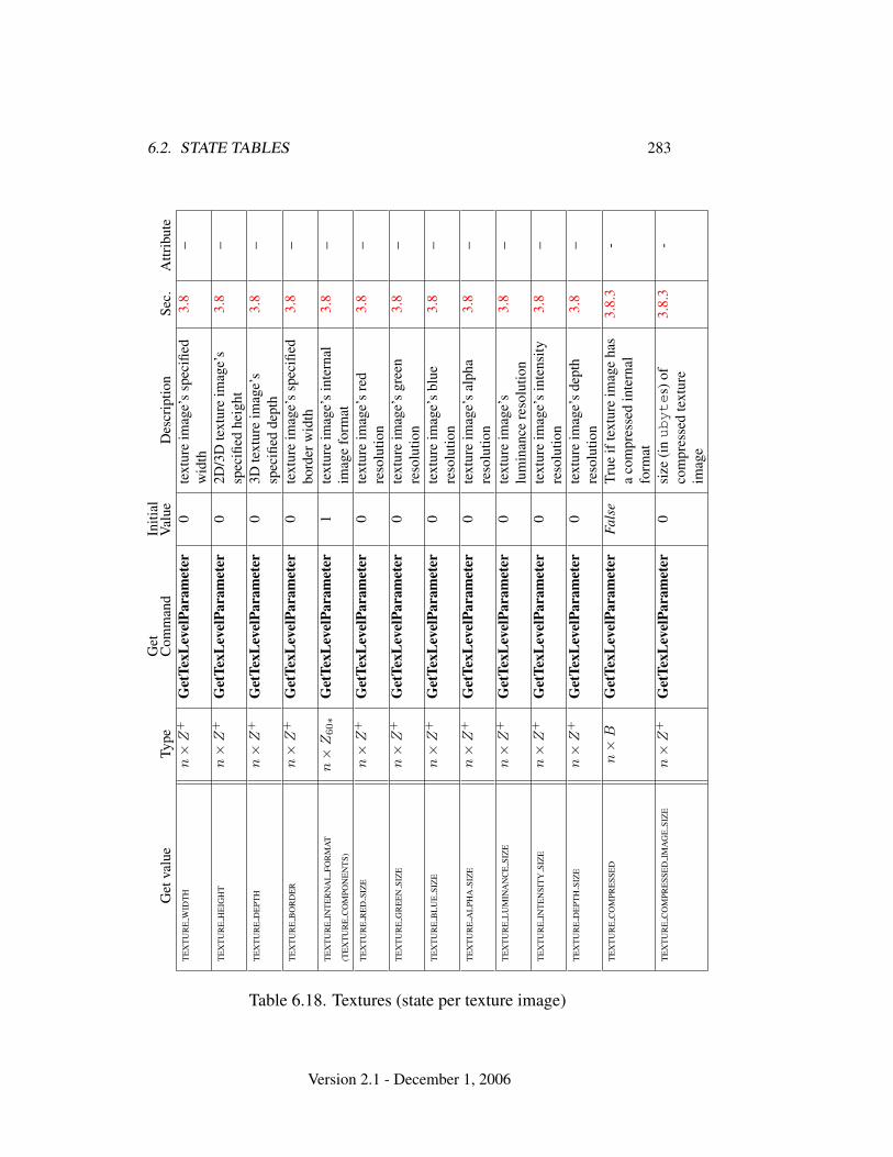
6.2. STATE TABLES 283G
etva
lue
Type
Get
Com
man
dIn
itial
Val
ueD
escr
iptio
nSe
c.A
ttrib
ute
TE
XT
UR
EW
IDT
Hn×
Z+
Get
TexL
evel
Para
met
er0
text
ure
imag
e’s
spec
ified
wid
th3.
8–
TE
XT
UR
EH
EIG
HT
n×
Z+
Get
TexL
evel
Para
met
er0
2D/3
Dte
xtur
eim
age’
ssp
ecifi
edhe
ight
3.8
–
TE
XT
UR
ED
EPT
Hn×
Z+
Get
TexL
evel
Para
met
er0
3Dte
xtur
eim
age’
ssp
ecifi
edde
pth
3.8
–
TE
XT
UR
EB
OR
DE
Rn×
Z+
Get
TexL
evel
Para
met
er0
text
ure
imag
e’s
spec
ified
bord
erw
idth
3.8
–
TE
XT
UR
EIN
TE
RN
AL
FOR
MA
T
(TE
XT
UR
EC
OM
PON
EN
TS)
n×
Z60∗
Get
TexL
evel
Para
met
er1
text
ure
imag
e’s
inte
rnal
imag
efo
rmat
3.8
–
TE
XT
UR
ER
ED
SIZ
En×
Z+
Get
TexL
evel
Para
met
er0
text
ure
imag
e’s
red
reso
lutio
n3.
8–
TE
XT
UR
EG
RE
EN
SIZ
En×
Z+
Get
TexL
evel
Para
met
er0
text
ure
imag
e’s
gree
nre
solu
tion
3.8
–
TE
XT
UR
EB
LU
ESI
ZE
n×
Z+
Get
TexL
evel
Para
met
er0
text
ure
imag
e’s
blue
reso
lutio
n3.
8–
TE
XT
UR
EA
LPH
ASI
ZE
n×
Z+
Get
TexL
evel
Para
met
er0
text
ure
imag
e’s
alph
are
solu
tion
3.8
–
TE
XT
UR
EL
UM
INA
NC
ESI
ZE
n×
Z+
Get
TexL
evel
Para
met
er0
text
ure
imag
e’s
lum
inan
cere
solu
tion
3.8
–
TE
XT
UR
EIN
TE
NSI
TY
SIZ
En×
Z+
Get
TexL
evel
Para
met
er0
text
ure
imag
e’s
inte
nsity
reso
lutio
n3.
8–
TE
XT
UR
ED
EPT
HSI
ZE
n×
Z+
Get
TexL
evel
Para
met
er0
text
ure
imag
e’s
dept
hre
solu
tion
3.8
–
TE
XT
UR
EC
OM
PRE
SSE
Dn×
BG
etTe
xLev
elPa
ram
eter
Fals
eTr
ueif
text
ure
imag
eha
sa
com
pres
sed
inte
rnal
form
at
3.8.
3-
TE
XT
UR
EC
OM
PRE
SSE
DIM
AG
ESI
ZE
n×
Z+
Get
TexL
evel
Para
met
er0
size
(inubyte
s)of
com
pres
sed
text
ure
imag
e
3.8.
3-
Table 6.18. Textures (state per texture image)
Version 2.1 - December 1, 2006
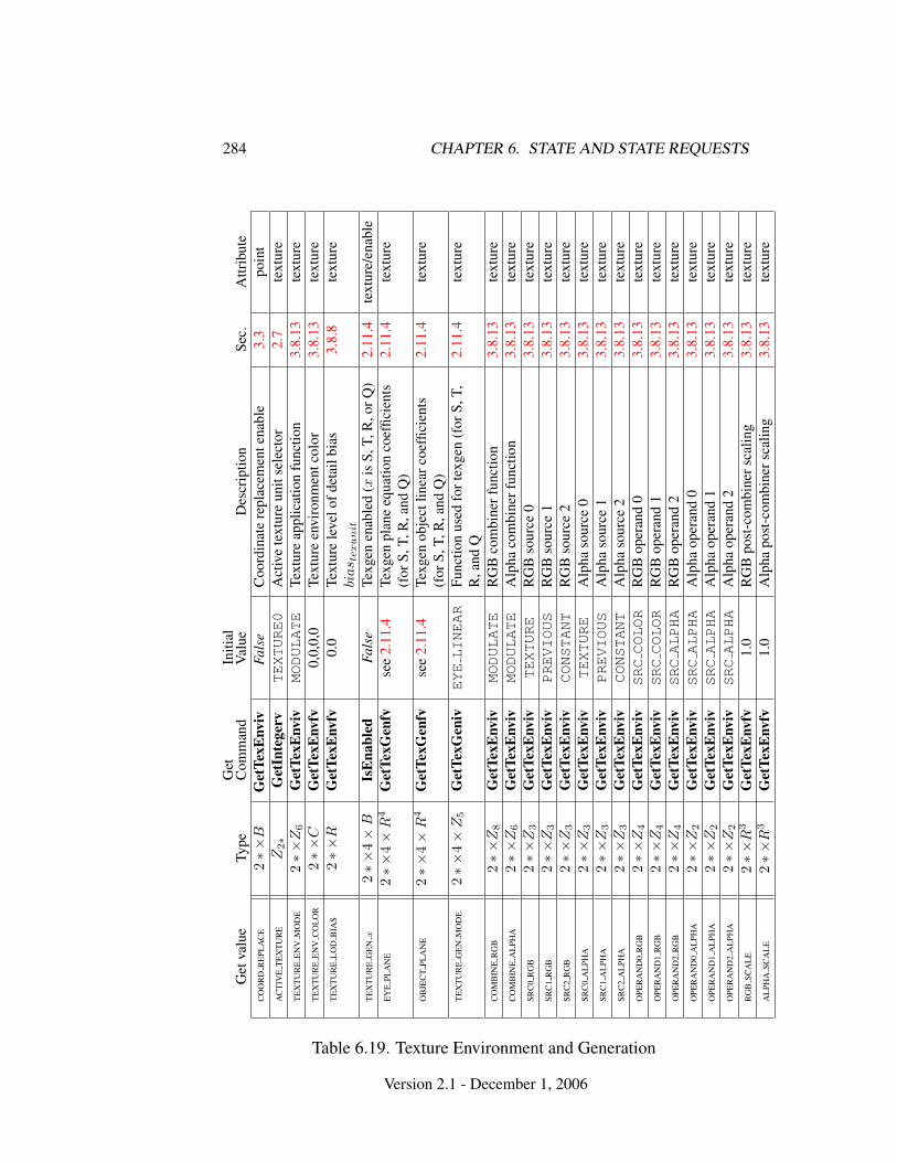
284 CHAPTER 6. STATE AND STATE REQUESTS
Get
valu
eTy
peG
etC
omm
and
Initi
alV
alue
Des
crip
tion
Sec.
Attr
ibut
eC
OO
RD
RE
PLA
CE
2∗×
BG
etTe
xEnv
ivFa
lse
Coo
rdin
ate
repl
acem
ente
nabl
e3.
3po
int
AC
TIV
ET
EX
TU
RE
Z2∗
Get
Inte
gerv
TEXTURE0
Act
ive
text
ure
unit
sele
ctor
2.7
text
ure
TE
XT
UR
EE
NV
MO
DE
2∗×
Z6
Get
TexE
nviv
MODULATE
Text
ure
appl
icat
ion
func
tion
3.8.
13te
xtur
eT
EX
TU
RE
EN
VC
OL
OR
2∗×
CG
etTe
xEnv
fv0,
0,0,
0Te
xtur
een
viro
nmen
tcol
or3.
8.13
text
ure
TE
XT
UR
EL
OD
BIA
S2∗×
RG
etTe
xEnv
fv0.
0Te
xtur
ele
velo
fdet
ailb
ias
bias t
exu
nit
3.8.
8te
xtur
e
TE
XT
UR
EG
EN
x2∗×
4×
BIs
Ena
bled
Fals
eTe
xgen
enab
led
(xis
S,T,
R,o
rQ)
2.11
.4te
xtur
e/en
able
EY
EPL
AN
E2∗×
4×
R4
Get
TexG
enfv
see
2.11
.4Te
xgen
plan
eeq
uatio
nco
effic
ient
s(f
orS,
T,R
,and
Q)
2.11
.4te
xtur
e
OB
JEC
TPL
AN
E2∗×
4×
R4
Get
TexG
enfv
see
2.11
.4Te
xgen
obje
ctlin
earc
oeffi
cien
ts(f
orS,
T,R
,and
Q)
2.11
.4te
xtur
e
TE
XT
UR
EG
EN
MO
DE
2∗×
4×
Z5
Get
TexG
eniv
EYELINEAR
Func
tion
used
fort
exge
n(f
orS,
T,R
,and
Q2.
11.4
text
ure
CO
MB
INE
RG
B2∗×
Z8
Get
TexE
nviv
MODULATE
RG
Bco
mbi
nerf
unct
ion
3.8.
13te
xtur
eC
OM
BIN
EA
LPH
A2∗×
Z6
Get
TexE
nviv
MODULATE
Alp
haco
mbi
nerf
unct
ion
3.8.
13te
xtur
eSR
C0
RG
B2∗×
Z3
Get
TexE
nviv
TEXTURE
RG
Bso
urce
03.
8.13
text
ure
SRC
1R
GB
2∗×
Z3
Get
TexE
nviv
PREVIOUS
RG
Bso
urce
13.
8.13
text
ure
SRC
2R
GB
2∗×
Z3
Get
TexE
nviv
CONSTANT
RG
Bso
urce
23.
8.13
text
ure
SRC
0A
LPH
A2∗×
Z3
Get
TexE
nviv
TEXTURE
Alp
haso
urce
03.
8.13
text
ure
SRC
1A
LPH
A2∗×
Z3
Get
TexE
nviv
PREVIOUS
Alp
haso
urce
13.
8.13
text
ure
SRC
2A
LPH
A2∗×
Z3
Get
TexE
nviv
CONSTANT
Alp
haso
urce
23.
8.13
text
ure
OPE
RA
ND
0R
GB
2∗×
Z4
Get
TexE
nviv
SRCCOLOR
RG
Bop
eran
d0
3.8.
13te
xtur
eO
PER
AN
D1
RG
B2∗×
Z4
Get
TexE
nviv
SRCCOLOR
RG
Bop
eran
d1
3.8.
13te
xtur
eO
PER
AN
D2
RG
B2∗×
Z4
Get
TexE
nviv
SRCALPHA
RG
Bop
eran
d2
3.8.
13te
xtur
eO
PER
AN
D0
AL
PHA
2∗×
Z2
Get
TexE
nviv
SRCALPHA
Alp
haop
eran
d0
3.8.
13te
xtur
eO
PER
AN
D1
AL
PHA
2∗×
Z2
Get
TexE
nviv
SRCALPHA
Alp
haop
eran
d1
3.8.
13te
xtur
eO
PER
AN
D2
AL
PHA
2∗×
Z2
Get
TexE
nviv
SRCALPHA
Alp
haop
eran
d2
3.8.
13te
xtur
eR
GB
SCA
LE
2∗×
R3
Get
TexE
nvfv
1.0
RG
Bpo
st-c
ombi
ners
calin
g3.
8.13
text
ure
AL
PHA
SCA
LE
2∗×
R3
Get
TexE
nvfv
1.0
Alp
hapo
st-c
ombi
ners
calin
g3.
8.13
text
ure
Table 6.19. Texture Environment and Generation
Version 2.1 - December 1, 2006
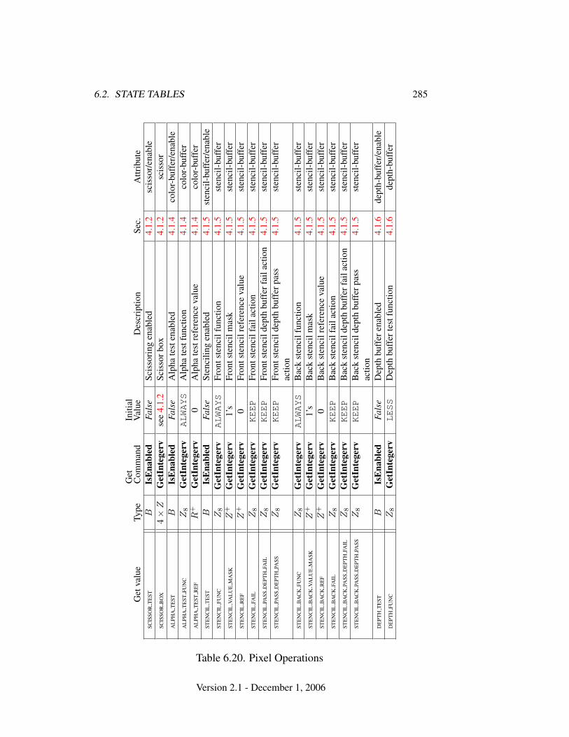
6.2. STATE TABLES 285
Get
valu
eTy
peG
etC
omm
and
Initi
alV
alue
Des
crip
tion
Sec.
Attr
ibut
eSC
ISSO
RT
EST
BIs
Ena
bled
Fals
eSc
isso
ring
enab
led
4.1.
2sc
isso
r/en
able
SCIS
SOR
BO
X4×
ZG
etIn
tege
rvse
e4.
1.2
Scis
sorb
ox4.
1.2
scis
sor
AL
PHA
TE
STB
IsE
nabl
edFa
lse
Alp
hate
sten
able
d4.
1.4
colo
r-bu
ffer
/ena
ble
AL
PHA
TE
STFU
NC
Z8
Get
Inte
gerv
ALWAYS
Alp
hate
stfu
nctio
n4.
1.4
colo
r-bu
ffer
AL
PHA
TE
STR
EF
R+
Get
Inte
gerv
0A
lpha
test
refe
renc
eva
lue
4.1.
4co
lor-
buff
erST
EN
CIL
TE
STB
IsE
nabl
edFa
lse
Sten
cilin
gen
able
d4.
1.5
sten
cil-
buff
er/e
nabl
eST
EN
CIL
FUN
CZ
8G
etIn
tege
rvALWAYS
Fron
tste
ncil
func
tion
4.1.
5st
enci
l-bu
ffer
STE
NC
ILVA
LU
EM
ASK
Z+
Get
Inte
gerv
1’s
Fron
tste
ncil
mas
k4.
1.5
sten
cil-
buff
erST
EN
CIL
RE
FZ
+G
etIn
tege
rv0
Fron
tste
ncil
refe
renc
eva
lue
4.1.
5st
enci
l-bu
ffer
STE
NC
ILFA
ILZ
8G
etIn
tege
rvKEEP
Fron
tste
ncil
fail
actio
n4.
1.5
sten
cil-
buff
erST
EN
CIL
PASS
DE
PTH
FAIL
Z8
Get
Inte
gerv
KEEP
Fron
tste
ncil
dept
hbu
ffer
fail
actio
n4.
1.5
sten
cil-
buff
erST
EN
CIL
PASS
DE
PTH
PASS
Z8
Get
Inte
gerv
KEEP
Fron
tste
ncil
dept
hbu
ffer
pass
actio
n4.
1.5
sten
cil-
buff
er
STE
NC
ILB
AC
KFU
NC
Z8
Get
Inte
gerv
ALWAYS
Bac
kst
enci
lfun
ctio
n4.
1.5
sten
cil-
buff
erST
EN
CIL
BA
CK
VAL
UE
MA
SKZ
+G
etIn
tege
rv1’
sB
ack
sten
cilm
ask
4.1.
5st
enci
l-bu
ffer
STE
NC
ILB
AC
KR
EF
Z+
Get
Inte
gerv
0B
ack
sten
cilr
efer
ence
valu
e4.
1.5
sten
cil-
buff
erST
EN
CIL
BA
CK
FAIL
Z8
Get
Inte
gerv
KEEP
Bac
kst
enci
lfai
lact
ion
4.1.
5st
enci
l-bu
ffer
STE
NC
ILB
AC
KPA
SSD
EPT
HFA
ILZ
8G
etIn
tege
rvKEEP
Bac
kst
enci
ldep
thbu
ffer
fail
actio
n4.
1.5
sten
cil-
buff
erST
EN
CIL
BA
CK
PASS
DE
PTH
PASS
Z8
Get
Inte
gerv
KEEP
Bac
kst
enci
ldep
thbu
ffer
pass
actio
n4.
1.5
sten
cil-
buff
er
DE
PTH
TE
STB
IsE
nabl
edFa
lse
Dep
thbu
ffer
enab
led
4.1.
6de
pth-
buff
er/e
nabl
eD
EPT
HFU
NC
Z8
Get
Inte
gerv
LESS
Dep
thbu
ffer
test
func
tion
4.1.
6de
pth-
buff
er
Table 6.20. Pixel Operations
Version 2.1 - December 1, 2006
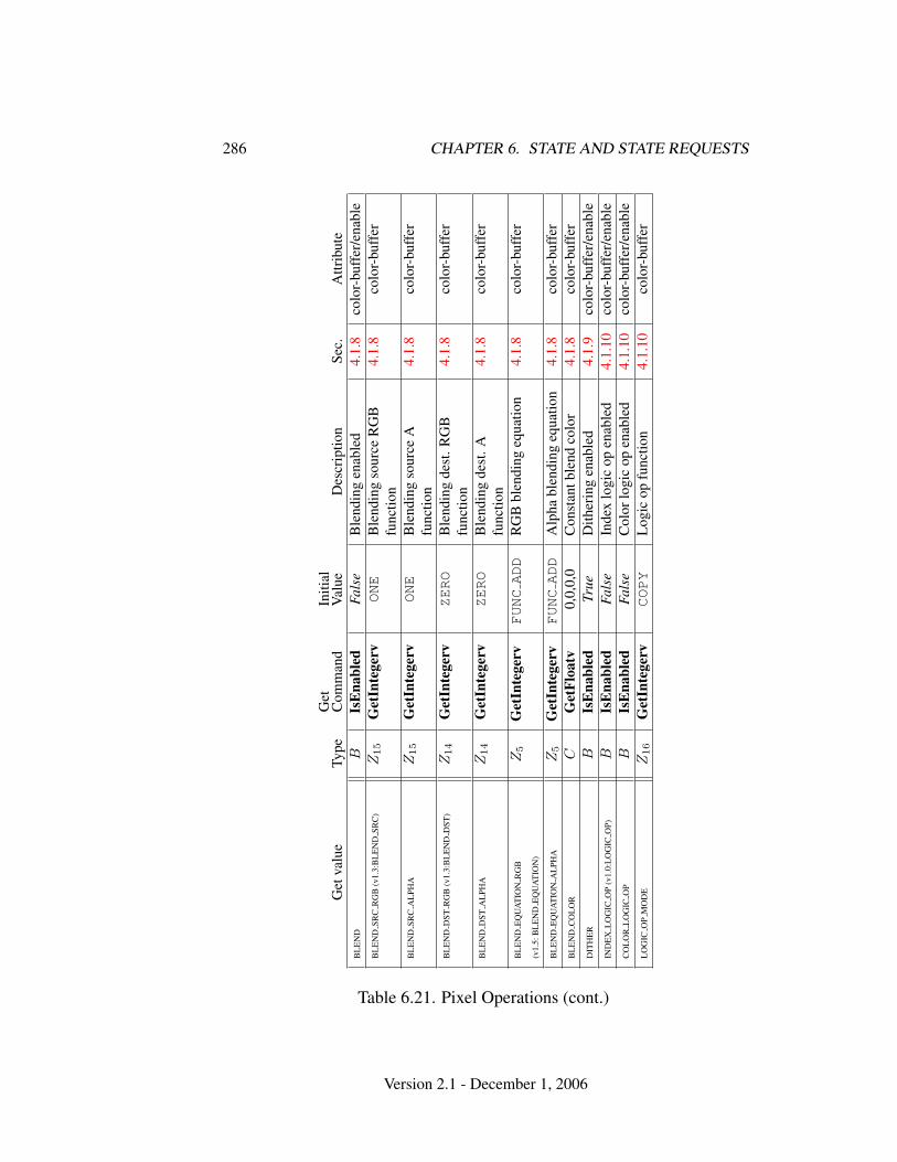
286 CHAPTER 6. STATE AND STATE REQUESTS
Get
valu
eTy
peG
etC
omm
and
Initi
alV
alue
Des
crip
tion
Sec.
Attr
ibut
eB
LE
ND
BIs
Ena
bled
Fals
eB
lend
ing
enab
led
4.1.
8co
lor-
buff
er/e
nabl
eB
LE
ND
SRC
RG
B(v
1.3:
BL
EN
DSR
C)
Z15
Get
Inte
gerv
ONE
Ble
ndin
gso
urce
RG
Bfu
nctio
n4.
1.8
colo
r-bu
ffer
BL
EN
DSR
CA
LPH
AZ
15
Get
Inte
gerv
ONE
Ble
ndin
gso
urce
Afu
nctio
n4.
1.8
colo
r-bu
ffer
BL
EN
DD
STR
GB
(v1.
3:B
LE
ND
DST
)Z
14
Get
Inte
gerv
ZERO
Ble
ndin
gde
st.R
GB
func
tion
4.1.
8co
lor-
buff
er
BL
EN
DD
STA
LPH
AZ
14
Get
Inte
gerv
ZERO
Ble
ndin
gde
st.A
func
tion
4.1.
8co
lor-
buff
er
BL
EN
DE
QU
AT
ION
RG
B
(v1.
5:B
LE
ND
EQ
UA
TIO
N)
Z5
Get
Inte
gerv
FUNCADD
RG
Bbl
endi
ngeq
uatio
n4.
1.8
colo
r-bu
ffer
BL
EN
DE
QU
AT
ION
AL
PHA
Z5
Get
Inte
gerv
FUNCADD
Alp
habl
endi
ngeq
uatio
n4.
1.8
colo
r-bu
ffer
BL
EN
DC
OL
OR
CG
etFl
oatv
0,0,
0,0
Con
stan
tble
ndco
lor
4.1.
8co
lor-
buff
erD
ITH
ER
BIs
Ena
bled
True
Dith
erin
gen
able
d4.
1.9
colo
r-bu
ffer
/ena
ble
IND
EX
LO
GIC
OP
(v1.
0:L
OG
ICO
P)B
IsE
nabl
edFa
lse
Inde
xlo
gic
open
able
d4.
1.10
colo
r-bu
ffer
/ena
ble
CO
LO
RL
OG
ICO
PB
IsE
nabl
edFa
lse
Col
orlo
gic
open
able
d4.
1.10
colo
r-bu
ffer
/ena
ble
LO
GIC
OP
MO
DE
Z16
Get
Inte
gerv
COPY
Log
icop
func
tion
4.1.
10co
lor-
buff
er
Table 6.21. Pixel Operations (cont.)
Version 2.1 - December 1, 2006
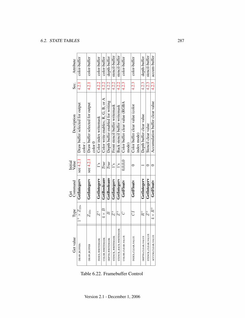
6.2. STATE TABLES 287
Get
valu
eTy
peG
etC
omm
and
Initi
alV
alue
Des
crip
tion
Sec.
Attr
ibut
eD
RA
WB
UFF
ER
i1+×
Z10∗
Get
Inte
gerv
see
4.2.
1D
raw
buff
erse
lect
edfo
rout
put
colo
ri4.
2.1
colo
r-bu
ffer
DR
AW
BU
FFE
RZ
10∗
Get
Inte
gerv
see
4.2.
1D
raw
buff
erse
lect
edfo
rout
put
colo
r04.
2.1
colo
r-bu
ffer
IND
EX
WR
ITE
MA
SKZ
+G
etIn
tege
rv1’
sC
olor
inde
xw
rite
mas
k4.
2.2
colo
r-bu
ffer
CO
LO
RW
RIT
EM
ASK
4×
BG
etB
oole
anv
True
Col
orw
rite
enab
les;
R,G
,B,o
rA4.
2.2
colo
r-bu
ffer
DE
PTH
WR
ITE
MA
SKB
Get
Boo
lean
vTr
ueD
epth
buff
eren
able
dfo
rwri
ting
4.2.
2de
pth-
buff
erST
EN
CIL
WR
ITE
MA
SKZ
+G
etIn
tege
rv1’
sFr
onts
tenc
ilbu
ffer
wri
tem
ask
4.2.
2st
enci
l-bu
ffer
STE
NC
ILB
AC
KW
RIT
EM
ASK
Z+
Get
Inte
gerv
1’s
Bac
kst
enci
lbuf
ferw
rite
mas
k4.
2.2
sten
cil-
buff
erC
OL
OR
CL
EA
RVA
LU
EC
Get
Floa
tv0,
0,0,
0C
olor
buff
ercl
earv
alue
(RG
BA
mod
e)4.
2.3
colo
r-bu
ffer
IND
EX
CL
EA
RVA
LU
EC
IG
etFl
oatv
0C
olor
buff
ercl
earv
alue
(col
orin
dex
mod
e)4.
2.3
colo
r-bu
ffer
DE
PTH
CL
EA
RVA
LU
ER
+G
etIn
tege
rv1
Dep
thbu
ffer
clea
rval
ue4.
2.3
dept
h-bu
ffer
STE
NC
ILC
LE
AR
VAL
UE
Z+
Get
Inte
gerv
0St
enci
lcle
arva
lue
4.2.
3st
enci
l-bu
ffer
AC
CU
MC
LE
AR
VAL
UE
4×
R+
Get
Floa
tv0
Acc
umul
atio
nbu
ffer
clea
rval
ue4.
2.3
accu
m-b
uffe
r
Table 6.22. Framebuffer Control
Version 2.1 - December 1, 2006
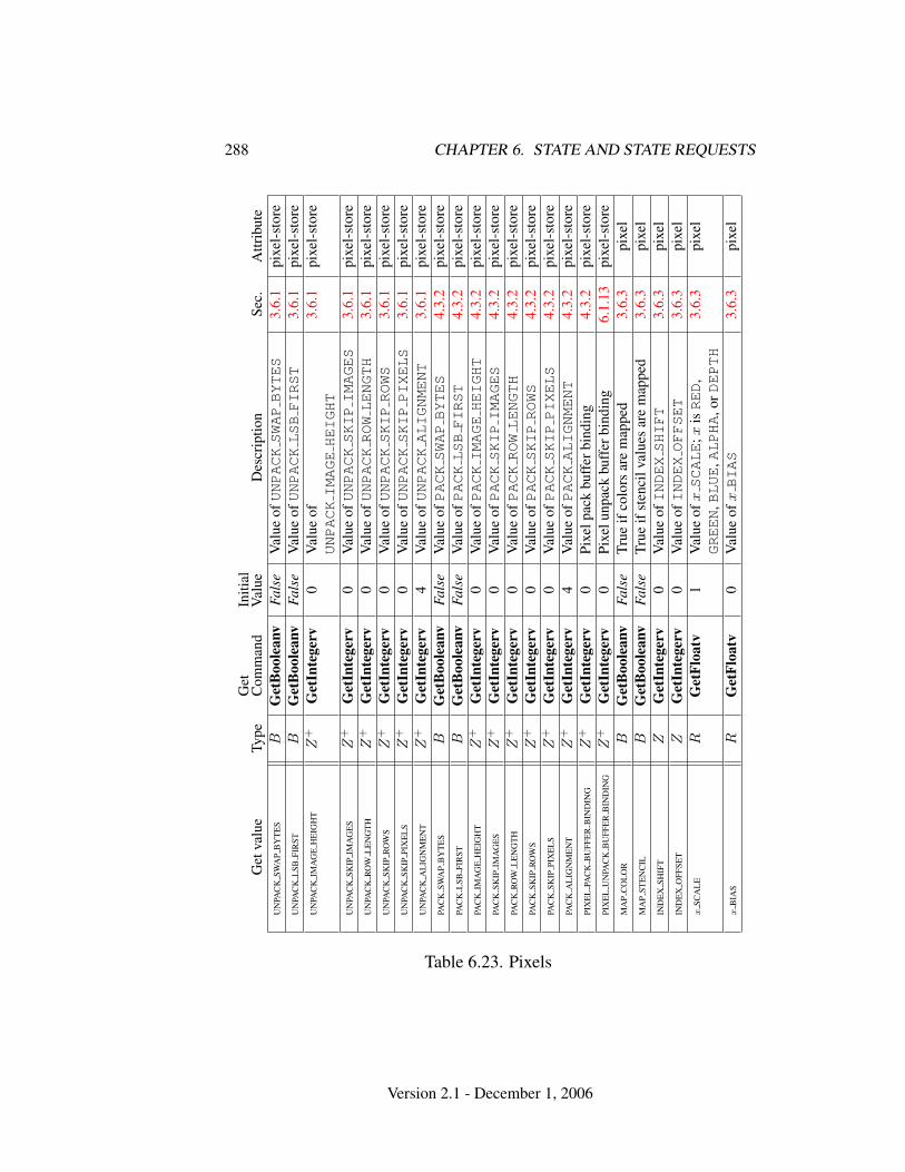
288 CHAPTER 6. STATE AND STATE REQUESTS
Get
valu
eTy
peG
etC
omm
and
Initi
alV
alue
Des
crip
tion
Sec.
Attr
ibut
eU
NPA
CK
SWA
PB
YT
ES
BG
etB
oole
anv
Fals
eV
alue
ofUNPACKSWAPBYTES
3.6.
1pi
xel-
stor
eU
NPA
CK
LSB
FIR
STB
Get
Boo
lean
vFa
lse
Val
ueofUNPACKLSBFIRST
3.6.
1pi
xel-
stor
eU
NPA
CK
IMA
GE
HE
IGH
TZ
+G
etIn
tege
rv0
Val
ueof
UNPACKIMAGEHEIGHT
3.6.
1pi
xel-
stor
e
UN
PAC
KSK
IPIM
AG
ES
Z+
Get
Inte
gerv
0V
alue
ofUNPACKSKIPIMAGES
3.6.
1pi
xel-
stor
eU
NPA
CK
RO
WL
EN
GT
HZ
+G
etIn
tege
rv0
Val
ueofUNPACKROWLENGTH
3.6.
1pi
xel-
stor
eU
NPA
CK
SKIP
RO
WS
Z+
Get
Inte
gerv
0V
alue
ofUNPACKSKIPROWS
3.6.
1pi
xel-
stor
eU
NPA
CK
SKIP
PIX
EL
SZ
+G
etIn
tege
rv0
Val
ueofUNPACKSKIPPIXELS
3.6.
1pi
xel-
stor
eU
NPA
CK
AL
IGN
ME
NT
Z+
Get
Inte
gerv
4V
alue
ofUNPACKALIGNMENT
3.6.
1pi
xel-
stor
ePA
CK
SWA
PB
YT
ES
BG
etB
oole
anv
Fals
eV
alue
ofPACKSWAPBYTES
4.3.
2pi
xel-
stor
ePA
CK
LSB
FIR
STB
Get
Boo
lean
vFa
lse
Val
ueofPACKLSBFIRST
4.3.
2pi
xel-
stor
ePA
CK
IMA
GE
HE
IGH
TZ
+G
etIn
tege
rv0
Val
ueofPACKIMAGEHEIGHT
4.3.
2pi
xel-
stor
ePA
CK
SKIP
IMA
GE
SZ
+G
etIn
tege
rv0
Val
ueofPACKSKIPIMAGES
4.3.
2pi
xel-
stor
ePA
CK
RO
WL
EN
GT
HZ
+G
etIn
tege
rv0
Val
ueofPACKROWLENGTH
4.3.
2pi
xel-
stor
ePA
CK
SKIP
RO
WS
Z+
Get
Inte
gerv
0V
alue
ofPACKSKIPROWS
4.3.
2pi
xel-
stor
ePA
CK
SKIP
PIX
EL
SZ
+G
etIn
tege
rv0
Val
ueofPACKSKIPPIXELS
4.3.
2pi
xel-
stor
ePA
CK
AL
IGN
ME
NT
Z+
Get
Inte
gerv
4V
alue
ofPACKALIGNMENT
4.3.
2pi
xel-
stor
ePI
XE
LPA
CK
BU
FFE
RB
IND
ING
Z+
Get
Inte
gerv
0Pi
xelp
ack
buff
erbi
ndin
g4.
3.2
pixe
l-st
ore
PIX
EL
UN
PAC
KB
UFF
ER
BIN
DIN
GZ
+G
etIn
tege
rv0
Pixe
lunp
ack
buff
erbi
ndin
g6.
1.13
pixe
l-st
ore
MA
PC
OL
OR
BG
etB
oole
anv
Fals
eTr
ueif
colo
rsar
em
appe
d3.
6.3
pixe
lM
AP
STE
NC
ILB
Get
Boo
lean
vFa
lse
True
ifst
enci
lval
ues
are
map
ped
3.6.
3pi
xel
IND
EX
SHIF
TZ
Get
Inte
gerv
0V
alue
ofINDEXSHIFT
3.6.
3pi
xel
IND
EX
OFF
SET
ZG
etIn
tege
rv0
Val
ueofINDEXOFFSET
3.6.
3pi
xel
xSC
AL
ER
Get
Floa
tv1
Val
ueof
xSCALE
;xisRED
,GREEN
,BLUE
,ALPHA
,orDEPTH
3.6.
3pi
xel
xB
IAS
RG
etFl
oatv
0V
alue
ofxBIAS
3.6.
3pi
xel
Table 6.23. Pixels
Version 2.1 - December 1, 2006
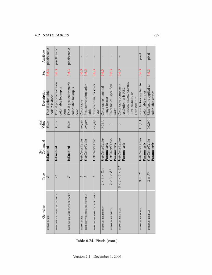
6.2. STATE TABLES 289
Get
valu
eTy
peG
etC
omm
and
Initi
alV
alue
Des
crip
tion
Sec.
Attr
ibut
eC
OL
OR
TAB
LE
BIs
Ena
bled
Fals
eTr
ueif
colo
rtab
lelo
okup
isdo
ne3.
6.3
pixe
l/ena
ble
POST
CO
NV
OL
UT
ION
CO
LO
RTA
BL
EB
IsE
nabl
edFa
lse
True
ifpo
stco
nvol
utio
nco
lort
able
look
upis
done
3.6.
3pi
xel/e
nabl
e
POST
CO
LO
RM
AT
RIX
CO
LO
RTA
BL
EB
IsE
nabl
edFa
lse
True
ifpo
stco
lorm
atri
xco
lort
able
look
upis
done
3.6.
3pi
xel/e
nabl
e
CO
LO
RTA
BL
EI
Get
Col
orTa
ble
empt
yC
olor
tabl
e3.
6.3
–PO
STC
ON
VO
LU
TIO
NC
OL
OR
TAB
LE
IG
etC
olor
Tabl
eem
pty
Post
conv
olut
ion
colo
rta
ble
3.6.
3–
POST
CO
LO
RM
AT
RIX
CO
LO
RTA
BL
EI
Get
Col
orTa
ble
empt
yPo
stco
lorm
atri
xco
lor
tabl
e3.
6.3
–
CO
LO
RTA
BL
EFO
RM
AT
2×
3×
Z42
Get
Col
orTa
ble-
Para
met
eriv
RGBA
Col
orta
bles
’int
erna
lim
age
form
at3.
6.3
–
CO
LO
RTA
BL
EW
IDT
H2×
3×
Z+
Get
Col
orTa
ble-
Para
met
eriv
0C
olor
tabl
es’s
peci
fied
wid
th3.
6.3
–
CO
LO
RTA
BL
Ex
SIZ
E6×
2×
3×
Z+
Get
Col
orTa
ble-
Para
met
eriv
0C
olor
tabl
eco
mpo
nent
reso
lutio
n;x
isRED
,GREEN
,BLUE
,ALPHA
,LUMINANCE
,or
INTENSITY
3.6.
3–
CO
LO
RTA
BL
ESC
AL
E3×
R4
Get
Col
orTa
ble-
Para
met
erfv
1,1,
1,1
Scal
efa
ctor
sap
plie
dto
colo
rtab
leen
trie
s3.
6.3
pixe
l
CO
LO
RTA
BL
EB
IAS
3×
R4
Get
Col
orTa
ble-
Para
met
erfv
0,0,
0,0
Bia
sfa
ctor
sap
plie
dto
colo
rtab
leen
trie
s3.
6.3
pixe
l
Table 6.24. Pixels (cont.)
Version 2.1 - December 1, 2006
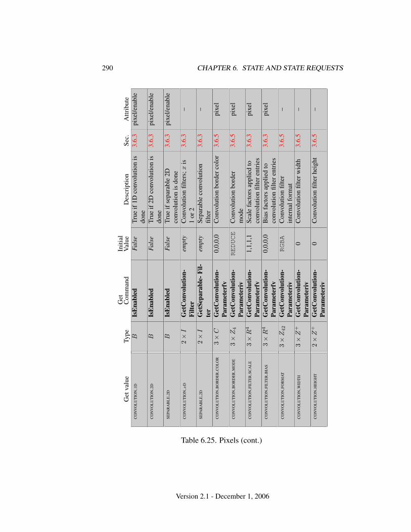
290 CHAPTER 6. STATE AND STATE REQUESTS
Get
valu
eTy
peG
etC
omm
and
Initi
alV
alue
Des
crip
tion
Sec.
Attr
ibut
eC
ON
VO
LU
TIO
N1D
BIs
Ena
bled
Fals
eTr
ueif
1Dco
nvol
utio
nis
done
3.6.
3pi
xel/e
nabl
e
CO
NV
OL
UT
ION
2DB
IsE
nabl
edFa
lse
True
if2D
conv
olut
ion
isdo
ne3.
6.3
pixe
l/ena
ble
SEPA
RA
BL
E2D
BIs
Ena
bled
Fals
eTr
ueif
sepa
rabl
e2D
conv
olut
ion
isdo
ne3.
6.3
pixe
l/ena
ble
CO
NV
OL
UT
ION
xD
2×
IG
etC
onvo
lutio
n-Fi
lter
empt
yC
onvo
lutio
nfil
ters
;xis
1or
23.
6.3
–
SEPA
RA
BL
E2D
2×
IG
etSe
para
ble-
Fil-
ter
empt
ySe
para
ble
conv
olut
ion
filte
r3.
6.3
–
CO
NV
OL
UT
ION
BO
RD
ER
CO
LO
R3×
CG
etC
onvo
lutio
n-Pa
ram
eter
fv0,
0,0,
0C
onvo
lutio
nbo
rder
colo
r3.
6.5
pixe
l
CO
NV
OL
UT
ION
BO
RD
ER
MO
DE
3×
Z4
Get
Con
volu
tion-
Para
met
eriv
REDUCE
Con
volu
tion
bord
erm
ode
3.6.
5pi
xel
CO
NV
OL
UT
ION
FILT
ER
SCA
LE
3×
R4
Get
Con
volu
tion-
Para
met
erfv
1,1,
1,1
Scal
efa
ctor
sap
plie
dto
conv
olut
ion
filte
rent
ries
3.6.
3pi
xel
CO
NV
OL
UT
ION
FILT
ER
BIA
S3×
R4
Get
Con
volu
tion-
Para
met
erfv
0,0,
0,0
Bia
sfa
ctor
sap
plie
dto
conv
olut
ion
filte
rent
ries
3.6.
3pi
xel
CO
NV
OL
UT
ION
FOR
MA
T3×
Z42
Get
Con
volu
tion-
Para
met
eriv
RGBA
Con
volu
tion
filte
rin
tern
alfo
rmat
3.6.
5–
CO
NV
OL
UT
ION
WID
TH
3×
Z+
Get
Con
volu
tion-
Para
met
eriv
0C
onvo
lutio
nfil
terw
idth
3.6.
5–
CO
NV
OL
UT
ION
HE
IGH
T2×
Z+
Get
Con
volu
tion-
Para
met
eriv
0C
onvo
lutio
nfil
terh
eigh
t3.
6.5
–
Table 6.25. Pixels (cont.)
Version 2.1 - December 1, 2006
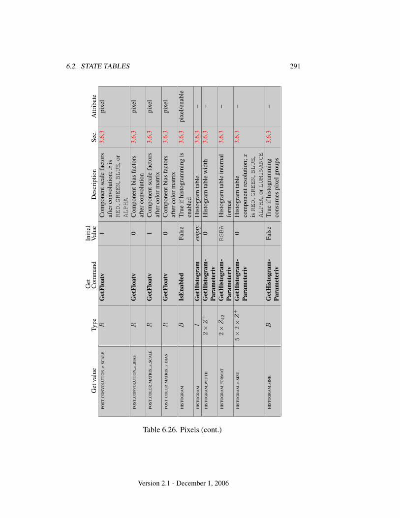
6.2. STATE TABLES 291
Get
valu
eTy
peG
etC
omm
and
Initi
alV
alue
Des
crip
tion
Sec.
Attr
ibut
ePO
STC
ON
VO
LU
TIO
Nx
SCA
LE
RG
etFl
oatv
1C
ompo
nent
scal
efa
ctor
saf
terc
onvo
lutio
n;x
isRED
,GREEN
,BLUE
,or
ALPHA
3.6.
3pi
xel
POST
CO
NV
OL
UT
ION
xB
IAS
RG
etFl
oatv
0C
ompo
nent
bias
fact
ors
afte
rcon
volu
tion
3.6.
3pi
xel
POST
CO
LO
RM
AT
RIX
xSC
AL
ER
Get
Floa
tv1
Com
pone
ntsc
ale
fact
ors
afte
rcol
orm
atri
x3.
6.3
pixe
l
POST
CO
LO
RM
AT
RIX
xB
IAS
RG
etFl
oatv
0C
ompo
nent
bias
fact
ors
afte
rcol
orm
atri
x3.
6.3
pixe
l
HIS
TOG
RA
MB
IsE
nabl
edFa
lse
True
ifhi
stog
ram
min
gis
enab
led
3.6.
3pi
xel/e
nabl
e
HIS
TOG
RA
MI
Get
His
togr
amem
pty
His
togr
amta
ble
3.6.
3–
HIS
TOG
RA
MW
IDT
H2×
Z+
Get
His
togr
am-
Para
met
eriv
0H
isto
gram
tabl
ew
idth
3.6.
3–
HIS
TOG
RA
MFO
RM
AT
2×
Z42
Get
His
togr
am-
Para
met
eriv
RGBA
His
togr
amta
ble
inte
rnal
form
at3.
6.3
–
HIS
TOG
RA
Mx
SIZ
E5×
2×
Z+
Get
His
togr
am-
Para
met
eriv
0H
isto
gram
tabl
eco
mpo
nent
reso
lutio
n;x
isRED
,GREEN
,BLUE
,ALPHA
,orLUMINANCE
3.6.
3–
HIS
TOG
RA
MSI
NK
BG
etH
isto
gram
-Pa
ram
eter
ivFa
lse
True
ifhi
stog
ram
min
gco
nsum
espi
xelg
roup
s3.
6.3
–
Table 6.26. Pixels (cont.)
Version 2.1 - December 1, 2006
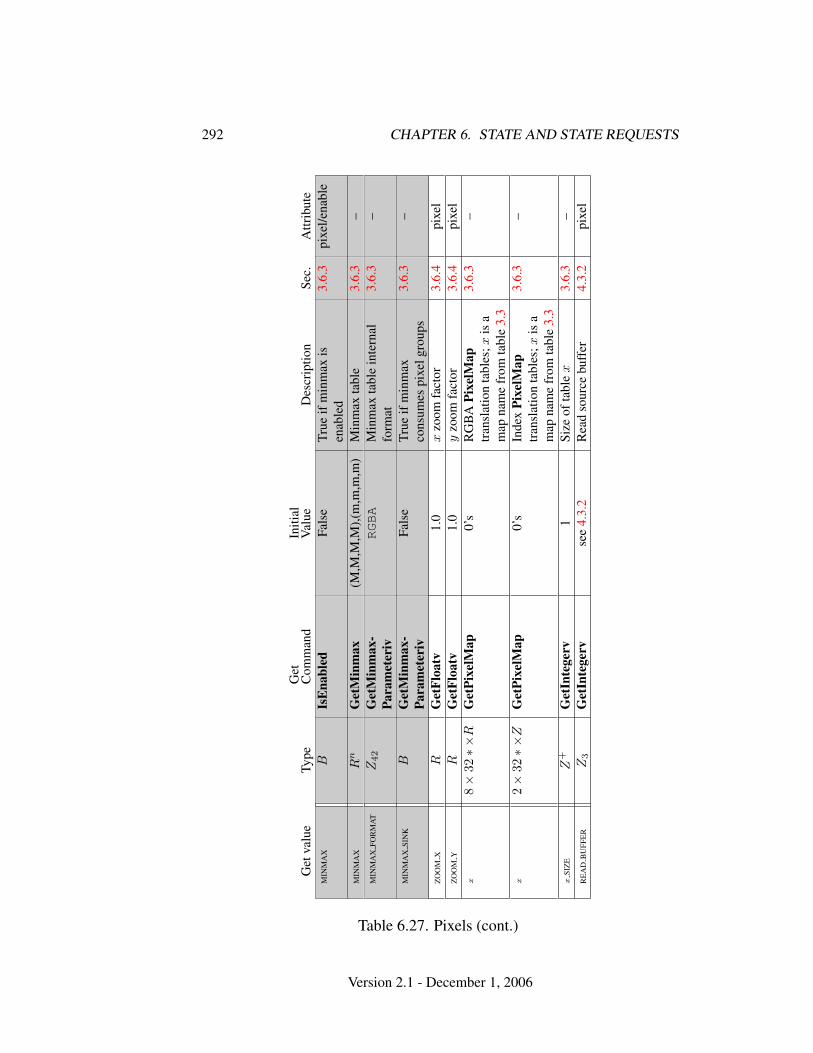
292 CHAPTER 6. STATE AND STATE REQUESTS
Get
valu
eTy
peG
etC
omm
and
Initi
alV
alue
Des
crip
tion
Sec.
Attr
ibut
eM
INM
AX
BIs
Ena
bled
Fals
eTr
ueif
min
max
isen
able
d3.
6.3
pixe
l/ena
ble
MIN
MA
XR
nG
etM
inm
ax(M
,M,M
,M),(
m,m
,m,m
)M
inm
axta
ble
3.6.
3–
MIN
MA
XFO
RM
AT
Z42
Get
Min
max
-Pa
ram
eter
ivRGBA
Min
max
tabl
ein
tern
alfo
rmat
3.6.
3–
MIN
MA
XSI
NK
BG
etM
inm
ax-
Para
met
eriv
Fals
eTr
ueif
min
max
cons
umes
pixe
lgro
ups
3.6.
3–
ZO
OM
XR
Get
Floa
tv1.
0x
zoom
fact
or3.
6.4
pixe
lZ
OO
MY
RG
etFl
oatv
1.0
yzo
omfa
ctor
3.6.
4pi
xel
x8×
32∗×
RG
etPi
xelM
ap0’
sR
GB
APi
xelM
aptr
ansl
atio
nta
bles
;xis
am
apna
me
from
tabl
e3.
3
3.6.
3–
x2×
32∗×
ZG
etPi
xelM
ap0’
sIn
dex
Pixe
lMap
tran
slat
ion
tabl
es;x
isa
map
nam
efr
omta
ble
3.3
3.6.
3–
xSI
ZE
Z+
Get
Inte
gerv
1Si
zeof
tabl
ex
3.6.
3–
RE
AD
BU
FFE
RZ
3G
etIn
tege
rvse
e4.
3.2
Rea
dso
urce
buff
er4.
3.2
pixe
l
Table 6.27. Pixels (cont.)
Version 2.1 - December 1, 2006
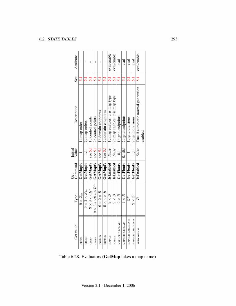
6.2. STATE TABLES 293
Get
valu
eTy
peG
etC
omm
and
Initi
alV
alue
Des
crip
tion
Sec.
Attr
ibut
eO
RD
ER
9×
Z8∗
Get
Map
iv1
1dm
apor
der
5.1
–O
RD
ER
9×
2×
Z8∗
Get
Map
iv1,
12d
map
orde
rs5.
1–
CO
EFF
9×
8∗×
Rn
Get
Map
fvse
e5.
11d
cont
rolp
oint
s5.
1–
CO
EFF
9×
8∗×
8∗×
Rn
Get
Map
fvse
e5.
12d
cont
rolp
oint
s5.
1–
DO
MA
IN9×
2×
RG
etM
apfv
see
5.1
1ddo
mai
nen
dpoi
nts
5.1
–D
OM
AIN
9×
4×
RG
etM
apfv
see
5.1
2ddo
mai
nen
dpoi
nts
5.1
–M
AP1
x9×
BIs
Ena
bled
Fals
e1d
map
enab
les:
xis
map
type
5.1
eval
/ena
ble
MA
P2x
9×
BIs
Ena
bled
Fals
e2d
map
enab
les:
xis
map
type
5.1
eval
/ena
ble
MA
P1G
RID
DO
MA
IN2×
RG
etFl
oatv
0,1
1dgr
iden
dpoi
nts
5.1
eval
MA
P2G
RID
DO
MA
IN4×
RG
etFl
oatv
0,1;
0,1
2dgr
iden
dpoi
nts
5.1
eval
MA
P1G
RID
SEG
ME
NT
SZ
+G
etFl
oatv
11d
grid
divi
sion
s5.
1ev
alM
AP2
GR
IDSE
GM
EN
TS
2×
Z+
Get
Floa
tv1,
12d
grid
divi
sion
s5.
1ev
alA
UTO
NO
RM
AL
BIs
Ena
bled
Fals
eTr
ueif
auto
mat
icno
rmal
gene
ratio
nen
able
d5.
1ev
al/e
nabl
e
Table 6.28. Evaluators (GetMap takes a map name)
Version 2.1 - December 1, 2006
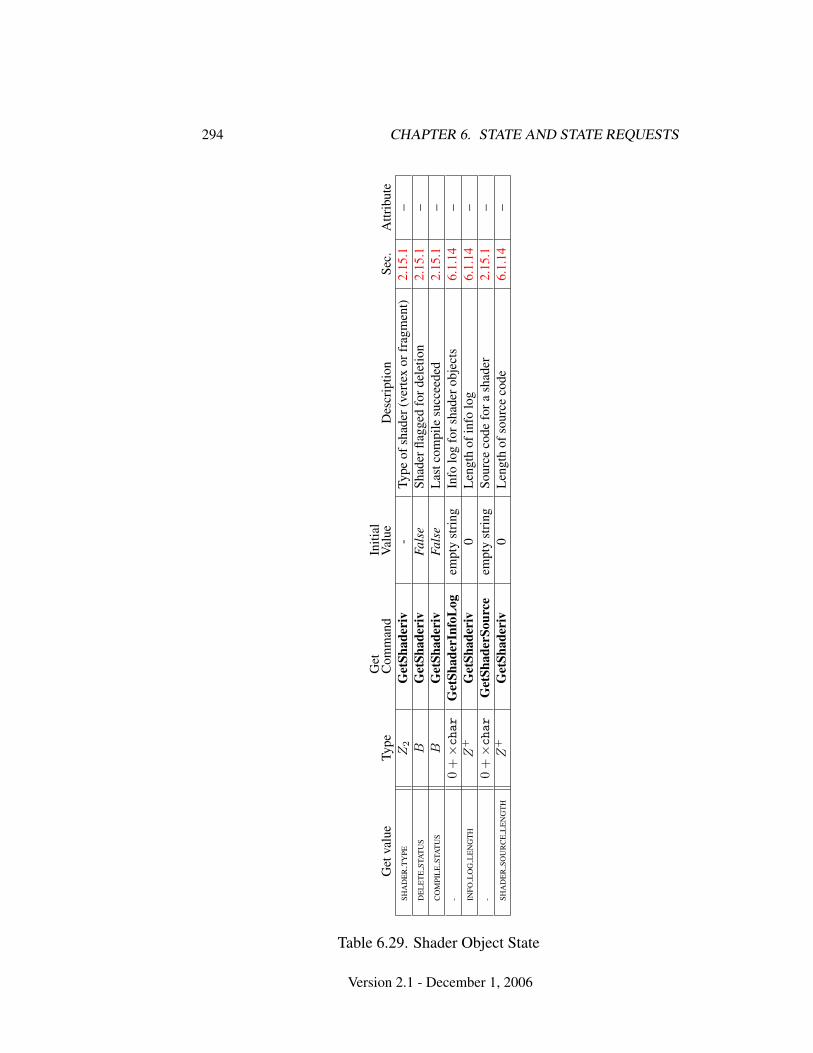
294 CHAPTER 6. STATE AND STATE REQUESTS
Get
valu
eTy
peG
etC
omm
and
Initi
alV
alue
Des
crip
tion
Sec.
Attr
ibut
eSH
AD
ER
TY
PEZ
2G
etSh
ader
iv-
Type
ofsh
ader
(ver
tex
orfr
agm
ent)
2.15
.1–
DE
LE
TE
STA
TU
SB
Get
Shad
eriv
Fals
eSh
ader
flagg
edfo
rdel
etio
n2.
15.1
–C
OM
PIL
EST
AT
US
BG
etSh
ader
ivFa
lse
Las
tcom
pile
succ
eede
d2.
15.1
–-
0+×char
Get
Shad
erIn
foL
ogem
pty
stri
ngIn
folo
gfo
rsha
dero
bjec
ts6.
1.14
–IN
FOL
OG
LE
NG
TH
Z+
Get
Shad
eriv
0L
engt
hof
info
log
6.1.
14–
-0
+×char
Get
Shad
erSo
urce
empt
yst
ring
Sour
ceco
defo
rash
ader
2.15
.1–
SHA
DE
RSO
UR
CE
LE
NG
TH
Z+
Get
Shad
eriv
0L
engt
hof
sour
ceco
de6.
1.14
–
Table 6.29. Shader Object State
Version 2.1 - December 1, 2006
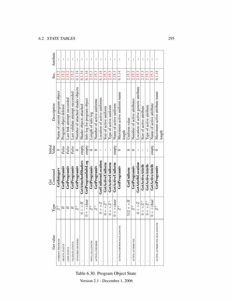
6.2. STATE TABLES 295
Get
valu
eTy
peG
etC
omm
and
Initi
alV
alue
Des
crip
tion
Sec.
Attr
ibut
eC
UR
RE
NT
PRO
GR
AM
Z+
Get
Inte
gerv
0N
ame
ofcu
rren
tpro
gram
obje
ct2.
15.2
–D
EL
ET
EST
AT
US
BG
etPr
ogra
miv
Fals
ePr
ogra
mob
ject
dele
ted
2.15
.2–
LIN
KST
AT
US
BG
etPr
ogra
miv
Fals
eL
astl
ink
atte
mpt
succ
eede
d2.
15.2
–VA
LID
AT
EST
AT
US
BG
etPr
ogra
miv
Fals
eL
astv
alid
ate
atte
mpt
succ
eede
d2.
15.2
–A
TTA
CH
ED
SHA
DE
RS
Z+
Get
Prog
ram
iv0
Num
bero
fatta
ched
shad
erob
ject
s6.
1.14
–-
0+×
HG
etA
ttac
hedS
hade
rsem
pty
Shad
erob
ject
sat
tach
ed6.
1.14
–-
0+×char
Get
Prog
ram
Info
Log
empt
yIn
folo
gfo
rpro
gram
obje
ct6.
1.14
–IN
FOL
OG
LE
NG
TH
Z+
Get
Prog
ram
iv0
Len
gth
ofin
folo
g2.
15.3
–A
CT
IVE
UN
IFO
RM
SZ
+G
etPr
ogra
miv
0N
umbe
rofa
ctiv
eun
ifor
ms
2.15
.3–
-0
+×
ZG
etU
nifo
rmL
ocat
ion
–L
ocat
ion
ofac
tive
unif
orm
s6.
1.14
–-
0+×
Z+
Get
Act
iveU
nifo
rm–
Size
ofac
tive
unif
orm
2.15
.3–
-0
+×
Z+
Get
Act
iveU
nifo
rm–
Type
ofac
tive
unif
orm
2.15
.3–
-0
+×char
Get
Act
iveU
nifo
rmem
pty
Nam
eof
activ
eun
ifor
m2.
15.3
–A
CT
IVE
UN
IFO
RM
MA
XL
EN
GT
HZ
+G
etPr
ogra
miv
0M
axim
umac
tive
unif
orm
nam
ele
ngth
6.1.
14–
512
+×
RG
etU
nifo
rm0
Uni
form
valu
e2.
15.3
–A
CT
IVE
AT
TR
IBU
TE
SZ
+G
etPr
ogra
miv
0N
umbe
rofa
ctiv
eat
trib
utes
2.15
.3–
-0
+×
ZG
etA
ttri
bLoc
atio
n–
Loc
atio
nof
activ
ege
neri
cat
trib
ute
2.15
.3–
-0
+×
Z+
Get
Act
iveA
ttri
b–
Size
ofac
tive
attr
ibut
e2.
15.3
–-
0+×
Z+
Get
Act
iveA
ttri
b–
Type
ofac
tive
attr
ibut
e2.
15.3
–-
0+×char
Get
Act
iveA
ttri
bem
pty
Nam
eof
activ
eat
trib
ute
2.15
.3–
AC
TIV
EA
TT
RIB
UT
ES
MA
XL
EN
GT
HZ
+G
etPr
ogra
miv
0M
axim
umac
tive
attr
ibut
ena
me
leng
th6.
1.14
–
Table 6.30. Program Object State
Version 2.1 - December 1, 2006
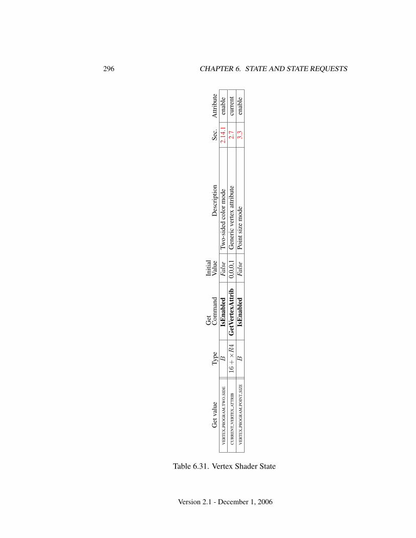
296 CHAPTER 6. STATE AND STATE REQUESTS
Get
valu
eTy
peG
etC
omm
and
Initi
alV
alue
Des
crip
tion
Sec.
Attr
ibut
eV
ER
TE
XPR
OG
RA
MT
WO
SID
EB
IsE
nabl
edFa
lse
Two-
side
dco
lorm
ode
2.14
.1en
able
CU
RR
EN
TV
ER
TE
XA
TT
RIB
16+×
R4
Get
Vert
exA
ttri
b0,
0,0,
1G
ener
icve
rtex
attr
ibut
e2.
7cu
rren
tV
ER
TE
XPR
OG
RA
MPO
INT
SIZ
EB
IsE
nabl
edFa
lse
Poin
tsiz
em
ode
3.3
enab
le
Table 6.31. Vertex Shader State
Version 2.1 - December 1, 2006
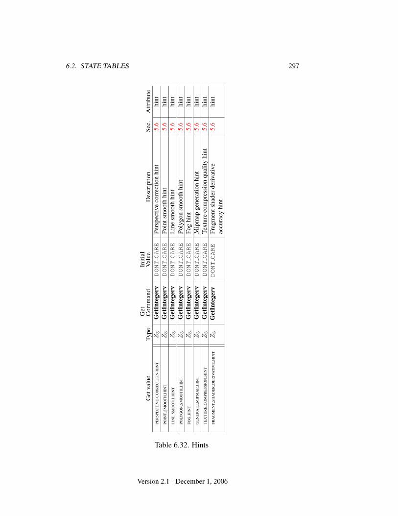
6.2. STATE TABLES 297
Get
valu
eTy
peG
etC
omm
and
Initi
alV
alue
Des
crip
tion
Sec.
Attr
ibut
ePE
RSP
EC
TIV
EC
OR
RE
CT
ION
HIN
TZ
3G
etIn
tege
rvDONTCARE
Pers
pect
ive
corr
ectio
nhi
nt5.
6hi
ntPO
INT
SMO
OT
HH
INT
Z3
Get
Inte
gerv
DONTCARE
Poin
tsm
ooth
hint
5.6
hint
LIN
ESM
OO
TH
HIN
TZ
3G
etIn
tege
rvDONTCARE
Lin
esm
ooth
hint
5.6
hint
POLY
GO
NSM
OO
TH
HIN
TZ
3G
etIn
tege
rvDONTCARE
Poly
gon
smoo
thhi
nt5.
6hi
ntFO
GH
INT
Z3
Get
Inte
gerv
DONTCARE
Fog
hint
5.6
hint
GE
NE
RA
TE
MIP
MA
PH
INT
Z3
Get
Inte
gerv
DONTCARE
Mip
map
gene
ratio
nhi
nt5.
6hi
ntT
EX
TU
RE
CO
MPR
ESS
ION
HIN
TZ
3G
etIn
tege
rvDONTCARE
Text
ure
com
pres
sion
qual
ityhi
nt5.
6hi
ntFR
AG
ME
NT
SHA
DE
RD
ER
IVA
TIV
EH
INT
Z3
Get
Inte
gerv
DONTCARE
Frag
men
tsha
derd
eriv
ativ
eac
cura
cyhi
nt5.
6hi
nt
Table 6.32. Hints
Version 2.1 - December 1, 2006
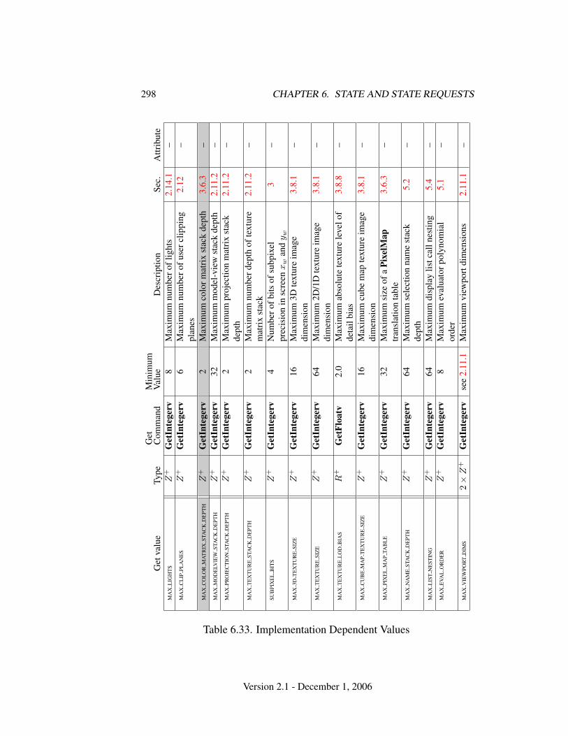
298 CHAPTER 6. STATE AND STATE REQUESTS
Get
valu
eTy
peG
etC
omm
and
Min
imum
Val
ueD
escr
iptio
nSe
c.A
ttrib
ute
MA
XL
IGH
TS
Z+
Get
Inte
gerv
8M
axim
umnu
mbe
rofl
ight
s2.
14.1
–M
AX
CL
IPPL
AN
ES
Z+
Get
Inte
gerv
6M
axim
umnu
mbe
rofu
serc
lippi
ngpl
anes
2.12
–
MA
XC
OL
OR
MA
TR
IXST
AC
KD
EPT
HZ
+G
etIn
tege
rv2
Max
imum
colo
rmat
rix
stac
kde
pth
3.6.
3–
MA
XM
OD
ELV
IEW
STA
CK
DE
PTH
Z+
Get
Inte
gerv
32M
axim
umm
odel
-vie
wst
ack
dept
h2.
11.2
–M
AX
PRO
JEC
TIO
NST
AC
KD
EPT
HZ
+G
etIn
tege
rv2
Max
imum
proj
ectio
nm
atri
xst
ack
dept
h2.
11.2
–
MA
XT
EX
TU
RE
STA
CK
DE
PTH
Z+
Get
Inte
gerv
2M
axim
umnu
mbe
rdep
thof
text
ure
mat
rix
stac
k2.
11.2
–
SUB
PIX
EL
BIT
SZ
+G
etIn
tege
rv4
Num
bero
fbits
ofsu
bpix
elpr
ecis
ion
insc
reen
xw
and
y w
3–
MA
X3D
TE
XT
UR
ESI
ZE
Z+
Get
Inte
gerv
16M
axim
um3D
text
ure
imag
edi
men
sion
3.8.
1–
MA
XT
EX
TU
RE
SIZ
EZ
+G
etIn
tege
rv64
Max
imum
2D/1
Dte
xtur
eim
age
dim
ensi
on3.
8.1
–
MA
XT
EX
TU
RE
LO
DB
IAS
R+
Get
Floa
tv2.
0M
axim
umab
solu
tete
xtur
ele
velo
fde
tail
bias
3.8.
8–
MA
XC
UB
EM
AP
TE
XT
UR
ESI
ZE
Z+
Get
Inte
gerv
16M
axim
umcu
bem
apte
xtur
eim
age
dim
ensi
on3.
8.1
–
MA
XPI
XE
LM
AP
TAB
LE
Z+
Get
Inte
gerv
32M
axim
umsi
zeof
aPi
xelM
aptr
ansl
atio
nta
ble
3.6.
3–
MA
XN
AM
EST
AC
KD
EPT
HZ
+G
etIn
tege
rv64
Max
imum
sele
ctio
nna
me
stac
kde
pth
5.2
–
MA
XL
IST
NE
STIN
GZ
+G
etIn
tege
rv64
Max
imum
disp
lay
listc
alln
estin
g5.
4–
MA
XE
VAL
OR
DE
RZ
+G
etIn
tege
rv8
Max
imum
eval
uato
rpol
ynom
ial
orde
r5.
1–
MA
XV
IEW
POR
TD
IMS
2×
Z+
Get
Inte
gerv
see
2.11
.1M
axim
umvi
ewpo
rtdi
men
sion
s2.
11.1
–
Table 6.33. Implementation Dependent Values
Version 2.1 - December 1, 2006
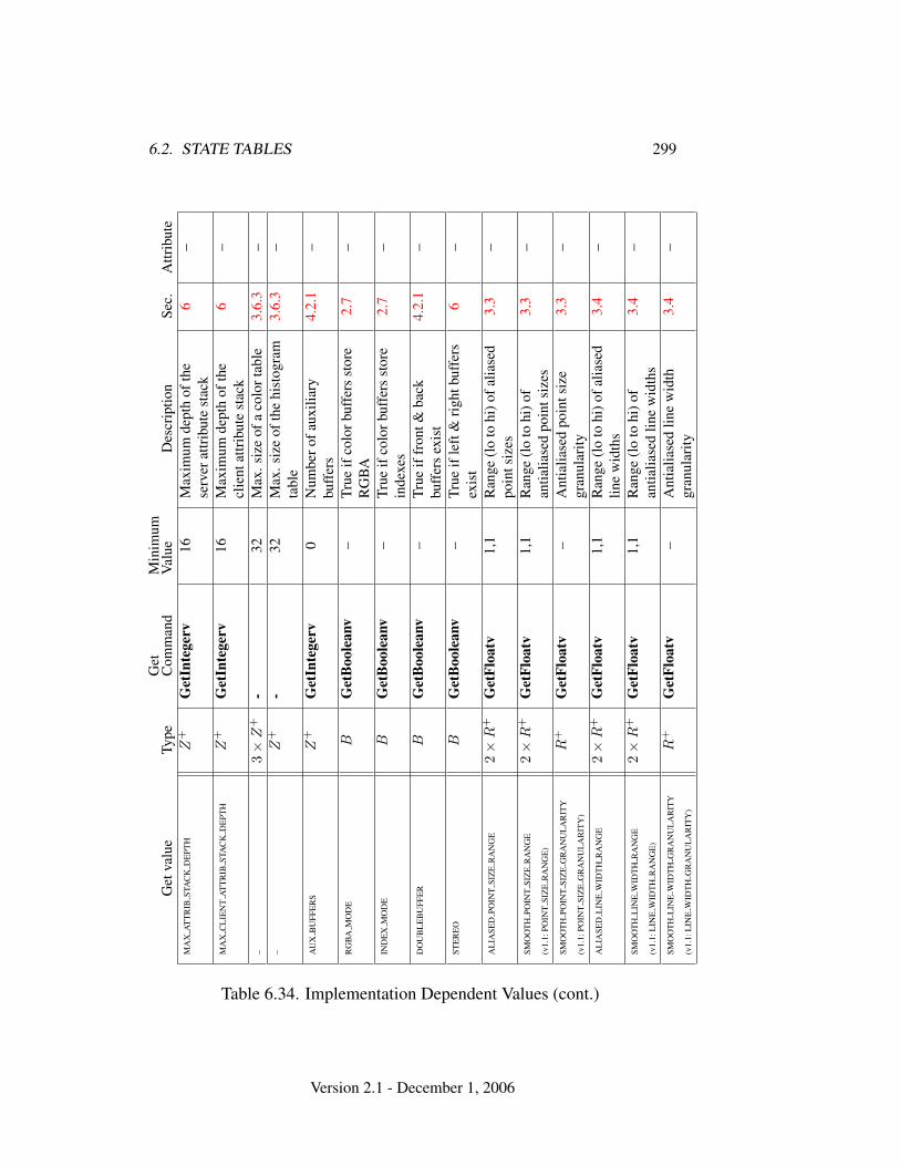
6.2. STATE TABLES 299G
etva
lue
Type
Get
Com
man
dM
inim
umV
alue
Des
crip
tion
Sec.
Attr
ibut
eM
AX
AT
TR
IBST
AC
KD
EPT
HZ
+G
etIn
tege
rv16
Max
imum
dept
hof
the
serv
erat
trib
ute
stac
k6
–
MA
XC
LIE
NT
AT
TR
IBST
AC
KD
EPT
HZ
+G
etIn
tege
rv16
Max
imum
dept
hof
the
clie
ntat
trib
ute
stac
k6
–
–3×
Z+
-32
Max
.siz
eof
aco
lort
able
3.6.
3–
–Z
+-
32M
ax.s
ize
ofth
ehi
stog
ram
tabl
e3.
6.3
–
AU
XB
UFF
ER
SZ
+G
etIn
tege
rv0
Num
bero
faux
iliar
ybu
ffer
s4.
2.1
–
RG
BA
MO
DE
BG
etB
oole
anv
–Tr
ueif
colo
rbuf
fers
stor
eR
GB
A2.
7–
IND
EX
MO
DE
BG
etB
oole
anv
–Tr
ueif
colo
rbuf
fers
stor
ein
dexe
s2.
7–
DO
UB
LE
BU
FFE
RB
Get
Boo
lean
v–
True
iffr
ont&
back
buff
ers
exis
t4.
2.1
–
STE
RE
OB
Get
Boo
lean
v–
True
ifle
ft&
righ
tbuf
fers
exis
t6
–
AL
IASE
DPO
INT
SIZ
ER
AN
GE
2×
R+
Get
Floa
tv1,
1R
ange
(lo
tohi
)ofa
liase
dpo
ints
izes
3.3
–
SMO
OT
HPO
INT
SIZ
ER
AN
GE
(v1.
1:PO
INT
SIZ
ER
AN
GE
)
2×
R+
Get
Floa
tv1,
1R
ange
(lo
tohi
)of
antia
liase
dpo
ints
izes
3.3
–
SMO
OT
HPO
INT
SIZ
EG
RA
NU
LA
RIT
Y
(v1.
1:PO
INT
SIZ
EG
RA
NU
LA
RIT
Y)
R+
Get
Floa
tv–
Ant
ialia
sed
poin
tsiz
egr
anul
arity
3.3
–
AL
IASE
DL
INE
WID
TH
RA
NG
E2×
R+
Get
Floa
tv1,
1R
ange
(lo
tohi
)ofa
liase
dlin
ew
idth
s3.
4–
SMO
OT
HL
INE
WID
TH
RA
NG
E
(v1.
1:L
INE
WID
TH
RA
NG
E)
2×
R+
Get
Floa
tv1,
1R
ange
(lo
tohi
)of
antia
liase
dlin
ew
idth
s3.
4–
SMO
OT
HL
INE
WID
TH
GR
AN
UL
AR
ITY
(v1.
1:L
INE
WID
TH
GR
AN
UL
AR
ITY
)
R+
Get
Floa
tv–
Ant
ialia
sed
line
wid
thgr
anul
arity
3.4
–
Table 6.34. Implementation Dependent Values (cont.)
Version 2.1 - December 1, 2006
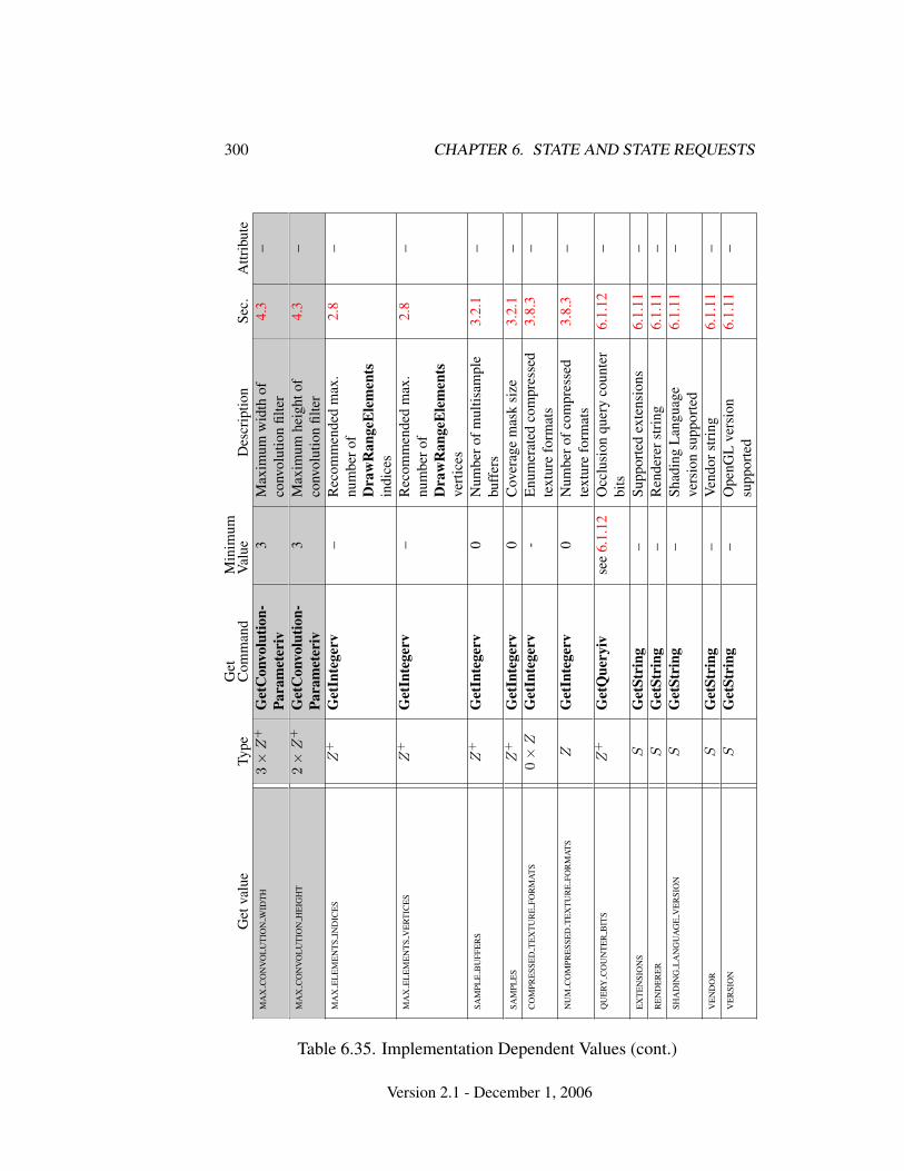
300 CHAPTER 6. STATE AND STATE REQUESTS
Get
valu
eTy
peG
etC
omm
and
Min
imum
Val
ueD
escr
iptio
nSe
c.A
ttrib
ute
MA
XC
ON
VO
LU
TIO
NW
IDT
H3×
Z+
Get
Con
volu
tion-
Para
met
eriv
3M
axim
umw
idth
ofco
nvol
utio
nfil
ter
4.3
–
MA
XC
ON
VO
LU
TIO
NH
EIG
HT
2×
Z+
Get
Con
volu
tion-
Para
met
eriv
3M
axim
umhe
ight
ofco
nvol
utio
nfil
ter
4.3
–
MA
XE
LE
ME
NT
SIN
DIC
ES
Z+
Get
Inte
gerv
–R
ecom
men
ded
max
.nu
mbe
rof
Dra
wR
ange
Ele
men
tsin
dice
s
2.8
–
MA
XE
LE
ME
NT
SV
ER
TIC
ES
Z+
Get
Inte
gerv
–R
ecom
men
ded
max
.nu
mbe
rof
Dra
wR
ange
Ele
men
tsve
rtic
es
2.8
–
SAM
PLE
BU
FFE
RS
Z+
Get
Inte
gerv
0N
umbe
rofm
ultis
ampl
ebu
ffer
s3.
2.1
–
SAM
PLE
SZ
+G
etIn
tege
rv0
Cov
erag
em
ask
size
3.2.
1–
CO
MPR
ESS
ED
TE
XT
UR
EFO
RM
AT
S0×
ZG
etIn
tege
rv-
Enu
mer
ated
com
pres
sed
text
ure
form
ats
3.8.
3–
NU
MC
OM
PRE
SSE
DT
EX
TU
RE
FOR
MA
TS
ZG
etIn
tege
rv0
Num
bero
fcom
pres
sed
text
ure
form
ats
3.8.
3–
QU
ERY
CO
UN
TE
RB
ITS
Z+
Get
Que
ryiv
see
6.1.
12O
cclu
sion
quer
yco
unte
rbi
ts6.
1.12
–
EX
TE
NSI
ON
SS
Get
Stri
ng–
Supp
orte
dex
tens
ions
6.1.
11–
RE
ND
ER
ER
SG
etSt
ring
–R
ende
rers
trin
g6.
1.11
–SH
AD
ING
LA
NG
UA
GE
VE
RSI
ON
SG
etSt
ring
–Sh
adin
gL
angu
age
vers
ion
supp
orte
d6.
1.11
–
VE
ND
OR
SG
etSt
ring
–V
endo
rstr
ing
6.1.
11–
VE
RSI
ON
SG
etSt
ring
–O
penG
Lve
rsio
nsu
ppor
ted
6.1.
11–
Table 6.35. Implementation Dependent Values (cont.)
Version 2.1 - December 1, 2006
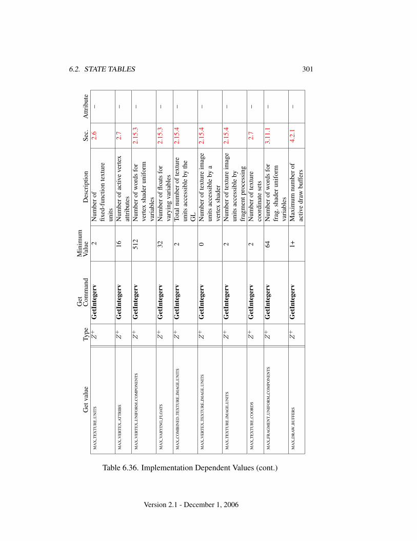
6.2. STATE TABLES 301
Get
valu
eTy
peG
etC
omm
and
Min
imum
Val
ueD
escr
iptio
nSe
c.A
ttrib
ute
MA
XT
EX
TU
RE
UN
ITS
Z+
Get
Inte
gerv
2N
umbe
rof
fixed
-fun
ctio
nte
xtur
eun
its
2.6
–
MA
XV
ER
TE
XA
TT
RIB
SZ
+G
etIn
tege
rv16
Num
bero
fact
ive
vert
exat
trib
utes
2.7
–
MA
XV
ER
TE
XU
NIF
OR
MC
OM
PON
EN
TS
Z+
Get
Inte
gerv
512
Num
bero
fwor
dsfo
rve
rtex
shad
erun
ifor
mva
riab
les
2.15
.3–
MA
XVA
RYIN
GFL
OA
TS
Z+
Get
Inte
gerv
32N
umbe
roffl
oats
for
vary
ing
vari
able
s2.
15.3
–
MA
XC
OM
BIN
ED
TE
XT
UR
EIM
AG
EU
NIT
SZ
+G
etIn
tege
rv2
Tota
lnum
bero
ftex
ture
units
acce
ssib
leby
the
GL
2.15
.4–
MA
XV
ER
TE
XT
EX
TU
RE
IMA
GE
UN
ITS
Z+
Get
Inte
gerv
0N
umbe
roft
extu
reim
age
units
acce
ssib
leby
ave
rtex
shad
er
2.15
.4–
MA
XT
EX
TU
RE
IMA
GE
UN
ITS
Z+
Get
Inte
gerv
2N
umbe
roft
extu
reim
age
units
acce
ssib
leby
frag
men
tpro
cess
ing
2.15
.4–
MA
XT
EX
TU
RE
CO
OR
DS
Z+
Get
Inte
gerv
2N
umbe
roft
extu
reco
ordi
nate
sets
2.7
–
MA
XFR
AG
ME
NT
UN
IFO
RM
CO
MPO
NE
NT
SZ
+G
etIn
tege
rv64
Num
bero
fwor
dsfo
rfr
ag.s
hade
runi
form
vari
able
s
3.11
.1–
MA
XD
RA
WB
UFF
ER
SZ
+G
etIn
tege
rv1+
Max
imum
num
bero
fac
tive
draw
buff
ers
4.2.
1–
Table 6.36. Implementation Dependent Values (cont.)
Version 2.1 - December 1, 2006
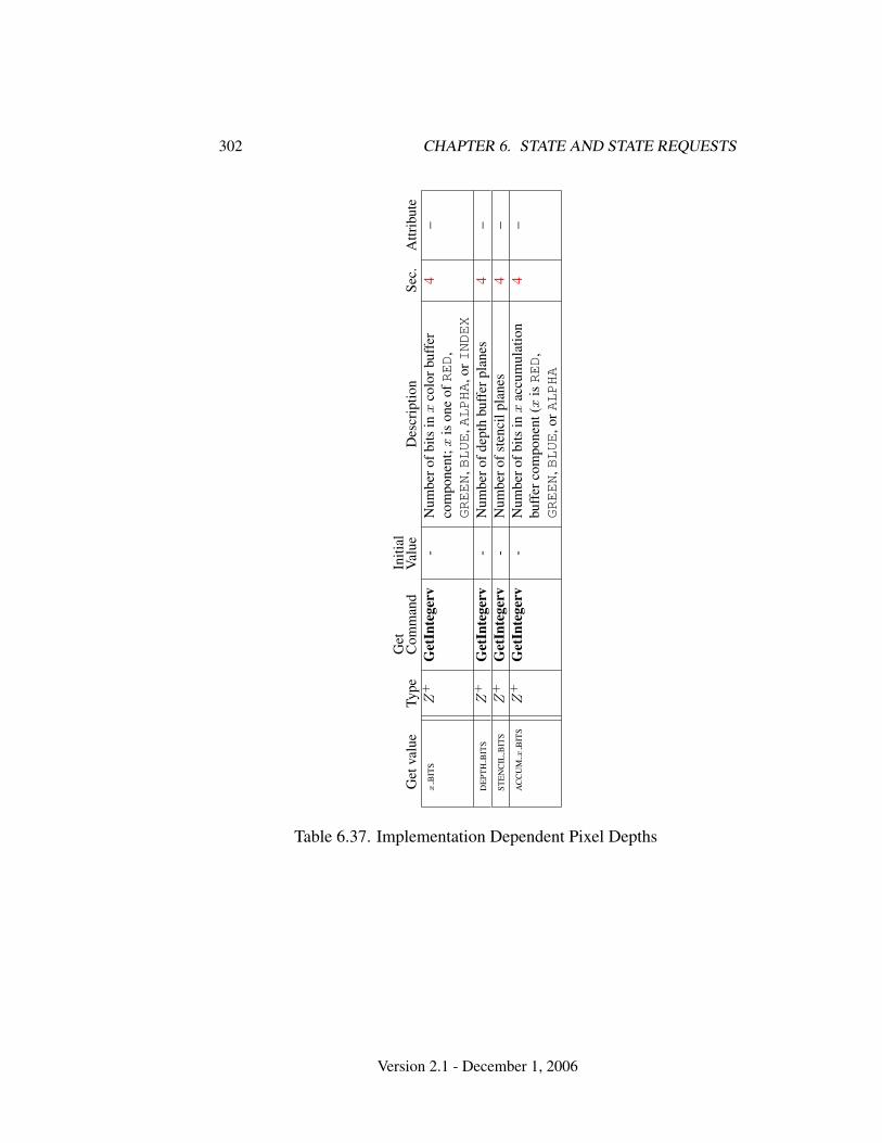
302 CHAPTER 6. STATE AND STATE REQUESTS
Get
valu
eTy
peG
etC
omm
and
Initi
alV
alue
Des
crip
tion
Sec.
Attr
ibut
ex
BIT
SZ
+G
etIn
tege
rv-
Num
bero
fbits
inx
colo
rbuf
fer
com
pone
nt;x
ison
eofRED
,GREEN
,BLUE
,ALPHA
,orINDEX
4–
DE
PTH
BIT
SZ
+G
etIn
tege
rv-
Num
bero
fdep
thbu
ffer
plan
es4
–ST
EN
CIL
BIT
SZ
+G
etIn
tege
rv-
Num
bero
fste
ncil
plan
es4
–A
CC
UM
xB
ITS
Z+
Get
Inte
gerv
-N
umbe
rofb
itsin
xac
cum
ulat
ion
buff
erco
mpo
nent
(xisRED
,GREEN
,BLUE
,orALPHA
4–
Table 6.37. Implementation Dependent Pixel Depths
Version 2.1 - December 1, 2006
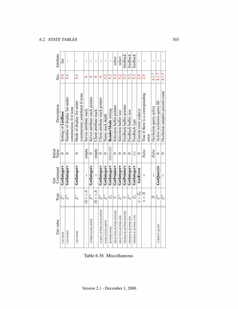
6.2. STATE TABLES 303
Get
valu
eTy
peG
etC
omm
and
Initi
alV
alue
Des
crip
tion
Sec.
Attr
ibut
eL
IST
BA
SEZ
+G
etIn
tege
rv0
Setti
ngof
Lis
tBas
e5.
4lis
tL
IST
IND
EX
Z+
Get
Inte
gerv
0N
umbe
rofd
ispl
aylis
tund
erco
nstr
uctio
n;0
ifno
ne5.
4–
LIS
TM
OD
EZ
+G
etIn
tege
rv0
Mod
eof
disp
lay
listu
nder
cons
truc
tion;
unde
fined
ifno
ne5.
4–
–16∗×
A–
empt
ySe
rver
attr
ibut
est
ack
6–
AT
TR
IBST
AC
KD
EPT
HZ
+G
etIn
tege
rv0
Serv
erat
trib
ute
stac
kpo
inte
r6
––
16∗×
A–
empt
yC
lient
attr
ibut
est
ack
6–
CL
IEN
TA
TT
RIB
STA
CK
DE
PTH
Z+
Get
Inte
gerv
0C
lient
attr
ibut
est
ack
poin
ter
6–
NA
ME
STA
CK
DE
PTH
Z+
Get
Inte
gerv
0N
ame
stac
kde
pth
5.2
–R
EN
DE
RM
OD
EZ
3G
etIn
tege
rvRENDER
Ren
derM
ode
setti
ng5.
2–
SEL
EC
TIO
NB
UFF
ER
POIN
TE
RY
Get
Poin
terv
0Se
lect
ion
buff
erpo
inte
r5.
2se
lect
SEL
EC
TIO
NB
UFF
ER
SIZ
EZ
+G
etIn
tege
rv0
Sele
ctio
nbu
ffer
size
5.2
sele
ctFE
ED
BA
CK
BU
FFE
RPO
INT
ER
YG
etPo
inte
rv0
Feed
back
buff
erpo
inte
r5.
3fe
edba
ckFE
ED
BA
CK
BU
FFE
RSI
ZE
Z+
Get
Inte
gerv
0Fe
edba
ckbu
ffer
size
5.3
feed
back
FEE
DB
AC
KB
UFF
ER
TY
PEZ
5G
etIn
tege
rv2D
Feed
back
type
5.3
feed
back
–n×
Z8
Get
Err
or0
Cur
rent
erro
rcod
e(s)
2.5
––
n×
B–
Fals
eTr
ueif
ther
eis
aco
rres
pond
ing
erro
r2.
5–
B–
Fals
eO
cclu
sion
quer
yac
tive
4.1.
7–
CU
RR
EN
TQ
UE
RYZ
+G
etQ
uery
iv0
Act
ive
occl
usio
nqu
ery
ID4.
1.7
–Z
+–
0O
cclu
sion
sam
ples
-pas
sed
coun
t4.
1.7
–
Table 6.38. Miscellaneous
Version 2.1 - December 1, 2006

Appendix A
Invariance
The OpenGL specification is not pixel exact. It therefore does not guarantee an ex-act match between images produced by different GL implementations. However,the specification does specify exact matches, in some cases, for images producedby the same implementation. The purpose of this appendix is to identify and pro-vide justification for those cases that require exact matches.
A.1 Repeatability
The obvious and most fundamental case is repeated issuance of a series of GL com-mands. For any given GL and framebuffer state vector, and for any GL command,the resulting GL and framebuffer state must be identical whenever the command isexecuted on that initial GL and framebuffer state.
One purpose of repeatability is avoidance of visual artifacts when a double-buffered scene is redrawn. If rendering is not repeatable, swapping between twobuffers rendered with the same command sequence may result in visible changesin the image. Such false motion is distracting to the viewer. Another reason forrepeatability is testability.
Repeatability, while important, is a weak requirement. Given only repeata-bility as a requirement, two scenes rendered with one (small) polygon changedin position might differ at every pixel. Such a difference, while within the lawof repeatability, is certainly not within its spirit. Additional invariance rules aredesirable to ensure useful operation.
304

A.2. MULTI-PASS ALGORITHMS 305
A.2 Multi-pass Algorithms
Invariance is necessary for a whole set of useful multi-pass algorithms. Such al-gorithms render multiple times, each time with a different GL mode vector, toeventually produce a result in the framebuffer. Examples of these algorithms in-clude:
• “Erasing” a primitive from the framebuffer by redrawing it, either in a dif-ferent color or using the XOR logical operation.
• Using stencil operations to compute capping planes.
On the other hand, invariance rules can greatly increase the complexity of high-performance implementations of the GL. Even the weak repeatability requirementsignificantly constrains a parallel implementation of the GL. Because GL imple-mentations are required to implement ALL GL capabilities, not just a convenientsubset, those that utilize hardware acceleration are expected to alternate betweenhardware and software modules based on the current GL mode vector. A stronginvariance requirement forces the behavior of the hardware and software modulesto be identical, something that may be very difficult to achieve (for example, if thehardware does floating-point operations with different precision than the software).
What is desired is a compromise that results in many compliant, high-performance implementations, and in many software vendors choosing to port toOpenGL.
A.3 Invariance Rules
For a given instantiation of an OpenGL rendering context:
Rule 1 For any given GL and framebuffer state vector, and for any given GL com-mand, the resulting GL and framebuffer state must be identical each time the com-mand is executed on that initial GL and framebuffer state.
Rule 2 Changes to the following state values have no side effects (the use of anyother state value is not affected by the change):
Required:
• Framebuffer contents (all bitplanes)
• The color buffers enabled for writing
• The values of matrices other than the top-of-stack matrices
Version 2.1 - December 1, 2006
306 APPENDIX A. INVARIANCE
• Scissor parameters (other than enable)
• Writemasks (color, index, depth, stencil)
• Clear values (color, index, depth, stencil, accumulation)
◦ Current values (color, index, normal, texture coords, edgeflag)
◦ Current raster color, index and texture coordinates.
◦ Material properties (ambient, diffuse, specular, emission, shininess)
Strongly suggested:
• Matrix mode
• Matrix stack depths
• Alpha test parameters (other than enable)
• Stencil parameters (other than enable)
• Depth test parameters (other than enable)
• Blend parameters (other than enable)
• Logical operation parameters (other than enable)
• Pixel storage and transfer state
• Evaluator state (except as it affects the vertex data generated by theevaluators)
• Polygon offset parameters (other than enables, and except as they affectthe depth values of fragments)
Corollary 1 Fragment generation is invariant with respect to the state valuesmarked with • in Rule 2.
Corollary 2 The window coordinates (x, y, and z) of generated fragments are alsoinvariant with respect to
Required:
• Current values (color, color index, normal, texture coords, edgeflag)
• Current raster color, color index, and texture coordinates
• Material properties (ambient, diffuse, specular, emission, shininess)
Rule 3 The arithmetic of each per-fragment operation is invariant except with re-spect to parameters that directly control it (the parameters that control the alphatest, for instance, are the alpha test enable, the alpha test function, and the alphatest reference value).
Version 2.1 - December 1, 2006

A.4. WHAT ALL THIS MEANS 307
Corollary 3 Images rendered into different color buffers sharing the same frame-buffer, either simultaneously or separately using the same command sequence, arepixel identical.
Rule 4 The same vertex or fragment shader will produce the same result whenrun multiple times with the same input. The wording ’the same shader’ means aprogram object that is populated with the same source strings, which are compiledand then linked, possibly multiple times, and which program object is then executedusing the same GL state vector.
Rule 5 All fragment shaders that either conditionally or unconditionally assigngl FragCoord.z to gl FragDepth are depth-invariant with respect to eachother, for those fragments where the assignment to gl FragDepth actually isdone.
A.4 What All This Means
Hardware accelerated GL implementations are expected to default to software op-eration when some GL state vectors are encountered. Even the weak repeatabilityrequirement means, for example, that OpenGL implementations cannot apply hys-teresis to this swap, but must instead guarantee that a given mode vector impliesthat a subsequent command always is executed in either the hardware or the soft-ware machine.
The stronger invariance rules constrain when the switch from hardware to soft-ware rendering can occur, given that the software and hardware renderers are notpixel identical. For example, the switch can be made when blending is enabled ordisabled, but it should not be made when a change is made to the blending param-eters.
Because floating point values may be represented using different formats in dif-ferent renderers (hardware and software), many OpenGL state values may changesubtly when renderers are swapped. This is the type of state value change that Rule1 seeks to avoid.
Version 2.1 - December 1, 2006
Appendix B
Corollaries
The following observations are derived from the body and the other appendixes ofthe specification. Absence of an observation from this list in no way impugns itsveracity.
1. The CURRENT RASTER TEXTURE COORDS must be maintained correctly atall times, including periods while texture mapping is not enabled, and whenthe GL is in color index mode.
2. When requested, texture coordinates returned in feedback mode are alwaysvalid, including periods while texture mapping is not enabled, and when theGL is in color index mode.
3. The error semantics of upward compatible OpenGL revisions may change.Otherwise, only additions can be made to upward compatible revisions.
4. GL query commands are not required to satisfy the semantics of the Flushor the Finish commands. All that is required is that the queried state be con-sistent with complete execution of all previously executed GL commands.
5. Application specified point size and line width must be returned as specifiedwhen queried. Implementation dependent clamping affects the values onlywhile they are in use.
6. Bitmaps and pixel transfers do not cause selection hits.
7. The mask specified as the third argument to StencilFunc affects the operandsof the stencil comparison function, but has no direct effect on the update ofthe stencil buffer. The mask specified by StencilMask has no effect on thestencil comparison function; it limits the effect of the update of the stencilbuffer.
308
309
8. Polygon shading is completed before the polygon mode is interpreted. If theshade model is FLAT, all of the points or lines generated by a single polygonwill have the same color.
9. A display list is just a group of commands and arguments, so errors generatedby commands in a display list must be generated when the list is executed.If the list is created in COMPILE mode, errors should not be generated whilethe list is being created.
10. RasterPos does not change the current raster index from its default valuein an RGBA mode GL context. Likewise, RasterPos does not change thecurrent raster color from its default value in a color index GL context. Boththe current raster index and the current raster color can be queried, however,regardless of the color mode of the GL context.
11. A material property that is attached to the current color via ColorMaterialalways takes the value of the current color. Attempts to change that materialproperty via Material calls have no effect.
12. Material and ColorMaterial can be used to modify the RGBA materialproperties, even in a color index context. Likewise, Material can be used tomodify the color index material properties, even in an RGBA context.
13. There is no atomicity requirement for OpenGL rendering commands, evenat the fragment level.
14. Because rasterization of non-antialiased polygons is point sampled, poly-gons that have no area generate no fragments when they are rasterized inFILL mode, and the fragments generated by the rasterization of “narrow”polygons may not form a continuous array.
15. OpenGL does not force left- or right-handedness on any of its coordinatessystems. Consider, however, the following conditions: (1) the object coordi-nate system is right-handed; (2) the only commands used to manipulate themodel-view matrix are Scale (with positive scaling values only), Rotate, andTranslate; (3) exactly one of either Frustum or Ortho is used to set the pro-jection matrix; (4) the near value is less than the far value for DepthRange.If these conditions are all satisfied, then the eye coordinate system is right-handed and the clip, normalized device, and window coordinate systems areleft-handed.
16. ColorMaterial has no effect on color index lighting.
Version 2.1 - December 1, 2006
310 APPENDIX B. COROLLARIES
17. (No pixel dropouts or duplicates.) Let two polygons share an identical edge(that is, there exist vertices A and B of an edge of one polygon, and verticesC and D of an edge of the other polygon, and the coordinates of vertex A(resp. B) are identical to those of vertex C (resp. D), and the state of the thecoordinate transfomations is identical when A, B, C, and D are specified).Then, when the fragments produced by rasterization of both polygons aretaken together, each fragment intersecting the interior of the shared edge isproduced exactly once.
18. OpenGL state continues to be modified in FEEDBACK mode and in SELECT
mode. The contents of the framebuffer are not modified.
19. The current raster position, the user defined clip planes, the spot directionsand the light positions for LIGHTi, and the eye planes for texgen are trans-formed when they are specified. They are not transformed during a PopAt-trib, or when copying a context.
20. Dithering algorithms may be different for different components. In particu-lar, alpha may be dithered differently from red, green, or blue, and an imple-mentation may choose to not dither alpha at all.
21. For any GL and framebuffer state, and for any group of GL commands andarguments, the resulting GL and framebuffer state is identical whether theGL commands and arguments are executed normally or from a display list.
Version 2.1 - December 1, 2006
Appendix C
Version 1.1
OpenGL version 1.1 is the first revision since the original version 1.0 was releasedon 1 July 1992. Version 1.1 is upward compatible with version 1.0, meaning thatany program that runs with a 1.0 GL implementation will also run unchanged witha 1.1 GL implementation. Several additions were made to the GL, especially tothe texture mapping capabilities, but also to the geometry and fragment operations.Following are brief descriptions of each addition.
C.1 Vertex Array
Arrays of vertex data may be transferred to the GL with many fewer commandsthan were previously necessary. Six arrays are defined, one each storing vertexpositions, normal coordinates, colors, color indices, texture coordinates, and edgeflags. The arrays may be specified and enabled independently, or one of the pre-defined configurations may be selected with a single command.
The primary goal was to decrease the number of subroutine calls requiredto transfer non-display listed geometry data to the GL. A secondary goal was toimprove the efficiency of the transfer; especially to allow direct memory access(DMA) hardware to be used to effect the transfer. The additions match those ofthe GL EXT vertex array extension, except that static array data are not sup-ported (because they complicated the interface, and were not being used), and thepre-defined configurations are added (both to reduce subroutine count even further,and to allow for efficient transfer of array data).
311
312 APPENDIX C. VERSION 1.1
C.2 Polygon Offset
Depth values of fragments generated by the rasterization of a polygon may beshifted toward or away from the origin, as an affine function of the window coor-dinate depth slope of the polygon. Shifted depth values allow coplanar geometry,especially facet outlines, to be rendered without depth buffer artifacts. They mayalso be used by future shadow generation algorithms.
The additions match those of the GL EXT polygon offset extension, withtwo exceptions. First, the offset is enabled separately for POINT, LINE, and FILL
rasterization modes, all sharing a single affine function definition. (Shifting thedepth values of the outline fragments, instead of the fill fragments, allows the con-tents of the depth buffer to be maintained correctly.) Second, the offset bias isspecified in units of depth buffer resolution, rather than in the [0,1] depth range.
C.3 Logical Operation
Fragments generated by RGBA rendering may be merged into the framebufferusing a logical operation, just as color index fragments are in GL version 1.0.Blending is disabled during such operation because it is rarely desired, be-cause many systems could not support it, and to match the semantics of theGL EXT blend logic op extension, on which this addition is loosely based.
C.4 Texture Image Formats
Stored texture arrays have a format, known as the internal format, rather than asimple count of components. The internal format is represented as a single enu-merated value, indicating both the organization of the image data (LUMINANCE,RGB, etc.) and the number of bits of storage for each image component. Clientscan use the internal format specification to suggest the desired storage precisionof texture images. New base internal formats, ALPHA and INTENSITY, providenew texture environment operations. These additions match those of a subset ofthe GL EXT texture extension.
C.5 Texture Replace Environment
A common use of texture mapping is to replace the color values of generatedfragments with texture color data. This could be specified only indirectly in GLversion 1.0, which required that client specified “white” geometry be modulated
Version 2.1 - December 1, 2006
C.6. TEXTURE PROXIES 313
by a texture. GL version 1.1 allows such replacement to be specified explicitly,possibly improving performance. These additions match those of a subset of theGL EXT texture extension.
C.6 Texture Proxies
Texture proxies allow a GL implementation to advertise different maximum tex-ture image sizes as a function of some other texture parameters, especially of theinternal image format. Clients may use the proxy query mechanism to tailor theiruse of texture resources at run time. The proxy interface is designed to allow suchqueries without adding new routines to the GL interface. These additions matchthose of a subset of the GL EXT texture extension, except that implementationsreturn allocation information consistent with support for complete mipmap arrays.
C.7 Copy Texture and Subtexture
Texture array data can be specified from framebuffer memory, as well as fromclient memory, and rectangular subregions of texture arrays can be redefined eitherfrom client or framebuffer memory. These additions match those defined by theGL EXT copy texture and GL EXT subtexture extensions.
C.8 Texture Objects
A set of texture arrays and their related texture state can be treated as a singleobject. Such treatment allows for greater implementation efficiency when multi-ple arrays are used. In conjunction with the subtexture capability, it also allowsclients to make gradual changes to existing texture arrays, rather than completelyredefining them. These additions match those of the GL EXT texture object
extension, with slight additions to the texture residency semantics.
C.9 Other Changes
1. Color indices may now be specified as unsigned bytes.
2. Texture coordinates s, t, and r are divided by q during the rasterization ofpoints, pixel rectangles, and bitmaps. This division was documented onlyfor lines and polygons in the 1.0 version.
Version 2.1 - December 1, 2006
314 APPENDIX C. VERSION 1.1
3. The line rasterization algorithm was changed so that vertical lines on pixelborders rasterize correctly.
4. Separate pixel transfer discussions in chapter 3 and chapter 4 were combinedinto a single discussion in chapter 3.
5. Texture alpha values are returned as 1.0 if there is no alpha channel in thetexture array. This behavior was unspecified in the 1.0 version, and wasincorrectly documented in the reference manual.
6. Fog start and end values may now be negative.
7. Evaluated color values direct the evaluation of the lighting equation if Col-orMaterial is enabled.
C.10 Acknowledgements
OpenGL 1.1 is the result of the contributions of many people, representing a crosssection of the computer industry. Following is a partial list of the contributors,including the company that they represented at the time of their contribution:
Kurt Akeley, Silicon GraphicsBill Armstrong, Evans & SutherlandAndy Bigos, 3DlabsPat Brown, IBMJim Cobb, Evans & SutherlandDick Coulter, Digital EquipmentBruce D’Amora, GE Medical SystemsJohn Dennis, Digital EquipmentFred Fisher, Accel GraphicsChris Frazier, Silicon GraphicsTodd Frazier, Evans & SutherlandTim Freese, NCDKen Garnett, NCDMike Heck, Template Graphics SoftwareDave Higgins, IBMPhil Huxley, 3DlabsDale Kirkland, IntergraphHock San Lee, MicrosoftKevin LeFebvre, Hewlett PackardJim Miller, IBMTim Misner, SunSoft
Version 2.1 - December 1, 2006
C.10. ACKNOWLEDGEMENTS 315
Jeremy Morris, 3DlabsIsrael Pinkas, IntelBimal Poddar, IBMLyle Ramshaw, Digital EquipmentRandi Rost, Hewlett PackardJohn Schimpf, Silicon GraphicsMark Segal, Silicon GraphicsIgor Sinyak, IntelJeff Stevenson, Hewlett PackardBill Sweeney, SunSoftKelvin Thompson, Portable GraphicsNeil Trevett, 3DlabsLinas Vepstas, IBMAndy Vesper, Digital EquipmentHenri Warren, MegatekPaula Womack, Silicon GraphicsMason Woo, Silicon GraphicsSteve Wright, Microsoft
Version 2.1 - December 1, 2006
Appendix D
Version 1.2
OpenGL version 1.2, released on March 16, 1998, is the second revision since theoriginal version 1.0. Version 1.2 is upward compatible with version 1.1, meaningthat any program that runs with a 1.1 GL implementation will also run unchangedwith a 1.2 GL implementation.
Several additions were made to the GL, especially to texture mapping capa-bilities and the pixel processing pipeline. Following are brief descriptions of eachaddition.
D.1 Three-Dimensional Texturing
Three-dimensional textures can be defined and used. In-memory formats for three-dimensional images, and pixel storage modes to support them, are also defined.The additions match those of the GL EXT texture3D extension.
One important application of three-dimensional textures is rendering volumesof image data.
D.2 BGRA Pixel Formats
BGRA extends the list of client memory color formats. Specifically, it providesa component order matching file and framebuffer formats common on Windowsplatforms. The additions match those of the GL EXT bgra extension.
316
D.3. PACKED PIXEL FORMATS 317
D.3 Packed Pixel Formats
Packed pixels in client memory are represented entirely by one unsigned byte,one unsigned short, or one unsigned integer. The fields with the packed pixel arenot proper machine types, but the pixel as a whole is. Thus the pixel storage modesand their unpacking counterparts all work correctly with packed pixels.
The additions match those of the GL EXT packed pixels extension, with thefurther addition of reversed component order packed formats.
D.4 Normal Rescaling
Normals may be rescaled by a constant factor derived from the model-view matrix.Rescaling can operate faster than renormalization in many cases, while resulting inthe same unit normals.
The additions are based on the GL EXT rescale normal extension.
D.5 Separate Specular Color
Lighting calculations are modified to produce a primary color consisting of emis-sive, ambient and diffuse terms of the usual GL lighting equation, and a secondarycolor consisting of the specular term. Only the primary color is modified by thetexture environment; the secondary color is added to the result of texturing to pro-duce a single post-texturing color. This allows highlights whose color is based onthe light source creating them, rather than surface properties.
The additions match those of the GL EXT separate specular color exten-sion.
D.6 Texture Coordinate Edge Clamping
GL normally clamps such that the texture coordinates are limited to exactly therange [0, 1]. When a texture coordinate is clamped using this algorithm, the texturesampling filter straddles the edge of the texture image, taking half its sample valuesfrom within the texture image, and the other half from the texture border. It issometimes desirable to clamp a texture without requiring a border, and withoutusing the constant border color.
A new texture clamping algorithm, CLAMP TO EDGE, clamps texture coordi-nates at all mipmap levels such that the texture filter never samples a border texel.The color returned when clamping is derived only from texels at the edge of thetexture image.
Version 2.1 - December 1, 2006
318 APPENDIX D. VERSION 1.2
The additions match those of the GL SGIS texture edge clamp extension.
D.7 Texture Level of Detail Control
Two constraints related to the texture level of detail parameter λ are added. Oneconstraint clamps λ to a specified floating point range. The other limits the se-lection of mipmap image arrays to a subset of the arrays that would otherwise beconsidered.
Together these constraints allow a large texture to be loaded and used initiallyat low resolution, and to have its resolution raised gradually as more resolution isdesired or available. Image array specification is necessarily integral, rather thancontinuous. By providing separate, continuous clamping of the λ parameter, it ispossible to avoid ”popping” artifacts when higher resolution images are provided.
The additions match those of the GL SGIS texture lod extension.
D.8 Vertex Array Draw Element Range
A new form of DrawElements that provides explicit information on the range ofvertices referred to by the index set is added. Implementations can take advantageof this additional information to process vertex data without having to scan theindex data to determine which vertices are referenced.
The additions match those of the GL EXT draw range elements extension.
D.9 Imaging Subset
The remaining new features are primarily intended for advanced image processingapplications, and may not be present in all GL implementations. The are collec-tively referred to as the imaging subset.
D.9.1 Color Tables
A new RGBA-format color lookup mechanism is defined in the pixel transfer pro-cess, providing additional lookup capabilities beyond the existing lookup. The keydifference is that the new lookup tables are treated as one-dimensional images withinternal formats, like texture images and convolution filter images. Thus the newtables can operate on a subset of the components of passing pixel groups. For ex-ample, a table with internal format ALPHA modifies only the A component of eachpixel group, leaving the R, G, and B components unmodified.
Version 2.1 - December 1, 2006
D.9. IMAGING SUBSET 319
Three independent lookups may be performed: prior to convolution; after con-volution and prior to color matrix transformation; after color matrix transformationand prior to gathering pipeline statistics.
Methods to initialize the color lookup tables from the framebuffer, in additionto the standard memory source mechanisms, are provided.
Portions of a color lookup table may be redefined without reinitializing theentire table. The affected portions may be specified either from client memory orfrom the framebuffer.
The additions match those of the GL EXT color table andGL EXT color subtable extensions.
D.9.2 Convolution
One- or two-dimensional convolution operations are executed following the firstcolor table lookup in the pixel transfer process. The convolution kernels are them-selves treated as one- and two-dimensional images, which can be loaded from ap-plication memory or from the framebuffer.
The convolution framework is designed to accommodate three-dimensionalconvolution, but that API is left for a future extension.
The additions match those of the GL EXT convolution andGL HP convolution border modes extensions.
D.9.3 Color Matrix
A 4x4 matrix transformation and associated matrix stack are added to the pixeltransfer path. The matrix operates on RGBA pixel groups, using the equation
C ′ = MC,
where
C =
RGBA
and M is the 4 × 4 matrix on the top of the color matrix stack. After the
matrix multiplication, each resulting color component is scaled and biased by aprogrammed amount. Color matrix multiplication follows convolution.
The color matrix can be used to reassign and duplicate color components. Itcan also be used to implement simple color space conversions.
The additions match those of the GL SGI color matrix extension.
Version 2.1 - December 1, 2006
320 APPENDIX D. VERSION 1.2
D.9.4 Pixel Pipeline Statistics
Pixel operations that count occurences of specific color component values (his-togram) and that track the minimum and maximum color component values (min-max) are performed at the end of the pixel transfer pipeline. An optional modeallows pixel data to be discarded after the histogram and/or minmax operations arecompleted. Otherwise the pixel data continues on to the next operation unaffected.
The additions match those of the GL EXT histogram extension.
D.9.5 Constant Blend Color
A constant color that can be used to define blend weighting factors may be defined.A typical usage is blending two RGB images. Without the constant blend factor,one image must have an alpha channel with each pixel set to the desired blendfactor.
The additions match those of the GL EXT blend color extension.
D.9.6 New Blending Equations
Blending equations other than the normal weighted sum of source and destinationcomponents may be used.
Two of the new equations produce the minimum (or maximum) color com-ponents of the source and destination colors. Taking the maximum is useful forapplications such as maximum projection in medical imaging.
The other two equations are similar to the default blending equation, but pro-duce the difference of its left and right hand sides, rather than the sum. Imagedifferences are useful in many image processing applications.
The additions match those of the GL EXT blend minmax andGL EXT blend subtract extensions.
D.10 Acknowledgements
OpenGL 1.2 is the result of the contributions of many people, representing a crosssection of the computer industry. Following is a partial list of the contributors,including the company that they represented at the time of their contribution:
Kurt Akeley, Silicon GraphicsBill Armstrong, Evans & SutherlandOtto Berkes, MicrosoftPierre-Luc Bisaillon, Matrox GraphicsDrew Bliss, Microsoft
Version 2.1 - December 1, 2006

D.10. ACKNOWLEDGEMENTS 321
David Blythe, Silicon GraphicsJon Brewster, Hewlett PackardDan Brokenshire, IBMPat Brown, IBMNewton Cheung, S3Bill Clifford, DigitalJim Cobb, Parametric TechnologyBruce D’Amora, IBMKevin Dallas, MicrosoftMahesh Dandapani, RenditionDaniel Daum, AccelGraphicsSuzy Deffeyes, IBMPeter Doyle, IntelJay Duluk, RaycerCraig Dunwoody, Silicon GraphicsDave Erb, IBMFred Fisher, AccelGraphics / Dynamic PicturesCeleste Fowler, Silicon GraphicsAllen Gallotta, ATIKen Garnett, NCDMichael Gold, Nvidia / Silicon GraphicsCraig Groeschel, Metro LinkJan Hardenbergh, Mitsubishi ElectricMike Heck, Template Graphics SoftwareDick Hessel, Raycer GraphicsPaul Ho, Silicon GraphicsShawn Hopwood, Silicon GraphicsJim Hurley, IntelPhil Huxley, 3DlabsDick Jay, Template Graphics SoftwarePaul Jensen, 3DfxBrett Johnson, Hewlett PackardMichael Jones, Silicon GraphicsTim Kelley, Real3DJon Khazam, IntelLouis Khouw, SunDale Kirkland, IntergraphChris Kitrick, RaycerDon Kuo, S3Herb Kuta, Quantum 3D
Version 2.1 - December 1, 2006
322 APPENDIX D. VERSION 1.2
Phil Lacroute, Silicon GraphicsPrakash Ladia, S3Jon Leech, Silicon GraphicsKevin Lefebvre, Hewlett PackardDavid Ligon, Raycer GraphicsKent Lin, S3Dan McCabe, S3Jack Middleton, SunTim Misner, IntelBill Mitchell, National Institute of StandardsJeremy Morris, 3DlabsGene Munce, IntelWilliam Newhall, Real3DMatthew Papakipos, Nvidia / RaycerGarry Paxinos, Metro LinkHanspeter Pfister, Mitsubishi ElectricRichard Pimentel, Parametric TechnologyBimal Poddar, IBM / IntelRob Putney, IBMMike Quinlan, Real3DNate Robins, University of UtahDetlef Roettger, ElsaRandi Rost, Hewlett PackardKevin Rushforth, SunRichard S. Wright, Real3DHock San Lee, MicrosoftJohn Schimpf, Silicon GraphicsStefan Seeboth, ELSAMark Segal, Silicon GraphicsBob Seitsinger, S3Min-Zhi Shao, S3Colin Sharp, RenditionIgor Sinyak, IntelBill Sweeney, SunWilliam Sweeney, SunNathan Tuck, RaycerDoug Twillenger, SunJohn Tynefeld, 3dfxKartik Venkataraman, IntelAndy Vesper, Digital Equipment
Version 2.1 - December 1, 2006

D.10. ACKNOWLEDGEMENTS 323
Henri Warren, Digital Equipment / MegatekPaula Womack, Silicon GraphicsSteve Wright, MicrosoftDavid Yu, Silicon GraphicsRandy Zhao, S3
Version 2.1 - December 1, 2006
Appendix E
Version 1.2.1
OpenGL version 1.2.1, released on October 14, 1998, introduced ARB extensions(see Appendix K). The only ARB extension defined in this version is multitex-ture, allowing application of multiple textures to a fragment in one rendering pass.Multitexture is based on the GL SGIS multitexture extension, simplified byremoving the ability to route texture coordinate sets to arbitrary texture units.
A new corollary discussing display list and immediate mode invariance wasadded to Appendix B on April 1, 1999.
324
Appendix F
Version 1.3
OpenGL version 1.3, released on August 14, 2001, is the third revision since theoriginal version 1.0. Version 1.3 is upward compatible with earlier versions, mean-ing that any program that runs with a 1.2, 1.1, or 1.0 GL implementation will alsorun unchanged with a 1.3 GL implementation.
Several additions were made to the GL, especially texture mapping capabilitiespreviously defined by ARB extensions. Following are brief descriptions of eachaddition.
F.1 Compressed Textures
Compressing texture images can reduce texture memory utilization and improveperformance when rendering textured primitives. The GL provides a frameworkupon which extensions providing specific compressed image formats can be built,and a set of generic compressed internal formats that allow applications to specifythat texture images should be stored in compressed form without needing to codefor specific compression formats (specific compressed formats, such as S3TC orFXT1, are supported by extensions).
Texture compression was promoted from theGL ARB texture compression extension.
F.2 Cube Map Textures
Cube map textures provide a new texture generation scheme for looking up texturesfrom a set of six two-dimensional images representing the faces of a cube. The(str) texture coordinates are treated as a direction vector emanating from the centerof a cube. At texture generation time, the interpolated per-fragment (str) selects
325
326 APPENDIX F. VERSION 1.3
one cube face two-dimensional image based on the largest magnitude coordinate(the major axis). A new (st) is calculated by dividing the two other coordinates(the minor axes values) by the major axis value, and the new (st) is used to lookupinto the selected two-dimensional texture image face of the cube map.
Two new texture coordinate generation modes are provided for use in con-junction with cube map texturing. The REFLECTION MAP mode generates tex-ture coordinates (str) matching the vertex’s eye-space reflection vector, useful forenvironment mapping without the singularity inherent in SPHERE MAP mapping.The NORMAL MAP mode generates texture coordinates matching the vertex’s trans-formed eye-space normal, useful for texture-based diffuse lighting models.
Cube mapping was promoted from the GL ARB texture cube map extension.
F.3 Multisample
Multisampling provides a antialiasing mechanism which samples all primitivesmultiple times at each pixel. The color sample values are resolved to a single, dis-playable color each time a pixel is updated, so antialiasing appears to be automaticat the application level. Because each sample includes depth and stencil infor-mation, the depth and stencil functions perform equivalently to the single-samplemode.
When multisampling is supported, an additional buffer, called the multisamplebuffer, is added to the framebuffer. Pixel sample values, including color, depth, andstencil values, are stored in this buffer.
Multisampling is usually an expensive operation, so it is usually not supportedon all contexts. Applications must obtain a multisample-capable context using thenew interfaces provided by GLX 1.4 or by the WGL ARB multisample extension.
Multisampling was promoted from the GL ARB multisample extension; Thedefinition of the extension was changed slightly to support both multisampling andsupersampling implementations.
F.4 Multitexture
Multitexture adds support for multiple texture units. The capabilities of the mul-tiple texture units are identical, except that evaluation and feedback are supportedonly for texture unit 0. Each texture unit has its own state vector which includestexture vertex array specification, texture image and filtering parameters, and tex-ture environment application.
The texture environments of the texture units are applied in a pipelined fashionwhereby the output of one texture environment is used as the input fragment color
Version 2.1 - December 1, 2006
F.5. TEXTURE ADD ENVIRONMENT MODE 327
for the next texture environment. Changes to texture client state and texture serverstate are each routed through one of two selectors which control which instance oftexture state is affected.
Multitexture was promoted from the GL ARB multitexture extension.
F.5 Texture Add Environment Mode
The TEXTURE ENV MODE texture environment function ADD provides a texturefunction to add incoming fragment and texture source colors.
Texture add mode was promoted from the GL ARB texture env add exten-sion.
F.6 Texture Combine Environment Mode
The TEXTURE ENV MODE texture environment function COMBINE provides a widerange of programmable combiner functions using the incoming fragment color,texture source color, texture constant color, and the result of the previous textureenvironment stage as possible parameters.
Combiner operations include passthrough, multiplication, addition and biasedaddition, subtraction, and linear interpolation of specified parameters. Differentcombiner operations may be selected for RGB and A components, and the finalresult may be scaled by 1, 2, or 4.
Texture combine was promoted from the GL ARB texture env combine ex-tension.
F.7 Texture Dot3 Environment Mode
The TEXTURE ENV MODE COMBINE operations also provide three-component dotproducts of specified parameters, with the resulting scalar value replicated into theRGB or RGBA components of the output color. The dot product is performedusing pseudo-signed arithmetic to enable per-pixel lighting computations.
Texture DOT3 mode was promoted from the GL ARB texture env dot3 ex-tension.
F.8 Texture Border Clamp
The texture wrap parameter CLAMP TO BORDER mode clamps texture coordinatesat all mipmap levels such that when the texture filter straddles an edge of the texture
Version 2.1 - December 1, 2006
328 APPENDIX F. VERSION 1.3
image, the color returned is derived only from border texels. This behavior mirrorsthe behavior of the texture edge clamp mode introduced by OpenGL 1.2.
Texture border clamp was promoted from theGL ARB texture border clamp extension.
F.9 Transpose Matrix
New functions and tokens are added allowing application matrices stored in rowmajor order rather than column major order to be transferred to the implementa-tion. This allows an application to use standard C-language 2-dimensional arraysand have the array indices match the expected matrix row and column indexes.These arrays are referred to as transpose matrices since they are the transpose ofthe standard matrices passed to OpenGL.
Transpose matrix adds an interface for transfering data to and from the OpenGLpipeline. It does not change any OpenGL processing or imply any changes in staterepresentation.
Transpose matrix was promoted from the GL ARB transpose matrix exten-sion.
F.10 Acknowledgements
OpenGL 1.3 is the result of the contributions of many people. Following is a partiallist of the contributors, including the company that they represented at the time oftheir contribution:
Adrian Muntianu, ATIAl Reyes, 3dfxAlain Bouchard, MatroxAlan Commike, SGIAlan Heirich, CompaqAlex Herrera, SP3DAllen Akin, VA LinuxAllen Gallotta, ATIAlligator Descartes, ArcaneAndy Vesper, MERLAndy Wolf, Diamond MultimediaAxel Schildan, S3Barthold Lichtenbelt, 3DlabsBenj Lipchak, CompaqBill Armstrong, Evans & Sutherland
Version 2.1 - December 1, 2006

F.10. ACKNOWLEDGEMENTS 329
Bill Clifford, IntelBill Mannel, SGIBimal Poddar, IntelBob Beretta, AppleBrent Insko, NVIDIABrian Goldiez, UCFBrian Greenstone, AppleBrian Paul, VA LinuxBrian Sharp, GLSetupBruce D’Amora, IBMBruce Stockwell, CompaqChris Brady, Alt.softwareChris Frazier, RaycerChris Hall, 3dlabsChris Hecker, GLSetupChris Lane, IntelChris Thornborrow, PixelFusionChristopher Fraser, IMGChuck Smith, IntelligraphicsCraig Dunwoody, SGIDairsie Latimer, PixelFusionDale Kirkland, 3Dlabs / IntergraphDan Brokenshire, IBMDan Ginsburg, ATIDan McCabe, S3Dave Aronson, MicrosoftDave Gosselin, ATIDave Shreiner, SGIDave Zenz, DellDavid Aronson, MicrosoftDavid Blythe, SGIDavid Kirk, NVIDIADavid Story, SGIDavid Yu, SGIDeanna Hohn, 3dfxDick Coulter, Silicon MagicDon Mullis, 3dfxEamon O Dea, PixelFusionEdward (Chip) Hill, PixelfusionEiji Obata, NEC
Version 2.1 - December 1, 2006
330 APPENDIX F. VERSION 1.3
Elio Del Giudice, MatroxEric Young, S3Evan Hart, ATIFred Fisher, 3dLabsGarry Paxinos, Metro LinkGary Tarolli, 3dfxGeorge Kyriazis, NVIDIAGraham Connor, IMGHerb Kuta, Quantum3DHoward Miller, AppleIgor Sinyak, IntelJack Middleton, SunJames Bowman, 3dfxJan C. Hardenbergh, MERLJason Mitchell, ATIJeff Weyman, ATIJeffrey Newquist, 3dfxJens Owen, Precision InsightJeremy Morris, 3DlabsJim Bushnell, Pyramid PeakJohn Dennis, Sharp EyeJohn Metcalfe, IMGJohn Stauffer, AppleJohn Tynan, PixelFusionJohn W. Polick, NECJon Khazam, IntelJon Leech, SGIJon Paul Schelter, MatroxKarl Hilleslad, NVIDIAKelvin ThompsonKen Cameron, PixelfusionKen Dyke, AppleKen Nicholson, SGIKent Lin, IntelKevin Lefebvre, HPKevin Martin, VA LinuxKurt Akeley, SGILes Silvern, NECMahesh Dandipani, RenditionMark Kilgard, NVIDIA
Version 2.1 - December 1, 2006
F.10. ACKNOWLEDGEMENTS 331
Martin Amon, 3dfxMartina Sourada, ATIMatt Lavoie, PixelfusionMatt Russo, MatroxMatthew Papakipos, NVIDIAMichael Gold, NVIDIAMiriam Geller, SGIMorgan Von Essen, Metro LinkNaruki Aruga, PFUNathan Tuck, Raycer GraphicsNeil Trevett, 3DlabsNewton Cheung, S3Nick Triantos, NVIDIAPatrick Brown, IntelPaul Jensen, 3dfxPaul Keller, NVIDIAPaul Martz, HPPaula Womack, 3dfxPeter Doenges, Evans & SutherlandPeter Graffagnino, ApplePhil Huxley, 3DlabsRalf Biermann, Elsa AGRandi Rost, 3DlabsRenee Rashid, MicronRich Johnson, HPRichard Pimentel, PTCRichard Schlein, AppleRick Hammerstone, ATIRik Faith, VA LinuxRob Glidden, SunRob Wheeler, 3dfxShari Petersen, RenditionShawn Hopwood, SGISteve Glickman, Silicon MagicSteve McGuigan, SGISteve Wright, MicrosoftStuart Anderson, Metro LinkT. C. Zhao, MERLTeri Morrison, HPThomas Fox, IBM
Version 2.1 - December 1, 2006
332 APPENDIX F. VERSION 1.3
Tim Kelley, Real 3DTom Frisinger, ATIVictor Vedovato, MicronVikram Simha, MERLYanjun Zhang, SunZahid Hussain, TI
Version 2.1 - December 1, 2006
Appendix G
Version 1.4
OpenGL version 1.4, released on July 24, 2002, is the fourth revision since theoriginal version 1.0. Version 1.4 is upward compatible with earlier versions, mean-ing that any program that runs with a 1.3, 1.2, 1.1, or 1.0 GL implementation willalso run unchanged with a 1.4 GL implementation.
In addition to numerous additions to the classical fixed-function GL pipelinein OpenGL 1.4, the OpenGL ARB also approved the GL ARB vertex program
extension, which supports programmable vertex processing. Following are briefdescriptions of each addition to OpenGL 1.4; see Chapter K for a description ofGL ARB vertex program.
G.1 Automatic Mipmap Generation
Setting the texture parameter GENERATE MIPMAP to TRUE introduces a side effectto any modification of the levelbase of a mipmap array, wherein all higher levels ofthe mipmap pyramid are recomputed automatically by successive filtering of thebase level array.
Automaticmipmap generation was promoted from the GL SGIS generate mipmap exten-sion.
G.2 Blend Squaring
Blend squaring extends the set of supported source and destination blend functionsto permit squaring RGB and alpha values during blending. Functions SRC COLOR
and ONE MINUS SRC COLOR are added to the allowed source blending functions,
333
334 APPENDIX G. VERSION 1.4
and DST COLOR and ONE MINUS DST COLOR are added to the allowed destinationblending functions.
Blend squaring was promoted from the GL NV blend square extension.
G.3 Changes to the Imaging Subset
The subset of blending features described by BlendEquation, BlendColor,and the BlendFunc modes CONSTANT COLOR, ONE MINUS CONSTANT COLOR,CONSTANT ALPHA, and ONE MINUS CONSTANT ALPHA are now supported. Thesefeature were available only in the optional imaging subset in versions 1.2 and 1.3of the GL.
G.4 Depth Textures and Shadows
Depth textures define a new texture internal format, DEPTH, normally used to repre-sent depth values. Applications include image-based shadow casting, displacementmapping, and image-based rendering.
Image-based shadowing is enabled with a new texture application mode de-fined by the parameter TEXTURE COMPARE MODE. This mode enables comparingtexture r coordinates to depth texture values to generate a boolean result.
Depth textures and shadows were promoted from the GL ARB depth texture
and GL ARB shadow extensions.
G.5 Fog Coordinate
A new associated vertex and fragment datum, the fog coordinate may be usedin computing fog for a fragment, instead of using eye distance to the frag-ment, by specifying the coordinate with the FogCoord commands and setting theFOG COORDINATE SOURCE fog parameter. Fog coordinates are particularly usefulin computing more complex fog models.
Fog coordinate was promoted from the GL EXT fog coord extension.
G.6 Multiple Draw Arrays
Multiple primitives may be drawn in a single call using the MultiDrawArrays andMultiDrawElements comments.
Multiple draw arrays was promoted from the GL EXT multi draw arrays
extension.
Version 2.1 - December 1, 2006
G.7. POINT PARAMETERS 335
G.7 Point Parameters
Point parameters defined by the PointParameter commands support additionalgeometric characteristics of points, allowing the size of a point to be affected bylinear or quadratic distance attenuation, and increasing control of the mapping frompoint size to raster point area and point transparency. This effect may be used fordistance attenuation in rendering particles or light points.
Point parameters was promoted from the GL ARB point parameters exten-sion.
G.8 Secondary Color
The secondary color may be varied even when lighting is disabled by specifying itas a vertex parameter with the SecondaryColor commands.
Secondary color was promoted from the GL EXT secondary color exten-sion.
G.9 Separate Blend Functions
Blending capability is extended with BlendFuncSeparate to allow independentsetting of the RGB and alpha blend functions for blend operations that requiresource and destination blend factors.
Separate blend functions was promoted from theGL EXT blend func separate extension.
G.10 Stencil Wrap
New stencil operations INCR WRAP and DECR WRAP allow the stencil value to wraparound the range of stencil values instead of saturating to the minimum or maxi-mum values on decrement or increment. Stencil wrapping is needed for algorithmsthat use the stencil buffer for per-fragment inside-outside primitive computations.
Stencil wrap was promoted from the GL EXT stencil wrap extension.
G.11 Texture Crossbar Environment Mode
Texture crossbar extends the texture combine environment mode COMBINE by al-lowing use of the texture color from different texture units as sources to the texturecombine function.
Version 2.1 - December 1, 2006
336 APPENDIX G. VERSION 1.4
Textureenvironment crossbar was promoted from the GL ARB texture env crossbar
extension.
G.12 Texture LOD Bias
The texture filter control parameter TEXTURE LOD BIAS may be set to bias thecomputed λ parameter used in texturing for mipmap level of detail selection, pro-viding a means to blur or sharpen textures. LOD bias may be used for depth of fieldand other special visual effects, as well as for some types of image processing.
Texture LOD bias was based on the GL EXT texture lod bias extension,with the addition of a second per-texture object bias term.
G.13 Texture Mirrored Repeat
Texture mirrored repeat extends the set of texture wrap modes with the modeMIRRORED REPEAT. This effectively defines a texture map twice as large as theoriginal texture image in which the additional half, for each mirrored texture co-ordinate, is a mirror image of the original texture. Mirrored repeat can be usedseamless tiling of a surface.
Texture mirrored repeat was promoted from theGL ARB texture mirrored repeat extension.
G.14 Window Raster Position
The raster position may be set directly to specified window coordinates with theWindowPos commands, bypassing the transformation applied to RasterPos. Win-dow raster position is particularly useful for imaging and other 2D operations.
Window raster position was promoted from the GL ARB window pos exten-sion.
G.15 Acknowledgements
OpenGL 1.4 is the result of the contributions of many people. Following is a partiallist of the contributors, including the company that they represented at the time oftheir contribution. The editor especially thanks Bob Beretta and Pat Brown fortheir sustained efforts in leading the GL ARB vertex program working group,
Version 2.1 - December 1, 2006

G.15. ACKNOWLEDGEMENTS 337
without which this critical extension could not have been defined and approved inconjunction with OpenGL 1.4.
Kurt Akeley, NVIDIAAllen AkinBill Armstrong, Evans & SutherlandBen Ashbaugh, IntelChris Bentley, ATIBob Beretta, AppleDaniel Brokenshire, IBMPat Brown, NVIDIABill Clifford, IntelGraham Connor, VideologicMatt Craighead, NVIDIASuzy Deffeyes, IBMJean-Luc Dery, DiscreetKenneth Dyke, AppleCass Everitt, NVIDIAAllen Gallotta, ATILee Gross, IBMEvan Hart, ATIChris Hecker, Definition 6Alan Heirich, Compaq / HPGareth Hughes, VA LinuxMichael I Gold, NVIDIARich Johnson, HPMark Kilgard, NVIDIADale Kirkland, 3DlabsDavid Kirk, NVIDIAChristian Laforte, Alias—WavefrontLuc Leblanc, DiscreetJon Leech, SGIBill Licea-Kane, ATIBarthold Lichtenbelt, 3DlabsJack Middleton, SunHoward Miller, AppleJeremy Morris, 3DlabsJon Paul Schelter, MatroxBrian Paul, VA Linux / Tungsten GraphicsBimal Poddar, IntelThomas Roell, Xi Graphics
Version 2.1 - December 1, 2006
338 APPENDIX G. VERSION 1.4
Randi Rost, 3DlabsJeremy Sandmel, ATIJohn Stauffer, AppleNick Triantos, NVIDIADaniel Vogel, Epic GamesMason Woo, World Wide WooDave Zenz, Dell
Version 2.1 - December 1, 2006
Appendix H
Version 1.5
OpenGL version 1.5, released on July 29, 2003, is the fifth revision since the orig-inal version 1.0. Version 1.5 is upward compatible with earlier versions, meaningthat any program that runs with a 1.4, 1.3, 1.2, 1.1, or 1.0 GL implementation willalso run unchanged with a 1.5 GL implementation.
In addition to additions to the classical fixed-function GL pipeline in OpenGL1.5, the OpenGL ARB also approved a related set of ARB extensions includingthe OpenGL Shading Language specification and the GL ARB shader objects,GL ARB vertex shader, and GL ARB fragment shader extensions throughwhich high-level shading language programs can be loaded and used in place ofthe fixed-function pipeline.
Following are brief descriptions of each addition to OpenGL 1.5. The low-level and high-level shading languages are important adjuncts to the OpenGL core.They are described in more detail in appendix K, and their corresponding ARBextension specifications are available online as described in that appendix.
H.1 Buffer Objects
Buffer objects allow various types of data (especially vertex array data) to becached in high-performance graphics memory on the server, thereby increasingthe rate of data transfers to the GL.
Buffer objects were promoted from the GL ARB vertex buffer object ex-tension.
339
340 APPENDIX H. VERSION 1.5
H.2 Occlusion Queries
An occlusion query is a mechanism whereby an application can query the numberof pixels (or, more precisely, samples) drawn by a primitive or group of primitives.The primary purpose of occlusion queries is to determine the visibility of an object.
Occlusion query was promoted from the GL ARB occlusion query exten-sion.
H.3 Shadow Functions
Texture comparison functions are generalized to support all eight binary functionsrather than just LEQUAL and GEQUAL.
Texture comparison functions were promoted from theGL EXT shadow funcs extension.
H.4 Changed Tokens
To achieve consistency with the syntax guidelines for OpenGL function and tokennames, new token names are introduced to be used in place of old, inconsistentnames. However, the old token names continue to be supported, for backwardscompatibility with code written for previous versions of OpenGL. The new names,and the old names they replace, are shown in table H.1.
H.5 Acknowledgements
OpenGL 1.5 is the result of the contributions of many people. The editor especiallythanks the following individuals for their sustained efforts in leading ARB workinggroups essential to the success of OpenGL 1.5 and of ARB extensions approved inconjunction with OpenGL 1.5:
Matt Craighead led the working groupwhich created the GL ARB vertex buffer object extension and OpenGL 1.5core feature. Kurt Akeley wrote the initial specification for the group.
Daniel Ginsburg and Matt Craighead led the working group which created theGL ARB occlusion query extension and OpenGL 1.5 core feature.
Benjamin Lipchak led the fragment program working group which created theGL ARB fragment program extension, completing the low-level programmableshading interface.
Bill Licea-Kane led the GL2 working group which created the high-level programmable shading interface, including the GL ARB fragment shader,
Version 2.1 - December 1, 2006
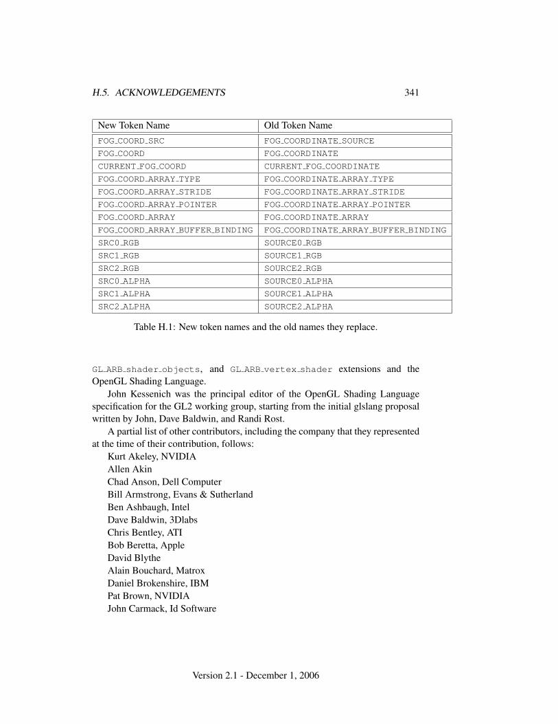
H.5. ACKNOWLEDGEMENTS 341
New Token Name Old Token NameFOG COORD SRC FOG COORDINATE SOURCE
FOG COORD FOG COORDINATE
CURRENT FOG COORD CURRENT FOG COORDINATE
FOG COORD ARRAY TYPE FOG COORDINATE ARRAY TYPE
FOG COORD ARRAY STRIDE FOG COORDINATE ARRAY STRIDE
FOG COORD ARRAY POINTER FOG COORDINATE ARRAY POINTER
FOG COORD ARRAY FOG COORDINATE ARRAY
FOG COORD ARRAY BUFFER BINDING FOG COORDINATE ARRAY BUFFER BINDING
SRC0 RGB SOURCE0 RGB
SRC1 RGB SOURCE1 RGB
SRC2 RGB SOURCE2 RGB
SRC0 ALPHA SOURCE0 ALPHA
SRC1 ALPHA SOURCE1 ALPHA
SRC2 ALPHA SOURCE2 ALPHA
Table H.1: New token names and the old names they replace.
GL ARB shader objects, and GL ARB vertex shader extensions and theOpenGL Shading Language.
John Kessenich was the principal editor of the OpenGL Shading Languagespecification for the GL2 working group, starting from the initial glslang proposalwritten by John, Dave Baldwin, and Randi Rost.
A partial list of other contributors, including the company that they representedat the time of their contribution, follows:
Kurt Akeley, NVIDIAAllen AkinChad Anson, Dell ComputerBill Armstrong, Evans & SutherlandBen Ashbaugh, IntelDave Baldwin, 3DlabsChris Bentley, ATIBob Beretta, AppleDavid BlytheAlain Bouchard, MatroxDaniel Brokenshire, IBMPat Brown, NVIDIAJohn Carmack, Id Software
Version 2.1 - December 1, 2006
342 APPENDIX H. VERSION 1.5
Paul Carmichael, NVIDIABob Carwell, IBMPaul Clarke, IBMBill Clifford, IntelRoger Cloud, SGIGraham Connor, Power VRMatt Craighead, NVIDIADoug Crisman, SGIMatt Cruikshank, Vital ImagesDeron Dann Johnson, SunSuzy Deffeyes, IBMSteve Demlow, Vital ImagesJoe Deng, SiSJean-Luc Dery, DiscreetKenneth Dyke, AppleBrian Emberling, SunCass Everitt, NVIDIABrandon Fliflet, IntelAllen Gallotta, ATIDaniel Ginsburg, ATISteve Glanville, NVIDIAPeter Graffagnino, AppleLee Gross, IBMRick Hammerstone, ATIEvan Hart, ATIChris Hecker, Definition 6Alan Heirich, HPGareth Hughes, NVIDIAMichael I Gold, NVIDIAJohn Jarvis, Alt.softwareRich Johnson, HPJohn Kessenich, 3DlabsMark Kilgard, NVIDIADale Kirkland, 3DlabsRaymond Klassen, IntelJason Knipe, BiowareJayant Kolhe, NVIDIASteve Koren, 3DlabsBob Kuehne, SGIChristian Laforte, Alias
Version 2.1 - December 1, 2006
H.5. ACKNOWLEDGEMENTS 343
Luc Leblanc, DiscreetJon Leech, SGIKevin Lefebvre, HPBill Licea-Kane, ATIBarthold Lichtenbelt, 3DlabsKent Lin, IntelBenjamin Lipchak, ATIRob Mace, ATIBill Mark, NVIDIAMichael McCool, U. WaterlooJack Middleton, SunHoward Miller, AppleTeri Morrison, HP / 3DlabsMarc Olano, SGI / U. MarylandJean-Francois Panisset, DiscreetJon Paul Schelter, MatroxBrian Paul, Tungsten GraphicsScott Peterson, HPBimal Poddar, IntelThomas Roell, Xi GraphicsPhil Rogers, ATIIan Romanick, IBMJohn Rosasco, AppleRandi Rost, 3DlabsMatt Russo, MatroxJeremy Sandmel, ATIPaul Sargent, 3DlabsFolker Schamel, Spinor GMBHMichael Schulman, SunJohn Scott, Raven SoftwareAvinash Seetharamaiah, IntelJohn Spitzer, NVIDIAVlad Stamate, Power VRMichelle Stamnes, IntelJohn Stauffer, AppleEskil Steenberg, ObsessionBruce Stockwell, HPChristopher Tan, IBMRay Tice, AvidPierre P. Tremblay, Discreet
Version 2.1 - December 1, 2006
344 APPENDIX H. VERSION 1.5
Neil Trevett, 3DlabsNick Triantos, NVIDIADouglas Twilleager, SunShawn Underwood, SGISteve Urquhart, IntelligraphicsVictor Vedovato, ATIDaniel Vogel, Epic GamesMik Wells, SoftimageHelene Workman, AppleDave Zenz, DellKarel Zuiderveld, Vital Images
Version 2.1 - December 1, 2006
Appendix I
Version 2.0
OpenGL version 2.0, released on September 7, 2004, is the sixth revision since theoriginal version 1.0. Despite incrementing the major version number (to indicatesupport for high-level programmable shaders), version 2.0 is upward compatiblewith earlier versions, meaning that any program that runs with a 1.5, 1.4, 1.3, 1.2,1.1, or 1.0 GL implementation will also run unchanged with a 2.0 GL implemen-tation.
Following are brief descriptions of each addition to OpenGL 2.0.
I.1 Programmable Shading
The OpenGL Shading Language, and the related APIs to create, manage, and useprogrammable shaders written in the Shading Language, were promoted to corefeatures in OpenGL 2.0. The complete list of features related to programmableshading includes:
I.1.1 Shader Objects
Shader objects provides mechanisms necessary to manage shader and program ob-jects. Shader objects were promoted from the GL ARB shader objects exten-sion.
I.1.2 Shader Programs
Vertex and fragment shader programs may be written in the high-level OpenGLShading Language, replacing fixed-functionality vertex and fragment process-ing respectively. Vertex and fragment shader programs were promoted from theGL ARB vertex shader and GL ARB fragment shader extensions.
345
346 APPENDIX I. VERSION 2.0
I.1.3 OpenGL Shading Language
The OpenGL Shading Language is a high-level, C-like language used to programthe vertex and fragment pipelines. The Shading Language Specification definesthe language proper, while OpenGL API features control how vertex and fragmentprograms interact with the fixed-function OpenGL pipeline and how applicationsmanage those programs.
OpenGL 2.0 implementations must support at least revision 1.10of the OpenGL Shading Language. Implementations may query theSHADING LANGUAGE VERSION string to determine the exact version of thelanguage supported. The OpenGL Shading Language was promoted from theGL ARB shading language 100 extension (the shading language itself isspecified in a companion document; due to the way it’s written, that document didnot need to be changed as a consequence of promoting programmable shading tothe OpenGL core).
I.1.4 Changes To Shader APIs
Small changes to the APIs for managing shader and program objects were madein the process of promoting the shader extensions to the OpenGL 2.0 core. Thesechanges do not affect the functionality of the shader APIs, but include use of theexisting uint core GL type rather than the new handleARB type introduced bythe extensions, and changes in some function names, for example mapping the ex-tension function CreateShaderObjectARB into the core function CreateShader.
I.2 Multiple Render Targets
Programmable shaders may write different colors to multiple output colorbuffers in a single pass. Multiple render targets was promoted from theGL ARB draw buffers extension.
I.3 Non-Power-Of-Two Textures
The restriction of textures to power-of-two dimensions has been relaxed forall texture targets, so that non-power-of-two textures may be specified with-out generating errors. Non-power-of-two textures was promoted from theGL ARB texture non power of two extension.
Version 2.1 - December 1, 2006

I.4. POINT SPRITES 347
I.4 Point Sprites
Point sprites replace point texture coordinates with texture coordinates interpolatedacross the point. This allows drawing points as customized textures, useful forparticle systems.
Point sprites were promoted from the GL ARB point sprite extension, withthe further addition of the POINT SPRITE COORD ORIGIN parameter controllingthe direction in which the t texture coordinate increases.
I.5 Separate Blend Equation
Blending capability is extended with BlendEquationSeparate to allow indepen-dent setting of the RGB and alpha blend equations for blend operations.
Separate blend functions was pro-moted from the GL EXT blend equation separate extension. Note that blendequation LOGIC OP is not supported unless the GL EXT blend logic op exten-sion is supported; LOGIC OP was inadvertently included in the initial release of theOpenGL 2.0 Specification.
I.6 Separate Stencil
Separate stencil functionality may be defined for the front and back faces of primi-tives, improving performance of shadow volume and Constructive Solid Geometryrendering algorithms.
Separate stencil was based on the theAPI of the GL ATI separate stencil extension, with additional state definedby the similar GL EXT stencil two side extension.
I.7 Other Changes
Several minor revisions and corrections to the OpenGL 1.5 specification weremade:
• In section 2.7, SecondaryColor3 was changed to set A to 1.0 (previously0.0), so the initial GL state can be restored.
• In section 2.13, transformation was added to the list of steps not performedby WindowPos.
Version 2.1 - December 1, 2006
348 APPENDIX I. VERSION 2.0
• Section 3.8.1 was clarified to mandate that selection of texture internal for-mat must allocate a non-zero number of bits for all components named bythe internal format, and zero bits for all other components.
• Tables 3.21 and 3.22 were generalized to multiple textures by replacing Cf
with Cp.
• In section 6.1.9, GetHistogram was clarified to note that the Final Conver-sion pixel storage mode is not applied when storing histogram counts.
• The FOG COORD ARRAY BUFFER BINDING enumerant alias was added to ta-ble H.1.
After the initial version of the OpenGL 2.0 was released, several more minorcorrections were made in the specification revision approved on October 22, 2004:
• Corrected name of the fog source from FOG COORD SRC to FOG COORD insection 2.13.
• Corrected last parameter type in the declaration of the UniformMatrix*commands to const float *value, in section 2.15.3.
• Changed the end of the second paragraph of the Conversion to Fragmentssubsection of section 3.6.4, to more clearly describe the set of generatedfragments.
• Changed from the older FOG COORDINATE to the newer FOG COORD notationin section 3.10.
• Added POINT SPRITE COORD ORIGIN state to table 6.14.
• Changed the description of MAX TEXTURE UNITS in table 6.35 to reflect itslegacy status (referring to the number of fixed-function texture units), andmoved it into table 6.36.
• Removed duplicated table entries for MAX TEXTURE IMAGE UNITS andMAX TEXTURE COORDS from table 6.36.
• Added Victor Vedovato to the OpenGL 2.0 Acknowledgements section.
• Miscellaneous typographical corrections.
Additional minor corrections were made in the specification revision approvedon February 9, 2005:
Version 2.1 - December 1, 2006

I.8. ACKNOWLEDGEMENTS 349
• Restored missing language from the depth texture extension in section 6.1.4,allowing DEPTH COMPONENT as a format for texture readbacks.
• Added separate blend equation to the feature list in appendix I. The featurehas been in the actual OpenGL 2.0 specification all along, but was omittedfrom the feature list in the initial specification release.
• Removed LOGIC OP from the allowed blend equations in section 4.1.8 andtable 4.1, and adjusted the type of the blend equation state in table 6.21accordingly.
• Restored missing VERTEX ATTRIB ARRAY BUFFER BINDING state from ta-ble 6.8.
• Miscellaneous typographical corrections.
I.8 Acknowledgements
OpenGL 2.0 is the result of the contributions of many people. The editors espe-cially thank the ongoing work of the ARB GL2 working group, led by Bill Licea-Kane and with specifications edited by John Kessenich and Barthold Lichtenbelt,in performing work necessary to promote the OpenGL Shading Language to a coreOpenGL feature.
A partial list of other contributors, including the company that they representedat the time of their contribution, follows:
Kurt Akeley, NVIDIAAllen AkinDave Baldwin, 3DlabsBob Beretta, ApplePat Brown, NVIDIAMatt Craighead, NVIDIASuzy Deffeyes, IBMKen Dyke, AppleCass Everitt, NVIDIASteve Glanville, NVIDIAMichael I. Gold, NVIDIAEvan Hart, ATIPhil Huxley, 3DlabsDeron Dann Johnson, SunJohn Kessenich, 3DlabsMark Kilgard, NVIDIA
Version 2.1 - December 1, 2006
350 APPENDIX I. VERSION 2.0
Dale Kirkland, 3DlabsSteve Koren, 3DlabsJon Leech, SGIBill Licea-Kane, ATIBarthold Lichtenbelt, 3DlabsKent Lin, IntelBenjamin Lipchak, ATIRob Mace, ATIMichael McCool, U. WaterlooJack Middleton, SunJeremy Morris, 3DlabsTeri Morrison, 3DlabsMarc Olano, SGI / U. MarylandGlenn Ortner, ATIBrian Paul, Tungsten GraphicsBimal Poddar, IntelPhil Rogers, ATIIan Romanick, IBMRandi Rost, 3DlabsJeremy Sandmel, ATIFolker Schamel, Spinor GMBHGeoff Stahl, AppleEskil Steenberg, ObsessionNeil Trevett, 3DlabsVictor Vedovato, ATIMik Wells, SoftimageEsen Yilmaz, IntelDave Zenz, Dell
Version 2.1 - December 1, 2006
Appendix J
Version 2.1
OpenGL version 2.1, released on August 2, 2006, is the seventh revision since theoriginal version 1.0. Despite incrementing the major version number (to indicatesupport for high-level programmable shaders), version 2.1 is upward compatiblewith earlier versions, meaning that any program that runs with a 2.0, 1.5, 1.4,1.3, 1.2, 1.1, or 1.0 GL implementation will also run unchanged with a 2.0 GLimplementation.
Following are brief descriptions of each addition to OpenGL 2.1.
J.1 OpenGL Shading Language
OpenGL 2.1 implementations must support at least revision 1.20 ofthe OpenGL Shading Language. Implementations may query theSHADING LANGUAGE VERSION string to determine the exact version of thelanguage supported. Refer to the OpenGL Shading Language Specification fordetails of the changes between revision 1.10 and 1.20.
J.2 Non-Square Matrices
Added the UniformMatrix{2x3,3x2,2x4,4x2,3x4,4x3}fv commands in sec-tion 2.15.3, allowing specification of non-square uniform matrices.
J.3 Pixel Buffer Objects
Pixel buffer objects expand on the interface provided by the vertex buffer objects,allowing buffer objects to be used with both vertex array and pixel data. This allows
351
352 APPENDIX J. VERSION 2.1
more acceleration opportunities for OpenGL pixel commands.When a buffer object is bound to the PIXEL PACK BUFFER target, commands
such as ReadPixels write their data into a buffer object. When a buffer object isbound to the PIXEL UNPACK BUFFER target, commands such as DrawPixels andTexImage2D read their data from a buffer object.
Pixel buffer objects was promoted from the GL ARB pixel buffer object
extension. The specification was tightened to consistently require error be gener-ated when read or write operations to a pixel buffer object would run past the endof the buffer, or would be misaligned with respect to the data type being read orwritten.
J.4 sRGB Textures
New uncompressed and compressed color texture formats with sRGB color com-ponents are defined. The sRGB color space is based on typical (non-linear) monitorcharacteristics expected in a dimly lit office. It has been standardized by the Inter-national Electrotechnical Commission (IEC) as IEC 61966-2-1. The sRGB colorspace roughly corresponds to 2.2 gamma correction.
sRGB textures was promoted from the GL EXT texture sRGB extension.Specific compressed sRGB internal formats defined by the extension were not in-cluded in OpenGL 2.1, while the generic uncompressed and compressed formatswere retained
J.5 Other Changes
Several minor revisions and corrections to the OpenGL 2.0 specification weremade:
• Note that the information log for program objects can include both link andvalidation information, in section 2.15.2.
• Noted in section 3.6.4 that there is a current raster secondary color, and addedthe CURRENT RASTER SECONDARY COLOR query.
• Required perspective-correct interpolation forall fragment attributes except depth in sections 3.4.1 and 3.5.1, effectivelymaking GL PERSPECTIVE CORRECT HINT a no-op.
• Merged specific and generic compressed internal texture format tables intothe single table 3.17.
Version 2.1 - December 1, 2006
J.5. OTHER CHANGES 353
• Changed the type of texture wrap mode and min/mag filter parameters frominteger to enum in table 3.18.
• Removed mention of compressed texture depth components from sec-tion 3.8.1, since no compressed depth formats are currently defined.
• Added forward reference from section 3.8.5 to section 3.8.14, which defineshow depth textures are actually used.
• Remove c notation in table 4.1, and fixed blend equations forFUNC REVERSE SUBTRACT.
• Noted in section 6.1.15 that all texture object parameters are pushed andpopped by PushAttrib and PopAttrib when TEXTURE BIT is set in the at-tribute mask.
• Miscellaneous typographical corrections.
Additional minor corrections were made in a specification revision approved onAugust 10, 2006, with a few additional fixes and omissions corrected on December1, 2006:
• Noted in section 2.5 that INVALID VALUE is generated for negativesizeiptr values.
• Noted in section 2.7 that VertexAttrib* can be used to load attributes forany supported matrix type, not just square matrices.
• Removed the description of generating multiple connected componentswhen clipping vertices with wc values of different signs, at the end of sec-tion 2.12. Implementations should not render in the wc < 0 region.
• Added FLOAT MAT2x3, FLOAT MAT2x4, FLOAT MAT3x2, FLOAT MAT3x4,FLOAT MAT4x2, and FLOAT MAT4x3 tokens for non-square matrix types toGetActiveAttrib and GetActiveUniform in section 2.15.3, and expandedthe description of how attribute components are mapped to matrix elementsto match.
• Clarified in section 3.8.12 that the texture object passed to BindTexture mustmatch the specified target, not just the dimensionality of target.
• Added missing TexEnv targets RGB SCALE, ALPHA SCALE, SRCn RGB,SRCn ALPHA, OPERANDn RGB, and OPERANDn ALPHA in section 3.8.13.
Version 2.1 - December 1, 2006
354 APPENDIX J. VERSION 2.1
• Noted that POINT SPRITE is a possible env parameter to GetTexEnv in sec-tion 6.1.3.
• Miscellaneous typographical corrections.
J.6 Acknowledgements
OpenGL 2.1 is the result of the contributions of many people. The editor especiallythanks the ongoing work of the ARB GLSL working group, led by Bill Licea-Kaneand with specifications edited by John Kessenich and Barthold Lichtenbelt, in up-dating the OpenGL Shading Language to revision 1.20. Ralf Biermann, Derek Cor-nish, Matt Craighead, and Mark Kilgard edited the EXT pixel buffer object
proposal later adopted and developed by the ARB Pixel Buffer Object workinggroup, and Mark Kilgard edited the EXT texture sRGB extension.
A partial list of other contributors, including the company that they representedat the time of their contribution, follows:
Aaftab Munshi, ATIAvi Shapira, Graphic RemedyBarthold Lichtenbelt, 3Dlabs / NVIDIABenjamin Lipchak, ATIBenji Bowman, Imagination TechnologiesBill Armstrong, Evans and SutherlandBill Licea-Kane, ATIBimal Poddar, IntelBob Beretta, AppleBrian Paul, Tungsten GraphicsCass Everitt, NVIDIAChris Dodd, NVIDIAChris Starkey, 3DlabsDale Kirkland, 3DlabsDaniel Vogel, Epic GamesDave Shreiner, SGIDerek Cornish, NVIDIAEskil Steenberg, ObsessionEvan Hart, ATIFolker Schamel, Spinor GMBHGeoff Stahl, AppleHoward Miller, AppleIan Romanick, IBM
Version 2.1 - December 1, 2006
J.6. ACKNOWLEDGEMENTS 355
James A. McCombe, AppleJeff Juliano, NVIDIAJeff Weyman, ATIJeremy Sandmel, Apple / ATIJohn Kessenich, 3Dlabs / IntelJohn Rosasco, AppleJohn ScottJon Leech, SGIJon Trulson, Xi GraphicsKen Severson, NVIDIAKenneth Dyke, AppleKenneth Russell, SunKent Lin, IntelMarc Olano, U. MarylandMark Kilgard, NVIDIAMichael Gold, NVIDIANeeraj Srivastava, DellNeil Trevett, 3Dlabs / NVIDIANick Burns, ApplePat Brown, NVIDIAPaul Martz, SimAuthorPaul Ramsey, SunPierre Boudier, ATIRalf Biermann, NVIDIARandi Rost, 3DlabsRob Mace, ATIRobert Simpson, Bitboys / ATISaifuddin Fakhruddin, IntelShawn Underwood, SGISteve Demlow, Vital ImagesSteve Koren, 3DlabsSteven Zhu, IntelThomas Roell, NVIDIATom Lanzoni, DellTravis Bryson, SunYaki Tebeka, Graphic Remedy
Version 2.1 - December 1, 2006
Appendix K
ARB Extensions
OpenGL extensions that have been approved by the OpenGL Architectural ReviewBoard (ARB) are described in this chapter. These extensions are not required to besupported by a conformant OpenGL implementation, but are expected to be widelyavailable; they define functionality that is likely to move into the required featureset in a future revision of the specification.
In order not to compromise the readability of the core specification, ARB ex-tensions are not integrated into the core language; instead, they are made availableonline in the OpenGL Extension Registry (as are a much larger number of vendor-specific extensions, as well as extensions to GLX and WGL). Extensions are doc-umented as changes to the Specification. The Registry is available on the WorldWide Web at URL
http://www.opengl.org/registry/
Brief descriptions of ARB extensions are provided below.
K.1 Naming Conventions
To distinguish ARB extensions from core OpenGL features and from vendor-specific extensions, the following naming conventions are used:
• A unique name string of the form "GL ARB name" is associated with eachextension. If the extension is supported by an implementation, this stringwill be present in the EXTENSIONS string described in section 6.1.11.
• All functions defined by the extension will have names of the form Func-tionARB
356
K.2. PROMOTING EXTENSIONS TO CORE FEATURES 357
• All enumerants defined by the extension will have names of the formNAME ARB.
• In additional to OpenGL extensions, there are also ARB extensions to therelated GLX and WGL APIs. Such extensions have name strings prefixed by"GLX " and "WGL " respectively. Not all GLX and WGL ARB extensionsare described here, but all such extensions are included in the registry.
K.2 Promoting Extensions to Core Features
ARB extensions can be promoted to required core features in later revisions ofOpenGL. When this occurs, the extension specifications are merged into the corespecification. Functions and enumerants that are part of such promoted extensionswill have the ARB affix removed.
GL implementations of such later revisions should continue to export the namestrings of promoted extensions in the EXTENSIONS string, and continue to supportthe ARB-affixed versions of functions and enumerants as a transition aid.
For descriptions of extensions promoted to core features in OpenGL 1.3 andbeyond, see appendices F, G, H, and I respectively.
K.3 Multitexture
The name string for multitexture is GL ARB multitexture. It was promoted to acore feature in OpenGL 1.3.
K.4 Transpose Matrix
The name string for transpose matrix is GL ARB transpose matrix. It was pro-moted to a core feature in OpenGL 1.3.
K.5 Multisample
The name string for multisample is GL ARB multisample. It was promoted to acore feature in OpenGL 1.3.
Version 2.1 - December 1, 2006
358 APPENDIX K. ARB EXTENSIONS
K.6 Texture Add Environment Mode
The name string for texture add mode is GL ARB texture env add. It was pro-moted to a core feature in OpenGL 1.3.
K.7 Cube Map Textures
The name string for cube mapping is GL ARB texture cube map. It was pro-moted to a core feature in OpenGL 1.3.
K.8 Compressed Textures
The name string for compressed textures is GL ARB texture compression. Itwas promoted to a core feature in OpenGL 1.3.
K.9 Texture Border Clamp
The name string for texture border clamp is GL ARB texture border clamp. Itwas promoted to a core feature in OpenGL 1.3.
K.10 Point Parameters
The name string for point parameters is GL ARB point parameters. It was pro-moted to a core features in OpenGL 1.4.
K.11 Vertex Blend
Vertex blending replaces the single model-view transformation with multiple ver-tex units. Each unit has its own transform matrix and an associated current weight.Vertices are transformed by all the enabled units, scaled by their respective weights,and summed to create the eye-space vertex. Normals are similarly transformed bythe inverse transpose of the model-view matrices.
The name string for vertex blend is GL ARB vertex blend.
Version 2.1 - December 1, 2006
K.12. MATRIX PALETTE 359
K.12 Matrix Palette
Matrix palette extends vertex blending to include a palette of model-view matrices.Each vertex may be transformed by a different set of matrices chosen from thepalette.
The name string for matrix palette is GL ARB matrix palette.
K.13 Texture Combine Environment Mode
The name string for texture combine mode is GL ARB texture env combine. Itwas promoted to a core feature in OpenGL 1.3.
K.14 Texture Crossbar Environment Mode
The name string for texture crossbar is GL ARB texture env crossbar. It waspromoted to a core features in OpenGL 1.4.
K.15 Texture Dot3 Environment Mode
The name string for DOT3 is GL ARB texture env dot3. It was promoted to acore feature in OpenGL 1.3.
K.16 Texture Mirrored Repeat
The name string for texture mirrored repeat isGL ARB texture mirrored repeat. It was promoted to a core feature inOpenGL 1.4.
K.17 Depth Texture
The name string for depth texture is GL ARB depth texture. It was promoted toa core feature in OpenGL 1.4.
K.18 Shadow
The name string for shadow is GL ARB shadow. It was promoted to a core featurein OpenGL 1.4.
Version 2.1 - December 1, 2006
360 APPENDIX K. ARB EXTENSIONS
K.19 Shadow Ambient
Shadow ambient extends the basic image-based shadow functionality by allowinga texture value specified by the TEXTURE COMPARE FAIL VALUE ARB texture pa-rameter to be returned when the texture comparison fails. This may be used forambient lighting of shadowed fragments and other advanced lighting effects.
The name string for shadow ambient is GL ARB shadow ambient.
K.20 Window Raster Position
The name string for window raster position is GL ARB window pos. It was pro-moted to a core feature in OpenGL 1.4.
K.21 Low-Level Vertex Programming
Application-defined vertex programs may be specified in a new low-level program-ming language, replacing the standard fixed-function vertex transformation, light-ing, and texture coordinate generation pipeline. Vertex programs enable many neweffects and are an important first step towards future graphics pipelines that will befully programmable in an unrestricted, high-level shading language.
The name string for low-level vertex programming isGL ARB vertex program.
K.22 Low-Level Fragment Programming
Application-defined fragment programs may be specified in the same low-level lan-guage as GL ARB vertex program, replacing the standard fixed-function vertextexturing, fog, and color sum operations.
The name string for low-level fragment programming isGL ARB fragment program.
K.23 Buffer Objects
The name string for buffer objects is GL ARB vertex buffer object. It waspromoted to a core feature in OpenGL 1.5.
Version 2.1 - December 1, 2006
K.24. OCCLUSION QUERIES 361
K.24 Occlusion Queries
The name string for occlusion queries is GL ARB occlusion query. It was pro-moted to a core feature in OpenGL 1.5.
K.25 Shader Objects
The name string for shader objects is GL ARB shader objects. It was promotedto a core feature in OpenGL 2.0.
K.26 High-Level Vertex Programming
The name string for high-level vertex programming is GL ARB vertex shader.It was promoted to a core feature in OpenGL 2.0.
K.27 High-Level Fragment Programming
The name string for high-level fragmentprogramming is GL ARB fragment shader. It was promoted to a core featurein OpenGL 2.0.
K.28 OpenGL Shading Language
The name string for the OpenGL Shading Language isGL ARB shading language 100. The presence of this extension string in-dicates that programs written in version 1 of the Shading Language are acceptedby OpenGL.
It was promoted to a core feature in OpenGL 2.0.
K.29 Non-Power-Of-Two Textures
The name string for non-power-of-two textures isGL ARB texture non power of two. It was promoted to a core feature inOpenGL 2.0.
Version 2.1 - December 1, 2006
362 APPENDIX K. ARB EXTENSIONS
K.30 Point Sprites
The name string for point sprites is GL ARB point sprite. It was promoted to acore feature in OpenGL 2.0.
K.31 Fragment Program Shadow
Fragment program shadow extends low-level fragment programs defined withGL ARB fragment program to add shadow 1D, 2D, and 3D texture targets, andremove the interaction with GL ARB shadow.
The name string for fragment program shadow isGL ARB fragment program shadow.
K.32 Multiple Render Targets
The name string for multiple render targets is GL ARB draw buffers. It waspromoted to a core feature in OpenGL 2.0.
K.33 Rectangular Textures
Rectangular textures define a new texture target TEXTURE RECTANGLE ARB thatsupports 2D textures without requiring power-of-two dimensions. Rectangulartextures are useful for storing video images that do not have power-of-two sizes(POTS). Resampling artifacts are avoided and less texture memory may be re-quired. They are are also useful for shadow maps and window-space texturing.These textures are accessed by dimension-dependent (aka non-normalized) texturecoordinates.
Rectangular textures are a restricted version of non-power-of-two textures. Thedifferences are that rectangular textures are supported only for 2D; they require anew texture target; and the new target uses non-normalizes texture coordinates
The name string for texture rectangles is GL ARB texture rectangle.
K.34 Floating-Point Color Buffers
Floating-point color buffers can represent values outside the normal [0, 1] rangeof colors in the fixed-function OpenGL pipeline. This group of related exten-sions enables controlling clamping of vertex colors, fragment colors throughout thepipeline, and pixel data read back to client memory, and also includes WGL and
Version 2.1 - December 1, 2006
K.35. HALF-PRECISION FLOATING POINT 363
GLX extensions for creating frame buffers with floating-point color components(referred to in GLX as framebuffer configurations, and in WGL as pixel formats).
The name strings for floating-point color buffers areGL ARB color buffer float, GLX ARB fbconfig float, andWGL ARB pixel format float.
K.35 Half-Precision Floating Point
This extension defines the representation of a 16-bit floating point data format, anda corresponding type argument which may be used to specify and read back pixeland texture images stored in this format in client memory. Half-precision floats aresmaller than full precision floats, but provide a larger dynamic range than similarlysized (short) data types.
The name string for half-precision floating point isGL ARB half float pixel.
K.36 Floating-Point Textures
Floating-point textures stored in both 32- and 16-bit formats may be defined usingnew internalformat arguments to commands which specify and read back textureimages.
The name string for floating-point textures is GL ARB texture float.
K.37 Pixel Buffer Objects
The buffer object interface is expanded by adding two new binding targets forbuffer objects, the pixel pack and unpack buffers. This permits buffer objects to beused to store pixel data as well as vertex array data. Pixel-drawing and -readingcommands using data in pixel buffer objects may operate at greatly improved per-formance compared to data in client memory.
The name string for pixel buffer objects is GL ARB pixel buffer object. Itwas promoted to a core feature in OpenGL 2.1.
Version 2.1 - December 1, 2006
Index
x BIAS, 117, 288x SCALE, 117, 2882D, 240, 241, 3032 BYTES, 2433D, 240, 2413D COLOR, 240, 2413D COLOR TEXTURE, 240, 2413 BYTES, 2434D COLOR TEXTURE, 240, 2414 BYTES, 243
1, 152, 161, 180, 253, 2812, 152, 161, 253, 2813, 152, 161, 253, 2814, 152, 161, 253
ACCUM, 220, 221Accum, 220, 221ACCUM BUFFER BIT, 219, 265ACTIVE ATTRIBUTE MAX LENGTH,
77, 261ACTIVE ATTRIBUTES, 77, 261ACTIVE TEXTURE, 21, 47, 55, 184,
232, 248, 249ACTIVE UNIFORM MAX LENGTH,
81, 261ACTIVE UNIFORMS, 80, 261ActiveTexture, 47, 83, 192ADD, 185, 187, 188, 220, 221, 327ADD SIGNED, 188ALL ATTRIB BITS, 264, 265ALPHA, 117, 130, 141, 142, 152, 154,
155, 169, 170, 185–187, 190,211, 224, 226, 251, 253, 288,289, 291, 302, 312, 318
ALPHA12, 154
ALPHA16, 154ALPHA4, 154ALPHA8, 154ALPHA BIAS, 139ALPHA SCALE, 139, 185, 353ALPHA TEST, 204AlphaFunc, 204ALWAYS, 169, 190, 204–207, 285AMBIENT, 65, 66, 68AMBIENT AND DIFFUSE, 65, 66, 68AND, 214AND INVERTED, 214AND REVERSE, 214Antialiasing, 107AreTexturesResident, 183, 244ARRAY BUFFER, 33, 35–39, 259, 260ARRAY BUFFER BINDING, 38ArrayElement, 19, 27–29, 38, 242ATTACHED SHADERS, 261, 262AttachShader, 74, 244AUTO NORMAL, 85, 233AUXi, 215, 216AUXm, 215, 216AUXn, 224AUX0, 215, 216, 224
BACK, 64, 66, 67, 108, 109, 111, 205,215–218, 224, 249, 279
BACK LEFT, 215, 216, 224BACK RIGHT, 215, 216, 224Begin, 12, 15–20, 28, 29, 40, 64, 68, 70,
87, 101, 105, 108, 111, 234,235, 240
BeginQuery, 207, 208BGR, 130, 224, 226, 251BGRA, 130, 132, 136, 224, 251, 316
364
INDEX 365
BindAttribLocation, 78, 244BindBuffer, 33, 39, 244BindTexture, 47, 83, 182, 183, 353BITMAP, 110, 118, 121, 127, 129, 136,
149, 226, 253Bitmap, 149BITMAP TOKEN, 241BLEND, 185, 187, 209, 213BlendColor, 212, 334BlendEquation, 209, 334BlendEquationSeparate, 209, 347BlendFunc, 211, 334BlendFuncSeparate, 211, 335BLUE, 117, 130, 224, 226, 251, 288,
289, 291, 302BLUE BIAS, 139BLUE SCALE, 139BOOL, 81BOOL VEC2, 81BOOL VEC3, 81BOOL VEC4, 81BUFFER ACCESS, 34, 36, 37BUFFER MAP POINTER, 34, 36–38,
260BUFFER MAPPED, 34, 36–38BUFFER SIZE, 34, 36BUFFER USAGE, 34, 36, 37BufferData, 35, 36, 244BufferSubData, 36, 37, 244bvec2, 82BYTE, 24, 129, 226, 227, 243
C3F V3F, 31, 32C4F N3F V3F, 31, 32C4UB V2F, 31, 32C4UB V3F, 31, 32CallList, 19, 242, 243CallLists, 19, 242, 243CCW, 63, 64, 279CLAMP, 169, 171CLAMP TO BORDER, 169, 172, 327CLAMP TO EDGE, 169, 171, 172, 317CLEAR, 214Clear, 219, 220ClearAccum, 219
ClearColor, 219ClearDepth, 219ClearIndex, 219ClearStencil, 219CLIENT ACTIVE TEXTURE, 26, 248,
249CLIENT ALL ATTRIB BITS, 264, 265CLIENT PIXEL STORE BIT, 265CLIENT VERTEX ARRAY BIT, 265ClientActiveTexture, 20, 26, 244CLIP PLANEi, 52, 53CLIP PLANE0, 53ClipPlane, 52COEFF, 251COLOR, 43, 47, 48, 120, 124, 125, 161,
229Color, 19, 21, 22, 57, 68, 71, 76Color3, 21Color4, 21Color[size][type]v, 27COLOR ARRAY, 26, 31COLOR ARRAY POINTER, 257COLOR BUFFER BIT, 219, 220, 265COLOR INDEX, 110, 118, 121, 127,
130, 140, 149, 224, 229, 252,253
COLOR INDEXES, 65, 69COLOR LOGIC OP, 213COLOR MATERIAL, 66, 68COLOR MATRIX, 254COLOR MATRIX STACK DEPTH,
254COLOR SUM, 194COLOR TABLE, 119, 121, 140COLOR TABLE ALPHA SIZE, 254COLOR TABLE BIAS, 118, 119, 254COLOR TABLE BLUE SIZE, 254COLOR TABLE FORMAT, 254COLOR TABLE GREEN SIZE, 254COLOR TABLE INTENSITY SIZE,
254COLOR TABLE LUMINANCE SIZE,
254COLOR TABLE RED SIZE, 254
Version 2.1 - December 1, 2006
366 INDEX
COLOR TABLE SCALE, 118–120,254
COLOR TABLE WIDTH, 254ColorMask, 217, 218ColorMaterial, 66–68, 233, 309, 314ColorPointer, 19, 24, 25, 31, 244ColorSubTable, 115, 120ColorTable, 115, 118–121, 145, 146, 244ColorTableParameter, 119ColorTableParameterfv, 118Colorub, 71Colorui, 71Colorus, 71COMBINE, 185, 188, 192, 327, 335COMBINE ALPHA, 185, 188, 189COMBINE RGB, 185, 188, 189COMPARE R TO TEXTURE, 169,
190COMPILE, 242, 309COMPILE AND EXECUTE, 242, 243COMPILE STATUS, 73, 260CompileShader, 73, 244COMPRESSED ALPHA, 155COMPRESSED INTENSITY, 155COMPRESSED LUMINANCE, 155COMPRESSED LUMINANCE ALPHA,
155COMPRESSED RGB, 155COMPRESSED RGBA, 155COMPRESSED SLUMINANCE, 155,
191COMPRESSED SLUMINANCE ALPHA,
155, 191COMPRESSED SRGB, 155, 191COMPRESSED SRGB ALPHA, 155,
191COMPRESSED TEXTURE FORMATS,
153CompressedTexImage, 167CompressedTexImage1D, 165–167CompressedTexImage2D, 165–167CompressedTexImage3D, 165–167CompressedTexSubImage1D, 166–168CompressedTexSubImage2D, 166–168CompressedTexSubImage3D, 167, 168
CONSTANT, 187, 189, 284CONSTANT ALPHA, 211, 334CONSTANT ATTENUATION, 65CONSTANT BORDER, 143, 144CONSTANT COLOR, 211, 334CONVOLUTION 1D, 122–124, 141,
158, 255CONVOLUTION 2D, 121–123, 141,
158, 255CONVOLUTION BORDER COLOR,
143, 255CONVOLUTION BORDER MODE,
143, 255CONVOLUTION FILTER BIAS, 122,
123, 255CONVOLUTION FILTER SCALE,
122–124, 255CONVOLUTION FORMAT, 255CONVOLUTION HEIGHT, 255CONVOLUTION WIDTH, 255ConvolutionFilter1D, 115, 122–124ConvolutionFilter2D, 115, 121–124ConvolutionParameter, 122, 143ConvolutionParameterfv, 122, 123, 143ConvolutionParameteriv, 123, 143COORD REPLACE, 96, 100COPY, 213, 214, 286COPY INVERTED, 214COPY PIXEL TOKEN, 241CopyColorSubTable, 120CopyColorTable, 120CopyConvolutionFilter1D, 124CopyConvolutionFilter2D, 123CopyPixels, 114, 116, 120, 124, 141,
161, 221, 226, 228, 239CopyTexImage1D, 141, 161, 163, 177CopyTexImage2D, 141, 159, 161, 163,
177CopyTexImage3D, 163CopyTexSubImage1D, 141, 162–165CopyTexSubImage2D, 141, 162, 164,
165CopyTexSubImage3D, 141, 162, 163,
165CreateProgram, 74, 244
Version 2.1 - December 1, 2006
INDEX 367
CreateShader, 72, 244, 346CreateShaderObjectARB, 346CULL FACE, 108CullFace, 108, 109, 113CURRENT BIT, 265CURRENT FOG COORD, 341CURRENT FOG COORDINATE, 341CURRENT QUERY, 258CURRENT RASTER SECONDARY COLOR,
352CURRENT RASTER TEXTURE COORDS,
55, 308CURRENT TEXTURE COORDS, 21CURRENT VERTEX ATTRIB, 263CW, 64
DECAL, 185, 186DECR, 206DECR WRAP, 206, 335DELETE STATUS, 73, 260, 261DeleteBuffers, 34, 244DeleteLists, 244DeleteProgram, 75, 244DeleteQueries, 208, 244DeleteShader, 73, 244DeleteTextures, 183, 244DEPTH, 118, 122, 125, 126, 161, 229,
288, 334DEPTH BIAS, 117, 139DEPTH BUFFER BIT, 219, 220, 265DEPTH COMPONENT, 86, 118, 121,
127, 130, 152–154, 190, 198,222, 225, 229, 251, 252, 254–256, 349
DEPTH COMPONENT16, 154DEPTH COMPONENT24, 154DEPTH COMPONENT32, 154DEPTH SCALE, 117, 139DEPTH TEST, 206DEPTH TEXTURE MODE, 169, 181,
190DepthFunc, 207DepthMask, 218, 222DepthRange, 42, 57, 248, 309DepthTest, 222
DetachShader, 74, 244dFdx, 246dFdy, 246DIFFUSE, 65, 66Disable, 47, 48, 51, 53, 59, 63, 66, 94–
96, 102, 104, 108, 110, 112,145–147, 191, 194, 203–206,209, 213, 232, 233
DisableClientState, 19, 26, 31, 33, 244DisableVertexAttribArray, 26, 244, 263DITHER, 213DOMAIN, 251DONT CARE, 246, 297DOT3 RGB, 188DOT3 RGBA, 188DOUBLE, 24, 27DRAW PIXEL TOKEN, 241DrawArrays, 28, 29, 38, 242DrawBuffer, 213, 215–218, 220DrawBuffers, 215–217DrawElements, 29, 30, 38, 39, 242, 318DrawPixels, 110, 113–116, 118, 121,
127–132, 136, 138, 141, 148,149, 151, 152, 221, 222, 226,229, 239, 352
DrawRangeElements, 30, 38, 39, 242,300
DST ALPHA, 211DST COLOR, 211, 334DYNAMIC COPY, 34, 36DYNAMIC DRAW, 34, 35DYNAMIC READ, 34, 36
EDGE FLAG ARRAY, 26, 31EDGE FLAG ARRAY POINTER, 257EdgeFlag, 19EdgeFlagPointer, 19, 24, 25, 244EdgeFlagv, 19, 27ELEMENT ARRAY BUFFER, 33, 35,
37–39, 259, 260EMISSION, 65, 66Enable, 47, 48, 51, 53, 59, 63, 66, 94–96,
102, 104, 108, 110, 112, 145–147, 191, 194, 203–206, 209,213, 232, 233, 247
Version 2.1 - December 1, 2006
368 INDEX
ENABLE BIT, 265EnableClientState, 19, 26, 31, 33, 244EnableVertexAttribArray, 26, 244, 263End, 12, 15–20, 28, 29, 40, 64, 68, 70,
101, 108, 111, 234, 235, 240EndList, 242EndQuery, 207, 208EQUAL, 169, 190, 205–207EQUIV, 214EVAL BIT, 265EvalCoord, 19, 232, 233EvalCoord1, 233–235EvalCoord1d, 234EvalCoord1f, 234EvalCoord2, 233, 235, 236EvalMesh1, 234EvalMesh2, 234, 235EvalPoint, 19EvalPoint1, 235EvalPoint2, 235EXP, 195, 196, 276EXP2, 195EXT pixel buffer object, 354EXT texture sRGB, 354EXTENSIONS, 116, 257, 258, 356, 357EYE LINEAR, 50–52, 250, 284EYE PLANE, 50, 51
FALSE, 19, 34, 36, 38, 61–63, 73–75,82, 88, 89, 96, 114, 115, 117,125, 126, 136, 139, 147, 148,169, 180, 183, 198, 204, 208,222, 224, 248, 253, 256–261,282
FASTEST, 246FEEDBACK, 237–239, 310FEEDBACK BUFFER POINTER, 257FeedbackBuffer, 238, 239, 244FILL, 111–113, 234, 279, 309, 312Finish, 244, 245, 308FLAT, 70, 309FLOAT, 24, 27, 31–33, 77, 81, 129, 225,
227, 243, 251, 252, 271, 272float, 76FLOAT MAT2, 77, 81
FLOAT MAT2x3, 77, 81, 353FLOAT MAT2x4, 77, 81, 353FLOAT MAT3, 77, 81FLOAT MAT3x2, 77, 81, 353FLOAT MAT3x4, 77, 81, 353FLOAT MAT4, 77, 81FLOAT MAT4x2, 77, 81, 353FLOAT MAT4x3, 77, 81, 353FLOAT VEC2, 77, 81FLOAT VEC3, 77, 81FLOAT VEC4, 77, 81Flush, 244, 245, 308FOG, 194Fog, 194, 195FOG BIT, 265FOG COLOR, 195FOG COORD, 55, 194, 195, 341, 348FOG COORD ARRAY, 26, 31, 341FOG COORD ARRAY BUFFER BINDING,
341, 348FOG COORD ARRAY POINTER,
257, 341FOG COORD ARRAY STRIDE, 341FOG COORD ARRAY TYPE, 341FOG COORD SRC, 57, 195, 196, 341,
348FOG COORDINATE, 341, 348FOG COORDINATE ARRAY, 341FOG COORDINATE ARRAY BUFFER BINDING,
341FOG COORDINATE ARRAY POINTER,
341FOG COORDINATE ARRAY STRIDE,
341FOG COORDINATE ARRAY TYPE,
341FOG COORDINATE SOURCE, 334,
341FOG DENSITY, 195FOG END, 195FOG HINT, 246FOG INDEX, 195FOG MODE, 195, 196FOG START, 195FogCoord, 19, 21, 334
Version 2.1 - December 1, 2006
INDEX 369
FogCoord[type]v, 27FogCoordPointer, 19, 24, 25, 244FRAGMENT DEPTH, 194–196, 276FRAGMENT SHADER, 196, 260FRAGMENT SHADER DERIVATIVE HINT,
246FRONT, 64, 66, 68, 108, 109, 111, 205,
215–218, 224, 249FRONT AND BACK, 64, 66–68, 108,
111, 205, 215–218FRONT LEFT, 215, 216, 224FRONT RIGHT, 215, 216, 224FrontFace, 63, 108, 199Frustum, 44, 46, 309ftransform, 87FUNC ADD, 209, 210, 212, 286FUNC REVERSE SUBTRACT, 209,
210, 353FUNC SUBTRACT, 209, 210fwidth, 246
GenBuffers, 34, 244GENERATE MIPMAP, 169, 170, 178,
181, 333GENERATE MIPMAP HINT, 246GenLists, 243, 244GenQueries, 208, 244GenTextures, 183, 244, 253GEQUAL, 169, 190, 205–207, 340Get, 21, 43, 54, 244, 247, 248GetActiveAttrib, 76, 77, 353GetActiveUniform, 80–82, 353GetAttachedShaders, 261GetAttribLocation, 77, 78GetBooleanv, 204, 247, 248, 266, 268GetBufferParameter, 249GetBufferParameteriv, 249GetBufferPointerv, 260GetBufferSubData, 259, 260GetClipPlane, 249GetColorTable, 121, 224, 254GetColorTableParameter, 254GetCompressedTexImage, 166–168,
246, 250, 252GetConvolutionFilter, 224, 255
GetConvolutionParameter, 255GetConvolutionParameteriv, 122, 123GetDoublev, 247, 248, 266, 268GetError, 11GetFloatv, 204, 247, 248, 253, 254, 266,
268GetHistogram, 126, 224, 255, 348GetHistogramParameter, 256GetIntegerv, 30, 94, 217, 247, 248, 254,
266, 268GetLight, 249GetMap, 249, 251GetMaterial, 249GetMinmax, 224, 256GetMinmaxParameter, 257GetPixelMap, 249, 251GetPixelMapfv, 251GetPixelMapuiv, 251GetPixelMapusv, 251GetPointerv, 257GetPolygonStipple, 224, 253GetProgramInfoLog, 75, 262GetProgramiv, 74, 77, 80, 81, 88, 261,
262GetQueryiv, 258GetQueryObject[u]iv, 259GetQueryObjectiv, 259GetQueryObjectuiv, 259GetSeparableFilter, 224, 255GetShaderInfoLog, 73, 262GetShaderiv, 73, 260, 262GetShaderSource, 262GetString, 257, 258GetTexEnv, 249, 354GetTexGen, 249, 250GetTexImage, 182, 224, 251, 252, 254–
256GetTexLevelParameter, 249, 250GetTexParameter, 249, 250GetTexParameterfv, 182, 183GetTexParameteriv, 182, 183GetUniform*, 264GetUniformfv, 263GetUniformiv, 263GetUniformLocation, 79, 81, 83
Version 2.1 - December 1, 2006
370 INDEX
GetVertexAttribdv, 263GetVertexAttribfv, 263GetVertexAttribiv, 263GetVertexAttribPointerv, 263GL ARB color buffer float, 363GL ARB depth texture, 334, 359GL ARB draw buffers, 346, 362GL ARB fragment program, 340, 360,
362GL ARB fragment program shadow,
362GL ARB fragment shader, 339, 340,
345, 361GL ARB half float pixel, 363GL ARB matrix palette, 359GL ARB multisample, 326, 357GL ARB multitexture, 327, 357GL ARB occlusion query, 340, 361GL ARB pixel buffer object, 352, 363GL ARB point parameters, 335, 358GL ARB point sprite, 347, 362GL ARB shader objects, 339, 341, 345,
361GL ARB shading language 100, 346,
361GL ARB shadow, 334, 359, 362GL ARB shadow ambient, 360GL ARB texture border clamp, 328,
358GL ARB texture compression, 325, 358GL ARB texture cube map, 326, 358GL ARB texture env add, 327, 358GL ARB texture env combine, 327,
359GL ARB texture env crossbar, 336, 359GL ARB texture env dot3, 327, 359GL ARB texture float, 363GL ARB texture mirrored repeat, 336,
359GL ARB texture non power of two,
346, 361GL ARB texture rectangle, 362GL ARB transpose matrix, 328, 357GL ARB vertex blend, 358
GL ARB vertex buffer object, 339,340, 360
GL ARB vertex program, 333, 336, 360GL ARB vertex shader, 339, 341, 345,
361GL ARB window pos, 336, 360GL ATI separate stencil, 347gl BackColor, 63gl BackSecondaryColor, 63gl ClipVertex, 53gl Color, 198GL EXT bgra, 316GL EXT blend color, 320GL EXT blend equation separate, 347GL EXT blend func separate, 335GL EXT blend logic op, 312, 347GL EXT blend minmax, 320GL EXT blend subtract, 320GL EXT color subtable, 319GL EXT color table, 319GL EXT convolution, 319GL EXT copy texture, 313GL EXT draw range elements, 318GL EXT fog coord, 334GL EXT histogram, 320GL EXT multi draw arrays, 334GL EXT packed pixels, 317GL EXT polygon offset, 312GL EXT rescale normal, 317GL EXT secondary color, 335GL EXT separate specular color, 317GL EXT shadow funcs, 340GL EXT stencil two side, 347GL EXT stencil wrap, 335GL EXT subtexture, 313GL EXT texture, 312, 313GL EXT texture3D, 316GL EXT texture lod bias, 336GL EXT texture object, 313GL EXT texture sRGB, 352GL EXT vertex array, 311gl FogFragCoord, 55gl FragColor, 199, 216gl FragCoord, 198gl FragCoord.z, 307
Version 2.1 - December 1, 2006
INDEX 371
gl FragData, 199, 216gl FragData[n], 199gl FragDepth, 199, 307gl FrontColor, 63gl FrontFacing, 198gl FrontSecondaryColor, 63GL HP convolution border modes, 319GL NV blend square, 334GL PERSPECTIVE CORRECT HINT,
352gl PointSize, 95gl Position, 84gl SecondaryColor, 198GL SGI color matrix, 319GL SGIS generate mipmap, 333GL SGIS multitexture, 324GL SGIS texture edge clamp, 318GL SGIS texture lod, 318GLX ARB fbconfig float, 363GREATER, 169, 190, 205–207GREEN, 117, 130, 224, 226, 251, 288,
289, 291, 302GREEN BIAS, 139GREEN SCALE, 139
Hint, 245HINT BIT, 265HISTOGRAM, 125, 126, 147, 255, 256Histogram, 125, 126, 147, 244HISTOGRAM ALPHA SIZE, 256HISTOGRAM BLUE SIZE, 256HISTOGRAM FORMAT, 256HISTOGRAM GREEN SIZE, 256HISTOGRAM LUMINANCE SIZE,
256HISTOGRAM RED SIZE, 256HISTOGRAM SINK, 256HISTOGRAM WIDTH, 256
INCR, 206INCR WRAP, 206, 335INDEX, 302Index, 19, 22Index[type]v, 27INDEX ARRAY, 26, 31
INDEX ARRAY POINTER, 257INDEX LOGIC OP, 213INDEX OFFSET, 117, 139, 288INDEX SHIFT, 117, 139, 288IndexMask, 217, 218IndexPointer, 20, 24, 25, 244INFO LOG LENGTH, 261, 262InitNames, 236INT, 24, 81, 129, 226, 227, 243INT VEC2, 81INT VEC3, 81INT VEC4, 81INTENSITY, 125, 126, 141, 142, 152,
154, 155, 169, 170, 186, 187,190, 253, 289, 312
INTENSITY12, 154INTENSITY16, 154INTENSITY4, 154INTENSITY8, 154InterleavedArrays, 20, 31, 32, 244INTERPOLATE, 188INVALID ENUM, 12, 27, 47, 51, 64,
115, 121, 125–127, 161, 165,167, 182, 252, 254–256
INVALID OPERATION, 12, 19, 34, 37–39, 47, 72, 74, 75, 78, 80, 82–84, 87, 88, 115, 117, 127, 131,153, 157, 161, 165–168, 182,208, 215–217, 221, 222, 224,226, 232, 237, 239, 242, 249–253, 259, 260, 263, 264
INVALID VALUE, 12, 22, 24, 26, 28–30, 36, 43, 46, 64, 72, 77, 78,80, 95, 96, 102, 114, 116, 117,119, 120, 122, 123, 125, 152,156–158, 161–164, 166, 167,177, 183, 195, 203, 217, 219,231, 232, 234, 242, 250, 252,260, 263, 353
INVERT, 206, 214Is, 244IsBuffer, 259IsEnabled, 203, 247, 266, 268IsList, 244IsProgram, 261
Version 2.1 - December 1, 2006
372 INDEX
IsQuery, 258IsShader, 260IsTexture, 253
KEEP, 206, 285
LEFT, 215–217, 224LEQUAL, 169, 181, 190, 204, 206, 207,
282, 340LESS, 169, 190, 204, 206, 207, 285Light, 64–66LIGHTi, 64, 66, 310LIGHT0, 64LIGHT MODEL AMBIENT, 65LIGHT MODEL COLOR CONTROL,
65LIGHT MODEL LOCAL VIEWER,
65LIGHT MODEL TWO SIDE, 65LIGHTING, 59LIGHTING BIT, 265LightModel, 64, 65LINE, 111–113, 234, 235, 279, 312LINE BIT, 265LINE LOOP, 16LINE RESET TOKEN, 241LINE SMOOTH, 102, 107LINE SMOOTH HINT, 246LINE STIPPLE, 104LINE STRIP, 15, 234LINE TOKEN, 241LINEAR, 169, 175, 177–179, 181, 195LINEAR ATTENUATION, 65LINEAR MIPMAP LINEAR, 169, 177,
178LINEAR MIPMAP NEAREST, 169,
177LINES, 16, 105LineStipple, 104LineWidth, 102LINK STATUS, 74, 261LinkProgram, 74, 75, 77, 78, 80, 83, 244LIST BIT, 265ListBase, 243, 245LOAD, 220, 221
LoadIdentity, 44LoadMatrix, 43, 44LoadMatrix[fd], 44LoadName, 236, 237LoadTransposeMatrix, 44LoadTransposeMatrix[fd], 44LOGIC OP, 213, 347, 349LogicOp, 213, 214LOWER LEFT, 96, 100LUMINANCE, 130, 137, 141, 142, 152,
154, 155, 169, 170, 181, 186,187, 190, 224–226, 251, 253,282, 289, 291, 312
LUMINANCE12, 154LUMINANCE12 ALPHA12, 154LUMINANCE12 ALPHA4, 154LUMINANCE16, 154LUMINANCE16 ALPHA16, 154LUMINANCE4, 154LUMINANCE4 ALPHA4, 154LUMINANCE6 ALPHA2, 154LUMINANCE8, 154LUMINANCE8 ALPHA8, 154LUMINANCE ALPHA, 130, 137, 141,
142, 152, 154, 155, 186, 187,224–226, 251, 253
Map1, 230–232, 248MAP1 COLOR 4, 231MAP1 INDEX, 231MAP1 NORMAL, 231MAP1 TEXTURE COORD 1, 231, 233MAP1 TEXTURE COORD 2, 231, 233MAP1 TEXTURE COORD 3, 231MAP1 TEXTURE COORD 4, 231MAP1 VERTEX 3, 231MAP1 VERTEX 4, 231Map2, 231, 232, 248MAP2 VERTEX 3, 233MAP2 VERTEX 4, 233MAP COLOR, 117, 139, 140MAP STENCIL, 117, 140MAP VERTEX 3, 233MAP VERTEX 4, 233Map{12}, 232
Version 2.1 - December 1, 2006
INDEX 373
MapBuffer, 36, 37, 244MapGrid1, 234MapGrid2, 234mat2, 76mat2x3, 76mat2x4, 76mat3, 76mat3x2, 76mat3x4, 76mat4, 76mat4x2, 76mat4x3, 76Material, 19, 64, 65, 69, 309MATRIX MODE, 47MatrixMode, 43MAX, 209, 210MAX 3D TEXTURE SIZE, 157MAX ATTRIB STACK DEPTH, 264MAX CLIENT ATTRIB STACK DEPTH,
264MAX COLOR MATRIX STACK DEPTH,
254MAX COMBINED TEXTURE IMAGE UNITS,
47, 86, 249MAX CONVOLUTION HEIGHT, 122,
255MAX CONVOLUTION WIDTH, 122,
123, 255MAX CUBE MAP TEXTURE SIZE,
157MAX DRAW BUFFERS, 217MAX ELEMENTS INDICES, 30MAX ELEMENTS VERTICES, 30MAX EVAL ORDER, 231, 232MAX FRAGMENT UNIFORM COMPONENTS,
196MAX PIXEL MAP TABLE, 117, 139MAX TEXTURE COORDS, 21, 23,
33, 47, 249, 348MAX TEXTURE IMAGE UNITS, 85,
198, 348MAX TEXTURE LOD BIAS, 173MAX TEXTURE SIZE, 157MAX TEXTURE UNITS, 13, 47, 192,
266, 348
MAX VARYING FLOATS, 84MAX VERTEX ATTRIBS, 22–24, 26,
33, 76, 78, 263MAX VERTEX TEXTURE IMAGE UNITS,
85MAX VERTEX UNIFORM COMPONENTS,
79MAX VIEWPORT DIMS, 258MIN, 209, 210MINMAX, 126, 147, 256, 257Minmax, 126, 148MINMAX FORMAT, 257MINMAX SINK, 257MIRRORED REPEAT, 169, 172, 336MODELVIEW, 43, 47, 48MODELVIEW MATRIX, 248MODULATE, 185–188, 284MULT, 220, 221MultiDrawArrays, 29, 38, 334MultiDrawElements, 30, 38, 39, 334MULTISAMPLE, 94, 101, 107, 113,
148, 150, 203, 213, 214MULTISAMPLE BIT, 265MultiTexCoord, 19–21, 27MultiTexCoord[size][type]v, 27MultMatrix, 43, 44MultMatrix[fd], 44MultTransposeMatrix, 44MultTransposeMatrix[fd], 44
N3F V3F, 31, 32NAND, 214NEAREST, 169, 174, 177, 178, 191NEAREST MIPMAP LINEAR, 169,
177–179, 181NEAREST MIPMAP NEAREST, 169,
177, 179, 191NEVER, 169, 190, 204, 206, 207NewList, 242, 243NICEST, 246NO ERROR, 11NONE, 86, 169, 181, 190, 198, 213,
215–217, 220, 282NOOP, 214NOR, 214
Version 2.1 - December 1, 2006
374 INDEX
Normal, 19, 21, 76Normal3, 8, 21Normal3[type]v, 27Normal3d, 8Normal3dv, 8Normal3f, 8Normal3fv, 8NORMAL ARRAY, 26, 31, 33NORMAL ARRAY BUFFER BINDING,
38NORMAL ARRAY POINTER, 257NORMAL MAP, 50, 51, 326NORMALIZE, 49NormalPointer, 20, 24, 25, 31, 38, 244NOTEQUAL, 169, 190, 205–207NULL, 33, 34, 36–38, 40, 73, 77, 80,
260, 262, 267NUM COMPRESSED TEXTURE FORMATS,
153
OBJECT LINEAR, 50, 52, 250OBJECT PLANE, 50, 51ONE, 211, 212, 286ONE MINUS CONSTANT ALPHA,
211, 334ONE MINUS CONSTANT COLOR,
211, 334ONE MINUS DST ALPHA, 211ONE MINUS DST COLOR, 211, 334ONE MINUS SRC ALPHA, 189, 211ONE MINUS SRC COLOR, 189, 211,
333OPERANDn ALPHA, 185, 189, 192,
353OPERANDn RGB, 185, 189, 192, 353OR, 214OR INVERTED, 214OR REVERSE, 214ORDER, 251Ortho, 44, 46, 309OUT OF MEMORY, 11, 12, 36, 37, 242
PACK ALIGNMENT, 224, 288PACK IMAGE HEIGHT, 224, 252, 288PACK LSB FIRST, 224, 288
PACK ROW LENGTH, 224, 288PACK SKIP IMAGES, 224, 252, 288PACK SKIP PIXELS, 224, 288PACK SKIP ROWS, 224, 288PACK SWAP BYTES, 224, 288PASS THROUGH TOKEN, 241PassThrough, 240PERSPECTIVE CORRECTION HINT,
246PIXEL MAP A TO A, 118, 139PIXEL MAP B TO B, 118, 139PIXEL MAP G TO G, 118, 139PIXEL MAP I TO A, 118, 140PIXEL MAP I TO B, 118, 140PIXEL MAP I TO G, 118, 140PIXEL MAP I TO I, 118, 140PIXEL MAP I TO R, 118, 140PIXEL MAP R TO R, 118, 139PIXEL MAP S TO S, 118, 140PIXEL MODE BIT, 265PIXEL PACK BUFFER, 33, 35, 37, 38,
114, 222, 259, 260, 352PIXEL PACK BUFFER BINDING,
226, 251, 252PIXEL UNPACK BUFFER, 33, 35, 37,
38, 114, 259, 260, 352PIXEL UNPACK BUFFER BINDING,
117, 127, 165PixelMap, 114, 116–118, 229PixelStore, 20, 114–116, 224, 229, 244PixelTransfer, 114, 116, 117, 145, 229PixelZoom, 138, 148POINT, 111–113, 234, 235, 279, 312POINT BIT, 265POINT DISTANCE ATTENUATION,
96POINT FADE THRESHOLD SIZE, 96POINT SIZE MAX, 96POINT SIZE MIN, 96POINT SMOOTH, 96, 101POINT SMOOTH HINT, 246POINT SPRITE, 96, 101, 184, 185, 249,
354POINT SPRITE COORD ORIGIN, 96,
100, 347, 348
Version 2.1 - December 1, 2006

INDEX 375
POINT TOKEN, 241PointParameter, 96, 335PointParameter*, 96POINTS, 15, 234PointSize, 95POLYGON, 16, 19POLYGON BIT, 265POLYGON OFFSET FILL, 112POLYGON OFFSET LINE, 112POLYGON OFFSET POINT, 112POLYGON SMOOTH, 108, 113POLYGON SMOOTH HINT, 246POLYGON STIPPLE, 110POLYGON STIPPLE BIT, 265POLYGON TOKEN, 241PolygonMode, 107, 111, 113, 237, 239PolygonOffset, 112PolygonStipple, 110, 115PopAttrib, 264, 266, 310, 353PopClientAttrib, 19, 244, 264, 266PopMatrix, 48PopName, 236POSITION, 65, 249POST COLOR MATRIX x BIAS, 117POST COLOR MATRIX x SCALE,
117POST COLOR MATRIX ALPHA BIAS,
146POST COLOR MATRIX ALPHA SCALE,
146POST COLOR MATRIX BLUE BIAS,
146POST COLOR MATRIX BLUE SCALE,
146POST COLOR MATRIX COLOR TABLE,
119, 146POST COLOR MATRIX GREEN BIAS,
146POST COLOR MATRIX GREEN SCALE,
146POST COLOR MATRIX RED BIAS,
146POST COLOR MATRIX RED SCALE,
146POST CONVOLUTION x BIAS, 117
POST CONVOLUTION x SCALE,117
POST CONVOLUTION ALPHA BIAS,145
POST CONVOLUTION ALPHA SCALE,145
POST CONVOLUTION BLUE BIAS,145
POST CONVOLUTION BLUE SCALE,145
POST CONVOLUTION COLOR TABLE,119, 145, 146
POST CONVOLUTION GREEN BIAS,145
POST CONVOLUTION GREEN SCALE,145
POST CONVOLUTION RED BIAS,145
POST CONVOLUTION RED SCALE,145
PREVIOUS, 187, 189, 284PRIMARY COLOR, 189PrioritizeTextures, 184PROJECTION, 43, 47, 48PROXY COLOR TABLE, 119, 121,
245PROXY HISTOGRAM, 125, 126, 245,
256PROXY POST COLOR MATRIX COLOR TABLE,
119, 245PROXY POST CONVOLUTION COLOR TABLE,
119, 245PROXY TEXTURE 1D, 152, 158, 181,
182, 245, 250PROXY TEXTURE 2D, 152, 158, 181,
182, 244, 250PROXY TEXTURE 3D, 151, 181, 182,
244, 250PROXY TEXTURE CUBE MAP, 158,
181, 182, 245, 250PushAttrib, 264, 266, 353PushClientAttrib, 19, 244, 264, 266PushMatrix, 48PushName, 236
Version 2.1 - December 1, 2006
376 INDEX
Q, 50, 51, 250QUAD STRIP, 18QUADRATIC ATTENUATION, 65QUADS, 18, 19QUERY COUNTER BITS, 258QUERY RESULT, 259QUERY RESULT AVAILABLE, 259
R, 50, 51, 250R3 G3 B2, 154RasterPos, 54, 87, 237, 309, 336RasterPos2, 54RasterPos3, 54RasterPos4, 54READ ONLY, 34, 37READ WRITE, 34, 36, 37ReadBuffer, 222, 224, 229ReadPixels, 114, 116, 129, 130, 132,
141, 221–224, 226, 229, 244,252–254, 352
Rect, 40, 108RED, 117, 130, 224, 226, 251, 288, 289,
291, 302RED BIAS, 139RED SCALE, 139REDUCE, 143, 145, 290REFLECTION MAP, 50, 51, 326RENDER, 237, 238, 303RENDERER, 257, 258RenderMode, 237–239, 244REPEAT, 169, 171, 175, 176, 181, 282REPLACE, 185, 186, 188, 206REPLICATE BORDER, 143, 144RESCALE NORMAL, 49ResetHistogram, 256ResetMinmax, 257RETURN, 220, 221RGB, 130, 132, 136, 141, 142, 152, 154,
155, 185–187, 211, 224, 226,251, 253, 312
RGB10, 154RGB10 A2, 154RGB12, 154RGB16, 154RGB4, 154
RGB5, 154RGB5 A1, 154RGB8, 154RGB SCALE, 185, 353RGBA, 120, 121, 124, 126, 130, 132,
136, 141, 142, 152, 154, 155,186, 187, 224, 229, 251, 253,289–292
RGBA12, 154RGBA16, 154RGBA2, 154RGBA4, 154RGBA8, 154RIGHT, 215–217, 224Rotate, 44, 45, 309
S, 50, 51, 250SAMPLE ALPHA TO COVERAGE,
203SAMPLE ALPHA TO ONE, 203, 204SAMPLE BUFFERS, 94, 101, 107, 113,
148, 150, 203, 208, 213, 214,218, 222
SAMPLE COVERAGE, 203, 204SAMPLE COVERAGE INVERT, 203,
204SAMPLE COVERAGE VALUE, 203,
204SampleCoverage, 204sampler1D, 86, 198sampler1DShadow, 86, 197, 198sampler2D, 83, 86, 198sampler2DShadow, 86, 198SAMPLER 1D, 81SAMPLER 1D SHADOW, 81SAMPLER 2D, 81SAMPLER 2D SHADOW, 81SAMPLER 3D, 81SAMPLER CUBE, 81SAMPLES, 94, 208SAMPLES PASSED, 207Scale, 44, 45, 309Scissor, 203SCISSOR BIT, 265SCISSOR TEST, 203
Version 2.1 - December 1, 2006
INDEX 377
SECONDARY COLOR ARRAY, 26,31
SECONDARY COLOR ARRAY POINTER,257
SecondaryColor, 19, 22, 335SecondaryColor3, 21, 347SecondaryColor3[type]v, 27SecondaryColorPointer, 20, 24, 25, 244SELECT, 237, 238, 310SelectBuffer, 237, 238, 244SELECTION BUFFER POINTER, 257SEPARABLE 2D, 123, 141, 158, 255SeparableFilter2D, 115, 123SEPARATE SPECULAR COLOR, 62SET, 214ShadeModel, 70SHADER SOURCE LENGTH, 261,
262SHADER TYPE, 88, 260ShaderSource, 72, 73, 244, 262SHADING LANGUAGE VERSION,
258, 346, 351SHININESS, 65SHORT, 24, 129, 226, 227, 243SINGLE COLOR, 61, 62, 277SLUMINANCE, 155, 191SLUMINANCE8, 191SLUMINANCE8 ALPHA8, 191SLUMINANCE ALPHA, 191SLUMINANCE ALPHA8, 155SMOOTH, 70, 276SOURCE0 ALPHA, 341SOURCE0 RGB, 341SOURCE1 ALPHA, 341SOURCE1 RGB, 341SOURCE2 ALPHA, 341SOURCE2 RGB, 341SPECULAR, 65, 66SPHERE MAP, 50–52, 326SPOT CUTOFF, 65SPOT DIRECTION, 65, 249SPOT EXPONENT, 65SRC0 ALPHA, 341SRC0 RGB, 341SRC1 ALPHA, 341
SRC1 RGB, 341SRC2 ALPHA, 341SRC2 RGB, 341SRC ALPHA, 187, 189, 211, 284SRC ALPHA SATURATE, 211SRC COLOR, 187, 189, 211, 284, 333SRCn ALPHA, 185, 189, 192, 353SRCn RGB, 185, 189, 192, 353SRGB, 191SRGB8, 155, 191SRGB8 ALPHA8, 155, 191SRGB ALPHA, 191STACK OVERFLOW, 12, 48, 237, 264STACK UNDERFLOW, 12, 48, 237,
264STATIC COPY, 34, 35STATIC DRAW, 34, 35STATIC READ, 34, 35STENCIL, 229STENCIL BUFFER BIT, 219, 220, 265STENCIL INDEX, 118, 121, 127, 130,
138, 151, 221, 222, 225, 229,252
STENCIL TEST, 205StencilFunc, 205, 206, 308StencilFuncSeparate, 205, 206StencilMask, 218, 222, 308StencilMaskSeparate, 218, 222StencilOp, 205, 206StencilOpSeparate, 205, 206STREAM COPY, 34, 35STREAM DRAW, 34, 35STREAM READ, 34, 35SUBTRACT, 188
T, 50, 250T2F C3F V3F, 31, 32T2F C4F N3F V3F, 31, 32T2F C4UB V3F, 31, 32T2F N3F V3F, 31, 32T2F V3F, 31, 32T4F C4F N3F V4F, 31, 32T4F V4F, 31, 32TABLE TOO LARGE, 12, 119, 125TexCoord, 19–21
Version 2.1 - December 1, 2006
378 INDEX
TexCoord1, 20TexCoord2, 20TexCoord3, 20TexCoord4, 20TexCoordPointer, 20, 24–26, 31, 244TexEnv, 47, 184, 192, 353TexEnv*, 96TexGen, 47, 50, 51, 249TexImage, 47, 163TexImage1D, 115, 141, 143, 155, 158,
159, 161, 162, 165, 177, 181,244
TexImage2D, 115, 141, 143, 155, 157–159, 161, 162, 165, 177, 181,244, 352
TexImage3D, 115, 151, 155, 156, 158,159, 162, 165, 177, 181, 244,252
TexParameter, 47, 168TexParameter[if], 173, 177TexParameterf, 184TexParameterfv, 184TexParameteri, 184TexParameteriv, 184TexSubImage, 163TexSubImage1D, 115, 141, 162, 164,
165, 167TexSubImage2D, 115, 141, 162, 164,
165, 167TexSubImage3D, 115, 162, 163, 165,
167TEXTURE, 43, 46–48, 187, 189, 284TEXTUREi, 21, 47TEXTURE0, 21, 27, 33, 47, 48, 232,
239, 266, 271, 284TEXTURE1, 266TEXTURE xD, 281TEXTURE 1D, 152, 158, 161, 162, 168,
182, 183, 191, 250, 251TEXTURE 2D, 47, 83, 152, 157, 161,
162, 168, 182, 183, 191, 250,251
TEXTURE 3D, 151, 162, 168, 181–183,191, 250, 251
TEXTURE ALPHA SIZE, 250
TEXTURE BASE LEVEL, 157, 168,169, 177, 181
TEXTURE BIT, 264, 265, 353TEXTURE BLUE SIZE, 250TEXTURE BORDER, 166, 168, 250TEXTURE BORDER COLOR, 168,
169, 176, 180, 181TEXTURE COMPARE FAIL VALUE ARB,
360TEXTURE COMPARE FUNC, 169,
181, 187, 190TEXTURE COMPARE MODE, 86,
169, 181, 187, 190, 198, 334TEXTURE COMPONENTS, 251TEXTURE COMPRESSED IMAGE SIZE,
166, 167, 250, 252TEXTURE COMPRESSION HINT,
246TEXTURE COORD ARRAY, 26, 31TEXTURE COORD ARRAY POINTER,
257TEXTURE CUBE MAP, 158, 168, 182,
183, 191, 250, 281TEXTURE CUBE MAP *, 158TEXTURE CUBE MAP NEGATIVE X,
157, 161, 162, 170, 250, 251TEXTURE CUBE MAP NEGATIVE Y,
157, 161, 162, 170, 250, 251TEXTURE CUBE MAP NEGATIVE Z,
157, 161, 162, 170, 250, 251TEXTURE CUBE MAP POSITIVE X,
157, 158, 161, 162, 170, 250,251
TEXTURE CUBE MAP POSITIVE Y,157, 161, 162, 170, 250, 251
TEXTURE CUBE MAP POSITIVE Z,157, 161, 162, 170, 250, 251
TEXTURE DEPTH, 166–168, 250TEXTURE DEPTH SIZE, 250TEXTURE ENV, 184, 185, 249TEXTURE ENV COLOR, 185TEXTURE ENV MODE, 185, 192, 327TEXTURE FILTER CONTROL, 184,
185, 249TEXTURE GEN MODE, 50–52
Version 2.1 - December 1, 2006
INDEX 379
TEXTURE GEN Q, 52TEXTURE GEN R, 52TEXTURE GEN S, 51TEXTURE GEN T, 51TEXTURE GREEN SIZE, 250TEXTURE HEIGHT, 166–168, 250TEXTURE INTENSITY SIZE, 250TEXTURE INTERNAL FORMAT,
166–168, 251TEXTURE LOD BIAS, 169, 173, 185,
336TEXTURE LUMINANCE SIZE, 250TEXTURE MAG FILTER, 169, 178,
181, 191TEXTURE MAX LEVEL, 168, 169,
177, 181TEXTURE MAX LOD, 168, 169, 173,
181TEXTURE MIN FILTER, 169,
174, 175, 177, 178, 180, 181,191
TEXTURE MIN LOD, 168, 169, 173,181
TEXTURE PRIORITY, 168, 169, 181,184
TEXTURE RECTANGLE ARB, 362TEXTURE RED SIZE, 250TEXTURE RESIDENT, 181, 183, 250TEXTURE WIDTH, 166–168, 250TEXTURE WRAP R, 169, 171, 175,
176TEXTURE WRAP S, 169, 171, 175TEXTURE WRAP T, 169, 171, 175TEXTUREn, 189, 192TRANSFORM BIT, 265Translate, 44, 45, 309TRANSPOSE COLOR MATRIX, 248,
254TRANSPOSE MODELVIEW MATRIX,
248TRANSPOSE PROJECTION MATRIX,
248TRANSPOSE TEXTURE MATRIX,
248TRIANGLE FAN, 17
TRIANGLE STRIP, 16, 17TRIANGLES, 17, 19TRUE, 19, 26, 34, 37, 38, 54, 61–63, 73,
74, 82, 88, 96, 100, 114, 115,117, 125, 126, 169, 170, 178,183, 198, 204, 207, 217, 224,244, 248, 253, 256–261, 333
Uniform, 81Uniform*, 79, 82, 83Uniform*f{v}, 81, 82Uniform*i{v}, 82Uniform1i{v}, 82, 83Uniform1iv, 82Uniform2f{v}, 82Uniform2i{v}, 82Uniform4f{v}, 82Uniform4i{v}, 82UniformMatrix*, 348UniformMatrix2x4fv, 82UniformMatrix3fv, 82UniformMatrix{234}fv, 81, 82UniformMatrix{2x3,3x2,2x4,4x2,3x4,4x3}fv,
81, 82, 351UnmapBuffer, 38, 244UNPACK ALIGNMENT, 115, 131,
151, 288UNPACK IMAGE HEIGHT, 115, 151,
288UNPACK LSB FIRST, 115, 136, 288UNPACK ROW LENGTH, 115, 131,
151, 288UNPACK SKIP IMAGES, 115, 152,
158, 288UNPACK SKIP PIXELS, 115, 131,
136, 288UNPACK SKIP ROWS, 115, 131, 136,
288UNPACK SWAP BYTES, 115, 130,
288UNSIGNED BYTE, 24, 29, 32, 129,
133, 226, 227, 243UNSIGNED BYTE 2 3 3 REV, 129,
131–133, 227
Version 2.1 - December 1, 2006
380 INDEX
UNSIGNED BYTE 3 3 2, 129, 131–133, 227
UNSIGNED INT, 24, 29, 129, 135, 226,227, 243, 251, 252
UNSIGNED INT 10 10 10 2, 129, 131,132, 135, 227
UNSIGNED INT 2 10 10 10 REV,129, 131, 132, 135, 227
UNSIGNED INT 8 8 8 8, 129, 131,132, 135, 227
UNSIGNED INT 8 8 8 8 REV, 129,131, 132, 135, 227
UNSIGNED SHORT, 24, 29, 129, 134,226, 227, 243, 251, 252
UNSIGNED SHORT 1 5 5 5 REV,129, 131, 132, 134, 227
UNSIGNED SHORT 4 4 4 4, 129,131, 132, 134, 227
UNSIGNED SHORT 4 4 4 4 REV,129, 131, 132, 134, 227
UNSIGNED SHORT 5 5 5 1, 129,131, 132, 134, 227
UNSIGNED SHORT 5 6 5, 129, 131,132, 134, 227
UNSIGNED SHORT 5 6 5 REV, 129,131, 132, 134, 227
UPPER LEFT, 96, 100UseProgram, 75, 84
V2F, 31, 32V3F, 31, 32VALIDATE STATUS, 88, 261ValidateProgram, 87, 88, 244, 261vec2, 76vec3, 76vec4, 76, 82VENDOR, 257, 258VERSION, 257, 258Vertex, 7, 19, 20, 55, 76, 233Vertex2, 20, 23, 40Vertex2sv, 7Vertex3, 20, 23Vertex3f, 7Vertex4, 20, 23Vertex[size][type]v, 28
VERTEX ARRAY, 26, 33VERTEX ARRAY POINTER, 257VERTEX ATTRIB ARRAY BUFFER BINDING,
263, 349VERTEX ATTRIB ARRAY ENABLED,
263VERTEX ATTRIB ARRAY NORMALIZED,
263VERTEX ATTRIB ARRAY POINTER,
263VERTEX ATTRIB ARRAY SIZE, 263VERTEX ATTRIB ARRAY STRIDE,
263VERTEX ATTRIB ARRAY TYPE,
263VERTEX PROGRAM POINT SIZE,
95VERTEX PROGRAM TWO SIDE, 63VERTEX SHADER, 72, 260VertexAttrib, 19, 22VertexAttrib*, 22, 23, 76, 353VertexAttrib1*, 22VertexAttrib2*, 22VertexAttrib3*, 22VertexAttrib4, 22VertexAttrib4*, 22VertexAttrib4N, 22VertexAttrib4Nub, 22VertexAttrib[size][type]v, 27VertexAttrib[size]N[type]v, 27VertexAttribPointer, 20, 24, 25, 244, 263VertexPointer, 20, 24, 25, 33, 244Viewport, 42VIEWPORT BIT, 265
WGL ARB multisample, 326WGL ARB pixel format float, 363WindowPos, 55, 57, 237, 336, 347WindowPos2, 55WindowPos3, 55WRITE ONLY, 34, 37
XOR, 214
ZERO, 206, 211, 212, 286
Version 2.1 - December 1, 2006