Embed Size (px)
Citation preview

OpenGL R© SCVersion 2.0.0 (Full Specification)
(April 19, 2016)
Editors (version 2.0): Aidan Fabius, Steve Viggers
Copyright c© 2016 The Khronos Group Inc. All Rights Reserved.
This specification is protected by copyright laws and contains material proprietary to the KhronosGroup, Inc. It or any components may not be reproduced, republished, distributed, transmitted,displayed, broadcast or otherwise exploited in any manner without the express prior written permis-sion of Khronos Group. You may use this specification for implementing the functionality therein,without altering or removing any trademark, copyright or other notice from the specification, butthe receipt or possession of this specification does not convey any rights to reproduce, disclose, ordistribute its contents, or to manufacture, use, or sell anything that it may describe, in whole or inpart.
Khronos Group grants express permission to any current Promoter, Contributor or Adopter memberof Khronos to copy and redistribute UNMODIFIED versions of this specification in any fashion,provided that NO CHARGE is made for the specification and the latest available update of the spec-ification for any version of the API is used whenever possible. Such distributed specification maybe reformatted AS LONG AS the contents of the specification are not changed in any way. Thespecification may be incorporated into a product that is sold as long as such product includes signif-icant independent work developed by the seller. A link to the current version of this specification onthe Khronos Group website should be included whenever possible with specification distributions.
Khronos Group makes no, and expressly disclaims any, representations or warranties, express orimplied, regarding this specification, including, without limitation, any implied warranties of mer-chantability or fitness for a particular purpose or non-infringement of any intellectual property.Khronos Group makes no, and expressly disclaims any, warranties, express or implied, regardingthe correctness, accuracy, completeness, timeliness, and reliability of the specification. Under nocircumstances will the Khronos Group, or any of its Promoters, Contributors or Members or theirrespective partners, officers, directors, employees, agents or representatives be liable for any dam-ages, whether direct, indirect, special or consequential damages for lost revenues, lost profits, orotherwise, arising from or in connection with these materials.
Khronos, Vulkan, SPIR, SPIR-V, SYCL, WebGL, WebCL, OpenVX, OpenVG, EGL , COLLADA,glTF, OpenKODE, OpenKCAM, StreamInput , OpenWF, OpenSL ES, OpenMAX, OpenMAX AL,OpenMAX IL, OpenMAX DL and DevU are trademarks of the Khronos Group Inc. ASTC is atrademark of ARM Holdings PLC, OpenCL is a trademark of Apple Inc. and OpenGL and OpenMLare registered trademarks and the OpenGL ES and OpenGL SC logos are trademarks of SiliconGraphics International used under license by Khronos. All other product names, trademarks, and/orcompany names are used solely for identification and belong to their respective owners.
Contents
1 Introduction 11.1 What is the OpenGL SC Graphics System? . . . . . . . . . . . . 11.2 Suitability for Safety Critical applications? . . . . . . . . . . . . . 11.3 Programmer’s View of OpenGL SC . . . . . . . . . . . . . . . . 21.4 Implementer’s View of OpenGL SC . . . . . . . . . . . . . . . . 21.5 Our View . . . . . . . . . . . . . . . . . . . . . . . . . . . . . . 31.6 Companion Documents . . . . . . . . . . . . . . . . . . . . . . . 3
1.6.1 Window System Bindings . . . . . . . . . . . . . . . . . 3
2 OpenGL SC Operation 52.1 OpenGL SC Fundamentals . . . . . . . . . . . . . . . . . . . . . 5
2.1.1 Numeric Computation . . . . . . . . . . . . . . . . . . . 72.1.2 Data Conversions . . . . . . . . . . . . . . . . . . . . . . 8
2.2 GL State . . . . . . . . . . . . . . . . . . . . . . . . . . . . . . . 92.2.1 Shared Object State . . . . . . . . . . . . . . . . . . . . . 10
2.3 GL Command Syntax . . . . . . . . . . . . . . . . . . . . . . . . 102.4 Basic GL Operation . . . . . . . . . . . . . . . . . . . . . . . . . 132.5 GL Errors . . . . . . . . . . . . . . . . . . . . . . . . . . . . . . 142.6 Graphics Reset Recovery . . . . . . . . . . . . . . . . . . . . . . 152.7 Primitives and Vertices . . . . . . . . . . . . . . . . . . . . . . . 17
2.7.1 Primitive Types . . . . . . . . . . . . . . . . . . . . . . . 192.8 Current Vertex State . . . . . . . . . . . . . . . . . . . . . . . . . 212.9 Vertex Arrays . . . . . . . . . . . . . . . . . . . . . . . . . . . . 212.10 Buffer Objects . . . . . . . . . . . . . . . . . . . . . . . . . . . . 24
2.10.1 Vertex Arrays in Buffer Objects . . . . . . . . . . . . . . 262.10.2 Array Indices in Buffer Objects . . . . . . . . . . . . . . 27
2.11 Vertex Shaders . . . . . . . . . . . . . . . . . . . . . . . . . . . 272.11.1 Program Objects . . . . . . . . . . . . . . . . . . . . . . 282.11.2 Shader Variables . . . . . . . . . . . . . . . . . . . . . . 29
i
CONTENTS ii
2.11.3 Shader Execution . . . . . . . . . . . . . . . . . . . . . . 342.11.4 Required State . . . . . . . . . . . . . . . . . . . . . . . 36
2.12 Primitive Assembly and Post-Shader Vertex Processing . . . . . . 372.13 Coordinate Transformations . . . . . . . . . . . . . . . . . . . . 37
2.13.1 Controlling the Viewport . . . . . . . . . . . . . . . . . . 372.14 Primitive Clipping . . . . . . . . . . . . . . . . . . . . . . . . . . 39
2.14.1 Clipping Varying Outputs . . . . . . . . . . . . . . . . . 40
3 Rasterization 413.1 Invariance . . . . . . . . . . . . . . . . . . . . . . . . . . . . . . 423.2 Multisampling . . . . . . . . . . . . . . . . . . . . . . . . . . . . 423.3 Points . . . . . . . . . . . . . . . . . . . . . . . . . . . . . . . . 44
3.3.1 Point Multisample Rasterization . . . . . . . . . . . . . . 443.4 Line Segments . . . . . . . . . . . . . . . . . . . . . . . . . . . 45
3.4.1 Basic Line Segment Rasterization . . . . . . . . . . . . . 453.4.2 Other Line Segment Features . . . . . . . . . . . . . . . . 473.4.3 Line Rasterization State . . . . . . . . . . . . . . . . . . 483.4.4 Line Multisample Rasterization . . . . . . . . . . . . . . 48
3.5 Polygons . . . . . . . . . . . . . . . . . . . . . . . . . . . . . . 493.5.1 Basic Polygon Rasterization . . . . . . . . . . . . . . . . 503.5.2 Depth Offset . . . . . . . . . . . . . . . . . . . . . . . . 513.5.3 Polygon Multisample Rasterization . . . . . . . . . . . . 523.5.4 Polygon Rasterization State . . . . . . . . . . . . . . . . 53
3.6 Pixel Rectangles . . . . . . . . . . . . . . . . . . . . . . . . . . . 533.6.1 Pixel Storage Modes . . . . . . . . . . . . . . . . . . . . 533.6.2 Transfer of Pixel Rectangles . . . . . . . . . . . . . . . . 54
3.7 Texturing . . . . . . . . . . . . . . . . . . . . . . . . . . . . . . 583.7.1 Texture Image Specification . . . . . . . . . . . . . . . . 593.7.2 Texture Image Specification Commands . . . . . . . . . . 603.7.3 Compressed Texture Images . . . . . . . . . . . . . . . . 623.7.4 Texture Parameters . . . . . . . . . . . . . . . . . . . . . 633.7.5 Texture Wrap Modes . . . . . . . . . . . . . . . . . . . . 633.7.6 Texture Minification . . . . . . . . . . . . . . . . . . . . 653.7.7 Texture Magnification . . . . . . . . . . . . . . . . . . . 693.7.8 Texture Framebuffer Attachment . . . . . . . . . . . . . . 693.7.9 Texture Completeness and Non-Power-Of-Two Textures . 703.7.10 Mipmap Generation . . . . . . . . . . . . . . . . . . . . 703.7.11 Texture State . . . . . . . . . . . . . . . . . . . . . . . . 713.7.12 Texture Objects . . . . . . . . . . . . . . . . . . . . . . . 71
3.8 Fragment Shaders . . . . . . . . . . . . . . . . . . . . . . . . . . 72
Version 2.0.0 (April 19, 2016)
CONTENTS iii
3.8.1 Shader Variables . . . . . . . . . . . . . . . . . . . . . . 733.8.2 Shader Execution . . . . . . . . . . . . . . . . . . . . . . 73
4 Per-Fragment Operations and the Framebuffer 764.1 Per-Fragment Operations . . . . . . . . . . . . . . . . . . . . . . 77
4.1.1 Pixel Ownership Test . . . . . . . . . . . . . . . . . . . . 774.1.2 Scissor Test . . . . . . . . . . . . . . . . . . . . . . . . . 794.1.3 Multisample Fragment Operations . . . . . . . . . . . . . 794.1.4 Stencil Test . . . . . . . . . . . . . . . . . . . . . . . . . 804.1.5 Depth Buffer Test . . . . . . . . . . . . . . . . . . . . . . 824.1.6 Blending . . . . . . . . . . . . . . . . . . . . . . . . . . 834.1.7 Dithering . . . . . . . . . . . . . . . . . . . . . . . . . . 864.1.8 Additional Multisample Fragment Operations . . . . . . . 86
4.2 Whole Framebuffer Operations . . . . . . . . . . . . . . . . . . . 874.2.1 Selecting a Buffer for Writing . . . . . . . . . . . . . . . 874.2.2 Fine Control of Buffer Updates . . . . . . . . . . . . . . 874.2.3 Clearing the Buffers . . . . . . . . . . . . . . . . . . . . 89
4.3 Reading Pixels . . . . . . . . . . . . . . . . . . . . . . . . . . . 904.3.1 Reading Pixels . . . . . . . . . . . . . . . . . . . . . . . 904.3.2 Pixel Draw/Read State . . . . . . . . . . . . . . . . . . . 93
4.4 Framebuffer Objects . . . . . . . . . . . . . . . . . . . . . . . . 934.4.1 Binding and Managing Framebuffer Objects . . . . . . . . 934.4.2 Attaching Images to Framebuffer Objects . . . . . . . . . 954.4.3 Renderbuffer Objects . . . . . . . . . . . . . . . . . . . . 964.4.4 Feedback Loops Between Textures and the Framebuffer . 994.4.5 Framebuffer Completeness . . . . . . . . . . . . . . . . . 1004.4.6 Effects of Framebuffer State on Framebuffer Dependent
Values . . . . . . . . . . . . . . . . . . . . . . . . . . . . 1044.4.7 Mapping between Pixel and Element in Attached Image . 1044.4.8 Errors . . . . . . . . . . . . . . . . . . . . . . . . . . . . 105
5 Special Functions 1065.1 Flush and Finish . . . . . . . . . . . . . . . . . . . . . . . . . . . 1065.2 Hints . . . . . . . . . . . . . . . . . . . . . . . . . . . . . . . . . 106
6 State and State Requests 1086.1 Querying GL State . . . . . . . . . . . . . . . . . . . . . . . . . 108
6.1.1 Simple Queries . . . . . . . . . . . . . . . . . . . . . . . 1086.1.2 Data Conversions . . . . . . . . . . . . . . . . . . . . . . 1086.1.3 Enumerated Queries . . . . . . . . . . . . . . . . . . . . 109
Version 2.0.0 (April 19, 2016)
CONTENTS iv
6.1.4 String Queries . . . . . . . . . . . . . . . . . . . . . . . 1116.1.5 Program Queries . . . . . . . . . . . . . . . . . . . . . . 112
6.2 State Tables . . . . . . . . . . . . . . . . . . . . . . . . . . . . . 113
A Invariance 138A.1 Repeatability . . . . . . . . . . . . . . . . . . . . . . . . . . . . 138A.2 Multi-pass Algorithms . . . . . . . . . . . . . . . . . . . . . . . 139A.3 Invariance Rules . . . . . . . . . . . . . . . . . . . . . . . . . . . 139A.4 What All This Means . . . . . . . . . . . . . . . . . . . . . . . . 140
B Corollaries 141
C Shared Objects and Multiple Contexts 143C.1 Sharing Contexts Between Different Versions of OpenGL SC . . 143C.2 Sharing Objects Between Different Contexts in OpenGL SC . . . 143C.3 Propagating Changes to Objects . . . . . . . . . . . . . . . . . . 144
C.3.1 Determining Completion of Changes to an object . . . . . 144C.3.2 Definitions . . . . . . . . . . . . . . . . . . . . . . . . . 144C.3.3 Rules . . . . . . . . . . . . . . . . . . . . . . . . . . . . 145
D Version 2.0 147
E Extension Registry, Header Files, and Extension Naming Conventions 148E.1 Extension Registry . . . . . . . . . . . . . . . . . . . . . . . . . 148E.2 Header Files . . . . . . . . . . . . . . . . . . . . . . . . . . . . . 148E.3 OGLSC Extensions . . . . . . . . . . . . . . . . . . . . . . . . . 149
E.3.1 Naming Conventions . . . . . . . . . . . . . . . . . . . . 149E.4 Vendor and EXT Extensions . . . . . . . . . . . . . . . . . . . . 149
F GLSL Limitations 151F.1 Overview . . . . . . . . . . . . . . . . . . . . . . . . . . . . . . 151F.2 Length of Shader Executable . . . . . . . . . . . . . . . . . . . . 151F.3 Usage of Temporary Variables . . . . . . . . . . . . . . . . . . . 151F.4 Control Flow . . . . . . . . . . . . . . . . . . . . . . . . . . . . 151F.5 Indexing of Arrays, Vectors and Matrices . . . . . . . . . . . . . 152F.6 Counting of Varyings and Uniforms . . . . . . . . . . . . . . . . 154F.7 Shader Parameters . . . . . . . . . . . . . . . . . . . . . . . . . 157
Version 2.0.0 (April 19, 2016)

CONTENTS v
G Packaging and Acknowledgements 158G.1 Header Files and Libraries . . . . . . . . . . . . . . . . . . . . . 158G.2 Acknowledgements . . . . . . . . . . . . . . . . . . . . . . . . . 158G.3 Document History . . . . . . . . . . . . . . . . . . . . . . . . . . 159
G.3.1 Version 2.0.0, April 19, 2016 . . . . . . . . . . . . . . . . 159
Version 2.0.0 (April 19, 2016)
List of Figures
2.1 Block diagram of the GL. . . . . . . . . . . . . . . . . . . . . . . 132.2 Vertex processing and primitive assembly. . . . . . . . . . . . . . 172.3 Triangle strips, fans, and independent triangles. . . . . . . . . . . 202.4 Vertex transformation sequence. . . . . . . . . . . . . . . . . . . 37
3.1 Rasterization. . . . . . . . . . . . . . . . . . . . . . . . . . . . . 413.2 Visualization of Bresenham’s algorithm. . . . . . . . . . . . . . . 463.3 Rasterization of non-antialiased wide lines. . . . . . . . . . . . . 473.4 The region used in rasterizing a multisampled line segment. . . . . 493.5 Transfer of pixel rectangles to the GL. . . . . . . . . . . . . . . . 54
4.1 Per-fragment operations. . . . . . . . . . . . . . . . . . . . . . . 774.2 Operation of ReadnPixels. . . . . . . . . . . . . . . . . . . . . . 90
vi
List of Tables
2.1 GL command suffixes . . . . . . . . . . . . . . . . . . . . . . . . 112.2 GL data types . . . . . . . . . . . . . . . . . . . . . . . . . . . . 122.3 Summary of GL errors . . . . . . . . . . . . . . . . . . . . . . . 172.4 Vertex array sizes (values per vertex) and data types . . . . . . . . 222.5 Buffer object parameters and their values. . . . . . . . . . . . . . 242.6 Buffer object initial state. . . . . . . . . . . . . . . . . . . . . . . 26
3.1 PixelStore parameters. . . . . . . . . . . . . . . . . . . . . . . . 543.2 TexSubImage2D and ReadnPixels types. . . . . . . . . . . . . . 553.3 TexSubImage2D and ReadnPixels formats. . . . . . . . . . . . . 553.4 Valid pixel format, type, and sized internal format. . . . . . . . . 563.5 Packed pixel formats. . . . . . . . . . . . . . . . . . . . . . . . . 573.6 UNSIGNED_SHORT formats . . . . . . . . . . . . . . . . . . . . . 573.7 Packed pixel field assignments. . . . . . . . . . . . . . . . . . . . 583.8 Texture parameters and their values. . . . . . . . . . . . . . . . . 643.9 Correspondence of filtered texture components. . . . . . . . . . . 74
4.1 RGB and Alpha blend equations. . . . . . . . . . . . . . . . . . . 844.2 Blending functions. . . . . . . . . . . . . . . . . . . . . . . . . . 854.3 PixelStore parameters. . . . . . . . . . . . . . . . . . . . . . . . 914.4 ReadnPixels GL data types and reversed component conversion
formulas. . . . . . . . . . . . . . . . . . . . . . . . . . . . . . . 924.5 Renderbuffer image internal formats. . . . . . . . . . . . . . . . . 101
6.1 State Variable Types . . . . . . . . . . . . . . . . . . . . . . . . . 1146.2 Vertex Array Data . . . . . . . . . . . . . . . . . . . . . . . . . . 1156.3 Buffer Object State . . . . . . . . . . . . . . . . . . . . . . . . . 1166.4 Transformation state . . . . . . . . . . . . . . . . . . . . . . . . 1176.5 Rasterization . . . . . . . . . . . . . . . . . . . . . . . . . . . . 1186.6 Multisampling . . . . . . . . . . . . . . . . . . . . . . . . . . . . 119
vii
LIST OF TABLES viii
6.7 Textures (state per texture unit and binding point) . . . . . . . . . 1206.8 Textures (state per texture object) . . . . . . . . . . . . . . . . . . 1216.9 Texture Environment and Generation . . . . . . . . . . . . . . . . 1226.10 Pixel Operations . . . . . . . . . . . . . . . . . . . . . . . . . . . 1236.11 Pixel Operations (cont.) . . . . . . . . . . . . . . . . . . . . . . . 1246.12 Framebuffer Control . . . . . . . . . . . . . . . . . . . . . . . . 1256.13 Pixels . . . . . . . . . . . . . . . . . . . . . . . . . . . . . . . . 1266.14 Program Object State . . . . . . . . . . . . . . . . . . . . . . . . 1276.15 Vertex Shader State . . . . . . . . . . . . . . . . . . . . . . . . . 1286.16 Hints . . . . . . . . . . . . . . . . . . . . . . . . . . . . . . . . . 1296.17 Implementation Dependent Values . . . . . . . . . . . . . . . . . 1306.18 Implementation Dependent Values (cont.) . . . . . . . . . . . . . 1316.19 Implementation Dependent Values (cont.) . . . . . . . . . . . . . 1326.20 Implementation Dependent Pixel Depths . . . . . . . . . . . . . . 1336.21 Miscellaneous . . . . . . . . . . . . . . . . . . . . . . . . . . . . 1346.22 Renderbuffer State . . . . . . . . . . . . . . . . . . . . . . . . . 1356.23 Framebuffer State . . . . . . . . . . . . . . . . . . . . . . . . . . 1366.24 Robustness State . . . . . . . . . . . . . . . . . . . . . . . . . . 137
Version 2.0.0 (April 19, 2016)

Chapter 1
Introduction
This document describes the OpenGL SC graphics system: what it is, how it acts,and what is required to implement it. We assume that the reader has at least arudimentary understanding of computer graphics. This means familiarity with theessentials of computer graphics algorithms as well as familiarity with basic graph-ics hardware and associated terms.
1.1 What is the OpenGL SC Graphics System?
OpenGL SC is a software interface to graphics hardware. The interface consists ofa set of procedures and functions that allow a programmer to specify the objectsand operations involved in producing high-quality graphical images, specificallycolor images of three-dimensional objects.
Most of OpenGL SC requires that the graphics hardware contain a framebuffer.Many OpenGL SC calls pertain to drawing objects such as points, lines and poly-gons, but the way that some of this drawing occurs (such as when antialiasing ortexturing is enabled) relies on the existence of a framebuffer. Further, some ofOpenGL SC is specifically concerned with framebuffer manipulation.
1.2 Suitability for Safety Critical applications?
OpenGL SC 2.0 is based on the OpenGL ES 2.0 graphics system and is designedprimarily for safety critical graphics hardware running on embedded devices. Itremoves aspects of OpenGL ES 2.0 that are not aligned with deterministic safetycritical software applications. For example, the ability to delete objects (textures,etc.) has been removed to avoid memory fragmentation and garbage collection. In
1
1.3. PROGRAMMER’S VIEW OF OPENGL SC 2
addition, portions of the GL EXT texture storage and GL KHR robustness exten-sions have been adopted as part of the core OpenGL SC 2.0 specification.
The OpenGL SC 2.0 API has been designed to be aligned with avionics andautomotive requirements for safety critical software. In order to meet the avionicsmarket needs, OpenGL SC has been defined to enable implementations and appli-cations to be certifiable to DO-178 Level A. In order to meet the automotive marketneeds, OpenGL SC has been defined to enable implementations and applicationsto be certifiable to ISO26262 ASIL D.
1.3 Programmer’s View of OpenGL SC
To the programmer, OpenGL SC is a set of commands that allow the specificationof geometric objects in two or three dimensions, together with commands thatcontrol how these objects are rendered into the framebuffer. OpenGL SC providesan immediate-mode interface, meaning that specifying an object causes it to bedrawn.
A typical program that uses OpenGL SC begins with calls to open a windowinto the framebuffer into which the program will draw. Then, calls are made toallocate an OpenGL SC context and associate it with the window. These steps maybe performed using a companion API such as the Khronos Native Platform Graph-ics Interface (EGL), and are documented separately. Once a context is allocated,the programmer is free to issue OpenGL SC commands. Some calls are used todraw simple geometric objects (i.e. points, line segments, and polygons), whileothers affect the rendering of these primitives including how they are lit or coloredand how they are mapped from the user’s two- or three-dimensional model spaceto the two-dimensional screen. There are also calls which operate directly on theframebuffer, such as reading pixels.
1.4 Implementer’s View of OpenGL SC
To the implementer, OpenGL SC is a set of commands that affect the operation ofgraphics hardware. If the hardware consists only of an addressable framebuffer,then OpenGL SC must be implemented almost entirely on the host CPU. Moretypically, the graphics hardware may comprise varying degrees of graphics accel-eration, from a raster subsystem capable of rendering two-dimensional lines andpolygons to sophisticated floating-point processors capable of transforming andcomputing on geometric data. The OpenGL SC implementer’s task is to providethe CPU software interface while dividing the work for each OpenGL SC com-mand between the CPU and the graphics hardware. This division must be tailored
Version 2.0.0 (April 19, 2016)
1.5. OUR VIEW 3
to the available graphics hardware to obtain optimum performance in carrying outOpenGL SC calls.
OpenGL SC maintains a considerable amount of state information. This statecontrols how objects are drawn into the framebuffer. Some of this state is directlyavailable to the user, who can make calls to obtain its value. Some of it, however,is visible only by the effect it has on what is drawn. One of the main goals of thisspecification is to make OpenGL SC state information explicit, to elucidate how itchanges, and to indicate what its effects are.
1.5 Our View
We view OpenGL SC as a state machine that controls a set of specific drawingoperations. This model should engender a specification that satisfies the needs ofboth programmers and implementers. It does not, however, necessarily provide amodel for implementation. An implementation must produce results conformingto those produced by the specified methods, but there may be ways to carry out aparticular computation that are more efficient than the one specified.
1.6 Companion Documents
This specification should be read together with a companion document titled TheOpenGL ES Shading Language. The latter document (referred to as the OpenGLES Shading Language Specification hereafter) defines the syntax and semanticsof the programming language used to write vertex and fragment shaders (see sec-tions 2.11 and 3.8). These sections may include references to concepts and terms(such as shading language variable types) defined in the companion document.
OpenGL SC 2.0 implementations are guaranteed to support at least version 1.0of the shading language; the actual version supported may be queried as describedin section 6.1.4.
1.6.1 Window System Bindings
OpenGL SC requires a companion API to create and manage graphics contexts,windows to render into, and other resources beyond the scope of this Specification.
The Khronos Native Platform Graphics Interface or “EGL Specification” de-scribes the EGL API for use of OpenGL ES on mobile and embedded devices. TheEGL Specification is available in the Khronos Extension Registry at URL
http://www.khronos.org/registry/egl
Version 2.0.0 (April 19, 2016)

1.6. COMPANION DOCUMENTS 4
Khronos strongly encourages OpenGL SC implementations to also supportEGL, but some implementations may provide alternate, platform- or vendor-specific APIs with similar functionality.
Specifically, OpenGL SC is defined targeting EGL 1.4 with the EGL EXT -create context robustness and EGL KHR surfaceless context extensions.
It is expected that the behavior of the EGL EXT create context robustnessextension is built in to the OpenGL SC version of EGL. In particular, EGL -CONTEXT OPENGL ROBUST ACCESS EXT is implied to be TRUE, and EGL -CONTEXT OPENGL RESET NOTIFICATION STRATEGY EXT is implied to beEGL LOSE CONTEXT ON RESET EXT. This ensures that robust behavior is al-ways enabled.
It is also expected that the behavior of the EGL KHR surfaceless context ex-tension is built into the OpenGL SC version of EGL. In particular, eglMakeCurrentis relaxed to allow EGL NO SURFACE for draw and read surfaces.
Version 2.0.0 (April 19, 2016)
Chapter 2
OpenGL SC Operation
2.1 OpenGL SC Fundamentals
OpenGL SC (henceforth, the “GL”) is concerned only with rendering into a frame-buffer (and reading values stored in that framebuffer). There is no support forother peripherals sometimes associated with graphics hardware, such as mice andkeyboards. Programmers must rely on other mechanisms, such as the KhronosOpenKODE API, to obtain user input.
The GL draws primitives subject to a number of selectable modes. Each primi-tive is a point, line segment, or triangle. Each mode may be changed independently;the setting of one does not affect the settings of others (although many modes mayinteract to determine what eventually ends up in the framebuffer). Modes are set,primitives specified, and other GL operations described by sending commands inthe form of function or procedure calls.
Primitives are defined by a group of one or more vertices. A vertex definesa point, an endpoint of an edge, or a corner of a triangle where two edges meet.Data such as positional coordinates, colors, normals, texture coordinates, etc. areassociated with a vertex and each vertex is processed independently, in order, andin the same way. The only exception to this rule is if the group of vertices mustbe clipped so that the indicated primitive fits within a specified region; in thiscase vertex data may be modified and new vertices created. The type of clippingdepends on which primitive the group of vertices represents.
Commands are always processed in the order in which they are received, al-though there may be an indeterminate delay before the effects of a command arerealized. This means, for example, that one primitive must be drawn completelybefore any subsequent one can affect the framebuffer. It also means that queriesand pixel read operations return state consistent with complete execution of all pre-
5
2.1. OPENGL SC FUNDAMENTALS 6
viously invoked GL commands. In general, the effects of a GL command on eitherGL modes or the framebuffer must be complete before any subsequent commandcan have any such effects.
In the GL, data binding occurs on call. This means that data passed to a com-mand are interpreted when that command is received. Even if the command re-quires a pointer to data, those data are interpreted when the call is made, and anysubsequent changes to the data have no effect on the GL (unless the same pointeris used in a subsequent command).
The GL provides direct control over the fundamental operations of 3D and 2Dgraphics. This includes specification of parameters of application-defined shaderprograms performing transformation, lighting, texturing, and shading operations,as well as built-in functionality such as antialiasing and texture filtering. It does notprovide a means for describing or modeling complex geometric objects. Anotherway to describe this situation is to say that the GL provides mechanisms to de-scribe how complex geometric objects are to be rendered rather than mechanismsto describe the complex objects themselves.
The model for interpretation of GL commands is client-server. That is, a pro-gram (the client) issues commands, and these commands are interpreted and pro-cessed by the GL (the server). A server may maintain a number of GL contexts,each of which is an encapsulation of current GL state. A client may choose to con-nect to any one of these contexts. Issuing GL commands when the program is notconnected to a context results in the commands being ignored.
The GL interacts with two classes of framebuffers: window system-providedand application-created. There is at most one window system-provided framebufferat any time, referred to as the default framebuffer. Application-created frame-buffers, referred to as framebuffer objects, may be created as desired. These twotypes of framebuffer are distinguished primarily by the interface for configuringand managing their state.
The effects of GL commands on the default framebuffer are ultimately con-trolled by the window system, which allocates framebuffer resources, determineswhich portions of the default framebuffer the GL may access at any given time, andcommunicates to the GL how those portions are structured. Therefore, there areno GL commands to initialize a GL context or configure the default framebuffer.Similarly, display of framebuffer contents on a physical display device (includingthe transformation of individual framebuffer values by such techniques as gammacorrection) is not addressed by the GL.
Allocation and configuration of the default framebuffer occurs outside of theGL in conjunction with the window system, using companion APIs, such as EGL.Allocation and initialization of GL contexts is also done using these companionAPIs. GL contexts can typically be associated with different default framebuffers,
Version 2.0.0 (April 19, 2016)
2.1. OPENGL SC FUNDAMENTALS 7
and some context state is determined at the time this association is performed.It is possible to use a GL context without a default framebuffer, in which case
a framebuffer object must be used to perform all rendering. This is useful forapplications needing to perform offscreen rendering.
The GL is designed to be run on a range of graphics platforms with varyinggraphics capabilities and performance. To accommodate this variety, we specifyideal behavior instead of actual behavior for certain GL operations. In cases wheredeviation from the ideal is allowed, we also specify the rules that an implemen-tation must obey if it is to approximate the ideal behavior usefully. This allowedvariation in GL behavior implies that two distinct GL implementations may notagree pixel for pixel when presented with the same input even when run on identi-cal framebuffer configurations.
Finally, command names, constants, and types are prefixed in the GL (by gl,GL_, and GL, respectively in C) to reduce name clashes with other packages. Theprefixes are omitted in this document for clarity.
2.1.1 Numeric Computation
The GL must perform a number of numeric computations during the course of itsoperation.
Implementations will normally perform computations in floating-point, andmust meet the range and precision requirements defined under ”Floating-PointComputation” below.
These requirements only apply to computations performed in GL operationsoutside of vertex and fragment execution (see sections 2.11 and 3.8), such as tex-ture image specification and per-fragment operations. Range and precision require-ments during shader execution differ and are as specified by the OpenGL ES Shad-ing Language Specification.
Floating-Point Computation
We do not specify how floating-point numbers are to be represented or howoperations on them are to be performed. We require simply that numbers’ floating-point parts contain enough bits and that their exponent fields are large enough sothat individual results of floating-point operations are accurate to about 1 part in105. The maximum representable magnitude for floating-point values must be atleast 232. x · 0 = 0 · x = 0. 1 · x = x · 1 = x. x + 0 = 0 + x = x. 00 =1. (Occasionally further requirements will be specified.) Most single-precisionfloating-point formats meet these requirements.
Any representable floating-point value is legal as input to a GL command that
Version 2.0.0 (April 19, 2016)
2.1. OPENGL SC FUNDAMENTALS 8
requires floating-point data. The result of providing a value that is not a floating-point number to such a command is unspecified, but must not lead to GL interrup-tion or termination. In IEEE arithmetic, for example, providing a negative zero ora denormalized number to a GL command yields predictable results, while provid-ing a NaN or an infinity yields unspecified results. The identities specified abovedo not hold if the value of x is not a floating-point number.
General Requirements
Some calculations require division. In such cases (including implied divisionsrequired by vector normalizations), a division by zero produces an unspecified re-sult but must not lead to GL interruption or termination.
2.1.2 Data Conversions
When generic vertex attributes and pixel color or depth components are repre-sented as integers, they are often (but not always) considered to be normalized.Normalized integer values are treated specially when being converted to and fromfloating-point values.
In the remainder of this section, when an integer type defined in table 2.2 isbeing discussed, b denotes the minimum required bit width of the integer type asdefined in the table. The formulas for conversion to and from unsigned integersalso apply to pixel components packed into unsigned integers (see section 3.6.2),but b in these cases is defined by the specific packed pixel format and componentbeing converted.
All the conversions described below are performed as defined, even if the im-plemented range of an integer data type is greater than the minimum required range.
Conversion from Integer to Floating-Point
Normalized unsigned integers represent numbers in the range [0, 1]. The conver-sion from a normalized unsigned integer c to the corresponding floating-point f isdefined as
f =c
2b − 1.
Normalized signed integers represent numbers in the range [−1, 1]. The con-version from a normalized signed integer c to the corresponding floating-point f isdefined as
f = max
{c
2b−1 − 1,−1.0
}.
Version 2.0.0 (April 19, 2016)
2.2. GL STATE 9
Conversion from Floating-Point to Integer
The conversion from a floating-point value f to the corresponding normalized un-signed integer c is defined by first clamping f to the range [0, 1], then computing
f ′ = f × (2b − 1).
f ′ is then cast to an unsigned integer value with exactly b bits of precision.The conversion from a floating-point value f to the corresponding normalized
signed integer c is defined by first clamping f to the range [−1, 1], then computing
f ′ =f × (2b − 1)− 1
2.
f ′ is then cast to a signed integer value with exactly b bits of precision.
Conversion from Floating-Point to Framebuffer Fixed-Point
When floating-point values are to be written to the fixed-point color or depthbuffers, they must initially lie in [0, 1]. Values are converted (by rounding tonearest) to a fixed-point value with m bits, where m is the number of bits allo-cated to the corresponding R, G, B, A, or depth buffer component. We assumethat the fixed-point representation used represents each value k/(2m − 1), wherek ∈ {0, 1, . . . , 2m − 1}, as k (e.g. 1.0 is represented in binary as a string of allones). m must be at least as large as the number of bits in the corresponding com-ponent of the framebuffer. m must be at least 2 for A if the framebuffer does notcontain an A component, or if there is only 1 bit of A in the framebuffer.
2.2 GL State
The GL maintains considerable state. This document enumerates each state vari-able and describes how each variable can be changed. For purposes of discussion,state variables are categorized somewhat arbitrarily by their function. Although wedescribe the operations that the GL performs on the framebuffer, the framebufferis not a part of GL state.
We distinguish two types of state. The first type of state, called GL serverstate, resides in the GL server. The majority of GL state falls into this category.The second type of state, called GL client state, resides in the GL client. Unlessotherwise specified, all state referred to in this document is GL server state; GLclient state is specifically identified. Each instance of a GL context implies onecomplete set of GL server state; each connection from a client to a server impliesa set of both GL client state and GL server state.
Version 2.0.0 (April 19, 2016)
2.3. GL COMMAND SYNTAX 10
While an implementation of the GL may be hardware dependent, this discus-sion is independent of the specific hardware on which a GL is implemented. We aretherefore concerned with the state of graphics hardware only when it correspondsprecisely to GL state.
2.2.1 Shared Object State
It is possible for groups of contexts to share certain state. Enabling such sharingbetween contexts is done through window system binding APIs such as those de-scribed in section 1.6.1. These APIs are responsible for creation and managementof contexts, and not discussed further here. More detailed discussion of the behav-ior of shared objects is included in appendix C. Except as defined in this appendix,all state in a context is specific to that context only.
2.3 GL Command Syntax
GL commands are functions or procedures. Various groups of commands performthe same operation but differ in how arguments are supplied to them. To conve-niently accommodate this variation, we adopt a notation for describing commandsand their arguments.
GL commands are formed from a name followed, depending on the particularcommand, by up to 4 characters. The first character indicates the number of valuesof the indicated type that must be presented to the command. The second characteror character pair indicates the specific type of the arguments: 32-bit integer orsingle-precision floating-point. The final character, if present, is v, indicating thatthe command takes a pointer to an array (a vector) of values rather than a series ofindividual arguments. Two specific examples:
void Uniform4f( int location, float v0, float v1,float v2, float v3 );
and
void GetFloatv( enum value, float *data );
These examples show the ANSI C declarations for these commands. In general,a command declaration has the form1
1The declarations shown in this document apply to ANSI C. Languages such as C++ and Adathat allow passing of argument type information admit simpler declarations and fewer entry points.
Version 2.0.0 (April 19, 2016)
2.3. GL COMMAND SYNTAX 11
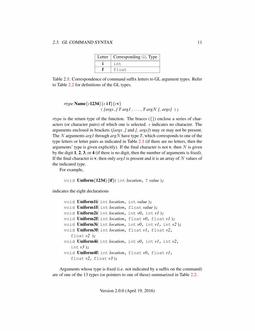
Letter Corresponding GL Typei intf float
Table 2.1: Correspondence of command suffix letters to GL argument types. Referto Table 2.2 for definitions of the GL types.
rtype Name{ε1234}{ε i f}{εv}( [args ,] T arg1 , . . . , T argN [, args] );
rtype is the return type of the function. The braces ({}) enclose a series of char-acters (or character pairs) of which one is selected. ε indicates no character. Thearguments enclosed in brackets ([args ,] and [, args]) may or may not be present.TheN arguments arg1 through argN have type T, which corresponds to one of thetype letters or letter pairs as indicated in Table 2.1 (if there are no letters, then thearguments’ type is given explicitly). If the final character is not v, then N is givenby the digit 1, 2, 3, or 4 (if there is no digit, then the number of arguments is fixed).If the final character is v, then only arg1 is present and it is an array of N values ofthe indicated type.
For example,
void Uniform{1234}{if}( int location, T value );
indicates the eight declarations
void Uniform1i( int location, int value );void Uniform1f( int location, float value );void Uniform2i( int location, int v0, int v1 );void Uniform2f( int location, float v0, float v1 );void Uniform3i( int location, int v0, int v1, int v2 );void Uniform3f( int location, float v1, float v2,
float v2 );void Uniform4i( int location, int v0, int v1, int v2,
int v3 );void Uniform4f( int location, float v0, float v1,
float v2, float v3 );
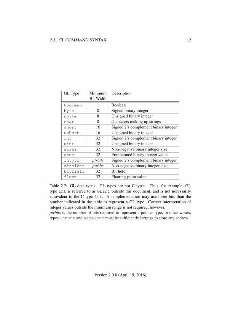
Arguments whose type is fixed (i.e. not indicated by a suffix on the command)are of one of the 13 types (or pointers to one of these) summarized in Table 2.2.
Version 2.0.0 (April 19, 2016)
2.3. GL COMMAND SYNTAX 12
GL Type Minimum DescriptionBit Width
boolean 1 Booleanbyte 8 Signed binary integerubyte 8 Unsigned binary integerchar 8 characters making up stringsshort 16 Signed 2’s complement binary integerushort 16 Unsigned binary integerint 32 Signed 2’s complement binary integeruint 32 Unsigned binary integersizei 32 Non-negative binary integer sizeenum 32 Enumerated binary integer valueintptr ptrbits Signed 2’s complement binary integersizeiptr ptrbits Non-negative binary integer sizebitfield 32 Bit fieldfloat 32 Floating-point value
Table 2.2: GL data types. GL types are not C types. Thus, for example, GLtype int is referred to as GLint outside this document, and is not necessarilyequivalent to the C type int. An implementation may use more bits than thenumber indicated in the table to represent a GL type. Correct interpretation ofinteger values outside the minimum range is not required, however.ptrbits is the number of bits required to represent a pointer type; in other words,types intptr and sizeiptr must be sufficiently large as to store any address.
Version 2.0.0 (April 19, 2016)
2.4. BASIC GL OPERATION 13
Per-VertexOperations
PrimitiveAssembly
Rasterization Per-FragmentOperations
Framebuffer
PixelOperations
TextureMemory
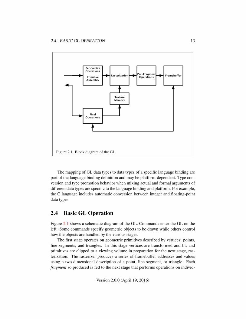
Figure 2.1. Block diagram of the GL.
The mapping of GL data types to data types of a specific language binding arepart of the language binding definition and may be platform-dependent. Type con-version and type promotion behavior when mixing actual and formal arguments ofdifferent data types are specific to the language binding and platform. For example,the C language includes automatic conversion between integer and floating-pointdata types.
2.4 Basic GL Operation
Figure 2.1 shows a schematic diagram of the GL. Commands enter the GL on theleft. Some commands specify geometric objects to be drawn while others controlhow the objects are handled by the various stages.
The first stage operates on geometric primitives described by vertices: points,line segments, and triangles. In this stage vertices are transformed and lit, andprimitives are clipped to a viewing volume in preparation for the next stage, ras-terization. The rasterizer produces a series of framebuffer addresses and valuesusing a two-dimensional description of a point, line segment, or triangle. Eachfragment so produced is fed to the next stage that performs operations on individ-
Version 2.0.0 (April 19, 2016)
2.5. GL ERRORS 14
ual fragments before they finally alter the framebuffer. These operations includeconditional updates into the framebuffer based on incoming and previously storeddepth values (to effect depth buffering), blending of incoming fragment colors withstored colors, and other operations on fragment values, such as masking (see chap-ter 4).
Values may also be read back from the framebuffer. These transfers may in-clude some type of decoding or encoding.
This ordering is meant only as a tool for describing the GL, not as a strict ruleof how the GL is implemented, and we present it only as a means to organize thevarious operations of the GL.
2.5 GL Errors
The GL detects only a subset of those conditions that could be considered errors.This is because in many cases error checking would adversely impact the perfor-mance of an error-free program.
From a safety critical point of view there are two types of error condition thatcan occur; deterministic or non-deterministic. It is advised for non-deterministicerrors, those that leave the run-time in an unknown state or unstable condition, tonot continue working with the current runtime instance and abort.
The command
enum GetError( void );
is used to obtain error information. Each detectable error is assigned a numericcode. When an error is detected, a flag is set and the code is recorded. Furthererrors, if they occur, do not affect this recorded code. When GetError is called,the code is returned and the flag is cleared, so that a further error will again recordits code. If a call to GetError returns NO_ERROR, then there has been no detectableerror since the last call to GetError (or since the GL was initialized).
To allow for distributed implementations, there may be several flag-code pairs.In this case, after a call to GetError returns a value other than NO_ERROR eachsubsequent call returns the non-zero code of a distinct flag-code pair (in unspecifiedorder), until all non-NO_ERROR codes have been returned. When there are no morenon-NO_ERROR error codes, all flags are reset. This scheme requires some positivenumber of pairs of a flag bit and an integer. The initial state of all flags is clearedand the initial value of all codes is NO_ERROR.
Table 2.3 summarizes GL errors. Currently, when an error flag is set, the com-mand generating the error is ignored so that it has no effect on GL state or frame-buffer contents. If the generating command returns a value, it returns zero. If
Version 2.0.0 (April 19, 2016)
2.6. GRAPHICS RESET RECOVERY 15
the generating command modifies values through a pointer argument, no changeis made to these values. These error semantics apply only to GL errors, includingOUT_OF_MEMORY, but not to system errors such as memory access errors. Exten-sions may change behavior that would otherwise generate errors in an unextendedGL implementation.
Several error generation conditions are implicit in the description of every GLcommand:
• If a command that requires an enumerated value is passed a symbolic con-stant that is not one of those specified as allowable for that command, the er-ror INVALID_ENUM error is generated. This is the case even if the argumentis a pointer to a symbolic constant, if the value pointed to is not allowablefor the given command.
• If a negative number is provided where an argument of type sizei is spec-ified, the error INVALID_VALUE is generated.
• If memory is exhausted as a side effect of the execution of a command, theerror OUT_OF_MEMORY may be generated.
• If the GL context has been reset as a result of a previous GL command, or ifthe context is reset as a side effect of execution of a command, a CONTEXT_-LOST error is generated.
Otherwise, errors are generated only for conditions that are explicitly described inthis specification.
2.6 Graphics Reset Recovery
Certain events can result in a reset of the GL context. After such an event, it isreferred to as a lost context and is unusable for almost all purposes. Recovery re-quires creating a new context and recreating all relevant state from the lost context.The current status of the graphics reset state is returned by
enum GetGraphicsResetStatus( void );
The value returned indicates if the GL context has been in a reset state at anypoint since the last call to GetGraphicsResetStatus:
• NO_ERROR indicates that the GL context has not been in a reset state sincethe last call
Version 2.0.0 (April 19, 2016)

2.6. GRAPHICS RESET RECOVERY 16
• GUILTY_CONTEXT_RESET indicates that a reset has been detected that isattributable to the current GL context
• INNOCENT_CONTEXT_RESET indicates a reset has been detected that is notattributable to the current GL context
• UNKNOWN_CONTEXT_RESET indicates a detected graphics reset whose causeis unknown
If a reset status other than NO_ERROR is returned and subsequent calls returnNO_ERROR, the context reset was encountered and completed. If a reset status isrepeatedly returned, the context may be in the process of resetting.
Reset notification behavior is determined at context creation time, andmay be queried by calling GetIntegerv with the symbolic constant RESET_-
NOTIFICATION_STRATEGY.If the reset notification behavior is NO_RESET_NOTIFICATION, then the im-
plementation will never deliver notification of reset events, and GetGraphicsRe-setStatus will always return NO_ERROR 2.
If the behavior is LOSE_CONTEXT_ON_RESET, a graphics reset will result ina lost context and require creating a new context as described above. In this caseGetGraphicsResetStatus will return an appropriate value from those describedabove.
If a graphics reset notification occurs in a context, a notification must also occurin all other contexts which share objects with that context 3.
After a graphics reset has occurred on a context, subsequent GL commandson that context (or any context which shares with that context) will generate aCONTEXT_LOST error. Such commands will not have side effects (in particular,they will not modify memory passed by pointer for query results), and may notblock indefinitely or cause termination of the application. Exceptions to this be-havior include:
• GetError and GetGraphicsResetStatus behave normally following agraphics reset, so that the application can determine a reset has occurred,and when it is safe to destroy and recreate the context
• Any commands which might cause a polling application to block indefinitelywill generate a CONTEXT_LOST error, but will also return a value indicatingcompletion to the application.
2 In this case it is recommended that implementations should not allow loss of context state nomatter what events occur. However, this is only a recommendation, and cannot be relied upon byapplications.
3 The values returned by GetGraphicsResetStatus in the different contexts may differ.
Version 2.0.0 (April 19, 2016)
2.7. PRIMITIVES AND VERTICES 17
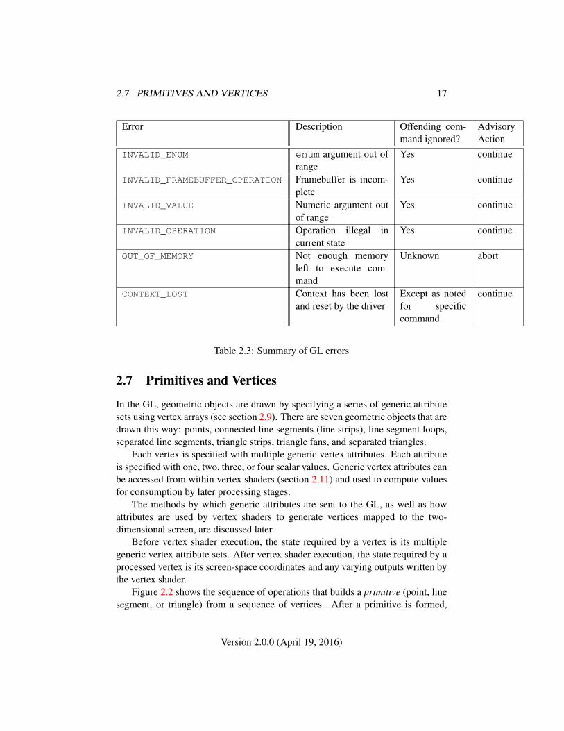
Error Description Offending com-mand ignored?
AdvisoryAction
INVALID_ENUM enum argument out ofrange
Yes continue
INVALID_FRAMEBUFFER_OPERATION Framebuffer is incom-plete
Yes continue
INVALID_VALUE Numeric argument outof range
Yes continue
INVALID_OPERATION Operation illegal incurrent state
Yes continue
OUT_OF_MEMORY Not enough memoryleft to execute com-mand
Unknown abort
CONTEXT_LOST Context has been lostand reset by the driver
Except as notedfor specificcommand
continue
Table 2.3: Summary of GL errors
2.7 Primitives and Vertices
In the GL, geometric objects are drawn by specifying a series of generic attributesets using vertex arrays (see section 2.9). There are seven geometric objects that aredrawn this way: points, connected line segments (line strips), line segment loops,separated line segments, triangle strips, triangle fans, and separated triangles.
Each vertex is specified with multiple generic vertex attributes. Each attributeis specified with one, two, three, or four scalar values. Generic vertex attributes canbe accessed from within vertex shaders (section 2.11) and used to compute valuesfor consumption by later processing stages.
The methods by which generic attributes are sent to the GL, as well as howattributes are used by vertex shaders to generate vertices mapped to the two-dimensional screen, are discussed later.
Before vertex shader execution, the state required by a vertex is its multiplegeneric vertex attribute sets. After vertex shader execution, the state required by aprocessed vertex is its screen-space coordinates and any varying outputs written bythe vertex shader.
Figure 2.2 shows the sequence of operations that builds a primitive (point, linesegment, or triangle) from a sequence of vertices. After a primitive is formed,
Version 2.0.0 (April 19, 2016)

2.7. PRIMITIVES AND VERTICES 18
Point,Line Segment, or
Triangle(Primitive)Assembly
Point culling,Line Segmentor Triangle
clipping
RasterizationShadedVertices
Coordinates
VaryingOutputs
Primitive type(from DrawArrays or
DrawRangeElements mode)
VertexShader
Execution
GenericVertex
Attributes
Figure 2.2. Vertex processing and primitive assembly.
Version 2.0.0 (April 19, 2016)

2.7. PRIMITIVES AND VERTICES 19
it is clipped to a viewing volume. This may alter the primitive by altering vertexcoordinates and varying outputs. In the case of line and triangle primitives, clippingmay insert new vertices into the primitive. The vertices defining a primitive to berasterized have varying outputs associated with them.
2.7.1 Primitive Types
A sequence of vertices is passed to the GL using the commands DrawArrays orDrawRangeElements (see section 2.9). There is no limit to the number of verticesthat may be specified, other than the size of the vertex arrays.
The mode parameter of these commands determines the type of primitives tobe drawn using these coordinate sets. The types, and the corresponding modeparameters, are:
Points. A series of individual points may be specified with mode POINTS.Each vertex defines a separate point.
Line Strips. A series of one or more connected line segments may be specifiedwith mode LINE_STRIP. At least two vertices must be provided. In this case, thefirst vertex specifies the first segment’s start point while the second vertex specifiesthe first segment’s endpoint and the second segment’s start point. In general, theith vertex (for i > 1) specifies the beginning of the ith segment and the end of thei − 1st. The last vertex specifies the end of the last segment. If only one vertex isspecified, then no primitive is generated.
The required state consists of the processed vertex produced from the precedingvertex that was passed (so that a line segment can be generated from it to the currentvertex), and a boolean flag indicating if the current vertex is the first vertex.
Line Loops. Line loops may be specified with mode LINE_LOOP. Loops arethe same as line strips except that a final segment is added from the final specifiedvertex to the first vertex.
The required state consists of the processed first vertex, in addition to the staterequired for line strips.
Separate Lines. Individual line segments, each specified by a pair of vertices,may be specified with mode LINES. The first two vertices passed define the firstsegment, with subsequent pairs of vertices each defining one more segment. If thenumber of specified vertices is odd, then the last one is ignored. The required stateis the same as for line strips but it is used differently: a processed vertex holdingthe first endpoint of the current segment, and a boolean flag indicating whether thecurrent vertex is odd or even (a segment start or end).
Triangle strips. A triangle strip is a series of triangles connected along sharededges, specified by giving a series of defining vertices with mode TRIANGLE_-
STRIP. In this case, the first three vertices define the first triangle (and their order
Version 2.0.0 (April 19, 2016)
2.7. PRIMITIVES AND VERTICES 20
(a) (b) (c)
1
2
3
4
5 1
23
4
51
2
3
4
5
6
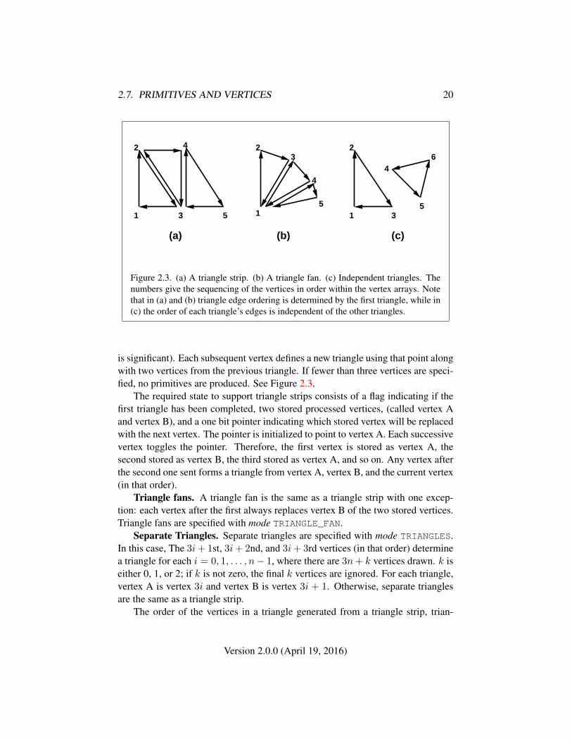
Figure 2.3. (a) A triangle strip. (b) A triangle fan. (c) Independent triangles. Thenumbers give the sequencing of the vertices in order within the vertex arrays. Notethat in (a) and (b) triangle edge ordering is determined by the first triangle, while in(c) the order of each triangle’s edges is independent of the other triangles.
is significant). Each subsequent vertex defines a new triangle using that point alongwith two vertices from the previous triangle. If fewer than three vertices are speci-fied, no primitives are produced. See Figure 2.3.
The required state to support triangle strips consists of a flag indicating if thefirst triangle has been completed, two stored processed vertices, (called vertex Aand vertex B), and a one bit pointer indicating which stored vertex will be replacedwith the next vertex. The pointer is initialized to point to vertex A. Each successivevertex toggles the pointer. Therefore, the first vertex is stored as vertex A, thesecond stored as vertex B, the third stored as vertex A, and so on. Any vertex afterthe second one sent forms a triangle from vertex A, vertex B, and the current vertex(in that order).
Triangle fans. A triangle fan is the same as a triangle strip with one excep-tion: each vertex after the first always replaces vertex B of the two stored vertices.Triangle fans are specified with mode TRIANGLE_FAN.
Separate Triangles. Separate triangles are specified with mode TRIANGLES.In this case, The 3i+ 1st, 3i+ 2nd, and 3i+ 3rd vertices (in that order) determinea triangle for each i = 0, 1, . . . , n− 1, where there are 3n+ k vertices drawn. k iseither 0, 1, or 2; if k is not zero, the final k vertices are ignored. For each triangle,vertex A is vertex 3i and vertex B is vertex 3i + 1. Otherwise, separate trianglesare the same as a triangle strip.
The order of the vertices in a triangle generated from a triangle strip, trian-
Version 2.0.0 (April 19, 2016)
2.8. CURRENT VERTEX STATE 21
gle fan, or separate triangles is significant in polygon rasterization and fragmentshading (see sections 3.5.1 and 3.8.2).
2.8 Current Vertex State
Vertex shaders (see section 2.11) access an array of 4-component generic vertexattributes. The first slot of this array is numbered 0, and the size of the array isspecified by the implementation-dependent constant MAX_VERTEX_ATTRIBS.
Current generic attribute values define generic attributes for a vertex when avertex array defining that data is not enabled, as described in section 2.9. A currentvalue may be changed at any time by issuing one of the commands
void VertexAttrib{1234}{f}( uint index, T values );void VertexAttrib{1234}{f}v( uint index, T values );
to load the given value(s) into the current generic attribute for slot index, whosecomponents are named x, y, z, and w. The VertexAttrib1* family of commandssets the x coordinate to the provided single argument while setting y and z to 0 andw to 1. Similarly, VertexAttrib2* commands set x and y to the specified values,z to 0 and w to 1; VertexAttrib3* commands set x, y, and z, with w set to 1, andVertexAttrib4* commands set all four coordinates. The error INVALID_VALUE isgenerated if index is greater than or equal to MAX_VERTEX_ATTRIBS.
The VertexAttrib* commands can also be used to load attributes declared as a2×2, 3×3 or 4×4 matrix in a vertex shader. Each column of a matrix takes up onegeneric 4-component attribute slot out of the MAX_VERTEX_ATTRIBS availableslots. Matrices are loaded into these slots in column major order. Matrix columnsneed to be loaded in increasing slot numbers.
The state required to support vertex specification consists of MAX_VERTEX_-ATTRIBS four-component floating-point vectors to store generic vertex attributes.The initial values for all generic vertex attributes are (0, 0, 0, 1).
2.9 Vertex Arrays
Vertex data is placed into arrays stored in the client’s address space (describedhere) or in the server’s address space (described in section 2.10). Blocks of data inthese arrays may then be used to specify multiple geometric primitives through theexecution of a single GL command. The client may specify up to MAX_VERTEX_-
ATTRIBS arrays specifying one or more generic vertex attributes. The command
Version 2.0.0 (April 19, 2016)
2.9. VERTEX ARRAYS 22
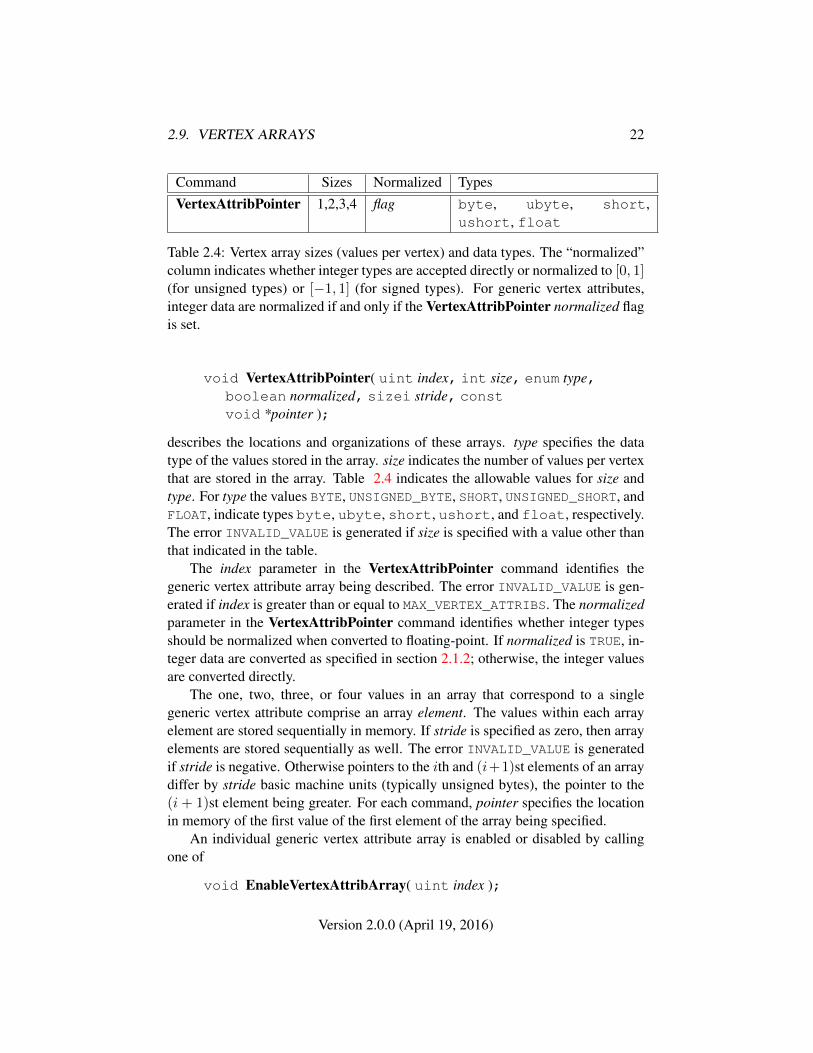
Command Sizes Normalized TypesVertexAttribPointer 1,2,3,4 flag byte, ubyte, short,
ushort, float
Table 2.4: Vertex array sizes (values per vertex) and data types. The “normalized”column indicates whether integer types are accepted directly or normalized to [0, 1](for unsigned types) or [−1, 1] (for signed types). For generic vertex attributes,integer data are normalized if and only if the VertexAttribPointer normalized flagis set.
void VertexAttribPointer( uint index, int size, enum type,boolean normalized, sizei stride, constvoid *pointer );
describes the locations and organizations of these arrays. type specifies the datatype of the values stored in the array. size indicates the number of values per vertexthat are stored in the array. Table 2.4 indicates the allowable values for size andtype. For type the values BYTE, UNSIGNED_BYTE, SHORT, UNSIGNED_SHORT, andFLOAT, indicate types byte, ubyte, short, ushort, and float, respectively.The error INVALID_VALUE is generated if size is specified with a value other thanthat indicated in the table.
The index parameter in the VertexAttribPointer command identifies thegeneric vertex attribute array being described. The error INVALID_VALUE is gen-erated if index is greater than or equal to MAX_VERTEX_ATTRIBS. The normalizedparameter in the VertexAttribPointer command identifies whether integer typesshould be normalized when converted to floating-point. If normalized is TRUE, in-teger data are converted as specified in section 2.1.2; otherwise, the integer valuesare converted directly.
The one, two, three, or four values in an array that correspond to a singlegeneric vertex attribute comprise an array element. The values within each arrayelement are stored sequentially in memory. If stride is specified as zero, then arrayelements are stored sequentially as well. The error INVALID_VALUE is generatedif stride is negative. Otherwise pointers to the ith and (i+1)st elements of an arraydiffer by stride basic machine units (typically unsigned bytes), the pointer to the(i + 1)st element being greater. For each command, pointer specifies the locationin memory of the first value of the first element of the array being specified.
An individual generic vertex attribute array is enabled or disabled by callingone of
void EnableVertexAttribArray( uint index );
Version 2.0.0 (April 19, 2016)
2.9. VERTEX ARRAYS 23
void DisableVertexAttribArray( uint index );
where index identifies the generic vertex attribute array to enable or disable. Theerror INVALID_VALUE is generated if index is greater than or equal to MAX_-
VERTEX_ATTRIBS.
Transferring Array Elements
When an array element i is transferred to the GL by the DrawArrays orDrawRangeElements commands, each generic attribute is expanded to four com-ponents. If size is one then the x component of the attribute is specified by thearray; the y, z, and w components are implicitly set to zero, zero, and one, respec-tively. If size is two then the x and y components of the attribute are specified bythe array; the z, and w components are implicitly set to zero, and one, respectively.If size is three then x, y, and z are specified, and w is implicitly set to one. If sizeis four then all components are specified.
The command
void DrawArrays( enum mode, int first, sizei count );
constructs a sequence of geometric primitives by successively transferring ele-ments first through first + count − 1 of each enabled array to the GL. modespecifies what kind of primitives are constructed, as defined in section 2.7.1. Ifan array corresponding to a generic attribute required by a vertex shader is not en-abled, then the corresponding element is taken from the current generic attributestate (see section 2.8).
Specifying first < 0 results in generating the error INVALID_VALUE.The command
void DrawRangeElements( enum mode, uint start, uint end,sizei count, enum type, const void *indices );
constructs a sequence of geometric primitives by successively transferring thecount elements whose indices are stored in indices to the GL. The ith elementtransferred by DrawRangeElements will be taken from element indices[i] ofeach enabled array. type must be UNSIGNED_SHORT, indicating that the valuesin indices are indices of GL type ushort. mode specifies what kind of primitivesare constructed; it accepts the same values as the mode parameter of DrawArrays.If an array corresponding to a generic attribute required by a vertex shader is notenabled, then the corresponding element is taken from the current generic attributestate (see section 2.8).
Version 2.0.0 (April 19, 2016)
2.10. BUFFER OBJECTS 24
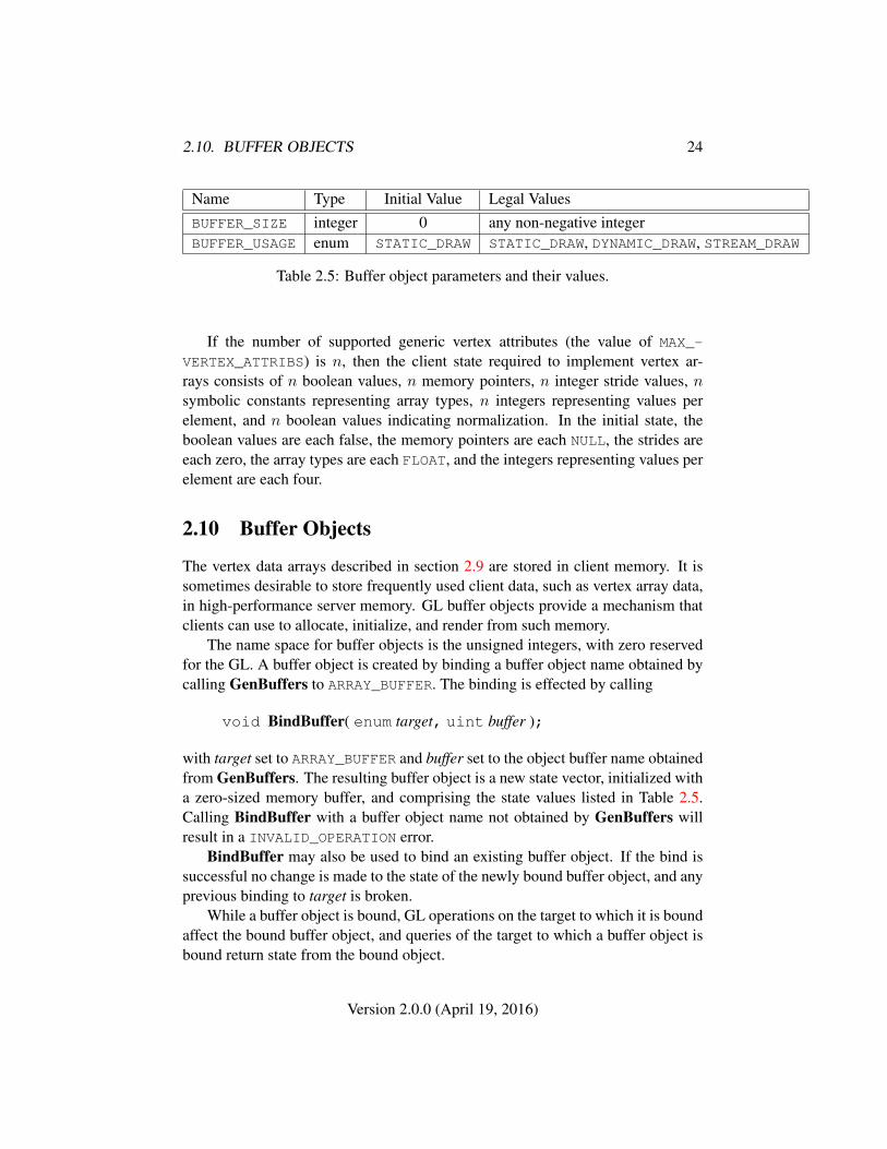
Name Type Initial Value Legal ValuesBUFFER_SIZE integer 0 any non-negative integerBUFFER_USAGE enum STATIC_DRAW STATIC_DRAW, DYNAMIC_DRAW, STREAM_DRAW
Table 2.5: Buffer object parameters and their values.
If the number of supported generic vertex attributes (the value of MAX_-
VERTEX_ATTRIBS) is n, then the client state required to implement vertex ar-rays consists of n boolean values, n memory pointers, n integer stride values, nsymbolic constants representing array types, n integers representing values perelement, and n boolean values indicating normalization. In the initial state, theboolean values are each false, the memory pointers are each NULL, the strides areeach zero, the array types are each FLOAT, and the integers representing values perelement are each four.
2.10 Buffer Objects
The vertex data arrays described in section 2.9 are stored in client memory. It issometimes desirable to store frequently used client data, such as vertex array data,in high-performance server memory. GL buffer objects provide a mechanism thatclients can use to allocate, initialize, and render from such memory.
The name space for buffer objects is the unsigned integers, with zero reservedfor the GL. A buffer object is created by binding a buffer object name obtained bycalling GenBuffers to ARRAY_BUFFER. The binding is effected by calling
void BindBuffer( enum target, uint buffer );
with target set to ARRAY_BUFFER and buffer set to the object buffer name obtainedfrom GenBuffers. The resulting buffer object is a new state vector, initialized witha zero-sized memory buffer, and comprising the state values listed in Table 2.5.Calling BindBuffer with a buffer object name not obtained by GenBuffers willresult in a INVALID_OPERATION error.
BindBuffer may also be used to bind an existing buffer object. If the bind issuccessful no change is made to the state of the newly bound buffer object, and anyprevious binding to target is broken.
While a buffer object is bound, GL operations on the target to which it is boundaffect the bound buffer object, and queries of the target to which a buffer object isbound return state from the bound object.
Version 2.0.0 (April 19, 2016)
2.10. BUFFER OBJECTS 25
In the initial state the reserved name zero is bound to ARRAY_BUFFER. Thereis no buffer object corresponding to the name zero, so client attempts to modifyor query buffer object state for the target ARRAY_BUFFER while zero is bound willgenerate GL errors.
Buffer objects cannot be deleted.The command
void GenBuffers( sizei n, uint *buffers );
returns n previously unused buffer object names in buffers. These names aremarked as used, for the purposes of GenBuffers only, but they acquire buffer stateonly when they are first bound, just as if they were unused.
While a buffer object is bound, any GL operations on that object affect anyother bindings of that object.
The data store of a buffer object is created and initialized by calling
void BufferData( enum target, sizeiptr size, constvoid *data, enum usage );
with target set to ARRAY_BUFFER, size set to the size of the data store in basicmachine units, and data pointing to the source data in client memory. If data isnon-null, then the source data is copied to the buffer object’s data store. If data isnull, then the contents of the buffer object’s data store are uninitialized.
usage is specified as one of three enumerated values, indicating the expectedapplication usage pattern of the data store. The values are:
STATIC_DRAW The data store contents will be specified once by the application,and used many times as the source for GL drawing commands.
DYNAMIC_DRAW The data store contents will be respecified repeatedly by the ap-plication, and used many times as the source for GL drawing commands.
STREAM_DRAW The data store contents will be specified once by the application,and used at most a few times as the source of a GL drawing command.
usage is provided as a performance hint only. The specified usage value doesnot constrain the actual usage pattern of the data store.
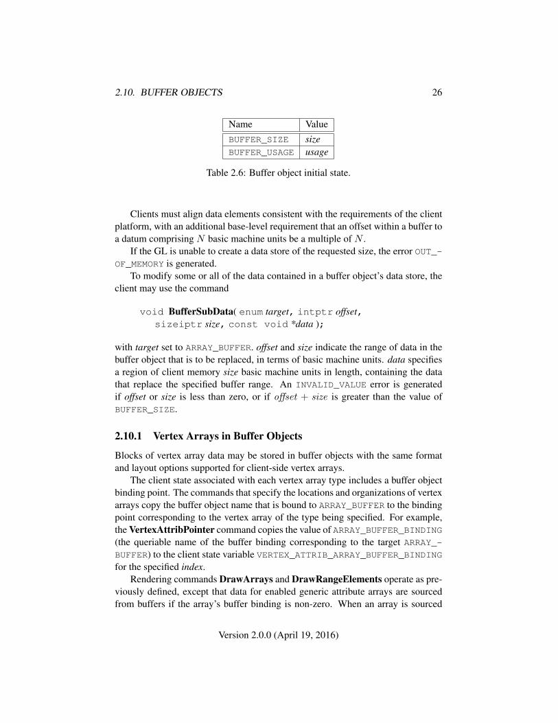
BufferData sets the values of the buffer object’s state variables as shown intable 2.6. Once established these values are considered immutable and cannotbe changed. Attempting to change these state variables of a buffer object onceestablished will result in an INVALID_OPERATION error.
Version 2.0.0 (April 19, 2016)
2.10. BUFFER OBJECTS 26
Name ValueBUFFER_SIZE sizeBUFFER_USAGE usage
Table 2.6: Buffer object initial state.
Clients must align data elements consistent with the requirements of the clientplatform, with an additional base-level requirement that an offset within a buffer toa datum comprising N basic machine units be a multiple of N .
If the GL is unable to create a data store of the requested size, the error OUT_-OF_MEMORY is generated.
To modify some or all of the data contained in a buffer object’s data store, theclient may use the command
void BufferSubData( enum target, intptr offset,sizeiptr size, const void *data );
with target set to ARRAY_BUFFER. offset and size indicate the range of data in thebuffer object that is to be replaced, in terms of basic machine units. data specifiesa region of client memory size basic machine units in length, containing the datathat replace the specified buffer range. An INVALID_VALUE error is generatedif offset or size is less than zero, or if offset + size is greater than the value ofBUFFER_SIZE.
2.10.1 Vertex Arrays in Buffer Objects
Blocks of vertex array data may be stored in buffer objects with the same formatand layout options supported for client-side vertex arrays.
The client state associated with each vertex array type includes a buffer objectbinding point. The commands that specify the locations and organizations of vertexarrays copy the buffer object name that is bound to ARRAY_BUFFER to the bindingpoint corresponding to the vertex array of the type being specified. For example,the VertexAttribPointer command copies the value of ARRAY_BUFFER_BINDING(the queriable name of the buffer binding corresponding to the target ARRAY_-BUFFER) to the client state variable VERTEX_ATTRIB_ARRAY_BUFFER_BINDINGfor the specified index.
Rendering commands DrawArrays and DrawRangeElements operate as pre-viously defined, except that data for enabled generic attribute arrays are sourcedfrom buffers if the array’s buffer binding is non-zero. When an array is sourced
Version 2.0.0 (April 19, 2016)
2.11. VERTEX SHADERS 27
from a buffer object, the pointer value of that array is used to compute an offset, inbasic machine units, into the data store of the buffer object. This offset is computedby subtracting a null pointer from the pointer value, where both pointers are treatedas pointers to basic machine units4.
It is acceptable for generic vertex attribute arrays to be sourced from any com-bination of client memory and various buffer objects during a single renderingoperation.
2.10.2 Array Indices in Buffer Objects
Blocks of array indices may be stored in buffer objects with the same format op-tions that are supported for client-side index arrays. Initially zero is bound toELEMENT_ARRAY_BUFFER, indicating that DrawRangeElements is to source itsindices from arrays passed as the indices parameters.
A buffer object is bound to ELEMENT_ARRAY_BUFFER by calling BindBufferwith target set to ELEMENT_ARRAY_BUFFER, and buffer set to the name of thebuffer object. If no corresponding buffer object exists, one is initialized as definedin section 2.10.
The commands BufferData and BufferSubData may be used with target setto ELEMENT_ARRAY_BUFFER. In such event, these commands operate in the samefashion as described in section 2.10, but on the buffer currently bound to theELEMENT_ARRAY_BUFFER target.
While a non-zero buffer object name is bound to ELEMENT_ARRAY_BUFFER,DrawRangeElements sources its indices from that buffer object, using elementsof the indices parameter as offsets into the buffer object in the same fashion asdescribed in section 2.10.1.
Buffer objects created by binding an unused name to ARRAY_BUFFER and toELEMENT_ARRAY_BUFFER are formally equivalent, but the GL may make differentchoices about storage implementation based on the initial binding. In some casesperformance will be optimized by storing indices and array data in separate bufferobjects, and by creating those buffer objects with the corresponding binding points.
2.11 Vertex Shaders
Vertices specified with DrawArrays or DrawRangeElements are processed bythe vertex shader. Each vertex attribute consumed by the vertex shader (see sec-
4 To resume using client-side vertex arrays after a buffer object has been bound, call Bind-Buffer(ARRAY_BUFFER,0) and then specify the client vertex array pointer using the appropriatecommand from section 2.9.
Version 2.0.0 (April 19, 2016)

2.11. VERTEX SHADERS 28
tion 2.11.2) is set to the corresponding generic vertex attribute value from the arrayelement being processed, or from the corresponding current generic attribute if novertex array is bound for that attribute.
After shader execution, processed vertices are passed on to primitive assembly(see section 2.12).
A vertex shader contains source code for the operations that are meant to occuron each vertex that is processed. The language used for vertex shaders is describedin the OpenGL ES Shading Language Specification.
To use a vertex shader, shader source code is first compiled off-line intoa shader object. Shader objects are linked off-line into a program binary ob-ject which generates executable code from the specified compiled shader objects.When a linked program binary object is used as the current program object, theexecutable code for the vertex shaders it contains is used to process vertices
In addition to vertex shaders, fragment shaders are also compiled off-line intoshader objects. Fragment shaders affect the processing of fragments during raster-ization, and are described in section 3.8.
A single program binary object must contain both a vertex and a fragmentshader.
2.11.1 Program Objects
The shader objects that are to be used by the programmable stages of the GL arecollected together to form a program object. The programs that are executed bythese programmable stages are called executables. All information necessary fordefining an executable is encapsulated in a program object. A program object iscreated with the command
uint CreateProgram( void );
Program objects are empty when they are created. A non-zero name that can beused to reference the program object is returned. If an error occurs, 0 will bereturned. Program objects cannot be deleted and once a program binary object isloaded into program object, it cannot be replaced.
To load a pre-compiled program binary into a program object, use the com-mand
void ProgramBinary( uint program, enum binaryformat,const void *binary, sizei length );
This command will copy the pre-compiled program binary object of size lengthfrom binary into the program object program. Calling ProgramBinary with a
Version 2.0.0 (April 19, 2016)
2.11. VERTEX SHADERS 29
program that already has a program binary object will generate an INVALID_-
OPERATION error and the existing program binary object is not modified.The binary image will be decoded according to the extension specification
defining the specified binaryformat. OpenGL SC defines no specific binary for-mats, but does provide a mechanism to obtain token values for such formats pro-vided by extensions. The number of program binary formats supported can beobtained by querying the value of NUM_PROGRAM_BINARY_FORMATS. The listof specific binary formats supported can be obtained by querying the value ofPROGRAM_BINARY_FORMATS.
When a program object has a program binary object loaded, it can be made partof the current rendering state with the command
void UseProgram( uint program );
This command will install the executable code as part of current rendering state ifthe program object program contains a successfully loaded program binary. If Use-Program is called with program set to zero, then the current rendering state refersto an invalid program object, and no vertex or fragment shader executions due toany DrawArrays or DrawRangeElements commands are performed. However,this is not an error. If program does not contain a successfully loaded program bi-nary, the error INVALID_OPERATION is generated and the current rendering stateis not modified.
2.11.2 Shader Variables
A vertex shader can reference a number of variables as it executes. Vertex attributesare the per-vertex values specified in section 2.8. Uniforms are per-program vari-ables that are constant during program execution. Samplers are a special form ofuniform used for texturing (section 3.7). Varying variables hold the results of ver-tex shader execution that are used later in the pipeline. The following sectionsdescribe each of these variable types.
Vertex Attributes
Vertex shaders can define named attribute variables, which are bound to the genericvertex attributes that are set by VertexAttrib*. This is automatically assigned bythe GL when the program is linked.
When an attribute variable declared as a float, vec2, vec3 or vec4 is boundto a generic attribute index i, its value(s) are taken from the x, (x, y), (x, y, z), or(x, y, z, w) components, respectively, of the generic attribute i. When an attribute
Version 2.0.0 (April 19, 2016)
2.11. VERTEX SHADERS 30
variable is declared as a mat2, its matrix columns are taken from the (x, y) com-ponents of generic attributes i and i + 1. When an attribute variable is declaredas a mat3, its matrix columns are taken from the (x, y, z) components of genericattributes i through i + 2. When an attribute variable is declared as a mat4, itsmatrix columns are taken from the (x, y, z, w) components of generic attributes ithrough i+ 3.
A generic attribute variable is considered active if it is determined by the com-piler and linker that the attribute may be accessed when the shader is executed.Attribute variables that are declared in a vertex shader but never used are not con-sidered active. In cases where the compiler and linker cannot make a conclusivedetermination, an attribute will be considered active. A program object will fail tolink if the number of active vertex attributes exceeds MAX_VERTEX_ATTRIBS.
The bindings of attribute variable names to indices can be queried using thecommand
int GetAttribLocation( uint program, const char *name );
returns the generic attribute index that the attribute variable named name was boundto when the program object named program was linked. name must be a null-terminated string. If name is active and is an attribute matrix, GetAttribLocationreturns the index of the first column of that matrix. If program was not successfullyloaded, the error INVALID_OPERATION is generated. If name is not an activeattribute, or if an error occurs, -1 will be returned.
Uniform Variables
Shaders can declare named uniform variables, as described in the OpenGL ESShading Language Specification. Values for these uniforms are constant over aprimitive, and typically they are constant across many primitives. Uniforms areprogram object-specific state. They retain their values once loaded, and their valuesare restored whenever a program object is used. A uniform is considered active if itis determined by the compiler and linker that the uniform will actually be accessedwhen the code is executed. In cases where the compiler and linker cannot make aconclusive determination, the uniform will be considered active.
The amount of storage available for uniform variables accessed by a vertexshader is specified by the implementation-dependent constant MAX_VERTEX_-UNIFORM_VECTORS. This value represents the number of four-element floating-point, integer, or boolean vectors that can be held in uniform variable storage for avertex shader. A link error will be generated if an attempt is made to utilize morethan the space available for vertex shader uniform variables.
Version 2.0.0 (April 19, 2016)
2.11. VERTEX SHADERS 31
When a program is successfully loaded, all active uniforms belonging to theprogram object are initialized to zero (FALSE for booleans). A successful link willgenerate a location for each active uniform. The values of active uniforms can bechanged using this location and the appropriate Uniform* command (see below).
To find the location of an active uniform variable within a program object, usethe command
int GetUniformLocation( uint program, constchar *name );
This command will return the location of uniform variable name. name must be anull terminated string, without white space. The value -1 will be returned if namedoes not correspond to an active uniform variable name in program or if name startswith the reserved prefix "gl_". If program has not been successfully loaded, theerror INVALID_OPERATION is generated.
A valid name cannot be a structure, an array of structures, or any portion ofa single vector or a matrix. In order to identify a valid name, the "." (dot) and"[]" operators can be used in name to specify a member of a structure or elementof an array.
The first element of a uniform array is identified using the name of the uniformarray appended with "[0]". Except if the last part of the string name indicates auniform array, then the location of the first element of that array can be retrievedby either using the name of the uniform array, or the name of the uniform arrayappended with "[0]".
To load values into the uniform variables of the program object that is currentlyin use, use the commands
void Uniform{1234}{if}( int location, T value );void Uniform{1234}{if}v( int location, sizei count,
T value );void UniformMatrix{234}fv( int location, sizei count,
boolean transpose, const float *value );
The given values are loaded into the uniform variable location identified by loca-tion.
The Uniform*f{v} commands will load count sets of one to four floating-pointvalues into a uniform location defined as a float, a floating-point vector, an array offloats, or an array of floating-point vectors.
The Uniform*i{v} commands will load count sets of one to four integer val-ues into a uniform location defined as a sampler, an integer, an integer vector, an
Version 2.0.0 (April 19, 2016)
2.11. VERTEX SHADERS 32
array of samplers, an array of integers, or an array of integer vectors. Only theUniform1i{v} commands can be used to load sampler values (see below).
The UniformMatrix{234}fv commands will load count 2× 2, 3× 3, or 4× 4matrices (corresponding to 2, 3, or 4 in the command name) of floating-point valuesinto a uniform location defined as a matrix or an array of matrices. The matrix isspecified in column-major order. transpose must be FALSE.
When loading values for a uniform declared as a boolean, a boolean vector,an array of booleans, or an array of boolean vectors, both the Uniform*i{v} andUniform*f{v} set of commands can be used to load boolean values. Type conver-sion is done by the GL. The uniform is set to FALSE if the input value is 0 or 0.0f,and set to TRUE otherwise. The Uniform* command used must match the size ofthe uniform, as declared in the shader. For example, to load a uniform declaredas a bvec2, either Uniform2i{v} or Uniform2f{v} can be used. An INVALID_-
OPERATION error will be generated if an attempt is made to use a non-matchingUniform* command. In this example using Uniform1iv would generate an error.
For all other uniform types the Uniform* command used must match the sizeand type of the uniform, as declared in the shader. No type conversions aredone. For example, to load a uniform declared as a vec4, Uniform4f{v} mustbe used. To load a 3x3 matrix, UniformMatrix3fv must be used. An INVALID_-
OPERATION error will be generated if an attempt is made to use a non-matchingUniform* command. In this example, using Uniform4i{v} would generate anerror.
When loading N elements starting at an arbitrary position k in a uniform de-clared as an array, elements k through k + N − 1 in the array will be replacedwith the new values. Values for any array element that exceeds the highest arrayelement index used will be ignored by the GL.
If the value of location is -1, the Uniform* commands will silently ignore thedata passed in, and the current uniform values will not be changed.
If the transpose parameter to any of the UniformMatrix* commands isnot FALSE, an INVALID_VALUE error is generated, and no uniform values arechanged.
If any of the following conditions occur, an INVALID_OPERATION error isgenerated by the Uniform* commands, and no uniform values are changed:
• if the size indicated in the name of the Uniform* command used does notmatch the size of the uniform declared in the shader,
• if the uniform declared in the shader is not of type boolean and the typeindicated in the name of the Uniform* command used does not match thetype of the uniform,
Version 2.0.0 (April 19, 2016)
2.11. VERTEX SHADERS 33
• if count is greater than one, and the uniform declared in the shader is not anarray variable,
• if no variable with a location of location exists in the program object cur-rently in use and location is not -1, or
• if there is no program object currently in use.
Samplers
Samplers are special uniforms used in the OpenGL ES Shading Language toidentify the texture object used for each texture lookup. The value of a sam-pler indicates the texture image unit being accessed. Setting a sampler’s valueto i selects texture image unit number i. The values of i range from zero to theimplementation-dependent maximum supported number of texture image units.
The type of the sampler identifies the target on the texture image unit. Thetexture object bound to that texture image unit’s target is then used for the texturelookup. For example, a variable of type sampler2D selects target TEXTURE_2Don its texture image unit. Binding of texture objects to targets is done as usual withBindTexture. Selecting the texture image unit to bind to is done as usual withActiveTexture.
The location of a sampler needs to be queried with GetUniformLocation, justlike any uniform variable. Sampler values need to be set by calling Uniform1i{v}.Loading samplers with any of the other Uniform* entry points is not allowed andwill result in an INVALID_OPERATION error.
It is not allowed to have variables of different sampler types pointing to thesame texture image unit within a program object. This situation can only be de-tected at the next rendering command issued, and an INVALID_OPERATION errorwill then be generated.
Active samplers are samplers actually being used in a program object. The off-line linker determines if a sampler is active or not. The off-line linker will attemptto determine if the active samplers in the shader(s) contained in the program ob-ject exceed the maximum allowable limits. If it determines that the count of activesamplers exceeds the allowable limits, then the link fails (these limits can be dif-ferent for different types of shaders). Each active sampler variable counts againstthe limit, even if multiple samplers refer to the same texture image unit. If thiscannot be determined at link time, then it will be determined at the next renderingcommand issued, and an INVALID_OPERATION error will then be generated.
Version 2.0.0 (April 19, 2016)
2.11. VERTEX SHADERS 34
Varying Variables
A vertex shader may define one or more varying variables (see the OpenGL ESShading Language specification). These values are expected to be interpolatedacross the primitive being rendered. The OpenGL ES Shading Language specifi-cation defines a set of built-in varying variables for vertex shaders correspondingto values required for rasterization following vertex processing.
The number of interpolators available for processing varying variables is givenby the implementation-dependent constant MAX_VARYING_VECTORS. This valuerepresents the number of four-element floating-point vectors that can be interpo-lated; varying variables declared as matrices or arrays will consume multiple in-terpolators. When a program is linked, any varying variable written by a vertexshader, or read by a fragment shader, will count against this limit. The transformedvertex position (gl_Position) is not a varying variable and does not countagainst this limit. A program whose shaders access more than MAX_VARYING_-
VECTORS worth of varying variables may fail to link, unless device-dependent op-timizations are able to make the program fit within available hardware resources.
2.11.3 Shader Execution
If a successfully loaded program object that contains a vertex shader is made cur-rent by calling UseProgram, the executable version of the vertex shader is used toprocess incoming vertex values.
There are several special considerations for vertex shader execution describedin the following sections.
Texture Access
Vertex shaders have the ability to do a lookup into a texture map, if supported bythe GL implementation. The maximum number of texture image units available toa vertex shader is MAX_VERTEX_TEXTURE_IMAGE_UNITS; a maximum number ofzero indicates that the GL implemenation does not support texture accesses in ver-tex shaders. The maximum number of texture image units available to the fragmentstage of the GL is MAX_TEXTURE_IMAGE_UNITS. Both the vertex shader and frag-ment processing combined cannot use more than MAX_COMBINED_TEXTURE_-
IMAGE_UNITS texture image units. If both the vertex shader and the fragmentprocessing stage access the same texture image unit, then that counts as using twotexture image units against the MAX_COMBINED_TEXTURE_IMAGE_UNITS limit.
When a texture lookup is performed in a vertex shader, the filtered texture valueτ is computed in the manner described in sections 3.7.6 and 3.7.7, and converted to
Version 2.0.0 (April 19, 2016)
2.11. VERTEX SHADERS 35
a texture source color Cs according to table 3.9 (section 3.8.2). A four-componentvector (Rs, Gs, Bs, As) is returned to the vertex shader.
In a vertex shader, it is not possible to perform automatic level-of-detail calcu-lations using partial derivatives of the texture coordinates with respect to windowcoordinates as described in section 3.7.6. Hence, there is no automatic selection ofan image array level. Minification or magnification of a texture map is controlledby a level-of-detail value optionally passed as an argument in the texture lookupfunctions. If the texture lookup function supplies an explicit level-of-detail value l,then the pre-bias level-of-detail value λbase(x, y) = l (replacing equation 3.11). Ifthe texture lookup function does not supply an explicit level-of-detail value, thenλbase(x, y) = 0. The scale factor ρ(x, y) and its approximation function f(x, y)(see equation 3.12) are ignored.
Using a sampler in a vertex shader will return (R,G,B,A) = (0, 0, 0, 1) underthe same conditions as defined for fragment shaders under “Texture Access” insection 3.8.2.
Out-of-Bounds Robustness Behavior
GL commands operating on buffer objects will detect attempts to read from orwrite to a location in a bound buffer object at an offset less than zero, or greaterthan or equal to the buffers size. When such an attempt is detected, a GL erroris generated. Any command unable to generate a GL error, such as buffer objectaccesses from the active program, will not read or modify memory outside of thedata store of the buffer object and will not result in GL interruption or termination.
Out-of-bounds accesses will be bounded within the working memory of theactive program, cannot access memory owned by other GL contexts, and will notresult in abnormal program termination. Out-of-bounds access to local and globalvariables cannot read values from other program invocations.
Out-of-bounds accesses to arrays of resources, such as an array of textures, canonly access the data of bound resources. Reads from unbound resources returnzero and writes are discarded. It is not possible to access data owned by other GLcontexts unless context sharing is enabled.
Out-of-bounds buffer object reads may return any of the following values:
• Values from anywhere within the buffer object.
• Zero values, or (0,0,0,x) vectors for vector reads where x is a valid valuerepresented in the type of the vector components and may be any of
0, 1, or the maximum representable positive integer value, for signed orunsigned integer components
Version 2.0.0 (April 19, 2016)
2.11. VERTEX SHADERS 36
0.0 or 1.0, for floating-point components
However, indices within the element array that reference vertex data that liesoutside the enabled attribute’s vertex buffer object result in reading zero.
Applications that require defined behavior for out-of-bounds accesses shouldrange check all computed indices before dereferencing the array, vector or matrix.
2.11.4 Required State
The GL maintains state to indicate which program object names are in use. Ini-tially, no program objects exist, and no names are in use.The state required per program object consists of:
• An unsigned integer indicating the program object name.
• A boolean holding the status of the last load attempt, initially FALSE.
• A boolean holding the status of the last validation attempt, initially FALSE.
• An array of type char containing the information log, initially empty.
• An integer holding the length of the information log.
• An integer holding the number of active uniforms.
• For each active uniform, three integers, holding its location, size, and type,and an array of type char holding its name.
• An array of words that hold the values of each active uniform.
• An integer holding the number of active attributes.
• For each active attribute, three integers holding its location, size, and type,and an array of type char holding its name.
Additionally, one unsigned integer is required to hold the name of the current pro-gram object. Initially the current program object is invalid, as if UseProgram hadbeen called with program set to zero.
Version 2.0.0 (April 19, 2016)
2.12. PRIMITIVE ASSEMBLY AND POST-SHADER VERTEX PROCESSING37
2.12 Primitive Assembly and Post-Shader Vertex Process-ing
Following vertex processing, vertices are assembled into primitives according tothe mode argument of the drawing command (see sections 2.7.1 and 2.9). Thesteps of primitive assembly are described in the remaining sections of this chapterand include
• Perspective division on clip coordinates (section 2.13).
• Viewport mapping, including depth range scaling (section 2.13.1).
• Primitive clipping (section 2.14).
• Clipping varying outputs (section 2.14.1).
2.13 Coordinate Transformations
Vertex shader execution yields a vertex coordinate gl_Position which is as-sumed to be in clip coordinates. Perspective division is carried out on clip coordi-nates to yield normalized device coordinates, followed by a viewport transforma-tion to convert these coordinates into window coordinates (see figure 2.4).
Clip coordinates are four-dimensional homogeneous vectors consisting of x, y,z, and w coordinates (in that order). If a vertex’s clip coordinates are
xcyczcwc
then the vertex’s normalized device coordinates arexdyd
zd
=
xcwcyewczewc
.
2.13.1 Controlling the Viewport
The viewport transformation is determined by the viewport’s width and height inpixels, px and py, respectively, and its center (ox, oy) (also in pixels). The vertex’s
Version 2.0.0 (April 19, 2016)

2.13. COORDINATE TRANSFORMATIONS 38
ViewportTransformation
WindowCoordinatesClip Coordinates
PerspectiveDivision
NormalizedDevice Coordinates
Figure 2.4. Vertex transformation sequence.
window coordinates,
xwywzw
, are given by
xwywzw
=
px2 xd + oxpy2 yd + oy
f−n2 zd + n+f
2
.
The factor and offset applied to zd encoded by n and f are set using
void DepthRangef( float n, float f );
Each of n and f are clamped to lie within [0, 1], as are all arguments of type float.zw is taken to be represented in fixed-point with at least as many bits as there arein the depth buffer of the framebuffer, as described for framebuffer components insection 2.1.2.
Viewport transformation parameters are specified using
void Viewport( int x, int y, sizei w, sizei h );
where x and y give the x and y window coordinates of the viewport’s lower leftcorner and w and h give the viewport’s width and height, respectively. The viewport
Version 2.0.0 (April 19, 2016)
2.14. PRIMITIVE CLIPPING 39
parameters shown in the above equations are found from these values as ox = x+w2
and oy = y + h2 ; px = w, py = h.
Viewport width and height are clamped to implementation-dependent maxi-mums when specified. The maximum width and height may be found by issuingan appropriate Get command (see Chapter 6). The maximum viewport dimen-sions must be greater than or equal to the visible dimensions of the display beingrendered to. INVALID_VALUE is generated if either w or h is negative.
The state required to implement the viewport transformation is four integersand two clamped floating-point values. In the initial state, w and h are set to thewidth and height, respectively, of the window into which the GL is to do its ren-dering. If no default framebuffer is associated with the GL context (see chapter 4),then w and h are initially set to zero. ox and oy are set to w
2 and h2 , respectively. n
and f are set to 0.0 and 1.0, respectively.
2.14 Primitive Clipping
Primitives are clipped to the clip volume. In clip coordinates, the clip volume isdefined by
−wc ≤ xc ≤ wc
−wc ≤ yc ≤ wc
−wc ≤ zc ≤ wc.
If the primitive under consideration is a point, then clipping discards it if it liesoutside the near or far clip plane; otherwise it is passed unchanged.
If the primitive is a line segment, then clipping does nothing to it if it liesentirely inside the near and far clip planes, and discards it if it lies entirely outsidethese planes.
If part of the line segment lies between the near and far clip planes, and partlies outside, then the line segment is clipped against these planes and new vertexcoordinates are computed for one or both vertices.
This clipping produces a value, 0 ≤ t ≤ 1, for each clipped vertex. If thecoordinates of a clipped vertex are P and the original vertices’ coordinates are P1
and P2, then t is given by
P = tP1 + (1− t)P2.
If the primitive is a triangle, then it is passed if every one of its edges liesentirely inside the clip volume and either clipped or discarded otherwise. Clip-ping may cause triangle edges to be clipped, but because connectivity must bemaintained, these clipped edges are connected by new edges that lie along the clip
Version 2.0.0 (April 19, 2016)

2.14. PRIMITIVE CLIPPING 40
volume’s boundary. Thus, clipping may require the introduction of new verticesinto a triangle, creating a more general polygon.
If it happens that a triangle intersects an edge of the clip volume’s boundary,then the clipped triangle must include a point on this boundary edge.
A line segment or triangle whose vertices havewc values of differing signs maygenerate multiple connected components after clipping. GL implementations arenot required to handle this situation. That is, only the portion of the primitive thatlies in the region of wc > 0 need be produced by clipping.
2.14.1 Clipping Varying Outputs
Next, vertex shader varying variables are clipped. The varying values associatedwith a vertex that lies within the clip volume are unaffected by clipping. If a prim-itive is clipped, however, the varying values assigned to vertices produced by clip-ping are clipped values.
Let the varying values assigned to the two vertices P1 and P2 of an unclippededge be c1 and c2. The value of t (section 2.14) for a clipped point P is used toobtain the value associated with P as5
c = tc1 + (1− t)c2.
(Multiplying a varying value by a scalar means multiplying each of x, y, z, and wby the scalar.)
Polygon clipping may create a clipped vertex along an edge of the clip volume’sboundary. This situation is handled by noting that polygon clipping proceeds byclipping against one plane of the clip volume’s boundary at a time. Varying valueclipping is done in the same way, so that clipped points always occur at the intersec-tion of polygon edges (possibly already clipped) with the clip volume’s boundary.
5 Since this computation is performed in clip space before division by wc, clipped varying valuesare perspective-correct.
Version 2.0.0 (April 19, 2016)
Chapter 3
Rasterization
Rasterization is the process by which a primitive is converted to a two-dimensionalimage. Each point of this image contains such information as color and depth.Thus, rasterizing a primitive consists of two parts. The first is to determine whichsquares of an integer grid in window coordinates are occupied by the primitive.The second is assigning a color and a depth value to each such square. The resultsof this process are passed on to the next stage of the GL (per-fragment operations),which uses the information to update the appropriate locations in the framebuffer.Figure 3.1 diagrams the rasterization process. The color values assigned to a frag-ment are determined by a fragment shader (as defined in section 3.8), which usesvarying values generated by rasterization operations (sections 3.3 through 3.6.2).The final depth value is determined by the rasterization operations. The resultsfrom rasterizing a point, line, or polygon are routed through a fragment shader.
A grid square along with its parameters of assigned z (depth) and varying datais called a fragment; the parameters are collectively dubbed the fragment’s asso-ciated data. A fragment is located by its lower left corner, which lies on integergrid coordinates. Rasterization operations also refer to a fragment’s center, whichis offset by (1/2, 1/2) from its lower left corner (and so lies on half-integer coor-dinates).
Grid squares need not actually be square in the GL. Rasterization rules are notaffected by the actual aspect ratio of the grid squares. Display of non-square grids,however, will cause rasterized points and line segments to appear fatter in onedirection than the other. We assume that fragments are square, since it simplifiesantialiasing and texturing.
Several factors affect rasterization. Points may be given differing diameters andline segments differing widths. Multisampling must be used to rasterize antialiasedprimitives (see section 3.2).
41
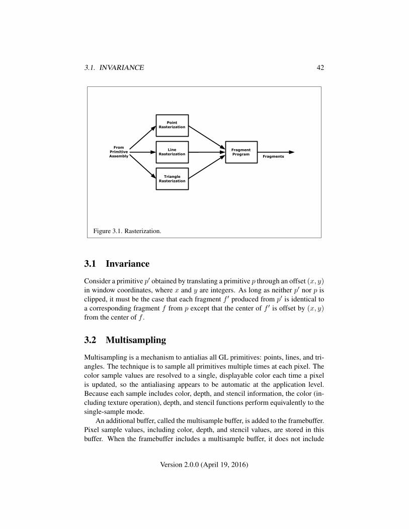
3.1. INVARIANCE 42
PointRasterization
TriangleRasterization
LineRasterization
FragmentProgram
FromPrimitiveAssembly Fragments
Figure 3.1. Rasterization.
3.1 Invariance
Consider a primitive p′ obtained by translating a primitive p through an offset (x, y)in window coordinates, where x and y are integers. As long as neither p′ nor p isclipped, it must be the case that each fragment f ′ produced from p′ is identical toa corresponding fragment f from p except that the center of f ′ is offset by (x, y)from the center of f .
3.2 Multisampling
Multisampling is a mechanism to antialias all GL primitives: points, lines, and tri-angles. The technique is to sample all primitives multiple times at each pixel. Thecolor sample values are resolved to a single, displayable color each time a pixelis updated, so the antialiasing appears to be automatic at the application level.Because each sample includes color, depth, and stencil information, the color (in-cluding texture operation), depth, and stencil functions perform equivalently to thesingle-sample mode.
An additional buffer, called the multisample buffer, is added to the framebuffer.Pixel sample values, including color, depth, and stencil values, are stored in thisbuffer. When the framebuffer includes a multisample buffer, it does not include
Version 2.0.0 (April 19, 2016)
3.2. MULTISAMPLING 43
depth or stencil buffers, even if the multisample buffer does not store depth orstencil values. The color buffer coexists with the multisample buffer, however.
Multisample antialiasing is most valuable for rendering triangles, because itrequires no sorting for hidden surface elimination, and it correctly handles adjacenttriangles, object silhouettes, and even intersecting triangles.
If the value of SAMPLE_BUFFERS is one, the rasterization of all primitivesis changed, and is referred to as multisample rasterization. Otherwise, primitiverasterization is referred to as single-sample rasterization. The value of SAMPLE_-BUFFERS is queried by calling GetIntegerv with pname set to SAMPLE_BUFFERS.
During multisample rendering the contents of a pixel fragment are changedin two ways. First, each fragment includes a coverage value with SAMPLES bits.The value of SAMPLES is an implementation-dependent constant, and is queried bycalling GetIntegerv with pname set to SAMPLES.
Second, each fragment includes SAMPLES depth values, and sets of varyingvalues, instead of the single depth value and set of varying values that is main-tained in single-sample rendering mode. An implementation may choose to assignthe same set of varying values to more than one sample. The location for evalu-ating the varying values can be anywhere within the pixel including the fragmentcenter or any of the sample locations. The varying values need not be evaluated atthe same location. Each pixel fragment thus consists of integer x and y grid coor-dinates, SAMPLES sets of varying values, and a coverage value with a maximum ofSAMPLES bits.
Multisample rasterization cannot be enabled or disabled after a GL contextis created. It is enabled if the value of SAMPLE_BUFFERS is one, and disabledotherwise 1.
Multisample rasterization of all primitives differs substantially from single-sample rasterization. It is understood that each pixel in the framebuffer hasSAMPLES locations associated with it. These locations are exact positions, ratherthan regions or areas, and each is referred to as a sample point. The sample pointsassociated with a pixel may be located inside or outside of the unit square that isconsidered to bound the pixel. Furthermore, the relative locations of sample pointsmay be identical for each pixel in the framebuffer, or they may differ.
If the sample locations differ per pixel, they should be aligned to window, notscreen, boundaries. Otherwise rendering results will be window-position specific.The invariance requirement described in section 3.1 is relaxed for all multisamplerasterization, because the sample locations may be a function of pixel location.
1When using EGL to create OpenGL SC context and surfaces, for example, multisample rasteri-zation is enabled when the EGLConfig used to create a context and surface supports a multisamplebuffer.
Version 2.0.0 (April 19, 2016)
3.3. POINTS 44
It is not possible to query the actual sample locations of a pixel.
3.3 Points
Point size is taken from the shader builtin gl_PointSize and clamped to theimplementation-dependent point size range. The range is determined by theALIASED_POINT_SIZE_RANGE and may be queried as described in chapter 6.The maximum point size supported must be at least one.
Point rasterization produces a fragment for each framebuffer pixel whose cen-ter lies inside a square centered at the point’s (xw, yw), with side length equal tothe point size.
All fragments produced in rasterizing a point are assigned the same associateddata, which are those of the vertex corresponding to the point. However, the gl_-PointCoord fragment shader input defines a per-fragment coordinate space (s, t)where s varies from 0 to 1 across the point horizontally left-to-right, and t rangesfrom 0 to 1 across the point vertically top-to-bottom.
The following formulas are used to evaluate (s, t) values:
s =1
2+xf + 1
2 − xwsize
t =1
2−yf + 1
2 − ywsize
where size is the point’s size, xf and yf are the (integral) window coordinatesof the fragment, and xw and yw are the exact, unrounded window coordinates ofthe vertex for the point.
3.3.1 Point Multisample Rasterization
If the value of SAMPLE_BUFFERS is one, then points are rasterized using the fol-lowing algorithm. Point rasterization produces a fragment for each framebufferpixel with one or more sample points that intersect a region centered at the point’s(xw, yw). This region is a square with side length equal to the point size. Coveragebits that correspond to sample points that intersect the region are 1, other cover-age bits are 0. All data associated with each sample for the fragment are the dataassociated with the point being rasterized.
The set of point sizes supported is equivalent to those for points without multi-sample.
Version 2.0.0 (April 19, 2016)
3.4. LINE SEGMENTS 45
3.4 Line Segments
A line segment results from a line strip, a line loop, or a series of separate linesegments. Line width may be set by calling
void LineWidth( float width );
with an appropriate positive width to control the width of rasterized line seg-ments. The default width is 1.0. Values less than or equal to 0.0 generate theerror INVALID_VALUE.
3.4.1 Basic Line Segment Rasterization
Line segment rasterization begins by characterizing the segment as either x-majoror y-major. x-major line segments have slope in the closed interval [−1, 1]; allother line segments are y-major (slope is determined by the segment’s endpoints).We shall specify rasterization only for x-major segments except in cases where themodifications for y-major segments are not self-evident.
Ideally, the GL uses a “diamond-exit” rule to determine those fragments thatare produced by rasterizing a line segment. For each fragment f with center at win-dow coordinates xf and yf , define a diamond-shaped region that is the intersectionof four half planes:
Rf = { (x, y) | |x− xf |+ |y − yf | < 1/2.}
Essentially, a line segment starting at pa and ending at pb produces those frag-ments f for which the segment intersects Rf , except if pb is contained in Rf . Seefigure 3.2.
To avoid difficulties when an endpoint lies on a boundary of Rf we (in princi-ple) perturb the supplied endpoints by a tiny amount. Let pa and pb have windowcoordinates (xa, ya) and (xb, yb), respectively. Obtain the perturbed endpoints p′agiven by (xa, ya) − (ε, ε2) and p′b given by (xb, yb) − (ε, ε2). Rasterizing the linesegment starting at pa and ending at pb produces those fragments f for which thesegment starting at p′a and ending on p′b intersects Rf , except if p′b is contained inRf . ε is chosen to be so small that rasterizing the line segment produces the samefragments when δ is substituted for ε for any 0 < δ ≤ ε.
When pa and pb lie on fragment centers, this characterization of fragmentsreduces to Bresenham’s algorithm with one modification: lines produced in thisdescription are “half-open,” meaning that the final fragment (corresponding to pb)is not drawn. This means that when rasterizing a series of connected line segments,
Version 2.0.0 (April 19, 2016)
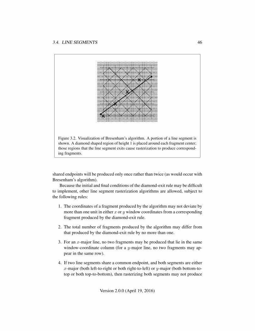
3.4. LINE SEGMENTS 46
� � � � �� � � � �� � � � �� � � � �
� � � � �� � � � �� � � � �� � � � �
� � � � �� � � � �� � � � �� � � � �
� � � � �� � � � �� � � � �� � � � �
� � � � �� � � � �� � � � �� � � � �
� � � � �� � � � �� � � � �� � � � �� � � � �� � � � �� � � � �� � � � �� � � � �� � � � �� � � � �� � � � �� � � � �� � � � �� � � � �� � � � �
� � � � �� � � � �� � � � �� � � � �� � � � �� � � � �� � � � �� � � � �
� � � � �� � � � �� � � � �� � � � �
� � � � �� � � � �� � � � �� � � � �� � � � �� � � � �� � � � �� � � � �� � � � �� � � � �� � � � �� � � � �� � � � �� � � � �� � � � �� � � � �� � � � �� � � � �� � � � �� � � � �
� � � � �� � � � �� � � � �� � � � �� � � � �� � � � �� � � � �� � � � �� � � � �� � � � �� � � � �� � � � �� � � � �� � � � �� � � � �� � � � �� � � � �� � � � �� � � � �� � � � �
Figure 3.2. Visualization of Bresenham’s algorithm. A portion of a line segment isshown. A diamond shaped region of height 1 is placed around each fragment center;those regions that the line segment exits cause rasterization to produce correspond-ing fragments.
shared endpoints will be produced only once rather than twice (as would occur withBresenham’s algorithm).
Because the initial and final conditions of the diamond-exit rule may be difficultto implement, other line segment rasterization algorithms are allowed, subject tothe following rules:
1. The coordinates of a fragment produced by the algorithm may not deviate bymore than one unit in either x or y window coordinates from a correspondingfragment produced by the diamond-exit rule.
2. The total number of fragments produced by the algorithm may differ fromthat produced by the diamond-exit rule by no more than one.
3. For an x-major line, no two fragments may be produced that lie in the samewindow-coordinate column (for a y-major line, no two fragments may ap-pear in the same row).
4. If two line segments share a common endpoint, and both segments are eitherx-major (both left-to-right or both right-to-left) or y-major (both bottom-to-top or both top-to-bottom), then rasterizing both segments may not produce
Version 2.0.0 (April 19, 2016)
3.4. LINE SEGMENTS 47
duplicate fragments, nor may any fragments be omitted so as to interruptcontinuity of the connected segments.
Next we must specify how the data associated with each rasterized fragmentare obtained. Let the window coordinates of a produced fragment center be givenby pr = (xd, yd) and let pa = (xa, ya) and pb = (xb, yb). Set
t =(pr − pa) · (pb − pa)
‖pb − pa‖2. (3.1)
(Note that t = 0 at pa and t = 1 at pb.) The value of an associated datum f forthe fragment, whether it be the clip w coordinate or an element of a vertex shadervarying output, is found as
f =(1− t)fa/wa + tfb/wb
(1− t)/wa + t/wb(3.2)
where fa and fb are the data associated with the starting and ending endpoints ofthe segment, respectively; wa and wb are the clip w coordinates of the starting andending endpoints of the segments, respectively. However, the depth value, windowz, must be found using linear interpolation:
f = (1− t)fa + tfb. (3.3)
3.4.2 Other Line Segment Features
We have just described the rasterization of non-antialiased line segments of widthone. We now describe the rasterization of line segments for general values of theline segment rasterization parameters.
Wide Lines
The actual width of non-antialiased lines is determined by rounding the suppliedwidth to the nearest integer, then clamping it to the implementation-dependentmaximum non-antialiased line width. This implementation-dependent value mustbe no less than one. If rounding the specified width results in the value 0, then it isas if the value were 1.
Non-antialiased line segments of width other than one are rasterized by off-setting them in the minor direction (for an x-major line, the minor direction isy, and for a y-major line, the minor direction is x) and replicating fragments inthe minor direction (see figure 3.3). Let w be the width rounded to the nearestinteger (if w = 0, then it is as if w = 1). If the line segment has endpoints
Version 2.0.0 (April 19, 2016)
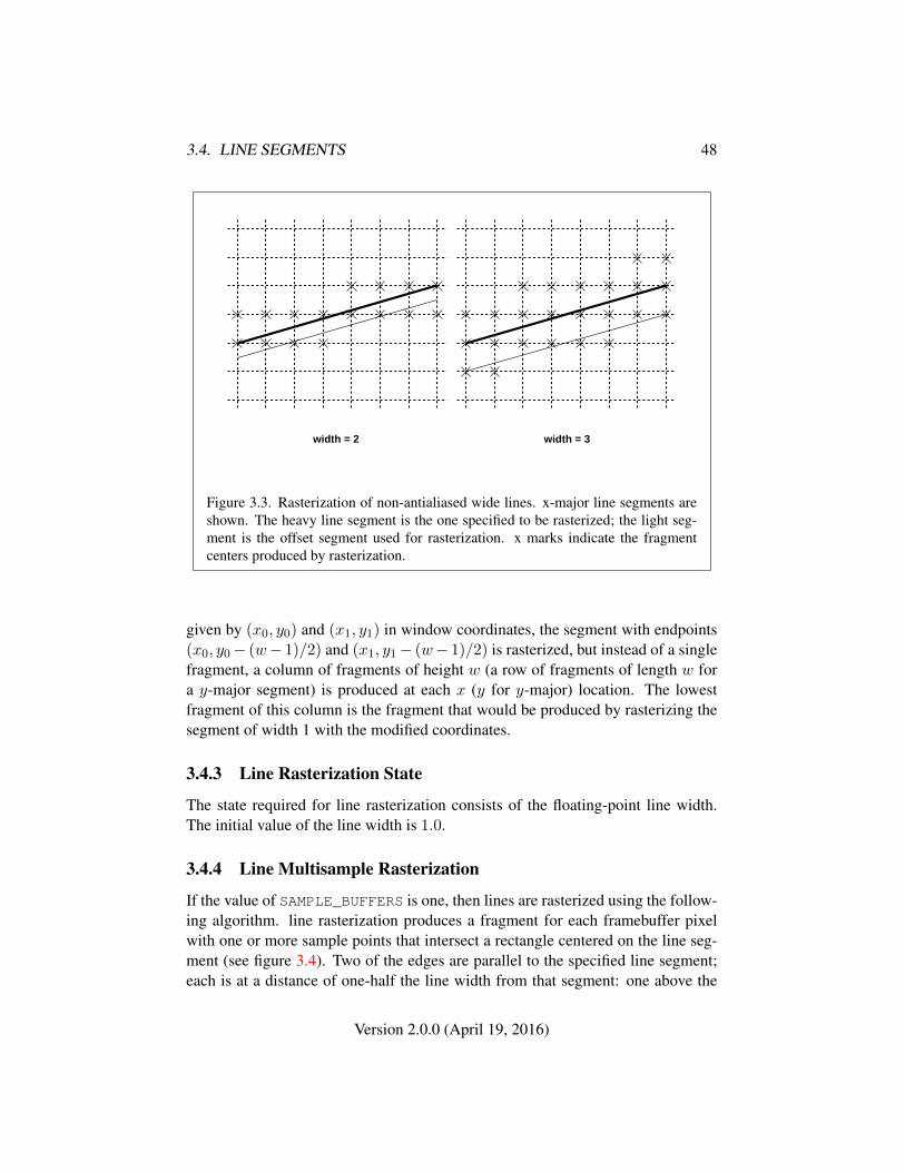
3.4. LINE SEGMENTS 48
width = 2 width = 3
Figure 3.3. Rasterization of non-antialiased wide lines. x-major line segments areshown. The heavy line segment is the one specified to be rasterized; the light seg-ment is the offset segment used for rasterization. x marks indicate the fragmentcenters produced by rasterization.
given by (x0, y0) and (x1, y1) in window coordinates, the segment with endpoints(x0, y0− (w− 1)/2) and (x1, y1− (w− 1)/2) is rasterized, but instead of a singlefragment, a column of fragments of height w (a row of fragments of length w fora y-major segment) is produced at each x (y for y-major) location. The lowestfragment of this column is the fragment that would be produced by rasterizing thesegment of width 1 with the modified coordinates.
3.4.3 Line Rasterization State
The state required for line rasterization consists of the floating-point line width.The initial value of the line width is 1.0.
3.4.4 Line Multisample Rasterization
If the value of SAMPLE_BUFFERS is one, then lines are rasterized using the follow-ing algorithm. line rasterization produces a fragment for each framebuffer pixelwith one or more sample points that intersect a rectangle centered on the line seg-ment (see figure 3.4). Two of the edges are parallel to the specified line segment;each is at a distance of one-half the line width from that segment: one above the
Version 2.0.0 (April 19, 2016)
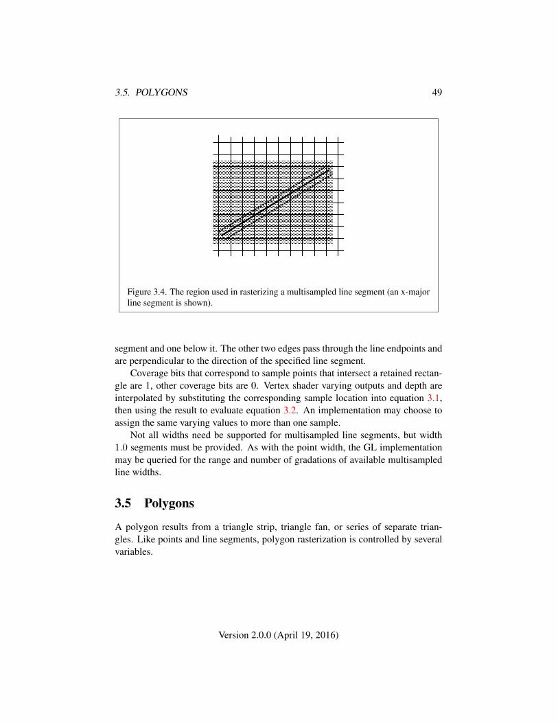
3.5. POLYGONS 49
� � � � � � � � � � � � � � � � � � � �� � � � � � � � � � � � � � � � � � � �� � � � � � � � � � � � � � � � � � � �� � � � � � � � � � � � � � � � � � � �� � � � � � � � � � � � � � � � � � � �� � � � � � � � � � � � � � � � � � � �� � � � � � � � � � � � � � � � � � � �� � � � � � � � � � � � � � � � � � � �� � � � � � � � � � � � � � � � � � � �� � � � � � � � � � � � � � � � � � � �� � � � � � � � � � � � � � � � � � � �� � � � � � � � � � � � � � � � � � � �� � � � � � � � � � � � � � � � � � � �� � � � � � � � � � � � � � � � � � � �
Figure 3.4. The region used in rasterizing a multisampled line segment (an x-majorline segment is shown).
segment and one below it. The other two edges pass through the line endpoints andare perpendicular to the direction of the specified line segment.
Coverage bits that correspond to sample points that intersect a retained rectan-gle are 1, other coverage bits are 0. Vertex shader varying outputs and depth areinterpolated by substituting the corresponding sample location into equation 3.1,then using the result to evaluate equation 3.2. An implementation may choose toassign the same varying values to more than one sample.
Not all widths need be supported for multisampled line segments, but width1.0 segments must be provided. As with the point width, the GL implementationmay be queried for the range and number of gradations of available multisampledline widths.
3.5 Polygons
A polygon results from a triangle strip, triangle fan, or series of separate trian-gles. Like points and line segments, polygon rasterization is controlled by severalvariables.
Version 2.0.0 (April 19, 2016)
3.5. POLYGONS 50
3.5.1 Basic Polygon Rasterization
The first step of polygon rasterization is to determine if the polygon is back facingor front facing. This determination is made based on the sign of the (clipped orunclipped) polygon’s area computed in window coordinates. One way to computethis area is
a =1
2
n−1∑i=0
xiwyi⊕1w − xi⊕1w yiw (3.4)
where xiw and yiw are the x and y window coordinates of the ith vertex ofthe n-vertex polygon (vertices are numbered starting at zero for purposes of thiscomputation) and i⊕1 is (i+1) mod n. The interpretation of the sign of this valueis controlled with
void FrontFace( enum dir );
Setting dir to CCW (corresponding to counter-clockwise orientation of the pro-jected polygon in window coordinates) indicates that the sign of a should be re-versed prior to use. Setting dir to CW (corresponding to clockwise orientation)uses the sign of a is as computed above. Front face determination requires one bitof state, and is initially set to CCW.
If the sign of the area computed by equation 3.4 (including the possible reversalof this sign as indicated by the last call to FrontFace) is positive, the polygon isfront facing; otherwise, it is back facing. This determination is used in conjunctionwith the CullFace enable bit and mode value to decide whether or not a particularpolygon is rasterized. The CullFace mode is set by calling
void CullFace( enum mode );
mode is a symbolic constant: one of FRONT, BACK or FRONT_AND_BACK. Cullingis enabled or disabled with Enable or Disable using the symbolic constant CULL_-FACE. Front facing polygons are rasterized if either culling is disabled or the Cull-Face mode is BACK while back facing polygons are rasterized only if either cullingis disabled or the CullFace mode is FRONT. The initial setting of the CullFacemode is BACK. Initially, culling is disabled.
The rule for determining which fragments are produced by polygon rasteriza-tion is called point sampling. The two-dimensional projection obtained by takingthe x and y window coordinates of the polygon’s vertices is formed. Fragmentcenters that lie inside of this polygon are produced by rasterization. Special treat-ment is given to a fragment whose center lies on a polygon boundary edge. In
Version 2.0.0 (April 19, 2016)
3.5. POLYGONS 51
such a case we require that if two polygons lie on either side of a common edge(with identical endpoints) on which a fragment center lies, then exactly one of thepolygons results in the production of the fragment during rasterization.
As for the data associated with each fragment produced by rasterizing a poly-gon, we begin by specifying how these values are produced for fragments in atriangle. Define barycentric coordinates for a triangle. Barycentric coordinates area set of three numbers, a, b, and c, each in the range [0, 1], with a + b + c = 1.These coordinates uniquely specify any point p within the triangle or on the trian-gle’s boundary as
p = apa + bpb + cpc,
where pa, pb, and pc are the vertices of the triangle. a, b, and c can be found as
a =A(ppbpc)
A(papbpc), b =
A(ppapc)
A(papbpc), c =
A(ppapb)
A(papbpc),
where A(lmn) denotes the area in window coordinates of the triangle with verticesl, m, and n.
Denote a datum at pa, pb, or pc as fa, fb, or fc, respectively. Then the value fof a datum at a fragment produced by rasterizing a triangle is given by
f =afa/wa + bfb/wb + cfc/wc
a/wa + b/wb + c/wc(3.5)
where wa, wb and wc are the clip w coordinates of pa, pb, and pc, respectively.a, b, and c are the barycentric coordinates of the fragment for which the data areproduced. a, b, and c must correspond precisely to the exact coordinates of thecenter of the fragment. Another way of saying this is that the data associated witha fragment must be sampled at the fragment’s center.
Just as with line segment rasterization, the depth value, window z, must befound using linear interpolation:
f = afa + bfb + cfc
3.5.2 Depth Offset
The depth values of all fragments generated by the rasterization of a polygon maybe offset by a single value that is computed for that polygon. The function thatdetermines this value is specified by calling
void PolygonOffset( float factor, float units );
Version 2.0.0 (April 19, 2016)
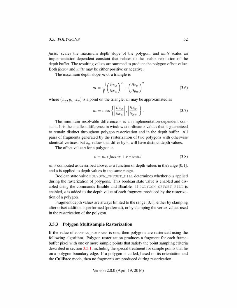
3.5. POLYGONS 52
factor scales the maximum depth slope of the polygon, and units scales animplementation-dependent constant that relates to the usable resolution of thedepth buffer. The resulting values are summed to produce the polygon offset value.Both factor and units may be either positive or negative.
The maximum depth slope m of a triangle is
m =
√(∂zw∂xw
)2
+
(∂zw∂yw
)2
(3.6)
where (xw, yw, zw) is a point on the triangle. m may be approximated as
m = max
{∣∣∣∣ ∂zw∂xw
∣∣∣∣ , ∣∣∣∣∂zw∂yw
∣∣∣∣} . (3.7)
The minimum resolvable difference r is an implementation-dependent con-stant. It is the smallest difference in window coordinate z values that is guaranteedto remain distinct throughout polygon rasterization and in the depth buffer. Allpairs of fragments generated by the rasterization of two polygons with otherwiseidentical vertices, but zw values that differ by r, will have distinct depth values.
The offset value o for a polygon is
o = m ∗ factor + r ∗ units. (3.8)
m is computed as described above, as a function of depth values in the range [0,1],and o is applied to depth values in the same range.
Boolean state value POLYGON_OFFSET_FILL determines whether o is appliedduring the rasterization of polygons. This boolean state value is enabled and dis-abled using the commands Enable and Disable. If POLYGON_OFFSET_FILL isenabled, o is added to the depth value of each fragment produced by the rasteriza-tion of a polygon.
Fragment depth values are always limited to the range [0,1], either by clampingafter offset addition is performed (preferred), or by clamping the vertex values usedin the rasterization of the polygon.
3.5.3 Polygon Multisample Rasterization
If the value of SAMPLE_BUFFERS is one, then polygons are rasterized using thefollowing algorithm. Polygon rasterization produces a fragment for each frame-buffer pixel with one or more sample points that satisfy the point sampling criteriadescribed in section 3.5.1, including the special treatment for sample points that lieon a polygon boundary edge. If a polygon is culled, based on its orientation andthe CullFace mode, then no fragments are produced during rasterization.
Version 2.0.0 (April 19, 2016)
3.6. PIXEL RECTANGLES 53
Coverage bits that correspond to sample points that satisfy the point samplingcriteria are 1, other coverage bits are 0. Vertex shader varying outputs and depth areinterpolated by substituting the corresponding sample location into the barycentricequations described in section 3.5.1, using equation 3.5 or its approximation thatomits w components. An implementation may choose to assign the same set ofvarying values to more than one sample by barycentric evaluation using any loca-tion within the pixel including the fragment center or one of the sample locations.
3.5.4 Polygon Rasterization State
The state required for polygon rasterization consists of the factor and bias valuesof the polygon offset equation. The initial polygon offset factor and bias values areboth 0; initially polygon offset is disabled.
3.6 Pixel Rectangles
Rectangles of color values may be specified to the GL using TexSubImage2D andrelated commands described in section 3.7.1. Some of the parameters and oper-ations governing the operation of TexSubImage2D are shared by ReadnPixels(used to obtain pixel values from the framebuffer); the discussion of ReadnPixels,however, is deferred until section 4.3, after the framebuffer has been discussed indetail. Nevertheless, we note in this section when parameters and state pertainingto TexSubImage2D also pertain to ReadnPixels.
This section describes only how these rectangles are defined in client memory,and the steps involved in transferring pixel rectangles from client memory to theGL or vice-versa.
Parameters controlling the encoding of pixels in client memory (for readingand writing) are set with the command PixelStorei.
3.6.1 Pixel Storage Modes
Pixel storage modes affect the operation of TexSubImage2D and ReadnPixels (aswell as other commands; see section 3.7) when one of these commands is issued.Pixel storage modes are set with the command
void PixelStorei( enum pname, T param );
pname is a symbolic constant indicating a parameter to be set, and param is thevalue to set it to. Table 3.1 summarizes the pixel storage parameters, their types,their initial values, and their allowable ranges. Setting a parameter to a value out-side the given range results in the error INVALID_VALUE.
Version 2.0.0 (April 19, 2016)
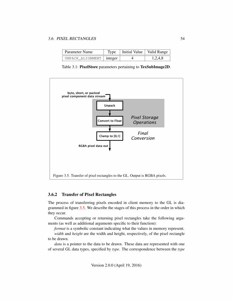
3.6. PIXEL RECTANGLES 54
Parameter Name Type Initial Value Valid RangeUNPACK_ALIGNMENT integer 4 1,2,4,8
Table 3.1: PixelStore parameters pertaining to TexSubImage2D.
Unpack
byte, short, or packedpixel component data stream
Convert to Float
Clamp to [0,1]
RGBA pixel data out
Pixel StorageOperations
FinalConversion
Figure 3.5. Transfer of pixel rectangles to the GL. Output is RGBA pixels.
3.6.2 Transfer of Pixel Rectangles
The process of transferring pixels encoded in client memory to the GL is dia-grammed in figure 3.5. We describe the stages of this process in the order in whichthey occur.
Commands accepting or returning pixel rectangles take the following argu-ments (as well as additional arguments specific to their function):
format is a symbolic constant indicating what the values in memory represent.width and height are the width and height, respectively, of the pixel rectangle
to be drawn.data is a pointer to the data to be drawn. These data are represented with one
of several GL data types, specified by type. The correspondence between the type
Version 2.0.0 (April 19, 2016)
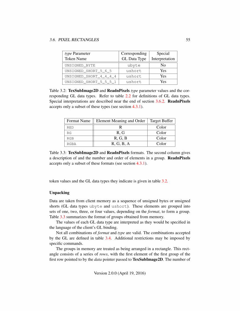
3.6. PIXEL RECTANGLES 55
type Parameter Corresponding SpecialToken Name GL Data Type InterpretationUNSIGNED_BYTE ubyte NoUNSIGNED_SHORT_5_6_5 ushort YesUNSIGNED_SHORT_4_4_4_4 ushort YesUNSIGNED_SHORT_5_5_5_1 ushort Yes
Table 3.2: TexSubImage2D and ReadnPixels type parameter values and the cor-responding GL data types. Refer to table 2.2 for definitions of GL data types.Special interpretations are described near the end of section 3.6.2. ReadnPixelsaccepts only a subset of these types (see section 4.3.1).
Format Name Element Meaning and Order Target BufferRED R ColorRG R, G ColorRGB R, G, B ColorRGBA R, G, B, A Color
Table 3.3: TexSubImage2D and ReadnPixels formats. The second column givesa description of and the number and order of elements in a group. ReadnPixelsaccepts only a subset of these formats (see section 4.3.1).
token values and the GL data types they indicate is given in table 3.2.
Unpacking
Data are taken from client memory as a sequence of unsigned bytes or unsignedshorts (GL data types ubyte and ushort). These elements are grouped intosets of one, two, three, or four values, depending on the format, to form a group.Table 3.3 summarizes the format of groups obtained from memory.
The values of each GL data type are interpreted as they would be specified inthe language of the client’s GL binding.
Not all combinations of format and type are valid. The combinations acceptedby the GL are defined in table 3.4. Additional restrictions may be imposed byspecific commands.
The groups in memory are treated as being arranged in a rectangle. This rect-angle consists of a series of rows, with the first element of the first group of thefirst row pointed to by the data pointer passed to TexSubImage2D. The number of
Version 2.0.0 (April 19, 2016)
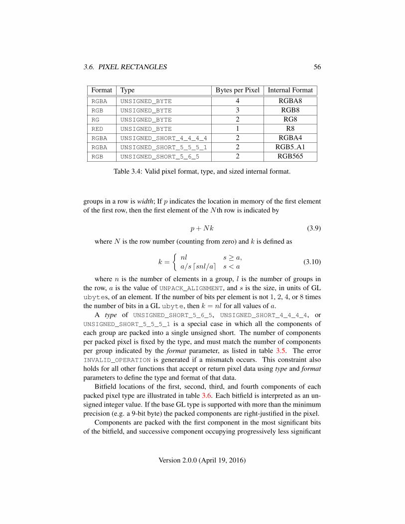
3.6. PIXEL RECTANGLES 56
Format Type Bytes per Pixel Internal FormatRGBA UNSIGNED_BYTE 4 RGBA8RGB UNSIGNED_BYTE 3 RGB8RG UNSIGNED_BYTE 2 RG8RED UNSIGNED_BYTE 1 R8RGBA UNSIGNED_SHORT_4_4_4_4 2 RGBA4RGBA UNSIGNED_SHORT_5_5_5_1 2 RGB5 A1RGB UNSIGNED_SHORT_5_6_5 2 RGB565
Table 3.4: Valid pixel format, type, and sized internal format.
groups in a row is width; If p indicates the location in memory of the first elementof the first row, then the first element of the N th row is indicated by
p+Nk (3.9)
where N is the row number (counting from zero) and k is defined as
k =
{nl s ≥ a,a/s dsnl/ae s < a
(3.10)
where n is the number of elements in a group, l is the number of groups inthe row, a is the value of UNPACK_ALIGNMENT, and s is the size, in units of GLubytes, of an element. If the number of bits per element is not 1, 2, 4, or 8 timesthe number of bits in a GL ubyte, then k = nl for all values of a.
A type of UNSIGNED_SHORT_5_6_5, UNSIGNED_SHORT_4_4_4_4, orUNSIGNED_SHORT_5_5_5_1 is a special case in which all the components ofeach group are packed into a single unsigned short. The number of componentsper packed pixel is fixed by the type, and must match the number of componentsper group indicated by the format parameter, as listed in table 3.5. The errorINVALID_OPERATION is generated if a mismatch occurs. This constraint alsoholds for all other functions that accept or return pixel data using type and formatparameters to define the type and format of that data.
Bitfield locations of the first, second, third, and fourth components of eachpacked pixel type are illustrated in table 3.6. Each bitfield is interpreted as an un-signed integer value. If the base GL type is supported with more than the minimumprecision (e.g. a 9-bit byte) the packed components are right-justified in the pixel.
Components are packed with the first component in the most significant bitsof the bitfield, and successive component occupying progressively less significant
Version 2.0.0 (April 19, 2016)

3.6. PIXEL RECTANGLES 57
type Parameter GL Data Number of MatchingToken Name Type Components Pixel FormatsUNSIGNED_SHORT_5_6_5 ushort 3 RGB
UNSIGNED_SHORT_4_4_4_4 ushort 4 RGBA
UNSIGNED_SHORT_5_5_5_1 ushort 4 RGBA
Table 3.5: Packed pixel formats.
locations. The most significant bit of each component is packed in the most signif-icant bit location of its location in the bitfield.
UNSIGNED_SHORT_5_6_5:
15 14 13 12 11 10 9 8 7 6 5 4 3 2 1 0
1st Component 2nd 3rd
UNSIGNED_SHORT_4_4_4_4:
15 14 13 12 11 10 9 8 7 6 5 4 3 2 1 0
1st Component 2nd 3rd 4th
UNSIGNED_SHORT_5_5_5_1:
15 14 13 12 11 10 9 8 7 6 5 4 3 2 1 0
1st Component 2nd 3rd 4th
Table 3.6: UNSIGNED_SHORT formats
Version 2.0.0 (April 19, 2016)
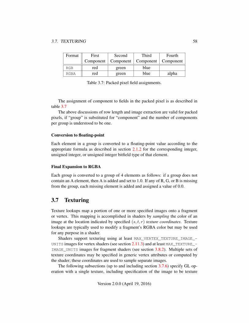
3.7. TEXTURING 58
Format First Second Third FourthComponent Component Component Component
RGB red green blueRGBA red green blue alpha
Table 3.7: Packed pixel field assignments.
The assignment of component to fields in the packed pixel is as described intable 3.7
The above discussions of row length and image extraction are valid for packedpixels, if “group” is substituted for “component” and the number of componentsper group is understood to be one.
Conversion to floating-point
Each element in a group is converted to a floating-point value according to theappropriate formula as described in section 2.1.2 for the corresponding integer,unsigned integer, or unsigned integer bitfield type of that element.
Final Expansion to RGBA
Each group is converted to a group of 4 elements as follows: if a group does notcontain an A element, then A is added and set to 1.0. If any of R, G, or B is missingfrom the group, each missing element is added and assigned a value of 0.0.
3.7 Texturing
Texture lookups map a portion of one or more specified images onto a fragmentor vertex. This mapping is accomplished in shaders by sampling the color of animage at the location indicated by specified (s, t, r) texture coordinates. Texturelookups are typically used to modify a fragment’s RGBA color but may be usedfor any purpose in a shader.
Shaders support texturing using at least MAX_VERTEX_TEXTURE_IMAGE_-UNITS images for vertex shaders (see section 2.11.3) and at least MAX_TEXTURE_-IMAGE_UNITS images for fragment shaders (see section 3.8.2). Multiple sets oftexture coordinates may be specified in generic vertex attributes or computed bythe shader; these coordinates are used to sample separate images.
The following subsections (up to and including section 3.7.6) specify GL op-eration with a single texture, including specification of the image to be texture
Version 2.0.0 (April 19, 2016)
3.7. TEXTURING 59
mapped and the means by which the image is filtered when sampled. The opera-tions described here are applied separately for each texture sampled by a shader.
The details of sampling a texture within a shader are described in the OpenGLES Shading Language Specification.
The command
void ActiveTexture( enum texture );
specifies the active texture image unit selector, ACTIVE_TEXTURE. Each textureimage unit consists of all the texture state defined in section 3.7.
The active texture unit selector selects the texture image unit accessed bycommands involving texture image processing defined in section 3.7. Suchcommands include all variants of TexSubImage2D commands, BindTexture,and queries of all such state. If the texture image unit number correspond-ing to the current value of ACTIVE_TEXTURE is greater than or equal to theimplementation-dependent constant MAX_COMBINED_TEXTURE_IMAGE_UNITS,the error INVALID_OPERATION is generated by any such command.
ActiveTexture generates the error INVALID_ENUM if an invalid texture is spec-ified. texture is a symbolic constant of the form TEXTUREi, indicating that textureimage unit i is to be modified. The constants obey TEXTUREi = TEXTURE0 + i,where i is in the range 0 to MAX_COMBINED_TEXTURE_IMAGE_UNITS− 1.
The state required for the active texture image unit selector is a single integer.The initial value is TEXTURE0.
3.7.1 Texture Image Specification
The command
void TexStorage2D( enum target, int level,int internalformat, sizei width, sizei height );
is provided for specifying the properties of all levels of a two-dimensional texture atonce. Once a texture is specified, the format and dimensions of all levels becomesimmutable. The contents of the images and the parameters can still be modified.Such a texture is referred to as an immutable-format texture. The immutabilitystatus of a texture can be determined by calling GetTexParameter with pnameTEXTURE_IMMUTABLE_FORMAT. Cube map textures are not supported.
If the command is successful, TEXTURE_IMMUTABLE_FORMAT becomes TRUE.If internalformat is a compressed texture format, then references to TexSubIm-age2D should be replaced by CompressedTexSubImage2D, with format, type anddata replaced by any valid imageSize and data.
TexStorage2D will generate the following errors:
Version 2.0.0 (April 19, 2016)
3.7. TEXTURING 60
• An INVALID_OPERATION error is generated if zero is bound to target.
• An INVALID_VALUE error is generated if width, height, or levels are lessthan 1.
• An INVALID_ENUM error is generated if internalformat is not one of thesized internal formats listed in table 3.4.
• An INVALID_OPERATION error is generated if levels is greater thanfloor(log2(max(width, height))) + 1.
• An INVALID_OPERATION error is generated if levels is not one and widthor height is not a power of two.
• After a successful call to TexStorage2D, an INVALID_OPERATION error isgenerated if TexStorage2D is called with the same texture, even if it doesnot affect the dimensions or format.
If an error is generated then the command will have no effect. After a suc-cessful call to any TexStorage command, no further changes to the dimensions orformat of the texture object may be made. Other commands may only alter thetexel values and texture parameters.
The GL stores the resulting texture with internal component resolutions of itsown choosing. The allocation of internal component resolution may vary basedon any TexStorage2D parameter (except target), but the allocation must not be afunction of any other state and cannot be changed once established. Allocationmust be invariant; the same allocation must be chosen each time a texture image isspecified with the same parameter values.
The levels argument to TexStorage2D is an integer level-of-detail number.Levels of detail are discussed below, under Mipmapping. The main texture imagehas a level of detail number of 0 and is known as the level zero array (or the imagearray of level zero).
The maximum allowable width and height of a two-dimensional texture imagemust be at least 2k−lod for image arrays of level zero through k, where k is the logbase 2 of MAX_TEXTURE_SIZE. and lod is the level-of-detail of the image array.It may be zero for image arrays of any level-of-detail greater than k. The errorINVALID_VALUE is generated if the specified image is too large to be stored underany conditions.
3.7.2 Texture Image Specification Commands
A two-dimensional texture consists of a single two-dimensional texture image. Thegroups in memory are treated as being arranged in a rectangle. The rectangle is an
Version 2.0.0 (April 19, 2016)
3.7. TEXTURING 61
image, whose size and organization are specified by the width and height parame-ters to TexStorage2D.
The selected groups are processed as described in section 3.6.2, stopping afterfinal expansion to RGBA. Each R, G, B, or A value so generated is clamped to[0,1]. Components are then selected from the resulting R, G, B, or A values toobtain a texture with the base internal format specified by (or derived from) inter-nalformat. Table 3.4 summarizes the mapping of R, G, B, and A values to texturecomponents, as a function of the base internal format of the texture image. Specify-ing a combination of values for format, type, and internalformat that is not listed asa valid combination in table 3.4 generates the error INVALID_OPERATION. Rect-angular subregions of existing texture images may be respecified.
The command
void TexSubImage2D( enum target, int level, int xoffset,int yoffset, sizei width, sizei height, enum format,enum type, void *data );
can specify an entire region and also respecify a rectangular subregion of an ex-isting texture array. No change is made to the internalformat, width, or height,parameters of the specified texture array, nor is any change made to texel valuesoutside the specified subregion. The target argument of TexSubImage2D must beTEXTURE_2D.
The level parameter of each command specifies the level of the texture arraythat is modified. If level is less than zero or greater than the base 2 logarithm of themaximum texture width or height, the error INVALID_VALUE is generated.
TexSubImage2D arguments width and height, match the corresponding argu-ments to TexStorage2D, meaning that they accept the same values, and have thesame meanings.
TexSubImage2D arguments format and type must be a valid combination fromtable 3.4 and correspond to the internalformat value used for TexStorage2D.
Arguments xoffset and yoffset of TexSubImage2D specify the lower left texelcoordinates of a width-wide by height-high rectangular subregion of the texturearray address. Taking wt and ht to be the specified width and height of the texturearray, and taking x, y,w, and h to be the xoffset, yoffset, width, and height argumentvalues, any of the following relationships generates the error INVALID_VALUE:
x < 0
x+ w > wt
y < 0
Version 2.0.0 (April 19, 2016)
3.7. TEXTURING 62
y + h > ht
Counting from zero, the nth pixel group is assigned to the texel with internal integercoordinates [i, j], where
i = x+ (n mod w)
j = y + (b nwc mod h)
3.7.3 Compressed Texture Images
Texture images may also be specified or modified using image data already storedin a known compressed image format. The GL defines no specific compressedformats, but compressed formats may be defined by GL extensions. Online tex-ture compression is not supported. Instead applications must use an offline com-pressor and provide a pre-compressed texture in binary format. There is a mech-anism to obtain token values for compressed formats; the number of specificcompressed internal formats supported can be obtained by querying the valueof NUM_COMPRESSED_TEXTURE_FORMATS. The set of specific compressed in-ternal formats supported by the renderer can be obtained by querying the valueof COMPRESSED_TEXTURE_FORMATS. The only values returned by this query arethose corresponding to internalformat parameters accepted by TexStorage2D andsuitable for general-purpose usage. The renderer will not enumerate formats withrestrictions that need to be specifically understood prior to use.
The command
void CompressedTexSubImage2D( enum target, int level,int xoffset, int yoffset, sizei width, sizei height,enum format, sizei imageSize, void *data );
can specify an entire region and also respecify a rectangular subregion of an ex-isting texture array, with incoming data stored in a known compressed image for-mat. The target, level, xoffset, yoffset, width, height, and format parameters havethe same meaning as in TexSubImage2D. data points to compressed image datastored in the compressed image format corresponding to format.
Compressed texture images are treated as an array of imageSize ubytes be-ginning at address data. All pixel storage and pixel transfer modes are ignoredwhen decoding a compressed texture image. If the imageSize parameter is notconsistent with the format, dimensions, and contents of the compressed image, anINVALID_VALUE error results.
Version 2.0.0 (April 19, 2016)
3.7. TEXTURING 63
This command does not provide for image format conversion, so anINVALID_OPERATION error results if format does not match the internal formatof the texture image being modified. If the imageSize parameter is not consistentwith the format, dimensions, and contents of the compressed image (too little ortoo much data), an INVALID_VALUE error results.
Compressed internal formats may have additional restrictions on the use of thecompressed image specification calls or parameters. Any such restrictions will bedocumented in the specification defining the compressed internal format; violatingthese restrictions will result in an INVALID_OPERATION error.
Any restrictions imposed by specific compressed internal formats will be in-variant with respect to image contents, meaning that if the GL accepts and stores atexture image in compressed form, CompressedTexSubImage2D will accept anyproperly encoded compressed texture image of the same width, height, compressedimage size, and compressed internal format for storage at the same texture level.
Calling CompressedTexSubImage2D will result in an INVALID_OPERATIONerror if xoffset or yoffset is not equal to zero, or if width and height do not matchthe width and height of the texture, respectively. These restrictions may be relaxedfor specific compressed internal formats whose images are easily modified.
3.7.4 Texture Parameters
Various parameters control how the texture array is treated when specified orchanged, and when applied to a fragment. Each parameter is set by calling
void TexParameter{if}( enum target, enum pname, T param );void TexParameter{if}v( enum target, enum pname,
T params );
target is the target, which must be TEXTURE_2D. pname is a symbolic constantindicating the parameter to be set; the possible constants and corresponding pa-rameters are summarized in table 3.8. In the first form of the command, paramis a value to which to set a single-valued parameter; in the second form of thecommand, params is an array of parameters whose type depends on the parameterbeing set.
3.7.5 Texture Wrap Modes
Wrap modes defined by the values of TEXTURE_WRAP_S or TEXTURE_WRAP_Trespectively affect the interpretation of s and t texture coordinates. The effect ofeach mode is described below.
Version 2.0.0 (April 19, 2016)
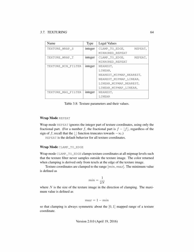
3.7. TEXTURING 64
Name Type Legal ValuesTEXTURE_WRAP_S integer CLAMP_TO_EDGE, REPEAT,
MIRRORED_REPEAT
TEXTURE_WRAP_T integer CLAMP_TO_EDGE, REPEAT,MIRRORED_REPEAT
TEXTURE_MIN_FILTER integer NEAREST,LINEAR,NEAREST_MIPMAP_NEAREST,NEAREST_MIPMAP_LINEAR,LINEAR_MIPMAP_NEAREST,LINEAR_MIPMAP_LINEAR,
TEXTURE_MAG_FILTER integer NEAREST,LINEAR
Table 3.8: Texture parameters and their values.
Wrap Mode REPEAT
Wrap mode REPEAT ignores the integer part of texture coordinates, using only thefractional part. (For a number f , the fractional part is f − bfc, regardless of thesign of f ; recall that the bc function truncates towards −∞.)
REPEAT is the default behavior for all texture coordinates.
Wrap Mode CLAMP_TO_EDGE
Wrap mode CLAMP_TO_EDGE clamps texture coordinates at all mipmap levels suchthat the texture filter never samples outside the texture image. The color returnedwhen clamping is derived only from texels at the edge of the texture image.
Texture coordinates are clamped to the range [min,max]. The minimum valueis defined as
min =1
2N
where N is the size of the texture image in the direction of clamping. The maxi-mum value is defined as
max = 1−min
so that clamping is always symmetric about the [0, 1] mapped range of a texturecoordinate.
Version 2.0.0 (April 19, 2016)

3.7. TEXTURING 65
Wrap Mode MIRRORED_REPEAT
Wrap mode MIRRORED_REPEAT first mirrors the texture coordinate, where mirror-ing a value f computes
mirror(f) =
{f − bfc, bfc is even1− (f − bfc), bfc is odd
The mirrored coordinate is then clamped as described above for wrap modeCLAMP_TO_EDGE.
3.7.6 Texture Minification
Applying a texture to a primitive implies a mapping from texture image space toframebuffer image space. In general, this mapping involves a reconstruction ofthe sampled texture image, followed by a homogeneous warping implied by themapping to framebuffer space, then a filtering, followed finally by a resamplingof the filtered, warped, reconstructed image before applying it to a fragment. Inthe GL this mapping is approximated by one of two simple filtering schemes. Oneof these schemes is selected based on whether the mapping from texture space toframebuffer space is deemed to magnify or minify the texture image.
Scale Factor and Level of Detail
The choice is governed by a scale factor ρ(x, y) and the level of detail parameterλ(x, y), defined as
λ(x, y) = log2[ρ(x, y)] (3.11)
If λ(x, y) is less than or equal to the constant c (described below in sec-tion 3.7.7) the texture is said to be magnified; if it is greater, the texture is minified.
Let s(x, y) be the function that associates an s texture coordinate with each setof window coordinates (x, y) that lie within a primitive; define t(x, y) analogously.Let u(x, y) = wt×s(x, y) and v(x, y) = ht×t(x, y), wherewt and ht are equal tothe width and height of the level zero array. For a polygon, ρ is given at a fragmentwith window coordinates (x, y) by
ρ = max
√(
∂u
∂x
)2
+
(∂v
∂x
)2
,
√(∂u
∂y
)2
+
(∂v
∂y
)2 (3.12)
where ∂u/∂x indicates the derivative of u with respect to window x, and similarlyfor the other derivatives.
Version 2.0.0 (April 19, 2016)
3.7. TEXTURING 66
For a line, the formula is
ρ =
√(∂u
∂x∆x+
∂u
∂y∆y
)2
+
(∂v
∂x∆x+
∂v
∂y∆y
)2/l, (3.13)
where ∆x = x2 − x1 and ∆y = y2 − y1 with (x1, y1) and (x2, y2) being thesegment’s window coordinate endpoints and l =
√∆x2 + ∆y2. For a point, ρ ≡
1.While it is generally agreed that equations 3.12 and 3.13 give the best results
when texturing, they are often impractical to implement. Therefore, an imple-mentation may approximate the ideal ρ with a function f(x, y) subject to theseconditions:
1. f(x, y) is continuous and monotonically increasing in each of |∂u/∂x|,|∂u/∂y|, |∂v/∂x|, |∂v/∂y|,
2. Let
mu = max
{∣∣∣∣∂u∂x∣∣∣∣ , ∣∣∣∣∂u∂y
∣∣∣∣}
mv = max
{∣∣∣∣∂v∂x∣∣∣∣ , ∣∣∣∣∂v∂y
∣∣∣∣}Then max{mu,mv} ≤ f(x, y) ≤ mu +mv.
When λ indicates minification, the value assigned to TEXTURE_MIN_FILTER
is used to determine how the texture value for a fragment is selected. WhenTEXTURE_MIN_FILTER is NEAREST, the texel in the level zero array that is near-est (in Manhattan distance) to that specified by (s, t) is obtained. This means thetexel at location (i, j) becomes the texture value, with i given by
i =
{buc, s < 1wt − 1, s = 1
(3.14)
(Recall that if TEXTURE_WRAP_S is REPEAT, then 0 ≤ s < 1.) Similarly, j isfound as
j =
{bvc, t < 1ht − 1, t = 1
(3.15)
Version 2.0.0 (April 19, 2016)
3.7. TEXTURING 67
When TEXTURE_MIN_FILTER is LINEAR, a 2× 2 square of texels in the levelzero array is selected. This square is obtained by first wrapping texture coordinatesas described in section 3.7.5, then computing
i0 =
{bu− 1/2c mod wt, TEXTURE_WRAP_S is REPEATbu− 1/2c, otherwise
and
j0 =
{bv − 1/2c mod ht, TEXTURE_WRAP_T is REPEATbv − 1/2c, otherwise
Then
i1 =
{(i0 + 1) mod wt, TEXTURE_WRAP_S is REPEATi0 + 1, otherwise
and
j1 =
{(j0 + 1) mod ht, TEXTURE_WRAP_T is REPEATj0 + 1, otherwise
Letα = frac(u− 1/2)
β = frac(v − 1/2)
where frac(x) denotes the fractional part of x.The texture value τ is found as
τ = (1− α)(1− β)τi0j0 + α(1− β)τi1j0 + (1− α)βτi0j1 + αβτi1j1 (3.16)
where τij is the texel at location (i, j) in the texture image.
Rendering Feedback Loops
A rendering feedback loop can occur when a texture is attached to an attachmentpoint of the currently bound framebuffer object. In this case rendering results areimplementation specific. The exact conditions are detailed in section 4.4.4.
Version 2.0.0 (April 19, 2016)
3.7. TEXTURING 68
Mipmapping
TEXTURE_MIN_FILTER values NEAREST_MIPMAP_NEAREST, NEAREST_-
MIPMAP_LINEAR, LINEAR_MIPMAP_NEAREST, and LINEAR_MIPMAP_LINEAR
each require the use of a mipmap. A mipmap is an ordered set of arrays represent-ing the same image; each array has a resolution lower than the previous one. If thelevel zero array has dimensions wb × hb, then there are blog2(max(wb, hb))c + 1image arrays in the mipmap. Each array subsequent to the level zero array hasdimensions
max(1, bwb
2ic)×max(1, bhb
2ic)c)
until the last array is reached with dimension 1× 1.Each array in a mipmap is defined using TexSubImage2D or CompressedTex-
SubImage2D; the array being set is indicated with the level-of-detail argumentlevel. Level-of-detail numbers proceed from zero for the original texture arraythrough q = blog2(max(wb, hb))c with each unit increase indicating an array ofhalf the dimensions of the previous one (rounded down to the next integer if frac-tional) as already described. All arrays from zero through q must be defined, asdiscussed in section 3.7.9.
If any dimension of any array in a mipmap is not a power of two (e.g. ifrounding down as described above is performed), then the mipmap is described asa non-power-of-two texture. Non-power-of-two textures have restrictions on theallowed texture wrap modes and filters, as described in section 3.8.2.
The mipmap is used in conjunction with the level of detail to approximate theapplication of an appropriately filtered texture to a fragment. Let c be the valueof λ at which the transition from minification to magnification occurs (since thisdiscussion pertains to minification, we are concerned only with values of λ whereλ > c).
For mipmap filters NEAREST_MIPMAP_NEAREST and LINEAR_MIPMAP_-
NEAREST, the dth mipmap array is selected, where
d =
0, λ ≤ 1
2dλ+ 1
2e − 1, λ > 12 , λ ≤ q + 1
2q, λ > q + 1
2
(3.17)
The rules for NEAREST or LINEAR filtering are then applied to the selectedarray.
For mipmap filters NEAREST_MIPMAP_LINEAR and LINEAR_MIPMAP_-
Version 2.0.0 (April 19, 2016)
3.7. TEXTURING 69
LINEAR, the level d1 and d2 mipmap arrays are selected, where
d1 =
{q, λ ≥ qbλc, otherwise
(3.18)
d2 =
{q, λ ≥ qd1 + 1, otherwise
(3.19)
The rules for NEAREST or LINEAR filtering are then applied to each of theselected arrays, yielding two corresponding texture values τ1 and τ2. The finaltexture value is then found as
τ = [1− frac(λ)]τ1 + frac(λ)τ2.
3.7.7 Texture Magnification
When λ indicates magnification, the value assigned to TEXTURE_MAG_FILTER
determines how the texture value is obtained. There are two possible valuesfor TEXTURE_MAG_FILTER: NEAREST and LINEAR. NEAREST behaves exactly asNEAREST for TEXTURE_MIN_FILTER (equations 3.14 and 3.15 are used); LINEARbehaves exactly as LINEAR for TEXTURE_MIN_FILTER (equation 3.16 is used).The level zero array is always used for magnification.
Finally, there is the choice of c, the minification vs. magnification switch-overpoint. If the magnification filter is given by LINEAR and the minification filter isgiven by NEAREST_MIPMAP_NEAREST or NEAREST_MIPMAP_LINEAR, then c =0.5. This is done to ensure that a minified texture does not appear “sharper” than amagnified texture. Otherwise c = 0.
3.7.8 Texture Framebuffer Attachment
The texture values are considered implementation specific if all of the followingconditions are true:
• The current FRAMEBUFFER_BINDING names an application-created frame-buffer object F .
• The texture is attached to one of the attachment points, A, of framebufferobject F .
• TEXTURE_MIN_FILTER is NEAREST or LINEAR, and the value ofFRAMEBUFFER_ATTACHMENT_TEXTURE_LEVEL for attachment point Ais zero; or, TEXTURE_MIN_FILTER is NEAREST_MIPMAP_NEAREST,
Version 2.0.0 (April 19, 2016)
3.7. TEXTURING 70
NEAREST_MIPMAP_LINEAR, LINEAR_MIPMAP_NEAREST, or LINEAR_-
MIPMAP_LINEAR, and the value of FRAMEBUFFER_ATTACHMENT_-
TEXTURE_LEVEL for attachment point A is within the inclusive range fromzero to last mip-level.
3.7.9 Texture Completeness and Non-Power-Of-Two Textures
A texture is said to be complete if all the image arrays and texture parametersrequired to utilize the texture for texture application are consistently defined.
A two-dimensional texture is complete if the following conditions all hold true:
• The set of mipmap arrays zero through q (where q is defined in the Mipmap-ping discussion of section 3.7.6) were each specified with the same format,internal format, and type.
• The dimensions of the arrays follow the sequence described in the Mipmap-ping discussion of section 3.7.6.
• Each dimension of the level zero array is positive.
Effects of Completeness on Texture Application
Texture lookups performed in vertex and fragment shaders are affected by com-pleteness of the texture being sampled as described in sections 2.11.3 and 3.8.2.
Effects of Completeness on Texture Image Specification
An implementation may allow a texture image array of level one or greater to becreated only if a complete set of image arrays consistent with the requested arraycan be supported.
3.7.10 Mipmap Generation
Mipmaps can be generated with the command
void GenerateMipmap( enum target );
target is the target, which must be TEXTURE_2D.GenerateMipmap computes a complete set of mipmap arrays (as defined in
section 3.7.9) derived from the level zero array. Array levels one through q arereplaced with the derived arrays, regardless of their previous contents. The levelzero array is left unchanged by this computation.
Version 2.0.0 (April 19, 2016)
3.7. TEXTURING 71
The internal formats of the derived mipmap arrays all match those of the levelzero array, and the dimensions of the derived arrays follow the requirements de-scribed in section 3.7.9.
The contents of the derived arrays are computed by repeated, filtered reductionof the level zero array. No particular filter algorithm is required, though a box filteris recommended as the default filter.
If either the width or height of the level zero array are not a power or two, theerror INVALID_OPERATION is generated.
If the level zero array is stored in a compressed internal format, the errorINVALID_OPERATION is generated.
3.7.11 Texture State
The state necessary for texture can be divided into two categories. First, there isthe mipmap array. Each array has associated with it a width and height, an integerdescribing the internal format of the image, an integer value describing the type ofeach of the components, a boolean describing whether the image is compressed ornot, and an integer size of a compressed image. Each initial texture array is null(zero width and height). Next, there is a set of texture properties; it consists ofthe selected minification and magnification filters, and the wrap modes for s andt. In the initial state, the value assigned to TEXTURE_MIN_FILTER is NEAREST_-MIPMAP_LINEAR, and the value for TEXTURE_MAG_FILTER is LINEAR. s and twrap modes are both set to REPEAT.
3.7.12 Texture Objects
The name space for texture objects is the unsigned integers, with zero reserved bythe GL.
A texture object is created by binding a texture object name obtained by callingGenTextures to TEXTURE_2D. Texture objects cannot be deleted.
The binding is effected by calling
void BindTexture( enum target, uint texture );
with target set to TEXTURE_2D and texture set to the texture object name obtainedfrom GenTextures. The resulting texture object is a new state vector, comprisingall the state values listed in section 3.7.11, set to the same initial values. CallingBindTexture with a texture object name not obtained by GenTextures will resultin a INVALID_OPERATION error.
Version 2.0.0 (April 19, 2016)
3.8. FRAGMENT SHADERS 72
BindTexture may also be used to bind an existing texture object. If the bindis successful no change is made to the state of the bound texture object, and anyprevious binding to target is broken.
While a texture object is bound, GL operations on the target to which it isbound affect the bound object, and queries of the target to which it is bound returnstate from the bound object.
In the initial state, TEXTURE_2D has a two-dimensional texture state vector as-sociated with it. In order that access to the initial texture not be lost, it is treated astexture object whose name is 0. The initial two-dimensional texture is therefore op-erated upon, queried, and applied as TEXTURE_2D 0 is bound to the correspondingtargets.
The command
void GenTextures( sizei n, uint *textures );
returns n previously unused texture object names in textures. These names aremarked as used, for the purposes of GenTextures only, but they acquire texturestate only when they are first bound, just as if they were unused.
The texture object name space, including the initial texture object, is sharedamong all texture units. A texture object may be bound to more than one textureunit simultaneously. After a texture object is bound, any GL operations on that tar-get object affect any other texture units to which the same texture object is bound.
Texture binding is affected by the setting of the state ACTIVE_TEXTURE.
3.8 Fragment Shaders
The sequence of operations that are applied to fragments that result from rasterizinga point, line segment, or polygon are described by using a fragment shader.
A fragment shader is defined by an array of strings containing source code forthe operations that are meant to occur on each fragment that results from rasteriz-ing a point, line segment, or polygon. The language used for fragment shaders isdescribed in the OpenGL ES Shading Language Specification.
Fragment shaders are defined by pre-compiled shader binary code, in the sameway as described for vertex shaders in section 2.11.
The fragment shader attached to the program object in use by the GL is con-sidered active, and is used to process fragments. If no program object is currentlyin use, fragment shader execution does not happen.
Version 2.0.0 (April 19, 2016)
3.8. FRAGMENT SHADERS 73
3.8.1 Shader Variables
Fragment shaders can access uniforms belonging to the current shader object. Theamount of storage available for fragment shader uniform variables is specifiedby the implementation-dependent constant MAX_FRAGMENT_UNIFORM_VECTORS.This value represents the number of four-element floating-point, integer, or booleanvectors that can be held in uniform variable storage for a fragment shader. A linkerror will be generated if an attempt is made to utilize more than the space availablefor fragment shader uniform variables.
Fragment shaders can read varying variables that correspond to the attributesof the fragments produced by rasterization. The OpenGL ES Shading LanguageSpecification defines a set of built-in varying variables that can be be accessed by afragment shader. These built-in varying variables include the fragment’s position,eye z coordinate, and front-facing flag.
A vertex shader may define one or more varying variables (see section 2.11.2and the OpenGL ES Shading Language Specification). These values are interpo-lated across the primitive being rendered. The results of these interpolations areavailable when varying variables of the same name are defined in the fragmentshader.
3.8.2 Shader Execution
If a fragment shader is active, the executable version of the fragment shader is usedto process incoming fragment values that are the result of point, line segment, orpolygon rasterization.
Texture Access
When a texture lookup is performed in a fragment shader, the GL computes thefiltered texture value τ in the manner described in sections 3.7.6 and 3.7.7, andconverts it to a texture source color Cs according to table 3.9. The GL returns afour-component vector (Rs, Gs, Bs, As) to the fragment shader. For the purposesof level-of-detail calculations, the derivates du
dx , dudy , dv
dx , dvdy , dw
dx and dwdy may be
approximated by a differencing algorithm as detailed in section 8.8 of the OpenGLES Shading Language specification.
Calling a sampler from a fragment shader will return (R,G,B,A) =(0, 0, 0, 1) if any of the following conditions are true:
• A two-dimensional sampler is called, the minification filter is one that re-quires a mipmap (neither NEAREST nor LINEAR), and the sampler’s associ-ated texture object is not complete, as defined in sections 3.7.1 and 3.7.9,
Version 2.0.0 (April 19, 2016)
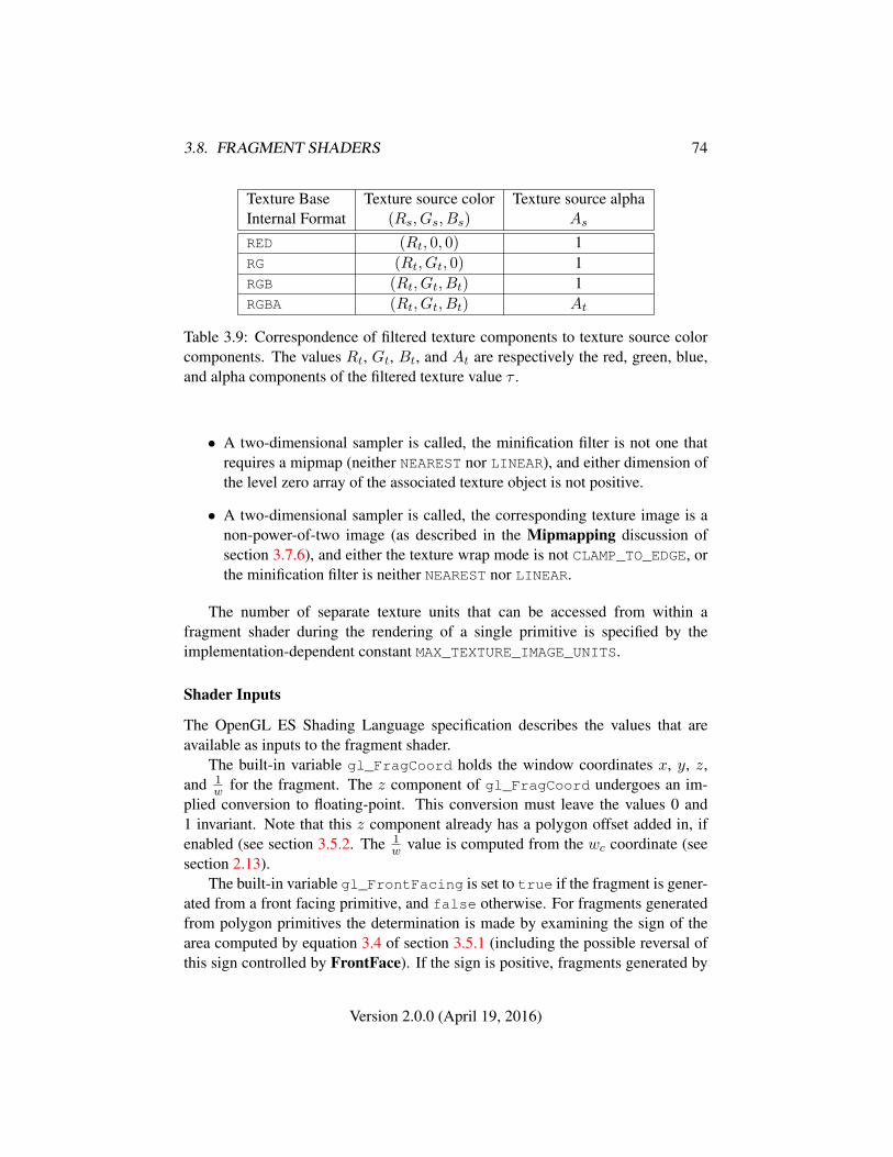
3.8. FRAGMENT SHADERS 74
Texture Base Texture source color Texture source alphaInternal Format (Rs, Gs, Bs) As
RED (Rt, 0, 0) 1RG (Rt, Gt, 0) 1RGB (Rt, Gt, Bt) 1RGBA (Rt, Gt, Bt) At
Table 3.9: Correspondence of filtered texture components to texture source colorcomponents. The values Rt, Gt, Bt, and At are respectively the red, green, blue,and alpha components of the filtered texture value τ .
• A two-dimensional sampler is called, the minification filter is not one thatrequires a mipmap (neither NEAREST nor LINEAR), and either dimension ofthe level zero array of the associated texture object is not positive.
• A two-dimensional sampler is called, the corresponding texture image is anon-power-of-two image (as described in the Mipmapping discussion ofsection 3.7.6), and either the texture wrap mode is not CLAMP_TO_EDGE, orthe minification filter is neither NEAREST nor LINEAR.
The number of separate texture units that can be accessed from within afragment shader during the rendering of a single primitive is specified by theimplementation-dependent constant MAX_TEXTURE_IMAGE_UNITS.
Shader Inputs
The OpenGL ES Shading Language specification describes the values that areavailable as inputs to the fragment shader.
The built-in variable gl_FragCoord holds the window coordinates x, y, z,and 1
w for the fragment. The z component of gl_FragCoord undergoes an im-plied conversion to floating-point. This conversion must leave the values 0 and1 invariant. Note that this z component already has a polygon offset added in, ifenabled (see section 3.5.2. The 1
w value is computed from the wc coordinate (seesection 2.13).
The built-in variable gl_FrontFacing is set to true if the fragment is gener-ated from a front facing primitive, and false otherwise. For fragments generatedfrom polygon primitives the determination is made by examining the sign of thearea computed by equation 3.4 of section 3.5.1 (including the possible reversal ofthis sign controlled by FrontFace). If the sign is positive, fragments generated by
Version 2.0.0 (April 19, 2016)

3.8. FRAGMENT SHADERS 75
the primitive are front facing; otherwise, they are back facing. All other fragmentsare considered front facing.
Shader Outputs
The OpenGL ES Shading Language specification describes the values that may beoutput by a fragment shader. These are gl_FragColor and gl_FragData[0]2. The final fragment color values or the final fragment data values written by afragment shader are clamped to the range [0, 1] and then converted to fixed-pointas described in section 2.1.2 for framebuffer color components.
Writing to gl_FragColor or gl_FragData[0] specifies the fragment color(color number zero) that will be used by subsequent stages of the pipeline. Anycolors, or color components, associated with a fragment that are not written bythe fragment shader are undefined. A fragment shader may not statically assignvalues to both gl_FragColor and gl_FragData[0]. In this case, a compile orlink error will result. A shader statically assigns a value to a variable if, after pre-processing, it contains a statement that would write to the variable, whether or notrun-time flow of control will cause that statement to be executed.
2gl_FragData is supported for compatibility with the desktop OpenGL Shading Language,but only a single fragment color output is allowed in the OpenGL ES Shading Language.
Version 2.0.0 (April 19, 2016)
Chapter 4
Per-Fragment Operations and theFramebuffer
The framebuffer consists of a set of pixels arranged as a two-dimensional array.The height and width of this array may vary from one GL implementation to an-other. For purposes of this discussion, each pixel in the framebuffer is simply a setof some number of bits. The number of bits per pixel may also vary depending onthe particular GL implementation or context.
Further there are two classes of framebuffers: the default framebuffer sup-plied by the window-system and application-created framebuffer objects. EveryOpenGL SC context has at most one default window-system-provided framebuffer.Applications can optionally create additional non-displayable framebuffer objects.For more information on application-created framebuffer objects, see section 4.4.
Corresponding bits from each pixel in the framebuffer are grouped together intoa bitplane; each bitplane contains a single bit from each pixel. These bitplanes aregrouped into several logical buffers. These are the color, depth, and stencil buffers.The color buffer actually consists of a number of buffers, and these color buffersserve related but slightly different purposes depending on whether they are boundto the default window-system-provided framebuffer or to an application-createdframebuffer object.
For the default window-system provided framebuffer, the color buffers consistof either or both of a front (single) buffer and a back buffer. Typically the contentsof the front buffer are displayed on a color monitor while the contents of the backbuffer are invisible. The color buffers must have the same number of bitplanes,although a context may not provide both types of buffers. Further, an implementa-
76
4.1. PER-FRAGMENT OPERATIONS 77
tion or context may not provide depth or stencil buffers 1. If no default framebufferis associated with the GL context, the framebuffer is incomplete except when aframebuffer object is bound. (see sections 4.4.1 and 4.4.5)
For application-created framebuffer objects, the color buffers are not visible,and consequently the names of the color buffers are not related to a display de-vice. The name of the color buffer of an application-created framebuffer ob-ject is COLOR_ATTACHMENT0. The names of the depth and stencil buffers areDEPTH_ATTACHMENT and STENCIL_ATTACHMENT. For more information aboutthe buffers of an application-created framebuffer object, see section 4.4.2. To beconsidered framebuffer complete (see section 4.4.5), all color buffers attached toan application-created framebuffer object must have the same number of bitplanes.Depth and stencil buffers may optionally be attached to application-created frame-buffers as well.
Color buffers consist of R, G, B, and, optionally, A unsigned integer values.The number of bitplanes in each of the color buffers, the depth buffer, and thestencil buffer is dependent on the currently bound framebuffer. For the defaultframebuffer, the number of bitplanes is fixed. For application-created framebufferobjects, however, the number of bitplanes in a given logical buffer may change ifthe state of the corresponding framebuffer attachment or attached image changes.
The initial state of all provided bitplanes is uninitialized.
4.1 Per-Fragment Operations
A fragment produced by rasterization with window coordinates of (xw, yw) mod-ifies the pixel in the framebuffer at that location based on a number of parametersand conditions. We describe these modifications and tests, diagrammed in Fig-ure 4.1, in the order in which they are performed.
4.1.1 Pixel Ownership Test
The first test is to determine if the pixel at location (xw, yw) in the framebufferis currently owned by the GL (more precisely, by this GL context). If it is not,the window system decides the fate of the incoming fragment. Possible results arethat the fragment is discarded or that some subset of the subsequent per-fragmentoperations are applied to the fragment. This test allows the window system tocontrol the GL’s behavior, for instance, when a GL window is obscured.
1However, an OpenGL SC implementation must support at least one config with a depth bit depthof 16 or higher and a stencil bit depth of 8 or higher
Version 2.0.0 (April 19, 2016)
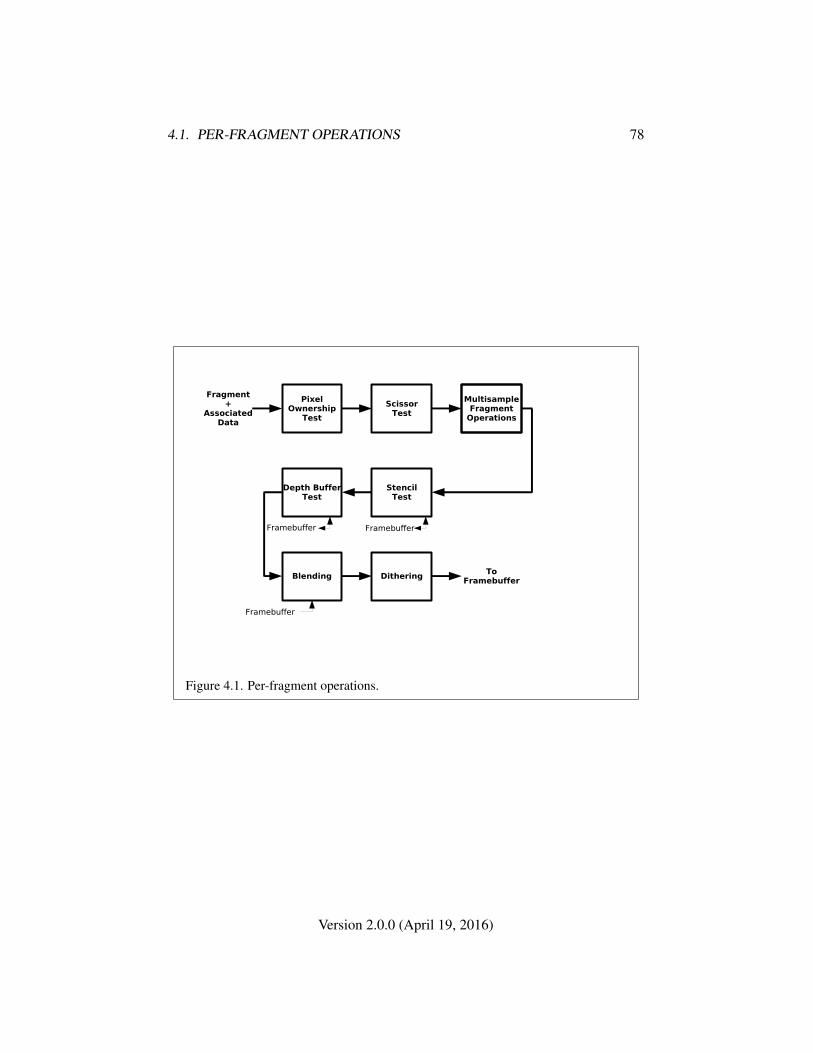
4.1. PER-FRAGMENT OPERATIONS 78
Depth BufferTest
ToFramebuffer
PixelOwnership
Test
ScissorTest
Fragment+
AssociatedData
StencilTest
Blending Dithering
MultisampleFragment
Operations
Framebuffer Framebuffer
Framebuffer
Figure 4.1. Per-fragment operations.
Version 2.0.0 (April 19, 2016)
4.1. PER-FRAGMENT OPERATIONS 79
While an application-created framebuffer object is bound to FRAMEBUFFER,the pixel ownership test always passes. The pixels of application-created frame-buffer objects are always owned by OpenGL SC , not the window system.Only while the window-system-provided framebuffer named zero is bound toFRAMEBUFFER does the window system control pixel ownership.
4.1.2 Scissor Test
The scissor test determines if (xw, yw) lies within the scissor rectangle defined byfour values. These values are set with
void Scissor( int left, int bottom, sizei width,sizei height );
If left ≤ xw < left + width and bottom ≤ yw < bottom + height , then thescissor test passes. Otherwise, the test fails and the fragment is discarded. The testis enabled or disabled using Enable or Disable using the constant SCISSOR_TEST.When disabled, it is as if the scissor test always passes. If either width or heightis less than zero, then the error INVALID_VALUE is generated. The state requiredconsists of four integer values and a bit indicating whether the test is enabled ordisabled. In the initial state left = bottom = 0; width and height are determinedby the size of the GL window. Initially, the scissor test is disabled. If the defaultframebuffer is bound but no default framebuffer is associated with the GL context(see chapter 4), then width and height are initially set to zero.
4.1.3 Multisample Fragment Operations
This step modifies fragment alpha and coverage values based on the valuesof SAMPLE_ALPHA_TO_COVERAGE, SAMPLE_COVERAGE, SAMPLE_COVERAGE_-VALUE, and SAMPLE_COVERAGE_INVERT. No changes to the fragment alpha orcoverage values are made at this step if the value of SAMPLE_BUFFERS is not one.
SAMPLE_ALPHA_TO_COVERAGE and SAMPLE_COVERAGE are enabled and dis-abled by calling Enable and Disable with cap specified as one of the two tokenvalues. Both values are queried by calling IsEnabled with cap set to the desiredtoken value. If SAMPLE_ALPHA_TO_COVERAGE is enabled, a temporary coveragevalue is generated where each bit is determined by the alpha value at the corre-sponding sample location. The temporary coverage value is then ANDed with thefragment coverage value. Otherwise the fragment coverage value is unchanged atthis point.
No specific algorithm is required for converting the sample alpha values to atemporary coverage value. It is intended that the number of 1’s in the temporary
Version 2.0.0 (April 19, 2016)
4.1. PER-FRAGMENT OPERATIONS 80
coverage be proportional to the set of alpha values for the fragment, with all 1’scorresponding to the maximum of all alpha values, and all 0’s corresponding toall alpha values being 0. It is also intended that the algorithm be pseudo-randomin nature, to avoid image artifacts due to regular coverage sample locations. Thealgorithm can and probably should be different at different pixel locations. If itdoes differ, it should be defined relative to window, not screen, coordinates, so thatrendering results are invariant with respect to window position.
Finally, if SAMPLE_COVERAGE is enabled, the fragment coverage is ANDedwith another temporary coverage. This temporary coverage is generated in thesame manner as the one described above, but as a function of the value ofSAMPLE_COVERAGE_VALUE. The function need not be identical, but it must havethe same properties of proportionality and invariance. If SAMPLE_COVERAGE_-INVERT is TRUE, the temporary coverage is inverted (all bit values are inverted)before it is ANDed with the fragment coverage.
The values of SAMPLE_COVERAGE_VALUE and SAMPLE_COVERAGE_INVERT
are specified by calling
void SampleCoverage( float value, boolean invert );
with value set to the desired coverage value, and invert set to TRUE or FALSE.value is clamped to [0,1] before being stored as SAMPLE_COVERAGE_VALUE.SAMPLE_COVERAGE_VALUE is queried by calling GetFloatv with pname set toSAMPLE_COVERAGE_VALUE. SAMPLE_COVERAGE_INVERT is queried by callingGetBooleanv with pname set to SAMPLE_COVERAGE_INVERT.
4.1.4 Stencil Test
The stencil test conditionally discards a fragment based on the outcome of a com-parison between the value in the stencil buffer at location (xw, yw) and a referencevalue. The test is enabled or disabled with the Enable and Disable commands,using the symbolic constant STENCIL_TEST. When disabled, the stencil test andassociated modifications are not made, and the fragment is always passed.
The stencil test is controlled with
void StencilFunc( enum func, int ref, uint mask );void StencilFuncSeparate( enum face, enum func, int ref,
uint mask );void StencilOp( enum sfail, enum dpfail, enum dppass );void StencilOpSeparate( enum face, enum sfail, enum dpfail,
enum dppass );
Version 2.0.0 (April 19, 2016)
4.1. PER-FRAGMENT OPERATIONS 81
There are two sets of stencil-related state, the front stencil state set and the backstencil state set. Stencil tests and writes use the front set of stencil state when pro-cessing fragments rasterized from non-polygon primitives (points, lines, bitmaps,image rectangles) and front-facing polygon primitives while the back set of stencilstate is used when processing fragments rasterized from back-facing polygon prim-itives. For the purposes of stencil testing, a primitive is still considered a polygoneven if the polygon is to be rasterized as points or lines due to the current poly-gon mode. Whether a polygon is front- or back-facing is determined in the samemanner used for face culling (see section 3.5.1).
StencilFuncSeparate and StencilOpSeparate take a face argument which canbe FRONT, BACK, or FRONT_AND_BACK and indicates which set of state is affected.StencilFunc and StencilOp set front and back stencil state to identical values.
StencilFunc and StencilFuncSeparate take three arguments that controlwhether the stencil test passes or fails. ref is an integer reference value that is usedin the unsigned stencil comparison. Stencil comparison operations and queries ofref clamp its value to the range [0, 2s − 1], where s is the number of bits in thestencil buffer attached to the framebuffer. The s least significant bits of mask arebitwise ANDed with both the reference and the stored stencil value, and the result-ing masked values are those that participate in the comparison controlled by func.func is a symbolic constant that determines the stencil comparison function; theeight symbolic constants are NEVER, ALWAYS, LESS, LEQUAL, EQUAL, GEQUAL,GREATER, or NOTEQUAL. Accordingly, the stencil test passes never, always, andif the masked reference value is less than, less than or equal to, equal to, greaterthan or equal to, greater than, or not equal to the masked stored value in the stencilbuffer.
StencilOp and StencilOpSeparate take three arguments that indicate whathappens to the stored stencil value if this or certain subsequent tests fail or pass.sfail indicates what action is taken if the stencil test fails. The symbolic constantsare KEEP, ZERO, REPLACE, INCR, DECR, INVERT, INCR_WRAP, and DECR_WRAP.These correspond to keeping the current value, setting to zero, replacing with thereference value, incrementing with saturation, decrementing with saturation, bit-wise inverting it, incrementing without saturation, and decrementing without satu-ration.
For purposes of increment and decrement, the stencil bits are considered as anunsigned integer. Incrementing or decrementing with saturation clamps the stencilvalue at 0 and the maximum representable value. Incrementing or decrementingwithout saturation will wrap such that incrementing the maximum representablevalue results in 0, and decrementing 0 results in the maximum representable value.
The same symbolic values are given to indicate the stencil action if the depthbuffer test (see section 4.1.5) fails (dpfail), or if it passes (dppass).
Version 2.0.0 (April 19, 2016)
4.1. PER-FRAGMENT OPERATIONS 82
If the stencil test fails, the incoming fragment is discarded. The state requiredconsists of the most recent values passed to StencilFunc or StencilFuncSeparateand to StencilOp or StencilOpSeparate, and a bit indicating whether stencil test-ing is enabled or disabled. In the initial state, stenciling is disabled, the front andback stencil reference value are both zero, the front and back stencil comparisonfunctions are both ALWAYS, and the front and back stencil mask are both all ones.Initially, all three front and back stencil operations are KEEP.
If there is no stencil buffer, no stencil modification can occur, and it is as if thestencil tests always pass, regardless of any calls to StencilFunc.
4.1.5 Depth Buffer Test
The depth buffer test discards the incoming fragment if a depth comparison fails.The comparison is enabled or disabled with the generic Enable and Disable com-mands using the symbolic constant DEPTH_TEST. When disabled, the depth com-parison and subsequent possible updates to the depth buffer value are bypassed andthe fragment is passed to the next operation. The stencil value, however, is modi-fied as indicated below as if the depth buffer test passed. If enabled, the comparisontakes place and the depth buffer and stencil value may subsequently be modified.
The comparison is specified with
void DepthFunc( enum func );
This command takes a single symbolic constant: one of NEVER, ALWAYS, LESS,LEQUAL, EQUAL, GREATER, GEQUAL, NOTEQUAL. Accordingly, the depth buffertest passes never, always, if the incoming fragment’s zw value is less than, lessthan or equal to, equal to, greater than, greater than or equal to, or not equal tothe depth value stored at the location given by the incoming fragment’s (xw, yw)coordinates.
If the depth buffer test fails, the incoming fragment is discarded. The stencilvalue at the fragment’s (xw, yw) coordinates is updated according to the functioncurrently in effect for depth buffer test failure. Otherwise, the fragment continuesto the next operation and the value of the depth buffer at the fragment’s (xw, yw)location is set to the fragment’s zw value. In this case the stencil value is updatedaccording to the function currently in effect for depth buffer test success.
The necessary state is an eight-valued integer and a single bit indicatingwhether depth buffering is enabled or disabled. In the initial state the functionis LESS and the test is disabled.
If there is no depth buffer, it is as if the depth buffer test always passes.
Version 2.0.0 (April 19, 2016)

4.1. PER-FRAGMENT OPERATIONS 83
4.1.6 Blending
Blending combines the incoming source fragment’s R, G, B, and A values withthe destination R, G, B, and A values stored in the framebuffer at the fragment’s(xw, yw) location.
Source and destination values are combined according to the blend equation,quadruplets of source and destination weighting factors determined by the blendfunctions, and a constant blend color to obtain a new set of R, G, B, and A val-ues, as described below. Each of these floating-point values is clamped to [0, 1]and converted back to a fixed-point value in the manner described in section 2.1.2for framebuffer color components. The resulting four values are sent to the nextoperation.
Blending is dependent on the incoming fragment’s alpha value and that of thecorresponding currently stored pixel. Blending is enabled or disabled using Enableor Disable with the symbolic constant BLEND. If it is disabled, proceed to the nextoperation.
Blend Equation
Blending is controlled by the blend equations, defined by the commands
void BlendEquation( enum mode );void BlendEquationSeparate( enum modeRGB,
enum modeAlpha );
BlendEquationSeparate argument modeRGB determines the RGB blend functionwhile modeAlpha determines the alpha blend equation. BlendEquation argumentmode determines both the RGB and alpha blend equations. modeRGB and mod-eAlpha must each be one of FUNC_ADD, FUNC_SUBTRACT, or FUNC_REVERSE_-SUBTRACT.
Destination (framebuffer) components are taken to be fixed-point values rep-resented according to the scheme described in section 2.1.2 for framebuffer colorcomponents, as are source (fragment) components. Constant color components aretaken to be floating-point values.
Prior to blending, each fixed-point color component undergoes an implied con-version to floating-point. This conversion must leave the values 0 and 1 invariant.Blending components are treated as if carried out in floating-point.
Table 4.1 provides the corresponding per-component blend equations for eachmode, whether acting on RGB components for modeRGB or the alpha componentfor modeAlpha.
Version 2.0.0 (April 19, 2016)
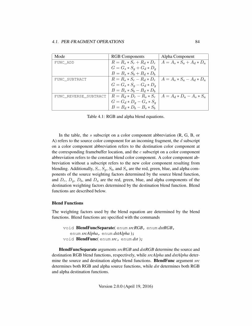
4.1. PER-FRAGMENT OPERATIONS 84
Mode RGB Components Alpha ComponentFUNC_ADD R = Rs ∗ Sr +Rd ∗Dr A = As ∗ Sa +Ad ∗Da
G = Gs ∗ Sg +Gd ∗Dg
B = Bs ∗ Sb +Bd ∗Db
FUNC_SUBTRACT R = Rs ∗ Sr −Rd ∗Dr A = As ∗ Sa −Ad ∗Da
G = Gs ∗ Sg −Gd ∗Dg
B = Bs ∗ Sb −Bd ∗Db
FUNC_REVERSE_SUBTRACT R = Rd ∗Dr −Rs ∗ Sr A = Ad ∗Da −As ∗ SaG = Gd ∗Dg −Gs ∗ SgB = Bd ∗Db −Bs ∗ Sb
Table 4.1: RGB and alpha blend equations.
In the table, the s subscript on a color component abbreviation (R, G, B, orA) refers to the source color component for an incoming fragment, the d subscripton a color component abbreviation refers to the destination color component atthe corresponding framebuffer location, and the c subscript on a color componentabbreviation refers to the constant blend color component. A color component ab-breviation without a subscript refers to the new color component resulting fromblending. Additionally, Sr, Sg, Sb, and Sa are the red, green, blue, and alpha com-ponents of the source weighting factors determined by the source blend function,and Dr, Dg, Db, and Da are the red, green, blue, and alpha components of thedestination weighting factors determined by the destination blend function. Blendfunctions are described below.
Blend Functions
The weighting factors used by the blend equation are determined by the blendfunctions. Blend functions are specified with the commands
void BlendFuncSeparate( enum srcRGB, enum dstRGB,enum srcAlpha, enum dstAlpha );
void BlendFunc( enum src, enum dst );
BlendFuncSeparate arguments srcRGB and dstRGB determine the source anddestination RGB blend functions, respectively, while srcAlpha and dstAlpha deter-mine the source and destination alpha blend functions. BlendFunc argument srcdetermines both RGB and alpha source functions, while dst determines both RGBand alpha destination functions.
Version 2.0.0 (April 19, 2016)
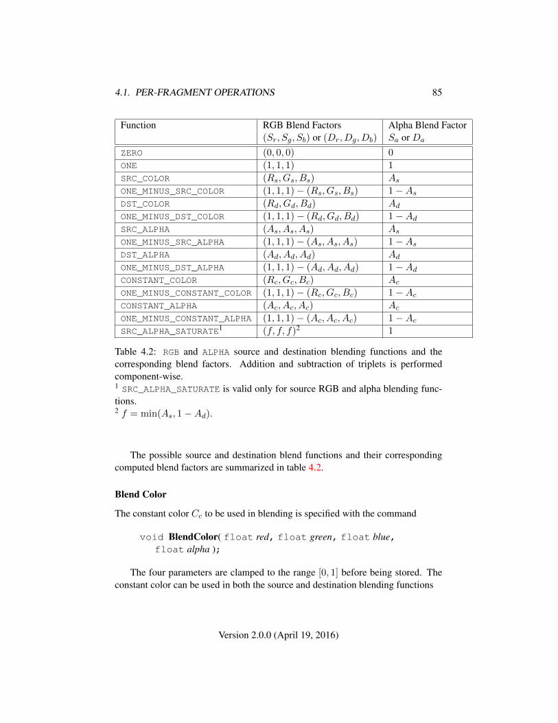
4.1. PER-FRAGMENT OPERATIONS 85
Function RGB Blend Factors Alpha Blend Factor(Sr, Sg, Sb) or (Dr, Dg, Db) Sa or Da
ZERO (0, 0, 0) 0
ONE (1, 1, 1) 1
SRC_COLOR (Rs, Gs, Bs) As
ONE_MINUS_SRC_COLOR (1, 1, 1)− (Rs, Gs, Bs) 1−As
DST_COLOR (Rd, Gd, Bd) Ad
ONE_MINUS_DST_COLOR (1, 1, 1)− (Rd, Gd, Bd) 1−Ad
SRC_ALPHA (As, As, As) As
ONE_MINUS_SRC_ALPHA (1, 1, 1)− (As, As, As) 1−As
DST_ALPHA (Ad, Ad, Ad) Ad
ONE_MINUS_DST_ALPHA (1, 1, 1)− (Ad, Ad, Ad) 1−Ad
CONSTANT_COLOR (Rc, Gc, Bc) Ac
ONE_MINUS_CONSTANT_COLOR (1, 1, 1)− (Rc, Gc, Bc) 1−Ac
CONSTANT_ALPHA (Ac, Ac, Ac) Ac
ONE_MINUS_CONSTANT_ALPHA (1, 1, 1)− (Ac, Ac, Ac) 1−Ac
SRC_ALPHA_SATURATE1 (f, f, f)2 1
Table 4.2: RGB and ALPHA source and destination blending functions and thecorresponding blend factors. Addition and subtraction of triplets is performedcomponent-wise.1 SRC_ALPHA_SATURATE is valid only for source RGB and alpha blending func-tions.2 f = min(As, 1−Ad).
The possible source and destination blend functions and their correspondingcomputed blend factors are summarized in table 4.2.
Blend Color
The constant color Cc to be used in blending is specified with the command
void BlendColor( float red, float green, float blue,float alpha );
The four parameters are clamped to the range [0, 1] before being stored. Theconstant color can be used in both the source and destination blending functions
Version 2.0.0 (April 19, 2016)
4.1. PER-FRAGMENT OPERATIONS 86
Blending State
The state required for blending is two integers for the RGB and alpha blend equa-tions, four integers indicating the source and destination RGB and alpha blendingfunctions, four floating-point values to store the RGBA constant blend color, and abit indicating whether blending is enabled or disabled. The initial blend equationsfor RGB and alpha are both FUNC_ADD. The initial blending functions are ONE forthe source RGB and alpha functions and ZERO for the destination RGB and alphafunctions. The initial constant blend color is (R,G,B,A) = (0, 0, 0, 0). Initially,blending is disabled.
Blending occurs once for each color buffer currently enabled for writing (sec-tion 4.2.1) using each buffer’s color for Cd. If a color buffer has no A value, thenAd is taken to be 1.
4.1.7 Dithering
Dithering selects between two color values. Consider the value of any of the colorcomponents as a fixed-point value with m bits to the left of the binary point, wherem is the number of bits allocated to that component in the framebuffer; call eachsuch value c. For each c, dithering selects a value c1 such that c1 ∈ {max{0, dce−1}, dce} (after this selection, treat c1 as a fixed point value in [0,1] with m bits).This selection may depend on the xw and yw coordinates of the pixel. c must notbe larger than the maximum value representable in the framebuffer for either thecomponent or the index, as appropriate.
Many dithering algorithms are possible, but a dithered value produced by anyalgorithm must depend only the incoming value and the fragment’s x and y windowcoordinates. If dithering is disabled, then each color component is truncated to afixed-point value with as many bits as there are in the corresponding component inthe framebuffer.
Dithering is enabled with Enable and disabled with Disable using the symbolicconstant DITHER. The state required is thus a single bit. Initially, dithering isenabled.
4.1.8 Additional Multisample Fragment Operations
If the value of SAMPLE_BUFFERS is one, the stencil test, depth test, blending, anddithering operations are performed for each pixel sample, rather than just once foreach fragment. Failure of the stencil or depth test results in termination of theprocessing of that sample, rather than discarding of the fragment. All operationsare performed on the color, depth, and stencil values stored in the multisample
Version 2.0.0 (April 19, 2016)

4.2. WHOLE FRAMEBUFFER OPERATIONS 87
buffer (to be described in a following section). The contents of the color buffer arenot modified at this point.
Stencil, depth, blending, and dithering operations are performed for a pixelsample only if that sample’s fragment coverage bit is a value of 1. If the corre-sponding coverage bit is 0, no operations are performed for that sample.
If the value of SAMPLE_BUFFERS is one, the fragment may be treated exactlyas described above, with optimization possible because the fragment coverage mustbe set to full coverage. Further optimization is allowed, however. An implementa-tion may choose to identify a centermost sample, and to perform stencil and depthtests on only that sample. Regardless of the outcome of the stencil test, all multi-sample buffer stencil sample values are set to the appropriate new stencil value. Ifthe depth test passes, all multisample buffer depth sample values are set to the depthof the fragment’s centermost sample’s depth value, and all multisample buffer colorsample values are set to the color value of the incoming fragment. Otherwise, nochange is made to any multisample buffer color or depth value.
After all operations have been completed on the multisample buffer, the colorsample values are combined to produce a single color value, and that value is writ-ten into the color buffer selected for writing (see section 4.2.1). An implementa-tion may defer the writing of the color buffer until a later time, but the state of theframebuffer must behave as if the color buffer was updated as each fragment wasprocessed. The method of combination is not specified, though a simple averagecomputed independently for each color component is recommended.
4.2 Whole Framebuffer Operations
The preceding sections described the operations that occur as individual fragmentsare sent to the framebuffer. This section describes operations that control or affectthe whole framebuffer.
4.2.1 Selecting a Buffer for Writing
Color values are written into the front buffer for single buffered contexts, or intothe back buffer for back buffered contexts. The type of context is determined whencreating a GL context.
4.2.2 Fine Control of Buffer Updates
Four commands are used to mask the writing of bits to each of the logical frame-buffers after all per-fragment operations have been performed. The command
Version 2.0.0 (April 19, 2016)
4.2. WHOLE FRAMEBUFFER OPERATIONS 88
void ColorMask( boolean r, boolean g, boolean b,boolean a );
controls the writing of R, G, B and A values to the color buffer. r, g, b, and aindicate whether R, G, B, or A values, respectively, are written or not (a value ofTRUE means that the corresponding value is written). In the initial state, all colorvalues are enabled for writing.
The depth buffer can be enabled or disabled for writing zw values using
void DepthMask( boolean mask );
If mask is non-zero, the depth buffer is enabled for writing; otherwise, it is disabled.In the initial state, the depth buffer is enabled for writing.
The commands
void StencilMask( uint mask );void StencilMaskSeparate( enum face, uint mask );
control the writing of particular bits into the stencil planes.The least significant s bits of mask , where s is the number of bits in the stencil
buffer, specify a mask. Where a 1 appears in this mask, the corresponding bit inthe stencil buffer is written; where a 0 appears, the bit is not written.
The face parameter of StencilMaskSeparate can be FRONT, BACK, orFRONT_AND_BACK and indicates whether the front or back stencil mask state isaffected. StencilMask sets both front and back stencil mask state to identical val-ues.
Fragments generated by front facing primitives use the front mask and frag-ments generated by back facing primitives use the back mask (see section 4.1.4).The clear operation always uses the front stencil write mask when clearing thestencil buffer.
The state required for the various masking operations is three integers and abit: an integer for color indices, an integer for the front and back stencil values,and a bit for depth values. A set of four bits is also required indicating which colorcomponents of an RGBA value should be written. In the initial state, the integermasks are all ones, as are the bits controlling depth value and RGBA componentwriting.
Fine Control of Multisample Buffer Update s
When the value of SAMPLE_BUFFERS is one, ColorMask, DepthMask, and Sten-cilMask control the modification of values in the multisample buffer. The color
Version 2.0.0 (April 19, 2016)
4.2. WHOLE FRAMEBUFFER OPERATIONS 89
mask has no effect on modifications to the color buffer. If the color mask is entirelydisabled, the color sample values must still be combined (as described above) andthe result used to replace values of the color buffer.
4.2.3 Clearing the Buffers
The GL provides a means for setting portions of every pixel in a particular bufferto the same value. The argument to
void Clear( bitfield buf );
is the bitwise OR of a number of values indicating which buffers are to be cleared.The values are COLOR_BUFFER_BIT, DEPTH_BUFFER_BIT, and STENCIL_-
BUFFER_BIT, indicating the color buffer, the depth buffer, and the stencil buffer,respectively. The value to which each buffer is cleared depends on the setting of theclear value for that buffer. If the mask is not a bitwise OR of the specified values,then the error INVALID_VALUE is generated.
void ClearColor( float r, float g, float b, float a );
sets the clear value for the color buffer. Each of the specified components isclamped to [0, 1] and converted to fixed-point as described in section 2.1.2 forframebuffer color components.
void ClearDepthf( float d );
takes a value that is clamped to the range [0, 1] and converted to fixed-point accord-ing to the rules for a window z value given in section 2.13.1. Similarly,
void ClearStencil( int s );
takes a single integer argument that is the value to which to clear the stencil buffer.s is masked to the number of bitplanes in the stencil buffer.
When Clear is called, the only per-fragment operations that are applied (ifenabled) are the pixel ownership test, the scissor test, and dithering. The maskingoperations described in the last section (4.2.2) are also effective. If a buffer is notpresent, then a Clear directed at that buffer has no effect.
The state required for clearing is a clear value for each of the color buffer,the depth buffer, and the stencil buffer. Initially, the RGBA color clear value is(0,0,0,0), the stencil buffer clear value is 0, and the depth buffer clear value is 1.0.
Version 2.0.0 (April 19, 2016)
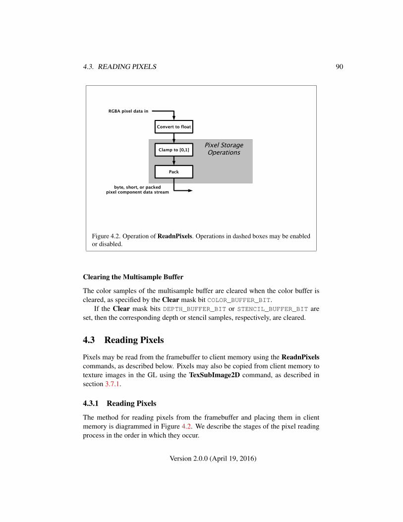
4.3. READING PIXELS 90
byte, short, or packedpixel component data stream
Clamp to [0,1]
Pack
Convert to float
RGBA pixel data in
Pixel StorageOperations
Figure 4.2. Operation of ReadnPixels. Operations in dashed boxes may be enabledor disabled.
Clearing the Multisample Buffer
The color samples of the multisample buffer are cleared when the color buffer iscleared, as specified by the Clear mask bit COLOR_BUFFER_BIT.
If the Clear mask bits DEPTH_BUFFER_BIT or STENCIL_BUFFER_BIT areset, then the corresponding depth or stencil samples, respectively, are cleared.
4.3 Reading Pixels
Pixels may be read from the framebuffer to client memory using the ReadnPixelscommands, as described below. Pixels may also be copied from client memory totexture images in the GL using the TexSubImage2D command, as described insection 3.7.1.
4.3.1 Reading Pixels
The method for reading pixels from the framebuffer and placing them in clientmemory is diagrammed in Figure 4.2. We describe the stages of the pixel readingprocess in the order in which they occur.
Version 2.0.0 (April 19, 2016)
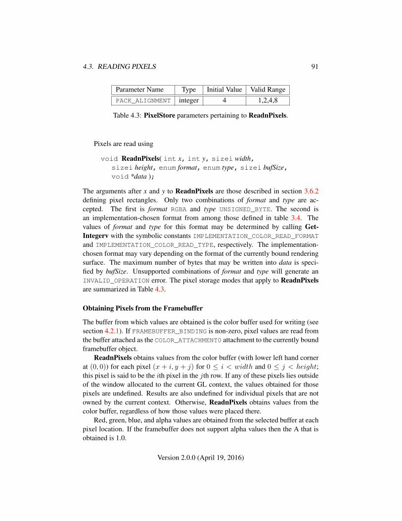
4.3. READING PIXELS 91
Parameter Name Type Initial Value Valid RangePACK_ALIGNMENT integer 4 1,2,4,8
Table 4.3: PixelStore parameters pertaining to ReadnPixels.
Pixels are read using
void ReadnPixels( int x, int y, sizei width,sizei height, enum format, enum type, sizei bufSize,void *data );
The arguments after x and y to ReadnPixels are those described in section 3.6.2defining pixel rectangles. Only two combinations of format and type are ac-cepted. The first is format RGBA and type UNSIGNED_BYTE. The second isan implementation-chosen format from among those defined in table 3.4. Thevalues of format and type for this format may be determined by calling Get-Integerv with the symbolic constants IMPLEMENTATION_COLOR_READ_FORMATand IMPLEMENTATION_COLOR_READ_TYPE, respectively. The implementation-chosen format may vary depending on the format of the currently bound renderingsurface. The maximum number of bytes that may be written into data is speci-fied by bufSize. Unsupported combinations of format and type will generate anINVALID_OPERATION error. The pixel storage modes that apply to ReadnPixelsare summarized in Table 4.3.
Obtaining Pixels from the Framebuffer
The buffer from which values are obtained is the color buffer used for writing (seesection 4.2.1). If FRAMEBUFFER_BINDING is non-zero, pixel values are read fromthe buffer attached as the COLOR_ATTACHMENT0 attachment to the currently boundframebuffer object.
ReadnPixels obtains values from the color buffer (with lower left hand cornerat (0, 0)) for each pixel (x + i, y + j) for 0 ≤ i < width and 0 ≤ j < height;this pixel is said to be the ith pixel in the jth row. If any of these pixels lies outsideof the window allocated to the current GL context, the values obtained for thosepixels are undefined. Results are also undefined for individual pixels that are notowned by the current context. Otherwise, ReadnPixels obtains values from thecolor buffer, regardless of how those values were placed there.
Red, green, blue, and alpha values are obtained from the selected buffer at eachpixel location. If the framebuffer does not support alpha values then the A that isobtained is 1.0.
Version 2.0.0 (April 19, 2016)
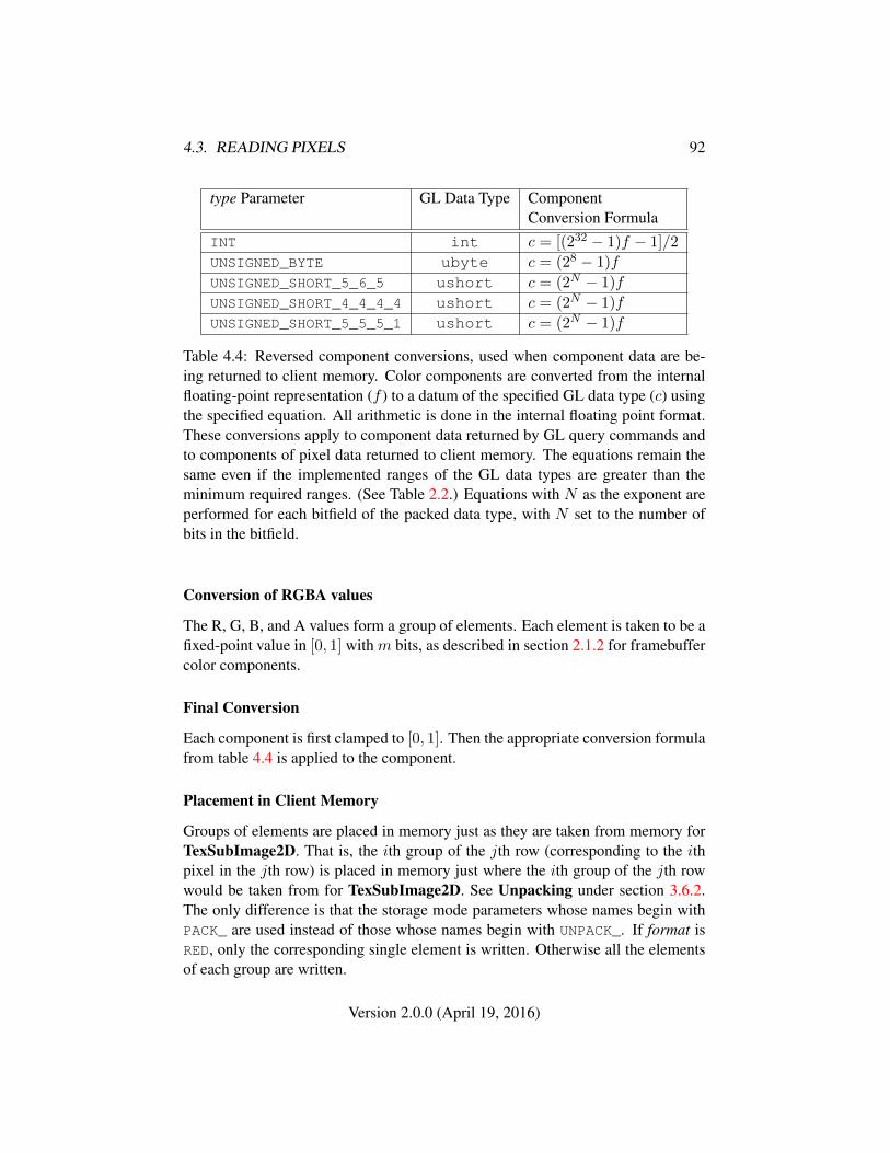
4.3. READING PIXELS 92
type Parameter GL Data Type ComponentConversion Formula
INT int c = [(232 − 1)f − 1]/2
UNSIGNED_BYTE ubyte c = (28 − 1)f
UNSIGNED_SHORT_5_6_5 ushort c = (2N − 1)f
UNSIGNED_SHORT_4_4_4_4 ushort c = (2N − 1)f
UNSIGNED_SHORT_5_5_5_1 ushort c = (2N − 1)f
Table 4.4: Reversed component conversions, used when component data are be-ing returned to client memory. Color components are converted from the internalfloating-point representation (f ) to a datum of the specified GL data type (c) usingthe specified equation. All arithmetic is done in the internal floating point format.These conversions apply to component data returned by GL query commands andto components of pixel data returned to client memory. The equations remain thesame even if the implemented ranges of the GL data types are greater than theminimum required ranges. (See Table 2.2.) Equations with N as the exponent areperformed for each bitfield of the packed data type, with N set to the number ofbits in the bitfield.
Conversion of RGBA values
The R, G, B, and A values form a group of elements. Each element is taken to be afixed-point value in [0, 1] with m bits, as described in section 2.1.2 for framebuffercolor components.
Final Conversion
Each component is first clamped to [0, 1]. Then the appropriate conversion formulafrom table 4.4 is applied to the component.
Placement in Client Memory
Groups of elements are placed in memory just as they are taken from memory forTexSubImage2D. That is, the ith group of the jth row (corresponding to the ithpixel in the jth row) is placed in memory just where the ith group of the jth rowwould be taken from for TexSubImage2D. See Unpacking under section 3.6.2.The only difference is that the storage mode parameters whose names begin withPACK_ are used instead of those whose names begin with UNPACK_. If format isRED, only the corresponding single element is written. Otherwise all the elementsof each group are written.
Version 2.0.0 (April 19, 2016)
4.4. FRAMEBUFFER OBJECTS 93
4.3.2 Pixel Draw/Read State
The state required for pixel operations consists of the parameters that are set withPixelStore. This state has been summarized in tables 3.1. State set with PixelStoreis GL client state.
4.4 Framebuffer Objects
As described in chapters 1 and 2, OpenGL SC renders into (and reads values from)a framebuffer. OpenGL SC defines two classes of framebuffers: window-system-provided framebuffers and application-created framebuffers.
By default, OpenGL SC uses the window-system-provided framebuffer. Thestorage, dimensions, allocation, and format of the images attached to this frame-buffer are managed entirely by the window-system. Consequently, the state of thewindow-system-provided framebuffer, including its images, cannot be changed byOpenGL SC , nor can the window-system-provided framebuffer itself, or its im-ages, be deleted by OpenGL SC .
The routines described in the following sections, however, can be used to cre-ate, destroy, and modify the state and attachments of application-created frame-buffer objects.
Application-created framebuffer objects encapsulate the state of a framebufferin a similar manner to the way texture objects encapsulate the state of a texture. Inparticular, a framebuffer object encapsulates state necessary to describe a collectionof color, depth, and stencil logical buffers. For each logical buffer, a framebuffer-attachable image can be attached to the framebuffer to store the rendered outputfor that logical buffer. Examples of framebuffer-attachable images include textureimages and renderbuffer images.
By allowing the images of a renderbuffer to be attached to a framebuffer,OpenGL SC provides a mechanism to support off-screen rendering. Further, byallowing the images of a texture to be attached to a framebuffer, OpenGL SC pro-vides a mechanism to support render to texture.
4.4.1 Binding and Managing Framebuffer Objects
The operations described in chapter 4 affect the images attached to the framebufferobject bound to the target FRAMEBUFFER. By default, the framebuffer bound tothe target FRAMEBUFFER is zero, specifying the default implementation-dependentframebuffer provided by the windowing system. When the framebuffer bound totarget FRAMEBUFFER is not zero, but instead names an application-created frame-
Version 2.0.0 (April 19, 2016)
4.4. FRAMEBUFFER OBJECTS 94
buffer object, then the operations described in chapter 4 affect the application-created framebuffer object rather than the default framebuffer.
The namespace for framebuffer objects is the unsigned integers, with zero re-served by OpenGL SC to refer to the default framebuffer. A framebuffer objectis created by binding a framebuffer object name obtained by calling GenFrame-buffers to the target FRAMEBUFFER. The binding is effected by calling
void BindFramebuffer( enum target, uint framebuffer );
with target set to FRAMEBUFFER and framebuffer set to the framebuffer objectname obtained from GenFramebuffers. The resulting framebuffer object is a newstate vector. There is one color attachment point, plus one each for the depth andstencil attachment points. Calling BindFramebuffer with a framebuffer objectname not obtained by GenFramebuffers will result in a INVALID_OPERATION
error. Framebuffer objects cannot be deleted.BindFramebuffer may also be used to bind an existing framebuffer ob-
ject to target. If the bind is successful no change is made to the state of thebound framebuffer object and any previous binding to target is broken. The cur-rent FRAMEBUFFER binding can be queried using GetIntegerv(FRAMEBUFFER_-BINDING).
While a framebuffer object is bound to the target FRAMEBUFFER, OpenGL SCoperations on the target to which it is bound affect the images attached to the boundframebuffer object, and queries of the target to which it is bound return state fromthe bound object. In particular, queries of the values specified in table 6.20 (Imple-mentation Dependent Pixel Depths) are derived from the currently bound frame-buffer object. The framebuffer object bound to the target FRAMEBUFFER is usedas the destination of fragment operations and as the source of pixel reads such asReadnPixels.
In the initial state, the reserved name zero is bound to the target FRAMEBUFFER.There is no application created framebuffer object corresponding to the name zero.Instead, the name zero refers to the window-system-provided framebuffer, if thereis one. All queries and operations on the framebuffer while the name zero is boundto the target FRAMEBUFFER operate on this default framebuffer. On some imple-mentations, the properties of the default window system provided framebuffer canchange over time (e.g., in response to window system events such as attaching thecontext to a new window system drawable.)
Application created framebuffer objects (i.e., those with a non-zero name) dif-fer from the default window-system-provided framebuffer in a few important ways.First and foremost, unlike the window-system-provided framebuffer, applicationcreated framebuffers have modifiable attachment points for each logical buffer in
Version 2.0.0 (April 19, 2016)
4.4. FRAMEBUFFER OBJECTS 95
the framebuffer. Framebuffer attachable images can be attached to and detachedfrom these attachment points. Also, the size and format of the images attachedto application created framebuffers are controlled entirely within the OpenGL SCinterface, and are not affected by window-system events, such as pixel format se-lection, window resizes, and display mode changes.
Additionally, when rendering to or reading from an application created frame-buffer object,
• The pixel ownership test always succeeds. In other words, application-created framebuffer objects own all of their pixels.
• There are no visible color buffer bitplanes. This means there is no colorbuffer corresponding to the back, or front color bitplanes.
• The only color buffer bitplanes are the ones defined by the framebuffer at-tachment point named COLOR_ATTACHMENT0.
• The only depth buffer bitplanes are the ones defined by the framebuffer at-tachment point DEPTH_ATTACHMENT.
• The only stencil buffer bitplanes are the ones defined by the framebufferattachment point STENCIL_ATTACHMENT.
• There is no multisample buffer, so the value of the implementation-dependent state variables SAMPLES and SAMPLE_BUFFERS are both 0.
The command
void GenFramebuffers( sizei n, uint *framebuffers );
returns n previously unused framebuffer object names in framebuffers. Thesenames are marked as used, for the purposes of GenFramebuffers only, but theyacquire state and type only when they are first bound, just as if they were unused.
4.4.2 Attaching Images to Framebuffer Objects
Framebuffer-attachable images may be attached to, and detached from,application-created framebuffer objects. In contrast, the image attachments of thewindow-system-provided framebuffer may not be changed by OpenGL SC .
A single framebuffer-attachable image may be attached to multiple application-created framebuffer objects, potentially avoiding some data copies, and possiblydecreasing memory consumption.
Version 2.0.0 (April 19, 2016)
4.4. FRAMEBUFFER OBJECTS 96
For each logical buffer, the framebuffer object stores a set of state which definesthe logical buffer’s attachment point. The attachment point state contains enoughinformation to identify the single image attached to the attachment point, or toindicate that no image is attached. The per-logical buffer attachment point state islisted in table 6.23.
There are two types of framebuffer-attachable images: the image of a render-buffer object, and an image of a texture object.
4.4.3 Renderbuffer Objects
A renderbuffer is a data storage object containing a single image of a renderableinternal format. OpenGL SC provides the methods described below to allocate arenderbuffer’s image, and to attach a renderbuffer’s image to a framebuffer object.
The name space for renderbuffer objects is the unsigned integers, with zero re-served for OpenGL SC . A renderbuffer object is created by binding a renderbufferobject name obtained by calling GenRenderbuffers to RENDERBUFFER. The bind-ing is effected by calling
void BindRenderbuffer( enum target, uint renderbuffer );
with target set to RENDERBUFFER and renderbuffer set to the renderbuffer objectname obtained from GenRenderBuffers. If renderbuffer is not zero, then theresulting renderbuffer object is a new state vector, initialized with a zero-sizedmemory buffer, and comprising the state values listed in table 6.22. Any previousbinding to target is broken. Calling BindRenderbuffer with a renderbuffer objectname not obtained by GenRenderbuffers will result in a INVALID_OPERATIONerror. Renderbuffer objects cannot be deleted.
BindRenderbuffer may also be used to bind an existing renderbuffer object.If the bind is successful, no change is made to the state of the newly bound render-buffer object, and any previous binding to target is broken.
While a renderbuffer object is bound, OpenGL SC operations on the target towhich it is bound affect the bound renderbuffer object, and queries of the target towhich a renderbuffer object is bound return state from the bound object.
The name zero is reserved. A renderbuffer object cannot be created with thename zero. If renderbuffer is zero, then any previous binding to target is brokenand the target binding is restored to the initial state.
In the initial state, the reserved name zero is bound to RENDERBUFFER. There isno renderbuffer object corresponding to the name zero, so client attempts to modifyor query renderbuffer state for the target RENDERBUFFER while zero is bound willgenerate errors.
Version 2.0.0 (April 19, 2016)
4.4. FRAMEBUFFER OBJECTS 97
Using GetIntegerv, the current RENDERBUFFER binding can be queried asRENDERBUFFER_BINDING.
The command
void GenRenderbuffers( sizei n, uint *renderbuffers );
returns n previously unused renderbuffer object names in renderbuffers. Thesenames are marked as used, for the purposes of GenRenderbuffers only, but theyacquire renderbuffer state only when they are first bound, just as if they were un-used.
The command
void RenderbufferStorage( enum target, enum internalformat,sizei width, sizei height );
establishes the data storage, format, and dimensions of a renderbuffer object’s im-age. target must be RENDERBUFFER. internalformat must be one of the color-renderable, depth-renderable, or stencil-renderable formats described in table 4.5.width and height are the dimensions in pixels of the renderbuffer. If eitherwidth or height is greater than the value of MAX_RENDERBUFFER_SIZE, the er-ror INVALID_VALUE is generated. If OpenGL SC is unable to create a data storeof the requested size, the error OUT_OF_MEMORY is generated and the renderbufferstorage is not allocated.
An OpenGL SC implementation may vary its allocation of internal componentresolution based on any RenderbufferStorage parameter (except target), but theallocation and chosen internal format must not be a function of any other state. Thewidth, height, and internal format cannot be changed once they are established. At-tempting to change the width, height, or internal format once established will resultin an INVALID_OPERATION error. The actual resolution in bits of each componentof the allocated image can be queried with GetRenderbufferParameteriv.
Attaching Renderbuffer Images to a Framebuffer
A renderbuffer can be attached as one of the logical buffers of the currently boundframebuffer object by calling
void FramebufferRenderbuffer( enum target,enum attachment, enum renderbuffertarget,uint renderbuffer );
Version 2.0.0 (April 19, 2016)
4.4. FRAMEBUFFER OBJECTS 98
target must be FRAMEBUFFER. An INVALID_OPERATION error is generated ifthe current value of FRAMEBUFFER_BINDING is zero when FramebufferRender-buffer is called. attachment should be set to one of the attachment points COLOR_-ATTACHMENT0, DEPTH_ATTACHMENT or STENCIL_ATTACHMENT. renderbuffer-target must be RENDERBUFFER and renderbuffer should be set to the name of therenderbuffer object to be attached to the framebuffer. renderbuffer must be eitherzero or the name of an existing renderbuffer object of type renderbuffertarget, oth-erwise INVALID_OPERATION is generated. If renderbuffer is zero, then the valueof renderbuffertarget is ignored.
If renderbuffer is not zero and if FramebufferRenderbuffer is successful,then the renderbuffer named renderbuffer will be used as the logical buffer iden-tified by attachment of the framebuffer currently bound to target. The value ofFRAMEBUFFER_ATTACHMENT_OBJECT_TYPE for the specified attachment point isset to RENDERBUFFER and the value of FRAMEBUFFER_ATTACHMENT_OBJECT_-NAME is set to renderbuffer. All other state values of the attachment point specifiedby attachment are set to their default values listed in table 6.23. No change is madeto the state of the renderbuffer object and any previous attachment to the attach-ment logical buffer of the framebuffer object bound to framebuffer target is broken.If, on the other hand, the attachment is not successful, then no change is made tothe state of either the renderbuffer object or the framebuffer object.
Calling FramebufferRenderbuffer with the renderbuffer name zero will de-tach the image, if any, identified by attachment, in the framebuffer currently boundto target. All state values of the attachment point specified by attachment in theobject bound to target are set to their default values listed in table 6.23.
Attaching Texture Images to a Framebuffer
OpenGL SC supports using the rendered contents of the framebuffer as the imagesof a texture object through directly rendering into the images of a texture object.
To render directly into a texture image, a specified image from a texture objectcan be attached as one of the logical buffers of the currently bound framebufferobject by calling the command
void FramebufferTexture2D( enum target, enum attachment,enum textarget, uint texture, int level );
The target must be FRAMEBUFFER. An INVALID_OPERATION is generated ifthe current value of FRAMEBUFFER_BINDING is zero when FramebufferTexture2Dis called. attachment must be one of the attachment points of the framebuffer.
Version 2.0.0 (April 19, 2016)
4.4. FRAMEBUFFER OBJECTS 99
If texture is zero, then textarget and level are ignored. If texture is not zero, thentexture must name an existing texture object with a target of textarget. Otherwise,INVALID_OPERATION is generated.
level specifies the mipmap level of the texture image to be attached to theframebuffer and must be 0. Otherwise, INVALID_VALUE is generated.
If texture is not zero, then textarget must be TEXTURE_2D.If texture is not zero, and if FramebufferTexture2D is successful, then the
specified texture image will be used as the logical buffer identified by attach-ment of the framebuffer currently bound to target. The value of FRAMEBUFFER_-ATTACHMENT_OBJECT_TYPE for the specified attachment point is set to TEXTUREand the value of FRAMEBUFFER_ATTACHMENT_OBJECT_NAME is set to texture.Additionally, the value of FRAMEBUFFER_ATTACHMENT_TEXTURE_LEVEL for thenamed attachment point is set to level. All other state values of the attachmentpoint specified by attachment are set to their default values listed in table 6.23. Nochange is made to the state of the texture object, and any previous attachment tothe attachment logical buffer of the framebuffer object bound to framebuffer targetis broken. If, on the other hand, the attachment is not successful, then no change ismade to the state of either the texture object or the framebuffer object.
Calling FramebufferTexture2D with texture name zero will detach the imageidentified by attachment, if any, in the framebuffer currently bound to target. Allstate values of the attachment point specified by attachment are set to their defaultvalues listed in table 6.23.
4.4.4 Feedback Loops Between Textures and the Framebuffer
A feedback loop may exist when a texture object is used as both the source anddestination of a GL operation. When a feedback loop exists, resulting behavioris implementation specific. This section describes rendering feedback loops (seesection 3.7.6) in more detail.
Rendering Feedback Loops
The mechanisms for attaching textures to a framebuffer object do not prevent atwo-dimensional texture level from being attached to the draw framebuffer whilethe same texture is bound to a texture unit. While this conditions holds, texturingoperations accessing that image will produce implementation specific results, asdescribed at the end of section 3.7.6. Conditions resulting in such implementationspecific behavior are defined in more detail below.
Special precautions need to be taken to avoid attaching a texture image to thecurrently bound framebuffer while the texture object is currently bound and en-
Version 2.0.0 (April 19, 2016)
4.4. FRAMEBUFFER OBJECTS 100
abled for texturing. Doing so could lead to the creation of a rendering feedbackloop between the writing of pixels by OpenGL SC rendering operations and the si-multaneous reading of those same pixels when used as texels in the currently boundtexture. In this scenario, the framebuffer will be considered framebuffer complete,but the values of fragments rendered while in this state will be implementationspecific. The values of texture samples may be implementation specific as well, asdescribed under “Rendering Feedback Loops” in section 3.7.6.
Specifically, the values of rendered fragments are implementation specific if allof the following conditions are true:
• an image from texture object T is attached to the currently bound framebufferat attachment point A
• the texture object T is currently bound to a texture unit U, and
• the current programmable vertex and/or fragment processing state makes itpossible (see below) to sample from the texture object T bound to textureunit U
while either of the following conditions are true:
• the value of TEXTURE_MIN_FILTER for texture object T is NEAREST orLINEAR, and the value of FRAMEBUFFER_ATTACHMENT_TEXTURE_LEVELfor attachment point A is 0 (the level zero array for the texture object T).
• the value of TEXTURE_MIN_FILTER for texture object T is oneof NEAREST_MIPMAP_NEAREST, NEAREST_MIPMAP_LINEAR, LINEAR_-MIPMAP_NEAREST, or LINEAR_MIPMAP_LINEAR, and the value ofFRAMEBUFFER_ATTACHMENT_TEXTURE_LEVEL for attachment point A iswithin the range of mipmap levels specified for the texture object T.
For the purposes of this discussion, it is possible to sample from the textureobject T bound to texture unit U if the active fragment or vertex shader containsany instructions that might sample from the texture object T bound to U, even ifthose instructions might only be executed conditionally.
4.4.5 Framebuffer Completeness
A framebuffer must be framebuffer complete to effectively be used as the draw orread framebuffer of the GL. The default framebuffer is always complete if it exists;however, if no default framebuffer exists (no window system-provided drawable isassociated with the GL context), it is deemed to be incomplete.
Version 2.0.0 (April 19, 2016)
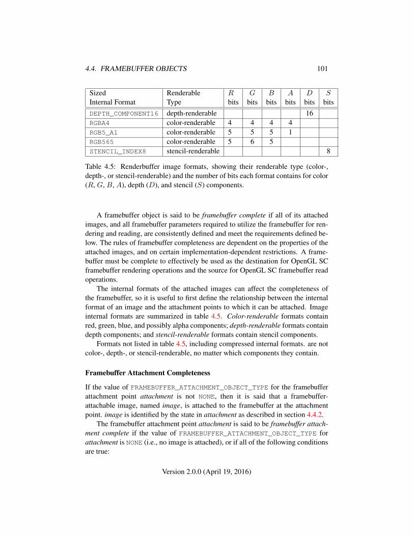
4.4. FRAMEBUFFER OBJECTS 101
Sized Renderable R G B A D SInternal Format Type bits bits bits bits bits bitsDEPTH_COMPONENT16 depth-renderable 16RGBA4 color-renderable 4 4 4 4RGB5_A1 color-renderable 5 5 5 1RGB565 color-renderable 5 6 5STENCIL_INDEX8 stencil-renderable 8
Table 4.5: Renderbuffer image formats, showing their renderable type (color-,depth-, or stencil-renderable) and the number of bits each format contains for color(R, G, B, A), depth (D), and stencil (S) components.
A framebuffer object is said to be framebuffer complete if all of its attachedimages, and all framebuffer parameters required to utilize the framebuffer for ren-dering and reading, are consistently defined and meet the requirements defined be-low. The rules of framebuffer completeness are dependent on the properties of theattached images, and on certain implementation-dependent restrictions. A frame-buffer must be complete to effectively be used as the destination for OpenGL SCframebuffer rendering operations and the source for OpenGL SC framebuffer readoperations.
The internal formats of the attached images can affect the completeness ofthe framebuffer, so it is useful to first define the relationship between the internalformat of an image and the attachment points to which it can be attached. Imageinternal formats are summarized in table 4.5. Color-renderable formats containred, green, blue, and possibly alpha components; depth-renderable formats containdepth components; and stencil-renderable formats contain stencil components.
Formats not listed in table 4.5, including compressed internal formats. are notcolor-, depth-, or stencil-renderable, no matter which components they contain.
Framebuffer Attachment Completeness
If the value of FRAMEBUFFER_ATTACHMENT_OBJECT_TYPE for the framebufferattachment point attachment is not NONE, then it is said that a framebuffer-attachable image, named image, is attached to the framebuffer at the attachmentpoint. image is identified by the state in attachment as described in section 4.4.2.
The framebuffer attachment point attachment is said to be framebuffer attach-ment complete if the value of FRAMEBUFFER_ATTACHMENT_OBJECT_TYPE forattachment is NONE (i.e., no image is attached), or if all of the following conditionsare true:
Version 2.0.0 (April 19, 2016)
4.4. FRAMEBUFFER OBJECTS 102
• image is a component of an existing object with the name specified byFRAMEBUFFER_ATTACHMENT_OBJECT_NAME, and of the type specified byFRAMEBUFFER_ATTACHMENT_OBJECT_TYPE.
• The width and height of image must be non-zero.
• If attachment is COLOR_ATTACHMENT0, then image must have a color-renderable internal format.
• If attachment is DEPTH_ATTACHMENT, then image must have a depth-renderable internal format.
• If attachment is STENCIL_ATTACHMENT, then image must have a stencil-renderable internal format.
Framebuffer Completeness
In this subsection, each rule is followed by an error enum in bold.The framebuffer object target is said to be framebuffer complete if all the fol-
lowing conditons are true:
• If target is the default framebuffer, the default frame buffer exists.
FRAMEBUFFER_UNDEFINED
• All framebuffer attachment points are framebuffer attachment complete.
FRAMEBUFFER_INCOMPLETE_ATTACHMENT
• There is at least one image attached to the framebuffer.
FRAMEBUFFER_INCOMPLETE_MISSING_ATTACHMENT
• All attached images have the same width and height.
FRAMEBUFFER_INCOMPLETE_DIMENSIONS
• The combination of internal formats of the attached images does not violatean implementation-dependent set of restrictions.
FRAMEBUFFER_UNSUPPORTED
The enum in bold after each clause of the framebuffer completeness rulesspecifies the return value of CheckFramebufferStatus that is generated whenthat clause is violated. If more than one clause is violated, it is implementation-dependent as to exactly which enum will be returned by CheckFramebufferSta-tus.
Version 2.0.0 (April 19, 2016)
4.4. FRAMEBUFFER OBJECTS 103
Performing any of the following actions may change whether the framebufferis considered complete or incomplete.
• Binding to a different framebuffer with BindFramebuffer.
• Attaching an image to the framebuffer with FramebufferTexture2D orFramebufferRenderbuffer.
• Detaching an image from the framebuffer with FramebufferTexture2D orFramebufferRenderbuffer.
• Associating a different window system-provided drawable, or no drawable,with the default framebuffer using a window system binding API such asEGL.
Although OpenGL SC defines a wide variety of internal formats forframebuffer-attachable images, such as texture images and renderbuffer images,some implementations may not support rendering to particular combinations ofinternal formats. If the combination of formats of the images attached to a frame-buffer object are not supported by the implementation, then the framebuffer is notcomplete under the clause labeled FRAMEBUFFER_UNSUPPORTED. There must ex-ist, however, at least one combination of internal formats for which the framebuffercannot be FRAMEBUFFER_UNSUPPORTED.
Because of the implementation-dependent clause of the framebuffer complete-ness test in particular, and because framebuffer completeness can change when theset of attached images is modified, it is strongly advised, though is not required,that an application check to see if the framebuffer is complete prior to rendering.The status of the framebuffer object currently bound to target can be queried bycalling
enum CheckFramebufferStatus( enum target );
If target is not FRAMEBUFFER, INVALID_ENUM is generated. If CheckFrame-bufferStatus generates an error, 0 is returned.
Otherwise, an enum is returned that identifies whether or not the framebufferbound to target is complete, and if not complete the enum identifies one of the rulesof framebuffer completeness that is violated. If the framebuffer is complete, thenFRAMEBUFFER_COMPLETE is returned.
Version 2.0.0 (April 19, 2016)
4.4. FRAMEBUFFER OBJECTS 104
Effects of Framebuffer Completeness on Framebuffer Operations
If the currently bound framebuffer is not framebuffer complete, then it is an errorto attempt to use the framebuffer for writing or reading. This means that ren-dering commands such as DrawArrays and DrawRangeElements, as well ascommands that read the framebuffer such as ReadnPixels, will generate the er-ror INVALID_FRAMEBUFFER_OPERATION if called while the framebuffer is notframebuffer complete.
4.4.6 Effects of Framebuffer State on Framebuffer Dependent Values
The values of the state variables listed in table 6.20 (Implementation DependantPixel Depths) may change when a change is made to FRAMEBUFFER_BINDING, tothe state of the currently bound framebuffer object, or to an image attached to thecurrently bound framebuffer object.
When FRAMEBUFFER_BINDING is zero, the values of the state variables listedin table 6.20 are implementation defined.
When FRAMEBUFFER_BINDING is non-zero, if the currently bound frame-buffer object is not framebuffer complete, then the values of the state variableslisted in table 6.20 are implementation specific.
When FRAMEBUFFER_BINDING is non-zero and the currently bound frame-buffer object is framebuffer complete, then the values of the state variables listedin table 6.20 are completely determined by FRAMEBUFFER_BINDING, the state ofthe currently bound framebuffer object, and the state of the images attached to thecurrently bound framebuffer object.
4.4.7 Mapping between Pixel and Element in Attached Image
When FRAMEBUFFER_BINDING is non-zero, an operation that writes to the frame-buffer modifies the image attached to the selected logical buffer, and an operationthat reads from the framebuffer reads from the image attached to the selected logi-cal buffer.
If the attached image is a renderbuffer image, then the window coordinates(xw, yw) correspond to the value in the renderbuffer image at the same coordinates.
If the attached image is a texture image, then the window coordinates (xw, yw)correspond to the value in the level zero array of that texture at the same coordi-nates.
Version 2.0.0 (April 19, 2016)
4.4. FRAMEBUFFER OBJECTS 105
Conversion to Framebuffer-Attachable Image Components
When an enabled color value is written to the framebuffer while FRAMEBUFFER_-BINDING is non-zero, for each draw buffer the R, G, B, and A values are convertedto internal components corresponding to the internal format of the framebuffer-attachable image attached to the selected logical buffer, and the resulting internalcomponents are written to the image attached to logical buffer. The masking opera-tions described by ColorMask, DepthMask, StencilMask, and StencilMaskSep-arate are also effective.
4.4.8 Errors
The error INVALID_FRAMEBUFFER_OPERATION is generated if the value returnedby CheckFramebufferStatus is not FRAMEBUFFER_COMPLETE, and any attemptsto render to or read from the framebuffer are made.
The error INVALID_OPERATION is generated if GetFramebufferAttach-mentParameteriv is called while the value of FRAMEBUFFER_BINDING is zero.
The error INVALID_OPERATION is generated if FramebufferRenderbufferor FramebufferTexture2D is called while the value of FRAMEBUFFER_BINDINGis zero.
The error INVALID_OPERATION is generated if RenderbufferStorage iscalled while the value of RENDERBUFFER_BINDING is zero.
The error INVALID_VALUE is generated if RenderbufferStorage is calledwith a width or height that is greater than MAX_RENDERBUFFER_SIZE.
The error INVALID_ENUM is generated if RenderbufferStorage is called withan internalformat that is not among the list of supported color, depth or stencilformats.
The error INVALID_OPERATION is generated if FramebufferRenderbufferis called and renderbuffer is not the name of a renderbuffer object.
The error INVALID_OPERATION is generated if FramebufferTexture2D iscalled and texture is not the name of a texture object.
The error INVALID_VALUE is generated if FramebufferTexture2D is calledwith a level that is less than zero.
The error INVALID_VALUE is generated if FramebufferTexture2D is calledwith a level that is greater than 0.
The error INVALID_ENUM is generated if CheckFramebufferStatus is calledand target is not FRAMEBUFFER.
The error OUT_OF_MEMORY is generated if OpenGL SC is unable to create adata store of the required size when calling RenderbufferStorage.
Version 2.0.0 (April 19, 2016)
Chapter 5
Special Functions
This chapter describes additional GL functionality that does not fit easily into anyof the preceding chapters: flushing and finishing (used to synchronize the GL com-mand stream), and hints.
5.1 Flush and Finish
The command
void Flush( void );
indicates that all commands that have previously been sent to the GL must completein finite time.
The command
void Finish( void );
forces all previous GL commands to complete. Finish does not return until alleffects from previously issued commands on GL client and server state and theframebuffer are fully realized.
5.2 Hints
Certain aspects of GL behavior, when there is room for variation, may be controlledwith hints. A hint is specified using
void Hint( enum target, enum hint );
106

5.2. HINTS 107
target is a symbolic constant indicating the behavior to be controlled, and hintis a symbolic constant indicating what type of behavior is desired. target mustbe GENERATE_MIPMAP_HINT, indicating the desired quality and performance ofmipmap level generation with GenerateMipmap. hint must be one of FASTEST,indicating that the most efficient option should be chosen; NICEST, indicating thatthe highest quality option should be chosen; and DONT_CARE, indicating no pref-erence in the matter.
The interpretation of hints is implementation-dependent. An implementationmay ignore them entirely.
The initial value of all hints is DONT_CARE.
Version 2.0.0 (April 19, 2016)
Chapter 6
State and State Requests
The state required to describe the GL machine is enumerated in section 6.2. Moststate is set through the calls described in previous chapters, and can be queriedusing the calls described in section 6.1.
6.1 Querying GL State
6.1.1 Simple Queries
Much of the GL state is completely identified by symbolic constants. The valuesof these state variables can be obtained using a set of Get commands. There arefour commands for obtaining simple state variables:
void GetBooleanv( enum value, boolean *data );void GetIntegerv( enum value, int *data );void GetFloatv( enum value, float *data );
The commands obtain boolean, integer, or floating-point state variables. value isa symbolic constant indicating the state variable to return. data is a pointer to ascalar or array of the indicated type in which to place the returned data. In addition
boolean IsEnabled( enum value );
can be used to determine if value is currently enabled (as with Enable) or disabled.
6.1.2 Data Conversions
State variables for which any command other than IsEnabled is listed as the querycommand can be obtained only by using that command. This ensures that no data
108
6.1. QUERYING GL STATE 109
conversions occur for queries. State variables for which IsEnabled is listed mayalso be queried by GetBooleanv.
Unless otherwise indicated, multi-valued state variables return their multiplevalues in the same order as they are given as arguments to the commands that setthem. For instance, the two DepthRangef parameters are returned in the order nfollowed by f.
Most texture state variables are qualified by the value of ACTIVE_TEXTURE todetermine which server texture state vector is queried. Tables 6.2, 6.7, 6.9, and 6.18indicate those state variables which are qualified by ACTIVE_TEXTURE duringstate queries. Texture state queries will result in an INVALID_OPERATION errorif the value of ACTIVE_TEXTURE is greater than or equal to MAX_COMBINED_-
TEXTURE_IMAGE_UNITS.
6.1.3 Enumerated Queries
Other commands exist to obtain state variables that are identified by a category(texture ID, buffer object name, etc.) as well as a symbolic constant. These are
The command
void GetTexParameter{if}v( enum target, enum value,T data );
returns information about target, which must be TEXTURE_2D, indicating thecurrently bound two-dimensional texture object. value is a symbolic value indicat-ing which texture parameter is to be obtained. value must be one of the symbolicvalues in table 3.8.
The command
void GetBufferParameteriv( enum target, enum value,T data );
returns information about target, which may be one of ARRAY_BUFFER orELEMENT_ARRAY_BUFFER, indicating the currently bound vertex array or elementarray buffer object. value is a symbolic value indicating which buffer object pa-rameter is to be obtained, and must be one of the symbolic values in table 2.6.
The command
void GetFramebufferAttachmentParameteriv( enum target,enum attachment, enum pname, int *params );
Version 2.0.0 (April 19, 2016)
6.1. QUERYING GL STATE 110
returns information about framebuffer objects. target must be FRAMEBUFFER.attachment must be one of the attachment points COLOR_ATTACHMENT0, DEPTH_-ATTACHMENT, or STENCIL_ATTACHMENT.
pname must be one of the following: FRAMEBUFFER_-
ATTACHMENT_OBJECT_TYPE, FRAMEBUFFER_ATTACHMENT_OBJECT_NAME, orFRAMEBUFFER_ATTACHMENT_TEXTURE_LEVEL.
If the framebuffer currently bound to target is zero, then INVALID_-
OPERATION is generated.Upon successful return from GetFramebufferAttachmentParameteriv, if
pname is FRAMEBUFFER_ATTACHMENT_OBJECT_TYPE, then param will containone of NONE, TEXTURE, or RENDERBUFFER, identifying the type of object whichcontains the attached image.
If the value of FRAMEBUFFER_ATTACHMENT_OBJECT_TYPE isRENDERBUFFER, then
• If pname is FRAMEBUFFER_ATTACHMENT_OBJECT_NAME, params will con-tain the name of the renderbuffer object which contains the attached image.
• Otherwise, INVALID_ENUM is generated.
If the value of FRAMEBUFFER_ATTACHMENT_OBJECT_TYPE is TEXTURE, then
• If pname is FRAMEBUFFER_ATTACHMENT_OBJECT_NAME, then params willcontain the name of the texture object which contains the attached image.
• If pname is FRAMEBUFFER_ATTACHMENT_TEXTURE_LEVEL, then paramswill contain the mipmap level of the texture object which contains the at-tached image.
• Otherwise, INVALID_ENUM is generated.
If the value of FRAMEBUFFER_ATTACHMENT_OBJECT_TYPE is NONE, thenquerying any other pname will generate INVALID_ENUM.
The command
void GetRenderbufferParameteriv( enum target, enum pname,int* params );
returns informationabout renderbuffer objects. target must be RENDERBUFFER. pname must be oneof the symbolic values in table 6.22 other than RENDERBUFFER_BINDING.
Version 2.0.0 (April 19, 2016)
6.1. QUERYING GL STATE 111
If the renderbuffer currently bound to target is zero, then INVALID_-
OPERATION is generated.Upon successful return from GetRenderbufferParameteriv, if pname
is RENDERBUFFER_WIDTH, RENDERBUFFER_HEIGHT, or RENDERBUFFER_-
INTERNAL_FORMAT, then params will contain the width in pixels, height in pixels,or internal format, respectively, of the image of the renderbuffer currently boundto target.
Upon successful return from GetRenderbufferParameteriv, if pname isRENDERBUFFER_RED_SIZE, RENDERBUFFER_GREEN_SIZE, RENDERBUFFER_-BLUE_SIZE, RENDERBUFFER_ALPHA_SIZE, RENDERBUFFER_DEPTH_SIZE, orRENDERBUFFER_STENCIL_SIZE, then params will contain the actual resolutions,(not the resolutions specified when the image array was defined), for the red, green,blue, alpha depth, or stencil components, respectively, of the image of the render-buffer currently bound to target.
Otherwise, INVALID_ENUM is generated.
6.1.4 String Queries
The command
ubyte *GetString( enum name );
returns a pointer to a static string describing some aspect of the current GL con-nection 1. The possible values for name are VENDOR, RENDERER, VERSION,SHADING_LANGUAGE_VERSION, and EXTENSIONS. The format of the RENDERERand VENDOR strings is implementation-dependent. The EXTENSIONS string con-tains a space separated list of extension names (the extension names themselves donot contain any spaces).
The VERSION string is laid out as follows:
"OpenGL SC N.M vendor-specific information"
The SHADING_LANGUAGE_VERSION string is laid out as follows:
"OpenGL SC GLSL ES N.M vendor-specific information"
The version number is either of the form major number.minor number ormajor number.minor number.release number, where the numbers all have one or
1Applications making copies of these static strings should never use a fixed-length buffer, becausethe strings may grow unpredictably between releases, resulting in buffer overflow when copying.This is particularly true of the EXTENSIONS string, which has become extremely long in someGL implementations.
Version 2.0.0 (April 19, 2016)
6.1. QUERYING GL STATE 112
more digits. The release number and vendor specific information are optional.However, if present, then they pertain to the server and their format and contentsare implementation-dependent.
GetString returns the version number (returned in the VERSION string) andthe extension names (returned in the EXTENSIONS string) that can be supportedon the connection. Thus, if the client and server support different versions and/orextensions, a compatible version and list of extensions is returned.
6.1.5 Program Queries
State stored program objects can be queried by commands that accept programobject names. These commands will generate the error INVALID_VALUE if theprovided name is not the name of a program object. If an error is generated, vari-ables used to hold return values are not modified.
The command
void GetProgramiv( uint program, enum pname,int *params );
returns properties of the program object named program in params. The parametervalue to return is specified by pname.
If pname is LINK STATUS, TRUE is returned if the shader was last loadedsuccessfully, and FALSE is returned otherwise.
The commands
void GetVertexAttribfv( uint index, enum pname,float *params );
void GetVertexAttribiv( uint index, enum pname,int *params );
obtain the vertex attribute state named by pname for the generic vertex attributenumbered index and places the information in the array params. pname must beone of VERTEX_ATTRIB_ARRAY_ENABLED, VERTEX_ATTRIB_ARRAY_SIZE,VERTEX_ATTRIB_ARRAY_STRIDE, VERTEX_ATTRIB_ARRAY_TYPE, VERTEX_-ATTRIB_ARRAY_NORMALIZED, VERTEX_ATTRIB_ARRAY_BUFFER_BINDING,or CURRENT_VERTEX_ATTRIB. Note that all the queries except CURRENT_-
VERTEX_ATTRIB return client state. The error INVALID_VALUE is generated ifindex is greater than or equal to MAX_VERTEX_ATTRIBS.
All but CURRENT_VERTEX_ATTRIB return information about generic vertexattribute arrays. The enable state of a generic vertex attribute array is set by thecommand EnableVertexAttribArray and cleared by DisableVertexAttribArray.
Version 2.0.0 (April 19, 2016)
6.2. STATE TABLES 113
The size, stride, type and normalized flag are set by the command VertexAttrib-Pointer. The query CURRENT_VERTEX_ATTRIB returns the current value for thegeneric attribute index.
The command
void GetVertexAttribPointerv( uint index, enum pname,void **pointer );
obtains the pointer named pname for vertex attribute numbered index and placesthe information in the array pointer. pname must be VERTEX_ATTRIB_ARRAY_-POINTER. The INVALID_VALUE error is generated if index is greater than or equalto MAX_VERTEX_ATTRIBS.
The commands
void GetnUniformfv( uint program, int location, sizeibufSize, float *params );
void GetnUniformiv( uint program, int location, sizeibufSize, int *params );
return the value or values of the uniform at location location for program objectprogram in the array params. The maximum number of bytes that may be writteninto params is specified by bufSize. The type of the uniform at location determinesthe number of values returned. The error INVALID_OPERATION is generated ifprogram has not been loaded successfully, or if location is not a valid location forprogram. In order to query the values of an array of uniforms, a GetnUniform*command needs to be issued for each array element. If the uniform queried is amatrix, the values of the matrix are returned in column major order. If an erroroccurred, the return parameter params will be unmodified.
6.2 State Tables
The tables on the following pages indicate which state variables are obtained withwhat commands. State variables that can be obtained using GetBooleanv, Get-Integerv, or GetFloatv are listed with just one of these commands – the one thatis most appropriate given the type of the data to be returned. These state variablescannot be obtained using IsEnabled. However, state variables for which IsEn-abled is listed as the query command can also be obtained using GetBooleanv.State variables for which any command other than IsEnabled is listed as the querycommand can be obtained only by using that command.
Version 2.0.0 (April 19, 2016)
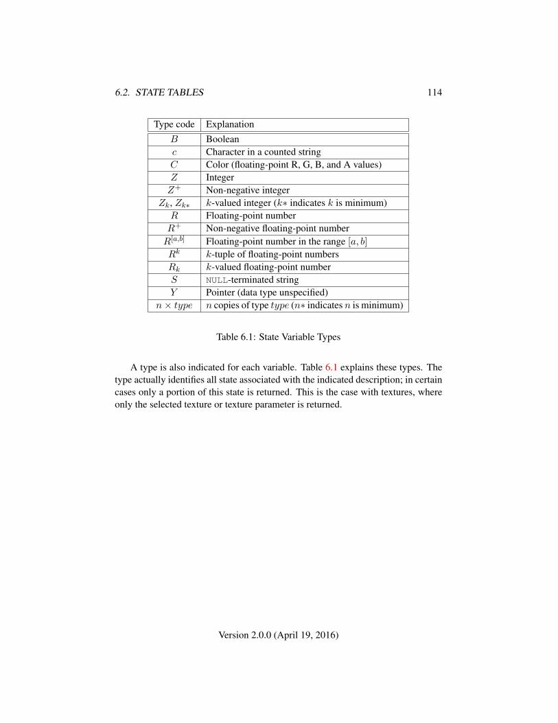
6.2. STATE TABLES 114
Type code ExplanationB Booleanc Character in a counted stringC Color (floating-point R, G, B, and A values)Z IntegerZ+ Non-negative integer
Zk, Zk∗ k-valued integer (k∗ indicates k is minimum)R Floating-point numberR+ Non-negative floating-point numberR[a,b] Floating-point number in the range [a, b]
Rk k-tuple of floating-point numbersRk k-valued floating-point numberS NULL-terminated stringY Pointer (data type unspecified)
n× type n copies of type type (n∗ indicates n is minimum)
Table 6.1: State Variable Types
A type is also indicated for each variable. Table 6.1 explains these types. Thetype actually identifies all state associated with the indicated description; in certaincases only a portion of this state is returned. This is the case with textures, whereonly the selected texture or texture parameter is returned.
Version 2.0.0 (April 19, 2016)
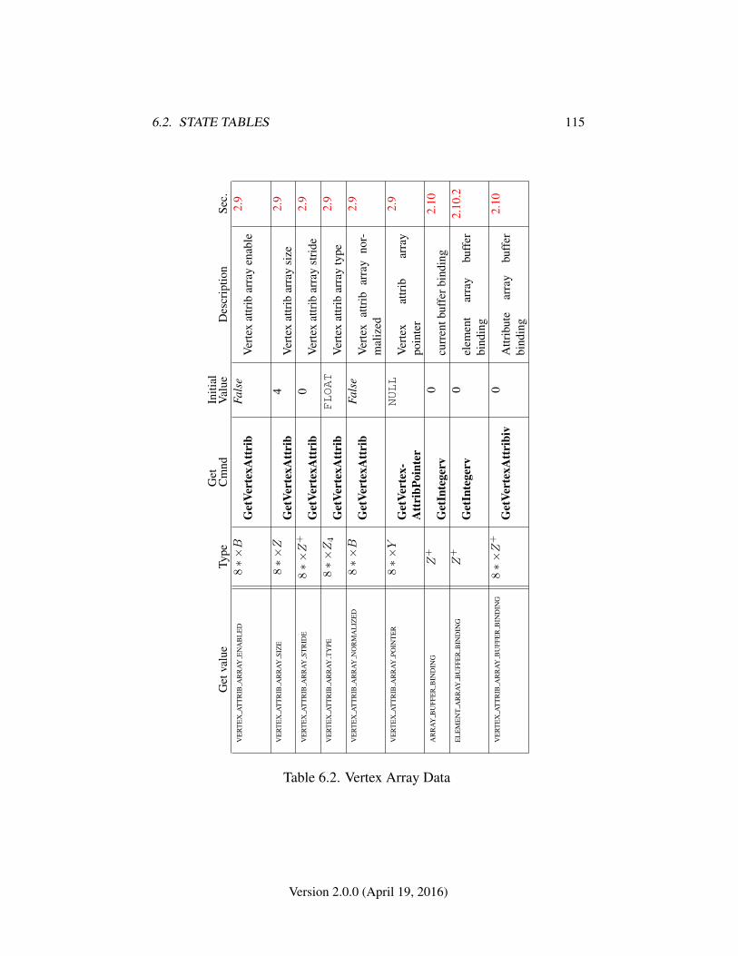
6.2. STATE TABLES 115
Get
valu
eTy
peG
etC
mnd
Initi
alV
alue
Des
crip
tion
Sec.
VE
RT
EX
AT
TR
IBA
RR
AY
EN
AB
LE
D8∗×B
Get
Vert
exA
ttri
bFa
lse
Ver
tex
attr
ibar
ray
enab
le2.
9
VE
RT
EX
AT
TR
IBA
RR
AY
SIZ
E8∗×Z
Get
Vert
exA
ttri
b4
Ver
tex
attr
ibar
ray
size
2.9
VE
RT
EX
AT
TR
IBA
RR
AY
STR
IDE
8∗×Z
+
Get
Vert
exA
ttri
b0
Ver
tex
attr
ibar
ray
stri
de2.
9
VE
RT
EX
AT
TR
IBA
RR
AY
TY
PE8∗×Z4
Get
Vert
exA
ttri
bFLOAT
Ver
tex
attr
ibar
ray
type
2.9
VE
RT
EX
AT
TR
IBA
RR
AY
NO
RM
AL
IZE
D8∗×B
Get
Vert
exA
ttri
bFa
lse
Ver
tex
attr
ibar
ray
nor-
mal
ized
2.9
VE
RT
EX
AT
TR
IBA
RR
AY
POIN
TE
R8∗×Y
Get
Vert
ex-
Att
ribP
oint
er
NULL
Ver
tex
attr
ibar
ray
poin
ter
2.9
AR
RA
YB
UFF
ER
BIN
DIN
GZ
+
Get
Inte
gerv
0cu
rren
tbuf
ferb
indi
ng2.
10
EL
EM
EN
TA
RR
AY
BU
FFE
RB
IND
ING
Z+
Get
Inte
gerv
0el
emen
tar
ray
buff
erbi
ndin
g
2.10
.2
VE
RT
EX
AT
TR
IBA
RR
AY
BU
FFE
RB
IND
ING
8∗×Z
+
Get
Vert
exA
ttri
biv
0A
ttrib
ute
arra
ybu
ffer
bind
ing
2.10
Table 6.2. Vertex Array Data
Version 2.0.0 (April 19, 2016)
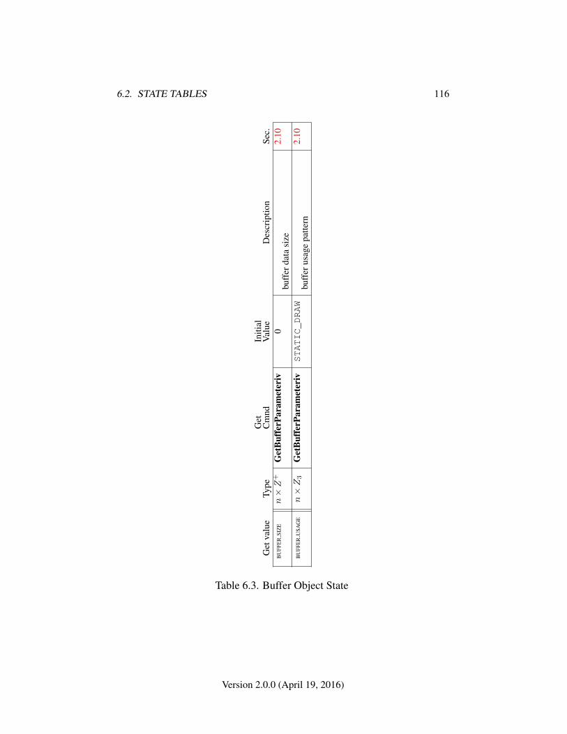
6.2. STATE TABLES 116
Get
valu
eTy
peG
etC
mnd
Initi
alV
alue
Des
crip
tion
Sec.
BU
FFE
RSI
ZE
n×Z
+G
etB
uffe
rPar
amet
eriv
0bu
ffer
data
size
2.10
BU
FFE
RU
SAG
En×Z3
Get
Buf
ferP
aram
eter
ivSTATIC_DRAW
buff
erus
age
patte
rn2.
10
Table 6.3. Buffer Object State
Version 2.0.0 (April 19, 2016)
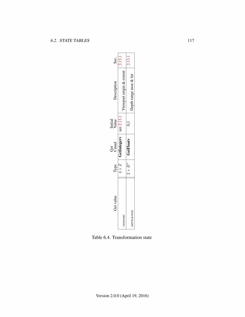
6.2. STATE TABLES 117
Get
valu
eTy
peG
etC
mnd
Initi
alV
alue
Des
crip
tion
Sec.
VIE
WPO
RT
4×Z
Get
Inte
gerv
see
2.13
.1V
iew
port
orig
in&
exte
nt2.
13.1
DE
PTH
RA
NG
E2×R
+G
etFl
oatv
0,1
Dep
thra
nge
near
&fa
r2.
13.1
Table 6.4. Transformation state
Version 2.0.0 (April 19, 2016)
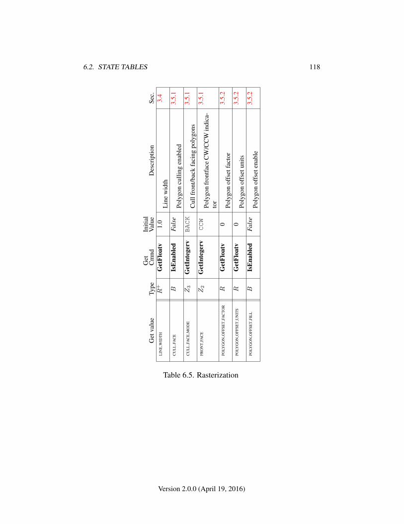
6.2. STATE TABLES 118
Get
valu
eTy
peG
etC
mnd
Initi
alV
alue
Des
crip
tion
Sec.
LIN
EW
IDT
HR
+G
etFl
oatv
1.0
Lin
ew
idth
3.4
CU
LL
FAC
EB
IsE
nabl
edFa
lse
Poly
gon
culli
ngen
able
d3.
5.1
CU
LL
FAC
EM
OD
EZ3
Get
Inte
gerv
BACK
Cul
lfro
nt/b
ack
faci
ngpo
lygo
ns3.
5.1
FRO
NT
FAC
EZ2
Get
Inte
gerv
CCW
Poly
gon
fron
tface
CW
/CC
Win
dica
-to
r
3.5.
1
POLY
GO
NO
FFSE
TFA
CTO
RR
Get
Floa
tv0
Poly
gon
offs
etfa
ctor
3.5.
2
POLY
GO
NO
FFSE
TU
NIT
SR
Get
Floa
tv0
Poly
gon
offs
etun
its3.
5.2
POLY
GO
NO
FFSE
TFI
LL
BIs
Ena
bled
Fals
ePo
lygo
nof
fset
enab
le3.
5.2
Table 6.5. Rasterization
Version 2.0.0 (April 19, 2016)
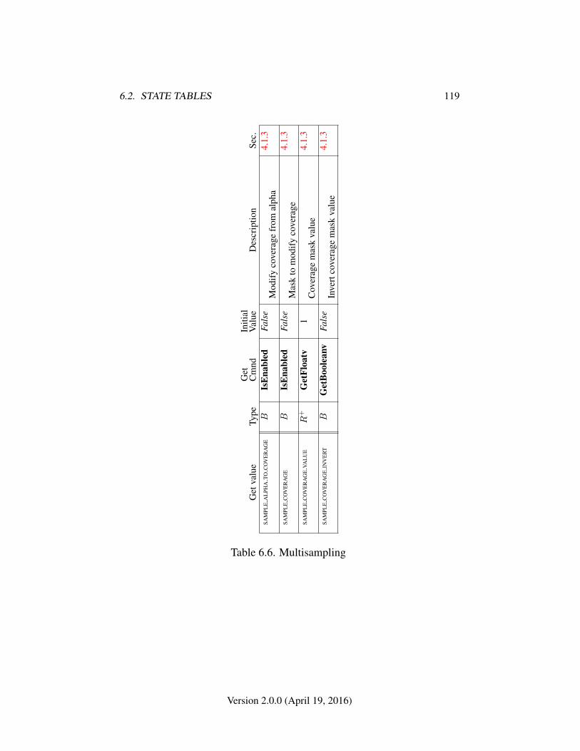
6.2. STATE TABLES 119
Get
valu
eTy
peG
etC
mnd
Initi
alV
alue
Des
crip
tion
Sec.
SAM
PLE
AL
PHA
TOC
OV
ER
AG
EB
IsE
nabl
edFa
lse
Mod
ify
cove
rage
from
alph
a4.
1.3
SAM
PLE
CO
VE
RA
GE
BIs
Ena
bled
Fals
eM
ask
tom
odif
yco
vera
ge4.
1.3
SAM
PLE
CO
VE
RA
GE
VAL
UE
R+
Get
Floa
tv1
Cov
erag
em
ask
valu
e4.
1.3
SAM
PLE
CO
VE
RA
GE
INV
ER
TB
Get
Boo
lean
vFa
lse
Inve
rtco
vera
gem
ask
valu
e4.
1.3
Table 6.6. Multisampling
Version 2.0.0 (April 19, 2016)
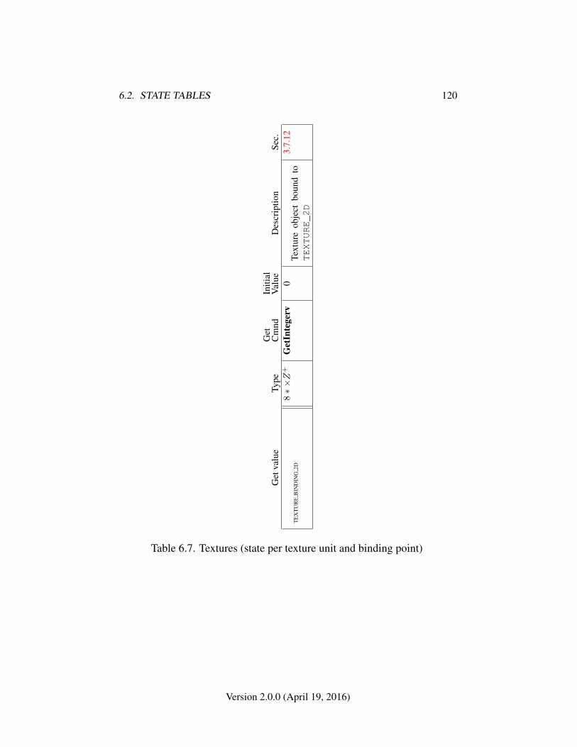
6.2. STATE TABLES 120
Get
valu
eTy
peG
etC
mnd
Initi
alV
alue
Des
crip
tion
Sec.
TE
XT
UR
EB
IND
ING
2D8∗×Z
+G
etIn
tege
rv0
Text
ure
obje
ctbo
und
toTEXTURE_2D
3.7.
12
Table 6.7. Textures (state per texture unit and binding point)
Version 2.0.0 (April 19, 2016)
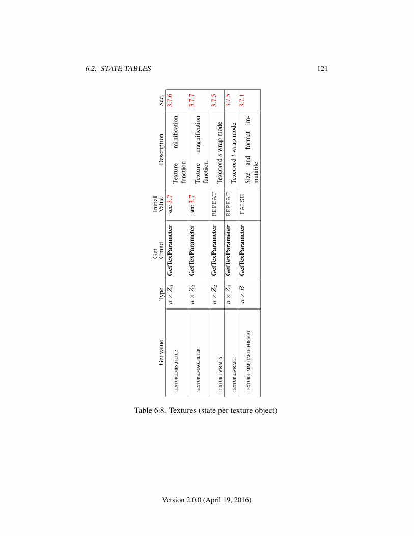
6.2. STATE TABLES 121
Get
valu
eTy
peG
etC
mnd
Initi
alV
alue
Des
crip
tion
Sec.
TE
XT
UR
EM
INFI
LTE
Rn×Z6
Get
TexP
aram
eter
see
3.7
Text
ure
min
ifica
tion
func
tion
3.7.
6
TE
XT
UR
EM
AG
FILT
ER
n×Z2
Get
TexP
aram
eter
see
3.7
Text
ure
mag
nific
atio
nfu
nctio
n
3.7.
7
TE
XT
UR
EW
RA
PS
n×Z2
Get
TexP
aram
eter
REPEAT
Texc
oords
wra
pm
ode
3.7.
5
TE
XT
UR
EW
RA
PT
n×Z2
Get
TexP
aram
eter
REPEAT
Texc
oordt
wra
pm
ode
3.7.
5
TE
XT
UR
EIM
MU
TAB
LE
FOR
MA
Tn×B
Get
TexP
aram
eter
FALSE
Size
and
form
atim
-m
utab
le
3.7.
1
Table 6.8. Textures (state per texture object)
Version 2.0.0 (April 19, 2016)
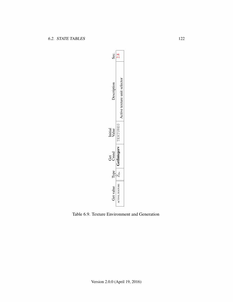
6.2. STATE TABLES 122
Get
valu
eTy
peG
etC
mnd
Initi
alV
alue
Des
crip
tion
Sec.
AC
TIV
ET
EX
TU
RE
Z8∗
Get
Inte
gerv
TEXTURE0
Act
ive
text
ure
unit
sele
ctor
2.8
Table 6.9. Texture Environment and Generation
Version 2.0.0 (April 19, 2016)
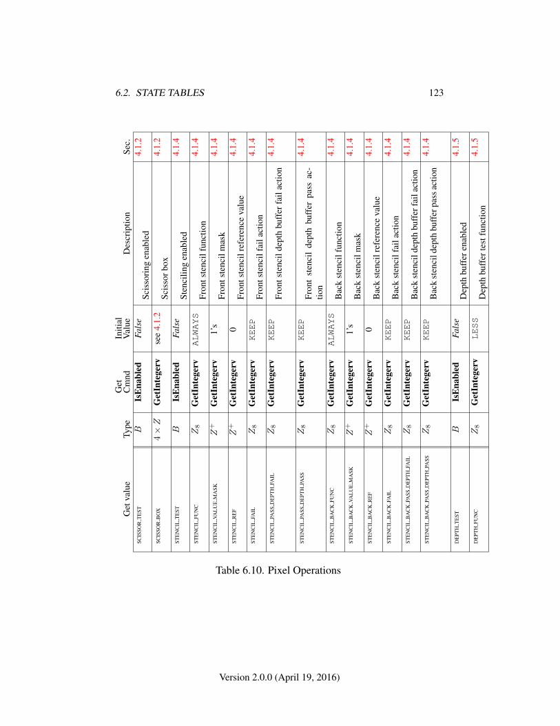
6.2. STATE TABLES 123
Get
valu
eTy
peG
etC
mnd
Initi
alV
alue
Des
crip
tion
Sec.
SCIS
SOR
TE
STB
IsE
nabl
edFa
lse
Scis
sori
ngen
able
d4.
1.2
SCIS
SOR
BO
X4×Z
Get
Inte
gerv
see
4.1.
2Sc
isso
rbox
4.1.
2
STE
NC
ILT
EST
BIs
Ena
bled
Fals
eSt
enci
ling
enab
led
4.1.
4
STE
NC
ILFU
NC
Z8
Get
Inte
gerv
ALWAYS
Fron
tste
ncil
func
tion
4.1.
4
STE
NC
ILVA
LU
EM
ASK
Z+
Get
Inte
gerv
1’s
Fron
tste
ncil
mas
k4.
1.4
STE
NC
ILR
EF
Z+
Get
Inte
gerv
0Fr
onts
tenc
ilre
fere
nce
valu
e4.
1.4
STE
NC
ILFA
ILZ8
Get
Inte
gerv
KEEP
Fron
tste
ncil
fail
actio
n4.
1.4
STE
NC
ILPA
SSD
EPT
HFA
ILZ8
Get
Inte
gerv
KEEP
Fron
tste
ncil
dept
hbu
ffer
fail
actio
n4.
1.4
STE
NC
ILPA
SSD
EPT
HPA
SSZ8
Get
Inte
gerv
KEEP
Fron
tst
enci
lde
pth
buff
erpa
ssac
-tio
n
4.1.
4
STE
NC
ILB
AC
KFU
NC
Z8
Get
Inte
gerv
ALWAYS
Bac
kst
enci
lfun
ctio
n4.
1.4
STE
NC
ILB
AC
KVA
LU
EM
ASK
Z+
Get
Inte
gerv
1’s
Bac
kst
enci
lmas
k4.
1.4
STE
NC
ILB
AC
KR
EF
Z+
Get
Inte
gerv
0B
ack
sten
cilr
efer
ence
valu
e4.
1.4
STE
NC
ILB
AC
KFA
ILZ8
Get
Inte
gerv
KEEP
Bac
kst
enci
lfai
lact
ion
4.1.
4
STE
NC
ILB
AC
KPA
SSD
EPT
HFA
ILZ8
Get
Inte
gerv
KEEP
Bac
kst
enci
ldep
thbu
ffer
fail
actio
n4.
1.4
STE
NC
ILB
AC
KPA
SSD
EPT
HPA
SSZ8
Get
Inte
gerv
KEEP
Bac
kst
enci
ldep
thbu
ffer
pass
actio
n4.
1.4
DE
PTH
TE
STB
IsE
nabl
edFa
lse
Dep
thbu
ffer
enab
led
4.1.
5
DE
PTH
FUN
CZ8
Get
Inte
gerv
LESS
Dep
thbu
ffer
test
func
tion
4.1.
5
Table 6.10. Pixel Operations
Version 2.0.0 (April 19, 2016)
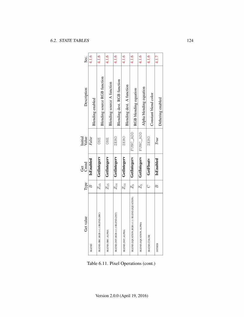
6.2. STATE TABLES 124
Get
valu
eTy
peG
etC
mnd
Initi
alV
alue
Des
crip
tion
Sec.
BL
EN
DB
IsE
nabl
edFa
lse
Ble
ndin
gen
able
d4.
1.6
BL
EN
DSR
CR
GB
(v1.
1:B
LE
ND
SRC
)Z15
Get
Inte
gerv
ONE
Ble
ndin
gso
urce
RG
Bfu
nctio
n4.
1.6
BL
EN
DSR
CA
LPH
AZ15
Get
Inte
gerv
ONE
Ble
ndin
gso
urce
Afu
nctio
n4.
1.6
BL
EN
DD
STR
GB
(v1.
1:B
LE
ND
DST
)Z14
Get
Inte
gerv
ZERO
Ble
ndin
gde
st.R
GB
func
tion
4.1.
6
BL
EN
DD
STA
LPH
AZ14
Get
Inte
gerv
ZERO
Ble
ndin
gde
st.A
func
tion
4.1.
6
BL
EN
DE
QU
AT
ION
RG
B(v
1.1:
BL
EN
DE
QU
AT
ION
)Z5
Get
Inte
gerv
FUNC_ADD
RG
Bbl
endi
ngeq
uatio
n4.
1.6
BL
EN
DE
QU
AT
ION
AL
PHA
Z5
Get
Inte
gerv
FUNC_ADD
Alp
habl
endi
ngeq
uatio
n4.
1.6
BL
EN
DC
OL
OR
CG
etFl
oatv
ZERO
Con
stan
tble
ndco
lor
4.1.
6
DIT
HE
RB
IsE
nabl
edTr
ueD
ither
ing
enab
led
4.1.
7
Table 6.11. Pixel Operations (cont.)
Version 2.0.0 (April 19, 2016)
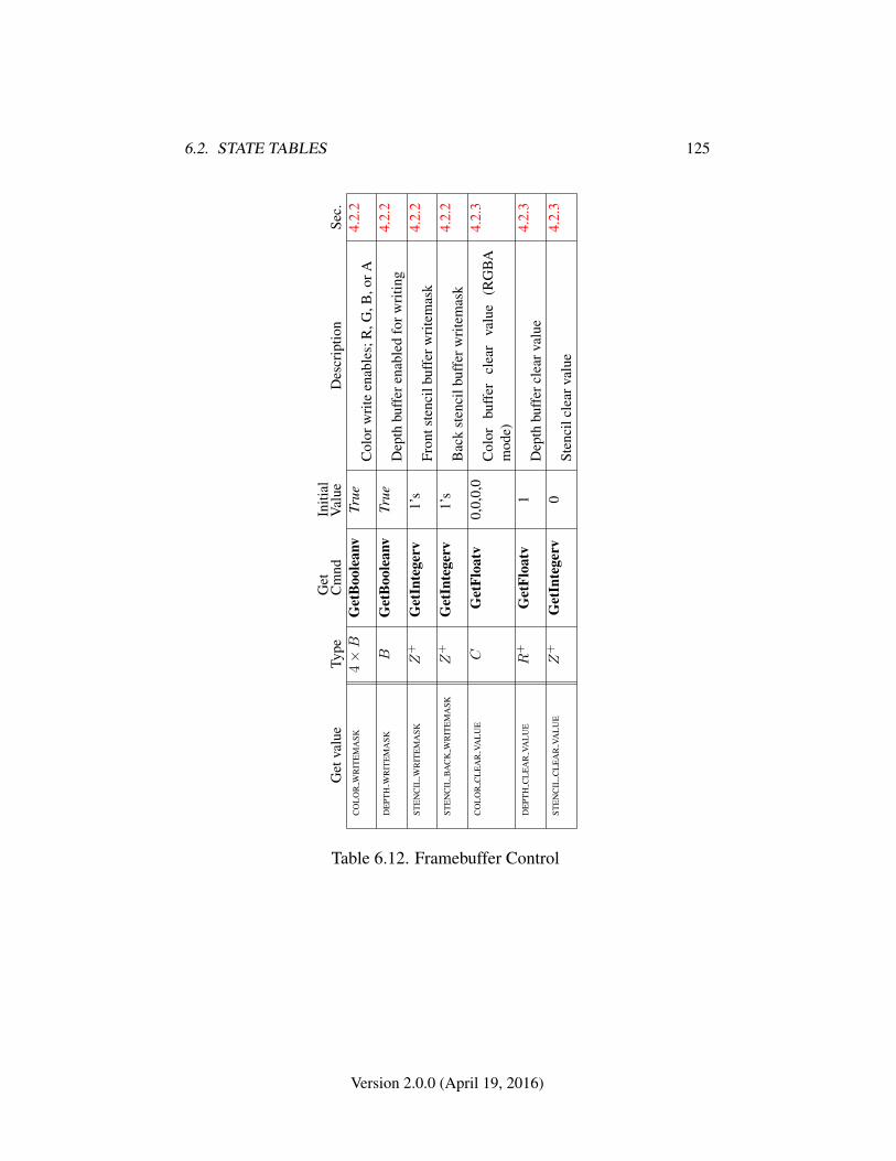
6.2. STATE TABLES 125
Get
valu
eTy
peG
etC
mnd
Initi
alV
alue
Des
crip
tion
Sec.
CO
LO
RW
RIT
EM
ASK
4×B
Get
Boo
lean
vTr
ueC
olor
wri
teen
able
s;R
,G,B
,orA
4.2.
2
DE
PTH
WR
ITE
MA
SKB
Get
Boo
lean
vTr
ueD
epth
buff
eren
able
dfo
rwri
ting
4.2.
2
STE
NC
ILW
RIT
EM
ASK
Z+
Get
Inte
gerv
1’s
Fron
tste
ncil
buff
erw
rite
mas
k4.
2.2
STE
NC
ILB
AC
KW
RIT
EM
ASK
Z+
Get
Inte
gerv
1’s
Bac
kst
enci
lbuf
ferw
rite
mas
k4.
2.2
CO
LO
RC
LE
AR
VAL
UE
CG
etFl
oatv
0,0,
0,0
Col
orbu
ffer
clea
rva
lue
(RG
BA
mod
e)
4.2.
3
DE
PTH
CL
EA
RVA
LU
ER
+G
etFl
oatv
1D
epth
buff
ercl
earv
alue
4.2.
3
STE
NC
ILC
LE
AR
VAL
UE
Z+
Get
Inte
gerv
0St
enci
lcle
arva
lue
4.2.
3
Table 6.12. Framebuffer Control
Version 2.0.0 (April 19, 2016)
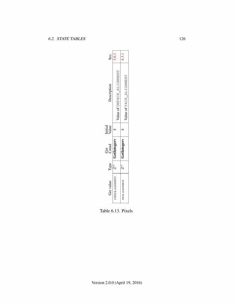
6.2. STATE TABLES 126
Get
valu
eTy
peG
etC
mnd
Initi
alV
alue
Des
crip
tion
Sec.
UN
PAC
KA
LIG
NM
EN
TZ
+G
etIn
tege
rv4
Val
ueofUNPACK_ALIGNMENT
3.6.
1
PAC
KA
LIG
NM
EN
TZ
+G
etIn
tege
rv4
Val
ueofPACK_ALIGNMENT
4.3.
1
Table 6.13. Pixels
Version 2.0.0 (April 19, 2016)
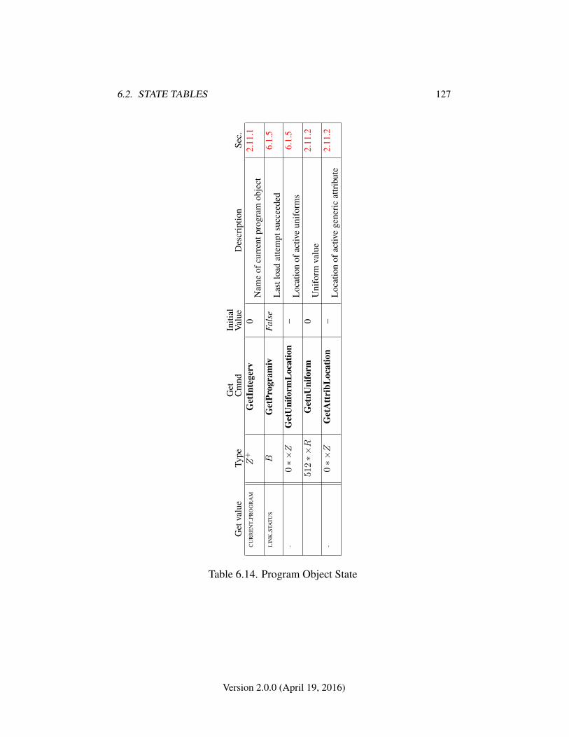
6.2. STATE TABLES 127
Get
valu
eTy
peG
etC
mnd
Initi
alV
alue
Des
crip
tion
Sec.
CU
RR
EN
TPR
OG
RA
MZ
+G
etIn
tege
rv0
Nam
eof
curr
entp
rogr
amob
ject
2.11
.1
LIN
KST
AT
US
BG
etPr
ogra
miv
Fals
eL
astl
oad
atte
mpt
succ
eede
d6.
1.5
-0∗×Z
Get
Uni
form
Loc
atio
n–
Loc
atio
nof
activ
eun
ifor
ms
6.1.
5
512∗×R
Get
nUni
form
0U
nifo
rmva
lue
2.11
.2
-0∗×Z
Get
Att
ribL
ocat
ion
–L
ocat
ion
ofac
tive
gene
ric
attr
ibut
e2.
11.2
Table 6.14. Program Object State
Version 2.0.0 (April 19, 2016)
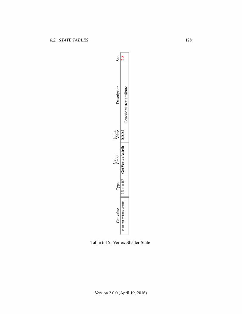
6.2. STATE TABLES 128
Get
valu
eTy
peG
etC
mnd
Initi
alV
alue
Des
crip
tion
Sec.
CU
RR
EN
TV
ER
TE
XA
TT
RIB
16∗×R
4G
etVe
rtex
Att
rib
0,0,
0,1
Gen
eric
vert
exat
trib
ute
2.8
Table 6.15. Vertex Shader State
Version 2.0.0 (April 19, 2016)
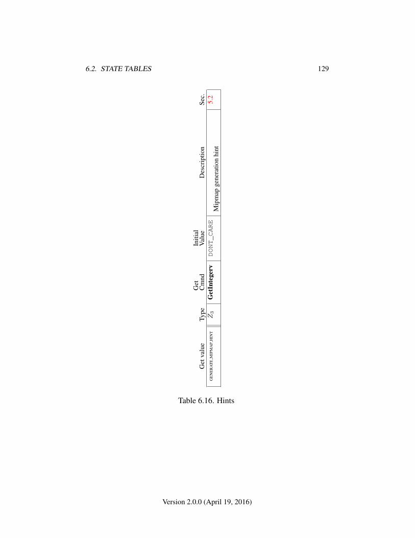
6.2. STATE TABLES 129
Get
valu
eTy
peG
etC
mnd
Initi
alV
alue
Des
crip
tion
Sec.
GE
NE
RA
TE
MIP
MA
PH
INT
Z3
Get
Inte
gerv
DONT_CARE
Mip
map
gene
ratio
nhi
nt5.
2
Table 6.16. Hints
Version 2.0.0 (April 19, 2016)
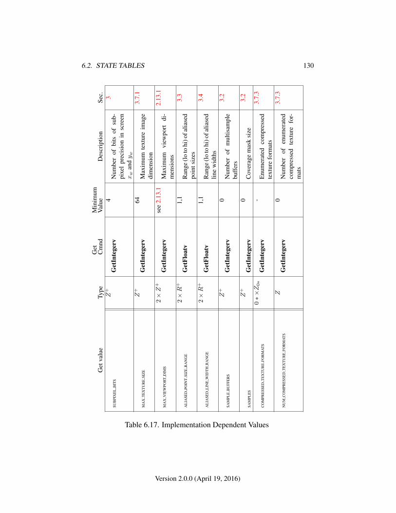
6.2. STATE TABLES 130
Get
valu
eTy
peG
etC
mnd
Min
imum
Val
ueD
escr
iptio
nSe
c.
SUB
PIX
EL
BIT
SZ
+
Get
Inte
gerv
4N
umbe
rof
bits
ofsu
b-pi
xel
prec
isio
nin
scre
enxw
andy w
3
MA
XT
EX
TU
RE
SIZ
EZ
+
Get
Inte
gerv
64M
axim
umte
xtur
eim
age
dim
ensi
on
3.7.
1
MA
XV
IEW
POR
TD
IMS
2×Z
+
Get
Inte
gerv
see
2.13
.1M
axim
umvi
ewpo
rtdi
-m
ensi
ons
2.13
.1
AL
IASE
DPO
INT
SIZ
ER
AN
GE
2×R
+
Get
Floa
tv1,
1R
ange
(lo
tohi
)ofa
liase
dpo
ints
izes
3.3
AL
IASE
DL
INE
WID
TH
RA
NG
E2×R
+
Get
Floa
tv1,
1R
ange
(lo
tohi
)ofa
liase
dlin
ew
idth
s
3.4
SAM
PLE
BU
FFE
RS
Z+
Get
Inte
gerv
0N
umbe
rof
mul
tisam
ple
buff
ers
3.2
SAM
PLE
SZ
+
Get
Inte
gerv
0C
over
age
mas
ksi
ze3.
2
CO
MPR
ESS
ED
TE
XT
UR
EFO
RM
AT
S0∗×Z0∗
Get
Inte
gerv
-E
num
erat
edco
mpr
esse
dte
xtur
efo
rmat
s
3.7.
3
NU
MC
OM
PRE
SSE
DT
EX
TU
RE
FOR
MA
TS
ZG
etIn
tege
rv0
Num
ber
ofen
umer
ated
com
pres
sed
text
ure
for-
mat
s
3.7.
3
Table 6.17. Implementation Dependent Values
Version 2.0.0 (April 19, 2016)
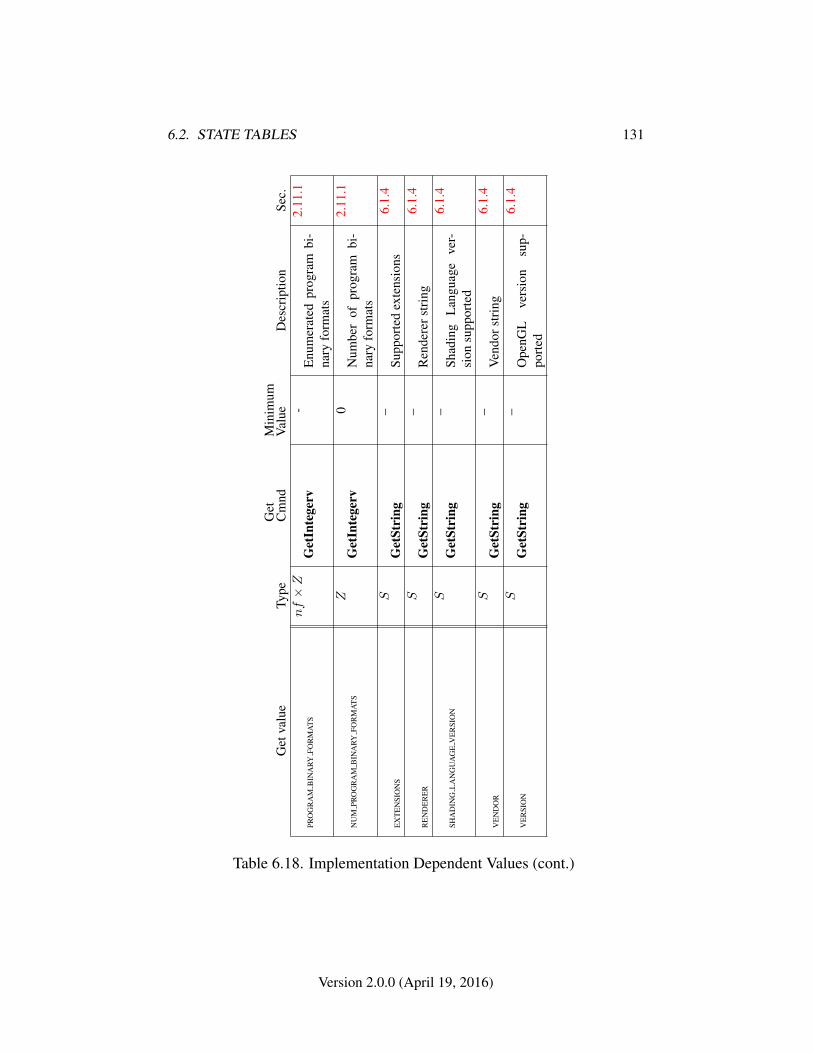
6.2. STATE TABLES 131
Get
valu
eTy
peG
etC
mnd
Min
imum
Val
ueD
escr
iptio
nSe
c.
PRO
GR
AM
BIN
ARY
FOR
MA
TS
nf×Z
Get
Inte
gerv
-E
num
erat
edpr
ogra
mbi
-na
ryfo
rmat
s
2.11
.1
NU
MPR
OG
RA
MB
INA
RYFO
RM
AT
SZ
Get
Inte
gerv
0N
umbe
rof
prog
ram
bi-
nary
form
ats
2.11
.1
EX
TE
NSI
ON
SS
Get
Stri
ng–
Supp
orte
dex
tens
ions
6.1.
4
RE
ND
ER
ER
SG
etSt
ring
–R
ende
rers
trin
g6.
1.4
SHA
DIN
GL
AN
GU
AG
EV
ER
SIO
NS
Get
Stri
ng–
Shad
ing
Lan
guag
eve
r-si
onsu
ppor
ted
6.1.
4
VE
ND
OR
SG
etSt
ring
–V
endo
rstr
ing
6.1.
4
VE
RSI
ON
SG
etSt
ring
–O
penG
Lve
rsio
nsu
p-po
rted
6.1.
4
Table 6.18. Implementation Dependent Values (cont.)
Version 2.0.0 (April 19, 2016)

6.2. STATE TABLES 132
Get
valu
eTy
peG
etC
mnd
Min
imum
Val
ueD
escr
iptio
nSe
c.
MA
XV
ER
TE
XA
TT
RIB
SZ
+
Get
Inte
gerv
8N
umbe
rof
activ
eve
rtex
attr
ibut
es
2.8
MA
XV
ER
TE
XU
NIF
OR
MV
EC
TOR
SZ
+
Get
Inte
gerv
128
Num
ber
ofve
ctor
sfo
rve
rtex
shad
erun
ifor
mva
riab
les
2.11
.2
MA
XVA
RYIN
GV
EC
TOR
SZ
+
Get
Inte
gerv
8N
umbe
rof
vect
ors
for
vary
ing
vari
able
s
2.11
.2
MA
XC
OM
BIN
ED
TE
XT
UR
EIM
AG
EU
NIT
SZ
+
Get
Inte
gerv
8To
tal
num
ber
ofte
xtur
eun
itsac
cess
ible
byth
eG
L
2.11
.3
MA
XV
ER
TE
XT
EX
TU
RE
IMA
GE
UN
ITS
Z+
Get
Inte
gerv
0N
umbe
roft
extu
reim
age
units
acce
ssib
leby
ave
r-te
xsh
ader
2.11
.3
MA
XT
EX
TU
RE
IMA
GE
UN
ITS
Z+
Get
Inte
gerv
8N
umbe
roft
extu
reim
age
units
acce
ssib
leby
frag
-m
entp
roce
ssin
g
2.11
.3
MA
XFR
AG
ME
NT
UN
IFO
RM
VE
CTO
RS
Z+
Get
Inte
gerv
16N
umbe
rof
vect
ors
for
frag
.sh
ader
unif
orm
vari
able
s
3.8.
1
MA
XR
EN
DE
RB
UFF
ER
SIZ
EZ
+
Get
Inte
gerv
1M
axim
umre
nder
buff
ersi
ze
4.4.
3
Table 6.19. Implementation Dependent Values (cont.)
Version 2.0.0 (April 19, 2016)
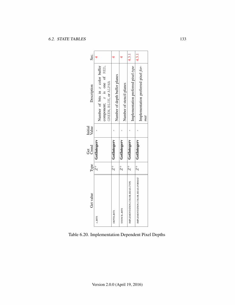
6.2. STATE TABLES 133
Get
valu
eTy
peG
etC
mnd
Initi
alV
alue
Des
crip
tion
Sec.
xB
ITS
Z+
Get
Inte
gerv
-N
umbe
rof
bits
inx
colo
rbu
ffer
com
pone
nt;
xis
one
ofRED
,GREEN
,BLUE
,orALPHA
4
DE
PTH
BIT
SZ
+G
etIn
tege
rv-
Num
bero
fdep
thbu
ffer
plan
es4
STE
NC
ILB
ITS
Z+
Get
Inte
gerv
-N
umbe
rofs
tenc
ilpl
anes
4
IMPL
EM
EN
TAT
ION
CO
LO
RR
EA
DT
YPE
Z+
Get
Inte
gerv
-Im
plem
enta
tion
pref
erre
dpi
xelt
ype
4.3.
1
IMPL
EM
EN
TAT
ION
CO
LO
RR
EA
DFO
RM
AT
Z+
Get
Inte
gerv
-Im
plem
enta
tion
pref
erre
dpi
xel
for-
mat
4.3.
1
Table 6.20. Implementation Dependent Pixel Depths
Version 2.0.0 (April 19, 2016)
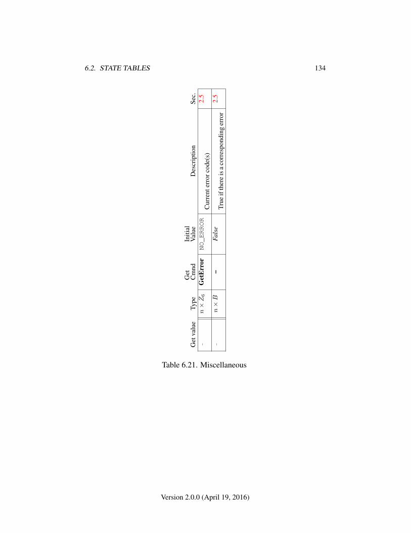
6.2. STATE TABLES 134
Get
valu
eTy
peG
etC
mnd
Initi
alV
alue
Des
crip
tion
Sec.
–n×Z6
Get
Err
orNO_ERROR
Cur
rent
erro
rcod
e(s)
2.5
–n×B
–Fa
lse
True
ifth
ere
isa
corr
espo
ndin
ger
ror
2.5
Table 6.21. Miscellaneous
Version 2.0.0 (April 19, 2016)
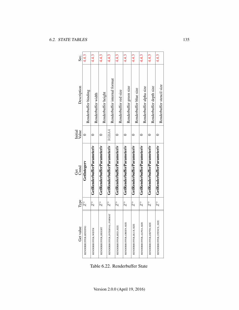
6.2. STATE TABLES 135
Get
valu
eTy
peG
etC
mnd
Initi
alV
alue
Des
crip
tion
Sec.
RE
ND
ER
BU
FFE
RB
IND
ING
Z+
Get
Inte
gerv
0R
ende
rbuf
ferb
indi
ng4.
4.3
RE
ND
ER
BU
FFE
RW
IDT
HZ
+G
etR
ende
rbuf
ferP
aram
eter
iv0
Ren
derb
uffe
rwid
th4.
4.3
RE
ND
ER
BU
FFE
RH
EIG
HT
Z+
Get
Ren
derb
uffe
rPar
amet
eriv
0R
ende
rbuf
ferh
eigh
t4.
4.3
RE
ND
ER
BU
FFE
RIN
TE
RN
AL
FOR
MA
TZ
+G
etR
ende
rbuf
ferP
aram
eter
ivRGBA4
Ren
derb
uffe
rint
erna
lfor
mat
4.4.
3
RE
ND
ER
BU
FFE
RR
ED
SIZ
EZ
+G
etR
ende
rbuf
ferP
aram
eter
iv0
Ren
derb
uffe
rred
size
4.4.
3
RE
ND
ER
BU
FFE
RG
RE
EN
SIZ
EZ
+G
etR
ende
rbuf
ferP
aram
eter
iv0
Ren
derb
uffe
rgre
ensi
ze4.
4.3
RE
ND
ER
BU
FFE
RB
LU
ESI
ZE
Z+
Get
Ren
derb
uffe
rPar
amet
eriv
0R
ende
rbuf
ferb
lue
size
4.4.
3
RE
ND
ER
BU
FFE
RA
LPH
ASI
ZE
Z+
Get
Ren
derb
uffe
rPar
amet
eriv
0R
ende
rbuf
fera
lpha
size
4.4.
3
RE
ND
ER
BU
FFE
RD
EPT
HSI
ZE
Z+
Get
Ren
derb
uffe
rPar
amet
eriv
0R
ende
rbuf
ferd
epth
size
4.4.
3
RE
ND
ER
BU
FFE
RST
EN
CIL
SIZ
EZ
+G
etR
ende
rbuf
ferP
aram
eter
iv0
Ren
derb
uffe
rste
ncil
size
4.4.
3
Table 6.22. Renderbuffer State
Version 2.0.0 (April 19, 2016)
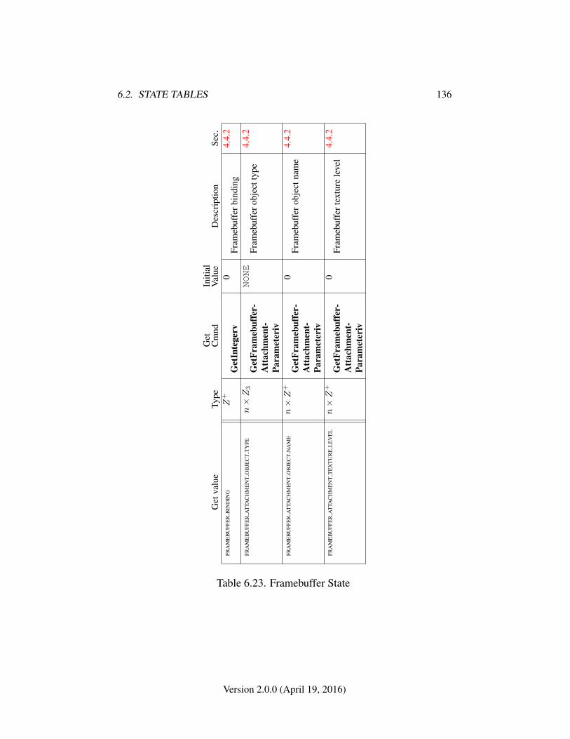
6.2. STATE TABLES 136
Get
valu
eTy
peG
etC
mnd
Initi
alV
alue
Des
crip
tion
Sec.
FRA
ME
BU
FFE
RB
IND
ING
Z+
Get
Inte
gerv
0Fr
ameb
uffe
rbin
ding
4.4.
2
FRA
ME
BU
FFE
RA
TTA
CH
ME
NT
OB
JEC
TT
YPE
n×Z3
Get
Fram
ebuf
fer-
Att
achm
ent-
Para
met
eriv
NONE
Fram
ebuf
fero
bjec
ttyp
e4.
4.2
FRA
ME
BU
FFE
RA
TTA
CH
ME
NT
OB
JEC
TN
AM
En×Z
+
Get
Fram
ebuf
fer-
Att
achm
ent-
Para
met
eriv
0Fr
ameb
uffe
rob
ject
nam
e4.
4.2
FRA
ME
BU
FFE
RA
TTA
CH
ME
NT
TE
XT
UR
EL
EV
EL
n×Z
+
Get
Fram
ebuf
fer-
Att
achm
ent-
Para
met
eriv
0Fr
ameb
uffe
rtex
ture
leve
l4.
4.2
Table 6.23. Framebuffer State
Version 2.0.0 (April 19, 2016)
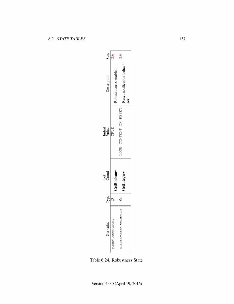
6.2. STATE TABLES 137
Get
valu
eTy
peG
etC
mnd
Initi
alV
alue
Des
crip
tion
Sec.
CO
NT
EX
TR
OB
UST
AC
CE
SSB
Get
Boo
lean
vTRUE
Rob
usta
cces
sen
able
d2.
6
GL
RE
SET
NO
TIF
ICA
TIO
NST
RA
TE
GY
Z2
Get
Inte
gerv
LOSE_CONTEXT_ON_RESET
Res
etno
tifica
tion
beha
v-io
r
2.6
Table 6.24. Robustness State
Version 2.0.0 (April 19, 2016)
Appendix A
Invariance
The OpenGL SC specification is not pixel exact. It therefore does not guarantee anexact match between images produced by different GL implementations. However,the specification does specify exact matches, in some cases, for images producedby the same implementation. The purpose of this appendix is to identify and pro-vide justification for those cases that require exact matches.
A.1 Repeatability
The obvious and most fundamental case is repeated issuance of a series of GL com-mands. For any given GL and framebuffer state vector, and for any GL command,the resulting GL and framebuffer state must be identical whenever the command isexecuted on that initial GL and framebuffer state.
One purpose of repeatability is avoidance of visual artifacts when a double-buffered scene is redrawn. If rendering is not repeatable, swapping between twobuffers rendered with the same command sequence may result in visible changesin the image. Such false motion is distracting to the viewer. Another reason forrepeatability is testability.
Repeatability, while important, is a weak requirement. Given only repeata-bility as a requirement, two scenes rendered with one (small) polygon changedin position might differ at every pixel. Such a difference, while within the lawof repeatability, is certainly not within its spirit. Additional invariance rules aredesirable to ensure useful operation.
138
A.2. MULTI-PASS ALGORITHMS 139
A.2 Multi-pass Algorithms
Invariance is necessary for a whole set of useful multi-pass algorithms. Such al-gorithms render multiple times, each time with a different GL mode vector, toeventually produce a result in the framebuffer. Examples of these algorithms in-clude:
• “Erasing” a primitive from the framebuffer by redrawing it in a differentcolor.
• Using stencil operations to compute capping planes.
On the other hand, invariance rules can greatly increase the complexity of high-performance implementations of the GL. Even the weak repeatability requirementsignificantly constrains a parallel implementation of the GL. Because GL imple-mentations are required to implement ALL GL capabilities, not just a convenientsubset, those that utilize hardware acceleration are expected to alternate betweenhardware and software modules based on the current GL mode vector. A stronginvariance requirement forces the behavior of the hardware and software modulesto be identical, something that may be very difficult to achieve (for example, if thehardware does floating-point operations with different precision than the software).
What is desired is a compromise that results in many compliant, high-performance implementations, and in many software vendors choosing to port toOpenGL SC .
A.3 Invariance Rules
For a given instantiation of an OpenGL rendering context:
Rule 1 For any given GL and framebuffer state vector, and for any given GL com-mand, the resulting GL and framebuffer state must be identical each time the com-mand is executed on that initial GL and framebuffer state.
Rule 2 Changes to the following state values have no side effects (the use of anyother state value is not affected by the change):
Required:
• Framebuffer contents (all bitplanes)
• Scissor parameters (other than enable)
• Writemasks (color, depth, stencil)
Version 2.0.0 (April 19, 2016)
A.4. WHAT ALL THIS MEANS 140
• Clear values (color, depth, stencil)
Strongly suggested:
• Stencil parameters (other than enable)
• Depth test parameters (other than enable)
• Blend parameters (other than enable)
• Pixel storage
• Polygon offset parameters (other than enables, and except as they affectthe depth values of fragments)
Corollary 1 Fragment generation is invariant with respect to the state valuesmarked with • in Rule 2.
Rule 3 The arithmetic of each per-fragment operation is invariant except with re-spect to parameters that directly control it (the parameters that control the depthtest, for instance, are the depth test enable and the depth comparison function).
A.4 What All This Means
Hardware accelerated GL implementations are expected to default to software op-eration when some GL state vectors are encountered. Even the weak repeatabilityrequirement means, for example, that OpenGL SC implementations cannot applyhysteresis to this swap, but must instead guarantee that a given mode vector im-plies that a subsequent command always is executed in either the hardware or thesoftware machine.
The stronger invariance rules constrain when the switch from hardware to soft-ware rendering can occur, given that the software and hardware renderers are notpixel identical. For example, the switch can be made when blending is enabled ordisabled, but it should not be made when a change is made to the blending param-eters.
Because floating point values may be represented using different formats indifferent renderers (hardware and software), many OpenGL SC state values maychange subtly when renderers are swapped. This is the type of state value changethat Rule 1 seeks to avoid.
Version 2.0.0 (April 19, 2016)
Appendix B
Corollaries
The following observations are derived from the body and the other appendixes ofthe specification. Absence of an observation from this list in no way impugns itsveracity.
1. The error semantics of upward compatible OpenGL SC revisions maychange. Otherwise, only additions can be made to upward compatible re-visions.
2. GL query commands are not required to satisfy the semantics of the Flushor the Finish commands. All that is required is that the queried state be con-sistent with complete execution of all previously executed GL commands.
3. Application specified point size and line width must be returned as specifiedwhen queried. Implementation-dependent clamping affects the values onlywhile they are in use.
4. The mask specified as the third argument to StencilFunc affects the operandsof the stencil comparison function, but has no direct effect on the update ofthe stencil buffer. The mask specified by StencilMask has no effect on thestencil comparison function; it limits the effect of the update of the stencilbuffer.
5. There is no atomicity requirement for OpenGL SC rendering commands,even at the fragment level.
6. Because rasterization of non-antialiased polygons is point sampled, poly-gons that have no area generate no fragments when they are rasterized, andthe fragments generated by the rasterization of “narrow” polygons may notform a continuous array.
141

142
7. As a consequence of the chosen model, left- or right-handedness of any of thecoordinate systems is not an implementation consideration, and applicationsusing OpenGL-SC may choose to operate in either way,
8. (No pixel dropouts or duplicates.) Let two polygons share an identical edge(that is, there exist vertices A and B of an edge of one polygon, and verticesC and D of an edge of the other polygon, and the coordinates of vertex A(resp. B) are identical to those of vertex C (resp. D), and the state of thecoordinate transformations is identical when A, B, C, and D are specified).Then, when the fragments produced by rasterization of both polygons aretaken together, each fragment intersecting the interior of the shared edge isproduced exactly once.
9. Dithering algorithms may be different for different components. In particu-lar, alpha may be dithered differently from red, green, or blue, and an imple-mentation may choose to not dither alpha at all.
Version 2.0.0 (April 19, 2016)
Appendix C
Shared Objects and MultipleContexts
This appendix describes special considerations for objects shared between multipleOpenGL SC contexts, including how changes to shared objects are propagatedbetween contexts. 1
The share list of a context is the group of all contexts which share objects withthat context.
C.1 Sharing Contexts Between Different Versions ofOpenGL SC
Implementations may or may not allow sharing between contexts implementingdifferent OpenGL SC versions. However, implementation-dependent behaviormay result when aspects and/or behaviors of such shared objects do not apply to,and/or are not described by more than one version.
C.2 Sharing Objects Between Different Contexts inOpenGL SC
Implementations may choose to support sharing of any object such as vertex bufferobjects, program objects, renderbuffer objects, and texture objects (except for thetexture objects named zero).
1This appendix was entirely rewritten in version 2.0.25 of the OpenGL ES Specification, to matchthe same appendix in the OpenGL 4.1 Specification and add caveats regarding different treatment offramebuffer objects in OpenGL SC .
143
C.3. PROPAGATING CHANGES TO OBJECTS 144
C.3 Propagating Changes to Objects
GL objects contain two types of information, data and state. Collectively theseare referred to below as the contents of an object. For the purposes of propagatingchanges to object contents as described below, data and state are treated consis-tently.
Data is information the GL implementation does not have to inspect, and doesnot have an operational effect. Currently, data consists of:
• Pixels in the framebuffer.
• The contents of textures and renderbuffers.
• The contents of buffer objects.
State determines the configuration of the rendering pipeline and the driver doeshave to inspect it.
In hardware-accelerated GL implementations, state typically lives in GPU reg-isters, while data typically lives in GPU memory.
When the contents of an object T are changed, such changes are not alwaysimmediately visible, and do not always immediately affect GL operations involvingthat object. Changes may occur via any of the following means:
• State-setting commands, such as TexParameter.
• Data-setting commands, such as TexSubImage* or BufferSubData.
• Data-setting through rendering to attached renderbuffers.
C.3.1 Determining Completion of Changes to an object
The contents of an object T are considered to have been changed once a commandsuch as described in section C.3 has completed. Completion of a command maybe determined by calling Finish.
C.3.2 Definitions
In the remainder of this section, the following terminology is used:
• An object T is directly attached to the current context if it has been bound toone of the context binding points. Examples include but are not limited tobound textures and current programs.
Version 2.0.0 (April 19, 2016)
C.3. PROPAGATING CHANGES TO OBJECTS 145
• T is indirectly attached to the current context if it is attached to another objectC, referred to as a container object, and C is itself directly or indirectlyattached. Examples include but are not limited to renderbuffers or texturesattached to framebuffers and shaders attached to programs.
• An object T which is directly attached to the current context may be re-attached by re-binding T at the same bind point. An object T which is indi-rectly attached to the current context may be re-attached by re-attaching thecontainer object C to which T is attached.
Corollary: re-binding C to the current context re-attaches C and its hierarchyof contained objects.
C.3.3 Rules
The following rules must be obeyed by all GL implementations:
Rule 1 If the contents of an object T are changed in the current context while T isdirectly or indirectly attached, then all operations on T will use the new contentsin the current context.
Note: The intent of this rule is to address changes in a single context only. Themulti-context case is handled by the other rules.
Note: “Updates” via rendering are treated consistently with updates via GLcommands.
Rule 2 While a container object C is bound, any changes made to the contents ofC’s attachments in the current context are guaranteed to be seen. To guaranteeseeing changes made in another context to objects attached to C, such changesmust be completed in that other context (see section C.3.1) prior to C being bound.Changes made in another context but not determined to have completed as de-scribed in section C.3.1, or after C is bound in the current context, are not guaran-teed to be seen.
Rule 3 Changes to the contents of shared objects are not automatically propa-gated between contexts. If the contents of a shared object T are changed in acontext other than the current context, and T is already directly or indirectly at-tached to the current context, any operations on the current context involving T viathose attachments are not guaranteed to use its new contents.
Rule 4 If the contents of an object T are changed in a context other than the cur-rent context, T must be attached or re-attached to at least one binding point in the
Version 2.0.0 (April 19, 2016)

C.3. PROPAGATING CHANGES TO OBJECTS 146
current context in order to guarantee that the new contents of T are visible in thecurrent context.
Note: “Attached or re-attached” means either attaching an object to a bindingpoint it wasn’t already attached to, or attaching an object again to a binding pointit was already attached.
Example: If a texture image is bound to multiple texture bind points and thetexture is changed in another context, re-binding the texture at any one of the tex-ture bind points is sufficient to cause the changes to be visible at all texture bindpoints.
Version 2.0.0 (April 19, 2016)
Appendix D
Version 2.0
OpenGL SC 2.0 is not compatible with the prior version (OpenGL SC 1.0). It intro-duces programmable vertex and fragment shaders, but removes the fixed-functionpipeline.
147
Appendix E
Extension Registry, Header Files,and Extension NamingConventions
E.1 Extension Registry
Many extensions to the OpenGL SC API have been defined by vendors, groups ofvendors, and the Khronos OpenGL SC Working Group. In order not to compromisethe readability of the OpenGL SC Specification, such extensions are not integratedinto the core language; instead, they are made available online in the OpenGL SCExtension Registry.
Extensions are documented as changes to a particular version of the Specifica-tion. The Registry is available on the World Wide Web at URL
http://www.khronos.org/registry/glsc/
E.2 Header Files
OpenGL SC 2.0 provides two header files.<GLSC2/glsc2.h> defines APIs for core OpenGL SC 2.0.<GLSC2/glsc2ext.h> defines APIs for all registered OGLSC, EXT, and
vendor extensions compatible with OpenGL SC 2.0 (some extensions are onlycompatible with OpenGL SC 1.x).
148
E.3. OGLSC EXTENSIONS 149
E.3 OGLSC Extensions
OpenGL SC extensions that have been approved by the Khronos OpenGL SCWorking Group are summarized in this section. These extensions are not requiredto be supported by a conformant OpenGL SC implementation, but are expected tobe widely available; they define functionality that is likely to move into the requiredfeature set in a future version of the Specification.
E.3.1 Naming Conventions
To distinguish OGLSC extensions from core OpenGL SC features and fromvendor-specific extensions, the following naming conventions are used:
• A unique name string of the form "GL_OGLSC_name" is associated witheach extension. If the extension is supported by an implementation, thisstring will be present in the EXTENSIONS string.
• All functions defined by the extension will have names of the form Func-tionOGLSC
• All enumerants defined by the extension will have names of the formNAME_OGLSC.
E.4 Vendor and EXT Extensions
Vendor extensions (not approved by Khronos) use the same naming conventionsas OGLSC extensions, but with a different tag replacing OGLSC. The followingpolicies should always be followed when defining and shipping vendor extensions:
• A vendor tag will be assigned to a vendor on request to the Khronos Regis-trar, if one is not already defined.
• This vendor tag must be used consistently in the extension name stringsand the corresponding function and enumerant names for extensions definedsolely by that vendor.
• Numeric values assigned to enumerants must follow the guidelines describedin the OpenGL SC Extension Registry. Reserved blocks of enumerant valueswill be assigned to vendors on request, following the process defined in theRegistry.
Version 2.0.0 (April 19, 2016)

E.4. VENDOR AND EXT EXTENSIONS 150
• The reserved tag EXT may be used instead of a company-specific tag ifmultiple vendors agree to ship the same vendor extension.
• If a vendor decides to ship another vendor’s extension at a later date, theoriginal extension name and vendor tag should still be used, unless bothvendors agree to promote that extension to an EXT.
An implementation exporting extension strings, or supporting function or enu-merant names not following these naming guidelines, is not conformant.
Khronos strongly encourages vendors to submit full extension specificationsto the OpenGL SC Extension Registry for publication, once they have finisheddefining the functionality in an extension. Extension writing guidelines, templates,and other process documents are also found in the Registry.
Version 2.0.0 (April 19, 2016)
Appendix F
GLSL Limitations
F.1 Overview
OpenGL SC 2.0 implementations are not required to support the full GLSL ES1.00 specification. This section lists the features which are not fully supportedin OpenGL SC 2.0. Features not listed in this section must be supported in theirentirety. Within the GLSL ES specification, implementations are permitted to im-plement features beyond the minimal described in this section, without the use ofan extension.
F.2 Length of Shader Executable
The maximum length of the shader executable is implementation specific.
F.3 Usage of Temporary Variables
The maximum number of variables is implementation specific.
F.4 Control Flow
In general, control flow is limited to forward branching and to loops where themaximum number of iterations can easily be determined at compile time. For-ward branching is allowed, both for constant and non-constant conditions. There-fore if-then, if-then-else, break and continue statements are permitted.Backward branching is only permitted for constant iteration loops as defined below.In the following section, loop indices are defined as all the non-constant variables
151
F.5. INDEXING OF ARRAYS, VECTORS AND MATRICES 152
appearing in the branch condition expression in a loop. for loops are supportedbut with the following restrictions:
• There is one loop index.
• The loop index has type int or float.
• The for statement has the form:
for ( init-declaration ; condition ; expression ) statement
• init-declaration has the form:
type-specifier identifier = constant-expression
Consequently the loop variable cannot be a global variable.
• condition has the form
loop_index relational_operator constant_expression
where relational operator is one of: >, >=, <, <=, ==, or ! =
• for_header has one of the following forms:
loop_index++loop_index--loop_index += constant_expressionloop_index -= constant_expression
• Within the body of the loop, the loop index is not statically assigned to noris it used as the argument to a function out or inout parameter.
Support for while and do-while is not mandated.
F.5 Indexing of Arrays, Vectors and Matrices
Definition:constant-index-expressions are a superset of constant-expressions.Constant-index-expressions can include loop indices as defined in section F.4.The following are constant-index-expressions:
• Constant expressions
• Loop indices as defined in section F.4
• Expressions composed of both of the above
When used as an index, a constant-index-expression must have integraltype.
Version 2.0.0 (April 19, 2016)
F.5. INDEXING OF ARRAYS, VECTORS AND MATRICES 153
Uniforms (excluding samplers)
In the vertex shader, support for all forms of array indexing is man-dated. In the fragment shader, support for indexing is only mandated forconstant-index-expressions.
Samplers
GLSL ES 1.00 supports both arrays of samplers and arrays of structures whichcontain samplers. In both these cases, for OpenGL SC 2.0, support for indexingwith a constant-index-expression is mandated but support for indexing withother values is not mandated.
Attributes
Support for indexing of matrices and vectors withconstant-index-expressions is mandated. Support for indexing of matri-ces and vectors with other values is not mandated. Attribute arrays are disallowedby the specification.
Varyings
Support for indexing with a constant-index-expression is mandated. Sup-port for indexing with other values is not mandated.
Variables
Support for indexing with a constant-index-expression is mandated. Sup-port for indexing with other values is not mandated.
Constants
Support for indexing of matricesand vectors with constant-index-expression is mandated. Support for in-dexing of matrices and vectors with other values is not mandated. Constant arrays
Version 2.0.0 (April 19, 2016)
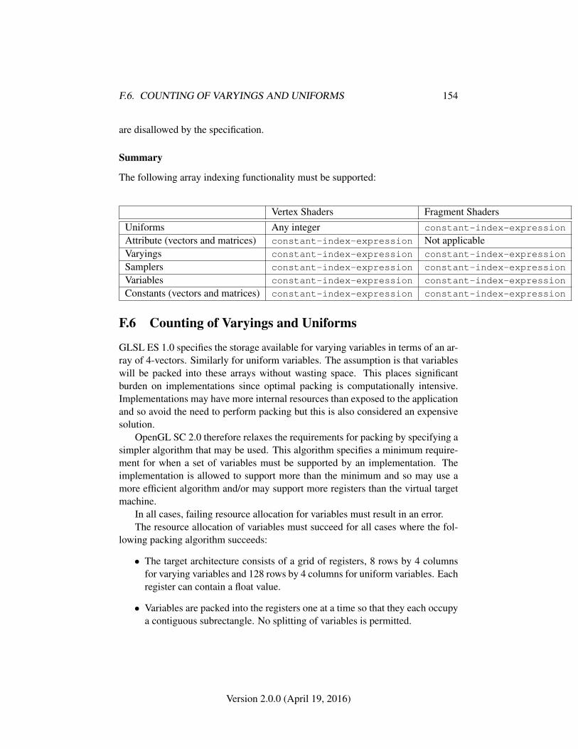
F.6. COUNTING OF VARYINGS AND UNIFORMS 154
are disallowed by the specification.
Summary
The following array indexing functionality must be supported:
Vertex Shaders Fragment ShadersUniforms Any integer constant-index-expression
Attribute (vectors and matrices) constant-index-expression Not applicableVaryings constant-index-expression constant-index-expression
Samplers constant-index-expression constant-index-expression
Variables constant-index-expression constant-index-expression
Constants (vectors and matrices) constant-index-expression constant-index-expression
F.6 Counting of Varyings and Uniforms
GLSL ES 1.0 specifies the storage available for varying variables in terms of an ar-ray of 4-vectors. Similarly for uniform variables. The assumption is that variableswill be packed into these arrays without wasting space. This places significantburden on implementations since optimal packing is computationally intensive.Implementations may have more internal resources than exposed to the applicationand so avoid the need to perform packing but this is also considered an expensivesolution.
OpenGL SC 2.0 therefore relaxes the requirements for packing by specifying asimpler algorithm that may be used. This algorithm specifies a minimum require-ment for when a set of variables must be supported by an implementation. Theimplementation is allowed to support more than the minimum and so may use amore efficient algorithm and/or may support more registers than the virtual targetmachine.
In all cases, failing resource allocation for variables must result in an error.The resource allocation of variables must succeed for all cases where the fol-
lowing packing algorithm succeeds:
• The target architecture consists of a grid of registers, 8 rows by 4 columnsfor varying variables and 128 rows by 4 columns for uniform variables. Eachregister can contain a float value.
• Variables are packed into the registers one at a time so that they each occupya contiguous subrectangle. No splitting of variables is permitted.
Version 2.0.0 (April 19, 2016)

F.6. COUNTING OF VARYINGS AND UNIFORMS 155
• The orientation of variables is fixed. Vectors always occupy registers in asingle row. Elements of an array must be in different rows. E.g. vec4 willalways occupy one row; float[8] will occupy one column. Since it is notpermitted to split a variable, large arrays e.g. for varyings, float[16] willalways fail with this algorithm.
• Variables consume only the minimum space required with the exception thatmat2 occupies 2 complete rows. This is to allow implementations more flex-ibility in how variables are stored.
• Arrays of size N are assumed to take N times the size of the base type.
• Variables are packed in the following order:
1. Arrays of mat4 and mat4
2. Arrays of mat2 and mat2 (since they occupy full rows)
3. Arrays of vec4 and vec4
4. Arrays of mat3 and mat3
5. Arrays of vec3 and vec3
6. Arrays of vec2 and vec2
7. Arrays of float and float
• For each of the above types, the arrays are processed in order of size, largestfirst. Arrays of size 1 and the base type are considered equivalent. In the caseof varyings, the first type to be packed (successfully) is mat4[2] followed bymat4, mat2[2], mat2, vec4[8], ve4[7],...vec4[1], vec4, mat3[2], mat3 and soon. The last variables to be packed will be float (and float[1]).
• For 2,3 and 4 component variables packing is started using the 1st columnof the 1st row. Variables are then allocated to successive rows, aligning themto the 1st column.
• For 2 component variables, when there are no spare rows, the strategy isswitched to using the highest numbered row and the lowest numbered col-umn where the variable will fit. (In practice, this means they will be alignedto the x or z component.) Packing of any further 3 or 4 component variableswill fail at this point.
• 1 component variables (i.e. floats and arrays of floats) have their own pack-ing rule. They are packed in order of size, largest first. Each variable isplaced in the column that leaves the least amount of space in the column and
Version 2.0.0 (April 19, 2016)
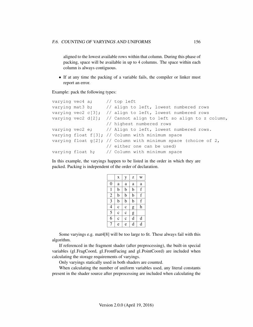
F.6. COUNTING OF VARYINGS AND UNIFORMS 156
aligned to the lowest available rows within that column. During this phase ofpacking, space will be available in up to 4 columns. The space within eachcolumn is always contiguous.
• If at any time the packing of a variable fails, the compiler or linker mustreport an error.
Example: pack the following types:
varying vec4 a; // top leftvarying mat3 b; // align to left, lowest numbered rowsvarying vec2 c[3]; // align to left, lowest numbered rowsvarying vec2 d[2]; // Cannot align to left so align to z column,
// highest numbered rowsvarying vec2 e; // Align to left, lowest numbered rows.varying float f[3]; // Column with minimum spacevarying float g[2]; // Column with minimum space (choice of 2,
// either one can be used)varying float h; // Column with minimum space
In this example, the varyings happen to be listed in the order in which they arepacked. Packing is independent of the order of declaration.
x y z w0 a a a a1 b b b f2 b b b f3 b b b f4 c c g h5 c c g6 c c d d7 e e d d
Some varyings e.g. mat4[8] will be too large to fit. These always fail with thisalgorithm.
If referenced in the fragment shader (after preprocessing), the built-in specialvariables (gl FragCoord, gl FrontFacing and gl PointCoord) are included whencalculating the storage requirements of varyings.
Only varyings statically used in both shaders are counted.When calculating the number of uniform variables used, any literal constants
present in the shader source after preprocessing are included when calculating the
Version 2.0.0 (April 19, 2016)
F.7. SHADER PARAMETERS 157
storage requirements. Multiple instances of identical constants should count mul-tiple times.
Part of the storage may be reserved by an implementation for its own use e.g.for computation of transcendental functions. This reduces the number of uniformsavailable to the shader. The size of this reduction is hardware specific.
F.7 Shader Parameters
The following are the minimum values that must be supported by an OpenGL SC2.0 implementation:
const mediump int gl_MaxVertexAttribs = 8;const mediump int gl_MaxVertexUniformVectors = 128;const mediump int gl_MaxVaryingVectors = 8;const mediump int gl_MaxVertexTextureImageUnits = 0;const mediump int gl_MaxCombinedTextureImageUnits = 8;const mediump int gl_MaxTextureImageUnits = 8;const mediump int gl_MaxFragmentUniformVectors = 16;const mediump int gl_MaxDrawBuffers = 1;
Version 2.0.0 (April 19, 2016)
Appendix G
Packaging andAcknowledgements
G.1 Header Files and Libraries
The Khronos Implementer’s Guidelines, a separate document linked from theKhronos Extension Registry at
https://www.khronos.org/registry/
describes recommended and required practice for implementing OpenGL SC, including links to the header file defining interfaces for the OpenGL SCAPI (glsc2.h) as well as a separate headers (glsc2platform.h andkhrplatform.h) referenced by OpenGL SC .
Preprocessor tokens GL_SC_VERSION_n_m, where n and m are the major andminor version numbers as described in section 6.1.4, are included in glsc2.h.These tokens indicate the OpenGL SC versions supported at compile-time.
G.2 Acknowledgements
The OpenGL SC 2.0 specification is the result of the contributions of many people,representing a cross section of the embedded computer industry. It builds uponthe existing OpenGL ES 2.0 specification which contains a list of OpenGL ES 2.0acknowledgements. The acknowledgements here represent the contributions madeto transform OpenGL ES 2.0 into OpenGL SC 2.0. Following is a partial list ofthe contributors, including the company that they represented at the time of theircontribution:
158
G.3. DOCUMENT HISTORY 159
Bob Schulman, AMD
Alastair Murray, Codeplay
Illya Rudkin, Codeplay
Aidan Fabius, Core Avionic & Industrial Inc.
John Lawless, Core Avionics & Industrial Inc.
Tom Malnar, Core Avionics & Industrial Inc.
John McCormick, Core Avionics & Industrial Inc.
Greg Szober, Core Avionics & Industrial Inc.
Steve Viggers, Core Avionics & Industrial Inc.
Ken Wenger, Core Avionics & Industrial Inc.
Steve Ramm, Imagination Technologies
Andy Southwell, Imagination Technologies
Erik Noreke, Independent (working group chair)
Nakhoon Baek, Kyungpook National University
Hwanyong Lee, Kyungpook National University
Mark Rivers, Mentor Graphics
Paul Jennings, Presagis
Cary Ashby, Rockwell Collins
Doug Singkoffer, Rockwell Collins
Levi Van Ort, Rockwell Collins
Anand Balagopalakrishnan, Texas Instruments
Ajay Jayaraj, Texas Instruments
G.3 Document History
G.3.1 Version 2.0.0, April 19, 2016
Initial revision of the full specification, based on OpenGL ES 2.0.25.
Version 2.0.0 (April 19, 2016)
Index
ACTIVE TEXTURE, 59, 72, 109ActiveTexture, 33, 59, 59ALIASED POINT SIZE RANGE, 44ALPHA, 85, 133ALWAYS, 81, 82, 123ARRAY BUFFER, 24–27, 109ARRAY BUFFER BINDING, 26
BACK, 50, 81, 88, 118BindBuffer, 24, 24, 27BindFramebuffer, 94, 94, 103BindRenderbuffer, 96, 96BindTexture, 33, 59, 71, 71, 72BLEND, 83BlendColor, 85BlendEquation, 83, 83BlendEquationSeparate, 83, 83BlendFunc, 84, 84BlendFuncSeparate, 84, 84BLUE, 133break, 151BUFFER SIZE, 24, 26BUFFER USAGE, 24, 26BufferData, 25, 25, 27BufferSubData, 26, 27, 144bvec2, 32BYTE, 22
CCW, 50, 118CheckFramebufferStatus, 102, 103,
103, 105CLAMP TO EDGE, 64, 65, 74
Clear, 89, 89, 90ClearColor, 89ClearDepthf, 89ClearStencil, 89COLOR ATTACHMENT0, 77, 91, 95,
98, 102, 110COLOR BUFFER BIT, 89, 90ColorMask, 88, 88, 105COMPRESSED TEXTURE FOR-
MATS, 62CompressedTexSubImage2D, 59, 62,
63, 68condition, 152constant-expressions, 152constant-index-expression, 152–154constant-index-expressions, 152, 153CONSTANT ALPHA, 85CONSTANT COLOR, 85CONTEXT LOST, 15–17continue, 151CreateProgram, 28CULL FACE, 50CullFace, 50, 50, 52CURRENT VERTEX ATTRIB, 112,
113
DECR, 81DECR WRAP, 81DEPTH ATTACHMENT, 77, 95, 98,
102, 110DEPTH BUFFER BIT, 89, 90DEPTH COMPONENT16, 101
160
INDEX 161
DEPTH TEST, 82DepthFunc, 82DepthMask, 88, 88, 105DepthRangef, 38, 109Disable, 50, 52, 79, 80, 82, 83, 86DisableVertexAttribArray, 23, 112DITHER, 86do-while, 152DONT CARE, 107, 129DrawArrays, 19, 23, 23, 26, 27, 29, 104DrawRangeElements, 19, 23, 23, 26,
27, 29, 104DST ALPHA, 85DST COLOR, 85DYNAMIC DRAW, 24, 25
ELEMENT ARRAY BUFFER, 27, 109Enable, 50, 52, 79, 80, 82, 83, 86, 108EnableVertexAttribArray, 22, 112EQUAL, 81, 82EXTENSIONS, 111, 112, 149
FALSE, 32, 36, 80, 121false, 74FASTEST, 107Finish, 106, 106, 141, 144FLOAT, 22, 24, 115float, 29, 152Flush, 106, 141for, 152for header, 152FRAMEBUFFER, 79, 93, 94, 98, 103,
105, 110FRAMEBUFFER ATTACHMENT -
OBJECT NAME, 98, 99, 102,110
FRAMEBUFFER ATTACHMENT -OBJECT TYPE, 98, 99, 101,102, 110
FRAMEBUFFER ATTACHMENT -TEXTURE LEVEL, 69, 70,99, 100, 110
FRAMEBUFFER BINDING, 69, 91,94, 98, 104, 105
FRAMEBUFFER COMPLETE, 103,105
FRAMEBUFFER INCOMPLETE AT-TACHMENT, 102
FRAMEBUFFER INCOMPLETE DI-MENSIONS, 102
FRAMEBUFFER INCOMPLETE -MISSING ATTACHMENT,102
FRAMEBUFFER UNDEFINED, 102FRAMEBUFFER UNSUPPORTED,
102, 103FramebufferRenderbuffer, 97, 98, 103,
105FramebufferTexture2D, 98, 99, 103,
105FRONT, 50, 81, 88FRONT AND BACK, 50, 81, 88FrontFace, 50, 50, 74FUNC ADD, 83, 84, 86, 124FUNC REVERSE SUBTRACT, 83, 84FUNC SUBTRACT, 83, 84
GenBuffers, 24, 25, 25GENERATE MIPMAP HINT, 107GenerateMipmap, 70, 70, 107GenFramebuffers, 94, 95, 95GenRenderBuffers, 96GenRenderbuffers, 96, 97, 97GenTextures, 71, 72, 72GEQUAL, 81, 82Get, 39, 108GetAttribLocation, 30, 30GetBooleanv, 80, 108, 113GetBufferParameteriv, 109
Version 2.0.0 (April 19, 2016)
INDEX 162
GetError, 14, 14, 16GetFloatv, 10, 80, 108, 113GetFramebufferAttachmentParameteriv,
105, 109, 110GetGraphicsResetStatus, 15, 16GetIntegerv, 43, 91, 97, 108, 113GetnUniform*, 113GetnUniformfv, 113GetnUniformiv, 113GetProgramiv, 112GetRenderbufferParameteriv, 97, 110,
111GetString, 111, 112GetTexParameter, 59, 109GetUniformLocation, 31, 33GetVertexAttribfv, 112GetVertexAttribiv, 112GetVertexAttribPointerv, 113gl FragColor, 75gl FragCoord, 74gl FragData, 75gl FragData[0], 75gl FrontFacing, 74gl PointCoord, 44gl PointSize, 44gl Position, 34, 37GL SC VERSION n m, 158GREATER, 81, 82GREEN, 133GUILTY CONTEXT RESET, 16
Hint, 106
if-then, 151if-then-else, 151IMPLEMENTATION COLOR -
READ FORMAT, 91IMPLEMENTATION COLOR -
READ TYPE, 91INCR, 81
INCR WRAP, 81INNOCENT CONTEXT RESET, 16inout, 152INT, 92int, 152INVALID ENUM, 15, 17, 59, 60, 103,
105, 110, 111INVALID FRAMEBUFFER OPERA-
TION, 17, 104, 105INVALID OPERATION, 17, 24, 25,
29–33, 56, 59–61, 63, 71, 91,94, 96–99, 105, 109–111, 113
INVALID VALUE, 15, 17, 21–23, 26,32, 39, 45, 53, 60–63, 79, 89,97, 99, 105, 112, 113
INVERT, 81IsEnabled, 79, 108, 113
KEEP, 81, 82, 123
LEQUAL, 81, 82LESS, 81, 82, 123level zero array, 60LINE LOOP, 19LINE STRIP, 19LINEAR, 64, 67–69, 71, 73, 74, 100LINEAR MIPMAP LINEAR, 64, 68–
70, 100LINEAR MIPMAP NEAREST, 64, 68,
70, 100LINES, 19LineWidth, 45LOSE CONTEXT ON RESET, 16,
137
m, 158mat2, 30mat3, 30mat4, 30MAX COMBINED TEXTURE IM-
AGE UNITS, 34, 59, 109
Version 2.0.0 (April 19, 2016)
INDEX 163
MAX FRAGMENT UNIFORM VEC-TORS, 73
MAX RENDERBUFFER SIZE, 97,105
MAX TEXTURE IMAGE UNITS, 34,58, 74
MAX TEXTURE SIZE, 60MAX VARYING VECTORS, 34MAX VERTEX ATTRIBS, 21–24, 30,
112, 113MAX VERTEX TEXTURE IMAGE -
UNITS, 34, 58MAX VERTEX UNIFORM VEC-
TORS, 30MIRRORED REPEAT, 64, 65
n, 158NEAREST, 64, 66, 68, 69, 73, 74, 100NEAREST MIPMAP LINEAR, 64,
68–71, 100NEAREST MIPMAP NEAREST, 64,
68, 69, 100NEVER, 81, 82NICEST, 107NO ERROR, 14–16, 134NO RESET NOTIFICATION, 16NONE, 101, 110, 136NOTEQUAL, 81, 82NULL, 24, 114, 115NUM COMPRESSED TEXTURE -
FORMATS, 62NUM PROGRAM BINARY FOR-
MATS, 29
ONE, 85, 86, 124ONE MINUS CONSTANT ALPHA,
85ONE MINUS CONSTANT COLOR,
85ONE MINUS DST ALPHA, 85
ONE MINUS DST COLOR, 85ONE MINUS SRC ALPHA, 85ONE MINUS SRC COLOR, 85out, 152OUT OF MEMORY, 15, 17, 26, 97,
105
PACK ALIGNMENT, 91, 126PixelStore, 54, 91, 93PixelStorei, 53, 53POINTS, 19POLYGON OFFSET FILL, 52PolygonOffset, 51PROGRAM BINARY FORMATS, 29ProgramBinary, 28, 28
ReadnPixels, 53, 55, 90, 91, 91, 94, 104RED, 55, 56, 74, 92, 133RENDERBUFFER, 96–98, 110RENDERBUFFER ALPHA SIZE, 111RENDERBUFFER BINDING, 97,
105, 110RENDERBUFFER BLUE SIZE, 111RENDERBUFFER DEPTH SIZE, 111RENDERBUFFER GREEN SIZE, 111RENDERBUFFER HEIGHT, 111RENDERBUFFER INTERNAL FOR-
MAT, 111RENDERBUFFER RED SIZE, 111RENDERBUFFER STENCIL SIZE,
111RENDERBUFFER WIDTH, 111RenderbufferStorage, 97, 97, 105RENDERER, 111REPEAT, 64, 66, 67, 71, 121REPLACE, 81RESET NOTIFICATION STRATEGY,
16RG, 55, 56, 74RGB, 55–58, 74, 85
Version 2.0.0 (April 19, 2016)
INDEX 164
RGB565, 101RGB5 A1, 101RGBA, 55–58, 74, 91RGBA4, 101, 135
SAMPLE ALPHA TO COVERAGE,79
SAMPLE BUFFERS, 43, 44, 48, 52,79, 86–88, 95
SAMPLE COVERAGE, 79, 80SAMPLE COVERAGE INVERT, 79,
80SAMPLE COVERAGE VALUE, 79,
80SampleCoverage, 80sampler2D, 33SAMPLES, 43, 95Scissor, 79SCISSOR TEST, 79SHADING LANGUAGE VERSION,
111SHORT, 22SRC ALPHA, 85SRC ALPHA SATURATE, 85SRC COLOR, 85STATIC DRAW, 24, 25, 116STENCIL ATTACHMENT, 77, 95, 98,
102, 110STENCIL BUFFER BIT, 89, 90STENCIL INDEX8, 101STENCIL TEST, 80StencilFunc, 80, 81, 82, 141StencilFuncSeparate, 80, 81, 82StencilMask, 88, 88, 105, 141StencilMaskSeparate, 88, 88, 105StencilOp, 80, 81, 82StencilOpSeparate, 80, 81, 82STREAM DRAW, 24, 25
TexParameter, 63, 144
TexStorage2D, 59, 59–62TexSubImage*, 144TexSubImage2D, 53–55, 59, 61, 61, 62,
68, 90, 92TEXTURE, 99, 110TEXTUREi, 59TEXTURE0, 59, 122TEXTURE 2D, 33, 61, 63, 70–72, 99,
109, 120TEXTURE IMMUTABLE FORMAT,
59TEXTURE MAG FILTER, 64, 69, 71TEXTURE MIN FILTER, 64, 66–69,
71, 100TEXTURE WRAP S, 63, 64, 66, 67TEXTURE WRAP T, 63, 64, 67TRIANGLE FAN, 20TRIANGLE STRIP, 19TRIANGLES, 20TRUE, 22, 32, 59, 80, 88, 137true, 74
Uniform, 11, 31Uniform*, 31–33Uniform*f{v}, 31, 32Uniform*i{v}, 31, 32Uniform1f, 11Uniform1i, 11Uniform1i{v}, 32, 33Uniform1iv, 32Uniform2f, 11Uniform2f{v}, 32Uniform2i, 11Uniform2i{v}, 32Uniform3f, 11Uniform3i, 11Uniform4f, 10, 11Uniform4f{v}, 32Uniform4i, 11Uniform4i{v}, 32
Version 2.0.0 (April 19, 2016)
INDEX 165
UniformMatrix*, 32UniformMatrix3fv, 32UniformMatrix{234}fv, 31, 32UNKNOWN CONTEXT RESET, 16UNPACK ALIGNMENT, 54, 56, 126UNSIGNED BYTE, 22, 55, 56, 91, 92UNSIGNED SHORT, 22, 23, 57UNSIGNED SHORT 4 4 4 4, 55–57,
92UNSIGNED SHORT 5 5 5 1, 55–57,
92UNSIGNED SHORT 5 6 5, 55–57, 92UseProgram, 29, 29, 34, 36
vec2, 29vec3, 29vec4, 29, 32VENDOR, 111VERSION, 111, 112VERTEX ATTRIB ARRAY -
BUFFER BINDING, 26, 112VERTEX ATTRIB ARRAY EN-
ABLED, 112VERTEX ATTRIB ARRAY NOR-
MALIZED, 112VERTEX ATTRIB ARRAY -
POINTER, 113VERTEX ATTRIB ARRAY SIZE, 112VERTEX ATTRIB ARRAY STRIDE,
112VERTEX ATTRIB ARRAY TYPE,
112VertexAttrib, 21VertexAttrib*, 21, 29VertexAttrib1*, 21VertexAttrib2*, 21VertexAttrib3*, 21VertexAttrib4*, 21VertexAttribPointer, 22, 22, 26, 113Viewport, 38
while, 152
ZERO, 81, 85, 86, 124
Version 2.0.0 (April 19, 2016)