Embed Size (px)
Citation preview
1
Open-Guideway Personal Rapid Transit Station Options Peter J. Muller, P.E.*
*President, PRT Consulting, Inc., 1340 Deerpath Trail, Ste 200, Franktown, CO 80116 www.prtconsulting.com
Abstract Open guideway personal rapid transit (PRT) systems are inherently more flexible than captive-bogey systems or elevated systems and, thus, lend themselves to an almost infinite variety of station configurations. This paper explores alternative station layouts for open-guideway PRT systems. The station layouts studied include configurations resulting from consideration of various combinations of such variables as, in-line station; off-line station; single bay; multiple bay; in-line bay; off-line bay; elevated; at grade; below grade; one-way guideway; two-way (shuttle) guideway; access from one side of transportation pod (T-Pod); access from both sides of T-Pod; in building; attached to building; elaborate; simplistic. The wide variety of stations presented provides potential solutions for PRT stations in many different applications.
Introduction and Basic Philosophy Captive bogey PRT systems, such as those being developed by Vectus and Skyweb Express, show little variation in station design. The stations are always off-line, and the bays are always arranged in line with each other. This lack of variation probably results from the intended relative high capacity of these systems and their inability to accommodate tight radii. Open guideway systems such as those being developed by ULTra and 2getthere on the other hand, can accommodate tight radii and are probably better suited to handling low capacity situations. The flexibility of open guideway PRT systems invites a wide variety of station design, meeting a wide range of capacity requirements and customer/passenger needs.
This paper discusses various station configurations suitable for a range of applications. Drawings are provided, depicting some preferred layouts. The drawings are mostly not to scale and are focused on the stations themselves, so required items, such as guideway safety fencing/railing and adequate acceleration/deceleration lengths, are often not shown or incorrectly depicted. This paper is focused on layout and operational considerations, and architectural aspects are not addressed. All of the stations shown could be rendered appealing, through appropriate architectural means.
Two important factors drive the philosophy behind the station designs, shown herein. These are, the desire to keep stations simple with low costs, and the desire to keep platforms as close as reasonable, to the elevation of the users.
Transfers and mode changes are the Achilles heel of transit. The worst involve climbing steps, while lifting luggage, combined with unknown transportation arrival and travel times. The best involve walk/roll on/off, such as, transitioning onto or off a moving sidewalk. The closer PRT station design comes to achieving the latter, the better.
2
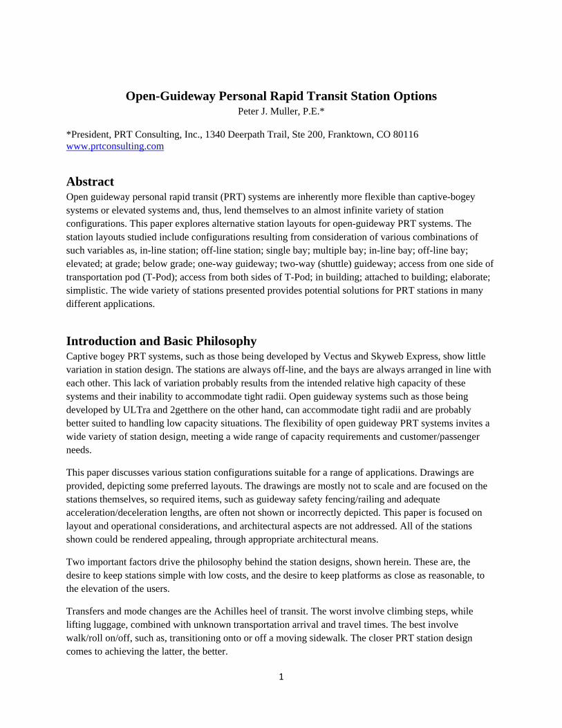
Figure 1. Morgantown PRT station. Note the lack of station doors.
Stations that are at a different level to the general pedestrian level suffer from two problems. They are difficult to find, and they require vertical circulation means that add to capital and maintenance costs and reduce safety. The elevated people mover, in Concourse A at Detroit Metropolitan Wayne County Airport, can easily be missed, altogether, by passengers unfamiliar with the airport. The Washington Metro’s underground stations are difficult to spot and are served by elevators and escalators, 20% of which are usually out of service.
Station Basics Stations designed for use in the USA should meet the requirements of the Americans with Disabilities Act. At-grade station platforms should include wheelchair ramps, down or up, to the surrounding pedestrian grade. Elevated or underground stations should include elevators.
Since common PRT design includes very short wait time (often less than one minute), the need to provide an enclosure, or even a roof for passenger comfort, is minimal. However, a roof will often be advisable, to protect parked T-Pods and station equipment from the weather and sunlight-induced heat loads, in particular. If such a roof is provided, it would make sense to extend it over the passenger platform too.
Station doors are considered unnecessary from a safety standpoint – particularly for open guideway systems having no third rail. They may be desirable for preventing conditioned air from escaping down the guideway. People and animals should be constrained from accessing at-grade guideways by safety fencing/railing. The fencing/railing should be far enough from the vehicle path to avoid potential pinch points. This is particularly important in a station where an arm, extending over a railing, could be pinched by a slow-moving T-Pod. The fencing/railing can have an opening opposite the door position of a parked T-Pod. Floor texturing, floor color, signage and cctv monitoring has been 100% successfully used, for over 30 years, to prevent accidents on the Morgantown PRT system (which has a third rail), as depicted in Figure 1.
3
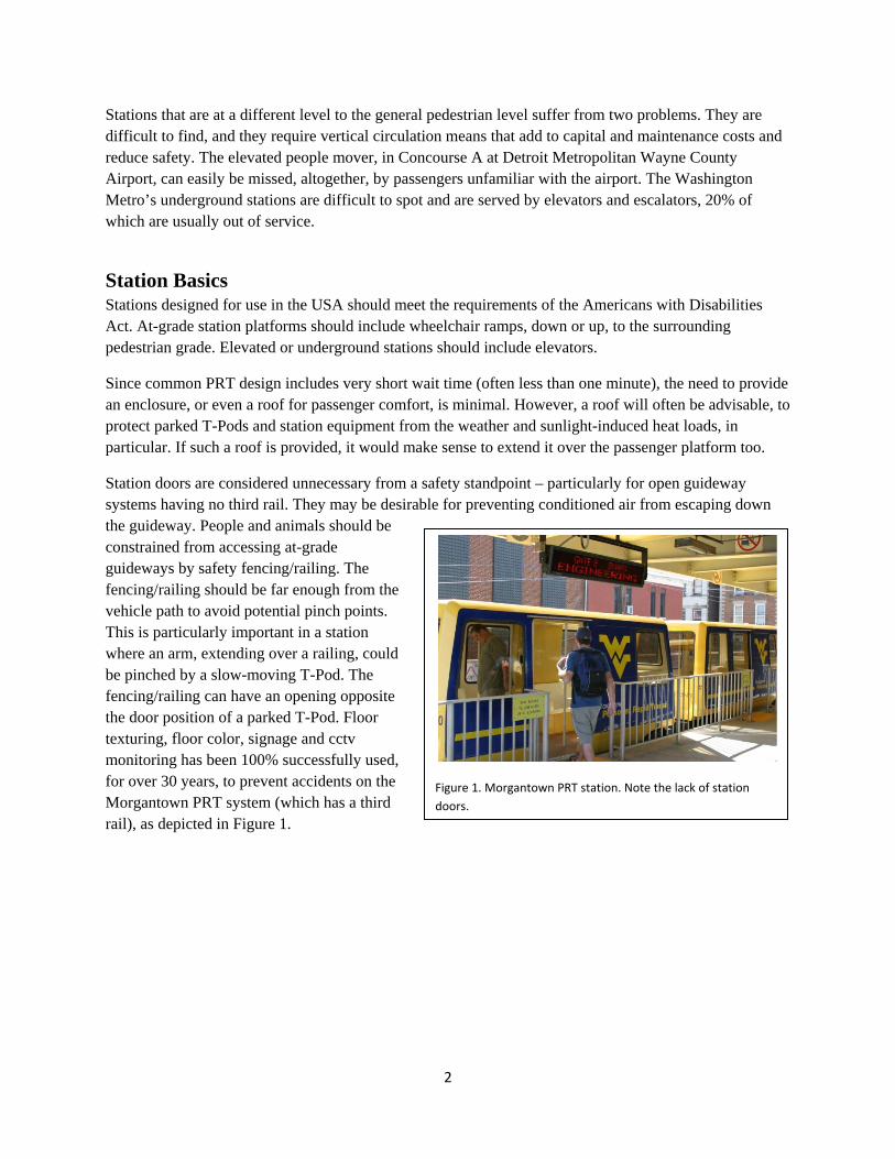
Figure 2. Off‐line station.
In-Line Stations In-line stations, on a main guideway, are contrary to the basic PRT philosophy, but might be appropriate in very low capacity situations. A more common use, of an in-line station, could be where one or more stations are on a loop, off the main guideway, that is necessary but has low demand. This whole loop could then be treated like a long station bypass.
Off-Line Stations
A typical PRT off-line station layout is shown in Figure 2. The station is on a bypass guideway separate to the main guideway. Depending on the control system, station bypass guideways may include areas set aside to stage arriving and/or departing T-Pods. T-Pod bays/access points are indicated on this illustration and a number of others by gaps in the side wall.
The station allows T-Pods, on the main guideway, to continue on their way, without slowing for station operations by other T-Pods. The station bypass guideway shown is diagrammatic. The bypass guideway is used for acceleration and deceleration, to and from main guideway speed, and its length has to be designed accordingly.
In-Line Station Bays The station bays, in Figure 2, are in line with each other. This has the advantage of simplicity, but the disadvantage of a delayed T-Pod blocking following vehicles. This is the typical configuration for captive-bogey system stations. When there are numerous bays in this configuration, the T-pods usually leave in platoons. This means that the dwell (in-station) time of each T-Pod is often dictated by the dwell time of the slowest T-pod, in the station in front of that T-Pod. Another drawback of this layout is that a problem in the station, in peak periods, can fairly quickly lead to the bays and the arrival staging area filling up. At this point, the station has to stop accepting T-Pods and, any T-Pods destined to it, must be either held in their departure stations, sent to an intermediate staging destination, or waived off (made to go on past the station exit and loop around for another attempt). Whether to choose an intermediate staging destination, or a waive-off, is typically dependent on the type of control system being used.
4
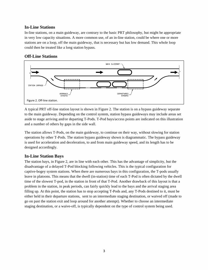
Figure 3. Saw‐tooth off‐line station bays.
Figure 4. Off‐line station bays.
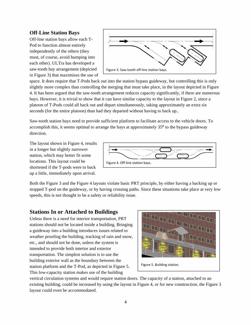
Figure 5. Building station.
Off-Line Station Bays Off-line station bays allow each T-Pod to function almost entirely independently of the others (they must, of course, avoid bumping into each other). ULTra has developed a saw-tooth bay arrangement (depicted in Figure 3) that maximizes the use of space. It does require that T-Pods back out into the station bypass guideway, but controlling this is only slightly more complex than controlling the merging that must take place, in the layout depicted in Figure 4. It has been argued that the saw-tooth arrangement reduces capacity significantly, if there are numerous bays. However, it is trivial to show that it can have similar capacity to the layout in Figure 2, since a platoon of T-Pods could all back out and depart simultaneously, taking approximately an extra six seconds (for the entire platoon) than had they departed without having to back up..
Saw-tooth station bays need to provide sufficient platform to facilitate access to the vehicle doors. To accomplish this, it seems optimal to arrange the bays at approximately 35⁰ to the bypass guideway direction.
The layout shown in Figure 4, results in a longer but slightly narrower station, which may better fit some locations. This layout could be shortened if the T-pods were to back up a little, immediately upon arrival.
Both the Figure 3 and the Figure 4 layouts violate basic PRT principle, by either having a backing up or stopped T-pod on the guideway, or by having crossing paths. Since these situations take place at very low speeds, this is not thought to be a safety or reliability issue.
Stations In or Attached to Buildings Unless there is a need for interior transportation, PRT stations should not be located inside a building. Bringing a guideway into a building introduces issues related to weather proofing the building, tracking of rain and snow, etc., and should not be done, unless the system is intended to provide both interior and exterior transportation. The simplest solution is to use the building exterior wall as the boundary between the station platform and the T-Pod, as depicted in Figure 5. This low-capacity station makes use of the building vertical circulation systems and would require station doors. The capacity of a station, attached to an existing building, could be increased by using the layout in Figure 4, or for new construction, the Figure 3 layout could even be accommodated.
5
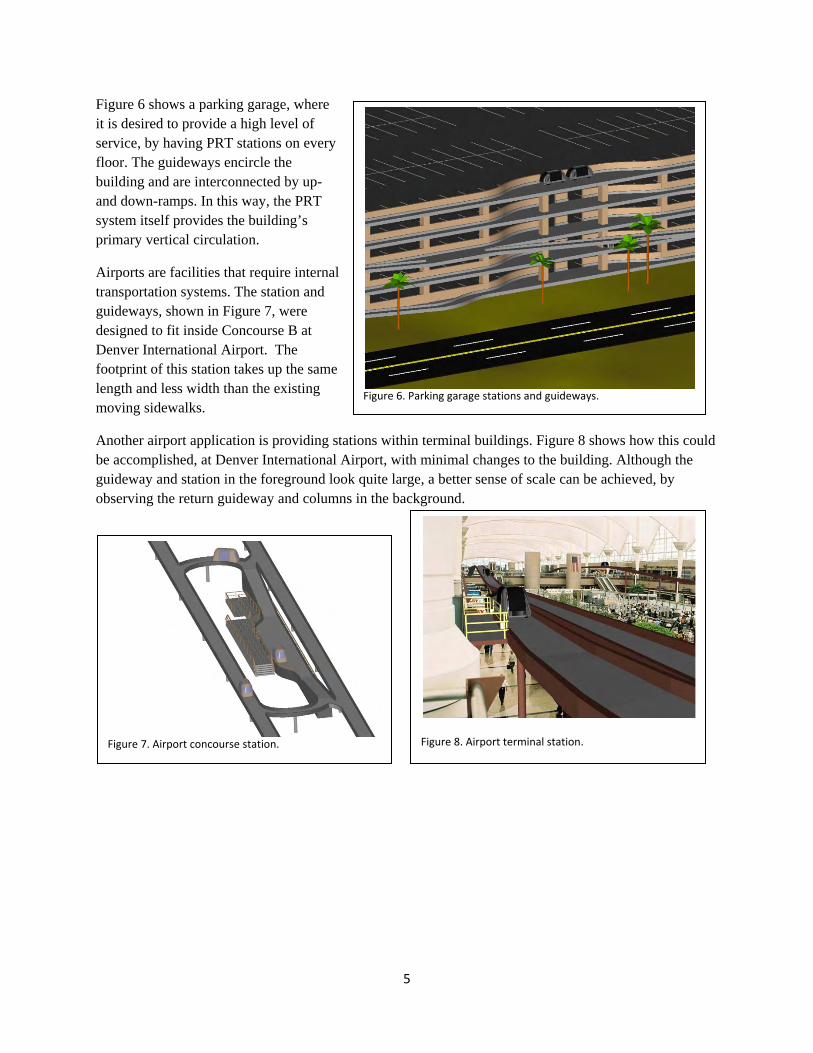
Figure 6. Parking garage stations and guideways.
Figure 7. Airport concourse station. Figure 8. Airport terminal station.
Figure 6 shows a parking garage, where it is desired to provide a high level of service, by having PRT stations on every floor. The guideways encircle the building and are interconnected by up- and down-ramps. In this way, the PRT system itself provides the building’s primary vertical circulation.
Airports are facilities that require internal transportation systems. The station and guideways, shown in Figure 7, were designed to fit inside Concourse B at Denver International Airport. The footprint of this station takes up the same length and less width than the existing moving sidewalks.
Another airport application is providing stations within terminal buildings. Figure 8 shows how this could be accomplished, at Denver International Airport, with minimal changes to the building. Although the guideway and station in the foreground look quite large, a better sense of scale can be achieved, by observing the return guideway and columns in the background.

6
Figure 9. Urban elevated guideway station. Figure 10. Close up – urban elevated guideway station.
Urban Stations
Elevated Guideway
As stated previously, it is recommended that stations be at grade whenever possible, even if the guideway is elevated. One problem with doing this is that, bringing the guideway all the way down to grade takes up a significant amount of space. A compromise arrangement is shown in Figures 7, 9 and 10, where the guideway is brought down to a station platform, raised about four feet (1.2m) above grade. This compromise results in the station taking the space of approximately 8 parking stalls. This will not be a problem, if the PRT system reduces the need for parking. The station is provided with stairs and a wheelchair ramp for pedestrian and handicap access. This arrangement requires slightly longer station bypass guideways, since gravity opposes both acceleration and deceleration.
Below-Grade Guideway While stations for below-grade guideways can be provided completely underground, as for a subway, it is recommended that they be brought close to grade, for the same reasons mentioned before. Figure 11 depicts a station, adjacent to a three-lane road, with the platform depressed about 1.2 m (four feet). The station, plus sidewalk, fits in the width previously assigned to parking and sidewalk, plus about 1 m (three feet). Approximately six parking stalls must be sacrificed to the station, plus an area about 43 m (140 feet) by 1 m (3 feet) on the building side of the station. Greater length (and, possibly, width) would be needed for additional bays.
7
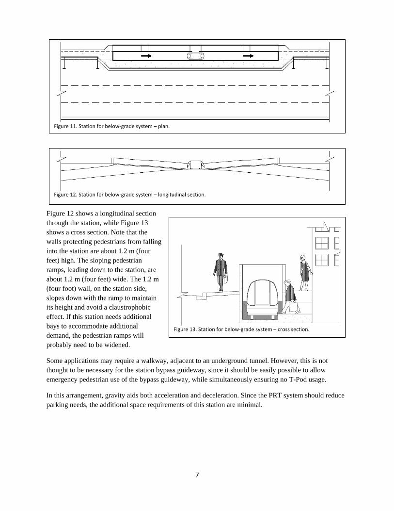
Figure 11. Station for below‐grade system – plan.
Figure 12. Station for below‐grade system – longitudinal section.
Figure 13. Station for below‐grade system – cross section.
Figure 12 shows a longitudinal section through the station, while Figure 13 shows a cross section. Note that the walls protecting pedestrians from falling into the station are about 1.2 m (four feet) high. The sloping pedestrian ramps, leading down to the station, are about 1.2 m (four feet) wide. The 1.2 m (four foot) wall, on the station side, slopes down with the ramp to maintain its height and avoid a claustrophobic effect. If this station needs additional bays to accommodate additional demand, the pedestrian ramps will probably need to be widened.
Some applications may require a walkway, adjacent to an underground tunnel. However, this is not thought to be necessary for the station bypass guideway, since it should be easily possible to allow emergency pedestrian use of the bypass guideway, while simultaneously ensuring no T-Pod usage.
In this arrangement, gravity aids both acceleration and deceleration. Since the PRT system should reduce parking needs, the additional space requirements of this station are minimal.
8
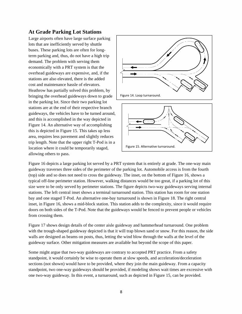
Figure 14. Loop turnaround.
Figure 15. Alternative turnaround.
At Grade Parking Lot Stations Large airports often have large surface parking lots that are inefficiently served by shuttle buses. These parking lots are often for long-term parking and, thus, do not have a high trip demand. The problem with serving them economically with a PRT system is that the overhead guideways are expensive, and, if the stations are also elevated, there is the added cost and maintenance hassle of elevators. Heathrow has partially solved this problem, by bringing the overhead guideways down to grade in the parking lot. Since their two parking lot stations are at the end of their respective branch guideways, the vehicles have to be turned around, and this is accomplished in the way depicted in Figure 14. An alternative way of accomplishing this is depicted in Figure 15. This takes up less area, requires less pavement and slightly reduces trip length. Note that the upper right T-Pod is in a location where it could be temporarily staged, allowing others to pass.
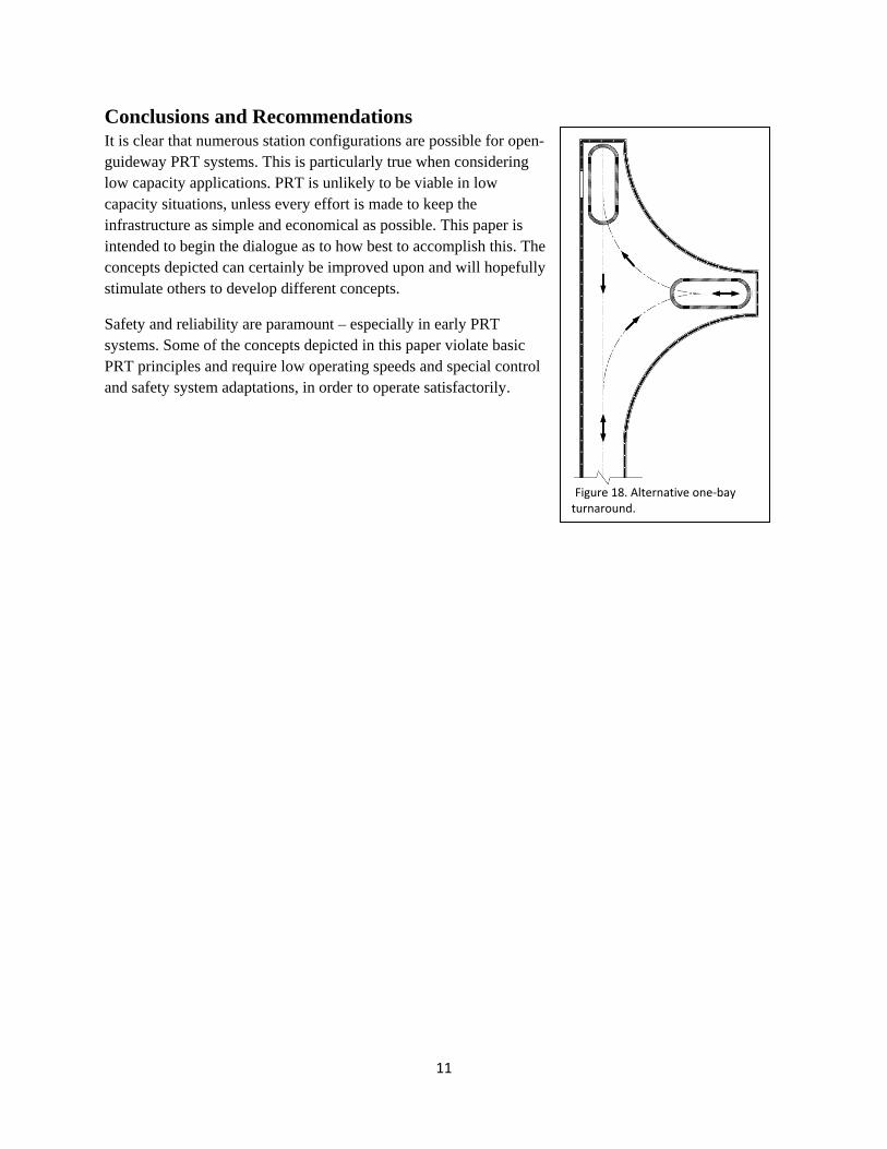
Figure 16 depicts a large parking lot served by a PRT system that is entirely at grade. The one-way main guideway traverses three sides of the perimeter of the parking lot. Automobile access is from the fourth (top) side and so does not need to cross the guideway. The inset, on the bottom of Figure 16, shows a typical off-line perimeter station. However, walking distances would be too great, if a parking lot of this size were to be only served by perimeter stations. The figure depicts two-way guideways serving internal stations. The left central inset shows a terminal turnaround station. This station has room for one station bay and one staged T-Pod. An alternative one-bay turnaround is shown in Figure 18. The right central inset, in Figure 16, shows a mid-block station. This station adds to the complexity, since it would require doors on both sides of the T-Pod. Note that the guideways would be fenced to prevent people or vehicles from crossing them.
Figure 17 shows design details of the center aisle guideway and hammerhead turnaround. One problem with the trough-shaped guideway depicted is that it will trap blown sand or snow. For this reason, the side walls are designed as beams on posts, thus, letting the wind blow through the walls at the level of the guideway surface. Other mitigation measures are available but beyond the scope of this paper.
Some might argue that two-way guideways are contrary to accepted PRT practice. From a safety standpoint, it would certainly be wise to operate them at slow speeds, and acceleration/deceleration sections (not shown) would have to be provided, where they join the main guideway. From a capacity standpoint, two one-way guideways should be provided, if modeling shows wait times are excessive with one two-way guideway. In this event, a turnaround, such as depicted in Figure 15, can be provided.

9
Figure 16. Large parking lot PRT system.

10
Figure 17. Hammerhead turnaround details.
11
Figure 18. Alternative one‐bay turnaround.
Conclusions and Recommendations It is clear that numerous station configurations are possible for open-guideway PRT systems. This is particularly true when considering low capacity applications. PRT is unlikely to be viable in low capacity situations, unless every effort is made to keep the infrastructure as simple and economical as possible. This paper is intended to begin the dialogue as to how best to accomplish this. The concepts depicted can certainly be improved upon and will hopefully stimulate others to develop different concepts.
Safety and reliability are paramount – especially in early PRT systems. Some of the concepts depicted in this paper violate basic PRT principles and require low operating speeds and special control and safety system adaptations, in order to operate satisfactorily.