Embed Size (px)
Citation preview

This is an author-deposited version published in: http://oatao.univ-toulouse.fr/
Eprints ID: 11308
To cite this version: Moschetta, Jean-Marc The aerodynamics of micro air
vehicles: technical challenges and scientific issues. (2014) Internation
Journal of Engineering Systems Modelling and Simulation, vol. 6 (n° 3/4).
pp. 134-148. ISSN 1755-9758
Open Archive Toulouse Archive Ouverte (OATAO) OATAO is an open access repository that collects the work of Toulouse researchers and
makes it freely available over the web where possible.
Any correspondence concerning this service should be sent to the repository
administrator: [email protected]
The aerodynamics of micro air vehicles: technical challenges and scientific issues
Jean-Marc Moschetta
Department Aerodynamics, Energetics and Propulsion,
Institut Supérieur de l’Aéronautique et de l’Espace,
10 Avenue Edouard Belin,
F-31400 Toulouse, France
E-mail: [email protected]
Abstract: Micro air vehicles raise numerous design problems associated to the size reduction:
lower aerodynamic and propulsion efficiencies, higher sensitivity to atmospheric turbulence,
low-density energy of electric propulsion, etc. The paper discusses some of the most important
design issues and analyses the aerodynamic challenges encountered in the field of MAVs.
A number of novel aerodynamic configurations combining rotors and fixed-wing are proposed
and discussed in order to recover efficiency and maneuverability at low speeds.
Keywords: micro air vehicles; MAVs; low-Reynolds aerodynamics; tilt-body; convertible
aircraft; propeller-wing interaction; coaxial rotors.
Reference to this paper should be made as follows: Moschetta, J-M. (2014) ‘The aerodynamics
of micro air vehicles: technical challenges and scientific issues’, Int. J. Engineering Systems
Modelling and Simulation, Vol. 6, Nos. 3/4, pp.134–148.
Biographical notes: Jean-Marc Moschetta is a Professor of Aerodynamics in the Department
Aerodynamics, Energetics and Propulsion at the ‘Institut Supérieur de l’Aéronautique et de
l’Espace’ (ISAE). He graduated from SUPAERO in 1987. He received his PhD in 1991 and
received the Habilitation thesis in 2000. In 1994–1995, he was invited as a Visiting Professor at
Caltech, California. In 2011, he founded the Micro Air Vehicle Research Centre in Toulouse
which now networks nine research laboratories involved in MAV technologies.
1 Introduction
Micro air vehicles (MAVs) also known as micro-drones
may be defined as uninhabited micro aircraft capable of
completing surveillance or recognition missions in outdoor
or indoor environments. Although a lot of attention has been
paid so far to the embedded system which includes sensors,
autopilot and a payload, MAVs have now reached a level of
maturity such that the problem of improving their
aerodynamic performance is now becoming a major
concern. Because of severe Reynolds effect limitations,
designing MAVs cannot just mean downsizing conventional
aircraft. Instead of mimicking nature which actually did not
produce the rotating motion (with few exceptions), it is
rather advisable to consider combinations of rotors
with fixed-wings in order to achieve good aerodynamic
performances and ease of technological development.
2 MAV design issues
Designing MAVs does not revert to scale down
conventional aircraft configurations. In level flight, the lift
equation equates the vehicle weight and the lift force as
21
2mg SV Cz (1)
while mass m and wing surface S vary as L3 and L2
respectively, where L is the vehicle maximum dimension.
Therefore, the flight speed V reduces as
~V L (2)
while Cz remains almost constant. As a consequence, the
Reynolds number Re based on the wing chord varies as
3/2~Re L (3)
which means that the Reynolds number diminishes faster
than the vehicle size. Namely, reducing the vehicle size by a
factor of two leads to a Reynolds reduction by a factor of 3.
Low-Reynolds effects dramatically affect both the
aerodynamic efficiency and the propulsion efficiency as it
will be described in the next section.
In addition to the Reynolds number reduction, MAVs
have to face a greater sensitivity to atmospheric
perturbations. That is also a consequence of the size

reduction although equation (2) tends to damp the effect. As
it is driven by aerodynamic forces which are proportional to
S, the equation of motion is given by
2 2 2 31~ ~
2mx F SV Cz V L L (4)
Provided that mass also reduces as L3, it follows that the
trajectory sensitivity to atmospheric perturbations is not
intrinsically affected by the size reduction. However, since
the vehicle inertia J reduces as L5, it follows that
2 41~
2J M SV LCm L (5)
where refers to some angle (pitch, roll or yaw) which
describes the vehicle attitude. Since J ~ L5, it follows that
1~ L (6)
which indicates that the vehicle attitude around its centre of
gravity will be greatly affected by the size reduction. In
practice, the picture is much more serious since the average
atmospheric perturbations near the ground (typically
2–5 m/s) becomes comparable to the average MAV flight
speed which ultimately means that flying an MAV in
urban environment is like flying a jetliner through a
cumulonimbus cloud.
Another consequence of mass reduction is that thermal
combustion engines fail to offer a practical solution to the
low endurance problem. While the heat produced
in the combustion chamber is proportional to L3, the heat
flux dissipated through its walls only reduces as L2.
Consequently, miniaturising thermal engines will inevitably
lead to poor thermodynamic efficiencies since most of the
heat produced within the combustion chamber will rapidly
evaporates through the walls. Increasing the rotation speed
to compensate for heat losses will not bring a viable solution
either because of limitations on the chamber residence time.
Furthermore, poor pressure tightness and friction increase
are additional problems which also ruin the attractiveness of
thermal combustion engines when reduced in size
(Sher et al., 2009). MAVs designers are therefore left to the
sole choice of electrically powered vehicles which suffer
from a limited specific energy of a maximum value of 200
Wh/kg for a high quality Lithium-polymer battery.
3 Low-Reynolds airfoils
Numerous papers have been published so far on
low-Reynolds airfoils. As reported by McMasters and
Henderson (1980), the low-Reynolds airfoil performance
dramatically decreases below a chord Reynolds number of
the order of 100,000, which is a typical Reynolds number
encountered by a fixed-wing MAV of 15 cm chord flying at
10 m/s. The unfortunate thing is that the flight regime where
MAVs fly is a very critical regime in which it is difficult to
predict whether the boundary layer is going to be laminar or
turbulent. According to Lissaman (1983), the lift-to-drag
ratio of smooth airfoils may decrease more than an order of
magnitude near the critical Reynolds number. That is due to
the fact that, according to Carmichael’s (1981) rule, the
Reynolds number based on the laminar bubble length is
comparable to the Reynolds number based on the wing
chord, which means that the laminar bubble may cover a
significant part of the wing. In order to reduce the influence
of laminar bubbles, some benefit may be obtained from the
use of transition strips or roughness effects to increase the
lift-to-drag ratio in the critical regime.
Figure 1 Typical ‘zigzag’ effect on the Eppler E374 airfoil polar computed at various chord Reynolds numbers
Source: After Shyy (2008)

Figure 2 Comparison of experimental lift-to-drag ratios for different wing airfoils of aspect ratio 1 (see online version for colours)
As reported by Shyy (2008), instead of the familiar
C-shape of high-Reynolds number airfoils, the lift-drag
polar of low Reynolds-number airfoils exhibit a typical
‘zigzag’ pattern which may affect the overall MAV
performance (Figure 1). For instance, the Eppler E374
airfoil at an angle of attack of 2.75° exhibits a long laminar
bubble which extends on the airfoil upper surface and
creates a large drag. When the angle of attack is further
increased, the long bubble suddenly shortens as a
consequence of the Tollmien-Schlichting wave which
triggers transition and an attached turbulent boundary-layer
flow. As a result, the drag is significantly reduced (around
an angle of attack of 7.82°). Finally, when the angle of
attack is further increased, the turbulent boundary layer can
no longer sustain recompression and a massive separation
occurs, with a substantial drag increase.
A final noticeable feature of low-Reynolds airfoils is
that thin cambered airfoils of the WWI airplanes family
appear to outperform thick airfoils such as the DAE21 or the
MH46 low-Reynolds airfoils both in maximum lift
coefficients and in maximum lift-to-drag ratios. Figure 2
illustrates that effect on a series of low-aspect ratio wings
based on different airfoils and tested in a low-speed wind
tunnel at ISAE.
4 Fixed-wing aerodynamics
Because of the chord Reynolds number limitation combined
with drastic wing loadings, fixed-wing MAVs usually
consist of a flying wing with an aspect ratio between 1
and 2. At such low aspect ratios, the effect of airfoil
selection may appear as less important for the overall
aerodynamic performance due to overwhelming 3D effects.
In order to assess the importance of the airfoil selection, a
set of five rectangular wings of aspect ratio 1.6 has been
fabricated using five different airfoils of constant relative
camber (5%) but varying thicknesses ranging from 2% to
10%. The maximum camber location of all five wings is
30% and a 4-digit NACA series definition has been used for
the five wings: NACA 5302, 5304, 5306, 5308 and 5310.
The idea was to avoid mixing the airfoil camber effect with
the thickness effect. All wings where mounted on a
three-strut setup connected to a 3-component balance
measuring lift, drag and pitching moment for angles of
attack ranging from –2.5° to 32.5° with a step of 1°.
Figure 3 illustrates the effect of airfoil thickness at constant
camber on the aerodynamic performance of the rectangular
wing. As expected in the low-Reynolds number regime,
thinner airfoils yield better aerodynamic performances, both
in terms of power coefficient Cz3/2/Cx and in terms of lift-to-
drag ratio. However, stall is slightly delayed when thickness
is increased. At a Reynolds number of 150,000, increasing
thickness does not drastically affect the aerodynamic
performances above 8%. That means in practice that if a
thicker airfoil has been selected in order to accommodate
on-board equipment for instance, there is no interest in
choosing an intermediate value for the thickness.
At a lower wing chord Reynolds number (60,000), the
picture is more subtle to interpret. Thinner airfoils still
display higher aerodynamic performances than thicker ones
but thicker airfoils (e.g., 10%) show very poor performances
with the consequence of the zigzag effect already described
in Section 3. That effect should be taken care of when the
Reynolds number is decreased below 100,000. In that case,
it is important to consider using either very thin airfoils or,
alternatively, thick airfoils with vortex generator or
transition strips.
In view of the stringent mass limitation, MAV designers
generally tend to use the largest possible wing surface
within the maximum size limitation. For a given maximum
vehicle size, that strategy yields a circular wing planform
which aspect ratio is equal to 4/ or approximately 1.273.
However, it has been shown that increasing the aspect ratio
at constant maximum dimension by shrinking the circle into
an ellipse leads to a decrease of the total drag at constant lift
(Figure 4).

Figure 3 Power coefficients as a function of lift-to-drag ratio for five rectangular wings (AR = 1.6) of varying thicknesses (2% to 10%),
wing chord Reynolds number (a) 150,000 and (b) 60,000 (see online version for colours)
(a)
(b)
Source: After Blanc et al. (2008)
Figure 4 Experimental lift-to-drag ratios of different elliptical wing at various aspect ratios
Source: Moschetta and Thipyopas (2007)
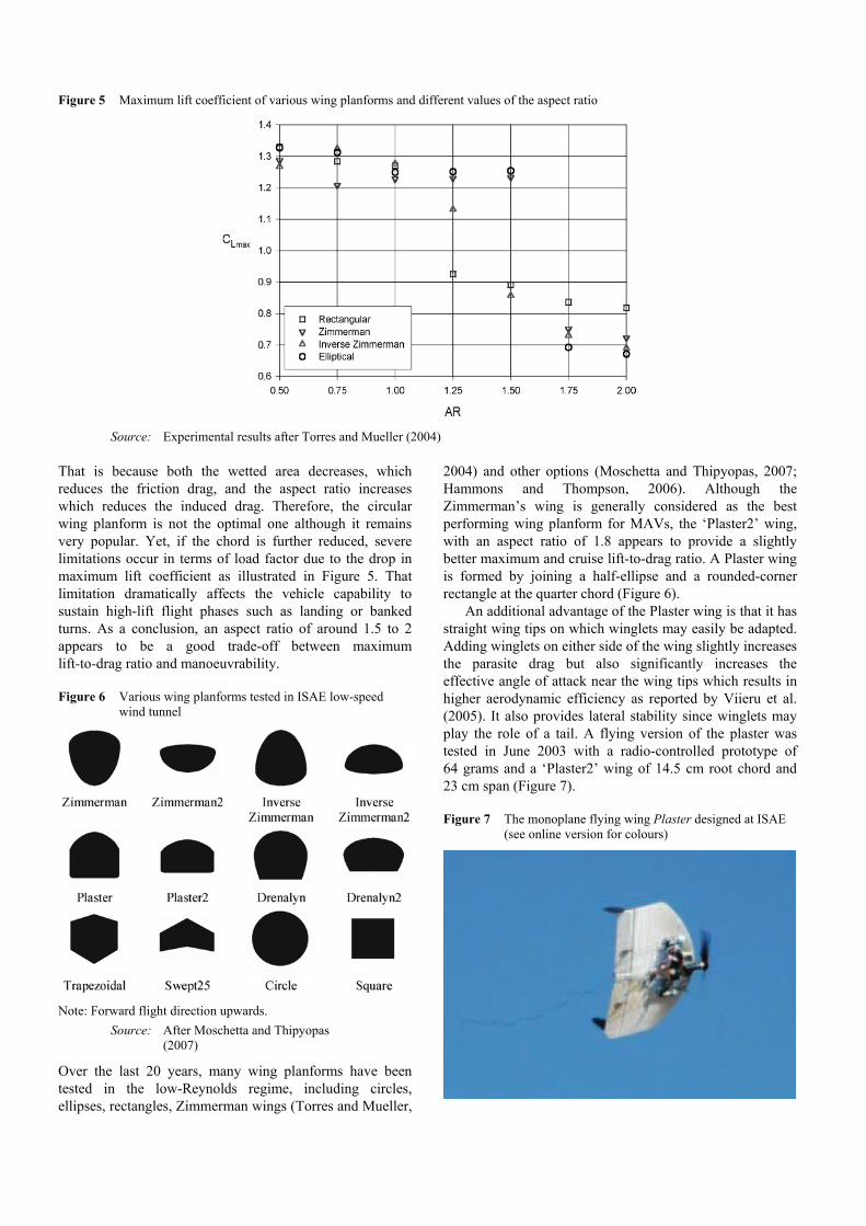
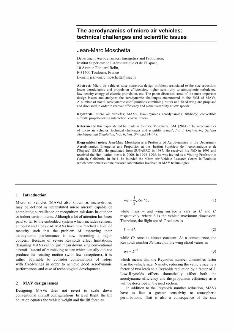
Figure 5 Maximum lift coefficient of various wing planforms and different values of the aspect ratio
Source: Experimental results after Torres and Mueller (2004)
That is because both the wetted area decreases, which
reduces the friction drag, and the aspect ratio increases
which reduces the induced drag. Therefore, the circular
wing planform is not the optimal one although it remains
very popular. Yet, if the chord is further reduced, severe
limitations occur in terms of load factor due to the drop in
maximum lift coefficient as illustrated in Figure 5. That
limitation dramatically affects the vehicle capability to
sustain high-lift flight phases such as landing or banked
turns. As a conclusion, an aspect ratio of around 1.5 to 2
appears to be a good trade-off between maximum
lift-to-drag ratio and manoeuvrability.
Figure 6 Various wing planforms tested in ISAE low-speed
wind tunnel
Note: Forward flight direction upwards.
Source: After Moschetta and Thipyopas
(2007)
Over the last 20 years, many wing planforms have been
tested in the low-Reynolds regime, including circles,
ellipses, rectangles, Zimmerman wings (Torres and Mueller,
2004) and other options (Moschetta and Thipyopas, 2007;
Hammons and Thompson, 2006). Although the
Zimmerman’s wing is generally considered as the best
performing wing planform for MAVs, the ‘Plaster2’ wing,
with an aspect ratio of 1.8 appears to provide a slightly
better maximum and cruise lift-to-drag ratio. A Plaster wing
is formed by joining a half-ellipse and a rounded-corner
rectangle at the quarter chord (Figure 6).
An additional advantage of the Plaster wing is that it has
straight wing tips on which winglets may easily be adapted.
Adding winglets on either side of the wing slightly increases
the parasite drag but also significantly increases the
effective angle of attack near the wing tips which results in
higher aerodynamic efficiency as reported by Viieru et al.
(2005). It also provides lateral stability since winglets may
play the role of a tail. A flying version of the plaster was
tested in June 2003 with a radio-controlled prototype of
64 grams and a ‘Plaster2’ wing of 14.5 cm root chord and
23 cm span (Figure 7).
Figure 7 The monoplane flying wing Plaster designed at ISAE
(see online version for colours)

Figure 8 Winglet effect on the pressure distribution over a square wing using a vortex lattice method (see online version for colours)
Vtot
1.42
1.39
1.36
1.33
1.3
1.27
1.24
1.21
1.18
1.15
1.12
1.09
1.06
1.03
1
Source: After Pardi (2005)
Figure 9 (a) Monoplane MAV ‘Kiool’ in the ISAE S4 low-speed
wind tunnel (b) Oilflow visualisation showing intense
vortical structure on the wing leeward side (see online
version for colours)
(a)
(b)
Both numerical and experimental investigations were
conducted at ISAE to assess the benefit of winglets of
various shapes on a simple rectangular wing. The results
indicate that adding winglets along the wing tips artificially
increases the wing aspect ratio by reducing the effective
induced drag and increases aerodynamic performance in
spite of a slight friction drag penalty (Figure 8).
Figure 10 The Minus-Kiool MAV (57 g, 20 cm) (see online
version for colours)
One of the major aerodynamic problems related to flying
wing is to obtain static longitudinal stability and high
maximum lift at the same time. As an alternative to the
Plaster flying wing which mainly consists of a thin airfoil,
another monoplane wing has been considered in parallel to

provide some room for the on-board electronic equipment.
In order to let the main wing unaffected by control surfaces,
the new idea was to exploit the third dimension by adding
V-shape stabilisers under the wing. The stabilisers would
then provide control in pitch and roll as well as lateral
stability without affecting the aerodynamic efficiency of the
main wing (Figure 9).
Further size reduction was then investigated to fabricate
a flying prototype of less than 60 grams with 20 cm span
(Figure 10). The main wing is made of a rectangular central
part of 14 cm span and 8 cm wing chord. On either side of
that central part, two trapezoidal wings of 6.5 cm width are
connected to the central part with a positive dihedral angle
of 25°. A 30° sweep angle is applied along the side wings
leading edge. That prototype was successfully flown in
2002. It was launched by a portable catapult and equipped
with a miniaturised video camera.
5 Biplane MAVs
Because of the restrictive dimension constraints, the
induced drag of monoplane flying wings represents up to
70% to 80% of the overall drag in cruise conditions. Biplane
configurations provide a classical way to reduce the induced
drag by doubling the monoplane wing surface while
complying with the maximum constraint defined by the
sphere in which the vehicle should fit. The major effect of
biplane wings is roughly to divide the induced drag by a
factor of 2 at the price of a parasite drag increase. In the
case of MAVs where the induced drag plays a major role in
the total drag, it turns out that the drag penalty due to the
additional interference and parasite drag is compensated by
the induced drag reduction if the lift coefficient is greater
that some minimum value. Interference drag is the drag
generated by the aerodynamic interaction between both
wings, while parasite drag includes the additional drag due
to the connecting structure. As illustrated in Table 1, the
biplane configuration yields a substantial increase both of
the maximum lift-to-drag ratio as well as of the cruise
lift-to-drag ratio.
Another advantage of the biplane configuration is that it
can nearly retrieve the maximum lift coefficient produced
by a monoplane wing of aspect ratio 1. As an attempt to
compare two MAV configurations at a given maximum
dimension constraint, a biplane bimotor MAV called Avilent
has been designed and tested in the S4 low-speed wind
tunnel at ISAE [Figure 11(a)]. The Avilent is made of two
wings in tandem configuration which fit into a 51 cm
diameter sphere. Two counter-rotating propellers are located
along the upper wing trailing edge and three control
surfaces are distributed along the lower wing trailing edge
to provide control in pitch and roll. Using counter-rotating
propeller cancel the resulting torque due to moving parts
and allows for a broader blowing effect along the wing
span. The Avilent configuration combines an upper wing
and a lower wing connected by two vertical struts equipped
with counter rotating motors in pusher configuration. Both
wings are based on a S1223 airfoil designed by Selig and
Guglielmo (1997) for the low-Reynolds number regime.
The upper wing is a 48 cm span wing with a 25 cm root
chord and two trapezoidal side wings attached on either side
of a 24 cm span central part of rectangular planform. Both
side wings are 12 cm wide with an 8 cm tip chord.
Figure 11 (a) The Avilent biplane-bimotor MAV configuration
(b) Schematic view of the lower wing (see online
version for colours)
(a)
(b)
Table 1 Experimental aerodynamic performances of monoplane and biplane wings
Wing configuration CDmin k CLmax L/D(cruise) L/D(max)
Monoplane 1 0.055 0.54 1.25 3.89 4.04
Monoplane 2 0.042 0.33 0.59 4.38 5.11
Biplane 2 0.066 0.27 1.06 5.19 5.48
Source: Moschetta and Thipyopas (2007)

Figure 12 Aerodynamic polars of monoplane and biplane MAVs of equal maximum dimension (see online version for colours)
The lower wing is described on Figure 11(b). It consists of a
central part equipped with two side wings with a dihedral
angle of 20° and a 9.5° negative leading edge sweep angle.
The upper wing is tilted with a positive angle of 5° with
respect to the lower wing and the vertical distance between
both wings is equal to 17 cm. As illustrated in Figure 12, the
biplane configuration leads to a much greater maximum lift
coefficient and a higher lift-to-drag ratio when the cruise lift
coefficient is greater than 0.5.
Because the Avilent maximum lift coefficient is twice as
high than the Kiool monoplane configuration (Thipyopas
and Moschetta, 2009), the vehicle can sustain low-speed
flight which is unusual for a fixed-wing configuration. Yet,
because the propeller slipstream only interacts with the
leeward side of the lower wing, vertical flight remained
difficult to achieve. Therefore, following the same idea,
another biplane bimotor configuration was designed in order
to maintain the control surface efficiency even at very low
speed. In order to achieve that, a third horizontal tail was
placed in the propeller slipstream [Figure 13(a)].
In the TYTO concept (Thipyopas et al., 2007), both
upper and lower wings are connected by lateral winglets
which surround the propellers, protecting the airframe and
enhancing the overall vehicle rigidity. The upper wing is a
30 cm span semi-circular wing equipped with two motors
located along the trailing edge in pusher configuration. The
lower wing is described in Figure 13(b). A flying prototype
version controlled by the Paparazzi autopilot developed at
ENAC has been successfully flown in 2007. The MAV,
called TYTO30, is a 30 cm span airframe equipped with a
2-axis video-camera fitted into a ping-pong ball (Figure 14).
Figure 13 (a) A powered wind tunnel model of the TYTO MAV,
rear view (b) Lower wing planform (see online
version for colours)
(a)
(b)
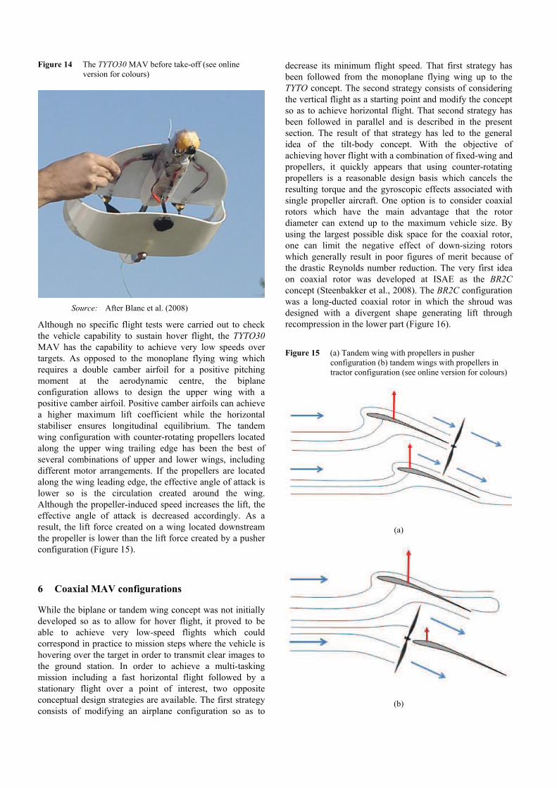
Figure 14 The TYTO30 MAV before take-off (see online
version for colours)
Source: After Blanc et al. (2008)
Although no specific flight tests were carried out to check
the vehicle capability to sustain hover flight, the TYTO30
MAV has the capability to achieve very low speeds over
targets. As opposed to the monoplane flying wing which
requires a double camber airfoil for a positive pitching
moment at the aerodynamic centre, the biplane
configuration allows to design the upper wing with a
positive camber airfoil. Positive camber airfoils can achieve
a higher maximum lift coefficient while the horizontal
stabiliser ensures longitudinal equilibrium. The tandem
wing configuration with counter-rotating propellers located
along the upper wing trailing edge has been the best of
several combinations of upper and lower wings, including
different motor arrangements. If the propellers are located
along the wing leading edge, the effective angle of attack is
lower so is the circulation created around the wing.
Although the propeller-induced speed increases the lift, the
effective angle of attack is decreased accordingly. As a
result, the lift force created on a wing located downstream
the propeller is lower than the lift force created by a pusher
configuration (Figure 15).
6 Coaxial MAV configurations
While the biplane or tandem wing concept was not initially
developed so as to allow for hover flight, it proved to be
able to achieve very low-speed flights which could
correspond in practice to mission steps where the vehicle is
hovering over the target in order to transmit clear images to
the ground station. In order to achieve a multi-tasking
mission including a fast horizontal flight followed by a
stationary flight over a point of interest, two opposite
conceptual design strategies are available. The first strategy
consists of modifying an airplane configuration so as to
decrease its minimum flight speed. That first strategy has
been followed from the monoplane flying wing up to the
TYTO concept. The second strategy consists of considering
the vertical flight as a starting point and modify the concept
so as to achieve horizontal flight. That second strategy has
been followed in parallel and is described in the present
section. The result of that strategy has led to the general
idea of the tilt-body concept. With the objective of
achieving hover flight with a combination of fixed-wing and
propellers, it quickly appears that using counter-rotating
propellers is a reasonable design basis which cancels the
resulting torque and the gyroscopic effects associated with
single propeller aircraft. One option is to consider coaxial
rotors which have the main advantage that the rotor
diameter can extend up to the maximum vehicle size. By
using the largest possible disk space for the coaxial rotor,
one can limit the negative effect of down-sizing rotors
which generally result in poor figures of merit because of
the drastic Reynolds number reduction. The very first idea
on coaxial rotor was developed at ISAE as the BR2C
concept (Steenbakker et al., 2008). The BR2C configuration
was a long-ducted coaxial rotor in which the shroud was
designed with a divergent shape generating lift through
recompression in the lower part (Figure 16).
Figure 15 (a) Tandem wing with propellers in pusher
configuration (b) tandem wings with propellers in
tractor configuration (see online version for colours)
(a)
(b)

Figure 16 The BR2C: a ducted-fan coaxial MAV (see online
version for colours)
Source: Steenbakker et al. (2008)
The main design idea in the BR2C MAV was to compensate
the weight penalty due to the addition of the outer structure
by generating some additional lift so that the total mass
budget was kept constant. In addition, the duct significantly
increases the birotor efficiency because of a reduction in tip
losses. The inlet shape also plays an important role in the
total lift force since the inlet round shape creates a low
pressure zone which further increases the lift (Huo et al.,
2011). Control in pitch and roll was obtained by two flaps
located below the birotor. Although long-ducted birotors are
suitable for indoor missions, they are very sensitive to
crosswind conditions and therefore are unlikely to handle
outdoor flights. As a consequence, a short-ducted birotor
was designed to reduce the lateral surface in crosswind
conditions. The Satoorn MAV was then designed and flown
at ISAE as illustrated in Figure 17.
Figure 17 The Satoorn: a short ducted-fan coaxial MAV
(see online version for colours)
In order to control the Satoorn in pitch and roll, two smaller
rotors were added in the rear part of the vehicle. The
Satoorn was successfully flown outdoors but suffered from
strong nonlinearities due to the aerodynamic interactions
between the main coaxial rotor and the control rotors as
described by Thipyopas et al. (2008, 2010).
7 The tilt-body concept
In order to achieve either translation flight or vertical flight,
different options are available. One is to directly tilt the
rotors or the wing located in the rotor slipstream such as in
the V-22 ‘Osprey’ configuration. In the field of MAVs, the
AVIGLE developed at Aachen University is an example of
such a concept which requires an additional rotor above the
horizontal tail in order to control the pitching moment
(Holsten et al., 2011). Furthermore, it requires a tilting
mechanism in the airframe which leads to a significant
weight penalty. At ISAE, another option has been followed.
It was inspired by the Convair ‘Pogo’ XFY-1 developed in
the 1950s in the USA [Figure 18(a)]. The main idea is to tilt
the entire vehicle to perform transition flight. In horizontal
flight, the vehicle may behave like a regular airplane
while in vertical flight it may hover like a helicopter. A first
tail-sitter mini-UAV called Vertigo was developed and
flown in 2006 at ISAE [Figure 18(b)].
Figure 18 (a) The Convair ‘Pogo’ vs. (b) the mini-UAV
‘Vertigo’ (see online version for colours)
(a) (b)
Source: After Bataille et al. (2009)
The Vertigo was powered by a coaxial rotor located in
tractor position and equipped with two main wings and two
smaller wings in the other direction. Control in pitch, roll
and yaw was obtained by elevators located on all four wings
while the counter-rotating propellers were constantly
blowing onto the control surfaces to maintain an
equilibrium throughout transition between horizontal and
vertical flight (Bataille et al., 2009). A downscaling of the
Vertigo led to the mini-Vertigo developed at ISAE in
collaboration with the University of Arizona (Figure 19).
While the Vertigo wings were made of mere flat plate
airfoils, the mini-Vertigo (30 cm span) was equipped with a
Zimmerman’s wing and radio-controlled through gyro
stabilisation for a total mass of less than 200 grams. It
proved to be very capable of fast forward flight as well as
vertical flight (Shkarayev et al., 2008).

Figure 19 The mini-Vertigo: a coaxial fixed-wing MAV
(see online version for colours)
Source: After Shkarayev et al. (2008)
Because of its exposed rotors in tractor position, the
mini-Vertigo was still very vulnerable to collisions and
crashes. A first attempt to provide a ‘crashproof’ airframe
arouse from the idea of a sphere made of carbon rods. The
Vision was then developed and flown on the occasion of the
MAV07 competition held in Toulouse in 2007 (Figure 20).
Figure 20 The Vision: unducted coaxial fixed-wing MAV
(see online version for colours)
The Vision had a genuine indoor flight capability and
proved to be robust enough so as to be able to roll on the
ground, although not in a controlled mode. It was still
ill-suited to outdoor flights and a modified version of the
Vision, called Vision’Air, was then designed and fabricated
at ISAE (Figure 21). In the Vision’Air concept, several
modifications were applied. First, the hollow shaft
mechanism used in the Vision and the Mini-Vertigo were
replaced by two outrunner brushless motors with propellers
directly attached to the rotating part. Placing the birotor
within the protecting airframe allowed to use any motors
and opened the way for further miniaturisation. Second,
some significant lifting surface was added upstream the
coaxial rotors. The idea was to deflect the flow in front of
the rotors which increased the rotor efficiency. It also
helped to increase the lift during transition instead of
placing all lifting surfaces downstream the coaxial rotors
where the effective angle of attack remains low. Finally, an
airfoil was added onto the lifting surface located
downstream the coaxial rotors so as to improve the
aerodynamic performance in horizontal mode.
Figure 21 Vision’ Air: a compact MAV for transition flight
(see online version for colours)
More recently, another tilt-body prototype has been
designed in view of finding the appropriate trade-off
between aerodynamic performances for horizontal flight
and vertical flight, while keeping in mind the idea of a
protective outer structure. The MAVion was initially
designed to be a reasonably good airplane, capable flying
outdoors and easy to replicate as opposed to more
complicated tail-sitters (Stone, 2008). The main design
guidelines were simplicity and transition flight capacity. In
order to provide a significant aspect ratio (between 1.5
and 2), it was decided to investigate the classical bimotor
flying wing concept (Figure 22).
Figure 22 MAVion: a fixed-wing bimotor MAV for transition
flight (see online version for colours)
Source: Itasse et al. (2011)

The rotation directions for the counter-rotating propellers
were selected so as to artificially increase the aspect ratio by
rotating in the opposite direction of wing vortices. That
choice proved beneficial to start bank turns since, for
instance, when turning right, a greater rotation speed
applied to the left motor would not only produce a right-
turning yaw moment but also a right-turning roll moment.
In 2011, an indoor version was developed and patented with
the use of free carbon wheels which played a protecting role
for the airframe as well as a mean to roll. The MAVion ‘roll
and fly’ was then capable of landing, waiting for a while,
rolling on the ground and remotely taking off without
human interaction. The ‘roll and fly’ concept also
revealed its capability to roll and fly along walls and
ceilings (Figure 23).
A fully-fledged autonomous version has been developed
at ISAE including a video micro-camera or a 24-gram micro
thermal camera for night recognition missions (Itasse et al.,
2011). The propellers were chosen so as to achieve either
forward flight up to 24 m/s or hover flight with a typical
endurance of 15 minutes. In terms of aerodynamic
performance, there are still open problems such as:
1 maintaining hover flight in strong crosswind conditions
2 rolling along a ceiling.
In situation 1, the vehicle will tend to tilt horizontally when
the crosswind gets stronger, hence reducing its projected
area. Ongoing developments include the capability to switch
to a strong wind mode in which the MAVion could hold its
attitude sideways with respect to the lateral wind. A
collective pitch mechanism is also an option that is currently
under investigation in order to adapt the blade pitch to either
airplane or helicopter mode. Situation 2 may become
difficult when the rotors are very close to the ceiling
because the incoming flow is drastically constrained by the
wall boundary condition. Increasing the wheel diameter
may improve unstable behaviours in rolling phases but that
would also involve adding mass to the vehicle.
Figure 23 The MAVion ‘Roll & Fly’ climbing along a vertical
wall (see online version for colours)
Source: Itasse et al. (2011)
Figure 24 The lift distribution over the SPOC wing and its optimised horizontal tail (see online version for colours)
Notes: Distribution of local lift coefficient (orange dots) and local circulation (green triangles)
Source: After Bronz et al. (2010)

8 Long endurance MAVs
So far, mini-UAVs have been limited to short-range
surveillance missions. Recent investigations showed that
mini-UAVs can actually perform long-endurance
surveillance missions if properly designed (Bronz et al.,
2009). As a first attempt to do so, a mini-UAV of 1.6 m
span was designed in view of flying over the Mediterranean
Sea from Menton, France to Calvi, Corsica, which is a
185 km journey. According to the Laitone-Naylor theorem
(Laitone, 1978) which shows that the overall induced drag
in cruise conditions is minimum when the horizontal tail
produces almost no lift, a mini-UAV called ‘spirit of
corsica’ (SPOC) was designed and fabricated. Its total mass
was less than 2 kg with 1.3 kg lithium batteries fitted into
the wing. The wing was based on the SB96 airfoil and
designed so as to produce uniform aerodynamic loads and
avoid stall at wing tips (Figure 24).
A specific performance study was conducted to optimise
the propeller and wind tunnel tests showed that the airplane
had the capability to fly up to 250 km at a constant speed of
15 m/s. Current development include a new long-endurance
concept of 1 m span, called Eternity (Figure 25) which is
expected to fly as long as four to six hours with a solar-cell
powered version. The airplane has been successfully flown
in 2012 and is currently being equipped with the Paparazzi
autopilot developed at ENAC.
Figure 25 The 1 m-span Eternity mini-UAV developed at ISAE
and ENAC (see online version for colours)
Source: After Bronz et al. (2013)
A joint PhD thesis has been started in 2011 in collaboration
between ISAE and the University of West of England,
UK, to extract energy from the environment such as
dynamic soaring. The main idea of that thesis is to learn
from the Albatross flight and to apply the principles to a
long-endurance mini-UAV through a new navigation
strategy.
9 A new wind tunnel for MAVs
A new low-speed wind-tunnel devoted to MAV studies has
been inaugurated in 2009 at ISAE. Its closed wind test
section is 1.2 m 0.8 m with a length of 2.4 m (Figure 26).
Figure 26 The ISAE variable pitch-fan wind tunnel for the
study of MAVs (see online version for colours)
Glass windows have been provided in view of future PIV
measurements and a 3D positioning system has been added
to hold the models through a 5-component sting balance.
The low-Reynolds wind-tunnel, called SabRe, is powered
by a variable-pitch fan which allows controlling the flow
speed and uniformity through the fan rotation speed as well
as the fan blade pitch in running conditions. Although
MAVs are generally flown in the turbulent atmospheric
boundary layer where the turbulence intensity can vary from
0 to infinity (Watkins et al., 2009; Loxton et al., 2008), the
SabRe turbulence level is only 0.2% at 3 m/s. The wind
speed can vary from 2 to 25 m/s which corresponds to the
typical MAV flight regime. The ISAE MAV wind
tunnel can therefore accommodate scale 1 powered MAVs
radio-controlled from outside (Figure 27).
Figure 27 Wind test section with the MAVion model at scale 1
(see online version for colours)
10 Conclusions
The current development of MAVs has open the way to
various configurations according to the different remote
recognition missions to be accomplished. The combination
of proprotors with fixed-wing is believed to be a very
fruitful source of promising configurations which do not

require the complexity of flapping-wing technology.
Even long-endurance performance can be expected from
well-designed mini-UAVs. Finally, the most promising
configurations for practical applications seem to be the
tilt-body configurations either based on coaxial rotors or
tandem rotors. Furthermore, the addition of a protecting
structure can be beneficial to new functionalities such as
rolling along walls.
Acknowledgements
The author would like to thank the FEDER and the
European Union as well as the Region Midi-Pyrénées who
supported the MIDLE project. The present study has been
partially supported by the French DGA (MRIS) and
Toulouse Tech Transfer. The author is grateful to the
different students and coworkers who heavily contributed to
the present work over the past years at ISAE: Boris Bataillé,
Dominique Bernard, François Defaÿ, Jan Bolting,
Maxime Itasse, Jacques Lamaison, Christian Colongo,
Nicolas Quendez, Chinnapat Thipyopas, Murat Bronz,
Manuel Reyes, Roger Barènes and Sergey Shkarayev.
References
Bataille, B., Moschetta, J.M., Poinsot, D., Berard, C. and
Piquereau, A. (2009) ‘Development of a VTOL mini UAV
for multi-tasking missions’, The Aeronautical Journal,
Vol. 113, No. 1140, pp.87–98.
Blanc, R., Vallart, J.B., Bataille, B. and Moschetta, J.M. (2008)
‘Thick airfoils for low Reynolds applications: improvement
of a biplane micro aerial vehicle’, European Micro Air
Vehicle Conference and Flight Competition (EMAV 2008),
July 8–10, Braunschweig, Germany.
Bronz, M., Hattenberger, G. and Moschetta, J.M. (2013)
‘Development of a long endurance mini-UAV: eternity’,
International Micro Air Vehicle Conference and Flight
Competition (IMAV 2013), 17–21 September, Toulouse,
France.
Bronz, M., Moschetta, J.M., Brisset, P. (2010) ‘Flying
autonomously to Corsica: a long endurance mini-UAV
system’, International Micro Air Vehicle Conference and
Flight Competition (IMAV 2010), July 6–8, Braunschweig,
Germany.
Bronz, M., Moschetta, J.M., Brisset, P. and Gorraz, M. (2009)
‘Towards a long endurance MAV’, International Journal of
Micro Air Vehicles, Vol. 1, No. 4, pp.259–272.
Carmichael, B.H. (1981) Low Reynolds Number Airfoil Survey,
Vol. 1, NASA-CR-165803.
Hammons, C. and Thompson, D.S. (2006) ‘A numerical
investigation of novel planforms for micro UAVs’, AIAA
Paper 2006-1265, 44th AIAA Aerospace Sciences Meeting
and Exhibit, 9–12 January, Reno, Nevada, USA.
Holsten, J., Ostermann, T. and Moormann D. (2011) ‘Design and
wind tunnel tests of a tiltwing UAV’, CEAS Aeronautical
Journal, Vol. 2, Nos. 1–4, pp.69–79.
Huo, C., Barènes, R. and Gressier, J. (2011) ‘Numerical study on
parametrical design of long shrouded contra-rotating
propulsion system in hovering’, International Conference on
Mechanical and Aerospace Engineering 2011 – ICMAE 2011,
28–30 November, Venice, Italy.
Itasse, M., Moschetta, J.M., Ameho, Y. and Carr, R. (2011)
‘Equilibrium transition study for a hybrid MAV’,
International Journal of Micro Air Vehicles, Vol. 3, No. 4,
pp.229–245.
Laitone, P.B.S. (1978) ‘Ideal tail load for minimum aircraft drag’,
Journal of Aircraft, Vol. 15, No. 3, pp.190–192.
Lissaman, P.B.S. (1983) ‘Low Reynolds-number airfoils’, Annual
Review of Fluid Mechanics, Vol. 15, pp.223–239.
Loxton, B., Abdulrahim, M. and Watkins, S. (2008)
‘An investigation of fixed and rotary wing MAV flight in
replicated atmospheric turbulence’, 46th AIAA Aerospace
Sciences Meeting and Exhibit, 7–10 January, Reno, NV,
USA.
McMasters, J.H. and Henderson, M.L. (1980) ‘Low speed single
element airfoil synthesis’, Technical Soaring, Vol. 6, No. 2,
pp.1–21.
Moschetta, J.M. and Thipyopas, C. (2007) ‘Aerodynamic
performance of a biplane micro air vehicle’, Journal of
Aircraft, Vol. 44, No. 1, pp.291–299.
Selig, M. and Guglielmo, J.J. (1997) ‘High-lift low Reynolds
number airfoil design’, Journal of Aircraft, Vol. 34, No. 1,
pp.72–79.
Sher, I., Levinzon-Sher, D. and Sher, E. (2009) ‘Miniaturization
limitations of HCCI internal combustion engines’. Applied
Thermal Engineering, Vol. 29, Nos. 2–3, pp.400–411.
Shkarayev, S., Bataille, B. and Moschetta, J.M. (2008)
‘Aerodynamic design of micro air vehicles for vertical flight’,
Journal of Aircraft, Vol. 45, No. 5, pp.1715–1724.
Shyy, W. (2008) Aerodynamics of Low Reynolds Number Flyers,
p.34, Cambridge University Press, Cambridge, UK.
Steenbakker, E., Barenes, R. and Lamaison, J. (2008) ‘Design of
an autonomous 18-cm ducted counter-rotating propeller
VTOL MAV’, International Powered Lift Conference (IPLC
2008), 22–24 July, London.
Stone, R.H. (2008) ‘Aerodynamic modeling of the wing-propeller
interaction for a tail-sitter unmanned air vehicle’, Journal of
Aircraft, Vol. 45, No. 1, pp.198–210.
Thipyopas, C. and Moschetta, J.M. (2009) ‘A fixed-wing biplane
MAV for low speed missions’, International Journal of
Micro Air Vehicles, Vol. 1, No. 1, pp.13–33.
Thipyopas, C., Barenes, R. and Moschetta, J.M. (2008)
‘aerodynamic analysis of a multi-mission short-shrouded
coaxial UAV: Part I – hovering flight’, 26th AIAA Applied
Aerodynamic Conference, 18–21 August, AIAA Paper
2008-6243, Honolulu, Hawaii, USA.
Thipyopas, C., Bataille, B. and Moschetta, J.M. (2007)
‘Experimental investigations of biplane bimotor fixed-wing
micro air vehicles’, 3rd US-European Competition and
Workshop on Micro Air Vehicle Systems (MAV07) &
European Micro Air Vehicle Conference and Flight
Competition (EMAV2007), 17–21 September, Toulouse,
France.

Thipyopas, C., Poutriquet, S., Barenes, R. and Moschetta, J.M.
(2010) ‘Aerodynamic analysis of a multi-mission
short-shrouded coaxial UAV: Part II – translation flight’,
48th AIAA Aerospace Sciences Meeting, 4–7 January,
AIAA Paper 2010-1427, Orlando, Florida, USA.
Torres, G.E. and Mueller, T.J. (2004) ‘Low aspect ratio wing
aerodynamics at low Reynolds numbers’, AIAA Journal,
Vol. 42, No. 5, pp.865–873.
Viieru, D., Albertani, R., Shyy, W. and Ifju, P.G. (2005) ‘Effect of
tip vortex on wing aerodynamics of micro air vehicles’,
Journal of Aircraft, Vol. 42, No. 6, pp.1530–1536.
Watkins, S., Ravi, S. and Loxton, B. (2009) ‘The effect of
turbulence on the aerodynamics of low Reynolds number
wings’, Engineering Letters, Vol. 18, No. 3, EL_18_3_09.