Embed Size (px)
Citation preview

Any correspondence concerning this service should be sent to the repository administrator:
Official URL: http://conferences.dce.ufl.edu/icmf2010/
This is an author-deposited version published in: http://oatao.univ-toulouse.fr/
Eprints ID: 8377
To cite this version:
Neau, Hervé and Laviéville, Jérôme and Simonin, Olivier NEPTUNE_CFD
High Parallel Computing Performances for Particle-Laden Reactive Flows.
(2010) In: 7th International Conference on Multiphase Flow (ICMF 2010), 30
May - 04 June 2010, Tampa, USA.
Open Archive Toulouse Archive Ouverte (OATAO) OATAO is an open access repository that collects the work of Toulouse researchers and
makes it freely available over the web where possible.

7th International Conference on Multiphase Flow,ICMF 2010, Tampa, FL, May 30 – June 4, 2010
NEPTUNE_CFD High Parallel Computing Performances for Particle-LadenReactive Flows
H. Neau∗† , J. Laviéville‡ , O. Simonin∗†
∗ Université de Toulouse ; INPT, UPS ; IMFT ; Allée Camille Soula, F-31400 Toulouse, France† CNRS ; Institut de Mécanique des Fluides de Toulouse ; F-31400 Toulouse, France
‡ EDF Recherche & Développement ; DMFEE; F-78401, Chatou, France
Keywords: High Performance Computing, Parallel computation, Multiphase flows, Euler multi-fluid approach
Abstract
This paper presents high performance computing of NEPTUNE_CFD V1.07@Tlse. NEPTUNE_CFD is an unstruc-tured parallelized code (MPI) using unsteady Eulerian multi-fluid approach for dilute and dense particle-laden reactiveflows. Three-dimensional numerical simulations of two test cases have been carried out. The first one, a uniformgranular shear flow exhibits an excellent scalability of NEPTUNE_CFD up to 1024 cores, and demonstrates thegood agreement between the parallel simulation results and the analytical solutions. Strong scaling and weak scalingbenchmarks have been performed. The second test case, a realistic dense fluidized bed shows the code computingperformances on an industrial geometry.
Nomenclature
Roman symbolsCPU Central Processing UnitEf EfficiencyEfweak Weak scaling efficiencyg Gravitational constant (m.s−2)Hbed Bed height (m)HPC High Performance ComputingMPI Message Passing InterfacePg Mean gas pressure (N.m−2)q2p Mean particle agitation (m−2.s−2)Sp SpeedupTref Job execution time on one node (8 cores)Tn Job execution time on n nodes (n× 8 cores)Uk,i Mean velocity of phase k (m.s−1)u′k,i Fluctuating velocity of phase k (m.s−1)
Greek symbolsαk Volume fraction of phase k (−)µg Gas viscosity (kg.m−1.s−1)ρk Density of phase k (kg.m−3)
Subscriptsg Gasp Particlei ith component of a vector
Introduction
Dilute and dense particle-laden reactive flows are used ina wide range of industrial applications such as coal com-bustion, catalytic polymerization or uranium fluorida-tion. A few years ago, three-dimensional numerical sim-ulations of such flows, especially fluidized beds, wererestricted to coarse meshes due to limitation of com-puting power (CPU clock speed, memory, hard drive).The recent improvements on high performance comput-ing overcome this limitation. For hardware, the frequen-cies of the processors have remained almost flat in thelast years. The development of multi-core technologyand the increase of memory cache size and of mem-ory and other interconnect frequencies have led to veryhighly parallel and efficient computing platforms. Forsoftware, this computational power has been exploitedaccording to the parallelization of codes (message pass-ing). Hence, we are able to solve previously intractableproblems. The strong development of HPC allows theuse of finer and larger meshes and the increase of nu-merical simulation accuracy.
Since a few years, three-dimensional realistic numer-ical simulations of industrial configurations are realizedwith unsteady Eulerian multi-fluid modeling approachfor monodispersed or polydispersed reactive particlemixture (Randrianarivelo et al. (2007)). This approach
1

7th International Conference on Multiphase Flow,ICMF 2010, Tampa, FL, May 30 – June 4, 2010
has been developed and implemented by IMFT (Insti-tut de Mécanique des Fluides de Toulouse) in the NEP-TUNE_CFD V1.07@Tlse version. NEPTUNE_CFD isa unstructured parallelized multiphase flow software de-veloped in the framework of the NEPTUNE project, fi-nancially supported by CEA (Commissariat à l’ÉnergieAtomique), EDF (Électricité de France), IRSN (Institutde Radioprotection et de Sûreté Nucléaire) and AREVA-NP. NEPTUNE_CFD V1.07@Tlse. This code allows totake into account complex phenomena: particle mixture,particle-fluid interaction, particle-particle and particle-wall collisions, heat and mass transfers and chemical re-actions.
In this study, three-dimensional numerical simula-tions of two test cases have been carried out: a uniformgranular shear flow and a dense gas-solid fluidized bedat industrial scale. These simulations enable to evaluatehigh computing performances of NEPTUNE_CFD onthree clusters with different technologies and architec-tures with different message passing libraries. Parallelstructuring of the computational procedure, speedups,efficiency and their dependence upon the size of theproblem, and the number of cores are discussed.
NEPTUNE_CFD overview
NEPTUNE_CFD is dedicated to calculating multiphaseor multi-field flows, at the local scale and in geometriesthat may be complex. The software has the followingmain characteristics and functions:
• flow systems processed:
– 1 to 20 fluid fields (phases or fields),– processing of water/steam flows with actual
thermodynamic laws;
• numerical methods:
– meshes with all types of cell (element), non-conforming connections,
– "cell-center" type finite volume method,– calculation of co-localized gradients with re-
construction methods,– distributed-memory parallelism by domain
splitting;
• physical models:
– interfacial momentum transfer terms,– interfacial energy transfer terms,– turbulence,– head losses and porosity,– additional scalar;
• architecture:
NEPTUNE_CFD
Enveloppe Module : preprocessor
domain decomposition
periodicitymesh joiningmesh import
Parallel kernel : NEPTUNE_CFD
CFD solver
halo creation : ghost cells
Meshes
Restartfiles
managementmemory
Input/Ouput
BFT library
Post−processing files
Figure 1: NEPTUNE_CFD modules.
– interfacing with the Code_Saturne Enveloppemodule for management of the preprocessingoperations on the mesh, of the parallelism andof the post-processing files,
– written in Fortran 77 (the majority) and C(ANSI 1989) (procedural programming),
– ready for Unix and Linux platforms.
The method of parallel computing used by NEP-TUNE_CFD is known as domain decomposition, inwhich the geometry and associated fields are brokeninto pieces and allocated to separate cores. The pro-cess of parallel computation involves: decomposition ofmesh and fields, running the application in parallel, post-processing. The parallel running can use public or notimplementations of the message passing library (MPI).
NEPTUNE_CFD is composed of two main elements(Fig. 1):
• the Kernel module is the numerical solver,
• the Enveloppe module is in charge of mesh datareading, mesh pasting allowing non matchingmeshes, domain decomposition for parallel com-puting using METIS (Karypis and Kumar (1999)),definition of periodicity boundary conditions andpost-processing.
NEPTUNE_CFD also relies on one compulsory library(under LGPL license): BFT (Base Functions and Types)for memory and input/output management as well asspecific utilities.
Mathematical models and numerical methods
The unsteady Eulerian multi-fluid approach is derivedfrom joint fluid-particle PDF equation allowing to derivethe transport equations for the mass, momentum and ag-itation of particle phases (Simonin (2000)).
2

7th International Conference on Multiphase Flow,ICMF 2010, Tampa, FL, May 30 – June 4, 2010
In the proposed modeling approach, separate meantransport equations (mass, momentum, and fluctuatingkinetic energy) are solved for each phase and coupledthrough inter-phase transfer terms.
In the following when subscript k = g we refer tothe gas and k = p to the particulate phase. The massbalance equation is:
∂
∂tαkρk +
∂
∂xjαkρkUk,j = 0, (1)
where αk is the kth phase volume fraction, ρk the den-sity and Uk,i the ith component of the velocity. In (1)the right-hand-side is equal to zero since no mass trans-fer takes place.
The mean momentum transport equation takes the fol-lowing expression:
αkρk
[∂Uk,i∂t
+ Uk,j∂Uk,i∂xj
]= −αk
∂Pg∂xi
+ αkρkgi (2)
+Ik,i +∂
∂xj
[−αkρk
⟨u′k,iu
′k,j
⟩+ Θp,ij
],
where u′k,i is the fluctuating part of the instantaneousvelocity of phase k, Pg is the gas pressure, gi the ith
component of the gravity acceleration and Ik,i the meangas-particle interphase momentum transfer without themean gas pressure contribution. Finally Θk,ij is fork = g the molecular viscous tensor and for k = pthe collisional particle stress tensor. For details on di-luted flows we refer to Simonin (1991), and on fluidizedbeds we refer to Balzer et al. (1995), Gobin et al. (2003).
The partial differential equations are discretized witha second-order centered scheme and the solution is time-advanced by a first order scheme.
The model and the numerical method are adapted tothe handling of n-phases (in fact n-fields), includingthe single phase frame. Models and Eulerian transportequations represent an extension of the classical two-phase flow model developed in the frame of the ESTET-ASTRID Project and include water-steam closure lawsand correlations.
The algorithm, based on original elliptic fractionalstep method (see Méchitoua et al. (2002) and Méchitouaet al. (2003)) that leads either to use linear solvers or di-rect nphas.x.nphas matrix inversion. The main interestof the method is the so-called "alpha-pressure-energy"step that ensures conservativity of mass and energy andallows strong interface source term coupling. Mass,momentum and energy equations are coupled with thehelp of a pressure correction equation, within the itera-tive "alpha-pressure-energy" step. The algorithm allowsdensity variation according to pressure and enthalpy dur-ing the computation.
The momentum balance equations are solved with asemi-implicit method. They are splited in fractionalsteps: explicit balance, velocity implicit increment pre-diction, "alpha-pressure-energy" implicit increment pre-diction, final velocity correction.
The "Alpha-Pressure-Energy" step stops after themass conservation sub-step, when the volume conserva-tion holds. The user can adapt the criterion parameterεvol, but this one remains very severe as it applies to amaximum value over the whole domain:
maxI∈NCEL
[1−∑k
αk(I)] < εvol. (3)
The standard value of εvol is 10−5.Because of implicit formulation and three-
dimensional unstructured meshes, we use iterativesolvers:
• for the pressure: conjugated gradient or bi-conjugate gradient stabilized (bi-cgstab),
• for volume fraction: biconjugate gradient stabilizedor jacobi,
• for velocity: jacobi.
Parallel computer description
The numerical simulations have been carried out on 3clusters:
• C1: SGI Altix ICE 8200 based on Intel Xeon QuadCore processors (Harpertown technology),
• C2: SGI Altix ICE 8200 EX based on Intel XeonX5560 Quad Core processors (Nehalem EP tech-nology),
• C3: cluster based on AMD Shangaï Quad Core pro-cessors.
The complete description of clusters is given in table 1.These clusters among the most efficient in France arebased on different technologies, on different file systemsand on different interconnects. The aim is to evaluateNEPTUNE_CFD parallel performances on different ar-chitectures about speedup and efficiency and not to com-pare cluster HPC (elapsed time). For clusters C1 and C2,we test 2 implementations of MPI : Intel MPI and SGIMPT (C1a, C1b, C2a and C2b) and we use Intel For-tran and C compiler. Numerical simulations on clusterC3 are carried out with GNU fortran and C compiler andOpenMPI. All clusters were in production.
3

7th International Conference on Multiphase Flow,ICMF 2010, Tampa, FL, May 30 – June 4, 2010
Table 1: Cluster description.Cluster C1a C1b C2a C2b C3Computational center CINES CALMIP Renault F1 TeamModel SGI Altix ICE 8200 SGI Altix ICE 8200 EX HPNumber of cores 12288 2816 1024Number of nodes 1536 352 128Processors/nodes 2 2 2RAM/core (GB) 4 4.5 4Peak performance (TFlop/s) 147 31.5 9.4Processor Intel Xeon E5472 Intel Xeon X5560 AMD ShangaïProcessor frequency (GHz) 3.0 2.8 2.3Cores/processor 4 4 4L2 cache 2x(6 MB per 2 cores) 4*256KB 4*512KBL3 cache — 8MB per 4 cores 6MB per 4 coresNetwork fabric Infiniband Infiniband InfinibandFile system Lustre Lustre LFSC compiler Intel icc11.1 Intel icc11.1 gcc4.1.2Fortran compiler Intel ifort11.1 Intel ifort11.1 gfortran4.1.2MPI Intel MPI 3.2.2 SGI MPT1.25 Intel MPI3.2.2 SGI MPT1.25 OpenMPI1.2.6
Simulation of a three-dimensional granularuniform shear flow
Test case overview
The purpose of the test case is a three-dimensionalisothermal granular shear flow. For such a simple con-figuration, the mathematical model has a analytical solu-tion which can be compared with the numerical solutiongiven by NEPTUNE_CFD.
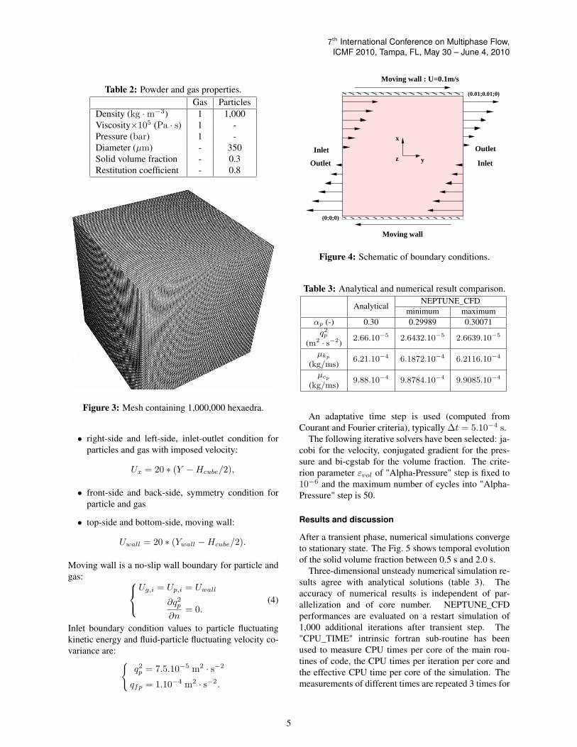
The computational domain is a cubic box of lengthHcube = 0.01 m (Fig. 2). The powder and gas materialproperties are given in table 2. The particulate phase ismonodispersed with diameter 350 µm.
The analytical solution with 0D approach gives thefollowing values:
• particle fluctuating kinetic energy:
q2p = 2.66.10−5 m2 · s−2,
• particle kinetic viscosity:
µkp= 6.21.10−4 kg ·m−1 · s−1,
• particle collisional viscosity:
µcp= 9.88.10−4 kg ·m−1 · s−1.
The gas phase is laminar and the particle agitationmodel is accomplished by solving a system of two trans-port equations: one for the particle turbulent agitationand one for the fluid-particle covariance. According to alarge particle to gas density ratio only the drag force istaken into account. It must be printed out that the gravity
0.01m
0.01m
0.01m
Figure 2: Sketch of the three-dimensional granular uni-form shear flow.
is also neglected in this case. Finally for this test case wesolve 10 equations (mass balance, momentum transport,particle turbulence).
Two different meshes have been employed to evalu-ate the performances: 1,000,000 cells from 1 up to 32nodes corresponding to 8 up to 256 cores and 10,503,459cells from 16 up to 128 nodes corresponding to 128 upto 1024 cores. The Fig. 3 shows the standard meshcomposed of 1,000,000 hexaedra with uniform cell size(∆x = ∆y = ∆z = 0.1 mm). The second mesh isalso a regular mesh of 10,503,459 hexaedra (219 cellsper direction).
Configuration is detailed in Fig. 4. Three kinds ofboundary conditions are used:
4
7th International Conference on Multiphase Flow,ICMF 2010, Tampa, FL, May 30 – June 4, 2010
Table 2: Powder and gas properties.Gas Particles
Density (kg ·m−3) 1 1,000Viscosity×105 (Pa · s) 1 -Pressure (bar) 1 -Diameter (µm) - 350Solid volume fraction - 0.3Restitution coefficient - 0.8
Figure 3: Mesh containing 1,000,000 hexaedra.
• right-side and left-side, inlet-outlet condition forparticles and gas with imposed velocity:
Ux = 20 ∗ (Y −Hcube/2),
• front-side and back-side, symmetry condition forparticle and gas
• top-side and bottom-side, moving wall:
Uwall = 20 ∗ (Ywall −Hcube/2).
Moving wall is a no-slip wall boundary for particle andgas:
Ug,i = Up,i = Uwall
∂q2p∂n
= 0.(4)
Inlet boundary condition values to particle fluctuatingkinetic energy and fluid-particle fluctuating velocity co-variance are: {
q2p = 7.5.10−5 m2 · s−2
qfp = 1.10−4 m2 · s−2.
Moving wall
Moving wall : U=0.1m/s
x
yz
(0;0;0)
(0.01;0.01;0)
InletOutlet
OutletInlet
Figure 4: Schematic of boundary conditions.
Table 3: Analytical and numerical result comparison.
AnalyticalNEPTUNE_CFD
minimum maximumαp (-) 0.30 0.29989 0.30071q2p 2.66.10−5 2.6432.10−5 2.6639.10−5
(m2 · s−2)µkp 6.21.10−4 6.1872.10−4 6.2116.10−4
(kg/ms)µcp 9.88.10−4 9.8784.10−4 9.9085.10−4
(kg/ms)
An adaptative time step is used (computed fromCourant and Fourier criteria), typically ∆t = 5.10−4 s.
The following iterative solvers have been selected: ja-cobi for the velocity, conjugated gradient for the pres-sure and bi-cgstab for the volume fraction. The crite-rion parameter εvol of "Alpha-Pressure" step is fixed to10−6 and the maximum number of cycles into "Alpha-Pressure" step is 50.
Results and discussion
After a transient phase, numerical simulations convergeto stationary state. The Fig. 5 shows temporal evolutionof the solid volume fraction between 0.5 s and 2.0 s.
Three-dimensional unsteady numerical simulation re-sults agree with analytical solutions (table 3). Theaccuracy of numerical results is independent of par-allelization and of core number. NEPTUNE_CFDperformances are evaluated on a restart simulation of1,000 additional iterations after transient step. The"CPU_TIME" intrinsic fortran sub-routine has beenused to measure CPU times per core of the main rou-tines of code, the CPU times per iteration per core andthe effective CPU time per core of the simulation. Themeasurements of different times are repeated 3 times for
5

7th International Conference on Multiphase Flow,ICMF 2010, Tampa, FL, May 30 – June 4, 2010
Figure 5: Temporal convergence of solid volume fraction between 0.5 s to 2.0 s.
each case to remove accidental and statistical error. Nosignificant difference of measured time is observed. Thefollowing analysis is based on the averaged values of the3 different runs.
In a first time, we focus on the strong scaling which isdefined as how the solution time varies with the numberof cores for a fixed total problem size. Secondly, we areinterested in the weak scaling that is to say how the solu-tion time varies with the number of processors for a fixedproblem size per processor (strong scaling is about sameproblem size in shorter time and weak scaling is aboutlarger problem size in same time). It is hard to achievea good strong-scaling at larger process counts since thecommunication overhead increases in proportion to thenumber of processes used.
Table 4: Effect of core number on effective core CPUtime for 1,000 iterations with the standard mesh.
number of Effective CPU time/core (s.)cores C1a C1b C2a C2b C3
8 35,621 35,325 12,150 12,462 15,46916 14,999 14,936 5,628 5,639 7,08732 5,959 5,877 2,598 2,567 3,25464 1,571 1,323 1,200 1,127 1,548
128 803 751 563 583 895256 580 757 449 485 1,269512 498 — 493 — —
6
7th International Conference on Multiphase Flow,ICMF 2010, Tampa, FL, May 30 – June 4, 2010
10 100
Number of cores
1e+03
1e+04
Eff
ectiv
e C
PU ti
me
(s.)
C1aC1bC2aC2bC3
Figure 6: NEPTUNE_CFD effective CPU time per core(standard mesh - 1,000 iterations).
0 32 64 96 128 160 192 224 256
Number of cores0
5
10
15
20
25
30
35
40
45
50
Spee
dup
C1aC1bC2aC2bC3Ideal
Figure 7: NEPTUNE_CFD speed-up with respect toTref of each cluster (standard mesh - 1,000 iterations).
The table 4 shows the effect of core number on effec-tive CPU time per core with the standard mesh. Compu-tation elapsed time is near to this time. The speedup isdefined as the ratio between the elapsed time to executea program on one node (ref = 1 node = 8 cores) and on aset of concurrent n nodes (n×8 cores) and the efficiencyis defined as the ratio between speedup and n:
Sp =TrefTn
=T8cores
Tn
Ef =Sp
n
(5)
where Tref is the effective core CPU time of the par-allel job on one node (8 cores) and Tn is the effectivecore CPU time of the parallel job on n nodes (n × 8cores).
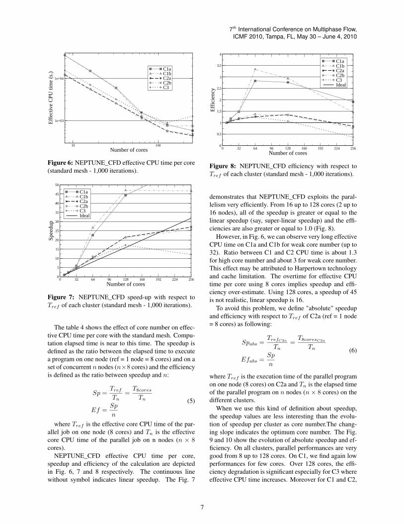
NEPTUNE_CFD effective CPU time per core,speedup and efficiency of the calculation are depictedin Fig. 6, 7 and 8 respectively. The continuous linewithout symbol indicates linear speedup. The Fig. 7
0 32 64 96 128 160 192 224 256
Number of cores0
0,5
1
1,5
2
2,5
3
3,5
4
Eff
icie
ncy
C1aC1bC2aC2bC3Ideal
Figure 8: NEPTUNE_CFD efficiency with respect toTref of each cluster (standard mesh - 1,000 iterations).
demonstrates that NEPTUNE_CFD exploits the paral-lelism very efficiently. From 16 up to 128 cores (2 up to16 nodes), all of the speedup is greater or equal to thelinear speedup (say, super-linear speedup) and the effi-ciencies are also greater or equal to 1.0 (Fig. 8).
However, in Fig. 6, we can observe very long effectiveCPU time on C1a and C1b for weak core number (up to32). Ratio between C1 and C2 CPU time is about 1.3for high core number and about 3 for weak core number.This effect may be attributed to Harpertown technologyand cache limitation. The overtime for effective CPUtime per core using 8 cores implies speedup and effi-ciency over-estimate. Using 128 cores, a speedup of 45is not realistic, linear speedup is 16.
To avoid this problem, we define "absolute" speedupand efficiency with respect to Tref of C2a (ref = 1 node= 8 cores) as following:
Spabs =TrefC2a
Tn=T8coresC2a
Tn
Efabs =Sp
n
(6)
where Tref is the execution time of the parallel programon one node (8 cores) on C2a and Tn is the elapsed timeof the parallel program on n nodes (n × 8 cores) on thedifferent clusters.
When we use this kind of definition about speedup,the speedup values are less interesting than the evolu-tion of speedup per cluster as core number.The chang-ing slope indicates the optimum core number. The Fig.9 and 10 show the evolution of absolute speedup and ef-ficiency. On all clusters, parallel performances are verygood from 8 up to 128 cores. On C1, we find again lowperformances for few cores. Over 128 cores, the effi-ciency degradation is significant especially for C3 whereeffective CPU time increases. Moreover for C1 and C2,
7

7th International Conference on Multiphase Flow,ICMF 2010, Tampa, FL, May 30 – June 4, 2010
0 32 64 96 128 160 192 224 256
Number of cores0
4
8
12
16
20
24
28
32A
bsol
ute
spee
dup
with
res
pect
to C
2a C1aC1bC2aC2bC3Ideal
Figure 9: NEPTUNE_CFD absolute speed-up with re-spect to Tref of C2a (standard mesh - 1,000 iterations).
0 32 64 96 128 160 192 224 256
Number of cores
0,2
0,4
0,6
0,8
1
1,2
1,4
1,6
Abs
olui
te e
ffic
ienc
y w
ith r
espe
ct to
C2a C1a
C1bC2aC2bC3Ideal
Figure 10: NEPTUNE_CFD absolute efficiency withrespect to Tref of C2a (standard mesh - 1,000 iterations).
we can note a MPI implementation effect. SGI MPTseems more efficient for several cores and Intel MPI isbetter for numerous cores.
The degradation for high core number is mainlycaused by the load unbalancing and the communica-tion overhead. Restitution time of a simulation is di-vided into computation time, communication and wait-ing time (send/receive/barrier MPI) and I/O time. Inthis case, I/O time is almost zero. The increase of corenumber corresponds to a decrease of cell number percore that is to say to a decrease of computation timeper core. Moreover, more cores implies more commu-nications between cores. When communication time in-creases quicker than calculation time decreases, the corelimit number is reached. Thus there is an optimal num-ber of cores for a mesh and a set of equations.
For this numerical simulation of a three-dimensionalgranular uniform shear flow solving 10 equations, NEP-TUNE_CFD performances are excellent on all clusters
Table 5: Effect of core number on core CPU time for500 iterations with the refined mesh on C2a.
number of cores CPU time/core (s.)8 109,22016 55,20532 28,87764 14,707
128 7,351256 3,721512 1,780768 1,220
1024 962
while cell number per core is greater than 10,000 that isto say while the core number is lower or equal to 128 fora mesh of 1,000,000 cells. On Nehalem cluster, perfor-mances are excellent up to 196 cores. It is noteworthythat the restitution time decreases up to 256 cores (5,000nodes per core).
NEPTUNE_CFD scalability is excellent on all plat-forms, with linear speedup on Harpertown and Shangaïtechnologies and super-linear speedup on Nehalem tech-nology.
To improve NEPTUNE_CFD performance evalua-tion, we perform numerical simulations with the refinedmesh (10,503,459 hexaedra) using from 1 up to 128nodes (8 up to 1024 cores). As CPU times are im-portant, these numerical simulations have been realizedonly on cluster C2a (the most recent cluster) with IntelMPI implementation. Performances are evaluated on arestart simulation of 500 additional iterations after tran-sient phase. Time measurements are still done with the"CPU_TIME" intrinsic fortran sub-routine and each runis repeated 3 times.
The table 5 shows effect of core number on effectiveCPU time per core with the refined mesh. The speedupand the efficiency are defined as previously.
NEPTUNE_CFD effective CPU time per core,speedup and efficiency of the calculation are depictedin Fig. 11, 12 and 13 respectively. The solid line rep-resents the linear speedup. The Fig. 12 demonstratesthat NEPTUNE_CFD exploits the parallelism very ef-ficiently even for large core number. The speedup issuper-linear up to 768 cores and linear for 1,024 coresand efficiency are also greater or equal to 1.0 (Fig. 13).Parallel performances are very good up to 128 nodes. Asin previous case, performance degradation begins whencommunications become preponderant to compute. Wecan assume that with this mesh speedup should be lowusing 2,048 cores .
This refined mesh study confirms that NEP-TUNE_CFD performances are excellent on Nehalem
8

7th International Conference on Multiphase Flow,ICMF 2010, Tampa, FL, May 30 – June 4, 2010
10 100 1000
Number of cores
1e+03
1e+04
1e+05
Eff
ectiv
e C
PU ti
me
(s.)
C2a
Figure 11: NEPTUNE_CFD effective CPU time percore (refined mesh - 500 iterations).
0 64 128 192 256 320 384 448 512 576 640 704 768 832 896 960 1024
Number of cores0
20
40
60
80
100
120
Spee
dup
C2aIdeal
Figure 12: NEPTUNE_CFD speed-up with ref = 1 node(refined mesh - 500 iterations).
cluster (C2) while cell number per core is higher than10,000 that is to say for a mesh of 10,503,459 cells acore number lower or equal to 1,024.
Hence, NEPTUNE_CFD strong scaling is excellentup to 1,024 cores in condition of respect of minimumcell number per core.
To understand these performances and time divide ac-cording to core number, NEPTUNE_CFD profiling isnecessary. We use MPINSIDE to evaluate MPI commu-nications and PerfSuite to get NEPTUNE_CFD timinginformations.
MPINSIDE increases slightly the elapsed time of nu-merical simulations but gives the right percentages ofelapsed time used by computation and by the differentMPI process. The main MPI function times and com-putational time are depicted in Fig. 14 and 15 for thestandard and the refined meshes for different core num-ber.
Using 8 cores, with the two meshes, computation time
0 64 128 192 256 320 384 448 512 576 640 704 768 832 896 960 1024
Number of cores
0,7
0,75
0,8
0,85
0,9
0,95
1
1,05
1,1
1,15
1,2
1,25
1,3
Eff
icie
ncy
C2aIdeal
Figure 13: NEPTUNE_CFD efficiency with ref = 1node (refined mesh - 500 iterations).
Figure 14: MPINSIDE profiling on C2a (standard mesh- 1,000 iterations).
is over 90 % of effective core CPU time. Barrier beforeMPI Allreduce time (b_allred) is weak and MPI Allre-duce time (allred) and Waitall time are almost nil. OtherMPI job times (overhead, send, receive, ...) are negligi-ble. Increasing core number, barrier before MPI Allre-duce time, MPI Allreduce time and Waitall time increaseand computational time decrease. Using 64 cores withthe standard mesh, computational time is only about70 % of core CPU time and using 512 cores computa-tional time is about 10 %. With the refined mesh, us-ing 256 cores, computational time is only about 70 % ofcore CPU time and using 1024 cores computational timeis about 25 %.
MPINSIDE gives informations about MPI functionsamples. Using 16 cores on refined mesh, during 500 it-erations, barrier before MPI Allreduce number is about55,904,240. Using 1,024 cores, barrier before MPIAllreduce number is about 3,574,704,128. Indeed, NEP-TUNE_CFD iterative solvers require a lot of MPI com-munications. Thus, a lot of messages are exchanged be-tween the cores many times in every iteration. For a high
9

7th International Conference on Multiphase Flow,ICMF 2010, Tampa, FL, May 30 – June 4, 2010
Figure 15: MPINSIDE profiling on C2a (refined mesh -500 iterations).
Figure 16: PerfSuite routine profiling on C2a (refinedmesh - 500 iterations).
core number, communication time is important. MPIN-SIDE confirms that MPI communications due to itera-tive solvers and "alpha pressure" step will be the mainlimitations to NEPTUNE_CFD massively parallel com-putation.
PerfSuite is used to know the most frequently askedroutines and functions (sample profiling). The Fig. 16shows the distribution of call for the main "routines" asa function of core number. The term "routines" herecorresponds to Intel MPI functions, function "parcom"(call of MPI function in fortran code), scheduling, rou-tine "prodsc" (fortran scalar product), routine "gradco".For low core number, percentage of NEPTUNE_CFDroutine sample for "gradco" and "prodsc" is about 90 %.For high core number (above 256), percentage of IntelMPI functions and scheduling is significant and becomepredominant for 1,024 cores.
PerfSuite enables to follow the called number to thecode, the “libc” library and the Intel MPI library (Fig.17). The increase of core number reduces strongly thepercentage the NEPTUNE_CFD call number.
This sample profiling can be compared with a timeprofiling included in NEPTUNE_CFD. This profiling
Figure 17: PerfSuite module profiling on C2a (refinedmesh - 500 iterations).
Table 6: NEPTUNE_CFD integrated profiling : detailsof one iteration with the refined mesh using 16 cores onC2a.
step CPU time (s.)post-processing 0.00
initialization 1.35velocity prediction 5.41"alpha-pressure" 109.70gradco routine 102.92jacobi routine 1.61
bi-cgstab routine 1.19Total time for iteration 120
gives per iteration per core, CPU time and main algo-rithm step time. MPI process time are included into rou-tines calling. In table 6, we can see that with the re-fined mesh and using 16 cores, one iteration requires acore CPU time of 120 s. meanly spent by the "alpha-pressure" step (109 s) and this one is meanly spent bythe conjugate gradient (103 s). For the same iteration butthis time using 1,024 cores, the core CPU time of 2.14 s.is meanly spent by the "alpha-pressure" step (1.88 s)which is meanly spent by conjugate gradient (1.76 s).
Between 80 % and 90 % of effective CPU time isspent in the step of matrix-inversion (iterative solvers).
A complementary aspect of performance evaluationis weak scaling. To respect a cell number per core of20,000 we have created seven regular meshes to evalu-ate performance from 16 cores up to 512. The table 7details the different meshes according to the core num-ber. NEPTUNE_CFD performances are evaluated ona restart simulation of 2,500 additional iterations aftertransient step on C2a.
In the Fig. 18, the weak scaling of NEPTUNE_CFDis shown. The effective CPU times per core are almostconstant. A weak scaling efficiency Efweak can be de-
10

7th International Conference on Multiphase Flow,ICMF 2010, Tampa, FL, May 30 – June 4, 2010
Table 7: NEPTUNE_CFD weak scaling : differentmeshes according to core number on C2a.
hexaedra number Core number Cell per core166,375 8 20,797328,509 16 20,532658,503 32 20,578
1,295,029 64 20,2352,515,456 128 19,6525,177,717 256 20,225
10,503,459 512 20,515
0 64 128 192 256 320 384 448 512Number of cores
5000
6000
7000
8000
9000
10000
11000
12000
Eff
ectiv
e C
PU ti
me
per
core
(s.
)
C2a
Figure 18: NEPTUNE_CFD effective CPU time percore for 2,500 iterations (20,000 cells per core)
fined as following:
Efweak =TrefTn
=T8cores
Tn(7)
(8)
where Tref is the elapsed time of the parallel job on onenode with smallest mesh and Tn is the elapsed time ofthe parallel job on n nodes with the respective meshes.The Fig. 19 shows that this weak scaling efficiency isvery good up to 512 cores (larger than 1).
This test case of granular shear flow exhibits accuracyof NEPTUNE_CFD results and excellent scalability ofthe code for large enough problem sizes.
Simulation of a industrial gas-solid fluidizedbed
The purpose of this test case is a three-dimensional in-stationnary dense fluidized bed at industrial scale. NEP-TUNE_CFD V1.07@Tlse is dedicated to this kind ofnumerical simulations Gobin et al. (2003).
The industrial reactor is composed of a cylinder and abulb at the top. The reactor is about 30 meter high and 5
0 64 128 192 256 320 384 448 512Number of cores
0,5
0,6
0,7
0,8
0,9
1
1,1
1,2
1,3
1,4
1,5
Wea
k sc
salin
g ef
fici
ency C2a
Figure 19: NEPTUNE_CFD weak scaling efficiencyfor 2,500 iterations (20,000 cells per core)
Table 8: Powder and gas properties of industrial reactor.Gas Particles
Density (kg/m3) 21.11 850Viscosity×105 (Pa.s) 1.54 -Pressure (bar) 20 -Vf (m.s−1) 0.67 -Mean diameter (µm) - 1,600Solid mass (kg) - 80,000Restitution coefficient - 0.9
meter wide as shown by Fig. 21. This bulb is an hemi-spherical dome with two smokes-tacks for gas outlet.
The powder properties and operating points are givenin table 8. In the industrial process, the particle phase ispolydispersed however the numerical simulations havebeen carried out with monodisperse particle having amedian diameter.
For the gas turbulence modeling, we use a standardk − ε model extended to the multiphase flows account-ing for additional source terms due to the interfacial in-teractions. For the dispersed phase, a coupled transportequations system is solved on particle fluctuating kineticenergy and fluid-particle fluctuating velocity covariance.According to large particle to gas density ratio only thedrag force is accounted as acting on the particles. Fi-nally, we solve 12 equations (mass balance, momentumtransport, gas and particle turbulence).
The three-dimensional mesh is shown by Fig. 20. Themesh, based on O-grid technique, contains 3,150,716hexaedra with approximately ∆x = ∆y = 30 mm and∆z = 90 mm.
At the bottom, the fluidization grid is an inlet for thegas with imposed superficial velocity corresponding tothe fluidization velocity Vf = 0.67 m.s−1. For the par-ticles this section is a wall. At the top of the fluidized
11

7th International Conference on Multiphase Flow,ICMF 2010, Tampa, FL, May 30 – June 4, 2010
Figure 20: Three-dimensional mesh containing 3,150,716 hexaedra.
bed reactor, we defined two free outlet for both the gasand the particles. The wall-type boundary condition isfriction for the gas and slip for the particles.
Up,n = 0
∂Up,τ∂n
= 0
∂q2p∂n
= 0,
(9)
An adaptative time step is used (computed fromCourant and Fourier criteria), typically ∆t = 1.10−3s.
The following iterative solvers have been selected: ja-cobi for the velocity, conjugated gradient for the pres-sure and bi-cgstab for the volume fraction. The crite-rion parameter εvol of "Alpha-Pressure" step is fixed tois 10−6 and the maximum number of cycles into "Alpha-Pressure" step is 50.
Results and discussion
The Fig. 22(a) shows the automatic domain decomposi-tion realized by METIS on the industrial reactor.
The Fig. 22(b) shows instantaneous solid volume frac-tion at 16.5 s.
NEPTUNE_CFD performances are evaluated on arestart simulation of 250 additional iterations after atransient phase corresponding to the destabilization ofthe fluidized bed (15 s.). Numerical simulations havebeen carried out only on cluster C2a (Nehalem architec-ture with Intel MPI).
As for the shear flow, the "CPU_TIME" intrinsic for-tran sub-routine has been used to measure the differenttimes per core.
The table 9 shows the effect of core number on effec-tive CPU time per core.
As described above, we calculate speedup and effi-ciency. NEPTUNE_CFD effective CPU time per core,speedup and efficiency of this calculation are depicted
12

7th International Conference on Multiphase Flow,ICMF 2010, Tampa, FL, May 30 – June 4, 2010
Figure 21: Sketch of the industrial polymerization reac-tor.
Table 9: Effect of core number on core CPU time onC2a (industrial fluidized bed).
number of cores CPU time/core (s.)8 68,47916 40,88532 19,23364 8,625
128 4,129256 1,707384 1,275512 1,173768 1,190
1024 1,220
in Fig. 23, 24 and 25 respectively. The continuous linewithout symbol indicates linear speedup and ideal effi-ciency. The Fig. 24 demonstrates that NEPTUNE_CFDexploits the parallelism very efficiently. From 16 up to384 cores (48 nodes), the speedup is super-linear and ef-ficiencies are also greater than 1.0 (Fig. 25).
Parallel performances are very good up to 384 cores,the restitution time decreases up to 512 cores. Overthis value, an increase of core number is not interest-ing but restitution time does not increase significantly.The increase of communication time is balanced by thedecrease of computational time.
On the same way, in this case realistic industrial densefluidized bed solving 12 equations, NEPTUNE_CFDHPC is excellent on Nehalem cluster (C2) while cell
(a) (b)
Figure 22: Industrial fluidized bed. (a) Automaticdomain decomposition using Metis. (b) Instantaneoussolid volume fraction field.
number per core is higher than 10,000 that is to say fora mesh of 3,150,716 hexaedra a core number inferior orequal to 384. If we consider the "cost" of the numericalsimulation about CPU time, the optimum performancesare obtained with 256 cores.
This test case illustrates excellent NEPTUNE_CFDscalability performances on a industrial geometry.Strong scaling is good for large enough problem sizes(up to 384 cores with this mesh).
Conclusion
Three-dimensional numerical simulations of two differ-ent cases of dense gas-particle flows have been per-formed to evaluate NEPTUNE_CFD parallel perfor-mances. The first one exhibits accuracy of numericalresults and demonstrates high NEPTUNE_CFD parallelcomputing performances up to 1,024 cores. The secondone, a realistic fluidized bed shows NEPTUNE_CFDefficiency and scalability on industrial geometry. Theresults show linear speed-up using Harpertown andShangaï technologies and super-linear speedup with Ne-halem technology. For the two test cases, a minimumof 10,000 cells of mesh per core is needed and 20,000is recommended. A next step of evaluation of NEP-TUNE_CFD performances will focus on effect of phasenumber (fluids) and of solved equation number on theminimum cell number per core. On the other, we will
13

7th International Conference on Multiphase Flow,ICMF 2010, Tampa, FL, May 30 – June 4, 2010
10 100 1000
Number of cores
1e+03
1e+04
1e+05
Eff
ectiv
e C
PU ti
me
(s.)
C2a
Figure 23: NEPTUNE_CFD effective CPU time percore on C2a (250 iterations) on an industrial reactor.
0 64 128 192 256 320 384 448 512 576 640 704 768 832 896 960 1024
Number of cores0
20
40
60
80
100
120
Spee
dup
C2aIdeal
Figure 24: NEPTUNE_CFD speed-up with ref =1 nodeon C2a (250 iterations) on an industrial reactor.
evaluate the performances using several thousands ofcores such as realized on the Open Source CFD code:Code_SATURNE by Sunderland et al. (2008).
Moreover, the profilings have shown that the most im-portant part of CPU time is spent in the step of matrix-inversion by the iterative approach. The next implemen-tation of multi-grid in NEPTUNE_CFD should improvestrongly the global performances of the code.
Acknowledgments
This work was granted access to the HPC resources ofCALMIP under the allocation P0111 (Calcul en Midi-Pyrénées). This work was also granted access to theHPC resources of CINES under the allocation 2010-026012 made by GENCI (Grand Equipement Nationalde Calcul Intensif).
0 64 128 192 256 320 384 448 512 576 640 704 768 832 896 960 1024
Number of cores
0,4
0,5
0,6
0,7
0,8
0,9
1
1,1
1,2
1,3
Eff
icie
ncy
C2aIdeal
Figure 25: NEPTUNE_CFD efficiency with ref = 1node on C2a (250 iterations) on an industrial reactor
References
G. Balzer, A. Boelle, and O. Simonin. Eulerian gas-solidflow modelling of dense fluidized bed. FLUIDIZATIONVIII, Proc. International Symposium of the EngineeringFoundation, J.F. Large and C. Laguerie (Editors), pages409–418, 1995.
A. Gobin, H. Neau, O. Simonin, J.R. Llinas, V. Reiling,and J.L Sélo. Fluid dynamic numerical simulation of agas phase polymerization reactor. Int. J. for Num. Meth-ods in Fluids, 43, pages 1199–1220, 2003.
G. Karypis and V. Kumar. A fast and highly quality mul-tilevel scheme for partitioning irregular graphs. SIAMJournal on Scientific Computing, Vol. 20, No 1, pages359–392, 1999.
N. Méchitoua, M. Boucker, S. Mimouni, S. Pigny, andG. Serre. Numerical simulation of multiphase flow withon elliptic oriented fractional step method. Third Inter-national Symposium on Finite Volumes for Complex Ap-plications, Porquerolle France, 2002.
N. Méchitoua, M. Boucker, J. Laviéville, J.M. Hérard,S. Pigny, and G. Serre. An unstructured finite vol-ume solver for two-phase water/vapour flows mod-elling based on elliptic oriented fractional step method.NURETH 10, Séoul, Corée du Sud, 2003.
T. Randrianarivelo, H. Neau, O. Simonin, and F. Nico-las. 3d unsteady polydispersed simulation of uraniumhexafluoride production in a fluidized bed pilot. In Proc.6th Int. Conf. on Multiphase Flow, Leipzig (Germany),paper S6_Thu_A_46,, 2007.
O. Simonin. Prediction of the dispersed phase tur-bulence in particle-laden jets. Gas-Solid Flows-1991,ASME FED, Vol. 121, pages 197–206, 1991.
14

7th International Conference on Multiphase Flow,ICMF 2010, Tampa, FL, May 30 – June 4, 2010
O. Simonin. Statistical and continuum modelling of tur-bulent reactive particulate flows. Theoretical and Ex-perimental Modeling of Particulate Flows. Lecture Se-ries 2000-06, Von Karman Institute for Fluid Dynamics,Rhode Saint Genèse, Belgium, 2000.
A.G. Sunderland, M. Ashworth, N. Li, C. Moulinec,Y. Fournier, and J. Uribe. Towards petascale comput-ing with parallel cfd codes. Parallel CFD 2008, LyonFrance, 2008.
15