Embed Size (px)
Citation preview

70 The Open Plasma Physics Journal, 2009, 2, 70-78
1876-5343/09 2009 Bentham Open
Open Access
Nonthermal Plasma Mitigation of Shock Wave in Supersonic Airflow
Spencer Kuo*
Department of Electrical and Computer Engineering, Polytechnic Institute of New York University, Brooklyn, NY, USA
Abstract: A non-thermal technique using a plasma spike, generated by 60 Hz periodic electric discharge, for shock wave
mitigation is presented. The experiments were conducted in a Mach 2.5 wind tunnel. A plasma spike was generated in
front of a wind tunnel model; it led to a transformation of the shock from a well-defined attached shock into a highly
curved shock structure, which had increased shock angle and also appeared in diffused form. As seen in a sequence with
increasing discharge intensity, the shock in front of the model moved upstream to become detached with increasing
standoff distance from the model and was eliminated near the peak of the discharge. The power measurements excluded
the heating effect as a possible cause of the observed shock wave modification. A theory using a cone model as the shock
wave generator is presented to explain the observed plasma effect on shock wave. The analysis has shown that the plasma
generated in front of the model can effectively deflect the incoming flow; such a flow deflection modifies the structure of
the shock wave generated by the cone model, as shown by the numerical results, from a conic shape to a curved one. The
shock front moves upstream with a larger shock angle, matching well with that observed in the experiment.
INTRODUCTION
The airflow disturbances deflected forward from a spacecraft, flying faster than the sound speed (~ 1200 km/h), cannot get away from the spacecraft; these disturbances coalesce into a shock wave in front of it. Shock wave appears in the form of a steep pressure gradient. It introduces a discontinuity in the flow properties at the shock front location, where is the reachable edge of the reflected flow disturbances from the spacecraft. Shock wave causes the pressure in front of the spacecraft to increase considerably, resulting to significant enhancement of the flow drag and friction on the spacecraft. Moreover, shock wave produces notorious sonic boom on the ground. It occurs when flight conditions (such as the altitude, speed, etc) are changing to cause shock wave unsteady. The faster the aircraft flies, the larger the boom. The noise issue raises environmental concerns, which have precluded for example, the Concorde supersonic jetliner from flying overland. Thus shock waves have been a detriment for the development of high-speed aircrafts.
A physical spike [1] is currently used in a supersonic spacecraft to move original bow shock upstream from the blunt-body nose location to its tip location in the new form of a conical oblique shock. It improves the body aspect ratio of a blunt-body and significantly reduces the wave drag. However, the additional frictional drag occurring on the spike structure and related cooling requirements limit the performance of a physical spike. Also another drawback of physical spikes is its sensitivity to off-design operation of the vehicle, i.e., flight Mach number and vehicle angle of attack. If the aspect ratio l/D of the spike length l to the aircraft frontal diameter D is less than one, it also limits the practical use of the physical spike alone for shock wave modification.
*Address correspondence to this author at the Department of Electrical and
Computer Engineering, Polytechnic Institute of New York University,
Brooklyn, NY, USA; E-mail: [email protected]
Therefore, the development of new technologies for the attenuation or ideal elimination of shock wave formation around a supersonic vehicle has attracted considerable attention. The anticipated results of reduced fuel consumption and having smaller propulsion system requirements, for the same cruise speed, will lead to the obvious commercial gains that include larger payloads at smaller take-off gross weights and broadband shock noise suppression during supersonic flight.
Plasma introduced non-thermal modification effects on the structure of shock waves have been evidenced in a number of wind tunnel experiments. As shown by [2], high-pressure metal vapor (high Z) plasma, produced inside the chamber of a cone-cylinder model by exploding wire off electrical short circuit and injected into the supersonic flow through a nozzle, could significantly reduce the wave drag. The measured drag reduction was too large to be attributed to the thermal effect. The subsequent wind tunnel experiments by other investigators [3-8] showed that the shock front increased dispersion in its structure and/or standoff distance from the model when plasma was generated ahead of a model
either by off-board/on-board
electric discharges. In the experiments conducted by Bivolaru and Kuo [7, 8], a wind tunnel model of truncated 60
0 cone, with a slender central-spike protruding out of the
cut circular cross section to the tip location of a perfect cone, was used. In a Mach 2.5 supersonic flow, a bow shock was generated in front of this truncated cone. The spike did not cause noticeable modification on the shock wave structure. As plasma was introduced through a dc discharge at the spike region of the model, it was found that the discharge could produce apparently cone-shaped plasma around the spike of the model, and that the original bow shock in front of the nose of the model was converted to a conical shock, similar to that generated by a perfect cone [9]. The measured temperature elevation was too small to account for the detected drag reduction. Baryshnikov et al. [3] and Bivolaru and Kuo [7, 8] investigated the relaxation time of the shock

Nonthermal Plasma Mitigation of Shock Wave in Supersonic Airflow The Open Plasma Physics Journal, 2009, Volume 2 71
structure modification in decaying discharge plasma. A long-lasting plasma effect on the shock structure (i.e., after the discharge ceases, it takes much longer than the discharge period to recover to the baseline state) was observed in both experiments.
In this work, a 600 cone model was used for shock
generation. To install on-board electric discharge electrodes, this model was constructed by combining a truncated 60
0
cone with a cone-shaped ceramic tube which insulated a central electrode. The ceramic insulator together with a short protruding part of the central electrode which was machined in cone-shape was used to fill in the truncated part of the cone. Thus, this model is defect from a perfect cone. Experiments using on-board 60 Hz periodic electric discharge to produce torch plasma for shock mitigation [10] are performed. The experimental results evidencing non-thermal plasma effect on shock wave are reported; theory and numerical results are presented to interpret the experimental observations. The experimental setup is described in Sec. 2. The experimental results are presented in Sec. 3. Theory and the results of the numerical analysis to interpret the experimental observations are presented in Sec. 4. Summary is given in Sec. 5.
EXPERIMENTAL SETUP
Experiments were conducted in the test section, with a 0.38 m 0.38 m cross section, of a supersonic blow-down wind tunnel. The upstream airflow had a flow speed v = 570 m/s, temperature T1 = 135 K, and a pressure P1 = 0.175 atm.
Wind Tunnel Model
The wind tunnel model has a 600 truncated-cone body
connected to a cylindrical body attached to a holder. The nose of the model, shown in the schematic of the model presented in Fig. (1a), is a cone-shaped ceramic insulator with a short protruding spike, which replaces the truncated part of the cone. In other words, this model consists of a 60
0
truncated-cone body, a sharpened (600 cone shape) solid
tungsten rod of a diameter d = 2.4 mm and a cone-shaped ceramic insulator which holds the tungsten rod in place concentrically with the truncated-cone body. The tungsten rod and the body form the electrodes for electric discharge, which is periodic at 60 Hz. The truncated 60
0 cone has a
frontal diameter D = 11.1 mm and a height L = 12.7 mm. The cylindrical base of the cone has a diameter Db = 25.4
mm. The gap between the tungsten rod and the inner wall at the front of the truncated-cone body is 3.5 mm. The distance from the tip to the edge of the truncated-cone surface is about 5-mm.
Periodic Discharge
The 60 Hz power supply for periodic discharge operation is shown in Fig. (1b). During one of the two half cycles when the diode is forward biased, the capacitor is charged so the voltage across the electrodes is low and there is no discharge. During the other half cycle, the diode has a reverse bias. The charged capacitor increases the voltage across the electrodes and breakdown occurs. The discharge normally initiates in the region near the tip electrode where the applied electric field concentrates due to the cylindrical geometry. Therefore, it prefers the tip electrode to be negative so that the electrons can be pushed to the upstream region. Indeed, plasma effect on the shock wave structure has been observed only when the tip of the model is designated as the cathode.
The voltage across the electrodes had an asymmetric wave- form with a peak of about 4.5 kV, exceeding the 4 kV (for 5-mm gap) required for avalanche breakdown. The electric field intensity near the tip exceeded 1 MV/m before breakdown occurred and reduced to be less than 100 kV/m as the discharge current reached the peak. The peak and average power of the discharge were about 1.2 kW and 100 W, respectively. The peak electron density of the discharge measured outside the wind tunnel exceeded 10
19
electrons/m3. During the run, the background pressure
dropped. It reduced the gas breakdown threshold field; the ionization rate and thus the electron density should increase.
Optical Diagnostics
Shadowgraph method was used to optically diagnose the flowfield around the spike and nose of the cone. When a uniform collimated light beam passes through a flow, the second derivative of the density flow field in a direction perpendicular to the light beam causes the deflection of the light rays, which results in light intensity variation manifested by a shadow image. A dark curve in the shadowgraph clearly reveals the location of a stationary shock front, where the second derivative of the density distribution is very large and the transmitted light reduces to a minimum.
Fig. (1). Schematics of (a) the wind tunnel model and (b) the circuits for the 60 Hz periodic electric discharge.
� ��
��
������� �����
�� ���
���
����� ���
����
�������
����
����!�����"����
72 The Open Plasma Physics Journal, 2009, Volume 2 Spencer Kuo
In the diagnostic system, an incandescent lamp (LS) with beam-forming optics and filters was used as a light source. A parabolic mirror, having a diameter of 0.3 m and focal length of 3.7 m, collimated the divergent beam from the light source through the wind tunnel test section windows. On the other side of the wind tunnel, a black and white charge coupled device (CCD) camera, with the frame rate of 30 frames per second and exposure time of 1/60 sec (which is slightly less than four times of each discharge period), was used to record the shadowgraph image of the flow dynamics either directly or from that projected on a screen. A video camera as the corresponding one to the CCD camera was used to record the spatial distribution and temporal evolution of the plasma glow with the same frame rate and exposure time. The video graph recorded in each frame was an integrated result over the exposure time and thus the temporal variation of the shock wave structure and plasma glow during a single discharge period could not be recorded directly.
Continuous video graph of the flow can reveal important information regarding the dynamic behavior of the flow field. Although the starting times in recording each event (i.e., the starting time of each frame) by the two cameras are not synchronized, the events recorded by the two cameras can still be synchronized by counting number of frames from the reference frames, except, there will be a maximum possible time difference that is half of the exposure time (i.e., 1/120 sec). Therefore, the results extracted from videotapes recording the shadowgraph images of the flow and plume images of plasma can provide the correlation between the plasma distribution and the modification of the shock structure, which will be very useful information regarding the experiment because the plasma effect on shock wave is not expected to be always observed in the experiment. Any consistent relationships appearing in the correlation can help to deduce required plasma conditions to achieve significant plasma effect on the shock wave, as being elaborated in Sec. 3.
It is noted that in the presence of time varying plasma perturbation, the shock front is not stationary. It will move from the normal location to the maximal perturbed-location and move back to the normal location during one perturbation period. If the exposure time of the shadowgraph is less than the perturbation period, only the shock front at the outmost location will appear as the shadow. The contrast of the shadow image is expected to be much less than that for a stationary shock front. Since the shock front is responding to the integrated effect of the plasma perturbation, the strongest perturbation on the shock structure will appear near the end of each discharge, rather than at the peak of the discharge. After the discharge is over, shock front starts to move from its maximum displaced location back to its normal location.
The electric discharge in different cycles can be quite different, which is out of control experimentally. In some cycles intense plasma was produced, and weak plasma or even no plasma was produced in other cycles. Therefore, throughout a run we can record a sequence of shadowgraphs showing different shock structures. Each shadowgraph corresponds to a video graph of the plasma airglow. In a
cycle of strong discharge, plasma density still has to grow from near zero to the maximum and then decay to near zero. The time varying perturbation is expected to cause the shock front position to also vary in time. However, the shadowgraph only records the outmost position of the shock front responding to the integration of total perturbation. Different level of discharge has a different level of the plasma perturbation on shock wave and produces a different shadowgraph. Therefore, a sequence of differently perturbed shock front positions can be used to simulate the shock front position at the different time in a cycle of a large discharge. This is a time assembly approach to reconstruct the time variation of the shock front in one cycle showing a strong plasma effect on shock wave, to be demonstrated in Figs. (3, 4).
EXPERIMENTAL RESULTS
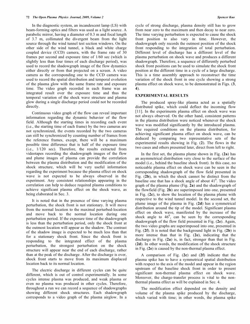
The produced spray-like plasma acted as a spatially distributed spike, which could deflect the incoming flow [11]. In the experiments plasma effect on shock wave was not always observed. On the other hand, consistent patterns in the plasma distribution were noticed whenever the shock wave was modified significantly by the introduced plasma. The required conditions on the plasma distribution, for achieving significant plasma effect on shock wave, can be deduced by comparing two representative sets of the experimental results showing in Fig. (2). The flows in the two cases and others presented later, direct from left to right.
In the first set, the plasma plume shown in Fig. (2a) has an asymmetrical distribution very close to the surface of the model (i.e., behind the baseline shock front). In this case, no noticeable plasma effect on shock wave can be seen in the corresponding shadowgraph of the flow field presented in Fig. (2b), in which the shock cannot be distinct from the baseline one that has a shock angle of about 41
0. The video
graph of the plasma plume (Fig. 2a) and the shadowgraph of the flowfield (Fig. 2b) are superimposed into one, presented in Fig. (2c), to show the location of the plasma plume with respective to the wind tunnel model. In the second set, the plume image of the plasma in Fig. (2d) has a symmetrical distribution around the tip of the model. Significant plasma effect on shock wave, manifested by the increase of the shock angle to 46
0, can be seen by the corresponding
shadowgraph of the flow field presented in Fig. (2e). Again, the two video graphs are superimposed into one, presented in Fig. (2f). It is noted that the background light in Fig. (2b) is more intense than that in Fig. (2e), indicating that the discharge in Fig. (2a) is, in fact, stronger than that in Fig. (2d). In other words, the modification of the shock structure in Fig. (2e) is caused by the non-thermal plasma effect.
A comparison of Fig. (2c) and (2f) indicate that the plasma spike has to have a symmetrical spatial distribution with respect to the axis of the model and appear in the region upstream of the baseline shock front in order to present significant non-thermal plasma effect on shock wave. Moreover, the charge-transfer process is vital to the non-thermal plasma effect as will be explained in Sec. 4.
The modification effect depended on the density and volume of the plasma spike produced by the discharge, which varied with time; in other words, the plasma spike

Nonthermal Plasma Mitigation of Shock Wave in Supersonic Airflow The Open Plasma Physics Journal, 2009, Volume 2 73
Fig. (2). (a) An asymmetrically distributed plasma plume, (b) the
shadowgraph of the flow field showing negligible plasma effect on
shock wave, and (c) plasma plume in (a) superimposed to the
shadowgraph in (b); (d) plasma plume symmetrically distributed
around the tip of the model, (e) the shadowgraph of the flow field
showing strong plasma effect on shock wave, and (f) plasma plume
in (d) superimposed to the shadowgraph in (e).
increased its size and intensity from near zero to the maximum and then to decay to near zero. This time varying spike could cause the shock front position to also vary in time. Though the temporal variation of the shock wave structure during a single discharge period could not be recorded directly, the desired information regarding the transient behavior of the flow field was extracted from the continuous shadowgraphy of the flow. This is demonstrated in Fig. (3), which includes a sequence of four shadowgraphs showing the responses of the shock wave to the growth and decay of the plasma spike in a discharge cycle.
The growth of the plasma spike is manifested by the variation of the background brightness in the shadowgraphs. First shadowgraph shown in Fig. (3a) is in the case that the discharge is off. Therefore, the shadowgraph is dark (absence of background light from the plasma) and is the baseline one. The next two, presented in Figs. (3b) and (3c), correspond to the situation that the discharge is intensifying before reaching the peak. The baseline shock front is first split into two as shown in Fig. (3b), with a new one located
upstream and having a larger shock angle; the two then merge into one, as shown in Fig. (3c), at the new upstream location as the plasma spike is further intensified. The two shadowgraphs in (a) and (c) are superimposed into one in the insert of Fig. (3a) to show the increase of the shock angle by the plasma spike. As the plasma spike is intensified to reach the peak, its modification effect on the shock structure also reaches the maximum. The shock front in Fig. (3d) is diffused; it spreads from the one shown in Fig. (3c) to further upstream region. A comparison of Figs. (3d) and (3a) clearly observes a transformation of the shock from a well-defined attached shock into a diffused and highly curved shock structure having a larger shock angle. This modification is an indication of shock wave being weakened by this plasma spike, evidencing the effectiveness of this plasma scheme in reducing wave drag at supersonic speeds.
The baseline shock can become detached when the flow deflection by the plasma spike is further increased. This is demonstrated in Fig. (4) by a sequence of shadowgraphs (a) to (d) of the flowfield corresponding to the four discharge situations in the same run, no discharge, strong discharge, stronger discharge, and very strong discharge. In the experiment, a Pitot tube was installed in the tunnel, which can be seen with its usual detached shock front on the top portion of the shadowgraphs. Comparison of Fig. (4a) and (4b) clearly indicates an upstream displacement of the shock front along with a larger shock angle indicating a transformation of the shock from a well defined attached shock into a classic highly curved bow shock structure. A highly diffused detached shock front, showing a further upstream propagation of the bow shock with an even more dispersed shape and a larger shock angle, is observed in Fig. (4c). A shock-free state is observed in Fig. (4d) as the discharge is further intensified. It is noted that the shock still appears in front of Pitot probe, indicating that the flow is supersonic. Using plasma to eliminate shock is an ultimately desirable result that has significant consequences in minimizing wave drag and shock noise at supersonic speeds.
The shadowgraphs of the flowfield presented in Fig. (4a-4c) are superimposed into one presented in Fig. (4e). The insert in Fig. (4e) exemplifies that plasma generated by the discharge has a distribution spreading around the cone model. Clearly, plasma causes the shock front to move upstream with increasing standoff distance from the model and to become more and more diffused in the process. The detached shock fronts appear more diffused than the attached one (which is also modified by the plasma) presented in Fig. (3d).
Based on the measured peak and average discharge power, the upper bound of the peak and average temperature enhancements are estimated to be Tpeak 26 K (for Pin|peak = 1.2 kW) and Tave 2.2 K (for Pin|average = 100 W). The peak temperature perturbation is less than 10% of the unperturbed, 285 K, in the region behind the shock, and less than 20 % of the upstream gas temperature of 135 K; and the average temperature perturbation is less than 1% and 2 %, respectively. Thus the heating could at most increase the sound speed and decrease the Mach number by 5 %. These changes were too small to introduce any significant thermal effects.

74 The Open Plasma Physics Journal, 2009, Volume 2 Spencer Kuo
Fig. (4). Shadowgraphs of shock in different states during the
discharge, (a) baseline, (b) detached, (c) dispersed, and (d) shock-
free; (e) a superimposed shadowgraph (from the three
shadowgraphs in (a) to (c)) showing the relative position of the
shock fronts modified by plasma with increasing discharge
intensity; the insert shows the plume image of the plasma produced
by the electrical discharge.
THEORY AND NUMERICAL RESULTS
Shock wave is characterized by its structure and shock angle , which depend on its generator and the Mach number M and deflection angle of the flow [12]. The charged particles in plasma, accelerated by the applied electric field, can deflect a neutral flow through collisions to modify shock wave. It requires that plasma be generated in the region upstream of the baseline shock front in order to deflect the upstream flow. The deflection is particularly effective when plasma is produced directly within the neutral flow and has a symmetrical spatial distribution with respect to the axis of the model. Ions moving through their own gas are subject to charge transfer between the ion and the neutral gas. The
charge transfer cross-section between N2+ and N2 in the
relevant low ion energy regime is larger than 3 10-19
m2
[13]. An ion that has traveled a single charge-transfer free path becomes a neutral particle but retains its velocity, which is usually low. Most of the converted neutrals move at subsonic speed, these particles do not contribute to the shock wave formation. Some of them may move at supersonic speed, however, they don’t drift together and thus the produced disturbances off the model are expected to spread out in the form of expansion waves, rather than coalesce into shocks. The ions converted from neutrals through charge-transfer are collected by the cathode and do not contribute to the shock wave generation either. Electrons deflect the neutral flow through elastic collisions. Symmetrical deflection makes it easy to satisfy momentum conservation. The shock of the deflected flow is expected to have a larger shock angle (than that of the baseline one) and a modified structure, representing a weaker shock.
Plasma Spike and Flow Deflection
Symmetrically distributed plasma in front of the base-line shock, acting as a spike to deflect the flow [14-16], will be incorporated into the formulation of the theory for interpreting the experimental observations. This plasma spike is introduced at a location in front of the model by an on-board electrical discharge, which is triggered by a negative voltage applied between the grounded body of the cone and the tip of the cone located at z = 0, which is insulated from the body. The sharpness of the tip helps to enhance the electric field intensity in the region in front of the tip.
Using the planar projection of the model as a two-dimensional model, the equipotential lines between the two electrodes, with the central electrode biased negatively, are evaluated numerically by using a Poisson solver. The result is presented in Fig. (5), in which the distribution of the electric field that is perpendicular to the equipotential line is also indicated. As shown, the applied electric field can extend to a relatively large region upstream of model, but the electric field intensity decreases with distance from the tip as modeled to be E -(A0/R
2)( z z + r r ), where A0 is
proportional to the applied voltage and R = (z2 + r
2)
1/2 is the
distance of the field point away from the tip. This local field sustains the discharge in the upstream region and accelerates
Fig. (3). An assembled time sequence of four shadowgraphs (a)-(d) to represent the flow response to the plasma spike during one discharge
period in the middle of a wind tunnel run at Mach 2.5. The insert in (a) is a superimposed shadowgraph from the two shadowgraphs in (a)
and (c).

Nonthermal Plasma Mitigation of Shock Wave in Supersonic Airflow The Open Plasma Physics Journal, 2009, Volume 2 75
the produced electrons, which deflect the incoming flow via momentum transfer collisions. The deflection is most effective when plasma has a symmetric distribution around the tip. In this situation, the transverse momentum perturbation of the neutral flow is distributed symmetrically in opposite directions, which causes the maximum deflection of the flow and yet requires the minimum change of its total momentum in the transverse direction. Flow lines illustrating the flow deflection is also presented in Fig. (5). Electrons cause
more perturbation on the velocity distribution of the
flow than ions. This is because the flow collides with electrons much more frequently than with ions. Moreover, the local field, in the region upstream of the tip of the model, accelerates ions in the direction of the flow, rather than opposite to the flow.
Fig. (5). Distributions of the equipotential line and electric field
between two electrodes of a two-dimensional model and the
deflection of the incoming airflow by the discharge-produced
plasma.
Flow deflection is evaluated based on the model presented in Fig. (5), in which a uniform airflow from left to right with a velocity V10 = V10 z encounters a plasma spike at z = -z0. Electrons produced by the discharge interact with the airflow through elastic electron-neutral collisions. On the other hand, the ion-neutral interaction is more complicated. It involves both elastic and charge transfer inelastic collisions.
The electron density distribution of the spike is first determined through the spatial distribution of the ionization frequency i ~
5.3a, where = E/Ecr, Ecr is the breakdown
threshold field, and a is the attachment rate. Let ne0 = ne( =0, = -1) = n0exp[( i0 - a)t0] is the steady state electron density at (r = 0, z = -z0) and model ne( , = -1) = ne0exp[( i - i0) t0] = ne0exp{-s[1 (1 +
2)
2.65] }, where = r/z0 and
= z/z0; t0 is the transient period for the plasma density to build up at (r = 0, z = -z0), i0 = i( =0, = -1), and t0 is an equivalent time converting from the radial decay rate of the electron density distribution; s = i0 t0 = 0.85 will be assumed to model the radial profile of the electron density distribution. The two electric field components in the interaction region at z = -z0 (i.e., = -1) are represented
approximately by Ez = E0/(1 + 2) and Er = -E0 /(1 +
2),
where E0 = A0/z0.
The momentum equations for the three fluids: electrons, positive ions and neutral molecules, in this weakly ionized plasma in the presence of the imposed electric field are:
med(neve)/dt = neme en(ve – V1) + neme ei(vi - ve)
eneE (1)
mid(nivi)/dt = nimi in(vi – V1) nimi c(vi – V10)
neme ei(vi - ve) + eniE (2)
mnd(nnV1)/dt = neme en(ve – V1) + nimi in(vi – V1)
+ nimi c(vi – V10) (3)
where V10 and V1 are the upstream neutral flow velocity before and after interacting with the plasma; c (> in) is the ion-neutral charge transfer collision frequency, which is dominated by charge transferring between the same type particles. Because the ion speed is subsonic, after the charge transfer the converted neutral particles from ions do not contribute to the shock wave formation. On the other hand, the converted ions from neutral particles form a supersonic flow; however, this ion flow is collected by the cathode and does not contribute to the shock wave formation either. In the quasi steady state, (1) and (2) lead to neme en(ve – V1) + nimi in(vi – V1) + nimi c(vi – V10) = e(ni – ne)E; thus, (3) can be reduced approximately to
mnd(nnV1)/dt e(ni – ne)E (4)
where ni = ni0exp(- ct) and ni0 ne.
It is noted that in (3) the pressure gradient term is neglected by assuming that the density and temperature of the airflow do not change considerably during the transit period of the airflow passing through the plasma spike. We now integrate (4) over a transit period tn = z0/V10, the time for the airflow to pass through the plasma spike of length z0. We obtain
V1(1)
(r, tn) [V10/(1 + cni0tn/nn)] z
V10 exp{-s[1 (1 + 2)
2.65] }
[ n(1 + 2)
-1( z - )]
V10z V10 exp{-s[1 (1 + 2)
2.65] }
[ n(1 + 2)
-1(z - r ) + nz ] (5)
where n = (eE0tn/V10mn)(ne0/nn) and n = (ne0/nn) ( ctn). Thus the deflected flow has spatially dependent deflection angle and Mach number M1, which are obtained from (5) to be (r) = tan
-1 [V1r(r)/V1z(r)] and M1(r) = {[V1r(r)
2 +
V1z(r)2]1/2
/V10}M10, where M10 is the Mach number of the unperturbed flow.
Supersonic Flow Over a Cone
We now apply Taylor-Maccoll’s theory [12] to analyze the deflected supersonic flow (5) over a cone. We start with a simple situation that the incoming flow from the left propagates at a constant angle with respect to the axis of the cone. In the steady state, a conic shock front signified by a step pressure jump is formed to separate the flow into regions 1 and 2 of distinct entropies as sketched in Fig. (6).

76 The Open Plasma Physics Journal, 2009, Volume 2 Spencer Kuo
In the figure, the cone is placed horizontally (along the z-axis); thus, the flow velocity V1 in region 1 has an angle with respect to the z (cone’s) axis; the flow has a Mach number M1. The geometry of Fig. (6) is adapted from Fig. (10.4) in the book by Anderson [12], which is for the special case with = 0.
The conic shock has an angle to be
determined. In region 2 immediately behind the shock front, the flow has a deflection angle with Mach number M2 and velocity V2 = VR2 a R V 2 a , where a R and a are unit vectors in spherical coordinate system, the origin is at the tip of the cone, and the z axis is along the cone axis.
Fig. (6). Geometry for the numerical solution of deflected flow over
a cone.
The shock angle and deflection angle are related by the M relation of a wedge, which is derived through the continuity conditions at the flow discontinuity and in the case of = 0 can be found in textbooks, as, for example, Eq. 4.17 in the book by Anderson [12]. This relation can easily be generalized for 0. Because the changes across a conic shock wave (similar to across an oblique shock) are governed by the normal component of the free-stream velocity, the relevant parameters in the equations are Mn1 = M1sin( ) and Mn2 = M2sin( ). Letting = ( ) and = ( ), these two relations become Mn1 = M1sin and Mn2 = M2sin( ), which are expressions similar to those in the = 0 case. Therefore, the M relation (similar to that for M [12, 14]) is derived to be
tan = 2 cot {(M12sin
2 1)
/[M12( + cos2 ) + 2]} (6)
where is usually chosen to be 1.4.
The normalized Taylor-Maccoll equation for conical flows (Eq. 10.15 of Anderson [12]) is expressed as
0.2 [1 G2 G
2][2G + G cot + G ] G
2[G + G ]
= 0 (7)
where G = VR2/V2max, G = dG/d , G = d2G/d
2, and = 1.4
is assumed.
The boundary conditions of (7) are given by
G( ) = f(M2) cos( )
and
G ( ) = f(M2) sin( ) (8)
where f(M2) = V2/V2max = [(5/M22) + 1]
1/2, M2 = Mn2/sin(
), Mn2 = {[(M1sin )2 + 5]/[7(M1sin )
2 1]}
1/2, and is
determined by (6).
Eq. (7) will be solved based on the numerical procedure outlined in section 10.4 of Chapter 10 in the Anderson book [12]. That is, a proper = c is found by iteration in solving (7) such that the normal component of the flow velocity on the cone surface V 2( c) = VR2 ( c) = G ( c)V2max becomes zero, where c is the half cone angle of the model. The effect of a localized plasma spike on the shock wave is then inferred from changes in the deflection angle and in the Mach number M1 of the flow, where and M1 vary with r, the radial coordinate with respect to the z-axis. Since = ( + ), the flow deflection, i.e., 0, increases the shock angle as seen experimentally.
Numerical Results
The deflection angle (r) and the Mach number M1(r) of the deflected flow vary with the intensity of the discharge (gauged by the peak electron density n0), where M10 = 2.5 was used in the numerical calculations. For tn = 0.88 10
5
sec (i.e., z0 = 5 mm), nn ~ 1025
m-3
(i.e., P1 = 0.175 atm and T1 = 135 K), V10 = 570 m/s, c 2 in 2 10
9 sec
-1, and
assuming E0 ~ 106 V/m, we then have n = 0.309 10
-20 ne0
and n = 0.235 10-20
ne0. Let ne0 = 3.24 1020
m 3, so that
n = and n = 0.76 . The two functions (r) and M1(r) are plotted in Fig. (7a) and (7b) for the parameter = 0.23, 0.2, and 0.1.
Using these results for each (i.e., n0) as the parameters at the shock front location, the corresponding oblique angle
c(r) = c + of the shock front can be determined by solving (7) iteratively to meet the condition that the normal component of the flow velocity on the cone surface G ( c) = 0. Thus the position of the shock front can be determined by the trajectory equation
dz/dr = cot c = cot( c + ) (9)
The result in the case of = 0.2 (corresponding to a relatively intense discharge) is presented in Fig. (7c), in which the baseline shock front, having a shock angle 0 = 42.6
0 (for c = 30
0), is also presented for comparison. As
shown, the shock angle is increased to 460 by the plasma
spike; agreeing well with the experimental result which is inserted in the same figure for comparison. In this case, the peak electron density of the plasma spike used in the numerical calculation is n0 = 6.5 10
19 m 3, which
agrees
with that produced by the on-board diffused arc discharge in the experiments presented in Sec. 3.
DISCUSSION
The wave drag of the shock on the cone depends on the strength of the shock, which in turn depends on the Mach number of the flow. It is shown that the Mach number M1( ) of the deflected flow in the tip region is smaller than M10. A decrease of the effective Mach number of the incoming flow in the tip region verifies that the plasma spike can indeed reduce the wave drag of the shock on the cone. Moreover, the modified shock structure moves upstream away from the cone, it also results to the reduction of the wave drag on the cone.
�
�
�
��
��
�
��
� � � �� ������� �� ����
�
� �� �
�
�

Nonthermal Plasma Mitigation of Shock Wave in Supersonic Airflow The Open Plasma Physics Journal, 2009, Volume 2 77
It is noted that the solution of the Taylor-Maccoll equation represents an attached shock. When c in Fig. (2) exceeds a maximum value, i.e., c > cmax, there exists no Taylor-Maccoll solution, and the shock becomes detached [12]. cmax decreases with the decrease of M1 and the equivalent c of the cone increases with the increase of . As shown in Fig. (7), M1 decreases and increases as increases (i.e., plasma density increases). = 0.23 is the largest value for which a Taylor-Maccoll solution can be obtained. In other words, the numerical analysis indicates that the shock becomes detached when > 0.23 (i.e., n0 > 7.5
1019
m 3). Its standoff distance from the model is expected to increase with a further increase of n0, consistent with the experimental results presented in Fig. (4).
SUMMARY
Wind tunnel experiments were conducted to explore the non-thermal plasma effects on the shock wave structures. An imperfect cone-shaped model was used as the shock generator and facilitated with electrodes for on-board 60 Hz periodic discharge to generate plasma in front of the model. The tip of the central electrode in the model was shaped to match the cone angle. The sharp tip also made easy on the discharge by enhancing the electric field intensity in the region in front of the tip. Moreover, the central electrode of the model was arranged as the cathode. This arrangement together with the favorable electric field distribution made electron current in the discharge much easier to pass through the shock front into the upstream (lower pressure) region before returning to the body of the model as the anode. As shown in Fig. (2d), the discharge could produce plasma in the upstream region and with a symmetric distribution around the central electrode, which was found to be the
necessary conditions to achieve noticeable plasma effects on shock waves.
The introduced plasma caused the shock front to have increased dispersion in its structure as well as standoff distance from the model. A theory based on the deflection of the incoming flow by a symmetrically distributed plasma spike in front of the shock as the process to modifying the shock wave structure has been formulated and analyzed numerically. As demonstrated in Fig. (7c), the numerical results are in good agreement with the experimental ones. This theory facilitates the understanding of the experimental observations, which cannot be reasonably explained by a simple heating effect.
NOMENCLATURE
c, = Cone half angle, upstream flow angle with respect to the z (cone’s) axis
M, , = Mach number, flow deflection angle, shock angle
V, P, T = Neutral flow velocity/pressure/temperature
ve,I = Electron/ion fluid velocity
r, z, = Radial and axial coordinates in the cylindrical coordinate system, r/z0
R, z0 = The distance [= (z2 + r
2)
1/2] of a point away
from the tip, effective length of the plasma spike
E, Ecr = Applied electric field, breakdown threshold field
a, i, c = Attachment rate, ionization rate, ion-neutral charge transfer collision frequency
Fig. (7). (a) ( ), the deflection angle, and (b) M1( ), the Mach number, of an incoming flow after being scattered by a plasma spike; (c)
attached shocks in a supersonic flow over a 600 cone (represented by the shadow region) for two cases, = 0 (no discharge) and = 0.2
(corresponding to an intense discharge), where = r/z0 and = z/z0. The line labeled = 0 represents the baseline shock front. The insert is a
superimposed shadowgraph showing a baseline shock front and a shock front modified by the plasma spike, for comparison with the
numerical results.
���
���
������
�
�
�
�
�
�
�� � � �
�
�
���
�
� ����
�
�
��
���
���
�����
���
����
��
��� ���
���
���
���
���
���
������ ��� ��� ������ ���
����� �
�
#$��%�&���������$�'�� ������&�'�
( ����� $��%�&����
)��������

78 The Open Plasma Physics Journal, 2009, Volume 2 Spencer Kuo
en, in = Electron-neutral collision frequency, ion- neutral collision frequency
ne,i, nn = Electron/ion density, neutral density
REFERENCES
[1] Chang PK. Separation of flow. Oxford: Pergamon Press 1970.
[2] Gordeev VP, Krasilnikov AV, Lagutin VI, Otmennikov VN. Plasma technology for reduction of flying vehicle drag. Fluid Dyn
1996; 31: 313-17. [3] Baryshnikov AS, Basargin IV, Dubinina EV, Fedotov DA.
Rearrangement of the shock wave structure in a decaying discharge plasma. Tech Phys Lett 1997; 23: 259-60.
[4] Kuo SP, Kalkhoran IM, Bivolaru D, Orlick L. Observation of shock wave elimination by a plasma in a Mach 2.5 flow. Phys
Plasmas 2000; 7: 1345-8. [5] Kuo SP, Bivolaru D. Plasma effect on shock waves in a supersonic
flow. Phys Plasmas 2001; 8: 3258-64. [6] Appartaim R, Mezonlin ED, Johnson JA III. Turbulence in plasma-
induced hypersonic drag reduction. AIAA J 2002; 40: 1979-83.
[7] Bivolaru D, Kuo SP. Observation of supersonic shock wave
mitigation by a plasma aero-spike. Phys Plasmas 2002; 9: 721-23. [8] Bivolaru D, Kuo SP. Aerodynamic modification of supersonic flow
around truncated cone using pulsed electrical discharges. AIAA J 2005; 43: 1482-9.
[9] Kuo SP, Bivolaru D. The similarity of shock waves generated by a cone-shaped plasma and by a solid cone in a supersonic airflow.
Phys Plasmas 2007; 14: 023503(1-5). [10] Kuo SP, Koretzky E, Orlick L. Methods and apparatus for
generating a plasma torch. US Patent No: US 6329628 B1 2001. [11] Kuo SP. Plasma mitigation of shock wave: experiments and theory.
Shock Waves 2007; 17: 225-39. [12] Anderson JD Jr. Modern compressible flow. New York: McGraw-
Hill 1990. [13] Brown SC. Basic data of plasma physics. Cambridge: The M.I.T.
Press 1967. [14] Kuo SP, Kuo SS. A physical mechanism of non-thermal plasma
effect on shock wave. Phys Plasmas 2005; 12: 012315(1-5). [15] Kuo SP, Kuo SS. Theoretical study of plasma effect on a conical
shock wave. Phys Plasmas 2006; 13: 033505(1-6). [16] Kuo SP. Shock wave modification by a plasma spike: experiment
and theory. Phys Scr 2005; 71: 535-9.
Received: April 1, 2009 Revised: May 2, 2009 Accepted: May 11, 2009
© Spencer Kuo; Licensee Bentham Open.
This is an open access article licensed under the terms of the Creative Commons Attribution Non-Commercial License (http://creativecommons.org/licenses/by-nc/3.0/) which permits unrestricted, non-commercial use, distribution and reproduction in any medium, provided the work is properly cited.