Embed Size (px)
Citation preview
optimascale.com
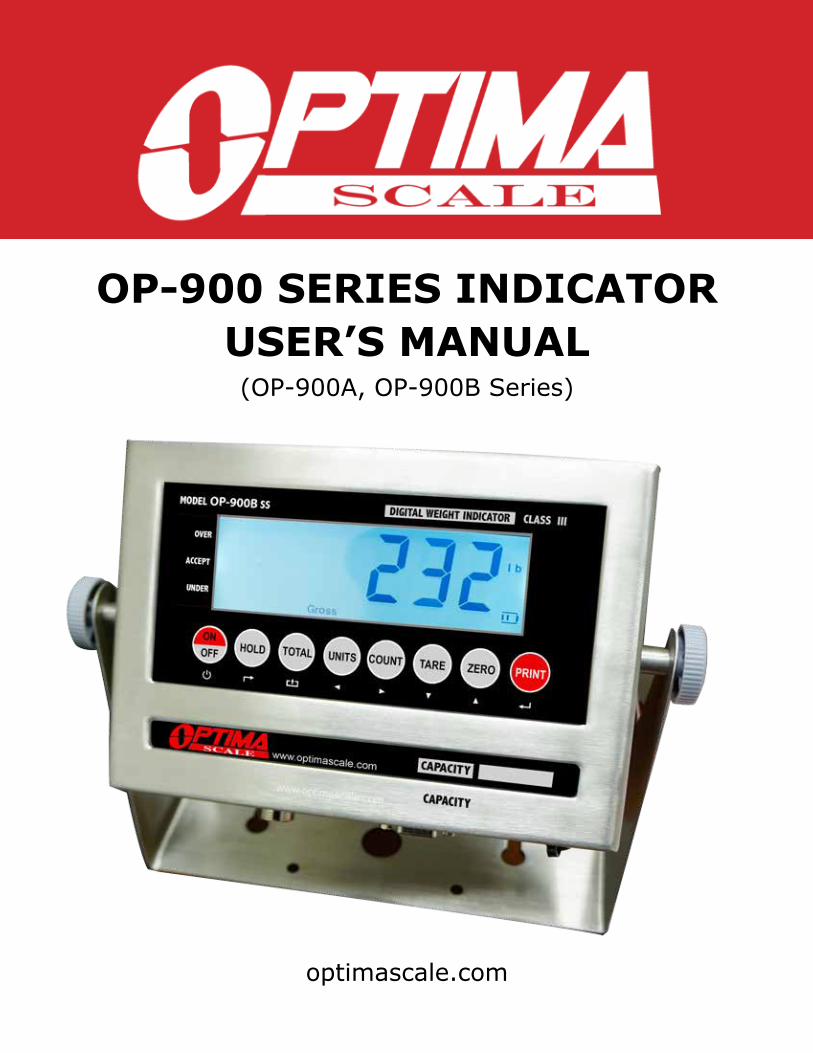
OP-900 SERIES INDICATORUSER’S MANUAL(OP-900A, OP-900B Series)
TABLE OF CONTENTS
Safety Precautions 1
Preparations and Set Up 1
Features 2
Specifications 3
Power Supply 4
Displays 5
Display and Key Descriptions 6
Operating Instructions 7
Calibration 9
Indicator Parameter Settings 11
Connectors 16
RS232 Serial Output Format 18
4-20 mA Analog Output 22
Relay Output 23
Troubleshooting 24
Q&A 25
Contact Us 26
SAFETY PRECAUTIONS For safe operation of the weighing indicator, please follow these instructions: ● Calibration inspection and maintenance of the indicator are prohibited by non-pro-
fessional staff ● Please ensure that the indicator rests on a stable surface ● The indicator is a piece of static sensitive equipment; Please cut off power during
electrical connections ● Touching the internal components by hand is prohibited ● DO NOT exceed the rated load limit of the unit ● DO NOT step on the unit ● DO NOT jump on the scale ● DO NOT use this product if any of the components are cracked ● DO NOT use for purposes other then weight taking ● To avoid damaging the battery do not keep charger plugged in once battery is fully
charged ● Make sure the weight is not over the Max capacity as it could damage the load cell
inside ● Material that has a static electric charge could influence the weighing. Discharge
the static electricity of the samples, if possible. Another solution to the problem is to wipe both sides of the pan and the top of the case with an anti-static agent
Please take anti-static prevention measuresAny accumulated charge on the body of the human operator should be discharged first before opening the protective container with ESDS devices inside. The discharge can be accomplished by: ● Putting a hand on a grounded surface or, ideally, by wearing a grounded Anti-static
Wrist Strap and an Anti-static Mat
PREPARATION & SET UP ● Plug into a wall outlet to avoid interference with other wirings ● Turn on the balance while there is no load ● We suggest to warm-up the balance by powering on 5 minutes before use for
accurate weighing ● Calibration may be required before weighing when the balance is initially installed
or moved from a location
FEATURES ● Multiple weighing units: (kg/g/lb/oz/lb:oz) ● Gross/Tare/Zero ● Count weighing ● Accumulation weighing ● Overload / Underload indication ● Print ● Splash proof keyboard and display ● Can connect to a secondary large display/scoreboard ● Relay output (optional) ● 4-20mA analog output (optional) ● Can connect to a PC or printer for data logging (optional) ● Wireless capability (optional)
Indicator Model OptionsThe OP-900 series consists of the OP-900A (LED) series and OP-900B (LCD) series. Options for rechargeable battery, stainless steel enclosure, computer connection, relay output and analog output can be added.Please contact [email protected] for a list of possible options.
Technical Parameters
● Accuracy class: 5000 e ● Resolution - Display: 30,000 ; ADC: 2,000,000 ● Zero stability error: TK0 < 0.1μV//K ● Span stability error: TKspn < ± 6 ppm//K ● Sensitivity (internal): 0.3 μV / d ● Input voltage: -30 to +30mV DC ● Excitation circuit: 5 VDC, 4 wire connection, 6 load cell of 350ohm max ● AC power: AC 100-250V (use only the included 9V adapter supplied) ● Operation temperature: -10 °C ~ +40 °C ● Operation humidity: ≤90%RH ● Storage temperature: -40 °C ~ +70 °C (32-104°F)

SPECIFICATIONSFIGURE 1: INDICATOR MEASUREMENTS
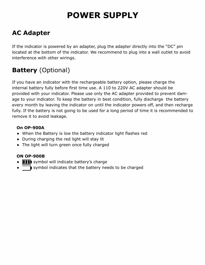
POWER SUPPLY
AC Adapter
If the indicator is powered by an adapter, plug the adapter directly into the “DC” pin located at the bottom of the indicator. We recommend to plug into a wall outlet to avoid interference with other wirings.
Battery (Optional)
If you have an indicator with the rechargeable battery option, please charge the internal battery fully before first time use. A 110 to 220V AC adapter should be provided with your indicator. Please use only the AC adapter provided to prevent dam-age to your indicator. To keep the battery in best condition, fully discharge the battery every month by leaving the indicator on until the indicator powers off, and then recharge fully. If the battery is not going to be used for a long period of time it is recommended to remove it to avoid leakage.
On OP-900A ● When the Battery is low the battery indicator light flashes red ● During charging the red light will stay lit ● The light will turn green once fully charged
ON OP-900B ● symbol will indicate battery’s charge ● symbol indicates that the battery needs to be charged
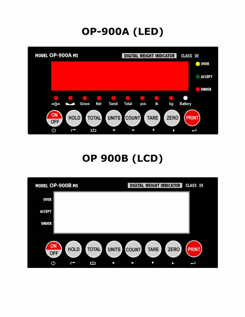
OP-900A (LED)
OP 900B (LCD)
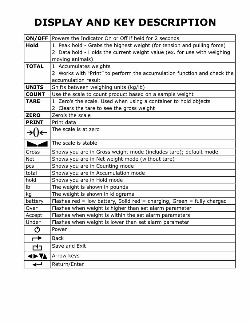
DISPLAY AND KEY DESCRIPTION ON/OFF Powers the Indicator On or Off if held for 2 secondsHold 1. Peak hold - Grabs the highest weight (for tension and pulling force)
2. Data hold - Holds the current weight value (ex. for use with weighing moving animals)
TOTAL 1. Accumulates weights2. Works with “Print” to perform the accumulation function and check the accumulation result
UNITS Shifts between weighing units (kg/lb)COUNT Use the scale to count product based on a sample weight TARE 1. Zero’s the scale. Used when using a container to hold objects
2. Clears the tare to see the gross weightZERO Zero’s the scalePRINT Print data
The scale is at zero
The scale is stable
Gross Shows you are in Gross weight mode (includes tare); default modeNet Shows you are in Net weight mode (without tare)pcs Shows you are in Counting modetotal Shows you are in Accumulation modehold Shows you are in Hold modelb The weight is shown in pounds kg The weight is shown in kilogramsbattery Flashes red = low battery, Solid red = charging, Green = fully chargedOver Flashes when weight is higher than set alarm parameter Accept Flashes when weight is within the set alarm parametersUnder Flashes when weight is lower than set alarm parameter
Power
BackSave and Exit
Arrow keys
Return/Enter

OPERATING INSTRUCTIONSPower On
● Turn on the power by pressing the power button for 2 seconds. Once on, the scale will flash the voltage and then begin to auto-check and count down from 0-9 sequentially before entering the weighing mode Note: Anything on the scale before powering on will automatically be tared out.
Zeroing ● When indicator is turned on the screen should read 0 ● If the screen reads any number other than 0 before weighing, press the ZERO key
to set to 0
Unit Selection ● To switch between measuring units (kg, lb, oz) press the UNITS key
Tare Function ● When the indicator is in gross mode (gross light is shown) pressing the TARE key
will Tare the current weight on the scale and enter the net mode (net light shown) ● For example if you are using a container add the container to the scale, press tare
and the display will show the tare symbol and reset back to 0 ● Add your sample to the scale to weigh without the weight of the container ● To exit Tare mode press the TARE key again to enter gross mode
Note: If you remove the container the scale will show the minus weight of the containerTo use a pre-set tare weight ● Press and hold the tare key for 2 seconds ● Input the tare weight using the arrow keys ● Press print key to confirm
Counting Function ● In weighing mode: Put a sample weight on the scale ● Then press the COUNT key to go to the counting mode (“pcs” will light up) ● It will then display the sample number (ex. PCS 0) which you can change using the
up or down arrows (Sample options are 5, 10, 20, 50, 100, 200, 500) ● Press the PRINT key to confirm your sample number ● The scale is now ready to start counting, load your product on the scale and the
indicator will show the quantity ● To exit counting mode press the COUNT key ● If you want to count a different product hold the PRINT and COUNT key together
and the sample pieces will reset back to zero

Accumulation ● In weighing mode load the first weight, once stable press the ACCUM key to enter
the accumulation mode. The “total” light will display. ● Remove weight and press ZERO key before adding the second weight to the scale ● Once stable press ACCUM key to add the weight to the accumulated total ● Press ZERO Key before adding the next weight to the scale ● Repeat previous step until all desired weights have been added to the total (max 999
times) ● When you are done and want to display the accumulated total, press the ACCUM
and PRINT key together. The accumulated number “n###” (the number of weights you are adding together) will flash on the display followed by the total. The total will display by flashing between 2 sets of numbers
● There are 8 digits in total, the display will flash 4 at a time, the first 4 on the left and the last 4 on the right. For example if the first 4 digits are “0012” and the last 4 digits are “3456” the actual weight is 001234.56 or 1234.56 lbs/kg
● If you want to print the accumulated total, hold the PRINT key while the last 4 digits of the total are shown
● To exit accumulation mode, wait for the last 4 digits to the right of the screen to appear, and then press and hold the ACCUM key. “CLr n” will be displayed, asking you if you want to keep the data?
● If NO you do not want to clear the accumulated total, then keep “CLr n”. ● If YES you do want to clear the accumulated total, then use the arrow key to change
to “CLr y”. ● Finally, press the PRINT key to select exit accumulation mode
Print ● If the indicator is connected to a printer and the weight on the scale is stable press the
PRINT key to print the current weight ● In accumulation mode press the PRINT key when the last 4 digits of the total weight
are shown to print the total weightNote: In tare mode the printer can not print if negative weight is shown
HoldThere are 2 different hold functionsPeak Hold: Grabs the highest weight (for materials testing, such as tension and pulling force)Data Hold: Grabs the current weight and holds it so it will not change/fluctuate (ex. for use with weighing moving animals)
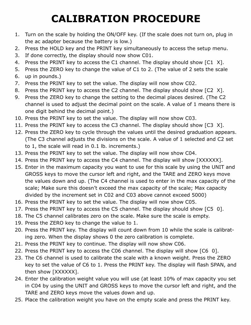
CALIBRATION PROCEDURE1. Turn on the scale by holding the ON/OFF key. (If the scale does not turn on, plug in
the ac adapter because the battery is low.)2. Press the HOLD key and the PRINT key simultaneously to access the setup menu.3. If done correctly, the display should now show C01.4. Press the PRINT key to access the C1 channel. The display should show [C1 X].5. Press the ZERO key to change the value of C1 to 2. (The value of 2 sets the scale6. up in pounds.)7. Press the PRINT key to set the value. The display will now show C02. 8. Press the PRINT key to access the C2 channel. The display should show [C2 X].9. Press the ZERO key to change the setting to the decimal places desired. (The C2
channel is used to adjust the decimal point on the scale. A value of 1 means there is one digit behind the decimal point.)
10. Press the PRINT key to set the value. The display will now show C03.11. Press the PRINT key to access the C3 channel. The display should show [C3 X].12. Press the ZERO key to cycle through the values until the desired graduation appears.
(The C3 channel adjusts the divisions on the scale. A value of 1 selected and C2 set to 1, the scale will read in 0.1 lb. increments.)
13. Press the PRINT key to set the value. The display will now show C04.14. Press the PRINT key to access the C4 channel. The display will show [XXXXXX].15. Enter in the maximum capacity you want to use for this scale by using the UNIT and
GROSS keys to move the cursor left and right, and the TARE and ZERO keys move the values down and up. (The C4 channel is used to enter in the max capacity of the scale; Make sure this doesn’t exceed the max capacity of the scale; Max capacity divided by the increment set in C02 and C03 above cannot exceed 5000)
16. Press the PRINT key to set the value. The display will now show C05.17. Press the PRINT key to access the C5 channel. The display should show [C5 0].18. The C5 channel calibrates zero on the scale. Make sure the scale is empty.19. Press the ZERO key to change the value to 1.20. Press the PRINT key. The display will count down from 10 while the scale is calibrat-
ing zero. When the display shows 0 the zero calibration is complete.21. Press the PRINT key to continue. The display will now show C06.22. Press the PRINT key to access the C06 channel. The display will show [C6 0].23. The C6 channel is used to calibrate the scale with a known weight. Press the ZERO
key to set the value of C6 to 1. Press the PRINT key. The display will flash SPAN, and then show [XXXXXX].
24. Enter the calibration weight value you will use (at least 10% of max capacity you set in C04 by using the UNIT and GROSS keys to move the cursor left and right, and the TARE and ZERO keys move the values down and up.
25. Place the calibration weight you have on the empty scale and press the PRINT key.

26. The scale will count down from 10 to 0. Once 0 has been reached, the display will show CALEnd.
27. Press the PRINT key to continue. The display will now show C07.28. Press the ACCUM/TOTAL key to save and exit the setup menu.29. The scale has now been calibrated. The display will show the value of the calibration
weight on the scale.30. If the scale does not show the value of the calibration weight, check that the feet on
the platform are not screwed in too tightly, and verify that the platform is level.31. Unload the scale; the display should read 000000.32. If the scale does not display 00000, check that the feet on the platform are not
screwed in too tightly, and verify that the platform is level.
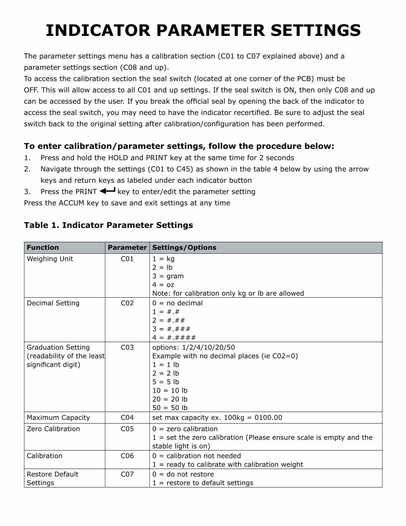
INDICATOR PARAMETER SETTINGSThe parameter settings menu has a calibration section (C01 to C07 explained above) and a parameter settings section (C08 and up). To access the calibration section the seal switch (located at one corner of the PCB) must beOFF. This will allow access to all C01 and up settings. If the seal switch is ON, then only C08 and upcan be accessed by the user. If you break the official seal by opening the back of the indicator to access the seal switch, you may need to have the indicator recertified. Be sure to adjust the seal switch back to the original setting after calibration/configuration has been performed.
To enter calibration/parameter settings, follow the procedure below:1. Press and hold the HOLD and PRINT key at the same time for 2 seconds2. Navigate through the settings (C01 to C45) as shown in the table 4 below by using the arrow
keys and return keys as labeled under each indicator button3. Press the PRINT key to enter/edit the parameter settingPress the ACCUM key to save and exit settings at any time
Table 1. Indicator Parameter Settings
Function Parameter Settings/Options
Weighing Unit C01 1 = kg2 = lb3 = gram4 = ozNote: for calibration only kg or lb are allowed
Decimal Setting C02 0 = no decimal1 = #.#2 = #.##3 = #.###4 = #.####
Graduation Setting(readability of the least significant digit)
C03 options: 1/2/4/10/20/50 Example with no decimal places (ie C02=0)1 = 1 lb2 = 2 lb5 = 5 lb10 = 10 lb20 = 20 lb50 = 50 lb
Maximum Capacity C04 set max capacity ex. 100kg = 0100.00
Zero Calibration C05 0 = zero calibration1 = set the zero calibration (Please ensure scale is empty and the stable light is on)
Calibration C06 0 = calibration not needed1 = ready to calibrate with calibration weight
Restore DefaultSettings
C07 0 = do not restore1 = restore to default settings
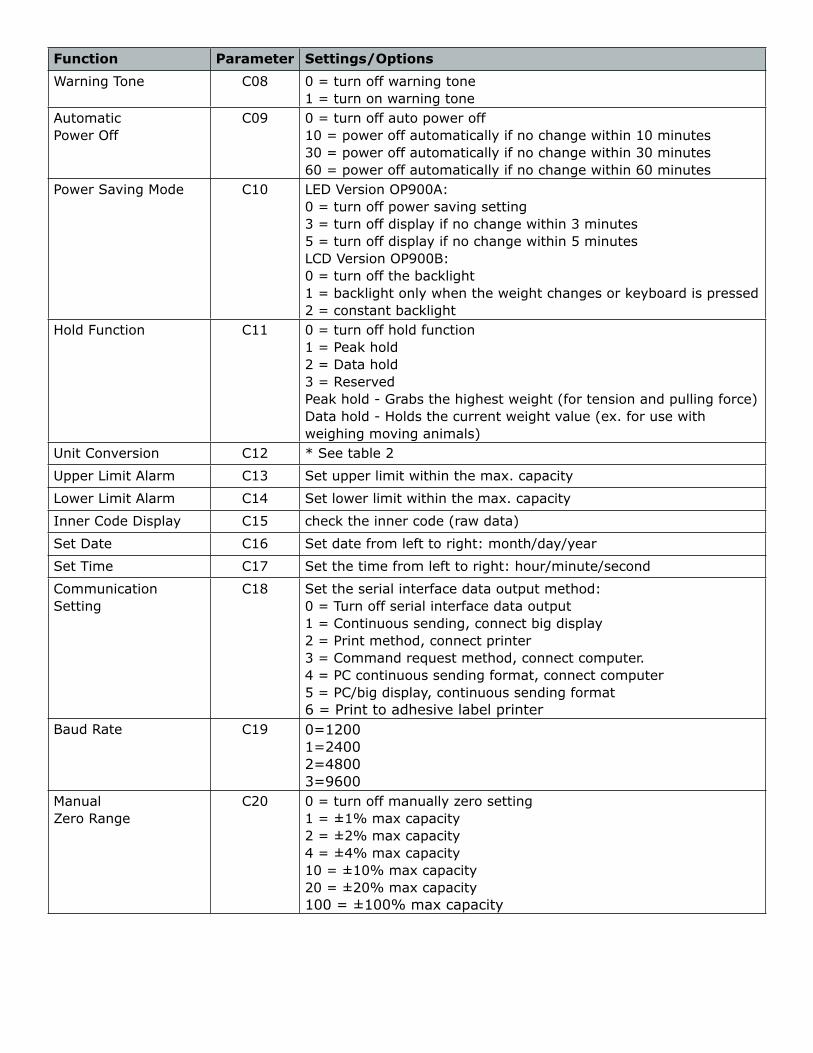
Function Parameter Settings/Options
Warning Tone C08 0 = turn off warning tone1 = turn on warning tone
Automatic Power Off
C09 0 = turn off auto power off10 = power off automatically if no change within 10 minutes30 = power off automatically if no change within 30 minutes60 = power off automatically if no change within 60 minutes
Power Saving Mode C10 LED Version OP900A:0 = turn off power saving setting3 = turn off display if no change within 3 minutes5 = turn off display if no change within 5 minutesLCD Version OP900B:0 = turn off the backlight 1 = backlight only when the weight changes or keyboard is pressed2 = constant backlight
Hold Function C11 0 = turn off hold function1 = Peak hold2 = Data hold3 = ReservedPeak hold - Grabs the highest weight (for tension and pulling force)Data hold - Holds the current weight value (ex. for use with weighing moving animals)
Unit Conversion C12 * See table 2
Upper Limit Alarm C13 Set upper limit within the max. capacity
Lower Limit Alarm C14 Set lower limit within the max. capacity
Inner Code Display C15 check the inner code (raw data)
Set Date C16 Set date from left to right: month/day/year
Set Time C17 Set the time from left to right: hour/minute/second
Communication Setting
C18 Set the serial interface data output method:0 = Turn off serial interface data output1 = Continuous sending, connect big display2 = Print method, connect printer3 = Command request method, connect computer.4 = PC continuous sending format, connect computer5 = PC/big display, continuous sending format6 = Print to adhesive label printer
Baud Rate C19 0=12001=24002=48003=9600
ManualZero Range
C20 0 = turn off manually zero setting1 = ±1% max capacity2 = ±2% max capacity4 = ±4% max capacity10 = ±10% max capacity20 = ±20% max capacity100 = ±100% max capacity
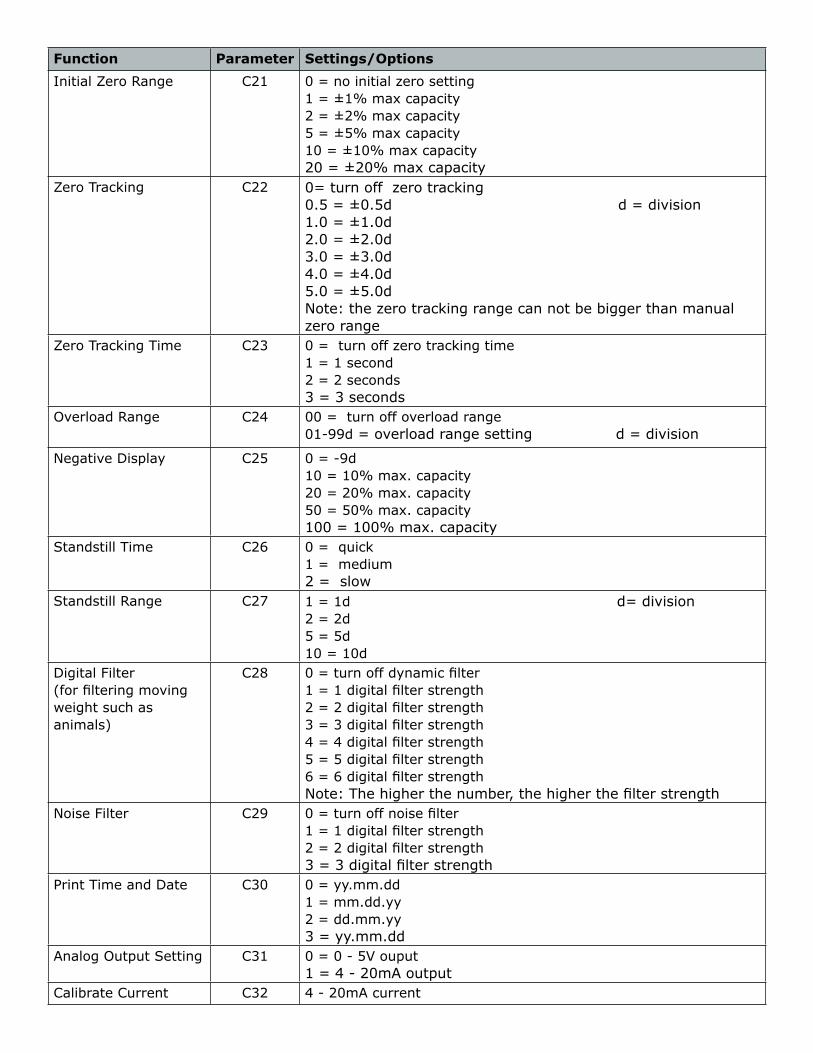
Function Parameter Settings/Options
Initial Zero Range C21 0 = no initial zero setting1 = ±1% max capacity2 = ±2% max capacity5 = ±5% max capacity10 = ±10% max capacity20 = ±20% max capacity
Zero Tracking C22 0= turn off zero tracking0.5 = ±0.5d d = division1.0 = ±1.0d2.0 = ±2.0d3.0 = ±3.0d4.0 = ±4.0d5.0 = ±5.0dNote: the zero tracking range can not be bigger than manual zero range
Zero Tracking Time C23 0 = turn off zero tracking time1 = 1 second2 = 2 seconds3 = 3 seconds
Overload Range C24 00 = turn off overload range01-99d = overload range setting d = division
Negative Display C25 0 = -9d10 = 10% max. capacity20 = 20% max. capacity50 = 50% max. capacity100 = 100% max. capacity
Standstill Time C26 0 = quick1 = medium2 = slow
Standstill Range C27 1 = 1d d= division2 = 2d 5 = 5d 10 = 10d
Digital Filter (for filtering moving weight such as animals)
C28 0 = turn off dynamic filter1 = 1 digital filter strength2 = 2 digital filter strength3 = 3 digital filter strength4 = 4 digital filter strength5 = 5 digital filter strength6 = 6 digital filter strengthNote: The higher the number, the higher the filter strength
Noise Filter C29 0 = turn off noise filter1 = 1 digital filter strength2 = 2 digital filter strength3 = 3 digital filter strength
Print Time and Date C30 0 = yy.mm.dd1 = mm.dd.yy2 = dd.mm.yy3 = yy.mm.dd
Analog Output Setting C31 0 = 0 - 5V ouput1 = 4 - 20mA output
Calibrate Current C32 4 - 20mA current
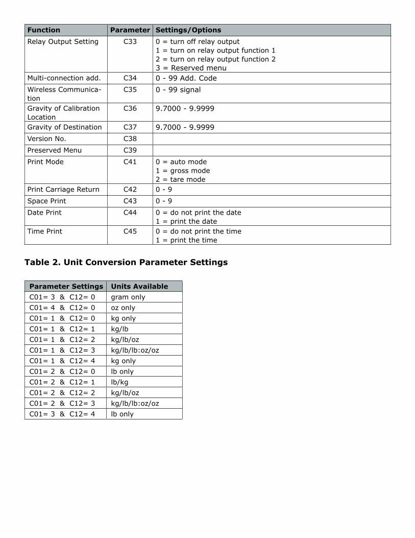
Function Parameter Settings/Options
Relay Output Setting C33 0 = turn off relay output1 = turn on relay output function 12 = turn on relay output function 23 = Reserved menu
Multi-connection add. C34 0 - 99 Add. CodeWireless Communica-tion
C35 0 - 99 signal
Gravity of Calibration Location
C36 9.7000 - 9.9999
Gravity of Destination C37 9.7000 - 9.9999Version No. C38
Preserved Menu C39
Print Mode C41 0 = auto mode1 = gross mode2 = tare mode
Print Carriage Return C42 0 - 9
Space Print C43 0 - 9
Date Print C44 0 = do not print the date1 = print the date
Time Print C45 0 = do not print the time1 = print the time
Table 2. Unit Conversion Parameter Settings
Parameter Settings Units AvailableC01= 3 & C12= 0 gram onlyC01= 4 & C12= 0 oz onlyC01= 1 & C12= 0 kg onlyC01= 1 & C12= 1 kg/lbC01= 1 & C12= 2 kg/lb/ozC01= 1 & C12= 3 kg/lb/lb:oz/ozC01= 1 & C12= 4 kg onlyC01= 2 & C12= 0 lb onlyC01= 2 & C12= 1 lb/kgC01= 2 & C12= 2 kg/lb/ozC01= 2 & C12= 3 kg/lb/lb:oz/ozC01= 3 & C12= 4 lb only

Table 3. Default Parameter Settings
Function Parameter Default Setting
Weighing Unit C01 1
Decimal Setting C02 0
Graduation Setting C03 1
Maximum Capacity C04 1000
Zero Calibration C05 0
Calibration C06 0
Restore Default C07 0
Warning Tone C08 1
Automatic Power Off
C09 0
Power Saving Mode C10 0
Hold Function C11 0
Unit Conversion C12 1
Upper Limit Alarm C13 000000
Lower Limit Alarm C14 000000
Inner Code Display C15
Set Date C16
Set Time C17
Communication Setting C18 0
Baud Rate C19 3 (9600)
Manual Zero Range C20 10
Initial Zero Range C21 10
Zero Tracking C22 0.5
Zero Tracking Time C23 1
Overload Range C24 9Negative Display C25 10
Standstill Time C26 1
Standstill Range C27 2
Digital Filter C28 0
Noise Filter C29 2
Print Time and Date C30 0
Analog Output Setting C31 1
Calibrate Current C32 4
Relay Output Setting C33 1
Multi-connection add. C34 0
Wireless Communica-tion
C35 6
Gravity of Calibration Location
C36 9.7936
Gravity of Destination C37 9.7936
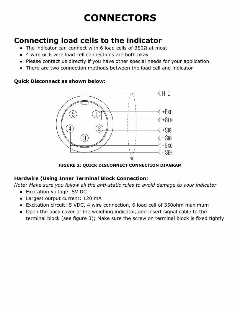
CONNECTORS
Connecting load cells to the indicator ● The indicator can connect with 6 load cells of 350Ω at most ● 4 wire or 6 wire load cell connections are both okay ● Please contact us directly if you have other special needs for your application. ● There are two connection methods between the load cell and indicator
Quick Disconnect as shown below:
FIGURE 2: QUICK DISCONNECT CONNECTION DIAGRAM
Hardwire (Using Inner Terminal Block Connection:Note: Make sure you follow all the anti-static rules to avoid damage to your indicator
● Excitation voltage: 5V DC ● Largest output current: 120 mA ● Excitation circuit: 5 VDC, 4 wire connection, 6 load cell of 350ohm maximum ● Open the back cover of the weighing indicator, and insert signal cable to the
terminal block (see figure 3); Make sure the screw on terminal block is fixed tightly
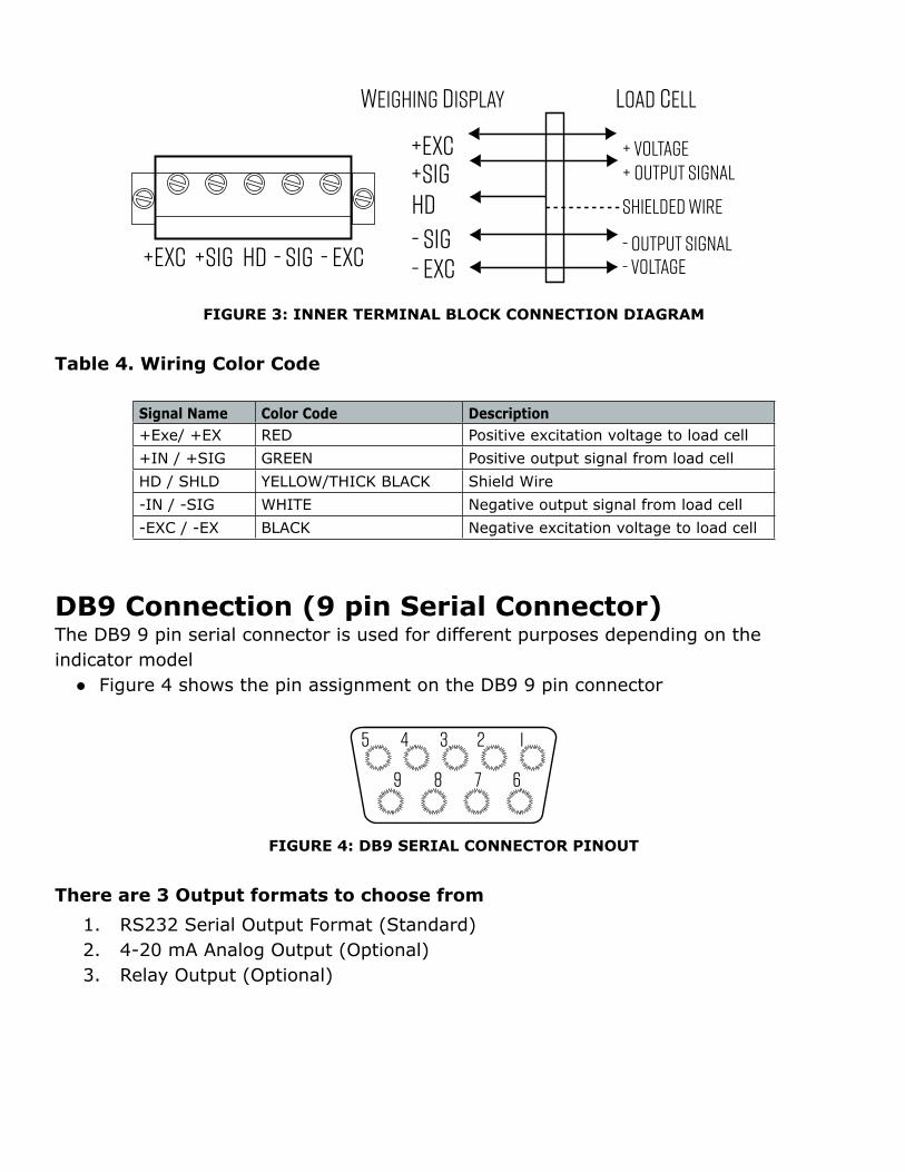
FIGURE 3: INNER TERMINAL BLOCK CONNECTION DIAGRAM
Table 4. Wiring Color Code
Signal Name Color Code Description+Exe/ +EX RED Positive excitation voltage to load cell+IN / +SIG GREEN Positive output signal from load cellHD / SHLD YELLOW/THICK BLACK Shield Wire-IN / -SIG WHITE Negative output signal from load cell-EXC / -EX BLACK Negative excitation voltage to load cell
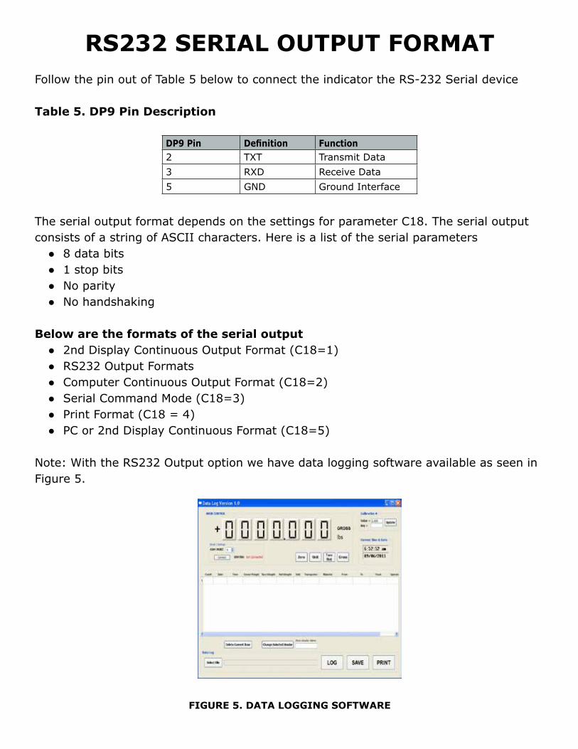
DB9 Connection (9 pin Serial Connector)The DB9 9 pin serial connector is used for different purposes depending on the indicator model
● Figure 4 shows the pin assignment on the DB9 9 pin connector
FIGURE 4: DB9 SERIAL CONNECTOR PINOUT
There are 3 Output formats to choose from
1. RS232 Serial Output Format (Standard)2. 4-20 mA Analog Output (Optional)3. Relay Output (Optional)
RS232 SERIAL OUTPUT FORMAT Follow the pin out of Table 5 below to connect the indicator the RS-232 Serial device
Table 5. DP9 Pin Description
DP9 Pin Definition Function2 TXT Transmit Data3 RXD Receive Data5 GND Ground Interface
The serial output format depends on the settings for parameter C18. The serial output consists of a string of ASCII characters. Here is a list of the serial parameters
● 8 data bits ● 1 stop bits ● No parity ● No handshaking
Below are the formats of the serial output ● 2nd Display Continuous Output Format (C18=1) ● RS232 Output Formats ● Computer Continuous Output Format (C18=2) ● Serial Command Mode (C18=3) ● Print Format (C18 = 4) ● PC or 2nd Display Continuous Format (C18=5)
Note: With the RS232 Output option we have data logging software available as seen in Figure 5.
FIGURE 5. DATA LOGGING SOFTWARE
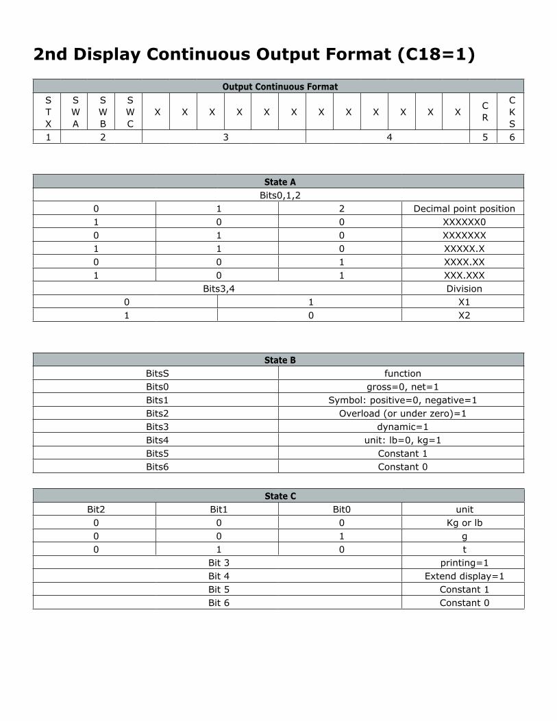
2nd Display Continuous Output Format (C18=1)
Output Continuous FormatSTX
SWA
SWB
SWC
X X X X X X X X X X X XCR
CKS
1 2 3 4 5 6
State ABits0,1,2
0 1 2 Decimal point position1 0 0 XXXXXX00 1 0 XXXXXXX1 1 0 XXXXX.X0 0 1 XXXX.XX1 0 1 XXX.XXX
Bits3,4 Division0 1 X11 0 X2
State BBitsS functionBits0 gross=0, net=1Bits1 Symbol: positive=0, negative=1Bits2 Overload (or under zero)=1Bits3 dynamic=1Bits4 unit: lb=0, kg=1Bits5 Constant 1Bits6 Constant 0
State CBit2 Bit1 Bit0 unit0 0 0 Kg or lb0 0 1 g0 1 0 t
Bit 3 printing=1Bit 4 Extend display=1Bit 5 Constant 1Bit 6 Constant 0
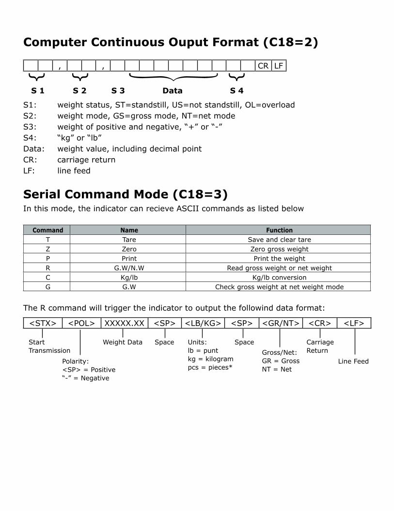
Computer Continuous Ouput Format (C18=2)
, , CR LF
{ { {
S 1 S 2 S 3 Data S 4
S1: weight status, ST=standstill, US=not standstill, OL=overloadS2: weight mode, GS=gross mode, NT=net modeS3: weight of positive and negative, “+” or “-”S4: “kg” or “lb”Data: weight value, including decimal pointCR: carriage returnLF: line feed
Serial Command Mode (C18=3)In this mode, the indicator can recieve ASCII commands as listed below
Command Name FunctionT Tare Save and clear tareZ Zero Zero gross weightP Print Print the weightR G.W/N.W Read gross weight or net weightC Kg/lb Kg/lb conversionG G.W Check gross weight at net weight mode
The R command will trigger the indicator to output the followind data format:
<STX> <POL> XXXXX.XX <SP> <LB/KG> <SP> <GR/NT> <CR> <LF>
StartTransmission
Polarity:<SP> = Positive“-” = Negative
Weight Data Space Units:lb = puntkg = kilogrampcs = pieces*
SpaceGross/Net:GR = GrossNT = Net
CarriageReturn
Line Feed
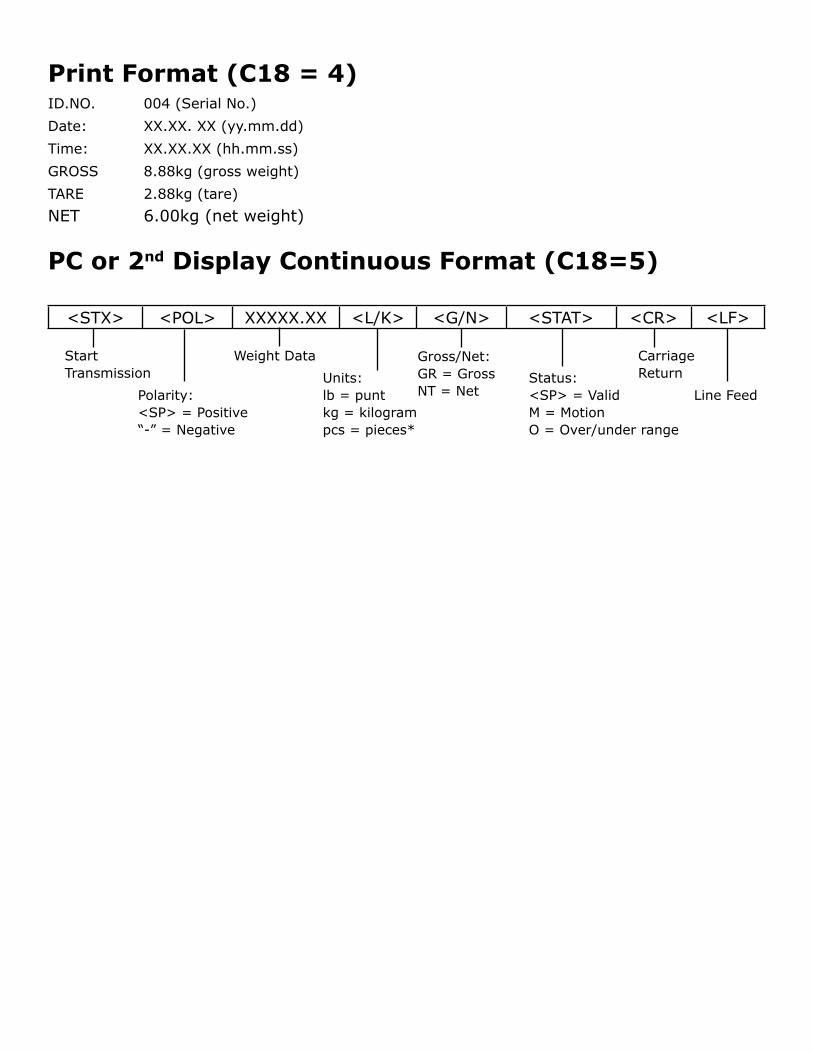
Print Format (C18 = 4)ID.NO. 004 (Serial No.)Date: XX.XX. XX (yy.mm.dd)Time: XX.XX.XX (hh.mm.ss)GROSS 8.88kg (gross weight)TARE 2.88kg (tare)NET 6.00kg (net weight)
PC or 2nd Display Continuous Format (C18=5)
<STX> <POL> XXXXX.XX <L/K> <G/N> <STAT> <CR> <LF>
StartTransmission
Polarity:<SP> = Positive“-” = Negative
Weight Data
Units:lb = puntkg = kilogrampcs = pieces*
Gross/Net:GR = GrossNT = Net
CarriageReturn
Line FeedStatus:<SP> = ValidM = MotionO = Over/under range
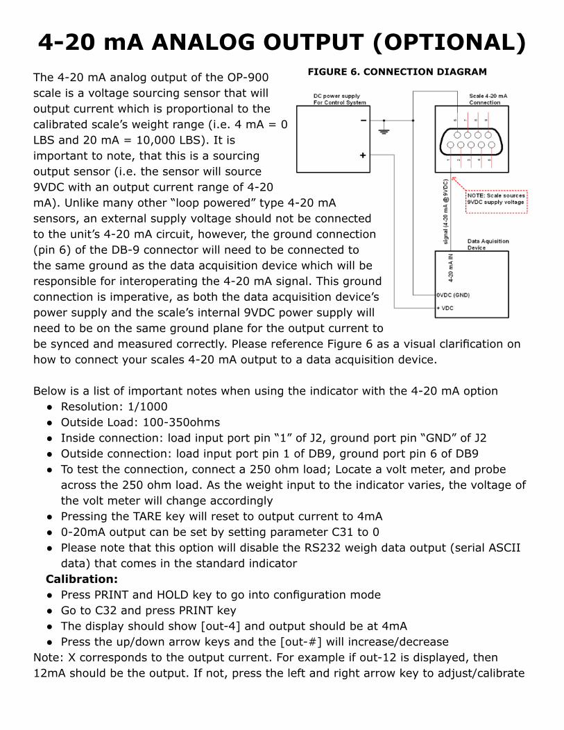
4-20 mA ANALOG OUTPUT (OPTIONAL)The 4-20 mA analog output of the OP-900 scale is a voltage sourcing sensor that will output current which is proportional to the calibrated scale’s weight range (i.e. 4 mA = 0 LBS and 20 mA = 10,000 LBS). It is important to note, that this is a sourcing output sensor (i.e. the sensor will source 9VDC with an output current range of 4-20 mA). Unlike many other “loop powered” type 4-20 mA sensors, an external supply voltage should not be connected to the unit’s 4-20 mA circuit, however, the ground connection (pin 6) of the DB-9 connector will need to be connected to the same ground as the data acquisition device which will be responsible for interoperating the 4-20 mA signal. This ground connection is imperative, as both the data acquisition device’s power supply and the scale’s internal 9VDC power supply will need to be on the same ground plane for the output current to be synced and measured correctly. Please reference Figure 6 as a visual clarification on how to connect your scales 4-20 mA output to a data acquisition device.
Below is a list of important notes when using the indicator with the 4-20 mA option ● Resolution: 1/1000 ● Outside Load: 100-350ohms ● Inside connection: load input port pin “1” of J2, ground port pin “GND” of J2 ● Outside connection: load input port pin 1 of DB9, ground port pin 6 of DB9 ● To test the connection, connect a 250 ohm load; Locate a volt meter, and probe
across the 250 ohm load. As the weight input to the indicator varies, the voltage of the volt meter will change accordingly
● Pressing the TARE key will reset to output current to 4mA ● 0-20mA output can be set by setting parameter C31 to 0 ● Please note that this option will disable the RS232 weigh data output (serial ASCII
data) that comes in the standard indicatorCalibration: ● Press PRINT and HOLD key to go into configuration mode ● Go to C32 and press PRINT key ● The display should show [out-4] and output should be at 4mA ● Press the up/down arrow keys and the [out-#] will increase/decrease
Note: X corresponds to the output current. For example if out-12 is displayed, then 12mA should be the output. If not, press the left and right arrow key to adjust/calibrate
FIGURE 6. CONNECTION DIAGRAM
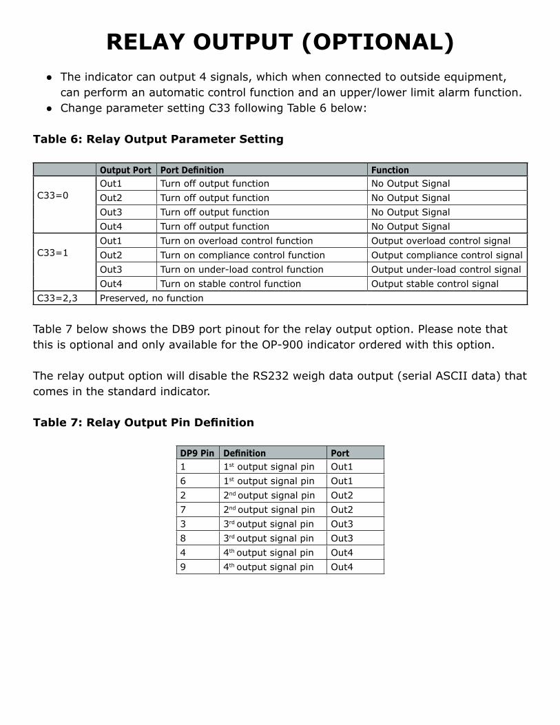
RELAY OUTPUT (OPTIONAL) ● The indicator can output 4 signals, which when connected to outside equipment,
can perform an automatic control function and an upper/lower limit alarm function. ● Change parameter setting C33 following Table 6 below:
Table 6: Relay Output Parameter Setting
Output Port Port Definition Function
C33=0Out1 Turn off output function No Output SignalOut2 Turn off output function No Output SignalOut3 Turn off output function No Output SignalOut4 Turn off output function No Output Signal
C33=1Out1 Turn on overload control function Output overload control signalOut2 Turn on compliance control function Output compliance control signalOut3 Turn on under-load control function Output under-load control signalOut4 Turn on stable control function Output stable control signal
C33=2,3 Preserved, no function
Table 7 below shows the DB9 port pinout for the relay output option. Please note that this is optional and only available for the OP-900 indicator ordered with this option.
The relay output option will disable the RS232 weigh data output (serial ASCII data) that comes in the standard indicator.
Table 7: Relay Output Pin Definition
DP9 Pin Definition Port1 1st output signal pin Out16 1st output signal pin Out12 2nd output signal pin Out27 2nd output signal pin Out23 3rd output signal pin Out38 3rd output signal pin Out34 4th output signal pin Out49 4th output signal pin Out4
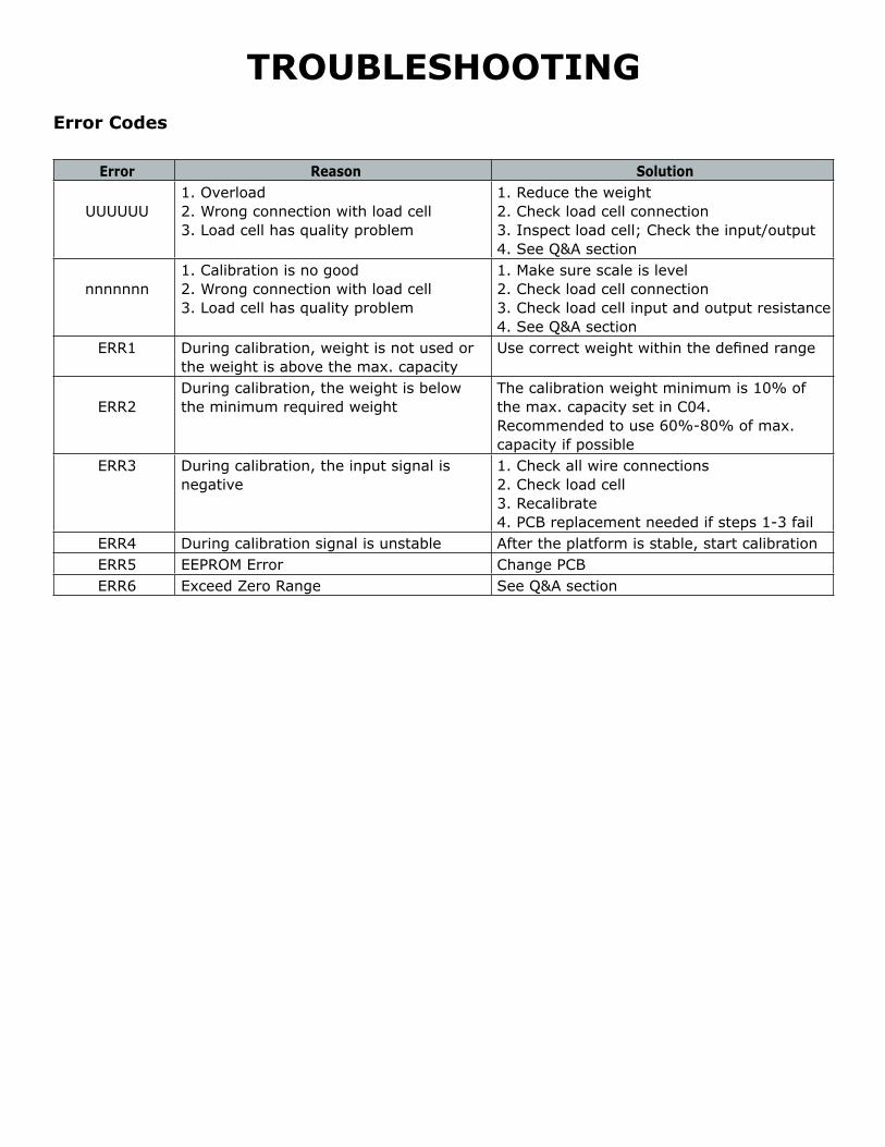
TROUBLESHOOTINGError Codes
Error Reason Solution
UUUUUU1. Overload2. Wrong connection with load cell3. Load cell has quality problem
1. Reduce the weight2. Check load cell connection3. Inspect load cell; Check the input/output4. See Q&A section
nnnnnnn1. Calibration is no good2. Wrong connection with load cell3. Load cell has quality problem
1. Make sure scale is level2. Check load cell connection3. Check load cell input and output resistance4. See Q&A section
ERR1 During calibration, weight is not used or the weight is above the max. capacity
Use correct weight within the defined range
ERR2During calibration, the weight is below the minimum required weight
The calibration weight minimum is 10% of the max. capacity set in C04. Recommended to use 60%-80% of max. capacity if possible
ERR3 During calibration, the input signal is negative
1. Check all wire connections2. Check load cell3. Recalibrate4. PCB replacement needed if steps 1-3 fail
ERR4 During calibration signal is unstable After the platform is stable, start calibrationERR5 EEPROM Error Change PCBERR6 Exceed Zero Range See Q&A section
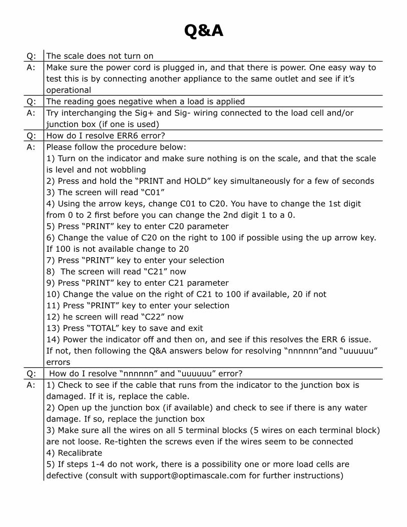
Q&A Q: The scale does not turn onA: Make sure the power cord is plugged in, and that there is power. One easy way to
test this is by connecting another appliance to the same outlet and see if it’s operational
Q: The reading goes negative when a load is appliedA: Try interchanging the Sig+ and Sig- wiring connected to the load cell and/or
junction box (if one is used)Q: How do I resolve ERR6 error?A: Please follow the procedure below:
1) Turn on the indicator and make sure nothing is on the scale, and that the scale is level and not wobbling2) Press and hold the “PRINT and HOLD” key simultaneously for a few of seconds3) The screen will read “C01” 4) Using the arrow keys, change C01 to C20. You have to change the 1st digit from 0 to 2 first before you can change the 2nd digit 1 to a 0.5) Press “PRINT” key to enter C20 parameter6) Change the value of C20 on the right to 100 if possible using the up arrow key. If 100 is not available change to 207) Press “PRINT” key to enter your selection8) The screen will read “C21” now9) Press “PRINT” key to enter C21 parameter10) Change the value on the right of C21 to 100 if available, 20 if not11) Press “PRINT” key to enter your selection12) he screen will read “C22” now13) Press “TOTAL” key to save and exit14) Power the indicator off and then on, and see if this resolves the ERR 6 issue. If not, then following the Q&A answers below for resolving “nnnnnn”and “uuuuuu” errors
Q: How do I resolve “nnnnnn” and “uuuuuu” error?A: 1) Check to see if the cable that runs from the indicator to the junction box is
damaged. If it is, replace the cable.2) Open up the junction box (if available) and check to see if there is any water damage. If so, replace the junction box3) Make sure all the wires on all 5 terminal blocks (5 wires on each terminal block) are not loose. Re-tighten the screws even if the wires seem to be connected4) Recalibrate5) If steps 1-4 do not work, there is a possibility one or more load cells are defective (consult with [email protected] for further instructions)

CONTACT USPlease e-mail [email protected] for any sales related question
Please e-mail [email protected] for any support related questions
Don’t forget to visit our website at:
optimascale.com