Embed Size (px)
Citation preview
MARYLAND STATE HIGHWAY ADMINISTRATION
Office of Construction
Construction Manual
O F F I C E O F C O N S T R U C T I O N
Construction Manual
2002 MD State Highway Administration Office of Construction
7450 Traffic Drive Hanover, Maryland 21076
Phone 443-572-5202 • Fax 410.410-787-8320 Last Updated:04/26/16
The wide left margin is provided for your remarks or notations.
The numbers in parentheses ( ) in the headings refer to Specification references.
i
INTRODUCTION
The 2002 edition of the Maryland State Highway Administration Construction Manual is a revised updated version of the Construction Manual dated June 12, 1998 to reflect the 2001 Standard Specifications, construction practices, techniques, and record keeping in effect today. The Construction Manual has been prepared as a guide for the standardization of construction practices statewide, and it should be utilized toward that objective. This is not a Contract Document and its content is not legally binding on any Maryland State Highway Construction Contract. The Construction Inspection Division encourages and requests that they be advised when errors or alternate construction methods are found. Approved revisions will be issued as the need arises. Each recipient of the manual is responsible for keeping the contents up to date. This manual is presented with the sincere belief that it will aid in maintaining the high quality of construction at SHA.
ii
1 PRELIMINARY ................................................................................................................ 1-1
AUTHORITY AND RESPONSIBILITY OF INSPECTORS (GP 5.07) ...................................................................................... 1-1 PROJECT ENGINEERS AND INSPECTORS (GP 5.07) ............................................................................................................ 1-1 PRECONSTRUCTION CONFERENCE ...................................................................................................................................... 1-5 NOTICE TO PROCEED (GP 8.02) ................................................................................................................................................ 1-6 PRELIMINARY PREPARATIONS (GP 5) ................................................................................................................................... 1-6 RIGHT-OF-WAY (107.03.07) .......................................................................................................................................................... 1-7 MOBILIZATION (108) ................................................................................................................................................................... 1-8 ENGINEER’S OFFICE CHECKLIST (103)................................................................................................................................. 1-9 ENGINEER’S OFFICE .................................................................................................................................................................. 1-9
Records (TC 7) ........................................................................................................................................................... 1-9
MAINTENANCE OF TRAFFIC (104) ........................................................................................................................................ 1-10 Records (104) ........................................................................................................................................................... 1-11
CONSTRUCTION STAKE OUT CHECKLIST (107) ............................................................................................................... 1-12 CONSTRUCTION STAKE OUT (107) ........................................................................................................................................ 1-12 REMOVAL AND DISPOSAL OF EXISTING BUILDINGS (102) ............................................................................................ 1-14 CLEARING AND GRUBBING INSPECTION CHECKLIST (101) ......................................................................................... 1-14 CLEARING AND GRUBBING (101) ........................................................................................................................................... 1-15 RECORDS AND DOCUMENTATION (TC 7) ........................................................................................................................... 1-17
FILING SYSTEM (TC 7) ......................................................................................................................................... 1-17 Plan Rack (TC 7) ...................................................................................................................................................... 1-19 REPORT AND RECORD PROCEDURES (TC 7) .................................................................................................. 1-19 FIELD OFFICE COMPUTER (TC 7) ...................................................................................................................... 1-20 DAILY CONSTRUCTION LOGS AND INSPECTOR’S DAILY REPORT (TC 7) ............................................. 1-20 PROJECT DIARY (TC 7) ........................................................................................................................................ 1-22 PROJECT RECORD BOOK (TC 7) ........................................................................................................................ 1-22 PROJECT LEDGER (TC 7) ..................................................................................................................................... 1-24 SKETCH BOOK (TC 7) ........................................................................................................................................... 1-24 Title Sheet (TC 7) ..................................................................................................................................................... 1-24 Signature Sheet (TC 7) ............................................................................................................................................. 1-25 Summary (TC 7) ....................................................................................................................................................... 1-25 Item Summary (TC 7) ............................................................................................................................................... 1-25
MEASUREMENT AND PAYMENT (TC 7) ................................................................................................................................ 1-26 DEGREE OF PRECISION (TC 7) ............................................................................................................................................... 1-26 MISCELLANEOUS FORMS AND REPORTS (TC 7) .............................................................................................................. 1-26
Work Commencement Notice (TC 7) ....................................................................................................................... 1-26
CERTIFIED PAYROLLS (TC 7) ................................................................................................................................................. 1-27 FORCE ACCOUNT WORK (TC 7) ............................................................................................................................................ 1-27 MATERIALS REPORTS .............................................................................................................................................................. 1-30
Materials Clearance .................................................................................................................................................. 1-30
2 GRADING ........................................................................................................................ 2-1
iii
GENERAL ....................................................................................................................................................................................... 2-1 AUTHORITY AND DUTIES OF INSPECTORS ......................................................................................................................... 2-3 EARTHWORK CHECKLIST (201) .............................................................................................................................................. 2-4 ROADWAY EXCAVATION (201) .................................................................................................................................................. 2-7 BORROW EXCAVATION (203) .................................................................................................................................................... 2-7 CHANNEL OR STREAM CHANGE EXCAVATION (Class 5) (202) ........................................................................................ 2-7 INSPECTION AND CONTROL OF GRADING OPERATIONS (200) ...................................................................................... 2-8 PRELIMINARY CHECKING OF PLANS AND OUTLINING OF WORK (200) ..................................................................... 2-8 EMBANKMENT FOUNDATION (204) ........................................................................................................................................ 2-9 DRAINAGE (300) ............................................................................................................................................................................ 2-9 UNSUITABLE MATERIALS (201) ............................................................................................................................................. 2-10 TEST ROLLING (204) .................................................................................................................................................................. 2-10 ROADWAY GRADING (201) ....................................................................................................................................................... 2-10 SHRINKAGE AND SWELL (201,203,204) ................................................................................................................................. 2-15 SUBGRADE (201,203,204) ............................................................................................................................................................ 2-16 METHOD OF MEASUREMENT (201,203,204) ......................................................................................................................... 2-17 TAMPED FILL (210)..................................................................................................................................................................... 2-18 TRIMMING EXISTING DITCHES (209) ................................................................................................................................... 2-19 TEST PIT EXCAVATION (205) ................................................................................................................................................... 2-19 REMOVAL OF EXISTING PAVEMENT, SIDEWALK, CURB, AND COMBINATION CURB AND GUTTER (206) ...... 2-19 REMOVAL OF EXISTING MASONRY (207) ............................................................................................................................ 2-20
3 DRAINAGE ...................................................................................................................... 3-1
SUBGRADE DRAINS (306) ........................................................................................................................................................... 3-1 UNDERDRAINS AND OUTLETS CHECKLIST (306) ............................................................................................................... 3-2 PIPE UNDERDRAINS AND OUTLETS (306) ............................................................................................................................. 3-2 PREFABRICATED EDGE DRAIN CHECKLIST (307).............................................................................................................. 3-5 PREFABRICATED EDGE DRAINS (307) .................................................................................................................................... 3-6 RIPRAP AND CONCRETE SLOPE PROTECTION CHECKLIST (312 & 310 ) .................................................................... 3-6
Riprap ......................................................................................................................................................................... 3-6 Concrete ...................................................................................................................................................................... 3-7 Riprap ......................................................................................................................................................................... 3-7 Concrete ...................................................................................................................................................................... 3-7 Riprap ......................................................................................................................................................................... 3-7 Concrete ...................................................................................................................................................................... 3-7
RIPRAP AND CONCRETE SLOPE PROTECTION (312 & 310) ............................................................................................. 3-8 PIPE CULVERT CHECKLIST (303) ............................................................................................................................................ 3-9 PIPE CULVERTS (303) ................................................................................................................................................................ 3-11 EROSION AND SEDIMENT CONTROL CHECKLIST (308) ................................................................................................. 3-15 EROSION AND SEDIMENT CONTROL (308) ......................................................................................................................... 3-16
iv
GABIONS CHECKLIST (313) ..................................................................................................................................................... 3-17 GABIONS (313) ............................................................................................................................................................................. 3-17 STRUCTURAL PLATE CULVERT CHECKLIST (304) .......................................................................................................... 3-18 MISCELLANEOUS STRUCTURES CHECKLIST (305) ......................................................................................................... 3-21 STONE MASONRY CEMENT RUBBLE MASONRY CHECKLIST (305) ............................................................................ 3-23 DRY RUBBLE MASONRY CHECKLIST (305) ........................................................................................................................ 3-24 GENERAL REQUIREMENTS (305) ........................................................................................................................................... 3-25 DEFINITIONS OF TERMS (305) ................................................................................................................................................ 3-26 CEMENT RUBBLE MASONRY (305) ........................................................................................................................................ 3-28 DRY RUBBLE MASONRY (305) ................................................................................................................................................. 3-29 BRICK MASONRY CHECKLIST (305) and (463) .................................................................................................................... 3-29 REPOINTED MASONRY CHECKLIST (305) (463) ................................................................................................................. 3-31 BACKFILL CHECKLIST (305) and (463) .................................................................................................................................. 3-32 CONCRETE DITCHES CHECKLIST (309) ............................................................................................................................. 3-35 CONCRETE DITCHES (309) ..................................................................................................................................................... 3-36
4 STRUCTURES ................................................................................................................ 4-1
GENERAL ....................................................................................................................................................................................... 4-1 PREPARATION FOR INSPECTION ............................................................................................................................................ 4-1 JOB SITE EXAMINATION ........................................................................................................................................................... 4-1 INSPECTION EQUIPMENT CHECKLIST ................................................................................................................................. 4-1 STRUCTURE EXCAVATION CHECKLIST (402) ...................................................................................................................... 4-2 SUBFOUNDATION INVESTIGATION (419) .............................................................................................................................. 4-7 SELECTED BACKFILL CHECKLIST (302 & 402) ................................................................................................................... 4-7 DRILLED HOLES IN EXISTING MASONRY CHECKLIST (406) .......................................................................................... 4-8 PILING (410) ................................................................................................................................................................................... 4-9 TEST PILES CHECKLIST (410) ................................................................................................................................................. 4-11 FOUNDATION PILES CHECKLIST (410) ................................................................................................................................ 4-14 PILE HAMMERS AND EQUIPMENT CHECKLIST (410) ..................................................................................................... 4-19 TYPES OF HAMMERS (410) ...................................................................................................................................................... 4-20 TIMBER STRUCTURES CHECKLIST (462) ........................................................................................................................... 4-22 CONCRETE STRUCTURES FORMWORK CHECKLIST (420) ........................................................................................... 4-24 FORMS FOR CONCRETE .......................................................................................................................................................... 4-24 TYPES OF FALSEWORK: .......................................................................................................................................................... 4-27 CHECKLIST OF FALSEWORK: ............................................................................................................................................... 4-30 REINFORCEMENT CHECKLIST (421) .................................................................................................................................... 4-32 PLACING CONCRETE (420) ...................................................................................................................................................... 4-36 PLACING CONCRETE CHECKLIST (420) .............................................................................................................................. 4-39 COLD WEATHER CONCRETE OPERATIONS (420) ............................................................................................................. 4-43
v
FINISHING CONCRETE (420) ................................................................................................................................................... 4-44 CURING CONCRETE (420) ........................................................................................................................................................ 4-44 CONCRETE BOX CULVERTS CHECKLIST (420) ................................................................................................................. 4-45 SUBSTRUCTURE CHECKLIST (420) ....................................................................................................................................... 4-46 CONCRETE BRIDGE DECK CHECKLIST (420) .................................................................................................................... 4-48 STAY-IN PLACE (SIP) FORMS (420) ......................................................................................................................................... 4-52 PRESTRESSED CONCRETE CHECKLIST (440) .................................................................................................................... 4-54 EXPANSION MATERIAL CHECKLIST (460) .......................................................................................................................... 4-56 DAMPPROOFING AND MEMBRANE WATERPROOFING CHECKLIST (422) ................................................................ 4-58 STEEL BEAMS—SIMPLE SPAN CHECKLIST (430) ............................................................................................................. 4-59 STEEL BEAMS—CONTINUOUS SPANS CHECKLIST (430) ................................................................................................ 4-61 STEEL STUD SHEAR DEVELOPERS CHECKLIST (431) ..................................................................................................... 4-63 ANCHORS, BEARINGS, AND EXPANSION PADS CHECKLIST (432) ............................................................................... 4-66 PNEUMATICALLY APPLIED MORTAR CHECKLIST (423) ................................................................................................ 4-69 METAL RAILING CHECKLIST (461) ....................................................................................................................................... 4-72 POROUS BACKFILL CHECKLIST (469) ................................................................................................................................. 4-73
5 PAVING ........................................................................................................................... 5-1
BASE AND SURFACE CONSTRUCTION GENERAL (501) ..................................................................................................... 5-1 AGGREGATE BASE COURSE (501) ........................................................................................................................................... 5-1 AGGREGATE BASE COURSE INSPECTION CHECKLIST (501) ......................................................................................... 5-2 BASE COURSE CONSTRUCTION GENERAL (501) ................................................................................................................ 5-4 BANK RUN GRAVEL BASE COURSE (501) ............................................................................................................................... 5-5 SAND AGGREGATE BASE COURSE (501) ................................................................................................................................ 5-6 STABILIZED AGGREGATE BASE COURSE ............................................................................................................................ 5-9 SURFACE COURSES (503, 04, 20, 21) ........................................................................................................................................ 5-11
SURFACE COURSE CONSTRUCTION—GENERAL ......................................................................................... 5-11
TACK COAT (504) ........................................................................................................................................................................ 5-11 MILLING AND GRINDING HMA CHECKLISTS (508) AND (509) ....................................................................................... 5-13 MILLING H.M.A. PAVEMENT (508) AND GRINDING H.M.A. PAVEMENT (509) ............................................................ 5-14 HOT MIX ASPHALT PATCHING (505) ..................................................................................................................................... 5-15 HMA PATCHES (505) ................................................................................................................................................................... 5-16 HOT MIX ASPHALT PAVING INSPECTION CHECKLIST (504) ......................................................................................... 5-18 HOT MIX ASPHALT (HMA) CONCRETE PAVEMENT (504) ............................................................................................... 5-21 PREPAVING CONFERENCE (CD 07220.500.04) (504) ............................................................................................................ 5-21 LINE AND GRADE CONTROL (504) ........................................................................................................................................ 5-24 HOT MIX ASPHALT (HMA) MIXTURE PLACEMENT (504) ............................................................................................... 5-25 ROLLING (504) ............................................................................................................................................................................. 5-29 DENSITY DETERMINATION (504) ........................................................................................................................................... 5-31
vi
SHOULDERS (504) ....................................................................................................................................................................... 5-31 COORDINATION OF OPERATIONS (504)............................................................................................................................... 5-32 INSPECTOR’S DUTIES (504) ..................................................................................................................................................... 5-32 CONCRETE PAVEMENT INSPECTION CHECKLIST (520&521) ....................................................................................... 5-37 PLAIN AND REINFORCED PORTLAND CEMENT CONCRETE PAVEMENT (520&521) .............................................. 5-41 MATERIALS (520&521) ............................................................................................................................................................... 5-42 PREPARATION OF PAVEMENT FOUNDATION .................................................................................................................... 5-42 PREPARATION OF THE BASE—SLIP FORM METHOD (520&521) .................................................................................. 5-42 PLACEMENT OF REINFORCEMENT (520&521) .................................................................................................................. 5-42 SLIP FORM PAVING (520&521) ................................................................................................................................................. 5-43 TIE BARS—SLIP FORM CONSTRUCTION (520&521) ......................................................................................................... 5-43 LOAD TRANSFER DEVICES (520&521) .................................................................................................................................. 5-44 PREPARATIONS FOR PAVING (520&521) ............................................................................................................................... 5-46 INSPECTION AT THE CONCRETE PAVING SITE (520&521).............................................................................................. 5-46 CHECKING EQUIPMENT—GENERAL (520&521) ................................................................................................................ 5-47 MECHANICAL FINISHING EQUIPMENT—GENERAL (520&521) .................................................................................... 5-47 PAVEMENT CONSTRUCTION (520&521) ............................................................................................................................... 5-49 PAVEMENT CONSTRUCTION—SLIP FORM (520&521) ...................................................................................................... 5-49 SLIP FORM CONSTRUCTION—EDGE TREATMENT (520&521) ...................................................................................... 5-50 JOINTS (520&521) ........................................................................................................................................................................ 5-50 CURING (520&521) ...................................................................................................................................................................... 5-51 PORTLAND CEMENT CONCRETE PAVEMENT REPAIRS (522) ....................................................................................... 5-53 CONCRETE PLACEMENT (522) ............................................................................................................................................... 5-56 COLD WEATHER CONSTRUCTION (520-522) ...................................................................................................................... 5-57 HOT WEATHER CONSTRUCTION (520-522) ......................................................................................................................... 5-58 CONTROL TESTS OF CONCRETE (902) ................................................................................................................................. 5-58 SEALING OF JOINTS (523) ........................................................................................................................................................ 5-59 PROTECTION OF PAVEMENT AND OPENING TO TRAFFIC (520-522) ........................................................................... 5-60
6 SHOULDERS .................................................................................................................. 6-1
GENERAL ....................................................................................................................................................................................... 6-1 BASE AND SURFACE FOR SHOULDERS ................................................................................................................................. 6-1 EARTH SHOULDERS (601) .......................................................................................................................................................... 6-1 EARTH SHOULDERS CHECKLIST (601) .................................................................................................................................. 6-1 HOT MIX ASPHALT CURB CHECKLIST (602) ........................................................................................................................ 6-2 HOT MIX ASPHALT CURB (602) ................................................................................................................................................ 6-2 CONCRETE CURB AND COMBINATION CURB AND GUTTER CHECKLIST (602) ........................................................ 6-3 CONCRETE CURB AND COMBINATION CURB AND GUTTER (609) ................................................................................ 6-5 CONCRETE SIDEWALK CHECKLIST (603) ............................................................................................................................ 6-8
vii
CONCRETE SIDEWALK (603) ................................................................................................................................................... 6-10 METAL TRAFFIC BARRIERS CHECKLIST (605) ................................................................................................................. 6-12 CONCRETE TRAFFIC BARRIER— CHECKLIST (604) ....................................................................................................... 6-13 TRAFFIC BARRIER (604-605) ................................................................................................................................................... 6-14 METAL TRAFFIC BARRIER—‘W’ BEAM (605) ..................................................................................................................... 6-14 CONCRETE TRAFFIC BARRIER (604) ................................................................................................................................... 6-15 CHAIN LINK FENCE CHECK LIST (607) ............................................................................................................................... 6-17 FENCE (607) .................................................................................................................................................................................. 6-18
7 LANDSCAPING ..............................................................................................................12-1
GENERAL ..................................................................................................................................................................................... 12-1 TOPSOIL AND SUBSOIL CHECKLIST (701)........................................................................................................................... 12-1 SALVAGED TOPSOIL AND SUBSOIL (701) ............................................................................................................................. 12-2 PLACING SALVAGED TOPSOIL AND SUBSOIL (701) .......................................................................................................... 12-3 FURNISHED TOPSOIL AND SUBSOIL (701) ........................................................................................................................... 12-3 SEEDING CHECKLIST (704-705) .............................................................................................................................................. 12-4 SEEDING MEDIAN AREAS (705) .............................................................................................................................................. 12-6 SEEDING ROADSIDE AREAS (705) .......................................................................................................................................... 12-6 TEMPORARY SEEDING (704) ................................................................................................................................................... 12-7 SOIL STABILIZATION MATTINGS (709) ................................................................................................................................ 12-7 SODDING CHECKLIST (708) ..................................................................................................................................................... 12-8 PLANTING CHECKLIST (710) .................................................................................................................................................. 12-9 PLANTING TREES, SHRUBS AND VINES (710) ................................................................................................................... 12-12 SEEDLING STOCK PLANTING (710) ..................................................................................................................................... 12-12 CARE OF EXISTING TREES AND SHRUBS CHECKLIST ................................................................................................. 12-13 SELECTIVE TREE TRIMMING (712) .................................................................................................................................... 12-14 SELECTIVE TREE FELLING (714)......................................................................................................................................... 12-14 SELECTIVE THINNING (713) .................................................................................................................................................. 12-15
8 TRAFFIC (801 TO 874)/UTILITIES (875 TO 899) ..........................................................13-1
GENERAL ..................................................................................................................................................................................... 13-1 TRAFFIC (SECTIONS 801 TO 874) ........................................................................................................................................... 13-1
Administration of Traffic Signal Work .................................................................................................................... 13-1
TCD Inspection Section ................................................................................................................................................................. 13-4 Traffic Control Signal Inspection Checklist ............................................................................................................. 13-4 SECTION 801 .......................................................................................................................................................... 13-4 SECTION 804 .......................................................................................................................................................... 13-5 SECTION 805 Conduit ............................................................................................................................................ 13-5 SECTION 806 .......................................................................................................................................................... 13-7 SECTION 807 .......................................................................................................................................................... 13-7 SECTION 810 .......................................................................................................................................................... 13-8
viii
SECTION 811 ........................................................................................................................................................ 13-10 SECTION 812 ........................................................................................................................................................ 13-11 SECTION 813 - SIGNS ON TRAFFIC SIGNAL PROJECTS .............................................................................. 13-11 SECTION 814 - SIGNALS .................................................................................................................................... 13-11 SECTION 816 - TRAFFIC SIGNAL CONTROLLERS AND CABINETS ......................................................... 13-12 SECTION 817 ........................................................................................................................................................ 13-13 SECTION 818 - SIGNAL STRUCTURES (Standards 818, 821) .......................................................................... 13-13 SECTION 819 ........................................................................................................................................................ 13-13 OVERHEAD SIGN STRUCTURES...................................................................................................................... 13-14 GENERAL .............................................................................................................................................................. 13-14
OVERHEAD SIGN STRUCTURES CHECKLIST .................................................................................................................. 13-14 Records ................................................................................................................................................................... 13-16
ELECTRICAL CONDUIT AND FITTINGS CHECKLIST .................................................................................................... 13-17 UTILITIES (SECTION 875 TO 899) ......................................................................................................................................... 13-18
CHECKLIST .......................................................................................................................................................... 13-18
POLICY ........................................................................................................................................................................................ 13-19 GENERAL ................................................................................................................................................................................... 13-19 PRELIMINARY ARRANGEMENTS ........................................................................................................................................ 13-20 INSPECTION AND CONTROL OF WORK ............................................................................................................................ 13-20
Plans and Permit ..................................................................................................................................................... 13-20 Work Orders ........................................................................................................................................................... 13-21 Schedule .................................................................................................................................................................. 13-21 Documentation ........................................................................................................................................................ 13-21 Test Pits .................................................................................................................................................................. 13-21 Delays ..................................................................................................................................................................... 13-22 Check of Work........................................................................................................................................................ 13-22 Protection of Services ............................................................................................................................................. 13-22 Cooperation between Parties .................................................................................................................................. 13-22 Changes Involving Third Party Work ..................................................................................................................... 13-22 Overruns ................................................................................................................................................................. 13-22 Betterment ............................................................................................................................................................... 13-22 Completion of Third Party Work ............................................................................................................................ 13-23 Completion of Work ............................................................................................................................................... 13-23 Bills ......................................................................................................................................................................... 13-23 Summary of Work Done ......................................................................................................................................... 13-23 Records: .................................................................................................................................................................. 13-23
CONSTRUCTION CHANGE ORDERS RELATIVE TO UTILITY WORK ........................................................................ 13-23
3/27/02 1-1
1 PRELIMINARY AUTHORITY AND RESPONSIBILITY OF INSPECTORS (GP 5.07) The effective management of a construction operation can only be achieved through a well-coordinated team effort. The Inspectors are vital members of that team, for without them there will normally be no direct involvement in the construction of the project by the designers or the Owner. The Inspector is the eyes and the ears of the Owner, whose authority and responsibility on the project are largely based upon that concept. It is not enough to leave the assurance of quality workmanship and materials entirely in the hands of the Contractor. The designer who was responsible for the determination of site conditions and for the preparation of the plans and specifications should also be available during the construction phase to provide field consultation and assist in quality control for the Owner.
PROJECT ENGINEERS AND INSPECTORS (GP 5.07) For clarification, the stated responsibilities and authorities apply to both Inspectors and Project Engineers. Any issues not easily resolved at the Inspector level should be immediately elevated to the Project Engineer who will either resolve or further elevate them to the District level.
The Inspector is responsible for protecting the Owner against defects and deficiencies in the work. When, in the judgment of the Inspector, the plans and specifications are not being properly followed and he/she has been unable to obtain compliance by the Contractor, the District should be notified so that appropriate action can be taken. Inspection must be performed during the progress of the work; inspection after completion defeats the purpose of providing quality control and assurance on the job, as many potential deficiencies must be detected during construction. Otherwise, they may be permanently covered. The result could be a latent defect, which might contribute to a structural failure or other disaster.
The Inspector, as project representative, should not direct, supervise, or assume control over the means, methods, techniques, sequences, or procedures of construction except as specifically called for in the project specifications. Instead, the Inspector should exercise authority on behalf of the Owner so that the project is constructed in accordance with the requirements of the Contract Documents.
The text in parentheses is the Specification Reference
Chapter
1 Category
1
3/27/02 1-2
Construction administration and quality control by the Contractor or quality assurance by the Owner should include continuous on-site inspection throughout construction by one or more competent, technically qualified, and experienced Inspectors. If there are several Inspectors on the project, subordinate Inspectors will be under the direct supervision of the Project Engineer. All communications with the District or designer should be through the Project Engineer. Inspectors are responsible for seeing that all details of the design drawings, shop drawings, reinforcement drawings, and similar documents that have been approved by the Engineer, are constructed in strict accordance with their respective requirements. In addition, each Inspector must see that all requirements of the Specifications have been met and that all workmanship and construction practices equal or exceed the standards called for in the Contract Documents. Neither the Project Engineer nor the Inspector has authority to change plans or Specifications, or to make their own interpretations, even though they may be qualified with both design and construction experience. If any question on interpretation arises, or if there is a disagreement with the Contractor on a technical matter, or if there appears to be any possibility of error or deviation from good construction practice that the Inspector notices, it should be brought to the attention of the Project Engineer and District Office immediately.
The Project Engineer and Inspectors can function effectively only when given certain specific authority. The following is a suggested scope of an Inspector’s authority and responsibility as recommended by the construction Division of the American Society of Civil Engineers:
The Project Engineer or Inspector is responsible for seeing that the work being inspected is in conformance with the Contract Documents. In the performance of assigned duties, the Inspectors would normally assume the following responsibilities:
1. The Inspector must become thoroughly familiar with the Contract Documents as they apply to the work to be inspected, and should review them frequently. Inspectors must be capable of immediately recognizing if the work they are inspecting conforms to the contract requirements.
2. If any material or portion of the work does not conform to the requirements, the Inspector should notify the Contractor, explain why it does not conform and record it on the Inspector’s Daily Report (IDR). If the Contractor ignores the notice and continues the operation, the Project Engineer should promptly advise the District Office.
3. As a member of the construction team, the Inspector must perform all duties in a manner that will promote the progress of the work. Inspectors should be familiar with the construction schedule and understand how the work, which they are inspecting, fits into the overall schedule. Completion of the work within the contract time is also important to the Owner.
3/27/02 1-3
4. The Inspector must avoid any inspection, testing, or other activity that could be interpreted as a responsibility of the Contractor; otherwise, the Owner’s position may be jeopardized in the event of a dispute or claim. This applies particularly to the Contractor’s quality control program for testing and inspecting the Contractor’s materials and workmanship as a part of his contractual responsibility.
5. When an Inspector is assigned to any operation, that operation should be covered as long as the work is proceeding. If the original Inspector must leave, another Inspector should take over. This applies particularly to work that will not be observed again such as driving piles, laying pipe in a trench, and placing concrete.
6. The IDR should include a thorough and accurate recording of the day’s activities. The Inspector must remember that, in the event of contract disputes, the IDR may assume legal importance.
7. When tests are performed on-site, they should be performed efficiently and carefully, samples must be carefully handled and protected, and test failures reported to the Contractor without delay.
8. Inspections and tests should be prompt and timely
a) Materials should be checked when they are delivered to the project.
b) Preparatory work such as cleaning inside the forms, fine grading of footing areas, winter protection for concrete, and so on should be promptly checked to minimize delay to subsequent operations.
c) Work should be inspected as it progresses. For example, postponing the inspection of the placing of reinforcing and other embedded items until they are 100 percent complete does nothing but delay progress.
d) An Inspector must be available at all times to provide prompt inspections and a decision when required. Likewise, the Contractor is expected to give adequate notice to the Inspector when the work will be ready for inspection.
9. If a specification is determined to be unenforceable, it should be immediately brought to the attention of the District Office.
10. Anticipate and resolve problems to maintain work progress.
11. Unacceptable work should be recognized in the early stages and reported to the Contractor before it develops into an expensive and time-consuming operation. The notification should be confirmed in writing when necessary.
3/27/02 1-4
An Inspector who is thoroughly familiar with the contract requirements can recognize these situations almost immediately.
12. Occasionally, a problem may arise that the Project Engineer is unable to handle alone. This should be reported to the District Office for prompt action. Unresolved problems can sometimes develop into critical situations and claims.
13. The Inspector should thoroughly investigate the situation and its possible consequences. For example, a request by the Contractor to be permitted to begin placing concrete at one end of a long footing while the crew is completing the reinforcing at the far end could be given consideration and not be automatically denied. If necessary, the Inspector should seek advice from the Project Engineer.
14. When work is to be corrected by the Contractor, the Inspector should follow it up daily. Otherwise, corrections may be forgotten or the work covered over.
15. The Inspector should stand behind any decision made on issues concerning the Contractor’s work.
16. In the course of his work, the Inspector must be capable of differentiating between those issues that are essential and those that are not. Issues and concerns must be prioritized while applying common sense.
17. The Inspector should be able to recognize safety hazards in the work being inspected to protect employees, the public, and the environment from consequences of potential accidents. Action must be taken to correct dangerous conditions immediately. It is the Inspector’s responsibility to report unsafe conditions to the Project Engineer. Refer to the appropriate Construction Directive in Category 100 Preliminary.
18. The Inspector has a responsibility to be alert and observant. Any situation that may delay the completion of the project should be reported to the Project Engineer. The Project Engineer will report it to the District Office.
The Project Engineer and Inspectors must be delegated certain authority to perform the required duties properly. The close working relations with the Contractor demand it. The Inspector should use the given authority when the situation demands it, and should not abuse it. In addition, the Contractor is entitled to know what the specific authority of the Inspector is, and when the work is not proceeding in an acceptable manner.
3/27/02 1-5
1. The Inspector should have the authority to verify approval of materials and workmanship that meet the Contract requirements.
2. In accordance with Contract General Provisions, GP 5.07 the Inspector is authorized to inspect all work performed and all material furnished. The Inspector is not authorized to revoke, alter, or waive any requirements of the contract nor is he/she authorized to approve or accept any portion of the complete project. The Inspector will have the authority to reject material and suspend work until questions at issue can be referred to and decided by the Project Engineer. When a Contractor is ordered to suspend an active operation, it becomes a costly item, particularly if expensive equipment and material such as concrete are involved. If the suspension of work is not justifiable by the terms of the Contract, the Contractor has just cause to be compensated for cost incurred. The Inspector cannot be familiar with all the details of the Contract nor with all the other contractual relationships; therefore, it is imperative that any suspension be totally justified and be brought immediately to the attention of the District Office. The Inspector should keep proper, detailed documentation explaining all the issues related to any suspension of work and its ultimate resolution.
3. The Inspector does not have the authority to approve deviations from the Contract Documents. This can only be properly accomplished with District approval.
4. The Inspector should not require the Contractor to furnish more than that required by the plans and specifications.
5. The Inspector should not under any circumstances attempt to direct the Contractor’s work; otherwise, the Contracting firm may attempt to be relieved of its responsibility under the Contract.
6. Instructions should only be given to the Contractor’s superintendent or foreman.
These guidelines are general in nature and some variations can be expected depending upon District procedures, project complexity, efficiency of the Contractor, and experience of the inspection staff.
PRECONSTRUCTION CONFERENCE A preconstruction conference between the Contractor’s representative on the project and the Project Engineer is required. A discussion of the project, specifications, unusual conditions, Contractor’s plan and schedule of operation, and other pertinent items is conducive to better job understanding. An understanding should be reached as to how, and with whom the Project Engineer’s representatives will communicate within the Contractor’s organization during inspection of the work. If utility
3/27/02 1-6
adjustments or removals are involved in the project, the utility representatives must attend the part of the conference that would involve that phase of the work.
At this meeting, the site for the project field office should be determined, as well as sites for storage of material and equipment. All such facilities on SHA right-of-way must be approved by the Administration.
Any controversy between the Contractor and the Project Engineer that cannot be resolved at the field level, in accordance with the controlling Contract Documents and established policies, should be referred to the District Engineer in written form.
All important instructions from the Project Engineer to the Contractor must be either given in writing or confirmed in writing. These instructions will be made part of the official project file.
NOTICE TO PROCEED (GP 8.02) The Deputy Administrator/Chief Engineer/Operations will send to the Contractor a “Notice to Proceed” (NTP) with the work. A copy of this letter will be forwarded to the District Engineer who will, in turn, notify the Project Engineer. The date of issue of this letter is the date to be recorded and used in all reports as date of “Notice to Proceed.” The date stipulated as the on or before date which work is to begin is used in accordance with the specifications for determining the start of “contract time.”
PRELIMINARY PREPARATIONS (GP 5) Before beginning work on any contract, the Project Engineer should make certain that all of the following items applicable to the contract are on site.
1. Complete contract drawings, including any revisions that have been authorized.
2. Cross-sections.
3. Standard Specifications, Supplemental Specifications, and Invitation for Bids (IFB).
4. Reference materials.
5. Right-of-Way plats, options, entry agreements, entry rights obtained under the immediate possession law, and a record of properties under condemnation.
6. Plans for adjustments to, or relocations of, any utilities that may be affected.
7. Notice to Proceed Letter. (NTP)
8. Material test equipment.
3/27/02 1-7
9. Material test reports and approved sources of supply.
10. Sketchbook, report forms, office supplies and field books.
11. Surveying notes and equipment.
12. Pertinent correspondence.
RIGHT-OF-WAY (107.03.07) On all projects that require the acquisition of land, plats are prepared to show the boundaries of the land to be acquired. The Office of Real Estate handles acquisition of this land; the necessary rights may be obtained by fee simple title, by easement, by formal agreement, or by condemnation proceedings, as determined by the nature of the requirements or existing conditions. The Project Engineer should be familiar with the general nature of each type of acquisition and should keep informed of the status of all right-of-way on the project. The Administration cannot always obtain clear title and full possession of all parcels before construction work begins. Good public relations, as well as legal aspects, make it important that the Contractor respect private property rights and not enter any property until proper right-of-way clearance has been obtained.
The right-of-way lines shown on the plats define the area of fee simple acquisition. Easement lines enclosing hatched area define those portions to which certain rights of use are acquired but to which a full title is not taken. These easements may be temporary, with all rights reverting to the property owner upon the fulfillment of certain conditions, or they may be perpetual and remain permanently with the SHA. Areas required for supporting slopes, which do not have a parallel drainage at the outer limits, will be acquired under a revertible easement. For urban projects, the fee simple taking will include areas needed for curb backing or sidewalk backing, but areas needed for supporting slopes will generally be acquired under a temporary easement.
A representative of the Office of Real Estate will visit the property to apprise damages that will result from property taking and construction of the project; open negotiations with the property owner; and, if agreement can be reached, write an option that stipulates the compensation to be paid, the date when the Administration will take possession, and any special conditions that have been agreed upon.
After the property owner has signed the option, it is submitted to the Administration for action and, upon acceptance, becomes binding upon both parties. The Project Engineer will receive a copy of the portion of the option that covers the terms of possession and any special conditions. Read the copy carefully, since the terms may involve certain work not shown on the plans but required under the agreement such as construction of an entrance.
3/27/02 1-8
When agreement cannot be reached as to fair market value of the property taken and resulting damage to any remaining portion, Maryland law provides for a hearing before the Board of Property Review. If either party is dissatisfied with the findings of the Board, the law further provides for appeal to the appropriate court. The appeal will result in regular condemnation proceedings. This action does not affect the right of entry to the land, but the Administration cannot obtain possession of any buildings until after the case for damages is tried before a jury, the amount of compensation is set, and the property is vacated.
Under the right of eminent domain, the State is empowered to acquire land for highway construction by condemnation. Condemnation, however, is normally a last-resort procedure and is used only after every reasonable effort has been expended to obtain an amicable settlement, or when for special reasons a clear title cannot be obtained otherwise. Under certain amendments to the State Constitution, Title VIII was enacted to provide a faster means to obtain possession of land for construction purposes. This law provides, upon the recording of plats containing certain information and upon the payment to the property owner or into court, for immediate possession of the property to be acquired. Although the land is available for construction when these conditions have been met, buildings must not be disturbed, access must not be cut off, and facilities used by the occupants must not be disrupted.
When the needed right of way involves another party, such as a governmental agency or a public utility, these may be acquired through execution of a formal agreement between the Administration and the other party. Such an agreement, for example with a railroad, usually provides for continued joint use of the property and sets forth the responsibilities of each party in such matters as maintenance, cost incurred, protective devices, and damages arising from accidents. The Project Engineer will receive a copy of the agreement and should become thoroughly familiar with the conditions it contains. In most cases, the State need acquire only the portion lying within the right-of-way and easement lines.
MOBILIZATION (108) Mobilization consists of all work and operations necessary to assemble and set up the project. This mobilization includes moving personnel and equipment to the project site and establishing the Contractor’s Offices, buildings, and other facilities required by the Contract Documents.
Mobilization also includes cost of required insurance and bonds. This lump sum item is paid for by allowing 50 percent of the lump sum price to be payable on the first progress estimate and by prorating the remaining 50 percent over the next five progress estimates.
3/27/02 1-9
ENGINEER’S OFFICE CHECKLIST (103) See that
1. The office site is located within the vicinity of the job.
2. Telephone service, electric power, sewage disposal facilities, and water supply are available.
3. The site is easily accessible even in wet weather; and required parking is provided.
See that
1. The Contractor properly maintains the office.
2. The initial and progress payments are made on the specified basis.
See that
1. The Office is removed from the site and the site is restored as required.
ENGINEER’S OFFICE Specifications Section 103 gives the requirements for the Engineer’s Office, which is furnished by the Contractor. The office must be ready for use five days before other work is started. No payment on an estimate can be allowed until the office meets all requirements of the Specifications.
Records (TC 7) The Specifications give the basis of payment for the field office. Records should include the date on which the Project Engineer took possession of the office, an inventory of the equipment furnished and installed on that date, and the serial number of each of the larger items of equipment, such as the fire-resistant filing cabinet.
MAINTENANCE OF TRAFFIC CHECKLIST (104)
See that
1. Locations for temporary construction and detours are correct as shown on the Traffic Control Plan (TCP).
2. The Office of Materials and Technology (OMT) has approved the materials.
3. Necessary traffic control devices are available.
4. Approved TCP is approved and implemented.
Before Construction
During Construction
After Construction
Before Construction
3/27/02 1-10
See that
1. Temporary structures and roadways are constructed in accordance with the requirements of the Contract Documents.
2. Records pertaining to measurements, weight tickets, test reports, and other documentation of quantities and materials used are kept up-to-date.
3. Temporary and permanent roads and structures, as well as those under construction, are maintained in conformance with the Contract Documents.
4. Traffic Control Devices are reviewed continuously.
5. The Contractor’s Traffic Manager (TM) implements the TCP, maintains an up to date TCP and provides a copy of any approved changes to the TCP to the Project Engineer.
6. The TM on a regular basis monitors the condition of the route traveled through work areas.
See that
1. Temporary structures and roadways are removed and restored to proper condition.
2. Measurements and cross sections are taken as required to document payment for quantities of materials removed.
3. Measurements, drawings and computations are made and entered in the sketch book to document quantities of items.
MAINTENANCE OF TRAFFIC (104) This work consists of maintaining traffic, vehicular and pedestrian, on or along any transportation facility as specified in the Contract Documents.
The lump sum item Maintenance of Traffic does not pay for furnishing, placing, or using materials for temporary structures and roadways when detouring traffic or for the material’s eventual removal. Payment for such materials is usually made on the basis of unit prices for items that were included in the contract specifically for these purposes.
The Contract will include a TCP developed by the Administration. When implemented, this plan assures the safety or motorists, pedestrians, and construction workers during the highway construction project. The Contractor may develop a TCP to be used instead of the Administrations TCP. If the Contractor develops his own TCP, it must be submitted with a written request to the District Engineer at least
During Construction
After Construction
3/27/02 1-11
20 days before starting any work that will affect vehicular or pedestrian traffic. The District Engineer must approve the Contractor’s TCP in writing before it can be implemented. (Note: Federally funded projects that are non-Certified Acceptance also require Federal Highway Administration approval.)
The Contractor shall assign to the project an employee experienced in all aspects of traffic control that will serve as TM. That person’s name and emergency home telephone number must be submitted to the Project Engineer for approval 10 days before starting any work on the project, and they should be displayed in plain view in the field office window.
Once the TCP is in place, the Project Engineer or designated subordinate will review the plan with the TM. Elements of the review will include the safety and efficiency of traffic movement through the construction zone and whether traffic control conforms to the TCP and to the manual on Uniform Traffic Control Devices. With concurrence of the Project Engineer, the TM may make minor adjustments to the TCP in the field as conditions warrant. Significant changes to the TCP, as required by field conditions, will be submitted by either the TM or the Project Engineer or both to the District Engineer for approval before they are put into practice. The Inspector is responsible to monitor the Contractor’s surveillance and maintenance of traffic control devices and safety through the work area. Regular monitoring includes inspection during non-working hours, such as nighttime and holidays.
The lump sum price for the item, Maintenance of Traffic, covers the cost of providing for safe passage of traffic over temporary construction as well as through the area of the construction work or around it on detour roads. Additional items applicable to maintaining traffic will be measured and paid for at the unit price bid for the pertinent item.
The item, Maintenance of Traffic, is paid for by allowing, on the progress estimates, percentages of the total lump sum that was bid for the item. The percentage of the total item to be allowed for any month should be approximately the same as the percentage of the total value of the contract amount earned during that month.
Records (104) Records should include not only the quantities of all materials used in the construction and maintenance of temporary roadways and structures, but also the approval of the source of each material, the test authenticating its acceptability and proper installation, and its conformity to the TCP. Documentation may also include photographic records of the traffic controls in effect during various stages of construction and may show periodic changes in traffic patterns through the work zone.
3/27/02 1-12
CONSTRUCTION STAKE OUT CHECKLIST (107) 1. Become familiar with the Plans, noting location of benchmarks and control
points. If any questions arise, consult survey books as listed on the front of the Plans.
2. Check the center line or base line stake out through the length of the project.
3. Check the control points. Note any that have been destroyed or missing.
4. Have the District Survey Party reset any missing points before construction commences if any parts of the center line or controls are missing.
5. Run a set of levels to verify the benchmarks on the Plans.
1. Check right-of-way, Limit of Disturbance, and Wetland Stakeout before clearing and grubbing commences.
2. Check some work of the Contractor’s survey to ensure that the layout is correct.
3. Check slope stakes for grade and alignment at both toe and top of the slope.
4. Check the stake out periodically to ensure that stakes have been replaced as needed.
5. Check sections of cuts and fills periodically to ensure that proper cross sections are obtained.
1. Run 10% check of cross sections to confirm that design section has been met and to check on excavation quantities.
CONSTRUCTION STAKE OUT (107) The Contractor is responsible for setting construction stakes. However, the Administration is obligated first to furnish an original stake out center line and to provide appropriately placed benchmarks. The SHA survey parties should not do any of the Contractor’s required work since a special item for construction stake out is provided in the Contract to pay the Contractor for this work.
The Inspector should see that the Contractor employs qualified personnel who are skilled and equipped to stake out the project to the proper lines, grades, slopes, and cross sections in accordance with the requirements of the Plans. The Inspector should also check grading operations to see that the proper slopes and roadway typical sections are being constructed.
Before Construction
During Construction
After Construction
3/27/02 1-13
Contractor’s Responsibilities: Using the above-noted stake out work as a control and base line, the Contractor is required to do all other survey and stake out work necessary for the satisfactory completion of the project. This includes setting and marking stakes to define the right-of-way and/or easement line as required for construction of the project and as may be requested by abutting property owners. The Contractor may also be required to furnish reference and control points for both alignment and grade so that the utility companies or other agencies working within the project limits can properly locate and correlate their work with the road project. Refer to the specifications for details of these requirements. The Inspector should spot check any such work to ensure its reliability.
Slope Stakes: The setting of slope stakes to outline the limits of cuts and fills is also the responsibility of the Contractor. Set each stake by trial and error, or successive approximations, until its proper location is determined. Never permit the setting of slope stakes by using lateral distances scaled from plotted cross sections of the work. Slope stakes should be marked on the side facing the roadway with the cut or fill running from the top of the stakes to finished profile grade, and marked on the side away from the roadway with the offset distance to center line. Offset distances should be marked to the nearest tenth of a foot. The Inspector should spot check the location of some stakes and “sight them in” to see that they give a smooth alignment that corresponds to the lay of the ground.
Slope stake spacing will vary with the type of terrain. For average terrain an interval of 50 feet will usually suffice, but somewhat closer intervals may be required in rough terrain.
Slope stakes may be set before the clearing and grubbing operation and may be used as a guide for the limits of this work. The work area, however, must extend far enough beyond the slope stakes to allow for the rounding of slopes and the construction of adjacent longitudinal drainage ditches. Where there is very heavy growth the Contractor may prefer to clear before setting the slope stakes. In this case, scaling for the plotted cross sections, the lateral distance to be cleared at each station and setting clearing limit stakes at these distances is permitted.
As the work progresses, additional slope stakes are set at fractional depths of the cuts and fills to check that the slopes are being constructed at the specified ratio.
Grade Stakes: The Contractor sets grade stakes on the center line, edge of pavement, or shoulder of the roadway after the rough grading operations are substantially complete. This step enables the Inspector and the Contractor to check the grade before the fine grading or capping operations begin. The Inspector should check often as work progresses to see that the project is being constructed satisfactorily according to the designed alignment, profile, and cross section. Particular attention should be paid at cross roads and at each end of the project to make sure that the work ties in on both vertical and horizontal alignment.
3/27/02 1-14
The Inspector should check stakes for location, alignment, length, and grade of culverts before installation to ensure the drainage condition matches the design. If the drainage must be altered to the extent that construction will not be confined to the right-of-way or easement shown on the plat, the Project Engineer must notify the District Engineer, who will request, a revision of the right-of-way.
Grade stakes for paving operations are covered in the paving section under Base and Surface Construction, and more complete details of the entire construction surveying procedure are given elsewhere in this manual, including records to be kept and a checklist.
Flagging. The Contractor is responsible to place flagging continuously throughout wetland areas.
REMOVAL AND DISPOSAL OF EXISTING BUILDINGS (102) The Specifications provide for removing and disposing of existing buildings as specified in the Contract Documents.
Salvageable material from such operations becomes the property of the Contractor, who must remove it from the site.
All structures included in this bid item are identified by number, and a lump sum price is bid for the removal and disposal of all of them. No measurement is necessary. The Contractor, however, is required to submit a breakdown of the lump sum bid price for Removal and Disposal of Existing Buildings identifying the price bid for each unit by number. If any of the buildings are eliminated from the Contractor’s removal operations, the price bid for them can thus be deducted from the lump sum payment for the entire item.
CLEARING AND GRUBBING INSPECTION CHECKLIST (101) 1. Review Contract Documents and right-of-way agreements for special
requirements, and Erosion and Sediment Control Plan (see Section 308 of Specifications).
2. Check clearing limits.
3. See that clearing limits and wetlands are clearly marked.
4. Designate trees or growth to be left standing.
5. See that trees specially selected for preservation are adequately protected.
6. Enter date and sign in the sketch book first date on which operation is worked.
Before Clearing and Grubbing
3/27/02 1-15
1. Make sure work conforms to Contract Documents.
2. Maintain protection for selected trees.
3. Meet specifications for removal requirements and maximum stump heights.
4. Dispose of removed materials away from the job. File all applicable permits at job site before any burning.
5. Observe fire regulations and file necessary permits.
6. Perform indicated salvage.
7. Clean debris, rubbish, and dead wood from areas outside the clearing limits but within the right-of-way.
8. Complete IDR about personnel, equipment, and location of work.
1. Have damaged trees repaired.
2. Have disposal areas put in presentable condition.
3. Record completion of item in sketch book with date, signature, and note of whether the item was completed satisfactorily.
CLEARING AND GRUBBING (101) Before beginning grading operations, all materials not to be incorporated in the road, such as vegetation, fences, stumps, debris, and minor incidental structures not otherwise provided for, must be removed from the construction area. All work involved in this operation is combined into one item, “Clearing,” that covers the removal of materials above the ground surface. “Grubbing,” covers removal of imbedded materials. This also includes cleaning and partial clearing of the area outside the actual construction space but within the right-of-way or easement lines. It does not include the removal of buildings, other major structures, or unsuitable materials, such as muck or root mat, which require excavation procedure and which are included with certain excavation items.
Before clearing and grubbing begin, the Contractor should review the Special Provisions and the right-of-way agreements to determine whether they include special requirements concerning the handling and disposal of removed materials. In some areas right-of-way agreements may require extra work, such as salvaging of cordwood or timber, which is not included in the bid price. In these cases it will be necessary to arrange for new items to cover this work or for performance by force account.
The Specifications, Section 101, define limits of the areas to be cleared and grubbed, and the Project Engineer should see that these limits are clearly marked in the field.
During Clearing and Grubbing
After Clearing and Grubbing
Special Agreements
Clearing Limits
3/27/02 1-16
The preservation of trees and shrubs is generally desirable so all concerned should take care that trees outside the construction area are not damaged. Special clearing limits may also be required for interchanges where existing vegetation between ramps or within a loop is to be preserved. Cross sections should be checked to see if any areas lend themselves to saving existing trees within the normal clearing limits. If there is any question of the advisability of saving certain trees, the District Engineer should obtain the recommendation of Environmental Design.
Areas that lie outside the clearing limits but within the right-of-way or easement lines are to be cleared of all rubbish and fallen wood. In addition, all dead trees and any stumps, either dead or alive, are to be cut flush with the ground. This work must be done without injury to the live growth that is to remain and, in some cases, it may be necessary to fell the dead trees in sections. Injured plants are highly susceptible to further damage by insects or disease; the Contractor is responsible to repair and treat any plants injured. The Specification, GP-7.11 Preservation and Restoration of Property, describes responsibility of the Contractor in this matter. If branches of trees overhang the area to be occupied by the surfacing and shoulder, they are to be cut and trimmed properly to maintain the required clearance height of 16 feet. Advice about tree surgery or inspection of completed work may be obtained from the Office of Environmental Design through the District Engineer.
Trees selected for preservation should be adequately protected. Such tree protection is the Contractor’s responsibility and is to be provided at no additional cost.
The Contractor should dispose of materials removed under this item, and the cost is included in the price bid. In some cases, organic materials suitable for topsoil are to be salvaged under the terms of another item. Where salvage is indicated, the Contractor shall do the necessary stockpiling. Where burning is practiced, the Project Engineer should see that the Contractor observes the applicable laws and regulations of Federal, State, and local government agencies having jurisdiction. All applicable permits must be on file at the job site before any burning commences. Regulations of the Department of Forests and Parks relative to forest protection apply to these contracts and are the specifications. Stumps, roots, and other debris are sometimes disposed of on private property by arrangement between the Contractor and the property owner. A copy of the written agreement between the Contractor and property owners must be on file at the job site along with any other application permits (such as Erosion and Sediment Control- Water Resource Administration). In no case should debris be visible from the highway. Stumps shall never be buried in the road embankments. Grading should not be permitted in any area until the clearing and grubbing of that area has been satisfactorily completed. The Specifications give details as to permissible heights of stumps that can be allowed to remain and where complete removal is required. The Inspector’s duty is to be fully familiar with and to see that work is performed in accordance with these requirements.
Clean Up Limits
Preserved Items (101/GP 7.01)
Disposal of Material
3/27/02 1-17
Fences within the right-of-way should be removed carefully and placed on the abutting property if this action is part of the right-of-way agreement or is requested by property owners.
Stream and channel change areas shall also be cleared as specified before excavating or refilling.
Records: Clearing and grubbing is usually paid for on a lump sum basis, and detailed measurements are not required. At the close of each day, the Inspector should submit a report to the field office showing the stations between which the work is being performed and the right and left boundaries, main line, spur, and other locations. This information will then be entered in the field records.
RECORDS AND DOCUMENTATION (TC 7) FILING SYSTEM (TC 7) The filing system should be an orderly arrangement that will make all correspondence, construction reports, field records, materials test reports, right-of-way information, and utilities status quickly available. Practically all matters handled in the field office will fall into one of these groups and the subdivisions so formed can be expanded to fit a contract of any magnitude or complexity. The general principles outlined here are applicable whether the material is kept in file folders, loose-leaf binders, or envelopes. Job records must always be available for reference or inspection by District Office, OOC, CID, and FHWA personnel. More than one person should be able to produce these records.
The following grouping of file items was prepared for a typical contract. The list should be expanded or reduced, as necessary, to fit a particular job. The files should be kept in numerical order with an appropriate index preceding the file or on the face of the drawer.
Project Correspondence--(specific contract information)
Contractor’s Correspondence--(initiated by the Contractor)
General Correspondence
Inspector’s Daily Reports (IDRs)
Minority Business Enterprise (MBE), Disadvantaged Business Enterprise (DBE), Women’s Business Enterprise (WBE)
Daily Logs
Item Ledger
Fences
Stream Changes
3/27/02 1-18
Sketch Book (Item Summary Book)
Weekly Time Report
Project Diary
Project Record Book
Monthly Summary of Time Charges
Contractor’s Current Estimate
Estimate Worksheets
Affirmative Action Plan (AAP)
Subcontractor Approvals
Field Sketch File
Transition Data
Source of Supplies
Material Approvals
Materials Received
Material Test Reports
Soil Compaction--(Pipe)
Soil Compaction--(Embankment)
Soil Compaction--(Subgrade)
Base Compaction
Gradation Reports
Concrete Mix Designs
Concrete Plant Reports
Concrete Cylinder Test Reports
Asphalt Mix Designs
3/27/02 1-19
Asphalt Plant Reports
Right-of-Way (R/W) Correspondence
Right-of-Way (R/W) Plats
Utility Files (one for each known utility company)
Revisions
Change Orders (COs)
Working Drawings—Correspondence
Traffic Control Plan (TCP)
Payrolls (Contractor)
Administration Equipment File
Plan Rack (TC 7) A plan rack is required by Specifications for storing certain project data that cannot be placed in the filing cabinet. The type and number of plans that pertain to the project will depend on the magnitude of that particular project. Small and infrequently used drawings may be preserved in better condition by folding and storing in the filing cabinet. A typical job will have the following drawings, and where bulk or frequent use makes folding impractical, these should be kept on the plan rack.
Construction Plans for the Project
Cross Sections
Right-of-Way Plats
Public Utility Plats
Working Drawings
REPORT AND RECORD PROCEDURES (TC 7) As the work on the project progresses, the Project Engineer must record the accomplishments and events of each day on the Daily Log and enter supplemental information in the Project Diary and Project Record Book. The Project Engineer or their representative must also record the quantities of work performed and their value in the Project Ledger. Information from these daily records is complied and submitted in the current progress estimate.
The start of work on a project must be reported promptly by the Project Engineer.
3/27/02 1-20
FIELD OFFICE COMPUTER (TC 7) On all projects field office computers will be called for in the Invitation for Bids (IFB). The computer will keep most of the field office records. It will always be necessary to retain all original documents, especially the IDR. All field personnel will continue to fill out an IDR. The information from the IDRs will be compiled on the computer. The computer program is designed to provide a daily log, an item ledger, progress percentages, and progress estimates on any given day of the month.
DAILY CONSTRUCTION LOGS AND INSPECTOR’S DAILY REPORT (TC 7) To facilitate field office work and compilation of Daily Logs, each Inspector will prepare, in duplicate, an IDR, submitting the original to the field office and retaining the duplicate. It will include dimensioned sketches and quantity computations as well as the other data indicated, and as such becomes an original and permanent document. Pertinent information such as instructions, problems, unusual weather conditions, noncompliance, reasons for delay, and idle equipment, should be noted. Supplemental documentation forms may be used for sketches or comments. Upon completion of the project, the original IDRs are to be submitted to the District Office for retention with the Sketch Book and other project records.
The Daily Construction Log should be filled out in accordance with the following detailed instructions. Unless directed otherwise, the office person should submit logs at the end of each week, in groups covering the week’s work.
1. “Location”—Show the number or road name on the second line followed by either the locale or the approximate limits of work.
2. “Description”—Give the type of work being done, such as Grade, Drain, and Pave Divided Highway, or Rehabilitation of Existing Road, Resurfacing, or Bridges Over (whatever), etc.
3. “Wind”- Give the intensity, which is more important than direction.
4. “Soil or Grade Condition” and “Tide or Stream Stage”- Indicate which term applies by scratching out the term that is not applicable, and then fill in the proper description notation.
5. “Temperature”—Note the temperature extremes for the day. This is particularly important since temperature controls phases of the work.
6. “Remarks”—Explain the reason for each type of delay when it first occurs (revisions, verbal orders, etc.) Note: The use of the Partial Shutdown Construction Log is permissible when the subject contract is on partial shutdown and no work is being done. The information noted in Section 1-5 above will still be required.
3/27/02 1-21
7. “Labor”—Include the operators of all equipment, listing each under the appropriate classification. Hours shown for labor are not the hours per individual worker, but are the total hours for the number of workers indicated.
8. “Equipment”—List all types on the job, in use and idle. If space is available, use separate lines for idle equipment. Otherwise, working and idle equipment of the same type may be shown on the same line. “Hours” will be the total for the number of pieces of equipment indicated. Whenever equipment hours are shown in the “Idle” column, a “key number” must be inserted in the last column, using a different number to indicate each different reason for idleness. These reasons must then be explained under “Remarks” and identified by the appropriate “key number,” as for example: a. Broken down, b. Utility or Right-of-Way delay, c. Dead storage, not in use.
9. “Delays”—At the bottom of the “Remarks” Section, check the proper box for the duration of the delay. For details of the delay, refer below to the date when this delay first occurred. On the log for the first day of each type of delay, give an explanation for the delay under “Remarks.” No checkmark will indicate that there is no delay.
10. "Paving Record" - List the item number for each entry.
a. "Thickness"--Note the thickness specified for the unit of payment for the type of course being placed.
b. "Description" - List items such as "Hot Mix Asphalt" and “Reinforced Concrete”. Identify the location of the paving.
c. The "Ratio" of materials "Used" to “Required" should be computed to at least two decimal places. In the last column under "Remarks," show the accumulated totals of quantities of any particular paving item used and required and their ratios to date.
11. "Work Done and Material Used"—Use the lower left-hand corner to describe the work done, other than paving, and identify it by item number, description, location, and quantity completed and where pertinent, note the quantity of material used.
12. “Inspection Staff”—Note each worker’s assignment or category of work.
13. “Signatures”—Date the two signatures in the lower right-hand corner according to when they were signed, which may not always be the same as the date of the log.
3/27/02 1-22
Use the reverse side for extended remarks, explanations, and sketches. Write the word “over” in large letters at the lower left-hand corner of the sheet whenever the reverse side is used, so that attention will be called to the fact.
PROJECT DIARY (TC 7) The Project Engineer will also keep a diary to record all pertinent items not otherwise documented in other project records. The diary should be concise and should include all important information and verbal instructions relative to the contract on that particular day. It should not contain routine matters that can be found in other records, such as numerical records of quantities or work completed or similar data. The diary should be a hardback, permanently bound book, and the entries in it should begin and end with the project, not with the calendar year. Therefore, it is preferable to use a book, which does not have spaces of predetermined size and is not divided off and marked for specific days of the year. The diary is not a personal item but is a project document. If properly detailed, it will often prove invaluable in settling claims. At the close of the project, the diary must be turned in to the District Office along with the Sketch Book and other permanent project documents.
Matters that should be noted are the following:
1. Unusual weather conditions, which should be explained in greater detail than shown in the logs. If possible, give quantitative figures to indicate excessive amounts of rainfall or excessively high winds.
2. All verbal instructions to the Contractor should give the date, specific person to whom the instructions were given, nature of the instructions, and whether there were any objections or comments on the part of the Contractor’s representatives. Important verbal instructions should later be confirmed in writing.
3. Salient developments concerning any important matter pertaining to the contract.
4. Dates on which the Contractor’s major equipment is moved onto or away from the job.
5. Any incident, regardless of how trivial it appears at the time, which may later become pertinent in connection with any claim the Contractor might present.
All entries should be dated and signed. No space should be left to allow for alterations.
PROJECT RECORD BOOK (TC 7) The Project Engineer is responsible for thoroughly documenting all construction data for the project. He or she will keep a hardback permanently bound field book identified as a “Project Record Book.” One or more books will be kept for each
3/27/02 1-23
project as required by its size. It is recommended that the file marked Project Record Book contain a single record book, or in the case of multiple record books, an index of the record books in use, by number. These books must be kept in the fireproof file until the completion of the contract, at which time they will be turned in to the District Office along with the Sketch Book and other project records.
Records to be kept will include but will not be limited to all data similar to the following:
1. Checks of the Contractor’s survey and layout work, including alignment, grade, and slope stakes for roadways.
2. Checks of alignment, skew, span lengths, and critical elevations for structures.
3. Records of samples of materials taken and sent in from the field to the laboratory.
4. Results of compaction tests for embankment, subgrade, base and surface courses, trench backfill, and shoulders. For tests such as these on which complete reports of all test data, computations, and results are kept on other special forms, it will be necessary to record in the Project Record Book only the results of the tests and not the detailed data and computations from which the results were derived.
5. Checks of thickness or depth of courses such as subbase, base and surface courses, HMA pavement courses, and stabilized shoulders.
6. Results of slump tests.
7. Results of air content tests.
8. Records of concrete cylinder tests.
9. Results of straight-edging of pavements and curbs.
10. Records of checks that have been made on the number, size, and placement of reinforcing bars in structures.
11. Records of temperatures of heated concrete when placed and of temperatures maintained during curing and within heated enclosures.
12. Records of dates on which structure forms were stripped and cured and/or heating was discontinued.
13. Records of any other job tolerances, yields, checks, or tests not otherwise documented.
3/27/02 1-24
14. Where checks and test results have indicated inadequacies, what corrective measures were taken, together with the results obtained.
All information noted above shall be completely identified by dates, times, locations by station and off-set, adequate descriptions, notations concerning results, and the identity of the person observing or performing the operation. It is intended that the Project Record Book supplement rather than replace the project diary, which must still be kept by the Project Engineer and ultimately filed in the District Office.
PROJECT LEDGER (TC 7) The Project Engineer will also maintain a Project Ledger in which the quantity entries will be made on the date on which the work is performed. The quantity will be entered from the IDR into the Project Ledger under the proper item.
SKETCH BOOK (TC 7) After the contract has been completed, the Project Engineer will submit to the District Office a Sketch Book that will reflect the “As Built” plans and that will completely substantiate quantities previously allowed the Contractor on current estimates and will also provide the basis for preparing the final estimate. Work on the Sketch Book should proceed concurrently with contract progress and, as each element of work is completed, the necessary final measurements, sketches, and computations should be made so that summarization and assembly will be the only Sketch Book work remaining after the contract is accepted for Maintenance. The completed Sketch Book should be submitted to the District Office within 15 days after final acceptance of the contract.
At the start of work the Project Engineer will assemble a blank Sketch Book containing a supply of the necessary forms. The sheets, as completed, should be kept in a loose-leaf binder in orderly sequence and made available to the District Office for checking progress and conformity with standard procedures. The completed Sketch Book will include a title sheet, signature sheet, summaries, sketch and computation sheets, invoices, delivery tickets, and cross-sections as described in more detail below.
Title Sheet (TC 7) The headings are self-explanatory and should be filled in as the information becomes available. The letters “P” or “C” will be used with close down entries to distinguish between partial and complete shut downs. In the case of a partial shut down, the number of days to be shown are those not accounted for otherwise. For example, if the calendar dates listed indicate a total elapsed time of 10 days, but if 4 of these days have been accounted for on the monthly time charge summary under such classifications as prorated work days, Sunday, or no charge, then the difference of 6 should be entered as the number of days for which the job was under partial shut down. In the case of a complete shut down, the number of days to be shown should agree with the elapsed calendar time. The title sheet, when completely filled in, will be used as the first sheet of the Sketch Book.
3/27/02 1-25
Signature Sheet (TC 7) Each Sketch Book will contain a printed or typed signature sheet for listing the Project Engineer and each Inspector’s name assigned to the project. On the same line as their names, Inspectors will sign full signatures. This sheet will be placed in front of the Sketch Book. To identify documents, ledgers, and Sketch Book pages, each Inspector ever assigned to the project will sign the page.
Summary (TC 7) A summary of quantities will be prepared, with item number, description, and unit entered in the proper columns. The total quantity computed for each item will be transferred from the item summary sheet to the column headed “Field”. The District will fill in the column headed “District” the column after checking the Sketch Book computations. The District column will be used to prepare the final estimate. The two columns should agree; if different, however, a recheck must be made for errors or omissions. If an item was not used, the space should not be left blank but should have “NOT USED” entered. The word “deleted” may be used only when the item has been deleted by a Change Order. Items added to the contract will be shown in numerical order and in the same way as original proposal items, except that the Change Order number will also be shown.
On Federal aid contracts, the quantity summary must be prepared so that item quantities eligible for Federal participation can be determined. This step may require a supplemental summary sheet, as some contracts involve separate Federal agreements and different degrees of participation. The construction limits of Federal participation may also differ from the contract limits; in this case, it will be necessary to separate the field measurements and quantity calculations into participating and nonparticipating work.
The District Office will be furnished with the estimate sheet portion of the Federal Highway Administration agreement that designates the items and quantities eligible for Federal aid. Station limits of Federal aid are shown on the contract drawings and must be observed when determining quantities for Federal participation. If these limits are not shown on the contract drawings, the Project Engineer will notify the District Office so that it may secure the information from the appropriate agency.
Item Summary (TC 7) Each item should be summarized by tabulating on an appropriate form. Station, lane, and whether on centerline, to right or to left should describe the location of the work. Entries should be made in some logical order, such as station sequence, to facilitate checking and to avoid omission or duplication. Additional description, or reference to the computation sheet, from which the quantity was taken, may be given in the second column. A quantity entry should be made of the total shown for each computation sheet or segment of the work, and identification of this entry with the corresponding calculation must be readily apparent.
3/27/02 1-26
There is a specific form to be used for Hot Mix Asphalt items, which are paid for on a weight basis as shown on the delivery tickets. The date, stations, lane description, ticket numbers, and weight should be tabulated in the proper columns. If the day’s work was performed at different locations or in different lanes, separate entries should be made for each location described. Tickets should be grouped within each defined location and the day’s total for that group listed in the column. Delivery tickets usually express the unit of payment.
Sketch and Computation Sheet A sketch must be prepared for each portion of work in which the item is paid for on the basis of measured units. The method of computation must be clearly indicated so that both method and arithmetic can be readily checked. A final answer without the computations will not be accepted. All sketches and computations must be initialed, checked and corrected by project personnel before being entered in the Sketch Book and forwarded to the District Office.
Sketching and dimensioning will vary with the complexity of the data and must always clearly convey all necessary information. Tracings made of plan sheets often prove advantageous as a base for showing surface measurement items such as seeding or sodding. Area outlines may be sketched in their relation to the construction base line, field measurement dimensions added, and the area calculations placed on the tracings. These sheets may be folded, or placed in an envelope and bound into the Sketch Book.
MEASUREMENT AND PAYMENT (TC 7) Specification TC, Section 7, Payment, establishes the method of measurement and basis of payment for all items of work. In addition, the specification for each item includes the requirements for that particular item of work.
DEGREE OF PRECISION (TC 7) A general rule for the degree of precision required is the higher the cost of the unit being measured, the higher the degree of precision required. A list of typical contract items and the degree of precision to be observed in field measurements and computations is given in the following tabulation. While this list does not include all the items that may be found in the contract IFB, the field measurements and computations for the items listed are typical examples of the procedures that should be used in determining final quantities. Refer to the Specifications for details of each specific item.
MISCELLANEOUS FORMS AND REPORTS (TC 7) Work Commencement Notice (TC 7) After the Contractor receives the “Notice to Proceed” and work has begun on the project, the Project Engineer will fill out the Work Commencement Notice and forward copies to the designated officials.
3/27/02 1-27
CERTIFIED PAYROLLS (TC 7) Refer to the appropriate Construction Directive establishing the procedures governing content and format for certified payrolls required on construction contracts.
FORCE ACCOUNT WORK (TC 7) Where the method of payment by Supplemental Agreement is impracticable, the Administration may require the Contractor to do additional work on a force account basis. The rate of wages for all anticipated labor and equipment used on force account work shall be submitted by the Contractor to the District Engineer and agreed on in writing before beginning such work. The Project Engineer and/or their representative must keep accurate records of all force account work and, at the end of the day, must compare records of the work with the Contractor’s representative. Force Account indicates the information required to complete the form day by day.

3/27/02 1-28
Item Field Measurements to nearest
Results Computed to nearest
Earthwork
Roadway Excavation:
Class 1 0.1 feet 0.1 cu. yd.
Class 1-A 0.1 feet 0.1 cu. yd.
Class 2
0.1 feet
0.1 cu. yd.
Structure Excavation:
Class 3
0.1 feet
0.1 cu. yd.
Class 4
0.1 feet
0.1 cu. yd.
Channel or Stream Change Excavation:
Class 5
0.1 feet
0.1 cu. yd.
Borrow Excavation
0.1 feet
0.1 cu. yd.
Base Courses:
Base Courses
0.1 feet 0.1 sq. yd.
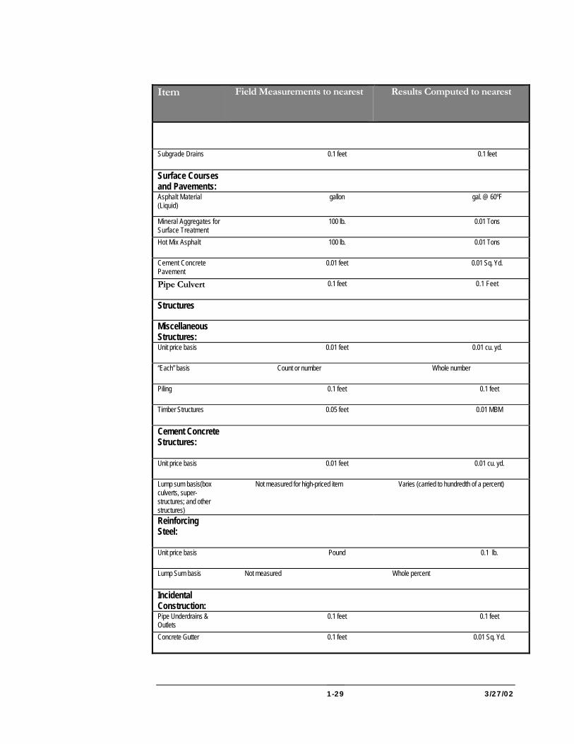
3/27/02 1-29
Item Field Measurements to nearest
Results Computed to nearest
Subgrade Drains 0.1 feet 0.1 feet
Surface Courses and Pavements:
Asphalt Material (Liquid)
gallon gal. @ 60ºF
Mineral Aggregates for Surface Treatment
100 lb. 0.01 Tons
Hot Mix Asphalt 100 lb. 0.01 Tons
Cement Concrete Pavement
0.01 feet 0.01 Sq. Yd.
Pipe Culvert 0.1 feet 0.1 Feet
Structures
Miscellaneous Structures:
Unit price basis 0.01 feet 0.01 cu. yd.
“Each” basis Count or number Whole number
Piling 0.1 feet 0.1 feet
Timber Structures 0.05 feet 0.01 MBM
Cement Concrete Structures:
Unit price basis 0.01 feet 0.01 cu. yd.
Lump sum basis(box culverts, super- structures; and other structures)
Not measured for high-priced item Varies (carried to hundredth of a percent)
Reinforcing Steel:
Unit price basis Pound 0.1 lb.
Lump Sum basis Not measured Whole percent
Incidental Construction:
Pipe Underdrains & Outlets
0.1 feet 0.1 feet
Concrete Gutter 0.1 feet 0.01 Sq. Yd.

3/27/02 1-30
Item Field Measurements to nearest
Results Computed to nearest
Concrete Curb and Combination Curb
0.1 feet 0.1 feet
Concrete Sidewalk 0.1 feet 0.01 Sq. Ft.
Traffic Barriers:
Contract unit price 0.1 feet 0.1 feet
Contract lump sum Not measured Whole percent
Topsoil: (Placing; Furnished & Placed)
1.0 feet 1.0 Sq. Yd.
Seeding 1.0 feet 1.0 Sq. Yd.
Mulching 1.0 feet 1.0 Sq. Yd.
Seeding & Mulching Slopes
1.0 feet 1.0 Sq. Yd.
Solid Sodding 0.1 feet 0.1 Sq. Yd.
Soil Stabilization Matting
0.1 feet 0.1 Sq. Yd.
MATERIALS REPORTS Duplicate copies must be made of all physical tests and results of compaction tests, cylinder reports, and gradation. Copies of the above must be sent to OMT as soon as there are a sufficient number of tests to report.
When materials are sent to the laboratory for testing the applicable form must accompany the sample. A record of this transmission will be entered into the Project Record Book.
The Project Engineer will also receive a materials report form #10 from OMT that records the results of the tests of sampled material and indicates whether or not the material meets Specifications and is approved for use.
Instructions and procedures for sampling will be found in the Materials Manual.
Materials Clearance Construction Directive establishes the basis of acceptance and expediting material clearance procedures for construction contracts.
3/27/02 2-1
2 GRADING GENERAL Grading is the work involved in constructing the roadbed on which a subbase, base course, and surface is to be built. It includes the excavation required to bring the roadway to grade, provide ditching for draining surface water, change the channels or existing streams, and provide additional material from borrow pits. It also includes hauling excavated materials, placing, shaping and compacting embankments, and shaping the subgrade to the required cross section. Grading operations usually alter the existing drainage pattern so that a new pattern must be established and facilities provided to collect and carry the water. There is a close relationship between grading and drainage. Throughout the grading operation water must continue to drain safely and effectively to avoid floods or ponding that may cause damage, to avoid erosion, and to control sediment.
This section discusses construction operations necessary to complete the roadbed to the subgrade. The subgrade is the top graded surface on which the base course, pavement, and shoulders are constructed. In the case of a project involving stage construction, the subgrade for the second stage may be the final or top surface required by the first-stage contract.
The basic operations of highway construction are excavating both roadway and borrow material and placing, compacting, and finishing of excavated material in the embankments or fills. Because one of these operations can hardly be carried on without the other they are generally inspected and controlled as a single grading operation. The largest part of the Grading Inspector’s duties and responsibilities is to inspect and control the excavation and embankment work.
The Specifications for the grading operation are in two separate Sections: Roadway Excavation, which is measured for payment, and Embankment, which is not measured for payment. Since the two operations are carried on concurrently, using combined forces and equipment for the completed grading operation, they will be discussed together in this manual.
The Project Engineer and the Grading Inspector should be thoroughly familiar with all the requirements of the Contract Documents including the sequence of the construction and erosion and sediment control plan.
Category
2
3/27/02 2-2
Before work begins, the Project Engineer must walk the job with the Plans, noting carefully all existing conditions, and carefully examining and checking the Plans and note the physical features. The right-of-way should be checked for physical features and for items of obstructions that may not be shown on the Plans. Typical items are as follows:
1. Note the topography, drainage, and general characteristics of material to be handled.
2. Note particularly any springs, wet spots, or seepage.
3. Check all drainage areas and structures.
4. Check the widths needed for construction and any fences that must be removed.
5. Check all right-of-way plats and agreements. Note utility agreements and special agreements regarding both right-of-way and materials sites.
6. Allow no encroachments on private property without written permission from the owner. Discuss with the owners of adjacent property the locations for entrances and service roads.
7. Check underground utilities—pipe lines, sewers, communication cables, etc. Check the possibility of existing utilities not being shown on Plans, noting all structures and obstruction within the right-of-way that may interfere with construction. Have the Contractor notify Miss Utility.
8. Check surface and overhead utilities—rail and pole lines. Check the location relative to construction limits and check utility agreement provisions. Notify the proper authorities about pole or rail lines or other obstructions to be moved.
9. Investigate completely any desirable changes in the Plans and in horizontal or vertical alignment.
10. Review TCP for adequacy of signs to handle traffic during construction and refer to “Manual on Uniform Traffic Control devices” (MUTCD).
11. Check the size, nature, and locations of borrow pits. Also document that required permits have been obtained.
12. Check permanent survey markers and other monuments of all types. Mark, protect, and report to the proper authorities whenever relocation is necessary.
13. Check for notes on selective placement of excavated materials.
3/27/02 2-3
14. Mark, as necessary, any trees or shrubs that are indicated on the Plans to be preserved.
15. Before earthwork, check random cross sections to verify that original cross sections are correct.
16. Re-cross section to document any change in the cross-section in any area that appears to have been disturbed before Contractor’s operations commences.
After carefully checking the Contract Documents and site of the work, the Project Engineer should go over the unusual, difficult, or special items with the Grading Inspector and the Contractor’s representative.
AUTHORITY AND DUTIES OF INSPECTORS The Project Engineer and Grading Inspector must realize that no road is better than its foundation and that good quality embankments and subgrade are essential to the good performance and quality of the base course and pavement. The Grading Inspector is directly responsible to the Project Engineer in all matters pertaining to the work. To realize the importance of these duties, the Grading Inspector needs only to recognize that the greatest portion of road failure is due to deficiencies in the subgrade. The Inspector is the key person in overseeing several operations that should ultimately produce a high-quality riding surface.
The Grading Inspector is authorized to inspect all work performed and materials furnished, but not to issue instructions contrary to the Contract Documents nor to act as supervisor for the Contractor. The Inspector will notify the Project Engineer at once of any changes in the work or disagreement with the Contractor.
The Grading Inspector must become familiar with the staking procedures being used on the project, review the soil survey and materials reports, acquire a thorough knowledge of the cross sections, and become familiar with the planned drainage facilities and materials sources. The Inspector should also know the capabilities of various types of equipment used by the Contractor, the Contractor’s plan of operation, and the proposed method of drilling and blasting, if required.
A Grading and Drainage Inspector’s duties include the following:
1. Inspect clearing and grubbing.
2. Inspect excavation of roadway cuts and drainage operations.
3. Inspect construction of embankments.
4. Sample and test soils for moisture and density control.
3/27/02 2-4
5. Measure undercuts, stripped topsoil, subsoil and root mat, notify the survey party for cross-sectioning of borrow pits or for other measurements, as required.
6. Make sure that all work done has been measured for payment.
7. Keep daily records of work in progress and make the required reports concerning labor employed, equipment in use or idle, and materials received and used.
8. Implement and maintain sediment and erosion control for on-site and off-site work. (See Section 308 of Specifications)
EARTHWORK CHECKLIST (201) See that
1. The Contractor notifies Miss Utility.
2. Sediment and Erosion Control permits are obtained for off-site work.
3. All necessary preliminary cross sections are available and represent existing conditions.
4. Clearing and grubbing is properly completed in conformance with the Sequence of Construction and Sediment and Erosion Control Plan.
5. On-site sediment control is reviewed and followed up.
6. Trees to be preserved are protected.
7. Survey markers and monuments have been protected.
8. Wet spots have been located and plans made to treat them.
9. Special procedures or sequences of operations are understood and provided for.
10. Special right-of-way problems are recognized and provided for, such as a. Right of entry only. b. Buildings and improvements not to be disturbed. c. Items to be preserved or maintained.
11. Locations of all utilities are known and protected.
12. Utilities to be removed or relocated are out of the way.
13. Slope staking is completed and checked as the work progresses.
Before Construction
3/27/02 2-5
14. Culverts, pipes, and drainage structures are located and staked out.
15. Required signs are in place.
16. Detours have been provided where needed.
17. Portable field laboratory is available and set up.
See that
1. Embankment foundation is checked for stability.
2. Embankment foundation is test rolled, if necessary.
3. Wet spots are drained.
4. Root mat and muck are removed as required and adequate measurements are made to compute quantities.
5. Measurements are made for computing amount of topsoil, root mat, and subsoil removed from embankment foundations.
6. Backfill at structures is placed and compacted to provide required compaction with no damage to the structure.
7. Work is confined within right-of-way.
8. Right-of-way agreements concerning entrances, items to be preserved, etc., are being carried out.
9. Salvaged topsoil and subsoil are stored on well-drained areas within the right-of-way or, if stored off the right-of-way, there is written permission of property owner and all permits for storage and reclaiming have been obtained.
10. Utilities within work area are protected.
11. TCP is implemented and maintained.
12. Embankment construction proceeds in an orderly manner with lifts of uniform thickness over fill area and no covering over uncompacted material.
13. No stumps or other debris are buried in fills.
14. Special precautions are taken at no-cut/no-fill points.
15. No suitable material is wasted if it may be needed elsewhere.
During Construction
3/27/02 2-6
16. No borrow is used until all suitable materials from roadway excavation have been exhausted.
17. Borrow pits are approved and cross sectioned before use.
18. Intermediate cross sections are taken where more than one type of material is removed from the same borrow pit.
19. Only material which is being used on the project is to be removed from the pit, until the pit has been closed out.
20. Benches and cut and fill slopes are correctly constructed as work progresses.
21. Side hill fills are benched as fill is brought up.
22. Periodic checks are made of total cut and borrow used.
23. Shrinkage and swell are checked periodically.
24. Type of material being excavated is checked against and correlated with the soil survey.
25. Sufficient moisture-density tests are taken to document adequate control of operations.
26. Moisture-density test failures are corrected and documented.
27. Special types of excavated material are used and discarded properly.
28. Daily load counts are made as a check on the quantity of material excavated.
29. Daily record is kept of both active and idle equipment on the job.
30. Data is recorded to show elevations or profiles where rock is first encountered.
31. Record is kept of drilling and loading operations in rock excavation
32. All rock is broken down to sizes small enough to be acceptable in fill.
33. No frozen material is covered over in fills.
34. Drainage systems and ditches are well maintained throughout grading operations.
35. Erosion and Sediment Control Plan is implemented and maintained.
3/27/02 2-7
See that
1. All necessary final measurements, sketches, and cross-sections are obtained.
2. Any differences between Plans and job “as built” are fully documented.
3. Subgrade is test rolled and shaped to proper profile and cross-section.
4. Reclamation of the borrow pits are completed in conformance with the requirements of the permit.
5. Final cross sections are taken on borrow pits before they are disturbed or used by others.
ROADWAY EXCAVATION (201) Roadway excavation generally consists of all excavation for grading and draining a roadway. It includes loading, hauling, and placing the excavated materials from roadway cuts to construct embankments and appurtenances. It also includes removing and disposing of all material encountered in the roadway excavation, other than excavation for structures, channels, streams, borrow, or other items for which a separate payment is specifically provided in the contract.
Work during these operations is designated as Class 1 Excavation, Class 1-A Excavation, or Class 2 Excavation. These three classes of excavation, or any combination of the three, will be found within the grading limits of the project. The Specifications determine each of these classifications. The Inspector must completely understand the classifications of excavated materials and items of work encountered during the grading operation to ensure accurate daily records and correct payment for monthly and final quantities of each item.
BORROW EXCAVATION (203) Borrow excavation, when required, is also done during this same period, and the suggestions noted above apply to it. No borrow is to be used until all other suitable excavation materials have been exhausted, unless approval is obtained from the District Engineer. The Project Engineer must make sure that the borrow pit is cleared of vegetation, debris, unsuitable material, topsoil, and over-burden. Preliminary cross sections must be taken before excavation. If more than one type or classification of material is removed from the same pit, such items must be removed consecutively rather than concurrently and the pit must be cross sectioned between the two operations. Final cross sections must be taken after the last material has been removed from the pit. Then noncommercial pits must be restored in conformance with the approved reclamation plan.
CHANNEL OR STREAM CHANGE EXCAVATION (Class 5) (202) The material from Class 5 excavation should be used to fill in the old stream channel and for embankment construction, when suitable.
After Construction
3/27/02 2-8
INSPECTION AND CONTROL OF GRADING OPERATIONS (200) Before grading operations begin, the Project Engineer or Inspector should review the project, noting the drainage of adjacent lands and seeing that side and berm ditches, intercepting embankments, and flumes have been properly staked out.
The Inspector should carefully check the Plans and cross sections to determine whether flatter or steeper slopes than those normally constructed are planned in any given area. The Inspector should also check the grading operations to ensure construction of the proper slopes and roadway cross sections.
The Grading Inspector should have a mental picture of the overall balancing of excavation and embankment for the entire project. The Inspector should consult the grading table of the Plans for information concerning quantities and disposition of excavated material such as topsoil, subsoil, root mat, rock, unsuitable material, shrinkage and swell factors, ditches excavation, borrow, waste, and amount available for embankment. The Inspector may find shortages or overruns in the quantity of excavation needed to construct the embankments and should notify the Project Engineer.
The proper solution for such a problem will depend on the cause of the excess or shortage of material and on the specific job conditions. Revising the grade lines, re-balancing cut and fill quantities, or obtaining additional material outside construction limits or balance points shown on the Plans may involve additional haul with corresponding problems and measurements. Accordingly, if the Inspector finds a shortage or excess of excavation material, he or she should consult the Project Engineer and District Office for information and instructions.
PRELIMINARY CHECKING OF PLANS AND OUTLINING OF WORK (200) Work that can be checked in the field office before grading operations begin includes the following:
1. Plans should be checked for any errors on the typical section or errors that may be in direct conflict with other information at hand.
2. The Inspector must become familiar with the various typical sections of the roadway (normal section, transition areas, and superelevated curves) and discuss with the Project Engineer methods for checking these areas in the field.
3. The relationship between the profile grade line and the limits of subgrade excavation in cut areas should be determined.
4. The Inspector, should spot check the accuracy of grades and vertical curves shown on the Plans
3/27/02 2-9
5. The Inspector should be familiar with any constants that might help in making rapid checks on the assigned phase on work such as
1. Width and thickness of pavement.
2. Width and thickness of shoulder
3. Constant distance to surface drain ditches.
4. Rate of fall from profile grade line to edges of pavement, edges of shoulder, and surface drain ditches in cut areas.
EMBANKMENT FOUNDATION (204) Before roadway excavation can start, the embankment area must be prepared to receive the excavated material. The success of embankment construction depends to a large extent on the proper preparation of its foundation. The Specifications include requirements on preparing the embankment foundation, using materials, placing and spreading, benching hill sides, controlling moisture, compacting, protecting structures and utilities, stabilizing embankments, and constructing subgrade. The Grading Inspector should be thoroughly familiar with these requirements and should make certain that the Contractor’s grade supervisor is also familiar with them.
DRAINAGE (300) Culverts: Filling operations usually start at the low points on the ground profile and at the low edge of side hill fills, where waterways usually flow. Therefore, one of the first operations is installing pipe or box culverts. Category 300 discusses this operation in detail. Installing culverts often involves either diverting the stream temporarily or permanently changing its course. Preliminary fill is usually required when pipe culverts are to be installed, so that a trench can be created to hold the pipe culverts. When the drainage structure is complete, take care in backfilling around and over it to make sure that the structure is not damaged or displaced by heavy construction equipment operating over or adjacent to it.
Wet Area: Where wet ground or springs are encountered in the embankment area, underdrains should be installed to permanently remove the water. Category 300 discusses underdrains in more detail. Side hill fill areas may show signs of slippage planes that may need draining and stabilizing. The Project Engineer should study the Plans and soils reports, as well as the actual fill foundation areas, to make sure that any such conditions are not over looked. Lush growths of vegetation are another indication of wet and poorly drained areas.
Ditches: Inlet and outlet ditches for drainage structures and side ditches, where required along the toe of fills, must be constructed as early as possible in order to get the proper drainage system established, thereby protecting the embankment construction.
3/27/02 2-10
Channel or Stream Changes: Required stream changes should be constructed at this time. Suitable material excavated from stream changes should be used in the embankment or in old stream channels as backfill, if necessary. Before undertaking such work, the Project Engineer must make sure that adequate preliminary cross sections are taken. Final cross sections should be taken at the same stations as soon as the work is completed, so that the work can be properly measured and paid for.
UNSUITABLE MATERIALS (201) Preparing the embankment foundation also includes removing all objectionable material such as material covered in the clearing and grubbing operation, unsuitable soils, and organic matter. Embankment foundation is particularly critical at or near the no-cut/no-fill points where the embankment will be very shallow. This area must be carefully grubbed and, unless the ground is unusually stable, undercut. The stability of shallow fills may be improved by removing silts and micaceous soils or front-heavy material from the foundation and replacing them with selected excavation material or, if the contract so provides, borrow or granular backfill material. An embankment requires a firm and unyielding foundation: therefore, under shallow fills it may be necessary to remove heavy sod and topsoil even when not required for other reasons. Preliminary and final cross sections must be taken to measure and pay for removed material.
Root Mat, Muck and Unsuitable Material: If root mat, muck, or other unsuitable material is in the embankment area, it must be removed and disposed of before placing any fill. In fill areas, removing root mat will be measured and paid for as Class 1 Excavation only when the strata underlying it will support the embankment. Where there is muck or root mat with muck below it, all such material will be removed together and paid for as one item of Class 1-A Excavation. Care must be exercised to take adequate preliminary and final cross sections. Geosynthetic Stabilized Subgrade Using Graded Aggregate Base is the preferred material for treatment of unsuitable subgrade.
Existing Paving: Road paving, over all or a portion of an embankment foundation, must be scarified, broken up, or removed as noted on the Plans, regardless of the depth of the fill.
TEST ROLLING (204) When the stability of an embankment foundation is questionable, the Project Engineer may require that the area be test rolled, as noted in the specifications.
ROADWAY GRADING (201) The excavation usually starts at the high points on the ground profile and at the high side of side hill cuts. Berm ditches, where required, should be constructed at this stage to prevent surface drainage from eroding the cut slopes. Flumes, inlet, outlet, and side ditches should also be constructed as needed so the new drainage system will function properly at this early stage of the work before the new surfaces can erode.
Drainage (201 & 300)
3/27/02 2-11
Topsoil and subsoil may have to be removed from the cuts and fills and stored for future use. If so, the Project Engineer should ensure that correct preliminary cross sections of the embankment area are taken and that final cross sections are taken after stripping and before filling. The stripped material is measured and paid for as Class 1 Excavation. Topsoil and subsoil removed from cuts will be measured and paid for with the regular Class 1 Excavation from the cut; therefore, any additional cross sections are not necessary for this purpose regardless of the amount stripped. The grading table on the Plans will usually indicate the quantity of topsoil and subsoil to be salvaged from the cut area. This figure can be used to determine the topsoil and subsoil available during later stages of construction.
As the excavation proceeds, the Project Engineer must decide which material can be used in the fills and which, if any must be wasted. Unsuitable material is that which adversely affects the stability of the embankment. Root mat and muck must be removed and wasted. In cuts this material will be measured with the other Class 1 Excavation. Some materials that are unsuitable because they are saturated may be satisfactory for fill use if they are dried and aerated. The Specifications intend that all suitable material excavated in road grading and drainage operations be used to the extent required in constructing the embankments. The Inspector should see that all suitable excavation material has been used before permitting the use of any borrow.
Waste: The Inspector must be specific in instructions to the Contractor on the removal of unsuitable material, ensuring that all waste is removed. The Inspector should keep accurate records of the location, measurement, and quantities of material wasted. When unexpectedly large quantities of material have to be wasted, the District Engineer must be notified. On federal aid projects, notify the Federal Highway Administration also.
Special Uses: Excavated material of various types may be selected for special uses in the fills. Poorer, but acceptable, material may be placed in the lower portions of deep fills with better materials near the top. Rock should be used in the lower portions of fills whenever possible; it may often be used to advantage as a protection against erosion along the toe of a fill adjacent to a stream.
The Inspector should understand the soil survey and borings for the job and should be able to identify and classify the various types of soils encountered. The Book of Standards gives examples of soil types and classification. The Inspector must become thoroughly familiar with the family of moisture-density curves on the chart furnished for the soils on the job. As the work progresses, the Inspector must make frequent moisture-density tests on soils being placed in the fills to determine if they are acceptable. The number of tests necessary will be at least the minimum number required by OMT as set forth in the Materials Manual Field Procedures Volume I. The Inspector may make as many tests as needed to ensure that the soils meet the Specification requirements. More frequent testing is usually required at the beginning
Topsoil (201)
Using Material (200)
Moisture-Density Control of Earthwork (204)
3/27/02 2-12
of grading operations and whenever any unusual conditions of soil type, moisture, or density are encountered.
Correlation: Keep a record of the type and location of material encountered. This record should correlate with predictions. Radical differences between the two should be shown to the District Engineer and may cause changes in design.
Portable Field Laboratory: The Specification requires a portable field laboratory, as described in the Specification Section 103, furnished by the Contractor for the Inspector’s use in testing.
Moisture Control: The material used in embankment must be moisture controlled. The Grading Inspector should check the moisture content of the soils before excavation to see whether drying or pre-wetting may be required. The Contractor will also be better able to plan operations knowing in advance the condition of the soil and what needs to be done to it. If the moisture content is too high, the material cannot be compacted. If it is too low, sometime additional compaction will suffice, but it is better to provide additional moisture. The specified density may be obtained with the least effort when the moisture content is at or near an optimum level. Material that is too wet but otherwise satisfactory may be spread in thin layers of the fill and be dried and aerated by means of harrowing or disking. Material that is too dry may be watered by sprinkling it in the cut or borrow pit, or it may be sprinkled on the fill.
Test: The moisture-density tests not only verify that the compacted embankment meets the specified density, but the tests also serve as a tool or gauge by which the Inspector evaluates the effectiveness of the compacting operations.
Types of Tests: There are two general classifications of moisture-density tests, both made in the same manner but for different purposes. The first, known as acceptance tests, are made at the work site by the job inspection personnel to check the day-to-day effectiveness of the Contractor’s operations. The second, known as independent assurance tests, are made during work progress to evaluate control test procedures. In addition, samples may be taken from completed work for testing. Since these samples are intended as an independent check on control test procedures, they must be taken at the same location and tested in the same manner as routine acceptance samples and tests. These samples and tests must be witnessed either by a laboratory, a District office, or a Federal Highway Administration representative. Test results are compared with routine acceptance tests and any unusual variations are investigated. Job certification to the Federal Highway Administration of material quality is based on routine acceptance samples and tests results. The independent assurance samples and tests provide a check on the reliability of the acceptance samples and test results.
Orderly Procedure: All grading Operations in both cut and fill should be orderly. The fill should be built up in successive layers, each spread over the full with of the embankment to a thickness not exceeding that specified, and each layer compacted
3/27/02 2-13
uniformly to the specified density. No layer of embankment can be covered with another layer until the first has been thoroughly compacted and has the specified moisture content. The travel paths of hauling equipment should be dispersed over the entire width of the fill since not only is this practice a great aid in getting the required compaction but it also promotes compaction uniformity. The Contractor is to get the required density using any compaction equipment permitted by the specification. Therefore, the Inspector should not attempt to dictate procedure, but should simply ensure that required densities are obtained. When it is difficult to get compaction, the corrective measures most likely to help are getting the moisture content at or near an optimum level and placing the material in thinner layers.
Disposition of Tests: There is a practical limit to the number of moisture-density tests that can be made in a day, so the Inspector should use them to the best advantage. Areas regularly traversed by the hauling equipment are less likely to be density deficient than the edges of fills.
Experience indicates that, despite generally good grading and compacting operations, a number of problem areas can give trouble. The no-cut/no-fill points require special attention. Embankments made against existing fills or side hills will need existing surfaces benched to avoid settlement and slippage.
Bridge Backfill: Fills behind bridge abutments, wing walls, and retaining walls must be carefully planned to avoid displacement of these structures. Earth slopes against or facing such structures should be benched to preclude the possibility of wedging of the new fill against the structure. Only the most readily compacted soils should be used as fill in such locations. Heavy rolling equipment should not operate close to such structures, instead, use mechanical tampers to compact the soil. A wise precaution is to install “telltales” that indicate any slight settlement, tilting, or displacement of such structures.
Fills at Culverts: Fills adjacent to pipe or box culverts should be brought up evenly on both sides to avoid displacement of the structure. No heavy equipment should be allowed to operate near or over such structures until they are filled sufficiently to protect them against damage. Telltales can be installed to detect any displacement or settlement. Compaction in such areas must be thorough but not damaging to the structure. The use of mechanical tampers would be advantageous.
Dress and Drain Cuts and Fills: The working surfaces of cuts and fills should be graded, and sloped to drain. Ditches and flumes must be kept open to carry water away from the road surface without damage.
The Inspector should check both cut and fill slopes daily as they are being constructed to ensure the correct slope ratio is being maintained. The District Engineer must approve all changes in slope ratios. Rounding the tops and ends of cut slopes and trimming the slope itself should be done as the work progresses, since the slope is more accessible to the equipment than it will be later. Benches, where
Problem Areas (201-204)
Slopes (201,203,204)
3/27/02 2-14
called for on cut slopes, should be constructed as the work progresses and not left until later. When constructed against hillsides or other sloping earth embankments, fills shall be benched into the existing slope for the full length of the contact area. At each layer of the fill, a bulldozer can be used to excavate a flat-based bench into the existing slope at the working level of the fill. This work breaks up an otherwise smooth slip plane and makes getting the required density easier.
No frozen material can be placed in a fill, and no material that freezes after being placed in a fill can be covered over until it has thawed and been recompacted to the required density. Scarifying will usually help this process.
When slides or washouts occur in either cut or fill, the Contractor must repair the damage. If damage is not the result of the Contractor’s own carelessness, payment will be made at the price bid for the class of excavation involved. If such material is to be removed from an embankment area, the Project Engineer will have it measured for payment through additional preliminary and final cross-sections or some other approved method. If additional material is required to refill slides or washouts in embankments, such material will be measured and paid for as Class 1 or Borrow Excavation, as the case may be.
When filling across open water, swamp, or soft ground, the Contractor can make the first layer as thick as required to support construction equipment and keep safely above water. Subsequent layers must be placed in the manner specified for normal fills.
The specifications intend that rock be excavated as closely as possible to neat lines since no payment will be allowed for overbreakage or for slides resulting from the Contractor’s carelessness.
Rock Profile: The Inspector should keep a record of the elevations at which rock is first encountered at each cross section station or should take cross sections to delineate the rock line at each station. If those records differ from the rock line indicated in the Plans and borings, the District Engineer should be notified. This action anticipates that, although roadway excavation is unclassified for earth and rock, Contractors occasionally claim extra compensation alleging that much more rock was encountered than the Plans and borings indicated.
Drilling and Blasting: Rock may be loosened by ripping or by drilling and blasting. Drill hole patterns must be carefully controlled to avoid overbreakage and to produce cut slopes as smooth and true to line as possible. Drilling must not extend beyond the slope lines. Overshooting may shatter the hillside behind the slope and cause overbreakage and subsequent slides. While not assuming responsibility for the Contractor’s methods of procedure, the Inspector should carefully observe the drilling and blasting operations and become familiar with properties, uses, and action of the explosives being used. Rough sketches of drill hole patterns and records of amounts and types of explosives can be very worthwhile. The Inspector may caution
Frozen Material (201,203,204)
Slides and Washouts (201,203,204)
Fill Across Water (201,203,204)
Rock Excavation (201,203,204)
3/27/02 2-15
the Contractor that the procedures being used may result in overshooting or in damage to adjacent property, to the roadway, or to structures under construction. The Inspector should be familiar with the applicable state and locate laws regulating blasting, as well as with rules affecting good general practice.
Rock Fills: Excavated rock, unless used for rip-rap or other special purposes should be broken down to a size that can be place in a layer of fill not more than 24 inches. The specifications also require the rock be reduced to even smaller sizes and placed in thinner layers in the upper portions of a fill and eliminated from the topmost layers. Rock fill can never be placed next to structures. Rock fills must be fully choked with spalls, rock dust, or earth to reduce voids to a minimum.
If acceptable cut material is exhausted before the fills are completed, material from borrow excavation must be used. This material is usually obtained from pits opened for this purpose. Preliminary cross section must be taken. The Contractor must notify the Project Engineer at least 30 days in advance of anticipated use of borrow material so that the site can be sampled, tested, approved, cleared, and cross-sectioned before any material is used. Once the borrow site is used, material from it may be used only for the purpose originally intended, and none may be removed for other purposes until after final cross sections have been taken. If two or more classifications of material such as borrow, select borrow, or gravel base course are to be obtained from the same site, they must be removed consecutively. Cross sections of the site must be taken before and after each type is removed so that proper measurement and payment can be made.
SHRINKAGE AND SWELL (201,203,204) Nearly all materials in roadway excavation will occupy a different volume after they have been excavated and recompacted from what they occupied in their natural or undisturbed state. This difference is known as shrinkage or swell. Allowance must be made for change in volume of excavated material when it is transferred from cut to fill. Most soils will occupy less volume after excavation and re-compaction to specified density and are therefore said to shrink. This shrinkage factor varies widely for different soils, but in highway work an average value might be 15 percent. Shrinkage results primarily from excavated material being recompacted to a greater density in the fill than it had in its natural state. As a rule, shrinkage will be higher in shallow fills than in deep ones. Shrinkage is not the same thing as settlement, which is a vertical or linear change rather than a volume change. In the case of rock excavation, the volume swells because the solid stone is broken into chunks that, when placed in embankment, do not fit closely together and therefore leave a high percentage of voids between the pieces.
Earthwork Balance: Rough estimates of the shrinkage and swell factors for the various types of material should be made as they are encountered. As early in the job as possible, the Inspector should try to reconcile the summary of grading quantities shown on the Plans and the shrinkage and swell factors used in the Plans with the
Borrow (201,203,204)
3/27/02 2-16
actual quantities and factors. Large deviations may affect the amount of borrow or waste, the length of haul, the location of balance points, or even the designed profile.
SUBGRADE (201,203,204) The Specifications require that in embankments the top 12 inches of material below the subgrade be compacted to a density greater than that required below this level. In many cases select borrow will be specified for the construction of this top 12 inches of embankment below the subgrade.
Subgrade in Cut: When subgrade elevation is reached in the excavation of a cut, native material at this elevation must be carefully checked for its suitability for subgrade. If suitable, the material must be shaped and processed as described below for the subgrade. If unstable or unsuitable for any other reason, it must be removed and replaced with acceptable material that must then be shaped and processed as described below for the subgrade.
Rock at Subgrade: When rock is encountered at subgrade level in a cut, there is apt to be some overbreakage and removal or rock below subgrade level. In such cases the volumes below subgrade are backfilled with subbase, base, or granular material that must be thoroughly compacted to the required density and shaped and processed as described for subgrade. The volumes of such overbreakage need not be measured since the cost of refilling is included in the prices bid for other items.
Subgrade Stakes: When cuts and fills have been completed to approximate subgrade elevation, the Contractor must set grade stakes at intervals not greater than 25 feet in each direction for the area to be paved. String lines on or referenced to these stakes must then be used as a control to grade and trim the subgrade to exact profile and cross section. The Inspector should spot check the grade stakes and string lines to ensure that they indicate smooth and correct grades with proper superelevation and transitions for curves. The Inspector should also check from these indicators the actual elevations of the subgrade as it is being constructed in both cut and fill and should make sure that its surface is within the specified elevation tolerance before permitting any succeeding courses to be placed. Deviations from correct elevations in subgrade will cause one or more of the succeeding courses of pavement to be too thick or to thin.
Fine Grading: The work of shaping to proper profile and cross section and of smoothing and compacting the subgrade is known as fine grading, and is the last operation before placing the subbase or base course material. During this operation, the subgrade must be kept smooth, free from ruts, tightly compacted, and well drained.
Subgrade Compaction: The subgrade in both cut and fill must be compacted uniformly to the specified density since it is the foundation for pavement that must support concentrated loads of traffic. In addition to regular rolling procedures, travel paths for construction equipment over the entire width of the subgrade are a great
3/27/02 2-17
help in attaining uniform density and in avoiding ruts. Compacting subgrade in cuts is particularly important because this is the first time that native material at this level and below has been subject to controlled compaction procedures. The subgrade must be free from intermittent hard or soft spots because any areas of non-uniformity will eventually be reflected in pavement failures. Soft spots in the subgrade may result either from poor material or inadequate compaction. Poor material should be removed, replaced with acceptable material, and recompacted. Loose material should be scarified and recompacted, and water may have to be added if it is too dry. Unsuitable material removed below subgrade in cuts is paid for as Class 1-A Excavation, the Inspector must, therefore, take adequate cross sections or other notes to document the measurement of such material.
Proof Rolling: After the subgrade has been brought to the specified cross section, the subgrade shall be carefully and thoroughly proof rolled by a 35 ton pneumatic-tire compactor or an approved equal. Several passes should be made to ensure complete coverage of the area. Proof rolling is particularly important in the cuts because the material below subgrade was not previously compacted as it was in the fills. Excessive rutting or the appearance of soft spots under such rolling indicates failure of the subgrade. Failing areas should be checked for density and corrected. That test rolling was performed and the results and corrective procedures carried out should be fully documented.
Subgrade Protection: At this stage the subgrade must be protected from any damage by unusually heavy loads or by equipment moving on crawlers or cleats. The subgrade must also be protected against erosion or washout.
METHOD OF MEASUREMENT (201,203,204) There are two general methods of measure for Class 1 and Class 2 Excavation for payment: the cross section method and the template method. For either method, adequate preliminary cross-sections of the existing ground must be available. Before beginning roadway grading operations, the Inspector should ensure that enough preliminary cross sections are available and that they accurately represent the ground at that time.
Cross Section Method: When the work is complete final cross sections are taken at the same stations used for the preliminary cross sections. The final quantity of earthwork to be paid for is computed from the areas between the two sets of cross sections.
Template Method: Instead of taking final cross sections, this method employs the design templates. The areas between the templates and the preliminary cross section are used to compute the quantity of earthwork to be paid for. If the design template is changed during construction, use the revised template or take final cross sections at such stations. The Specifications, Section 201, refers to certain other situations not covered by the design template that also require final cross sections.
3/27/02 2-18
Class 1-A, and Class 5, will always be measured by the cross section method.
Borrow excavation is usually measured by the cross section method. Alternate methods are stated in the Specifications.
A critically important responsibility of the Inspector is to make sure that enough preliminary and final cross sections are taken at the same stations. These cross sections represent true conditions prior to the work being done, and after completion for measurement.
TAMPED FILL (210) Tamped fill refers to compacting embankment and backfill with mechanical tampers or vibratory compactors. Tamped fill is used in restricted areas and adjacent to structures where other approved methods, such as rolling, cannot be employed. Section 210 of the Specifications describes the procedure to be followed in doing the work.
Records: The records kept for grading operations are primarily those required to measure and document the work done. However, documented records should be kept on all the items in the following list:
1. Preliminary and final cross-sections or other measurements and sketches required to compute quantities of Class 1, 1-A, 2, 5, or borrow excavation.
2. Approvals of borrow material.
3. Variations of actual conditions from those shown on Plans.
4. Discrepancies and errors found on Plans.
5. Locations of springs or wet spots and their treatment.
6. Daily weather conditions.
7. Daily condition of soil and roadbed.
8. Type and location of work done each day.
9. Daily load count of hauling vehicles which is a check on quantity of material excavated.
10. Active and idle equipment on the job.
11. Delays, reasons for them, and their duration.
12. Cross sections or other measurements and sketches required to compute quantities of topsoil and subsoil stripped from fill area or quantities of root
3/27/02 2-19
mat, muck, or other unsuitable material removed from under fill areas or from under subgrade in cuts.
13. Quantities wasted and locations from which such material was taken.
14. Actual shrinkage and swell factors, and correlation with predicted factors.
15. Dates, locations, and results of moisture density tests.
16. Corrective action taken as result of moisture-density test failures.
17. Amounts and locations of test rolling done on embankment foundation and subgrade, and results achieved.
18. Disposition of special materials from excavation.
19. Rock profiles as encountered in cuts.
20. Data on blast hole drilling and loading.
21. Locations and volumes of slides and washouts, and corrective action taken.
TRIMMING EXISTING DITCHES (209) The specifications describe the work of trimming existing ditches and shaping them to proper profile and cross section. This work is measured and paid for based on the length of the ditch treated.
TEST PIT EXCAVATION (205) Test pit excavation determines the location of underground structures and utilities. The pits are to be dug only at the location and to the size and depth approved by the Project Engineer.
Having served their purpose test pits are backfilled and the backfilling material is compacted by tamping. Such excavation will be measured and paid for based on the volume of material removed from within the specified limits. Separate measurement for payment of tamping the backfill will not be made since this cost is included in the price bid for the excavation.
REMOVAL OF EXISTING PAVEMENT, SIDEWALK, CURB, AND COMBINATION CURB AND GUTTER (206) When existing paving, sidewalk, paved ditch, or gutter must be removed, they will not be measured and paid for separately if they are within the limits of any other class of excavation, but will be included in the measurement and payment for that class of excavation. However, if the items are not within such limits, they must be measured and paid for. Likewise, when existing curb or combination curb and gutter must be removed, these items will not be measured and paid for separately if the are within the limits of any other class of excavation. If not within another class then they must be
3/27/02 2-20
measured and paid for. Refer to the specifications, Section 206, for details of procedures for removing and disposing of such items. Care must be exercised not to damage potions of items that are to be left in place.
REMOVAL OF EXISTING MASONRY (207) When miscellaneous units of masonry must be removed and disposed of, they will not be measured and paid for separately unless specifically noted in the contract. The cost of removal and disposition will be included in the prices bid for other items. When such work is specified to be paid for, it will be measured and paid for as “removal of existing masonry.” It is important that the Inspector and the Contractor agree on the dimensions before the masonry is demolished since it is impossible to get measurements and sketches after the work is done.
When portions of the existing masonry are to be retained, great care must be exercised in cutting off the portion to be removed so that the retained portion is not damaged.
Refer to the specifications, Section 207, for details of procedures for removing and disposing of such masonry.
Records: Because the work discussed under the above items consists of removals rather than construction, any necessary records, measurements, and sketches must be obtained before the work is done. After the work is done, there is often nothing left that can be measured or sketched. This is particularly true in removing pavement, sidewalk, curbs, gutters, and miscellaneous masonry. It is best to have a representative of the Contractor present when such measurements are made and, if possible, to get written approval or acceptance of them since further documentation is not possible after the items have been removed.
3/27/02 3-1
3 DRAINAGE SUBGRADE DRAINS (306) Subgrade drains, consisting of trenches filled with porous aggregates and extending from the edge of the paving through the shoulder or median or into inlets of storm drains, are used to remove free water from the subgrade. The necessity of these drains depends on several factors; although the contract may provide an item and quantity, the Project Engineer has some latitude in using this item.
In general, subgrade drains should be used wherever a possibility of trapping water on top of the subgrade exists. This condition is particularly likely to occur when a porous base is placed on an impervious subgrade and boxed in by impervious shoulder or median material.
Where required, subgrade drains should be constructed at all low points of the grade profile and at the intervals stated in the Specifications. Care must be taken to ensure that the free flow of water is not obstructed. The bottom of the drain at its junction with the base should be at least 2 inches into the subgrade. The subgrade drain must have sufficient gradient to provide satisfactory flow to the outlet. In some cases this flow can be accomplished by placing the drain at a 45 degree angle with the paving to take advantage of any slope resulting from the grade of the ditch.
Subgrade drains should not be constructed until after the base pavement is placed, since the operation of equipment in shoulder or median areas may damage the drains and cause functional failure. Open bleeder ditches should maintain drainage during paving operations until the permanent drains are constructed.
Before any aggregate is placed in the drain trenches, the Inspector should check these trenches to see that Plan dimensions and longitudinal slope requirements have been met and that the inlet end is not obstructed. After the drains have been completed, the outlets should be checked during periods of wet weather to make certain that the drains are functioning properly.
Records: Subgrade drains are paid for on the length basis, and the length of each drain should be measured as soon as completed. The station; the location with respect to right, left, shoulder, or median, and the direction of skew should all be noted. This information should be submitted to the field office on the IDR so that it may be made part of the job records and entered into the sketch book.
Category
3
3/27/02 3-2
UNDERDRAINS AND OUTLETS CHECKLIST (306) See that
1. All places have been located where underdrains will be needed, and authorization has been obtained for their construction.
2. Pipe and coupling devices have been approved by the laboratory, and geotextile has been inspected and approved.
3. The Contractor understands the construction requirements and has provided the proper equipment for handling and placing filter material.
See that
1. Trenches are dug to the proper depth and grade.
2. All pipe is laid with approved joints.
3. Precautions are taken to prevent soil from falling onto the pipe from the sides of the trench.
4. Geotextile is placed as specified in the Contract Documents.
5. Aggregate Backfill is clean and is placed to proper thickness and grade.
6. Each outlet is located so that water discharges freely and backflow is prevented.
See that
1. The locations of the ends of outlets are staked and recorded.
2. The locations and lengths of underdrains and outlets are sketched and recorded.
3. Sketches, measurements, and computations for additional Class 3 excavation and for additional aggregate for backfill are included in the sketch book.
PIPE UNDERDRAINS AND OUTLETS (306) A pipe underdrain is constructed by excavating a trench, placing geotextile and a perforated pipe in the trench, surrounding the pipe with aggregate, and backfilling the trench with impervious material.
Pipe underdrains are used for five general purposes:
1. To drain springs and intercept seepage in the original ground either under an embankment or along the bottom of a cut at the ditch line or shoulder edge.
Before Construction
During Construction
After Construction
3/27/02 3-3
2. To lower the level of ground water so that it is below the surface of the subgrade.
3. To collect and carry away water that seeps through the road surface or shoulder into the subgrade.
4. To intercept seepage that might cause a slide.
5. To provide an outlet for water that gets into a base
The need for subsurface underdrains, as well as their location, is often a problem that must be solved in the field, since in many places ground water conditions are not known until the water is uncovered by construction operations. After finishing the work of clearing and grubbing but before starting the construction of an embankment the original ground should be inspected for signs of springs, slides, or seepage. Also, after a cut has been excavated, the Inspector should look for any signs of seepage or for any layer or stratum of impervious material that may cause seepage during wet weather. The Inspector should study ground water conditions while grading work is in progress and after it has been completed. Any place at which an underdrain may be needed should be noted, and a record made of its estimated length and of the amount of pipe required to carry the water to an outlet. Authorization to install underdrains should be obtained from the District Office. The Project Engineer should arrange to have the underdrains installed as soon as practicable, even if temporary outlets must be provided.
Geotextile: The geotextile must be placed to prevent any distortion or tearing. The trench must be uniform to receive the geotextile. The geotextile is placed in the trench of sufficient width to completely enclose the trench and including any specified overlaps.
Purpose of Aggregate Filter: The filter material in the trench for an underdrain consists of coarse aggregate and, in some cases, fine aggregate. All filter material must be clean and free from mud or dirt when it is placed around the pipe. It is almost impossible to clean a pipe underdrain after it has become plugged. The diameter of the holes in perforated pipe is about 3/8 inch. If such a pipe is placed directly in a trench dug in fine-grained soil, the flowing water will carry particles of soil into the pipe. The soil will settle out of the water at a low place in the pipe and will collect there so that the pipe may become plugged. If sand is placed around the pipe in the trench, the water is likely to carry some sand into the pipe. If the pipe in the trench is surrounded by gravel or crushed stone, the large spaces between the particles of coarse aggregate will soon become plugged with soil particles. For these reasons, a two-gradation filter is sometimes used for pipe underdrains.
Coarse aggregate is placed in the trench under and around the pipe to permit a free flow of water into the perforation. When required, fine aggregate is placed in the trench on top of the coarse aggregate to separate that aggregate from the soil or other
3/27/02 3-4
material above. The particles of coarse aggregate are too large to pass through the perforations in the pipe, but the spaces between these particles are of such size that they will not become plugged with sand particles. The spaces between the particles of fine aggregate are of the right size to permit water flow without becoming plugged with soil.
To give long, satisfactory service, a pipe underdrain must be installed with a properly constructed filter. If the voids in the filter become plugged with soil, water flow stoppage may result in the sliding of the wall of a cut or in the failure of a pavement section.
Installation of Pipe: A pipe underdrain must be constructed of pipe of approved material and of the type called for in the Specifications. Wherever possible, the flow line should be slightly below the water-bearing stratum, so that the pipe may be laid on a layer of coarse aggregate of minimum depth over a stable base. Where such a location is not practicable, the bottom of the trench should be stabilized with an additional layer of coarse aggregate, which is sloped to drain water toward the outlet end, and normal construction should be used above that layer. All pipe drains should, if possible, be laid with a slope of at least 3/4 inch to a foot.
Installation of the pipe for an underdrain is usually started at the outlet end so that water can flow out of the trench through the pipe. The pipe must always be installed with the perforation down and located symmetrically to the flow line. Coupling bands, collars, and other connecting devices at joints must be carefully fitted to keep the pipe sections in line and to prevent filter material from entering the joints. At a large wet area, the drains should be installed in a herringbone pattern. The best spacing of underdrains depends on the amount of water and permeability of the soil.
Installation of Aggregate Filter: As soon as possible after the pipe for an underdrain has been laid on the coarse aggregate in the trench, the filter material should be placed around it. Care must be taken to prevent damage to the geotextile before the filter material is placed, and also to keep dirt out of the filter material while the aggregate is being placed.
Filter material placed around a pipe underdrain should be left loose. However, surface water must be prevented from getting into the filter material for a pipe underdrain and entering the pipe. For this reason, the top of the trench should be sealed either with impervious material tamped and compacted in place or with a paving course. Surface water not only overloads the underdrain but also tends to wash particles of fine soil into the filter material. Surface drainage should take care of the surface water.
The width and depth of the trench for a pipe underdrain should be as shown in the book of Standards. If an additional depth is required, the volume of excavation for that depth will be measured and paid for as Class 3 excavation; any additional coarse aggregate for backfill will be measured and paid based on its volume.
3/27/02 3-5
Outlets for the Pipe Underdrain: Since the purpose of an underdrain outlet is to carry water away from the underdrain and not to collect more ground water, the outlet should be constructed of unperforated pipe laid with watertight joints in a trench backfilled with tamped soil. At the discharge end, an outlet usually passes through a culvert headwall or an underdrain headwall, as shown in the Book of Standards, or the water falls freely into a drop inlet or flume. The water leaving an outlet should always have a free fall. At the point of discharge, consideration must be given to the danger that an underdrain may work backward. If the discharge is at a point that will be flooded during a period of high water, the outlet may add more water to the area to be drained, because of a reversal of flow, instead of removing water.
Records: Payment for pipe underdrains and underdrain outlets is based on the actual length installed in place. Records should include the size, type, and length of pipe underdrain and outlet and the length of each special manufactured connection. For the purpose of determining payment, the total of the lengths of all parts of a special connection is doubled. If a trench is dug to extra depth, the measured extra depth should be sketched and computed to determine the volume of Class 3 excavation and of additional aggregate for backfill. The location of each underdrain and outlet must also be shown on the plans and in the sketch book.
PREFABRICATED EDGE DRAIN CHECKLIST (307) See that
1. All places have been located where the Prefabricated Edge Drain will be installed and authorization has been obtained for their construction.
2. Prefabricated Edge Drain, Fittings, and Outlet Pipe have been inspected and approved.
3. The Contractor understands the construction requirements and has provided equipment for handling and installing the edge drain.
4. A copy of the manufacturer’s recommendations has been furnished to the Inspector.
See that
1. Trenches are excavated with a trenching machine as narrow as possible and in no case greater than 10 inches wide
2. Edge drain is inserted at the required elevation with approved joint fittings.
3. The exposed edge of the pavement is free of any soil to insure direct contact between the drain and the pavement.
Before Construction
During Construction
3/27/02 3-6
4. Outlets are installed at the specified location so that water discharges freely.
5. Backfill is completed in two layers using a vibratory shoe compactor.
See that
1. Outlet locations are marked and recorded
2. The location and lengths of drain and outlet are measured and recorded.
PREFABRICATED EDGE DRAINS (307) Trenching: The edge drain is installed in a narrow trench excavated with a trenching machine. The maximum width of the trench is 10 inches. The drain is inserted at the required elevation against the edge of pavement.
Splices: The splices are made prior to placement in the trench as the materials are removed from the truck for inserting into the trench.
Outlets: Outlets consist of installing an adapter to the drain and connecting a rigid outlet pipe as detailed for conventional pipe underdrain.
Backfill: The edge drain is backfilled in two layers with the first layer being placed simultaneously with the drain, holding the drain against the edge of pavement. Backfilling is compacted using a vibratory shoe compactor.
General: The Prefabricated edge drain is mostly used for reconstruction work where the pavement is being resurfaced and where there will be no grading of the shoulder area. The drain is difficult to protect where grading is required and is easily damaged by construction equipment.
In all cases the manufacturer’s recommendation must be followed to ensure a quality product with special care to avoid any damage to the drain.
Records: Payment for Prefabricated Edge Drains and Outlet Pipe is based on the actual length installed. The material excavated is used for backfill and if any additional or special backfill that is required shall be measured and paid for by volume for select backfill.
RIPRAP AND CONCRETE SLOPE PROTECTION CHECKLIST (312 & 310 ) See that
Riprap 1. All grades and dimensions are in accordance with the Plans.
2. Natural stones (if used for riprap) are of adequate size and weight.
3. The specified class of Geotextile is on site.
After Construction
Before Construction
3/27/02 3-7
Concrete 1. All grades and dimensions are in accordance with the Plans.
2. Arrangements have been made for the delivery of the proper concrete mix.
3. Equipment is on hand for making tests on concrete.
4. Curing material is on hand if concrete is used.
5. Material is on hand to protect concrete in cold weather.
See that
Riprap 1. The subgrade is true to line and grade.
2. Geotextile is placed with adjacent edges overlapped at a minimum of 2 ft.
3. All masonry is placed on firm, unfrozen ground.
Concrete The subgrade is true to line and grade.
Forms are clean, undamaged, and coated with form release compound.
All concrete is placed on firm, unfrozen ground.
All required tests of concrete have been made.
All exposed edges at joints in cast-in-place concrete have been rounded.
Concrete has been protected from freezing in cold weather.
See that
Riprap 1. Slopes have been checked for tolerance.
2. All necessary measurements and computations have been made and entered in the sketch book.
Concrete 1. All concrete is properly cured for the required length of time, and joints are
sealed.
During Construction
After Construction
3/27/02 3-8
2. All forms have been removed, and backfill has been placed against exposed edges.
3. All necessary measurements and computations have been made and entered in the sketch book.
RIPRAP AND CONCRETE SLOPE PROTECTION (312 & 310) Construction known as slope protection holds in place stream banks, embankment slopes, cut slopes, and other earth surfaces that may be eroded or washed away by water. This protection is usually constructed of riprap or concrete. Riprap is laid on the slope, and cutoff walls and toe walls or sheeting are provided at the ends and bottom to prevent undercutting or scour by water.
Slope protection at the site for a steel structure can be constructed either before erecting the steel superstructure or as one of the final items of work. The choice depends on the type of material and on the method of placement. The Specifications give details of construction. All work must be constructed on firm ground so that there is no chance of settlement and failure by cracking. The surface of a cut, as originally excavated, should always be left higher than the grade on which the slope protection or riprap will be constructed. The slope can then be trimmed to final grade in small areas while the riprap is constructed. This ensures that the veneer will rest on firm, dry, natural ground. If any filling is necessary, the fill material must be firmly compacted. The Inspector must make sure that material is never placed on frozen ground, which would soften upon thawing and permit settlement.
The bottom of the slope must be protected before any material is placed. This protection may be provided by a masonry cut-off wall or, if conditions are unsuitable for placing masonry, by treated timber sheeting.
Before construction is started, the Inspector should consult the Plans for grades and dimensions, check the ground surface, and find out from the Contractor the general plan of operations. The Inspector must consult the Specifications for details on the construction of protection of either type.
Concrete: The Inspector should see that the Contractor has set all necessary grade stakes, and string lines, and should also check their positions and elevations.
All parts of an excavation must be checked to make sure that each part is at the proper grade. Undercutting and refilling with loose material must not be permitted. If fill is necessary, the new material must be thoroughly tamped and brought to adequate density. The subgrade must be true to line and grade, and swells or bumps removed.
The Inspector must ensure that approved forms are clean and coated with form release compound before concrete is deposited in them. Forms are left in place until the specified time has elapsed.
3/27/02 3-9
Materials must be placed on the slope in such a way that recently placed masonry will not be disturbed. The Inspector should check to make sure that the concrete has maximum density.
Top surfaces of the slope protection should be screeded and finished in the specified manner. The Inspector should make sure that joints are constructed as specified and are in true alignment, and that exposed joints are finished with an approved edging tool.
Construction joints must be sealed with joint-sealing compound as described in the Specifications. The Inspector should make sure that expansion material of the required thickness is placed between the slope protection and a rigid structure. Concrete slope protection must be cured by one of the methods in the Specifications. In cold weather, the Inspector makes sure that no work is started unless approved materials for the protection of the concrete or of mortar joints are on hand.
After the work is completed, the Inspector sees that all forms are removed, that backfill is placed against the exposed edges of the masonry, and that slopes are swept down before the final inspection.
Riprap: Geotextile is required for all Riprap and shall be constructed in conformance with the Contract Documents. Each piece of stone must meet the size requirements. Also, the stone must be dense, resistant to weathering, and suitable in all other respects for the intended purpose. Riprap is usually of one of four general types designated as Class 0, Class I, Class II and Class III. The Inspector should consult the Specifications Section 901.02 for the minimum weight requirements for the type used.
Geotextile of the specified class is placed with the adjacent edges overlapped a minimum of 2 ft.
The Inspector checks the exposed surface to make sure that it conforms to the requirements of the Specifications.
Records: Payment for slope protection is usually made based on the surface area. As prescribed by the Specifications, records should include measurements of the dimensions and the slope surfaces. Sketches showing these dimensions and the area calculations should be entered in the sketch book.
PIPE CULVERT CHECKLIST (303) See that
1. All pipe has been checked for size, type, Laboratory approval, and Certification.
2. Proper repairs are made to damaged pipe.
Before Construction
3/27/02 3-10
3. Damaged or defective pipe is rejected and the mark of approval is removed or obliterated.
4. Pipe is stored and handled properly, laid correctly, and bedded properly on a firm foundation.
5. The location of the culvert has been checked for suitability.
6. As specified, the embankment material has been placed and fully compacted to the height above the level of the top of the pipe, before the trench is started in a location where the top of the pipe would be above the natural ground surface.
7. The pipe length has been approved by the Project Engineer before it is installed by the Contractor.
8. The elevation of the flow line has been checked.
See that
1. Line and grade controls are established.
2. Trench excavation is started at the low end of the trench, and the bottom is kept fairly smooth and sufficiently sloped.
3. The trench has the width and depth specified or shown on the Plans, and all unstable material at the bottom of the trench is removed and replaced with suitable material.
4. The trench has been braced, as required, for the safety of the workers.
5. The spoil bank is at a safe distance from the trench.
6. The trench bottom is fine graded to the proper grade.
7. The trench bottom has been shaped with a template to provide proper bedding for pipe 48 inches or more in nominal horizontal diameter.
8. The centerline and the grade of the flow line are checked.
9. The depression for each bell is located in the proper place, the bell end of each piece is free from the trench bottom, and the inside surface of each bell is cleaned, if using bell and spigot joints.
10. Joints are sealed as specified in the Contract Documents.
11. Lay holes are sealed as specified in the Contract Documents.
During Construction
3/27/02 3-11
12. All pipe is inspected in place before backfill is started.
13. The trench is backfilled and compacted simultaneously on both sides of the pipe in layers not exceeding 6 in. uncompacted depth.
14. Density tests are made on the backfill on both sides of the pipe as required.
Pipe length and any measurements, sketches, and computations for Class 3 Excavation and Selected Backfill are made and entered in the Sketchbook.
PIPE CULVERTS (303) Every pipe culvert must be laid in a trench. A culvert must never be built by simply laying the pipe on the natural ground and piling the fill material against and over pipe. The width of the trench cannot be less than that specified for making proper joints and compacting the backfill, and the trench must be deep enough to permit the top of the pipe to be below the top of the trench. Where the pipe is to be placed far enough below the natural ground surface, the entire trench may be dug in natural ground. If the top of the pipe will be above the natural ground surface, trench digging should not begin until embankment material has been placed and fully compacted to the specified distance above the level of the top of the pipe shown on the Plans. The trench should then be dug through this material and the natural ground.
The reason for placing culvert pipe in a trench is that every pipe culvert depends on the support provided by the pressure of compacted soil against the sides of the pipe to help it bear the load on its top. When a pipe is laid in a trench dug in compacted ground or embankment material, and the space in the trench on each side of the pipe is filled with compacted soil, the pipe’s resistance to crushing is greatly increased. If sheeting and bracing are used in the trench, the width of the trench should be increased by twice the thickness of the sheeting.
Trench Construction: When the depth of a trench is more than 4 feet the sides of the trench need to be sloped or braced in some way. A worker can be killed easily if one side of a trench slides or caves in while the worker is in the trench. The Contractor must comply with all safety regulations in regard to bracing trenches as specified by The Occupational Safety and Health Administration (OSHA).
In accordance with good practice, the spoil bank formed by the soil removed from the trench should be trimmed back so that the edge is at least 3 feet from the side of the trench. If the spoil bank is too close to the trench, the weight of the soil in the spoil bank tends to break down the sides of the trench and causes a slide or cave-in. Leaving a berm between the trench and the spoil bank also has other advantages. There is less danger of a large stone rolling down the side of the spoil bank and falling back into the trench; and more working space is provided for lowering the pipe into the trench.
After Construction
3/27/02 3-12
Trench excavation should always start at the lowest end, and the bottom of the excavation should be kept fairly smooth and sloped so that the trench will drain. When the trench will not drain naturally, a narrow ditch should be dug along one side to lead the water to a sump from which it may be pumped.
Where an embankment is to be built across a natural drainage channel, water needs to pass through or around the lower part of the embankment before the permanent culvert can be installed. One method is to put a temporary pipe in a suitable place near the proposed location of the permanent pipe. Lay the temporary pipe parallel to the permanent pipe so that its flow line will be at the same level as, or slightly below, the flow line of the permanent pipe. Locate the temporary pipe far enough to one side of where the permanent pipe will be so the permanent pipe can be laid without trouble. When the terrain will permit it, the drainage can be diverted around the location of the pipe culvert into an open ditch.
Inspection of Pipe: The Inspector should check each shipment of pipe when it arrives at the unloading point to make sure that it is the proper size and type. Each shipment of pipe is required to have a certification for the pipe on that shipment. The pipe should be marked in some way to show that it comes from a lot that has been approved at the source. As soon as pipe is unloaded at the job, it should be re-inspected for any visible defects. The Inspector must make sure that each piece of pipe meets all the Specification requirements, whether it was approved at the source or not. Any piece that is damaged or defective must be rejected. In such a case, the mark of approval must be removed or obliterated.
Culvert pipe must be handled properly. Pipe should always be lowered carefully from a truck to the ground, and not dumped or dropped. Lower the pipe by using any type of crane, or roll it down a suitable track.
Laying Concrete or Clay Pipe: Bell and spigot pipe must be laid with the bell end upstream. Laying must start at the downstream end of the trench, and each piece should be pointed in the proper direction before it is lowered into the trench. Also, before apiece of bell and spigot pipe is lowered into the trench, it should be turned so that any small defects are at the top. Paved pipe must be laid with the paving material at the bottom. All culvert pipe must be properly bedded on a firm foundation.
The pipe must be supported uniformly. A satisfactory trench bottom must have no hard or soft places. Where the bottom of the trench is in rock or where boulders are in the trench bottom, the Specifications require that the trench be undercut and that a cushion of suitable material of specified thickness be placed. The best material on which to lay pipe is well compacted sand or fine soil. When the Project Engineer directs it, the removal of unsuitable material below the planned bottom of the pipe trench will be paid for as Class 3 Excavation, and the material that replaces it will be paid for as Selected Backfill. If the Project Engineer directs that a pipe culvert be
3/27/02 3-13
installed at an elevation lower than that shown on the plans, the additional excavation required must also be measured and paid for as Class 3 Excavation.
Laying Pipe to Grade: In order that the flow line in a pipe will be smooth and at the proper grade, the usual procedure in laying the pipe is to work from a grade line set in a suitable position.
The trench bottom must be fine graded to the proper grade and shaped so that the pipe can be bedded properly.
Reinforced Concrete Pipe Joints: Joint shall be sealed with rubber type gaskets for circular pipes and resilient type material for elliptical pipe.
Metal Pipe: Joints shall be sealed with rubber gaskets and coupling bands.
Plastic Pipe: Joints shall be integral bell and spigot with rubber or neoprene gaskets.
As soon as a piece of pipe has been connected, the centerline and grade of the flow line must be checked. If the pipe is a little off line, it must be straightened. If the flow line is not at the proper grade, however, the piece of pipe being set must be taken out of the bell of the piece placed previously, and the bed must be brought to the correct grade and shape.
When a pipe culvert must have a definite length, as between end walls, an odd length piece of pipe should be ordered to obtain the required length. A full-length piece should always be put at the end of the culvert and any short pieces should be installed away from the ends.
Inspection: All pipe must be inspected in place before backfilling the trench. Any piece of pipe that has been cracked or broken will have to be taken out and replaced, unless satisfactory repairs, such as encasing the pipe in concrete, can be made without removing the piece.
At the end of each day, the section of trench without pipe should be blocked off by a temporary dam or tight bulkhead located a short distance beyond the upstream end of the pipe. The end of the pipe should not be blocked, because water filling the trench would then float the pipe and break the joints.
Installing Corrugated Metal Pipe: The metal used in corrugated metal pipe is sheet steel, Galvanized with a coating of zinc. As soon as corrugated metal pipe arrives at the culvert site, the Inspector should check it for diameter. If a piece of corrugated metal has spots where the zinc coating has been damaged or burned by flame cutting or welding, the piece should not be used.
3/27/02 3-14
Corrugated metal pipe must meet all the Specification requirements when it is in place in the trench. The Contractor must make sure that the pipe is handled and stored properly. Corrugated metal pipe should never be dropped to the ground or into the trench, because it may be dented by such rough treatment.
Preparation of Trench for Corrugated Metal Pipe: Laying of corrugated metal pipe should be started at the outlet end of the trench. When short pieces of pipe are connected at the manufacturing plant, lap joints are formed in the pipe before it is laid in the trench. Pipe with such joints should be laid so that the inside portion of a lap points downstream.
The bed for corrugated metal pipe must be properly graded and shaped, as described for concrete or clay pipe. The type of bedding should be the same as that considered suitable for concrete or clay pipe.
Lowering Corrugated Metal Pipe into Trench: When corrugated metal pipe is to be placed in the trench, it should be lowered properly. If a piece of pipe is dropped, dents may be produced in some of the ridges of some of the zinc used for galvanizing the steel.
Connecting Pieces in Trench: When corrugated metal pipe is used for a culvert, the shipping lengths or units must be joined in place in the trench by connecting bands of corrugated metal. Most connections are made with standard bands, each of which consists of one piece. Two piece bands are used for larger sizes of pipe and in difficult places where the joint could not be made easily with a standard band.
To join units of corrugated metal pipe with a standard band, the opened band is first slipped over the end of the unit of pipe already laid. The end of the next unit is then set about 3/4 inch from the pipe in place, and the band is tightened. The ridges and furrows of the band must match those of the two units of pipe. A galvanized band should be tapped with a mallet or hammer while the bolts are being tightened, in order to get the slack out of it and make a close fit. A tight joint cannot be made on large pipe by just tapping the band and tightening the bolts. A chain or cable should be put around the band and cinched up so that the band will be tight.
Plastic Pipe: Plastic pipe installation procedures are the same as for other pipes with connections either an internal plastic sleeve or an integral bell gasket joint.
The bell gasket joint requires that both the bell and spigot are clean and have no foreign matter which could prevent an effective seal between the gasket and bell surfaces. The Perm-aloc rings are bonded to the spigot to prevent “fishmouthing.”
The outside surface of the gasket and the inside of the bell are lubricated and then the spigot end is inserted into the bell so that the rubber ring is in contact with the bell end. The pipe can be allowed to sit in this position while the puller or come-along is attached for final assembly.
3/27/02 3-15
Placing Backfill in Trench: Backfill material must never be bulldozed into the trench. It should be placed into the trench from a spoil bank or from piles located at least 3 feet from the edge of the trench. Large lumps or large stones must be removed from material that is placed into the trench close to the pipe. The backfill must be brought up slowly and evenly on both sides of the pipe. It is usually most practical to place the material in definite layers and to compact each layer. The depth of a lift must not be more than the specified thickness.
Compacting Material in Trench: Backfill, including that placed under the haunches of the pipe, must be compacted with mechanical tampers.
The soil used for backfill should be moist enough to compact well. A rough test can be made by squeezing the soil in the hand. It should make a firm cast that will not break when handled or tossed into the air. If the soil is too dry, water must be added by sprinkling it on the spoil bank and mixing it in before the soil is placed into the trench. Fully compacted material having the right moisture content will usually “ring” under the blows of a power tamper. If deep dents remain in the soil after it has been tamped, the soil is probably too wet. Dry soil should then be mixed with the material in the spoil bank. Density tests should be made on the backfill on both sides of the pipe according to the requirements of OMT.
.
Records: Pipe for a pipe culvert is paid for based on the length installed and accepted. Records should include the end-to-end measurement of the completed pipe line, the volumes of Class 3 Excavation below the planned elevation, and selected backfill if any is required. The Inspector should file all materials inspection tickets.
EROSION AND SEDIMENT CONTROL CHECKLIST (308) See that
1. The Contractor is fully aware of his responsibility for erosion and sediment control.
2. The Contractor has an approved Erosion and Sediment Control Manager (ESCM).
3. All materials are approved by OMT.
See that
1. While clearing and grubbing operations are underway, the silt fence is placed and the grading area is within limits.
Before Construction
During Construction
3/27/02 3-16
2. Erosion and sediment control measures are constructed and operational as soon as possible.
3. All measures are maintained and functional throughout the project.
4. Temporary or permanent seeding operations are started after each phase of construction is completed as required.
5. Obtain the ESCM ’S Daily Report at the end of work day.
6. Conduct after storm inspections with the ESCM and obtain the report.
7. Follow up on all corrections and maintenance in the time specified.
See that
1. Records and sketches are entered into the Project Record book and the Sketchbook.
2. All surplus material is removed, and construction area is clean.
3. Any permanent sediment traps and/or ponds are cleaned prior to final approval of the project.
EROSION AND SEDIMENT CONTROL (308) Erosion and sediment control measures are an essential part of the construction project. These measures are set up to control the effects of wind, water, freezing, and other natural forces on the highway project.
The importance of the various erosion and sediment control measures in the Contract Documents cannot be overemphasized. It is equally important that appropriate diary entries accurately record the activities involved throughout the project, concerning control measures ordered and performed and particularly as to their effectiveness. Not only can such a record be invaluable in the event of legal actions, but also it can guide such matters in future work.
Careful attention to all aspects of erosion and sediment control becomes increasingly important with the passage of time. This should include maintenance and cleaning of sediment traps, basins, filters, silt fences, and other controls. The Project Engineer or an Inspector should periodically inspect the areas of such control measures to ascertain whether further measures should be ordered.
The Contractor’s operations should be carefully monitored during the project. The Inspector must ensure that the specifications are enforced and obtain the ESCM Daily Reports as well as participate in the after storm inspections and obtain a written report from the ESCM.
After Construction
3/27/02 3-17
GABIONS CHECKLIST (313) See that
1. All materials are approved by OMT.
2. The ground surface is relatively smooth and even.
3. The limits of gabions are checked.
See that
1. Geotextile is placed in conformance with specifications.
2. All kinks are out of gabion baskets.
3. Corners are wired together and diaphragms are fixed to the side panels.
4. Gabions are placed front to front and back to back (to expedite stone fillings and lid lacing operations).
5. Empty gabions are jointed together along all edges both horizontally and vertically.
6. Gabions are filled with the required amount of lifts with connection (or tie) wires as specified.
7. After filling, lids are closed and wired along all edges.
See that
1. All measurements, sketches, and computations are entered in the Sketchbook.
2. Excess material is removed and the area is clean.
GABIONS (313) Gabion baskets are normally shipped folded flat and packed in bundles. Check that baskets have been tagged by the Laboratory and there is no shipping damage.
Gabion baskets should be removed from bundles and placed on a flat surface to be unfolded and all kinks removed. Fold the gabion basket along the creases to form a squared basket. Secure all vertical edges of ends and diaphragms with specified wire by proper lacing procedure.
Prior to placing the gabion baskets, it is necessary that the ground surface be relatively smooth and even. The baskets should then be placed with the front to front, and the back to back in order to expedite stone placement and lid lacing operations. Adjacent gabion baskets must be laced along the perimeter of all contact surfaces.
Before Construction
During Construction
After Construction
3/27/02 3-18
Gabion baskets should be filled in lifts with connecting wires placed between lifts. It is important that the mesh forming the lid be stretched tight when the basket is wired closed in order that the fill does not move. The lid should close so that the edges meet without (any) gaps. Secure the lid by lacing the front, ends, and diaphragm.
Records: Gabions are usually paid for by volume. Records should include measurements for determining the quantity of the gabions and drawings showing placements. The records should be entered in the Sketchbook.
STRUCTURAL PLATE CULVERT CHECKLIST (304) See that
1. All materials are approved by OMT.
2. Approved working drawings and erection layouts are on hand.
3. Foundation conditions are checked.
4. Any additional excavation and selected backfill used to replace unsuitable foundation material are sketched and measured.
5. Requirements for camber of the foundation are checked.
See that
1. The bed for the culvert is properly shaped with templates.
2. All bolts are placed and tightened to the specified torque with an impact wrench.
3. Required struts are installed.
4. Backfill is placed and compacted properly.
5. No trucks or construction equipment are allowed to pass over the pipe until backfill is completed to not less than 18 in. over the top of pipe.
See that
1. Paving, if required, is installed to the specified width and thickness.
2. All necessary measurements are made and recorded, and sketches are included.
Detailed instructions to erect any large structural plate culvert are usually shipped with the material for the culvert in a marked package or keg of bolts. The Inspector should get a copy of these instructions from the Contractor and a copy of the
Before Construction
During Construction
After Construction
3/27/02 3-19
approved working drawings and study them carefully. The general information given below should also be kept in mind.
A structural plate culvert must be located as shown on the Plans and so that it fits the stream alignment and grade. The Inspector should make a check measurement to make sure that the design length will be sufficient.
Bedding: A structural plate culvert can be bedded by first preparing a flat base at the proper grade and then shaping this base with templates. The base for a culvert under a high fill or on a compressive subgrade should be cambered.
When the culvert is located in a stream bed, a wide flat base may be provided by a bulldozer or other equipment. The base must give uniform support for the entire length of the structure. To test the support, borings should be made with a soil auger, or a steel reinforcing bar driven into the base at several points. If a soft place is found, it should be reported to the Project Engineer. A slight shifting or relocation of the structure may sometimes be sufficient to obtain uniform support, but it will often be necessary to stabilize the base with selected backfill. In either case the Project Engineer must approve this.
Assembling: Assembling the parts of a structural plate culvert involves placing the bottom plates at the downstream end. These plates must be lapped and offset according to the erection Plan. When plates of more than one gauge are specified for a structure, the plates with the heavier gauge must always be used on the bottom. As few bolts as possible should be inserted until all plates are in place. As soon as a plate is laid, the bolt holes near the center of that plate should be lined up with the holes in a plate previously set, and three or four bolts should be inserted and nuts put on them. If washers are required, they are to be placed under the nuts.
Not more than three plates may overlap at any point, and longer bolts are used at points where three plates overlap. The longest bolts are used first to draw the plates together, and are then replaced with standard bolts. After enough bottom plates are connected, the side plates just above them are added and held with a few bolts. The additional side plates and the top plates are then assembled.
After several rings of plates have been assembled, the remaining bolts can be loosely inserted. The bolts should always be added by starting near the center of a seam and proceeding toward the corner of a plate. Corner bolts should not be inserted until all others are placed and tightened.
When all plates are in position, any missing bolts should be put in. Nuts should be tightened uniformly, with those at the upstream end being adjusted first. After all nuts have been snugged up, they must be re-tightened with an impact wrench. This adjustment may be started at either end. At this time all nuts should be tightened to the specified torque.
3/27/02 3-20
A structural plate pipe arch is assembled in much the same manner as a structural plate pipe.
Strutting: (When required) A crosspiece of softwood should be used between each vertical strut and the top caps so that the pipe can compress slightly under heavy loads. The maximum vertical elongation is usually about 3 percent. Thus, a pipe 78 inches in diameter would be elongated so that the vertical measurement at the center of its length is about 80 inches. Struts of the specified lengths and sizes should be inserted progressively from one end of the pipe to the other. Possibly as many as two 50 Ton jacks may be required to elongate structural plate pipe of heavy gauge. Struts should be left in place until backfill operations are completed.
A structural plate pipe arch should not be jacked and strutted. However, props may be required while the embankment material is being placed so that the full vertical dimension will be maintained.
Backfilling: The strength of a structural plate culvert depends largely on the character of the backfill material in the trench, on the method of placing this material, and on the thoroughness with which the backfill material is compacted, particularly under the haunches and against the sides. The best backfill is granular material with a small amount of clay or silt as a binder. Soil that contains large rocks and hard lumps should not be used.
Backfill material must have the proper moisture content to permit good compaction. It must never be bulldozed into place. It should be spread in layers having not more than the specified thickness and each layer must be fully compacted before the next layer is spread. Compaction of the backfill under the haunches of the culvert is most critical.
The backfill surface must be kept at the same height on both sides of the structure so that the structure will not shift sideways. No loads from construction equipment should be permitted on the structure until it is covered by the specified thickness of backfill. Pipe arches and particularly part-circle arches must be backfilled with great care to prevent distortion. The material should be placed in uniform layers 6 inches thick, and each layer should be compacted before more material is placed.
The backfill shall be elevated uniformly along each side of the structure to a height of not less than 18 in. above the top of the structure. For structures without headwalls, backfill shall start in the center of the structure. If the structure includes headwalls or spandrel walls, backfilling operations shall start at one wall and extend toward the opposite side. When batteries or multicell installations are specified, backfill between cells shall be elevated equally on each side of each cell.
Records: Payment for a structural plate culvert is paid for based on the length installed and accepted. Records should include the end to end measurement of the
3/27/02 3-21
completed pipe line. The top length and bottom length should be recorded and the average taken as the basis for payment.
If excavating below the planned elevation and using selected backfill are authorized, the number of cubic yards of extra excavation and the number of cubic yards of selected backfill should be recorded. If excavating below the planned elevation is authorized to eliminate unsuitable foundation material or to lower the flow line, but selected backfill is not needed, the additional excavation should be measured and recorded as Class 3 excavation.
If it is stipulated in the contract that payment for normal excavation for the structure should be a separate item, the actual width of the excavation should be measured, but the width being paid for should not extend beyond a vertical plane 18 inches outside the outer wall of a single cell or multicell structure. The volume being paid for should be recorded as Class 3 excavation. All mill certificates and inspection tickets should be filed.
MISCELLANEOUS STRUCTURES CHECKLIST (305) See that
1. The adjacent roadway is graded before an endwall or other incidental structure is constructed.
2. Foundation material is firm and will support the structure.
3. Materials are approved.
4. Testing equipment is on hand.
See that
1. The layer of softened soil is removed from any flooded excavation before masonry is placed.
2. The formwork has the dimensions shown in the Book of Standards or on the Plans.
3. The masonry conforms to the proposed slope and contours of the nearby ground surface.
4. The forms are true to line and grade, strongly built, well braced, and well supported.
5. Reinforcing steel, when required, is checked for amount, size, and spacing, as shown on the Plans or in the Book of Standards, and is adequately supported.
Before Construction
During Construction
3/27/02 3-22
6. The inside surfaces of forms are saturated with water or are given a thin coat of form release compound before concrete is placed.
7. Concrete is tested for slump and air content before being placed in the form.
8. Concrete is placed in the forms properly and in horizontal layers of not more than the specified thickness, and each layer is consolidated before the next layer is placed.
9. All concrete is vibrated.
See that
1. Masonry structures are cured and protected against cold weather as required by the specifications.
2. After the forms are removed, all honeycombed areas are pointed up and each exposed area is given the surface finish specified.
3. Necessary measurements and sketches are recorded.
4. After the concrete is cured, all remaining parts of the formwork are removed and backfill is placed in excavated spaces and compacted by an approved method.
5. Backfill is not placed so soon that the structure may be damaged.
A miscellaneous structure usually involves a relatively small amount of some particular type of masonry. Among miscellaneous structures are endwalls for pipe culverts, pipe encasements, retaining walls, inlets, catch basins, manholes, spring boxes, junction boxes, and steps.
The Inspector should make sure that the adjacent roadway has been graded before an endwall or other incidental structure is built. The masonry should conform to the slope and contours of the proposed ground surface. After excavation for a miscellaneous structure has been completed, the condition of the foundation material should be carefully checked to make sure that it is firm and will support the structure. If the excavation is flooded with water, the layer of softened soil must be removed before any masonry is placed.
For construction details, reference should be made to other sections of this manual. With a concrete structure, the Inspector must make sure that the formwork has the dimensions shown in the Book of Standards or on the Plans. The forms must be aligned so that they are true to line and grade. They must be strongly built, well
After Construction
3/27/02 3-23
braced, and well supported. Before concrete is placed in forms, the inside surfaces of the forms must be given a thin coat of form release compound. If reinforcing steel is used, it must be checked for amount, size, and spacing, as shown in the Book of Standards or on the Plans, and it must be adequately supported.
Concrete must be tested for slump, and air content, as described in “Instructions for Sampling and Testing of Fresh Mix Concrete” issued by the OMT. Care must be taken how the concrete is placed in the forms so that the stone or gravel aggregate does not separate from the sand-cement mortar. The concrete must be placed in horizontal layers, which never have more than the specified thickness, and each layer must be consolidated before the next layer is placed. All concrete must be vibrated, and a spade should be slid between the concrete and all form surfaces to push back the coarse aggregate and permit air bubbles to escape. As soon as the forms are removed, any honeycomb must be pointed up and all exposed surfaces must be given an ordinary surface finish as called for by the Specifications.
A concrete structure must be cured in the manner, and for the full length of time, required by the Specifications. After the curing period is over, any remaining parts of formwork must be removed and the excavated spaces left must be backfilled with suitable material compacted by an approved method.
Grates, frames, manhole frames and covers, and miscellaneous fittings must be installed as required.
Records: The Inspector should consult the Contract Documents to determine the measurement method for a particular structure. Measurement may be based on a lump sum or by the count or number of units of each individual item, or on the basis of units of volume or vertical depth. Measurements should be entered in the sketch book. All inspection tickets for material should be filed. Reports of slump tests, air tests, density tests, and strength tests of cylinders should be made out and sent to the laboratory as required by instructions issued by the laboratory.
STONE MASONRY CEMENT RUBBLE MASONRY CHECKLIST (305) See that
1. All materials are approved by OMT.
2. Workers are qualified for this type of construction.
3. Enough of each required size of stone is on hand and is properly stored.
4. A sample wall, if required, is constructed at a suitable location.
5. Foundation conditions are suitable.
6. The location and alignment of the structure are checked.
Before Construction
3/27/02 3-24
See that
1. The largest stones are used in the foundation, and the thickness of the courses decrease toward the top.
2. Required drainage outlets are provided.
3. Each stone is completely dressed before it is set in place; a stone is not moved or jarred after it has been set.
4. Headers or anchors are provided as specified.
5. All joints are pointed.
6. Sufficient time is allowed for the mortar to harden before concrete backing is placed.
See that
1. Exposed surfaces are cleaned as specified.
2. The mortar is cured properly and cold weather protection is provided.
3. Backfilling is not started until the specified time has elapsed.
4. Measurements are made as required and are recorded in the Sketchbook.
DRY RUBBLE MASONRY CHECKLIST (305) See that
1. All materials are approved by OMT.
2. The location and alignment of the structure are checked.
3. Foundation conditions are satisfactory.
4. A sufficient supply of each required size of stone is on hand.
See that
The largest stones are laid first.
Drainage is provided as required.
Each stone has a firm bearing and is wedged solidly in place.
Headers are used as specified, and headers from opposite faces interlock.
During Construction
After Construction
Before Construction
During Construction
3/27/02 3-25
If required by the special Provisions, joints in the rear of a wall are made watertight by slushing with mortar.
The top of the structure is completed in accordance with the Special Provisions.
See that
1. Backfilling is not started until the mortar in slushed joints, if used, has set for the specified time.
2. Backfilling is done in such a way that the structure is not disturbed and joints are not loosened.
3. Measurements are made as required and are recorded in the Sketchbook.
GENERAL REQUIREMENTS (305) The following general principles apply to all classes of stone masonry:
1. The largest stones should be used in the foundation to give the greatest strength and lessen the danger of unequal settlement.
2. A stone should be laid upon its broadest face, so that the spaces between the stones may be filled most easily.
3. For best appearance, the thickness of the courses should decrease gradually toward the top of the wall.
4. A stratified stone should be laid upon its natural bed.
5. Each stone must be completely dressed before being laid in the wall.
6. A stone in any course should break joints with or overlap the stone in the course below to bind the wall together lengthwise.
7. A large number of headers that extend from the front to the back of a thin wall or from the outside to the inside of a thick wall should be available to bind the wall together crosswise.
8. The surface of porous stone should be moistened before the stone is bedded to prevent the stone from absorbing moisture from the mortar and thereby causing the mortar to shrink and become nonplastic.
9. The spaces between the back ends of adjoining stones should be as small as possible, and these spaces and the joints between the stones should be filled with mortar or with mortar and spalls. No spalls can be used in the bed for a stone or in the face of the wall.
After Construction
3/27/02 3-26
10. A stone must not be dropped on the wall or slid along the wall during construction. If it is necessary to move a stone after it has been placed upon the mortar bed, it should be lifted clear, cleaned of mortar, and reset.
11. Stone should be clean when laid.
12. A vertical joint should never be more than 45 out of plumb.
13. A vertical joint should not occur directly above or below a header.
14. Corners of four stones should never be adjacent to each other at a common joint.
15. Small stones should never be bunched together.
16. Weep holes to drain any backfill should be provided.
17. When specified, an L-shaped sample wall must be built and approved by the Project Engineer before starting regular masonry work. This sample wall will also serve as a pattern for the masons.
18. Mortar in stone masonry must be cured and protected against freezing.
19. Backfill should never be placed against stone masonry until the mortar has gained sufficient strength.
DEFINITIONS OF TERMS (305) The Specifications give details of construction methods. The meanings of some of the words and terms used are explained in the following list:
BATTER - an inclination from the vertical
BATTERED - constructed with a batter.
BED PLANE or BEDDING PLANE - the surface that separates two layers of stratified rock.
CHISEL DRAFT - the dressed edge of a stone, which serves as a guide in cutting the rest of the stone face. On a drafted stone the face is surrounded by a chisel draft and the space inside the draft is left rough.
CLAMP - a device for grasping stone by tightening a movable jaw.
COURSED RUBBLE - masonry leveled off at specified heights to an approximately horizontal surface.
CROSS BED - the surface across the top of a course of stone.
3/27/02 3-27
DRESSED - trimmed and shaped, as with a pitching chisel.
EYELEVEL - level appearance on visual inspection.
FLAT BED - stone quarried from a horizontal stratum.
HEADER - a stone laid with its end toward the wall face and projecting into or through the wall.
HOLLOW BED - mortar bed not fully in contact with the stone upon it.
LEWIS PIN - a pin that is larger at the bottom than at the top and is placed in a shallow drill hole with a wedge at each side. When the pin is pulled upward, it tends to tighten on the wedges, which prevent it from slipping out.
NATURAL BED - the bottom surface of a stone as it was removed from a stratum.
NORMAL - at right angle.
PITCHED - dressed with a pitching chisel or chipped to a well defined edge on the stone face.
PITCHED LINE - the dressed edge around the face of a shaped stone.
PLUMB FACE - a vertical surface.
POINTED - refilled with compacted mortar, as is a joint in masonry.
QUARRY FACE - the stone surface that has been exposed to the weather in the a quarry.
RAKE - to dig out mortar from a joint for a short distance from the wall face.
RANDOM BOND - not laid in courses. When random bond is specified as one against two, one stone is on one side of a vertical joint and two stones are on the other side. A bond specified as two against three required two stones on one side of a vertical joint and three stones on the other side.
RANDOM RANGE - masonry in which the course is of uniform thickness for only parts of its length.
RANGE MASONRY - masonry constructed so that a course has the same thickness throughout its length.
ROCK RACE - a rough, irregular finish where the face projects not more than 3 inches beyond the pitch line and at no place recedes behind the pitch line.
3/27/02 3-28
SCABBLED - dressed to rough shape by removal of surface irregularities, but not fine-tooled.
SEAM FACE - the surface of a stone formed by natural seam in the rock.
SLUSHED - filled in with mortar.
SPALL - a chip or small fragment broken from the face or edge of a stone.
CEMENT RUBBLE MASONRY (305) Cement rubble masonry is constructed of quarried stones, each of which has a width at least one and one-half times its height, and length at least one and one-half times its width. The Specifications give detailed requirements for the stones for the particular type of masonry. The mortar with which the stones are laid up may be cement-lime mortar, a mortar made with masonry cement, or a mortar made from an approved prepared mortar mix put up in bags.
When pointing of masonry is permitted after the masonry has been laid, it is necessary to use a special mortar that meets the Specification requirements. Pointing of masonry is very important. The mortar at the exposed edge of a joint normally has less density and less hardness than the mortar in the rest of the joint. Also, the mortar near the face of a wall may not be in firm contact with the stone; the opening in the joint will permit the entrance of rain water which, upon freezing, will force out the mortar near the face. It is good practice to keep the mortar in the bed about 3 inches back from the face. When the stone is laid, the mortar will be forced out so that it is about 1 inch from the face. The joint may then be pointed by forcing additional mortar into the joint and compacting it to a finished surface at the specified distance behind the face. The mortar in a face joint must not be flush with the wall face.
Rubble backing should be built up so that it is nearly at the same level as the face masonry. When concrete is used for backing, however, great care must be taken to make sure that the mortar in the stonework has hardened sufficiently before concrete operations are started. Mortar hardens slowly, especially in cold weather. If the mortar in the face masonry is not hard enough, when the concrete is placed behind that masonry and vibrated, the stones will be displaced or the joints will be weakened.
Records: Payment for Class A or Class B cement rubble masonry is made in a lump sum or is based on the contract unit price per cubic yard. Payment for facing of Class A cement rubble masonry is made in a lump sum or is based on a unit price per square foot of surface. When masonry is paid for on a unit price basis, the records should include the measured dimensions of the structure along neat lines and the measured volume or surface area of each opening. Sample walls are not measured or paid for. All inspection tickets should be filed.
3/27/02 3-29
DRY RUBBLE MASONRY (305) Dry rubble masonry is laid as cement rubble masonry, but the stones are set without the mortar. This type of construction is usually suitable for a low retaining wall or at the bottom of an exposed bank to prevent the bank material form sloughing or washing away.
The strength and durability of dry rubble masonry depends entirely on the skill of the masons in selecting the proper stones, placing them, obtaining a bond with headers, filling spaces with spalls, and wedging and interlocking the stones into position. It is therefore essential that laborers used for this type of construction are thoroughly experienced. The two most important requirements are: 1) the largest stones should be used first: 2) each stone should have a firm bearing on at least three points on the underlying course, so that it will not rock. A stone that rocks should be removed and reset properly.
Records: Payment for dry rubble masonry is made in a lump sum or on the basis of the contract unit price per cubic yard. Records should include the measured dimensions of the structure to neat line and the measured dimensions of any openings. All materials inspection tickets should filed.
BRICK MASONRY CHECKLIST (305) and (463) See that
1. All materials are approved by OMT. Samples of bricks are sent in as required.
2. The location and alignment of the structure are checked.
3. Foundation conditions are suitable.
See that
1. Bricks are laid with the specified bond.
2. All joints are solidly filled with mortar.
3. Exterior joints are pointed as specified.
4. Moisture from rain or snow is prevented from entering the interior of the wall.
5. Exterior surfaces are thoroughly cleaned.
See that
1. Curing is continued for the specified length of time.
Before Construction
During Construction
After Construction
3/27/02 3-30
2. Backfilling is not started until the specified time has elapsed since the completion of the brickwork.
3. Masonry is measured as required and the dimensions are recorded in the sketch book.
Materials: Unless otherwise specified, brick masonry is built of hard, not salmon, bricks meeting the Specifications requirements. The term “salmon” refers to a brick that has not been heated high enough in the kiln and usually has a lighter color than a hard brick. A hard brick should give a ringing sound when struck sharply with a hammer or another brick.
The specified mortar mixture must be used. It is particularly important that the actual amount of sand per bag of cement not be greater than the specified proportion, because excess sand makes the mortar unworkable and greatly decreases the strength.
Bond: Unless otherwise specified, brick masonry is laid in common bond with six courses of stretchers and then one course of headers. A stretcher is a brick laid lengthwise on the wall, and a header is a brick laid flat so that its end shows on the surface of the wall.
English bond is laid with alternate courses of headers and stretchers, and Flemish bond is laid with stretchers and headers alternating in each course, and with the bricks placed so the end of each header is directly above the center of a stretcher in the course below. Before a course is started, the arrangement of the bricks should be planned so that the course will end with a whole brick. Bricks laid as headers may be used in the interior of a course, for which a brick may be cut, if necessary. The length of a cut brick should be at least one half the length of a whole brick, and no bats, shims, or “Dutchmen” should be used.
Laying Brick: Since most bricks will absorb water, each brick must be soaked before it is laid so that it will not absorb water from the mortar. If the bricks are not soaked, and absorb water from the mortar, the mortar will not set properly and will crumble when dry.
To obtain good brick masonry, all spaces between the bricks must be solidly filled with mortar. There must be a full bed of mortar with only a slight furrow in the center, and the end of each stretcher brick and the side of each header brick must be slathered with enough mortar so that an excess is squeezed out when the brick is shoved into place. The bricks must not be merely laid in place, but must be shoved or forced into the mortar. All vertical joints and vertical spaces between bricks must be “slushed” so that they will be solidly filled with mortar. It is not sufficient for the mason to throw a little mortar into a vertical joint and scrape off the excess.
Unless otherwise specified, the mortar in all vertical and horizontal joints in the exterior wall face must be finished concave with a round tool to conform to the shape
3/27/02 3-31
of a grooved joint. This pointing of joints is very important, since it compacts the mortar on the surface and presses it against the bricks to block an opening through which rain can enter.
Whenever construction of a brick wall is stopped, the top of the last course should be protected from rain or snow. If rain enters a wall during construction, it may dissolve salts from the mortar or the brick. In time, this solution will seep into the wall surface and, when the water evaporates, a whitish deposit called efflorescence will form on the surface. This deposit spoils the appearance of the brickwork, and sometimes cannot be removed easily. Since leaks in joints of copings may permit water to get into a wall and cause efflorescence, the Inspector should take special care that such joints are thoroughly filled with mortar and pointed to be watertight.
The mortar in brickwork will not attain its full strength unless it is cured for a suitable period of time. In cold weather newly constructed brickwork must be protected from freezing while curing is continued. Backfill should not be placed sooner than specified for the season.
After a structure of brick masonry has been constructed, the exposed surfaces should be cleaned. It may be sufficient to scrub the surfaces with water. If necessary, a 5 percent solution of muriatic acid should be applied and then rinsed off with water.
Records: Payment for brick masonry is made in a lump sum or on the basis of the contract unit price per cubic yard. . Records should include the measured dimensions of the structure to neat lines and the measured dimensions of all openings. All inspection tickets should be filed.
REPOINTED MASONRY CHECKLIST (305) (463) See that
1. The area to be repointed is clearly marked or defined.
2. Materials are approved by OMT.
See that
1. All joints are cleared of old mortar to the depth specified.
2. All joints are thoroughly cleaned of all dust and dirt, and adjacent masonry is saturated with water.
3. Stiff mortar is caulked or forced into the joints until they are solidly filled.
4. Mortar in the exterior face of each joint is compacted and finished to conform to the joints in adjacent masonry.
Before Construction
During Construction
3/27/02 3-32
5. The masonry is kept wet during pointing.
See that
1. The masonry is cured and protected against cold weather to conform to the specifications requirements.
2. The masonry in the construction area is thoroughly cleaned and has a satisfactory appearance.
Masonry is repointed by removing the old mortar from the joints, caulking in a new mortar, and compacting and finishing the new mortar. A special mortar, as required by the Specifications, must be used.
When masonry is to be repointed, the Inspector must make sure that the old mortar is raked and chiseled out to a sufficient depth. The joints should then be brushed out, or washed out with a stream of water, to remove all dust and dirt. The interior surfaces of the joints should be saturated with water so the existing masonry will not absorb water from the new mortar. The mortar for repointing should be so stiff that, when forced into the joint, it will remain in contact with a surface forming the upper side of a horizontal joint. The exterior surface of the joint should be finished by compacting the mortar with a trowel or a pointing tool. Unless otherwise specified, the final appearance of each finished joint should conform to that of the adjacent existing masonry. The mortar must be kept moist during construction and protected against freezing during the curing period.
Records: Payment for repointed masonry is made in a lump sum. All inspection tickets for materials should be filed.
BACKFILL CHECKLIST (305) and (463) See that
1. Backfill material is approved by OMT.
2. The material is free from large or frozen lump, large rock, wood, or undesirable foreign matter.
3. The Contractor has proper equipment for placing and compacting the fill or backfill.
4. The surface on which the backfill is to be placed is prepared according to the Specifications.
5. The curing period for the masonry against which the fill will be placed is approved.
After Construction
Before Placement
3/27/02 3-33
See that
1. The moisture content of the fill material is controlled.
2. The proper equipment is used to compact the fill material, particularly in areas adjacent to the structure.
3. The fill is compacted in thin layers, as specified.
4. The placement method conforms to the Contract Documents, and prevents wedging.
5. Sufficient moisture and density tests are made to document compaction to the specified density.
6. Impervious material is placed as specified.
See that
1. The fill is finished neatly to the section and elevation shown on the Plans or conforms to the contour of the surrounding ground.
2. All necessary measurements and sketches are made, from which volume computations can be made where tamped fill is a pay item.
These instructions apply to the earth placement against any part of a structure. Before backfilling, particularly behind an abutment, the Inspector must make sure that the area is free of trash and rubble, and check for pockets of trapped muck or soft material by driving a short piece of reinforcing bar into suspected areas. All soft and compressible material should be removed before any backfill material is placed. If a cavity left by pulling sheeting or a temporary pile will be under a future embankment, the cavity should be filled at once with clean sand that is tamped in place.
The Inspector should make sure that the laboratory has approved the soil used in the backfill. It must be free of large or frozen lumps, large rock, wood, or undesirable foreign material. When the Plans indicate draining the backfill, impervious material should be used up to the level of the weep holes or the perforated pipe, tile, or granular layer placed in the fill. Clean, free-draining material should then be placed to collect the water and guide it to a drain.
If the Plans do not show a drainage method, one will be agreed upon by the District Office and the Contractor.
Placement and compaction of the fill in back of an abutment must be inspected very closely. Poor backfill material or not enough compaction, or both, will result in
During Placement
After Placement
3/27/02 3-34
settlement of the backfill surface. Since the abutment does not settle, there will be a difference in elevation resulting in the well-known “bump at the bridge.” The Inspector should refer to the embankment section in the Specifications.
Precautions in Placing Backfill: The Specifications are very clear regarding the requirements for compaction of backfill. The Inspector must make sure that the Contractor has the right equipment and uses it properly. The most important places at a bridge are next to the abutment and in the angles formed by the wing walls. Mechanical tampers or vibratory compactors must be used in these places. The use of rollers, bulldozers, or hand tampers should not be permitted.
Before any backfill is placed, the Inspector should make sure that the curing period or the required strength of the concrete next to where the backfill is placed has been approved.
A fill or backfill next to a structure must be started on firm ground. The backfill area should be inspected to make sure that all mud or loose material has been removed. Frequently, scrap material and other trash accumulates next to an abutment and is covered over with earth. Unless all such foreign material is removed, settlement of the backfill is certain to occur.
The Inspector must see that the compaction of the backfill does not cause wedging that may result in movement of a part of a structure. Such wedging would probably be produced if backfill were compacted between a sloping earth bank and a wall or abutment. The sloping earth bank should be bermed, or cut back into steps or benches, so there will be no wedging.
Backfill material must be spread in thin layers, and each layer must be compacted fully before placing more material. Also, the moisture content of the material should be adjusted so that the material can be compacted to the highest possible density. Moisture tests should be made, but a good approximate guide is to take a handful of the material, pick out the stones, and squeeze it firmly. The material should be just damp enough to form a firm cast that can be tossed into the air without breaking. Materials should not be dumped in piles in the backfill and then spread. Flooding, jetting, or saturating backfill material with water must never be permitted.
After the material in a lift has the proper moisture content, it must be fully compacted until there is no movement during compaction. Where rollers are used for compaction, rolling should continue until there is no movement under the roller, but the roller should never be permitted to operate close to the structure.
Records: Backfill is usually not measured or paid for as backfill, as it is considered to be incidental to other pay items. In such cases the only records kept are those concerning moisture content and density of the compacted backfill. However, when a pay item for tamped fill is especially included in the IFB, such work is measured and paid for on a volume basis.
3/27/02 3-35
Records must also be kept of measurements from which such volumes can be computed.
CONCRETE DITCHES CHECKLIST (309) See that
1. Contract Documents and the Book of Standards are referred to for dimensions, construction details, and location and spacing of joints.
2. Before excavation is started, the stakeout is checked to make sure that the gutter or ditch will conform to the Plans and Standards.
3. Proper testing equipment is on site and operational.
4. All materials are approved by OMT.
See that
1. After excavation, the subgrade is checked to make sure it is stable and adequately compacted as required.
2. Side forms are set at right angles to the surface of the gutter.
3. Forms are checked for grade and alignment and are properly supported and braced.
4. Forms for a paved drainage ditch are set low enough in relation to the finished grade of the adjacent ground to permit surface water to flow over the edge of the ditch and into the gutter.
5. Forms are clean and coated with form release compound before concrete is placed.
6. Concrete is tested for slump and air content, and it meets all requirements of the specifications.
7. Concrete is placed properly, and it is not forced to flow from one point in the form to another.
8. Concrete is tamped and compacted in place, and shaped to the planned gutter section by the use of a template.
9. The material at the surface is brought to a uniform texture by the use of a wooden float after the surface of the gutter has been shaped to the required cross section by the use of a template, the profile has been checked with a straightedge, and the final finish is produced with a broom drag.
Before Construction
During Construction
3/27/02 3-36
10. Edges and joints are finished with an edging tool.
11. Concrete is cured for the specified time and in accordance with the Contract Documents.
See that
1. Forms are left in place for at least the specified time.
2. Honeycombed areas are pointed up, and all joints are cleaned of mortar after the forms have been stripped.
3. No backfill is placed behind a gutter until the concrete and the patching mortar have hardened.
4. Spaces along each side of a gutter are backfilled with suitable material that has been compacted to an elevation higher than the gutter by a method that will not damage the gutter.
5. Sketches with dimensions and computations are made as required, and quantities are entered in the Sketchbook.
CONCRETE DITCHES (309) A concrete ditch is built in one course of plain or reinforced Portland cement concrete. The dimensions are shown on the Plans or in the Book of Standards. Construction details are given in the Specifications.
Construction Requirements: Before excavation for a concrete ditch is started, the stakeout should be checked to make sure that the gutter or ditch will conform to the Plans and Standards. After the excavation has been completed, the Inspector should check the subgrade to see that the soil is compacted by tamping or by rolling. Either wood forms or steel forms may be used. Side forms must be set at right angles to the surface of the gutter. The forms must be checked for grade and alignment, and they must be braced and fastened in place to prevent movement. In the case of a paved drainage ditch, the forms must also be set low enough in relation to the finished grade of the adjacent ground to assure that surface water will flow over the edge and into the gutter rather than along the edge and under the gutter. Before concrete is placed, the forms must be clean and coated with form release compound.
The concrete for a ditch must be tested for slump and air content, and it must be placed in such a way that the coarse aggregate will not separate from the sand-cement mortar. The Contractor should not be permitted to deposit concrete in the form at one point and force it to flow to another point. The best procedure usually is to start concreting at the bottom of a slope and to progress upward. The concrete must be spaded and tamped adjacent to forms, compacted in place, and shaped to the planned
After Construction
3/27/02 3-37
gutter or ditch section by the use of a template. The Inspector should refer to the Specifications for the location and spacing of joints.
After surface of a gutter has been shaped to the required cross section by the use of a template, the material at the surface should be brought to a uniform texture by the use of a wooden straightedge. The final finish should be produced with a broom drag. Edges and joints must be finished with edging tools. Forms must be left in place for at least the specified time. After the forms are removed, any honeycombs must be pointed up, and the joints must be cleaned of any mortar.
After any required repairs of the honeycombed area have been completed and the mortar has hardened, the spaces along each side of the gutter must be backfilled with suitable material. The backfill material should not include large stones. It must be finished to an elevation slightly above the edge of the gutter, and it must be compacted in place by a method that will not damage the gutter.
Records: Payment for a concrete ditch is based on the number of square yards of surface area. Records should include measurements for determining the surface area and a drawing showing dimensions. This drawing and area computations should be placed in the Sketchbook. Reports of slump, density, and air tests for concrete, along with required information relating to test cylinders, must be sent to the Laboratory, and copies must be kept in the field office.
3/27/02 4-1
4 STRUCTURES GENERAL The term “structure” applies to any of the following: a bridge built of steel, of concrete, or of concrete and steel; a bridge or a trestle of timber; a box culvert of concrete; or a retaining wall of concrete. Inspecting the construction of a structure is a great responsibility. In some cases, public safety is at stake. In almost every case, substandard construction results in excessive maintenance costs.
PREPARATION FOR INSPECTION The Inspector should review the Plans, Specifications, and Invitation for Bid (IFB) in detail. The Inspector studies each dimension and notes on the Plans to understand every detail. If there is any doubt about an item or a belief that an error has been made, consultation should be made with someone who is knowledgeable.
JOB SITE EXAMINATION The Inspector should examine the plans carefully at the construction site, comparing the location as shown on the Plans with the site and checking the plans for obvious errors. He or she should become familiar with site conditions. In the case of a box culvert, the Inspector should check the site to determine if it drains properly to prevent flooding or damage to the structure during construction. The Inspector should go over the site with the Contractor, and they should agree on the order of the various operations to be performed.
The Inspector should check right-of-way agreements and options and property clearances, ensuring the arrangements are made for access roads and noting the locations of all utilities, such as gas and water pipes, sanitary sewers and storm drains, and electric cables and poles. If any have to be relocated, the Inspector should notify the District Office immediately, because construction delays to relocate utilities are costly. The Inspector should go over the Specifications and Special Provisions with the Contractor.
INSPECTION EQUIPMENT CHECKLIST 1. All Plans, Specifications, IFB, cross section drawings, right-of-way plats and
agreements, permits, and utility data that apply to the structure are on file.
2. Transit, tripod, and plumb bob
3. Measuring devices (tapes, scales etc.)
Category
4
3/27/02 4-2
4. Field book and stationery
5. Survey book for field notes
6. Sketch book, diary, and project record book
7. Book of Standards.
8. All field forms used by the Construction Inspection Division.
9. All needed materials forms
10. Testing equipment for field tests
a. Compaction test equipment
b. Slump cone and tamping rod
c. Air meter for air-entrained concrete
STRUCTURE EXCAVATION CHECKLIST (402) See that
1. All applicable permits are approved and copies are in the Engineers Office.
2. Contractor’s layout is checked.
3. Enough elevations are taken to define the original ground surface at each area where material is to be excavated.
See that
1. Suitable material is separated from unsuitable material, and all suitable material is stored for future use.
2. All excavated material is stored in locations where it will not bear against any part of the structure.
3. The depth of the excavation and its limits are checked frequently.
4. The Project Engineer is informed of any unusual soil conditions or unexpected rock found in the excavation.
5. When required, sheeting is approved and completed in conformance to the working drawings.
6. The bottom of the excavation is at the correct elevation.
Before Construction
During Construction
3/27/02 4-3
7. Enough measurements and cross sections are taken to permit accurate determination of excavation quantities.
8. Arrangements are made for any required bearing tests.
9. The foundation is approved and authorization to proceed with construction is obtained.
10. Satisfactory arrangements are made to drain the excavation or to seal out water before placing concrete.
11. The backfill area is inspected to ensure that all embankment material will be supported on solid ground.
See that
1. Backfill is placed and properly compacted.
2. Arrangements are made for required drainage.
In the case of a structure, material must usually be excavated to provide a suitable foundation for a footing. However, what is called “structure excavation” includes all specified excavation defined as such in the specifications. Structure excavation is measured and paid for either as Class 3 Excavation, which applies to material originally above a water line, or as Class 4 excavation, which applies to material originally below this line, as shown on the Contract Drawings.
Original and Final Elevations: So that the pay volume of structure excavation can be determined accurately, the Project Engineer should ascertain that enough original cross sections are taken to define the original ground surface. Cross sections should be taken at regular intervals and also at abrupt breaks in the ground line, and the measurements recorded. Where there is Class 4 Excavation, original and final soundings should be taken, since bottom elevations may have changed. The Inspector should realize the necessity of taking elevations only in the immediate area of an excavation, since payment quantities are limited by vertical planes 18 inches outside the structure, unless otherwise shown on the Plans or described in the IFB. If the limit of the excavation is fewer than 18 inches outside the structure, the measurement will be made to that limit.
Limits of Excavation: The Specifications require that the footing be placed against plumb, undisturbed earth, and the Inspector must make sure that this requirement is met. The undisturbed earth then acts to resist forces that tend to displace the structure.
Storage of Excavated Material: The Contractor must not store excavated material near the line of the excavation. In general, the distance from the edge of a spoil bank
After Construction
3/27/02 4-4
to the edge of the excavation should not be less than the depth of the excavation. An exception to this rule is permissible with rock excavation or when using sheeting. While material is being excavated, it should be inspected to determine its suitability for an embankment or as backfill. Suitable material should be stockpiled separately. It should not become mixed with unsuitable material, which must be disposed of to the satisfaction of the Project Engineer. The Inspector should not permit even temporary storage of excavated material where it will bear against any partly finished unit or will overload a bank near another operation.
Preparing Excavation Bottom: The Inspector should keep a check on the depth of the excavation for a footing and should not permit the ground to be over dug. A footing supported by soil must be placed on undisturbed ground. The bottom of the excavation should not be trimmed to final grade until just before placing the reinforcement or the concrete.
It is particularly important that the base slab of a box culvert is placed on a firm foundation. If unstable material is found in the excavation, the Inspector should obtain authorization from the Project Engineer to have it removed and replaced. The elevation of the bottom of such a base slab should always be double-checked by using two benchmarks. If the elevation of the flow line is to high or too low for normal flow conditions, the Inspector should notify the Project Engineer.
When the excavation is nearly completed to the planned depth, the Inspector should examine the bottom thoroughly for any material having poor bearing strength. In case any unusual conditions are found, the Inspector should inform the District Office promptly, so that tests can be made by an approved method (see Subfoundation Investigation). The Contractor must not proceed with pile driving or concrete placing operations until authorization has been obtained. Changes in the size or elevation of the footing may be required. In no case should a footing be placed partly on soil and partly on rock.
If a footing is to be supported on piles, the excavation should be carried to the planned grade before pile driving is started. The bottom of the excavation must be trimmed to the planned grade after pile driving is completed.
Protection of Excavation: The Inspector should watch closely the progress of the excavation. If a cofferdam or shoring is needed, the Inspector should insist on its use. A cofferdam is usually needed to keep soil and water out of a fairly large excavation. Shoring is usually sufficient in a relatively small Excavation where there is no water problem. When a cofferdam or shoring is needed, the Contractor may need to submit working drawings of the proposed construction method.
Shoring consisting of braced sheeting of steel or wood is generally required in any of the following cases:
3/27/02 4-5
1. Where there is any possibility of a sudden cave-in resulting in danger to human life, as in any trench over 4 ft. deep.
2. Where a flow of loose granular soil would result in an oversized excavation unless support is provided.
3. Where the soil is cohesive and may stand temporarily on a steep slope, but may suddenly shear off into the excavation if unsupported for a long time.
4. Where slumping of soil next to the excavation may undermine an adjacent structure such as a building, wall, or pavement.
5. Where removing soil decreases the lateral support of ground loaded near an adjacent structure and such loss of support may cause settlement and cracking of the structures, even though a real cave-in does not occur.
When a cofferdam or shoring is used, sufficient bracing must be provided to resist any lateral force that can reasonably be expected. A lateral force may be produced by an unusual rise in a stream level or by the weight of earth deposited in a fill. The Inspector should make sure that the Contractor understands the provisions of the specifications relating to cofferdams, and that the Contractor submits working drawings for review and approval before the excavation is started.
Dewatering Excavation: If concrete is to be placed in forms in wet ground, water must be removed from the forms before and during concrete placing. Water pumped from the foundation enclosure interior must be drawn off in such a way to prevent the concrete materials washing away. The Contractor must not remove water by placing a suction hose inside the forms. One practical method is for the Contractor to dig a ditch around the outside of the forms and thus lead the water to a sump pump. If this method is not feasible at a particular site, the water may be collected inside the forms by a system of shallow ditches filled with gravel and arranged to lead the water to a collector ditch. This ditch in turn carries it under the forms to an outside sump.
When the foundation cannot be dewatered, the Engineer may require the construction of a foundation concrete seal. Unless the concrete is placed under water by a tremie, a concrete seal is usually provided by excavating the foundation deeper and filling the forms with concrete to the planned elevation of the bottom of the footing. The additional excavation below the planned grade will be paid for at the price for the appropriate class of excavation. Subfoundation concrete is used for filling the excavation below the planned grade. During construction of the concrete seal, as much water as possible should be removed. The Contractor may decide to pump water from a deep sump outside the forms, or to use a system of well points to lower the ground water level. Pumping must be continued at least until the concrete forming the seal has hardened. If the forms are watertight, pumping should be
3/27/02 4-6
continued until the main weight of concrete is placed. Otherwise, the uplifting force of the rising water may break the seal.
When water comes into the forms from a spring inside the forms, a small hole can be dug at the spring and backfilled with clean gravel. A well point can then be inserted in the gravel so that its top will be slightly above the top of the concrete seal, and the water pressure can be relieved by pumping from the well point. Just before the rest of the concrete is placed, pumping can be stopped and the well point capped off.
Concrete Seals: When a concrete seal is used in a watertight cofferdam that extends under water, the seal must be thick enough to resist the pressure of the water. The minimum thickness of the seal will be shown on the Plans. However, if the excavation is dug deeper than planned, it may be necessary to increase the seal depth. The total uplifting force on the seal, which may be called buoyancy or hydrostatic pressure, is equal to the weight of the water displaced by the cofferdam. Since the weight of the concrete is a ratio of three-sevenths times that of water, the depth of concrete inside the cofferdam should be a least three-sevenths of the depth of the cofferdam below the water surface. Otherwise, the cofferdam will tend to float. For example, if the distance from the water surface to the excavation bottom inside the cofferdam is 14 ft., the thickness of the concrete seal must be 3/7 x 14 = 6ft. Sometimes a thinner seal is used and the tendency for the cofferdam to float is resisted by anchoring or weighing it down. If a thinner seal is used, dowels or keys must bond it very securely to the cofferdam so that it will not be forced up like a plug. When a concrete seal is placed in a cofferdam that covers a large area, the concrete must be allowed to develop sufficient strength before the water above it is pumped out of the cofferdam. If the water is pumped out too soon, the uplifting force from the water below the seal will cause cracking of the seal near its center.
Precautions for concrete placement under water will be covered in the discussion on concrete placing.
After the concrete has hardened, all cofferdam construction or shoring must be removed in such a way as to avoid damage to the foundation. The only exception is when the plans show, or the Project Engineer directs, the portions of the cofferdam or shoring are to be left to protect the concrete against scour. Before backfilling around a structure, the Inspector should be familiar with the section in this chapter covering that operation.
Records: Structure excavation above the water line shown on the Plans is paid for as Class 3 Excavation, and structure excavation below the line is paid for as Class 4 Excavation. The volume of excavation is based on cross sections of the area before excavation and on final cross sections at vertical planes not more than 18 inches outside the limits of the footing or structure. The exact locations of these final sections depend on conditions. The records should include the original cross sections of the area before excavation, and the final cross sections of the excavation. A sketch
3/27/02 4-7
should be included to show the volume indicated and the increase or decrease resulting from any change in foundation elevations or footing size.
SUBFOUNDATION INVESTIGATION (419) See that
1. The Contractor notifies the Project Engineer at least 10 working days prior to the anticipated date of excavation commencement.
2. The Project Engineer then notifies the Chief, Engineering Geology Division (EGD) of OMT if it is a rock project and the Chief, Geotechnical Exploration Division (GED) if it is a soil project.
3. OMT provides the boring log form SHA 73.0-46 to the Contractor.
4. OMT approves the Contractor’s geologist and/or geotechnical engineer.
See that
The Subfoundation Investigation is monitored by OMT.
See that
No foundation excavation is permitted until the evaluation is completed and any necessary changes are approved by Office of Bridge Development and the District Engineer.
Records: The Inspector should record the total length of the drilled holes. In addition, the Inspector should show the locations of the numbered holes in the sketch book and should record the elevations of the top and bottom of each numbered hole, as well as the elevation of the point of change in the character of the material. The type and size of each item of equipment should also be recorded on the Inspector’s daily report.
SELECTED BACKFILL CHECKLIST (302 & 402) See that
1. The excavation is properly prepared.
2. Materials and sources of supply are approved by OMT.
See that
1. The backfill is uniformly placed.
Before Construction
During Construction
After Construction
Before Construction
During Construction

3/27/02 4-8
2. The backfill is compacted and brought to uniform grade at the planned depth.
3. Measurements are taken to determine the quantity allowed for payment.
See that
1. Sketches are included in the sketch book for payment.
2. Authenticated delivery tickets are on hand to account for the weight of all material to be paid for when weight is converted to volume.
It is sometimes advisable to place selected backfill under box culverts, pipe culverts, and other small structures to provide a stable foundation for the base. The materials for the selected backfill may be bank-run gravel or crushed stone.
When selected material replaces unstable soil, the unacceptable material should first be removed to the authorized depth. Such removal will be paid for at the price for the pertinent Class of Excavation. The selected backfill should be compacted the full thickness for a certain distance at the high end of the excavation. Additional sections of the full-thickness layer should then be placed continuously in such a way to force any remaining mud and water to the low end of the excavation and outside the foundation area.
Records: Records should include the number of cubic yards of selected backfill as computed from measurement of the volume excavated or as calculated from scale weight. The Inspector should show in the sketch book the locations and dimensions of the excavation in which selected backfill was placed.
DRILLED HOLES IN EXISTING MASONRY CHECKLIST (406) See that
1. Holes are located and marked in firm, uncracked masonry.
See that
1. Holes are drilled in firm material, and a hole is relocated if the progress of drilling indicates unsound materials.
2. Holes are thoroughly cleaned after being drilled.
3. The inside surface of each hole is saturated with water before grout is placed in the hole.
4. No free water is left in a hole when grout is placed.
5. The grout is mixed and used in accordance with the Specifications.
After Construction
Before Construction
During Construction
3/27/02 4-9
6. Each dowel and the grout are placed in the hole so that no voids are left in the hole.
7. The dowels are centered in the holes.
See that
1. All mortar is cleaned from the surface of the masonry in which holes were drilled.
2. The dowels are undisturbed until the bonding mortar has set for the specified time.
3. Records are entered in the sketch book as required.
Holes are often drilled in existing masonry to securely fasten new construction to it. To get a satisfactory connection, all holes must be drilled in firm material; a hole should never be located at or near a crack. The hole locations should be clearly marked.
After each hole has been drilled to the proper depth, dust and debris must be blown out with compressed air. If cement grout is used, the hole should then be saturated with water so that the old masonry absorbs as much of it as possible. The free water should be entirely removed by displacement using an air jet before placing grout in the hole.
A dowel may be set in a hole by filling the hole about two-thirds full with grout and pushing or tapping the dowel into the grout. The quantity of grout should cause some to flow out of the hole when the dowel is forced into its final position. Another way is to place a small amount of grout in the hole, insert the dowel, and tamp additional grout into the hole. This grout should be compacted by tamping it and vibrating the dowel. The final position of the dowel should be in the center of the hole.
After a dowel has been set in its hole, all surplus grout should be removed from the surface around the hole. The dowel should then be allowed to stand undisturbed for at least the specified amount of time so that it will be securely bonded in place.
Records: The Inspector should record the individual lengths, in feet of satisfactory holes in which dowels were set, if this is to be a pay item, and should show the locations of the holes in the sketch book.
PILING (410) Piles are load-bearing members made of concrete, steel, or timber or a combination of these materials. They are usually used in locations where the surface soil is too weak or to compressible to provide adequate support for a structure. In such a place,
After Construction
3/27/02 4-10
piles transfer loads on the structure to underlying layers of soil or rock. In a few cases, piles resist lateral or side-wise forces, or anchor piles may be used to resist a pull from above.
Piles are most often driven with a hammer. Sometimes the process called jetting is used. This process allows each pile to sink part of the way into place by washing away the soil at the tip or lower end of the pile with a jet of water. By its own weight the pile then sinks most of the way, or may be driven while the jet is acting. Water jets (jetting) shall not be used unless specified in the Contract Documents or as directed by the Engineer. In either case the pile should be driven to its final position with the hammer. In some cases, piles are driven in pre-bored holes.
Types of Piles: Piles may include foundation, sheet, bulkhead, trestle, soldier, and fender or dolphin piles. A foundation pile may be one of a group of piles used under a substructure to support the weight of an abutment, a pier, or a bent of a bridge, or it may be one of a line of piles beneath a wall. Sheet piles are driven closely side by side to form a tight wall to hold soil in place on one side of the wall. Bulkhead piles are used to support a bulkhead against settlement, lateral displacement, and overturning. Trestle piles have their tops well above the ground. Such piles must resist lateral as well as vertical loads. They usually make up the major portion of a substructure and support the superstructure directly. Fender piles, or dolphin piles, protect a bridge pier or an abutment from floating objects.
Most piles are foundation piles. They may be either batter piles, which are driven at an angle, or plumb piles, which are driven straight down. Batter piles prevent loads from moving sideways, while plumb piles prevent the sinking of the load above them. A foundation pile supports a load in one or both of the following ways. A pile driven through soft ground until the tip or lower end rests on rock or firm soil is an end-bearing pile. In this case, all or most of the load on the top of the pile is carried by the support from the material directly beneath the pile tip. A foundation pile driven as far as it will go, or nearly so, into a deep layer of compressible soil is called a displacement pile, since it forces the soil aside as it is driven. In this case the soil presses against the outside of the pile to cause friction, and this friction builds up until a relatively large force is needed to drive the pile farther. After a displacement pile has been driven, this same friction prevents the pile from sinking when a load is placed upon it. For this reason, displacement piles are also called friction piles. Steel H-piles are generally used as end-bearing piles, but may be used as friction piles under some soil conditions.
The materials for piling are shown on the Plans. Timber piles used for fenders, dolphins, trestles, bulkheads, jetties, or other exposed surfaces are most often treated with a preservative. This treatment impregnates the piles with a material that will slow or prevent decay or attack by marine borers. Since this material may not penetrate very far into the pile, the Inspector must be careful to see that the surface of a treated pile is not damaged. Timber foundation piles that will be entirely below water or
3/27/02 4-11
below groundwater level need not be treated. When a timber pile must be driven in hard ground or in soil with large stones in it, a metal shoe or plate may be put on the tip of the pile to protect it. A shoe may also be used on a steel H-pile or pipe pile.
Wood piling must be checked for compliance with the Plans, IFB, and Specifications for size of butt and tip, splits, shakes, twist of grain, preservative treatment, length, and straightness. As stated in the Specifications, a straight line from the center of the butt to the center of the tip must lie entirely within the body of the pile.
A concrete pile may be either precast or cast-in-place. A precast pile is made by setting forms flat on the ground and filling the forms with concrete, which is placed around the reinforcing steel. The reinforcement may be ordinary deformed steel bars, or large steel wires or wire cable. These wires or cables are stretched by jacks while the concrete is placed and until it hardens. When the wires or cables are cut off at the ends of the pile, they tend to shorten and thus act to pull the concrete together and produce stress in it. Because of this stress, the piles are said to be prestressed. Prestressing prevents cracking of the concrete when the pile is driven.
For bridge construction the most generally used type of displacement pile is the open end Steel Pipe Pile: a hollow, rigid steel pipe , which is strong enough to stand up under the impact of blows of the pile hammer and be self-supporting in the ground, is driven its final position, and is then filled with concrete (when specified).The interior of the pipe pile will be inspected with a light or a mirror or both before any concrete is placed into it, to ensure that it has not been damaged during the driving operation.
TEST PILES CHECKLIST (410) See that
1. Heat numbers for ‘H’ Piles are recorded and compared with certification.
2. The results of previous borings are examined, and the length of the test pile is determined.
3. Each test pile is of proper size, type, and length, and meets the Specifications requirements.
4. The hammer, leads, steam and air hoses, and other equipment are approved by CID.
5. A cap or driving head for the piles is available.
6. Each pile is properly marked, and the marks are numbered in measured intervals.
7. The test pile is driven at the location shown on the plans.
Before Construction
3/27/02 4-12
8. A reference marker is set at the proper elevation.
9. Contact District Office to request Saximeter.
See that
1. A power hammer is operated in accordance with the manufacturer’s specifications and Administration’s approval.
2. The number of blows required for each interval of penetration is counted and recorded.
3. Unusual driving conditions or bearing values are noted and reported to the Project Engineer.
4. The Plans are checked for details of a splice if one is permissible.
5. Each test pile is driven to the specified depth and bearing in one continuous operation.
6. A pile is not overdriven, split, broomed, curled, or otherwise damaged.
See that
1. The pile data sheet is accurate and complete.
Test piles are driven to determine the length of pile required for permanent foundation. In some cases, a test load is placed on pile to determine its bearing capacity. The test pile is usually driven in a location where it will be included in the structure and serve as a permanent pile. However, it may be driven outside the foundation, particularly when it is not the same type as the permanent piles. In such a situation, a location must be selected where test pile results will give useful information on the piling, and where driving of the test pile will not interfere with the work on the structure.
Before a test pile is driven, the Inspector and the Contractor should check the boring data, and determine the length of the test pile. If it is too short, the pile should be spliced without delay. The Plans should be checked for details of splices.
Inspector’s Duties Before Driving: As soon as a test pile is available, the Inspector should check the length, straightness, size, and type to make sure the pile will produce the desired test data. The pile hammer must be checked and approved by CID for compliance with the specifications before it is used. This must be done on each project, even if the pile hammer was approved on the previous job.
During Construction
After Construction
3/27/02 4-13
The length of the pile should be measured with a steel tape, and numbered marks should be made at 1 foot intervals from the tip to the butt. These marks will be used in counting the number of blows per inch or foot, as the pile is driven. The marks may be made with keel, with paint, or (in the case of a timber pile) with metal roofing disks and nails. Reference elevation should be established where it will not be disturbed by future pile-driving operations. Where the permanent piles are to be driven in an excavation, the same depth of excavation should be made for the test pile. The Inspector should complete the Test Pile Data Sheet to record all driving data for the test pile.
Inspector’s Duties During Driving: A power hammer (steam, air, or diesel) must be operated in accordance with the manufacturer’s specifications and Administration requirements.
A power hammer should move through its full strokes and strike the required number of blows per minute under the specified pressure. Nearly all manufacturers of power hammers base the required number of blows per minutes on the Mean Effective Pressure (MEP) of the steam or air at the hammer. If a hammer is supposed to strike 180 blows per minute, but is striking only 150 blows, the MEP at the hammer is too low. A gauge on a compressor, boiler, or feed line may not measure the true pressure at the hammer. This pressure may be much lower than the gauge reading if valves, rings, bushings, or hoses are leaking badly. An air compressor operating a pile hammer must furnish air at a rate at least 25 percent greater than that shown in the manufacture’s catalog for the hammer. The hose supplying steam or air to the hammer must be at least as large as that recommended by the hammer manufacturer.
As soon as the pile has been driven about 6 feet, the Inspector should watch the pile constantly and count and record the number of hammer blows required for each foot of penetration. Also, the Inspector should record the number of blows per minute of the hammer and the steam or air pressure at the boiler or compressor. The Inspector must complete the Test Pile Data Sheet accurately, to record all information and remarks. This record will be used to determine the length of the permanent piles, and also whether to change the design.
Test pile blows/interval should be counted from start to finish of driving.
A Saximeter may be available from the District Office for projects with large quantities of piling. Contact your Regional Construction Engineer for more details.
A test pile must be driven to the final depth in one continuous operation. This depth is reached when the pile refuses to penetrate farther under repeated blows of the hammer or when the specified bearing value is obtained. The specifications give a formula to calculate this bearing value. If the pile is not long enough and must be spliced, the Plans should be checked for the details of the splice. If point bearing is to be obtained, driving should be continued long enough to make sure that the layer of
3/27/02 4-14
hard soil on which the tip rests is thick enough to support the load transferred by the pile point. The pile should be checked for cracks and splits or any failure in the body or surface.
The Inspector should notify the Project Engineer when any unusual conditions are found while a test pile is being driven and should make sure a pile is not damage by being overdriven. Generally speaking, driving should be continued on a pile that seems to have lost some of its bearing power if it is believed that the pile has broken through a thin, hard layer.
Driving should be discontinued on a timber pile if it is believed that the pile has split or that the point has broomed. With a steel pile, driving should be stopped if it is believed that the pile has curled. Bounce and vibration usually indicate a pile has broomed before there is loss of bearing value. If the Inspector believes that brooming, splitting, or curling has occurred, the pile should be pulled and examined and the driving procedure re-evaluated.
The data obtained by driving test piles are for the information of the Contractor and Administration. Recommendations as to the length of the permanent piles may be made to the Contractor on the basis of this data; however, the Contractor is responsible for determining the number and lengths of the piles to be ordered.
Records: Complete and accurate data for each test pile must be recorded on the appropriate form, which should be included in the sketch book.
FOUNDATION PILES CHECKLIST (410) See that
1. The piles are the proper type, heat numbers are recorded for ‘H’ piles and piling conforms with the Plans and Specifications
2. The hammer, the steam or air hose, and other equipment comply with the specifications, and the operation of the hammer is observed and approved.
3. The piles are properly marked, and the marks are numbered in measured intervals.
4. A reference marker is set for determining the proper elevation of each pile.
5. A pile-numbering system is set up.
See that
1. Each pile is properly located.
Before Construction
During Construction
3/27/02 4-15
2. Plumb piles are set vertically, and each batter pile is set on the axis it is to follow.
3. Each pile is driven continuously. If driving of a pile must be suspended before it reaches its final position, the elevation of the tip at the time of the shutdown and the duration of the delay must be noted and recorded.
4. Piles are not overdriven. If the hammer bounces or the pile bends or kicks, the Project Engineer must be notified.
5. Jetting is used only if permitted and only to the authorized depth.
6. Piles are driven to the final position after jetting and are re-driven after nearby jetting operations.
7. Piles are checked for heaving or uplift.
8. Steel Pipe Piles are free from dents and contain no mud or water at the time concrete is placed.
9. Concrete for Steel Pipe Piles is placed as specified in the Contract Documents.
10. Complete records are kept for each pile.
See that
1. An accurate driving log of each pile is completed on the appropriate form(s).
2. The position of each driven pile is checked, and the bearing value is computed by the penetration produced by the full-rated energy of the hammer, by blow count as determined by wave equation analysis, and/or results of data obtained from dynamic monitoring.
Foundation piles provide support for a structure. All foundation piles are load-bearing piles. A test pile used as a permanent load-bearing pile becomes a foundation pile. When the results obtained from driving foundation piles differ from those obtained from driving test piles, the foundation piles become test piles with respect to future work. For these reasons, the direction to the Inspector for examining test piles and equipment and for observing procedures for driving test piles apply also to foundation piles. Moreover, the detailed instructions that follow for driving foundation piles apply, in large part, to driving test piles.
The Inspector must make sure that the piles conform to the Specifications and are the right type for the job. Untreated timber piles are intended only in temporary construction, or where the entire length of the pile will be under water. Where
After Construction
3/27/02 4-16
untreated timber piles or untreated timber parts of composite piles have been specified, the ground water level should be checked. If it appears that the ground water level will be below, or may drop below, the top of the untreated timber pile, the Inspector should report the conditions to the Project Engineer.
The records required are the same as those for test piles. A pile-numbering plan should be set up and maintained so that the proper pile relates to each record sheet.
Preparing Foundation Piles for Driving: Where driving conditions are severe, timber piles may be damaged. The following methods should be used to protect a timber pile against damage. In the first one, the butt of the pile should be cut off squarely and chamfered so that the hammer strikes evenly on the butt. The chamfered butt must fit into the driving cap, if one is used, or its size must correspond to the base of the hammer. If crushing, brooming, or splitting occurs, the Contractor should not only chamfer the butt but should also wrap the top end of the pile with ten or twelve turns of heavy gauge wire one butt diameter below the head of the pile. Crushed, broomed, or split portions of a pile head must be removed. If it is then necessary to cut off so much of the pile that the top would be below the specified cut-off elevation, the entire pile must be removed.
In the second method, the tip of a timber pile should be cut off at right angles to its axis. When a pile is driven into soft or fairly firm soil, the tip may be left unpointed. The advantage of this method is that a pile with a blunt end may force its way through a small obstruction, such as a tree root. When a pile is driven into hard soil, the pile is usually pointed by sharpening the lower end to the shape of a truncated pyramid, and the length of the sharpened portion may be from one and one-half to two times the width at the end. Where driving is very hard, a steel point or shoe may be used to protect the tip of the piles.
A steel H-pile or pipe pile is driven with the aid of a cap specially designed to fit over the top of the pile. The point of a steel H-pile may be reinforced by adding plates, and the thickness of the web and flange may be built up two and one-half to three times the original dimension for a height of two and one-half to three time the width of the flange. At the mill or in the field, the lower end of a steel pipe may be fitted with a conical pressed steel point or with a conical cast or forged steel shoe.
The steel pipe pile is driven with a specially designed driving cap. No particular preparations for driving are necessary.
While a precast concrete pile is being driven, care must be taken to cushion the top of the pile from the direct impact of the hammer blows. Cushions have been made from various materials, including timber, belting, and old rope. The cushion must protect against damage to the pile without absorbing too much of the blow.
General Driving Procedure: The general procedure for driving a pile consists of three basic steps:
3/27/02 4-17
1. The pile driver is brought into position with the hammer and the cap at the top of the leads.
2. The pile line is lashed to the top of the pile that has been raised in the leads, and the tip of the pile is properly positioned on the ground.
3. The pile is centered under the pile cap, and the hammer is lowered to the top of the pile.
Operating pressures should be low until the pile is set firmly. The pressure may then be increased to the recommended value. With a diesel pile hammer, the manufacturer’s recommendations should be followed.
Positioning and Guiding Piles: When piles are driven on land, the desired position of each pile may be marked with a stake. The final position of the top of the pile must be within 6 inches of its planned position, regardless of the length of pile.
Precautions during Driving: The Inspector must keep a very careful watch on a pile being driven to make sure that neither the pile nor the hammer is damaged. Some of the things to look for are the following:
1. The pile driver must be securely braked or fastened down to prevent movement during the driving operation.
2. The pile should be watched for indications of breaking or splitting below ground while being driven. If driving suddenly becomes easier, or if the pile suddenly changes direction, it probably has broken or split. Further driving is useless. Another pile may be driven close to the first one, or the broken one may be pulled out and a new one driven in its place.
3. Any tendency of the pile to spring or for the hammer to bounce should be carefully watched. Springing may occur because a pile is crooked, the butt has not been squared off properly, or the pile is not in line with the axis of the pile hammer. If such springing occurs, the head of the pile or the hammer may be damaged, or much of the energy of the hammer blow may be lost.
Bouncing may be caused by a hammer that is too light. Usually, however, it occurs when the butt of the pile has been crushed or broomed, the pile has met an obstruction, or the pile has penetrated into a solid layer. When a double-acting hammer is used, bouncing may occur because the steam or air pressure is too high.
While a plumb pile is being driven, its direction should be checked with a plumb bob or a carpenter’s level. The accuracy of the batter of a batter pile should be checked with a suitable template and a carpenter’s level. When the last few blows of the hammer will not drive the pile more than ten to twelve blows per inch, it may be presumed that penetration has stopped because of an obstruction, or the pile has
3/27/02 4-18
been driven to refusal. It is not good practice to try to drive the pile at refusal. Further driving will damage the pile or the hammer.
Where an obstruction is suspected, it may be desirable to apply ten to fifteen lesser blows to see if the pile can be driven through the obstacle. Whether or not the pile has reached a firm stratum may be checked by driving a few other piles nearby.
The Inspector should remember that every pile need not be driven to refusal. A friction pile may be driven only far enough to develop the desired load-bearing capacity.
If a pile must be spliced, the splice must be made according to the Specifications.
Driving Load-Bearing Piles in Groups: When piles in a group are driven close together in sand or gravel, the soil will be compacted or displaced by an amount equal to the volume of the piles. If the soil deposit is quite loose, the vibration of the soil caused by the pile-driving operation may result in considerable compaction of the soil. The ground surface between piles then may subside or “shrink.” If other existing structures are nearby, the Inspector should watch the pile driving carefully to make sure that such subsidence will not cause damage to the foundations of those structures.
Driving piles into dense sand and gravel may cause some heaving of the ground. In a clay soil, a volume of soil equal to that of the pile will usually be displaced. As a result, the ground between and around the piles will be heaved. Driving a pile alongside some previously driven will frequently cause those already in place to be heaved upward. Checks for heave are made by taking readings on a level rod held on the tops of piles as soon as they have been placed and again after nearby piles have been driven. Heaved piles must be re-driven to firm bearing. Displacing soil while a pile is being driven may create enough sidewise force to shove previously driven piles out of line.
Driving piles should progress from an area of high resistance to one of low resistance, as toward a stream or down a slope. This procedure minimizes the shoving of previously driven piles out of place when succeeding piles are driven.
Driving Through Obstruction: Frequently, an obstruction will prevent a pile from penetrating far enough to provide adequate load-carrying capacity. When a pile strikes a rotten log or timber, ten to fifteen blows of the hammer may force the pile through the obstruction.
Straightening Piles: To meet the specifications a pile should be straightened by the Contractor as soon as any misalignment is noticed during the driving operation. The greater the penetration along the wrong line, the harder it is to get the pile plumb. In water, waves can move piles. A pile can usually be straightened or shifted by using a block and tackle and jarring the pile back into line with the hammer. Concrete piles
3/27/02 4-19
can be easily damaged if pulled into position. A water jet on one side of the pile may be used at the same time. It is important to check location after driving and again before footer pour. The Specifications do not permit a method that stresses the pile material above its elastic limit.
Precautions after Driving: As soon as the steel pipe pile has been driven, a cover should be placed on the shell to keep out any foreign material. Just before the concrete is placed in the pile, the Inspector must check the condition of the pile to make sure that no mud or water is in the bottom, and no dents are in the pile that would reduce its cross-section. The best way to make the check is to lower an electric light to the bottom of the pile. If this is not practical, the check can be made with a flashlight or by reflecting sunlight to the bottom of the pile with a mirror.
The cut-off elevation of each pile in place must be checked. The Inspector should make sure that the details of cutoff agree with those shown on the Plans. The ground around the piles must be graded to the proper elevation. The bottom of an excavation must be restored to proper condition by removing any displaced material and by leveling and compacting the remaining material. Pile heads should be checked to make sure that any damage has been repaired. Damaged material must be removed from wood piles, and any scars of holes in a treated pile resulting from driving operations must be retreated with preservative materials.
Records: Payment for foundation piles is based on the measured length, from tip to final cut-off, of piles that are accepted and actually left in the structure. The elevations of pile cut-offs and the lengths in place, or pay lengths, should be recorded in the sketch book. A complete and accurate record for each pile must be prepared, and the Inspector should retain this record in the sketch book. The Inspector should make a sketch of each footing to show the pile-numbering plan and sketches to support any change in the number or arrangement of piles.
PILE HAMMERS AND EQUIPMENT CHECKLIST (410) See that
1. The hammer meets the Specifications requirements and it is approved by the CID.
2. The Contractor is notified that jetting should or should not be used.
3. The diameter of the supply hose for a steam or air hammer is large enough.
See that
1. The supply of steam or air to a power hammer is adequate, and the required pressure is maintained during steady driving.
Before Construction
During Construction
3/27/02 4-20
2. Any power hammer is operated at the speed recommended by the manufacturer, and the method of operation complies with the instructions in the manufacturer’s manual. A diesel hammer with an enclosed ram is operated so that the hammer is just lifted off the pile after each upstroke.
TYPES OF HAMMERS (410) Most pile hammers are of one of the following types: Single-acting, double-acting, and differential-acting. Pile hammers depend upon steam, compressed air or diesel for motive power. A general term for these is steam or pneumatic hammers. Vibrating and sonic pile-driving rigs may be used under special conditions.
Single-Acting Steam or Air Hammers: A single-acting hammer has a heavy moving ram mounted in a metal frame. The ram is raised by steam or air pressure and falls by gravity. Most of these hammers are designed for use with steam, although they may be used with either steam or compressed air. The force of the blow depends on the length of the stroke and the weight of the moving part. As the steam or air is cut off automatically, the length of the stroke and the developed driving energy per stroke are very nearly constant.
Essential features of a single-acting hammer are a heavy ram, low-impact velocity, and a comparatively small number of blows per unit of time. The most powerful hammers are this type. Single- acting hammers are generally used to drive heavy piles or to drive piles into stiff clay, compacted gravel, or some other dense soil. They are also used to drive precast concrete piles.
Any type of steam or air hammer requires a large amount of steam or air, and the boiler or air compressor, the pipe line, and the hose must be large enough to maintain the required pressure at the hammer. The size of this equipment should be at least equal to that recommended by the hammer manufacturer.
Double-Acting Steam or Air Hammers: A double-acting hammer differs from a single-acting one in that the steam or air pressure is used not only to raise the moving part but also to force it down. Both the force and the number of blows per minute are governed by the steam or air pressure. The moving part of a double-acting hammer weighs much less than that of a single-acting hammer. However, a double-acting hammer is operated at higher speeds and with shorter strokes, and hammers of both types develop about the same force per blow.
Double-acting hammers drive sheet piles and bearing piles through common soils. Their high number of blows per minute results in faster pile driving, because the pile keeps moving. This prevents the buildup of soil friction. A disadvantage of a double-acting hammer is the relatively high-impact velocity. Such a hammer may damage the head of any pile having a low compressive strength.
The energy per blow of a double-acting steam or air hammer changes with the number of blows per minute. This number, in turn, depends on the steam or air
3/27/02 4-21
pressure at the hammer. When a double-acting hammer is used, the operating speed must be maintained within the limits recommended by the manufacturer. The pile driving record must show the number of blows per foot of penetration and the corresponding number of blows delivered per minute.
A differential-acting pile hammer is a modification of the double-acting pile hammer. The piston and the cylinder of a differential-acting hammer are designed to reduce the amount of steam or air required. The ram is heavier than that of a comparable double-acting hammer to permit a lower impact velocity. The frequency of blows is greater than that for a comparable single-acting hammer.
Diesel Hammers: A diesel hammer is basically a one-cylinder, two-cycle diesel engine in which the piston is the ram of the hammer. Such a hammer is usually single-acting. In some hammers, however, energy is stored in an air compression chamber during the upstroke to force the ram downward during the next stroke.
The energy developed by a diesel hammer seems to depend on such factors as the driving resistance and the quantity of fuel injected. Some diesel hammers may have a gauge to show the height to which the ram is raised. Bearing values of piles driven with diesel hammers have been computed by applying the method used for an ordinary single-acting hammer having the same ram weight and free fall.
If a diesel hammer has an air chamber for storing energy during the upstroke, it should be equipped with a pressure gauge to show the pressure in that chamber during the upstroke. This pressure, which forces the ram downward, is also a measure of the height to which the ram rises. The manufacturer can furnish a chart showing the expected energy at any gauge pressure. If there is no gauge, the Inspector may assume that the hammer will develop its maximum energy if the entire hammer is raised slightly off the pile at the end of the upstroke.
Tables of bearing values for piles driven with approved pile hammers are from the CID. When a diesel hammer is used, the Inspector must get the latest approved data and ratings. The manufacturer’s literature contains much valuable information on a particular hammer, and the Inspector should study such literature.
Jetting Equipment: Jetting forces water around and under a pile to soften and wash away the nearby soil. Water jets are most often used in sandy or gravelly soil, in which a certain pile penetration depth is required. Proper use of a jet with enough water under suitable pressure will speed up placing the pile and reduce pile damage.
Usually, jetting equipment consists of the following items: standard steel pipe and pipe fittings, which are made up into a jetting assembly; flexible water hose and couplings to connect the jetting assembly to a pump; and the pump itself. The jetting assembly may be handled by the same rig used to handle the piles.
3/27/02 4-22
Jetting pipes are usually from 2 1/2” to 3 1/2” in diameter. For gravelly soils, water pressure should range from 100 to 150 PSI. In sand, water pressure from 40 to 60 PSI is usually enough.
A hammer should set every jetted pile in final position. This precaution eliminates the possibility that the jetting operation may have left a hole or a large void under or around the tip of the pile.
TIMBER STRUCTURES CHECKLIST (462) See that
1. All materials have the stamp of approval of OMT, and comply with the Plans, IFB, and Specifications.
2. All materials stored on the job site are properly stored in compliance with the Specifications.
3. The Specifications and IFB are checked for methods of handling and erecting members.
See that
1. Mud sills are used only on hard strata and are placed with proper contact and anchorage.
2. All cuts, splices, and connections conform to the Plans.
3. All hardware is exactly as specified and metal connectors are installed as shown on the Plans and according to the manufacturer’s recommendations.
4. All joints are fitted tightly without wooden shims, and enough nails or spikes are used to draw the members tightly together.
5. All holes are bored to the correct size, and those in treated timber are retreated in accordance with the Specifications.
See that
1. Any cuts or abrasions are retreated according to the Specifications.
Timber structures may be built of untreated or treated timber, as called for in the Plans or by the IFB. When a timber structure is expected to be permanent, the useful life will depend largely on the care used in its erection, and the work should be inspected accordingly. Since untreated wood is subject to rapid decay, unless it is continuously immersed in fresh water, timbers and wood piling in the ground above the water level are usually treated with a preservative. If this protection is damaged in any way, or if any cuts or holes are made while the material is being placed, the
Before Construction
During Construction
After Construction
3/27/02 4-23
protection must be restored by additional treatment. Rot in a wood member usually starts at some point where water collects. For this reason, every effort must be made to prevent water from entering into any space in or between members. To keep water out, every joint must tightly fitted, all bolts and rods must be placed in holes that are just large enough for a snug fit, and no unplugged holes must be in the members.
Joints in timber structures are much stronger when made with special metal connectors than with only bolts and plate fastenings, and such special connectors must always be used when call for. When the Plans call for nails or spikes, the number driven should not be fewer than the number shown. However, more may be needed to draw materials into place. All nails and spikes must be driven so that the heads are flush with the surface of the wood, but the Inspector must make sure that no noticeable hammer marks are on the wood surface. Bruised fibers in the wood surface provide a place for rot to start. The Specifications give details of construction.
Inspection of Materials: When materials are delivered to the job, they must be inspected to see that they bear the stamp of approval. The dimensions of timbers must also be checked, and the Inspector should examine them for grade, soundness, and preservative treatment. The hardware items should be checked against the list shown on the Plans for quantity and size, and they should be inspected for rust prevention.
Storage of Timber: The timber and lumber at the job site must be stored carefully. Pieces of the same size should be kept together in piles, and each pile should be stored on blocking above the ground. The Specifications require that lumber be supported at least 12 in. above the ground surface and piled to shed water and prevent warping. Also, since wood catches fire easily, especially when the timber is treated, all weeds and rubbish must be cleared away from beneath and around the piles of material to prevent the spread of flames. Pieces of treated timber must not be handled or moved with pointed hooks or pikes that will damage the treated fibers. The material should be lifted and carried in rope slings.
Construction Requirements: An Inspector should not permit the use of mud sills that are not supported by piling unless the sills are placed on firm, hard material that will support the load of the sills. If sills are used, the surface of the ground on which a sill is placed must be carefully leveled and trimmed. Also, proper anchorage must be provided to prevent shifting of the sill.
Before starting construction of a timber structure, the Inspector should check the Plans and Specifications for handling and erecting the members. All cuts, splices, and connections must be made as shown on the Plans. Any holes or cuts must be treated in accordance with the Specifications as soon as the material has been placed and before it becomes inaccessible.
3/27/02 4-24
Nailing or bolting strips are to be placed only as shown on the Plans. The Inspector should make sure that the sizes and types of nails, bolts, lag screws, washers, and other hardware are those specified. Metal connectors, if specified, must be installed in accordance with the Plans and the manufacturer’s recommendations. Using wood shims to correct misfits in cutting and fitting cannot be permitted.
Records: The Inspector should file all inspection tags and certificates accompanying material used in a timber structure, and should record the nominal sizes and net lengths of all timbers in the structure if payment is by board feet.
CONCRETE STRUCTURES FORMWORK CHECKLIST (420) See that
1. Working drawings, including details of form ties, are submitted and approved prior to starting work.
2. Form design and the materials used for forms comply with the Specifications requirements.
3. The alignment and grade of the forms are checked.
See that
1. All centering is on a firm foundation, and the centering and falsework are adjusted and centering gradually lowered.
2. Mortar does not leak out of the forms and all required fillets are installed.
3. Spacing of studs, wales, form ties, spreaders, and bracing is checked.
4. Parts of forms covering edges that will be exposed are checked for smooth lines.
See that
1. Forms are clean and free from trash and debris.
FORMS FOR CONCRETE Forms shape plastic concrete where it is not against earth, rock, or existing construction. The Contractor, who is responsible for the finished work, designs the forms, which must meet the Specifications requirements. Also, the Contractor must submit working drawings of the formwork for review and approval by the Design Engineer before erecting the forms.
Form Construction: Forms are usually made of lumber or plywood, but they may be of metal or other materials. The two chief requirements are that the forms are strong enough to hold the concrete until it has hardened, without bulging or sagging, and
Before Construction
During Construction
After Construction
3/27/02 4-25
that they are tight enough to prevent mortar leakage. Also, forms must give the proper surface texture to the concrete. Unless the forms are to be a permanent part of the structure, they must be designed so they can be removed easily without damaging the concrete.
For horizontal forms, the thickness of form sheathing and the size and spacing of joists, stringers, beams, posts, and hangers depend on the total depth of the wet concrete.
For vertical forms, the thickness of form sheathing and the size and spacing of studs, wales, and form ties primarily depend on the rate of concrete placement and to a minor extent on the depth of the pour, but not on the horizontal thickness or volume of the mass.
Experienced workers who can work to accurate measurements and lines must build and set the forms. If the Inspector has any doubt about the strength, materials, or method of construction or support of proposed formwork, he/she should notify the Project Engineer. It is important to construct the vertical and horizontal joints in the forms as shown on the working drawings and in accordance with the Specifications, since they will have a permanent effect on the appearance, and perhaps the strength, of the structure.
The Contractor submits the working drawings showing details of the approved type of form ties. Ties must be of such a type that portions fewer than 2 in. from the concrete surface can be removed without damaging the concrete. Before installation, such removable portions should be given a light coating of an approved lubricant to facilitate their removal. When removing portions of ties, workers must exercise care to avoid damaging the new concrete. Any portion of a tie left closer to the surface may cause a rust spot or spall. In addition to being tied together firmly, forms must be adequately braced against any horizontal displacement, and also braced the proper distance apart so they are not pulled together by the ties. Some types of ties may also serve as spreaders. In any event, none of the removable portions of the ties is to leave holes or depressions in the concrete surface larger than specified. If wood spreaders are used, they must be carefully removed when the concrete reaches their level. They must never be knocked loose and left in the concrete. It is good practice to have a wire fastened to each spreader so that the spreaders can be pulled out easily and so none will be overlooked.
When concrete is placed in a right-angled corner of the forms, the concrete may not fill the corner completely or the sharp edge may be weak. To avoid such a defect, the Specifications require that, except where otherwise indicated on the Plans, all sharp corners must be filleted. A fillet, which is usually a small strip of wood having a triangular cross section, is placed in the corner so that the concrete will have a chamfered or beveled corner instead of a sharp edge. During and after construction,
3/27/02 4-26
the Inspector should check the forms to make sure that the fillets are well fastened and in the proper positions.
Falsework - Support for Forms: Falsework consists of a system of structural members which support the forms, reinforcing steel and poured concrete for pier caps, integral concrete beam and deck slabs, concrete arches, voided cell bridge decks and other type horizontal units. It is also used to support structural steel during the erection of continuous girders and steel trusses.
A plan of the falsework system to be used on each beam must be designed by a Registered Professional Engineer, signed and sealed by him, and submitted to the Bridge Engineer for review and approval. No erection of falsework shall be permitted until an approved falsework plan is available on the project site. The Bridge Inspector is responsible to ensure that the falsework is erected in conformance with the approved working drawings.
Upon completion of the falsework erection and prior to loading the falsework, the Bridge Inspector will ensure that the Contractors Professional Engineer inspects the assembled falsework and certifies in writing that the system has been constructed in accordance with the approved falsework plan. A copy of the written certification shall be at the project site prior to loading the falsework. The Bridge Inspector will document receipt of the written certification on the IDR.
During the placing of concrete, the Inspector will use a field level or telltales to detect possible settlement of the falsework. This procedure is explained in detail under the heading “Placing Concrete”. The Inspector will also monitor the rate of placement and the sequence of pour to minimize any risk of excessively loading the falsework.
The Specifications require the falsework to remain in place for a minimum of seven days and until the concrete has attained a compressive strength of 3,000 psi. When the specified strength of concrete is achieved, the falsework will be gradually and uniformly lowered to avoid injurious stress in any part of the structure.
The Contractor’s Design Engineer must resubmit drawings and obtain the Engineer’s approval of the falsework each time it is re-used. Prior to the re-use of the dismantled falsework, all members shall be thoroughly inspected by the Contractor along with the Bridge Inspector for any Structural damage, distortion or missing parts. The re-erection of the falsework must be in accordance with the approved plan. The Contractor’s Professional Engineer shall certify in writing that the re-used and re-erected falsework has been assembled in accordance with the approved falsework plan and all materials have the required capacities set forth in the approved falsework plan, calculation, manufacturer’s ratings, etc.
At locations where falsework is erected adjacent to or over a traveled roadway or railroad tracks, the Inspector will ensure that adequate consideration was given to
3/27/02 4-27
required vertical clearance and protection from errant highway vehicles. These provisions must be detailed on the approved plan and installed accordingly.
TYPES OF FALSEWORK: The bents are usually constructed of two vertical columns which support a horizontal beam or cap. The columns are spaced a uniform distance apart by means of diagonal bracing. The columns should be the same height with the top and bottom surfaces cut in a plane perpendicular to the vertical axis of the column. The horizontal beam or cap must have full bearing on the tops of the columns. The caps should be attached to the columns by steel plates or timber. The bottom of the columns must have full bearing on a stable foundation.
Falsework bents used to support the forms for a concrete pier cap bear upon the concrete footing. At locations where the bents must bear on existing ground, a concrete pad or a timber bearing pad, known as a mudsill, is located under the bent to transfer the load into the undisturbed ground. This pad or mudsill must have sufficient surface area and full contact with the soil surface to adequately distribute the load. Under no conditions should pads or mudsills bear on frozen ground or soil other than undisturbed ground. Adequate load distribution is vital to minimize settlement. If soil and bearing area is of questionable quality the District Office will be notified.
The details for fabricating the bents and pads or mudsills will be shown on the falsework plan.
The bents must be erected plumb in both directions and maintained in a plumb position by the use of diagonal bracing. Only locked shims, wedges, blocking, etc. detailed on the approved falsework plans or authorized in writing by the Contractor’s Design Engineer may be used at the points where the caps bear on the columns and the columns bear on the mudsills or concrete footings.
Provisions for vertical adjustment of the forms shall be made between the top of the caps and the longitudinal beams supporting the forms. Screw jacks or oak wedges are normally used for this adjustment. If wedges are used, they must be securely nailed to prevent slippage. The method proposed for vertical adjustment will be shown on the falsework plan.
These brackets are fabricated steel supports, which are bolted to the face of the pier columns to support longitudinal timber or steel beams, which in turn support the pier cap forms. The bolts are designed for easy removal and the holes are filled with mortar. This falsework system supports the load of the forms, reinforcing steel and concrete for the pier cap.
The Inspector will check the angle brackets and the attaching bolts delivered to the site to ensure that they conform to those shown on the approved falsework plan. He
Timber or Steel Bents
Steel Angle Brackets
3/27/02 4-28
will also check the installation of the brackets to ensure that the bolts are tightened in accordance with the approved falsework plan which may set forth a required torque.
Since the span between adjacent columns or brackets is usually short, no sag occurs and no camber is required. In some cases, intermediate supports may be required for longer spans and will be indicated on the approved falsework plans.
These collars are fabricated to conform to the diameter of the poured columns. They are drawn up to bear tightly on the circumference of the columns by the use of high strength steel bolts. The bolts must be tightened to a torque specified on the approved falsework plan and checked with an approved torque wrench. The Inspector will be aware that the load carried by this falsework system is carried by the friction forces developed between the face of the collar and the surface of the concrete columns.
The Inspector will check the friction collars and the high strength bolts delivered at the site to ensure that they conform to those shown on the approved falsework plan. He will check the installation of the collars and witness the torque wrench check of the high strength bolt to assure that all bolts are tightened to the specified torque. The check of the bolt torque will be documented on the Inspector’s Daily Report.
Longitudinal timber or steel beams are usually placed on friction collars to support the forms, reinforcing steel and placed concrete of the cap.
Since the span between adjacent collars is usually short, no sag occurs and no camber is required. If longer spans are involved, however, intermediate supports will be indicated on the approved falsework plans.
Commercially manufactured industrial grade pipe scaffolding is frequently used as a falsework system. Since this material is prefabricated, it is vital that it be assembled and erected in strict compliance with the manufacturer’s recommendations. The Bridge Inspector will carefully review the approved falsework plan and the recommended procedures for assembling and erecting the pipe scaffolding. He will have a copy of the manufacturer’s recommendations for assembly and erection at hand for his guidance.
The Bridge Inspector will inspect the materials to be used at the site to ensure that it conforms to the size and dimension specified on the approved plan. He will reject any units which are damaged, distorted or excessively deteriorated by rust.
Prior to the erection of the scaffolding towers, he will check the bearing of the mudsills to ensure full contact with the undisturbed ground. As the erection proceeds, he will check the vertical towers to be sure that they are plumb and diagonally braced laterally and longitudinally.
Steel Friction Collars
Industrial Grade Pipe Scaffolding
3/27/02 4-29
Only locked shims, wedges, blocking, etc. detailed on the approved falsework plans or authorized in writing by the Contractor’s Design Engineer may be used to plumb the towers. Approved screw jacks may be used to plumb the towers and to provide vertical adjustment of the forms at the top of the towers.
No matter how well the falsework for a concrete arch of integral slab is constructed, some compression or settlement will occur when the concrete is placed. After removal of the falsework the concrete will sag or deflect under load.
In order to compensate for this settlement and deflection, the forms for the concrete must be cambered in accordance with the camber diagram shown on the bridge plans.
The Bridge Inspector will check the form work to assure that the specified camber has been built into the forms.
Throughout the concrete placement, the Inspector must check the falsework for settlement by use of a field level or telltales.
A telltale is a long thin vertical strip of wood hung from the underside of the deck forms or falsework, positioned so that its lower end is adjacent to the side of a heavy stake 2 in. x 8 in. driven in original ground. A horizontal line is drawn across the face of the stake and the vertical wood strip at the same elevation. The displacement of the line on the vertical strip below the line on the stake indicates the amount of settlement. Telltales shall be placed at random locations of the falsework to monitor the amount of settlement which occurs.
A field level is set up at a location clear of the work area and a series of horizontal marks are drawn on the falsework at random locations. The amount that these marks drift below the fixed line of sight of the level indicates the amount of settlement of the falsework. The falsework settlement recorded should not exceed the estimated settlement. If during the concrete placement settlement does exceed the estimate, additional supports should be added to falsework. The Contractor’s Design Engineer and the Engineer should be notified before proceeding with the next phase of construction on the structure.
A pouring sequence must be specified on the falsework plans to assure uniform loading of the falsework. The rate of pour must be strictly adhered to.
The horizontal forms and falsework carrying the load of the poured concrete shall remain in place for a minimum of seven days and until the concrete has attained the compressive strength of 3000 P.S.I.
The Bridge Inspector should ensure that the falsework of centering is gradually and uniformly lowered after the concrete has achieved the required compressive strength.
Camber of Forms
Placing Concrete
Removal of the Falsework
3/27/02 4-30
This controlled lowering is achieved by systematically removing wedges or lowering the screw jacks.
CHECKLIST OF FALSEWORK: 1. Obtain and review the approved falsework plan for each structure prior to
building and erecting the falsework.
2. Allow no changes or alterations without written approval.
3. Monitor the construction and erection of the falsework for compliance with the approved falsework plan.
4. Ensure that the completed falsework is inspected and certified in writing by the Registered Professional Design Engineer.
5. Check forms for camber and settlement allowances specified.
6. Monitor falsework during pour for allowable settlement.
7. Monitor placement sequence and placement rate during concrete pour.
8. Ensure that forms and falsework remain in place for minimum seven days and minimum compressive strength of 3000 psi.
9. Ensure that forms and falsework are gradually and uniformly lowered to minimized stress in concrete.
Numerals Showing Year Built: The Specifications require installing year-built numerals in all concrete structures in accordance with the Contract Documents.
Numerals showing the year in which the structure was built must be cast in each separate concrete structure, including concrete retaining walls, box culverts, and bridge structures, and the concrete endwalls of culverts of structural-plate pipe and arch and pipe-arch culverts that have such endwalls. Date numeral must be cast in the endwalls of culverts of concrete pipe or prefabricated metal pipe only when the diameter of the pipes is 60 in. or greater. For pipe arch culverts the 60 in. will be measured vertically.
On all types of culverts, the numerals are, with few exceptions, cast in the outside face of the upstream endwall at the centerline of the span and just above the top of the culvert slab or pipe shell, and the numerals should be aligned along a level line with their vertical axes set plumb, regardless of the grade of the road or the top of the wall. Two exceptional cases are as follows: (1) where a culvert will be extended on one end only, the numerals should be cast in a corresponding location on the new endwall; and (2) where a culvert is built to grade with no cover retained against the endwall, the numerals should be cast in the inside face of the endwall at the centerline of the span
3/27/02 4-31
and just below the top of the wall. The numerals should be aligned along a line parallel to the top of the wall with the vertical axis of each numeral set plumb.
In a retaining wall, date numerals are needed. The numerals should be cast in the outside face near the top or in the coping and near the end that is on the right-hand side of a person facing the wall. The numerals must always be set with their vertical axes plumb. In a coping, their alignment must be parallel to the top of the coping. On a wall without a coping but with rustication or panel outlining, the alignment of the numerals must be parallel to such a feature. On a plain wall face, the numerals should be aligned along a level line.
On a bridge the date numerals must be cast in the roadside face of the end post as follows: (1) Dual Bridges – Approach End-Outside Shoulder (2) Single Bridges—North or East corner (3) Where no End Post exists place year built marking on face of Wing Wall. The numerals must always be cast on a line parallel to the top of the safety curb and with the vertical axis of each numeral set plumb. Check plans and Bridge Standards.
Survey Disk: A survey disk shall be placed in the concrete end post portion of bridge abutments and the headwall portions of box culverts as the concrete is being placed. Representative from the Administration’s Plat and Surveys Division will determine where to place the survey disks and will supply and place the disks in the plastic concrete.
Checking Forms: Before any concrete is placed in forms, the alignment and grade of the forms must be checked. Also, the dimensions of each part of the structure should be measured and recorded to compute quantities of concrete. The Inspector should make sure that all nails, chips, sawdust, shavings, and debris are removed from forms before concrete is placed.
At a bridge, the Inspector must check the location of each abutment and pier and clearances at various points on the structure. The direction and dimensions of each wing wall of an abutment must be as shown on the Plans so that the embankment material will not slide. Where the structure is over a railroad, the horizontal and vertical clearances between the tracks and the bridge structure must be checked. If the bridge is over a highway, the vertical clearance above the pavement surface must be as shown on the Plans.
A bridge must have a smooth-riding deck and also a neat appearance. The appearance of the surfaces and edges of parapets and wheel guards depends on the quality of the material used in the construction of the forms and on the care with which the carpentry work is done. All form lumber must be clean and have a finish that will give good results. Also, the forms must be built straight and to neat lines. Forms should be checked with a surveyor’s instrument, a stringline, a measuring rule, and a plumb bob. As a final check, the edges of parapets, the edges of wheel guards,
3/27/02 4-32
“V” grooving, and other exposed edges and corners should be “eyed in,” and minor adjustments should be made to get a smooth line.
The final step in inspecting the forms for a narrow wall or column is to make sure that no trash, such as dirt, nails, chips, sawdust (or ice in cold weather) is at the bottom. The Specifications provide for inspection and cleaning of removable parts of the form, and these operations must be performed carefully.
Records: The Inspector must record all measured dimensions to compute the quantity of concrete in a structure.
REINFORCEMENT CHECKLIST (421) See that
1. All shipments are checked for condition, inspection tags, and approval.
2. A check is made against bar lists, working drawings, and contract plans for size, number of bars, bends, and positions.
3. Bars are kept in bundles, with tags attached, and stored under proper conditions.
See that
1. Bars with thick or loose rust or scale, oil, grease, paint, curing compound, mud, or cement mortar are cleaned before use.
2. Epoxy coated bars are checked and touchup is applied where needed.
3. All bars are checked for size and position as they are placed in the forms.
4. Ties and spacer blocks are checked, and bars at all splices are overlapped as specified and tied properly.
5. Where concrete is placed in a unit or section and bars are left projecting into a section to be constructed later, the bars are in proper position.
See that
1. Clearance to the steel from the forms meets the Specifications requirements.
2. Projecting bars are cleaned and protected against jarring that would destroy the bond in the concrete already placed.
Before Construction
During Construction
After Construction
3/27/02 4-33
Reinforcement, called rebars, are steel bars that are nearly round in cross section but have projections or indentations, or both, on the surfaces to prevent the bars from slipping in the concrete. Reinforcing bars, when placed in the proper positions in a concrete member, greatly increase the strength of the member. They are mostly needed to increase resistance to bending by resisting tension, but they are also used in certain members, such as columns, to increase compressive strength.
Checking Reinforcement Steel: The Inspector should check uncoated reinforcement as soon as it is delivered on the job to make sure that it is free from fractures, rust, mill scale, and grease. Epoxy coated reinforcement should be checked for any damage to the coating. Each shipment must be accompanied by the proper inspection tag showing that the material has been approved by the laboratory. The bars should be checked against bar lists, working drawings, and contract plans for size, number of bars, total length, bends, and position in the structure. The reinforcing bars must be kept in bundles as shipped, and the bundles, with suitable identification tags attached, should be stored off the ground in an area not likely to be flooded. While in storage, a waterproof cover should protect the bars from rain and dirt. Bars with thick or loose rust or scale, or bars coated with oil, grease, paint, curing compound, mud, or cement mortar must be cleaned before they are used.
Positions of Reinforcement Bars: In any reinforced concrete member, it is very important that each reinforcement bar be the right size and in the right place, as shown on the Plans. The position is especially important in a thin slab. A slight change in the position of the steel can change the strength of the member greatly. The steel must not be too close to the exposed concrete surface. Enough concrete must be between the bars and the surface to protect the steel from water and excessive heat. Water, or even moisture, will penetrate a short distance into concrete. If it reaches the steel, it will cause rusting. Since the rust takes up more space than the original steel, rusting will create a pressure that results in cracking or spalling of the concrete. For this reason, the full clearance of steel from the forms, as shown on the Plans, must be maintained at all points. The Specifications require that precast mortar blocks with embedded wires hold the reinforcement bars away from formed surfaces that will be exposed after the forms have been stripped.
The Inspector should prepare a list showing the size, quantity, and identifying marks of all reinforcement bars placed in a unit, and must make sure that the sizes and spacing of bars in the forms are correct and that the bends are in the right positions. The Inspector must also check the distance to the bars from the forms and the tightness of the tie wires as the bars are fastened in place. The start of such checking should not be delayed until all steel is in place. If tie wires become loose when the bars are shaken, they must be adjusted so that the bars will not become loose while the concrete is being placed and compacted in the forms. After reinforcement bars have been fastened in place, walking or climbing on the steel or disturbing its position in any other manner should be avoided.
3/27/02 4-34
Securing Reinforcement Bars: When concrete is being placed, spaded, and vibrated, the steel bars are subjected to impacts and pressures that tend to force the steel out of position. Since the position of each bar is important, the Specifications require that, in general, bars should be secured with tie wires wherever they cross. If the bars are spaced less than 1 foot apart, only every other intersection must be tied. The twists of knots in wires or spacer blocks must always be on the side away from the forms so that a wire end will not cause a rust spot on the concrete surface.
Splicing Reinforcement Bars: Splicing of reinforcing bars should be permitted only where the Plans show a splice or where the Project Engineer approved a splice. In every structure, there are points at which the tension in the reinforcing bars is greatest. If a splice is made at one of these points, a bar might pull loose and cause the structure to fail.
When reinforcement bars are spliced at a point shown on the Plans, or at some other point approved by the Project Engineer, they must overlap for a distance equal to at least the minimum specified number of diameters of the bars, and they must also be fastened together tightly with at least three tie wires. The splice in one pair of bars preferably should not be directly opposite a splice in the next pair, and splices in bars should be staggered as far apart as possible. The clear distance to a spliced bar from the form should always be at least 2 inches.
Using Assemblies: Each reinforcement bar may be fastened in the form separately, or the bars in a group may first be made into a cage, mat, or grill before they are placed in the forms. Each such assembly must be provided with stays, struts, or chairs to hold the bars in position while the concrete is placed. However, even approved types of metal chairs shall not be used against forms for exposed surfaces. In such locations mortar blocks with embedded tie wires should be used. Usually reinforcement is not pushed or forced into position in the plastic concrete. Common exceptions are some vertical dowel bars and bars in cast-in-place concrete piles. In such cases, concrete can be placed in the lower part of the forms to a level somewhat above the lower ends of the reinforcement bars before the steel is installed, and the reinforcement can then be positioned part way in the concrete and fastened.
Projecting of Reinforcement Bars: Sometimes concrete is placed in a unit or section and reinforcement bars are left projecting beyond a face of the concrete until another section is constructed later. As soon as the concrete in the first section has been placed, the Inspector must make sure that the projecting bars are in the second section. These projecting bars must be cleaned and protected against jarring that would destroy the bond in the concrete previously placed.
Records: Payment for reinforcement may be included in work done under other items, or the basis for payment for the reinforcement may be a lump sum or a unit price of all reinforcement accepted and installed according to the Plans and Specifications. The Inspector’s record should include a count and an identifying mark

3/27/02 4-35
for all reinforcement bars placed in each unit of concrete. All inspection tags removed from reinforcement steel, all shipping invoices, and all fabrication and mill certificates should be filed. When reinforcement bars are measured and paid for at a unit price the weight will be based on the original approved overall lengths of bars computed on the nominal unit weight as follows;
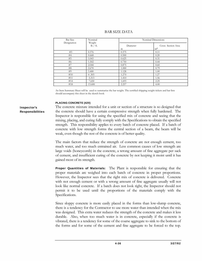
3/27/02 4-36
BAR SIZE DATA
Bar Size Designation
Nominal Weight lb / ft.
Nominal Dimensions Diameter Cross Section Area in in²
#3 0.376 0.375 0.11 #4 0.668 0.500 0.20 #5 1.043 0.625 0.31 #6 1.502 0.750 0.44 #7 2.044 0.875 0.60 #8 2.670 1.000 0.79 #9 3.400 1.128 1.00 #10 4 .303 1.270 1.27 #11 5.313 1.410 1.56 #14 7.650 1.693 2.25 #18 13.600 2.257 4.00 An Item Summary Sheet will be used to summarize the bar weight. The certified shipping weight tickets and bar lists should accompany this sheet in the sketch book PLACING CONCRETE (420) The concrete mixture intended for a unit or section of a structure is so designed that the concrete should have a certain compressive strength when fully hardened. The Inspector is responsible for using the specified mix of concrete and seeing that the mixing, placing, and curing fully comply with the Specifications to obtain the specified strength. This responsibility applies to every batch of concrete placed. If a batch of concrete with low strength forms the central section of a beam, the beam will be weak, even though the rest of the concrete is of better quality.
The main factors that reduce the strength of concrete are not enough cement, too much water, and too much entrained air. Less common causes of low strength are large voids (honeycomb) in the concrete, a wrong amount of fine aggregate per sack of cement, and insufficient curing of the concrete by not keeping it moist until it has gained most of its strength.
Proper Quantities of Materials: The Plant is responsible for ensuring that the proper materials are weighed into each batch of concrete in proper proportions. However, the Inspector sees that the right mix of concrete is delivered. Concrete with not enough cement or with a wrong amount of fine aggregate usually will not look like normal concrete. If a batch does not look right, the Inspector should not permit it to be used until the proportions of the materials comply with the Specifications.
Since sloppy concrete is more easily placed in the forms than low-slump concrete, there is a tendency for the Contractor to use more water than intended when the mix was designed. This extra water reduces the strength of the concrete and makes it less durable. Also, when too much water is in concrete, especially if the concrete is vibrated, there is a tendency for some of the coarse aggregate to sink to the bottom of the forms and for some of the cement and fine aggregate to be forced to the top.
Inspector’s Responsibilities
3/27/02 4-37
The cement-sand mortar shrinks more than concrete with enough coarse aggregate, and the uneven shrinkage sets up stresses in the beam that can cause cracking. The total amount of water in a concrete mixture, consisting of the moisture in the aggregates and the water added to the other materials, must not make the water-cement ratio too great and must not cause the slump to be greater than the specified value. Cracks in the top of a beam indicate that the concrete contained too much water and the slump was greater than that specified. For these reasons, slump tests must be made often, and the right way and with the right equipment.
The right procedure for making a slump test is described in the latest revised edition of “Instructions for Sampling and Testing of Fresh Mixed Concrete,” published by OMT. For the control of a project, slump tests must be made at the required frequency in accordance with the instructions in the latest revised edition of “Guide for Control Sampling and Testing,” by OMT. “Frequency of Sampling and Number of Test Specimens” in the first-mentioned references gives additional guidance. An Inspector must not permit the use of concrete whose slump is too great. Low-slump concrete will not flow easily down a chute and will not flow into place in the forms, but can be placed and compacted with the proper handling equipment. It is the Contractor’s responsibility to provide and use suitable equipment.
Entrained Air: Although a small amount of entrained air makes placing and finishing concrete easier and greatly increases its durability, it also decreases the strength. A large amount reduces the strength seriously. Even when an air-entraining agent or an air-entraining cement is used in proper proportions, the percentage of entrained air in the concrete may vary over a wide range, because the air content of the concrete in the forms depends on many factors, including time, temperature, and amount of fine aggregate. For these reasons, it should never be taken for granted that the air content is correct; the air content must be tested frequently. The Inspector should determine the required frequency by referring to the publications of the OMT mentioned previously. To control the mix, air content must be tested at the required frequency. However, it should be tested whenever the concrete does not look normal or whenever the finishing operation seems to be easier or harder. If the air content is above or below the percentage specified after a second test, corrective action must be taken at once.
Making Field Tests: The Inspector is responsible for controlling the air content and the amount of water added to any concrete mixed at the job site by making enough tests. The Inspector is also responsible for having the proper equipment for sampling and testing the concrete. The required equipment includes a slump cone and a tamping rod for making slump tests and an air meter. The Inspector will make all test cylinders used for acceptance and the Contractor’s personnel shall make early break test cylinders, however, the Inspector monitors the preparation, curing, and transportation of all the cylinders. The list of apparatus in “Instructions of Sampling and Testing of Fresh Mixed Concrete” by OMT should also be consulted. If the needed equipment is not available, the Inspector must notify the regional lab
3/27/02 4-38
immediately. The Inspector must make all the required tests and keep complete written records in the project record book to document the tests.
All tests should be made on samples that are truly representative. Concrete is a mixture of coarse aggregate, fine aggregate, cement, air, and water. The sizes of the solid particles range from very small to 1 in. to 2 in. diameter, and a very solid particle is much heavier than water. When the concrete is discharged from a mixer or a truck, flows down a chute, or is dumped into forms, the small solid particles tend to separate from the large particles, and all solid particles tend to sink to the bottom. As a result, more liquid material is left at the surface. The proper way of taking a sample of concrete from a batch is to collect the sample in such a way that it will have the same proportions of coarse aggregate, fine aggregate, cement water, and entrained air as does the entire batch. After the Inspector has collected a sample, he/she must be careful to prevent water loss from it.
A general tendency is for the ingredients of concrete to segregate in such a way that the first portion of concrete discharged from any type of mixer has a higher proportion of cement than does the portion discharged last. If concrete is allowed to flow from the unbaffled end of a chute, there is usually more cement in the concrete nearest the chute. Unless these and other types of segregation are overcome in taking a sample, a truly representative sample will not be obtained and the results of tests may not give the correct information.
Approving of Materials: Whether at a plant or on the job site, the Inspector is responsible for making sure that all materials have been approved. This approval must be in writing and must cover both the source and its acceptability, and no materials are to be used in the work until approval has been obtained. The job Inspector must have copies of the approved concrete mix design and approved test reports for the fine and coarse aggregates, cement, and any admixture that is to be used. All other materials (such as joint material, membrane curing compound, and reinforcement) used to build a structure must also be approved by OMT.
The Certified Plant Technician also must see to it that all necessary equipment is in good working order.
Delivery Tickets and Records: The Inspector must keep written records of all tests to document the inspection work. Tickets must be numbered serially, and there must be two or more copies of each ticket. This responsibility applies to all structural concrete, regardless of whether the materials are mixed at a central plant, in stationary mixer or truck-mixer. The Plant is responsible for, and must verify, the data shown on these tickets. Each ticket must show the mix of concrete.
Required Preparations Before Ordering Concrete: The Inspector must make sure that no concrete operations are started until everything is in acceptable condition and ready for concreting. The term “everything” includes foundations, forms, reinforcement, equipment, labor, and curing materials. The Inspector must have
3/27/02 4-39
copies of approvals for reinforcement, form release compound, curing materials, and any other items needed for that portion of the work.
The Inspector must make it clear to the Contractor that the Contractor is responsible for ordering the concrete but must check with the Inspector before doing so.
PLACING CONCRETE CHECKLIST (420) See that
1. Pre-placement Conference is conducted.
2. All necessary testing equipment is on hand, such as the slump cone and tamping rod, the cylinder molds, the air meter and check cylinder, and a maximum-minimum thermometer for cold weather.
3. The concrete mix design is approved.
4. Contract plans are checked for the quantity of concrete to be placed, and for details of any construction joints.
5. Working drawings are checked for the rate of placing concrete.
6. Foundations, forms, reinforcement, and all other items are in an acceptable condition and ready for concrete operations; approvals are obtained for all materials to be incorporated in the construction.
7. The following items are checked with the Contractor: a. Concrete mix design and mix number. b. Amount of concrete to be placed. c. Schedule of placing concrete. d. Personnel and equipment used.
See that
1. The concrete complies with the concrete mix design, and the amount of water added does not cause the water-cement ratio to exceed that specified by the mix design.
2. The slump and air content of concrete are checked with the required frequency.
3. Concrete is placed as required by the Specifications, and the necessary hoppers, chutes, elephant trunks, runways, buggies, and other such equipment are being properly used.
4. Careful attention is given to the placing of concrete around reinforcement.
Before Placement
During Placement
3/27/02 4-40
5. A constant check is maintained on the alignment and grade of the forms.
6. The concrete is properly spaded and vibrated.
7. Excess water and laitance are removed.
8. Finishing is as specified.
9. The required number of test cylinders are made and are protected at the proper temperature.
10. The Contractor is providing for protection and curing of the concrete to fully comply with the Specifications.
See that
1. The concrete is protected and cured in accordance with the Specifications.
2. Forms are not stripped until the specified time has elapsed.
3. Cylinders for determining the early strength are cured under the same conditions as the concrete just placed.
4. The cylinders made to check the design of the mix are stored under the specified conditions.
Careful attention must be given to the method of moving mixed concrete to the point where it is placed in the forms. If a perfectly mixed batch of concrete becomes segregated while being conveyed from the mixer to the forms so that the coarse aggregate separates from the rest of the mixture, the concrete will be inferior. The Inspector must never permit concrete to be placed in one end of a form and be forced to flow along its length. In general, the equipment used for placing concrete should deposit it in the position it will occupy as part of the structure. A short chute, not over 15 ft. in length, may be used to lead concrete from the carrying device into the forms, provided that the chute is properly made and handled and does not segregate the concrete.
A longer chute can be permitted only if its use is authorized by the Project Engineer. The Specifications give the requirements for constructing and arranging chutes. A chute must be kept free of accumulations of hardened concrete by flushing with clean water after each use. The flushing water must be discharged outside the forms. If the concrete that comes from the mixer will not slide down the chute, it must be pushed down the chute with shovels. Extra water should never be added to mixed concrete to make it flow down the chute.
After Placement
3/27/02 4-41
Concrete must never be chuted or dumped into forms so that it will hit the exposed parts of reinforcement bars with great speed. If rapidly moving concrete hits the bars, it will always segregate. Concrete must be placed around all reinforcement so that it will encase the steel without moving the reinforcement out of position, and so that there will be no honeycombs or large voids in the concrete.
Unless otherwise specified in the Contract Documents concrete must never be dropped through the air more than 5 ft. If it drops farther, the coarse aggregate will separate out. As a result, there will be too much mortar in some places in the forms and too much coarse aggregate in others. When concrete is being placed in the lower part of a deep form, some type of sheet metal or canvas tube, called an elephant trunk, should be used to lead the new concrete down to the concrete surface already in the forms. Also, the air temperature must be noted and care exercised to make sure that the specified pouring rate or the specified maximum vertical rise of the concrete is not exceeded. If the rise is too rapid, the excessive pressure against vertical form surfaces may damage or even rupture the forms.
Consolidating Concrete in Forms: All fresh concrete must be internally vibrated and spaded so that air and free water can come to the surface. In some heavily reinforced sections where the steel bars are so close together that internal vibration is impractical, external vibration may be necessary. A spade is used to push the coarse aggregate away from the surface of the form. The spade should be slid down close to the form and then tipped away from it. Spading the concrete along the form helps to get rid of air bubbles that would show up later as shallow holes on the surface of the structure. When properly done, spading gives a smooth, dense, and pleasant appearing surface that requires very little final finishing.
Concrete should not be overworked during the spading operation. If the right amount of mixing water is used and the concrete is mixed, placed, and spaded properly, very little free water will come to the surface. If too much free water shows up on the surface of the concrete, or bleeding occurs, this water must be removed from the forms and steps must be taken to prevent further bleeding. To get good results, the quantity of mixing water may be reduced or the gradation of the aggregates may be improved. If free water remains on top of the concrete, a scum of thick, soupy mortar called laitance will collect on the upper surface. This laitance is very weak if allowed to harden. To prevent laitance, the forms should be overfilled and the extra material struck off after the water has risen to the top. This rising usually takes about an hour.
When plywood forms are used, or when liners of pressed wood or metal are used with ordinary lumber, the forms are often so tight that it is difficult to get the air bubbles out of the concrete by spading. After the forms are stripped, very small holes, sometimes called “bugholes,” may be in the concrete surface. When very tight forms are used, extra care must be taken to prevent such holes. The concrete should be placed in shallow lifts and vibrated thoroughly to release the air, and then the air
3/27/02 4-42
should be allowed to escape by sliding a spade down along the form surface and forcing its top away from the form.
Vibration: The Specifications require that, with few exceptions, all the concrete in a structure be consolidated by vibrators. An internal vibrator, which has a spud at the end of a flexible shaft, should be used wherever possible. When the spud of a vibrator is placed in the concrete, it liquefies the concrete more so entrapped air and water can rise to the top. If the spud is left in one place too long, however, the coarse aggregate will sink through the mortar to the bottom of the layer, segregating the concrete. When the segregated concrete hardens, the part of the layer with the most mortar in it will shrink more than the rest, and the concrete will crack. Cracks across the top of a beam, often located directly over the stirrups, is usually a sign that the concrete has been vibrated too much or is too wet, or both. The spud of the vibrator should never be left in one place for more than 5 seconds. As soon as air bubbles stop rising and the surface of the concrete around the spud or flexible shaft starts to look shiny, the spud should be pulled out, moved to a new position about 2 ft. away, and dropped into the concrete there.
Using a vibrator that meets the requirements of the Specifications should change the appearance of the concrete surface with a 1 in. slump for about 18 in. around the spot where the spud is placed in the concrete. If it does not, the vibrator is not getting all the air and extra water out of the concrete. When the concrete is vibrated properly, it is liquid enough to run into all corners of the forms. As a result, the concrete will have a smooth surface when the forms are stripped.
When concrete is vibrated, greater pressure is exerted on the forms, so the form material must be thicker and stiffer than if the concrete were spaded without a vibrator. When a thin wall section is filled with stiff concrete and the concrete is vibrated powerfully, the pressure on the forms may be great enough to spread the forms apart, because the tightening wedges at the ends of the form ties may be forced into the wood of the walers. As a result, the wall will be thicker and the volume of concrete greater than intended. In the case of a high wall, the rate of placing the concrete, measured in terms of the rise of the concrete in units per hour, should be controlled to prevent damage to the forms.
The vibrator spud should not be placed against the reinforcement, because movement of a bar will spoil the bond where the concrete around the bar has partly hardened. The vibrator spud should be used to work the concrete around the steel. Another important precaution is to not lower the spud into a previously vibrated layer below the one currently being placed and vibrated.
Concreting Parapet: Concrete in parapet walls and median barriers can be constructed by either the slip form method or conventional fixed form method. The slip form method shall be constructed in conformance with Section 420.03.04(e).
3/27/02 4-43
If the forms for a parapet are built well and if the concrete is properly placed, vibrated, and spaded, the concrete surfaces should require little finishing when the forms are removed. When the forms for a parapet have been filled nearly to the top, all water and laitance should be removed, and the form should then be overfilled with fresh concrete. After the concrete has shrunk, the top surface should be screeded off slightly above the desired final grade. It should be given its final finish as soon as the concrete attains the proper set.
COLD WEATHER CONCRETE OPERATIONS (420) When concrete is placed in cold weather, the Contractor must take proper precautions while the concrete is being mixed, placed, and cured so the completed structure will meet the Specifications requirements.
The speed of the chemical reaction that causes concrete to harden depends on the temperature of the mixture at the time of placing. If the temperature of the concrete is above 50F when it is placed in the forms, the chemical action will start rapidly and will produce enough additional heat to permit the concrete to harden and gain strength rapidly. When the temperature is less than 50F, the chemical action is slower and produces less heat and the concrete will gain strength more slowly. If the temperature is too low, the water in the concrete may freeze before the chemical action is completed. On the other hand, if the temperature of the concrete is too high when it is placed, the concrete will have less slump than usual with the same amount of mixing water, and placing will be more difficult. Also, the concrete may take a “flash set,” or may start to harden, before it is in its final position in the forms. Concrete placed at a temperature higher than about 80F may have a lower ultimate strength than concrete placed at a lower temperature, and it will have a greater tendency to crack.
During cold weather, a mixing temperature of about 70F is usually best. Under ordinary conditions, heat losses during transportation and handling will not reduce the temperature of the concrete below 50F when it is placed in the forms.
Calculating Temperature of Mixture: Perhaps the easiest way to warm up a batch of concrete is to heat the mixing water. However, this method is adequate only in mild weather and when the aggregates are not too cold. Only a relatively small amount of heat can be added to the water for two reasons: (1) the water forms only a small part of the total batch; and (2) if the water is heated to about 165F or 170F, it may cause a “flash set” when the water contacts the cement. Therefore, in severely cold weather it is nearly always necessary to heat part or all of the aggregates as well as the water.
Precautions in Heating Aggregates: When aggregates are heated, the heat must be applied without a flame or moisture directly contacting the aggregates. Aggregates are usually heated by steam or hot water circulating in pipes. The Contractor should
3/27/02 4-44
never use a flame thrower or direct flame, or apply live steam or hot water directly on the aggregates.
Whenever the sand or coarse aggregate for a batch of concrete has been heated to a high temperature, it is best to allow some time for the heat to be distributed through the cement and all the aggregate before the water is added to the batch. When a truck mixer is used, the drum should be revolved a few times after the solids have been put in and before the mixing water is introduced.
FINISHING CONCRETE (420) The surface of each portion of any concrete structure must be finished in the manner required by the Plans, IFB, or Specifications. Finishing a concrete surface must be done by a competent person and by the specified method. Concrete with a defective surface finish is not acceptable. The Inspector should never accept a finish obtained by plastering over the concrete a thin coating of cement mortar that will soon scale off.
CURING CONCRETE (420) After the concrete has been placed and finished, it must be cured. Curing involves keeping it warm and moist until it has gained most of its strength. The curing of concrete also has a great effect on its durability. While concrete is setting, the solid particles are separated by many very small holes and channels, which are filled with the mixing water. If the concrete is kept moist, the water acts on the cement to form a gel which partly fills the holes and channels and binds the pieces of aggregate in the hardened concrete. Once the concrete has dried out, gel formation stops. The longer the concrete is cured, the greater the amount of gel and the better the concrete. It will be stronger than if it had been allowed to dry out too soon after being placed.
Any delay in starting curing, especially in hot or windy weather, can cause surface cracking of the concrete. Curing is most important during the first few hours after the concrete has been finished, but it must be continued as long as the Specifications require. Curing must be started as soon as the concrete has set sufficiently to apply the curing material. During cold weather, curing is required while the concrete is protected against the cold, using the specified method. The Inspector must check the work frequently to make sure that the curing is continuous and that the concrete surface does not become dry during the curing period.
Records: The payment for concrete is usually based on either volume or a lump sum price. The record in the Inspector’s daily report and on the daily construction log should include the mix number, quantity, and exact location in the structure of all concrete placed and also the equipment and personnel used. The weather conditions, such as the temperature and rain or wind, and other conditions, such as a delay in the supply of concrete, a breakdown of equipment, a break in the forms, or any other event interrupting the placement of concrete, should also be noted. Records should be kept on the number of slump and air tests and the number of the test cylinders made, and materials Form No. 4 should be filled out.
3/27/02 4-45
Records to keep in the project record book include, but are not limited to, the results of tests for slump, air content, and compressive strength; the temperature of heated concrete when it is placed; and the temperatures maintained during curing. The Inspector should also include the dates on which structure forms were stripped and the dates on which curing or heating was discontinued. The records must show the checks that were made on the number, size, and positions of reinforcement in structures. Also, where test results have indicated any inadequacies, records should document the results after corrective measures were taken.
CONCRETE BOX CULVERTS CHECKLIST (420) See that
1. The foundation material is of suitable quality or is removed and replaced with selected backfill.
2. The flow line is checked for proper elevation.
See that
1. Year-built numerals, if required, are properly installed.
2. The top slab is finished properly.
3. Curing is started immediately.
4. Protection against freezing is provided in cold weather.
See that
1. Forms are left in place for the specified period.
2. Concrete has attained adequate strength before backfill is placed and compacted.
Construction: Arrangements should be made in advance to dewater the excavation for a concrete box culvert and to prevent flooding for at least 12 hours after the concrete for the base slab is placed. The base slab should be constructed to its full thickness in one layer. The top slab of a small culvert may be placed without a construction joint on the sidewalls. All water and laitance must be removed from the concrete in the sidewall forms before the concrete for the top slab is placed.
If the top slab surface of a box culvert will be exposed to traffic, great care must be taken in the finishing process so that the riding quality of the slab will be equal to that of the rest of the pavement.
Before Construction
During Construction
After Construction
3/27/02 4-46
Tests for slump and air content must be made on the concrete, and test cylinders must be made. Proper procedures are described in “Instructions for Sampling and Testing of Fresh Mixed Concrete,” an OMT publication.
Curing and Protection: The concrete in a box culvert must be given the full amount of curing required by the Specifications. Cotton mats or burlap used for curing must be kept wet for the specified period. A box culvert often has a fairly thin concrete section that can freeze easily in cold weather; therefore, particular care must be taken to prevent freezing during the curing period.
Records: Payment for concrete in a box culvert is based on a lump sum price. If soil must be removed below the planned elevation of the bottom of the base, the records should include the volume of extra excavation and the volume of selected backfill replacing unsuitable material. Other required records are noted earlier under “Concrete Structures.”
SUBSTRUCTURE CHECKLIST (420) See that
1. Elevations of beam seats are checked.
2. Locations of inserts are checked.
3. Span lengths are double-checked.
4. All preparations are complete.
See that
1. The concrete is of uniform consistency, and is placed and screeded properly.
2. The distance to the reinforcement from the surface of the concrete is checked often.
3. The approved sequence and method of placing concrete is followed.
4. The method of curing is applied promptly and continuously for the specified time.
See that
1. Forms are first loosened and then removed gradually to avoid sudden chilling of hot concrete.
The substructure of a bridge, as generally classified in a Contract of the Administration is that part of the bridge above the footings and below the truss, floor beams, or deck slab. However, it includes the safety curbs and parapets on the
Before Construction
During Construction
After Construction
3/27/02 4-47
abutments. The substructure therefore includes the columns, pier shafts, bents, caps, abutments, beam seats, wing walls, back walls, and other parts of the bridge shown on the Plans constructed before the superstructure or deck. Constructing the substructure of a bridge usually requires a large volume of concrete. Moreover, special precautions must be taken in placing this concrete. Nothing is so sure to result in a poor job of concrete work as failing to prepare completely before starting concrete work. Every operation must be planned in detail, particularly unusual operations.
Preparations for Placing Concrete: Before any concrete is mixed or ordered for a substructure, the Inspector must make sure that the Contractor has everything ready. Equipment must be on hand for placing concrete in every part of the substructure. The Contractor must plan ahead the concrete placement so that concrete will be placed first in the corners of the forms and the surface of the fresh concrete will be kept nearly level to the form tops at all times. Tools for spading the concrete must have handles long enough to reach all parts of the forms, and the Inspector must check that the vibrators are in good condition. An extra vibrator must be on hand in case one breaks down. Materials and equipment for curing the concrete, and for protecting or heating it in cold weather, must be ready before placing the concrete.
Plans and preparations should be made and equipment checked in case work stops because of rain, a delay in mixing or concrete delivery, or movement of the forms. Places where a construction joint will be used should be located in advance, and material for bulkheads and keyways should be on hand. If concrete placing of a wall must be stopped before the forms are filled, straight wood strips, cut in advance, should be nailed to the inside of the form to bring the top edge of the concrete to a neat line.
There must be enough workers on the job to place and finish the concrete without stopping until completing a section of the structure. When concrete has set, fresh concrete may not bond to the old surface. A 30-minute break can cause a “cold” joint. Such a joint will show as a crack on the surface after the forms are stripped, and water may leak through it. Trouble can be prevented by properly installing a construction joint when work is stopped for some time.
Inspecting Forms and Reinforcement: Instructions previously given for inspecting forms and reinforcement also apply to a substructure. The Inspector should make sure that tubes or inserts for any required weep holes or other drainage openings have been installed. Material for water stops must be available.
Requirements for Bonding to Previous Pours: When concrete is to be placed on another layer, the Inspector should make sure that the surface of the existing layer is at least 12 hours old so that most of the early shrinkage will have taken place. Any concrete surface on which fresh concrete is to be placed must be properly prepared. The old surface must be free from hardened laitance, and no weak mortar must be on
3/27/02 4-48
the surface. Any such material must be removed. A jet of water from a high-pressure nozzle is best for this work. The concrete surface must be saturated with water before any concrete is placed, but any pools must be removed.
Precautions in Placing Mass Concrete: The instructions previously given for inspecting concrete placement must be remembered during the construction of bridge substructure. Also, special care must be taken to prevent the concrete in the forms from becoming too hot.
When concrete is placed in a large mass, the concrete temperature increases quite rapidly as it hardens. If the concrete temperature in the forms is allowed to get too high, the concrete may be cracked or otherwise damaged. The temperature of concrete placed in a large mass can not exceed 80F .
Checking Dimensions: During placing of the concrete in a substructure, the Inspector must maintain a constant check on the grade and alignment of the forms. The elevations of the beam seats must be accurately checked against the elevations shown on the Plans. The Inspector must check and recheck the length of the span and the positions of anchor bolts making sure that all required inserts are installed and that each is firmly fastened in the proper position. Such a small fixture can be easily knocked out of place.
The Inspector also must make sure that the concrete is properly finished, that any necessary keyways are installed, and that the concrete is continuously cured.
Records: The Inspector should refer to the instructions given previously for keeping records under “Concrete Structures.”
CONCRETE BRIDGE DECK CHECKLIST (420) See that
1. The profile grade of the bridge deck is established and the deflections of beams at control points are computed.
2. The elevations and slopes of the end dams are computed.
3. Elevation readings are taken at the predetermined control points.
4. Pre-deck conference is held.
5. Telltales are provided, where possible, for checking deck deflections.
6. Any necessary adjustment in the profile grade is made.
Before Construction
3/27/02 4-49
7. Actual distances above beams for end dams, deck forms, and screed rails are computed, and these items have been set to the computed distances by measurements from the tops of the beams.
8. The finishing machine and all transverse construction joints are set parallel to the abutment and pier support lines on all bridge deck slabs.
9. All preparations for placing concrete are checked.
10. The position of the reinforcement is checked.
See that
1. The concrete is of uniform consistency, and is placed and screeded properly.
2. The distance to the reinforcement from the surface of the concrete is checked often.
3. The approved sequence and method of placing concrete is followed.
4. The surface is tested with a straightedge, and corrections are made to ensure a smooth riding surface.
5. The method of curing is applied promptly and continuously for the specified time.
See that
1. All portions of the bridge deck comply with the straightedge tolerance, and all points that were too high are corrected by grinding.
2. All expansion joints are checked for freedom of movement.
Special attention must be given to every detail of construction of a concrete bridge deck, since the traveling public judges a highway bridge by its appearance and by the riding qualities of the deck. A smooth-riding deck must have a grade line without waves or dips and must have a true cross section. Certain special problems must be considered. The mass of the concrete causes the beams and girders supporting the deck slab to bend or deflect, and the amount of this deflection changes as the concrete is being placed. Placing concrete in the forms for a bridge deck causes all parts of the deck and all supporting beams to deflect. After the concrete for the slab has been placed, the sag in a supporting beam with an 80 ft. span may be as much as 2 in. so that the deck will have the right profile after the bridge is completed, the screed guides or rails to which the concrete surface is finished must be set to a suitable curve. The profile of the finished deck depends on the accurate setting of the
During Construction
After Construction
3/27/02 4-50
screed rails, which must be at the proper elevations. If they are not set properly, the deck will not be smooth riding, even though it passes the test with a straightedge.
The designer has no way of knowing how far the surface of the concrete deck should be above the tops of the beams at all points, since the beams may not be straight. The allowable departure from straightness when a steel beam is rolled may be as much as 3/4 inch up or down. Also, the bridge designer does not know exactly what elevation the concrete surface should have when the concrete is placed, since this elevation will depend on the weight of the deck forms built by the Contractor. Moreover, the correct profile may not be obtained by placing concrete to a certain theoretical elevation, since deflections caused by future placement of concrete will change the elevations of all parts of the deck already placed.
The finished grade of a bridge deck must be controlled by finishing the deck slab surface of specified thickness so that it will be at a given distance above the structural steel.
Using the Deflection Diagram: The Bridge Plans include a diagram for each steel beam showing how that beam will deflect under the mass of the concrete throughout the entire bridge deck. Such a diagram gives the net vertical movement at any point of the steel beam before any concrete is placed in the deck to its position when it is loaded with the entire deck. The same diagram may be used for two or more beams, or even for all beams, if the deflections are the same or very nearly equal. Bridge Design also has computer sheets on deflections which should be used.
To determine the proper elevations of the screed guides use Form OOC 30. The first step is to measure the elevations of the tops of the steel beams immediately after the splices have been bolted, riveted, or welded into position and before the load of the forms is placed on the beams. Then, with the aid of the diagrams showing the deflections of the beams due to the mass of the concrete only, it is possible to compute the final elevations of the beams after the concrete is placed and the forms are removed. When the Inspector knows the final elevation at a point on a beam after all concrete is in place and also the final required elevation of the finished deck slab at that point, he/she can easily compute the vertical distance from the top of the beam to the concrete surface to give the desired finished grade elevation.
Establishing Profile Grade: The first step in obtaining all the grades needed later is to establish a profile grade line along the span of the bridge. This profile grade line may be either a single straight line or a vertical curve. Elevations along the profile grade line should be computed for stations at predetermined intervals one-eighth of the span length.
Computing Deflections at Control Points: From the deflections diagram given on the bridge Plans the Inspector should determine the deflections at the centerline of each span resulting from the mass of the deck, excluding the weight of the beams and girders themselves. This deflection is usually given in inches. From this deflection at
3/27/02 4-51
the centerline of the span, the Inspector should determine the corresponding deflections, caused by the deck weight, at the other points that will be used as control points.
Computing Theoretical Positions of Screed Strips and End Dams: The amount of the deflection at each control point caused by the deck weight should be added to the elevation computed for that control point on the profile grade line. The results will be a series of elevations defining the shape of the adjusted profile to which the deck forms and screed strips are to be set.
By making the proper computations and corrections for crown, these profiles can be used in relation to the top of any beam at control points for screed strips and deck forms, at any distances laterally across the deck from the beam. With a skewed bridge, a separate set of curves has to be plotted for each beam, because the centerlines of the bearings for different beams are at different stations along the profile.
From the control dimensions on the contract Plans for the bridge deck, the Inspector can compute the theoretical distance from the adjusted profile grade line (as corrected for deflection) to the top of any beam at any control point.
The elevations of points on the end dam over each beam can also be computed. Also, the slope of an end dam in the direction of the span can be determined. If the profile grade line is a vertical curve, then the slope of the tangent to the curve can be computed at the station of each end dam, and the top surface of the dam should be set to this slope.
All the computations just described can be performed at any time before erecting a beam. Therefore, all the necessary information should be available before delivering or erecting any portions of the deck structure.
Computing Actual Measurements: After the beams and diaphragms are erected and connected, profile levels must be run along the tops of all beams. Elevation readings should be taken at the predetermined control points, each of which should previously have been marked with a center punch within a painted circle. It may be found that the beams are straight, cambered, overcambered, or even sagged in some cases. Each beam must be checked and treated separately. Averages cannot be used.
From the profiles of the adjusted grade line and the beam top, plotted to an exaggerated vertical scale, elevations can be computed or scaled to establish the heights of the tops of the end dams and screed strips above the top of the beam. In the same way, heights from the top of a beam to the surface of the deck forms at haunches can be determined at control points.
Setting Heights of Forms and End Dams: To set the forms and end dams at the proper heights above the top of a beam at control points on the beam, the Inspector
3/27/02 4-52
should use a rule or a carpenter’s try square to measure up from the beam, instead of determining elevations with a level and a leveling rod. In other words, all final measurements for heights of end dams, screed strips, and forms for deck haunches should be referenced to the tops of beams in place, rather than to a fixed survey datum.
After an end dam has been set to the proper height, the longitudinal gradient across its top surface should be checked and adjusted, if necessary, to make it parallel to the profile grade line at that station. The Inspector should prepare a board about 24 in. long by dressing one edge on a taper so that this edge will be parallel to the desired gradient when the other edge is held level. Then, when the dressed edge of this slope board is placed across the top of the end dam and held parallel to the longitudinal centerline of the span, a carpenter’s level on the top edge of the board will indicate when the top of the end dam is sloped parallel to the profile grade line.
After measuring and adjusting, the Inspector should always make a final check by sighting along in the tops of the deck forms and screed rails, or by using a stringline, to make sure that the deck surface will be free from obvious irregularities and that traffic will ride smoothly over it.
STAY-IN PLACE (SIP) FORMS (420) Permanent steel forms are used to form concrete deck slabs on bridges with steel stringers and must conform to the Maryland Standard Specifications requirements, Sections 909.11 and 420.03.02(g). The forms are to be fabricated and installed according to the Office of Bridge Development Standard (OBD) #BR-SS (6.06)-75-29. Special note shall be taken to ensure that all welding is performed by a Administration certified welder and that no welding to the portion of the stringer, which is in tension, will be permitted at any time. Working drawings will be prepared by the Contractor and approved by OBD before fabrication and installation of SIP forms. Forms shall be installed to proper line and grade as described elsewhere in this chapter.
Setting Screed Rails: Screed guides or screed rails are set at a uniform distance above the finished deck grade. They should be located over beams and held in place by fixed supports that are close enough together to permit the rails to carry the heavy finishing machine without bending. The rails must not be supported on the deck forms. The supports should be spaced about 5ft. apart, and must be adjustable for height as determined by measurements for the top of the steel beam. Supports on one side of the roadway should be opposite the centers of the spaces on the other side. The supports should be of the type that can be removed easily after screeding is completed. Form Plans will show support spacing.
Preparing To Place Concrete: Before the construction of a bridge deck, the Inspector should discuss with the Contractor the general plan of operation and the following details: the type of screed rails and their supports; the type of finishing equipment; the number and types of mixers and pieces of equipment for transporting
3/27/02 4-53
the concrete; the procedures for placing, finishing, and curing the concrete; and the number of finishers and their experience and skill. The Inspector should check the tools available, such as portable work bridges, screeds, vibrators, scraping straightedges, testing straightedges, and lutes. The specified curing materials must be on hand. Also, the Contractor should have available extra burlap to protect the concrete in case of rain, and have adequate lights for night work. Each item of equipment the Contractor intends to use must be on the job and inspected before the job starts. Any item that is defective or in poor condition must be replaced. To control deflection and keep it uniform, the concrete in a bridge deck is placed in sections in a prearranged sequence, as noted on the Plans.
Checking Position of Reinforcement: After the reinforcement steel and screed rails are in place, the position of the steel must be checked by a dry run with the screed machine. If the steel is high or low at any spot, it should be immediately adjusted and secured in the proper position. Each end dam should be checked and, if necessary, jacked up and held in the proper position by shims. If the concrete is to be placed in the deck in sections, the bulkheads must be in place and checked for fit and dimensions.
The screeding surfaces of each piece of equipment should be checked for proper cross sections and straightness. The screeds on a finishing machine that rides on rails above the pavement surface should be checked in the down position to make sure that they are adjusted to the right profile grade and cross section.
Placing and Screeding Concrete: The concrete delivered to the deck slab must be uniform in composition, workability, and consistency and the slump should be between 2 in. and 5 in. A batch or load that is too wet or too dry should not be placed, since it may cause unevenness in a portion of the surface after being struck off. Concrete must be placed in the forms without segregation and as close as possible to its final position. It should be deposited in the forms to uniform thickness from a crane bucket, conveyor, or pump, and spread by workers with shovels so it leaves a small amount for finishing screed to strike off the surface. Vibrators should be used to compact the concrete around the reinforcing steel and in the corners of the forms.
A finishing machine should move at a slow, steady speed. The screed should always be carrying a uniform amount of concrete across its full width. It should not be used to bulldoze the concrete. The distance from the concrete surface to the top of the reinforcement steel should be checked frequently. This check can be made by working a thin metal plate about 12 in. long and 6 in. wide into the concrete until it hits the steel. A line may be scribed on the side of the plate to show the proper depth of concrete. The position of the steel is a critical item in construction, since disintegration of the deck surface will occur because of insufficient concrete cover. The Plans for a bridge deck may show a pattern for placing concrete that requires construction joints. This pattern must be followed, since less stress will be placed on
3/27/02 4-54
the concrete already placed and hardened when the beams are deflected by the weight of the new concrete. Because of the deflection of the beams, the first batch of concrete placed in a portion of the slab between construction joints must be still plastic when the last batch in that portion is placed. If concrete moves after it has set and while it is still weak, cracks will be built into the deck.
Finishing Concrete: Finishing operations on a bridge deck should be done as quickly as possible without overworking the surface. After the surface has been finished, it should be tested with a checking straightedge. Low spots must be filled with fresh concrete.
Records: The Inspector should record the deflection computations and elevation readings for control points on beams, any adjustments in the deck profile, and all measurements from the tops of beams for forms and end dams. The Inspector should also record work progress on the I.D.R., and the temperature and weather conditions and any construction difficulties or deficiencies. The records should also show the following items: the extent and method of use admixtures; the results of tests for slump and air content; and the numbers of test cylinders. All concrete tickets should be filed.
PRESTRESSED CONCRETE CHECKLIST (440) See that
1. All beam seats are checked for proper elevation and condition.
2. Suitable arrangements are made for transportation, handling, and storing beams.
3. All inspection reports or stamps are in order.
4. Pre-erection meeting is conducted.
See that
1. The required pads are in place at the bearing points on piers or abutments.
2. Beams are lifted by the proper lifting points or inserts, and the erection diagram is followed.
3. Anchor bolts are installed at both the fixed ends and free ends of the beams, and proper provision for expansion is made at the free end.
See that
1. The spaces around anchor bolts at the fixed ends are filled with grout.
2. All surfaces are cleaned and excess or spattered mortar is removed.
Before Erection
During Erection
After Erection
3/27/02 4-55
A prestressed concrete beam is a reinforced concrete member in which the steel reinforcement and the concrete are stressed while the member is being constructed and before loads are applied to it. Such a member is designed to act as a simple beam, or one that is supported only at its ends. The prestressing force is applied by jacks or other devices to stretch the steel wires, cables, or bars that are embedded in the concrete. Both the steel and the concrete must have high strength. After the concrete has hardened, the stretching force is released, and the tension in the steel produces compression in the concrete.
The objective in prestressing in reinforced concrete is to use high-strength steel and high-strength concrete to better advantage. In the case of a beam, the result is a much lighter member that may have a longer span than one built with ordinary reinforced concrete, because of the reduced dead mass. When a prestressed concrete beam and an ordinary reinforced concrete beam, having the same span, are designed to carry the same load, the prestressed concrete beam may require only 75 percent as much concrete and only 50 percent as much reinforcement steel. Even though a prestressed concrete beam is less bulky than an ordinary reinforced concrete beam, it is stiffer and deflects less. However, a prestressed concrete member must be made of very high quality concrete, and a special type of steel must be used for the reinforcement. Also, special equipment is needed, and great care must be taken in constructing and handling the member.
When a load is applied to a beam that is supported only at its ends, the material in the upper part of the beam is squeezed together and subjected to compressive stress, while the material in the lower part of the beam is pulled apart and subjected to tensile stress. Concrete has high compressive strength but is weak in tension. In a reinforced concrete beam, reinforcement steel is placed in the bottom of the beam to resist the tension. However, when a beam of ordinary reinforced concrete is heavily loaded, the steel stretches enough so that cracks open up in the lower surface of the concrete. These cracks are detrimental mainly because the steel reinforcement is exposed to water, causing rusting. So the capacity of the beam to carry a load is limited by this cracking of the concrete. In a prestressed concrete beam, the concrete in the entire beam is precompressed by stretching the reinforcing steel before any load is applied. Under a load, the compression of the concrete in the top of the beam is increased and the compression of the concrete in the bottom of the beam is decreased. However, the decrease is not sufficient to produce tension in the concrete, and cracking is prevented.
The proper surface of a prestressed beam must be kept at the top. Such a member should be handled with cables attached to definite lifting points near the ends of the member, and stored on supports placed near its ends. Supports for members of the same type should be at the same distances from the ends, so that changes in camber will be uniform for all such members.
3/27/02 4-56
Inspector’s Responsibilities: When a prestressed beam is to be installed in a bridge, the Inspector should first check the elevation and condition of the beam seats on the piers or abutments. Neoprene bearing pads are usually used at the ends of prestressed members. The area of substructure masonry on which the pad rests must be true to line and grade. If a suitable condition is not produced by a screeded and troweled surface, the seat must be corrected. The method of handling and storing the members should be discussed with the Contractor. The Contractor should understand that the steel in a prestressed beam must be kept under tension at all times; and that, if a beam is tipped, lifted upside down, or dropped, it may be unusable. As soon as the beams arrive, the Inspector should make sure that proper reports or inspection stamps are in order, and should note the locations of the lifting inserts placed in the beams.
Before any beams are erected, the required pads must be in place at the bearing points on the piers or abutments. The Inspector must see that each beam is positioned correctly, and the anchor bolts are installed at the fixed and expansion ends of each beam. The Inspector should consult the Plans and Special Provisions to determine the method of expansion, and also should check the method of installing transverse rods through the beams, to make sure they are tightened according to the Plans. Keyways and grooves must be filled with a crumbly mortar that is tamped into place in accordance with the Specifications. The purpose of this mortar is to fill openings without shrinkage. Therefore plastic mortar should not be used. The spaces around the anchor bolts at the fixed end are to be filled with a plastic mortar as used for grouting anchor bolts. Excess mortar should be cleaned from all surfaces after mortaring.
Records: Prestressed concrete members are paid for in a lump sum, unless a note in the IFB states a certain price for each item or for each cubic yard of concrete. The Inspector should file the inspection tags for all materials delivered, and note work progress on IDR.
EXPANSION MATERIAL CHECKLIST (460) See that
1. All materials have inspection stamps.
2. The erection Plans are checked for the proper locations and proper installation of joints.
See that
1. Joints are set to exact grade, alignment, and slope.
2. Sliding plates are in good contact to prevent bending.
Before Installation
During Installation
3/27/02 4-57
3. Finger-type joints are aligned to ensure free movement without lateral contact.
4. Joints are adjusted to the correct openings for the temperature at the time of installation.
5. Compressible expansion joint filler is supported and anchored.
See that
1. All joints freely move when the structure is under normal dead load.
2. All joints are cleaned and any foreign material is removed.
Expansion joints in a bridge permit movements, due to expansion and contraction, without creating stresses in adjacent elements. Expansion joints are usually required in a bridge superstructure.
Essential Requirements: Before an expansion device is installed, the Inspector must check that the device has the proper dimensions and bears the inspection stamp of approval. The Inspector must consult the erection Plans to determine the device’s proper location and the proper erection method. The top plate of each deck joint must be set to within 1/16 in. of the finished deck grade and must be parallel to the bridge deck surface. Jacks may be needed to rotate the joint. In a sliding-plate joint the lower plate must be set tightly against the lower surface of the top plate so that the top plate will not bend under a load. To obtain the correct setting, it may be necessary to try shims with different thickness. The final adjustment may be checked by trying to slide a piece of paper between the two plates. If this can be done, the clearance is too great, and traffic will probably pound the top plate loose.
A finger-type joint must be aligned exactly to ensure free movement without the fingers on one side rubbing on the opposite fingers.
Some joint assemblies are shipped with the parts bolted or welded together temporarily to reduce the chance of damage during shipment. These temporary connections should be removed before the joint is installed. In any case, all connections that would prevent free movement at the joint must be removed before the opening is adjusted.
Adjusting Joint Opening: A bridge Plan usually specifies that joint openings be adjusted at 68F. If the joint is installed at a higher temperature than specified, the joint opening should be narrowed; if the temperature is less, the joint opening should be widened.
The coefficient of expansion of steel is 0.0000065 ft. per foot of measure for each degree of temperature change. The correction to the opening at the joint would be
After Installation
3/27/02 4-58
found by multiplying the following three numbers: the difference in temperature in degrees; the free length of the bridge between fixed bearings and the expansion bearings or joint under consideration; and the coefficient of expansion of steel.
Expansion Joint Filler: If preformed filler material is specified for an expansion joint, the filler must be supported from the bottom so that it will not fall out if the joint is loosened. If the joint material is to be placed against a concrete surface, it should be anchored tightly against that surface to keep out foreign material.
Records: Expansion joint material is included in the work done under other items or is paid for at a lump sum price. Notes in the survey book should include all data pertaining to line and grade. The IDR should include the date and the temperature at the time the expansion material is installed. The Inspector should file all mill and fabrication inspection reports.
DAMPPROOFING AND MEMBRANE WATERPROOFING CHECKLIST (422) See that
1. All materials are approved by OMT.
2. All surfaces to be coated are clean, thoroughly dry, and not too cold.
3. Preparations are made to use the specified materials and method on each area to be covered.
See that
1. The specified application method is followed.
2. Priming material is not heated and successive prime coats are not applied until the preceding coat is thoroughly dry.
3. Each coat contains the specified quantity of material.
See that
1. Dampproofing or membrane waterproofing is not damaged or punctured, or damage is properly repaired before it is covered or backfill is placed against it.
2. Required measurements are made and recorded in the sketchbook.
Dampproofing and membrane waterproofing are two methods to prevent water passing into or through a concrete membrane, such as a wall or bridge abutment.
The Specifications give construction details. The specified procedure should be followed exactly and specified materials used. A concrete surface must be thoroughly dry before applying a coating of asphalt. Blisters in a mopped coating or membrane
Before Construction
During Construction
After Construction
3/27/02 4-59
are a sure indication of moisture in the concrete. If blisters appear, they should be punctured and pressed down, and the affected area of the coating should be patched. Before other parts of the surface are coated, they should be allowed to dry longer.
STEEL BEAMS—SIMPLE SPAN CHECKLIST (430) See that
1. The Erection Plan is approved by OBD.
2. Pre-erection meeting is conducted.
3. The foundation unit or support receiving the beam or girder is completed.
4. Each member has the inspection stamp of approval for the structure.
5. Each girder or beam has the correct dimensions and camber.
6. All bends and paint defects are repaired, and all members are stored properly.
7. The erection diagram conforms to the Plans.
8. The layout of the supports and anchor bolts is checked for elevation, dimensions, skew, etc.
See that
All units are placed to comply with the approved erection drawings.
All members are checked for alignment and spacing.
All connections are bolted with a calibrated torque wrench, and all welds are of the proper size and are made by a welder with a Administration certification.
All transverse bracing is properly positioned.
The remaining camber of the beams is correct.
The anchor bolts in the slotted holes and the expansion device are correctly positioned for the current temperature.
See that
1. All connections are completed and checked.
2. All anchor bolts are grouted properly, and the washers and nuts are properly positioned.
Before Erection
During Erection
After Erection
3/27/02 4-60
A simple span in a structural steel bridge is one whose main members are rolled structural shapes or built-up girders that are supported at the ends on adjacent piers or abutments, or on a pier and an abutment, and have no intermediate support. One end of each member is fastened rigidly to its support, while the other end has limited movement caused by deflection under loads or by expansion and contraction.
Each beam or girder has two supports. At each support is a bearing assembly, which is held in place by anchor bolts. If the support is of masonry, the anchor bolts are set in drilled or sleeved holes in the masonry and are held in place by grout. If the support is of steel, the anchor bolts are fastened securely to the support.
Holes for anchor bolts must be positioned in the supports as shown on the Plans, and holes for the anchor bolts in the steel members must be drilled at the mill to conform exactly to the dimensions shown on the Plans.
As soon as the girders and beams are delivered, they should be checked for correct dimensions and camber. Steel in storage should be protected from water to avoid damage to shop paint or rusting of unpainted surfaces.
The site selected for storage should be located so there will be no danger of flooding during periods of high water. The steel must be stored on skids or platforms, and beams or girders must be set up so that their webs are vertical.
Steel members must be handled carefully. Even when reasonable care is taken, a gusset plate may be damaged, or a leg of an angle or a flange of a beam may be bent. Any straightening of bent members or parts must be by methods that will not crack or injure the member or part. A straightening method should be approved by the OMT Metals Section.
After the steel has been inspected and straightened, if authorized, any damage to the paint coat should be repaired by covering the damage with one coat of the paint used for the shop coat.
The fabricator supplies an approved erection diagram. The Inspector should make sure that it conforms to the Plans. The erection diagram will show numbers or marks that correspond to similar marks on the structural members. Each unit must be properly positioned in the structure according to these marks.
As each beam or girder is placed, the alignment and spacing should be checked. If the beams are not set correctly, the diaphragms will not fit properly. If parts are to be connected by high strength bolts, the wrench must be calibrated and the calibration checked, so that the correct torque will be applied to the bolts. If welding is specified, the Inspector should make sure that the welder has a current Administration Certificate before the work begins. All welds should be checked for proper size with a weld gauge. The Inspector must also make sure that all transverse bracing is in position and fits properly.
3/27/02 4-61
After the beams are set, the Inspector should check the amount of remaining camber. The positions of the anchor bolts in the slotted holes at the expansion end of the span and the position of the expansion device must be correct for the temperature when the settings are made.
After all the steel is in place, the Inspector should make sure that all connections are welded or bolted. All anchor bolts must be properly grouted, and washers and nuts must be installed in accordance with the Plans and Specifications.
The Inspector should refer to the section on concrete bridge decks given earlier in this chapter before any formwork is started for the steel bridge deck.
Records: Progress and details of the work on a simple span should be recorded on IDRs, and records of completed work should be entered in the sketch book. All inspection tags and certificates should be filed.
STEEL BEAMS—CONTINUOUS SPANS CHECKLIST (430) See that
1. All materials have the SHA mark of approval for use in the structure.
2. The fabricator’s marked members are compared with the corresponding members on the Plans, and the ends and the top and bottom of each member are identified.
3. Shop paint is in good condition or repairs are made, and paint is omitted or cleaned from “no paint” areas.
4. The positions of the anchor bolts in the bridge seats are correct, and bearing areas are level and at the proper elevations to provide full bearing contact for the plate.
5. Welders are certified by OMT.
6. A weld gauge is obtained from the laboratory.
See that
1. Bearing shoes are set level and at the proper elevations.
2. The fabricator’s marks are carefully followed while the steel is erected.
3. Each splice is brought to the proper configuration.
4. The bolts in permanent connections are checked with a calibrated torque wrench as specified.
Before Construction
During Construction
3/27/02 4-62
See that
1. The profile of each girder is established by elevation readings at permanently marked points.
Continuous steel girder spans are composed of single steel members constructed continuously over one or more intermediate supports to form a combination of spans. A fixed bearing connection must be installed at one support, but every other point of support must be able to move. The fixed support may be at one end of the girder or an intermediate span.
In large part, the instructions for inspecting simple spans apply also to continuous spans. However, a continuous span is more critical, and the elevations of the bearing areas relative to each other are very important. If a support is not plane and level, or is not at the proper elevation, an adjustment must be made by an approved method. The dimensions of the fabricators’ marked members should be checked against corresponding dimensions on the Plans and the top and bottom of each member should be identified. Putting a member in place upside down will be harmful to the structure. The Inspector should refer to the sections in this chapter, “Anchors, Bearings, and Expansion Pads” and “Simple Spans.”
All dimensions of a continuous girder should be checked by the Inspector, who should inspect all parts of the construction. The first operation in erecting a continuous span is to place the bearing shoes on the supports. The elevation of each shoe must be carefully checked to make sure that the bearing will be level for 100% contact and at the proper elevation. While the girders are set in place, the Inspector should make sure that the anchor bolts are properly positioned to prevent locking of the expansion shoes during very hot or very cold weather. The fabricator’s erection marks must be carefully followed while the steel is erected. Each member must be at its proper location in the structure, its ends must not be reversed, and it must be right side up. An error can easily be made with a beam or girder between interior piers. The vertical alignment of the top and bottom flanges of a continuous girder at a splice point must be checked to make sure that the splice can be made.
After the girders are erected and erection bolts placed, the girder profile should be checked at all splice points and at each interior support. Any necessary adjustment of the profile at a splice point must be made before the erection bolts are tightened and the splice is made permanent. A calibrated torque wrench must be used to check the tightness of the number of bolts specified for each joint.
When permanent splices in a continuous girder have been made by bolting, riveting, or welding, and all blocking has been removed from under the girder, the elevations at critical points on the girder should be found. These elevations must be established before placing any construction loads, such as slab forms or supports for the slab, on the girder. The girder profile should be obtained by taking readings at all points of control for elevations of deck forms and finished grade. These points should be
After Construction
3/27/02 4-63
located at predetermined intervals, such as one-fourth, one sixth, or one-eight of each span. The closer the intervals, the more accurate the grade can be set and controlled. Each point should be permanently marked with a center punch and a circle painted around the punch mark.
Each girder must be checked and treated separately. Average elevations cannot be used, since one girder may be straight while another sags or is overcambered. Anchor bolts should be grouted in after the proper position for their placement has been computed based on a temperature of 68F. The threads on anchor bolts should be burred to prevent removal of the nuts.
The Inspector should review in this chapter the section “Expansion Material” before inspecting such material. The section “Concrete Bridge Decks” in this chapter should be consulted again before setting any forms.
Records: All phases of construction and personnel and equipment used should be recorded on the IDR, and all data for line and grade recorded in the survey book. Reports of all inspections made at a mill or at a fabricator’s plant should be kept on file.
STEEL STUD SHEAR DEVELOPERS CHECKLIST (431) See that
1. OMT has approved all materials.
2. All equipment meets the Specifications requirements and the welder’s certification is placed in the file.
3. Approved working drawings are available for checking the stud layout and other details.
4. Trial studs welded to steel plates meet the bend test.
See that
1. All structural steel in a particular span of a bridge shall be erected and have forming and decking complete in place in that particular span before shear developers are attached to the structural steel.
2. Studs and surfaces in the weld area are clean.
3. The ambient air temperature is satisfactory for welding.
4. Longitudinal and lateral spacing of studs is within the specified limits.
5. Welding is done as specified.
Before Construction
During Construction
3/27/02 4-64
6. Preheating is adequate whenever required.
7. The weld for each stud extends all the way around the stud.
8. Welding produces no height reduction in the stud.
9. The bend test checks a sufficient number of stud welds.
See that
1. Each weld is inspected and the stud tapped to ensure a sound weld.
2. Suspected welds are tested and defective welds replaced.
3. Shear developers are counted when a count is required, and the number is recorded in the sketch book.
When the concrete deck of a bridge with steel beams or girders is tied to the supporting steel members, short steel bars, called studs, are welded to the tops of those members so they will project into the concrete. This type of construction is known as composite construction. The studs fasten the concrete and the steel members together so the entire floor acts as a unit. The principle is as follows: When a load is placed in the center of the span of a beam formed by two boards, placed one on top of the other, the beam will be stiffer and will deflect less under the load if the boards are nailed together than if one board slides on the other. When a concrete slab is supported by steel beams but is not firmly connected to the beams, and the slab carries a heavy load, the slab tends to slide on the top surfaces of the steel members. The steel stud shear developers preventing this sliding or shearing action in composite construction must be firmly welded to the tops of the beams to fulfill their purpose.
Stud Welding: Studs shall be of a design suitable for end welding with automatically timed welding equipment energized by an approved source of power, adequate for size of stud being welded. If two or more stud welding guns are to be operated from the same power source, they shall be interlocked so that only one gun can operate at a time and so that the power source has fully recovered from making one weld before another weld is started. The welding gun shall be held in position without movement until the weld metal has solidified. Any change in welding operation procedure must be approved by the Project Engineer before being used.
Before welding, studs shall be free of rust, pits, scale, paint, oil or other deleterious matter. Studs shall not be painted or galvanized. Beam and girder areas to received studs shall also be free of such deleterious matter.
The first two studs welded on each beam or girder of each span of a bridge, after being allowed to cool, shall be bent 45 degrees by striking with a hammer. If failure occurs in the weld of either stud, the procedure shall be corrected and two successive
After Construction
3/27/02 4-65
studs successfully welded and tested before any more studs are welded to the beam or girder. Testing of studs will be done by the Project Engineer, or his representatives and no studs shall be welded except in their presence.
Stud Spacing: Spacing of studs with respect to each other and to edges of flanges shall not vary more than 1/2 in. from dimensions shown on the Plans, except that a variation of 1 in will be permitted where required to avoid obstruction with other attachments or where a new stud replaced a defective one. Clear minimum distance from stud shank to the edge of a beam shall be 1 in., but preferable not less than 1 1/2 in. Fillet welds varying from 3/16 in. to 5/16 in. are satisfactory if studs pass all other required tests.
If, during progress of the work, inspection and testing indicate, in the judgement of the Project Engineer, any studs are unsatisfactory; the Contractor will be required, at his expense, to make every change necessary to secure satisfactory results.
No welding shall be done when ambient temperature is below 0F, or when the surface is wet. When ambient temperature is above 0F, studs may be welded to base metal provided the base metal temperature is at or above temperature indicated in the latest AWS Structural Welding Code. Preheating base metal means that the full thickness of metal receiving the stud for a radius of at least 3 in. around the stud shall be at the temperature specified above. Under base metal preheating conditions, one stud in each 100 welded shall be bent 45 degrees in addition to the first two previously specified.
In addition to other test, if a visual inspection shows any stud out of position (height, alignment, angle, etc.); such stud shall also be tested.
Correction of Defective Studs: Studs on which a full 360 degree weld is not obtained may, at the option of the Contractor, be repaired by adding a 3/16 fillet weld in place of the lack of weld, using the shielded metal-arc process with low-hydrogen electrodes. Any such stud shall be tested (bent 15 degrees) from correct axis after repairing. The direction of bending shall be opposite to the lack of weld.
Studs that crack either in the weld or the shank shall be replaced.
Before welding a new stud to replace a defective one, the area shall be ground flush: or in the case of a pullout of metal, the pocket shall be filled with weld metal using the shielded metal-arc process with low-hydrogen electrodes and then ground flush.
The Project Engineer, at his option, may select additional studs to be bend tested.
Tested studs that show no sign of failure shall be left in bent position.
3/27/02 4-66
After welding is completed, an inspection of all studs will be made by the Project Engineer prior to placing of concrete; and if any defects are observed, the Contractor shall correct same as previously described.
Records: Payment for Steel stud shear developers may be in a lump sum or may be included in the price of the steel. If studs are installed on the job at a unit price, the number of studs installed satisfactorily should be recorded. All inspection and testing records should be filed.
ANCHORS, BEARINGS, AND EXPANSION PADS CHECKLIST (432) See that
1. Materials are approved by OMT.
2. Each bridge seat is at the proper elevation and location.
3. Each area where a bridge seat will be placed is level and finished to provide 100% bearing contact for the plate.
See that
1. The position of each anchor bolt hole is correct with respect to the span length, skew, and distance from the centerline.
2. The holes are backfilled with approved non-shrinkable grout that is tamped in placed to completely fill the voids in the holes after anchor bolts are set.
See that
1. Rockers or expansion shoe plates are positioned with the temperature properly adjusted.
2. The tilt or offset is in the right direction, and is uniform in amount for all beams in a unit.
A bearing is any device for transferring a load from the super-structure to a bridge seat. Bearings include fixed and expansion shoes, rockers, rollers, and other devices. An anchor prevents movement of a bearing device on a bridge seat. Anchors include anchor bolts, bars, and structural steel shapes. It is very important to set an expansion shoe or a rocker in the proper position before grouting the anchor bolts, and to hold the bearing device securely in this position until the grout has hardened.
Before a bearing plate is set, the Inspector should make sure that each item used in the bearing has an inspection stamp of approval. The Inspector should consult the erection Plans and check the position of the centerline, the span length, skews, and distances from the centerline to bearings. It is especially important to check the
Before Construction
During Construction
After Construction
3/27/02 4-67
elevation of the bridge seat carefully to make sure that this elevation is as shown on the Plans. A bridge seat must be smooth and level, and must be finished to give full contact for the bearing surface of the masonry plate.
Anchor Bolts: Round holes for anchor bolts must be either cast in or drilled into the concrete. If holes for anchor bolts in an abutment are to be drilled before the fill of the abutment has been placed, the possibility of later movement of the abutment should be considered. The Specifications give details of the methods to set anchor bolts.
Cored or drilled holes for anchor bolts must be protected during cold weather. If such holes become filled with water, and the water freezes, the expansion might crack or spall the concrete. The holes are best protected with tightly fitting rubber stoppers. If wood plugs are used, they should be waterproofed before being set in the holes. Holes should not be filled with antifreeze solution, since this may affect the concrete.
Requirements for Bearing Area: Any irregularities in the area for a bearing plate must be corrected before setting the plate. The Inspector should make sure that each bearing plate is correctly positioned and has 100 percent bearing on the contact surface. When elastomeric (neoprene) bearing pads are installed under a steel beam, the pads must be secured to both the beam and the bridge seat with epoxy adhesive applied to meet the following requirements:
1. The surfaces of both the concrete and the steel must be dry and clean, and the steel must be unpainted.
2. Extreme care must be taken in cold weather to get a satisfactory installation with good bond.
3. A warm day should be selected to install the pads, and the epoxy should be stored in a warm place for some time before its use.
4. The epoxy adhesive should be mixed and applied in conformance with the manufacture’s recommendations.
5. The epoxy must be applied immediately after mixing, and while it is still warm from the heat of its own chemical reaction.
6. Temperatures of the air and of the bonding surfaces may be cooler when an epoxy patching material is used instead of a bonding compound. However, the application method should comply with the manufacturer’s recommendations.
Setting Bearing Plates: Every bearing plate must be accurately positioned. Neither the horizontal location nor the elevation should differ from that shown on the Plans by more than 1/16 in. The plate must also be accurately leveled in both directions.
3/27/02 4-68
It is especially important that the edge nearer the span not be higher than the opposite edge.
Allowance for Change in Length: A bridge, or a section of a bridge, is usually supported on its abutments so there is a fixed end and an expansion end. At the fixed end, as the term implies, the bridge superstructure cannot move in the direction of the span. At the expansion end, the superstructure can move a little back and forth in the direction of the span to allow for changes in the length of the superstructure as the temperature and loads vary. A usual requirement is that after all dead load on the bridge is in place and the falsework has been removed, and when the temperature is normal, the bearing rockers should be vertical; or anchor bolts designed to stick up through the expansion shoe plates at the expansion end should be nearly at the centers of the slotted holes.
The normal temperature for computing the allowance for expansion or contraction of a bridge steel superstructure is 68F unless otherwise noted on the Plans. If the rockers or shoe plates at the expansion end of a bridge are placed at some other temperature, the rockers must be tipped or the shoe plates must be positioned so that proper allowance will be made for the expansion or contraction of the steel with a change in temperature. Of course, an additional allowance must be made for the increase in length of the superstructure bottom caused by the deflection of the deck under full dead load. Allowance for this deflection is especially important with a long span.
As explained for expansion joint, the allowance for change in temperature is based on a quantity called the coefficient of expansion. For both steel and concrete, this coefficient is assumed to be 0.0000065 ft. per foot of measure for a 1 change in temperature. The total allowance for expansion is computed by multiplying the length of the span, the coefficient of expansion, and the change in temperature in degrees.
Adjustment for Expansion Devices: Rockers or expansion shoe plates should be adjusted early in the morning when the steel has a uniform temperature. If the temperature is 86F the steel will be longer than at 68F. To allow for this difference, each rocker at the expansion end of the bridge should first be set so that it is vertical and should then be rocked backward to increase the span by the computed correction for expansion. Each expansion shoe plate should be handled in the same way. The plate should first be set in its normal position and then moved away to increase the span. A rocker must be set with its axis exactly at right angles to the length of the member it supports. Also, rockers or expansion shoe plates must align with each other.
Computing Temperature Correction: If the bearing lines on the bridge seats have been laid out correctly and the steel has been fabricated and set on the masonry correctly, the proper position of a rocker or an expansion shoe plate at a certain
3/27/02 4-69
temperature can be found as in one of the following examples. In each case, the span length is 100 ft.
Example 1:
If the steel temperature is 68F, the center of each slotted hole in the expansion plate should coincide with the center of the anchor bolt, or the centerline of the rocker should be plumb.
Example 2: Calculations
If the steel temperature is 53F, either the distance from the center of each anchor bolt to the center of the slotted hole in the expansion plate or the distance through which the rocker is tilted from the vertical should be 100 x 0.0000065 x (68 - 53)= 0.00975 ft. = 1/8 inch. Since the steel temperature is less than 68F, the 1/8 inch should be measured from the center of the anchor bolt or from the vertical position of the rocker centerline toward the fixed end of the member.
Example 3: Calculations
If the steel temperature is 98F, the calculation is 100 x 0.0000065 x (98 - 68) = 0.0195 ft. = 1/4 inch. Since the steel temperature is greater than 68F, the 1/4 inch should be measured from the center of the anchor bolt or from the vertical position of the rocker centerline away from the fixed end of the member.
Adjustments Before Grouting: If the fabrication and erection operations have been performed properly and the layouts made correctly, then all slotted holes in the plates at the expansion ends of the beams in a given unit will have the same offset from the anchor bolt, or all rockers at those ends will have the same tilt. If the Inspector notes that the offset distances or tilts of one or two of the plates or rockers for an entire group of beams differ from those of the correctly set plates or rockers, and the cause is improper fabrication, the Inspector must make sure that the necessary adjustments in the locations of the masonry plates and anchor bolts are made for these beams so that all slotted-hole offsets or rocker tilts will be uniform for the unit. This is essential before the anchor bolts are grouted in place.
Records: All data for line and grade of bearings should be recorded in survey books. The date and temperature when the bearings were set and the beams were erected should be noted on IDRs. The Inspector should file all inspection, mill, and fabrication certificates.
PNEUMATICALLY APPLIED MORTAR CHECKLIST (423) See that
1. Materials are stored as specified.
Before Construction
3/27/02 4-70
2. Covered surfaces are thoroughly clean.
3. Reinforcement is firmly anchored.
4. Equipment complies with the Specifications requirements
5. Shooting strips are installed where needed.
See that
1. Adjacent surfaces are protected from rebound material.
2. The proportions of cement, sand, and water are those required by the Specifications for the type of work being done.
3. The application method is as specified.
4. Material loss from rebound is not excessive.
5. All construction joints are made exactly to the Specifications requirements.
6. Loose rebound material does not accumulate in pockets.
7. Edges are sharp and true, and surfaces are reasonably smooth.
8. Curing is started as soon as possible without damage to the mortar.
See that
Curing is continued for the specified period.
In cold weather, protection for curing is provided.
Measurements of surface area are made and recorded in the sketch book.
Mortar placed with the aid of air pressure (pneumatically) is often used for one of the following purposes: 1) to repair a concrete structure, 2) to provide a protective covering for a steel member, 3) to provide a finishing coat on a concrete masonry surface, or to point the joints in masonry. The equipment must be capable of shooting mortar of uniform quality from a mixing nozzle with such speed that all or nearly all of the mortar will stick to the surface and little or no material will rebound.
Sand for aggregate must be stored on a clean, smooth, paved surface and in a manner that will prevent segregation. Reinforcement bars and welded wire fabric (mesh) must be stored on blocking so that the steel will be off the ground and kept free from dirt.
During Construction
After Construction
3/27/02 4-71
The mortar applied to a beam, column, or other surface is reinforced with reinforcing bars or welded wire fabric, and this reinforcement is fastened to the member in its proper position before the mortar is applied. The steel reinforcement must be bent to the proper shape before being placed, and it should fit the member as closely as possible. It should not contact the member, however, but should fur out from it to leave space for mortar between the member and the reinforcement. If a thick covering of mortar is needed to build up part of a structure, more than one layer of reinforcement may be used. Too many layers, however, may interfere with placing the mortar and may cause planes of weakness. Where adjacent sheets of welded wire fabric join to form continuous reinforcement, they must overlap by at least twice the length of an opening in the fabric.
A surface covered with pneumatically applied mortar must be clean. Rust, mill scale, grease, or other foreign material may spoil the bond between the mortar and the surface. Sand blasting or blasting with a mixture of air and water may be used.
The mortar must be applied in thin layers. The equipment for applying the mortar should be adjusted so that the moisture content of the mortar, the pressure at the nozzle, and the speed of the stream shot from the nozzle are as specified. if the mixture does not stick to the surface properly, a change in the mortar composition or the application method may be necessary. However, the Project Engineer must approve any change before the final or “flash” coat of mortar is applied. If it is necessary to hold the nozzle so close to the surface that too much material rebounds, the pressure should be reduced.
Shooting strips or guides must be installed at critical locations along corners or edges and at intervals along surfaces to indicate and ensure the specified thickness of mortar covering.
When pneumatically applied mortar is shot onto a surface next to a surface that is not to be coated, care must be taken to prevent rebounding material from sticking to this other surface. For example, if mortar is applied to a surface over a railroad track, and rebounding material falls on the track, the railroad ballast would become dirty very quickly. The track areas should be covered or protected in some other way. Also, if loose material is trapped in the mortar itself, such material must be removed before it is covered by the next layer of mortar.
In cold weather, pneumatically applied mortar should not be placed when the air temperature is below the specified limit. If mortar is applied in such weather, it is necessary to provide heating equipment, housing, and other protection to keep the temperature of the mortar above the specified temperature during the curing period.
The Inspector must see that the materials for pneumatically applied mortar meet the Specifications requirements, and that the mortar is applied according to the detailed requirements of the Specifications. Almost continuous inspection is necessary on this kind of construction. Also, before the work is started, it is the Inspector’s duty to
3/27/02 4-72
make sure that all nearby surfaces are protected from mortar material that may rebound.
Records: Payment for pneumatically applied mortar is paid on a unit price by volume of cement used. Records should include the quantity of mortar placed each day and the temperature adjacent to the mortar-covered surfaces during the curing period.
METAL RAILING CHECKLIST (461)
See that
1. All material delivered for handrails has the proper material inspection tags.
2. Anchor bolts or base plates for metal handrails are in the correct position.
3. The structure is self-supporting before the handrail construction is started.
See that
1. Bases for metal posts are adjusted for elevation and alignment.
2. All posts are set to line and grade.
3. Precautions are taken to prevent damage of handrails.
See that
1. All handrails have been cleaned.
2. All required painting of metal handrails has been completed.
3. All drips or spatters are cleaned from other finished work.
The Inspector should check the positions of anchor bolts or base plates for metal handrail posts by referring to the Plans. If the bases for metal posts are separate, the Inspector should see that they are correctly adjusted vertically, longitudinally, and laterally. Posts must not be permanently set until the structure is self-supporting. Where posts are set in sockets in concrete and anchored in lead, sulfur, or cement mortar, the holding material should be brought above the concrete surface and rounded off neatly to ensure drainage. Cement mortar should be kept moist for at least three days. All posts must be true to line and grade, and should be vertical.
Before Construction
During Construction
After Construction
3/27/02 4-73
Where the rail crosses an expansion joint in the bridge deck, the rail must have free movement.
Metal railing must be cleaned after being erected. If painting is required, the heads and nuts of all field bolts and all areas where the shop coat has been damaged would be spot-painted with one coat of primer lead paint before applying the field coat.
Records: The Inspector should save all material inspection tags, note work progress on the IDR, and enter lump sum items in the sketch book.
POROUS BACKFILL CHECKLIST (469) See that
1. Backfill material is approved by OMT.
2. The material is free from large or frozen lumps, large rock, wood, or undesirable foreign matter.
3. The Contractor has proper equipment for placing the fill or backfill.
4. The surface that will hold the backfill is prepared in accordance with the Specifications.
5. The curing period for the concrete on which the fill will be placed is completed.
See that
1. The moisture content of the fill material is controlled properly.
2. The placement method conforms to the Specifications to prevent wedging.
3. The porous material is placed as specified, and precautions are taken to prevent contamination.
See that
1. The fill is finished neatly to the section and elevation shown on the Plans.
When porous backfill is required behind a wall, the material must be placed carefully so that it does not become mixed with earth that would fill the spaces between the particles and prevent free drainage. The work is best done with some type of slip form between the porous backfill and earth embankment. The form, which may be made of plywood sections, is temporarily positioned while a small quantity of the porous material is placed between the form and the structure. A lift of earth backfill is then placed and compacted on the side of the form away from the structure. More porous material is placed, another lift of earth backfill is placed and compacted, and
Before Placement
During Placement
After Placement

3/27/02 4-74
the form is raised about thickness of one lift. This process is repeated until the required height for the top of the porous backfill has been reached. All form material must be removed.
Records: Porous backfill is usually included in the lump sum price for substructure concrete. The Inspector should file tickets for aggregate used in porous backfill.
3/27/02 5-1
5 PAVING BASE AND SURFACE CONSTRUCTION GENERAL (501) Roadway paving must provide a wearing surface for traffic, support traffic loads, and divert surface water into the drainage system for removal. Various materials develop these characteristics in differing degrees, and for this reason base and surface courses are constructed separately, although designed to function as a unit. The base course is a layer of material constructed on the subgrade to provide support for the surface course and to transfer the loads imposed by traffic on to the subgrade. Base course thickness will vary with the design load assumed and characteristics of the material to be used. The completed base may consist of several individual courses, separately placed and compacted.
The surface course may be very thin and provide only the wearing surface and an impervious film to carry off surface water, or it may be of substantial thickness and contribute to the structural strength of the paving. Portland cement concrete paving is constructed as a single course, which serves the dual purpose of base and surface courses.
Satisfactory subgrade is very important. No base course or surface course can render satisfactory service unless adequate support is provided by the subgrade upon which it rests. It is essential that the subgrade surface be at proper line and grade, of correct cross-sectional shape, and of proper compaction. If any defect has developed in the subgrade or any damage has occurred to it, this damage must be corrected before the base is placed.
OMT must approve the sources of supply and the materials to be used for construction before any material is used. As the work progresses, samples must be taken and tests performed with sufficient frequency to make certain that specified requirements are met.
AGGREGATE BASE COURSE (501)
The following base course checklist is provided as a basic guide for Inspectors to follow for aggregate base and stabilized aggregate base courses. This guide is to be used with the Contract Documents.
Category
5
3/27/02 5-2
AGGREGATE BASE COURSE INSPECTION CHECKLIST (501) See that
1. The Contractor submits the proposed plants, equipment, and materials sources to the Engineer for approval at least 30 days prior to the start of work.
2. Where the central plant is located and has the plant been certified.
3. Moisture-density graph is obtained from the laboratory to properly control gradation and moisture content and to determine densities.
4. When gravel is used for base course, the gravel pit is cleared of vegetation, root mat, and debris and that over-burden is stripped as stipulated by “Soils Report” approval.
5. An acceptable method has been established for the mixing process where blending materials or using additives is necessary before the material will meet Specifications requirements.
6. Proper equipment for compaction tests is obtained from the laboratory.
7. Subgrade is properly compacted, graded, and shaped to required cross section.
8. The Contractor has all necessary equipment in good working condition, in proper adjustment, and in conformity with Contract Documents.
9. Bleeder ditches have been constructed through shoulder or median area at sufficiently close intervals to provide adequate drainage.
10. String line and grade is set by Contractor as required.
11. Edge supporting berms or shoulders are constructed as necessary.
12. A system of communication is set up with the Plant for immediate correction of any deficiencies.
See that
1. No material is spread on wet or frozen grade.
2. Material is spread uniformly and thoroughly compacted.
3. Moisture content is checked at job site often and material is not above optimum. Plant is notified if changes are needed.
Before Construction
During Construction
3/27/02 5-3
4. Base width and depth are checked for compliance with typical section shown on Plans.
5. Any method used by the Contractor to mix or blend different materials, or any process involving additives, produces the specified finished product.
6. Calcium chloride or magnesium chloride is placed at specified rate when added at the job site.
7. Rolling is performed as required.
8. Sufficient density tests are taken to ensure that layers are compacted to required percentage of maximum density. Results are recorded on forms furnished by the laboratory. Copies are retained in the field office.
9. A curing period is allowed for cement-treated base before construction of any succeeding course.
10. Emulsified asphalt material is applied to surface of completed cement stabilized base at specified rate with approved equipment.
11. Temperature requirements are met.
12. Daily reports are turned in to field office indicating location, description, and pertinent construction data.
13. Temperature requirements are met.
See that
1. Base course is checked for proper thickness.
2. Completed base course is checked for conformity to specified line, grade, and cross section.
3. Subgrade drains are constructed as required.
4. Area of the base course is computed by measuring actual lengths along centerline; variable widths and irregular areas are measured as necessary.
5. Sketches are made as required, showing dimensions and computations, and entered into sketch book.
6. Where calcium or magnesium chloride is used on surface to increase moisture for compaction or maintenance, the weight for final payment is determined.
7. Delivery tickets are collected.
After Construction
3/27/02 5-4
BASE COURSE CONSTRUCTION GENERAL (501) The base course is the load-carrying portion of the highway, and the life and riding qualities of the surface depend directly on the care exercised in its construction. The base may consist of one or more layers of material placed on top of the completed subgrade, or may be constructed by adding other materials that are mixed into the upper part of the subgrade to a specified depth. The Inspector must be familiar with this type of construction, and must inspect the work and to see that proper construction methods are followed.
The subgrade shall be prepared for the full base width as called for on the Plans. It must be thoroughly compacted and constructed to the alignment and grade shown on the Plans. Defective areas in the subgrade, if not corrected, will ultimately appear in the surface of the finished road. Ruts are especially likely to channel subsurface water, resulting in damage to the road.
The subgrade must be well drained at all times. To obtain good subgrade drainage, the Contractor should provide trenches through the shoulders at the low points of the grade and at regular intervals on a slope with the grade away from the centerline of the road. These trenches should be maintained in operating condition until permanent subgrade drains are completed.
Before placing base course material, the Contractor must set line and grade for the top lift of any base course with fixed controls not to exceed 25 feet longitudinal spacing and 25 feet transverse spacing. The top lift of any base course must not deviate more than 1/2 inch from the grade established. The stakes should be marked to indicate the grade at the top of the base course. The Inspector must give careful attention to securing a uniform surface on each layer as it is constructed. The Inspector will see that the correct crown is obtained where required and that no longitudinal waves appear on any course.
The construction of base course on a rutted subgrade must not be permitted. Rutting usually occurs because the subgrade is too wet or not thoroughly compacted. When non-cohesive soils are encountered, water and compaction may be essential immediately before placing base aggregates. The Contractor should limit the weight and speed of equipment to prevent damage when hauling over the subgrade or base course. If the Contractor’s equipment or local traffic damages the subgrade or aggregate base the Contractor shall make the necessary corrections.
Shoulders or berms not less than 24 inches wide must be built up on each side of the base to the top of each course unless placed against concrete curbs or gutters. This process not only provides support for the edge of the base course but also allows the roller to overlap the shoulder during compacting. The specified base material is uniformly spread, shaped and compacted. Care must be taken to avoid mixing the shoulder or berm material with the base course during these operations. If the subgrade material becomes churned up and mixed with the base course, the Contractor shall remove and restore that section of the roadway. No base course
3/27/02 5-5
material can be placed on wet, spongy, frozen, or rutted subgrade. The finished surface is shaped to the specified grade and continuously maintained in a smooth condition, free from holes and ruts.
After placing the base course and before completing the shoulder or median areas, subgrade drains may be constructed as described in the Specifications.
Records: Measurement and payment is specified in the specifications. When weight is specified as the basis of payment, the Inspector will collect all delivery tickets and turn them in to the field office with the IDR.
Where area is the basis of payment, measurements should be taken on the surface of the completed work.
BANK RUN GRAVEL BASE COURSE (501) The construction of a bank-run gravel base course consists of one or more layers of specified material placed on a properly prepared subgrade in accordance with the Specifications, and of the depth, cross section, and grade indicated on the Plans.
Since construction of a gravel base course uses available local materials, wide variations may occur in the size, gradation, and quality of gravel available. It is, therefore, required that the physical characteristics of this material be ascertained and its suitability determined before base construction begins. Tests must be made on the bank-run gravel before base installation, and OMT must approve them before any material is used.
The Project Engineer should see that the approved gravel pit is cleared of vegetation, root mat, and debris. Overburden should be stripped to the extent stipulated in the Soils and Foundations report. In cases where the native material does not meet the Specifications, the Contractor may be permitted to mix or blend in appropriate materials so that the finished product will meet the Specifications. This mixing or blending may be done at the point of origin, in place on the project, or at any place convenient to the Contractor; it may include using additives designed to alter the natural properties of the material. It is important for the Inspector to see that the method of mixing or blending has been approved, and to check the end result by gradation and compaction tests.
Before placing any gravel base material, the Inspector should see that the subgrade for the base course is smooth, well compacted, and constructed to the specified line, grade, and cross section. Any irregularities that develop in the subgrade before the first course is placed, or in any course before the next course is placed, should be corrected before the succeeding course is constructed. A gravel base can support a pavement satisfactorily only where the subgrade is consistently firm and good drainage is provided. At locations indicated by the plans or as directed by the Project Engineer, bleeder ditches should be cut through the shoulder or median from the
3/27/02 5-6
edge of the surfacing to a suitable outlet. This should happen before any aggregate is placed.
For the Inspector to check that each course is installed to its respective geometric requirement, the Contractor must set up line and grade on both sides near the edge of the proposed surface. The string lines should carry a grade at a constant height above the proposed grade of the course being placed. This constant height should be sufficient to show above the loosely spread aggregate, with allowances made for compaction. The Inspector must use string lines to ensure that the surface of the base conforms to the specified grade and cross slope, and that the surface of the base course is, at all points, the specified depth below the finished pavement surface.
After the subgrade has been properly prepared and earth shoulders or beams have been formed, the Contractor should spread the gravel to compacted depth that meets the specified requirements for this course.
Since the gradation of bank-run gravel may change abruptly, the Project Engineer and Inspector must be alert to any gradation changes of the material as it is being used. The Project Engineer’s duty is to initiate enough gradation tests to make certain that the material is within Specifications requirements on each day that it is used on the project. During the compaction operation, the moisture content must be maintained within 2 percent of the material optimum moisture. The Inspector should conduct as many compaction tests as necessary to ensure that the specified densities are being obtained.
When required, calcium or magnesium chloride shall be applied uniformly at the specified rate.
To be assured that the gravel base course has been constructed to the planned depth, the Inspector will check the base for proper thickness. The completed base course shall be true to the line, grade, and cross section specified; the Inspector should see that any deviation from cross section and profile grade above the tolerance permitted by the Specifications is brought to the Contractor’s attention for correction.
Records: The basis of payment for gravel base course is by area and measurements should be taken on the surface of the completed work. Sketches will be turned in to the field office for entry into the records and the sketch book.
Calcium or magnesium chloride will be measured and paid for as specified in the Contract Documents.
SAND AGGREGATE BASE COURSE (501) This item is constructed by placing and compacting, on a completed subgrade, one or more layers of mechanically mixed aggregate, sand, and water. Provision is also usually made for adding calcium or magnesium chloride during mixing at the plant or as a surface application at the job site. The water content is controlled at the central
3/27/02 5-7
mixing plant so that it will be at, or very close to, the optimum for obtaining maximum compaction at the time of placing and under the specified rolling procedures.
This material is proportioned and mixed in a certified plant.
The Project Engineer’s responsibility for construction of this item is basically to use material that has already been prepared to Specifications requirements. If, however, any deficiency is apparent in this material, the Project Engineer is responsible for rejecting the material or seeing that steps are taken to correct the deficiency.
The optimum moisture content and the maximum dry density of this material will vary with the gradation. OMT will furnish the Project Engineer with moisture-density curves that show these values at the allowable percentage limits of course aggregate and for the particular material being produced. Present Specifications require the course aggregate to be from 35 percent to 40 percent, by weight, of the mixed base materials. The percentage of course aggregate is determined on the basis of the combined dry weight of the course and fine aggregates. When using these curves to determine the maximum density at optimum moisture for intermediate percentages of coarse aggregate, it is not necessary to interpolate between the given curves when the difference is small. In these cases a sufficiently accurate value of maximum dry density is given by the curve drawn for the limiting percentage nearest to the actual percentage, i.e., for a coarse aggregate greater than 37.5 percent, the value given for 40 percent may be used, and for less than 37.5 percent, the value for 35 percent may be used. Although the Certified Plant Technician should keep the field personnel informed of the actual proportions of the mix, the Project Engineer should periodically check the coarse aggregate content by samples taken from the material delivered to the job. After the maximum dry density is determined from the curves, it should be entered on the compaction report and used in the calculations to determine the percentage of compaction obtained. If the character of the material changes, or if a new supply source is obtained, the optimum moisture and maximum dry density are also likely to change; therefore, a new set of curves should be obtained from OMT.
The Project Engineer should see that the proper compaction equipment from OMT is on hand to perform the required tests for determining maximum dry densities and moisture contents of the material.
Properly compacting the layers of sand-aggregate base course and determining the specified density of compacted layers depend largely on the control of the moisture content. The Field Inspector’s duty is to notify the Plant of any deficiencies in the material due to excessive moisture, or of any cases where the lack of sufficient moisture results in unsatisfactory performance of the mix. A system of communication should be set up between the Plant and Field for the immediate correction of any deficiencies.
3/27/02 5-8
The Field Inspector should see that the subgrade is prepared properly, compacted as uniformly as possible, and completed for the specified distance before spreading the sand-aggregate. The construction of bleeder ditches through the shoulder or median area at regular intervals to a suitable outlet may be required to adequately drain any water that may accumulate on the subgrade surface.
The Inspector’s duty is to see that the Contractor has set line and grade before the construction of this base course, as specified, and check the subgrade before spreading the aggregate to see that the subgrade conforms to the line, grade, and cross section as required by the Plans and Specifications. The Inspector should see that shoulders or berms are built before the aggregate is spread. The shoulders or berms should ensure that side support to the layer is sufficient and that the inside edges are made as straight and as nearly vertical as practicable.
The Inspector should see that the mixture is spread uniformly to obtain a surface with smooth riding qualities. A blade-type road grading machine may be used for shaping the base course to the required cross section. Trucks or other equipment hauling sand-aggregate base material may travel over the previously placed layer, but travel should be distributed over the entire width of the material in a manner that will assist in obtaining uniform and thorough consolidation.
Each layer of the mixture shall be compacted immediately after spreading. Before and during compaction, the moisture content of the material shall be maintained within plus or minus two percentage points of the optimum moisture for the material.
Rolling should begin at the sides of the layer and progress gradually towards the center and should be parallel to the longitudinal axis of the road with a uniform overlap on each succeeding trip of the roller. The rolling operation shall continue until all roller marks are eliminated and the course is thoroughly compacted. The Inspector should take enough density tests to ensure that the mixture in each layer has been compacted to the required percentage of maximum density by the designated testing method. Reports of compaction tests should be sent to OMT with copies retained in the field office.
The Inspector will check the sand-aggregate base course for proper thickness. Any deficiency in the total compacted depth shall be corrected by loosening the surface, adding aggregate, and finishing as required. The Inspector must also check the completed base course to see whether it has been constructed to the line, grade, and cross section specified, and whether any deviations over the specified amount from the cross section and profile grade shown on the Plans are corrected.
When calcium or magnesium chloride is not incorporated in the mix at the mixing plant but is specified to be added at the job site, the Inspector will see that it is placed in the amount directed.
3/27/02 5-9
Dry base surfaces should be sprinkled before the application of calcium or magnesium chloride, and surfaces should be smooth and firm at application.
Records: This item will be measured on the basis of the area for each course of the specified thickness, and measurements should be taken on the completed work surface.
Calcium or magnesium chloride will be measured and paid on the basis of the actual weight applied in place or at the mixing plant.
The quantity of calcium or magnesium chloride, to be measured by weight and applied as directed, will be accompanied by certified invoices.
STABILIZED AGGREGATE BASE COURSE This item is constructed by placing and compacting, on a prepared foundation, one or more layers of mechanically mixed crushed stone aggregate, fine aggregate, and water. The mixture may be further stabilized by the addition of an agent such as calcium or magnesium chloride or Portland cement. The composite gradation of the coarse and fine aggregate is designed to produce a material that can be compacted into a dense layer with a minimum of voids. The water content is controlled to be at, or very close to, the optimum for obtaining maximum compaction under the specified rolling procedure.
Proportioning and mixing this material is done in a certified mixing plant usually operated in conjunction with a quarry and the production of crushed stone.
The Project Engineer’s responsibility for construction of this work item is basically to use a material that has already been prepared to specified requirements. If, however, any deficiency is apparent in this material, the Project Engineer is responsible for rejecting the material or seeing that steps are taken to correct the deficiency.
The Project Engineer should see that proper compaction equipment from OMT is on hand to perform the required tests for determining maximum dry densities and moisture contents of the material.
To obtain proper compaction and the specified density for each layer, the moisture content must be maintained at, or very close to, the optimum percentage. All loads shall be covered in conformance with State laws unless hauling is off road and approved by the Project Engineer. Communication must be established between plant and field personnel.
A period of time is required to develop control data for the plant after the gradation specification has been established and before material can be produced for use on the contract. The Contractor should be cautioned to take time into account when arranging for plant approval to avoid possible delay.
3/27/02 5-10
The subgrade should be prepared properly and compacted as uniformly as possible.
The Inspector’s duty is to see that the Contractor has set line and grade, as specified, before the construction of this base course, and to check the subgrade before spreading the aggregate to see that the subgrade conforms to the line, grade, and cross section as required by the Plans and Specifications. The Inspector should also see that shoulders or berms are built before the aggregate is spread. The shoulders or berms should ensure that side support to the layer is sufficient and that the inside edges are made as straight and as nearly vertical as practicable.
The mixture must be spread uniformly to obtain a surface with smooth riding qualities and to avoid segregation of the aggregate while placing the base course material. To obtain more satisfactory maximum density results, each layer of the mixture shall be compacted immediately after spreading.
Rolling should be done longitudinally, beginning at the sides of the layer and progressing gradually toward the center of the road with a uniform overlap on each succeeding trip of the roller. The rolling operation shall continue until all roller marks are eliminated and the course is thoroughly compacted. The Inspector should take sufficient density tests to ensure that each layer has been compacted to the specified requirements.
Tests procedures vary to some extent with the different stabilizing agents.
Before construction of any succeeding course, a curing period is required for base courses treated with Portland cement. The Specifications contain curing requirements. The Inspector’s duty is to make sure that approved equipment uniformly applies the proper material to the surface of the completed, cement-stabilized base at the rate specified. It may be necessary to allow light local traffic and light construction equipment on the cement treated base during the specified curing period; this may be done at the Project Engineer’s discretion.
The Inspector will check the graded aggregate base course for proper thickness. Any deficiency in the total compacted depth shall be corrected by loosening the surface, adding aggregate, and finishing as required. The Inspector must also check the completed base course to see whether it has been constructed to the line, grade and cross section specified.
Where subgrade drains are to be used, they shall be constructed in accordance with the Contract Documents.
Records: The item “Stabilized Aggregate Base Course” will be measured on the basis of the area for each course of the specified thickness, and measurements should be taken on the completed work surface. Sketches will be turned in to the field office for entry into the records and the sketch book. Payment for stabilized aggregate base is made on an area basis, complete in place, at the specified depth.
3/27/02 5-11
The material for curing the cement stabilized base will not be a separate pay item and shall be included in the contract unit price for the specified depth of the base course.
SURFACE COURSES (503, 04, 20, 21) SURFACE COURSE CONSTRUCTION—GENERAL The term “surface course” is broadly applied to any surface exposed to the direct wear of traffic, regardless of thickness or structural strength. Surface courses are usually constructed of mineral aggregate bound together with either asphalt material or Portland cement to provide a dense, waterproof, smooth riding surface resistant to wear and weather.
Categories:
Hot Mix Asphalt Surfacing: This surfacing is usually constructed 1 1/2 to 2 inches or more in thickness, and this factor is taken into consideration when determining the structural strength of the pavement. This type of surface consists of a mixture of asphalt material and mineral aggregate, prepared in a plant under controlled conditions. Surfacing may be used on any base course or combination of base courses, including rigid and flexible types. Where HMA is used for base course construction, the procedure is the same as for the surface course, and the instructions given for this material in the surface course portion of the manual are to be applied to base course work. This surfacing is also frequently used to improve the riding qualities of an existing roadway that has become rough but is otherwise adequate.
Portland Cement Concrete: This surface is constructed as a single course in which the riding surface is an integral unit with the structural base.
The surface course provides a riding surface for traffic, and from the users’ viewpoint, this is probably the most important factor in judging the quality of work obtained. Particular care must be taken to see that proper line, grade, and cross section are established and that any deviation from these does not exceed the Specifications allowable tolerances. Where they are required for paving operations, string lines must be checked after grades have been set from control points. This process should detect and correct any irregularities that have occurred. In addition to being smooth, the surface finish must provide good traction, and be wear resistant, weather resistant, dense, and waterproof.
TACK COAT (504) The tack coat consists of a light application of asphalt material to an existing road surface before placing a HMA course. The purpose of the tack coat is to ensure thorough bonding of the new surface to the previously placed material. Penetrating properties are not required, and asphalt materials of medium or high viscosity are used.
3/27/02 5-12
The necessity of a tack coat depends on the nature and condition of the previously placed or existing material. A tack coat is normally applied to Portland cement concrete or Hot Mix Asphalt pavement that is to be resurfaced with HMA. Tack coats are advisable between successive courses of Hot Mix Asphalt, unless the surface of the previously placed material contains sufficient live asphalt to ensure good bonding without the addition of tack coat material.
Two essential requirements of a tack coat are that it be applied very thinly and that it uniformly cover the entire surface of the area to be treated. These requirements are best accomplished by small nozzles on the distributor spray bar or by a specially diluted asphalt emulsion. The method that used diluted asphalt emulsion affords good control of the application rate, but requires special preparation. The diluted emulsion should be prepared so that the proper quantity of material is deposited on the road by the regular nozzles while the distributor is being driven at normal application speed. Before attempting this method, it must be ascertained that the emulsion is sufficiently stable and that the equipment is capable of mixing the additional water. On some occasions regular emulsion or cutback material has been applied by operating a distributor at relatively high speed while using regular nozzles. This latter method, however, is not desirable, because the material will probably not be sufficiently atomized and uniform speed is difficult to maintain at the higher rate.
Because of the relatively small quantity involved, the tack material is sometimes shipped in drums. Application is then made directly from the drum by a small power-driven spray pump, flexible hose, and a length of pipe with an atomizing nozzle on the end. The spray pipe is hand-held to direct the spray as desired. Under this method, good control of the application time with respect to the paving operation is possible, but the actual rate of application is likely to vary and uniformity is difficult to obtain.
The quantity applied should be the minimum that will provide bond between contiguous courses. Film thickness greater than necessary will not be absorbed into the lower course but probably will be absorbed into the course above and may result in a loss of stability. There is also a possibility that the excess material will not be absorbed but will act as a lubricant instead of a bonding agent, and the tack coat may actually be detrimental to the work. Tack coat should not be applied until the surface is completely ready to receive the course to be placed on the tack coat. The Inspector should see that the surface is swept free of foreign matter. Where pavement is being resurfaced, excess joint filler and any unstable patches should be removed and replaced. Joints in concrete pavement should be cleaned and refilled as specified in the Contract Documents. Vertical contact surfaces such as abutting surfacing, curbing, gutters, inlets, and manholes must be cleaned and painted with a thin uniform coat of the tack. Care must be taken to protect the exposed faces of concrete work, and if stains do occur, these must be removed to the satisfaction of the Project Engineer.
3/27/02 5-13
To obtain maximum effectiveness, the tack coat should be applied far enough before placing the HMA Pavement to permit the application to become tacky, but not so far in advance that the tack coat becomes hard or acquires a film of nullifying dust or other foreign material. The Inspector should designate the beginning and ending points of the area to be covered by each tack coat application and should coordinate the timing of the tack coat and the HMA paving.
Where it is necessary to maintain traffic or where traffic has access to the area, the Inspector should see that the proper channelizing devices and signs are in position to prevent traffic from using the tack coated portion. Vehicle travel over tack coat should be limited to that which is necessary for the paving work, such as trucks delivering Hot Mix Asphalt concrete to the paver.
Material for tack coat will not be measured for payment but will be incidental to the HMA item. However, quantity measurement is necessary to check the application rate and the quantity of approved material received.
When material is shipped in drums, the Inspector should keep a record of the drums used and should check the drums to see that they are properly filled and emptied. The quantity is determined from the drum content as shown on the shipping ticket.
MILLING AND GRINDING HMA CHECKLISTS (508) AND (509) See that
The Traffic Control Plan (TCP) is approved.
The Contractor’s equipment is of proper size to perform the work properly, is in good repair and proper adjustment, and meets specification requirements.
The grinding machine has line and grade controls to establish profile grade and slope elevation.
Existing water valves, meters, manhole covers etc., are examined for condition and procedure of grinding around such obstructions is determined.
See that
1. Roadway patching is the first order of work.
2. Line and grade controls are established for profile and cross slope.
3. Grinding depth is checked as work progresses.
4. Traffic Control is maintained in conformance with the TCP.
Before Construction
During Construction
3/27/02 5-14
5. Line and grade is checked for proper profile and cross slope and any irregularities are corrected as the work progresses.
6. Tolerance is checked using a straightedge furnished by the Contractor.
See that
1. Additional roadway patching that may be required is completed before opening to traffic.
2. Cleanup is completed as required.
3. Water valves, meters, manhole covers, etc. are wedged with HMA before open to traffic
4. Temporary tie-in is provided at ends of the day work.
5. Temporary pavement markings are installed as specified in Contract Documents.
MILLING H.M.A. PAVEMENT (508) AND GRINDING H.M.A. PAVEMENT (509) Milling and Grinding HMA consist of the removal of a pavement surface to a depth specified in the Contract Documents.
Milling HMA is generally used to remove surfaces which have become corrugated or rutted and in locations where overlay will follow.
Grinding HMA is used to remove surfaces that may not be overlayed and the purpose in some cases is to improve the riding surface.
Grinding requires the use of carbide teeth on the machine and a riding surface to a close tolerance, while Milling is less restrictive.
Equipment: Newer machines can remove a strip of pavement surface in one lane width in a single pass. There are other older machines available which remove smaller widths. If narrow equipment is used, this increases the lane closure time, as two or more passes will then be needed to grind a single lane.
Procedure:
Operations should always progress in the direction of traffic, and be limited to one lane at a time, until that entire lane has been completed.
The machines load the removed material into a dump truck.
After Construction
3/27/02 5-15
On the average, a standard grinding machine will remove approximately 5 square yards of surface every minute.
Clean Up: A street sweeper with a vacuum is used since they have the ability to sweep and pick up the material as the particles ground are not very large.
Resurface: If the area which was ground is to be overlaid, only a very light quantity of tack coat is required.
Refer to Section 504 of the Specifications for HMA pavement for resurfacing.
Records: Milling and Grinding existing HMA is measured and paid for at the contract unit price for the specified depth.
HMA patches will be measured and paid for as specified in 505.04 of the Specifications.
Filling depressions and wedging manhole covers, valves etc., will be measured and paid for as specified in 106.04 of the specifications
The Inspector will keep daily records of all work done and pay quantities on the IDR.
HOT MIX ASPHALT PATCHING (505) See that
1. The Traffic Control Plan (TCP) is approved.
2. The areas to be repaired are marked by the Inspector and approved by the Project Engineer.
3. The Contractor has Steel Plates and Emergency Filler available on the project.
See that
1. TCP is implemented and maintained
2. Saw cuts are completed at proper location and depth.
3. Subgrade is checked, corrected if necessary and approved.
4. The exposed vertical surfaces are cleaned and tack coated.
5. Each patch is placed in conformance with the depth chart for each type of mix as specified in the Contract Documents.
6. Final lift is placed high enough above the existing surface to allow maximum density without bridging the patch.
Before Construction
During Construction
3/27/02 5-16
7. Final surface of patch is at least even with existing surface. The final surface can be slightly above the existing pavement as traffic will level the patch to existing grade.
8. Acceptance Testing determined by nuclear in-place density method is completed for each day’s production.
9. All areas are cleaned and safe before open to traffic.
10. Final measurements are completed.
See that
1. Daily reports are completed for all work done.
2. Final quantities are computed
3. The results of all nuclear density tests from each patch are averaged and compliance determined on the basis of each patch tested.
HMA PATCHES (505) HMA patching consists of Partial Depth and Full Depth Patches as specified in the Contract Documents.
HMA patching can be utilized in both Asphalt and Portland Cement Concrete Pavement as specified in the Contract Documents. However, any Continuously Reinforced Concrete pavement must be patched with Portland Cement Concrete “ONLY.”
Plain or Conventionally Reinforced Portland Cement Concrete that is going to be resurfaced in the near future can be patched with either material. Plain or Conventionally Reinforced Portland Cement Concrete Pavement concrete that is not to be resurfaced is usually patched with Portland Cement Concrete.
The Specific patching material will always be specified in the Contract Documents. Also, any site Special Provisions will also be included in the Contract Documents.
Once the proper traffic controls and lane closure have been set up, the exact limits of the patch are marked and the Contractor can proceed with the saw cut.
After all of the material is removed from the excavation, the area around the patch is to be swept clean.
The stone base must be inspected to determine if the existing material is solid, and the subgrade has not “pumped” (become mixed) into the stone. If the stone is found to be satisfactory, the material is to be leveled (more added if necessary) and compacted with mechanical tamper.
After Construction
3/27/02 5-17
If the stone was removed, the subgrade must then be checked to determine if it is solid and properly drained. If the material is found to be unsatisfactory, such as wet clay, it should be removed and replaced with stone. The depth of the removal will vary, but in the majority of cases, a depth of 6 to 8 inches is sufficient.
If standing or seeping water is found in the excavation, the installation of some type of drain to provide for continual removal of the water should be considered.
Normal practice during patching operations is to replace any original subgrade material removed with aggregate base material conforming to Section 901 of the Specifications. As a rule of thumb, the depth of the replacement should be equal to the existing stone base as a minimum.
The sides of the repair are to be coated evenly with a tack coat material. An excess of material will act as a lubricant and allow the refill material to slide.
Placement: After the tack coat has had time to cure, the base material is placed in the specified layers. If the patch is of sufficient size, the material can be leveled with the machine used for excavation; if not, it is leveled with a lute. If the patch is large enough, it should be compacted by using a steel wheel roller, if not, by using a mechanical tamper.
Prior to placing the surface, all excess material which has been spilled onto the existing pavement must be removed prior to compaction. The surface of the patch is then rolled with a steel wheel roller. The finished patch should be no higher than 1/4 inch above the existing pavement to allow for any traffic compaction.
The lane should be left closed for a period of time to allow for the newly placed material to cool. If traffic is allowed on the new patch too soon, the material will rut or shove or both.
Clean-up: All removed material is to be hauled from the job site and NOT scattered along the shoulder or left in a pile for later removal. The pavement should be swept prior to opening the lane.
Records: The Inspector completes an IDR for work completed including all measurements and quantities for payment.
Records of all nuclear density tests from each patch will be completed for all patches on the project.
Locations of Subgrade Drains (if used) are recorded and a copy given to the District Engineer for distribution to the Resident Maintenance Engineer.
3/27/02 5-18
HOT MIX ASPHALT PAVING INSPECTION CHECKLIST (504) See that
1. The Contractor submits a Plant Quality Control Plan and a Field Quality Control Plan at least 30 days prior to placement of any HMA pavement.
2. Prepaving conference is conducted.
3. TCP is approved.
4. The Production Plant has been certified by OMT.
5. Quality Control Plan is approved.
6. Newly constructed base courses are properly prepared, compacted, and graded.
7. The prepared base course is true to specified line, grade, and cross section.
8. The surface is clean, dry, and free of frost.
9. Fat or rich asphalt patches or material on existing pavement is removed before tacking.
10. Joint sealing and crack filling material in concrete pavements is removed, and the joints and cracks are refilled as specified.
11. Tack coat is applied to existing surfaces of nonabsorbent material.
12. On resurfacing projects, grades of existing pavement are checked with proposed grades so that limits for wedge/leveling course is established.
13. Elevations of intersecting streets are checked so that proposed surfacing will blend in with existing pavement conditions.
14. Drainage conditions are checked before resurfacing existing pavements.
15. Specified temperature limitations are observed.
16. The Contractor’s equipment is of proper size and capacity to perform the work properly, is in good repair and proper adjustment, and meets Specifications requirements.
See that
1. HMA mixture is placed with approved paving machine.
Before Construction
During Construction
3/27/02 5-19
2. The screed is kept hot, clean, and properly adjusted during paving operation; cold or dirty screeds will pull or tear the surface of the mat. Also see that the screed has been set and checked for proper crown.
3. The thickness mechanism is not over-manipulated; changes in thickness should be made gradually and only when necessary.
4. The texture of unrolled surface is checked to determine its uniformity. Adjustment of screed, tamping bars or vibrators, feed screws, hopper feed, and other adjustment points should be checked to ensure uniform spreading of the mix.
5. The thickness of each layer is frequently checked by measuring the depth before rolling starts. See also that compacted material is placed to the planned thickness.
6. The temperature of the mix is frequently checked in trucks and paver by an immersion-type thermometer to see that the mix is above the specified temperature.
7. Delivery tickets are collected and signed upon satisfactory placement of mix on the roadway.
8. Yield of first round of truckloads is checked by comparing material used in the paved area with material required. Yield checks are continued at regular intervals.
9. The density of the particular mix being placed is obtained from the Contractor’s QC Field Technician. This figure is used as the basis for computing the yield for the daily log.
10. The mixture is spread by hand only at locations inaccessible to machine spreading. Material spread by hand must be distributed uniformly to avoid segregation of fine and coarse aggregates.
11. If segregation of materials occurs, operations are suspended and the cause determined and corrected.
12. The paver operates at a speed or rate of production compatible with the plant production and delivery rate.
13. Continuous notice is taken of both transverse and longitudinal joint construction. See also that material at the joint is kept high enough to allow for compaction.
3/27/02 5-20
14. Each course is rolled soon after material is placed and at a time when the roller will be supported without undue displacement of hair-cracking.
15. Specified rolling procedure is adapted to suit existing field conditions for most satisfactory results. Factors affecting results are weight, type, and speed of roller; temperature of mix; and depth of course.
16. Proper sequence of initial, intermediate, and finish rolling is adhered to.
17. Immediately following rolling, the surface is straightedged, as specified, to determine if required smoothness is being obtained.
18. Specification for pavement drop-off is enforced
19. Temporary pavement markings are installed in conformance with the Contract Documents.
20. Cores are taken on a daily basis to determine the in-place density.
21. The longitudinal and transverse joints are painted with a thin coating of hot asphalt cement or tack coat material if adjacent lanes are placed on different days.
22. Deliveries from the plant are controlled by notifying the Plant to hold shipments because of bad weather or any other unsatisfactory condition.
23. Contact is kept with the Plant when necessary. Also see that any pertinent information is forwarded as soon as possible.
24. The Contractor knows his responsibility concerning traffic control, public convenience, and safety.
25. An IDR is prepared and includes such data as quantity of material used, location of paving, area paved, and computed yield. The report and signed delivery tickets are submitted to the field office daily.
See that
1. The finished surface is profiled by the Contractor in the presence of the Project Engineer. The Profile data shall be provided to the Project Engineer within 24 hours after placement of the pavement.
2. Shoulders are completed as soon as possible after completion of surface course on any lane used by traffic.
3. Delivery tickets are completed to show total material used, location, description, etc.
After Construction
3/27/02 5-21
HOT MIX ASPHALT (HMA) CONCRETE PAVEMENT (504) HMA Pavement is an accurately proportioned, plant mixed, paving material that may be used for new construction or for resurfacing an existing roadway. It consists of accurately controlled proportions of coarse aggregate, fine aggregate, mineral filler, and asphalt material. An anti-stripping additive, which is added at the HMA mixing plant, is used as specified in 904.04 of the Specifications. The heat used in these mixtures has a threefold purpose: (1) to dry the aggregate; (2) to liquefy the asphalt so it will coat the aggregate during mixing; and (3) to maintain the plastic state until the material is placed and compacted. HMA Pavement can be prepared as a cold mix, this use is limited to small applications such as patching. For that reason cold mix is not included in the section.
By placing the material in a series of courses, each of which is separately placed and compacted, it is possible to construct HMA Pavement to any desired thickness. The principal characteristics of the several courses, to which reference is made in the Specifications, are briefly described as follows:
Surface course: This provides the wearing surface for traffic, and the mix is designed to produce a surface that is wear resistant and has good riding qualities. Because of the small size of aggregate used, the asphalt content is relatively high and the maximum thickness of the course is usually limited to 2 inches.
Wedge/leveling course: This is a variable thickness course that is used for resurfacing work where it is necessary to make corrections to the grade line or cross section, such as reducing a high crown or superelevating a curve.
Base course: The primary function of the base course is to provide structural strength. Each course layer is placed in a uniform thickness and completely compacted before the next layer is placed. The maximum size of aggregate used depends on the thickness of the layer, but larger aggregate is used than for surface courses. Large aggregate has less surface area than an equal amount of small particles, and therefore base courses require less asphalt material.
To obtain the characteristics desired for any particular course, gradation of the aggregate and asphalt content of the mix should fall within certain limits. Section 901 of the Specifications gives these limits. Unless otherwise stipulated on the Plans or in the Special Provisions, the Contractor is required to submit, for approval, the exact formula that will be used for each course. The mixtures are then prepared by the Contractor according to the proposed formula and subjected to certain tests. If these mixtures prove satisfactory, the Contractor is given approval of the job-mix formula; thereafter, the Contractor must furnish the paving mixture, not only within the band limitations but also within certain other tolerances stipulated in the Specifications.
PREPAVING CONFERENCE (CD 07220.500.04) (504) A prepaving conference is held before placing HMA Pavement. This ensures that the Contractor is aware of all Specifications, Special Provisions, and special project
3/27/02 5-22
conditions relative to the paving. At this time all parties should review and discuss the Contractor’s plans of operation. The Project Engineer’s responsibility is to arrange and conduct a prepaving conference.
Quality Control Plans: The Contractor is required to submit Quality Control Plans for the Plant and Field Operations to the Engineer for approval at least 30 days prior to placement of any HMA Pavement. The Contractor shall designate a Plan Administrator and provide: Certified Plant Control Technician, Field Control Technician, and Certified Materials Tester. The Plan Administrator shall have full authority to institute any action necessary for the successful operation of the Quality Control Plan.
The Project Engineer’s responsibility in constructing the pavement is basically to use material that has already been prepared to specified requirements. If, however, any deficiency is apparent in this material, the Project Engineer’s responsibility is to reject the material and/or to see that steps are taken to correct the deficiency.
Surface Preparation: The surface on which the HMA is to be placed must be carefully prepared and in proper condition to receive the mix. The surface must be clean, free of frost, and dry. If the existing surface is a nonabsorbent material such as Portland cement concrete or old asphalt pavement, a tack coat should be applied. Detailed description for tack coat may be found in preceding portions of this section.
In cases where it is part of the newly constructed work, the base must have a surface true to line, grade, and cross section within the tolerance allowed by the Specifications before pavement is placed. Where old pavements are being resurfaced, it may not be possible to true up the surface by placing courses of uniform depth. In this case, wedge/leveling courses are used first to build up the surface to the proper grade and cross section before placing the base and surface courses. Where old pavements have patches with a high asphalt content that may cause bleeding or instability, these patches should be removed and replaced before tack coat is applied. Joint sealing and crack filling material in concrete pavements should be removed and the joints and cracks refilled as described in the Specifications.
Weather Limitations: HMA Pavement should be placed only when weather and working conditions are suitable. This work should not be attempted while it is raining or foggy, or when the surface is wet. During rainy weather, mud must not be tracked onto previously placed courses. If this should occur, the Contractor must thoroughly clean the surface before applying the next course. Temperature limitations set forth in the Specifications must be observed.
Equipment: Before starting paving operations, the Project Engineer should see that the Contractor has sufficient equipment of the proper size and capacity to properly perform the work. The equipment should be inspected to see that it is in good repair and proper adjustment, and that it meets the Specifications requirements. Worn or improperly adjusted equipment will not produce a good surface finish. Equipment
3/27/02 5-23
should be kept clean. The principal equipment consists of the paving machine, rollers, and hauling trucks. The principal characteristics of this equipment and some of the points that should be checked for wear and proper adjustment are as follows:
Paving machine: The paver shall be capable of receiving, spreading, shaping, and initially compacting the paving mix while propelling itself and the truck that is unloading into its hopper. Some paving machines use a tamping bar to provide the initial compaction. This tamping bar operates directly in front of the screed and also functions as a strike-off for the mix. Precise adjustment of the tamping bar is necessary for the screed to give the proper smoothing action to the surface and to avoid tearing and digging into the mix. Other paving machines use a vibrator on the screed in lieu of a tamping bar. These machines have independent adjustments for the leading and trailing edges of the screed. The leading edge should have slightly more crown than the trailing edge, and for this type of machine, the crown relationship of the two edges is highly important to the surface finish. The paver shall be equipped with an automatic screed control. Refer to Section 504 of the Specifications. All machines using crawler-traction must have snug fitting crawlers since looseness or excessive wear may cause ripples in the surface finish. Other wear points that should be checked include the pins and bushings in the screed linkage, spreading screws, and slat feeders.
Steel-wheeled rollers: Rollers should be checked to see that they are in good mechanical condition and can be started, stopped, and reversed smoothly. The steering system and wheel bearings should be checked for any wear that will prevent precise steering. Roller wheels should be checked with a straightedge to see that grooves or pits have not worn into the rolling surface. Scrapers, wetting pads, and sprinkler systems should be checked for wear and proper operation. Vibratory rollers are not to be operated in vibratory mode on bridge decks.
Pneumatic-tired roller: This roller must be self-propelled and equipped with a ballast box to permit adjustment of wheel loads. The unit contact pressure applied to the surface being rolled is a function of both the tire inflation pressure and the wheel load. Tires are to be kept uniformly inflated at the operating pressure specified by the manufacturer so that the difference in pressure in any two tires will never be greater than 5 psi. The mechanical condition of the roller should be checked to make certain that it will start, stop, and reverse smoothly. The steering mechanism must be power operated and free from any wear that may interfere with precise control. Wheels designed to oscillate should be checked to see that they are free to move as designed. The sprinkler system should be checked for proper operation and tire wetting mats should be replaced if excessively worn.
Hauling trucks: Trucks must have tight bodies, and all surfaces contacting the mix must be clean, smooth, and free of cracks, holes, or dents. Contact surfaces should be coated with a suitable material to prevent adhesion of the mix to the
3/27/02 5-24
body. Hoists should be in good operating condition so that discharge of the load into the paver is smooth and under effective control. Trucks must be equipped with load covers, and body insulation must also be provided as described in the Specifications. A small hole must be provided in the side of the body to permit insertion of a thermometer for checking the temperature of the mixture.
LINE AND GRADE CONTROL (504) To ensure that the pavement is properly aligned and in the planned location, the Project Engineer must see that the Contractor has established adequate controls before starting paving. Where a survey has established a centerline or base line, the Contractor must set the paver control line from the survey line. Where a survey has not previously established the center or base line, the Contractor will establish the actual centerline before setting the paver control line. In cases where a previously placed material is to be resurfaced and the existing edge is well defined, the Contractor may work from this edge in setting the paver control line. The control line should always be outside the strip to be paved and must provide a continuous visible guide for the paver operator. The control line is usually marked by erecting a string line that is offset from hubs set at the specified interval, but in some cases it may be more advantageous to paint closely spaced dots on the existing surface. In all cases this alignment control must be completed before the paving operation. The control line should be checked by the Project Engineer for accuracy and approved for alignment before the paving is placed.
All projects are to be equipped with a paver having automatic screed control. Machine adjustments are made automatically in response to a sensor that is attached to the paver. The sensor reacts to the grade control to regulate the thickness being placed adjacent to the guideline, and simultaneously maintains a predetermined cross slope on the screed. For this work fine wire may be better than string line since it can be of smaller diameter and be stretched more.
In addition to the string line reference, the automatic screed controls can also follow a traveling reference system. With a traveling reference, a ski is attached to a control arm; this ski notes changes in base contours and adjusts the screed automatically to compensate. The cross slope is set by the operator by a dial and can be changed while the machine is operating. Stakes must be set at the beginning and end of all transitions and clearly marked to indicate the desired slope.
To effect a smooth transition, the changes must be made gradually and intermediate stakes should be set to indicate the cross slope at each of these points. In cases where an average of the existing grade is to be followed and the variation in thickness will be minor, it is not necessary to set a grade line if the paver is equipped with one of the various devices such as shoes, skis, or rolling wheels. These devices follow the existing grade and actuate the sensor directly or by a taut wire stretched between certain points on the grade averaging device. Whenever a breakdown or malfunction of the
3/27/02 5-25
automatic controls occurs, the equipment may be operated manually for the remainder of the normal work day.
When paving starts, the Project Engineer should ensure continuity of the operation. This is a primary requirement since good riding qualities are very difficult to obtain with a start-stop operation. Any mix that is in, or under, the paver will cool in proportion to delay time, and compacting the material to proper density may become impossible. Paver speed should be adjusted to match plant production, and to maintain a balance between the respective rates of production, delivery, and placement of the paving mixture. Delivery trucks should not be allowed to jolt the paver; during discharge, each truck should be checked to see that the bed does not bear down on the paver. Contact must occur only between the truck tires and the pusher rollers of the paver, since contact with any other points or jolting will result in rough pavement.
Where more than one course is to be placed, the width of spread should be adjusted to avoid having longitudinal joints directly above one another. The last course should have the joint within 6 inches of the lane lines. Each underlying course should have the joint offset at least 6 inches from the joint immediately above so that all joints are staggered. Staggering joints of successive courses helps to prevent the opening of a crack along the longitudinal joint.
HOT MIX ASPHALT (HMA) MIXTURE PLACEMENT (504) The construction procedure for placing a course depends on varying factors such as whether traffic is being maintained or detoured, the type of condition of the base or surface upon which the course will be placed, and the type of mixture involved. When resurfacing existing roads that are old and in poor condition, special procedures may be required to put the road in condition to receive the new surface courses.
Before placing any course, all defects in the base must be corrected. Any patches or pot holes in the base must be cleaned out, filled with HMA, and compacted to the level of the top of the base. Such holes and patches must not be filled and compacted at the same time the overlying course is being placed, because compaction of the extra thickness would result in a depression in the surface at such locations.
A wedge/leveling course may be needed to improve the profile of the old road and to bring it to proper crown, cross section, and superelevation.
Wedge courses are generally applied in multiple layers. They are used to build up relatively deep, localized depressions or sags, to eliminate excessive crown, and to change cross slopes and build up the superelevation of curves on old roads. No single layer should exceed 3 inches in thickness. In filling in depressions, the top of each layer should parallel as nearly as possible a surface that would bridge the depression. Under no circumstances should a layer of uniform thickness be placed paralleling the bottom of the depression. In correcting crown, changing cross slopes,
3/27/02 5-26
or building up superelevation on curves, the layers are made wedge-shaped in cross section and vary in depth from about 1/2 to 1 inch at the thin edge to 2 to 3 inches at the thick edge. Maintaining a uniform rate of spread is important in obtaining the riding qualities desired in the finished pavement. To be reasonably certain of a uniform surface, the Inspector should make sure that the thickness adjustment screws are not over-manipulated, the hopper gates are properly adjusted, the screed is checked for wear, and other adjustments have been properly made.
To obtain the specified crown section in the lane to be paved, the Inspector should also see that the screeds have been set and checked for proper crown ordinates.
Thickness Control: The screed will leave a uniformly smooth surface only when all of the forces acting on it are in balance with each other. The screed is continually attempting to bring or keep all the forces in balance; therefore, it is important that the flow control gates are set properly, the belt feeders are operating uniformly, a uniform height of material is kept in front of the screed, and the screed is not over-controlled. Screed heaters should be used when the screed is cold, and when the paver is starting work, and when the paver is resuming work. The screed heater should be shut off as soon as possible after the screed becomes hot. Once the automatic screed control is set for the desired depth of spread, the automatic screed takes over to produce a smooth mat. .
The end plates on the paving machine, which are used to produce a uniform longitudinal joint, shall always be used. Any material that may be allowed to extend beyond the width of the existing base will crack and break away. Careful alignment is important from this standpoint as well as that of obtaining straight alignment between lane applications for proper joints.
Spreading: As soon as the first load of the mix has been spread, the texture of the unrolled surface should be checked to determine its uniformity. The adjustment of the screed, tamping bars or vibrators, feed screws, hopper feed, and other adjustment points should be checked frequently to ensure uniform spreading of the mix.
At this stage, the Inspector must check the thickness of the mat frequently to see that the material is being placed at the planned thickness. Shortly after the start of each day’s paving, the Inspector must check the yield of several rounds of truckloads to ascertain that the weight of material actually placed on the roadway reasonably compares with the theoretical quantity required for that area at the depth specified. The Inspector should continue periodic yield checks and should check the depth frequently so that there will be less chance of any major overrun or underrun of the proposed quantities.
When a truck is dumping its load into the hopper, its wheels should firmly contact both truck rollers of the paver. If not, the spreader will tend to skew; in this case, continual correction is required by the operator, which may result in a ragged line with consequent irregular and poorly compacted joints. Trucks should not be permitted to
3/27/02 5-27
bump the finishing machine when unloading, as this will jar the paver and result in surface irregularities.
The amount of material carried ahead of the screed should be kept uniform in height, at about two-thirds the depth of the spreader screws, since variation may result in surface roughness.
Material that may cling to the sides of the paver hopper should not be disturbed until the end of the day and at that time should be discarded.
Segregating materials must not be permitted. If this should occur, the spreading operation should be suspended and not resumed until the cause is determined and corrected. If the mix pulls under the spreader, such as at times when the mix appears to be cold, operations should be suspended until this condition is corrected. Hand work should only be done when absolutely necessary. If the operations ahead of the paver are properly performed, the equipment is in good condition and properly adjusted, and the paver is not placing the mix at an excessive rate of speed, there should be practically no need for handwork behind the paver.
There are areas on many jobs where spreading with a paver is either impractical or impossible; in this case, the Project Engineer may give permission for hand spreading. Placing and spreading by hand should be done very carefully and the material should be distributed uniformly so that the fine and coarse aggregate will not segregate. Any part of the mix that has formed into lumps and does not break down easily should be discarded.
Hand-spread material should first be dumped from the delivery trucks in piles that are far enough removed from the area to be covered so that all the dumped material will have to be shoveled to final position. Workers should not stand or walk in the mixed material. Each shovel-full should be carefully deposited in small piles to be spread by rakes and lutes. Since segregation must be carefully avoided, broadcasting with shovels should not be permitted.
The Contractor should not be allowed to dispose of material that has spilled onto the adjoining lane by back-casting the material across the freshly laid mat. This material, if not contaminated and not cooled beyond the usable point, may be placed into the hopper of the spreader; otherwise, it will be wasted. Disposing this material onto the freshly laid mat can result in irregularities and poor riding quality of the completed roadway.
Speed of Paver: The Specifications are clear on the requirements for the paving machine and the quality of work it must produce. The speed of the paver should be adjusted to run continuously as possible. Generally, the slower the machine is run, the more uniform the placement of the HMA material and the higher the quality of the finished product. With a machine that uses the tamper principle in spreading and compacting, the slower the travel speed of the machine, the greater and more uniform
3/27/02 5-28
the compaction. With a machine that uses a vibrating or a transverse oscillating screed, the slower the forward travel of machine with respect to the screed speed, the more uniform the material deposited and the less chance of non-uniform mat compaction.
Longitudinal Joints: Coordinating paving operations for the courses should be carried out so that all lanes are brought up as evenly as possible at the end of each day’s work. The reasons for requiring this procedure are: (1) the possibility of contamination by tracking dirt into the exposed joint and onto the surface of the completed lane, (2) the danger of traffic damaging the non-surfaced half-width of aggregate base during bad weather, (3) the tendency for traffic to damage the longitudinal joint, and (4) safety of the motoring public.
On multiple lane work it is preferable, when possible, to operate two or more pavers in echelon and thus avoid the problems related to cold longitudinal joints. Where this action is not possible, the longitudinal joints in successive course should not be placed directly over each other but should be staggered laterally as described earlier herein.
When the abutting lane is not placed on the same day, and if the longitudinal joint is distorted by traffic or other means, the edge of the lane should be carefully trimmed to line and the longitudinal joint painted with a thin coating of hot asphalt cement or tack coat material before the abutting lane is placed. When painting this joint, care must be taken to paint only the upstanding edge since any spillage on top of the mat will result in roller pickup.
The first lane placed must be true to line and grade, and the longitudinal joint should have a face as nearly vertical as possible. The paver should be so positioned that the Material being placed in the abutting lane is tightly crowded against the edge of the previously placed lane and is left sufficiently high to allow for compaction.
When constructing the surface course, considerable care should be taken in removing any material deposited by the screed on the surface of a previously laid adjacent lane. The new surface must not be disturbed beyond the longitudinal construction joint, and the material removed from the old surface should not be scattered on the surface of the newly laid pavement. Longitudinal joints should be rolled directly behind the spreading operation.
Traffic over a finished joint is beneficial but should not be allowed on the new pavement so soon that it will displace or mar the rolled surface.
Transverse Joints: Transverse joints, especially in surface courses, should be carefully constructed and thoroughly compacted to provide a smooth riding surface over these points in the pavement. It is extremely important that the Inspector use a straightedge to check the construction of all transverse joints to assure this quality. The joint should be made preferably against and beyond a timber or metal bulkhead of the same thickness as the compacted course. If a bulkhead is not used to form the
3/27/02 5-29
joint and the roller is permitted to roll over the end of the newly placed material, the joint line will have to be located and cut back of the rounded edge a sufficient distance, as indicated by the straightedge, to provide a true surface and cross section.
Where HMA paving is being placed on highways carrying traffic, the Contractor is required to construct a temporary tie-in a minimum of 4 ft. in length for each inch of pavement depth.
Tie-ins at the terminal points of a project are accomplished by milling the existing pavement and maintaining the depth of the final surface course. Refer to the Contract Documents for details.
ROLLING (504) Rolling procedures and techniques have a pronounced effect on the ultimate finish of the surface. The reasons for rolling are (1) to make the paving stable under traffic, (2) to produce a smooth finished surface, (3) to seal the pavement from water, and (4) to minimize the amount of additional compaction that will take place under traffic.
Rolling should start as soon as possible after the material has been spread by the paver, and rolling of a longitudinal joint should be done immediately behind the paving operation. The initial or breakdown, pass with the steel-wheel roller should be made as soon as it is possible to roll the mixture without cracking the mat or having the material pick up on the roller wheels. The second, or intermediate, rolling should follow the breakdown rolling as closely as possible and should be done while the mix is still at a temperature that will result in maximum density. The finish rolling must be done before the material cools below 185F for all mixes, except for Gap-Graded which is 230°F. During rolling, the roller wheels should be kept slightly moist to avoid picking up the material. An excessive amount of water will chill the pavement surface too rapidly before the mat has been sufficiently compacted.
Rollers should move at a uniform speed, usually not exceeding 3 mph. The speed should be varied to suit field conditions, and after the proper rolling speed has been determined, it should be maintained to obtain uniform density. If the rollers have difficulty maintaining the pace of the spreading operation, the paver should be stopped until the rollers have caught up. Then the speed of the paver should be adjusted accordingly, or additional rollers should be provided. It is important that the drive wheels of rollers face the direction of paving since a more direct vertical load is applied in this manner and there is less tendency for the mat to shove ahead. This precaution is especially important in the breakdown rolling because the reverse often causes the mix to “washboard,” which is quite a problem to smooth out.
Rollers should be in good operating condition and capable of being reversed without backlash. The line of rolling should not be suddenly changed nor should the direction of rolling be suddenly reversed, because this action can cause displacing of the mix. If rolling causes displacement of the material, the affected areas should be loosened at once with lutes or rakes and restored to the original grade with loose
3/27/02 5-30
material before being re-rolled. Rollers or other heavy equipment should not be permitted to stand on the finished surface until the material has thoroughly cooled or set. If the roller must park on a fresh surface, it should be parked diagonally so that the marks can be easily rolled out later.
Particular attention should be given to rolling transverse and longitudinal joints, especially in surface courses. Rolling the various portions of the pavement should be carried out in the same sequence as described on the following pages.
Rolling Transverse Joints: In all courses, transverse joints should be carefully constructed and thoroughly compacted to provide a smooth riding surface. Rolling should be transverse to the pavement and parallel to the joint. If the fresh material is flush or nearly flush with the older pavement before rolling, it will end up too low after all rolling has been completed. If this is the case, the fresh material should be loosened with rakes to a depth of about 1/2 inch and the desired amount of new material should be added and raked smooth. The joint should then be rolled in the normal way. If the new material is too high after the pass with the roller, it should be loosened with rakes and the excess removed and wasted before continuing the rolling.
Rolling Longitudinal Joints: Longitudinal joints should be rolled directly behind the paving operation. It is essential to obtain a tight, dense joint; and therefore, in paving, the material should be placed so that it very slightly overlaps the previously placed lane. Before rolling, the coarse aggregate in the material overlapping the joint should be carefully moved from the previously placed lane with a shovel or lute. This leaves behind only the fine portion of the mixture, which will be tightly pressed into the compacted lane at the time the joint is rolled.
After the lateral and longitudinal joints have been compacted, the remaining rolling should begin longitudinally at the sides and proceed toward the center of the pavement. On superelevated curves, however, rolling will start at the low side and progress toward the high side. The rolling should be performed so that there will be an overlapping of one-half the width of the roller wheel on successive passes. The ends of the longitudinal passes of the roller must be staggered to prevent low spots in the surface that result from unequal compaction. The pavement edges should be rolled immediately after the longitudinal joint. Before being compacted, the asphalt material along the unsupported edges should be slightly elevated with a shovel or lute. This step will permit the full weight of the roller wheel to bear on the material at the extreme edges of the mat. In rolling these edges, roller wheels should extend 2 to 4 inches beyond the pavement edge. After longitudinal joints and edges have been compacted, breakdown rolling should follow immediately.
Initial or Breakdown Rolling: Breakdown rolling provides the greatest initial compaction of the paving mix and produces good bond with the underlying surface. Breakdown rolling is usually done with steel-wheel rollers. This type of roller should always operate with the drive wheel forward in the direction of paving. This is
3/27/02 5-31
especially important in breakdown rolling, since the greatest percentage of compaction occurs during the breakdown pass.
During initial rolling, the stopping points of the roller should not be in a straight line across the pavement nor should the roller stand in one position. The initial rolling should be completed as soon as possible after the mixture is placed.
Second or Intermediate Rolling: The second rolling should follow the breakdown rolling as closely as possible while the HMA is still plastic and at a temperature that will result in maximum density.
Finish Rolling: This operation is performed with a steel-wheel roller heavy enough to iron out any marks left by breakdown and intermediate rollers, by parked rollers, or other equipment; to consolidate the surface of the mix; and to eliminate longitudinal surface irregularities that tend to guide fast-moving vehicles. This rolling must be done before the material cools to 185F for all mixes, except Gap-Graded which is 230 F. Over-rolling may cause surface cracks that generally show up first near a longitudinal edge. When these cracks are noticed, the final rolling should be adjusted to correct this condition. In all cases, the crown in the pavement after rolling should be checked with a straightedge. The crown in the paver should be flat in a superelevated curve section or when meeting an existing flat section.
Traffic must be kept off the surface of a newly laid mix until the surface has cooled to 140F or as directed by the Project Engineer.
DENSITY DETERMINATION (504) Density is defined as the weight of a material per unit of volume and is a measure of compaction or compactive efforts. The density of a new roadway lane must be determined after each paving day. Before another course of HMA concrete can be placed over a freshly paved lane, the density of the paved lane must be determined.
To determine the in-place density, the Contractor is required to use the Core method, except for a depth of ¾ in. or less. The ¾ in. or less depth will be tested using a thin layer nuclear density gauge.
SHOULDERS (504) The shoulder material should not be placed against the edges of the binder or surface courses until the rolling of the surface course had been completed. This step will minimize the possibility of contaminating the newly laid mix by the rollers and of traffic bringing material from the shoulder onto the pavement. Adequate precautions should be taken to prevent distortion of the pavement edge from the specified line and grade.
3/27/02 5-32
COORDINATION OF OPERATIONS (504) Mainline paving should carry on through or across intersecting streets. The mainline lanes should not be interrupted by cross lanes from intersecting streets. This practice will eliminate extra transverse joints and unsightliness on the mainline surface.
Regular paving lanes should never turn off into width transitions because this turning will involve handwork somewhere in the center portion of the pavement. Where a change occurs in pavement width such as in acceleration or deceleration lanes, the mainline inside lanes should be carried straight through, and the additional lanes added to the outside. When this cannot be done and lane lines have to be staggered, then all lanes should be brought up to a common transverse joint and a new lane layout started from there. Handwork should be kept to a minimum since it results in a riding quality that does not compare favorably with work done by the paving machine. Any extensive handwork should be struck off with a lute.
When any surfacing project is constructed in more than one layer, the Project Engineer should have a definite understanding with the Contractor as to how far the first layer is placed before the second layer is started. Placing any overlying course is always contingent upon satisfactory test results of samples taken from the underlying course as noted in the Specifications. Listed below are important factors to be considered when establishing a policy for the amount of HMA base course that must be constructed before placing the surface course.
1. An aggregate base course mixture will hold water for a considerable time after a rain. If the voids of the base hold moisture, a poor bond with the HMA may result.
2. An aggregate base is susceptible to raveling under heavy traffic.
3. During the period when an aggregate base is uncovered, dirt accumulates from the action of traffic, and dirt is detrimental to a good bond between courses.
4. Therefore, when a layer of HMA is to be placed on an aggregate base, longer sections of base should be constructed because it is desirable to cover this base with the initial course as soon as possible. This step is necessary in order to hold the shape of an aggregate base, particularly when the base may be subjected to traffic.
INSPECTOR’S DUTIES (504) The following is a list of duties of the Paving Inspector assigned to HMA paving.
Load Tickets: One of the important tasks of the Inspector is to sign and collect load tickets from the truck drivers at the point of delivery. This action ensures that the material represented by the load ticket is actually incorporated in the work. An accurate record of all load tickets minimizes the possibility of any of the truckloads
3/27/02 5-33
being diverted from the project. It also provides a record of any material rejected at the job site. The Inspector should carefully observe each load as it is delivered and watch for inconsistencies in the material, and also check and record the temperature of the material in the truck as it is delivered.
Reasons for rejecting any load should be marked on the load ticket, which should be retained for record. Some reasons may be:
1. Load too hot, giving off smoke. ( check and record temperature)
2. Load too cold, too stiff; aggregate sometimes poorly coated; temperature below minimum permitted by Specifications.( check and record temperature)
3. Load too rich in asphalt; mix soft and sloppy.
4. Load too lean in asphalt, surface brown and dull; aggregate poorly coated.
5. Load non-uniform, spotty in color and richness of mix.
6. Excess coarse aggregate too fat, poor workability.
7. Excess fine aggregate lean and dull.
8. Excess moisture as evidenced by steaming, bubbling, or popping of the mix.
9. Miscellaneous, such as segregation or contamination.
The accumulation of the weight recorded on the tickets provides a good check with records kept at the plant for the total quantity used each day. The Inspector’s responsibility is to personally collect and sign each load ticket from the truck driver. This ticket becomes an original and permanent document. These tickets are to be submitted to the field office on a daily basis and are made part of the sketch book.
If the Inspector has to be absent from the paving operation for short periods of time, another Inspector must be designated to collect and sign the tickets during the absence.
Yield And Daily Spread
Another duty of the Paving Inspector that goes hand in hand with collecting and signing load tickets is checking the yield of the HMA at regular intervals. The specific
3/27/02 5-34
gravity from the mix design being used should be used for this comparison. The coverage is found by multiplying the length times the width times the depth times the weight per cubic foot of the HMA divided by 2000 to determine the tonnage required. The weight per cubic foot of HMA is determined by multiplying the specific gravity of the mix times 62.4. OMT can provide the specific gravity and weight of the material bases on the type of material being used and core results in the field will provide the actual weight of material in place.
The tonnage used is then divided by the tonnage required to compute ratio of tonnage used to tonnage required. The maximum yield should be the tolerance allowed on the previously layer of material.
By knowing the extent of the spread and by seeing that the material is placed to the specified depth, the Inspector can be satisfied that the proposed contract quantities will not overrun or underrun excessively. The yield is maintained on the daily log for each mix of HMA placed and is a running average. HMA for paving is paid at the unit price per ton and overruns are costly and should be avoided.
The Inspector should keep an accumulated total of the material used on each load ticket so that, at any given time, the yield may be computed at any point on the pavement. The length of paving, to the nearest foot of lane covered, should be determined to ensure a more accurate yield result.
Temperature Control of Mix: One of the most important factors is the placing temperature of the mix. Normally, conditions at the paving operation will dictate the mixing temperature at the plant, although each set of job conditions may vary from one project to another. In general, the temperature of the mix as it is placed on the roadway should be somewhat above the minimum that provides suitable workability and permits proper compaction. The temperature of the mixtures should be adjusted to such conditions as the length of haul, weather, season of the year, and workability of the mix.
The temperature of the material must be held as uniform as possible throughout the day’s work. Ordinarily, on short hauls in hot summer weather, the temperature may be allowed to approach the lower limit specified; however, a sufficient temperature must be maintained to ensure proper workability of the mix by the paving machine and the rollers. Conversely, the mix temperatures must be adjusted upward during late season construction when the air temperatures are lower and the weather unsettled, or when the length of the haul is increased. Mix temperature is especially important when placing a thin-layer surface course. In any case, the temperature of the mix should never be lower than the limits set by the Specifications.
The Inspector should make sure that all vehicles used for transporting the mixture from the plant to the project are equipped with canvas, tarpaulin covers, or other suitable material of sufficient size to protect the material from the weather. Protection
3/27/02 5-35
is especially important in cold or windy weather, or at any time when there is a possibility of excessive heat loss in the mix during the haul.
The Inspector will frequently check the temperature of the load in the truck and at the paver by using an immersion-type thermometer. The mix should not be used if the temperature is not above the specified lower limit. If the Paving Inspector rejects a load that may be unsatisfactory for any reason, the reason for rejection should be recorded on the delivery ticket and IDR so that proper deduction can be made from the pay quantities.
Surface Tolerances: The finished surface shall be profiled by the Contractor as specified in the Contract Documents. The importance of staying within the surface tolerance for smoothness cannot be overemphasized. After final rolling and before the next layer is placed, the Inspector will check the surface with a straightedge, as described in the Specifications, to determine if the specified smoothness is obtained. The surface should be checked with straightedge as required, and any irregularities that vary more than the tolerance set by the Specifications should be corrected before the next layer is placed.
If any irregularities or defects remain after compaction is completed, these can usually be corrected, in the lower courses, by removing or adding material. If any defects are to be corrected in the surface course, the entire affected area of the course should be removed promptly and sufficient new material placed to form a true and even surface. All minor surface projections, joints, and honeycombed areas should be rolled to a smooth surface. The final surface should be of a uniform texture, conforming to the line and grade as required by the Specifications.
Cooperation Between Project and Plant: Close cooperation between the Project and the Plant is essential in obtaining a satisfactory and uniform pavement. The Contractor’s Quality Control Plan details the procedure. The Contractor’s Plan Administrator for Quality Control (QC) is responsible to OMT to see that the necessary adjustments are made to produce a mixture that will perform most satisfactorily on the job site. A fast means of communication should be established between the Paving Inspector and the Plant so that any necessary change in the mixture can be made promptly. If familiar with plant operations, the Paving Inspector can more easily determine whether changes at the plant can be made to improve the mix. Where it may become necessary to raise or lower the mix temperature, where the appearance of the mix changes, or where any of a number of situations that relate to plant control should occur, the information should be forwarded to the Plant as soon as possible.
The Paving Inspector’s record of quantities of material used should be checked daily with that of the Plant so that when the work is completed, there will be no discrepancies in the total quantity used.
3/27/02 5-36
Traffic Control and Public Safety: During the course of other duties, the Paving Inspector should keep in mind the responsibility of the Administration and the Contractor concerning public convenience and safety. These items are covered in the Specifications Section 104 and the MUTCD.
The Inspector should review and be thoroughly familiar with the Specifications and TCP for the project, as well as being alert at all times to the condition, placement, and the functional operations of the traffic controls. If any deficiencies exist in the Contractor’s methods of safety precautions for the public, the Inspector should not hesitate to point out these problems to the Contractor for corrections.
Records: The paving is paid for on the basis of the net weight shown on the delivery ticket, from the certified HMA Production Plant which is approved by OMT, and signed (full signature) by the Inspector at the job site. When anti-stripping additives are used, they are incidental to the paving items. The quantity of HMA paving is measured by weight accepted and placed at the job site, and the delivery tickets are compiled on an Item Summary Sheet to show the total quantity, location, date, description, and ticket numbers.
The Inspector will keep a daily record of the paving operation and will prepare and submit an IDR to the Project Engineer at the end of each day’s operation. The Inspector will record on the report all data pertinent to the paving operation, such as the daily total quantity of material used, the location of paving by stations and by lanes, the length and width of paving, and the area paved in square yards. This information is used to compute each day’s yield, based on laboratory densities for the materials used, to determine the quantity of material required. The actual quantity of material used, as determined from the delivery tickets of material accepted and placed, will then be compared to the material required so that the ratio between material used and required may be computed and placed on the daily log.
The Inspector’s daily report should be in a form that enables the Project Engineer to keep abreast of the entire day’s operations. When work is complete, this report will become original documentation of the progress of the work. Separate calculations should be made on the daily report for areas of extra thickness and also for intersections, tapered widths, transitions in pavement width, or any areas that are non-uniform in dimension. A record of the weather and temperature, of men and equipment, and of any delays should also be made on the report.
The Project Engineer should note any changes in materials, methods, or conditions in the project diary and, where required, should specifically note stations. Any changes made in the gradation or proportions of the mix should also be recorded with the location by station of the changed mix.
Official visitors, who could be Federal, State, or occasionally county or city representatives, if the job is urban in nature with local participation, should always be shown on the report.
3/27/02 5-37
The IDR must always be signed by the Inspector making up the report and must also show the time the Inspector has worked.
CONCRETE PAVEMENT INSPECTION CHECKLIST (520&521) See that
1. Pre-Paving Conference is conducted.
2. Materials and concrete mix design are approved by OMT before use.
3. Base is slightly higher than fine-grade elevation.
4. Soft spots in base are removed, replaced, and recompacted.
5. Width of base is as shown on Plans.
6. Mechanical subgrade planer cuts rather than fills.
7. Moisture is added as required; see that any loosened layer is recompacted to specified density.
8. Subgrade check template is used as final check.
9. Dowel assembly or other load transfer device is properly positioned.
10. Framework is firmly and uniformly supported to prevent movement during concrete operations.
11. Expansion joint filler is perpendicular to subgrade and in true line across pavement at proper elevation.
12. Dowels of proper dimensions and spacing are parallel to centerline.
13. Uniform coating of a water insoluble lubricant is applied to dowel. Coating on dowels must also cover bottom portion.
14. Expansion caps are placed on lubricated ends of dowels in expansion joints.
15. Tie bars across longitudinal joints are correctly spaced, securely placed, and free of any grease or dirt that would prevent proper bond.
16. Reinforcement is distributed, ready for use and adjacent to paving area, far enough to the side so that mesh is not walked upon.
17. Reinforcement is securely held in proper position while concrete is being placed.
Before Construction
3/27/02 5-38
18. All joints are installed perpendicular to the finished surface of the roadway.
19. Sprinkling of base is done far enough in advance of paving to allow water absorption.
20. Final check is made of surface compaction and elevation of final grade.
21. All equipment is maintained in good working order.
22. Subgrader and fine-grade planer are checked and adjusted as required to produce fine grade specified.
23. Subgrade template is adjusted accurately to true cross section and checked daily.
24. Production Plants are certified and approved by OMT.
25. Mechanical finishing equipment is checked.
26. Spreading, strike-off, and finishing equipment are examined for excessive wear and are accurately set.
27. Vibrators are operating at full frequency.
28. Screeds on finishing machine are checked for proper crown.
29. Screed on longitudinal float is checked for straightness.
30. Straightedges are checked before construction begins.
See that
1. Slump tests, air-entrainment tests, and test cylinders are made as required.
2. Concrete is deposited uniformly on subgrade, and care is taken so that reinforcement, dowels, and joint fillers are not damaged or displaced.
3. Concrete has satisfactory appearance.
4. Concrete is stiff enough to stand without flowing and is easily workable without segregation.
5. All aggregate particles are covered with sufficient mortar to fill voids in the coarse aggregate.
6. The strike-off is uniform at the proper elevation for mesh (when used) and high enough to leave proper amount of concrete for finishing.
During Construction
3/27/02 5-39
7. Tie bars are properly placed if inserted in the concrete or are rigidly supported on chairs if placed before concrete operations.
8. Concrete is vibrated or spaded along forms and at joints.
9. Excessive vibration is avoided, which is indicated by excessive mortar.
10. Concrete in front of screeds is rolling, not sliding; if not rolling, air entrainment and slump are checked.
11. First screed on first pass carries uniform roll of concrete about 4 to 6 inches in diameter and leaves concrete surface slightly high.
12. Second screed on first pass carries uniform roll of concrete about 1 to 2 inches in diameter d cuts concrete to slightly above top of form with small allowance for initial settlement.
13. Surface after transverse finishing machine passes is smooth and tight.
14. Forward screed is tilted slightly to provide compaction and surge. Stiff mixes require greater tilt than mixes with more slump. Rear screed should never be tilted more than about 1/16 inch.
15. Surface, after longitudinal floating, is tight and smooth and at finished grade.
16. Hand-operated straightedges are used to correct minor discrepancies in elevation. If hand finishing is required, equipment is checked for adjustment.
17. Pavement surface does not have more than 1/8 inch of mortar over coarse aggregate nearest the surface. No water should be sprinkled on surface during finishing operations.
18. The surface is given a textured finish as specified in Section 520.03.11 of the Specifications.
19. Locations of joints are marked so that the markings will not be lost.
20. Sawing is done before concrete cracks.
21. Saw cut is straight and perpendicular to the pavement edge.
22. Depth of saw cut is checked for compliance with Specifications.
23. Saw cut goes through pavement edge at full depth of joint.
3/27/02 5-40
24. Joints are cut open with trowel along the forming strip, the strip is raised to the pavement surface and trued with a string line, and the plastic concrete is floated against the strip.
25. Joints are edged and finished when concrete is still firm enough to hold vertical face, but before it is so stiff that mortar must be added to fill irregularities during edging.
26. Joint slot is cut clean.
27. Surface across joints is checked with a straightedge.
28. Loose mortar is cleaned from joints.
29. Entire surface is checked with approved straightedge following finishing; any deviation from specified tolerance should be corrected at once.
30. After curing period expires the concrete shall be profiled by the Contractor as specified in the Contract Documents.
31. Membrane-curing compounds are agitated in containers during application.
32. When sheet material is used for curing, mist spray of water is applied, if necessary, on hot, dry, windy days before placing curing paper.
33. All types of curing material should uniformly cover top and sides of slab and have specified thickness.
See that
1. Each joint is checked for alignment, for being completely cut and open to ends, for removed temporary filler, and for workmanship.
2. Surface texture is observed for proper use of texture device.
3. Surface is examined for honeycomb; edging is checked as evidence of delayed initial curing.
4. Edges of slab are examined for honeycomb; edging is checked for proper placement.
5. Pavement is examined for low spots along edges caused by finishing deficiencies.
6. Honeycombing on side of the slab is filled immediately with mortar.
After Construction
3/27/02 5-41
7. Curing is brought down over side of the pavement and is carefully maintained during the entire period.
8. Sheet material is carefully removed, inspected, and prepared for reuse. Damaged paper is removed from the job site.
9. Longitudinal joints are sawed after removing curing material.
10. All joints are thoroughly cleaned and sealed as soon as possible after curing and before permitting traffic on the paving.
11. Joints are clean and dry when sealing material is placed.
12. Sealing material fills the joint completely but does not overflow or extend onto the pavement.
13. Temporary or permanent shoulder material is placed adjacent to the slab before any traffic uses pavement.
14. Finished concrete is protected against freezing.
PLAIN AND REINFORCED PORTLAND CEMENT CONCRETE PAVEMENT (520&521) Portland cement concrete pavement is constructed by casting in place, on a prepared foundation, a concrete slab with the top finished to provide a smooth and durable wearing surface for traffic. The slab is cast in place either by using preset forms or by using a slip form paver, in which case the side panels of the machine are the forms. When the slip form method is used a 1" slump is ideal, although the specification allows a maximum 2 1/2 inch slump.
Form construction is included in the Specifications, but is not included in this manual as Slip Form Paving is the method utilized on most projects unless there is very little paving to be done.
The pavement may be reinforced with steel bars or mesh, or it may be plain, without reinforcing, as determined by the design.
Concrete paving is among the most complex operations encountered in highway pavement construction and requires the cooperative effort of a larger inspection staff than any other single operation.
The Project Engineer should see that sufficient personnel are assigned to cover the phase involved and that they all fully understand and carry out their duties. Under the present organization, supervision of plants is the responsibility of OMT. The number of Inspectors required at the paving site varies to some extent with job conditions, but under usual conditions the Project Engineer should assign three people. Of these, one Inspector should work ahead of the paver checking subgrade, load transfer
3/27/02 5-42
assemblies, and dowel bars. The second Inspector should see that operations at the paver are properly carried out from delivery to screeding of the concrete, and should also make slump and air entrainment tests, and molding of test cylinders, and collect tickets. The third Inspector works behind the paver to see that the proper surface finish is obtained, that the surface is straightedged, that edges and joints are properly tooled, and that curing is started at the proper time.
MATERIALS (520&521) Certain field samples and tests are necessary for concrete paving. Reference is made to Volume I of the Materials Manual. OMT must approve before use the mix design, which sets the proportions of materials, and all materials to be used for construction of concrete pavement. All materials should be inspected for damage or contamination before use even though previously approved by the laboratory, and any suspect materials should be sampled again by the project personnel with new samples submitted to the laboratory.
PREPARATION OF PAVEMENT FOUNDATION The quality of the supporting material is very important to the pavement. Concrete paving may be designed either to entirely support the anticipated loads or to function as one component of a system. In the later case, one or more base courses may be used between the concrete paving and the subgrade to obtain the desired strength. The construction of base courses is described in other sections of this chapter.
The Inspector on the grade is responsible for proper performance of all the operations preceding the actual placing of the concrete slab, and should see that compaction requirements have been fulfilled at all locations on the base.
Except where paving is to be placed on a hardened base, such as soil-cement, the subgrade should be constructed slightly high so that all areas will require some cutting to obtain the final fine grade.
PREPARATION OF THE BASE—SLIP FORM METHOD (520&521) All fine grading should be done by automatically controlled machines. The compacted foundation shall extend a minimum of 4 inches beyond the outermost edge of any wheel or crawler tracks on the machine. Controls shall consist of sensor devices activated by string or wire lines on both sides and supported at intervals not greater than 25 feet. A close tolerance of the foundation is essential, and all grades must be verified to ensure that the machine is operating at the correct elevation. The Inspector should check the finished grade by using a transverse string line. Any rutting or depressions should be corrected.
PLACEMENT OF REINFORCEMENT (520&521)
Reinforcement, including load transfer assemblies, tie bars, deformed steel bars and longitudinal tie devices shall be epoxy coated.
3/27/02 5-43
The purpose of reinforcement steel in concrete pavement is to hold tightly together the fractured faces of cracks caused by temperature changes and to prevent the further opening of these cracks in the slab. Since the temperature change is greatest on top of the slab, the Inspector must make sure that the reinforcement is placed as near the surface as specified.
The welded fabric wire of bar mat reinforcement is positioned so that the extreme longitudinal member will be located not more than the specified distance from the edges of the slab, and so that the ends of all longitudinal members extend to within the specified distance of the ends of the slab sections. Adjacent sheets of welded fabric and clipped or welded bar mats should be checked for correct lapping as shown in the Book of Standards. The Inspector should also check to see that the wire fabric or bar mats are wired together at all laps and that the mats are welded or clipped at all points where bars intersect. Spacing between the wire ties is as shown in the Book of Standards.
Reinforcement for multiple lane construction consists of bar mats or sheets of welded wire mesh of the same weight and size as if the paving were constructed in single lane widths. The Inspector should see that these mats or sheets are installed so that they leave an unreinforced longitudinal gap of the specified width, parallel to and centered on the lane lines, as indicated in the Book of Standards.
SLIP FORM PAVING (520&521) The Inspector should check that suitable metal supports of an approved type and design have been furnished by the Contractor, when required. All steel reinforcing bars must be tied securely in place at all points where these bars cross other reinforcing bars. So that the reinforcement will serve its purpose, it must also be securely held in the proper position while the concrete is being placed.
Reinforcement should not be placed on the back slope or in the ditch before paving, since it may become distorted and covered with dirt.
TIE BARS—SLIP FORM CONSTRUCTION (520&521) When adjacent lanes are placed simultaneously, a one-piece type of tie bar of deformed reinforcing is installed across the longitudinal joints. When the adjacent lanes are not placed simultaneously, a one-piece deformed bar is placed at the specified location in the slip form keyway as the concrete is placed. This bar is shop bent at 90 degrees parallel to the slip form. The bar is straightened before placing concrete for the adjacent lane. To avoid dislodging concrete around the bar, this should not be done until concrete has met the required strength or after 72 hours. This is one satisfactory method; it, as well as other methods of placing the tie bar, must be approved before placement on each project.
The Contractor must submit the type of bar to be used and the bar must be tested before use. The Inspector must indicate on the lab form the number of lanes being tied together, as the strength requirement varies with the width. The lab will then
3/27/02 5-44
specify the spacing based on the pavement width, size, and length of the bar submitted.
LOAD TRANSFER DEVICES (520&521) The purpose of a load transfer device is to transfer the load from one slab to the adjacent slab and, at the same time, to permit movements due to expansion and contraction of the slabs. Details of load transfer devices at the expansion and contraction joints are shown in the Book of Standards. One end of each dowel bar must be secured to the supporting framework, and the other end must be free to move within it.
Dowel assemblies must be approved before use, and the Inspector should see that dowel bars are free from burrs, ridges, or indentations beyond or within the normal circumference of the bar. Any deviation in roundness of the bar, which may tend to restrain free movement of the concrete, is considered cause for rejection or correction.
The importance of properly installing load transfer dowels, and subsequently placing and manipulating concrete around them, cannot be over-emphasized. A joint can become a potential point of weakness if the following installation procedures are not observed.
The Inspector should be particularly careful to ensure that all joints are installed perpendicular to the finished surface of the roadway and that load transfer dowels are installed parallel to the finished surface and alignment of the pavement. An adjustable level is helpful in checking proper dowel installation, ensuring that the dowels are parallel to the pavement grade. Contraction and expansion joints will be at right angles to the centerline and extend across the pavement width at intervals shown in the Book of Standards.
There are certain fundamental requirements for placing load transfer devices for both contraction and expansion joints. The dowels are to be placed before concrete is deposited on the base, and are to be checked well ahead of paving. The dowels are to be assembled and supported in a rigid framework at the specified spacing and of a length equal to a lane width. The framework must be strong and rigid enough to support the concentrated load without deformation or displacement and to hold the dowels in true position during placement and manipulation of the concrete. The Inspector should check that anchor pins of the specified size are used to secure the framework against any movement along the base. The dowels and supporting framework must be stable against overturning, independent of anchor pins. Upon application of the specified concentrated load, the framework will not be depressed below its normal position in the pavement slab.
The Inspector should check the Book of Standards for the correct dowel sizes to be used for the planned pavement thickness, unless otherwise stated in the Special Provisions, and also should check that spacing between the dowels is as specified
3/27/02 5-45
across the pavement width. The Inspector should also see that the dowel closest to each edge of the pavement is at the specified distance from the edge.
Since there is a greater concentration of steel at each dowel assembly, this concentration tends to prevent free flow of concrete at that point. Unless efforts are made to properly place and consolidate concrete around these assemblies, void pockets could be created; as a result, there would be a loss of strength where least desirable.
Expansion Joints: Expansion joints for reinforced concrete pavement are spaced at intervals as shown in the Contract Documents. The expansion joint framework must provide adequate support to maintain a preformed joint filler in proper horizontal and vertical alignment for the full width of the pavement.
After installing the device upon the subgrade and immediately before pouring the concrete, all dowel bars in expansion joints will be coated with a water insoluble lubricant. This lubricant provides a bond-breaking coating between the dowel bar and the concrete, permitting movement during expansion and contraction of the slab. Any restriction to free movement of the concrete may result in a crack near the joint. Since the length of dowels for expansion and contraction joints differ, the Inspector must check the Book of Standards to determine the minimum length of the dowel bar used for expansion joints. If the bar is not centered over the joint, the long side shall be the free end.
In an expansion joint, space must be provided at the free end of each bar to permit movement when the slab expands. To provide space for this movement, the free and coated ends of all expansion joint dowel bars must be capped with a snug-fitting, closed end, metal expansion sleeve temporarily secured to the bar to provide a 1 inch long open socket beyond the bar end and to lap back 2 inch on the bar at the time of installation.
Contraction Joints: At a contraction joint, a plane of weakness in the concrete must be provided to position the crack at the center of the load transfer dowels. This plane of weakness is positioned by placing the contraction joint groove not less than the specified depth for the full width of the joint. When the contraction joint is a sawed joint, the exact location of each dowel assembly must be carefully marked so that the saw cut is made across the center of the dowels. Details of the construction of this joint are given in the Book of Standards. Similar to the expansion joint, all dowel bars in contraction joints shall also be coated with lubricant before placing the concrete. However, in contrast to the expansion joint, there will be no sleeve placed on the free moving end of a contraction joint dowel bar. The Inspector should check the Book of Standards for the specified length and proper positioning of the dowels for contraction joints.
3/27/02 5-46
PREPARATIONS FOR PAVING (520&521) If the subgrade is dry at the time concrete is placed, it will absorb moisture from the concrete, which may cause volume changes in the subgrade. Excessive moisture loss at this time may also cause plastic shrinkage in the concrete. This loss is prevented by wetting the subgrade until its moisture content is such that it will not absorb much more moisture.
The sprinkling should be done long enough before paving to allow water absorption. Concrete should not be placed on a subgrade that is muddy or on which there are pools of water.
Pavement should never be placed on a frozen subgrade.
Construction of subgrade for streets often develops problems not usually associated with highway pavements. A record should be made of the location of all underground utilities, valves, manholes, etc. within the curb lines so that proper adjustment can be made before paving operations begin.
The Project Engineer should be advised of any underground structures that, in the Inspector’s opinion, need repairing or reconstructing. Arrangements can then be made to correct the condition before paving.
One thing that detracts from the good riding quality of pavements in urban areas is poor adjustment of manhole and catch basin castings. Most urban projects contain so many of these structures that poor installation will materially affect appearance, drainage, and riding qualities.
Castings should be set in full mortar beds to provide proper bearing on the structure. The grade and crown of the pavement at the location of the casting can be accurately established by using a chalk line and a straightedge.
The efforts of the Grade Inspector should be directed toward providing a compact uniform foundation at proper elevation on which to place the pavement slab. On this subgrade, any dowels or tie bars must be placed in proper position. Unless these operations are performed properly, it will be difficult to construct a slab that will retain acceptable riding qualities throughout its service life.
INSPECTION AT THE CONCRETE PAVING SITE (520&521) Paving concrete may be produced by a central mix plant at a permanent location, by a central mix plant set up on or near the job site, or by a mobile mixer or truck mixer. All Production Plants are certified and approved by OMT.
The Certified Plant Technician (CPT) is responsible for seeing that only approved aggregates and cement are used, that they are in the proper quantities, and that the water percentage in the aggregates is checked at intervals.
3/27/02 5-47
The CPT will issue a ticket for each truck, as specified, noting the quantity being hauled; the Technician will sign the ticket to indicate that satisfactory materials have been provided. At the beginning of a run and at intervals thereafter, the CPT should also indicate on the tickets the percentage of free water in both the coarse and fine aggregates. A space will be provided on the ticket for the Paving Inspector’s signature, which indicates the Inspector’s acceptance and use of the material delivered. Any exceptions should be written on the tickets, together with the reasons for the exceptions.
Truck mixed concrete must be mixed at the plant.
CHECKING EQUIPMENT—GENERAL (520&521) Before any pavement is placed, the Inspector should check the paving, finishing, and curing equipment for compliance with the Specifications and for proper adjustment. Whether suitable hand tools are present should also be checked.
All equipment should be in good operating condition. Machines that are so worn that they will not hold adjustment should not be permitted on the project. Careful preliminary adjustment will result in reasonably good pavement from the beginning of construction. During the work progress, slight adjustments will undoubtedly be necessary due to changes in concrete characteristics, grades, and weather conditions.
MECHANICAL FINISHING EQUIPMENT—GENERAL (520&521) The mechanical equipment generally used for finishing concrete pavement is a spreader, vibrators, a transverse screed or finishing machine, and a float of the longitudinal, lateral, or chevron type.
The details of adjustment of each piece of equipment are covered in the manufacturer’s manual that should be on each job. Even though the Contractor’s forces make the actual adjustments, it is essential that the Inspector understand the adjustments in order to perform the inspection duties properly.
Mechanical Spreaders: Spreaders consist of a screw or plow or bottom dump hopper for lateral distribution of the concrete, and a strike-off. The operator can adjust the bottom elevation of the strike-off
Vibrators—Slip Form Construction: The concrete shall be internally vibrated over its full width by immersion type vibrators attached to the paver and spaced at intervals, not to exceed 30 inches. Vibrators shall be mounted so that they will easily ride up over any obstructions. They shall be operated at a frequency of not fewer than 5,000 vibrations per minute, and the Contractor shall have a suitable device available for checking the frequency of the vibrators. Proper operation of the vibrators at the pavement edges is critical to maintain a dense keyway at the specified elevation.
3/27/02 5-48
Transverse Screed or Finishing Machine: Before paving, the screed adjustments should be checked for proper setting. By adjusting bolts, the screed of the finishing machine should be set to produce a concrete pavement of the crown and cross section indicated on the Plans. The screed should carry a small roll of concrete in front of it while producing the proper crown.
In addition to crown, most screeds are designed with tilt or heel that is, to facilitate compaction, the forward edge of the screed is slightly higher than the rear edge. This provides an extruding action along with a troweling action. The tilt causes some mortar to surge under the screed with each stroke and leaves little ridges on the surface. If the screed is tilted too much, these ridges become pronounced. If too little, a honeycombed surface results.
The screed must be heavy enough to hold its position while pushing the load of concrete it is required to move. Otherwise, a variable surface will be produced since screeds have a tendency to rise slightly when the load becomes too heavy.
If vibrators are mounted on the spreader or the finishing machine, they should be checked for compliance with the Specifications for the equipment type and vibration frequency.
Longitudinal Float: The longitudinal float consists of a float operating parallel to the centerline and mounted on a frame so that it travels transversely across the pavement on tracks. Its proper adjustment is essential for the desired surface smoothness. The tracks are adjusted to produce the desired crown.
The troweling surface of the float must be a true plane. If the float becomes bent or distorted, the surface must be straightened or replaced with a new float. Final adjustment of the float cannot be made until the float is actually in operation. Often a day’s operation is required to get the longitudinal float properly coordinated with the finishing machine.
Hand Tools: The necessary hand tools should be on hand and checked before construction begins. The straightedges should be the proper length and sturdy enough to retain their shape during use. Edging and jointing tools should be shaped to the specified radius. The equipment for applying the specified surface texture should be on the job.
In addition, a manual strike-off and manual float should be available for temporary use in the event the mechanical equipment fails.
Bridges used in the finishing and curing operations should be stiff enough to support the weight of the workers and their equipment without deflecting enough to mar the surface. No kneeling planks will be permitted on the concrete.
3/27/02 5-49
PAVEMENT CONSTRUCTION (520&521) Uniformity is a basic requirement for good pavement construction. Constant changes in consistency or in amounts of material carried ahead of the screeds make it difficult to obtain an acceptable riding surface.
Although the paving operations are the particular responsibility of the Inspector at the paver, certain preliminary work should be checked by the Inspector each day before starting work and during its progress. Among the items that should be checked are dowel alignment, moisture condition and specified cross section of the subgrade.
The paving operation resembles an assembly line, and each operation must be properly performed if the final result is to be satisfactory.
PAVEMENT CONSTRUCTION—SLIP FORM (520&521) Slip Form Paver: The concrete pavement slab is shaped, consolidated, and finished with an approved slip form paver. This machine is self-propelled on crawler tracks, and no other tractive force or effort is applied other that provided and controlled by the paving machine itself. The slip form paver can be automatically controlled for both alignment and grade by sensors activated by a preset string or wire line. When placing concrete next to pavement, the portion of the equipment that is supported on the pavement is equipped with rubber wheels or protective pads on crawler treads, either of which sufficiently offset laterally to run far enough from the edge of the pavement to ensure that it will not crack or break off.
All of the operations described above are carried on continuously in a single forward pass of the slip form paver. This uniform forward motion of the paver should be continuous and uninterrupted as much as possible. Starts and stops should be minimized by coordinating the concrete mixing, hauling, and placing operations. The Contractor provides and maintains two-way radio communication between the paving operation and the concrete plant to control uniformity and delivery of concrete. If the forward motion of the paver stops, any vibrating and/or tamping actions the paver performs must also cease.
The strikeoffs and floats of the machine are quickly adjustable for thickness, crown, and cross slope. The slip forms must be long enough to prevent harmful slumping or sagging of the sides and top edges of the pavement slab being cast. The slip forms are spaced and braced to a uniform width by adequate cross bracing frames. They shall also be held rigidly vertical.
Joints: Longitudinal and transverse joints must be in accordance with the provisions of the Plans, Specifications, and Contract Documents.
Finishing: Hand finishing shall be kept to a minimum. Any required manual finishing is completed on the portion of the pavement still confined between and slip forms. Slip-formed edges should not slump more than ¼ inch below the theoretical pavement cross section in the 6 inch width next to that edge.
3/27/02 5-50
However, where additional lanes, loops, ramps, or widening may be added later, the above noted exception does not apply; the slip-formed edge can not slump below true grade or cross slope more than 1/8 inch in the 6 inch width next to that edge.
Final Surface Texture: The concrete pavement must be given a final textured finish. Any free water on the pavement must be removed by a longitudinal burlap drag, prior to commencing transverse texturing. The texturing device shall produce a finish with transverse corrugations that are variably spaced from 5/8 to 7/8 inch. Each corrugation will be 1/8 inch wide and 1/8 inch deep with a tolerance of ± 1/16 inch.
Texturing begins when the concrete is dry enough to prevent concrete from flowing back into the grooves. Overlaps must be avoided, and a 2 inch space shall be provided between passes to eliminate the overlaps. Tearing the concrete will not be permitted, and the textured finish will be uniform in appearance. The first day’s texture must be checked and adjustments made, as necessary, for the next day’s paving. A conventional tire tread depth gauge is used to check the depth. After the texture is completed, the edges are finished using a 1/4 inch radius tool.
SLIP FORM CONSTRUCTION—EDGE TREATMENT (520&521) Texture on the slip form operation tends to cut at the edges due to no form support. The edges should be hand floated, edged, and hand textured with the hand tool direction toward the center and not over the open edge. This operation is completed after the full width is textured.
JOINTS (520&521) Expansion Joints: The space above the filler in expansion joints should be cleaned out to the width of the filler, and the joint must be carefully edged. The filler should comply with Specification and should be continuous from edge to edge of the slab. The filler should be shaped to fit the subgrade. Failure to observe these precautions may cause joint failure.
Bulkhead Joints: Bulkhead joints are installed at the end of a day’s concrete paving or at any other place where the placing of the concrete pavement is interrupted longer than the permissible time. When paving is continued at a later time, such bulkhead joints really become contraction joints. For this reason, normal reinforcing must be discontinued or a gap left in it at a bulkhead joint, and a load transfer assembly must be installed. The bulkhead itself is usually made of a 3 inch plank through which holes are bored for the dowel bars. It is held rigidly in place and supported normal to the subgrade by driving iron pins in the ground along the face away from the concrete. Before installation, the plank is sawed in half longitudinally along the line of the dowel bar holes so that after the concrete has hardened, its upper and lower halves may be stripped from the concrete separately and without disturbing the bond of the dowel bars in the concrete. No bulkhead joint may be installed closer than the minimum specified distance to any other transverse joint, such as a contraction or expansion joint. The concrete against the bulkhead is finished with an edging tool
3/27/02 5-51
just as is done along any other edge form. Where a bulkhead joint happens to occur at the proper location, it can become an expansion joint by simply adding the expansion material and the lubricated caps on the dowels.
Sawed Joints: The joints should be sawed early enough to control cracking but late enough to prevent any damage to the slab surface and the concrete adjacent to the joint. Sawing early will often require that some contraction joints be sawed at night. No sawing of contraction joints can be delayed beyond the maximum time specified. The proper time can be determined by observing saw cuts. A slight raveling of the fine aggregate along the joint edges is not objectionable, and any further delay in sawing increases the chance of random cracking. The time of sawing longitudinal joints is not nearly so critical. These joints can be sawed at any time that will permit them to be cleaned and sealed before the pavement is opened to traffic. The depth of cut should be checked at intervals for compliance with the Specifications.
CURING (520&521) Curing, which is the treatment or protection given concrete during the hardening period, is of major importance in the construction of concrete pavements. Proper curing consists of keeping the concrete warm and moist enough to prevent evaporation from the concrete so that, during the curing period, sufficient water will be present to ensure adequate hydration of the cement in the concrete. Liquid Membrane Forming Compound will be discussed in this manual. See the specifications for other available curing materials.
It is especially important to provide adequate curing during the earlier portion of the total curing time, and the first few hours are the most important of all. Strength lost by lack of warmth or moisture during the first few days cannot be regained by curing. In the curing methods in which water is used, evaporation is prevented by keeping the concrete wet. This is also true in the paper, cotton mat, and burlap methods in that the water used in mixing is not allowed to evaporate from the surface. In the membrane method, the surface is sealed to prevent the evaporation of water used in the mixing. As long as the curing method retains the water present at the time of mixing, there is sufficient water for the hydrating action. Curing media shall also be applied to the edges of the pavement slab.
Liquid Membrane-Forming Curing Compound:
White pigmented curing compound has greatly reduced the tendency for transverse cracks to develop, since the white pigment reflects radiant heat from the sun and results in a smaller increase in temperature within the pavement slab throughout the curing period than would be the case if a darker, non-reflective covering was used.
Accurate timing of the application is important. A common fault is to delay starting the spray equipment until the paver has advanced too far. Immediately after the free
3/27/02 5-52
water has disappeared and the final transverse texturing operation has been completed, all exposed concrete surfaces should be sealed by spraying on the material in a fine mist to provide a continuous, uniform, water-impermeable film without marring the surface. The compound must be applied by an automatic spray machine.
With the pigmented types, it is usually possible to detect non-uniform application by careful visual inspection, providing the pigments have been uniformly dispersed in the liquid at the time of application. The tendency of the pigment to settle during shipment and during storage on the job before use requires special attention and consideration. Methods of securing uniform distribution of pigments include: 1) storing drums upside-down so that easier and better mixing will result when they are reversed for use, 2) rolling the drums, 3) stirring moderately, or 4) agitating mechanically or by compressed air immediately before application to the concrete. Agitation should be constant during application, and the compound should be re-circulated constantly from the spray head to the drum. No solvents or other additives may be used to thin or increase the fluidity of the curing compound.
The white pigment used in the membrane acts as an abrasive and tends to enlarge the aperture of spray nozzles and reduce the efficiency of pumping equipment. The equipment should be cleaned frequently to prevent clogging. Any tendency toward streaking should be noted at once and the Contractor should be instructed to make the necessary adjustments in pressure, height of nozzle above pavement, or nozzle openings to obtain a uniform coating. A burlap curtain or metal screen should be provided to prevent excessive loss of the curing material because of wind. Care should be taken that none of the membrane compound is permitted to enter the expansion or contraction joints if the joints are to be filled with joint-sealing compound. Before applying the curing compound, some types of temporary filler must be inserted in the joints to seal out the compound.
The membrane must completely seal the surface of the pavement to prevent the evaporation of mixing water. To ensure that the material is being applied at the specified rate, the Inspector must compute the distance that each drum of curing compound should cover and must measure the actual area covered per drum. However, applying liquid membrane-forming curing compounds under conditions such as high-velocity cross winds may result in losing much of the compound despite curtains or screens. In this case, the Inspector may perform a simple, quick, and convenient check on the amount of compound applied by using a mortar plaque 6 inches square and about 3/4 inch thick, to which the required amount of membrane-forming curing compound has previously been applied. A quick check of the sufficiency of the application to the pavement surface may be made by laying one of the plaques on the treated pavement and comparing the appearance of the treated pavement surface with that of the mortar plaque.
The material should be applied in two separate coats and at the application rate required by the Specifications.
3/27/02 5-53
Applying membrane curing compound by hand-operated pressure sprayer will be permitted only on odd widths or shapes of slabs where the machine cannot operate.
Any area covered with curing compound that becomes damaged by subsequent construction operations within the curing period must be re-sprayed.
PORTLAND CEMENT CONCRETE PAVEMENT REPAIRS (522) See that
1. OMT has approved the concrete mix design.
2. TCP is approved.
3. The Contractor has Steel Plates and Emergency filler available on the project.
4. The areas to be repaired are marked by the Inspector and approved by the Project Engineer.
See that
1. TCP is implemented and maintained.
2. Full depth saw cuts are completed at proper location and full depth of saw cut is checked.
3. Concrete slabs are removed by the lift out method unless otherwise directed by the District Engineer.
4. The subgrade is checked, corrected as needed, and approved.
5. Forms are checked and securely fastened to prevent movement when concrete is placed.
6. Reinforcement, longitudinal tie devices and doweled joints are installed in conformance with the Contract Documents.
7. Weather restrictions are enforced.
8. Concrete is vibrated throughout with special attention to joints and edges.
9. The surface is screeded by means of an adjustable steel or wooden template and floated to a smooth finish. The surface is then textured to match the existing roadway.
10. Curing is completed as specified.
11. Final measurements are completed.
Before Construction
During Construction
3/27/02 5-54
See that
1. All concrete tests are reviewed for compliance.
2. Curing is completed.
3. Joints are cleaned and sealed.
4. Final quantities are computed from measurements taken during construction.
5. Area is cleaned up and traffic control devices are removed and stored for next usage, before opening to traffic.
Concrete pavement repairs consist of patching plain, conventionally reinforced, or continuously reinforced Portland cement concrete pavement. Repairs are either Type I (6 feet to less than 15 feet in length for the full lane width) or Type II (15 feet and greater in length for the full lane width).
The Standard Specifications Section 522 sets forth the requirements for the work.
The placement of a concrete patch requires a great deal of scheduling, materials, and overnight lane closures.
OMT must approve the type of concrete mixes to be used, and the sources thereof.
The weather is also a major consideration in any type of concrete patching.
To remain in good condition, a concrete slab must have strong and uniform support from both the soil and all other materials under the slab. If that support is taken away, or the base is weakened by water, the slab will crack and break up.
Depending on the number of patches to be removed and replaced, the sawing operation is usually ahead of the removal/refill operation, with several days scheduled just to perform the sawing. If areas are sawed in advance, no saw cut should be allowed to remain for more than the time specified in the specifications.
It is of major importance that every effort be made NOT to damage any adjacent concrete in this removal operation, as any such damage will then require the adjacent area to be repaired.
Once the proper traffic controls and lane closure have been set up, the exact areas to be removed can be determined.
Saw cuts and pavement removal procedures are as follows:
1. Plain and Conventionally Reinforced Portland Cement Concrete Pavement: Existing pavement shall be removed by making a perpendicular
After Construction
Planning
Preparation
3/27/02 5-55
saw cut, full depth, for the full slab width using a diamond saw blade. Full depth saw cuts shall be spaced a minimum of 2 inches from and parallel to, longitudinal joints between pavement slabs. When repairs are to be made on only one side of any existing transverse joint, the removal shall extend into the adjacent slab a sufficient distance to insure that existing dowels are removed. Saw cuts shall not be made more than one week prior to removal of the concrete slab. Repairs shall be completed in a continuous operation.
2. Continuously Reinforced Portland Cement Concrete Pavement: Existing pavement shall be removed by making a perpendicular saw cut for the full slab width using a diamond saw blade. Saw cuts shall not be made more than 72 hours prior to removal of the concrete slab. This cut shall be 2 inches minimum depth, for the full width of the lane at the boundaries of the repair without cutting the steel reinforcement. The boundaries shall not be closer than 18 inches from the nearest transverse tight cracks. However, where cracks are closely spaced, repair boundaries shall not be closer than 6 inches from the nearest crack. The Contractor shall saw cut, full depth, across the full width of the slab a minimum of 22 inches inside each boundary saw cut. Additional full depth saw cuts shall be made along all longitudinal edges not bounded by construction joints. Concrete shall be removed to its full depth within the boundaries of the repair area. Existing reinforcement bars shall not be bent. The equipment used to remove concrete in the areas between each 2 inch and full depth saw cut shall be restricted to a maximum jackhammer size of 60 lbs. and hand tools only. The existing pavement edge shall be neatly trimmed and vertical. A minimum of 22 inches of reinforcement shall remain exposed on each side of the repair. The Project Engineer will require the removal of any pavement breaking equipment from the project which could damage the adjacent concrete pavement.
Once all of the old concrete is removed from the hole, any type of tie-bars, J-bolts, etc., is cut-off flush. New holes (just slightly larger than the new steel) are then drilled into the slab. The holes should be drilled parallel (level with the surface) so that the steel once placed into the hole, is also parallel with the existing surface. The steel (dowel bars or rebars) are dipped in either epoxy or a non-shrink mortar. Care must then be taken not to disturb the new bars once in place.
The existing subgrade is inspected to determine if further removal is necessary and all loose stone must be removed and not replaced.
If water appears to be a problem, consideration should be given to installing subgrade drains through the shoulder area.
The final item installed would be the dowel assembly (load transfer device) if one was involved during the removal operations. The entire assembly is placed on the
3/27/02 5-56
subgrade, parallel to the existing surface and nailed into the subgrade. If the joint is equipped with thin metal rods (usually three to four about 1/4 inch in diameter, these are to be cut and removed after the joint is nailed down. One end of each dowel is welded to the frame, the other end slides in the holder provided. It is this moving end which must be lubricated, halfway towards the center of the assembly. The joint is made so that the pattern of movable bars alternates from one side of the assembly to the other.
If the repair area was an outside or inside lane, forms must be provided to contain the concrete when poured. Any type of wood or metal forms may be used, provided that they are secured sturdy enough to survive an “average” kick from the heel of a shoe or boot. The forms should be placed so that the top of the form is exactly where the new surface is to be finished, and staked along the sides at least every 36 to 48 inches. If wooden forms were used, the stakes should be nailed to the forms.
Prior to placing the concrete, the subgrade is watered slightly, but not enough to produce any puddles. All dirt and stone is washed from the surface of the exposed concrete remaining. All loose material near the patch area is swept up and removed.
CONCRETE PLACEMENT (522) The Major Concerns in Placing Concrete is to:
1. Place the material so that it requires as little handling as possible
2. Do not allow the concrete to drop a great distance. The lower that you can keep the chute, the better.
If the existing roadway was continuously reinforced, the concrete can be placed in a single lift, since the reinforcing steel has already been placed at the proper height.
The final placement act would be to use either a vibrator or concrete spade around all the edges of the new concrete to eliminate any air pockets. The vibrator is never to be used to pull or level the material. It should never be left in one place more than five (5) seconds.
Finishing: After the concrete has been placed and vibrated, the top is then finished with a straight edge. Although metal is better, a wooden straight edge (previously checked to be sure that it is not bowed) is acceptable.
The straightedge is to be worked back and forth in a sawing type motion and the excess material in front of the edge removed. The edge should always be worked in the direction of traffic on a path so that the finished surface matches the existing roadway on both edges.
After all of the straight edging has been completed, the surface should be floated with either a wooden or metal type float, and then troweled to a smooth finish.
3/27/02 5-57
When the surface has just began to set (new concrete is hard enough to use a tool and remain shaped), the area is to be “edged” all the way around with a proper edging tool. Then the entire area is “textured” (roughened) to match the surrounding concrete. This could be either with a stiff broom, or “tining” tool (Corrugations) in newer type pavements.
Curing: After all of the finishing work has been completed, the patch is to be cured so that the chemical reactions required take place and the concrete reaches its planned strength before it is open to traffic.
Several acceptable methods of curing are available.
When curing compound is used, and sprayed with a hand sprayer, a double application is recommended. The second application should be applied in the opposite direction of the first. Should it rain within three hours of spraying, it is necessary to reapply the curing compound.
The best placement procedures are wasted if the curing is not done properly. This is probably the most vital step in the process.
Any forms that were used can be removed after the curing is completed.
Records: The basis of payment for the concrete pavement repairs is the area for the Type of patch placed (Type I or Type II).
There are several other pay items that may be required when the related work is included in the contract including:
1. Removal of Unsuitable Material and Refill.
2. Subgrade Drains (see portions of Section 306)
3. Shoulder Repairs.
4. Load Transfer Assemblies.
COLD WEATHER CONSTRUCTION (520-522) If existing or anticipated air temperatures are such that the newly placed pavement may be subjected to low temperatures or to freezing, the concrete should be protected to prevent the surface temperature of the pavement from going below that specified.
Therefore, special precautions are necessary when concrete pavements are constructed during cold weather. Concrete should never be placed on a frozen subgrade, nor should frozen aggregates be used. During freezing weather, one or more of the materials should be heated. The concrete should be protected to prevent
3/27/02 5-58
heat loss, to prevent freezing, and to ensure satisfactory hardening. It is emphasized that any concrete pavement that is placed during that portion of the year when such paving is normally prohibited or when the air temperature is below the specified normal limits shall be placed only when the Engineer specifically authorizes it in writing. Details of cold weather construction are fully covered in the Specifications.
HOT WEATHER CONSTRUCTION (520-522) High temperatures of the concrete, its ingredients, or the surrounding air, will necessitate adjustments in construction procedures if satisfactory results are to be obtained. The Specifications require two adjustments that must be enforced:
3. Air temperature above 70°F requires cooling of the grade by sprinkling with water and reinforcing before placing concrete.
4. Maximum temperature for concrete pavement mix No. 7 is 90 °F.
When concrete is placed during high temperatures, the finishers tend to start throwing water on the slab; this cannot be permitted. The Inspector should alert the Contractor that throwing water on the slab will not be permitted.
CONTROL TESTS OF CONCRETE (902) The consistency of the concrete is extremely important since strength and durability are greatly reduced by excess water. Concrete of proper consistency, uniform throughout the day’s run, will do more to secure a smooth, durable surface than any other factor entering into the construction. One of the most important duties of the Inspector is to make a series of control tests that are required to maintain consistency of the concrete.
Slump Tests: The most commonly used test for the consistency of a concrete mix is the slump test. This test should be made and reported at least the minimum required number of times each day when placing concrete to ensure a uniform mix. Additional tests should be made as often as necessary to maintain consistency. The consistency range in slump for the various classes of concrete will be found in Section 902 of the Specifications table 902 A.
The first step in obtaining the slump of a concrete batch is to select a representative sample of the concrete. Concrete that obviously contains more than the correct proportion of coarse aggregate or that appears to contain more or less water than normal should not be used as a representative sample. Best results will be obtained if the slump test is performed on a firmly supported flat surface, with care being taken to prevent the cone from rising as the concrete is tamped in place.
The slump is measured by determining the difference between the height of the slump cone and the height of the slumped concrete, when measured to a point directly over the original center of its base.
3/27/02 5-59
This value is known as the slump.
It is important that slump tests be made often enough to provide a basis for consistency control of the mix. After conducting a few tests, the Inspector will be able to estimate the slump very closely merely from the appearance of the concrete as it comes from the mixer. However, the Inspector must perform actual testing to ensure that proper consistency and uniformity of the mix are maintained.
Air-Entrainment Tests: When air is introduced into a concrete mixture, there is some reduction in strength if no changes are made in the mix proportions. The entrained air increases the volume of concrete produced per unit volume of cement and increases the proportion of mortar.
The Inspector should conduct periodic tests to determine the air content of the concrete, making certain that the specified agent is used in the required amount.
Air-entrainment tests should be made at least the required number of times daily. Additional tests should be made when inspection indicates a change in the amount of air-entrainment. Air meters are distributed by OMT for field use.
Concrete Compressive Strength is usually required to be 3000 psi in 24 hours. The IFB will contain the requirements specific to that contract. Field test specimens are made for the following purposes:
:
1. To check the adequacy of the mix design for strength.
2. To serve as the basis for accepting the concrete.
3. To determine when the pavement has attained sufficient strength to permit traffic.
Each day the Inspector must make the number of cylinders required by the Specifications.
Proper curing of concrete test specimens made in the field is very important because improper curing may produce test results that are not indicative of the actual strength of the concrete. Specimens should be molded at a location where they will not be disturbed until after final set and should be handled carefully at all times.
SEALING OF JOINTS (523) After the concrete has hardened enough and before the pavement is opened to traffic, the joints shall be filled with the specified sealing compound. Immediately before the joints are sealed, they should be cleaned so that all loose and foreign material,
CONCRETE STRENGTH:
3/27/02 5-60
including membrane compound, is removed. Joints should be filled so that the surface of the sealing compound will not be more than the specified distance below the level of the pavement surface. Any excess sealer on the surface should be removed before the pavement is opened to traffic.
PROTECTION OF PAVEMENT AND OPENING TO TRAFFIC (520-522) From the time the concrete is placed until the pavement is ready to be opened to traffic, and especially during the curing period, the Inspector should make sure that protective barricades with necessary lights and signs are properly placed to exclude vehicles and pedestrians from the surface.
The pavement should never be opened to traffic until the concrete has attained the required strength (as shown by tests cylinders made for this purpose), the joints have been sealed, and the pavement has been cleaned.
Records: The basis of payment for plain or reinforced Portland Cement concrete pavement is the area, and measurements will be taken on the surface of the completed work. Surface measurements will be based on the nominal width specified. Actual lengths are measured along the centerline of the road surface and parallel to its profile. All areas should be measured and sketched with sufficient dimensions to permit accurate calculation of the areas. These sketches are turned in to the field office for entry into the records and the sketch book.
3/27/02 6-1
6 SHOULDERS GENERAL The term “Shoulders” applies to the construction of work outside of the traveled lanes and/or adjacent to the travel lanes.
BASE AND SURFACE FOR SHOULDERS All paving is included in Category 500 and applies to the shoulder base and surface construction.
EARTH SHOULDERS (601) The term, earth shoulders, refers only to shaping and compacting earth shoulders to the lines, grades, and cross section specified and does not include the furnishing of material needed for their construction. The Specifications describe shaping and compacting operations. This item is not measured and paid for separately, and the cost of the work involved must be included in prices bid for other items.
Records: The only records required in conjunction with the construction of earth shoulders are those needed to document the areas where such work is done and to indicate that the work had been checked for line and grade.
EARTH SHOULDERS CHECKLIST (601) See that
1. The Contractor has notified Miss Utility.
2. Unsuitable material is removed from shoulder area.
3. Acceptable compacting equipment is available.
See that
1. Suitable material is being used.
2. Material is being adequately compacted.
3. Shoulders are being shaped to proper line and grade.
See that
1. Shoulders have been shaped to specified cross section.
Category
6
Before Construction
During Construction
After Construction
3/27/02 6-2
HOT MIX ASPHALT CURB CHECKLIST (602) See that
1. All materials are approved by OMT
2. The design mixes have been approved.
3. The template form of the curbing machine has been approved.
4. The subgrade or base has been shaped and compacted at the required elevation.
5. A reference for line and grade has been established.
See that
1. A tack coat is used.
2. Mixture is not too hot to be stable.
3. The curb is constructed to uniform line and grade at the correct elevation.
4. The curb is adequately compacted to a smooth and even texture.
See that
1. Curb is protected until it is stable enough to be backfilled.
2. Backfill is compacted by tamping or rolling.
3. The finished curb is measured, and the lengths and locations are recorded in the Sketchbook.
HOT MIX ASPHALT CURB (602) HMA Curbs are usually paced on a pavement to lead surface water to an inlet. HMA Curb should be placed on top of the completed wearing surface. Mixture requirements are given in the Specifications.
Construction Requirements: The area on which the curb is to be constructed should be cleaned and given a light tack coat. Correct alignment for the curb should be established by means of a stringline or chalk line so that a definite course will be marked out for the machine operator to follow.
All curb must be placed by the use of a special curbing machine, which extrudes a curb of the specified section.
Before Construction
During Construction
After Construction
3/27/02 6-3
The temperature of the mix when it is placed in the curbing machine is very important. The best temperature will depend on the particular mixture being used, but generally the mixture for a curb should not be as hot as a corresponding mixture used for paving. If the mixture is too hot, it will not offer enough resistance to the thrust of the machine and may push out. The mixture must have enough stability to give the extrusion screws something to work against. The motor of the curbing machine should always be stopped when the machine is waiting for a truck. The vibration from the standing machine may cause the curb already placed to fall, and the result will be a dip in the grade on top of the curb. When the machine is stopped, the material in the hopper should be cleaned out, because it will cool to below the proper temperature. A mixture that has cooled will not compact properly. Since a curbing machine usually places only a comparatively small quantity of mixture per hour, the Contractor should be advised to order only a small quantity at a time. Otherwise, the mixture may cool in a truck.
Records: Payment for HMA Curb is based on the length in feet accepted, measured along the face of the curb.
CONCRETE CURB AND COMBINATION CURB AND GUTTER CHECKLIST (602) See that
1. See that the location of all entrances is known, proper size/type is noted and offset from property line is known.
2. All materials are approved by OMT.
3. Openings for roof drains, underdrains etc., that exist on adjoining property are provided for through the curb.
4. Stakes for line and grade and offset stakes are set properly and at the specified intervals.
5. The alignment and grade of the curb is carefully checked.
See that
1. The foundation on which a curb is to be placed is firmly and fully compacted.
2. Forms for a concrete curb are solidly supported and braced and are checked for line and grade by measuring from offset stakes and by sighting along the tops of the forms.
3. At a driveway, the height of a curb and the height at its face are as shown in the Book of Standards.
Before Construction
During Construction
3/27/02 6-4
4. Plans and Specifications are checked for the locations and spacing of joints, and expansion joints and expansion material are located where required.
5. The distance across the roadway between forms is checked at least every 100 feet .
6. Any section of bent or twisted forms is removed and replaced with one that meets the requirements of the Specifications.
7. There is no sharp break in the alignment of the forms at a joint between sections.
8. On a curve, the forms are shaped so that the curb will have a good appearance.
9. Curbing is fastened to the concrete pavement by a tie device, as shown in the Book of Standards.
10. Forms are marked at all places where the height of the curb is to be depressed or where drains or drainage inserts are to pass through the curb.
11. Forms are clean and lightly coated with form release compound, and the subgrade is sprinkled with water before any concrete is placed.
12. The required shape of a drainage opening in a gutter is discussed with the Contractor before work is started.
13. Reinforcing bars are installed between curved and tangent sections.
14. A sloping section is provided between a depressed curb at a driveway or handicap ramp and the adjacent curb of regular height, as shown in the Book of Standards.
15. Concrete is tested for slump and air content, and it meets all requirements of the Specifications.
16. Concrete is placed in layers whose depth does not exceed the specified limit, and each layer is spaded or properly vibrated.
17. Water is not added to concrete to re-temper it if it starts to stiffen before being placed.
18. Combination curb and gutter is struck off and finished with a steel trowel and a brush.
19. The flow line is checked after initial floating, and any high or low spots are eliminated.
3/27/02 6-5
20. The front edge of the curb is rounded off, the rear edge is given the required radius, and the curing is started as soon as the concrete has been finished and has set enough to hold its shape.
See that
1. Concrete is cured properly and for the proper length of time.
2. Patching has been completed, and each joint is checked to make sure that it is not bridged with mortar.
3. Backfill is placed and compacted as specified.
4. Lengths and locations of curb or curb and gutter are recorded in the Sketchbook.
CONCRETE CURB AND COMBINATION CURB AND GUTTER (609) Curbs show the limits of the roadway and prevent surface water from running off the edges of the pavement between outlets. A concrete curb may be a separate structure or may be cast in one piece with a concrete gutter. Details of curb types are shown in the Book of Standards.
When a curb and gutter are to be alongside of a HMA base, the curb is built before the adjacent base is placed. On the other hand, a concrete base or concrete pavement is completed before the curb is built. If the curbs are built before the paving is placed, the line and grade of each curb must be checked carefully. If there is any mistake in line, the pavement will not meet the curb uniformly. A mistake in the curb grade will be carried into the pavement.
Construction Requirements: Stakes for the line and grade of a curb are set not more than 25 feet apart and are closer where there is a change in grade or a short curve. It is usually best to show the grade for the top of the curb by offset stakes set about 2 to 3 feet from the back of the curb. From these stakes a stringline is set on the line of one face of the curb. A curb must always be built on firm, fully compacted material, so there is no chance of settlement. The Contractor must never be permitted to support even a short section of curb on material loosely piled to bring the curb up to grade.
The surface of the compacted subgrade or base should be left slightly high, in order that it can be trimmed down to final grade when the curb forms are being set. If the surface of the subgrade or base under the curb is low, additional subgrade or base material having the proper moisture content should be used for backfill, and this material must be compacted to adequate density.
Fixed Form Method: Forms for a concrete curb must be made of steel except on curves with short radius, and must be braced solidly, so there will be no chance of
After Construction
3/27/02 6-6
movement when the concrete is placed. The forms should be checked for line and grade by measurements from the offset stakes and also by sighting along the tops of the forms. The distance across the roadway between forms should be checked at least every 100 feet. On a curve, the forms must be shaped so that the curb will have a good appearance. The Specifications permit the use of a wood form on a curve having a short radius. There must be no sharp break in the alignment at a joint between sections of forms. If a section of forms is found to be bent or twisted, it must be removed and replaced with one that meets the requirements of the Specifications. The forms should be marked at all places where the height of the curb is to be depressed or where drains or drainage inserts are to pass through the curb.
Joints: Contraction joints formed by templates made from thin steel plates must be provided in the curb or curb and gutter at intervals not to exceed those specified. Concrete curb or concrete curb and gutter adjoining concrete paving must be constructed in sections of the specified length. There must be a curb joint opposite each pavement contraction joint, and a curb expansion joint opposite each expansion joint in the concrete pavement. Expansion joints in concrete curb or concrete curb and gutter are constructed by installing preformed expansion joint material, as in joints in concrete pavement, but load transfer devices are not required. Preformed expansion joint material of the specified thickness must also be installed between a curb or a curb and gutter and any fixed structure, such as an inlet.
There must always be a joint at the point where a curved section meets a tangent section of curb or curb and gutter. Unless this joint is an expansion joint, two reinforcing bars must be installed in it, in conformity with the Specifications. The curbing should be fastened to the adjacent concrete pavement with a tie device, as shown in the Book of Standards.
Slip-Form Method: Approved slip-form equipment includes the incorporation of automatic guidance controls to follow line and grade reference, (Manual control of slip-form equipment is not permitted). Line and grade reference consists of taut line or wire suspended from supports set in the subgrade or adjacent pavement at not greater than 25 foot intervals.
However, on vertical and horizontal curves, an additional intermediate support shall be set in the field to establish a reference line acceptable to the Project Engineer. Due to the variations in grade of existing roadway surfaces, the use of ski or shoe sensors reflecting said grades will not be permitted.
The concrete shall be of such consistency that, after extrusion, it will maintain the shape of the curb without support. The surface shall be free of surface pits larger than 1/4 diameter. The concrete shall require no further finishing, other than light brushing.
If a tear occurs at the top of the curb during the operation of the slip-form equipment, it shall be repaired immediately. The repair shall be made in workman-
3/27/02 6-7
like manner in accordance with good concrete practices acceptable to the Project Engineer. The repair shall blend into the curb to such an extent that the naked eye cannot distinguish any difference in the wall, face, or top.
It will be the sole discretion of the Project Engineer if a tear can be repaired and, when repaired, if it is acceptable. Any rejected repair will require the removal and replacement of the curb as noted below.
Rejected slip-formed curb shall be removed to the adjacent contraction joint in either direction and replaced by using steel forms. Gaps occurring due to obstacles restricting the approach of slip-form equipment shall also be filled using steel forms.
Contraction joints shall be sawed or formed at 10 foot intervals. Each joint shall be a minimum depth of 2 inches and a minimum width of 1/8 inch. Preformed expansion joint material of the specified thickness must also be installed between a curb or a curb and gutter and any fixed structure.
Driveway Entrances: Where a driveway enters a street, the curb is made lower for the width of the opening. At a driveway, the height of the face of the curb should be as shown in the Book of Standards. Between a low curb at a driveway and the adjacent curb of regular height, there should be a sloping section, as shown in the Book of Standards.
Concrete Requirements: Concrete for a curb or a curb and gutter must meet all requirements of the Specifications and must be tested for slump, and air content. Before concrete is placed in the forms, the forms should be clean and lightly coated with form release compound, and the subgrade should be sprinkled with water so that it will not absorb water from the freshly placed concrete. Since concrete curb cannot be placed rapidly, the Inspector must make sure that the concrete is not re-tempered by the addition of water if it starts to stiffen before it is placed. The Contractor should see to it that concrete is not ordered too soon or delivered faster than it can be placed.
Placing and Finishing Concrete: Concrete should have the specified slump and should be placed in layers that are not deeper than the specified maximum depth. Each layer should be so spaded or vibrated that smooth surfaces will be seen when the forms are removed, and little or no patching will be required. If the concrete is vibrated, the Inspector must see to it that the spud is not left in one place too long. Over-vibration may cause too much mortar to be brought to the top of the layer.
Top surfaces of combination curb and gutter should be struck off and floated with great care, and the top of a curb should be finished with a steel trowel and a brush to get a good appearance and good drainage. If the drainage slope of the gutter is less than 1/4 inch to the foot, the Inspector should check the flow line after the initial floating. This check can be done with a long straightedge.

3/27/02 6-8
To get a good appearance and a smooth flow of water at an inlet, the surface of the gutter will have to be warped and may have to be depressed. The required shape at such a place should be discussed with the Contractor before the work is started. The Book of Standards should be referred to for the method of depressing a gutter and transitioning a curb face.
After the concrete has been floated, and as soon as it has set enough to keep its shape when rounded off in the following manner, the front edge of the curb should be rounded off with a nosing tool, and the rear face should be given the required radius with an edging tool. Curb face forms may be stripped and finished as soon as concrete will retain its shape. Curing by the specified method should start immediately.
After the forms are permitted to be removed, any fins or other projections should be removed by rubbing with a float, and any honeycomb should be repaired with mortar in the manner specified.
When finishing and patching have been completed, the concrete must be cured as specified, and each joint should be checked to make sure that it is not bridged with mortar. Cold weather protection shall be provided as needed.
Suitable backfill material should be placed and compacted in layers on both sides of a curb at the same time, in order that the curb will not be tilted during the backfilling process.
Joints: Contraction joints formed by templates made from thin steel plates must be provided in the gutter section of combination curb and gutter, and the gutter must be sealed in the same way as joints in concrete pavement.
Records: Payment for concrete curb or combination concrete curb and gutter is based on the length.
Records should include the measurements of the length of the curb or curb and gutter along and parallel to the finished top of the curb on the roadside edge. Measurements should be listed in the Sketchbook.
CONCRETE SIDEWALK CHECKLIST (603) See that
1. The Contractor notifies Miss Utility.
2. All materials are approved by OMT.
3. Form height is the same as the thickness of the sidewalk.
4. Proper testing equipment is on site and operational.
Before Construction
3/27/02 6-9
5. No utility poles or fire hydrants are located in the sidewalk.
See that
1. The subgrade is checked for soft spots during excavation, particularly where a utility crosses the sidewalk line.
2. Any soft material is removed and replaced with approved and fully compacted subgrade material.
3. The subgrade is firmly compacted to adequate density by rolling and tamping, and the surface is slightly above final grade in order that the forms may be brought to grade by trimming instead of filling.
4. No forms are set on blocks or loose fill.
5. Forms are set to the correct line and grade, have the specified cross slope, are staked or braced firmly in position, and are clean and coated with form release compound.
6. After the forms are set to the correct grade, the subgrade is checked with a template as specified to make sure that the concrete will have the full thickness at all points.
7. No loose or uncompacted material is left between the forms.
8. Expansion joint material is placed at specified intervals, and is in contact with the subgrade at all points.
9. Expansion joint material is placed against any existing concrete, such as a wall or structure.
10. Curbs are separated from the sidewalk by expansion material.
11. A water meter or other small fixture in the sidewalk is enclosed in an area which is outlined with expansion joint material.
12. The subgrade is sprinkled with water before any concrete is placed.
13. Concrete is tested for slump and air content, and the required number of test cylinders are made.
14. Concrete is spaded with a mason’s trowel along the sides of expansion joint material.
15. The sidewalk is marked off in sections or blocks by means of a jointing tool.
During Construction
3/27/02 6-10
16. Joints are at right angles to the forms, unless otherwise specified.
17. A joint leads to the corner of any existing structure, against which the sidewalk is laid.
18. Sidewalk is finished with a wood float, and grooves at joints are finished with a jointer.
19. The surface is checked with a straightedge. Any high spots are cut down, and any low spots are filled in with freshly mixed concrete.
20. All joints and edges are finished with an edging or grooving tool.
21. The Contractor has on hand enough paper or plastic covers to protect freshly placed concrete from rain.
22. Curing in the specified manner is started immediately after the finishing operation is completed.
23. The Contractor has made arrangements to protect the concrete from accidental or deliberate damage.
24. Cold weather protection is available in case it is needed.
See that
1. Backfilling is completed as required.
2. Measurements, sketches, and computations are entered in the Sketchbook.
3. Excess material is removed, and the area is clean.
CONCRETE SIDEWALK (603) A concrete sidewalk must have a firm and well-drained foundation. During excavation for sidewalk construction, the subgrade should be checked for soft spots, particularly where a utility service crosses the sidewalk line. The backfill in such a service trench may not have been compacted fully. Any soft material should be dug out and replaced with material that is fully compacted, in order that settlement will not spoil the grade of the sidewalk. The subgrade must be firmly compacted, as specified, by rolling or tamping, but the surface should be left slightly above final grade in order that the forms may be brought to grade by trimming instead of filling. The Inspector must not permit forms to be set on blocks or loose fill. Forms may be made of steel or wood, and be as high as the sidewalk. The forms must be set accurately to grade, must be staked or braced firmly in position, and must be clean and coated with form release compound.
After Construction
3/27/02 6-11
Transverse Slope: Sidewalk forms are usually set so that the sidewalk will slope toward the street at a rate of about 1/4 inch to the foot. When an adjustment must be made at a corner where two streets on steep grades intersect, this sidewalk slope may have to be increased, and the sidewalk may have to be warped. However, the slope should never be more than about 1 inch to the foot. At a driveway, it is best to carry the normal cross slope of the sidewalk across the driveway, which may be depressed if necessary, and to make any required adjustment in the profile of the driveway pavement beyond the back edge of the sidewalk. Care must be taken to avoid the possibility of creating a high point on which long and low cars will drag.
Subgrade Requirements: After the sidewalk forms have been set to the correct grade, the subgrade should be checked with a template slid along the tops of the forms to make sure that the concrete will have the full thickness at all points. Any high spots in the subgrade must be trimmed down. Low spots may be left to be filled with concrete or the spaces may be backfilled with soil that is firmly tamped in place. The Inspector should never permit any subgrade between the forms to remain loose or uncompacted.
Expansion Joints: Expansion joint material must be placed at the specified intervals. This material must fit snugly between the forms and must be in contact with the subgrade at all points. Expansion joint material must also be placed against any existing masonry, such as a wall or a structure.
A curb should be separated from a sidewalk by expansion material.
Where there is a water meter, or other small fixture in the sidewalk, the area must be outlined with expansion material. In case future changes are required, the concrete inside this small area can be easily broken out without injuring the rest of the sidewalk.
Concrete Requirements: Before concrete is placed, the subgrade must be sprinkled with water so that it will not absorb water from the concrete. The concrete must be tested for slump and air content. The Inspector should refer to the information issued by OMT in the Maryland Standard Method of Tests (MSMT).
The surface of the sidewalk should be brought to grade by tamping and scraping the concrete with a screed that is in contact with the tops of the forms. Concrete must never be placed with excess water, which is to be absorbed later by cement, or cement and sand, scattered over the finished surface of the sidewalk, because the crust of material formed at the top would scale off. Another procedure that should not be permitted is the placing of an overlay of mortar as a topping on the sidewalk. The concrete should be spaded with a mason’s trowel along the inside surfaces of the forms and on both sides of the expansion joint material. As soon as the concrete has stiffened enough to permit grooves for joints to remain in the concrete, the sidewalk must be divided into sections or blocks by grooves made with a jointing tool. These grooves or joints are usually at right angles to the forms in order that each section of
3/27/02 6-12
the sidewalk will be a perfect rectangle. However, in some situations, the grooves may be a perfect rectangle or may have to divide the sidewalk into sections having other shapes. Where a sidewalk is laid against an existing structure, it is important that a joint lead to the corner of the structure. If there is no joint, a crack would surely develop in the sidewalk at such a location, and a straight joint has a better appearance than a ragged crack. The sidewalk must be finished with a wood float that will produce a uniform, gritty surface. Grooves at joints must be finished with a jointer. Edges of the sidewalk must be finished with an edging or grooving tool. The surface of the sidewalk should be checked with a straightedge in both directions. Any high point must be cut down, and any low spot that would hold water must be filled with freshly mixed concrete. The Inspector must not permit such a depression to be filled with mortar only.
The Contractor should have on hand enough protective covers of paper or plastic to protect all freshly placed concrete from rain. Curing should be started as soon as the finishing operation is completed and the concrete is firm enough not to be marred by the curing material. The Contractor must make arrangements to protect the concrete from accidental or mischievous damage. The sidewalk must be barricaded and protected until it can be walked on, which is usually within 12 hours.
Records: Payment for concrete sidewalk is based on the surface area. Records should include measurements for determining the area of the sidewalk and a drawing showing the dimensions. This drawing and the necessary computations should be placed in the Sketchbook. Reports of tests for slump and air content, together with required data relating to test cylinders, should be sent to OMT, and copies should be kept on file in the field office.
METAL TRAFFIC BARRIERS CHECKLIST (605) See that
1. The Contractor notifies Miss Utility.
2. All materials and equipment to be used have been approved by OMT.
3. The District Engineer or his representative is consulted in regard to the location and amount of traffic barrier to be installed.
4. The specified end sections are located as accurately as possible.
See that
7 Posts are accurately located so that the traffic barrier will have a neat appearance.
8 Provision is made to protect the coating on the tops of posts that are to be driven.
Before Construction
During Construction
3/27/02 6-13
9 All posts are checked during installation to make sure that they are properly embedded and are plumb.
10 Horizontal and vertical alignments are as specified, and the traffic barrier is in a smooth line and uniformly at the proper height above the road shoulder.
11 Traffic Barrier End Treatments are installed in conformance with the Contract Documents.
See that
1. Shoulders are redressed, and all trash or unused material is removed.
2. The lengths and locations of traffic barrier and end treatments are recorded in the Sketchbook.
CONCRETE TRAFFIC BARRIER— CHECKLIST (604) See that
1. All materials are approved by OMT.
2. The correct type of barrier is checked for each location.
3. Stakes for line and grade and offset stakes are set properly and they at the specified intervals.
4. The alignment and grade of the barrier is carefully checked.
See that
1. The foundation on which the barrier is to be placed is firmly and fully compacted.
2. Forms for a concrete barrier are solidly supported and braced, and they are checked for line and grade by measuring from offset stakes and by sighting along the tops of the forms.
3. Plans and Specifications are checked for the locations and spacing of joints, and expansion joints and expansion material are located where required.
4. Any section of bent or twisted forms is removed and replaced with one that meets the requirements of the Specifications.
5. There is no sharp break in the alignment of the forms at a joint between sections.
6. On a curve, the forms are shaped so that the barrier will have a good appearance.
After Construction
Before Construction
During Construction
3/27/02 6-14
7. Barrier is fastened to the concrete pavement by a tie device, as shown in the Book of Standards.
8. Forms are marked at all places where drains or drainage inserts are to pass through the barrier.
9. Forms are clean and lightly coated with form release compound, and the subgrade is sprinkled with water before any concrete is placed.
10. The requirements for reinforcement steel tie bars and expansion and contraction joints are as shown on Plans.
11. The required shape of a drainage opening is discussed with the Contractor before work is started.
12. A sloping section is provided as shown in the Book of Standards.
13. Concrete is tested for slump and air content and it meets all requirements of the Specifications.
14. Concrete is placed in layers whose depth does not exceed the specified limit, and each layer is properly vibrated.
15. Water is not added to concrete to re-temper it if it starts to stiffen before being placed.
16. The top of the barrier is finished with a steel trowel and a brush.
17. The top edge is given the required radius, and curing is started as soon as the concrete has been finished and has set enough to hold its shape.
See that
1. Concrete is cured properly and for the proper length of time.
2. Lengths and locations of barrier are recorded in the Sketchbook.
TRAFFIC BARRIER (604-605) Traffic barrier is used to prevent vehicles from leaving the roadway in a hazardous area, such as a high fill. It also serves to define the roadway and to warn drivers that there is a dangerous spot along the highway.
METAL TRAFFIC BARRIER—‘W’ BEAM (605) Construction Requirements: Traffic barrier should have a neat appearance. For this reason, posts must be located accurately. The positions of the posts for ‘W’ beam traffic barrier are of special importance, because the slots in the beams must be centered on the posts so that the plates may expand and contract without loosening
After Construction
3/27/02 6-15
the posts. If water enters the space around a loosened post, the whole installation can be weakened. Posts are driven in place with approved equipment, provided that precautions are taken to protect the galvanizing on the tops of the posts from damage during the driving process.
The Inspector should check all posts during installation to make sure that they are embedded deep enough in the ground and are plumb. The horizontal and vertical alignment of the beams should be checked to make sure that they lie in a smooth line.
Before the construction crew leaves the site of the work, the Inspector must make sure that the shoulders are redressed and that all trash or leftover material is removed.
CONCRETE TRAFFIC BARRIER (604) These roadway appurtenances may be constructed by either the slip-form method or the more conventional method that utilizes forms. The requirements for the completed work are the same.
The concrete barrier footings shall be poured separately, no matter what type of forming operation is used.
Prior to the placement of the forms or before slip-forming, the base or subgrade shall be shaped and compacted in accordance with the contract requirements. If trimming of the base of subgrade is necessary, it should be done in such a manner as to disturb the remaining part as little as possible. Additional compactive effort, such as hand tamping, may be necessary after trimming. Under no circumstances should the Inspector permit concrete to be placed on material that is not firm and stable.
When forms are used, the Inspector must check and approve their alignment and grade prior to permitting the placement of concrete. Most forms are made of metal and are held in place with iron pins, but they may be wooden, especially when forming radii. In either case, their condition must be checked prior to being set. Once they are set, the Inspector will check line and grade using the stakes furnished for control. Then, he will check the entire length by eye for any visual irregularities in line and grade. Any major irregularities should be noted and discrepancies should be brought to the foreman’s attention for proper correction.
Approved slip-form equipment shall include the incorporation of automatic guidance controls to follow line and grade reference. (Manual control of slip-form equipment is not permitted.) Line and grade reference consists of taut line or wire suspended from supports set in the subgrade or adjacent pavement at not greater than 25 foot intervals.
However, on vertical and horizontal curves, an additional intermediate support shall be set in the field to establish a reference line acceptable to the Project Engineer. Due to the variations in grade of existing roadway surfaces, the use of ski or shoe sensors reflecting said grades will not be permitted.
3/27/02 6-16
The concrete shall be of such consistency that, after extrusion, it will maintain the shape of the barrier without support. The surface shall be free of surface pits larger than 1/4 inch in diameter. The concrete shall require no further finishing, other than light brushing with water only. Finishing with a brush application of grout will not be permitted.
If during the operation of the slip-form equipment a tear occurs at the top of the barrier, it shall be repaired immediately. The repair shall be made in workman-like manner in accordance with good concrete practices acceptable to the Project Engineer. The repair shall blend into the barrier to such an extent that the naked eye cannot distinguish any difference in the wall, face, or top.
It will be at the sole discretion of the Project Engineer if a tear can be repaired, and when repaired, if it is acceptable. Any rejected repair will require the removal and replacement of the barrier as noted elsewhere herein.
Rejected slip-formed barrier shall be removed to the adjacent contraction joint in either direction and replaced by using steel forms. Gaps occurring due to obstacles restricting approach of slip-form equipment shall also be filled using steel forms.
Contraction joints shall be sawed or formed at a maximum of 20 foot intervals with a minimum of 10 foot. Each joint shall be a minimum depth of 2 inches and a minimum width of 1/8 inch. Expansion joints shall be placed as specified in the Contract Documents.
The subgrade or base should be moistened just prior to placing the concrete. As the concrete is placed, it will be spaded and tamped to aid the finishing and minimizing objectionable honeycombs. The slump of the concrete is important, and efforts should be made to produce the concrete with the best workable slump within the specification range. As the appearance of these items is important to the overall appearance of the project, the Inspector should observe the finishing operations to ensure that good workmanship is being furnished.
Curing should be started at the earliest possible time after finishing has been completed. Curing compound is the most frequently used type of curing, but others such as plastic sheeting, damp burlap, etc. can be used. Regardless of the method being used, the Inspector should check to see that application is uniform and maintained for the desired length of time.
Joints: When forms are used, the contraction joints are generally constructed by using the sheet metal templates spaced in accordance with the specified requirements. When slip-forming is used, the contraction joints must be sawed as soon as the concrete has set enough to resist raveling. In either case, the Inspector should give careful attention to ensure properly spaced, neat and attractive joints. Expansion joints should be located in accordance with Plans and Specifications.
3/27/02 6-17
Surface Tolerances: The Specifications provide that the finished surface will not vary more than 1/4 inch when checked longitudinally with a 10 foot straightedge. The Inspector should discuss this with the foreman beforehand and begin to check the surface as soon as practical. Out of tolerance irregularities should be brought to the Contractor’s attention, and correction should be made. If the concrete has hardened past the point of immediate correction, the Contractor will be required to correct the problem later. If the Contractor proposes any corrective action other than removal and replacement, it must be approved by the Project Engineer.
The Contractor is also responsible for the correction of damage caused by defacing, vandalism, or adverse weather conditions. Until the backfill is placed, it is crucial that proper drainage be provided to assure that water does not stand adjacent to the appurtenance. Any damage as a result of improper drainage shall be repaired by the Contractor.
Records: Payment for concrete traffic barrier will be by length, measured along the centerline of the top of the barrier. End Treatments are measured as specified in the Contract Documents. The Inspector must record in the Sketchbook all measurements or counts made on the basis called for in the Specifications or Special Provisions, and must note the locations of the various items.
CHAIN LINK FENCE CHECK LIST (607) See that
1. The Contractor notifies Miss Utility.
2. All materials and equipment to be used have been approved.
3. The District Engineer or his representative is consulted in regards to the location and amount to be installed.
4. The right-of-way line is staked and checked for an accurate location of the chain link fence.
See that
1. Posts or holes are accurately located so that the fence will have a neat appearance.
2. Provisions are made to protect finish on the tops of posts that are to be driven.
3. All posts are checked during installation to make sure that they are properly embedded and are plumb.
4. All braces are properly installed at the proper locations.
Before Construction
During Construction
3/27/02 6-18
5. Caps are placed on the required posts.
6. Horizontal and vertical alignments are as specified, and the fence is in a smooth line and uniformly at the proper height.
7. Posts that require concrete footers are installed as per Specifications or Special Provisions.
See that
1. Areas are redressed, and all trash or unused material is removed.
2. The lengths and locations of fence and the terminal posts are recorded in the Sketchbook.
FENCE (607) Stakeout of the fence is of great importance. The right-of-way line should be checked at every break point and in between as necessary. The Contractor must take care not to encroach on the landowner’s property while working and while placing the fence.
Clearing may have to be performed specifically for the fence construction on many projects. In these cases, only the width necessary to accommodate the fence construction should be cleared.
Care needs to be exercised to prevent clogging natural drainage channels while grading the fence line.
The Inspector should review all proposed locations, and if changes either in location or type of fence are desirable, he or she should obtain the approval of the District Engineer.
The Inspector in charge should inspect the installation and erection of all items of fencing to ensure that the posts are erected true to line, and that the wire, fabric, and sufficient hardware are attached to the posts in the proper manner.
He should make certain the posts are firmly installed at the proper elevation with the wire installed on the specified side.
The Inspector will measure and record the accepted quantity for the types of fences terminal posts and gates installed. Measurement for payment will be as stated in Specifications.
Records: Payment for fence will be measured by length, measured center to centers of end posts. Terminal Posts (End, Pull or Corner) will be measured per each. Gates will be measured per each for the size and type specified.
After Construction
3/27/02 12-1
12 LANDSCAPING GENERAL This category differs from all others in this manual because it deals almost entirely with organic or living materials as opposed to the inorganic and inert materials. The various construction items under which this type of work is bid and performed will be grouped so that similar types may be discussed as a unit even though they are bid separately. In general, all of this work is related to erosion control, turf establishment, new plantings and the care and maintenance of plants already in place. This work provides a pleasing appearance, and also serves to stabilized and secure earth surfaces to prevent erosion.
TOPSOIL AND SUBSOIL CHECKLIST (701) See that
Topsoil and subsoil infested with any parts (seed, rhizomes, stolons, roots, etc.) of Johnsongrass, Canada Thistle, or Phragmites is evaluated by the Landscape Operations Division (LOD).
1. Topsoil and subsoil on site is removed from selected locations as specified in the Contract Documents and the material is tested and approved.
2. Quantity of limestone to be added is known.
3. Areas acceptable for stripping are identified.
4. Depth that may be stripped is known.
5. Off-site sources are tested and approved.
6. Heavy grass and vegetation are removed.
7. Necessary permits and certifications are obtained.
8. Preliminary cross sections are taken where required.
See that
Category
7
Before Salvaging
During Placement
3/27/02 12-2
1. Areas to be covered are properly prepared.
2. Materials are placed to give required thickness.
3. Large lumps, clods, rocks, stumps, and foreign matter larger than 4 in., 2 in. if residential are removed.
4. Slopes 4:1 to 2:1 are tracked with cleated tract type equipment operating perpendicular to the slope
5. Limestone or other soil amendments are added as required.
See that
1. Final cross sections are taken where required.
2. Checks are made of depths placed.
3. Areas are cleaned of unacceptable material.
4. Areas are left in proper condition for seed bed.
5. Surfaces are measured and sketched.
Topsoil is required to cover all median and roadside areas flatter than 3:1 denuded during construction. A seed bed or growing medium for establishing turf is required to prevent erosion and provide a pleasing appearance. The Contract Documents will state if topsoil is required on slope areas 3:1 and steeper.
SALVAGED TOPSOIL AND SUBSOIL (701) The most convenient source for topsoil and subsoil is the job itself. The material can be obtained by stripping it from the area to be excavated. If the job does not provide enough material, areas covered by embankments can be stripped. Use only approved, well drained areas as sources. The stripping is usually done in the early stages of the job and is stockpiled for use as the work progresses.
The topsoil and subsoil are pre-tested. The Special Provision will include a Nutrient Management Plan that will specify the amount of limestone and fertilizer required. Be careful not to remove too great a depth of topsoil and thereby mix subsoil with it.
Stockpiles are located on well-drained ground and within or outside the right-of-way. The piles are located so they do not block any drainage channels. If the piles of topsoil are outside the right-of-way, it will be the Contractor’s responsibility to obtain the necessary permissions, agreements, etc., and make any payments required.
Salvaged material is not measured and paid as such, but the volume removed and salvaged is measured and paid as Class 1 Excavation. In cuts, its volume is included
After Placing
3/27/02 12-3
in the excavation removed from the cut. Special cross sections must be taken to measure topsoil and subsoil removed from areas to be covered by an embankment.
PLACING SALVAGED TOPSOIL AND SUBSOIL (701) The surfaces to be covered are graded so topsoil and subsoil can be readily spread to a uniform thickness. The prepared surfaces are cleared of rock and other sizable foreign material. Humps in the subsoil surface are removed so no thin spots will occur in the layer of topsoil when it is spread.
The Contractor must roughen or serrate the slope surface parallel to the contour to provide a bond between the topsoil and the subsoil. This is done when the subsoil is crusted or contains a large amount of clay and will not readily blend with the topsoil. It prevents the formation of a slip plane before seeds can germinate and get their roots down into the subsoil. In cases where the subsoil is compatible with the topsoil, it is necessary only to work the topsoil into the subsoil to blend sufficiently to prevent formation of a slip plane.
Frequent checks should be made of the depth being placed. The required thickness must be in place after its natural settlement.
After the material is spread to the required depth, all large clods, hard lumps, large rocks, roots, stumps, litter, and other foreign matter is removed so no additional preparation is required before seeding. Surfaces of flat area should be relatively smooth, but it is neither necessary nor desirable to “Sandpaper” slopes to a very smooth condition.
The items Placing Salvaged Topsoil and Subsoil are measured and paid for as specified in the Contract Documents for the surface area that has been satisfactorily prepared and covered to the required depth with the salvaged topsoil and subsoil.. Measurements and sketches needed to compute such area should be made immediately on completion of the work.
FURNISHED TOPSOIL AND SUBSOIL (701) These items combine the requirements of the two items previously discussed, except the materials are obtained from well-drained sources outside of the right-of-way. The material must be sampled, tested and approved before it can be used. The Contractor is entirely responsible for making any necessary arrangements for any necessary consents, permissions, or payments for the materials.
These items are measured and paid for as specified in the Contract Documents. Measurements and sketches are needed to compute pay quantities.
Records: The principal records required in connection with topsoil and subsoil involve those required to determine and document the quantities of work performed. For salvage items, both preliminary and final cross sections must be taken on areas under embankments to be stripped. Material stripped from cut areas will not be
3/27/02 12-4
measured separately, but will be included in the measurements of the regular roadway excavation. In placing salvaged or furnished materials measurements and sketches must be made to compute the pay quantities. Document the sampling, testing, and approval of furnished materials, quantities of any additives such as limestone or other soil amendments that may be required, and the depths of the material covering.
SEEDING CHECKLIST (704-705) See that
1. Areas to be seeded are properly prepared.
2. Nutrient Management Plan is reviewed for limestone and fertilizer requirements.
3. Limestone, if required, is applied separately at the specified rate, ahead of the fertilizer and seed.
4. All materials are sampled, tested, and approved before use.
5. Source of water is approved and water is sampled and tested if necessary.
6. Seed containers are sealed and have identification tags giving all the required information.
7. Improper seed mixtures or mixtures that are not tested or expired are removed from the job.
8. Legumes are properly inoculated with the correct inoculate for the particular legume being used and within the specified time limit before seeding.
9. Quantities of fertilizer and seed used in an aqueous mixture are predetermined and area covered by the load of mixture is predetermined and marked.
See that
1. The correct analysis and quantity of limestone, seed, and fertilizer are added to the hydro-seeder. All legumes are properly inoculated within the specified time limit prior to seeding.
2. Sizes of areas to be seeded are estimated in advance so the fertilizers and seed can be applied in proper quantities.
Before Seeding
During Seeding
3/27/02 12-5
3. In the hydro-seeder method of seeding, the hose stream is directed upward so that the mixture falls to the ground like rain.
4. Seeding is not attempted during periods of high wind.
5. Seed is not sown on frozen ground or during freezing weather.
6. Mulch is spread at the required rate but is not allowed to get so thick or matted that it prevents proper germination of the seed.
7. Soil stabilization mats are stapled per specification per Region and are in close contact with the ground.
See that
1. Treated areas are uniformly covered with fertilizer, seed, and mulch.
2. All treated areas are measured, sketched, and their areas computed.
3. Quantities of materials used are checked against size of areas treated, and actual yield is checked against specified rates of application.
4. Soil stabilization mats remain securely stapled in place.
5. Soil stabilization matting areas are not covered with mulch.
6. Permanent seeding done out of season produces a good stand of grass of uniform color and density
This operation includes not only seeding but also furnishing and placing limestone, fertilizer, and mulch, and sometimes stabilization matting as may be required. The materials and methods used may differ if used on median or roadside areas. Seed mixtures also differ in various parts of the state. The prosecution of the work is restricted to planting seasons that are different in various parts of the state.
Seed and fertilizer may be applied either by the dry or wet application method, but if limestone is required, it is applied separately on median and roadside areas flatter than 3:1. The seed and fertilizer may be applied together with limestone on slope areas 3:1 and steeper.
Fertilizers are either the commercial chemical type or the ureaform type. The commercial chemical type may contain varying percentages of total nitrogen, available phosphoric acid, and total potash, with percentages of each stated in that order in the analysis.
When the wet application method is used, great care must be exercised to keep the mixture constantly agitated and the solids in suspension at all times. The hose stream
After Seeding
3/27/02 12-6
must never be directed at the ground but up in the air so the mixture falls to the ground in a uniform spray, like rain. Neither the wet nor the dry method of application is used during periods of high wind.
Any mixture not used within eight hours of the time it is mixed is discarded and disposed of at location acceptable to the Project Engineer.
No seeding is done during freezing weather or on frozen ground.
Each container of seed is examined before use to see that it bears a tag from the Maryland Department of Agriculture, Turf and Seed Section, giving the lot number, control number, and use by date. Only unexpired, pre-tested seed may be used or allowed to be stored on the project.
Within 48 hours after the seeding operation, the seed must be covered with mulch that may be applied by several approved methods.
The loose depth of mulch as applied must not be less than that specified, but care must be exercised to ensure that it is not applied in tight lumps or so thick as to prevent proper germination of the seed. Mulching secured with wood cellulose fiber binder shall not be walked on.
When wood cellulose is used as mulch it shall be applied at the rate specified in the Contract Documents.
Frequent checks are made of the size of the areas being processed and of the quantities of limestone, seed, fertilizer, and mulch being used to ensure specified rates of application are being used.
SEEDING MEDIAN AREAS (705) The Specifications contain procedures for using a specific seed mix in median areas for various regions of the state. The work is measured and paid on the basis of the actual surface area satisfactorily seeded and mulched.
SEEDING ROADSIDE AREAS (705) Roadside Areas are seeded with a seed mix prepared for slopes. Leguminous seed is added to the mixture in specified amounts. Just prior to seeding, leguminous seed is inoculated with the proper inoculate for the particular legume being used. The preferred inoculate is a culture in powder form. The Inspector is present when the leguminous seed is inoculated. The specified proportion of inoculate is mixed with only the slightly dampened leguminous seed in a large tub or similar container. Inoculate containers bear expiration dates and the Inspector should ensure that the inoculate is fresh, not expired, and is being added at the rate specified on the container by the producer.
3/27/02 12-7
The Contractor applies the inoculate by adding it to an aqueous mixture containing legumes, other seed and fertilizer, provided 10 times the quantity of inoculate required for the dry legume seed application is used. All seed mixtures in aqueous agitation are used within eight hours after mixing, except for leguminous seed that is used within one hour after mixing. Seeds not utilized within these time limits are disposed of at locations acceptable to the Project Engineer.
TEMPORARY SEEDING (704) Temporary seeding utilizes a different and special seed mix. The seed may be sown at any time provided that the ground is not frozen. This type of seeding is done primarily to stabilize cut and fill slopes during construction. It is done during the course of a project when the bare surfaces cannot be finally shaped and permanently vegetated. Its purpose is to reduce erosion of bare slopes that produce heavy sedimentation in adjacent waterways.
It is not necessary to use limestone with temporary seeding, but fertilizer and mulch are used.
The Inspector should check the growth and density of the temporary seed and notify LOD if there is poor or little germination.
SOIL STABILIZATION MATTINGS (709) Soil stabilization matting (Type A and Type B as specified in the Contract Documents) are used primarily in ditches and sometimes on very steep slopes or those subject to severe erosion. Such waterways should not have a V-shaped invert that would concentrate the flow in a small area. The shape should disperse the flow over as wide an area as possible. The fertilizer, seed, and limestone, are the same as those used on the adjacent areas. After these materials are properly applied, the areas are covered with the stabilization matting but not with mulch. If mulch gets on the area covered with matting, either before or after the matting is applied, the mulch must be removed and the area re-seeded and fertilized. This is important because removal of the mulch will also remove or destroy the seed or seedlings. The matting should not be stretched tight but should be spread smoothly and loosely on the seeded surface to hug the contour of the ground and be firmly in contact with the soil. The Specifications state the requirements for overlapping, heeling-in, and stapling for the two types of matting.
If topsoil is required, it must be completed first, and measured and paid separately since it is not included in this item.
Records: Records are kept to document the type and acceptability of the seed mixtures and fertilizer used. Tags and labels on the containers, and tags from each bag of seed are filed. Labels from a bag of each analysis of fertilizer used each day are filed. All items in this group are measured and paid for, therefore, sketches, measurements, and computation of these areas are made and recorded. This can be done immediately after completion of the work. Notations are made after frequent
3/27/02 12-8
checks of the application rates of seed, fertilizer, limestone, and thickness of the mulch.
SODDING CHECKLIST (708) See that
1. All materials are approved.
2. Sod is in good condition and is placed within 48 hours of cutting.
3. Areas to be sodded are properly shaped and provide a smooth uniform surface true to line and grade and any raking necessary is done just prior to placement.
4. Fertilizer and limestone are applied at the proper rate.
See that
1. Sod is kept moist and is not damaged by handling.
2. Strips are laid in proper direction.
3. Sod is placed with close joints.
4. Sod is tamped into place.
5. Sod in drainage channels and on steep slopes is secured with pegs.
See that
1. Sod is kept moist until rooted.
2. Pegs and staples are driven flush with the surfaces.
3. Sketches, measurements, and computations are made to document the quantities of work done.
4. Refertilization is performed at the specified time.
Sodding involves the furnishing, placing, and securing of well-established grass sod on fertilized and limestone areas and top-dressed with fertilizer after its placement.
Areas to be sodded must first be shaped, dressed smooth, and tilled or raked. These areas must also be fertilized at the specified rate.
Sod is placed in its final position within 48 hours of the time it is harvested. Sod must be kept moist until placed but it must not be handled when it is so wet that it tears or breaks up or the soil drops off. The sod is watered a minimum of three times after
Before Sodding
During Sodding
After Sodding
3/27/02 12-9
placement. The first watering is within fours hours of laying the sod; the second and third watering are within 10 days after the sod is placed. The sod is tamped firmly into place to make close contact with the ground and to close the joints.
Additional watering of sod will be measured and paid for in conformance with the Contract Documents when authorized by the Project Engineer.
On steep slopes sod is placed in strips with the long edges parallel to the contour and starting at the bottom of the slope and progressing upward. In drainage channels the long edges of the strips are laid parallel to the direction of flow. In both cases the sod is secured against displacement.
Sod is placed between the dates of August 15 and May 31. No frozen sod is used and none is placed on frozen ground.
When sod is delivered to the job site it must have a Maryland State label saying that it is approved or certified.
Sodding: Sod is used on flat or sloping areas and drainage channels, and is secured with staples or wooden pegs driven flush with the surface.
Records: Document the approval of sources for sod, fertilizer, and staples, and that samples of these materials have been tested and approved. Document the rate of application of the fertilizer. Sodding is measured and paid on the basis of the surface area covered. Sketches and measurements of these areas are made, recorded, and the areas computed; all of this can be done immediately after completion of the work.
PLANTING CHECKLIST (710) See that
1. Sources of all materials are approved.
2. Materials are sampled, tested, and approved.
3. Required certifications are on hand.
4. Notice is received of all plant material deliveries to the job.
5. Materials shipping lists and certifications are received with each shipment.
6. Plant materials, ball sizes, and condition are inspected after delivery.
7. Plant materials are adequately protected and heeled-in, if necessary, before planting.
8. Rejected plant material is removed from the job.
Before Planting
3/27/02 12-10
9. Work is done in the proper planting season.
10. Planting areas and planting pit locations are staked and approved.
See that
1. Planting pits are dug to the proper size and depth.
2. Planting soil is properly mixed.
3. Plants are protected and adequately watered.
4. No bare root material is planted during freezing weather.
5. No plant material is planted before inspection and acceptance.
6. Planting pits excavated before needed are backfilled with planting soil mix when required.
7. Twine is cut and burlap pulled from around the plant ball. Three vertical cuts are made around the root when Container material is root bound.
8. Saucers are formed and seeded as required around planting pits.
9. Plant beds and pits are mulched.
10. Plants are staked and guyed.
11. Pruning is performed as specified in the Contract Documents.
12. Planting areas are kept clean.
See that
1. The site is clean, and debris and waste soil are removed.
2. Damaged turf is repaired and stabilized.
3. Proper watering procedures are followed during the plant establishment period.
4. Dead or damaged plants are removed and replaced during the earliest available planting season.
5. Count is made of various items planted.
6. Mulched areas are sketched, measured, and computed.
During Planting
After Planting
3/27/02 12-11
7. Abandoned planting pits are sketched, measured, and their volumes computed.
8. Written request from Contractor for Construction Phase Acceptance.
9. Records are kept of the quantity of water used during the plant establishment period.
Planting involves the furnishing, planting, and care of individual trees, shrubs, vines, and seedlings. Sources must be approved for all materials used and most will need to be sampled, tested, and approved as required by Specifications. Certain items of plant material will be inspected at their source by representatives of the Administration. Those selected for use will be tagged with a seal of approval; however, such approval at the source does not imply acceptance. All plant material must be re-inspected at the job site and approved on the basis of its condition when ready for planting. All shipments of plant material must also be inspected at their source by the required authorities and each shipment of such material shall be declared and certified free of disease of any kind. Inspection certificates to this effect must accompany each shipment of plant material. Each shipment must be accompanied by a detailed, descriptive list of all material included in it, and the date of shipment must be shown.
The Contractor notifies the Project Engineer immediately upon receipt of each shipment of plant material on the project. None of it shall be planted until it is inspected and accepted at the job site. All rejected material must be removed from the job at once.
Planting may be done only during the permissible planting seasons and no material shall be planted during freezing weather.
Mulching material for planting may be either shredded hardwood bark, or composted wood chips, as specified.
Planting area outlines and planting pit locations must be staked and approved by the Project Engineer before any excavation. Certain pits excavated in advance of planting must be temporarily backfilled with the planting soil mixture. No planting soil mixtures are mixed, worked, or placed when the material is muddy or frozen. All plant beds and pits are mulched and the saucers around the pits seeded.
Water must be from approved fresh water on each date and sources and must be free of injurious chemicals or other toxic substances. Brackish water may not be used.
During the course of planting operations, and after planting operations are completed, clean up all planting areas, remove waste soil, and re-grade damaged areas of turf.
Water the plants periodically during the plant establishment period as specified in the Contract Documents. The Contractor is responsible to monitor the water needs of all
3/27/02 12-12
plants. When watering is necessary, the Project Engineer is notified, and if the Project Engineer concurs, the Contractor will commence watering.
Wetland Planting may require wet acclimated plants, and the requirements will be included in the Contract Documents.
Replace dead and unhealthy plants during the earliest available planting season.
PLANTING TREES, SHRUBS AND VINES (710) Exposed roots of bare root plants are carefully protected while in transit or being moved and shall be heeled-in immediately on receipt. The size and condition of balls must be acceptable. Balled plant material is protected if not planted immediately.
Trees, shrubs, and vines are measured and paid on the basis of the number of each item furnished, planted, and maintained in good condition during the plant establishment period.
Mulching material is measured and paid on the basis of the surface area of the shrub planting beds covered to the specified depth, but exclusive of tree pit areas, for which the cost of the mulching is included in the price bid for the individual trees.
Water is measured and paid on the basis of the minimum volume specified for use only during the plant establishment period. Water in excess of the amount authorized will not be paid. Water used at the time of planting and immediately thereafter will not be measured for payment.
Abandoned planting pits are measured and paid on the basis of their volume before backfilling.
SEEDLING STOCK PLANTING (710) Store plants of this type immediately on receipt in a cool, damp, and shady place. When the plants are to be kept for more than three days, the seedlings are separated and heeled-in with the soil.
Seedling stock is measured and paid on the basis of the number of each item furnished, planted, and maintained in good condition during the plant establishment period.
Required mulching is measured and paid separately.
Water and abandoned planting pits are measured and paid on the same basis as described for the item: Planting Trees, Shrubs, and Vines.
Records: It is necessary to keep records of the approval of sources of materials used and of the sampling, testing, and approval of the materials themselves. Keep tags, labels, inspection certificates and approvals and shipping lists. Document the fact that plant material has been inspected and accepted at the job sites. Indicate the number
3/27/02 12-13
and location of each item planted, removed, or replaced, and the quantities of water used on various dates during the plant establishment period. If water is measured in containers, sketches and measurements should be recorded along with computation of their volume and the number of containers used. Water meter readings before and after water is drawn are recorded by dates. It will also be necessary to keep sketches, measurements, and computations relative to the area of mulch to be paid and the volumes of abandoned planting pits at each location.
CARE OF EXISTING TREES AND SHRUBS CHECKLIST See that
1. Sources of materials are approved by OMT and OED.
2. Materials used are sampled, tested, and approved.
3. Ample advance notice is received prior to start of thinning operations so that trees can be marked.
4. Trees and planted areas worked on are properly identified and marked in advance of work.
5. A copy of the tree expert’s Maryland license is on hand in the files.
6. Agreements concerning disposition of wood are on hand and understood by everyone.
7. Required permits from the Maryland Department of Natural Resources are on file.
See that
1. Specified work is done on properly identified trees and areas.
2. Proper disposition is made of trimmed wood, trash, and debris.
3. Trees, shrubs, and wood plants to be preserved are not damaged.
4. Traffic is detoured, if necessary, for safety.
5. No climbing spurs are used when working on trees to be preserved.
6. Holes left by the removal of stumps are backfilled, re-graded, and seeded in areas to be mowed.
7. Existing turf areas injured during the work are re-graded and seeded or sodded.
8. Required sketches and measurements are made as work progresses.
Before Starting Work
During Work
3/27/02 12-14
See that
1. Final sketches, measurements, and computations for documenting payment are made.
2. Work areas are cleaned up, repaired, and restored.
3. Damaged trees and plantings are properly cared for and restored.
Care and preservation of existing trees and shrubs is done by a number of means including pruning, selective cutting, and disposing of undesirable vegetation. It also includes cleaning and disposing of dead wood, windfalls, and rubbish from the ground.
SELECTIVE TREE TRIMMING (712) All work must be approved by permit from the Maryland Department of Natural Resources under the Roadside Tree Law. A copy will be maintained in the project file.
This item covers the trimming and removal of trees and their stumps and the removal and disposal of the waste material. All work shall be performed under the supervision of a Maryland-licensed tree expert whose credentials must be checked by the Inspector.
Trees to be worked on are classified as being in one of several size designations: any one of three possible types of operations may be required for each tree. Arrangements are made through the District Engineer to detour traffic during such operations, if he or she deems that necessary.
Climbing spurs are not used on trees to be saved.
.
SELECTIVE TREE FELLING (714) All work must be approved by permit from the Maryland Department of Natural Resources under the Roadside Tree Law. A copy will be maintained in the project file.
This item consists of felling trees under three types of Operations. Operation 1 consists of felling and removing trees in mowed areas. Operation 2 consists of felling and removing trees in areas that are not mowed. Operation 3 consists of felling trees, without any removal.
Trees to be felled will be classified by the size designation in the Specifications.
Work done under these items is not measured, but is paid on the basis of a lump sum price for each operation on all trees of pay size designation. However, the Contractor must provide the Project Engineer with a break-down of this lump sum price that shall show the unit price for each operation on a tree in each pay size designation. If
After Completion of Work
3/27/02 12-15
the number of trees is either increased or decreased or the type of operation changed from what was shown on the plans and in the IFB, the unit prices shown in the Contractor’s break-down are used to make the necessary adjustments to the lump sum prices bid.
SELECTIVE THINNING (713) All work must be approved by permit from the Maryland Department of Natural Resources under the Roadside Tree Law. A copy will be maintained in the project file.
The selective cutting and disposing of undesirable live and dead trees, shrubs, and vegetation; certain pruning operations: and removal and disposal of windfalls, logs, stumps, and rubbish from specified areas must be completed before any new planting is done in the area. All work must be done under the supervision of a Maryland licensed tree expert whose credentials must be checked by the Inspector. The Project Engineer must clearly mark live major growth to be removed. The Contractor must notify the Project Engineer in advance of the specified time for the beginning of operations. In open areas that may be subject to mowing, stumps must be completely removed and the remaining hole must be backfilled flush with the adjacent ground and seeded. The only materials required in this operation are an approved tree wound dressing and approved herbicides to prevent re-growth of cut live growth.
Work done under this item is measured and paid entirely on the basis of the actual ground area encompassing the work within the drip line.
Records: Document sampling, testing, and approval of all materials used. Document the type of tree trimming operation done on each tree and the size designation within which it falls so that adjustment can be made, if necessary, in the lump sum price bid for the selective tree trimming item. Identify the trees by location as well as by size. Keep a copy of the license of the Maryland licensed tree expert in the job records. The principal records kept relative to these items are those required to document the quantities of work to be paid, including sketches, measurements, and computations.
3/27/02 13-1
13 TRAFFIC (801 to 874)/UTILITIES (875 to 899) GENERAL
Category 800 in the Standard specifications is for Traffic related work such as Signing, Lighting and Signal Installation.
Category 800 also includes Utility work for which there are no Standard Specifications. The Specifications are included in the Invitation for Bids as “Special Provisions”. The reason is that the SHA does not own the Utility and therefore the Specifications are furnished by the Utility owner and included in the Contract Documents as below:
SP- SECTION 875 - Utility Statement
SP- SECTION 876 - Water and Sanitary Sewers
SP- SECTION 877 - Telephone and Fiber Optics
SP- SECTION 878 - Electric
SP- SECTION 879 - Gas
SP- SECTION 880 - Cable TV
SP- SECTION 881 - Railroad
TRAFFIC (SECTIONS 801 TO 874) Administration of Traffic Signal Work
Contact the Traffic Control Device Inspection Section (TCDIS) Team Leader to attend preconstruction meeting, signal stakeouts and technical inspections.
Receive copies of catalog cuts approved by TCDIS staff
Have Contractor contact Miss Utility to have underground utility cables located and marked prior to signal stakeout.
Have Contractor contact the Signal Operations Section at 410-787-7650 to have underground signal cables located and marked prior to signal stakeout.
Category
8
Prior to Construction
3/27/02 13-2
Have Contractor contact the District RME or Utility Engineer to have underground lighting cables located and marked prior to signal stakeout.
Schedule signal stakeout. Contact TCD Inspection Section to be present if assistance is needed.
Stakeout proposed location of signal equipment.
Check any potential overhead utility conflicts in conformance with the NEC, NESC and the Maryland High Voltage Act.
Maintain 10' radial clearance from primary power lines> 750 Volts. Maintain 40" from secondary power line <750 Volts. Maintain 2' from telephone cables. Maintain 3' from cable TV cables.
Check for underground utility conflicts.
Ensure all equipment is located within SHA Right of Way.
Check for differing site conditions that will affect the location of equipment.
Does equipment need to be moved or modified to avoid ditches, hills, embankments, swales, sidewalks, etc?
Review overall signal plan
Do locations provide for good, visible signal displays? Have all phases of construction been identified and addressed? Will any geometric change affect the signal equipment locations/displays? Have ADA requirements been addressed? If plans state use existing equipment, check that it can be used.
Check the distance of structures and cabinets from the roadway- 2 ft. minimum behind face of curb and 6 ft. minimum from edge of shoulder-no curb.
Check orientation of signal cabinet. Should be oriented to view intersection when working in cabinet. No back to traffic.
Check that electric and telephone services can be provided as shown on the plans.
During Project Stakeout
3/27/02 13-3
Check that all phases of construction have been addressed and signal work identified
Check that existing equipment can be maintained or temporary provisions are provided.
Check site distance for maximum visibility.
Note: If a conflict does exist, identify whether the equipment can be relocated in the same area. (Minor relocations may be made in the field by TCDIS. Major relocations are sent back to Traffic Engineering Design Division for redesign)
Maintain Existing Equipment at all times. If signal equipment is damaged, the signal goes on flash or stops working, contact Signal Operations Section at once.
Verify Materials match submittals and catalog cuts.
Contact Signal Operations Section prior to cutting any existing loop detectors.
Coordinate technical inspections of all traffic signal equipment and contact TCDIS for assistance with unknowns, problem resolutions, etc.
Inspect construction of Traffic Control Devices to ensure conformance with the Contract Documents.
Have Contractor install service equipment and contact power company as soon as possible in the construction process so service issue will not hold up overall project.
Contact TCDIS Team Leader to arrange for a final inspection (72 hour notice)
TCDIS will generate a punchlist.
Have Contractor complete punchlist items prior to scheduling turn on.
Contact TCDIS when punchlist is completed.
TCDIS to re-inspect.
TCDIS to schedule signal turn on coordinating dates with Project Engineer.
TCDIS to have Signal Operations Section present at turn on.
During Construction
After Construction
3/27/02 13-4
TCIDS to have special equipment checked/programmed prior to turn on.
Project Engineer to advise TCDIS of any special needs, i.e.: VMS, etc.
Project Engineer to have a representative and Contractor present at turn on.
Traffic signal turned on or swapped over by TCDIS. (If flash, full color turn on scheduled by TCDIS minimum of 72 hours later)
Follow up on getting any remaining punchlist items completed by Contractor.
Contact TCDIS for a final inspection, if there were any unresolved items prior to signal turn on
TCDIS to forward a 100% punchlist to Project Engineer, indicating all work was completed by Contractor in accordance with the Contract Documents.
Project Engineer finals work/project.
TCD Inspection Section Traffic Control Signal Inspection Checklist
The following checklist is to assist with the inspection of traffic signal construction. It was developed to aid the Inspector in making sure the signal is constructed in accordance with the specifications and standards. If problems develop during construction, contact TCDIS Team Leader for assistance in resolving problem.
SECTION 801
Foundation dimension for 12" x 30' Strain poles and Mast arm poles with arm lengths<50' is 3'x 10'.
Foundation dimension for all other strain poles and mast arm poles is 4' x 10'
Foundation dimension for pedestal poles is 2' x 6'.
Mast arm pole foundations are built up, if necessary so top of foundation is even with crown of road.
Check that anchor bolts are correct size, number, and installed plumb.
Check that foundations are at grade or flush, when in sidewalk.
Foundations located in slopes must have 10 ft. of Concrete in ground.
Anchor bolts project above foundation in accordance with Standard 801.01.
After Signal Turn On
POLE FOUNDATIONS: Standards 801,818,821
3/27/02 13-5
Check cage - correct size steel used, 3" space between sides and bottom of cage and excavated area
Correct size elbows installed (Payment incidental to concrete foundations) Elbows project 2" above foundation.
Elbows have 18" sweep.
Elbows are schedule 80 PVC.
Elbows terminate 24" below grade, 36" below grade for service.
If foundation is located in sidewalk, top should be flush with sidewalk. ½” Expansion joint between foundation and sidewalk.
Concrete poured against undisturbed earth, or use corrugated metal pipe and leave in place.
Metal/canvas tube used to pour concrete more than 5' drop.
If foundation is located in rock contact TEDD for alternate foundation typical.
SECTION 804
10' Ground rod installed in handhole nearest poles
Ground rod protrudes 18" above sump in handholes
Ground rod protrudes 3" above foundation.
One piece ground clamp installed on ground rod.
Continuous stranded bare copper wire, No.6 AWG, installed from ground rod to bonding lug in structure.
All ground wire terminates in handhole closest to control cabinet.
Continuous stranded bare copper wire, No.6 AWG, installed between ground rod in control handhole and neutral bar in cabinet.
SECTION 805 Conduit 24" minimum cover, 36" minimum cover for service conduit.
All conduit> 1" should be Schedule 80 PVC.
GROUNDING:
General specifications
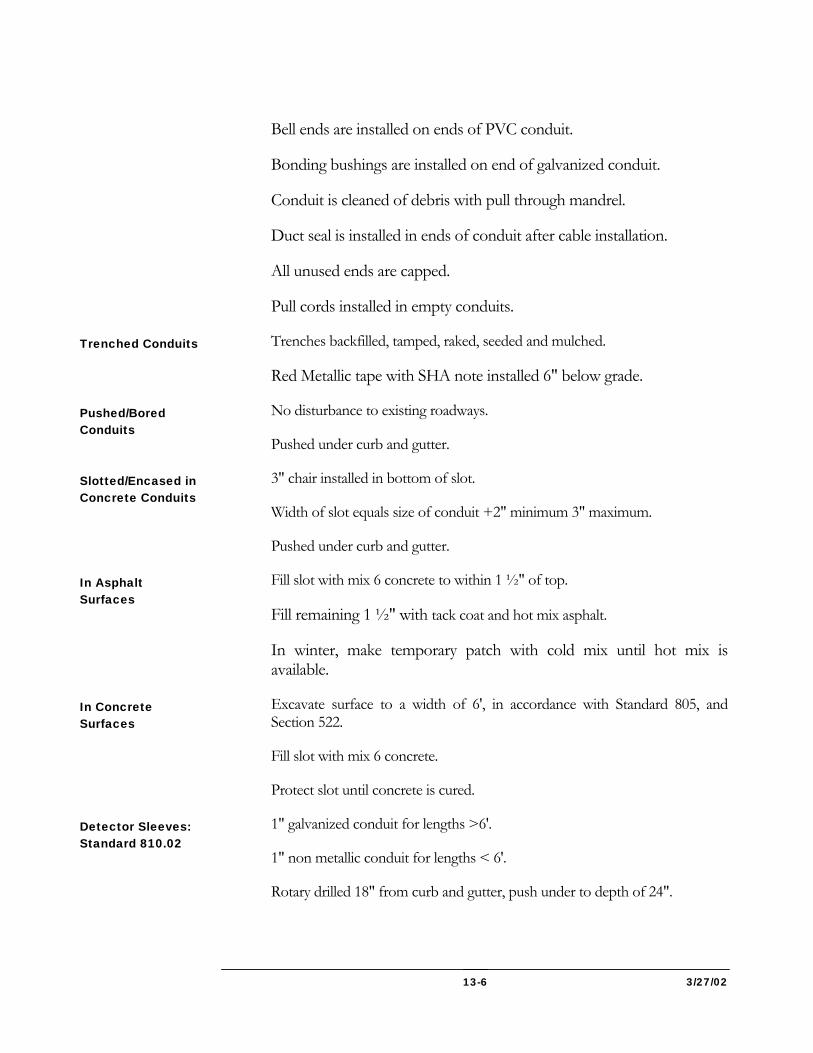
3/27/02 13-6
Bell ends are installed on ends of PVC conduit.
Bonding bushings are installed on end of galvanized conduit.
Conduit is cleaned of debris with pull through mandrel.
Duct seal is installed in ends of conduit after cable installation.
All unused ends are capped.
Pull cords installed in empty conduits.
Trenches backfilled, tamped, raked, seeded and mulched.
Red Metallic tape with SHA note installed 6" below grade.
No disturbance to existing roadways.
Pushed under curb and gutter.
3" chair installed in bottom of slot.
Width of slot equals size of conduit +2" minimum 3" maximum.
Pushed under curb and gutter.
Fill slot with mix 6 concrete to within 1 ½" of top.
Fill remaining 1 ½" with tack coat and hot mix asphalt.
In winter, make temporary patch with cold mix until hot mix is available.
Excavate surface to a width of 6', in accordance with Standard 805, and Section 522.
Fill slot with mix 6 concrete.
Protect slot until concrete is cured.
1" galvanized conduit for lengths >6'.
1" non metallic conduit for lengths < 6'.
Rotary drilled 18" from curb and gutter, push under to depth of 24".
Trenched Conduits
Pushed/Bored Conduits
Slotted/Encased in Concrete Conduits
In Asphalt Surfaces
In Concrete Surfaces
Detector Sleeves: Standard 810.02
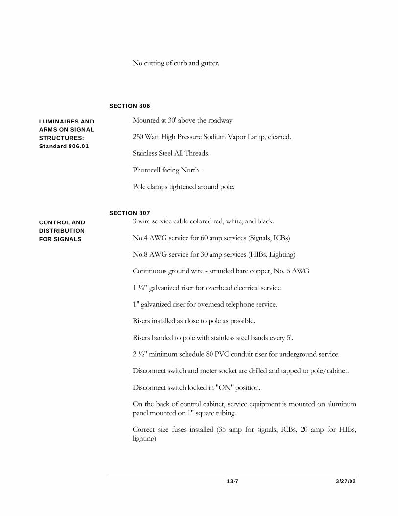
3/27/02 13-7
No cutting of curb and gutter.
SECTION 806
Mounted at 30' above the roadway
250 Watt High Pressure Sodium Vapor Lamp, cleaned.
Stainless Steel All Threads.
Photocell facing North.
Pole clamps tightened around pole.
SECTION 807
3 wire service cable colored red, white, and black.
No.4 AWG service for 60 amp services (Signals, ICBs)
No.8 AWG service for 30 amp services (HIBs, Lighting)
Continuous ground wire - stranded bare copper, No. 6 AWG
1 ¼” galvanized riser for overhead electrical service.
1" galvanized riser for overhead telephone service.
Risers installed as close to pole as possible.
Risers banded to pole with stainless steel bands every 5'.
2 ½" minimum schedule 80 PVC conduit riser for underground service.
Disconnect switch and meter socket are drilled and tapped to pole/cabinet.
Disconnect switch locked in "ON" position.
On the back of control cabinet, service equipment is mounted on aluminum panel mounted on 1" square tubing.
Correct size fuses installed (35 amp for signals, ICBs, 20 amp for HIBs, lighting)
LUMINAIRES AND ARMS ON SIGNAL STRUCTURES: Standard 806.01
CONTROL AND DISTRIBUTION FOR SIGNALS
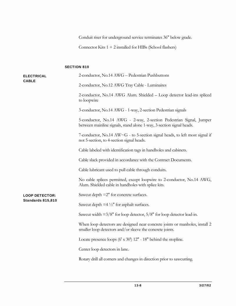
3/27/02 13-8
Conduit riser for underground service terminates 36" below grade.
Connector Kits 1 + 2 installed for HIBs (School flashers)
SECTION 810
2-conductor, No.14 AWG – Pedestrian Pushbuttons
2-conductor, No.12 AWG Tray Cable - Luminaires
2-conductor, No.14 AWG Alum. Shielded – Loop detector lead-ins spliced to loopwire
3-conductor, No.14 AWG - 1-way, 2-section Pedestrian signals
5-conductor, No.14 AWG - 2-way, 2-section Pedestrian Signal, Jumper between mainline signals, stand alone 1-way, 3-section signal heads.
7-conductor, No.14 AW~G - to 5-section signal heads, to left most signal if not 5-section, to 4-section signal heads.
Cable labeled with identification tags in handholes and cabinets.
Cable slack provided in accordance with the Contract Documents.
Cable lubricant used to pull cable through conduits.
No cable splices permitted, except loopwire to 2-conductor, No.14 AWG, Alum. Shielded cable in handholes with splice kits.
Sawcut depth =2" for concrete surfaces.
Sawcut depth =4 ½" for asphalt surfaces.
Sawcut width =3/8" for loop detector, 5/8" for loop detector lead-in.
When loop detectors are designed near concrete joints or manholes, install 2 smaller loop detectors and/or sleeve the concrete joints.
Locate presence loops (6' x 30') 12" - 18" behind the stopline.
Center loop detectors in lane.
Rotary drill all corners and changes in direction prior to sawcutting.
ELECTRICAL CABLE
LOOP DETECTOR: Standards 815,810
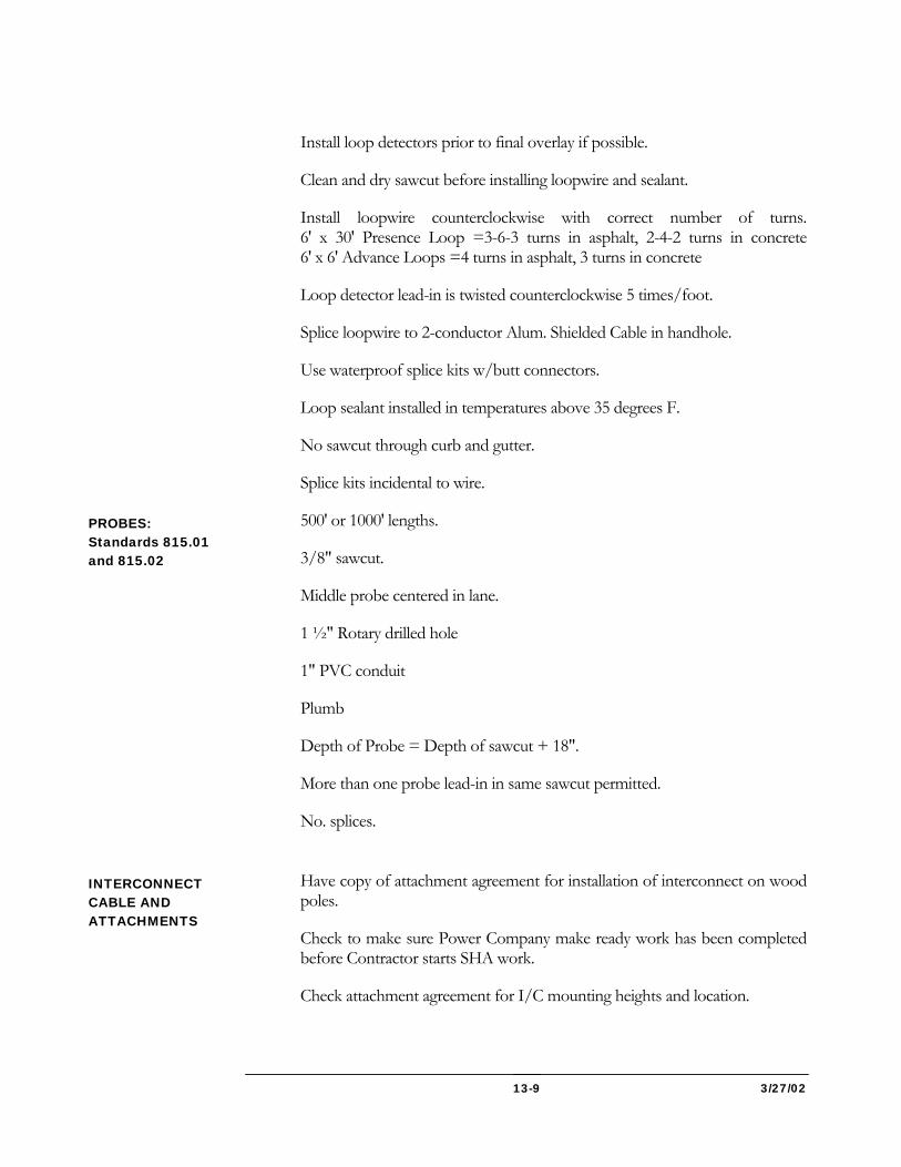
3/27/02 13-9
Install loop detectors prior to final overlay if possible.
Clean and dry sawcut before installing loopwire and sealant.
Install loopwire counterclockwise with correct number of turns. 6' x 30' Presence Loop =3-6-3 turns in asphalt, 2-4-2 turns in concrete 6' x 6' Advance Loops =4 turns in asphalt, 3 turns in concrete
Loop detector lead-in is twisted counterclockwise 5 times/foot.
Splice loopwire to 2-conductor Alum. Shielded Cable in handhole.
Use waterproof splice kits w/butt connectors.
Loop sealant installed in temperatures above 35 degrees F.
No sawcut through curb and gutter.
Splice kits incidental to wire.
500' or 1000' lengths.
3/8" sawcut.
Middle probe centered in lane.
1 ½" Rotary drilled hole
1" PVC conduit
Plumb
Depth of Probe = Depth of sawcut + 18".
More than one probe lead-in in same sawcut permitted.
No. splices.
Have copy of attachment agreement for installation of interconnect on wood poles.
Check to make sure Power Company make ready work has been completed before Contractor starts SHA work.
Check attachment agreement for I/C mounting heights and location.
PROBES: Standards 815.01 and 815.02
INTERCONNECT CABLE AND ATTACHMENTS
3/27/02 13-10
No splices.
Maintain horizontal clearances from other cables on utility poles. (NEC, NESC, Maryland High Voltage Act) 10' from primary cable (voltage> 750) 40" from secondary cable (voltage <750) 3' from cable TV and 2' from telephone cables.
Telephone cable is lowest on pole.
Correct hardwire installed.
Pole backguyed where changes in direction of cable occur, in accordance with utility company requirements.
Messenger span grounded at every pole with a transformer, or every 4th pole.
Twist O/H interconnect cable between poles 3 times per foot. I/C cable slack match existing cables.
Self supporting cable removed prior to routing through conduits and risers into the cabinet.
Tags installed on J-hooks on utility poles identifying SHA cable.
SECTION 811
Concrete collar with rebar installed around handhole. (8" x 8")
Installed flush with grade.
Ground strap between lid and frame.
Handle assembly is offset, locking.
Bonding bushings on all galvanized conduits.
Ground wire between bonding bushings and ground strap on lid.
Conduit - maximum 2" projection from sides.
Conduit - maximum 6" projection from top of sump
All openings between conduit and handhole wall to be parged.
18" aggregate sump installed in bottom of handhole.
HANDHOLES: Standard 811
3/27/02 13-11
Conduit sealed with duct seal after cable installations are complete.
Unused conduit ends capped.
When handholes set in sidewalks, excavate sidewalk joint to joint, no collar installed.
J-hooks installed.
SECTION 812
Wood post installed 5' in ground, plumb.
4” x 6” wood posts to be drilled to give breakaway feature on 6" side
Signs mounted on smaller sides of wood posts.
Surfaces backfilled and tamped.
SECTION 813 - SIGNS ON TRAFFIC SIGNAL PROJECTS
Correct location per plans
17' - 19' roadway clearance.
Does not block signal display?
Span mounted signs tethered on ¼” bottom span wire if called for on plans
7' Clearance from top of grade, 5' clearance in rural areas with no pedestrian traffic.
Locate 15' from road edge (no curb)
Locate 2' minimum, 6' desirable behind curb face.
Installed on wood posts with stainless steel thru bolts.
SECTION 814 - SIGNALS Mounted at 10' above roadway.
Aimed at crosswalks
Set back a minimum of 2' behind face of curb.
12' - 15' roadway clearance.
Attached with stainless steel bands.
WOOD SIGN SUPPORTS
Overhead Mounted Signs
Ground Mounted Signs
Pedestrian Signals
Pole Mounted Signals
3/27/02 13-12
1" hole drilled in pole at bottom plate of signal for cable installations.
Set back a minimum of 2' behind face of curb.
17' - 19' roadway clearance.
Balance adjusters installed for span wire mounted signals
Tunnel visors installed.
Cut asto tube 1 ½” above signal heads for mast arm mounted signals.
Signal heads aimed in conformance to MUTCD requirements.
SECTION 816 - TRAFFIC SIGNAL CONTROLLERS AND CABINETS Foundation matches specified cabinet size (5 or 6)
Standard elbows installed (2-4", 2-2")
10' ground rod installed, projecting 3" above base.
One piece ground clamp installed on ground rod.
Continuous groundwire between ground rod and neutral bar.
Neoprene gasket installed between foundation and cabinet.
Intersection prints and cabinet wiring plan in cabinet.
Field wiring labeled with identification tags.
Bell ends installed on PVC conduit.
Terminal spades installed on all field wires.
Foundation paid separately under concrete foundation.
M-size cabinet mounted at 30" above grade
P-size cabinet mounted at 36" above grade.
3' x 4' concrete pad installed.
3" coupling/3" LB installed for M-size cabinet, 2" coupling/LB for G-size.
All fitting wire brushed and spray galvanized.
Span Wire/Mast Arm Mounted
Base Mounted Cabinets
Pole Mounted Cabinets
3/27/02 13-13
2-3/4" Stainless steel bands per bracket to install cabinet on structure
SECTION 817
Push buttons installed at 36"
Push button signs installed at 48"
Push buttons located in position that indicates which crosswalk is activated by button.
Holes drilled in poles to provide cable and wire entrances.
Push buttons installed using stainless steel bands.
SECTION 818 - SIGNAL STRUCTURES (Standards 818, 821) Minimum placement 2' from closed curb section of roadway, 6' from open travel edge.
Signal pole bases grouted.
Hardware installed, pole caps, arm caps, handhole covers, feet covers, etc.
Positive rake to Structure as needed to get clearance over road.
End of arm above vertical plane after load is applied.
2 piece mast arm connected with ¾” hole and 5/8” stainless steel thru bolt.
Rubber grommet holes for wire are installed a maximum of 12" from signal, on the bottom of the arm.
3" Weatherheads installed for wire
Correct size pole installed. Transformer Base installed.
SECTION 819 3/8” Span wire for signal/sign installations
¼” Span wire for tether or messenger span.
Messenger rings are spaced 8" apart.
Messenger rings minimum size is 3" diameter, use larger if needed. (Maximum fill is 50% of ring)
PUSH BUTTONS AND SIGNS
General Specifications
Mast Arms and Poles
Strain Poles
Pedestal Poles
STEEL SPAN WIRE
3/27/02 13-14
Double wrap span wire at each pole.
Free end of span shall be 2' in length and secured to traversing span by a three bolt clamp and one piece service sleeve.
OVERHEAD SIGN STRUCTURES GENERAL This work will consist of furnishing and constructing overhead sign structures and other appurtenances as specified in the Contract Documents or as directed by the Project Engineer.
The purpose of the inspection of all sign structures is to assure that structures are installed in accordance with the Contract Documents and provide the documentation for future reference. The complete hands-on inspection of all overhead sign structure components, as outlined hereafter, shall be performed as the work progresses.
When specified in the Contract Documents, the Contractor shall provide the personnel and equipment for the hands-on inspection by the Administration Inspector.
Inspection will include but is not limited to the following: concrete foundation, anchor bolts, base plates, tubing, welded/bolted connections, cantilever arms, overhead trusses, column-to-truss connections, sign connections, electrical wiring and luminaires paint coating on Aesthetic Structures, etc.
Inspections will be conducted by Administration personnel and recorded daily on a separate I.D.R.
OVERHEAD SIGN STRUCTURES CHECKLIST See that
All Inspectors involved have been trained by SHA/OMT Personnel.
All materials are approved by OMT.
Approved plans and working drawings are on hand.
Contractor’s layout is checked and all elevations are verified.
All components of the structure are checked for any dents, rust, weld cracks, missing parts, condition of galvanizing, and collision damage. Any defects located will be reported to the Contractor for immediate repair.
All welds which show indication of rust staining or where cracks are evident are referred to the Metals Section/OMT.
Before Construction
3/27/02 13-15
All appropriate measuring devices, testing equipment, forms and reference materials are on hand.
See that
Foundation excavation, reinforcement, bolt circle and template for setting anchor bolts are checked.
Grade area at foundation conforms to standards.
Placement of concrete mix is checked and tests are performed as required. After placement assure anchor bolts are plumb and at correct elevation.
If reusing an existing foundation, OMT Metals Section is contacted for inspection after old structure is removed.
Concrete is properly cured and reaches required strength.
Anchor bolts, leveling nuts, base plates, posts, etc. are checked for proper alignment.
The condition of hand holes, hand hole covers, electrical wiring and wiring components is checked.
Cantilever arm to tubing connection, including connection plates, are checked for alignment, missing bolts, looseness and gaps.
Truss connections to tubing including shim plates, U-bolts including the seating angle and welds if applicable, splice plates and bolts are all checked. Report missing bolts to Contractor.
Truss is installed with camber in correct direction.
Sign attachments are checked for: missing or broken post clips, U-bolts and other bolts on extruded or sheet aluminum panels, sign face extrusions for damage, short or missing sign panel supports, lighting supports for attachments with the truss chords, and structural condition of luminaries.
The Contractor maintains proper traffic control in compliance with the details shown in the Contract Documents.
The Inspector completes a separate IDR for sign structure work. (No other work will be included on this IDR.)
During Construction
3/27/02 13-16
The complete structure and components are inspected for alignment, tightness of bolts, and condition of structure support. Any defects located will be reported to the Contractor for immediate repair.
See that
A Final Inspection and repair report of each structure, using the appropriate form, including pictures, will be prepared by the Project Engineer at the completion of the contract or prior to the opening to traffic, whichever is earlier.
Records 1. The Final Inspection Report and pictures will be included in the Sketch Book
forwarded to the District Office.
2. The District Engineer will forward a copy of the Final Inspection Report and pictures to the Division Chief, Traffic Engineering Division of the Office of Traffic and Safety.
REFERENCES TO STANDARD SPECIFICATIONS FOR CONSTRUCTION & MATERIALS
*Foundations -Section 801 Concrete Foundations
**Structures -Section 803 Overhead Sign Structures
Electrical -Section 804 Grounding
Electrical -Section 805 Electrical Conduit and Fittings
Electrical -Section 806 Luminaries and Lamps
Electrical -Section 810 Electrical Wire, Cable and Connectors
Electrical -Section 820 General Electric Work and Testing
**Also see: -Section 430 Metal Structures
-Section 433 Bridge Mounted Sign Supports
*Also see: -Section 421 Reinforcement for Concrete Structures
After Construction
3/27/02 13-17
ELECTRICAL CONDUIT AND FITTINGS CHECKLIST See that
All materials are approved by OMT.
Approved working drawings are on hand
Uniform grade for the conduit is established between drainage points.
See that
No section of the conduit is flattened or distorted.
All cut ends are free from burrs.
Curvature between pull points is not too great.
All joints are watertight.
Expansion couplings are provided at proper intervals and at every point where the conduit crosses an expansion joint in a structure.
Expansion fittings in a metallic conduit are bridged with bare No. 8 copper wire.
The conduit is adequately supported.
A conduit to be encased in concrete is rigidly held while the concrete is being placed.
See that
The conduit is free of obstructions.
The ends of conduit are protected by temporary closures.
Pull wire or cord is installed.
Water drains freely from the conduit at low points in the grade.
A conduit is a tube or pipe that encloses and protects an electrical wire or cable. The tube or pipe may be metallic or of some nonmetallic material.
Any conduit must be adequately sized and free of short bends or kinks. If there is a bend, the radius of the conduit must not be less than the minimum specified value. Also, there is a limit to the total amount of curvature permitted between pull points,
Before Construction
During Construction:
After Construction
3/27/02 13-18
or in the distance for which their wire or cable is pulled through the conduit. At a joint, the ends of the conduit sections must be smooth because burrs increase the difficulty of pulling the wire or cable or damage to the insulation. For this reason, all cut ends of sections must be reamed, and ends of sections of nonmetallic conduits must be tapered with an approved tool.
A conduit must move freely at designated intervals and where the conduit crosses an expansion joint in a structure. To ensure a continuous path for conducting electricity, the expansion fitting in a metallic conduit must be bridged by bare No. 8 copper wire.
Every conduit must be checked after being constructed for stoppage at any point. This check can be made by a pull through mandrel type device. Another similar check should be made just before placing the electric wire or cable in the conduit or before putting the line into service. If the wire or cable is not to be put immediately in the conduit, a pull wire or cord must be installed and left in place to draw the wire or cable through the conduit in the future. Also, the ends of the conduit and any other openings must be left closed.
Records: Records should include measurement and location of conduit and fittings. Conduit is either paid as Lump Sum when constructed into the concrete structures or by length as specified in the Contract Documents. Measurement of boxes is usually on the each basis, except when included in the Lump Sum on structures.
UTILITIES (SECTION 875 TO 899) CHECKLIST
See that
Approved Utility Plans, a copy of the agreement, with the estimate, and the permit are on hand.
Notice to Proceed (NTP) has been issued to the Utility.
Starting date for work is scheduled.
It is clearly understood what work is to be done by the Utility and by others.
Name and phone number of “Contact person” for each Utility is recorded.
Preliminary measurements and sketches of the location of existing utilities have been made and documented jointly by the District Office or the Project Engineer and the Utility Representative.
See that
Records are kept as required by CD 07220.800.01
Before Construction
During Construction
3/27/02 13-19
Necessary measurements and sketches are made and recorded.
Daily work reports and bills submitted by the utility are checked as received.
Delays and conflicts are reconciled.
Work is done in conformity with plans.
“As Built” utility plans are kept up to date.
The Utility is informed of all revisions to highway plans.
Backfill is in conformance with the specifications.
Completion date is recorded
See that
Summary of work is submitted to the District Engineer.
“As Built” utility plans are submitted to the District Engineer.
Bills for work are in good order and checked.
Accurate documentation for measurements and payment is on file.
POLICY The Administration has an extensive written statement of policy known as the “Utility Policy”, which regulates public utility installations running longitudinally with or crossing such highways. Information on these policies, practices, and procedures, including those formulated and enforced by the Federal Highway Administration, is available through the Utilities Team of the Office of Construction.
GENERAL The procedures set forth herein apply to all public and private utility facilities, whether overhead, on the surface, or underground, and whether on privately owned or leased rights-of-way or on public highway rights-of-way. Such utilities include electric power transmission and distribution lines, telephone and communication lines, fiber optic lines, and pipe lines for water, sanitary sewers, storm drains, gas, oil, or petroleum products.
The procedures given in this chapter deal with the duties and responsibilities of the Project Engineer and the Inspectors on a highway construction project as they are related to the operations of installing, protecting, relocating, or removing any of the various types of utilities that may be in any way affected by the highway construction. A brief outline will also be given of the preliminary work and negotiations that must be accomplished before the start of the utility work.
After Construction
3/27/02 13-20
PRELIMINARY ARRANGEMENTS In order to avoid unnecessary delays and costs in constructing highway improvements, it is essential that utility companies be advised well in advance of any improvements that will affect their facilities. Then arrangements can be made in advance of actual highway construction for the adjustments and changes that will be needed. In some cases, these adjustments and changes can be started or even completed before beginning the highway work. To accomplish this, the Office of Planning and Program Development holds periodic regional meetings to which representatives of the utility companies are invited, and at which the Administration’s proposed construction schedule is presented.
Later, when plans for a specific project are available and not more than 30 percent complete, copies are sent to the District Engineer for distribution to the utility companies for the first time. Again, when they are 65 percent complete a second set of plans is sent for utility design purposes. At 85 percent a third set of plans is sent to the utility for final design considerations. During this time the Utility company and the Administration have completed most of the preliminary arrangements such as agreements, areas of responsibility, estimates and division of costs, Federal approval where necessary, and approval of utility plans, etc. The Administration makes arrangements to have the necessary funds allocated for the Administration’s portion of the utility work. Final signed copies of the highway construction plans are forwarded to the Utility, and a formal permit is issued for them to do their work in the Administration’s right-of-way. The District Engineer will also keep the utility advised as to the date of advertisement of the contract and invite them to attend the pre-bid conference. After award of the contract the District Engineer will advise the Utility of the name of the successful bidder and arrange for the Utility Representative to attend the pre-construction conference. The District Engineer will then advise the Utility of the date of the contract’s NTP. When the Contractor moves in and starts work on the job, the District Engineer will inform the Utility of the name, office location, and phone number of the Project Engineer. The Project Engineer should get from the District Utility Engineer the name and phone number of the person to contact for each Utility.
INSPECTION AND CONTROL OF WORK It is at this point that the Construction Inspection Division Personnel (CID) assigned to the project become involved. Their duties and the responsibilities that follow will be discussed in detail.
Plans and Permit The Project Engineer must have an approved set of the Utility’s plans, a copy of the agreement, and a copy of the estimated cost of the utility work showing the portion to be paid for by the Administration, if any. The Project Engineer should also have a copy of the permit issued to the Utility to do the work, and a copy of the NTP. The Project Engineer must make sure the work is not started until after the Utility has been given NTP. The Federal government will not reimburse the Administration for the cost of any utility work done before the issuance of the NTP.
3/27/02 13-21
Work Orders The Project Engineer must have a clear understanding of the portions of work that are to be done by the utility’s forces and those done by the State’s Contractor or its own forces. He or she must also ascertain if the work to be done by the utility’s forces at the State’s expense is to be done under a separate work order of the Utility or whether it will be billed to the Administration as a percentage of all the work they are to do. If the work is to be done under a separate work order, then the Inspector is to keep separate records of the labor, equipment, materials, and other data related to each work order.
Schedule The Inspector must arrange with the Utility foreman a time schedule in advance of the date and time when the utility work is to start and at what location. The foremen should also keep the Inspector posted as the work progresses.
Documentation The importance of complete records and documentation cannot be overemphasized. It must be possible to accurately check bills presented for the work upon completion. The Inspector should keep a detailed diary pertaining to the progress of the work in addition to complete records of material used, removed or salvaged, hours of labor, equipment used, and locations of work being done. These should be checked against daily work reports and bills submitted by the Utility, and any major discrepancies should be reported at once to the District Utility Engineer. Before any utility work starts, the Project Engineer must make sure that either he or she or the District Utility Engineer has recorded all necessary measurements and sketches to properly document the existing location of overhead and surface facilities. When the work commences, the Inspector should obtain similar data for underground structures as they become available. All such measurements should locate the center line of the facility relative to the center line and station of the existing road. If possible, all such measuring and sketching should be done jointly with a representative of Utility, and both representatives should sign and date the notes. Also, as any of these facilities are removed, added to, changed, or adjusted in any way, additional measurements and sketches should be made to keep the documentation complete and up to date. The documentation can be shown on the Inspector’s Daily Report and the Utility foreman should sign such reports. A summary of this data should also appear on the Daily Construction Log for the project. The Project Engineer should also obtain from the Utility foreman copies of his or her daily work reports as specified in the utility agreement.
Test Pits The Project Engineer is responsible for approving the number, size, and location of test pits and for making measurements and sketches to be used as a basis of payment unless they are to be paid for on a force account basis. He must make sure the test pits and excavation for all underground structures are properly backfilled as required by the Specifications.
3/27/02 13-22
Delays The Project Engineer must record and report promptly any delays that occur and do everything possible to resolve the delays, as they could be the basis for claims.
Check of Work The Project Engineer should check the alignment and grade of all installations, as well as clearance of overhead wires and cover for underground structures, and see that all work done is in conformity with what is shown on the approved plans. No deviation from or revision to these plans may be permitted without prior written approval of the Administration.
Protection of Services All utilities must be protected against damage, and uninterrupted service must be maintained.
Cooperation between Parties The Inspector must do everything possible to resolve any conflicts between various utilities working on the job, as well as between the utilities and the highway Contractor, and to promote and facilitate the utmost cooperation between them. Any conflicts or lack of cooperation should be fully documented and reported to the District Office at once.
Changes Involving Third Party Work If a field change requires immediate work for any third party work prior to a formal execution of the Change Order, the Inspector will initiate and maintain extensive documentation for all labor, materials and equipment (documentation should comply with TC 7.03 Force Account Work of the Specifications). The documentation will be very important if the Contractor and Administration cannot agree on the cost for the work.
The Project Engineer should immediately notify the District Utility Engineer of any changes involving third party work.
Overruns If overruns develop during the course of the work, and they amount to 10 percent or more of the total estimated cost of the utility work, then it will be necessary for the Project Engineer to advise the District Engineer, who must then submit an additional Form 30, “Request for Authority to Contract for Expenditure of Funds,” to cover the additional costs.
Betterment Generally, the State will not participate in the cost of betterment, and it is the responsibility of the Utilities Section to see that such items are not paid for. Betterment include items such as improved class, type, or height of supporting poles or structures; electrical conductors of higher conductivity; increased size or number of
3/27/02 13-23
conductors in communication cables; improved class or increased size of pipes and conduits; and the extension of facilities beyond the highway improvements.
Completion of Third Party Work The Project Engineer will schedule a Final Inspection of all utility work performed. The Contractor and the utility representative will attend. A punch list of any required corrections will be provided by the Utility. Upon completion of any corrections, the Project Engineer will schedule another Final Inspection. Once all corrections are satisfactorily completed, the Utility shall submit a letter of acceptance of the work to the District Engineer.
Completion of Work The Inspector must also have a record of the date of completion of the work, since no bills will be approved for work done after that date.
Bills When either monthly or final bills are received from the utility, the District Engineer must first have them checked by the Project Engineer.
Summary of Work Done Upon completion of the work the Inspector should summarize in a brief written statement to the District Engineer, the work done and the extent to which it agreed or disagreed with the proposed work as shown on the originally approved utility plans. At this time, a set of marked up “As Built” utility plans should also be submitted to the District Engineer.
Records: Records for utility work include those required to check utility bills submitted, as these are the basis of payment for this work. These include records of labor and equipment and of materials used, removed, and salvaged. Records must also document any delays, work stoppages, lack of cooperation between various work forces, lack of conformity to plans, and overruns or underruns. A detailed and accurate diary is required.
CONSTRUCTION CHANGE ORDERS RELATIVE TO UTILITY WORK The following procedure is required when Construction Change Orders, involve utility work on Administration construction projects:
1. The District Engineer, or designee, will notify the District Utilities Engineer (DUE) with regard to the scope of the extra work.
2. The DUE will contact the affected Utility Company for concurrence of the proposed extra utility work. Upon the Utility Company’s documented concurrence, the District Engineer, or designee, will prepare the Change Order (CO), and issue the DUE a copy. All COs for utility work will include a statement from the DUE which addresses the Administration’s and the Utility

3/27/02 13-24
Company’s cost responsibility statement, the DUE will transmit a copy of CO to the Chief of the Utility Section, Office of Construction. NOTE: For specific guidelines in the preparation of COs, refer to CONSTRUCTION DIRECTIVE 07220-800-01
3. The Utilities Section will review the CO to ensure that the cost responsibility statement has been addressed.
4. Upon execution of the CO, the Utilities Section will forward a copy of the CO to the Receipts and Disbursements Section for billing purposes.
5. Upon payment for the extra work performed by the Contractor, the Receipts and Disbursement Section will bill the Utility Company based upon the Utility Company’s cost responsibility for the extra work. The Receipts and Disbursement Section will also distribute copies of the Utility Company billing to the DUE and the Utilities Section.