Embed Size (px)
Citation preview

RETAINING WALLS
(RW)
1 1
RE
TA
ININ
G W
AL
LS
DATE:
STATE HIGHWAY ADMINISTRATION
DEPARTMENT OF TRANSPORTATION
STATE OF MARYLAND
STANDARD NO. SHEET OF
SHA FHWA
REVISIONS
APPROVAL
FHWA APPROVAL
DATE:
STANDARD RETAINING WALLGENERAL NOTES
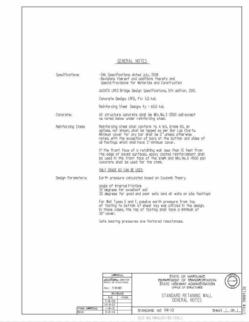
GENERAL NOTES
Specifications:
-Revisions thereof and additions thereto and
Special Provisions for Materials and Construction
Concrete:
Earth pressure calculated based on Coulomb Theory.
All structure concrete shall be Mix. No. 3 (3500 psi) except
as noted below under reinforcing steel.
Reinforcing Steel: Reinforcing steel shall conform to A 615, Grade 60. All
splices, not shown, shall be lapped as per Bar Lap Charts.
Minimum cover for any bar shall be 2’’ unless otherwise
noted, with the exception of bars at the bottom and sides of
all footings which shall have 3’’ minimum cover.
Design Parameters:
Angle of Internal Friction:
33 degrees for excellent soil
30 degrees for good and poor soils (and all walls on pile footings)
7/8/83
7-16-02
Reinforcing Steel Design: fy = 60.0 ksi.
For Wall Types E and F, passive earth pressure from top
of footing to bottom of shear key was utilized in the design.
In these cases, the top of footing shall have a minimum of
30’’ cover.
Safe bearing pressures are factored resistances.
10-9-07
10-9-2007
LR D
VERIFIED
FOFFICE OF STRUCTURES
DIRECTOR
OFFICE OF STRUCTURES
1-18-12
-SHA Specifications dated July, 2008
AASHTO LRFD Bridge Design Specifications, 5th edition, 2010.
Concrete Design: LRFD, f’c= 3.0 ksi.
If the front face of a retaining wall less than 10 feet from
the edge of paved surfaces, epoxy coated reinforcement shall
be used in the front face of the stem and Mix. No. 6 (4500 psi)
concrete shall be used for the stem.
ONLY GRADE 60 CAN BE USED.
3-21-14
OLD NO. RW(6.02)-83-133(L)
RW-101

6/8/83
1 1
RE
TA
ININ
G W
AL
LS
Notes:
If in the length of a wall the type of wall changes
and provides for a different thickness of stem,
greater than the least wall thickness.
alternative is selected.
1.
2.
3.
Wall
TypeH A B C D
6’-0’’
8’-0’’
10’-0’’
12’-0’’
14’-0’’
16’-0’’
18’-0’’
20’-0’’
1’-0’’
1’-0’’
1’-0’’
1’-0’’
1’-3’’
1’-9’’
1’-0’’
1’-0’’
E
1’-0’’
1’-0’’
1’-3’’
1’-3’’
1’-6’’
1’-6’’
1’-6’’
c/c#5 @ 1’-0’’
c/c#5 @ 1’-0’’c/c#5 @ 1’-0’’
c/c
c/c
c/c
TYPICAL SECTION
Scale: 1/2 ’’ = 1’-0’’
3’’c
l.
B A C
D
c/c#4 @ 1’-6’’ Typ.
E
H
6’’
6’’
2’’c
l.
F
Rear face plumb, to be dampproofed
from top of footing up to finished
groundline.
2’’ cl.2’’ cl.
A
Rear face plumb, to be dampproofed
from top of footing up to finished
2’’ cl.
Least Wall Type thickness
for a particular total length of wall.
3’-0’’ long.
Top Main Stem
Reinforcement
2-#6’s to follow
slope of wall.
A/2
Footi
ng
Concre
te
Ste
m C
oncre
te
*
*
DETAIL A
Scale: None
(See note 2 below)
*
1’-6’’
2’-0’’
3’-3’’
4’-6’’
5’-6’’
6’-0’’
3’-9’’
5’-0’’
6’-3’’
1’-6’’
#6 @ 1’-0’’
#7 @ 6’’
A-I
A-I I
A-111
A-IV
A-V
A-VI
A-VII
A-VIII
1’-3’’
1’-6’’
10’-3’’
11’-3’’ #8 @ 6’’
DATE:
STATE HIGHWAY ADMINISTRATION
DEPARTMENT OF TRANSPORTATION
STATE OF MARYLAND
STANDARD NO. SHEET OF
SHA FHWA
REVISIONS
APPROVAL
FHWA APPROVAL
DATE:
2’-1
’’
Dowel bar ** **
(Typ.)**
Dowel bar
**
**
c/c#7 @ 1’-0’’
F
2’-2’’
2’-2’’
3’-6’’
3’-6’’
c/c#5 @ 1’-0’’
c/c
c/c
Dowel Bar
Rear Main
Stem Bar
Top
Foot. Bar
c/c#5 @ 1’-0’’
c/c#7 @ 1’-0’’
#8 @ 6’’
#7 @ 6’’
c/c#7 @ 6’’
c/c#7 @ 6’’
c/c#6 @ 6’’
6’-9’’
Front
Top Footing BarRear Dowel Bar
Main Stem Bar
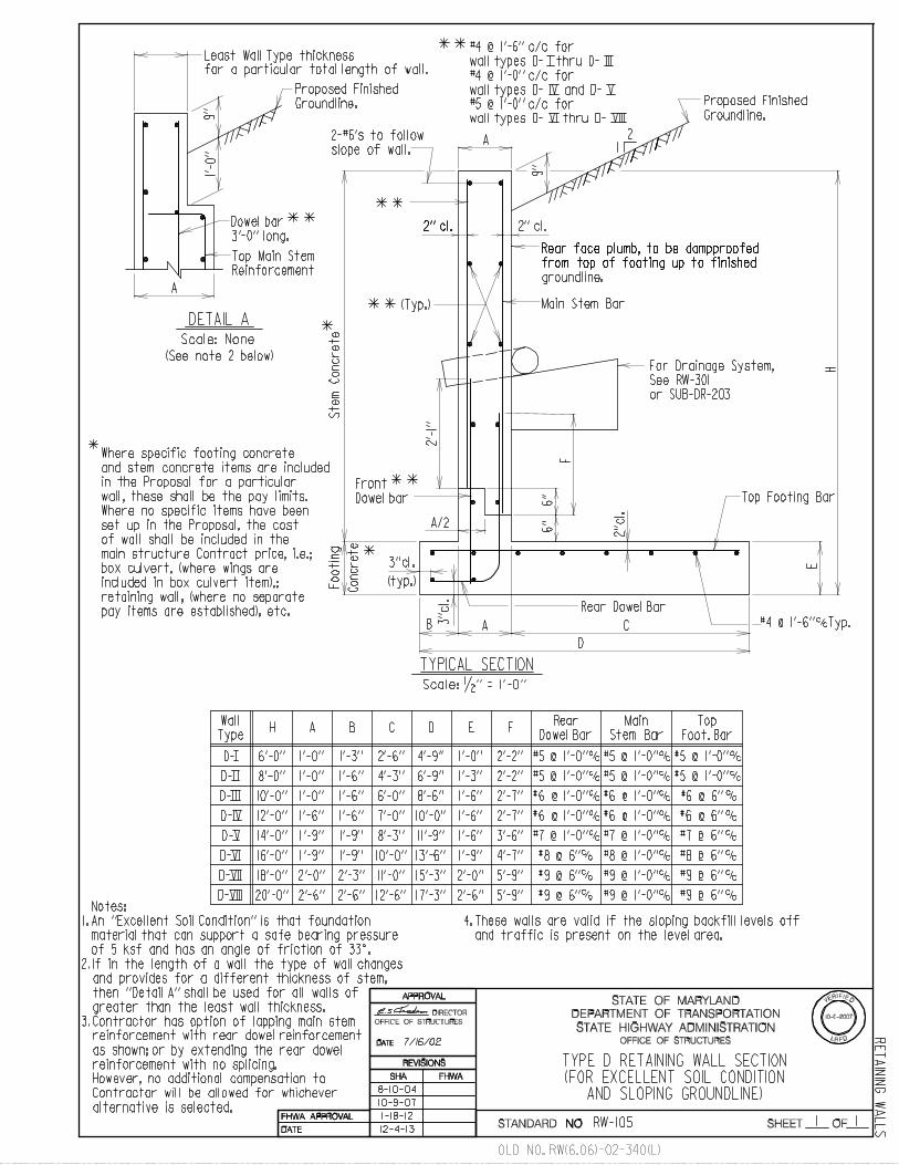
Contractor has option of lapping main stem
reinforcement with rear dowel reinforcement
as shown; or by extending the rear dowel
reinforcement with no splicing.
7’-3’’
c/c#6 @ 1’-0’’
c/c#7 @ 1’-0’’
c/c#8 @ 1’-0’’
c/c#6 @ 1’-0’’
3’-6’’
4’-7’’
c/c#7 @ 6’’
2’-7’’
2’-7’’
Proposed Finished Groundline.9’’
9’’
1’-0
’’
Proposed Finished
Groundline.
TYPE A RETAINING WALL SECTION(FOR EXCELLENT SOIL CONDITION AND
TWO FOOT SURCHARGE)
9’’
9’’
9’’
9’’
7’-9’’
7’-3’’
8’-3’’
9’-3’’
c/c#7 @ 6’’
c/c#6 @ 6’’
c/c#5 @ 1’-0’’
material that can support a safe bearing pressure
A
3’’cl.
For Drainage System,
See RW(0.01)-80-100
or BR-SB(0.01)-80-101
4. These walls are valid if traffic is present on
the level area adjacent to the wall.
DIRECTOR
Where specific footing concrete
and stem concrete items are included
in the Proposal for a particular
wall, these shall be the pay limits.
(typ.)
of 5 ksf and has an angle of friction of 33^.
However, no additional compensation to
Contractor will be allowed for whichever
Where no specific items have been
set up in the Proposal, the cost
of wall shall be included in the
main structure Contract price, i.e.;
box culvert, (where wings are
included in box culvert item),;
retaining wall, (where no separate
pay items are established), etc.
6-21-85
An ’’Excellent Soil Condition’’ is that foundation
then ’’Detail A’’ shall be used for all walls of
5-8-2008
LR D
VERIFIED
FOFFICE OF STRUCTURES
OFFICE OF STRUCTURES
2’-3’’
c/c#6 @ 6’’
#4 @ 1’-6’’ c/c for
wall types A- I thru A- IV
#4 @ 1’-0’’ c/c for
wall types A- V and A- VI
#5 @ 1’-0’’ c/c for
wall types A- VII and A- VIII
8-10-04
5-8-08
1-18-12
12-4-13RW-102
OLD NO. RW(6.03)-83-134

6/8/83
1 1
RE
TA
ININ
G W
AL
LS
Notes:
If in the length of a wall the type of wall changes
and provides for a different thickness of stem,
greater than the least wall thickness.
alternative is selected.
1.
2.
3.
Wall
TypeH A B C D
6’-0’’
8’-0’’
10’-0’’
12’-0’’
14’-0’’
16’-0’’
18’-0’’
20’-0’’
1’-0’’
1’-0’’
1’-0’’
1’-0’’
1’-3’’
1’-9’’
2’-3’’
1’-3’’
1’-6’’
E
1’-0’’
1’-0’’
1’-3’’
1’-3’’
1’-6’’
1’-9’’
1’-9’’
c/c#5 @ 1’-0’’
c/c#5 @ 1’-0’’c/c#5 @ 1’-0’’
c/c
c/c
TYPICAL SECTION
Scale: 1/2 ’’ = 1’-0’’
3’’c
l.
B A C
D
c/c#4 @ 1’-6’’ Typ.
E
H
6’’
6’’
2’’c
l.
F
Rear face plumb, to be dampproofed
from top of footing up to finished
groundline.
2’’ cl.2’’ cl.
A
Rear face plumb, to be dampproofed
from top of footing up to finished
2’’ cl.
Least Wall Type thickness
for a particular total length of wall.
3’-0’’ long.
Top Main Stem
Reinforcement
2-#6’s to follow
slope of wall.
A/2
Footi
ng
Concre
te
Ste
m C
oncre
te
*
DETAIL A
Scale: None
(See note 2 below)
*
1’-6’’
2’-6’’
3’-6’’
4’-6’’
5’-6’’
6’-0’’
4’-3’’
5’-3’’
6’-6’’
1’-6’’
#6 @ 1’-0’’
#7 @ 6’’
B-I
B-I I
B-111
B-IV
B-V
B-VI
B-VII
B-VIII
1’-9’’
2’-3’’
10’-9’’
13’-0’’
DATE:
STATE HIGHWAY ADMINISTRATION
DEPARTMENT OF TRANSPORTATION
STATE OF MARYLAND
STANDARD NO. SHEET OF
SHA FHWA
REVISIONS
APPROVAL
FHWA APPROVAL
DATE:
2’-1
’’
Dowel bar ** **
(Typ.)**
Dowel bar
**
c/c#8 @ 1’-0’’
F
2’-2’’
2’-2’’
3’-6’’
3’-6’’
c/c#5 @ 1’-0’’
c/c
c/c
Dowel Bar
Rear Main
Stem Bar
Top
Foot. Bar
c/c#5 @ 1’-0’’
c/c#7 @ 1’-0’’
#8 @ 6’’
#7 @ 6’’
c/c#7 @ 6’’
c/c#7 @ 6’’
c/c#6 @ 6’’
6’-9’’
Front
Top Footing BarRear Dowel Bar
Main Stem Bar
Contractor has option of lapping main stem
reinforcement with rear dowel reinforcement
as shown; or by extending the rear dowel
reinforcement with no splicing.
3’-6’’
4’-7’’
7’-3’’
c/c#8 @ 6’’
c/c#6 @ 1’-0’’
c/c#7 @ 1’-0’’
c/c#7 @ 1’-0’’
c/c#7 @ 6’’
2’-7’’
2’-7’’
9’’
1’-0
’’
Proposed Finished
Groundline.
Proposed Finished Groundline.9’’
TYPE B RETAINING WALL SECTION(FOR GOOD SOIL CONDITION AND
TWO FOOT SURCHARGE)
9’’
9’’
8’-6’’
7’-6’’
8’-6’’
9’-9’’
c/c#7 @ 6’’
c/c#6 @ 6’’
c/c#5 @ 1’-0’’
material that can support a safe bearing pressure
1’-0’’
1’-0’’
c/c#6 @ 6’’
A
3’’cl.
4. These walls are valid if traffic is present on
the level area adjacent to the wall.
(typ.)
of 4 ksf and has an angle of friction of 30^.
However, no additional compensation to
Contractor will be allowed for whichever
*
Where specific footing concrete
and stem concrete items are included
in the Proposal for a particular
wall, these shall be the pay limits.
Where no specific items have been
set up in the Proposal, the cost
of wall shall be included in the
main structure Contract price, i.e.;
box culvert, (where wings are
included in box culvert item),;
retaining wall, (where no separate
pay items are established), etc.
6-21-02
A ’’Good Soil Condition’’ is that foundation
then ’’Detail A’’ shall be used for all walls of
5-8-2008
LR D
VERIFIED
FOFFICE OF STRUCTURES
DIRECTOR
OFFICE OF STRUCTURES
c/c#6 @ 6’’
** #4 @ 1’-6’’ c/c for
wall types B- I thru B- IV
#4 @ 1’-0’’ c/c for
wall types B- V and B- VI
#5 @ 1’-0’’ c/c for
wall types B- VII and B- VIII
8-10-04
5-8-08
1-18-12
12-4-13
For Drainage System,
See RW-301
or SUB-DR-203
RW-103
OLD NO. RW(6.04)-83-135

6/8/83
1 1
RE
TA
ININ
G W
AL
LS
Notes:
If in the length of a wall the type of wall changes
and provides for a different thickness of stem,
greater than the least wall thickness.
alternative is selected.
1.
2.
3.
Wall
TypeH A B C D
6’-0’’
8’-0’’
10’-0’’
12’-0’’
14’-0’’
16’-0’’
18’-0’’
20’-0’’
1’-0’’
1’-0’’
1’-0’’
1’-0’’
1’-3’’
2’-3’’
2’-3’’
E
1’-0’’
1’-0’’
1’-3’’
1’-3’’
1’-6’’
1’-9’’
1’-9’’
c/c#5 @ 1’-0’’
c/c#5 @ 1’-0’’c/c#5 @ 1’-0’’
c/c
c/c
c/c
c/c
TYPICAL SECTION
Scale: 1/2 ’’ = 1’-0’’
3’’c
l.
B A C
D
c/c#4 @ 1’-6’’ Typ.
E
H
6’’
6’’
2’’c
l.
F
Rear face plumb, to be dampproofed
from top of footing up to finished
groundline.
2’’ cl.2’’ cl.
A
Rear face plumb, to be dampproofed
from top of footing up to finished
2’’ cl.
Least Wall Type thickness
for a particular total length of wall.
3’-0’’ long.
Top Main Stem
Reinforcement
2-#6’s to follow
slope of wall.
A/2
Footi
ng
Concre
te
Ste
m C
oncre
te
*
DETAIL A
Scale: None
(See note 2 below)
*
1’-6’’
2’-6’’
3’-6’’
4’-6’’
5’-6’’
6’-0’’
4’-3’’
5’-3’’
6’-6’’
1’-6’’
#6 @ 1’-0’’
#7 @ 6’’
#7 @ 6’’
C-I
C-I I
C-111
C-IV
C-V
C-VI
C-VII
C-VIII #8 @ 6’’
DATE:
STATE HIGHWAY ADMINISTRATION
DEPARTMENT OF TRANSPORTATION
STATE OF MARYLAND
STANDARD NO. SHEET OF
SHA FHWA
REVISIONS
APPROVAL
FHWA APPROVAL
DATE:
2’-1
’’
Dowel bar ** **
(Typ.)**
Dowel bar
**
c/c#7 @ 1’-0’’
F
2’-2’’
2’-2’’
3’-6’’
3’-6’’
c/c#5 @ 1’-0’’
c/c
c/c
Dowel Bar
Rear Main
Stem Bar
Top
Foot. Bar
c/c#5 @ 1’-0’’
c/c#7 @ 1’-0’’
#8 @ 6’’
#7 @ 6’’
c/c#7 @ 6’’
c/c#7 @ 6’’
c/c#6 @ 6’’
6’-9’’
Front
Top Footing BarRear Dowel Bar
Main Stem Bar
Contractor has option of lapping main stem
reinforcement with rear dowel reinforcement
as shown; or by extending the rear dowel
reinforcement with no splicing.
3’-6’’
4’-7’’
7’-3’’ c/c#7 @ 1’-0’’
c/c#8 @ 1’-0’’
c/c#6 @ 1’-0’’2’-7’’
2’-7’’
9’’
1’-0
’’
Proposed Finished
Groundline.
Proposed Finished Groundline.9’’
TYPE C RETAINING WALL SECTION(FOR POOR SOIL CONDITION AND
TWO FOOT SURCHARGE)
9’’
9’’
8’-9’’
7’-6’’
c/c#7 @ 6’’
c/c#6 @ 6’’
c/c#5 @ 1’-0’’
material that can support a safe bearing pressure
1’-0’’
1’-0’’
c/c#6 @ 6’’
A
3’’cl.
4. These walls are valid if traffic is present on
the level area adjacent to the wall.
(typ.)
of 3 ksf and has an angle of friction of 30^.
However, no additional compensation to
Contractor will be allowed for whichever
*
Where specific footing concrete
and stem concrete items are included
in the Proposal for a particular
wall, these shall be the pay limits.
Where no specific items have been
set up in the Proposal, the cost
of wall shall be included in the
main structure Contract price, i.e.;
box culvert, (where wings are
included in box culvert item),;
retaining wall, (where no separate
pay items are established), etc.
6-8-90
A ’’Poor Soil Condition’’ is that foundation
then ’’Detail A’’ shall be used for all walls of
10-9-2007
LR D
VERIFIED
F
4’-0’’
3’-0’’
2’-3’’
1’-6’’
15’-0’’
12’-6’’
10’-6’’
8’-9’’
OFFICE OF STRUCTURES
DIRECTOR
OFFICE OF STRUCTURES
c/c#6 @ 6’’
** #4 @ 1’-6’’ c/c for
wall types C- I thru C- IV
#4 @ 1’-0’’ c/c for
wall types C- V and C- VI
#5 @ 1’-0’’ c/c for
wall types C- VII and C- VIII
8-10-04
10-9-07
1-18-12
12-4-13
OLD NO. RW(6.05)-83-136(L)
RW-104
For Drainage System,
See RW-301
or SUB-DR-203
DATE:
NO.
SHA FHWA
REVISIONS
APPROVAL
FHWA APPROVAL
DATE:1 1
RE
TA
ININ
G W
AL
LS
Notes:
If in the length of a wall the type of wall changes
and provides for a different thickness of stem,
greater than the least wall thickness.
alternative is selected.
1.
2.
3.
Wall
TypeH A B C D
6’-0’’
8’-0’’
10’-0’’
12’-0’’
14’-0’’
16’-0’’
1’-0’’
1’-0’’
1’-0’’
1’-6’’
1’-9’’ 1’-9’’
1’-9’’
E
1’-0’’
1’-3’’
1’-6’’
1’-6’’
1’-6’’
c/c#5 @ 1’-0’’
c/c#5 @ 1’-0’’c/c#5 @ 1’-0’’
c/c
c/c#4 @ 1’-6’’ Typ.
E
H
6’’
6’’
2’’c
l.
F
Rear face plumb, to be dampproofed
from top of footing up to finished
groundline.
2’’ cl.2’’ cl.
A
Rear face plumb, to be dampproofed
from top of footing up to finished
2’’ cl.
1’-0
’’
Proposed Finished
Groundline.
Least Wall Type thickness
for a particular total length of wall.
3’-0’’ long.
Top Main Stem
Reinforcement
2-#6’s to follow
slope of wall.
A/2
Ste
m C
oncre
teDETAIL A
Scale: None
(See note 2 below)
*
1’-9’’
1’-6’’
2’-6’’ 4’-9’’
1’-9’’
#6 @ 1’-0’’
D-I
D-I I
D-111
D-IV
D-V
D-VI
DATE:
STATE HIGHWAY ADMINISTRATION
DEPARTMENT OF TRANSPORTATION
STATE OF MARYLAND
STANDARD NO. SHEET OF
SHA FHWA
REVISIONS
APPROVAL
FHWA APPROVAL
DATE:
2’-1
’’
Dowel bar ****
(Typ.)**
Dowel bar**
9’’
Proposed Finished
Groundline.
c/c#8 @ 1’-0’’
F
2’-2’’
2’-2’’
3’-6’’
4’-7’’
c/c#5 @ 1’-0’’
c/c
Dowel Bar
Rear Main
Stem Bar
Top
Foot. Bar
c/c#5 @ 1’-0’’
c/c#7 @ 1’-0’’
c/c#8 @ 6’’
c/c#7 @ 6’’
c/c#6 @ 6’’
#6 @ 6’’
FrontTop Footing Bar
Main Stem Bar
9’’
21
Contractor has option of lapping main stem
reinforcement with rear dowel reinforcement
as shown; or by extending the rear dowel
reinforcement with no splicing.
1’-6’’
1’-6’’ c/c#6 @ 1’-0’’ c/c#6 @ 1’-0’’
c/c#8 @ 6’’
2’-7’’
2’-7’’
4.
material that can support a safe bearing pressure
TYPE D RETAINING WALL SECTION(FOR EXCELLENT SOIL CONDITION
AND SLOPING GROUNDLINE)
TYPICAL SECTION
Scale: 1/2 ’’ = 1’-0’’
3’’c
l.
B A C
D
Footi
ng
Co
ncre
te
*
18’-0’’ 2’-3’’2’-0’’ 2’-0’’ c/c#9 @ 1’-0’’5’-9’’ c/c#9 @ 6’’c/c#9 @ 6’’
20’-0’’ 2’-6’’ 2’-6’’ c/c#9 @ 1’-0’’5’-9’’ c/c#9 @ 6’’c/c#9 @ 6’’
D-VII
D-VIII
c/c#6 @ 1’-0’’
c/c#7 @ 1’-0’’
c/c#5 @ 1’-0’’
Rear Dowel Bar
3’’cl.
A
These walls are valid if the sloping backfill levels off
1’-3’’
and traffic is present on the level area.
(typ.)
*
Where specific footing concrete
and stem concrete items are included
in the Proposal for a particular
wall, these shall be the pay limits.
Where no specific items have been
set up in the Proposal, the cost
of wall shall be included in the
main structure Contract price, i.e.;
box culvert, (where wings are
included in box culvert item),;
retaining wall, (where no separate
pay items are established), etc.
of 5 ksf and has an angle of friction of 33^.
However, no additional compensation to
Contractor will be allowed for whichever
7/16/02
8-10-04
An ’’Excellent Soil Condition’’ is that foundation
then ’’Detail A’’ shall be used for all walls of
10-9-07
10-9-2007
LR D
VERIFIED
F
4’-3’’
6’-0’’
7’-0’’
8’-3’’
10’-0’’
11’-0’’
12’-6’’ 17’-3’’
15’-3’’
13’-6’’
11’-9’’
10’-0’’
8’-6’’
6’-9’’
OFFICE OF STRUCTURES
DIRECTOR
OFFICE OF STRUCTURES
2’-6’’
1-18-12
** #4 @ 1’-6’’ c/c for
wall types D- I thru D- III
#4 @ 1’-0’’ c/c for
wall types D- IV and D- V
#5 @ 1’-0’’ c/c for
wall types D- VI thru D- VIII
12-4-13
OLD NO. RW(6.06)-02-340(L)
RW-105
For Drainage System,
See RW-301
or SUB-DR-203

1 1
RE
TA
ININ
G W
AL
LS
Notes:
If in the length of a wall the type of wall changes
and provides for a different thickness of stem,
greater than the least wall thickness.
alternative is selected.
1.
2.
3.
Wall
TypeH A B C D
6’-0’’
8’-0’’
10’-0’’
12’-0’’
14’-0’’
16’-0’’
1’-0’’
1’-0’’
1’-0’’
1’-3’’
1’-6’’ 2’-6’’
3’-0’’
E
1’-0’’
1’-0’’
1’-0’’
1’-6’’
1’-9’’
c/c#5 @ 2’-0’’
c/c#5 @ 2’-0’’c/c#5 @ 2’-0’’
c/c
1’-0
’’
Proposed Finished
Groundline.
Least Wall Type thickness
for a particular total length of wall.
3’-0’’ long.
Top Main Stem
Reinforcement
DETAIL A
Scale: None
(See note 2 below)
1’-9’’
2’-0’’
4’-6’’
4’-9’’
5’-6’’
7’-3’’
7’-3’’
7’-6’’
10’-6’’
11’-6’’
13’-3’’ 2’-0’’
#7 @ 1’-0’’
E-I
E-I I
E-111
E-IV
E-V
E-VI
DATE:
STATE HIGHWAY ADMINISTRATION
DEPARTMENT OF TRANSPORTATION
STATE OF MARYLAND
STANDARD NO. SHEET OF
SHA FHWA
REVISIONS
APPROVAL
FHWA APPROVAL
DATE:
Dowel bar **
F
2’-2’’
2’-2’’
3’-6’’
4’-7’’
c/c
Top
Foot. Bar
c/c#5 @ 2’-0’’
c/c#7 @ 1’-0’’
c/c#8 @ 6’’
c/c#7 @ 6’’
c/c#7 @ 6’’
c/c#5 @ 6’’
#6 @ 6’’
9’’
Contractor has option of lapping main stem
reinforcement with rear dowel reinforcement
as shown; or by extending the rear dowel
reinforcement with no splicing.
1’-9’’
1’-9’’
1’-9’’ c/c#6 @ 1’-0’’
c/c#8 @ 1’-0’’
2’-7’’
3’-6’’
material that can support a safe bearing pressure
G
1’-0’’
1’-0’’
3’-0’’
3’-0’’
2’-0’’
2’-0’’
TYPICAL SECTION
Scale: 1/2 ’’ = 1’-0’’
3’’c
l.
B A C
D
c/c#4 @ 1’-6’’ Typ.
E
H
6’’
6’’
2’’c
l.
F
Rear face plumb, to be dampproofed
from top of footing up to finished
groundline.
2’’ cl.2’’ cl.
A
Rear face plumb, to be dampproofed
from top of footing up to finished
2’’ cl.
2-#6’s to follow
slope of wall.
A/2
Footi
ng
Co
ncre
te
Ste
m C
on
cre
te
**
2’-1
’’
**
(Typ.)**
Dowel bar**
9’’
Proposed Finished
Groundline.
Front
Top Footing Bar
Main Stem Bar
21
Slope As Steep As
Ground Will Allow
G
c/c#5 @ 6’’
TYPE E RETAINING WALL SECTION(FOR GOOD SOIL CONDITIONAND SLOPING GROUNDLINE)
4.
18’-0’’ 3’-6’’2’-3’’ 16’-0’’ 2’-3’’ 5’-9’’ c/c#9 @ 6’’c/c#9 @ 1’-0’’10’-3’’ 3’-0’’
20’-0’’ 4’-3’’2’-9’’ 19’-0’’ 2’-6’’ 5’-9’’ c/c#9 @ 6’’c/c#9 @ 1’-0’’12’-0’’ 3’-0’’
E-VII
E-VIII
7’-6’’
8’-6’’
8’-3’’
A
3’’cl.
Pour against undisturbed material
These walls are valid if the sloping backfill levels off
and traffic is present on the level area.
***
Alternate Hooked Bars
with Straight Bars***
Straight Rear Dowel Bar
Hooked Rear Dowel Bar
c/c#5 @ 1’-0’’
c/c#5 @ 1’-0’’
c/c#7 @ 1’-0’’
Main
Stem Bar
c/c#7 @ 1’-0’’
c/c#6 @ 1’-0’’
c/c#8 @ 1’-0’’
c/c#9 @ 1’-0’’
c/c#9 @ 1’-0’’
Dowel Bar
Hooked Rear
Dowel Bar
Straight Rear
c/c#7 @ 1’-0’’
c/c#7 @ 1’-0’’
c/c#6 @ 1’-0’’
c/c#8 @ 1’-0’’
c/c#9 @ 1’-0’’
c/c#9 @ 1’-0’’
(typ.)
of 4 ksf and has an angle of friction of 30^.
*
Where specific footing concrete
and stem concrete items are included
in the Proposal for a particular
wall, these shall be the pay limits.
Where no specific items have been
set up in the Proposal, the cost
of wall shall be included in the
main structure Contract price, i.e.;
box culvert, (where wings are
included in box culvert item),;
retaining wall, (where no separate
pay items are established), etc.
However, no additional compensation to
Contractor will be allowed for whichever
7/16/02
A ’’Good Soil Condition’’ is that foundation
then ’’Detail A’’ shall be used for all walls of
5-8-2008
LR D
VERIFIED
F
5-8-08
OFFICE OF STRUCTURES
DIRECTOR
OFFICE OF STRUCTURES
** #4 @ 1’-6’’ c/c for
wall types E- I thru E- III
#4 @ 1’-0’’ c/c for
wall types E- IV and E- V
#5 @ 1’-0’’ c/c for
wall types E- VI thru E- VIII
12-4-13
OLD NO. RW(6.07)-02-341
RW-106
For Drainage System,
See RW-301
or SUB-DR-203

1 1
RE
TA
ININ
G W
AL
LS
Notes:
If in the length of a wall the type of wall changes
and provides for a different thickness of stem,
greater than the least wall thickness.
alternative is selected.
1.
2.
3.
Wall
TypeH A B C D
6’-0’’
8’-0’’
10’-0’’
12’-0’’
14’-0’’
16’-0’’
1’-0’’
1’-0’’
1’-0’’
1’-3’’
1’-6’’ 3’-0’’
4’-0’’
E
1’-0’’
1’-0’’
1’-0’’
1’-6’’
1’-9’’
c/c#5 @ 1’-0’’
c/c#5 @ 1’-0’’c/c#5 @ 2’-0’’
c/c
1’-0
’’
Proposed Finished
Groundline.
Least Wall Type thickness
for a particular total length of wall.
3’-0’’ long.
Top Main Stem
Reinforcement
DETAIL A
Scale: None
(See note 2 below)
1’-9’’
2’-0’’
4’-6’’
4’-9’’
5’-6’’
7’-3’’
7’-3’’
7’-6’’
10’-6’’
12’-0’’
14’-3’’ 2’-0’’
#7 @ 1’-0’’
F-I
F-I I
F-111
F-IV
F-V
F-VI
DATE:
STATE HIGHWAY ADMINISTRATION
DEPARTMENT OF TRANSPORTATION
STATE OF MARYLAND
STANDARD NO. SHEET OF
SHA FHWA
REVISIONS
APPROVAL
FHWA APPROVAL
DATE:
Dowel bar **
c/c#8 @ 1’-0’’
F
2’-2’’
2’-2’’
3’-6’’
4’-7’’
c/c
Main
Stem Bar
Top
Foot. Bar
c/c#5 @ 2’-0’’
c/c#7 @ 1’-0’’
c/c#8 @ 6’’
c/c#7 @ 6’’
c/c#7 @ 6’’
c/c#5 @ 6’’
#6 @ 6’’
9’’
Contractor has option of lapping main stem
reinforcement with rear dowel reinforcement
as shown; or by extending the rear dowel
reinforcement with no splicing.
1’-9’’
1’-9’’
1’-9’’ c/c#6 @ 1’-0’’2’-7’’
3’-6’’
G
1’-0’’
1’-0’’
3’-0’’
3’-0’’
2’-0’’
2’-0’’
c/c#5 @ 6’’
material that can support a safe bearing pressure
TYPICAL SECTION
Scale: 1/2 ’’ = 1’-0’’
3’’c
l.
B A C
D
c/c#4 @ 1’-6’’ Typ.
E
H
6’’
6’’
F
Rear face plumb, to be dampproofed
from top of footing up to finished
groundlline.
2’’ cl.2’’ cl.
A
Rear face plumb, to be dampproofed
from top of footing up to finished
2’’ cl.
2-#6’s to follow
slope of wall.
A/2
Footi
ng
Co
ncre
te
Ste
m C
on
cre
te
**
2’-1
’’
**
(Typ.)**
Dowel bar**
9’’
Proposed Finished
Groundline.
Front
Top Footing Bar
Main Stem Bar
21
Slope As Steep As
Ground Will Allow
G
TYPE F RETAINING WALL SECTION(FOR POOR SOIL CONDITIONAND SLOPING GROUNDLINE)
4.
18’-0’’ 5’-0’’2’-3’’ 17’-6’’ 2’-3’’ c/c#9 @ 1’-0’’5’-9’’ c/c#9 @ 6’’3’-0’’10’-3’’
20’-0’’ 6’-3’’2’-9’’ 21’-0’’ 2’-6’’ c/c#9 @ 1’-0’’5’-9’’ c/c#9 @ 6’’3’-0’’12’-0’’F-VIII
F-VII
7’-6’’
8’-6’’
8’-3’’
A
Pour against undisturbed material
3’’cl.
These walls are valid if the sloping backfill levels off
and traffic is present on the level area.
2’’c
l.
***
Alternate Hooked Bars
with Straight Bars***
Straight Rear Dowel Bar
Hooked Rear Dowel Bar
c/c#5 @ 2’-0’’
c/c#5 @ 2’-0’’
Dowel Bar
Hooked Rear
Dowel Bar
Straight Rear
c/c#7 @ 1’-0’’
c/c#8 @ 1’-0’’
c/c#7 @ 1’-0’’
c/c#6 @ 1’-0’’
c/c#9 @ 1’-0’’
c/c#9 @ 1’-0’’
c/c#7 @ 1’-0’’
c/c#8 @ 1’-0’’
c/c#7 @ 1’-0’’
c/c#6 @ 1’-0’’
c/c#9 @ 1’-0’’
c/c#9 @ 1’-0’’
*
Where specific footing concrete
and stem concrete items are included
in the Proposal for a particular
wall, these shall be the pay limits.
Where no specific items have been
set up in the Proposal, the cost
of wall shall be included in the
main structure Contract price, i.e.;
box culvert, (where wings are
included in box culvert item),;
retaining wall, (where no separate
pay items are established), etc.
(typ.)
of 3 ksf and has an angle of friction of 30^.
However, no additional compensation to
Contractor will be allowed for whichever
7/16/02
A ’’Poor Soil Condition’’ is that foundation
then ’’Detail A’’ shall be used for all walls of
5-8-08
5-8-2008
LR D
VERIFIED
FOFFICE OF STRUCTURES
DIRECTOR
OFFICE OF STRUCTURES
** #4 @ 1’-6’’ c/c for
wall types F- I thru F- III
#4 @ 1’-0’’ c/c for
wall types F- IV and F- V
#5 @ 1’-0’’ c/c for
wall types F- VI thru F- VIII
12-4-13
OLD NO. RW(6.08)-02-342
RW-107
For Drainage System,
See RW-301
or SUB-DR-203

E
H
6’’ 6’’
2’’cl.
F
9’’
2’’
cl.
2’’
cl.
A
9’’
2’’
cl.
1’-0’’
Top M
ain
Ste
m
Rein
forc
em
ent
2-#
6’s
to f
oll
ow
slo
pe o
f w
all
.
A/2
Footing
Concrete
Stem Concrete *
DE
TA
IL A
Scale
: N
one
*
2’-1’’
Dow
el
bar*
**
*
(Typ
.)*
*
3’’cl.
D
1’-6
’’1’
-6’’
CB
1
3
1’-0’’ 3’’ cl.
TY
PIC
AL
SE
CT
ION
Sca
le:
1/2
’’
= 1
’-0
’’
3’’c
l.
c /c
#5
@ 1
’-0
’’
T
yp
.
Each
way
ov
er
pil
es
Top F
ooti
ng B
ar
Main
Ste
m B
ar
3 -
#6’s
@ 4
’’ c
/c
3’-
0’’
long.
Least
Wall
Type t
hic
kness
for
a p
art
icula
r to
tal
length
of
wall
.
Cle
ar
Pil
es)
1 2
RE
TA
ININ
G W
AL
LS
DATE:
STATE HIGHWAY ADMINISTRATION
DEPARTMENT OF TRANSPORTATION
STATE OF MARYLAND
STANDARD NO. SHEET OF
SHA FHWA
REVISIONS
APPROVAL
FHWA APPROVAL
DATE:
(See n
ote
no
. 1
Sh
eet
2)
c /c
#5
@ 1
’-0
’’
T
yp
.
Bo
tto
m F
oo
tin
g B
ar
(Resp
ace B
ott
om
Fo
oti
ng
Bars
to
TYPE G RETAINING WALL SECTION (FOR PILEFOOTING AND TWO FOOT SURCHARGE)
Rear
Do
wel
Bar
A
Dow
el b
ar**
Fro
nt
Pro
po
sed
Fin
ish
ed
Gro
un
dli
ne.
Pro
pose
d F
inis
hed G
roundli
ne.
Rear
face p
lum
b, to
be d
am
ppro
ofe
d
fro
m t
op o
f fo
oti
ng u
p t
o f
inis
hed
gro
un
dli
ne.
(typ.)
*
Where
specif
ic f
ooti
ng c
oncre
te
an
d s
tem
co
ncre
te i
tem
s a
re i
nclu
ded
in t
he P
rop
osal
fo
r a p
art
icu
lar
wall
, th
ese s
hall
b
e t
he p
ay
lim
its.
Wh
ere
no
sp
ecif
ic i
tem
s h
av
e b
een
set
up
in
th
e P
rop
osal,
th
e c
ost
of
wall
shall
be i
nclu
ded i
n t
he
main
str
uctu
re C
ontr
act
pri
ce, i.
e.;
box c
ulv
ert
, (w
here
win
gs a
re
inclu
ded
in
bo
x c
ulv
ert
ite
m),
;
reta
inin
g w
all
, (w
here
no s
epara
te
pay i
tem
s a
re e
sta
bli
shed),
etc
.
7/16/02
11-13-07
11-13-2007
LR D
VERIFIED
FOFFICE OF STRUCTURES
DIRECTOR
OFFICE OF STRUCTURES
**
#4
@ 1
’-6
’’ c
/c f
or
wall
types
G-
I t
hru
G-
IV
#4 @
1’-
0’’
c/c
for
wall
types
G-
V a
nd G
- V
I
#5 @
1’-
0’’
c/c
for
wal
l ty
pes
G-
VII
an
d G
- V
III
12-4-13
OLD NO. RW(6.09)-02-343(L)
RW-108
For
Dra
inage S
yst
em
, S
ee R
W-3
01
or
SU
B-D
R-2
03

Wal
l
Ty
pe
HA
BC
DE
FJ
KK
JK
JK
40
TO
NS
25
TO
NS
55
TO
NS
70
TO
NS
Sca
le:
1/2
’’
= 1
’-0
’’
TY
PIC
AL
PIL
E P
LA
N
Rear
Dow
el B
ar
Top
Fo
oti
ng
Bar
J
6’-0
’’
8’-0
’’
10’-
0’’
12’-
0’’
14’-
0’’
16’-
0’’
18’-
0’’
20
’-0
’’
1’-0
’’
1’-0
’’
1’-0
’’
1’-0
’’
1’-3
’’
1’-6
’’
1’-9
’’
2’-0
’’
0’-9
’’
0’-9
’’
0’-9
’’
1’-0
’’
1’-6
’’
1’-9
’’
2’-3
’’
2’-6
’’
4’-3
’’
4’-3
’’
4’-3
’’
4’-3
’’
4’-3
’’
4’-3
’’
4’-3
’’
4’-3
’’
6’-0
’’
6’-0
’’
6’-0
’’
6’-3
’’
7’-0
’’
8’-3
’’
7’-6
’’
8’-9
’’
2’-3
’’
2’-3
’’
2’-3
’’
2’-3
’’
2’-3
’’
2’-6
’’
2’-6
’’
2’-9
’’
#5
@ 1
’-0
’’
#5
@ 1
’-0
’’
#7 @
6’’
#7 @
6’’
#7 @
6’’
#8 @
6’’
#8 @
6’’
#5
@ 1
’-0
’’#
5 @
1’-
0’’
#5
@ 1
’-0
’’#
5 @
1’-
0’’
#5
@ 1
’-0
’’
#7
@ 1
’-0
’’
#7
@ 1
’-0
’’
#7
@ 1
’-0
’’
#8
@ 1
’-0
’’
#8
@ 1
’-0
’’
2’-2
’’
2’-2
’’
2’-2
’’
3’-0
’’
3’-0
’’
3’-6
’’
3’-6
’’
4’-7
’’
5’-0
’’
5’-0
’’
10’-
0’’
10’-
0’’
4’-9
’’9’
-6’’
2 2
RE
TA
ININ
G W
AL
LS
DATE:
STATE HIGHWAY ADMINISTRATION
DEPARTMENT OF TRANSPORTATION
STATE OF MARYLAND
STANDARD NO. SHEET OF
SHA FHWA
REVISIONS
APPROVAL
FHWA APPROVAL
DATE:
#5 @
6’’
#7 @
6’’
#7 @
6’’
#7 @
6’’
#8 @
6’’
#8 @
6’’
Mai
n
Ste
m B
ar
#5
@ 1
’-0
’’
#5
@ 1
’-0
’’
#5
@ 1
’-0
’’
#7
@ 1
’-0
’’
#7
@ 1
’-0
’’
#7
@ 1
’-0
’’
#8
@ 1
’-0
’’
#8
@ 1
’-0
’’
Bo
tto
m
Fo
oti
ng
Bar
#5 @
6’’
PIL
E C
AP
AC
ITY
- D
ES
IGN
LO
AD
5’-0
’’5’
-0’’
5’-0
’’10
’-0’
’10
’-0’
’10
’-0’
’
5’-0
’’5’
-0’’
5’-0
’’10
’-0’
’10
’-0’
’10
’-0’
’
5’-0
’’5’
-0’’
5’-0
’’10
’-0’
’10
’-0’
’10
’-0’
’
4’-9
’’4’
-9’’
9’-6
’’9’
-6’’
4’-6
’’4’
-6’’
9’-0
’’9’
-0’’
4’-6
’’9’
-0’’
TYPE G RETAINING WALL SECTION (FOR PILEFOOTING AND TWO FOOT SURCHARGE)
G-I
G-I
I
G-11
1
G-I
V
G-V
G-V
I
G-V
II
G-V
III
K
JJ
1’-6
’’1’
-6’’
D
7/16/02
11-13-07
4’-0
’’8’
-0’’
2’-9
’’5’
-6’’
3’-6
’’7’
-0’’
2’-9
’’5’
-6’’
3’-9
’’7’
-6’’
3’-0
’’6’
-0’’
3’-9
’’7’
-6’’
3’-0
’’6’
-0’’
OFFICE OF STRUCTURES
DIRECTOR
OFFICE OF STRUCTURES
Note
s:
Co
ntr
acto
r h
as o
pti
on
of
lap
pin
g s
tem
If i
n t
he l
en
gth
of
a w
all
th
e t
yp
e o
f w
all
ch
an
ges
and p
rovid
es f
or
a d
iffe
rent
thic
kness o
f ste
m,
gre
ate
r th
an t
he l
east
wall
th
ickness.
rein
forc
em
ent
wit
h t
oe r
ein
forc
em
ent
and/o
r
do
wels
as s
ho
wn
; o
r b
y e
xte
nd
ing
th
e t
oe
an
d/o
r d
ow
el
rein
forc
em
en
t w
ith
no
sp
licin
g.
alt
ern
ati
ve i
s s
ele
cte
d.
1.
2.
3. H
pil
es s
ho
wn
fo
r il
lustr
ati
on
pu
rpo
se o
nly
.
Co
ntr
act
Dra
win
g.
For
pil
e t
ype, see P
ile L
ayout
on p
ert
inent
4. P
ile s
pacin
gs
are
max
imu
m.
Fo
r actu
al
pil
e s
pacin
g,
see P
ile L
ay
ou
t o
n p
ert
inen
t co
ntr
act
dra
win
g.
Th
ese w
all
s a
re v
ali
d i
f tr
aff
ic i
s p
resen
t o
n
How
ever,
no a
ddit
ional
com
pensa
tion t
o
Contr
acto
r w
ill
be a
llow
ed f
or
whic
hever
then
’’D
eta
il A
’’ s
hall
be u
sed
fo
r all
w
all
s o
f
the l
evel
are
a a
dja
cent
to t
he w
all
.
Cap
acit
ies i
nclu
de r
esis
tan
ce f
acto
rs (
LR
FD
on
ly).
5.
6.
11-13-2007
LR D
VERIFIED
F
12-4-13
OLD NO. RW(6.09)-02-343(L)
RW-108

1 2
RE
TA
ININ
G W
AL
LS
DATE:
STATE HIGHWAY ADMINISTRATION
DEPARTMENT OF TRANSPORTATION
STATE OF MARYLAND
STANDARD NO. SHEET OF
SHA FHWA
REVISIONS
APPROVAL
FHWA APPROVAL
DATE:
E
H
6’’ 6’’
2’’cl.
F
2’’
cl.
2’’
cl.
A
2’’
cl.
Top M
ain
Ste
m
Rein
forc
em
ent
2-#
6’s
to f
oll
ow
slo
pe o
f w
all
.
A/2
Footing
Concrete
Stem Concrete *
DE
TA
IL A
Scale
: N
one
*
2’-1’’
Dow
el
bar*
*
**
(Typ
.)*
*
3’’cl.
D
1’-6
’’1’
-6’’
CB
1
3
1’-0’’ 3’’ cl.
TY
PIC
AL
SE
CT
ION
Sca
le:
1/2
’’
= 1
’-0
’’
3’’c
l.
Ty
p.
c /c
#5
@ 1
’-0
’’
T
yp
.
Each
way
ov
er
pil
es
Top F
ooti
ng B
ar
Main
Ste
m B
ar
3 -
#6’s
@ 4
’’ c
/c
3’-
0’’
long.
Least
Wall
Type t
hic
kness
for
a p
art
icula
r to
tal
length
of
wall
.
9’’
Pro
po
sed
Fin
ish
ed
Gro
un
dli
ne.
21
1’-0’’
Pro
po
sed
Fin
ish
ed
Gro
undli
ne.
9’’
(See n
ote
no
. 1
Sh
eet
2)
Cle
ar
Pil
es)
Bo
tto
m F
oo
tin
g B
ar
(Resp
ace B
ott
om
Fo
oti
ng
Bars
to
c /c
#5
@ 1
’-0
’’
T
yp
.
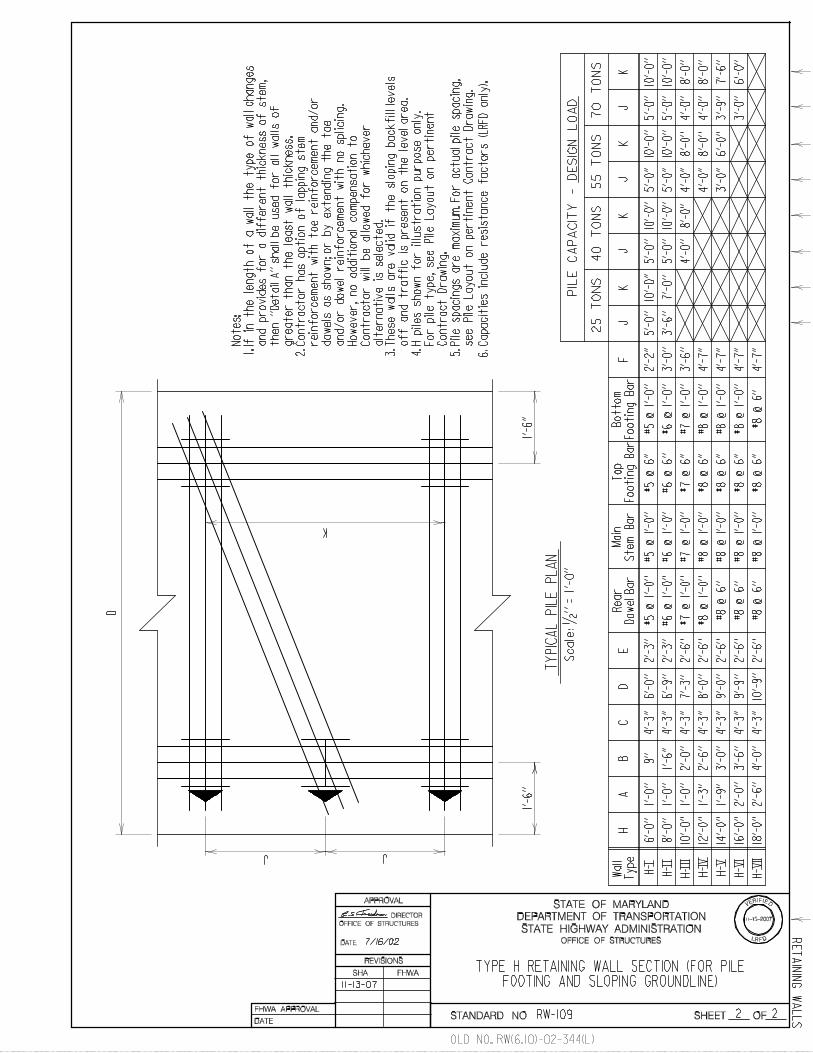
TYPE H RETAINING WALL SECTION (FOR PILEFOOTING AND SLOPING GROUNDLINE)
Rear
Do
wel
Bar
A
Dow
el b
ar**
Fro
nt
Rear
face p
lum
b, to
be d
am
ppro
ofe
d
fro
m t
op o
f fo
oti
ng u
p t
o f
inis
hed
gro
un
dli
ne.
*
Where
specif
ic f
ooti
ng c
oncre
te
an
d s
tem
co
ncre
te i
tem
s a
re i
nclu
ded
in t
he P
rop
osal
fo
r a p
art
icu
lar
wall
, th
ese s
hall
b
e t
he p
ay
lim
its.
Wh
ere
no
sp
ecif
ic i
tem
s h
av
e b
een
set
up
in
th
e P
rop
osal,
th
e c
ost
of
wall
shall
be i
nclu
ded i
n t
he
main
str
uctu
re C
ontr
act
pri
ce, i.
e.;
box c
ulv
ert
, (w
here
win
gs a
re
inclu
ded
in
bo
x c
ulv
ert
ite
m),
;
reta
inin
g w
all
, (w
here
no s
epara
te
pay i
tem
s a
re e
sta
bli
shed),
etc
.
7-16-02
11-13-2007
LR D
VERIFIED
F
11-13-07
OFFICE OF STRUCTURES
DIRECTOR
OFFICE OF STRUCTURES
**
#4
@ 1
’-6
’’ c
/c f
or
wall
ty
pes
H-
I t
hru
H-
III
#4 @
1’-
0’’
c/c
for
wall
types
H-
IV a
nd H
- V
#5 @
1’-
0’’
c/c
for
wal
l ty
pes
H-
VI
an
d H
- V
II
OLD NO. RW(6.10)-02-344(L)
RW-109
For
Dra
inage S
yst
em
, S
ee R
W-3
01
or
SU
B-D
R-2
03
2 2
RE
TA
ININ
G W
AL
LS
DATE:
STATE HIGHWAY ADMINISTRATION
DEPARTMENT OF TRANSPORTATION
STATE OF MARYLAND
STANDARD NO. SHEET OF
SHA FHWA
REVISIONS
APPROVAL
FHWA APPROVAL
DATE:
Wal
l
Ty
pe
HA
BC
DE
FJ
KK
JK
JK
40
TO
NS
25
TO
NS
55
TO
NS
70
TO
NS
Rear
Dow
el B
ar
Top
Fo
oti
ng
Bar
J
6’-0
’’
8’-0
’’
10’-
0’’
12’-
0’’
14’-
0’’
16’-
0’’
18’-
0’’
1’-0
’’
1’-0
’’
1’-0
’’
1’-3
’’
1’-9
’’
2’-0
’’
2’-6
’’
1’-6
’’
2’-0
’’
2’-6
’’
3’-0
’’
3’-6
’’
4’-0
’’
4’-3
’’
4’-3
’’
4’-3
’’
4’-3
’’
4’-3
’’
4’-3
’’
4’-3
’’
6’-0
’’
6’-9
’’
7’-3
’’
8’-0
’’
9’-0
’’
2’-3
’’
2’-3
’’
2’-6
’’
2’-6
’’
2’-6
’’
2’-6
’’
2’-6
’’
#8
@ 6
’’
#8
@ 6
’’
#8
@ 6
’’
#5
@ 1
’-0
’’
#6 @
1’-
0’’
#7
@ 1
’-0
’’
#8
@ 1
’-0
’’
#8
@ 1
’-0
’’
2’-2
’’
3’-0
’’
3’-6
’’
4’-7
’’
4’-7
’’
4’-7
’’
4’-7
’’
5’-0
’’10
’-0’
’
Note
s:
Co
ntr
acto
r h
as o
pti
on
of
lap
pin
g s
tem
If i
n t
he l
en
gth
of
a w
all
th
e t
yp
e o
f w
all
ch
an
ges
and p
rovid
es f
or
a d
iffe
rent
thic
kness o
f ste
m,
gre
ate
r th
an t
he l
east
wall
th
ickness.
rein
forc
em
ent
wit
h t
oe r
ein
forc
em
ent
and/o
r
do
wels
as s
ho
wn
; o
r b
y e
xte
nd
ing
th
e t
oe
an
d/o
r d
ow
el
rein
forc
em
en
t w
ith
no
sp
licin
g.
alt
ern
ati
ve i
s s
ele
cte
d.
1.
2.
K
JJ
Sca
le:
1/2
’’
= 1
’-0
’’
TY
PIC
AL
PIL
E P
LA
N
3.
1’-6
’’1’
-6’’
D
10’-
9’’
#5
@ 1
’-0
’’
#6 @
1’-
0’’
#7
@ 1
’-0
’’
#8
@ 1
’-0
’’
Mai
n
Ste
m B
ar
#5
@ 1
’-0
’’
#6 @
1’-
0’’
#7
@ 1
’-0
’’
#8
@ 1
’-0
’’
#8
@ 1
’-0
’’
#8
@ 1
’-0
’’
#8
@ 1
’-0
’’
Bo
tto
m
Fo
oti
ng
Bar
TYPE H RETAINING WALL SECTION (FOR PILEFOOTING AND SLOPING GROUNDLINE)
9’’
9’-9
’’
PIL
E C
AP
AC
ITY
- D
ES
IGN
LO
AD
#8
@ 1
’-0
’’
5’-0
’’5’
-0’’
5’-0
’’10
’-0’
’10
’-0’
’10
’-0’
’
5’-0
’’10
’-0’
’10
’-0’
’10
’-0’
’5’
-0’’
5’-0
’’
H-I
H-I
I
H-11
1
H-I
V
H-V
H-V
I
H-V
II
#5 @
6’’
#6
@ 6
’’
#7 @
6’’
#8 @
6’’
#8 @
6’’
#8 @
6’’
#8 @
6’’
#8 @
6’’
These w
all
s a
re v
ali
d i
f th
e s
lopin
g b
ackfi
ll l
evels
4. H
pil
es s
ho
wn
fo
r il
lustr
ati
on
pu
rpo
se o
nly
.
Co
ntr
act
Dra
win
g.
For
pil
e t
ype, see P
ile L
ayout
on p
ert
inent
5. P
ile s
pacin
gs
are
maxim
um
. F
or
actu
al
pil
e s
pacin
g,
see P
ile L
ay
ou
t o
n p
ert
inen
t C
on
tract
Dra
win
g.
off
an
d t
raff
ic i
s p
resen
t o
n t
he l
ev
el
are
a.
How
ever,
no a
ddit
ional
com
pensa
tion t
o
Contr
acto
r w
ill
be a
llow
ed f
or
whic
hever
7/16/02
then
’’D
eta
il A
’’ s
hall
be u
sed
fo
r all
w
all
s o
f
11-13-07
11-13-2007
LR D
VERIFIED
F
3’-6
’’7’
-0’’
4’-0
’’8’
-0’’
4’-0
’’8’
-0’’
4’-0
’’8’
-0’’
4’-0
’’8’
-0’’
4’-0
’’8’
-0’’
3’-0
’’6’
-0’’
3’-9
’’7’
-6’’
3’-0
’’6’
-0’’
Cap
acit
ies i
nclu
de r
esis
tan
ce f
acto
rs (
LR
FD
on
ly).
6.
OFFICE OF STRUCTURES
DIRECTOR
OFFICE OF STRUCTURES
OLD NO. RW(6.10)-02-344(L)
RW-109

1 2
DATE:
STATE HIGHWAY ADMINISTRATION
DEPARTMENT OF TRANSPORTATION
STATE OF MARYLAND
STANDARD NO. SHEET OF
SHA FHWA
REVISIONS
APPROVAL
FHWA APPROVAL
DATE:
c Brg.
Scale: 1/4 ’’ = 1’-0’’
Scale: 1/4 ’’ = 1’-0’’
RE
TA
ININ
G W
AL
LS
STANDARD RETAINING WALLSTANDARD DETAILS
SKEWED ABUTMENT
c Brg.
90^ ABUTMENT
Reta
inin
g W
all
Reta
inin
g W
all
Abutment Footing
Wing Wall Footing Wing Wall Footing
Reta
inin
g W
all
Reta
inin
g W
all
Wing Wall Footing
Wing Wall Footing
GUIDE FOR ABUTMENT AND WING WALL FOOTING INTERSECTION
Abutment Footing
6’’
6’’
Sta
nd
ard
Sta
nd
ard
Sta
ndard
Sta
ndard
Std
. R
eta
inin
g W
all
Ste
m
Std
. R
eta
inin
g
Wall
Ste
m
Std
. R
eta
inin
g W
all
Ste
m
Std
. R
eta
inin
g W
all
Ste
m
Exp. Joint Exp. Joint
Exp. Joint
Exp. Joint
Note:For additional details of expansion
7/16/02
DIRECTOR
OFFICE OF STRUCTURES
OFFICE OF STRUCTURES
OLD NO. RW(6.11)-02-345
RW-201
* FOR OFFICE USE ONLY *
joint refer to SUB-WW-101
* GUIDE SHEET FOR PLAN DEVELOPMENT ONLY - DO NOT INCLUDE THIS SHEET IN CONTRACT PLANS *

2 2
DATE:
STATE HIGHWAY ADMINISTRATION
DEPARTMENT OF TRANSPORTATION
STATE OF MARYLAND
STANDARD NO. SHEET OF
SHA FHWA
REVISIONS
APPROVAL
FHWA APPROVAL
DATE:
RE
TA
ININ
G W
AL
LS
STANDARD RETAINING WALLSTANDARD DETAILS
GUIDE FOR WALLS WITH AESTHETIC SURFACE TREATMENT
Scale: 3/8 ’’ = 1’-0’’
Scale: 3/8 ’’ = 1’-0’’
2’’cl.
2’’cl.
2’’cl.
Finished Roadway
1’-1
1’’
3’’
3’’
1’-0’’
Normal Wall Reinforcement
6 - #5 Bars Spaced As Shown
*
2’’cl.
Normal Wall Reinforcement
2’’cl.
2’’ Surface
A = Normal Stem Thickness,
2 1/2 ’’cl. to 3’-11’’ Dowel
See appropriate StandardRetaining Wall sheet
GUIDE FOR PARAPET ATTACHMENT FOR WALLS WITH 1’-0’’ STEM THICKNESS
A
Treatment
Thickness may vary depending ontype of surface treatment used.
*
6 1/4 ’’*
2’-2
’’*
*
Parapet shown for illustration
purpose only. These dimensions
may change depending on type
of parapet used.
*
#5 Epoxy Coated Dowels 3’-11’’ long
See End Post Details for spacing
as well as steel pattern to be utilized
in barrier.
*
7/16/02 OFFICE OF STRUCUTRES
DIRECTOR
OFFICE OF STRUCTURES
OLD NO. RW(6.11)-02-345
RW-201
* FOR OFFICE USE ONLY *
* GUIDE SHEET FOR PLAN DEVELOPMENT ONLY - DO NOT INCLUDE THIS SHEET IN CONTRACT PLANS *

1 1
Finished Groundline
Dampproof
Gutter LineSidewalk Area
-
Finished GroundlineFinished Groundline
Top of proposed sidewalk.
Provide joint in sidewalk
over PVC pipe
4’’ PVC pipe. Slope pipe 2% + to outlet.
Invert at outlet to be 2’’ above gutter line.
(15’ Maximum Spacing)
System I or I I as
dictated by below
If wall has concrete flume
at rear face carry Porous
Backfill to underside of flumeIf front face of wall is visible to
pipe shall extend 3’’ from face of
wall; for sidewalks adjacent to
wall see above; for all other
conditions make flush.
2 cu. ft. Porous Backfill
at each drain
Dampproof
1’-
0’’
Finished
1’-
0’’
This system shall be used for all retaining walls, all
This system shall be used for all box culvert wing walls
less than 16’ high (height of wall from bottom of footing totop of highest section). One drain shall be placed at L of wall
for all walls less than 15’ long. For walls between 15’ and 30’ long,
two drains shall be placed, one at each third point.
9’’
Dampproof
1’-0’’
Porous Backfill
6’’ perforated PVC Drain Pipe
sloped to drain to each outlet
pipe (minimum slope 1/4 ’’/ft.)
2’-0’’
1’-4’’
Concrete (Mix No. 1 or better)
Slope rear face as steep as
ground will allow.
DRAIN AT SIDEWALK
Scale : None
c
Scale : None
Scale : None
SYSTEM II
SYSTEM I
Note:
Exact elevation of drain to be determined1.
2.
6’’ Non-Perforated PVC Circular Pipe
Underdrain Outlet with T-Connection to
6’’ Pipe Underdrain (15’ Maximum
Spacing, 1’’ Fall).
vehicular or pedestrian traffic, drain
and other wing walls that are both less than 30’ long and
#5 @ 1’-6’’ c/c
#5’s spaced as shown
2-#5 bars 1’-6’’ long#5 @ 1’-6’’ c/c
#5’s spaced as shown
2/25/80
6-20-80
*
**
*#5 Threaded Rebar Dowel
Coupler at 1’-6’’ c/c.
DATE:
STATE HIGHWAY ADMINISTRATION
DEPARTMENT OF TRANSPORTATION
STATE OF MARYLAND
STANDARD NO. SHEET OF
SHA FHWA
REVISIONS
APPROVAL
FHWA APPROVAL
DATE:
RE
TA
ININ
G W
AL
LS
RETAINING WALL AND WING WALL
DRAINAGE SYSTEMS
wing walls (not in System I).
11-17-97
2-#5 @ 1’-6’’ c/c
1’-4’’
2’ square concrete
block at each drain,
see System II
for additional details
1’-4’’
4-22-98
1-22-01
3.
1:6 slope to drain to wall
6’’ PVC
Drain Pipe
Groundline
Finished
Groundline
12-14-98
OFFICE OF STRUCTURES
DIRECTOR
OFFICE OF STRUCUTRES
OLD NO. RW(0.01)-80-100
RW-301
by Engineer in field.
Porous backfill (refer to Section 469).
Use this standard for bridges with wing
walls that are not parallel to the highway.
For bridges with wing walls parallel to the
highway see Std. No. SUB-DR-203
sheet 5 of 5 for details.

1 1
RE
TA
ININ
G W
AL
LS5-3-84
4/19/84
CONCRETE RETAINING WALL
CONTRACTION AND EXPANSION JOINTS
Joint locations shall be as shown on contract drawing. If
no locations are given concrete retaining walls shall have
contraction joints a maximum of every 30’-0’’; and expansion
Stop key 9’’ below top of wall.
Reinforcing steel shall not pass through
contraction or expansion joint.
For battered walls, with stems greater
than 12 feet height, key dimensions
noted thus , shall be based on wall
thickness at mid height.*
All keys are nominal size.
Notes:
Only place contraction and expansion
joints in stems (no joint in footer).
1.
2.
3.
4.
5.
6.
W = Width at top of wall.
* *W/3 W/3 W/3
W = Width at top of wall.
* *W/3 W/3 W/3
W/6
W/6
1’’
1’’
No chamfer required on
non-exposed face.
Single layer of tarpaper, full
height of key. Fasten to concrete
with asphaltic cement.
**
Exposed face to have
**
Exposed face to have
3/4 ’’ x 3/4 ’’ chamfer.
3/4 ’’ x 3/4 ’’ chamfer.
Be sure last vertical bar is
placed at this location for
segment with recessed key.
**
1/2 ’’ 1/2 ’’No chamfer required on
non-exposed face.
Dampproof one side
full height of key.
This dimension will vary on
battered walls.*
STEM EXPANSION JOINT
SECTION
SECTION
STEM CONTRACTION JOINT
DATE:
STATE HIGHWAY ADMINISTRATION
DEPARTMENT OF TRANSPORTATION
STATE OF MARYLAND
STANDARD NO. SHEET OF
SHA FHWA
REVISIONS
APPROVAL
FHWA APPROVAL
DATE:
2’’ cl. typ.
2’’ cl. typ.
a maximum of every 90’-0’’
1-4-94
1’’ Sponge type joint material full
height of wall. Fasten to one
face with copper nails.
(See note 1, below).
7-16-02
joints, with 1’’ sponge type material (see 911.02),
3-22-06
5-4-06
Scale: 1 1/2 ’’ =1’-0’’
Scale: 1 1/2 ’’ =1’-0’’
OFFICE OF STRUCTURES
DIRECTOR
OFFICE OF STRUCTURES
OLD NO. RW(6.13)-83-157
RW-401

Bend these bars and
extend to bottom of
lower footer.
Normal reinforcing steel
Top and bottom (Typ.).
Slope as steep as
ground will allow.
Additional #5 bars.
If no bottom layer is called for, then
additional #5 bars bent thus
If bottom mat is called for, bend upper
layer of bottom mat and extend upward
as shown.
5’-0’’
1’-6’’
1’-0’’ For footings under 2’-0’’ thick.
Notes:
All keys are nominal size.1.
KEY SIZES
T Key
TYPICAL SECTION
1 1
RE
TA
ININ
G W
AL
LS
11/4/83
12-9-83
5’-
0’’
Maxim
um
STEPPED FOOTING DETAIL
DATE:
STATE HIGHWAY ADMINISTRATION
DEPARTMENT OF TRANSPORTATION
STATE OF MARYLAND
STANDARD NO. SHEET OF
SHA FHWA
REVISIONS
APPROVAL
FHWA APPROVAL
DATE:
For footings 2’-0’’ thick and over.
’’T
’’
’’T
’’
Maximum vertical spacing is
1’-0’’ for additional bars.
2’’ x 4’’
3’’ x 6’’
4’’ x 8’’
5’’ x 10’’
1’-0’’ to 1’-5’’
1’-6’’ to 1’-11’’
2’-0’’ to 2’-5’’
2’-6’’ to 3’-0’’
7-18-94
Optional construction joint with
key (Typ.) (one construction joint
required). For key size see chart.
Scale: 3/8 ’’=1’-0’’
9-24-96
8-28-02
DIRECTOR
shall be provided @ 1’-0’’. #5 bars @ 1’-0’’
shall also be provided perpendicular to
these bars for the 5’-0’’ length.
7-16-02
OFFICE OF STRUCTURES
OFFICE OF STRUCTURES
OLD NO. RW(6.12)-83-155
RW-402

RE
TA
ININ
G W
AL
LS
5’-
0’’
Maxim
um
1 1
1.
KEY SIZES
T Key
TYPICAL SECTION
1’-6’’ 1’-6’’
Slope as steep as
ground will allow.
Bend these bars and
extend to bottom of
lower footer.
Normal reinforcing steel
Top and bottom (Typ.).
Bend these bars and
extend to top of
upper footer.
2.
3-#6 bars each way
over piles (typ.).
Additional #5 bars
(maximum vertical
Optional
1’-
0’’
1’-
0’’
*
*To center line of pile
and to end of lower footer.
3’’ cl. typ.
Steel H piles shown. Other pile types
similar.
Notes:
See Plan of Footing for orientation
of piles.
STEPPED FOOTING DETAIL WITH PILES
5/16/89
6-8-90
DATE:
STATE HIGHWAY ADMINISTRATION
DEPARTMENT OF TRANSPORTATION
STATE OF MARYLAND
STANDARD NO. SHEET OF
SHA FHWA
REVISIONS
APPROVAL
FHWA APPROVAL
DATE:
7-2-93
Minimum step length = 10’-0’’
2’’ cl. typ.
spacing of 1’-0’’).
’’T
’’
3’’ cl.
typ.
Scale: 3/8 ’’ = 1’-0’’
4’’ x 8’’
5’’ x 10’’
2’-0’’ to 2’-5’’
2’-6’’ to 3’-0’’
construction
joint with key
(Typ.) (one
construction
joint required).
For key size see
chart.
7-18-94
9-24-96
7-16-02
OFFICE OF STRUCTURES
DIRECTOR
OFFICE OF STRUCTURES
OLD NO. RW(6.14)-89-201
RW-403

6-8-9012-4-84
Note:
ELEVATION
1 1
7/26/79
12-12-79
REINFORCEMENT ADJUSTMENTAT UTILITY AND/OR PIPE OPENING IN WALL
Increase the size of each of the first
three normal main vertical reinforcing steel
bars, on each side of the wall opening.
New bar size shall be such that each
the total area of the main reinforcing steel
that has been cut.
When pipe size is over 3’-0’’, sufficient
horizontal bars shall be addded over and
below opening to transfer load to adjacent
full sections of wall.
In no case shall concrete cover be less
than 2’’.
1.
2.
3.
Normal Vertical Main
Reinforcing Steel for Wall.
#5 bars, each
face (Typical).
Utility
and
/or
Pipe O
peni
ng
6’’Typ
.
2’’ min. cl. (Typ.)
Normal Horizontal
Reinforcing Steel.These bars to have area increased.
Scale: None
DATE:
STATE HIGHWAY ADMINISTRATION
DEPARTMENT OF TRANSPORTATION
STATE OF MARYLAND
STANDARD NO. SHEET OF
SHA FHWA
REVISIONS
APPROVAL
FHWA APPROVAL
DATE:
increase in bar area shall at least equal /16
7-2-93
Adjust adjacent vertical & horizontal
steel pattern so that nearest bars to
opening are placed at minimum distances.
(This also applies to front face of wall).
OFFICE OF STRUCTURES
DIRECTOR
OFFICE OF STRUCTURES
RE
TA
ININ
G W
AL
LS
OLD NO. M(6.03)-79-77
RW-501
* FOR OFFICE USE ONLY *
* GUIDE SHEET FOR PLAN DEVELOPMENT ONLY - DO NOT INCLUDE THIS SHEET IN CONTRACT PLANS *