Embed Size (px)
Citation preview
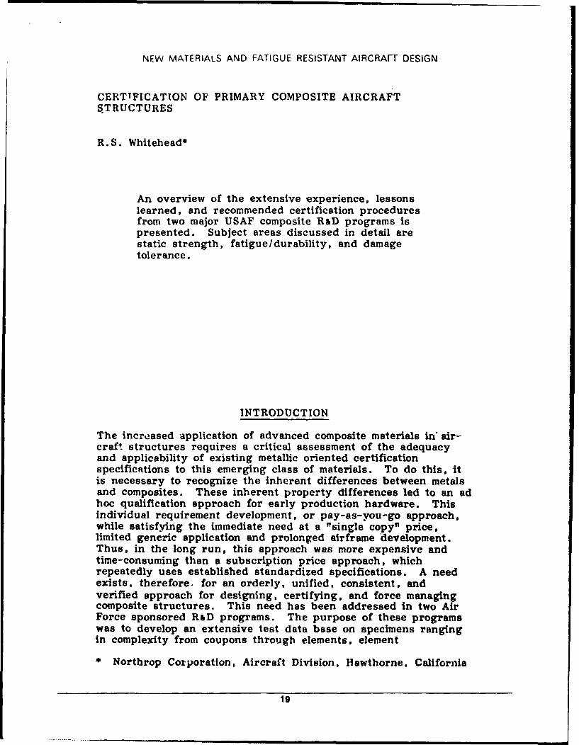
O ONRL Report 017-R
IN
o0
S D TIC Workshop Proceedings on CompositeS ELECT E Aircraft Certification and Airworthiness
JUN 2 2 1989
D Dennis R. Sadowski
6 October 1988
Approved for public release; distribution unlimited
U.S. Office of Naval Research, London
89 6 20 192
UNCLASSIFIEDSECURITY CLASSIFICATION OF THIS PAGE
REPORT DOCUMENTATION PAGE!a REPORT SECURITY CLASSIFICATION lb RESTRICTIVE MARKINGS
UNCLASSIFIED2a SECURITY CLASSIFICATION AUTHORITY 3 DISTRIBUTION/AVAILABILITY OF REPORT
Approved for public release;2b DECLASSIFICATION /DOWNGRADING SCHEDULE distribution unfitited
4. PERFORMING ORGANIZATION REPORT NUMBER(S) 5. MONITORING ORGANIZATION REPORT NUMBER(S)
8-017-R
6a. NAME OF PERFORMING ORGANIZATION 6b. OFFICE SYMBOL 7a. NAME OF MONITORING ORGANIZATIONOffice of Naval Research (If applicable)Branch Office, London NRBRO
6c. ADDRESS (City, State, and ZIP Code) 7b. ADDRESS (City, State, and ZIP Code)
Box 39FPO, NY 09510-0700
8a. NAME OF FUNDING/SPONSORING l8b. OFFICE SYMBOL 9. PROCUREMENT INSTRUMENT IDENTIFICATION NUMBERORGANIZATION (If applicable)
8c. ADDRESS (City, State, and ZIP Code) 10. SOURCE OF FUNDING NUMBERS
PROGRAM IPROJECT ITASK IWORK UNITELEMENT NO. NO NO ACCESSION NO.
1 TITLE (include Security Classification)
Workshop Proceedings on Composite Aircraft Certification and Airworthiness
12 PERSONAL AUTHOR(S)Dennis R. Sadowski
13a. TYPE OF REPORT 113b TIME COVERED j14. DATE OF REPORT (Year, Month, Day) 115 PAGE COUNTTechnical FROM TO 6 October 19887
16. SUPPLEMENTARY NOTATION
17. COSATI CODES - SUBJECT TERM, ntipuo, r $ sin c ssary and identify by block number)
FIELD GROUP SUB-GROUP l01 03 atenals_ *furft Airworthiness ructures..
omi s Fiber Plasti/ Aircraft Certification. -
19. ABSTRACT (Continue on reverse if necessary and identify by block number)
" This report contains a summary of the workshop, a list of attendees, a prepaper entitled "Some Areas for Discus-
sion Suggested by RAE," and the presentations on mposite Aircraft Structures, Civil Aviation Concerns, Impact Dam-age, RAE Composite Certification, and the Effect of served Climatic Conditions on the Moisture Equilibrium Level ofFibre-Reinforced Plastics. r(. tI-( , ,
20 DISTRIBUTION/AVAILABILITY OF ABSTRACT 21. ABSTRACT SECURITY CLASSIFICATION
0 UNCLASSIFIED/UNLIMITED 0 SAME AS RPT. 0 DTIC USERS UNCLASSIFIED22a NAME OF RESPONSIBLE INDIVIDUAL 22b TELEPHONE (Include Area Code) 22c OFFICE SYMBOL
C.J. Fox (44-1) 409-43 4 310DO FORM 1473, 84 MAR 83 APR edition may be used until exhausted SECURITY CLASSIFICATION O THIS PAGE
All other editions are obsolete * ...O . G O vfUC T p P rin tu n q O PS Si e : j111 - 0 7 0 4 4
UJNCI ASSIFIED
Contents
Foreword . . . . . . . . . . . . . . . . . . . . . . . . . . . . . . . . . . . . . . . . . . . . 1
W orkshop Summary ...................................... 1
List of Attendees ....... ....................................... 2
Prepaper: Some areas for Discussion Suggested by RAE .................... 5
Opening Remarks ............................ Mr. Tom Hess ..... .11
Composite Aircraft Certification ................... Mr. K.B. Sanger . . . . 13
Certification of Primary Composite Aircraft Structures . . . Mr. R.S Whitehead . . 19
Civil Aviation Concerns ........................ Dr. John Bristow . . . . 53
Impact Damge .......................... Professor G. Davies . .59
RAE Composite Certification ................... Dr. A.W. Cardrick . . . 63
The Effect of Observed Climatic Conditions
on the Moisture Equilibrium Level of Fibre-Reinforced Plastics ...................... T.A. Collings ...... 69
Accesion For
NTIS CRA&IDTIC TAOUnannouncedJustification
Distribution I
Availability Codes
Avail ancd/or
Dist Special
Workshop Proceedings on CompositeAircraft Certification and Airworthiness
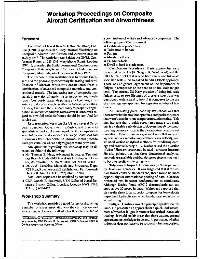
Foreword a combination of metals and advanced composites. Thefollowing topics were discussed:
The Office of Naval Research Branch Office, Lon- * Certification proceduresdon (ONRL) sponsored a 1-day informal Workshop on e Tolerance to impactComposite Aircraft Certification and Airworthiness on * Fatigue16 July 1987. The workshop was held at the ONRL Con- * Moisture effectsference Room at 223 Old Marylebone Road, London * Failure criteriaNW1. It preceded the Sixth International Conference on * Dwell at load in static tests.Composite Materials/Second European Conference on Certification Procedures. Basic approaches wereComposite Materials, which began on 20 July 1987. presented by the US (K. Sanger, R. Whitehead) and the
The purpose of this workshop was to discuss the is- UK (A. Cardrick) that rely on both small- and full-scalesues and the philosophy concerning the testing and certi- specimen tests- the so-called building block approach.fication of aircraft structures constructed from a There was no general agreement on the importance ofcombination of advanced composite materials and con- fatigue to composites or the need to do full-scale fatigueventional metals. The increasing use of composite ma- tests. The current US Navy practice of doing full-scaleterials in new aircraft made this an important and timely fatigue tests to two lifetimes of a severe spectrum wastopic. Composite materials possess excellent fatigue re- questioned with regard to how that compares to the usesistance but considerable scatter in fatigue properties. of an average use spectrum for a greater number of life-This together with their susceptibility to property degra- times.dation in hot/wet conditions raises several issues with re- An interesting point made by Whitehead was thatgard to how full-scale airframes should be certified for there never has been a "hot-spot" in a composite structureservice use. that wasn't seen in room-temperature static testing. This
Representation was from the US and several Euro- may indicate that a quick room-temperature dry staticpean countries. Government, industry, and university test is a valuable early design tool, even though the struc-specialists attended. A summary of the workshop discus- ture may be more critical in the elevated-temperature wetsions follows in this document. The six presentations and condition. Other opinions expressed were that we needdiscussions were intended to be informal. Notes precede agreement on a realistic impact threat (low velocity) andeach presentation where only vugraphs were provided, we need verfied analytical methods for predicting dam-
Any questions regarding this workshop may be di- age and residual strength. G. Davies raised the questionrected to either of the following: of what failure criteria should be used - stress or fracture." Mr. Thomas E. Hess, Advanced Structures Technol- He also pointed out that three-dimensional analytical
ogy Branch, Code 6043, Naval Air Development Cen- methods are available and that design engineers may needter, Warminster, PA 18974-5000, Tel: 215-441-1463 to become proficient in using them.
" Dr. A.W. Cardrick, Materials and Structures Dept, Tolerance to Impact. Discussions on this topic wereX32 Bldg, Royal Aircraft Establishment, Farnborough by Davies and Cardrick. It was suggested that if the im-Hants GU14 6TD, Tel: (0252) 24461 X5026 pact threat could be standardized, there would be more
Additional copies can be obtained by contacting: opportunity for international pooling of data. Cardrick* CDR Dennis R. Sadowski, USN Office of Naval Re- presented two impactor configurations as candidates.
search Branch Office, London, London NW1 5TH, Although Davies found APC-2 thermoplastic not tooTel: (01) 409-4413. good above 20-m/sec impacts, Whitehead reported that
his results show it far superior to epoxy for low-velocityWorkshop Summary impact and hydraulic ram - i.e., less damage and more re-
sidual strength.This workshop provided a good forum for discussing Fatigue. Cardrick was the principle speaker on this
a number of issues associated with the certification and issue. He presented an approach for a quick-look assess-airworthiness of new aircraft which will be constructed of ment of whether fatigue is more or less critical than static
Coordination for this report, introduction/summary, and introduc- loading. It would be fair to say that there was not general
tory notes by CDR Dennis R. Sadowski. CDR Sadowski, USN, is agreement on the fatigue issue and, in particular, whetherONRL's Aerospace Systems Officer. it does or does not have to be a concern for composites.
I

Moisture. This issue was discussed by T. Collings. Herr Dr. A. HabelThis is another issue for which there is not universal BWB-ML 2-51agreement on criteria or worst-case environment. It is, West Germanyhowever, a definite concern in the design process.
Failure Criteria. Mr. R. Potter, who addressed this Mr. Allen Halltopic, said that we need better failure criteria - an obser- Westland Helicoptersvation affirmed by Hess, who pointed out that we need a UKbetter definition of failure. Potter asked whether anyonehas ever predicted a failure location, failure mode, and LTC J. Hansenfailure load. EOARD
Dwell at Load In Static Tests. Dr. Cardrick spoke on USthis issue. The concern is what happens when loads areheld for a matter of minutes. Indications are that strains Dr. W. T. Hartaren't affected, but, the question is, what happens for National Aerospace Laboratorystructures which are in a degraded condition? The Netherlands
List of Attendees Mr. Thomas HessNaval Air Development Center
Dr. John Bristow USCivil Aviation AuthorityUK Dr. Lars Jarfall
SAAB-Scania AircraftMr. R. Cansdale SwedenRoyal Aircraft EstablishmentUK Dr. David James
Civil Aviation AuthorityDr. A. Cardrick UKRoyal Aircraft EstablishmentUK Mr. R. Kite
Royal Aircraft EstablishmentMr. T. Collings UKRoyal Aircraft EstablishmentUK Mr. C. Luffman
Airship IndustriesProfessor Glyn Davies UKImperial CollegeUK Dr. J. Moon
Royal Aircraft EstablishmentMr. J.B. DeJong UKNational Aerospace LaboratoryThe Netherlands Wg Cdr P. Perry
Royal Air ForceDr. E. Demuts UKAir Force Aeronautical LabUS Mr. R. Potter
Royal Aircraft EstablishmentSqn Ldr C.A. Elkins UKRoyal Air ForceUK Mr. C. Robinson
British AerospaceMr. J. Fray UKBritish AerospaceUK Commander Dennis Sadowski
Office of Naval ResearchHerr Ambrose Goilner USIABG-TFSWest Germany
2
Mr. Michael Sancho Mr. J. StottService Technique Des Programmes Aeronautiques Airship IndustriesFrance UK
Mr. K. Sanger Mr. WestwoodMcDonnell Aircraft Co Airship IndustriesUS UK
Mr. Alex Segal Mr. R. WhiteheadIsrael Aircraft Industries Northrop Aircraft CorporationIsrael US
Mr. Kieth Fitz-Simons Dr. N. WilsonWestland Helicopters Royal Aircraft EstablishmentUK UK
Dr. D. StoneRoyal Aircraft EstablishmentUK
3
This page intentionally left blank.
ANNEX A : COMPOSITES AIHWOR'THINESS WORKSHOP
SOME AREAS FOR DISCUSSION SUGGESTED BY RAE
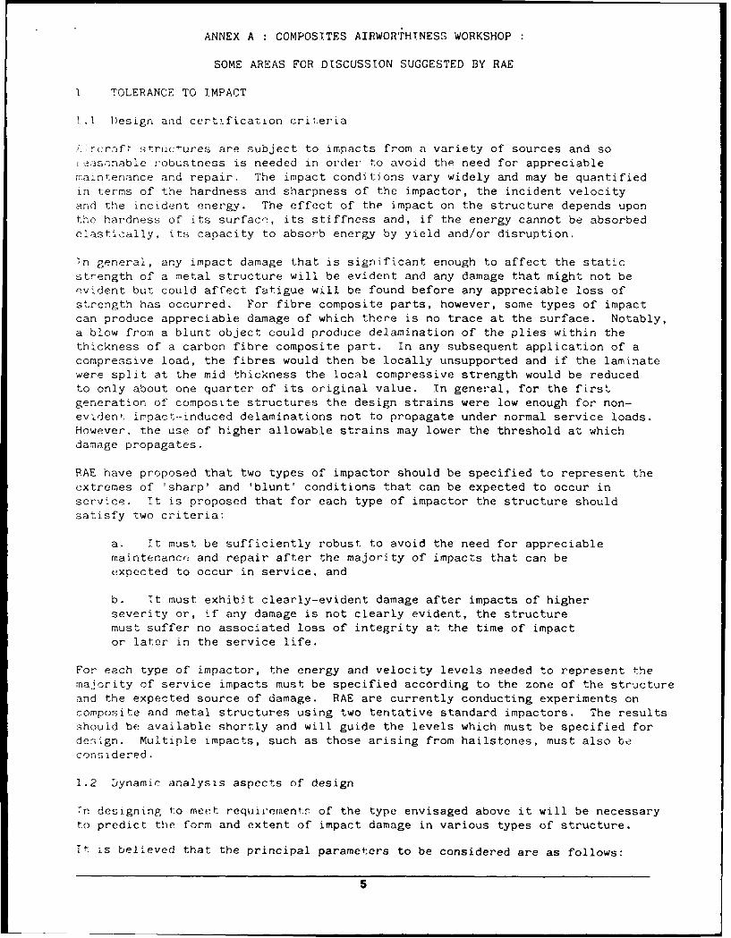
1 TOLERANCE TO IMPACT
. ]Design and certification criteria
; rfl structures are subject to impacts from a variety of sources and soteasnnable robustness is needed in order to avoid the need for appreciablemaintenance and repair. The impact conditions vary widely and may be quantifiedin terms of the hardness and sharpness of the impactor, the incident velocityand the incident energy. The effect of the impact on the structure depends uponthe hardness of its surface, its stiffness and, if the energy cannot be absorbedelastically, its capacity to absorb energy by yield and/or disruption.
Tn general, any impact damage that is significant enough to affect the static
strength of a metal structure will be evident and any damage that might not beevident but could affect fatigue will be found before any appreciable loss ofstrength has occurred. For fibre composite parts, however, some types of impactcan produce appreciable damage of which there is no trace at the surface. Notably,a blow from a blunt object could produce delamination of the plies within thethickness of a carbon fibre composite part. In any subsequent application of acompressive load, the fibres would then be locally unsupported and if the laminatewere split at the mid thickness the local compressive strength would be reducedto only about one quarter of its original value. In general, for the firstgeneration of composite structures the design strains were low enough for non-evident impact--induced delaminations not to propagate under normal service loads.However, the use of higher allowable strains may lower the threshold at whichdamage propagates.
RAE have proposed that two types of impactor should be specified to represent theextremes of 'sharp' and 'blunt' conditions that can be expected to occur inservice. It is proposed that for each type of impactor the structure shouldsatisfy two criteria:
a. It must be sufficiently robust to avoid the need for appreciablemaintenance and repair after the majority of impacts that can beexpected to occur in service, and
b. It must exhibit clearly-evident damage after impacts of higherseverity or, if any damage is not clearly evident, the structuremust suffer no associated loss of integrity at the time of impactor later in the service life.
For each type of impactor, the energy and velocity levels needed to represent themajority of service impacts must be specified according to the zone of the structureand the expected source of damage. RAE are currently conducting experiments oncomposite and metal structures using two tentative standard impactors. The resultsshouid be available shortly and will guide the levels which must be specified fordesign. Multiple impacts, such as those arising from hailstones, must also beconsidered.
1.2 Dynamic analysis aspects of design
Tn designing to meet requirementr of the type envisaged above it will be necessaryto predict the form and extent of impact damage in various types of structure.
It is believed that the principal parameters to be considered are as follows:
5
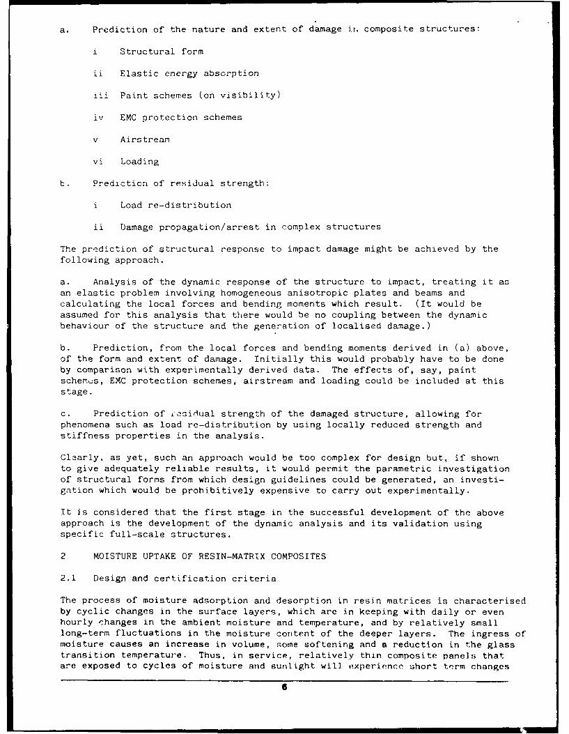
a. Prediction of the nature and extent of damage iT. composite structures:
i Structural form
ii Elastic energy absorption
iii Paint schemes (on visibility)
iv EMC protection schemes
v Airstream
vi Loading
b. Prediction of residual strength:
i Load re-distribution
ii Damage propagation/arrest in complex structures
The prediction of structural response to impact damage might be achieved by thefollowing approach.
a. Analysis of the dynamic response of the structure to impact, treating it asan elastic problem involving homogeneous anisotropic plates and beams andcalculating the local forces and bending moments which result. (It would beassumed for this analysis that there would be no coupling between the dynamicbehaviour of the structure and the generation of localised damage.)
b. Prediction, from the local forces and bending moments derived in (a) above,of the form and extent of damage. Initially this would probably have to be doneby comparison with experimentally derived data. The effects of, say, paintschemus, EMC protection schemes, airstream and loading could be included at thisstage.
c. Prediction of iesi-ual strength of the damaged structure, allowing forphenomena such as load re-distribution by using locally reduced strength andstiffness properties in the analysis.
Clearly, as yet, such an approach would be too complex for design but, if shownto give adequately reliable results, it would permit the parametric investigationof structural forms from which design guidelines could be generated, an investi-gation which would be prohibitively expensive to carry out experimentally.
It is considered that the first stage in the successful development of the aboveapproach is the development of the dynamic analysis and its validation usingspecific full-scale structures.
2 MOISTURE UPTAKE OF RESIN-MATRIX COMPOSITES
2.1 Design and certification criteria
The process of moisture adsorption and desorption in resin matrices is characterisedby cyclic changes in the surface layers, which are in keeping with daily or evenhourly changes in the ambient moisture and temperature, and by relatively smalllong-term fluctuations in the moisture content of the deeper layers. The ingress ofmoisture causes an increase in volume, some softening and a reduction in the glasstransition temperature. Thus, in service, relatively thin composite panels thatare exposed to cycles of moisture and sunlight will experience short term changes
6
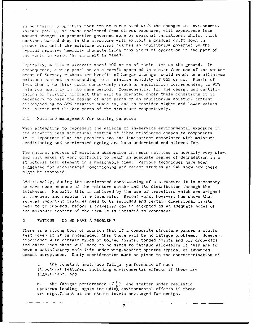
in mec|hinic:il prupe'ties that can be correlated with the changes in environment.Thicker par,els, or those sheltered from direct exposure, will experience lessmarked changes i.n properties governed more by seasonal variations, whilst thicksections buried deep in the structure will exhibit a gradual drift down inproperties until the moisture content reaches an equilibrium governed by the.ypical relative humidity characterising many years of operation in the part ofthe world in which the aircraft is based.
'ypically, r>-Vary aircraft speni 90% or so of their time on the ground. Inconsequence, a wing panel on an aircraft operated in winter from one of the wetterareas of Europe, without the benefit of hangar storage, could reach an equilibirummoisture content corresponding to a relative humidity of 85% or so. Panels of
~ss than i mm thick could conceivahly reach an equilibrium corresponding to 95%rielative humndity in the same period. Consequently, for the design and certifi-cation of military aircraft that will be operated under these conditions it isnecessary to base the design of most parts on an equilibrium moisture contentcorresponding to 85% relative humidity, and to consider higher and lower valuesf-: ;hinner and thicker parts of the structure respectively.
2.2 Moistire management for testing purposes
When attempting to represent the effects of in-service environmental exposure inthe airworthiness structural testing of fibre reinforced composite componentsit is important that the problems and the limitations associated with moistureconditioning and accelerated ageing are both understood and allowed for.
The natural process of moisture absorption in resin matrices is normally very slow,and this makes it very difficult to reach an adequate degree of degradation in astructural test element in a reasonable time. Various techniques have beensuggested for accelerated conditioning and recent studies at RAE show how thesemight be improved.
Additionally, during the accelerated conditioning of a structure it is necessaryto have some measure of the moisture uptake and its distribution through thethickness. Normally this is achieved by the use of travellers which are weighedat frequent and regular time intervals. Recent work, however, has shown thatseveral important features need to be included and certain dimensional limitsneed to be imposed, before a traveller can be accepted as an adequate model of'he moisture content of the item it is intended to represent.
3 FATTGUE - DO WE HAVE A PROBLEM ?
There is a strong body of opinion that if a composite structure passes a statictest (even if it is undegraded) then there will be no fatigue problems. However,experience with certain types of bolted joints, bonded joints and ply drop-offsindicates that these will need to be sized to fatigue allowables if they are tohave a satisfactory safe life under wing-bendin, spectra typical of advancedcombat aeroplanes. Early consideration must be given to the characterisation of
a. the constant amplitude fatigue performance of suchstructural features, including environmental effects if these aresignificant, and
b. the fatigue performance (E 11) and scatter under realisticN
spectrum loading, again including environmental effects if theseare significant at the strain levels envisaged for design.
7
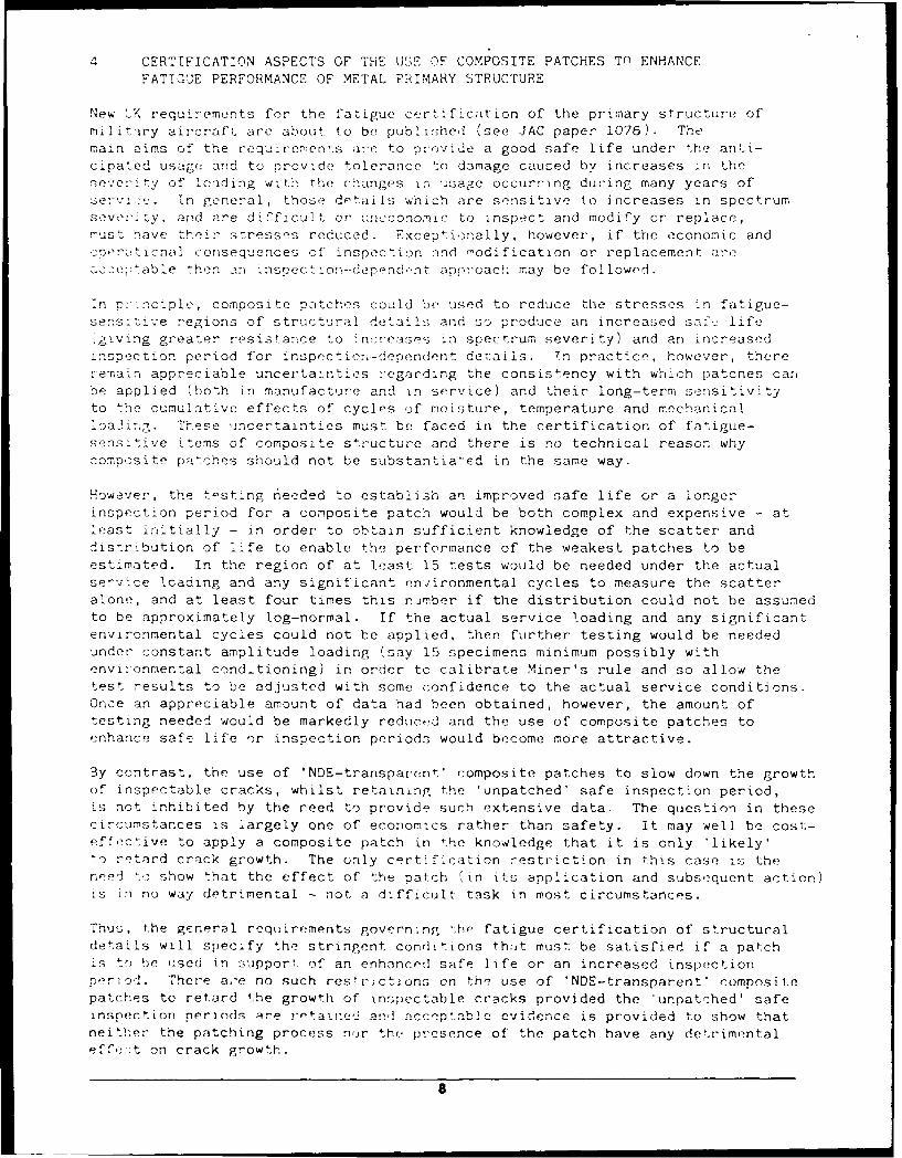
4 CERTIFICATION ASPECTS OF THE USE OF COMPOSITE PATCHES TO ENHANCEFATIGUE PERFORMANCE OF METAL PRIMARY STRUCTURE
New tK requirements for the fatigue certification of the primary structure ofmilitiry aircraft are about to be published (see JAC paper 1076). Themain aims of the requirements are to provide a good safe life under the anti-cipated usage and to provide tolerance to damage caused by increases ;n theseverity of Loading wlth the changes in usage occurring during many years of
in goeneral, those details which are sensitive to increases in spectrumseven' ty, and are difficult or uneconomic to inspect and modify or replace,must nave the ir s:tresses reduced. Except ionally, however, if the economic andcroraticnal consequences of inspection and modification or replacement are-,, -etable t hen an insrection-depend.-nt anpro:oach may be followed.
in p:-nciple, composite patches could he used to reduce the stresses in fatigue-sensitive regions of structural details and so produce an increased saf.j life,giving greater resistance to increases in spectrum severity) and an increasedinspection period for inspection-dependent derails. Tn practice, however, thereremain appreciable uncertainties r'egarding the consistency with which patches car,be applied (both in manufacture and in service) and their long-term sensitivityto the cumulative effects of cycles of moisture, temperature and mechanicalloading. These uncertainties must be faced in the certification of fatigue-sensitive items of composite structure and there is no technical reason whycomposite patches should not be substantia-ed in the same way.
However, the testing needed to establish an improved safe life or a longerinspection period for a composite patch would be both complex and expensive - atleast initially - in order to obtain sufficient knowledge of the scatter anddistribution of life to enable the performance of the weakest patches to beestimated. In the region of at least 15 tests would be needed under the actualservice loading and any significant environmental cycles to measure the scatteralone, and at least four times this nmber if the distribution could not be assumedto be approximately log-normal. If the actual service loading and any significantenvironmental cycles could not be applied, then further testing would be neededunder constant amplitude loading (say 15 specimens minimum possibly withenvironmental cond-tioning) in order to calibrate Miner's rule and so allow thetest results to be adjusted with some confidence to the actual service conditions.Once an appreciable amount of data had been obtained, however, the amount oftesting needed would be markedly reductd and the use of composite patches toenhance safe life or inspection periods would become more attractive.
By contrast, the use of 'NDE-transparent' composite patches to slow down the growthof inspectable cracks, whilst retaining the 'unpatched' safe inspection period,is not inhibited by the reed to provide such extensive data. The question in thesecircumstances is largely one of economics rather than safety. It may well be cost-effective to apply a composite patch in the knowledge that it is only 'likely'to retard crack growth. The only certiflcation restriction in this case is the
reed to show that the effect of the patch (in its application and subsequent action)Is in no way detrimental - not a difficult task in most circumstances.
Thus, the generel requirements governing '.the fatigue certification of structuraldetails will specify the stringent conditions that must be satisfied if a patchis t-) he used in support of an enhanced safe life or an increased inspectionneriod. There are no such restrictions on the use of 'NDE-transparent' compositepatches to retard the growth of inspectable cracks provided the 'unpatched' safeinspection nprinds lre retailec an ceptable cvidceic is provided to show thatneither the patching process nojr the presence of the patch have any detrimentaleffe,-t on crack growth.
8
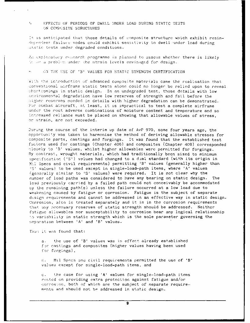
i;.FFECT1 OF PERIODS OF DWELL UNDER LOAD DURING STATIC TESTSON COMPOSITE STRUCTURES
it is anticipated that those details of composite structure which exhibit resin-':eprevdent failut modes could exhibit senci;Ivity to dwell under load duringstatic tests under degraded conditions.
A;: 'xporatOry :,-:;earch programme Ls planned to assess whether there is likelya probic: under he strain levels envisaged for design.
h ON THE USE OF 'B' VALUES FOR STATTC STRENGTH CERTIFICATION
W;'h rhe introduction of advanced composite materials came the realisation thatconventional airframe static tests alone could no longer be relied upon to revealshcrtcomings in static design. In an undegraded test, those details with lowen'ironmental degradation have low reserves of strength and fail before the0igheC- reserves needed in details with higher degradation can be demonstrated.F'cr combat aircraft, at least, it is impractical to test a complete airframeunder the most adverse combinations of moisture content and temperature and soincreased reliance must be placed on showing that allowable values of stress,or strain, are not exceeded.
During the course of the interim up date of AvP 970, some four years ago, theopportunity was taken to harmonise the method of deriving allowable stresses forcomposite parts, castings and forgings. It was found that the established testfactors used for castings (Chapter 406) and composites (Chapter 408) correspondedclosely to 'B' values, whilst higher allowables were permitted for forgings.By contrast, wrought materials, which had traditionally been sized to minimum
specification ('S') values had changed to a dial standard (with its origin inMil Specs and civil requirements) permitting 'B' values (generally higher than'S' values) to be used except in single-load-path items, where 'A' values(generally similar to 'S' values) were required. It is not clear why thenumber of load paths was considered to have any bearing on static design. Theload previously carried by a failed path could not conceivably be accommodatedby the remaining path(s) unless the failure occurred at a low load due toweakening caused by fatigue or corrosion. Fatigue is the subject of separatedesign requirements and cannot be addressed in an effective way in static design.Corrosion, also is treated separately and it is in the corrosion requirementsthat any aecessary reserves of static strength should be addressed. Neitherfatigue allowables nor susceptability to corrosion bear any logical relationshipto variability in static strength which is the sole parameter governing theseparation between 'A' and 'B' values.
Thu'; it was found that:
a. the use of 'B' values was in effect already establishedfor castings and composites (higher values having been used
for forgings)
n. Mil Specs and civil requirements permitted the use of 'B'values except for single-load-path items, and
c. the case for using 'A' values for single-load-path itemsrested on providing extra protection against fatigue and/orcorros;on, both of which are the subject of separate require--ments and should not be addressed in static design.
9
2n c0259qence, , 'B' values were specified in Chapter 200 of Def Stan 00-970
fo' static st-ength certification and io special requirements were made forsingle- A d-path items.
't rust !- said that the much !ar.;er a o C a f testing needed to establish an 'A'
val., o'1!d te penailty in all.)wabl st' os"', Loth mitigate against the use of 'A'
valu,'; for sructural details. To obtain a' 'A' value using order statistics-ank7 v a. ues order is sa,,d to ',qi'-e 296 test- results, whereas just 3G
-f .'I' value over : i-i]llr samples are nermissibile usir'Th, aL-_¢ l or C:>er 20) . Thc pezalty In ;)'lcwable stress for wrought mae,'la!::
.)r,'o- C' 5%, wheoreas r-io,,., o nearer 15% for composites. 1t K;
: th ,t '9' values c:v ar .innaccepta.,le risk of static failure,ii' o f~r. ' u ,, % t. failur at. )0% of !he dCoign
.f""of ,af y .- r"a!l between I :n 1C, aid I in 2QPO0.10ab'ty of he ' qution.
10
Notes on Opening Remarks by Mr. Tom * Test one statically
Hess * Test one to two lifetimes of fatigue.
The traditional certification is questionnablc for"The importance of establishing an approach to cer- composite because:
tification and airworthiness of composite aircraft." * Great tolerance
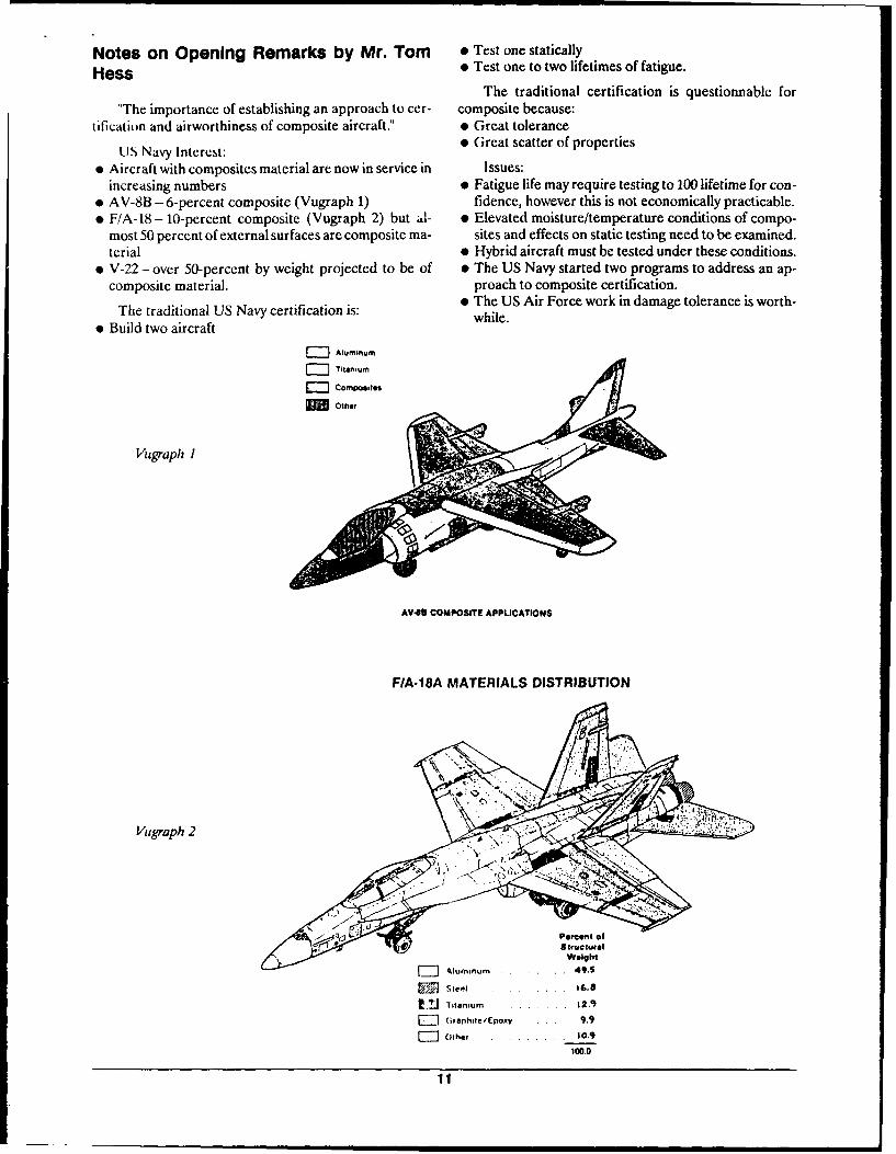
US Navy Interest: 0 Great scatter of properties
* Aircraft with composites material are now in service in Issues:increasing numbers * Fatigue life may require testing to 100 lifetime for con-
t AV-8B - 6-percent composite (Vugraph 1) fidence, however this is not economically practicable." F/A- 18- 10-percent composite (Vugraph 2) but al- * Elevated moisture/temperature conditions of compo-
most 50 percent of external surfaces are composite ma- sites and effects on static testing need to be examined.terial * Hybrid aircraft must be tested under these conditions.
" V-22 - over 50-percent by weight projected to be of # The US Navy started two programs to address an ap-composite material, proach to composite certification.
* The US Air Force work in damage tolerance is worth-The traditional US Navy certification is: while.
* Build two aircraft
7-- Aluminum
E Compo isEM Other
Vugraph I
AV48 COMPOSITE APPLICATIONS
FIA-18A MATERIALS DISTRIBUTION
Mugraph 2
Percent ofStructural
Weight
o,urnnum .... ... 49.S
Ste . . 16.8
V. J Titlanium .. . . 12.0)
(,ranhrte/Epoxy .... 9.9
F ] Other . ..... . 10.9
100.0
11I
This page intentionally left blank.
12
Nctes of presentation on "Composite Air- e The graph of epoxy tension compression strength
craft Certification" by Mr. K.B. Sanger: relative to temperature shows greatest loss under hothumid conditions.
" Mac Air looked at approaches to evaluating static * Composites in use are almost insensitive to fatigue,strength and fatigue based on the Navy program and probably due to stress/strain levels of operation. With
then developed a testing methodology, reference to F/A-18 and AV-8, McDonell Aircraft* The advent of resin matrix composite caused a formal Company is operating around 20-40 ksi gross stress
recognition of the importance and dependence of the which shows significant life-cycles. The main concerncertification procedure on the performance of the cou- is with the evidence of fatigue scatter.
pon design and element design allowables test. Upon e An approach for certification which requires condi-
performance of these tests the contractor tested spe- tioning of the test article is not very practical from an
cimens of larger size and complexity and related these economic standpoint nor to the limits of the programresults back to the design allowables properties. This schedule.
is the general approach used today. An alternative approach for a structure that is pri-* The motive behind the building block approach is to marily composites is to apply a single factor on the load
account for the sensitivity exhibited by composites to to compensative for environment sensitivity. However,the environment, and also to account for large data for a mixed metal and composite this may not be possiblescatter. due to the differences of sensitivity; the McDonell ap-
proach was to correlate measured strength during statictests with environmental allowables properties.
"COMPOSITE AIRCRAFT CERTIFICATION"
K.B. SANGERMCDONNELL AIRCRAFT COMPANY
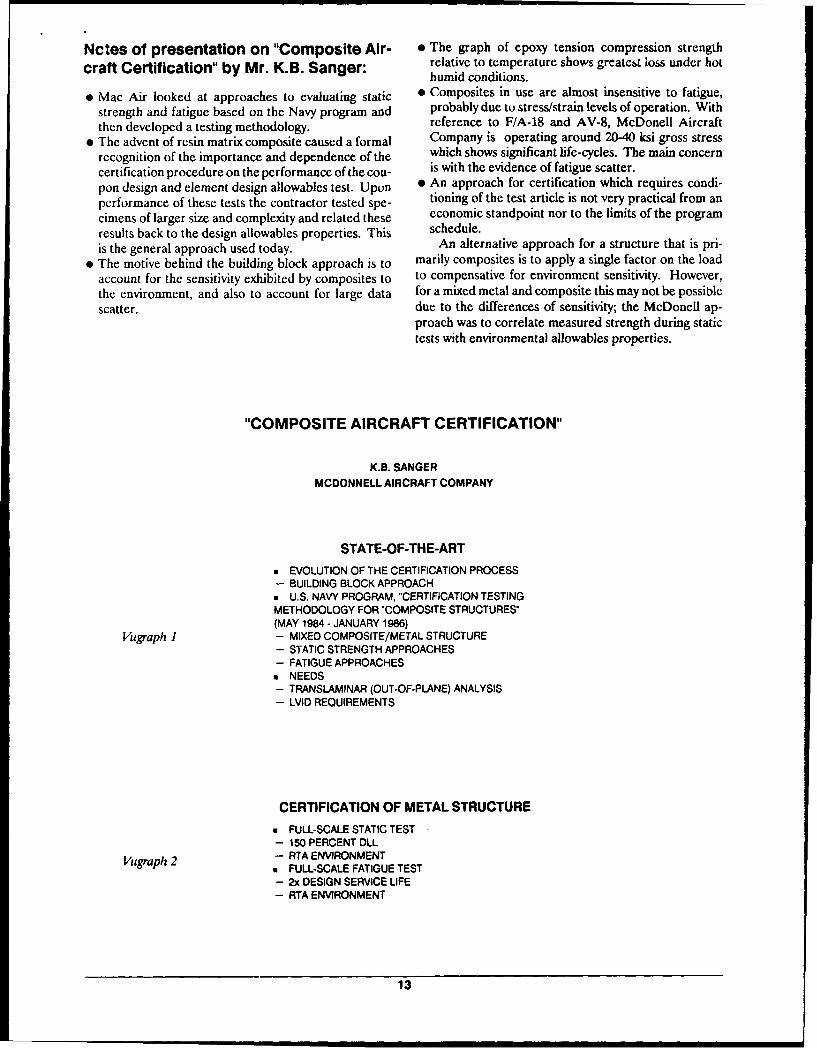
STATE-OF-THE-ART
a EVOLUTION OF THE CERTIFICATION PROCESS- BUILDING BLOCK APPROACH* U.S. NAVY PROGRAM, "CERTIFICATION TESTINGMETHODOLOGY FOR "COMPOSITE STRUCTURES"(MAY 1984 - JANUARY 1986)
Vugraph 1 - MIXED COMPOSITE/METAL STRUCTURE- STATIC STRENGTH APPROACHES- FATIGUE APPROACHES* NEEDS- TRANSLAMINAR (OUT-OF-PLANE) ANALYSIS- LVID REQUIREMENTS
CERTIFICATION OF METAL STRUCTURE
• FULL-SCALE STATIC TEST- 150 PERCENT DLL
Vugraph 2 - RTA ENVIRONMENT* FULL-SCALE FATIGUE TEST- 2x DESIGN SERVICE LIFE- RTA ENVIRONMENT
13

F/A-18 DEVELOPMENTICERTIFICATION TESTS
COUPONS AND ELEMENTS
Vugraph 3
SUBCOMPONENTSAND COMPONENTS
FULL-SCALE ARTICLES z,
F-15 DEVELOPMENT TESTS
STABILATOR LEADING AND TRAILING EDGE SPLICE
WING CARRY THRU LUG JOINT
LOWER WING ROOT KICK JOINT GRAPHITE/EPOXY MATERIAL
Vugraph 4 BORON/EPOXY
POLYCARBONATE EDGEATTACMENTSTABILATOR SPINDLE
TO COVER JOINT
UPP,.ER WING i 9I SKIN STABILITY
LOWER WING SKIN SPLICE XS 155
FORWARD TO CENTER STRINGER TO RIBFUSELAGE SPLICE ATTACH HOLES
14
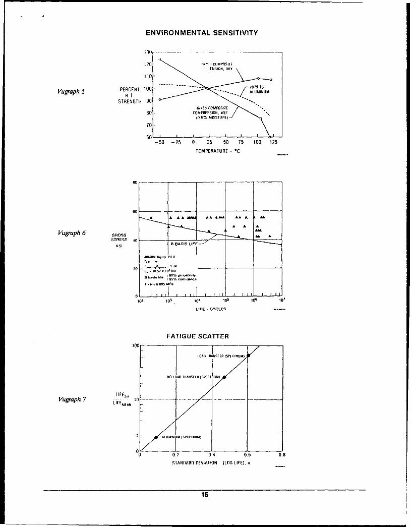
ENVIRONMENTAL SENSITIVITY
303 -- --
120 c ors
VugraphSPERCENT 100R.]
STRENGTHi 90rCIEQ compos~ff
80 -COMPR3SSION. WET
30 % MOISILJRE)
70 -
6-50 -25 0 25 50 75 100 125
TEMPERATURE - 00
go
A A A
Vugraph 6 GROSS
,484 Iay,,p. RTO
Bhs 95% conI.dence.
LIFE -CYCLES
FATIGUE SCATTER
Vugraph 7 10EMA
00 0.? 0 4 0.6 0.8
SIMNARD) nEVIATION (LOG LIFE),
15
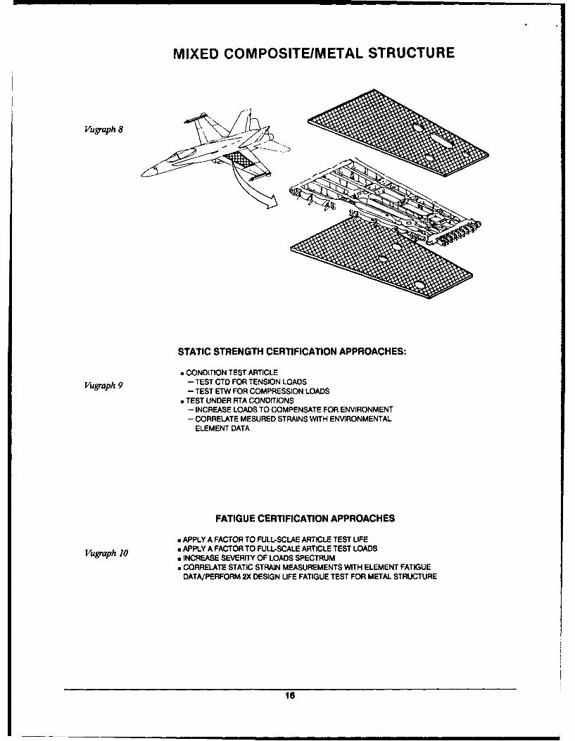
MIXED COMPOSITEIMETAL STRUCTURE
Vugraph 8
STATIC STRENGTH CERTIFICATION APPROACHES:
" CONDITION TEST ARTICLEVugraph 9 - TEST CTD FOR TENSION LOADS
- TEST ETW FOR COMPRESSION LOADS" TEST UNDER RTA CONDITIONS
- INCREASE LOADS TO COMPENSATE FOR ENVIRONMENT
- CORRELATE MESURED STRAINS WITH ENVIRONMENTALELEMENT DATA
FATIGUE CERTIFICATION APPROACHES
m APPLY A FACTOR TO FULL-SCLAE ARTICLE TEST LIFEVuffaph 10 a APPLY A FACTOR TO FULL-SCALE ARTICLE TEST LOADS
w INCREASE SEVERITY OF LOADS SPECTRUMa CORRELATE STATIC STRAIN MEASUREMENTS WITH ELEMENT FATIGUE
DATA/PERFORM 2X DESIGN LIFE FATIGUE TEST FOR METAL STRUCTURE
16
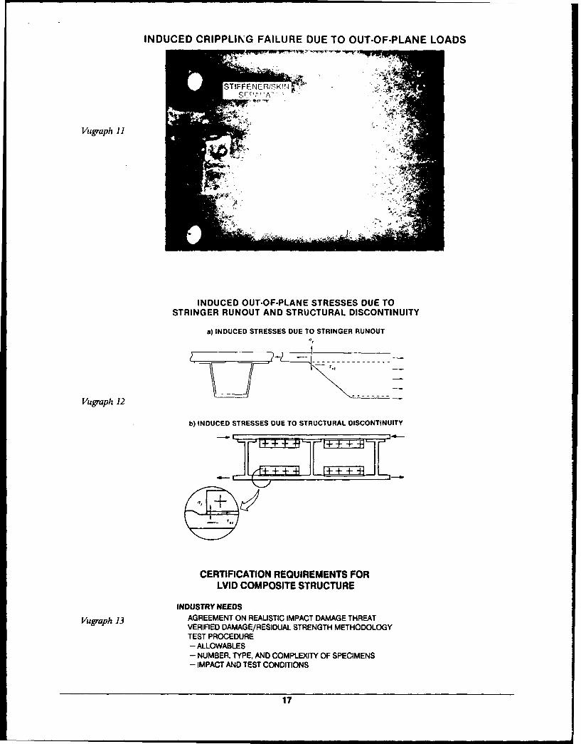
INDUCED CRIPPLING FAILURE DUE TO OUT-OF-PLANE LOADS
STIFFENER, K!,]v 4S ~ r t A ' "< ' '.,
Vugraph 11
INDUCED OUT-OF-PLANE STRESSES DUE TOSTRINGER RUNOUT AND STRUCTURAL DISCONTINUITY
a) INDUCED STRESSES DUE TO STRINGER RUNOUT0,
Vugraph 12
b) INDUCED STRESSES DUE TO STRUCTURAL DISCONTINUITY
CERTIFICATION REQUIREMENTS FOR
LVID COMPOSITE STRUCTURE
INDUSTRY NEEDS
Vugraph 13 AGREEMENT ON REALISTIC IMPACT DAMAGE THREATVERIFIED DAMAGE/RESIDUAL STRENGTH METHODOLOGYTEST PROCEDURE- ALLOWABLES- NUMBER, TYPE, AND COMPLEXITY OF SPECIMENS- IMPACT AND TEST CONDITIONS
17
This page intentionally left blank.
Is
NEW MATERIALS AND FATIGUE RESISTANT AIRCRAFT DESIGN
CERTTFICATION OF PRIMARY COMPOSITE AIRCRAFTSTRUCTURES
R.S. Whitehead*
An overview of the extensive experience, lessonslearned, and recommended certification proceduresfrom two major USAF composite R&D programs ispresented. Subject areas discussed in detail arestatic strength, fatigue/durability, and damagetolerance.
INTRODUCTION
The increased application of advanced composite materials in* air-craft structures requires a critical assessment of the adequacyand applicability of existing metallic oriented certificationspecific~ttions to this emerging class of materials. To do this, itis necessary to recognize the inherent differences between metalsand composites. These inherent property differences led to an adhoc qualification approach for early production hardware. Thisindividual requirement development, or pay-as-you-go approach,while satisfying the immediate need at a "single copy" price,limited generic application and prolonged airframe development.Thus, in the long run, this approach was more expensive andtime-consuming than a subscription price approach, whichrepeatedly uses established standardized specifications. A needexists, therefore. for an orderly, unified, consistent, andverified approach for designing, certifying, and force managingcomposite structures. This need has been addressed in two AirForce sponsored R&D programs. The purpose of these programswas to develop an extensive test data base on specimens rangingin complexity from coupons through elements, element
* Northrop Corporation, Aircraft Division, Hawthorne, California
19
NEW MATERIALS AND FATIGUE RESISTANT AIRCRAFT DESIGN
combinations, subcomponents, and full-scale wing and fuselagestructures. This data base was then used to develop draftcertification specifications for static strength, durability, anddamage tolerance. In addition to the specifications, certificationcompliance procedures were also developed. Details of this workwere presented previously in the open literature in refer-ences 1-8. This paper discusses experience, lessons learned,and recommended certification procedures for static strength,fatigue/durability, and damage tolerance of composite structures.
STATIC STRENGTH
Experience
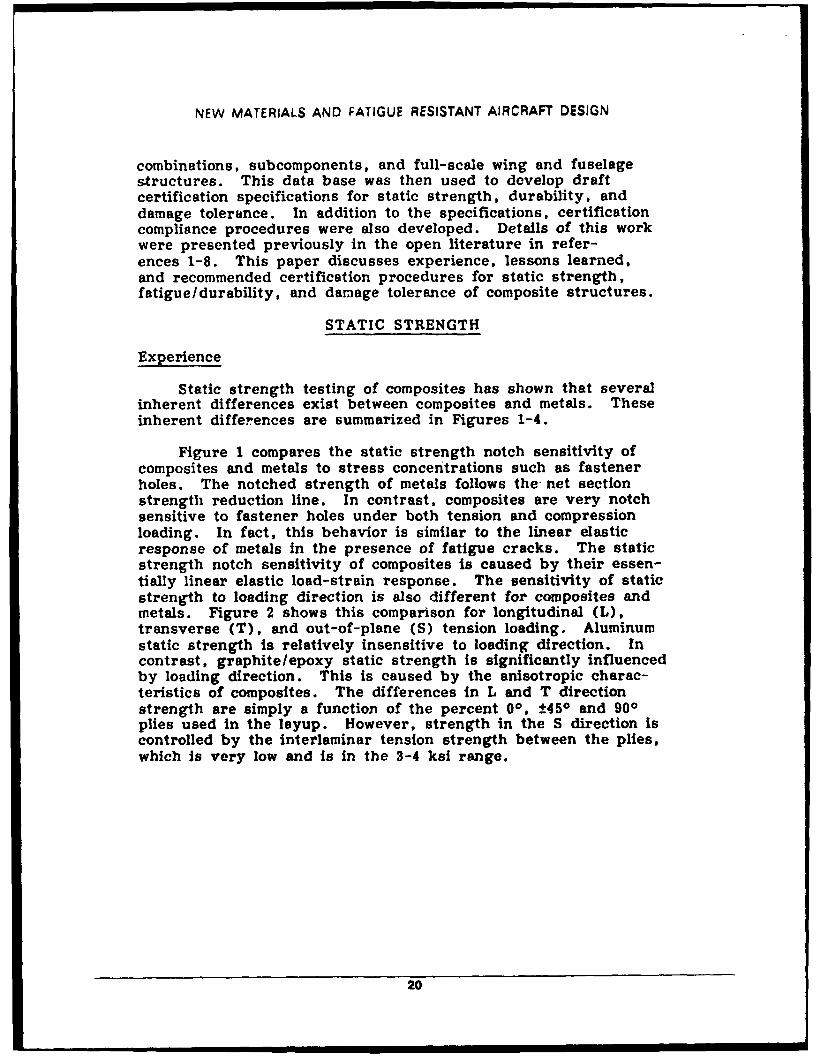
Static strength testing of composites has shown that severalinherent differences exist between composites and metals. Theseinherent differences are summarized in Figures 1-4.
Figure I compares the static strength notch sensitivity ofcomposites and metals to stress concentrations such as fastenerholes. The notched strength of metals follows the net sectionstrength reduction line. In contrast, composites are very notchsensitive to fastener holes under both tension and compressionloading. In fact, this behavior is similar to the linear elasticresponse of metals in the presence of fatigue cracks. The staticstrength notch sensitivity of composites is caused by their essen-tially linear elastic load-strain response. The sensitivity of staticstrength to loading direction is also different for composites andmetals. Figure 2 shows this comparison for longitudinal (L),transverse (T), and out-of-plane (S) tension loading. Aluminumstatic strength Is relatively insensitive to loading direction. Incontrast, graphite/epoxy static strength is significantly influencedby loading direction. This Is caused by the anisotropic charac-teristics of composites. The differences In L and T directionstrength are simply a function of the percent 00, ±450 and 900plies used in the lsyup. However, strength in the S direction iscontrolled by the Interlaminar tension strength between the plies,which is very low and is in the 3-4 ksi range.
20
NFW MATERIALS AND FATIGUE RESISTANT AIRCRAFT DESIGN
1.0 Open Holel
-o0 0.8-- t Metal-C
0
C 0.6C
. Compression)
c 0.4-a)W Composite Tension
_0 0.2-0
Z0.2 0.4 0.6 0.8 1.0 1.2Hole Diameter (in.)
Figure 1 Static notch sensitivity comparison of graphite/epoxyand aluminum to fastener holes
S LE = 10 Msi
150 r- Composite AS413501-6
EM Metal 7075-T6 T
100
C F
0 FO/ fL T
Loading Direction
Figure 2 Influence of loading direction on graphite/epoxy andaluminum static strength
21
NEW MATERIALS AND FATIGUE RESISTANT AIRCRAFT DESIGN
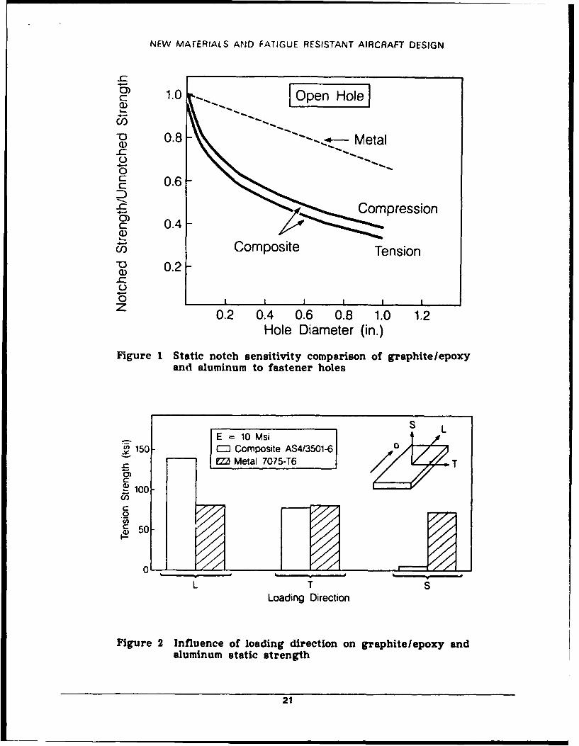
Composites, which exhibit matrix controlled failure modes(9.g., compression), are sensitive to the aircraft hygrothermalenvironment. In particular, the effects of temperature and mois-ture have a synergistic effect. Therefore, the strength degrada-tion of composites in hot/wet environments controls their maximumservice usage temperature. Figure 3 shows the influence oftemperature and moisture content on composite compression staticstrength. These data are for the 350OF cure system AS4/3501-6.Figure 3 shows that as the test temperature is Increased above220 0F, strength loss (relative to ambient) is 15 percent, while at2500 strength loss is more than doubled to 33 percent. Thislarge strength loss is due to rapid degeneration in resin prop-erties (e.g., shear stiffness), which is caused by the resinapproaching it6 glass transition temperature. In contrast, Fig-ure 3 shows that aluminum strength is much less sensitive to tem-perature. Figure 4 compares the static strength variability ofcomposites and metals. Because of their anisotropic heteroge-neous characteristics, composites exhibit higher variability forlaminate failure modes. For cocured composite-to-composite failuremodes, even higher variability (10 percent coefficient of var-iation) is observed. This causes the ratio of the B-basics designallowable to mean value to be lower for composites compared tometals.
--o 100
~80 CD MetalC9) 705-T6)
C0 S40Composite
40 -0(AS4/3501-6)O. 1.2% MoistureEo 20 O
I-
100 200 300Temperature (F)
Figure 3 Influence of environment on compression staticstrength retention
22
NEW MATERIALS AND FATIGUE RESISTANT AIRCRAFT DESIGN
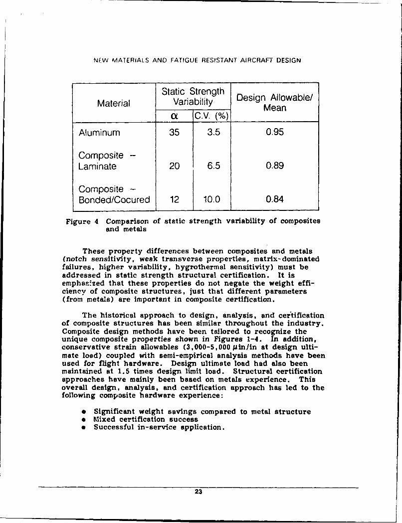
Static Strength Design Allowable/Material Variability ManMean
t C.V. (%)
Aluminum 35 3.5 0.95
Composite -Laminate 20 6.5 0.89
Composite -Bonded/Cocured 12 10.0 0.84
Figure 4 Comparison of static strength variability of compositesand metals
These property differences between composites and metals(notch sensitivity, weak transverse properties, matrix-dominatedfailures, higher variability, hygrothermal sensitivity) must beaddressed in static strength structural certification. It isemphas-zed that these properties do not negate the weight effi-ciency of composite structures, just that different parameters(from metals) are important in composite certification.
The historical approach to design, analysis, and certificationof composite structures has been similar throughout the industry.Composite design methods have been tailored to recognize theunique composite properties shown in Figures 1-4. In addition,conservative strain allowables (3,000-5,000 Min/in at design ulti-mate load) coupled with semi-empirical analysis methods have beenused for flight hardware. Design ultimate load had also beenmaintained at 1.5 times design limit load. Structural certificationapproaches have mainly been based on metals experience. Thisoverall design, analysis, and certification approach has led to thefollowing composite hardware experience:
" Significant weight savings compared to metal structure" Mixed certification successe Successful in-service application.
23
NEW MATERIALS AND FATIGUE RESISTANT AIRCRAFT DESIGN
Problems associated with the static strength certification ofcomposite structures are discussed below.
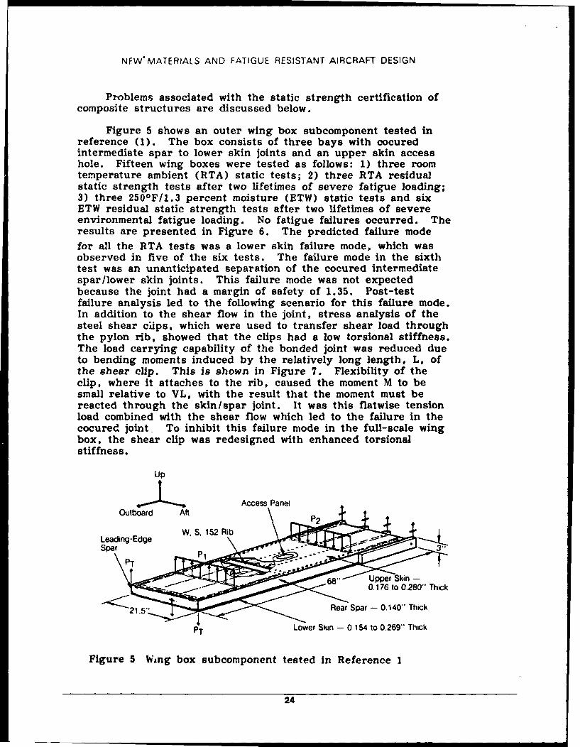
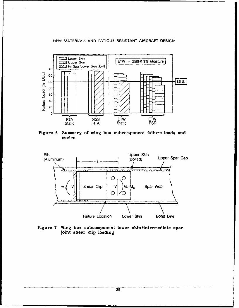
Figure 5 shows an outer wing box subcomponent tested inreference (1). The box consists of three bays with cocuredintermediate spar to lower skin joints and an upper skin accesshole. Fifteen wing boxes were tested as follows: 1) three roomtemperature ambient (RTA) static tests; 2) three RTA residualstatic strength tests after two lifetimes of severe fatigue loading;3) three 250°F/1.3 percent moisture (ETW) static tests and sixETW residual static strength tests after two lifetimes of severeenvironmental fatigue loading. No fatigue failures occurred. Theresults are presented in Figure 6. The predicted failure modefor all the RTA tests was a lower skin failure mode, which wasobserved in five of the six tests. The failure mode in the sixthtest was an unanticipated separation of the cocured intermediatespar/lower skin joints. This failure mode was not expectedbecause the joint had a margin of safety of 1.35. Post-testfailure analysis led to the following scenario for this failure mode.In addition to the shear flow in the joint, stress analysis of thesteel shear cips, which were used to transfer shear load throughthe pylon rib, showed that the clips had a low torsional stiffness.The load carrying capability of the bonded joint was reduced dueto bending moments induced by the relatively long length, L, ofthe shear clip. This is shown in Figure 7. Flexibility of theclip, where It attaches to the rib, caused the moment M to besmall relative to VL, with the result that the moment must bereacted through the skin/spar joint. It was this flatwise tensionload combined with the shear flow which led to the failure in thecocured joint To inhibit this failure mode in the full-scale wingbox, the shear clip was redesigned with enhanced torsionalstiffness.
Up
Access Panel
Leading-EdgeSpar T 'L.. P1 "
6" Upper Skin -- - . /. 0.176 to 0.280" Thick
- "'21.5" Rear Spar - 0.140" Thick
PT Lower Skin - 0 154 to 0.269"' Thick
Figure 5 Wing box subcomponent tested in Reference 1
24
NEW MATERIALS AND FATIGUE RESISTANT AIRCRAFT DESIGN
EJLower Skin -WE~Upper Skin FET 250F/1.3% Moisture140 - t Spar/Lower Skin Joint
S120
100 -71 -F RT- U
80*0
o 60
E) 40
'Fa 20LL
0 k-W- - -
RTA RSS ETW E1'vStatic RTA Static RSS
Figure 6 Summary of wing box subcomponent failure loads andmod~es
Rib Upper Skin(Aluminum) jL (Bolted) Upper Spar Cap
a V Shear Clip V )VL-M 0 Spar Web
Failure Location Lower Skin Bond Line
Figure 7 Wing box subcomponent lower skin /intermediate sparjoint shear clip loading
25
NEW MATERIALS AND FATIGUE RESISTANT AIRCRAFT DESIGN
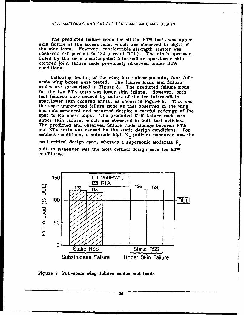
The predicted failure mode for all the ETW tests was upperAkin failure at the access hole, which was observed in eight ofthe nine tests. However, considerable strength scatter wasobserved (87 percent to 132 percent DUL). The ninth specimenfailed by the same unanticipated intermediate spar/lower skincocured joint failure mode previously observed under RTAconditions.
Following testing of the wing box subcomponents, four full-scale wing boxes were tested. The failure loads and failuremodes are summarized in Figure 8. The predicted failure modefor the two RTA tests was lower skin failure. However, bothtest failures were caused by failure of the ten intermediatesparilower skin cocured joints, as shown in Figure 9. This wasthe same unexpected failure mode as that observed in the wingbox subcomponent and occurred despite a careful redesign of thespar to rib shear clips. The predicted ETW failure mode wasupper skin failure, which was observed in both test articles.The predicted and observed failure mode change between RTAand ETW tests was caused by the static design conditions. Forambient conditions, a subsonic high Nz pull-up maneuver was the
most critical design case, whereas a supersonic moderate N z
pull-up maneuver was the most critical design case for ETWconditions.
150 ED 250F/Wet
122 126 124Z)118,
S100- -DULV0-J
50
LL
Static RSS Static RSS
Substructure Failure Upper Skin Failure
Figure 8 Full-scale wing failure modes and loads
26
NFW MA]FRAtS AND FAIIGUE RESISTANT AIRCRAFT DESIGN
FRONT ROOT RIB
...................... ..... . PYLON RIB.. . . . . . -. -.. . ..
83-03239-5
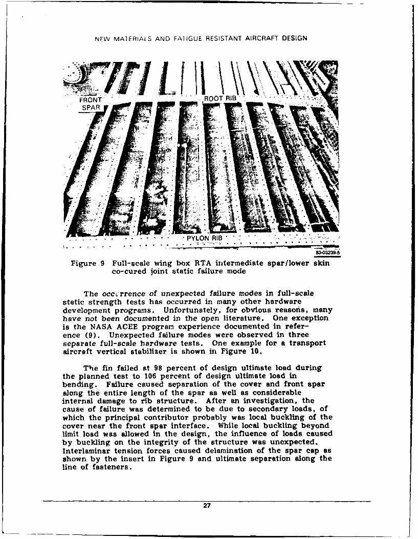
Figure 9 Full-scale wing box RTA intermediate spar/lower skinco-cured joint static failure mode
The occ..:rrence of unexpected failure modes in full-scalestatic strength tests has occurred in many other hardwaredevelopment programs. Unfortunately, for obvious reasois, manyhave not been documented in the open literature. One exceptionis the NASA ACEE program experience documented in refer-ence (9). Unexpected failure modes were observed in threeseparate full-scale hardware tests. One example for a transportaircraft vertical stabilizer is shown in Figure 10.
The fin failed at 98 percent of design ultimate load duringthe planned test to 106 percent of design ultimate load inbending. Failure caused separation of the cover and front sparalong the entire length of the spar as well as considerableinternal damage to rib structure. After an investigation, thecause of failure was determined to be due to secondary loads, ofwhich the principal contributor probably was local buckling of thecover near the front spar interface. While local buckling beyondlimit load was allowed in the design, the influence of loads causedby buckling on the integrity of the structure was unexpected.Interlaminar tension forces caused delamination of the spar cap asshown by the insert in Figure 9 and ultimate separation along theline of fasteners.
27
NEW MATERIALS AND FATIGUE RESISTANT AIRCRAFT DESIGN
1 ,450) Cover
Typical Spar CapDamage in Primary
(:t_450)s Failure Zone
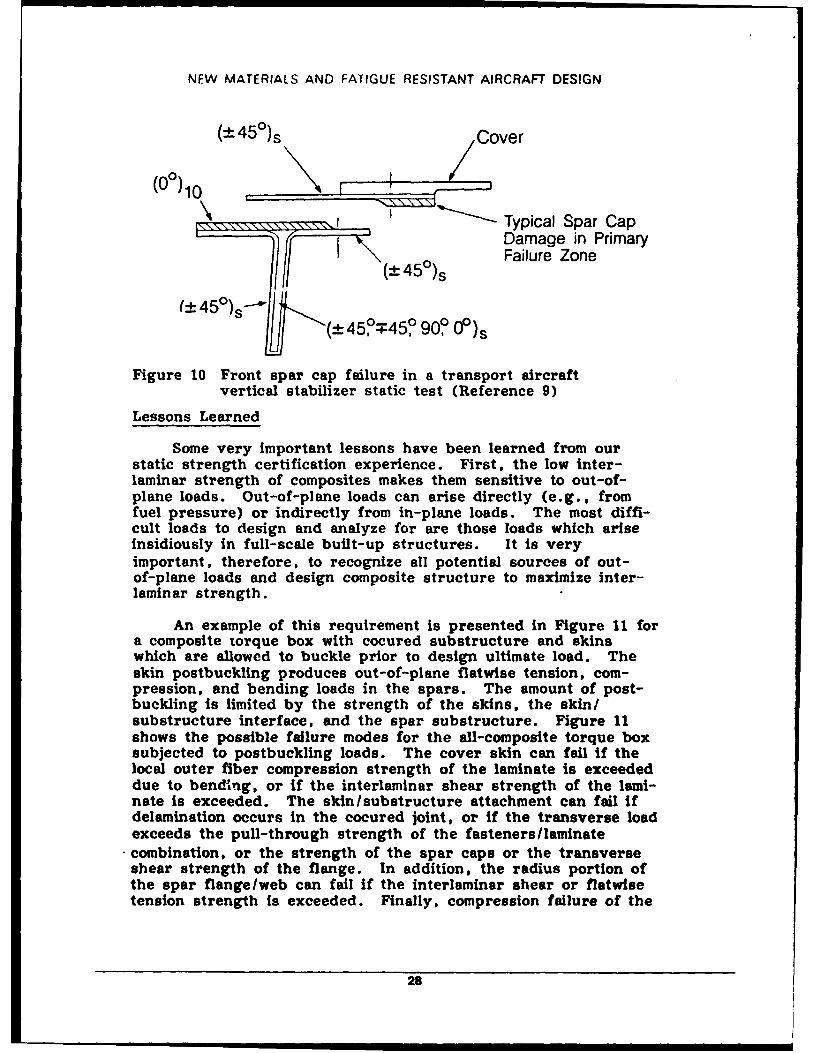
/_ 45°)s- (-"*-±45o=45, 90? 0°)s
Figure 10 Front spar cap failure in a transport aircraftvertical stabilizer static test (Reference 9)
Lessons Learned
Some very important lessons have been learned from ourstatic strength certification experience. First, the low inter-laminar strength of composites makes them sensitive to out-of-plane loads. Out-of-plane loads can arise directly (e.g., fromfuel pressure) or indirectly from in-plane loads. The most diffi-cult loads to design and analyze for are those loads which ariseinsidiously in full-scale built-up structures. It is veryimportant, therefore, to recognize all potential sources of out-of-plane loads and design composite structure to maximize inter-laminar strength.
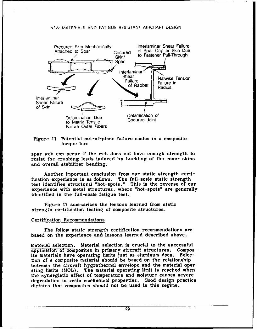
An example of this requirement is presented in Figure 11 fora composite torque box with cocured substructure and skinswhich are allowed to buckle prior to design ultimate load. Theskin postbuckling produces out-of-plane flatwise tension, com-pression, and bending loads in the spars. The amount of post-buckling Is limited by the strength of the skins, the skin/substructure interface, and the spar substructure. Figure 11shows the possible failure modes for the all-composite torque boxsubjected to postbuckling loads. The cover skin can fail if thelocal outer fiber compression strength of the laminate is exceededdue to bending, or if the interlaminar shear strength of the lami-nate is exceeded. The skin/substructure attachment can fail ifdelamination occurs in the cocured joint, or if the transverse loadexceeds the pull-through strength of the fasteners /laminatecombination, or the strength of the spar caps or the transverseshear strength of the flange. In addition, the radius portion ofthe spar flange/web can fail if the Interlaminar shear or flatwisetension strength is exceeded. Finally, compression failure of the
28
NEW MATERIALS AND FATIGUE RESISTANT AIRCRAFT DESIGN
Precured Skin Mechanically Interlaminar Shear FailureAttached to Spar Cocured of Spar Cap or Skin Due
-- Skin/ to Fastener Pull-Through
- interlainarShear e Flatwise Tension\ N Failure Failure in
of Rabbet Radius
inteflarnfarShear Failureof Skin Dea / --
'elamination Due DelamInation ofto Matrix Tensile Cocured JointFailure Outer Fibers
Figure 11 Potential out-of-plane failure modes in a compositetorque box
spar web can occur if the web does not have enough strength toresist the crushing loads induced by buckling of the cover skinsand overall stabilizer bending.
Another important conclusion from our static strength certi-fication experience is as follows. The full-scale static strengthtest identifies structural "hot-spots." This is the reverse of ourexperience with metal structures, where "hot-spots" are generallyidentified in the full-scale fatigue test.
Figure 12 summarizes the lessons learned from static
strength certification testing of composite structures.
Certification Recommendations
The follow static strength certification recommendations arebased on the experience and lessons learned described above.
Material selection. Material selection is crucial to the successfulapplication of composites in primary aircraft structures. Compos-ite materials have operating limits just as aluminum does. Selec-tion of a composite material should be based on the relationshipbetween the r-rcraft hygrothermal envelope and the material oper-ating limits (MOL). The material operating limit is reached whenthe synergistic effect of temperature and moisture causes severedegradation In resin mechanical properties. Good design practicedictates that composites should not be used in this regime.
29
NEW MATERIALS AND FATIGUE RESISTANT AIRCRAFT DESIGN
* Inherent Property Differences Exist Between Composites and Metals* Composite Structures Are Sensitive to Out-of-Plane Loads* Multiplicity of Potential Failure Modes* Failure Modes of Full-Scale Structures Are Difficult To Predict* Static-Strength Test Identifies Structural "Hot Spots"
Figure 12 Summary of lessons learned from static strengthcertification testing of composite structures
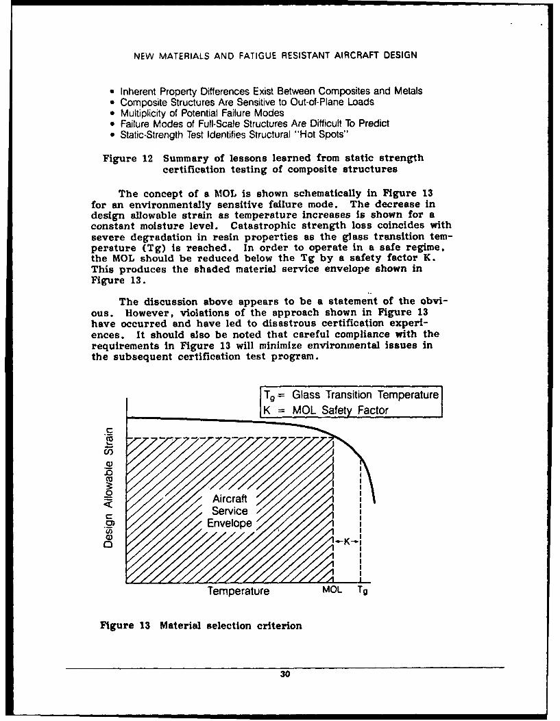
The concept of a MOL is shown schematically in Figure 13for an environmentally sensitive failure mode. The decrease indesign allowable strain as temperature increases is shown for aconstant moisture level. Catastrophic strength loss coincides withsevere degradation in resin properties as the glass transition tem-perature (Tg) is reached. In order to operate in a safe regime,the MOL should be reduced below the Tg by a safety factor K.This produces the shaded material service envelope shown inFigure 13.
The discussion above appears to be a statement of the obvi-ous. However, violations of the approach shown in Figure 13have occurred and have led to disastrous certification experi-ences. It should also be noted that careful compliance with therequirements in Figure 13 will minimize environmental issues inthe subsequent certification test program.
Tg = Glass Transition TemperatureK MOL Safety Factor
C
I.-U)
~0< / Aircraft0 SService //
Envelope(/)
Temperature MOL Tg
Figure 13 Material selection criterion
30
NFW MATERIALS AND FATIGUE RESISTANT AIRCRAFT DESIGN
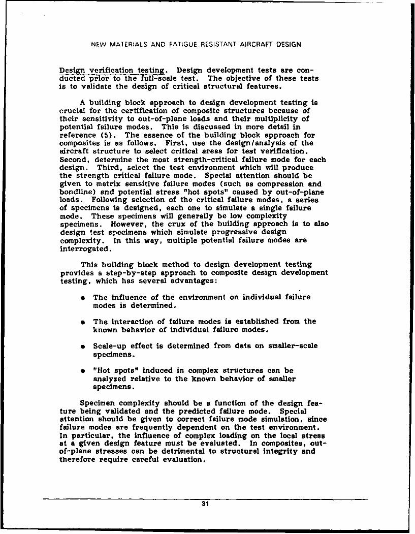
Design verification testing. Design development tests are con-ducted prior to the full-scale test. The objective of these testsis to validate the design of critical structural features.
A building block approach to design development testing iscrucial for the certification of composite structures because oftheir sensitivity to out-of-plane loads and their multiplicity ofpotential failure modes. This is discussed in more detail inreference (5). The essence of the building block approach forcomposites is as follows. First, use the design/analysis of theaircraft structure to select critical areas for test verification.Second, determine the most strength-critical failure mode for eachdesign. Third. select the test environment which will producethe strength critical failure mode. Special attention should begiven to matrix sensitive failure modes (such as compression andbondline) and potential stress "hot spots" caused by out-of-planeloads. Following selection of the critical failure modes, a seriesof specimens is designed, each one to simulate a single failuremode. These specimens will generally be low complexityspecimens. However, the crux of the building approach is to alsodesign test specimens which simulate progressive designcomplexity. In this way, multiple potential failure modes areinterrogated.
This building block method to design development testingprovides a step-by-step approach to composite design developmenttesting, which has several advantages:
" The influence of the environment on individual failuremodes is determined.
" The interaction of failure modes is established from theknown behavior of individual failure modes.
" Scale-up effect is determined from data on smaller-scalespecimens.
" "Hot spots" induced in complex structures can beanalyzed relative to the known behavior of smallerspecimens.
Specimen complexity should be a function of the design fea-ture being validated and the predicted failure mode. Specialattention should be given to correct failure mode simulation, sincefailure modes are frequently dependent on the test environment.In particular, the influence of complex loading on the local stressat a given design feature must be evaluated. In composites, out-of-plane stresses can be detrimental to structural integrity andtherefore require careful evaluation.
31
NEW MATERIALS AND FATIGUE RESISTANT AIRCRAFT DESIGN
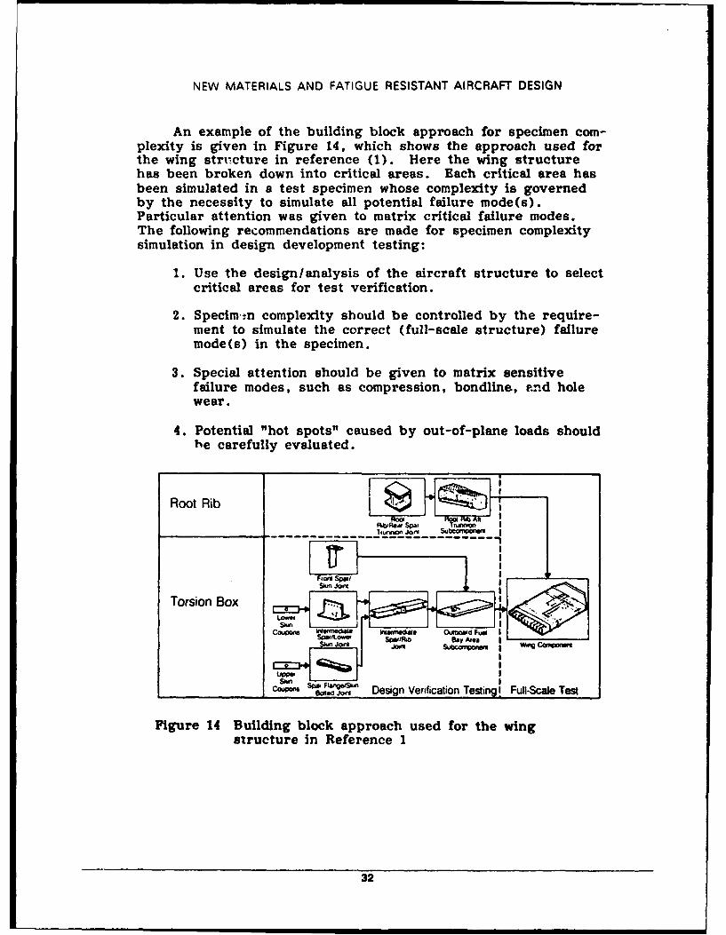
An example of the building block approach for specimen com-plexity is given In Figure 14, which shows the approach used forthe wing stru~cture in reference (1). Here the wing structurehas been broken down into critical areas. Each critical area hasbeen simulated in a test specimen whose complexity is governedby the necessity to simulate all potential failure mode(s).Particular attention was given to matrix critical failure modes.The following recommendations are made for specimen complexitysimulation in design development testing:
1. Use the design/analysis of the aircraft structure to selectcritical areas for test verification.
2. Specimen complexity should be controlled by the require-ment to simulate the correct (full-scale structure) failuremode(s) in the specimen.
3. Special attention should be given to matrix sensitivefailure modes, such as compression, bondline, .nd holewear.
4. Potential "hot spots" caused by out-of-plane loads shouldhe carefully evaluated.
Root Rib
Torsion Box F,.L n Vr4aoT i
F, _ S ipo F .,
,,, j6,' Design Verification Testing!I Full-Scale Test
Figure 14 Building block approach used for the wingstructure in Reference 1
32
NEW MATERIALS AND FATIGUE RESISTANT AIRCRAFT DESIGN
The sensitivity of composite matrix dominated failure modesto the aircraft hygrothermal environment makes environmental testsimulation a key issue. Environmental test simulation should beconsidered separately for static and durability testing. However,the static test philosophy will form an integral part of the overalltest philosophy. The philosophy for static design developmenttests should be that the test environment used will be the onethat produces the failure mode which gives the lowest staticstrength.
Full-scale test. The full-scale static test is the most crucialqualification test for composite structures for the followingreasons. Secondary loads are virtually impossible to eliminatefrom complex built-up structures. Such loads can be producedby eccentricities, stiffness changes, discontinuities, fuel pressureloading, and loading in the post-buckled range. Some of thesesources of secondary loads are represented for the first time inthe full-scale structural test article. These loads are not asignificant design driver in metallic structures. However, thepoor interlaminar strength of composites makes them extremelysusceptible to out-of-plane secondary loads. It is very impor-tant, therefore, to carefully account for these loads in the designof composite structures. Unfortunately, there is a general stateof uncertainty as to the source, magnitude, and effects of secon-dary loads in complex built-up full-scale composite structures.This has been confirmed by several documented examples of
unanticipated secondary loads leading to unexpected failure modesin full-scale composite structural static tests.
In addition, a detailed correlation in terms of measured loadand strain distributions, structural analysis data, and environ-mental effects between the design development and full-scale testdata will be necessary to provide assurance of composite staticstrength. Static test environmental degradation must beaccounted for separately either by adverse condition testing, byadditional test design factors, or by correlation with environ-mental design development test data.
Work in reference (1) has shown that the RT/ambient statictest plays the most significant role in revealing unexpected hotspot failures from secondary out-of-plane loads. A roomtemperature environment is, therefore, recommended for thefull-scale static test, which should be conducted to failure. Thisrecommendation is not universally accepted by all certificationagencies. Some agencies favor an environmental static test whichcorresponds to the temperature and absorbed moisture level of themost critical static design condition. This issue is mostsignificant ir, fighter aircraft where a hot/wet failure mode isoften the most critical design condition. Unfortunately, afull-scale environmental static test is very expensive andtime-consuming. A possible solution to this problem, proposed by
33
NFW MAIERIALS AND FATIGUE RESISTANT AIRCRAFT DESIGN
Dr. Lincoln in reference (3), is as follows: the designphilosophy would not permit any significant change in failuremode due to environment. For example, consider an aircraftstructure, where the most critical design load condition isassociated with a hot/wet environment. The requirement of thisphilosophy would be for the structure to be designed to have thesame failure mode under both hot/wet and RT/embient conditions.This approach would eliminate the need for hot/wet qualificationtesting. If this design requirement had been adopted for thefighter aircraft wing structure in reference (1), a weight penaltyof approximately 6 percent would have been incurred in the mainwing box structure.
FATIGUE/DURABILITY
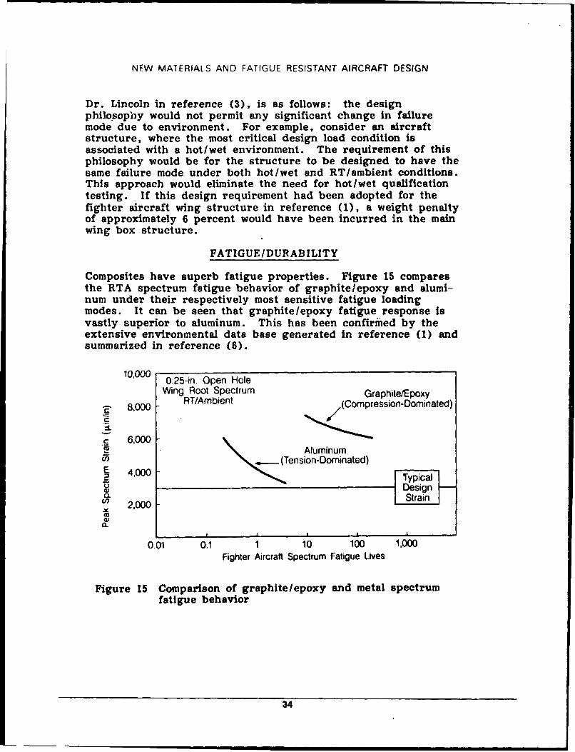
Composites have superb fatigue properties. Figure 15 comparesthe RTA spectrum fatigue behavior of graphite/epoxy and alumi-num under their respectively most sensitive fatigue loadingmodes. It can be seen that graphite/epoxy fatigue response Isvastly superior to aluminum. This has been confirmned by theextensive environmental data base generated in reference (1) andsummarized in reference (6).
10,000 0.25-in. Open Hole
Wing Root Spectrum Graphite/Epoxy
8,000 RT/Ambient (Compression-Dominated)
6,000 c 6,000Aluminumcn Tension-Dominated)2 '0 Typical .
Design200Strain
oo 2000
00.
0.01 0.1 1 10 100 1,000Fighter Aircraft Spectrum Fatigue Lives
Figure 15 Comparison of graphite/epoxy and metal spectrumfatigue behavior
34
NEW MATERIALS AND FATIGUE RESISTANT AIRCRAFT CESIGN
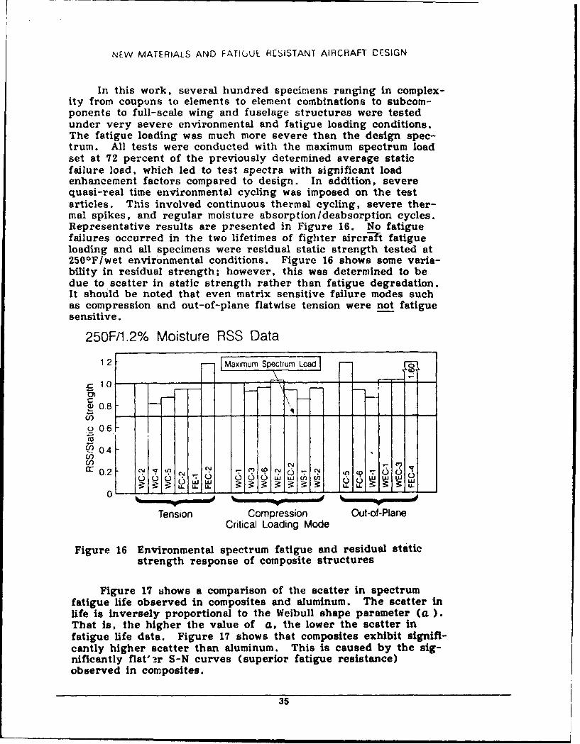
In this work, several hundred specimens ranging in complex-ity from coupons to elements to element combinations to subcom-ponents to full-scale wing and fuselage structures were testedunder very severe environmental and fatigue loading conditions.The fatigue loading was much more severe than the design spec-trum. All tests were conducted with the maximum spectrum loadset at 72 percent of the previously determined average staticfailure load, which led to test spectra with significant loadenhancement factors compared to design. In addition, severequasi-real time environmental cycling was imposed on the testarticles. This involved continuous thermal cycling, severe ther-mal spikes, and regular moisture absorption/deabsorption cycles.Representative results are presented in Figure 16. No fatiguefailures occurred in the two lifetimes of fighter aircra't fatigueloading and all specimens were residual static strength tested at250 0F/wet environmental conditions. Figure 16 shows some varia-bility in residual strength; however, this was determined to bedue to scatter In static strength rather than fatigue degradation.It should be noted that even matrix sensitive failure modes suchas compression and out-of-plane flatwise tension were not fatiguesensitive.
250F/1.2% Moisture RSS Data
1 2 -Maximum SpectrumLd
C
4) 0.8 - - - -
o0,6
0404
cc0.2 c~j-qinu'
I 1____ -. - - - - - - - - - - - - - - - - - - - - - - - - -
Tension Compression Out-of-PlaneCritical Loading Mode
Figure 16 Environmental spectrum fatigue and residual staticstrength response of composite structures
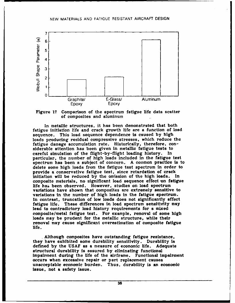
Figure 17 s~hows a comparison of the scatter in spectrumfatigue life observed in composites and aluminum. The scatter inlife Is inversely proportional to the Weibull shape parameter (a.)That is, the higher the value of a, the lower the scatter infatigue life date. Figure 17 shows that composites exhibit signifi-cantly higher scatter than aluminum. This is caused by the sig-nificantly flat'16r S-N curves (superior fatigue resistance)observed in composites.
35
NEW MATERIALS AND FATIGUE RESISTANT AIRCRAFT DESIGN
7
~6F
G) 5E
M 4
a)O 3-c
-- 2-5
0
Graphite/ E-Glass/ AluminumEpoxy Epoxy
Figure 17 Comparison of the spectrum fatigue life data scatterof composites and aluminum
In metallic structures, it has been demonstrated that bothfatigue initiation life and crack growth life are a function of loadsequence. This load sequence dependence is caused by highloads producing residual compressive stresses, which reduce thefatigue damage accumulation rate. Historically, therefore, con-siderable attention has been given in metallic fatigue tests tocareful simulation of the flight-by-flight loading history. Inparticular, the number of high loads included in the fatigue testspectrum has been a subject of concern. A common practice is todelete some high loads from the fatigue test spectrum in order toprovide a conservative fatigue test, since retardation of crackinitiation will be reduced by the omission of the high loads. Incomposite materials, no significant load sequence effect on fatiguelife hab been observed. However, studies on load spectrumvariations have shown that composites are extremely sensitive tovariations in the number of high loads in the fatigue spectrum.In contrast, truncation of low loads does not significantly affectfatigue life. These differences in load spectrum sensitivity maylead to contradictory load history requirements for a mixedcomposite/metal fatigue test. For example, removal of some highloads may be prudent for the metallic structure, while theirremoval may cause significant overestimation of composite fatiguelife.
Although composites have outstanding fatigue resistance,they have exhibited some durability sensitivity. Durability isdefined by the USAF as a measure of economic life. Adequatestructural durability is assured by eliminating functionalimpairment during the life of the airframe. Functional impairmentoccurs when excessive repair or part replacement causesunacceptable economic burden. Thus, durability is an economicissue, not a safety issue.
36
NEW MATERIALS AND FATIGUE RESISTANT AIRCRAFT DESIGN
The durability in-service experience with monolithic struc-tures has been excellent. However, durability experience withthin-skinned honeycomb structure has been less satisfactory.The following problems have occurred:
" Sensitivity to low-level impacts (K 10 ft-lb), causingvisible skin damage, nonvisible skin or core damage,accelerated moisture intrusion, and core corrosion
" High repair frequency
" Excessive part replacement.
These problems have caused unacceptable maintainability and sup-portability costs.
Lessons Learned
Two major lessons have been learned from our compositefatigue/durability experience. These are:
1. Composites have outstanding fatigue resistance. For real-istic structural laminates in typical design applications,composite structures can be considered to be fatigueinsensitive, if they possess adequate static strength.
2 Maintainability and supportability of thin-skinnedhoneycomb structures has been poor.
Certification Recommendations
Detailed recommendations are given in reference (1); and aresummarized below.
Load Spectrum Simulation. The same general guidelinesestablished for metallic structures should be used. The followingrecommendations are made for load spectrum simulation in com-posite fatigue testing:
" High loads in the fatigue spectrum must be carefullysimulated.
" Low loads (< 30 percent limit load stress) may be trun-cated to save test time without significantly affectingfatigue life.
Mixed compo Ate/metal structure. Because of the superior fatigueperformance of composites, a mixed composite/metal structurefatigue will essentially interrogate adequately only the metalstructure. Thus, any potential "hot spots" in the compositestructure may not be found.
37
NEW MATERIALS AND FATIGUE RESISTANT AIRCRAFT DESIGN
Because of the potential inadequacy of full-scale tests onmixed composite/metal structures and also the natural reluctanceto overdesign metal parts in a full-scale test structure, it will benecessary to validate the composite structure during the designdevelopment testing phase. However, the specimen complexityshould be adequate to enable the performance of the full-scalestructure to be correctly simulated. Validation of the compositestructure using subcomponent tests can offer the followingadvantages:
" The components may be chosen for test purposes to inter-rogate the composite structure only.
" If environmental test conditions are required, it will beeasier and cheaper to achieve in a component.
" It may be possible to test more than one replicate andthus increase confidence in the data base.
* The results can be utilized in the certification of thefull-scale structure.
For component tests to achieve their objective, great caremust be taken in getting the boundary conditions correct. Inaddition, eliminating metal failure modes by overdesign orreplacement must be carefully evaluated so that relative effectssuch as differential thermal expansion are not masked.
Environmental simulation. The environmental complexity necessaryfor fatigue design development testing will depend on the aircrafthygrothermal history. Three factors must be considered. Theseare: structural temperatures for each mission profile, the load/temperature relationship for the aircraft, and the moisture. contentas a function of aircraft usage and structure thickness: In orderto obtain these data, it is necessary to derive real-time load-temperature profiles for each misson in the aircraft's history.These relationships will have a significant influence on the fatiguetest enviroiiment, and are strongly dependent on the aircrafttype, configuration, and mission requirements and must be care-fully developed on a case-by-case basis. The structural materialshould be selected to meet these mission requirements using thecriterion In Figure 13. If this is accomplished, hot/wet fatiguetesting will be minimized. Material selections which lead to sig-nificant environmental fatigue test requirements should be a lastresort.
Scatter. The large scatter in composite fatigue life data makesthe traditional life factor approach used for metals impracticalbecause equivalent composite life scatter factors are in the 20-70range. Alternate approaches to account for scatter effects wereevaluated in reference (10).
38
NEW MATERIALS AND FATIGUE RESISTANT AIRCRAFT DESIGN
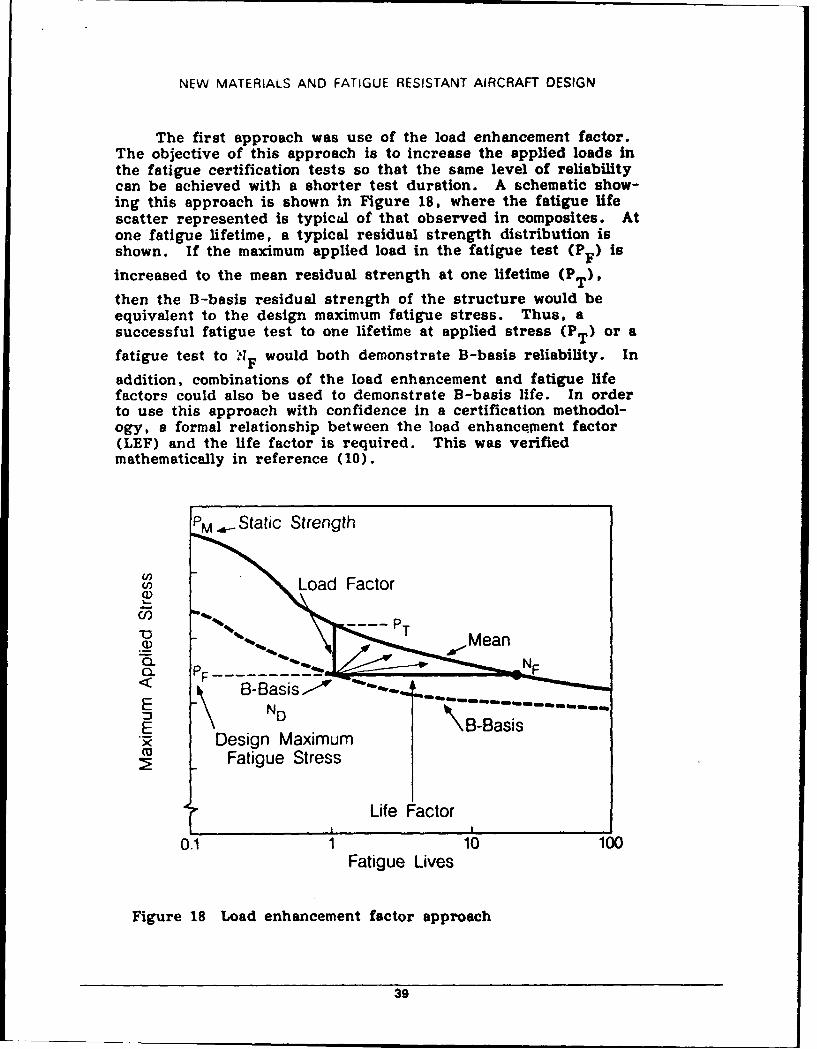
The first approach was use of the load enhancement factor.The objective of this approach is to increase the applied loads inthe fatigue certification tests so that the same level of reliabilitycan be achieved with a shorter test duration. A schematic show-ing this approach is shown in Figure 18, where the fatigue lifescatter represented is typical of that observed in composites. Atone fatigue lifetime, a typical residual strength distribution isshown. If the maximum applied load in the fatigue test (P F is
increased to the mean residual strength at one lifetime (PT)
then the B-basis residual strength of the structure would beequivalent to the design maximum fatigue stress. Thus, asuccessful fatigue test to one lifetime at applied stress (PT) or a
fatigue test to *IA would both demonstrate B-basis reliability. In
addition, combinations of the load enhancement and fatigue lifefactors could also be used to demonstrate B-basis life. In orderto use this approach with confidence in a certification methodol-ogy, a formal relationship between the load enhancement factor(LEF) and the life factor is required. This was verifiedmathematically in reference (10).
PM .Static Strength
SLoad Factor
"U).. PT
,,, ,..M ean
E \B-Basis
• Design MaximumFatigue Stress
Life Factor
0.1 1 10 100Fatigue Lives
Figure 18 Load enhancement factor approach
39
NEW MATERIALS AND FATIGUE RESISTANT AIRCRAFT DESIGN
While the evaluation of the enhanced loads approach inreference (10) has shown that it has a sound theoretical basisand can be used with confidence for certification testing, somepractical limits of this approach exist. First, for asymmetricspectra, the degree of load enhancement may be limited becauseof a requirement not to exceed ultimate load. Second, for mixedstructures, the enhanced load approach will provide anexcessively severe fatigue test for the metal parts.
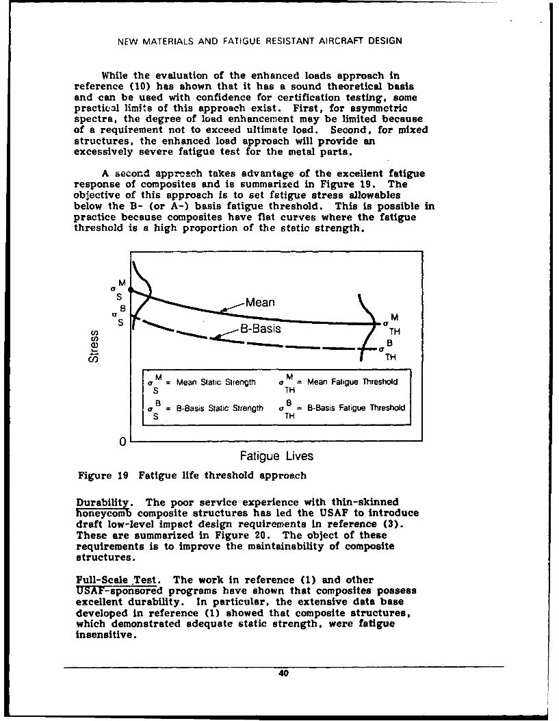
A second apprcach takes advantage of the excellent fatigueresponse of composites and is summarized in Figure 19. Theobjective of this approach is to set fatigue stress allowablesbelow the B- (or A-) basis fatigue threshold. This is possible inpractice because composites have flat curves where the fatiguethreshold is a high proportion of the static strength.
Ma t
B M
B -Basis TH
TH
a = Mean Static Strength a = Mean Fatigue ThresholdS THB B
oB = B-Basis Static Strength a = B-Basis Fatigue ThresholdS TH
0Fatigue Lives
Figure 19 Fatigue life threshold approach
Durability. The poor service experience with thin-skinnedhoreyom composite structures has led the USAF to introducedraft low-level impact design requirements in reference (3).These are summarized in Figure 20. The object of theserequirements is to improve the maintainability of compositestructures.
Full-Scale Test. The work in reference (1) and otherUSAF-sponsored programs have shown that composites possessexcellent durability. In particular, the extensive data basedeveloped in reference (1) showed that composite structures,which demonstrated adequate static strength. were fatigueinsensitive.
40
NEW MATERIALS AND FATIGUE RESISTANT AIRCRAFT DESIGN
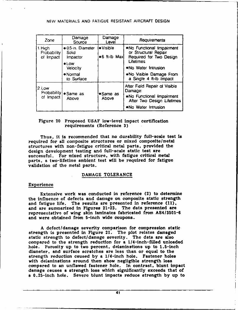
Zone Damage Damage ReuiremntsSource Level Requirements1. High *0.5-in. Diameter *Visible eNo Functional Impairment
Probability Solid or Structural Repairof Impact Impactor .6 ft-lb Max Required for Two Design
* Low LifetimesVelocity *No Water Intrusion
* Normal *No Visible Damage Fromto Surface a Single 4 ft-lb Impact
2. Low After Field Repair of VisibleProbability e Same as *Same as Damage:of Impact Above Above *No Functional Impairment
After Two Design Lifetimes*No Water Intrusion
Figure 20 Proposed U SAF low-level impact certificationrequirements (Reference 3)
Thus, it is recommended that no durability full-scale test Isrequired for all composite structures or mixed composite/metalstructures with non-fatigue critical metal parts, provided thedesign development testing and full-scale static test aresuccessful. For mixed structure, with fatigue critical metalparts, a two-lifetime ambient test will be required for fatiguevalidation of the metal parts.
DAMAGE TOLERANCE
Experience
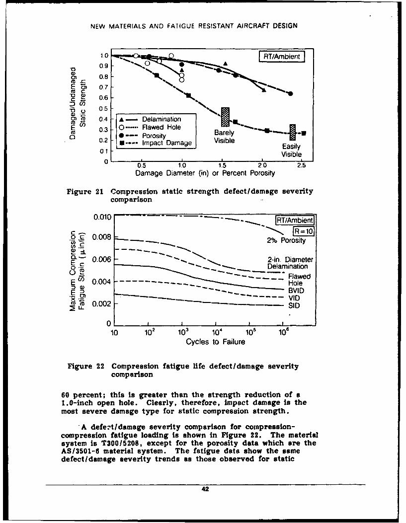
Extensive work was conducted in reference (2) to determinethe influence of defects and damage on composite static strengthand fatigue life. The results are presented in reference (11),and are summarized in Figures 21-23. The data presented arerepresentative of wing skin laminates fabricated from AS413501-6and were obtained from 5-inch wide coupons.
A defect/damage severity comparison for compression staticstrength is presented in Figure 21. The plot relates damagedstatic strength to defect/damage severity. The data are alsocompared to the strength reduction for a 1/4-inch-filled unloaded.hole. Porosity up to two percent, delaminations up to 1.5-inchdiameter, and surface scratches are less than or equal to thestrength reduction caused by a 1/4-inch hole. Fastener holeswith delaminations around them show negligible strength losscompared to an unflawed fastener hole. In contrast, blunt impactdamage causes a strength loss which significantly exceeds that ofa 0.25-inch hole. Severe blunt impacts reduce strength by up to
41
NEW MATERIALS AND FATIGUE RESISTANT AIRCRAFT DESIGN
1.0 FRT/Ambientj0.9 - A
CDo 0.8
MC
-C 0.6DCO-o 05"),
05 1 04 - - Delamination
E( 0.3 0 ...... Flawed Holeo 0--- Porosity Barely0.2 - .... Impact Damage VisibleEasily
01 Visible
0.5 1.0 1.5 2.0 2.5Damage Diameter (in) or Percent Porosity
Figure 21 Compression static strength defect/damage severity
comparison
0.010 . .. .-. IRT/Ambientl
o0 C 0.008W) .- 2% Porosity
....---c - 0.006 - 2-in. Diameter•c "- -- ___ Delamination
- " . FlawedE un 0.004 - ----- -.-.-.--.--.--- HoleE )- -Ho-- -- e B ID
5R--'-"- VID-M 0.002 - -u_ SID
0 I 3
10 102 103 04 105 106
Cycles to Failure
Figure 22 Compression fatigue life defect/damage severitycomparison
60 percent; this is greater than the strength reduction of a1.0-inch open hole. Clearly, therefore, impact damage is themost severe damage type for static compression strength.
*A defet/damage severity comparison for compression-compression fatigue loading is shown in Figure 22. The materialsystem is T300/5208, except for the porosity data which are theAS13501-6 material system. The fatigue data show the samedefect/damage severity trends as those observed for static
42
NEW MATERIALS AND FATIGUE RESISTANT AIRCRAFT DESIGN
0 .8 --- 1 0
0.6 Fatigue Threshold
"0 C FMax Cyclic/ FStatic Damaged
- 0.4 2% PorosityC 2-In. Dia. Delamination
E Flawed HoleZ 0.3 Barely Visible J BVID
Easily Visible Impact Damage VIDSevere I-SID
0 L
10 102 03 W04 101 106
Cycles to Failure
Figure 23 Normalized compression fatigue life defect/damageseverity comparison
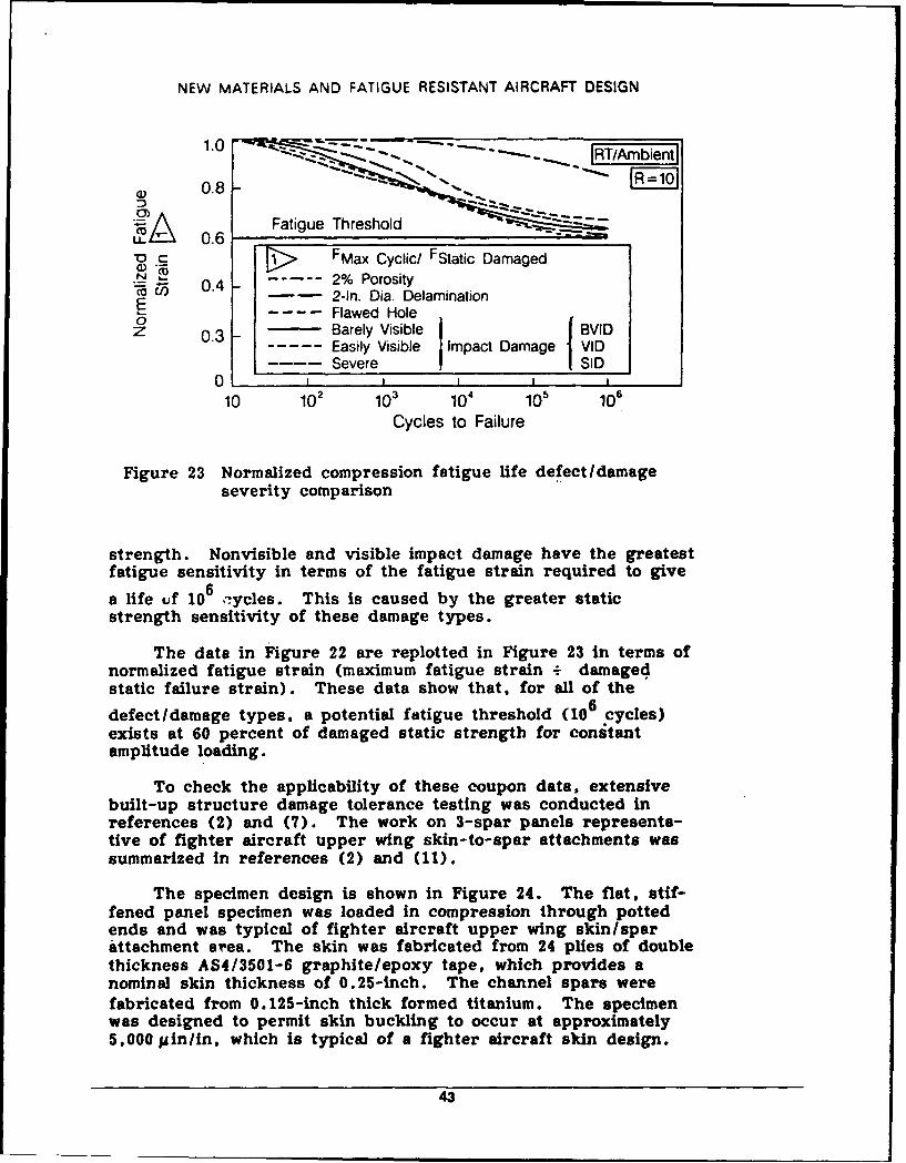
strength. Nonvisible and visible impact damage have the greatestfatigue sensitivity in terms of the fatigue strain required to give
a life uf 106 -ycles. This is caused by the greater staticstrength sensitivity of these damage types.
The date in Figure 22 are replotted in Figure 23 in terms ofnormalized fatigue strain (maximum fatigue strain + damagedstatic failure strain). These data show that, for all of the
defect/damage types, a potential fatigue threshold (106 cycles)exists at 60 percent of damaged static strength for constantamplitude loading.
To check the applicability of these coupon data, extensivebuilt-up structure damage tolerance testing was conducted inreferences (2) and (7). The work on 3-spar panels representa-tive of fighter aircraft upper wing skin-to-spar attachments wassummarized in references (2) and (11).
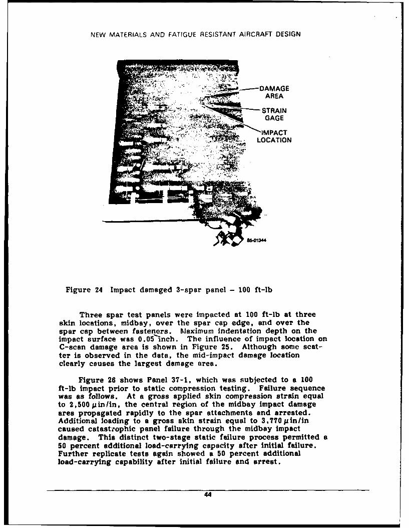
The specimen design is shown in Figure 24. The flat, stif-fened panel specimen was loaded in compression through pottedends and was typical of fighter aircraft upper wing skinlsparattachment area. The skin was fabricated from 24 plies of doublethickness AS4/3501-6 graphite/epoxy tape, which provides anominal skin thickness of 0.25-inch. The channel spars werefabricated from 0.125-inch thick formed titanium. The specimenwas designed to permit skin buckling to occur at approximately5,000 pin/in, which is typical of a fighter aircraft skin design.
43
NEW MATERIALS AND FATIGUE RESISTANT AIRCRAFT DESIGN
• ' : ' DAMAGE
AREA
' .' '-; , q STRAIN
LOCATION
Figure 24 Impact damaged 3-spar panel- 100 ft-lb
Three spar test panels were impacted at 100 ft-lb at threeskin locations, midbay, over the spar cap edge, and over thespar cap between fasteners. Maximum indentation depth on theimpact surface was 0.05 lnch. The influence of impact location onC-scan damage area is shown in Figure 25. Although some scat-ter is observed in the data, the mid-impact damage locationclearly couses the largest damage area.
Figure 26 shows Panel 37-1, which was subjected to a 100ft-lb impact prior to static compression testing. Failure sequencewas as follows. At a gross applied skin compression strain equalto 2,500 pin/in, the central region of the midbay impact damagearea propagated rapidly to the spar attachments and arrested.Additional loading to a gross skin strain equal to 3,770pin/incaused catastrophic panel failure through the midbay impactdamage. This distinct two-stage static failure process permitted a50 percent additional load-carrying capacity after initial failure.Further replicate tests again showed a 50 percent additionalload-carrying capability after initial failure and arrest.
44
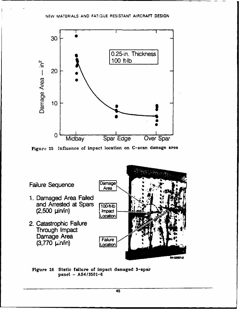
NEW MATERIALS AND FAT13UE RESISTANT AIRCRAFT DESIGN
I IT -
30
10.25-in. Thickness1100 ft-lb
120
E 10
01
Midbay Spar Edge Over SparFigure~ 25 onfluence of impact location on C-scan damage area
Failure Sequence
1. Damaged Area Failedand Arrested at Spars 10-ft-Ib(2,500 pin/in) Ipc
2. Catastrophic FailureThrough ImpactDamage Area Fjue'i(3,770 p~n/in)I cb
Figure 26 Static failure of impact damaged 3-sparpanel - AS4/3501-6
45
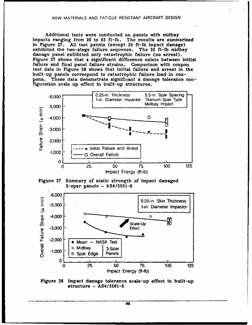
NEW MATERIALS AND FATIGUE RESISTANT AIRCRAFT DESIGN
Additional tests were conducted on panels with midbayimpacts ranging from 20 to 83 ft-lb. The results are summarizedin Figure 27. All test panels (except 20 ft-lb impact damage)exhibited the two-stage failure sequence. The 20 ft-lb midbaydamage panel exhibited only catastrophic failure (no arrest).Figure 27 shows that a significant difference exists between Initialfailure and final panel failure strains. Comparison with coupontest data in Figure 28 shows that initial failure and arrest in thebuilt-up panels correspond to catastrophic failure load in cou-pons. These data demonstrate significant a damage tolerance con-figuration scale up effect in built-up structures.
-6,000 0.5i.hckness 5.5-in. Spar Spacing I-1-in. Diameter Impactor Titanium Spar Type
- -5,000 Midbay Impact
C
=L -4,000 -
ca -3,000 - |_ .
a -2,000 -
U... - Initial Failure and Arrest-1.000 0 0 Overall Failure
0 1 1 j I ,0 25 50 75 100 125
Impact Energy (ft-lb)
Figure 27 Summary of static strength of impact damaged3-spar panels - AS41/3501-6
-6,000-6," 00.25-in. Skin Thickness
-5,000 -1-in. Diameter Impactor
C -4,000 - 0
05 Scale-Up-3,000 Effect
. -2,000 0 Mean - NASA Test
-,~0o Midbay 3-Spar> o Spar Edge Panels
0 i i i ,
0 25 50 75 100 125Impact Energy (ft-lb)
Figure 28 Impact damage tolerance scale-up effect in built-upstructure - AS4/3501-6
46
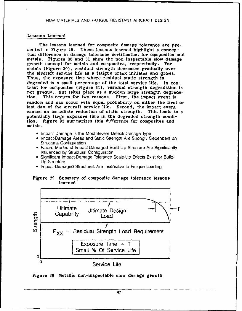
NEW MATERIALS AND FATIGUE RESISTANT AIRCRAFT DESIGN
Lessons Learned
The lessons learned for composite damage tolerance are pre-sented in Figure 29. These lessons learned highlight a concep-tual difference in damage tolerance certification for cQmposites andmetals. Figures 30 and 31 show the non-inspectable slow damagegrowth concept for metals and composites, respectively. Formetals (Figure 30), residual strength decreases gradually overthe aircraft service life as a fatigue crack initiates and grows.Thus, the exposure time where residual static strength isdegraded is a small percentage of the total service life. In con-trast for composites (Figure 31), residual strength degradation isnot gradual, but takes place as a sudden large strength degrada-tion. This occurs for two reasons. First, the impact event israndom and can occur with equal probability on either the first orlast day of the aircraft service life. Second, the impact eventcauses an immediate reduction of static strength. This leads to apotentially large exposure time in the degraded strength condi-tion. Figure 32 summarizes this difference for composites andmetals.
" Impact Damage Is the Most Severe Defect/Damage Type" Impact-Damage Areas and Static Strength Are Strongly Dependent on
Structural Configuration* Failure Modes of Impact-Damaged Build-Up Structure Are Significantly
Influenced by Structural Configuration" Significant Impact-Damage Tolerance Scale-Up Effects Exist for Build-
Up Structre" Impact-Damaged Structures Are Insensitive to Fatigue Loading
Figure 29 Summary of composite damage tolerance lessonslearned
Ultimate Ultimate Design TCapability Load
C:O /
U' PXX = Residual Strength Load Requirement
Exposure Time = TSmall % Of Service Life
0 Service Life
Figure 30 Metallic non-inspectable slow damage growth
47
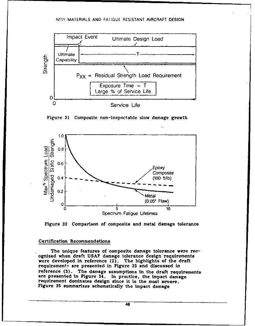
NFVV MATERIALS AND FAIIGUE RESISTANT AIRCRAFT DESIGN
Impact Event Ultimate Design Load/ /
Ultimate Tah Capability
PXX Residual Strength Load Requirement
Exposure Time = TLarge % of Service Life
000 Service Life
Figure 31 Composite non-inspectable slow damage growth
1.0-c
coa 0.8
00 1
E .2 0.6
F r 3CompositeU )0.4 (10 ib
0.2ZCU
(005 Flaw)
01 10 5 10
Spectrum Fatigue Lifetimes
Figure 32 Comparison of composite and metal damage tolerance
Certification Recommendations
The unique features of composite damage tolerance were rec-ognized when draft USAF damage tolerance design requirementswere developed in reference (2). The highlights of the draftrequirements, are presented in Figure 33 and discussed inreference (3). The damage assumptions in the draft requirementsare presented in Figure 34. In practice, the impact damagerequirement dominates design since it is the most severe.Figure 35 summarizes schematically the impact damage
48
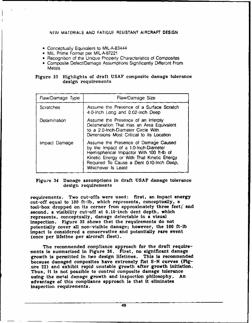
NEW MATERIALS AND FATIGUE RESISTANT AIRCRAFT DESIGN
" Conceptually Equivalent to MIL-A-83444" MIL Prime Format per MIL-A-87221" Recognition of the Unique Property Characteristics of Composites" Composite Defect/Damage Assumptions Significantly Differont From
Metals
Figure 33 Highlights of draft USAF composite damage tolerancedesign requirements
Flaw/Damage Type Flaw/Damage Size
Scratches Assume the Presence of a Surface Scratch4.0-Inch Long and 0.02-inch Deep
Delamination Assume the Presence of an InterplyDelamination That Has an Area Equivalentto a 2.0-Inch-Diameter Circle WithDimensions Most Critical to Its Location
Impact Damage Assume the Presence of Damage Causedby the Impact of a 1.0-Inch-DiameterHemispherical Impactor With 100 ft-lb ofKinetic Energy or With That Kinetic EnergyRequired To Cause a Dent 0.10-Inch Deep,Whichever Is Least
Figure 34 Damage assumptions in draft USAF damage tolerancedesign requirements
requirements. Two cut-offs were used: first, an impact energycut-off equal to 100 ft-lb, which represents, conceptually, atool-box dropped on its corner from approximately three feet;' andsecond, a visibility cut-off at 0.10-inch dent depth, whichrepresents, conceptually, damage detectable in a visualinspection. Figure 35 shows that the requirements do notpotentially cover all non-visible damage; however, the 100 ft-lbimpact is considered a conservative and potentially rare event(once per lifetime per aircraft fleet).
The recommended compliance approach for the draft require-ments is summarized in Figure 36. First, no significant damagegrowth is permitted in two design lifetimes. This is recommendedbecause damaged composites have extremely flat S-N curves (Fig-.ure 22) and exhibit rapid unstable growth after growth initiation.Thus, it Is not possible to control composite damage toleranceusing the metal damage growth and inspection philosophy. Anadvantage of this compliance approach is that it eliminatesinspection requirements.
49
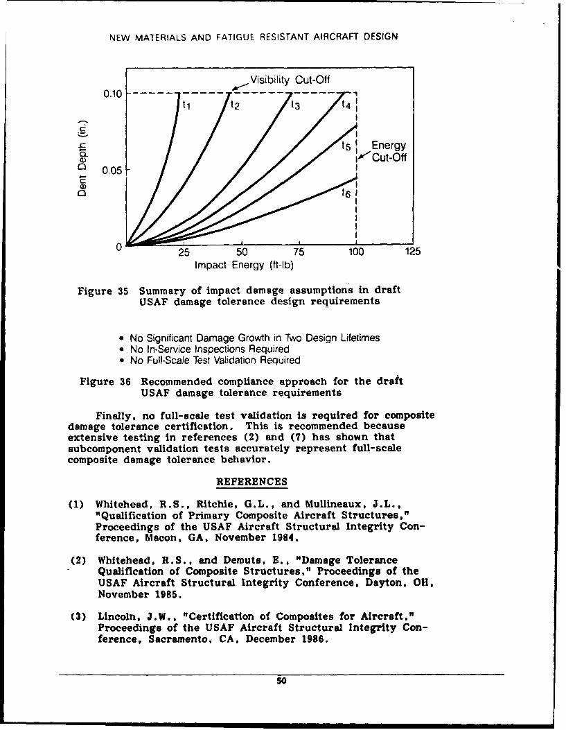
NEW MATERIALS AND FATIGUE RESISTANT AIRCRAFT DESIGN
- Visibility Cut-Off0.10 - - -- - -- - --
tl t2 t3
t s Energya~I) WCut-Off
C'0.05r
0 t6
0 25 50 75 100 125Impact Energy (ft-lb)
Figure 35 Summary of impact damage assumptions in draftUSAF damage tolerance design requirements
" No Significant Damage Growth in Two Design Lifetimes" No In-Service Inspections Required" No Fu)l-Scale Test Validation Required
Figure 36 Recommended compliance approach for the draftUSAF damage tolerance requirements
Finally, no full-scale test validation is required for compositedamage tolerance certification. This is recommended becauseextensive testing in references (2) and (7) has shown thatsubcomponent validation tests accurately represent full-scalecomposite damage tolerance behavior.
REFERENCES
(1) Whitehead, R.S., Ritchie, G.L., and Mullineaux, J.L.,"Qualification of Primary Composite Aircraft Structures,"Proceedings of the USAF Aircraft Structural Integrity Con-ference, Macon, GA, November 1984.
(2) Whitehead, R.S., and Demuts, E., "Damage ToleranceQualification of Composite Structures," Proceedings of theUSAF Aircraft Structural Integrity Conference, Dayton, OH,November 1985.
(3) Lincoln, J.W., "Certification of Composites for Aircraft,"Proceedings of the USAF Aircraft Structural Integrity Con-ference, Sacramento, CA, December 1986.
50
NEW MATERIALS AND FATIGUE RESISTANT AIRCRAFT DESIGN
(4) Whitehead, R.S., Ritchie, G.L., and Mulineaux, J.L.,"D" rability Certification of Fighter Aircraft Structures,"Proceedings of the 8th ICAF Symposium, Amsterdam,Holland, May 1981.
(5) Whitehead, R.S., and Deo, R.B., "A Building BlockApproach o Design Verification Testing of Primary CompositeStructure," Proceedings of the 24th AIAA/ASME/ASCEIAHSStructures, Structural Dynamics and Materials Conference,Lake Tahoe, NV, May 1983.
(6) Whitehead, R.S., Ritchie, G.L., and Mullineaux, J.L.,"Durability of Composites," presented at the 9th Mechanicsof Composites Review, Dayton, OH, October 1983.
(7) Hopper, J.M., Demuts, E., and Miliziano, G., "Damage Tol-erance Design Demonstration," Proceedings of the 25thAIAA/ASME/ ASCE/AHS Structures, Structural Dynamics andMaterials Conference, Palm Springs, CA, May 1984.
(8) Demuts, E., and Sharpe, P., "Toughened AdvancedCompositz- Structures," Proceedings of the 28thAIAA/ASME/ASCE/AHS Structures, Structural Dynamics andMaterials Conference, Monterey, CA, April 1987.
(9) Bohon, H.L., et al., "Ground Test Experience with LargeComposite Structures for Commercial Transports," NASA TM84627, March 1983.
(10) Whitehead, R.S., Kan, H.P., Cordero, R., and Saether, E.,"Certification Testing Methodology for Composite Structures,"NADC Contract No. N62269-C-0243, Final Report, October1986.
(11) Whitehead, R.S., "ICAF National Review," Pisa, Italy, May1985, pp. 10-26.
(12) Whitehead, R.S., "ICAF National Review," Ottawa, Canada,June 1987, pp. 10-18.
51
This page intentionally left blank.
52
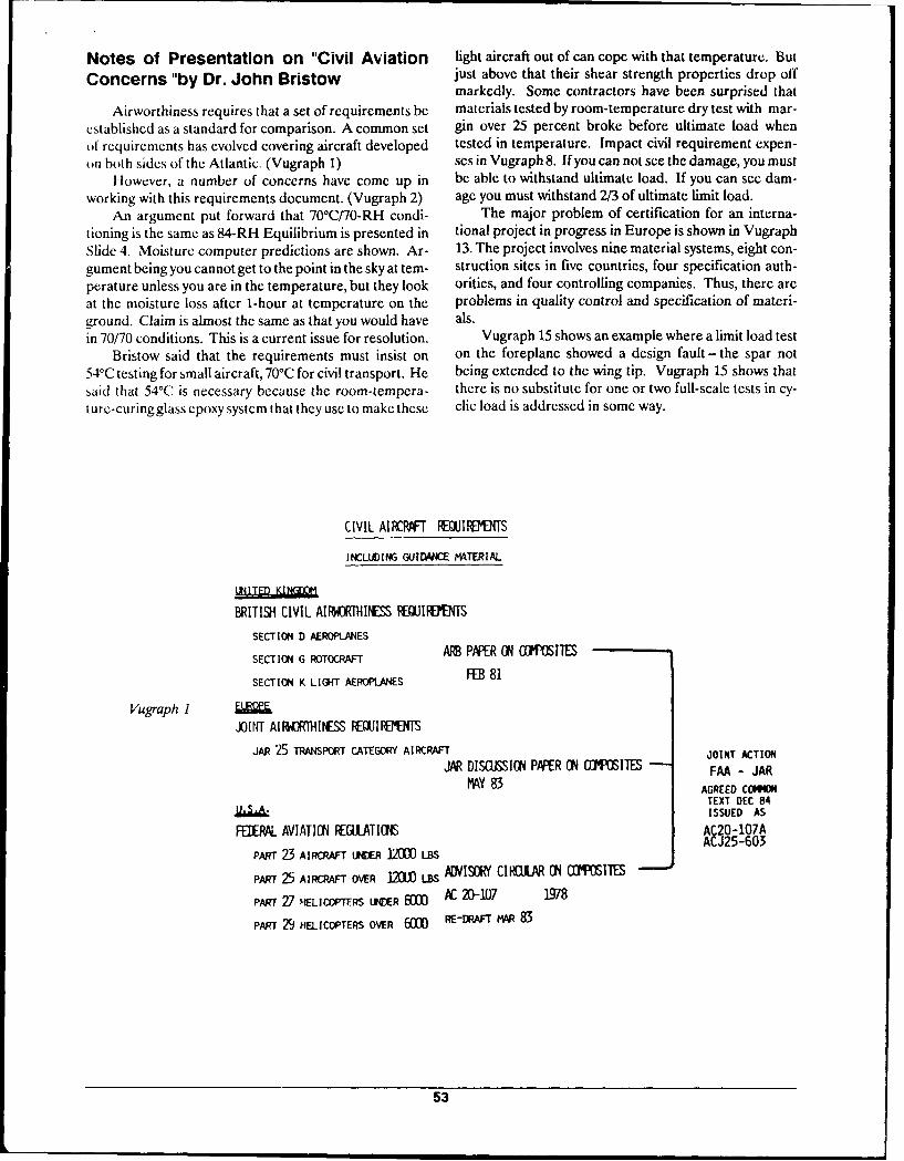
Notes of Presentation on "Civil Aviation light aircraft out of can cope with that temperature. But
Concerns "by Dr. John Bristow just abovc that their shear strength properties drop offmarkedly. Some contractors have been surprised that
Airworthiness requires that a set of requirements be materials tested by room-temperature dry test with mar-established as a standard for comparison. A common set gin over 25 percent broke before ultimate load whenof requirements has evolved covering aircraft developed tested in temperature. Impact civil requirement expen-of both sides of the Atlantic. (Vugraph 1) scs in Vugraph 8. If you can not see the damage, you must
However, a number of concerns have come up in be able to withstand ultimate load. If you can see dam-working with this requirements document. (Vugraph 2) age you must withstand 2/3 of ultimate limit load.
An argument put forward that 70°Ci70-RH condi- The major problem of certification for an interna-tioning is the same as 84-RH Equilibrium is presented in tional project in progress in Europe is shown in VugraphSlide 4. Moisture computer predictions are shown. Ar- 13. The project involves nine material systems, eight con-gument being you cannot get to the point in the sky at tem- struction sites in five countries, four specification auth-perature unless you are in the temperature, but they look orities, and four controlling companies. Thus, there areat the moisture loss after 1-hour at temperature on the problems in quality control and specification of materi-ground. Claim is almost the same as that you would have als.in 70/70 conditions. This is a current issue for resolution. Vugraph 15 shows an example where a limit load test
Bristow said that the requirements must insist on on the foreplane showed a design fault - the spar not54 0C testing for small aircraft, 70 0C for civil transport. He being extended to the wing tip. Vugraph 15 shows thatsaid that 54 0C is necessary because the room-tempera- there is no substitute for one or two full-scale tests in cy-ture-curingglass epoxy system that they use to make these clic load is addressed in some way.
CIVIL AIRCRAFT IEQUIlRTE3S
INCLUDING GUIDI4WE MATERIAL
BRITISH CIVIL AIIJRIIIINESS REQUIREMNS
SECTION D AEROPLANES
SECTION G ROTOCRAFT ARB PAPR ON (NWIVES
SECTION K LIGHT AEROPLANES FEB 81
Vugraph IJOIf AIP ATHIINESS REUIF1'TS
JAR 25 TRANSPORT CATEGORY AIRCRAFT JOINT ACTION
JAR DISMISIN PAPER C ( SITES FAA - JARMAY 83 AGREED COMMON
TEXT DEC 84ISSUED AS
FELR AVIATIH FEGUATII S AC20-1O7AACJ25-603
PART 23 AIRCRAFT LINER 120) LBS
PART 25 AIRCRAFT OVER 120 iBS A[VISORY CIRFULAR ( CO IIIES
PART 27 HELICOPTERS LtUR WM AC 20-1017 1978
PART 29 HELICOPTERS OVER 60 RE-DRAFT MAR 83
53
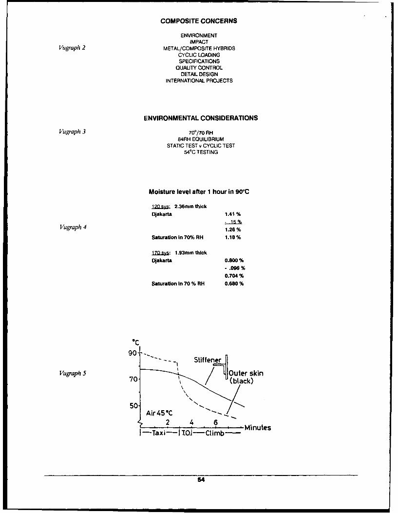
COMPOSITE CONCERNS
ENVIRONMENTIMPACT
Vugraph 2 METAL/COMPOSITE HYBRIDSCYCLIC LOADINGSPECIFICATIONS
QUALITY CONTROLDETAIL DESIGN
INTERNATIONAL PROJECTS
ENVIRONMENTAL CONSIDERATIONS
Vugraph 3 700/70 RH84RH EQUILIBRIUM
STATIC TEST v CYCLIC TEST540C TESTING
Moisture level after 1 hour in 900C
120 2.36mm thick
Djakarta 1.41 %
Vugraph 4 1.26%
Saturation In 70% RH 1.18%
170.sy.: 1.93mm thick
Djakarta 0.800%- .096%0.704%
Saturation in 70 % PH 0.680%
0C
90- - -I Stif fener
Vugraph S1outer skin70- ,(black)
50 ''5 Air45 C ., . ...
2 4 MiueI -Taxi-! O.1- Climb- Minutes
54
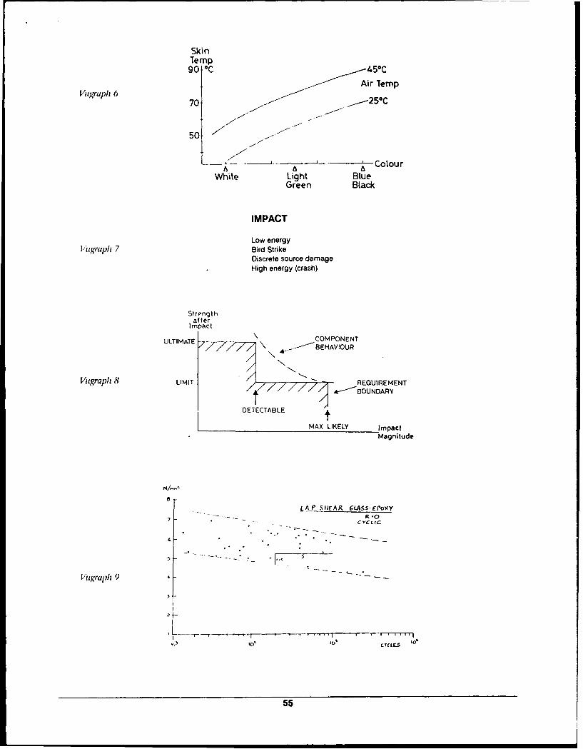
SkinTemp90 C 450C
ua 6Air Temp
50
Colour6 6 6
White Light BlueGreen Black
IMPACT
Low energy
[ugraph 7 Bird StrikeDiscrete source damage
High energy (crash)
Strengthafter
ImpactULTIMATE COMPONENT
U 7LTIM 777 \ -- BEHAVIOUR
Vugraph 8 LIMIT REQUIREMENT11AIIIIII/ ; -- BOUNDARY
DETECTABLE N
MAX LIKELY ImpactMagnitude
8
LAP S1EAR GLAS.-EPoy
7 RCYCLIC
V/tgraph 9•
LYCLES
55
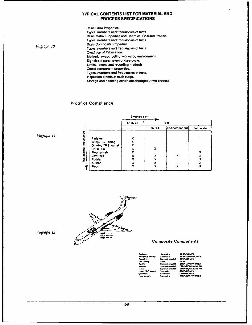
TYPICAL CONTENTS LIST FOR MATERIAL ANDPROCESS SPECIFICATIONS
Basic Fibre Properties.Types, numbers and frequencies of tests.Basic Matrix Properties and Chemical Characterization.Types, numbers and frequencies of tests.
Vugraph 10 Basic Composite PropertiesTypes, numbers and frequencies of tests.Condition of Fabrication.Method, lay-up, tooling, workshop environment.Significant parameters of cure cycle.Limits, ranges and recording methods.Cured component properties.Types, numbers and frequencies of tests.Inspection criteria at each stage.Storage and handling conditions throughout the process.
Proof of Compliance
Emphasis on:
Analysis Test
Detail Subcomponent Ful-scale
Vugraph 11 II Radome X& Wing/fus. fairing X.~0. wing TR.E. panel X
C Dorsal fin X XI Floor panels X X
S Cowlings X X x XU Rudder X X X
Aileron X X XFlops X X X X
Vrgraph 12
Composite Components
Sandwd, AIRP/O&ACXWW.../14 WM,," $ S~d h AFRP/GFRP/rEOMSX0.81a 16. Sandwich/sold AFOP/HOMIX
T~i 1.1' ..id A.M CFRP/A P"'.d" so'"ndleow CF PRPMIMI lg
'IPeS*,.Wkh/sM CF/11,NOMXMrIAtW's ?R t -ft p.w . ."wcI AfR/OA1IEX
Cw4Ii'9 39.d4h CFUIP/NOMSKto., '..I, sendl~m Cf$1PfGFfP/NOMfX
58
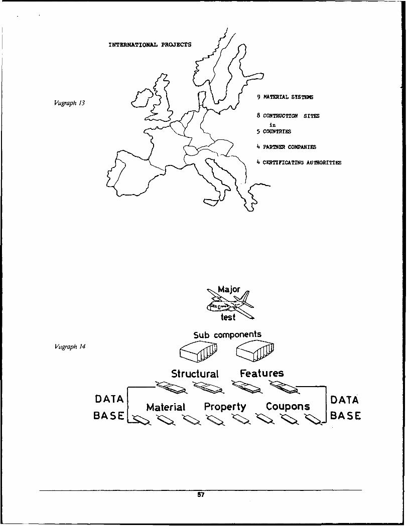
INTERNATIONAL PROJECTS
9 MATERIAL SYSTEI
Vugrapi: 13
8 CONTRUCTION SITES
in5 couNTRrls
4 PARIIER CONPANiEs
4 CERTIFICATING AUTHORITIES
test
Sub componentsVugraph 14 P P
Structural Features
DAI"AI Material Property Coupons DATABASE BASE
57
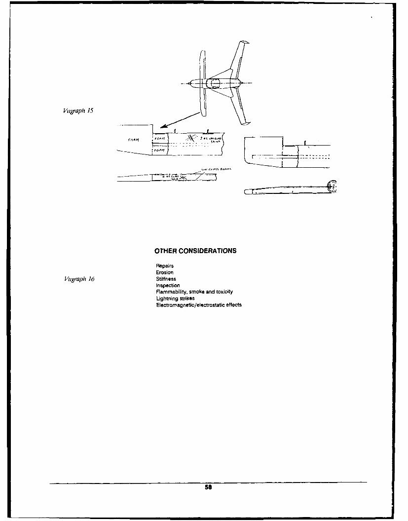
Vugrapl 15
FOA'1
OTHER CONSIDERATIONS
RepairsErosion
Vigraph 16 StiffnessInspectionFlammability, smoke and toxicityLightning strikesElectromagnetic/electrostatic effects
58
I I I
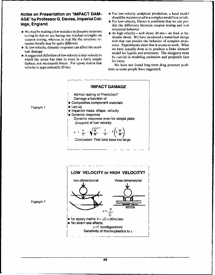
Notes on Presentation on "IMPACT DAM- * For low-velocity analytical prediction, a local model
AGE" by Professor G. Davies, Imperial Col- should be incorporated in a complex model test article.E For low-velocity, Davies is confident that we can pre-
lege, England dict the difference between coupon testing and realstructural behavior.
SWetmay be making a few mistakcs in dynamic response o At high velocity - well above 20 m/s - we look at hy-testing in that we are basing our residual strengths on draulic shock. We have produced a numerical designcoupon testing, whereas in real life the structure re tool that can predict the behavior of complex struc-sponse locally may be quite different. ue.Eprmnsso hti em owr.Wa
" At low velocity, dynamic response can affect the resul- tures. Experiments show that it seems to work. Whatwe have actually done is to produce a finite elementtant damage. model for liquids and structures. The designers must
* A suggested definition of low velocity is that velocity in be careful in modeling cavitation and projectile face
which the strain has time to react in a fairly simple for entry.
fashion, not necessarily linear. For epoxy matrix that We ent fteveloityis pprximaely20 /s.We have not found long-term drag pressure prob-
lems as some people have suggested.
IMPACT DAMAGE
Ad-hoc testing or Prediction?Damage a function of:
* Composites component materialsVugraph I Io Lay-up
e Impactor mass, shape, velocity* Dynamic response
Dynamic response even for simple plate(coupon) at low velocity:
=v M . .f(tM'_
Conclusion: Test data base too large.
LOW VELOCITY or HIGH VELOCITY?
two-dimensional three-dimensional
Vugraph 2 lEIEV
C" for epoxy matrix V= eC =20m/sec" No strain rate effects.
=f (configuration)Sensitivity of thermoplastics to e
59
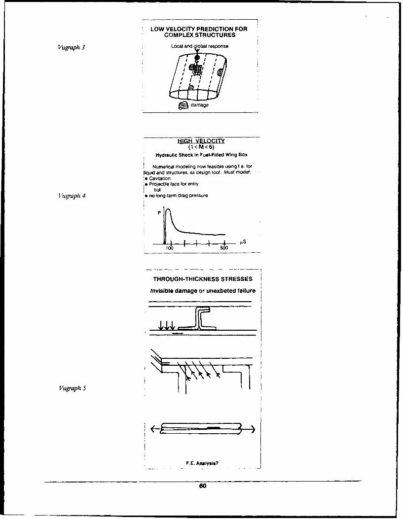
LOW VELOCITY PREDICTION FOR
COMPLEX STRUCTURES
Vugraph 3 Local and lobal response
I ; I.T. ;
d damage
HIGH VELOCI1(1<M<6)
Hydraulic Shock in Fuel-Filled Wing Box
Numerical modeling now feasible using fe. forliquid and structures, as design tool. Must model:. Cavitation* Projectile face for entry
butl1ugraph 4 * no long-term drag pressure
* P
100 500
THROUGH-THICKNESS STRESSES
Invisible damage or unexbeted failure
Vugraph 5
F.E. Analysis?
60
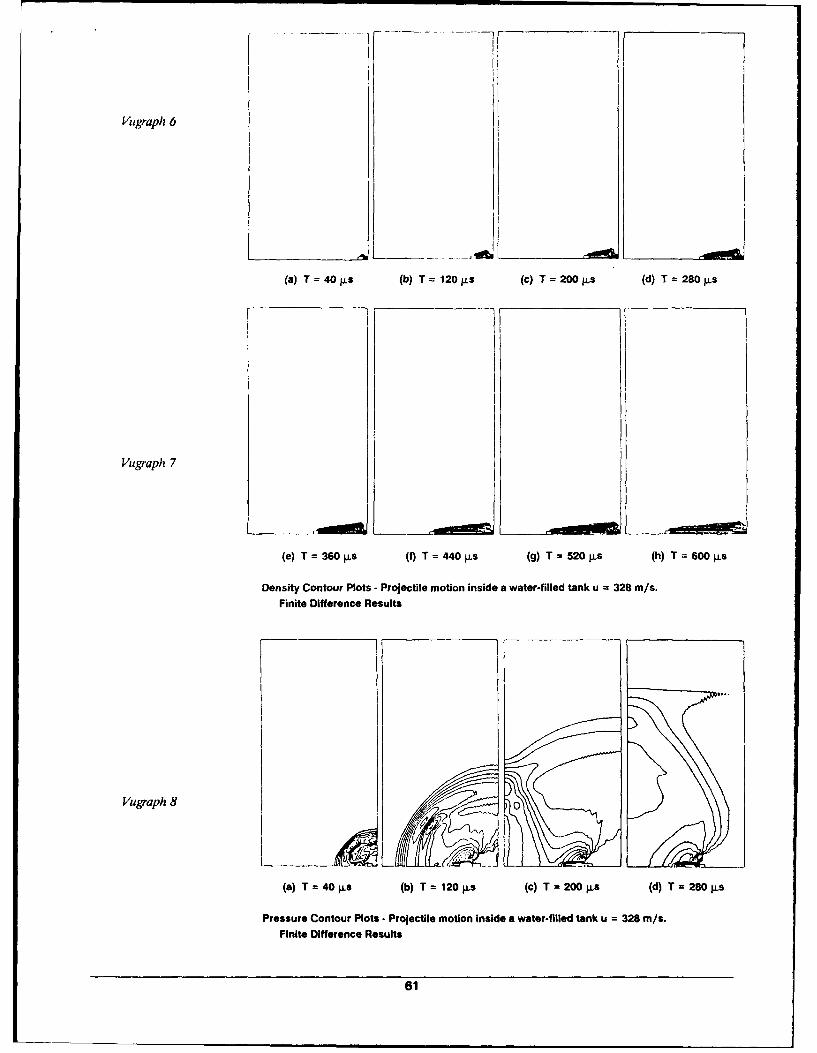
Vugraph 6
(a) T= 40 .s (b) T= 120 s (c) T= 200 s (d) T 280 ps
Vugraph 7
(e) T = 360s (t) T = 440 pLs (g) T = 520 pLs (h) T =600 s
Density Contour Plots -Projectile motion inside a water-filled tank u 328 m/s.Finite Difference Results
Vugraph 8 0
(a) T =40 pLs (b) T= 120ps (c) T =200 I.S (d) T= 280 Lps
Pressure Contour Plots - Projectile motion inside a water-filled tank u = 328 M/s.Finite Difference Results
61
This page intentionally left blank
62
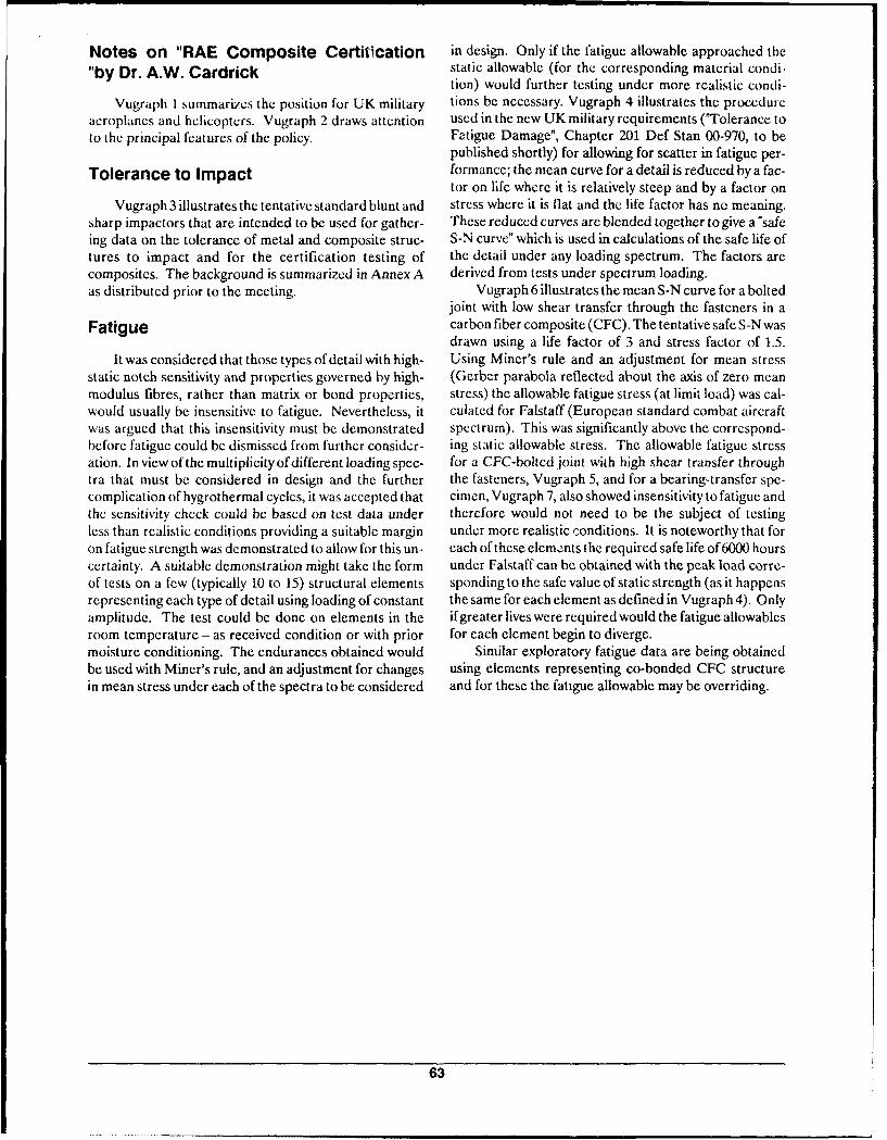
Notes on "RAE Composite Certification in design. Only if the fatigue allowable approached the
"by Dr. A.W. Cardrick static allowable (for the corresponding material condi-tion) would further testing under more realistic condi-
Vugraph I summarizes the position for UK military tions be necessary. Vugraph 4 illustrates the procedureaeroplancs and helicopters. Vugraph 2 draws attention used in the new UK military requirements ("Tolerance toto the principal features of the policy. Fatigue Damage", Chapter 201 Def Stan 00-970, to be
published shortly) for allowing for scatter in fatigue per-Tolerance to Impact formance; the mean curve for a detail is reduced by a fac-
tor on life where it is relatively steep and by a factor onVugraph 3 illustrates the tentative standard blunt and stress where it is flat and the life factor has no meaning.
sharp impactors that are intended to be used for gather- These reduced curves are blended together to give a "safeing data on the tolerance of metal and composite struc- S-N curve" which is used in calculations of the safe life oftures to impact and for the certification testing of the detail under any loading spectrum. The factors arecomposites. The background is summarized in Annex A derived from tests under spectrum loading.as distributed prior to the meeting. Vugraph 6 illustrates the mean S-N curve for a bolted
joint with low shear transfer through the fasteners in aFatigue carbon fiber composite (CFC). The tentative safe S-N was
drawn using a life factor of 3 and stress factor of 1.5.It was considered that those types of detail with high- Using Miner's rule and an adjustment for mean stress
static notch sensitivity and properties governed by high- (Gerber parabola reflected about the axis of zero meanmodulus fibres, rather than matrix or bond properties, stress) the allowable fatigue stress (at limit load) was cal-would usually be insensitive to fatigue. Nevertheless, it culated for Falstaff (European standard combat aircraftwas argued that this insensitivity must be demonstrated spectrum). This was significantly above the correspond-before fatigue could be dismissed from further consider- ing static allowable stress. The allowable fatigue stressation. In view of the multiplicity of different loading spec- for a CFC-boltcd joint with high shear transfer throughtra that must be considered in design and the further the fasteners, Vugraph 5, and for a bearing-transfer spe-complication of hygrothermal cycles, it was accepted that cimen, Vugraph 7, also showed insensitivity to fatigue andthe sensitivity check could be based on test data under therefore would not need to be the subject of testingless than realistic conditions providing a suitable margin under more realistic conditions. It is noteworthy that foron fatigue strength was demonstrated to allow for this un- each of these elements the required safe life of 6000 hourscertainty. A suitable demonstration might take the form under Falstaff can be obtained with the peak load corre-of tests on a few (typically 10 to 15) structural elements sponding to the safe value of static strength (as it happensrepresenting each type of detail using loading of constant the same for each element as defined in Vugraph 4). Onlyamplitude. The test could be done on elements in the if greater lives were required would the fatigue allowablesroom temperature - as received condition or with prior for each element begin to diverge.moisture conditioning. The endurances obtained would Similar exploratory fatigue data are being obtainedbe used with Miner's rule, and an adjustment for changes using elements representing co-bonded CFC structurein mean stress under each of the spectra to be considered and for these the fatigue allowable may be overriding.
63
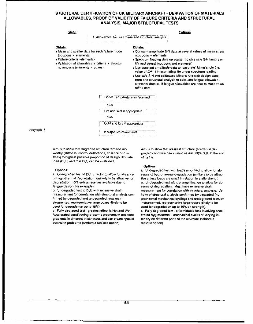
STUCTURAL CERTIFICATION OF UK MILITARY AIRCRAFT - DERIVATION OF MATERIALSALLOWABLES, PROOF OF VALIDITY OF FAILURE CRITERIA AND STRUCTURAL
ANALYSIS, MAJOR STRUCTURAL TESTS
Stc aguei lowables, failure criteria and structural analysis
Obtain: Obtain:" Mean and scatter data for each failure mode . Constant amplitude S-N data at several values of mean stress
(coupons + elements) (coupons + elements)" Failure criteria (elements) w Spectrum loading data on scatter (to give safe S-N factors on" Validation of allowables + criteria + structu- life and stress) (coupons and elements)
ral analysis (elements + boxes) a Use constant amplitude data to "calibrate" Miner's rule (i.e.value of J-a ) in estimating life under spectrum loading.
a Use safe S-N and calibrated Miner's rule with design spec-trum and structural analysis to calculate fatigue allowablestress for details. If fatigue allowables are near to static valuerefine data.
r---hom Temperature as received I
plus
Hot and Wet if appropriate
plus
Cold and Dry if appropriate
VMgraph 1 F 2 Major Structural tests
Aim is to show that degraded structure remains air- Aim is to show that weakest structure (scatter) in de-worthy (stiffness, control deflections, absence of dis- graded condition can sustain at least 80% DUL at the endtress) to highest possible proportion of Design Ultimate of its life.load (DUL) and that DUL can be sustained.
Options:Options: a. Undegraded test with loads amplified to allow for ab-
a. Undegraded test to DUL x factor to allow for absence sence of hygrothermal degradation (unlikely to be attrac-of hygrothermal degradation (unlikely to be attracive for tive unless loads are small in relation to static strength).degradation > 5% unless reserves available due to b. Undegraded test without amplification to allow for ab-fatigue design, for example). sence of degradation. Must have extensive strainb. Undegraded test to DUL with extensive strain measurement for correlation with structural analysis. Va-measurement for correlation with structural analysis con- lidity of structural analysis confirmed by degraded (hy-firmed by degraded and undegraded tests on in- grothermal-mechanical cycling) and undegraded tests onstrumented, representative large boxes (likely to be instrumented, representative large boxes (likely to beused for degradation up to 15%). used for degradation up to 15% on strength).c. Fully degraded test - greatest effect is Hot and Wet. c. Fully degraded test -a formidable task involving accel-Accelerated conditioning presents problems of moisture erated hygrothermal - mechanical cycles of varying in-gradients in different thicknesses and can create special tensity on different parts of the structure (seldom acorrosion problems (seldom a realistic option), realistic option).
64
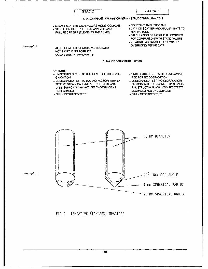
STATIC - FATIGUE
1. ALLOWABLES, FAILURE CRITERIA 7 STRUCCTURAL ANALYSIS
. MEAN & SCATTER EACH FAILURE MODE (COUPONS) a CONSTANT AMPLITUDE S-Na VALIDATION OF STRUCTURAL ANALYSIS AND * DATA ON SCATTER AND ADJUSTMENTS TO
FAILURE CRITERIA (ELEMENTS AND BOXES) MINER'S RULEm CALCULATION OF FATIGUE ALLOWABLES
FOR COMPARISON WITH STATIC VALUESa IF FATIGUE ALLOWABLE POTENTIALLY
Vugraph 2 ALL ROOM TEMPERATURE/AS RECEIVED OVERRIDING REFINE DATA
HOT & WET IF APPROPRIATECOLD & DRY, IF APPROPRIATE
2. MAJOR STRUCTURAL TESTS
OPTIONS:" UNDEGRADED TEST TO DUL X FACTOR FOR NO DE- a UNDEGRADED TEST WITH LOADS AMPLI-
GRADATION FIED FOR NO DEGRADATION" UNDEGRADED TEST TO DUL (NO FACTOR) WITH EX- w UNDEGRADED TEST (NO DEGRADATION
TENSIVE STRAIN GAUGING & STRUCTURAL ANA- FACTOR) WITH EXTENSIVE STRAIN GAUG-LYSIS SUPPORTED BY BOX TESTS DEGRADED & ING, STRUCTURAL ANALYSIS, BOX TESTSUNDEGRADED DEGRADED AND UNDEGRADED
" FULLY DEGRADED TEST a FULLY DEGRADED TEST
50 mm DIAMETER
Vugraph 3 H 900 INCLUDED ANGLE
I1- 1n SPHERICAL RADIUS
25 uni SPHERICAL RADIUS
FIG 2 TENTATIVE STANDARD IMPACTORS
65
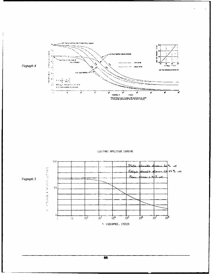
fl 13;k 1r* r130 F. ~.1.V f
JVigraph 4 "SS~ F M"I-
sIR o sooocvim mmim0i
G- 1 - W' 1!--
UQ (. N C~l
M M OF SI QZ( ORA 101 "!~ k ~~MIS flATS
WMICH 540 UTMIS OF300 FA*5 TO VAI SMG!II 501
CONSTANT AMPLITUDE LOADING
Vugrapli 5 m. t'.- 7
Io i10 01 0 305 16 6
ff EUDBURPNCE. CYCLES
66
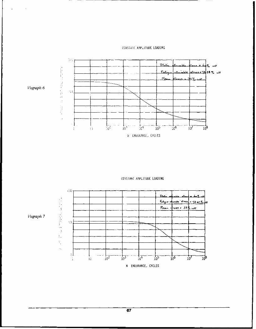
CONSIANI AMPLITUDE LOADING
Vugraph 6
5 1 0 1 io181u 10 1O 0 i00
SENDURANCE, CYCtES
CONSTANT AMPLITUDE LOADING
Vugraph 7 __,
ic i0'i2
N ENDURANCE, CYCLES
67
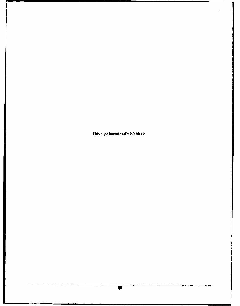
This page intentionally left blank
66
The effect of observed climaticconditions on the moistureequilibrium level of fibre-reinforced plastics?A COLLINGS
(Royal Aircraft Establishment UK
Calculations have been made to determine the moisture absorptionbehaviour of fibre- reinforced epoxy-matrix composites after exposureto prescribed outdoor climatic environments. A review of world-widemeteorological conditions has been made and six environments werechosen to represent a variety of regions. The results suggest that thelevel of moisture currently assumed to be absorbed by a compositeduring the service life of an aircraft is too low and that a much highervalue should be used. Since the absorption kinetics of resin matricesdiffer widely and also change with physical ageing, the validity ofspecifying a moisture level to define the degree of environmentaldegradation in structural assessment is questioned. An alternativecriterion, a constant relative humidity environment that will produce arepresentative moisture level in all parts of the structure and for allmatrices currently in use, is proposed. Using this philosophy it issuggested that the world-wide worst environment might best besimulated by a constant humidity of 84%.
Key words: composite materials; water-absorption tests;environmental testing: climatic conditions; relative humidity carbonfibres; epoxy resins
The use of fibre-reinforced plastics (FRP) in aircraft The need to secure agreement on an internationalstructures is increasing as new generations of aircraft collaborative project has led to a re-assessment of thetake advantage of their attractive structural properties. validity of this value. A survey has therefore been madeHowever a disadvantage is their readiness to absorb of world-wide climatic records to select the temperaturemoisture, with consequent degradation' of those and humidity data necessary for the calculation ofstrength properties of the composite which are matrix moisture equilibrium evels for FRP. Six locations havedependent. particularly at high temperatures. Allow- been chosen tG represent temperate regions. such asance has to be made for this degradation effect during UK and mainland Europe, hot humid coastal equa-the airworthiness substantiation, either by the use of torial areas and M;ddle East regions with variableextra strength factors in design or by testing to seasonal climates.establish the true srength of components in a degra-ded state. The degradation that these structures will see The effects of these climates on total moisture levelin service is linked with the level of moisture absorbed and distribution are reported here for variousduring the service life of the component. usually about thicknesses of laminate freshly made from carbon25 years, Thus there is a need for a realistic assessment fibre-reinforced plastic (CFRP) (XAS/913 carbon fibre./to be made of the amount of moisture likely to be epoxy resin system). These moisture levels are thenabsorbed during the service life of an aircraft (currently used in the reverse calculation to give the steady-stateassumed to be 1.0%). and the necessary artificial ageing artificial ageing conditions which will simulate theto reproduce this moisture levels typical of natural climates
69
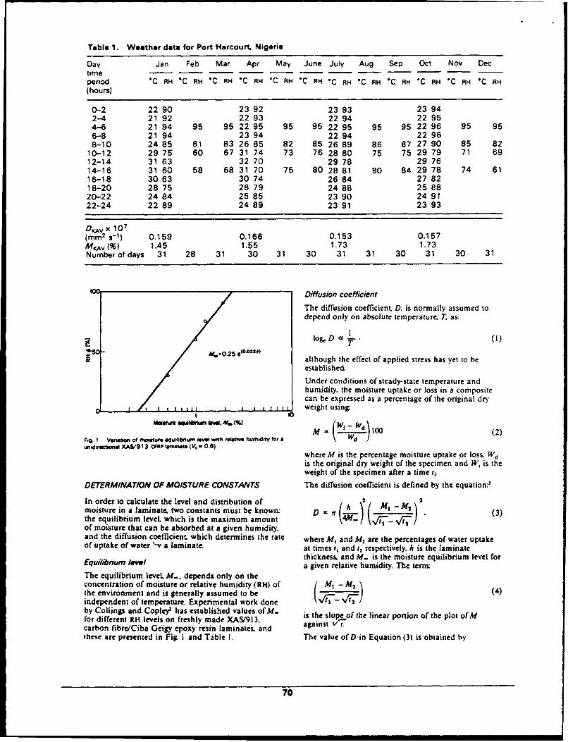
Table 1. Weather date for Port Harcourt. Nigeria
Day Jan Feb Mar Apr May June July Aug Sep Oct Nov Dectimeperiod *C RH *C RH *C RH "C RH *C RH *C RH -C RH -C RH *C RH *C RH *C RH *C RH(hours)
0-2 22 90 23 92 23 93 23 942-4 21 92 22 93 22 94 22 954-6 21 94 95 95 22 95 95 95 22 95 95 95 22 96 95 956-8 21 94 23 94 22 94 22 968-10 24 85 81 83 26 85 82 85 26 89 86 87 27 90 85 82
10-12 29 75 60 67 31 74 73 76 28 80 75 75 29 79 71 6912-14 31 63 32 70 29 78 29 7614-16 31 60 58 68 31 70 75 80 28 81 80 84 29 78 74 6116-18 30 63 30 74 26 84 27 8218-20 28 75 28 79 24 88 25 8820-22 24 84 25 85 23 90 24 9122-24 22 89 24 89 23 91 23 93
DKv x 107(mm 2 s- 1) 0.159 0.166 0.153 0.157M v () 1.45 1.55 1.73 1.73Number of days 31 28 31 30 31 30 31 31 30 31 30 31
Diffusion coefficient
The diffusion coefficient. D. is normally assumed todepend only on absolute temperature. T as:
~logD a , l
Aalthough the effect of applied stress has yet to be
established
Under conditions of steady-state temperature andhumidity, the moisture uptake or loss in a compositecan be expressed as a percentage of the original dry
1 1, t if , weight usingt 10
M =1011100 (2
R% I Vanrm of mo dstue euig u i wnh nitAVfor Mha (Wi - 1(2)
unw.dirctona1 XA&913 cFRPiamenst. V,-0.6)where M is the percentage moisture uptake or loss. Wdis the original dry weight of the specimen and Wi is theweight of the specimen after a time t,
DETERMINATION OF MOISTURE CONSTANTS The diffusion coefficient is defined by the equation:'
In order to calculate the level and distribution of 2 2moisture in a laminate, two constants must be known: D = ff h I M- M 2 (3)the equilibrium level, which is the maximum amountof moisture that can be absorbed at a given humidity.and the diffusion coefficient, which determines the rate where M, and M, are the percentages of water uptakeof uptake of water '-v a laminate, at times r, and t, respectively. h is the laminate
thickness, and M. is the moisture equilibrium level forEquilibrium level a given relative humidity. The term:
The equilibrium leveL M.. depends only on theconcentration of moisture or relative humidity (RH) of / Mt - M2the environment and is generally assumed to be/ / (4)independent of temperature. Experimental work done (VI-V tI2-by Collings and Copley' has established values of M. ifor different RH levels on freshly made XAS/913. is the slpeof the linear porion of the plot of Mcarbon fibre/Ciba Geigy epoxy resin laminates, and against t.these are presented in Fig I and Table I. The value of D in Equation (3) is obtained by
70
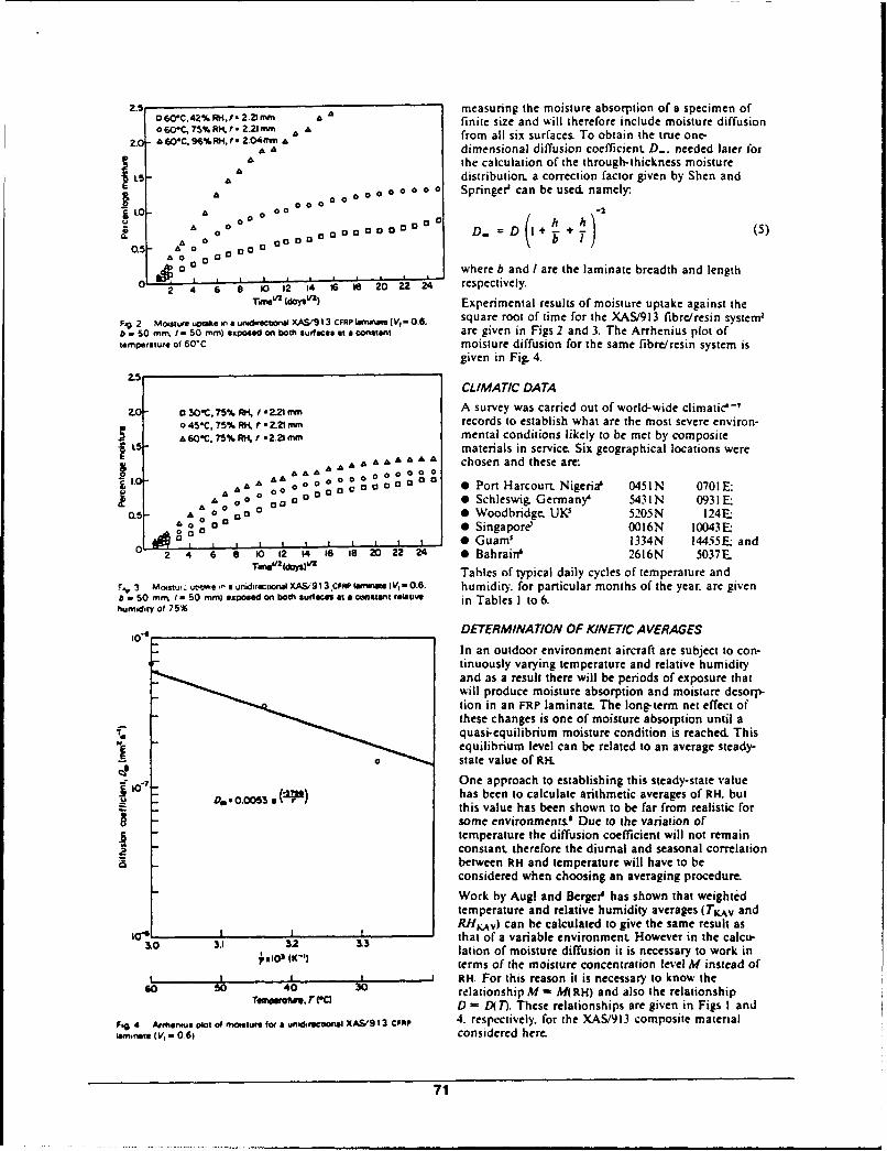
. 060C.42%RM.l/2.2mm measuring the moisture absorption of a specimen ofo 60*r,75% f 2.21 mm Afinite size and will therefore include moisture diffusiono60C, 96%RH, 1 2.011, A " from all six surfaces To obtain the true one-2.0 AEOC, 96%RI, t, 2.04mm,,
= A dimensional diffusion coefficienL D.. needed later forA the calculation of the through-thickness moisture
L5 A "distribution, a correction factor given by Shen and
A0 0 0 0 0 0 0 Springer' can be used. namely.
l A 00
0.5- a0 000 000-
A. = A 0an0000000 o D. =D 1+ .~ (5)
ao Do o
a where b and Iare the laminate breadth and length
.0 24 14 i le o20 24 respectively-Trmv 2 tdoysv) Experimental results of moisture uptake against the
Fg.2 Motsfueup keinaunr, cl OnIXAS/913CFRPLI~mfbtfVf,-6. square root of time for the XAS/913 fibre/resin system'b - 50 m,. I - 50 mm) exposed on both surfaces at a constant are given in Figs 2 and 3. The Arrhenius plot oftemperatue of 60'C moisture diffusion for the same fibre/resin system is
given in Fi& 4.
2.5
CLIMATIC DATA
.0 30C,75% t i2.21 mm A survey was carried out of world-wide climatic'-7
o 45*C. 75% A*4 f .2 tmm records to establish what are the most severe environ-A 60C. 75% RK f .. 21mm mental conditions likely to be met by composite
L materials in service. Six geographical locations wereL A 0000 chosen and these are:
.0A A 0 0 000 0 0 Port H-arcourt. Nigeria' 0451 N 0701 EA 0 Schleswig. Germany' 5431 N 0931E;
A . 0 0 0 Woodbridge. UK' 5205N 124E1o 00 0 Singapore 0016N 10043 1E-,Og0
I I t 0 Guam' 1334N 14455Eand
2 4 6 8 10 12 14 ts 1 2 22 24 * Bahrain' 2616N 5037ETme (days)" Tables of typical daily cycles of temperature and
F.3 Mostwurut lunidraciblXA&93.CFAPaiIUfatV,=0. 6 . humidity. for particular months of the year. are givena -50 mrm. / -so mm) .xpose on both suraces at a cmnt tue, in Tables I to 6.humidity of 75%
_ _o_ _ _DETERMINATION OF KINETIC AVERAGES
In an outdoor environment aircraft are subject to con-r tinuously varying temperature and relative humidity
and as a result there will be periods of exposure thatwill produce moisture absorption and moisture desorp-tion in an FRP laminate The long-term net effect ofthese changes is one of moisture absorption until aquasi-equilibrium moisture condition is reached Thisequilibrium level can be related to an average steady-
0 state value of RHOne approach to establishing this steady-state value
, "* • ( ) has been to calculate arithmetic averages of RH. butthis value has been shown to be far from realistic forsome environments.$ Due to the variation oftemperature the diffusion coefficient will not remainconstant. therefore the diurnal and seasonal correlationbetween RH and temperature will have to beconsidered when choosing an averaging procedure.
Work by Augl and Berger' has shown that weightedtemperature and relative humidity averages (TKAv andRHKv) can be calculated to give the same result as
&O0 3I1 & that of a variable environment. However in the calcu-lation of moisture diffusion it is necessary to work in
?a 1(K-11 terms of the moisture concentration level M instead of| I -_ __ RH. For this reason it is necessary to know the
60 so 40 30 relationship M ex M(RH) and also the relationshipTemrw , rem D - D(T). These relationships are given in Figs I and
Fig 4 Armeuit im of moitr fr" uniirctiall XAS/913 CFRP 4. respectively, for the XAS/913 composite materialism,.ve (V, - 06) considered here.
71
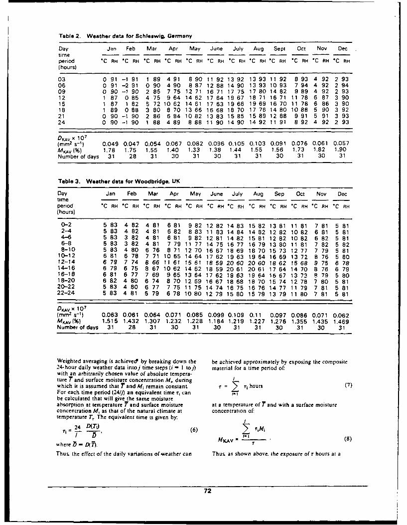
Table 2. Weather data for Schleswig. Germany
Day Jan Feb Mar Apr May June July Aug Sept Oct Nov Dectimeperiod 'C RH *C RH *C RH 'C RH *C RH *C RH *C RH *C RH 'C RH 'C RH -C RH "C RH(hours)
03 0 91 -1 91 1 89 4 91 8 90 11 92 13 92 13 93 11 92 8 93 4 92 2 9306 0 91 -2 91 0 90 4 90 8 87 12 88 14 90 13 93 10 93 7 94 4 92 2 9409 0 90 -1 90 2 85 7 75 12 71 16 71 17 75 17 80 14 82 9 89 4 92 2 9312 1 87 0 85 4 75 9 64 14 62 17 64 19 67 18 71 16 71 11 78 6 87 3 9015 1 87 1 82 5 72 10 62 14 61 17 63 19 66 19 69 16 70 11 78 6 86 3 9018 1 89 0 88 3 80 8 70 13 66 16 68 18 70 17 76 14 80 10 88 5 90 3 9221 0 90 -1 90 2 86 6 84 10 82 13 83 15 85 15 89 12 88 9 91 5 91 3 9324 0 90 -1 90 1 88 4 89 8 88 11 90 14 90 14 92 11 91 8 92 4 92 2 93
DKAv x 107(mm 2 s- 1) 0.049 0.047 0.054 0.067 0.082 0.096 0.105 0.103 0.091 0.076 0.061 0.057Mv (%) 1.78 1.75 1.55 1.40 1.33 1.38 1.44 1.55 1.56 1.73 1.82 1.90Number of days 31 28 31 30 31 30 31 31 30 31 30 31
Table 3. Weather data for Woodbridge, UK
Day Jan Feb Mar Apr May June July Aug Sep Oct Nov Dectimeperiod *C RH *C RH *C RH *C RH 'C RH RH 'C RH *C RH *C RH *C RH *C RH *C RH(hours)
0-2 5 83 4 82 4 81 6 81 9 82 12 82 14 83 15 82 13 81 11 81 7 81 5 812-4 5 83 4 82 4 81 6 82 8 83 11 83 14 84 14 82 12 82 10 82 6 81 5 814-6 5 83 3 82 4 81 6 81 9 82 12 81 14 82 15 81 12 82 10 82 6 82 5 816-8 5 83 3 82 4 81 7 79 11 77 14 75 16 77 16 79 13 80 11 81 7 82 5 828-10 5 83 4 80 6 76 8 71 12 70 16 67 18 69 18 70 15 73 12 77 7 79 5 81
10-12 6 81 6 78 7 71 10 65 14 64 17 62 19 63 19 64 16 69 13 72 8 76 5 8012-14 6 79 7 74 8 66 11 61 15 61 18 59 20 60 20 60 16 62 15 68 9 75 6 7814-16 6 79 6 75 8 67 10 62 14 62 18 59 20 61 20 61 17 64 14 70 8 76 6 7916-18 6 81 6 77 7 69 9 65 13 64 17 62 19 63 19 64 16 67 13 73 8 79 5 8018-20 6 82 4 80 6 74 8 70 12 69 16 67 18 68 18 70 15 74 12 78 7 80 5 8120-22 5 83 4 80 6 77 7 75 11 75 14 74 16 75 16 76 14 77 11 79 7 81 5 8122-24 5 83 4 81 5 79 6 78 10 80 12 79 15 80 15 79 13 79 11 80 7 81 5 81
DK.v x 107(mm 2 s - 1) 0.063 0.061 0.064 0.071 0.085 0.099 0.109 0.11 0.097 0.086 0.071 0.062MKAV(%) 1.515 1.432 1.307 1.232 1.228 1.184 1.219 1.227 1.276 1.355 1.435 1.469Number of days 31 28 31 30 31 30 31 31 30 31 30 31
Weighted averaging is achieved" by breaking down the be achieved approximately by exposing the composite24-hour daily weather data intoj time steps (i - I to]) material for a time period of:with an arbitrarily chosen value of absolute tempera-ture 7" and surface moisture concentration Mi duringwhich it is assumed that 1 and Mi remain constant. - i hours (7)For each time period (24/]) an equivalent time r, can i-ibe calculated that will give the same moistureabsorption at temperature T and surface moisture at a temperature of T and with a surface moistureconcentration Mi as that of the natural climate at concentration of:temperature Tr The equivalent time is given by.
24 D(T) (6) -) iMiSMV (8)
where ) = D(T). (
Thus. the effect of the daily variations of weather can Thus. as shown above, the exposure oft hours at a
72
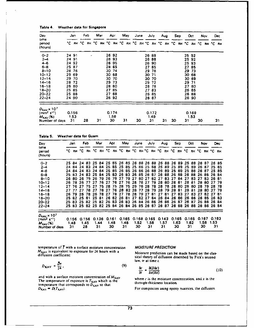
Table 4. Weather data for Singapore
Day Jan Feb Mar Apr May June July Aug Sep Oct Nov Dectimeperiod *C RH *C RH 'C RH *C RH *C RH *C RH "C RH *C RH C RH C C RH *C RH(hours)
0-2 24 91 26 92 26 88 25 922-4 24 91 26 93 26 88 25 924-6 24 92 26 95 26 90 25 936-8 25 87 28 85 27 85 27 858-10 28 76 30 74 29 76 29 73
10-12 29 69 30 68 30 71 30 6812-14 29 70 30 70 30 70 30 6914-16 28 72 29 73 29 72 29 7116-18 26 80 28 80 28 78 27 8018-20 25 85 27 85 27 83 26 8520-22 25 88 27 88 26 85 26 8822-24 24 90 26 92 26 87 26 90
DKAVx 107(mm 2 s- 1) 0.156 0.174 0.172 0.169MKAV %) 1.53 1.56 1.49 1.53Number of days 31 28 31 30 31 30 31 31 30 31 30 31
Table 5. Weather data for Guam
Day Jan Feb Mar Apr May June July Aug Sep Oct Nov Dectimeperiod "C RH *C RH "C RH *C RH *C RH 'C RH *C RH *C RH C RH NC RH OC RH OC RH(hours)
0-2 25 84 24 83 25 84 25 85 26 85 26 86 26 88 26 88 26 89 25 88 26 87 26 852-4 24 84 24 83 24 84 25 85 25 85 25 86 25 88 25 89 25 89 25 89 26 87 25 854-6 24 84 24 83 24 84 25 85 26 85 26 86 26 88 26 89 25 89 25 88 26 87 25 856-8 25 83 24 83 25 84 25 83 26 83 26 85 26 87 26 88 26 88 26 88 26 86 26 848-10 26 80 26 79 26 79 26 79 27 79 27 80 27 82 27 83 27 84 27 83 27 83 26 8110-12 26 78 26 77 27 76 27 76 27 76 28 78 27 79 28 80 28 81 28 81 28 80 27 7912-14 27 76 27 75 27 75 28 75 28 75 29 76 28 78 28 78 28 80 28 80 28 79 28 7814-16 27 77 27 76 27 76 27 76 28 82 28 77 28 79 28 79 28 81 28 81 28 80 27 7916-18 26 79 26 78 26 78 27 78 27 78 28 79 27 81 27 81 27 83 27 83 27 82 27 8118-20 25 82 25 81 25 81 26 82 26 81 27 82 27 84 26 84 26 86 26 86 26 85 26 8320-22 25 83 25 82 25 82 26 83 26 83 26 84 26 86 26 86 26 87 26 87 26 86 26 8422-24 25 83 25 82 25 82 25 84 26 84 26 85 26 87 26 87 26 88 26 88 26 86 26 84
DKAV x 107(mm 2 s- 1 ) 0.156 0.156 0.136 0.161 0.165 0.168 0.165 0.143 0.165 0.165 0.167 0.163MKAV (%) 1.48 1.45 1.44 1.48 1.48 1.52 1.58 1.57 1.63 1.62 1.58 1.53Number of days 31 28 31 30 31 30 31 31 30 31 30 31
temperature of T with a surface moisture concentration MOISTURE PREDICTIONMAv is equivalent to exposure for 24 hours with a Moisture prediction can be made based on the clas-diffusion coefficient: sical theory of diffusion described by Fick's second
law. ie at time t.
24 ' a(Di ) (10)
and with a surface moisture concentration of MKAv. where c is the moisture concentration, and x is theThe temperature of exposure is TKAv which is the through-thickness location.temperature that corresponds to DKAv so thatDKAv= D(TK.v). For composites using epoxy matrices, the diffusion
73
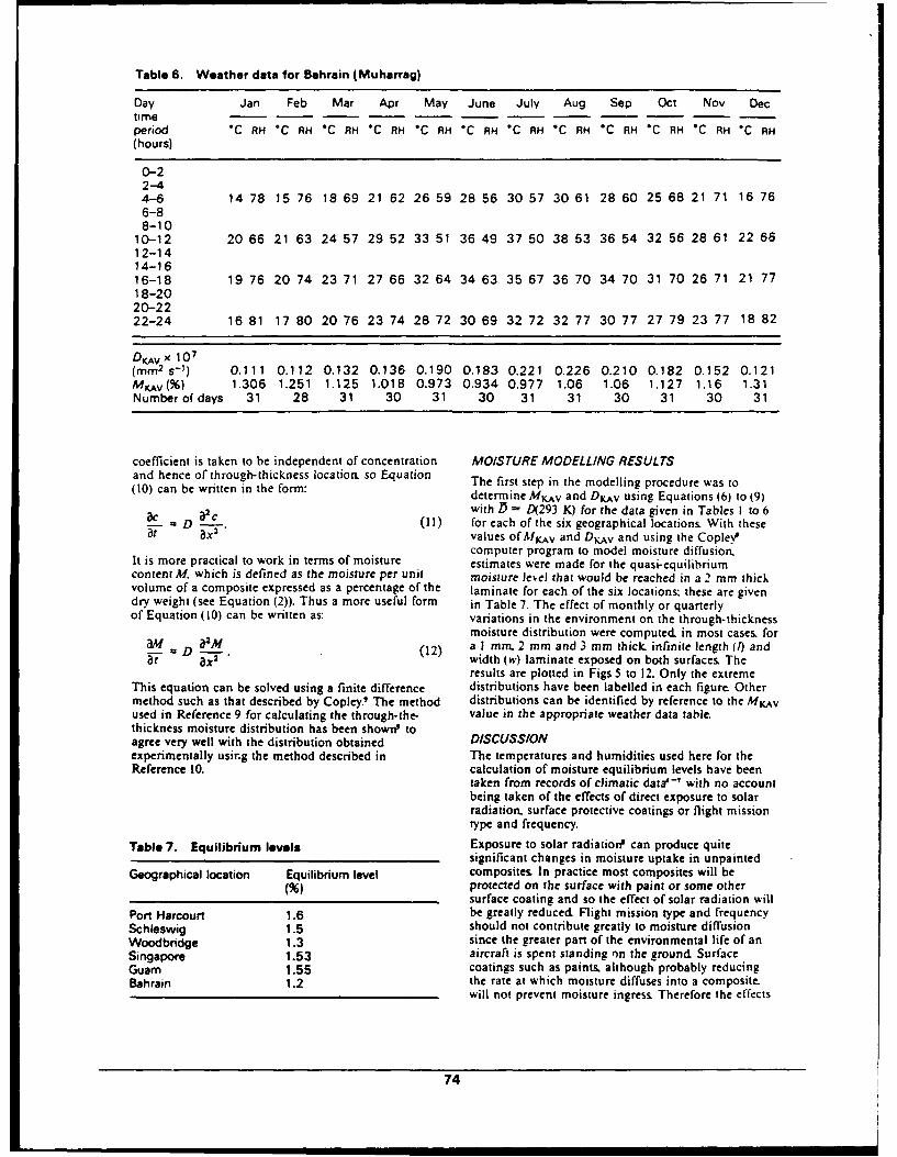
Table 6. Weather data for Bahrain (Muharrag)
Day Jan Feb Mar Apr May June July Aug Sep Oct Nov Dectimeperiod *C RH *C RH 'C RH "C RH *C RH *C RH "C RH *C RH *C RH 'C RH *C RH 'C RH(hours)
0-22-44-6 14 78 15 76 18 69 21 62 26 59 28 56 30 57 30 61 28 60 25 68 21 71 16 766-88-10
10-12 20 66 21 63 24 57 29 52 33 51 36 49 37 50 38 53 36 54 32 56 28 61 22 6612-1414-1616-18 19 76 20 74 23 71 27 66 32 64 34 63 35 67 36 70 34 70 31 70 26 71 21 7718-2020-2222-24 16 81 17 80 20 76 23 74 28 72 30 69 32 72 32 77 30 77 27 79 23 77 18 82
DKAv x 107(mm 2 s-1) 0.111 0.112 0.132 0.136 0.190 0.183 0.221 0.226 0.210 0.182 0.152 0.121MKV(%) 1.306 1.251 1.125 1.018 0.973 0.934 0.977 1.06 1.06 1.127 1.16 1.31Number of days 31 28 31 30 31 30 31 31 30 31 30 31
coefficient is taken to be independent of concentration MOISTURE MODELLING RESULTSand hence of through-thickness location, so Equation The first step in the modelling procedure was to(10) can be written in the form: determine MKv and DKAv using Equations (6) to (9)
a1 with D = D(293 K) for the data given in Tables I to 6S-a". (11) for each of the six geographical locations. With these
8t ax2 values of MKAv and DKv and using the Cople.Pcomputer program to model moisture diffusion.
It is more practical to work in terms of moisture estimates were made for the quasi-equilibriumcontent M. which is defined as the moisture per unit moisture leveJ that would be reached in a 2 mm thickvolume of a composite expressed as a percentage of the laminate for each of the six locations: these are givendry weight (see Equation (2)). Thus a more useful form in Table 7. The effect of monthly or quarterlyof Equation (10) can be written as: variations in the environment on the through-thickness
moisture distribution were computed. in most cases. foram D a-M (12) a I mm. 2 mm and 3 mm thick. infinite length (I) and
aX2 width (w) laminate exposed on both surfaces. Theresults are plotted in Figs 5 to 12. Only the extreme
This equation can be solved using a finite difference distributions have been labelled in each figure Othermethod such as that described by Copley.' The method distributions can be identified by reference to the MKAvused in Reference 9 for calculating the through-the- value in the appropriate weather data table.thickness moisture distribution has been shown' toagree very well with the distribution obtained DISCUSSIONexperimentally using the method described in The temperatures and humidities used here for theReference 10. calculation of moisture equilibrium levels have been
taken from records of climatic data'' with no accountbeing taken of the effects of direct exposure to solarradiation, surface protective coatings or flight missiontype and frequency.
Table 7. Equilibrium levels Exposure to solar radiation" can produce quitesignificant changes in moisture uptake in unpainted
Geographical location Equilibrium level composites. In practice most composites will beprotected on the surface with paint or some othersurface coating and so the effect of solar radiation will
Port Harcourt 1.6 be greatly reduced Flight mission type and frequencySchleswig 1.5 should not contribute greatly to moisture diffusionWoodbridge 1.3 since the greater part of the environmental life of anSingapore 1.53 aircraft is spent standing qn the ground SurfaceGuam 1.55 coatings such as paints, although probably reducingBahrain 1.2 the rate at which moisture diffuses into a composite.
will not prevent moisture ingress. Therefore the effects
74
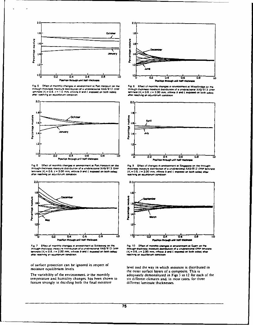
2.0 2.0
I16
L21.2
0 0.2 0.4 0.6 0.8 0010 . 0.4 0.6 0.8 LOPosition twougih unit hlf-lIcna Posto Ileu uMhl-hcns
Fig 5 Effect of monthly changes in envionmnent at Port Harcourt on the Fg. 8 Elffact of monthly changes in envionment at Woodbridge on thethrough' thickness moisture distribution of a unidirectional XAS/9 I 3 CFRP through- thickness moisture distribution of a unidirectionial XAS'91 3 cFRPlaminiate (VI a0.6. r - 1.0 rm. infinite b andlI expoise on both sides) lamilnate I Vi= 0.6. t w 2.00 min. infinite At and I. exposed on both 54d0sfafter reaching an equilibrium condition after reaching ant equilibrium condition
zC 2.0
32.4 July 1.
L2- 1.2-
-0 0 A2 0. 6 0.8 1.0 0.2 0.4 0.6 0.8 10Position through uijtf fslf-thictns Psto Nwo uni hot~iiclune
Fig 6 Effect of monthly changes in enirponment at Port H~arcourt on the Fig 9 Effect of changes in enirnment at Singapore on the through,through,'thocknass moisture distribution of a unidiectional XAS/913 CFRP thickness moisture distribution of a unidirectional XAS/913 CFP leminazalaminate V =0.6. r =3.00 mm. nfinuta bandtexpoeedoanboth side( tV - 0.6. t -2.00 m n~lfiniteb6and. expoedn both sdesatraftert reaching an equitibnium condition reaching an equilibnium condition
02 L22 0. . . 0 1 02 04 0608
Position Vroigh tut haif-thiCitrae Posto fio w*Wil
Fg 7 Effect of monthly changes in environiment et Schissawug on the Fig. 10 Effect of monthly changes in envionmenut at Guam on thethrough,- thickness moisture ditriblution ofla unidirectional XAS/9 13 CFAP through. thickness moit distribution of a unidirectional CFflP laminatelaminate (V, a 086. -2=00 mot infinite b anid I exposeed on both sidegi I V, - 0-6. t- 2.00 mm.x infinite b aft . exposed on both sides) afterafter reaching an equilibnium condition rscing an equilibrium condition
of surface protection can be ignored in respect of level and the way in which moisture is distributed inmoisture equilibrium levels the Outer surface layers of a composite. This isThe variability at the environment. ie the monthly adequately demonstrated in Figs 5 to 12 for each of thetemperature and humidity changes& has been shown to six different climates and, in most cases, for threefeature strongly in deciding both the final moisture different laminate thicknesses.
75
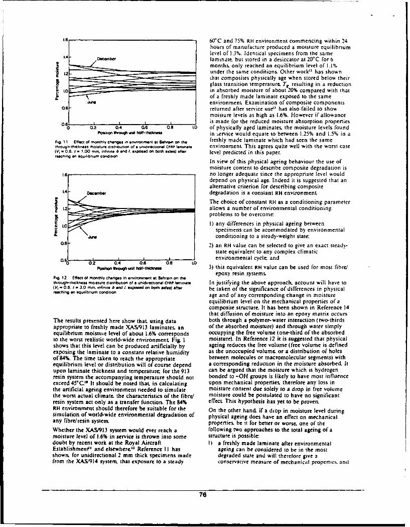
It. 60'C and 75% RH environment commencing within 24hours of manufacture produced a moisture equilibriumlevel of 1.3%. Identical specimens from the same
1.4 OaC.rber laminate but stored in a desiccator at 20°C for 6months only reached an equilibrium level of 1.1%
2 - under the same conditions. Other work" has shownthat composites physically age when stored below theirI. glass transition temperature, Tr resulting in a reduction
LO L in absorbed moisture of about 20% compared with thatof a freshly made laminate exposed to the same
renvironment Examination of composite componentso.8 returned after service use' has also failed to show
moisture levels as high as 1.6%. However if allowance0.6 iis made for the reduced moisture absorption properties
0 0.2 0.4 06 0.8 LO of physically aged laminates, the moisture levels foundPositionthrough uni hf-icliets in ervice would equate to between 1.25% and 1.5% in a
Fig. 1 1 Effect of monthly changes in eirronment at Bahrin on th freshly made laminate which had seen the samethrough-tthickness moisture distribution of a unidirectional CFRP laminate environment. This agrees quite well with the worst case(V, w 0.6. f = 1.00 mm, infinte b exposed on both ides) after level predicted in this paper.reaching an equilibrium condition
In view of this physical ageing behaviour the use ofmoisture content to describe composite degradation is
1.6 no longer adequate since the appropriate level woulddepend on physical age. Indeed it is suggested that analternative criterion for describing composite
L4 - .Oernber degradation is a constant RH environment
The choice of constant RH as a conditioning parameterL2 -allows a number of environmental conditioning
problems to be overcome:
I ) any differences in physical ageing betweenspecimens can be acommodated by environmental
conditioning to a steady-weight state.0.8 2) an RH value can be selected to give an exact stead)-
state equivalent to any complex climatic
0 | . 04 .6 0 environmental cycle: and0.2 0.4 0.6 0.8 toPosition tughwit f-thiCnss 3) this equivalent RH value can be used for most fibre/
epoxy resin systems.Fig 12 Effect of monthly changes in environment at Bahrain on tihe
through-thickness moisture distribution of a unidirectional CFRP laminate In justifying the above approach. account will have to(V, - O.6. r - 3.0 min infinite b nd/. eposed on bo sidesafter be taken of the significance of differences in physicalreaching an equilibrium condition age and of any corresponding change in moisture
equilibrium level on the mechanical properties of acomposite structure. It has been shown in Reference 14that diffusion of moisture into an epoxy matrix occurs
The results presented here show that using data both through a polymer-water interaction (two-thirdsappropriate to freshly made XAS/913 laminates, an of the absorbed moisture) and through water simplyequilibrium moistuie level of about 1.6% corresponds occupying the free volume (one-third of the absorbedto the worst realistic world-wide environment Fig, I moisture). In Reference 12 it is suggested that physicalshows that this level can be produced artificially by ageing reduces the free volume (free volume is definedexposing the laminate to a constant relative humidity as the unoccupied volume. or a distribution of holesof 84%. The time taken to reach the appropriate between molecules or macromolecular segments) withequilibrium level or distribution will of course depend a corresponding reduction in the moisture absorbed. Itupon laminate thickness and temperature for the 913 can be argued that the moisture which is hydrogenresin system the accompanying temperature should not bonded to -OH groups is likely to have most influenceexceed 45°C.' It should be noted that in calculating upon mechanical properties, therefore any loss inthe artificial ageing environment needed to simulate moisture content due solely to a drop in free volumethe worst actual climate. the characteristics of the fibre/ moisture could be postulated to have no significantresin system act only as a transfer function. The 84% effect This hypothesis has yet to be proven.RH environment should therefore be suitable for the On the other hand if a diop in moisture level duringsimulation of world-wide environmental degradation of physical ageing does have an effect on mechanicalany fibre/resin system properties. be it for better or worse. one of the
Whether the XAS/913 system would ever reach a following two approaches to the total ageing of amoisture level of 1.6% in service is thrown into some structure is possible:doubt by recent work at the Royal Aircraft I) a freshly made laminate after environmentalEstablishment" and elsewhere." Reference I I has ageing can be considered to be in the mostshown. for unidirectional 2 mm thick specimens made degraded state and will therefore give afrom the XAS!914 system that exposure to a steady conservative measure of mechanical properties, and
76
2) the physical ageing process can be accelerated by REFERENCESannealing at a temperature below T, for a specified I Augl, J.N. 'The effect of moisture on carbon fibre reinforcedtime." thus establishing a standard condition epoxy composites - Pan I: Mechanical property changes'before environmental ageing NSWC/WOITR76-149 (1977)
2 Ceiliali T.A. and Copley. S6.N RAE Technical Report (to beClearly some understanding of the effects of physica" pubiished)ageing on British resin systems, and work to promote 3 Sbe.. Cr- and Sprimger, G.& Moisture absorption andthis understanding. is needed. desorption of composite materials J Composite Maier 10
(January 1976) pp 2-204 'Amt fur Wehrgeophysik" W75 AZ 31-50-22 (April 1982)5 Terhnical Report AC-793 (Gruman Aerospace Corporatio.
November 1979)6 Pviroie communication (Metereological Office. BracknelL
CONCLUSIONS Berkshire. UK)7 *Environmental handbook for guided weapons: MOD'PE
I) Using a prescribed moisture level to define ArP35degradation appropriate to given service 8 Augl. J.M. anod Berer A.L *The effect of moisture onexperience is not valid, carbon fibre reinforced composites. Part Ill: Prediction of
moisture sorption in real outdoor environmernt NSWC/2) A suggested better alternative is to prescribe a WOL/TR-77-IJ (September 1976)
fixed RH value for long enough to ensure any 9 Copley. SM. A computer program to model moisturediffusion and its application to accelerated ageing of
given matrix system reaches an equilibrium composites' RAE Technical Report 82010 (Royal Aircraftcondition in thin structures or a representative EstablishmenL UK. 1982)through-thickness moisture distribution for thick I0 Collings, T.A. and Copley. S.M. 'On the accelerated ageing ofstructures CFRP Composites 14 No 3 (July 1984) pp 180-188
II Mead. 1L Pn'sate communication (Royal Aircraft3) Work needs to be done to compare the moisture Establishment. UK)
equilibrium levels and the mechanical properties 12 Kon, ESW. ad Adamso.. M. "Physical ageing and itsof freshly made and physically aged laminates effect on the moisture sorption of amine-cured epoxies'after they have been conditioned to a fixed RH Polymer Communications 24 (June 1983)environment 13 Hedrick. LG. and Whiteide, J., 'Effects of environment on
advanced composite structures AIAA Conf on AircraftComposites San Diega CA USA 24-25 March 1977
14 Adasama, MLJ.JMaierSci 15 (1980)
ACKNOWLEDGEMENT AUTHOR
Dr Collings is with the Materials and StructuresDepartment. X32 Building. Royal Aircraft
V Copyright Controller. HMSO. London 1984. Establishment Farnborough. Hants. GU14 6TD. UK
77