Embed Size (px)
Citation preview

OFFICIAL
OFFICIAL
ONR379 - Review of RGP, Statute and Regulations Applicable to the Performance, Integrity and Execution of Bolted Connections for Primary Containment and Transport Packages
Date January 2020 Author(s) Client Reference F.A.1.11.4.3322 - ONR379 Wood Reference 208736-AA-0002 Version Number 2.0


OFFICIAL
208736-AA-0002 Version 2.0
Page 3 of 443
OFFICIAL
Executive Summary
There have been a number of incidents reported to the ONR of loosened bolts in the closures of Transport Packages in the last decade. These incidents were reported when bolts had loosened to such an extent that bolts either had disassembled completely during transport, or could be disassembled by hand and hence easily detected. It is reasonable to assume that the number that had loosened to some lesser extent, and therefore deviating from the assured design sealing conditions for nuclear containment, must be far greater. The design of appropriate and reliable mechanical fasteners and joints is complex and stakeholders are warned against being facile in their treatment, due to fasteners familiarity, and particularly when dependent on their performance for Nuclear Safety. A fully tightened bolted joint can sustain millions of load cycles without problems, a joint consisting of untightened bolts will frequently disassemble or fail within a few cycles and may have catastrophic consequences. The review was conducted in a top-down hierarchical manner in approximate order of precedence, starting with relevant IAEA Safety Standards and UK Statute which forms the basis of the objectives of guidance and good practice. IAEA Safety Standards and UK Statute have precedence and define high level and fundamental safety requirements. In addition, for Transport Activities, specific legislation requires the achievement of detailed performance criteria to ensure a common level of safety and facilitate trans-frontier transport of radioactive material. However, when used on a Licensed Site such packages are also subject to the same legal UK statutory requirements as other site facilities and activities. Potentially applicable Relevant Good Practice (RGP) is also tiered in priority as explained in ONR SAP ECS.3:
(i) Nuclear specific UK (Euronorms also being considered as UK) standards; and if no appropriate standards exists
(ii) International standards (iii) Industry standards if required
Transport packages, and other nuclear structures are constructed from a wide variety of materials, including structural steels, stainless steels, aluminium alloys and wood. Use of materials other than structural steel is increasingly common. Austenitic stainless steels offer superior environmental corrosion properties, and duplex stainless steels have greater strength and impact resistance. It is estimated that approximately 85% of recent Design Approval Applications or Renewals have containment boundaries or barriers fabricated from stainless steel materials. Transport packages may have a number of barriers and closures. Generally, there is an inner receptacle constructed from stainless steel and sealed with a bolted closure (possibly using stainless steel bolts). Closures in Transport packaging typically consist of bolted interfaces in containment boundaries. Bolting assembly materials typically used include Carbon Steel (Grade 8.8, 10.9 & 12.9), Alloy Steel to ASTM A320 Alloy Steel (L7) or Stainless steel (Grade A2 or A4) and are selected for electrolytic compatibility with the fabrication material. Selected bolting assemblies may be commercial off-the-shelf or designed and manufactured by the Constructor. Bolts are typically torque tightened to a level claimed to be sufficient to produce the tension, sealing and security of nuclear containment on which the Package Design Approval was based. Typical design standards reflect Transport Container Safety Committee Guidance, particularly TCSC 10061, which is a guide specifically for lifting, tie-down and retention systems of Transport Packages.
1 TCSC 1006 Transport of Radioactive Material Code of Practice - Guide to the Securing/Retention of Radioactive Material Payloads and Packages During Transport. July 2018

OFFICIAL
208736-AA-0002 Version 2.0
Page 4 of 443
OFFICIAL
However, in the absence of any other specific guidance, practice for all structural elements of Packages typically follow the same standards. The typically used codes and standards are BS 2573 Part 1 for structural strength, BS EN 1993-1-9 or BS 7608 for fatigue, and BPVC for containment under elevated temperature and pressure. The European Machinery Directive (BS 130012) is recommended for use by TCSC 1006, when all parts are published, but is not typically used. These standards are explicitly intended for structural steel structures, and do not contain tailored guidance for the other materials such as stainless steels which deviate in surface properties, behaviours and failure modes. There are, in fact, no parts of BS EN 13001 remaining unpublished that should prevent the use of BS EN 13001 for Transport Package lifting elements. The need for adoption of consistent codes and standards should take precedence and BS EN 13001 and its sub-divisions should be used for elements of Transport Packages performing a lifting function. It is consistent with the other Eurocode standards. It is essential that bolts be preloaded to 70% of ultimate breaking strength in order to prevent loosening during fluctuating loading (e.g. transport vibration). Tightness in UK bolting systems can be assured by tensioning to an extent that induces ductility in the shank of the bolt, and it is therefore desirable for the male thread to have slightly overmatched properties in comparison to the female thread. This is not necessarily possible were either the bolt or threaded female nut or hole is comprised of stainless steel. Stainless steels exhibit fundamentally different behaviour under load to structural steels. Stainless steels stress-strain behaviour deviates from linearity at loads much lower than the 0.2% proof strain, which for structural steels can be taken as being equivalent to material yield stress. For carbon, alloy and structural steel it is a reasonable approximation to consider elastic behaviour to exist to the quoted 0.2% proof strain. Stainless steels exhibit plasticity at much lower loads and the deviation to linear behaviour is not controlled by the material standard. Therefore, whilst stress limits, relative to ultimate breaking loads, prescribed in steelwork codes, may provide a suitable margin of safety against failure for stainless steels, they are not suitable in all circumstances, particularly where strain and deflection are important to good performance. This effect is particularly important for stainless steel closure bolts, threaded nuts or tapped holes as gapping cannot be reliably predicted under load without consideration of non-linear behaviour. Furthermore, stainless steels of similar compositions have a tendency to adhere in contact, and therefore the thread friction coefficients can be highly variable and uncertain. At higher contact loads galling between similar stainless steels is a common issue and fasteners cannot be reliably pre-tensioned to a specific level. Galling may also result in unacceptable wear. The standard rules3 for carbon steel bolt tension and tightening do not apply to other bolting materials and are not valid for stainless steel construction without additional characterisation measures4. The current typically used design codes, in addition to being un-maintained, superseded or outdated, are not intended for the design and execution of structures constructed from a typical range of arbitrary materials, and are focussed on structural steels. The Eurocode suite is intended to provide tailored guidance for a variety of material types commonly used in engineering construction.
The Eurocodes are seen as leading the way in structural codes5. Their flexibility enables adoption and use not only within Europe, but internationally. This feature has been recognized by several countries outside Europe and they are already committed to adopting Eurocodes. 2 BSI Standards Publication. Cranes - General Design. Part 3-1: Limit States and proof competence of steel structure. BS EN 13001-3-1:2012+A1:2013 3 BRITISH STANDARD Guide to design considerations on The strength of screw threads BS 3580:1964 4BSI Standards Publication. Execution of steel structures and aluminium structures Part 2: Technical requirements for steel structures. BS EN 1090‑2:2018 5BSI Website: https://shop.bsigroup.com/Browse-By-Subject/Eurocodes/

OFFICIAL
208736-AA-0002 Version 2.0
Page 5 of 443
OFFICIAL
The primary objectives of the Eurocodes are to:
Provide common design criteria and methods of meeting necessary requirements for mechanical resistance, stability and resistance to fire, including aspects of durability and economy
Provide a common understanding regarding the design of structures between owners, operators and users, designers, contractors and manufacturers of construction products
Facilitate the marketing and use of structural components and kits in EU Members States
Facilitate the marketing and use of materials and constituent products, the properties of which enter into design calculations
Be a common basis for research and development, in the construction industry
Allow the preparation of common design aids and software
Increase the competitiveness of the European civil engineering firms, contractors, designers and product manufacturers in their global activities.
The objectives of the Eurocode suite match very closely with those for nuclear safety, and regulatory requirements for structural integrity, serviceability, impact, human error, hazard avoidance, reliability management, execution, inspection and durability. The Eurocode suite forms a complete and comprehensive guide to the design of structures, containing detailed advice appropriate to type of structure, construction materials, construction method, load action and environment. BS EN 19906 is the highest level guide for the Basis of Structural Design and refers down to Specific Eurocodes for load actions, design of concrete, steel, aluminium, timber and masonry structures (etc.). The Specific Eurocodes typically branch into further parts for fire design and the design of beam, shell and plated structures and the design of joints (etc.). The Eurocodes are designed to be used as a suite of complimentary documents governing the use of specific materials or construction types, but when used holistically may assure the structural integrity of complete structures, which may have diverse features and construction materials while being subject to diverse load actions, to a consistent margin of safety. The design of bolted joints should always, as a minimum, be in accordance with BS EN 1993-1-87 (Design of Steel Structures: Design of joints). Complementing the structural design codes is BS EN 1090-1/2/3. BS EN 1090-28 contains detailed guidance for the delivery of high quality structural bolted connections that can be assured to meet design requirements. Good bolting performance should be assured by the application of a combination of Good Practices, specified in BS EN 1090, including:
the requirements of a Quality Plan;
the grading of Execution Class according to consequences;
the suitability for preloading of bolting assemblies;
the design of bolting assemblies, appropriate grades, including Direct Load Indicators and Shear Nuts;
the specification of bolting assemblies with controlled surface properties (to BS EN 14399) and friction coefficients, or the testing of “special” bolts to determine the coefficients relating torque to tension;
the methods of tightening and assembly to assure good tensioning and continued “tightness”;
the methods of inspection and graded sampling approach; and
6British Standard. Eurocode — Basis of structural design. BS EN 1990:2002 +A1:2005 Incorporating corrigenda December 2008 and April 2010 7British Standard. Eurocode 3: Design of steel structures — Part 1-8: Design of joints. BS EN 1993-1-8:2005 Incorporating Corrigenda December 2005, September 2006, July 2009 and August 2010 8 BSI Standards Publication. Execution of steel structures and aluminium structures Part 2: Technical requirements for steel structures. BS EN 1090‑2:2018

OFFICIAL
208736-AA-0002 Version 2.0
Page 6 of 443
OFFICIAL
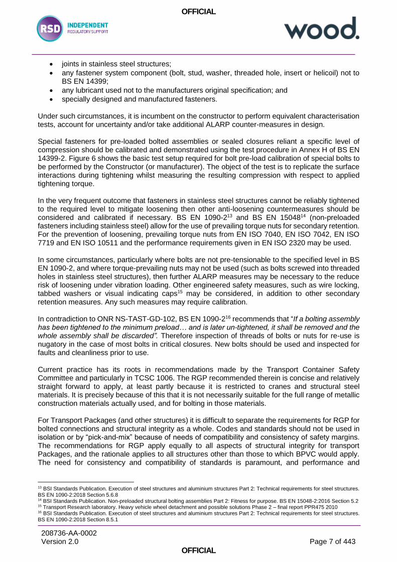
anti-galling measures. Figure 1 is a highly simplified high level overview of the tree of Eurocodes, with specific consideration of common construction materials comprising Transport Packages. The standards are branched into detailed requirements, depending on the consequences of material choices and load actions. When BS EN 1090 is applied to a bolted joint comprised of structural steels then bolting assemblies (nuts, bolts and washers) compliant to BS EN 14399 (e.g. Grade 8.8/10.9) can be purchased. Such fasteners are supplied with manufacturer assured friction coefficients, determined using tests performed by the manufacturer in accordance with BS EN 14399-29. The k-class and k-factor (and k-variance) allow calculation of appropriate applied torque values to produce the design bolt tension and joint compression, and in conjunction with the other quality processes in BS EN 1090-2 then good behaviour can be assured to a level commensurate with Regulatory Expectations. As previously stated the most common material of construction used for the fabrication of Transport Packages is stainless steel (frequently 304L), and this is understandably preferred for corrosion resistance. By necessity of the containment function Transport packages consist of receptacles and outer packaging, which are usually sealed by bolted closures. Sealing requires packages to resist internal and external pressures, and therefore sealing and closure tightness must be assured by bolt tensioning to the design value defined in the justification. Transport (Routine and Normal) loading is multi-axial and fluctuating and therefore imposes separating tensile loading on closures. Impact loading (Accidental Conditions) may impose violent loads separating the closures. The choice of stainless steel as a construction material, or other special fasteners, has somewhat insidious consequences on the ability to assure the good performance of bolted joints, as shown in Figure 1. Stainless steel bolting elements (either stainless steel fabrications, bolts, nuts or threaded holes) are generally:
not considered suitable for tensile loading10, which is essential to resist Transport Loads; and
not recommended for pre-loading (to 70% of ultimate breaking load11), which is essential for:
o containment; and
o prevention of loosening12 SSR-6 paragraph 503 requires that all closures should be checked, prior to shipment, to be sealed in the manner assumed in the design approval and paragraph 613 requires that bolting assemblies shall be designed to prevent loosening. However, such assurances cannot be guaranteed because of limitations of the typically used stainless steel materials and currently applied codes and standards. The designer and Applicant faces a quandary of mutually exclusive requirements, and some compromise is inevitable if stainless steel is a necessity for corrosion resistance. The decision making process in making design choices, as well as any further ALARP measures to minimise residual risk, should form a clear part of any justification and be available to regulators. It is essential that the applicant recognises when then design has departed from the scope of the convenient execution rules applicable to standard bolted assemblies in structural steel structures, and when fasteners should be considered as “special”. Examples of special fasteners are:
9 BSI Standards Publication. High-strength structural bolting assemblies for preloading Part 2: Suitability for preloading BS EN 14399-2:2015 10 BSI Standards Publication. Execution of steel structures and aluminium structures Part 2: Technical requirements for steel structures. BS EN 1090‑2:2018, Section 5.6.4 11 BRITISH STANDARD. Eurocode 3: Design of steel structures — Part 1-8: Design of joints. BS EN 1993-1-8:2005 Section 3.6.1 12 BSI Standards Publication. Execution of steel structures and aluminium structures Part 2: Technical requirements for steel structures. BS EN 1090‑2:2018, Section 8.2.1
OFFICIAL
208736-AA-0002 Version 2.0
Page 7 of 443
OFFICIAL
joints in stainless steel structures;
any fastener system component (bolt, stud, washer, threaded hole, insert or helicoil) not to BS EN 14399;
any lubricant used not to the manufacturers original specification; and
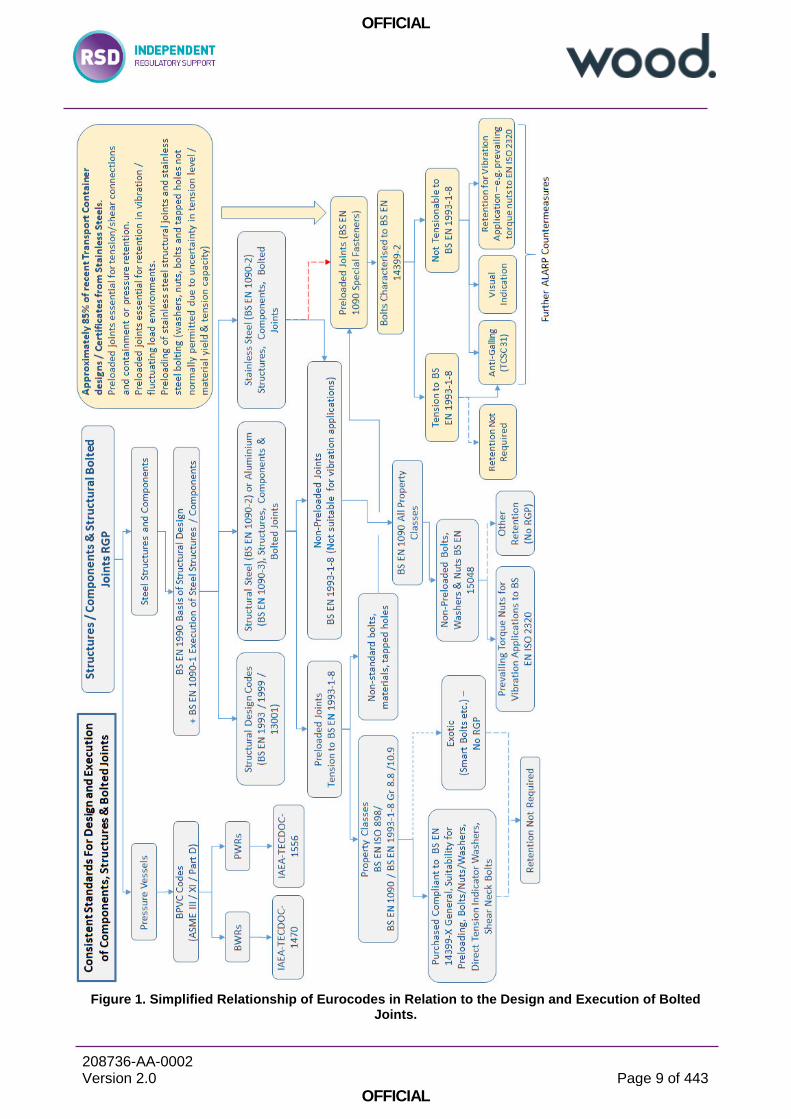
specially designed and manufactured fasteners. Under such circumstances, it is incumbent on the constructor to perform equivalent characterisation tests, account for uncertainty and/or take additional ALARP counter-measures in design. Special fasteners for pre-loaded bolted assemblies or sealed closures reliant a specific level of compression should be calibrated and demonstrated using the test procedure in Annex H of BS EN 14399-2. Figure 6 shows the basic test setup required for bolt pre-load calibration of special bolts to be performed by the Constructor (or manufacturer). The object of the test is to replicate the surface interactions during tightening whilst measuring the resulting compression with respect to applied tightening torque. In the very frequent outcome that fasteners in stainless steel structures cannot be reliably tightened to the required level to mitigate loosening then other anti-loosening countermeasures should be considered and calibrated if necessary. BS EN 1090-213 and BS EN 1504814 (non-preloaded fasteners including stainless steel) allow for the use of prevailing torque nuts for secondary retention. For the prevention of loosening, prevailing torque nuts from EN ISO 7040, EN ISO 7042, EN ISO 7719 and EN ISO 10511 and the performance requirements given in EN ISO 2320 may be used. In some circumstances, particularly where bolts are not pre-tensionable to the specified level in BS EN 1090-2, and where torque-prevailing nuts may not be used (such as bolts screwed into threaded holes in stainless steel structures), then further ALARP measures may be necessary to the reduce risk of loosening under vibration loading. Other engineered safety measures, such as wire locking, tabbed washers or visual indicating caps15 may be considered, in addition to other secondary retention measures. Any such measures may require calibration. In contradiction to ONR NS-TAST-GD-102, BS EN 1090-216 recommends that “If a bolting assembly has been tightened to the minimum preload… and is later un-tightened, it shall be removed and the whole assembly shall be discarded”. Therefore inspection of threads of bolts or nuts for re-use is nugatory in the case of most bolts in critical closures. New bolts should be used and inspected for faults and cleanliness prior to use. Current practice has its roots in recommendations made by the Transport Container Safety Committee and particularly in TCSC 1006. The RGP recommended therein is concise and relatively straight forward to apply, at least partly because it is restricted to cranes and structural steel materials. It is precisely because of this that it is not necessarily suitable for the full range of metallic construction materials actually used, and for bolting in those materials. For Transport Packages (and other structures) it is difficult to separate the requirements for RGP for bolted connections and structural integrity as a whole. Codes and standards should not be used in isolation or by “pick-and-mix” because of needs of compatibility and consistency of safety margins. The recommendations for RGP apply equally to all aspects of structural integrity for transport Packages, and the rationale applies to all structures other than those to which BPVC would apply. The need for consistency and compatibility of standards is paramount, and performance and
13 BSI Standards Publication. Execution of steel structures and aluminium structures Part 2: Technical requirements for steel structures. BS EN 1090‑2:2018 Section 5.6.8 14 BSI Standards Publication. Non-preloaded structural bolting assemblies Part 2: Fitness for purpose. BS EN 15048-2:2016 Section 5.2 15 Transport Research laboratory. Heavy vehicle wheel detachment and possible solutions Phase 2 – final report PPR475 2010 16 BSI Standards Publication. Execution of steel structures and aluminium structures Part 2: Technical requirements for steel structures. BS EN 1090‑2:2018 Section 8.5.1

OFFICIAL
208736-AA-0002 Version 2.0
Page 8 of 443
OFFICIAL
suitability of bolted joints depends on the structure and its construction materials. Good practice and regulatory compliance therefore depends on the full adoption of the Eurocode suite. It is concluded that typical current practice is unsuitable for application to the range of construction and bolting materials in actual use for typical Transport Packages. The use of stainless steels has some mutually exclusive requirements with the codes and standards currently typically used, particularly in the ability to ensure bolt tension meets levels assumed in the justification of compliance to containment requirements in Accidental Conditions of Transport, and to meet such a level that loosening can be assured not to occur during Normal and Routine Conditions. When Codes and Standards are reviewed holistically it is impossible to come to any other conclusion other than the full adoption of the Eurocodes suite is necessary to satisfy IAEA Safety Standards, UK Regulations and ONR SAPs – the pre-EN British standards are typically superseded, not maintained or do not form an integrated suite of current Good Practice suitable for all materials. Eurocodes (BS EN 1990 and downward) address the typical issues for the materials in actual use, have safety objectives very closely aligned with those necessary for nuclear applications, and identify circumstances where further ALARP measures may be necessary in order to satisfy UK statutory Requirements for on-site Activities. It is inevitable that change is likely to be resisted by Applicants’ or Licensees’ due to human nature and the experience of designers involved in the process. However, change in engineering Good Practice and accounting for its consequences should be considered normal practice during Periodic Safety Review and renewal applications for Transport Packages. Due to the combinations of stress and load factors (by comparison of BS 2573 Part 1 and typical EN codes) adoption of Eurocodes is unlikely to have safety implications for structures. However, for bolting arrangements and particularly structures comprised of materials other than structural steels, review against current RGP is necessary to determine risk to be ALARP for site Activities and Facilities, and may result in real safety improvements for fastener systems. A key element of the identified RGP may be the advice to replace any bolt on disassembly, which is to be torqued to a specific tension on re-assembly. This is necessary because it is a requirement of tightening to induce plasticity in the bolt shank, and changes in tribology may invalidate any friction assumptions used to determine applied tightening torque.
OFFICIAL
208736-AA-0002 Version 2.0
Page 9 of 443
OFFICIAL
Figure 1. Simplified Relationship of Eurocodes in Relation to the Design and Execution of Bolted Joints.
OFFICIAL
208736-AA-0002 Version 2.0
Page 10 of 443
OFFICIAL
Figure 2. Basic Test Setup for Bolt Load Calibration (Ref. F18)
OFFICIAL
208736-AA-0002 Version 2.0
Page 11 of 443
OFFICIAL
Contents
Executive Summary ........................................................................................................................ 3
1 Introduction ........................................................................................................................ 13
1.1 Background ......................................................................................................................... 13
1.2 Purpose ............................................................................................................................... 15
1.3 Scope .................................................................................................................................. 15
1.4 Document Structure ............................................................................................................. 16
2 Methodology ....................................................................................................................... 17
3 Recommendations for RGP to be Applied to Structural Bolted Joints Important to Safety .. 18
3.1 Review of IAEA Safety Standards, Regulation and Statute .................................................. 18
3.1.1 Structure of IAEA Safety Standards .............................................................................. 18
3.1.2 Review of Safety Standards .......................................................................................... 20
3.1.3 UK Statutory Requirements........................................................................................... 24
3.2 Overview of Typical Current Practice ................................................................................... 26
3.2.1 Nuclear Power Plant Boiler Pressure Vessels ............................................................... 26
3.2.2 Transport packages (and Other Structures) .................................................................. 26
3.3 Recommendations for RGP Applicable to Bolted Joints ....................................................... 30
3.3.1 Considerations in Identification of Most Appropriate RGP ............................................. 30
3.3.2 Recommendations for RGP Applicable to Bolted Joints Important to Safety for RPV Applications .............................................................................................................................. 32
3.3.3 Recommendations for RGP Applicable to Bolted Joints Important to Safety for Transport and Other Applications ............................................................................................................. 32
4 Conclusions ........................................................................................................................ 49
5 Regulatory and Technical Review of Requirements for Structural Bolted Connections ....... 51
5.1 Applicable Requirements and Clauses in IAEA Safety Standards & Regulatory Guidance .. 51
5.1.1 Extraction of Key Regulatory Requirements Applicable to All SSCs (including Structural Bolted Connections) ................................................................................................................. 51
5.1.2 Extraction of Key Regulatory Requirements Applicable to Nuclear Pressure Retention SSCs (including Structural Bolted Connections) ....................................................................... 54
5.1.3 Extraction of Key Regulatory Requirements Applicable to Transport Packages (including Structural Bolted Connections) ................................................................................................. 56
5.2 Applicable Requirements for Structural Bolted Connections in UK Statute ........................... 58
5.3 Applicable Requirements for Structural Bolted Connections in ONR Guidance .................... 61
5.3.1 ONR Guidance Applicable to All SSCs Important to Safety ........................................... 61
5.3.2 ONR Guidance Applicable to Nuclear Pressure Retaining SSCs Important to Safety.... 66
5.3.3 ONR Guidance Applicable to Transport Packages ........................................................ 66
5.4 Applicable IAEA Relevant Good Practice for Structural Bolted Connection in Nuclear Plant 68
5.4.1 IAEA RGP for Pressurised Water Reactors ................................................................... 68
5.4.2 IAEA RGP for Boiling Water Reactors ........................................................................... 69
OFFICIAL
208736-AA-0002 Version 2.0
Page 12 of 443
OFFICIAL
5.5 Current Guidance in the Assessment and Management of Transport Packages (UK) .......... 69
5.5.1 TCSC 1006 Transport of Radioactive Material Code of Practice - Guide to the Securing/Retention of Radioactive Material Payloads and Packages During Transport. July 2018 69
5.5.2 TCSC 1086 Transport of Radioactive Material Code of Practice - Good Practice Guide to Drop Testing of Type B Transport Package .............................................................................. 70
5.5.3 TCSC 1087 Transport of Radioactive Material Code of Practice - The Application of Finite Element Analysis to Demonstrate Impact Performance of Transport Package Design March 2018 70
5.5.4 TCSC 31 Transport of Radioactive Material Code of Practice - Design and Operation to Minimise Seizure of Fasteners. June 2014 ............................................................................... 70
5.6 Summary of Relevant UK and International Nuclear Applicable Relevant Good Practice for the design and execution of bolted connections ............................................................................... 72
5.6.1 Boiler Pressure Code Applicable to RPVs and other pressure retaining Nuclear Plant .. 72
5.6.2 Structural Design Codes Applicable to Transport Packages (and other Nuclear Structures Important to Safety) .................................................................................................................. 75
6 Appendices ........................................................................................................................ 90
6.1 Reviews of Relevant IAEA Safety Standards ....................................................................... 90
6.2 Reviews of Relevant UK Statute ........................................................................................ 123
6.3 Reviews of Relevant IAEA Guidance ................................................................................. 137
6.4 Reviews of Relevant ONR Guidance ................................................................................. 150
6.5 Reviews of IAEA RGP ....................................................................................................... 194
6.6 Reviews of UK Code and Standards Requirements ........................................................... 230
6.6.1 Standards Applicable to Boiler Pressure Vessels ........................................................ 230
6.6.2 Standards Applicable to Steelwork / General Fabrication ............................................ 266
6.7 Reviews of Relevant UK and International Nuclear RGP ................................................... 419
7 References ....................................................................................................................... 440
7.1 General References ........................................................................................................... 440
7.2 IAEA Safety Standards and Regulations ............................................................................ 440
7.3 UK Statute ......................................................................................................................... 440
7.4 IAEA Guidance .................................................................................................................. 440
7.5 ONR Guidance .................................................................................................................. 441
7.6 IAEA RGP .......................................................................................................................... 441
7.7 Relevant UK Codes and Standards ................................................................................... 441
7.7.1 Standards Applicable to Boiler Pressure Vessels ........................................................ 441
7.7.2 Standards Applicable to Steelwork / General Fabrication ............................................ 442
7.8 Relevant UK and International Nuclear RGP ..................................................................... 443
7.9 Relevant General RGP and Smart Bolt Technologies ........................................................ 443


OFFICIAL
208736-AA-0002 Version 2.0
Page 14 of 443
OFFICIAL
04/12/2012 Hartlepool Any problem or defect in the design, fabrication, construction, commissioning or operation of the installation that results in, or could result in, a condition that had not previously been analysed or that could significantly challenge design basis assumptions or the safety case for operation.
Fuel box found to have number of loose bolts.
08/08/2013 Dungeness B Where class 7 goods have not been transported in full compliance with any appropriate specification or regulation, except as otherwise covered by TS05.
Loose bolts found on empty fuel element bottle stillage that had been transported.
26/06/2014 Amersham An occurrence during loading, carriage or unloading of class 7 goods where there is reason to believe that there has been a significant degradation in any package safety function (containment, shielding, thermal protection or criticality) that may have rendered the package unsuitable for continued carriage without additional safety measures.
Container lid had not been bolted securely prior to transporting.
01/09/2014 Sellafield Where class 7 goods have not been transported in full compliance with any appropriate specification or regulation, except as otherwise covered by TS05.
Leak test point screw for radioactive material transport package made of wrong material.
09/09/2014 Chapelcross Where class 7 goods have not been transported in full compliance with any appropriate specification or regulation, except as otherwise covered by TS05.
Leak test point screw for radioactive material transport package made of wrong material and used in package consignments.
10/02/2015 Sizewell B Significant inadequacy in or significant failure to comply with the arrangements made under a condition attached to the Nuclear Site Licence or permission granted under a Licence Instrument.
Incorrect nuts identified as having been fitted to valve.
18/02/2015 Sellafield Any examination, inspection, maintenance, test, surveillance, alarm, alert, indication or notice that a system, structure or component reveals any matter indicating that the safe condition, including degradation of design safety barriers providing defence in depth or safe operation of that plant may be affected.
Receipt inspection identified flask to have 6 out of 16 lid bolts loose.
In respect of the use of bolted connections in SSCs important to nuclear safety it was considered important to review current Office for Nuclear Regulation (ONR) guidance against established codes and knowledge, and against other high hazard industries RGP, to identify where lessons could be learned and applied to the nuclear industry. The basis of this was to review current ONR guidance in the form of a specific number of Safety Assessment Principles (SAPs) against established cross-industry codes, regulations, codes of practice and best practice. The scope of regulation is to ensure the health, safety and welfare of workers and public (and environmental safety) are maintained. Good Practice must be measured in terms of its relevance to the activities, hazard and/or risk to which it is being applied. There may well be other good practice for many other purposes, however this report is intended to highlight good practice to meet the needs of International Safety Standards and UK Statutory Requirements. Mechanical fasteners, particularly bolts, nuts and washers are perhaps the most widely used engineering system in the world. The design of appropriate and reliable mechanical fasteners and joints is complex and stakeholders are warned against being facile in their treatment, due to fasteners familiarity, and particularly when dependent on their performance for Nuclear Safety. A
OFFICIAL
208736-AA-0002 Version 2.0
Page 15 of 443
OFFICIAL
fully tightened bolted joint can sustain millions of load cycles without problems, a joint consisting of untightened bolts will frequently fail within a few cycles and may have catastrophic consequences. Application of Good Practice for bolted joints for nuclear applications, which are important to safety, should not be seen as “gold plated” in any way. Structural design codes are typically appropriate for steelwork, cranes or steel-framed buildings, which are undoubtedly safety critical to those using them. However, additional potentially broader risks exist as a consequence of failures in Nuclear Safety. There are clear UK Statutory requirements to implement RGP, and grading within the design codes accounts for the stringency in application to the arguably lower consequence civil structures for which the design codes were primarily intended in terms of societal risk. Across any nuclear installation, there are numerous instances of bolted designs that directly impact nuclear safety including mechanical plant, containment systems and structures. With respect to transport of radioactive materials (RAM), there are four key aspects of safety19 that are governed by the regulatory framework, one of which is containment of the radioactive contents. Packages often use bolted designs to provide this primary containment function. Confidence in the bolting arrangements is therefore essential to assure nuclear safety and safety during transport of radioactive materials. The performance of bolted systems for containment of radioactive material, for example in transport packages, is heavily dependent on the applied pre-load torque. While this torque can be calculated accurately when the overall length of the tightened bolt can be measured, many designs preclude this measurement being taken, and consequently reliance is placed on other processes, which are subject to inherent uncertainty.20
1.2 Purpose
This research project supports ONR’s strategic theme of ‘Influencing improvements in nuclear safety and security’ by providing greater understanding of primary containment systems during transport, enabling more effective designs to be developed, which provide greater confidence in their performance. This project supports ONR’s objective in the Research Strategy ‘to test claims made in licensees’ safety cases where there is recognition there may be significant uncertainties’ by reducing the uncertainty associated with this aspect of the design. The regulatory expectations against adequacy of bolted designs can be on occasion judgement led by individuals with limited internal guidance. There is also limited relevant good practice in the nuclear industry to underpin assessment processes for bolting designs that allow for the uncertainties inherent through tolerances, lubrication, pre-torque application or tightening sequencing. This project will reduce uncertainties and enable more structured challenge to duty holder safety cases in establishing adequate bolted designs and substantiation with particular reference back to design codes and standards.
1.3 Scope
The scope of this project is to establish for UK nuclear facilities and duty-holders engaged in the transport of radioactive materials, through investigation, analysis and review, relevant good practices for bolting designs and operation for bolted systems important to safety, leading to the production of
19 See Reference A8, SSR-6 2012 Para 104 “The objective of these Regulations is to establish requirements that must be satisfied to ensure safety and to protect persons, property and the environment from the effects of radiation in the transport of radioactive material. This protection is achieved by requiring:
(a) Containment of the radioactive contents; (b) Control of external radiation levels; (c) Prevention of criticality; (d) Prevention of damage caused by heat.”
20 ONR/T3350 Technical Support – Work Order Specification
OFFICIAL
208736-AA-0002 Version 2.0
Page 16 of 443
OFFICIAL
guidance to industry and/ or inspectors. The research may include testing and analysis of bolts to provide specific evidence to inform design decisions.
1.4 Document Structure
This document is structured as follows:
Section 1: Introduction, including purpose and scope of this assessment
Section 2: The overall methodology of this assessment The rationale and precedence used in identification of RGP.
Section 3: Recommendations for RGP to be Applied to Structural Bolted Joints Important to Safety This is the recommendation for good practices that may be applied to bolted joints which may have an important contribution to safety. Current pertinent regulation, statute, international safety standards, design and engineering and operational practice is reviewed, possible shortfalls identified, followed by recommendations for RGP to be applied for:
RPV (or Pressure Vessel nuclear containment)
Transport Containers (or any other structure important to nuclear safety)
Section 4: Conclusions
Summary of findings.
Section 5: Regulatory and Technical Review of Requirements for Structural Bolted Connections This is a detailed bulleted distillation of applicable regulation, statute, current practice and good practice guidance used as reference and justification in Section 3, and should the reader require greater understanding of the reference material.
Section 6: Appendices (NOT INTENDED FOR PRINTING) Raw extracts from safety standards, statute, guides and codes and standards
Section 7: References List of identified safety standards, statutes, guides and codes and standards applicable to the integrity and performance of bolted connections.

OFFICIAL
208736-AA-0002 Version 2.0
Page 17 of 443
OFFICIAL
2 Methodology
The review is conducted in a top-down hierarchical manner in approximate order of precedence, starting with relevant IAEA Safety Standards and UK Statute, which will form the basis of the objectives of guidance and good practice. IAEA Safety Standards and UK Statute have precedence and define high level and fundamental safety requirements. In addition, for Transport Activities, specific legislation requires the achievement of detailed performance criteria to ensure a common level of safety and facilitate trans-frontier transport of radioactive material. However, when used on a Licensed Site such packages are also subject to the same legal UK statutory requirements as other site facilities and activities. These documents are reviewed to determine:
Any requirements applicable to the design, manufacturing, installation, maintenance and inspection that must satisfied with the review having the objective to identify “what does good need to look like?”
Regulatory “hooks” that may be used to regulate all aspects of structural bolted connects which may have an important contribution to safety, and ensure the claimed mitigation of risk has been demonstrated.
Potentially applicable RGP is also tiered in priority explained in ONR SAP ECS.3:
(iv) Nuclear specific UK (Euronorms also being considered as UK) standards; and if no appropriate standards exists
(v) International standards (vi) Industry standards if required
The report has been written from the back-forwards by a process of distillation of information into pertinent but digestible salient Regulatory Requirements and RGP. It is intended to be read in the customary manner, and thus provides increasing granularity and quoted detail in the relevant source information, should that detail be required. Sufficient information is repeated here to demonstrate high level intentions, but direct reference should be made to the source. This report should not be used as source material. Three tiers of IAEA Safety Standards are considered and will form the basis of Safety Requirements:
(i) Fundamental Safety Principles (applicable to all SSCs); (ii) General Safety Requirements (applicable to all SSCs); and (iii) Specific Safety Requirements (applicable to Transport or Containment specifically).
Regulatory considerations and expectations will be developed from a review of IAEA Guidance and RGP:
(i) IAEA generic Safety Standards and guidance; (ii) IAEA specific Safety Standards and guidance; and (iii) IAEA technical documents.
This review considers whether the extant ONR SAPs and TAGs adequately cover the key themes:
(i) UK Statute; (ii) ONR SAPs; and (iii) ONR Technical Assessment Guides (TAGs) and other ONR guidance documents
Considerations and best practice will be identified in the following sources of RGP:
(i) International codes and standards in common nuclear use; (ii) International codes and standards in not common nuclear use; (iii) IAEA industry RGP; and (iv) Other international regulatory nuclear specific guidance material.
OFFICIAL
208736-AA-0002 Version 2.0
Page 18 of 443
OFFICIAL
3 Recommendations for RGP to be Applied to Structural Bolted Joints
Important to Safety
3.1 Review of IAEA Safety Standards, Regulation and Statute
3.1.1 Structure of IAEA Safety Standards
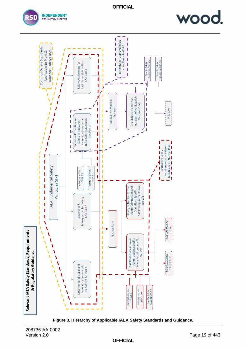
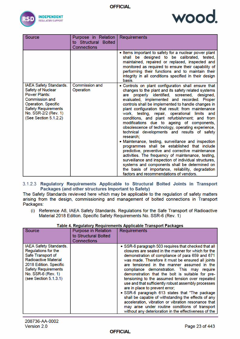
IAEA Safety Standards are tiered down from Fundamental Safety Principles21, through more detailed General Safety Requirements22, which are generally applicable to all nuclear related activities and facilities. Below these are Specific Safety Requirements, which may apply to a particular facility type or activity (such as Nuclear Power Plant or Transport). These requirement documents are supported by non-mandatory guides, which may aid Regulatory Inspectors and Assessors, Licensees, Authorisees or Applicants in interpretation and application. The high level overview of IAEA Safety Standards, which may have some pertinence to the design and execution of structural bolted joints, is shown in Figure 3, with facility / activity applicability and relevant Regulatory Guides. SFR-1 determines the high level safety objectives for all nuclear facilities and activities focussed on the control and mitigation of nuclear risk to personnel, the public and the environment. Detailed requirements are developed down the structure providing the basis for how these objectives are met. For Nuclear Plant, Regulatory Approval requires the demonstration of safety, which is achieved in a holistic manner, recognising the intrinsic dependence of safety on design, manufacturing and management. The design, operation and management of a nuclear facility must satisfy the safety objectives of Fundamental Safety Principles, General Safety Requirements, and any applicable Specific Safety Requirements23, in addition to UK statutory requirements which will be discussed later. For the transport of radioactive materials the process of certification is reduced to more discrete elements for Shipment (Transport Safety) and Design Approvals, where mutual feedback between the requirements is more restricted. The purpose of this is to standardise package design and facilitate transfrontier transport between different regulatory domains. Package Design certification has been typically granted by demonstration of the achievement of performance criteria contained in SSR-624, which are deemed to infer an internationally acceptable level of safety in package design. A full safety case is submitted for regulatory approval during the Application for Shipment Certification and should consider the spectrum of safety and UK statutory requirements, for operation on a UK Licensed Site. Relevant good practice must be selected and applied to demonstrate the Fundamental Safety Principles and Requirements are met.
21 See reference A1 IAEA Safety Standards. Fundamental Safety Principles. Safety Fundamental No. SF-1 (2006) 22 See references A2- A4, IAEA Safety Standards. Governmental, Legal and Regulatory Framework for Safety. General Safety Requirements No. GSR Part 1 (Rev. 1), IAEA Safety Standards. Leadership and Management for Safety. General Safety Requirements No. GSR Part 2 (Rev. 1), IAEA Safety Standards. Radiation Protection and Safety of Radiation Sources: International Basic Safety Standards Part 3. General Safety Requirements No. GSR Part 3. & IAEA Safety Standards. Safety Assessment for Facilities and Activities. General Safety Requirements No. GSR Part 4 (Rev. 1) 23 See references A6 & A7, IAEA Safety Standards. Safety of Nuclear Power Plants: Design. Specific Safety Requirements No. SSR-2/1 (Rev. 1) & IAEA Safety Standards. Safety of Nuclear Power Plants: Commission and Operation. Specific Safety Requirements No. SSR-2/2 (Rev. 1) for example 24 See reference A8 IAEA Safety Standards. Regulations for the Safe Transport of Radioactive Material 2018 Edition. Specific Safety Requirements No. SSR-6 (Rev. 1)
OFFICIAL
208736-AA-0002 Version 2.0
Page 19 of 443
OFFICIAL
Figure 3. Hierarchy of Applicable IAEA Safety Standards and Guidance.


OFFICIAL
208736-AA-0002 Version 2.0
Page 26 of 443
OFFICIAL
Statute Applicable to Transport Activities (CoDG, ADR & RID) The Carriage of Dangerous Goods (Amendment) Regulations 201934 requires those involved in the carriage of dangerous goods in the UK to follow the requirements of RID (for rail) and ADR (for road). ADR35 and RID36 align UK statutory requirements with SSR-6 and explanation from SSG-2637, and compliance is therefore prescriptive.
3.2 Overview of Typical Current Practice
3.2.1 Nuclear Power Plant Boiler Pressure Vessels Global common practices and experience is summarised in greater detail Section 6.5 of this report. Global practice for the design, manufacturing, management, historic failure modes and safety assessment are comprehensively reviewed in IAEA TECDOCs38,39 applicable to PWR and BWR type reactor plants, and further repetition is not necessary. Licensee’s should take note not of the TECDOCs in forming their management arrangements. RPVs and other Class 1 structures tend to receive stringent scrutiny and inspection by Regulatory Bodies and therefore current practice is very closely aligned to code requirements, which are either ASME40 and its subordinate documents or derived local standards. Whenever issues have emerged then practices and management arrangements have evolved to maintain safety. Whenever RGP is updated it is incumbent on the Licensee, via Periodic Safety Review (PSR)41 to “identify deviations between the plant design and current safety requirements and standards (including relevant design codes) and to determine their safety significance”. Alignment to RGP should therefore never deviate for a period longer than the 10 year accepted frequency of PSRs, and this is ensured by the existing regulatory framework.
3.2.2 Transport packages (and Other Structures)
Typical Construction Methods Transport packages, and other Nuclear Structures are constructed from a variety of materials, including:
(i) Structural Steels, typically to BS EN 10025 series or similar;
(ii) Stainless Steels to BS EN 10088 series or similar (including Austenitic and Duplex);
(iii) Aluminium alloys to BS EN 485 series or similar;
(iv) Wood (used for thermal insulation in Transport Packages).
Use of materials other than structural steel is increasingly common. Austenitic stainless steels offer superior environmental corrosion properties, and duplex stainless steels have greater strength and
34 Reference B10, The Carriage of Dangerous Goods and Use of Transportable Pressure Equipment Regulations 2009. Statutory Instruments 2009 No. 1348 35 Reference B11, Economic Commission for Europe Inland Transport Committee. ADR. European Agreement Concerning the International Carriage of Dangerous Goods by Road Volume 1. ECE/TRANS/257 (Vol.I) 36 Reference B12, Convention concerning International Carriage by Rail (COTIF) Appendix C – Regulations concerning the International Carriage of Dangerous Goods by Rail (RID). 2019 37 Reference C6, IAEA Draft Safety Guide. Advisory Material for the IAEA Regulations for the Safe Transport of Radioactive Material (2018 Draft). Specific Safety Guide No. SSG-26. 2018 38 Reference E1, IAEA. Assessment and Management of Ageing of Major Nuclear Power Plant Components Important to Safety: PWR Pressure Vessels 2007 Update. IAEA-TECDOC-1556 39 Reference E2, IAEA. Assessment and management of ageing of major nuclear power plant components important to safety: BWR pressure vessels. IAEA-TECDOC-1470 40 Reference F1, ASME Boiler and Pressure Vessel Code. Subsection NCA General Requirements for Division 1 and Division 2. 2019 41 Reference C8, IAEA Safety Standards. Periodic Safety Review for Nuclear Power Plants. Specific Safety Guide No. SSG-25

OFFICIAL
208736-AA-0002 Version 2.0
Page 27 of 443
OFFICIAL
impact resistance. It is estimated that approximately 85% recent Design Approval Applications or Renewals have containment boundaries or barriers fabricated from stainless steel materials. Construction is typically a combination of casting, forging, fabrication, welding and bolting of discreet components to form containers with closures for containment of radioactive materials. Transport packages may have a number of barriers and closures. Generally, there is an inner receptacle constructed from stainless steel and sealed with a bolted closure (possibly using stainless steel bolts) and an outer package providing shielding, impact, thermal, and water ingress protection. One or more packages may be palletised into a package array. The pallet system is typically from any structural metallic material, including aluminium. There is no consistent standard for quality in manufacture of Transport Packages. The identified requirement in SSR-6 may be derived from paragraph 680(b)(ii) that there should be a “high degree of quality control in the manufacture, maintenance and repair of packagings, coupled with tests to demonstrate closure of each package before each shipment”. Closures in Transport packages typically consist of bolted interfaces in containment boundaries; Bolting materials typically used include:
(i) Carbon and alloy steel bolts to BS 89842, Grade 8.8, 10.9 & 12.9, nuts and washers, or equivalent studs;
(ii) Stainless steel bolts to BS 350643 (Grade A2 or A4);
(iii) Designed and manufactured “special” fasteners. Closures may have additional seals to enhance containment and mitigate heat increase should gapping occur during Accidental Conditions of Transport. Bolts are typically torque tightened to a level claimed to be sufficient to produce the tension and sealing on which the Package Design Approval was based. It is typical, perhaps to lessen the risk of galling, for stainless steel bolts or bolts in stainless steel structures, to be torque-tensioned to some low arbitrary value, to a torque value calculated using rules for steel structures and bolts.
Codes and Standards in Typical Use Typical design standards reflect Transport Container Safety Committee Guidance, particularly TCSC 100644, which is a guide specifically for lifting, tie-down and retention systems of Transport Packages. However, in the absence of any other specific guidance, practice for all structural elements of Packages typically follow the same standards. Typical codes and standards in use are:
(i) BS 2573 Part 1 for structural strength, see Section 5.6.2.1.2;
(ii) BS EN 1993-1-9 or BS 7608 for fatigue, see Sections 5.6.2.1.3 and 5.6.2.1.4; and
(iii) BPVC for containment under elevated temperature and pressure The European Machinery Directive (BS 1300145) is recommended for use by TCSC 1006, when all parts are published, but is not typically used.
42 BRITISH STANDARD. Mechanical properties of fasteners made of carbon steel and alloy steel Part 1: Bolts, screws and studs with specified property classes – Coarse thread and fine pitch thread (ISO 898-1:2013) BS EN ISO 898-1:2013 43 BRITISH STANDARD. Mechanical properties of corrosion-resistant stainless steel fasteners Part 1: Bolts, screws and studs BS EN ISO 3506-1:2009 (under review/draft at 2019) 44 Reference G1, TCSC 1006 Transport of Radioactive Material Code of Practice - Guide to the Securing/Retention of Radioactive Material Payloads and Packages During Transport. July 2018 45 Reference F11 BSI Standards Publication. Cranes - General Design. Part 3-1: Limit States and proof competence of steel structure. BS EN 13001-3-1:2012+A1:2013
OFFICIAL
208736-AA-0002 Version 2.0
Page 28 of 443
OFFICIAL
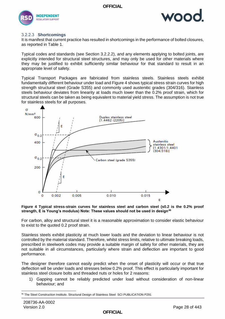
Shortcomings It is manifest that current practice has resulted in shortcomings in the performance of bolted closures, as reported in Table 1. Typical codes and standards (see Section 3.2.2.2), and any elements applying to bolted joints, are explicitly intended for structural steel structures, and may only be used for other materials where they may be justified to exhibit sufficiently similar behaviour for that standard to result in an appropriate level of safety. Typical Transport Packages are fabricated from stainless steels. Stainless steels exhibit fundamentally different behaviour under load and Figure 4 shows typical stress strain curves for high strength structural steel (Grade S355) and commonly used austenitic grades (304/316). Stainless steels behaviour deviates from linearity at loads much lower than the 0.2% proof strain, which for structural steels can be taken as being equivalent to material yield stress. The assumption is not true for stainless steels for all purposes.
Figure 4 Typical stress-strain curves for stainless steel and carbon steel (s0.2 is the 0.2% proof strength, E is Young’s modulus) Note: These values should not be used in design46
For carbon, alloy and structural steel it is a reasonable approximation to consider elastic behaviour to exist to the quoted 0.2 proof strain. Stainless steels exhibit plasticity at much lower loads and the deviation to linear behaviour is not controlled by the material standard. Therefore, whilst stress limits, relative to ultimate breaking loads, prescribed in steelwork codes may provide a suitable margin of safety for other materials, they are not suitable in all circumstances, particularly where strain and deflection are important to good performance. The designer therefore cannot easily predict when the onset of plasticity will occur or that true deflection will be under loads and stresses below 0.2% proof. This effect is particularly important for stainless steel closure bolts and threaded nuts or holes for 2 reasons:
1) Gapping cannot be reliably predicted under load without consideration of non-linear behaviour; and
46 The Steel Construction Institute. Structural Design of Stainless Steel SCI PUBLICATION P291

OFFICIAL
208736-AA-0002 Version 2.0
Page 29 of 443
OFFICIAL
2) Bolts cannot be reliably pre-tensioned. Restriction of bolted joint gapping and control of bolt preload is vital for containment and the performance of transport packages. The standard rules47 for carbon steel bolt tension and tightening do not apply, are not valid, and this is explicit in appropriate RGP48. It is essential that bolts be preloaded to 70% of ultimate breaking strength in order to prevent loosening during fluctuating loading (e.g. transport vibration), and this is not necessarily possible were either the bolt or threaded female nut or hole is comprised of stainless steel. Consequently the possibility of loosening cannot be mitigated. Stainless steel bolts, used in conjunction with stainless steel structures, nuts or threaded holes machined into stainless steel structures, frequently seize by galling, and particularly so at higher preloads. This causes excessive wear, high friction and an extremely unreliable relationship between applied torque and bolt tension, and hence potentially unreliable sealing. The behaviour of stainless steels is not addressed by the currently recommended or applied standards used for Package Design. Without specific reference, it has been noted during regulatory reviews that there has been a number of attempts to apply the standards irrespective of the unsuitability for the package construction materials. Code and standards, currently recommended by TCSC 100649 and in typical use, do not provide appropriate guidance for the most commonly used materials and bolting. BS 2573 Part 1 (1983)50 is superseded, over 35 years old, whilst being very common practice, has very limited advice for the assurance of bolted connections, and cannot be considered current good practice. BS 2573 Part 1 is a structural steel crane code and does not contain any advice pertinent to the unique problems of stainless steel or aluminium construction. Advice for bolts is limited to a recommended tension, which is not feasible for other construction materials and nor does it contain guidance for execution (fastener system selection, quality, tensioning and inspection). To recommend that no better, relevant or more reasonable guidance has superseded BS 2573 Part 1 is not a justifiable or defensible position in that its application does not necessarily achieve the fundamental objectives of
(i) IAEA Safety Standards51 that “standard of safety shall be the highest level that can reasonably achieved”.
(ii) UK ALARP52; and
(iii) Legally binding objectives of SSR-653 “design and manufacturing techniques shall be in accordance with national or international standards, or other requirements, acceptable to the competent authority”.
BS EN 1993-1-9 (fatigue of steel structures) is part of a large suite of Euronorms, which apply to a very broad range of commonly used materials and functions, and which have mutual compatibility.
47 Reference F27, BRITISH STANDARD Guide to design considerations on The strength of screw threads BS 3580:1964 48 Reference F15, BSI Standards Publication. Execution of steel structures and aluminium structures Part 2: Technical requirements for steel structures. BS EN 1090‑2:2018 49 Reference G1, TCSC 1006 Transport of Radioactive Material Code of Practice - Guide to the Securing/Retention of Radioactive Material Payloads and Packages During Transport. July 2018 50 Reference F8, BRITISH STANDARD. Rules for the design of cranes — Part 1: Specification for classification, stress calculations and design criteria for structures. BS 2573-1:1983 51 Reference A1, IAEA Safety Standards. Fundamental Safety Principles. Safety Fundamental No. SF-1 (2006) 52 Reference B2, Health and Safety at Work ect. Act 1974 53 Reference A8, IAEA Safety Standards. Regulations for the Safe Transport of Radioactive Material 2018 Edition. Specific Safety Requirements No. SSR-6 (Rev. 1)
OFFICIAL
208736-AA-0002 Version 2.0
Page 30 of 443
OFFICIAL
The application BS EN 1993-1-954 requires execution and quality of structures to be of the quality and in accordance specified in other Euronorms. It should therefore not be used in isolation and it is not good practice to apply it in conjunction with BS 2573 Part 1.
3.3 Recommendations for RGP Applicable to Bolted Joints
3.3.1 Considerations in Identification of Most Appropriate RGP
Regulatory requirements, arising from IAEA Safety Standards, for RGP have been identified in Sections 5.1.1, 5.1.2 and 5.1.3, all of which may be relevant. The key salient requirements across all IAEA Safety Standards are:
(i) The standard of safety shall be the highest level that can reasonably achieved55. (Interpretation: the best available codes and standards and Good Practice and performance of bolted joints shall be adopted and standards must be current and maintained);
(ii) The optimisation of protection may be achieved by the proportionate application of relevant good practices55. (Interpretation: good practice should be graded and relevant to the particular characteristics of the SSC);
(iii) The approach should be graded dependent on consequences55. (Interpretation: application of RGP / codes and standards should result in better practices, including quality management of personnel, processes and products, being adopted for higher risk bolted joints);
(iv) Processes and activities shall be effectively managed and documented56. (Interpretation: processes and activities, such as assembly and disassembly of bolted joints should have appropriate quality arrangements specified by RGP / codes and standards);
(v) Uncertainties in safety analysis processes should be bounded by conservatisms57. (Interpretation: RGP / codes and standards should have margins exceeding the possible effect uncertainties and uncontrollable variations, such as variation in bolted joints and sealing);
(vi) Items important to safety for a nuclear power plant shall be designed to be calibrated, tested, maintained, repaired or replaced, inspected and monitored58. (Interpretation: RGP / codes and standards should include through life management requirements for bolted joints);
(vii) Before any shipment Transport package Shipment closures should be checked to conform with the standard specified in the Design Approval59; (Interpretation: transport of radioactive material requires checking of closures in addition to RGP QA processes);
(viii) Transport Package closure bolts shall not loosen59. (Interpretation: RGP / codes and standards must be able to assure that bolts / fasteners must not loosen during Shipment);
54 Reference F13, BRITISH STANDARD. Eurocode 3: Design of steel structures — Part 1-9: Fatigue. BS EN 1993-1-9:2005, Incorporating corrigenda December 2005, September 2006 and April 2009 55 Reference A1, IAEA Safety Standards. Fundamental Safety Principles. Safety Fundamental No. SF-1 (2006) 56 Reference A3, IAEA Safety Standards. Leadership and Management for Safety. General Safety Requirements No. GSR Part 2 (Rev. 1) 57 Reference A5, IAEA Safety Standards. Safety Assessment for Facilities and Activities. General Safety Requirements No. GSR Part 4 (Rev. 1) 58 Reference A6, IAEA Safety Standards. Safety of Nuclear Power Plants: Design. Specific Safety Requirements No. SSR-2/1 (Rev. 1) 59 Reference A8, IAEA Safety Standards. Regulations for the Safe Transport of Radioactive Material 2018 Edition. Specific Safety Requirements No. SSR-6 (Rev. 1)
OFFICIAL
208736-AA-0002 Version 2.0
Page 31 of 443
OFFICIAL
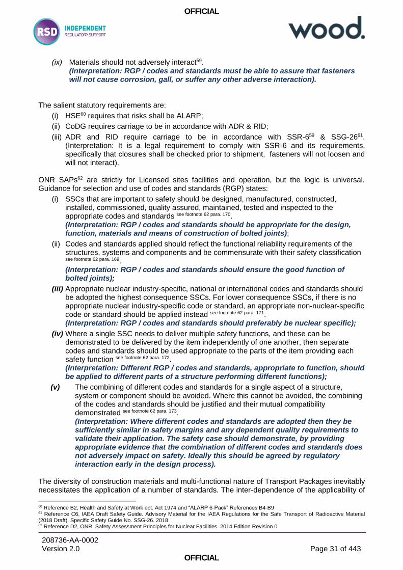
(ix) Materials should not adversely interact59. (Interpretation: RGP / codes and standards must be able to assure that fasteners will not cause corrosion, gall, or suffer any other adverse interaction).
The salient statutory requirements are:
(i) HSE60 requires that risks shall be ALARP;
(ii) CoDG requires carriage to be in accordance with ADR & RID;
(iii) ADR and RID require carriage to be in accordance with SSR-659 & SSG-2661. (Interpretation: It is a legal requirement to comply with SSR-6 and its requirements, specifically that closures shall be checked prior to shipment, fasteners will not loosen and will not interact).
ONR SAPs62 are strictly for Licensed sites facilities and operation, but the logic is universal. Guidance for selection and use of codes and standards (RGP) states:
(i) SSCs that are important to safety should be designed, manufactured, constructed, installed, commissioned, quality assured, maintained, tested and inspected to the appropriate codes and standards see footnote 62 para. 170. (Interpretation: RGP / codes and standards should be appropriate for the design, function, materials and means of construction of bolted joints);
(ii) Codes and standards applied should reflect the functional reliability requirements of the structures, systems and components and be commensurate with their safety classification see footnote 62 para. 169. (Interpretation: RGP / codes and standards should ensure the good function of bolted joints);
(iii) Appropriate nuclear industry-specific, national or international codes and standards should be adopted the highest consequence SSCs. For lower consequence SSCs, if there is no appropriate nuclear industry-specific code or standard, an appropriate non-nuclear-specific code or standard should be applied instead see footnote 62 para. 171. (Interpretation: RGP / codes and standards should preferably be nuclear specific);
(iv) Where a single SSC needs to deliver multiple safety functions, and these can be demonstrated to be delivered by the item independently of one another, then separate codes and standards should be used appropriate to the parts of the item providing each safety function see footnote 62 para. 172. (Interpretation: Different RGP / codes and standards, appropriate to function, should be applied to different parts of a structure performing different functions);
(v) The combining of different codes and standards for a single aspect of a structure, system or component should be avoided. Where this cannot be avoided, the combining of the codes and standards should be justified and their mutual compatibility demonstrated see footnote 62 para. 173. (Interpretation: Where different codes and standards are adopted then they be sufficiently similar in safety margins and any dependent quality requirements to validate their application. The safety case should demonstrate, by providing appropriate evidence that the combination of different codes and standards does not adversely impact on safety. Ideally this should be agreed by regulatory interaction early in the design process).
The diversity of construction materials and multi-functional nature of Transport Packages inevitably necessitates the application of a number of standards. The inter-dependence of the applicability of
60 Reference B2, Health and Safety at Work ect. Act 1974 and “ALARP 6-Pack” References B4-B9 61 Reference C6, IAEA Draft Safety Guide. Advisory Material for the IAEA Regulations for the Safe Transport of Radioactive Material (2018 Draft). Specific Safety Guide No. SSG-26. 2018 62 Reference D2, ONR. Safety Assessment Principles for Nuclear Facilities. 2014 Edition Revision 0

OFFICIAL
208736-AA-0002 Version 2.0
Page 32 of 443
OFFICIAL
codes, and the necessity of a common manufacturing and inspection quality requirement strongly favours the selection of a suite of standards, with sub-divisions specialised in function and/or material, which are mutually compatible. The requirements for RGP and conclusions pertaining to good behaviour and good performance of bolted connections are inseparable from the requirements for broader structural integrity. The selection of a suite of documents is therefore highly advantageous for ALARP.
3.3.2 Recommendations for RGP Applicable to Bolted Joints Important to Safety for RPV Applications
Current practice is closely aligned to Good Practice, compliance is frequently reviewed against emergent practice, and application receives close regulatory scrutiny. Historical reliability is good and where issues have occurred they have been rectified without radiological consequences. Recommendation to change practice could only risk undermining safety by the introduction of incompatible standards. Therefore there is no recommendation to alter RGP for Nuclear power Plant Closure bolts / studs.
3.3.3 Recommendations for RGP Applicable to Bolted Joints Important to Safety for Transport and Other Applications
The following text is from BSI publications63:
The Eurocodes are seen as leading the way in structural codes. Their flexibility enables adoption and use not only within Europe, but internationally. This feature has been recognized by several countries outside Europe and they are already committed to adopting Eurocodes. The primary objectives of the Eurocodes are to:
Provide common design criteria and methods of meeting necessary requirements for mechanical resistance, stability and resistance to fire, including aspects of durability and economy
Provide a common understanding regarding the design of structures between owners, operators and users, designers, contractors and manufacturers of construction products
Facilitate the marketing and use of structural components and kits in EU Members States
Facilitate the marketing and use of materials and constituent products, the properties of which enter into design calculations
Be a common basis for research and development, in the construction industry
Allow the preparation of common design aids and software
Increase the competitiveness of the European civil engineering firms, contractors, designers and product manufacturers in their global activities.
The Eurocodes are designed to be used as a suite of documents, which means that for most projects more than one code will be needed e.g. BS EN 1990 is always required. In addition, Eurocodes are designed to be used with a National Annex, which is available separately but which is essential for compliance with the Code. Other documents required for using Eurocodes are the so-called Non-Contradictory Complementary Information (NCCI) which includes BSI Standards and PD documents. The status of these documents can vary. As the name suggests they provide supplementary material that may be useful but are not always essential for compliance with the Eurocodes.
63 BSI Website: https://shop.bsigroup.com/Browse-By-Subject/Eurocodes/
OFFICIAL
208736-AA-0002 Version 2.0
Page 33 of 443
OFFICIAL
Other documents include Execution Standards, which provide requirements for execution of structures that have been designed to Eurocodes. BSI committees have stopped updating the British Standards that were withdrawn on the 31st of March 2010, so designers need to be mindful of insurance and liability issues if they continue to use them. The objectives of the Eurocode suite match very closely with those for nuclear safety, and requirements for, structural integrity, serviceability, impact, human error, hazard avoidance, reliability management, execution, inspection and durability. Recommendation: Design and execution of Bolted Joints, and Structural Integrity as a whole, should follow the rule developed in the Eurocode suite.
New Transport Packages and Facilities (not Pressure Retaining Nuclear Plant) - High Level RGP for Structural Design and Design of Bolted Joints
Specific Eurocodes for design are referenced dependent on action or construction material:
EN 1991 Eurocode 1: Actions on structures
EN 1992 Eurocode 2: Design of concrete structures
EN 1993 Eurocode 3: Design of steel structures
EN 1994 Eurocode 4: Design of composite steel and concrete structures
EN 1995 Eurocode 5: Design of timber structures
EN 1996 Eurocode 6: Design of masonry structures
EN 1997 Eurocode 7: Geotechnical design
EN 1998 Eurocode 8: Design of structures for earthquake resistance
EN 1999 Eurocode 9: Design of aluminium structures Each of the Eurocodes have a number of Parts, for example BS EN 1993 is divided into:
EN 1993-1-1 Design of Steel Structures: General rules and rules for buildings.
EN 1993-1-2 Design of Steel Structures: Structural fire design.
EN 1993-1-3 Design of Steel Structures: Cold-formed members and sheeting.
EN 1993-1-4 Design of Steel Structures: Stainless steels.
EN 1993-1-5 Design of Steel Structures: Plated structural elements.
EN 1993-1-6 Design of Steel Structures: Strength and stability of shell structures.
EN 1993-1-7 Design of Steel Structures: Strength and stability of planar plated structures transversely loaded.
EN 1993-1-8 Design of Steel Structures: Design of joints.
EN 1993-1-9 Design of Steel Structures: Fatigue strength of steel structures.
EN 1993-1-10 Design of Steel Structures: Selection of steel for fracture toughness and through-thickness properties.
EN 1993-1-11 Design of Steel Structures: Design of structures with tension components made of steel.
EN 1993-1-12 Design of Steel Structures: Supplementary rules for high strength steel.
The Eurocode suite forms a complete and comprehensive guide to the design of structures, containing detailed advice appropriate to type of structure, construction materials, construction method, load action and environment. BS EN 1993-1-864 is a gateway to detailed requirements for the design and structural integrity of connections, but requires compliance be demonstrated to other applicable standards in the suite.
64 Reference F12, BRITISH STANDARD. Eurocode 3: Design of steel structures — Part 1-8: Design of joints. BS EN 1993-1-8:2005
OFFICIAL
208736-AA-0002 Version 2.0
Page 34 of 443
OFFICIAL
Complementing the structural design codes is BS EN 1090-1/2/3. BS EN 1090-265 contains detailed guidance for the delivery of high quality structural bolted connections that can be assured to meet design requirements. Figure 3 is a simplified high level overview of the tree of Eurocodes, with specific consideration of common construction materials comprising Transport Packages. The standards are branched into detailed requirements, depending on the consequences of material choices and load actions. As previously stated (without specific reference) the most common material of construction used for the fabrication of Transport Packages is stainless steel (frequently 304L), and this is understandably preferred for corrosion resistance. By necessity of the containment function Transport packages consist of receptacles and outer packaging, which may be sealed by bolted closures. Sealing requires packages to resist internal and external pressures and therefore sealing and closure tightness must be assured by bolt tensioning. Transport (Routine and Normal) loading is multi-axial and fluctuating and therefore imposes separating tensile loading on closures. Impact loading (Accidental Conditions) may impose violent loads separating the closures. The functional requirements of Transport are at odds, in some respects, with the capabilities and RGP of stainless steel bolted joints. Stainless steel bolted joints (either stainless steel fabrications, bolts, nuts or threaded holes) are generally:
not considered suitable for tensile loading66, which is essential to resist Transport Loads; and
not recommended for pre-loading (to 70% of ultimate breaking load67), which is essential for:
o Containment; and
o Prevention of loosening68 Carbon steel bolts should not be used for stainless structures69, and hence may not normally be used as a solution to pre-tensioning. The designer and Applicant have a quandary of mutually exclusive requirements, and some compromise is inevitable if stainless steel is a necessity for corrosion purposes. The decision making process in making design choices, as well as any further ALARP measures to minimise residual risk, should form a clear part of any justification and be available to regulators. Figure 3 shows the RGP for bolting, depending on construction material, loading and bolting requirements.
65 Reference F15, BSI Standards Publication. Execution of steel structures and aluminium structures Part 2: Technical requirements for steel structures. BS EN 1090‑2:2018 66 Reference F15, BSI Standards Publication. Execution of steel structures and aluminium structures Part 2: Technical requirements for steel structures. BS EN 1090‑2:2018, Section 5.6.4 67 Reference F12, BRITISH STANDARD. Eurocode 3: Design of steel structures — Part 1-8: Design of joints. BS EN 1993-1-8:2005 Section 3.6.1 68 Reference F15, BSI Standards Publication. Execution of steel structures and aluminium structures Part 2: Technical requirements for steel structures. BS EN 1090‑2:2018, Section 8.2.1 69 Reference F15, BSI Standards Publication. Execution of steel structures and aluminium structures Part 2: Technical requirements for steel structures. BS EN 1090‑2:2018, Section 5.6.3
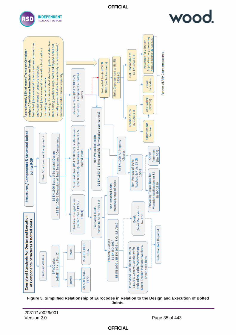
OFFICIAL
203171/0026/001 Version 2.0
Page 35 of 443
OFFICIAL
Figure 5. Simplified Relationship of Eurocodes in Relation to the Design and Execution of Bolted Joints.
OFFICIAL
203171/0026/001 Version 2.0
Page 36 of 443
OFFICIAL
Design and Execution of Bolted Joints and Fastener Systems
Design Design should be in accordance with BS EN 1993-1-870. The key requirements are:
joints should satisfy the design requirements of BS EN 1993-1-1 and be made from structural steel grades;
that non-preloaded (category D) bolted connections: o may use fastener property classes 4.6 up to and including 10.9; o should not be used where the connections are frequently subjected to variations of
tensile loading;
that preloaded bolted (category C) bolted connections: o may use fastener property classes 8.8 and 10.9; o should be assembled using controlled tightening in conformity with 1.2.7; o should conform to design summarised in Table 3.2; o should be preloaded as per 3.6.1 (Fp,Cd = 0,7 fub As / γM7).
Execution of Bolted Joints
Execution should be in accordance with BS EN 1090-271. The key requirements and processes are:
that bolted joints should be classified by Execution Class. For critical bolted joints it is probable that EXC4 will normally be appropriate.
that the materials of bolts and property classes for bolts which generally fall within its rules, by reference to BS EN 14399 all parts) & BS EN 898-2;
that the constructor shall have a written Quality Plan in accordance with Section 4;
that identification, inspection documents and traceability should be as per Section 5.2;
that corrosion protection of fasteners be as per Section 5.6.1: o hot dip galvanized coatings of fasteners shall conform to EN ISO 10684 ; o non-electrolytically applied zinc flake coatings of fasteners shall conform to EN ISO
10683;
that requirements for non-preloaded applications: o carbon steel, alloy steel and stainless steel structural bolting assemblies for non-
preloaded applications shall conform to the requirements of the EN 15048 series or BS EN 14399;
o fasteners according to EN ISO 898-1 and EN ISO 898-2 shall generally not be used to join stainless steels according to the EN 10088-4 and EN 10088-5;
that requirements for preloaded applications: o fasteners shall conform to BS EN 14399 series; o high strength bolting assemblies for preloading shall be used without alteration to the as-
delivered lubrication unless DTI method or the procedure in Annex H is adopted; o stainless steel bolting assemblies shall not be used in preloaded applications
unless otherwise specified. If used they shall be considered as special fasteners;
70 Reference F12, BRITISH STANDARD. Eurocode 3: Design of steel structures — Part 1-8: Design of joints. BS EN 1993-1-8:2005 71 Reference F15, BSI Standards Publication. Execution of steel structures and aluminium structures Part 2: Technical requirements for steel structures. BS EN 1090‑2:2018
OFFICIAL
203171/0026/001 Version 2.0
Page 37 of 443
OFFICIAL
o direct tension indicators according BS EN 14399-9 may be used; o that preloaded assemblies do not require additional locking devices; o that preloaded assemblies should be tightened to 0,7 fub As (70% of ultimate breaking
load); o that torque reference values to be calculated from k-class (a system friction relationship
between torque and tension, supplied by the manufacturer), as per Section 8.5.3 – 8.5.6; o that preloaded assemblies should be tightened to one the methods in Section 8.5:
1) Torque method The bolting assemblies shall be tightened using a torque wrench;
2) Combined method A first step to a specified torque followed by a second step to a part turn;
3) HRC method Using a shear bolt and special shear wrench in accordance with BS EN 14399-10;
4) Direct tension indicator method
Using a special crushable washer and feeler guages in accordance with BS EN 14399-9;
that requirements for locking devices: o for the prevention of loosening, prevailing torque nuts from EN ISO 7040, EN ISO 7042,
EN ISO 7719 and EN ISO 10511 and the performance requirements given in EN ISO 2320 may be used;
o preloaded assemblies do not require additional locking devices;
requirements for Special Fasteners: o resin injection bolts should be considered as special fasteners; o threaded stud or tapped blind holes, stainless steel bolts, tapped holes in stainless steel
structures and lubricants different to the as supplied standard are examples of special fasteners
o suitability for preloading to be demonstrated in accordance with test procedure in Annex H (BS EN 14399-2);
dimensions / execution of holes should be as Section 6.6;
galling and seizure of stainless steels and avoidance of seizure as per Section 8.9: o use of dissimilar stainless steel grades; o anti-galling agents such as PTFE dry film spray; o use of anti-galling grades of stainless steel;
that Inspections: o inspection before tightening as per Execution Class in accordance with Section
12.5.2.3; o inspection of non-preloaded bolted connections as Section 12.5.1; o inspection and testing of preloaded bolted connections:
1) inspection and sampling dependent on Execution Class and Tightening method; 2) torque method as per Section 12.5.2.5 – carried out 12-72 hours after final
completion, torque at least 105% of specification; 3) combined method as per Section 12.5.2.6 – similar to assembly; 4) HRC as per Section as per Section 12.5.2.7; 5) direct tension indicator method as per Section 12.5.2.8;
geometry and materials of bolts, washers and threads which should be considered special and subject to supplementary rules and testing;
rules for non-preloaded connections and pre-loaded connection (shear and tension);
methods for reliable determining target tightening torque for standard property classes and combinations of standard nuts, washers and bolts;

OFFICIAL
203171/0026/001 Version 2.0
Page 38 of 443
OFFICIAL
methods for reliable tightening/tensioning and installation of mechanical fasteners Structures and bolted joints should be classified by Execution Class72. Four execution classes 1 to 4, denoted EXC1 to EXC4, are given, for which requirement strictness increases from EXC1 to EXC3 with EXC4 being based on EXC3 with further project specific requirements. EXC4 is the most rigorous Execution Class and for safety critical nuclear structures it may be reasonable to assume execution as EXC4.
3.3.3.2.1 Quality Execution
The constructor shall have a documented quality plan for execution, including mechanical fasteners, in accordance with BS EN 1090-2 Section 4.273 and ONR NS-TAST-GD-102 Revision 074.
The quality documentation should include:
a) organization chart and managerial staff responsible for each aspect of the execution;
b) the procedures, methods and work instructions to be applied;
c) an inspection and test plan specific to the works;
d) a procedure for handling changes and modifications;
e) a procedure for handling of nonconformities;
f) specified hold-points or requirement to witness inspections or tests, and any consequent access requirements.
A quality plan shall include:
a) a general management document which shall address the following points:
1) review of specification requirements against process capabilities;
2) the allocation of tasks and authority during the various phases of the project;
3) principles and organization arrangements for inspection including allocation of responsibilities for each inspection task;
b) quality documentation prior to execution. The documents shall be produced before execution of the construction step to which they relate;
c) execution records, which are actual records of inspections and checks carried out, or which demonstrate qualification or certification of implemented resources.
Quality documentation should also include “Suitability for pre-loading” for critical bolted connections and fastener systems.
Quality of Fasteners used in Pre-loaded applications
Pre-loaded carbon steel fasteners systems (applying to standard combinations of materials and tribology) in structural steel connections should be purchased compliant to BS EN 14399. Such fasteners are supplied with manufacturer assured friction coefficients, determined using tests by the
72 Reference F15, BSI Standards Publication. Execution of steel structures and aluminium structures Part 2: Technical requirements for steel structures. BS EN 1090‑2:2018 Section 4.1.2 73 Reference F15, BSI Standards Publication. Execution of steel structures and aluminium structures Part 2: Technical requirements for steel structures. BS EN 1090‑2:2018 74 Reference D13, ONR Guide. General Guidance for Mechanical Engineering Specialism Group. Nuclear Safety Technical Assessment Guide NS-TAST-GD-102 Revision 0. January 2019
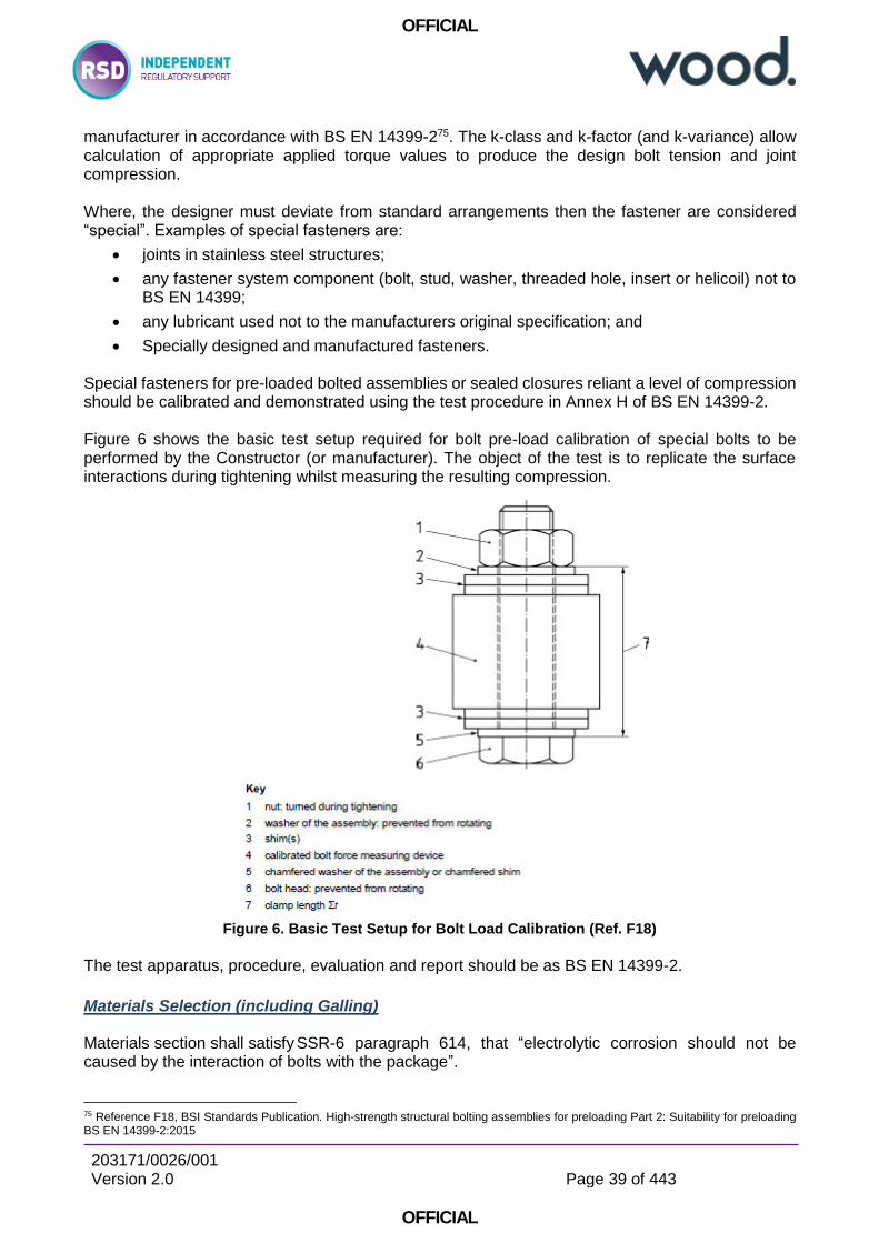
OFFICIAL
203171/0026/001 Version 2.0
Page 39 of 443
OFFICIAL
manufacturer in accordance with BS EN 14399-275. The k-class and k-factor (and k-variance) allow calculation of appropriate applied torque values to produce the design bolt tension and joint compression. Where, the designer must deviate from standard arrangements then the fastener are considered “special”. Examples of special fasteners are:
joints in stainless steel structures;
any fastener system component (bolt, stud, washer, threaded hole, insert or helicoil) not to BS EN 14399;
any lubricant used not to the manufacturers original specification; and
Specially designed and manufactured fasteners.
Special fasteners for pre-loaded bolted assemblies or sealed closures reliant a level of compression should be calibrated and demonstrated using the test procedure in Annex H of BS EN 14399-2. Figure 6 shows the basic test setup required for bolt pre-load calibration of special bolts to be performed by the Constructor (or manufacturer). The object of the test is to replicate the surface interactions during tightening whilst measuring the resulting compression.
Figure 6. Basic Test Setup for Bolt Load Calibration (Ref. F18)
The test apparatus, procedure, evaluation and report should be as BS EN 14399-2.
Materials Selection (including Galling) Materials section shall satisfy SSR-6 paragraph 614, that “electrolytic corrosion should not be caused by the interaction of bolts with the package”.
75 Reference F18, BSI Standards Publication. High-strength structural bolting assemblies for preloading Part 2: Suitability for preloading BS EN 14399-2:2015

OFFICIAL
203171/0026/001 Version 2.0
Page 40 of 443
OFFICIAL
The Applicant or Licensee should make full reference to BS EN 1090-2 and BS EN 14399 for restrictions.
Preloaded structural steel bolted joints Bolting materials selection for pre-loaded joints steel structures should follow the rules in BS1090-2:
a) Fastener systems shall conform to BS EN 14399 series (BS EN 898-2), Grade 8.8 or 10.976;
b) Hot dip galvanized coatings of fasteners shall conform to EN ISO 10684; and
c) Non-electrolytically applied zinc flake coatings of fasteners shall conform to EN ISO 10683.
If Grade 10.9 bolts are selected77:
the manufacturing process for bolts of property class 10.9 shall take due care of the risk of hydrogen embrittlement, especially during the coating process. Appropriate processes shall be considered when the risk of hydrogen embrittlement cannot be avoided; and
bolts of property class 10.9 shall have rolled threads
Non-preloaded or partially-pre-loaded stainless steel bolted joints Fasteners according to EN ISO 898-1 and EN ISO 898-2 shall not be used to join stainless steels according to the EN 10088-4 and EN 10088-5 unless otherwise specified. If insulation kits are to be used full details of their use shall be specified78. When stainless steel bolts are used in combination with stainless threads BS EN 1090-279 advises: Galling may result from local adhesion and rupture of surfaces under load and in relative motion during fastening of stainless steel bolts. In some cases, weld bonding and seizure may result.
The following methods may be used to avoid galling problems:
a) dissimilar standard grades of stainless steel may be used which vary in work hardening rate and hardness (e.g. Grade A4-50/A4-80 bolt-nut combination from EN ISO 3506-1 and EN ISO 3506-2);
b) in severe cases, a proprietary high work-hardening stainless steel alloy may be used for one component or hard surface coatings applied so that the hardness of the contact surfaces differs by at least 30 HV10, e.g. nitriding or hard chromium plating;
c) anti-galling agents such as PTFE dry film spray;
d) use an anti-galling grade of stainless steel (such as S21800) for one or both of the mating surfaces.
If dissimilar metals or coatings are used, it is necessary to ensure that the required corrosion resistance is obtained. Non-preloaded stainless steel bolts shall conform to BS EN 1504880 series, but are considered out of scope as generally all critical joints require pre-tensioning.
76 Grade 12 is permitted by BS EN 13001 for lifting application providing that hydrogen embrittlement is assessed 77 Reference F18, BSI Standards Publication. High-strength structural bolting assemblies for preloading Part 2: Suitability for preloading BS EN 14399-2:2015, Section 5.1 78 Reference F15, BSI Standards Publication. Execution of steel structures and aluminium structures Part 2: Technical requirements for steel structures. BS EN 1090‑2:2018, Section 5.6.3 79 Reference F15, BSI Standards Publication. Execution of steel structures and aluminium structures Part 2: Technical requirements for steel structures. BS EN 1090‑2:2018, Section 8.9 80 Reference F24, BSI Standards Publication. Non-preloaded structural bolting assemblies Part 1: General requirements BS EN 15048-1:2016

OFFICIAL
203171/0026/001 Version 2.0
Page 41 of 443
OFFICIAL
TCSC 3181 provides advice on alternative thread forms and other measures which aid in the prevention of Galling.
Elements of Fastener Systems To prevent loosening bolts are tensioned to a load above that the elastic range of the fastener system and induce ductility. System HV is used in Germany and use thinner nuts and shorter thread lengths to obtain the required ductility by plastic deformation of the threads within the nut. System HR is used in the UK use thick nuts and long thread lengths in the bolt assembly to obtain ductility predominantly by plastic elongation of the bolt. BS EN 14399 forms a suite of harmonised standards governing the use of high strength bolts:
EN 14399-2:2015, is a guide determining the suitability for preloading, including test methods for demonstrating the torque-tension relation with variation;
EN 14399-3:2015, is a guide for the specifications of System HR – Hexagon bolt and nut assemblies, commonly used in the UK;
EN 14399-4:2015, is a guide for System HV – Hexagon bolt and nut assemblies, not commonly used in the UK;
EN 14399-5, is a guide for the specification of Plain washers;
EN 14399-6, is a guide for the specification of Plain chamfered washers;
EN 14399-7:2007, is a guide for the specification of System HR - Countersunk head bolt and nut assemblies, not commonly used in nuclear applications;
EN 14399-8:2007, is a guide for the specification of System HV - Hexagon fit bolt and nut assemblies, not commonly used in the UK;
EN 14399-9:2009, is a guide for the specification of System HR or HV - Direct tension indicators for bolt and nut assemblies;
EN 14399-10:2009, is a guide for the specification of System HRC – Bolt and nut assemblies with calibrated preload;
Hexagonal bolt and nut assemblies (to BS EN 14399-3) and Plain washers (to BS EN 14300-5/6) encompass what may be considered standard bolting systems in the UK., for use in pre-tensioned structural steel bolted joints. They are calibrated by the manufacturer and may be reliably used in joints where pre-load is critical and their use should be preferable wherever possible.
3.3.3.3.1 Direct tension indicators Direct tension indicators (known formerly as load indicating washers) used in conjunction with nut face washers (HN) and bolt face washers (HB) are load indicating devices which are placed under the bolt head or under the nut. The direct tension indicators have protrusions on one face which compress under load and thus may be used to indicate that at least the required preload has been achieved in the bolting assembly.
81 Reference G2, TCSC 31 Transport of Radioactive Material Code of Practice - Design and Operation to Minimise Seizure of Fasteners. June 2014, Section 3
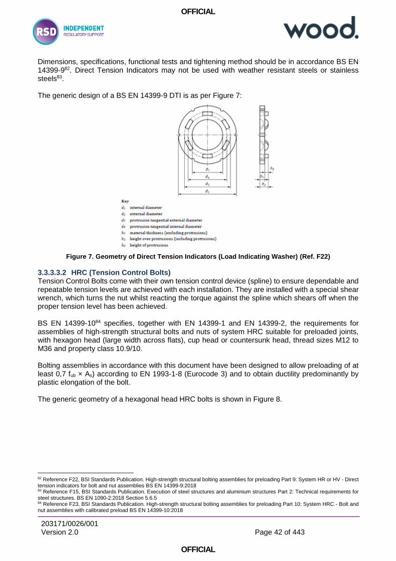
OFFICIAL
203171/0026/001 Version 2.0
Page 42 of 443
OFFICIAL
Dimensions, specifications, functional tests and tightening method should be in accordance BS EN 14399-982. Direct Tension Indicators may not be used with weather resistant steels or stainless steels83. The generic design of a BS EN 14399-9 DTI is as per Figure 7:
Figure 7. Geometry of Direct Tension Indicators (Load Indicating Washer) (Ref. F22)
3.3.3.3.2 HRC (Tension Control Bolts) Tension Control Bolts come with their own tension control device (spline) to ensure dependable and repeatable tension levels are achieved with each installation. They are installed with a special shear wrench, which turns the nut whilst reacting the torque against the spline which shears off when the proper tension level has been achieved. BS EN 14399-1084 specifies, together with EN 14399-1 and EN 14399-2, the requirements for assemblies of high-strength structural bolts and nuts of system HRC suitable for preloaded joints, with hexagon head (large width across flats), cup head or countersunk head, thread sizes M12 to M36 and property class 10.9/10. Bolting assemblies in accordance with this document have been designed to allow preloading of at least 0,7 fub × As) according to EN 1993-1-8 (Eurocode 3) and to obtain ductility predominantly by plastic elongation of the bolt. The generic geometry of a hexagonal head HRC bolts is shown in Figure 8.
82 Reference F22, BSI Standards Publication. High-strength structural bolting assemblies for preloading Part 9: System HR or HV - Direct tension indicators for bolt and nut assemblies BS EN 14399-9:2018 83 Reference F15, BSI Standards Publication. Execution of steel structures and aluminium structures Part 2: Technical requirements for steel structures. BS EN 1090‑2:2018 Section 5.6.5 84 Reference F23, BSI Standards Publication. High-strength structural bolting assemblies for preloading Part 10: System HRC - Bolt and nut assemblies with calibrated preload BS EN 14399-10:2018
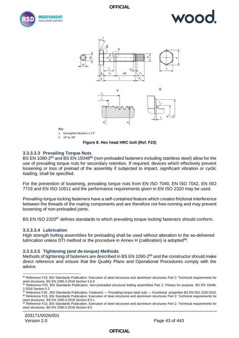
OFFICIAL
203171/0026/001 Version 2.0
Page 43 of 443
OFFICIAL
Figure 8. Hex head HRC bolt (Ref. F23)
3.3.3.3.3 Prevailing Torque Nuts BS EN 1090-285 and BS EN 1504886 (non-preloaded fasteners including stainless steel) allow for the use of prevailing torque nuts for secondary retention. If required, devices which effectively prevent loosening or loss of preload of the assembly if subjected to impact, significant vibration or cyclic loading, shall be specified. For the prevention of loosening, prevailing torque nuts from EN ISO 7040, EN ISO 7042, EN ISO 7719 and EN ISO 10511 and the performance requirements given in EN ISO 2320 may be used. Prevailing-torque locking fasteners have a self-contained feature which creates frictional interference between the threads of the mating components and are therefore not free-running and may prevent loosening of non-preloaded joints. BS EN ISO 232087 defines standards to which prevailing torque locking fasteners should conform.
3.3.3.3.4 Lubrication High strength bolting assemblies for preloading shall be used without alteration to the as-delivered lubrication unless DTI method or the procedure in Annex H (calibration) is adopted88.
3.3.3.3.5 Tightening (and de-torque) Methods Methods of tightening of fasteners are described in BS EN 1090-289 and the constructor should make direct reference and ensure that the Quality Plans and Operational Procedures comply with the advice.
85 Reference F15, BSI Standards Publication. Execution of steel structures and aluminium structures Part 2: Technical requirements for steel structures. BS EN 1090‑2:2018 Section 5.6.8 86 Reference F25, BSI Standards Publication. Non-preloaded structural bolting assemblies Part 2: Fitness for purpose. BS EN 15048-2:2016 Section 5.2 87 Reference F26 , BSI Standards Publication. Fasteners — Prevailing torque steel nuts — Functional properties BS EN ISO 2320:2015 88 Reference F15, BSI Standards Publication. Execution of steel structures and aluminium structures Part 2: Technical requirements for steel structures. BS EN 1090‑2:2018 Section 8.5.1 89 Reference F15, BSI Standards Publication. Execution of steel structures and aluminium structures Part 2: Technical requirements for steel structures. BS EN 1090‑2:2018 Section 8.5
OFFICIAL
203171/0026/001 Version 2.0
Page 44 of 443
OFFICIAL
Non-preloaded joints are generally assembled “wrench tight”.
3.3.3.3.6 Pre-tensioned joints BS EN 1090-290 advises that unless otherwise specified, the nominal minimum preloading force Fp,C
shall be taken as:
Fp,C = 0,7 fub As
where
fub is the nominal ultimate strength of the bolt material as defined in EN 1993-1-8 As is the stress area of the bolt.
The Torque Reference Value should be calculated as follows:
a) values based on k-class declared by the fastener manufacturer in accordance with the relevant parts of the EN 14399 series:
1) Mr,2 = km d Fp,C with km for k-class K2;
2) Mr,1 = 0,125 d Fp,C for k-class K1.
b) values determined according to Annex H (pre-load calibration): Mr,test = Mm with Mm determined according to the procedure relevant to the tightening method to be used.
Pre-loaded bolting assemblies, of any Execution Class, can be tightened using one of the appropriate methods in BS EN 1090-2:
1) Torque method - The bolting assemblies shall be tightened using a calibrated torque wrench
2) Combined method – a first step to a specified torque followed by a second step to a part turn
3) Direct tension indicator method – using a special crushable washer and feeler gauges in accordance with BS EN 14399-9
4) HRC method – using a shear bolt and special shear wrench in accordance with BS EN 14399-10
TCSC 31 advises on the usefulness of measuring and recording torque to undo91 during disassembly. Pre-loaded bolting assemblies, or any fastener tensioned to achieve a specified level, should be discarded in disassembly and not reused.
3.3.3.3.7 Other ALARP counter-measures In some circumstances, particularly where bolts are not pre-tensionable to the specified level in BS EN 1090-2, and where torque-prevailing nuts may not be used (such hex-bolts screwed into threaded holes in stainless steel structures), then further ALARP measures may be necessary to the reduce risk of loosening under vibration loading. Other engineered safety measures, such as wire locking, tabbed washers or visual indicating caps92 may be considered, in addition to other secondary retention measures.
90 Reference F15, BSI Standards Publication. Execution of steel structures and aluminium structures Part 2: Technical requirements for steel structures. BS EN 1090‑2:2018 Section 8.5.2 91 Reference G2, TCSC 31 Transport of Radioactive Material Code of Practice - Design and Operation to Minimise Seizure of Fasteners. June 2014 Section 5 92 Reference H2, Transport Research laboratory. Heavy vehicle wheel detachment and possible solutions Phase 2 – final report PPR475 2010
OFFICIAL
203171/0026/001 Version 2.0
Page 45 of 443
OFFICIAL
Inspection
3.3.3.4.1 General Requirements Inspection shall satisfy the requirements of SSR-6 paragraph 503 that “it shall be ensured by inspection and/or appropriate tests that all closures, valves and other openings of the containment system through which the radioactive contents might escape are properly closed and, where appropriate, sealed in the manner for which the demonstrations of compliance with the requirements of paras 659 and 671 were made” Prior to assembly an inspection should satisfy the guidance in ONR NS-TAST-GD-10293 Appendix A1.2.4 that licensee’s EIMT schedule(s) should at least inspect for:
surface corrosion on bolts and corrosion of the surrounding parent material(s);
signs of fatigue e.g. bolts identified as “loose” when previously they should have been tightened appropriately;
signs of gapping or “nicks” in threads and equally, checks to determine if bolts have yielded;
where safety critical bolts are used in structural applications, a suitable methodology for in-service inspection or planned replacement strategy should be provided by the licensee; and
where fasteners have “failed” or have been replaced due to signs of yielding or fatigue, then the licensee should have in place a process whereby the faster(s) are tested to identify the failure mode. This information should be used to determine whether “lots” are failing or whether failures are one-offs. The investigation should include an assessment of potential causes and contributory factors to ensure LFE is collated and where appropriate passed on to other plants.
In contradiction to ONR NS-TAST-GD-102, BS EN 1090-294 recommends that:
If a bolting assembly has been tightened to the minimum preload… and is later un-tightened, it shall be removed and the whole assembly shall be discarded. Therefore inspection of threads of bolts or nuts for re-use is nugatory in the case of most bolts in critical closures. Where threads have been cut into blind holes in the structure then the advice in ONR NS-TAST-GD-102should be followed. Additionally prior to assembly an inspection should be documented and satisfy the requirements of BS EN 1090-2 Section 12.5.2.3:
surfaces shall be visually checked immediately before assembly. Acceptance criteria shall be in accordance with 8.4.;
3.3.3.4.2 Pre-service or pre-shipment inspection To satisfy (statutory) requirements before each shipment “for each Type B(U), Type B(M) and Type C package, it shall be ensured by inspection and/or appropriate tests that all closures, valves and other openings of the containment system through which the radioactive contents might escape are properly closed and, where appropriate, sealed in the manner for which the demonstrations of compliance with the requirements of paras 659 and 671 were made”95
93 Reference D13, ONR Guide. General Guidance for Mechanical Engineering Specialism Group. Nuclear Safety Technical Assessment Guide NS-TAST-GD-102 Revision 0. January 2019 94 Reference F15, BSI Standards Publication. Execution of steel structures and aluminium structures Part 2: Technical requirements for steel structures. BS EN 1090‑2:2018 Section 8.5.1 95 Reference A8, IAEA Safety Standards. Regulations for the Safe Transport of Radioactive Material 2018 Edition. Specific Safety Requirements No. SSR-6 (Rev. 1) paragraph 503
OFFICIAL
203171/0026/001 Version 2.0
Page 46 of 443
OFFICIAL
SSG-2696 broadly provides guidance and recommendations for the development of leak tightness tests designed to confirm containment. Such tests are not intended to confirm correct tensioning of joints or that containment will be as designed during Accidental Conditions – just that leakage is within limits prior to shipment. SSG-26 does advise that “before each shipment, the consignor should ensure that the package has been prepared for shipment in compliance with the applicable provisions of the Transport Regulations and the relevant certificate of approval”. Fasteners being correctly tensioned are critical to impact performance and compliance to the conditions assumed in the justification of Accidental Conditions of Transport, in addition to the prevention of loosening. BS 1090-297 specifies rules for inspection for non-preloaded and pre-loaded joints and should form the basis of the written inspection plan. The rigour of the inspection regime depends on the Execution Class. Non-preloaded bolts should be visually inspected. The Applicant or Licensee should make direct reference to the standards. The method of inspection for all critical closures should be as per the original assembly process and available methods are summarised:
1) The Torque Method The inspection of a bolting assembly shall be carried out, using Table 25, by the application of a torque to the nut (or to the bolt head if specified) using a calibrated torque wrench. The objective is to check that the torque value necessary to initiate rotation is at least equal to 1,05 times the torque value Mr,i (i.e Mr,2 or Mr, test). Caution shall be taken to keep the rotation to a strict minimum. The inspection shall be carried out between 12 h and 72 h after final completion of tightening in the bolt subgroup concerned
2) The Combined Method For EXC3 and EXC4 the first step shall be checked before marking using the same torque conditions as used to reach the 75 % condition. A nut, which turns by more than 15° by the application of the inspecting torque, shall be retightened.
3) The HRC Method For EXC2, EXC3 and EXC4 the first tightening step shall be checked by visual inspection of connections to ensure they are fully packed. The inspection shall be carried out on 100 % of the bolting assemblies by visual inspection. Fully tightened bolting assemblies are identified as those with the spline end sheared off. A bolting assembly for which the spline end remains is considered to be under-tightened.
4) Direct Tension Indicator Method After the first step, connections shall be inspected to ensure that they are properly packed in accordance with the tightening procedure. The local alignment of non-conforming connections shall be corrected before final tightening commences. After final tightening, assemblies selected for inspection shall be checked to establish that the final indicator settings are in accordance with the requirements in EN 14399-9. The visual inspection shall include a check to identify any indicators that exhibit full compression of the indicator.
96 Reference C6, IAEA Draft Safety Guide. Advisory Material for the IAEA Regulations for the Safe Transport of Radioactive Material (2018 Draft). Specific Safety Guide No. SSG-26. 2018, paragraphs 97 Reference F15, BSI Standards Publication. Execution of steel structures and aluminium structures Part 2: Technical requirements for steel structures. BS EN 1090‑2:2018 Section 12.5
OFFICIAL
203171/0026/001 Version 2.0
Page 47 of 443
OFFICIAL
Inspections should be carried out between 12 and 72 hours after initial assembly, and in the absence of any relaxation mechanisms then this may be acceptable as satisfying the pre-shipment requirements of SSR-6, if stored for a short period. Sampling of inspection is recommended to be 10% of the total number of bolts for the Torque Method. However, if there is a low tolerance to failure (i.e. no demonstrated redundancy), and dose rate to operators is acceptable, then a greater number maybe be required to satisfy pre-shipment inspection requirements of SSR-6. If there is no redundancy demonstrated in the safety case then 100% inspection would be appropriate.
Parts of Transport Packages (or other SSCs) Performing Lifting Functions TCSC 100698 advises that “BS 2573 will be replaced by BS EN 13001 when all parts are published”. See Section 5.6.2.1.2 for a review and details of BS EN 13001, which is broadly similar to and consistent with the requirements of the rest of the Eurocode suite. The current status (at time of writing) of BS EN 13001 is as follows:
General design Part 1: General principles and requirements [Issued];
General design Part 2: Load actions [Issued, under draft revision];
General Design Part 3-1: Limit States and proof competence of steel structure[Issued];
General design Part 3-2: Limit states and proof of competence of wire ropes in reeving systems [Draft];
General design Part 3-3: Limit states and proof of competence of wheel/rail contacts [Issued];
General design Part 3-4: Limit states and proof of competence of machinery — Bearings [Issued];
General design Part 3-5: Limit states and proof of competence of forged hooks [Issued];
General design Part 3-6: Limit states and proof of competence of machinery — Hydraulic Cylinders [Issued];
General design Part 3-8: Limit states and proof competence of machinery — Shafts [Enquiry stage].
There are no parts of BS EN 13001 remaining unpublished that would prevent the use of BS EN 13001 for Transport Package lifting elements. The need for adoption of consistent codes (in accordance with Fundamental Safety Principles and ONR SAPs) and standards should take precedence and BS EN 13001 and its sub-divisions should be used for elements of Transport Packages performing a lifting function. BS EN 13001 should be applied to elements of Transport Package SSCs which perform lifting functions.
Existing Transport Packages (Renewal Applications) and Facilities (not Pressure Retaining Nuclear Plant)
For Nuclear Power Plant99 it is necessary for the licensee to conduct a Periodic Safety Review to “identify deviations between the plant design and current safety requirements and standards (including relevant design codes) and to determine their safety significance”.
98 Reference G1, TCSC 1006 Transport of Radioactive Material Code of Practice - Guide to the Securing/Retention of Radioactive Material Payloads and Packages During Transport. July 2018 Section 3.3 99 Reference C8, IAEA Safety Standards. Periodic Safety Review for Nuclear Power Plants. Specific Safety Guide No. SSG-25
OFFICIAL
203171/0026/001 Version 2.0
Page 48 of 443
OFFICIAL
For a Renewal Applications100 (every 5 years), it is incumbent on the Applicant to also conduct a PSR. PSRs should identify any shortfalls against new relevant standards. The review of safety factors should identify findings of the following types:
Positive findings (that is, strengths): Where current practice is equivalent to good practices as established in current codes and standards, etc.
Negative findings (that is, deviations): Where current practices are not of a standard equivalent to current codes and standards or industry practices, or do not meet the current licensing basis, or are inconsistent with operational documentation for the plant or operating procedures.
In the case of general structural requirements, BS 2573 Part 1, is generally more onerous than BS EN 13001, due to its larger combined factors on stress and load actions, and therefore should not in the majority of cases prevent renewal. PSR against bolting practices to updated RGP might identify very real shortfalls in the safety of bolted joints and fastener systems (consistent with the frequency of reported incidents), particularly:
for non-structural steel package designs;
where bolts are not tensioned to the normal tension to prevent loosening; and
where bolting assemblies use non-standard (equivalent to BS EN 14399) elements, such threaded holes, inserts or helicoils.
Should shortfalls identified then NS-TAST-GD-102101 provides useful guidance: A2.1.1.32 It is recognised that application of all of the above elements will prove challenging to long-established licensee’s where such requirements are new. In such cases, a proportionate approach should be taken to provide confidence that the safety critical application of fasteners has been carried out in a manner that reduces the risk of failure to as low as reasonably practicable (ALARP) levels. A2.1.1.33 Inspectors may be presented with less evidence, but undertake a more detailed discussion with a number of personnel in order to satisfy themselves, or inspectors may require the licensee to provide a report identifying why their arrangements have met RGP. The argument “they haven’t failed yet” is not sufficient, however, evidence to show that the fasteners used are sufficiently robust, are inspected on a regular basis and samples have been tested to show that they meet the design intent may satisfy the inspector. A2.1.1.34 The inspector should seek to advise the licensee that for future supply of safety critical fasteners, a more up-to-date and robust system for specification, auditing, receipt, storage and use should be applied. Such changes should not overly affect the established practices of the licensee; however, necessary changes may take time to implement.
100 ONR. GUIDANCE FOR APPLICATIONS FOR UK COMPETENT AUTHORITY APPROVAL TRA-PER-GD-014 Revision 2. June 2019, Section 4.6 101 Reference D13, ONR Guide. General Guidance for Mechanical Engineering Specialism Group. Nuclear Safety Technical Assessment Guide NS-TAST-GD-102 Revision 0. January 2019 Section A1.2.7

OFFICIAL
203171/0026/001 Version 2.0
Page 49 of 443
OFFICIAL
4 Conclusions
It is concluded that current RGP for Nuclear Power Plant is already closely aligned with applicable and relevant RGP. For Transport Packages (and other structures) it is difficult to separate the requirements for RGP for bolted connections and structural integrity as a whole. The need for consistency and compatibility of standards is paramount, and performance and suitability of bolts depends on the structure and its construction materials. Current practice has its roots in recommendations made by the Transport Container Safety Committee and particularly in TCSC 1006. The design code recommended therein102 is concise and relatively straight forward to apply, at least partly because it is restricted to cranes and structural steel materials. It is precisely because of this that it is not necessarily suitable for the full range of metallic construction materials actually used, and for bolting in those materials. Code and standards should not be used in isolation or by “pick-and-mix” because of needs of compatibility and consistency of safety margins. The recommendations for RGP apply equally to all aspects of structural integrity for transport Packages, and the rationale applies to all structures other than those to which BPVC would apply. It is concluded that typical current practice, as recommended by TSCSC 1006103, is unsuitable for application to the range of construction and bolting materials in actual use for typical Transport Packages. The use of stainless steels has some mutually exclusive requirements with the codes and standards currently typically used, particularly in the ability to ensure bolt tension meets levels assumed in the compliance to containment requirements in Accidental Conditions of Transport, and to meet such a level that loosening can be assured not to occur during Routine Conditions. When Codes and Standards are reviewed holistically it is impossible to come to any other conclusion other than the full adoption of the Eurocodes suite is necessary to satisfy IAEA Safety Standards, UK ALARP and ONR SAPs – the pre-EN British standards are typically superseded, not maintained or do not form an integrated suite of current Good Practice suitable for all materials. Eurocodes (BS EN 1990 and downward) address the typical issues for the materials in actual use, have safety objectives very closely aligned with those necessary for nuclear applications, and identify circumstances where further ALARP measures may be necessary in order to satisfy UK statutory Requirements for on-site Activities. It is inevitable that change is likely to be resisted by Applicants’ or Licensees’ due to human nature and the experience of designers involved in the process. However, change in engineering good practice and accounting for its consequences should be considered normal practice during Period Safety Review and renewal applications for Transport Packages. Due to the combinations of stress and load factors (by comparison of BS 2573 Part 1 and typical EN codes) adoption of Eurocodes is unlikely to have safety implications for structures. However, for bolting arrangements and particularly structures comprised of materials other than structural steels, review against current RGP is necessary to determine risk to be ALARP for site Activities and Facilities, and may result in real safety improvements for fastener systems. A key element of the identifed RGP may be the advice to replace any bolt on disassembly, which is to be torqued to a specific tension on re-assembly. This is necessary because it is a requirement of
102 See Reference F8, BRITISH STANDARD. Rules for the design of cranes — Part 1: Specification for classification, stress calculations and design criteria for structures. BS 2573-1:1983 103 See Reference G1, TCSC 1006 Transport of Radioactive Material Code of Practice - Guide to the Securing/Retention of Radioactive Material Payloads and Packages During Transport. July 2018

OFFICIAL
203171/0026/001 Version 2.0
Page 50 of 443
OFFICIAL
tightening to induce plasticity in the bolt shank, and changes in tribology may invalidate any friction assumptions used to determine applied tightening torque.
OFFICIAL
203171/0026/001 Version 2.0
Page 51 of 443
OFFICIAL
5 Regulatory and Technical Review of Requirements for Structural
Bolted Connections
5.1 Applicable Requirements and Clauses in IAEA Safety Standards & Regulatory Guidance
5.1.1 Extraction of Key Regulatory Requirements Applicable to All SSCs (including Structural Bolted Connections)
See Section 6.1 See Reviews of Relevant IAEA Safety Standards
IAEA Safety Standards. Fundamental Safety Principles. Safety Fundamental No. SF-1 (2006)
IAEA Safety Standards are tiered down from Fundamental Safety Principles (Reference A1), which establishes the fundamental safety objective of protect people and the environment from harmful effects of ionizing radiation, and apply to all activities and facilities. All matters relating to structural integrity, including the design, integrity, usage and maintenance of bolted joints may have a significant contribution to the achievement of the Fundamental Safety Principles. The document states the objectives of safety as being:
• in terms of radiological protection;
• and control over nuclear reactors.
Safety shall be assured for all stages over the lifetime of a facility or radiation source. The standard of safety shall be the highest level that can reasonably achieved. A graded approach dependent on consequence, defence in depth and consideration of uncertainties are fundamental principles in safety. The optimisation of protection may be achieved by the proportionate application of a relevant good practices. Key Regulatory requirements:
IAEA Safety Standards. Fundamental Safety Principles. Safety Fundamental No. SF-1 (2006)
Applicable to all facilities and activities
Safety shall be assured for all stages over the lifetime of a facility or radiation source.
The standard of safety shall be the highest level that can reasonably achieved.
A graded approach dependent on consequence, defence in depth and consideration of uncertainties are fundamental principles in safety.
The optimisation of protection may be achieved by the proportionate application of relevant good practices.
OFFICIAL
203171/0026/001 Version 2.0
Page 52 of 443
OFFICIAL
IAEA Safety Standards. Governmental, Legal and Regulatory Framework for Safety. General Safety Requirements No. GSR Part 1 (Rev. 1)
GSR Part 1 defines the regulatory framework for the enforcement of safety practices and the responsibilities of regulatory bodies. The scope of applicability is defined to include all activities, but the means of demonstration may diverge, dependent on activity. The different approaches may influence how bolted joints are designed and verified. The highest-level distinction in the processes of demonstration of safety for Radioactive Material Transport and other nuclear plant is first made in GSR Part 1. The responsibility for safety is generally assigned to the authorised body, who retains the prime responsibility for safety throughout the lifetime of facilities and the duration of activities, and shall not delegate this prime responsibility. For the activity of Radioactive Material Transport the responsibility of safety is assigned to the consignor and demonstration is by primarily reliant of performance of packages. Since responsibilities of the authorised body cannot delegate the responsibility for the safety of Packages and contents used for transport, then responsibility remains with the authorised body within the Authorised site. The Regulatory Requirements arising from the Transport activity are therefore not a substitution for the regulatory framework for safety assurance on a Licensed or Authorised site, but in addition to, since the package must be suitable for both domains. With respect to the design and execution of structural bolted joints within the authorised body’s domain, including those in Transport Packages, the authorised body is responsible for safety. Suitability for the Transport Activity the responsibility for safety justification is assigned to the Consignor and by demonstration of package performance. Requirements influencing the design and execution of structural bolted joint important to nuclear safety may arise from both regulatory frameworks.
IAEA Safety Standards. Governmental, Legal and Regulatory Framework for Safety. General Safety Requirements No. GSR Part 1 (Rev. 1)
Applicable to all facilities and activities
The authorized party has the responsibility for verifying that products and services meet its expectations (e.g. in terms of completeness, validity or robustness) and that they comply with regulatory requirements.
Applicable to Transport activities
The Consignor has the responsibility to ensure the appropriate selection of the package and packaging and the mode of transport and reliance is placed primarily on the performance of packages
IAEA Safety Standards. Leadership and Management for Safety. General Safety Requirements No. GSR Part 2 (Rev. 1)
IAEA GSR 2 defines the responsibilities for Management arrangements and the necessity for processes that demonstrably deliver safety requirements. Processes and activities, such as assembly and tensioning of bolted joints and particularly contributing to safety, shall be developed and shall be effectively managed to achieve the organization’s goals without compromising safety.
OFFICIAL
203171/0026/001 Version 2.0
Page 53 of 443
OFFICIAL
The process shall be developed and shall be managed to ensure that requirements are met without compromising safety. The processes shall be documented and the necessary supporting documentation shall be maintained. It shall be ensured that process documentation is consistent with any existing documents of the organization. Records to demonstrate that the results of the respective process have been achieved shall be specified in the process documentation.
IAEA Safety Standards. Leadership and Management for Safety. General Safety Requirements No. GSR Part 2 (Rev. 1)
Applicable to all facilities and activities
Processes and activities, such as assembly and tensioning of bolted joints and particularly contributing to safety, shall be developed and shall be effectively managed to achieve the organization’s goals without compromising safety.
Records to demonstrate that the results of the respective process have been achieved shall be specified in the process documentation.
IAEA Safety Standards. Radiation Protection and Safety of Radiation Sources: International Basic Safety Standards Part 3. General Safety Requirements No. GSR Part 3.
GSR Part 3 establishes several potential important principles which may apply the design and execution of bolted connections, and which apply in addition to any Specific Safety Requirements (such as SSR-6)
IAEA Safety Standards. Radiation Protection and Safety of Radiation Sources: International Basic Safety Standards Part 3. General Safety Requirements No. GSR Part 3.
Applicable to all facilities and activities
Requirement for human factors to be considered, including the ergonomic design of equipment for safe operation and this may also apply to the possibility of human error;
Requirement for safety to be demonstrated;
Requirement to prevent and mitigate accidents by the application of good engineering practice (codes and standards), adequate safety margins, robust managerial practices and principles of defence in depth.
IAEA Safety Standards. Safety Assessment for Facilities and Activities. General Safety Requirements No. GSR Part 4 (Rev. 1)
The objective of GSR Part 4 is to establish the generally applicable requirements to be fulfilled in safety assessment for facilities and activities, with special attention paid to defence in depth, quantitative analyses and the application of a graded approach to the ranges of facilities and of activities that are addressed.
OFFICIAL
203171/0026/001 Version 2.0
Page 54 of 443
OFFICIAL
IAEA Safety Standards. Safety Assessment for Facilities and Activities. General Safety Requirements No. GSR Part 4 (Rev. 1)
Applicable to all facilities and activities
The following requirements for safety assessments are defined:
Safety assessments should be graded
Safety assessments to be carried for facilities and activities;
The responsibility for carrying out the safety assessment shall rest with the responsible legal person; that is, the person or organization responsible for the facility or activity;
All safety functions associated with a facility or activity shall be specified and assessed;
It shall be determined in the assessment whether the structures, systems and components and the barriers that are provided to perform the safety functions have an adequate level of reliability, redundancy, diversity, separation, segregation, independence and equipment qualification;
All calculational methods and computer codes that are used to carry out the safety analysis shall be verified and this will form part of the supporting evidence presented in the documentation;
It shall be determined in the safety assessment whether a facility or activity uses, to the extent practicable, structures, systems and components of robust and proven design;
It shall be demonstrated whether the materials and structures, systems and components are able to perform their safety functions under the loads induced by normal operation and the anticipated operational occurrences and accident conditions;
Human interactions with the facility or activity shall be addressed in the safety assessment, and it shall be determined whether the procedures and safety measures that are provided for all nor-mal operational activities;
Uncertainties in safety analysis processes should be bounded by conservatisms;
Uncertainties in the performance of equipment and personnel should be bounded by conservatisms;
Uncertainty and sensitivity analysis shall be performed and taken into account in the results of the safety analysis and the conclusions drawn from it.
5.1.2 Extraction of Key Regulatory Requirements Applicable to Nuclear Pressure Retention SSCs (including Structural Bolted Connections)
IAEA Safety Standards. Safety of Nuclear Power Plants: Design. Specific Safety Requirements No. SSR-2/1 (Rev. 1)
SSR2/1 is used primarily for land based stationary nuclear power plants with water cooled reactors designed for electricity generation or for other heat production applications. It is intended for use by organizations involved in design, manufacture, construction, modification, maintenance, operation and decommissioning for nuclear power plants, in analysis, verification and review, and in the provision of technical support, as well as by regulatory bodies. To achieve the highest level of safety that can reasonably be achieved in the design of a nuclear power plant, measures are required to be taken to do the following, consistent with national acceptance criteria and safety objectives:
OFFICIAL
203171/0026/001 Version 2.0
Page 55 of 443
OFFICIAL
(a) To prevent accidents with harmful consequences resulting from a loss of control over the reactor core or over other sources of radiation, and to mitigate the consequences of any accidents that do occur;
(b) To ensure that for all accidents taken into account in the design of the installation, any radiological consequences would be below the relevant limits and would be kept as low as reasonably achievable;
(c) To ensure that the likelihood of occurrence of an accident with serious radiological consequences is extremely low and that the radiological consequences of such an accident would be mitigated to the fullest extent practicable.
IAEA Safety Standards. Safety of Nuclear Power Plants: Design. Specific Safety Requirements No. SSR-2/1 (Rev. 1)
Applicable to Nuclear Power Plant facilities
An applicant for a licence to construct and/or operate a nuclear power plant shall be responsible for ensuring that the design submitted to the regulatory body meets all applicable safety requirements;
The operating organization shall establish a formal system for ensuring the continuing safety of the plant design throughout the lifetime of the nuclear power plant;
The design shall ensure confinement of radioactive material, shielding against radiation and control of planned radioactive releases, as well as limitation of accidental radioactive releases;
The design of a nuclear power plant shall incorporate defence in depth concepts;
Risks should be as low as reasonably achievable for normal operation, anticipated operational occurrences and accident conditions;
Items important to safety shall be designed to relevant national and international codes and standards;
Designs shall comply with the Single Failure Criterion and Fail Safe Design Principle;
Items important to safety for a nuclear power plant shall be designed so that they can be manufactured, constructed, assembled, installed and erected in accordance with established processes that ensure the achievement of the design specifications and the required level of safety;
All items important to safety shall be identified and shall be classified on the basis of their function and their safety significance;
The single failure criterion shall be applied to each safety group incorporated in the plant design;
Items important to safety for a nuclear power plant shall be designed to be calibrated, tested, maintained, repaired or replaced, inspected and monitored as required to ensure their capability of performing their functions and to maintain their integrity in all conditions specified in their design basis.
IAEA Safety Standards. Safety of Nuclear Power Plants: Commission and Operation. Specific Safety Requirements No. SSR-2/2 (Rev. 1)
SSR 2/2 establishes safety standards and requirements for the safe Commissioning and Operation of Nuclear Power Plants. It establishes design requirements for the structures, systems and components of a nuclear power plant, as well as for procedures and organizational processes
OFFICIAL
203171/0026/001 Version 2.0
Page 56 of 443
OFFICIAL
important to safety that are required to be met for safe operation and for preventing events that could compromise safety, or for mitigating the consequences of such events, were they to occur. Requirements potentially applicable to structural bolted joints, the assembly, inspection and maintenance of bolted connections include:
IAEA Safety Standards. Safety of Nuclear Power Plants: Commission and Operation. Specific Safety Requirements No. SSR-2/2 (Rev. 1)
Applicable to Nuclear Power Plant facilities
Controls on plant configuration shall ensure that changes to the plant and its safety related systems are properly identified, screened, designed, evaluated, implemented and recorded. Proper controls shall be implemented to handle changes in plant configuration that result: from maintenance work, testing, repair, operational limits and conditions, and plant refurbishment; and from modifications due to ageing of components, obsolescence of technology, operating experience, technical developments and results of safety research;
Maintenance, testing, surveillance and inspection programmes shall be established that include predictive, preventive and corrective maintenance activities. The frequency of maintenance, testing, surveillance and inspection of individual structures, systems and components shall be determined on the basis of importance, reliability, degradation factors and recommendations of vendors.
5.1.3 Extraction of Key Regulatory Requirements Applicable to Transport Packages (including Structural Bolted Connections)
IAEA Safety Standards. Regulations for the Safe Transport of Radioactive Material 2018 Edition. Specific Safety Requirements No. SSR-6 (Rev. 1)
SSR-6 establishes regulations for the safe performance of transport systems for radioactive materials by specifying proof tests and acceptance criteria in terms of radiological containment. The performance requirements are graded dependent on package contents and transport mode. The key performance criteria relating to bolting joint are:
503. Before each shipment of any package, it shall be ensured that all the requirements specified in the relevant provisions of these Regulations and in the applicable certificates of approval have been fulfilled. The following requirements shall also be fulfilled, if applicable:
(c) For each Type B(U), Type B(M) and Type C package, it shall be ensured by inspection and/or appropriate tests that all closures, valves and other openings of the containment system through which the radioactive contents might escape are properly closed and, where appropriate, sealed in the manner for which the demonstrations of compliance with the requirements of paras 659 and 671 were made.
613. The package shall be capable of withstanding the effects of any acceleration, vibration or vibration resonance that may arise under routine conditions of transport without any deterioration in the effectiveness of the closing devices on the various receptacles or in the integrity of the package as a whole. In particular, nuts, bolts and other securing devices shall be so designed as to prevent them from becoming loose or being released unintentionally, even after repeated use.
614. The materials of the packaging and any components or structures shall be physically and chemically compatible with each other and with the radioactive contents.
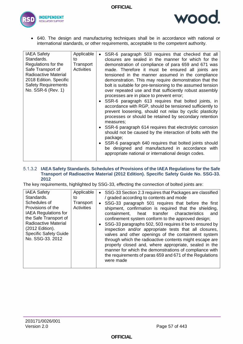
OFFICIAL
203171/0026/001 Version 2.0
Page 57 of 443
OFFICIAL
640. The design and manufacturing techniques shall be in accordance with national or international standards, or other requirements, acceptable to the competent authority.
IAEA Safety Standards. Regulations for the Safe Transport of Radioactive Material 2018 Edition. Specific Safety Requirements No. SSR-6 (Rev. 1)
Applicable to Transport Activities
SSR-6 paragraph 503 requires that checked that all closures are sealed in the manner for which for the demonstration of compliance of para 659 and 671 was made. Therefore it must be ensured all joints are tensioned in the manner assumed in the compliance demonstration. This may require demonstration that the bolt is suitable for pre-tensioning to the assumed tension over repeated use and that sufficiently robust assembly processes are in place to prevent error;
SSR-6 paragraph 613 requires that bolted joints, in accordance with RGP, should be tensioned sufficiently to prevent loosening, should not relax by cyclic plasticity processes or should be retained by secondary retention measures;
SSR-6 paragraph 614 requires that electrolytic corrosion should not be caused by the interaction of bolts with the package;
SSR-6 paragraph 640 requires that bolted joints should be designed and manufactured in accordance with appropriate national or international design codes.
IAEA Safety Standards. Schedules of Provisions of the IAEA Regulations for the Safe Transport of Radioactive Material (2012 Edition). Specific Safety Guide No. SSG-33. 2012
The key requirements, highlighted by SSG-33, effecting the connection of bolted joints are:
IAEA Safety Standards. Schedules of Provisions of the IAEA Regulations for the Safe Transport of Radioactive Material (2012 Edition). Specific Safety Guide No. SSG-33. 2012
Applicable to Transport Activities
SSG-33 Section 2.3 requires that Packages are classified / graded according to contents and mode
SSG-33 paragraph 501 requires that before the first shipment, confirmation is required that the shielding, containment, heat transfer characteristics and confinement system conform to the approved design;
SSG-33 paragraphs 502, 503 requires it be to ensured by inspection and/or appropriate tests that all closures, valves and other openings of the containment system through which the radioactive contents might escape are properly closed and, where appropriate, sealed in the manner for which the demonstrations of compliance with the requirements of paras 659 and 671 of the Regulations were made
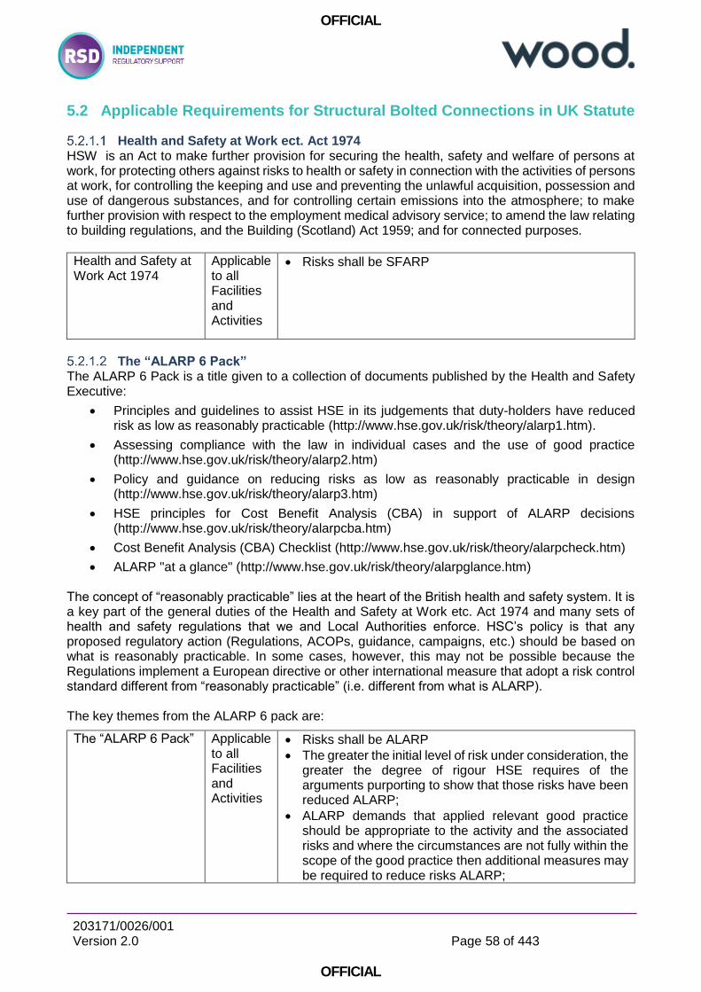
OFFICIAL
203171/0026/001 Version 2.0
Page 58 of 443
OFFICIAL
5.2 Applicable Requirements for Structural Bolted Connections in UK Statute
Health and Safety at Work ect. Act 1974 HSW is an Act to make further provision for securing the health, safety and welfare of persons at work, for protecting others against risks to health or safety in connection with the activities of persons at work, for controlling the keeping and use and preventing the unlawful acquisition, possession and use of dangerous substances, and for controlling certain emissions into the atmosphere; to make further provision with respect to the employment medical advisory service; to amend the law relating to building regulations, and the Building (Scotland) Act 1959; and for connected purposes.
Health and Safety at Work Act 1974
Applicable to all Facilities and Activities
Risks shall be SFARP
The “ALARP 6 Pack” The ALARP 6 Pack is a title given to a collection of documents published by the Health and Safety Executive:
Principles and guidelines to assist HSE in its judgements that duty-holders have reduced risk as low as reasonably practicable (http://www.hse.gov.uk/risk/theory/alarp1.htm).
Assessing compliance with the law in individual cases and the use of good practice (http://www.hse.gov.uk/risk/theory/alarp2.htm)
Policy and guidance on reducing risks as low as reasonably practicable in design (http://www.hse.gov.uk/risk/theory/alarp3.htm)
HSE principles for Cost Benefit Analysis (CBA) in support of ALARP decisions (http://www.hse.gov.uk/risk/theory/alarpcba.htm)
Cost Benefit Analysis (CBA) Checklist (http://www.hse.gov.uk/risk/theory/alarpcheck.htm)
ALARP "at a glance" (http://www.hse.gov.uk/risk/theory/alarpglance.htm) The concept of “reasonably practicable” lies at the heart of the British health and safety system. It is a key part of the general duties of the Health and Safety at Work etc. Act 1974 and many sets of health and safety regulations that we and Local Authorities enforce. HSC’s policy is that any proposed regulatory action (Regulations, ACOPs, guidance, campaigns, etc.) should be based on what is reasonably practicable. In some cases, however, this may not be possible because the Regulations implement a European directive or other international measure that adopt a risk control standard different from “reasonably practicable” (i.e. different from what is ALARP). The key themes from the ALARP 6 pack are:
The “ALARP 6 Pack” Applicable to all Facilities and Activities
Risks shall be ALARP
The greater the initial level of risk under consideration, the greater the degree of rigour HSE requires of the arguments purporting to show that those risks have been reduced ALARP;
ALARP demands that applied relevant good practice should be appropriate to the activity and the associated risks and where the circumstances are not fully within the scope of the good practice then additional measures may be required to reduce risks ALARP;
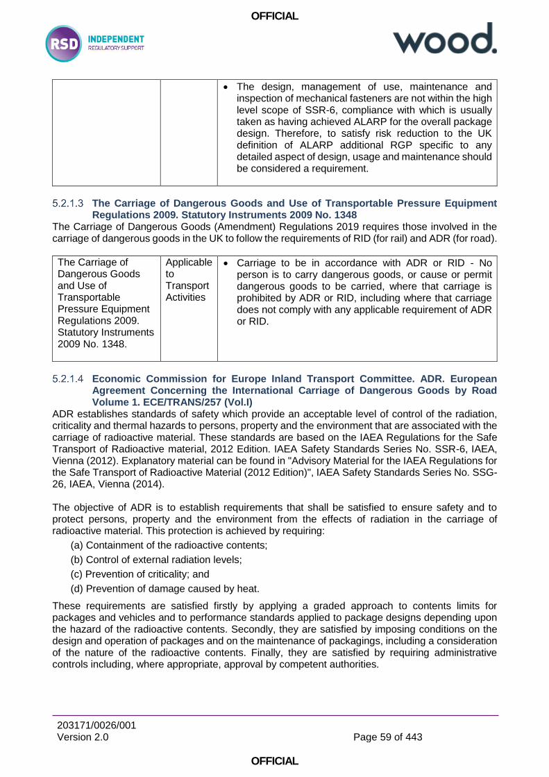
OFFICIAL
203171/0026/001 Version 2.0
Page 59 of 443
OFFICIAL
The design, management of use, maintenance and inspection of mechanical fasteners are not within the high level scope of SSR-6, compliance with which is usually taken as having achieved ALARP for the overall package design. Therefore, to satisfy risk reduction to the UK definition of ALARP additional RGP specific to any detailed aspect of design, usage and maintenance should be considered a requirement.
The Carriage of Dangerous Goods and Use of Transportable Pressure Equipment Regulations 2009. Statutory Instruments 2009 No. 1348
The Carriage of Dangerous Goods (Amendment) Regulations 2019 requires those involved in the carriage of dangerous goods in the UK to follow the requirements of RID (for rail) and ADR (for road).
The Carriage of Dangerous Goods and Use of Transportable Pressure Equipment Regulations 2009. Statutory Instruments 2009 No. 1348.
Applicable to Transport Activities
Carriage to be in accordance with ADR or RID - No person is to carry dangerous goods, or cause or permit dangerous goods to be carried, where that carriage is prohibited by ADR or RID, including where that carriage does not comply with any applicable requirement of ADR or RID.
Economic Commission for Europe Inland Transport Committee. ADR. European Agreement Concerning the International Carriage of Dangerous Goods by Road Volume 1. ECE/TRANS/257 (Vol.I)
ADR establishes standards of safety which provide an acceptable level of control of the radiation, criticality and thermal hazards to persons, property and the environment that are associated with the carriage of radioactive material. These standards are based on the IAEA Regulations for the Safe Transport of Radioactive material, 2012 Edition. IAEA Safety Standards Series No. SSR-6, IAEA, Vienna (2012). Explanatory material can be found in "Advisory Material for the IAEA Regulations for the Safe Transport of Radioactive Material (2012 Edition)", IAEA Safety Standards Series No. SSG-26, IAEA, Vienna (2014). The objective of ADR is to establish requirements that shall be satisfied to ensure safety and to protect persons, property and the environment from the effects of radiation in the carriage of radioactive material. This protection is achieved by requiring:
(a) Containment of the radioactive contents;
(b) Control of external radiation levels;
(c) Prevention of criticality; and
(d) Prevention of damage caused by heat.
These requirements are satisfied firstly by applying a graded approach to contents limits for packages and vehicles and to performance standards applied to package designs depending upon the hazard of the radioactive contents. Secondly, they are satisfied by imposing conditions on the design and operation of packages and on the maintenance of packagings, including a consideration of the nature of the radioactive contents. Finally, they are satisfied by requiring administrative controls including, where appropriate, approval by competent authorities.
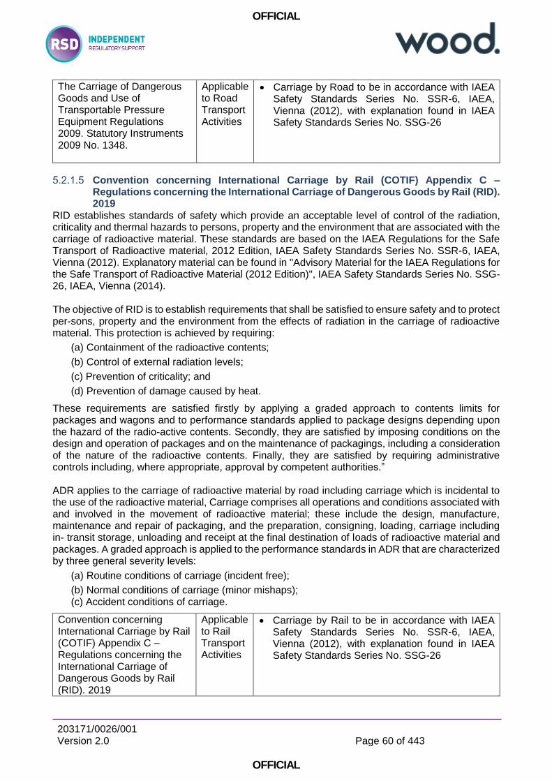
OFFICIAL
203171/0026/001 Version 2.0
Page 60 of 443
OFFICIAL
The Carriage of Dangerous Goods and Use of Transportable Pressure Equipment Regulations 2009. Statutory Instruments 2009 No. 1348.
Applicable to Road Transport Activities
Carriage by Road to be in accordance with IAEA Safety Standards Series No. SSR-6, IAEA, Vienna (2012), with explanation found in IAEA Safety Standards Series No. SSG-26
Convention concerning International Carriage by Rail (COTIF) Appendix C – Regulations concerning the International Carriage of Dangerous Goods by Rail (RID). 2019
RID establishes standards of safety which provide an acceptable level of control of the radiation, criticality and thermal hazards to persons, property and the environment that are associated with the carriage of radioactive material. These standards are based on the IAEA Regulations for the Safe Transport of Radioactive material, 2012 Edition, IAEA Safety Standards Series No. SSR-6, IAEA, Vienna (2012). Explanatory material can be found in "Advisory Material for the IAEA Regulations for the Safe Transport of Radioactive Material (2012 Edition)", IAEA Safety Standards Series No. SSG-26, IAEA, Vienna (2014). The objective of RID is to establish requirements that shall be satisfied to ensure safety and to protect per-sons, property and the environment from the effects of radiation in the carriage of radioactive material. This protection is achieved by requiring:
(a) Containment of the radioactive contents;
(b) Control of external radiation levels;
(c) Prevention of criticality; and
(d) Prevention of damage caused by heat.
These requirements are satisfied firstly by applying a graded approach to contents limits for packages and wagons and to performance standards applied to package designs depending upon the hazard of the radio-active contents. Secondly, they are satisfied by imposing conditions on the design and operation of packages and on the maintenance of packagings, including a consideration of the nature of the radioactive contents. Finally, they are satisfied by requiring administrative controls including, where appropriate, approval by competent authorities.” ADR applies to the carriage of radioactive material by road including carriage which is incidental to the use of the radioactive material, Carriage comprises all operations and conditions associated with and involved in the movement of radioactive material; these include the design, manufacture, maintenance and repair of packaging, and the preparation, consigning, loading, carriage including in transit storage, unloading and receipt at the final destination of loads of radioactive material and packages. A graded approach is applied to the performance standards in ADR that are characterized by three general severity levels:
(a) Routine conditions of carriage (incident free);
(b) Normal conditions of carriage (minor mishaps); (c) Accident conditions of carriage.
Convention concerning International Carriage by Rail (COTIF) Appendix C – Regulations concerning the International Carriage of Dangerous Goods by Rail (RID). 2019
Applicable to Rail Transport Activities
Carriage by Rail to be in accordance with IAEA Safety Standards Series No. SSR-6, IAEA, Vienna (2012), with explanation found in IAEA Safety Standards Series No. SSG-26

OFFICIAL
203171/0026/001 Version 2.0
Page 61 of 443
OFFICIAL
5.3 Applicable Requirements for Structural Bolted Connections in ONR Guidance
The safety of nuclear installations in Great Britain (GB) is assured by a system of regulatory control based on a licensing process by which a corporate body is granted a licence to use a defined site for specified activities. Any facility or activity occurring on a Licensed Site shall satisfy License Conditions (LCs) and it is incumbent on the Licensee to satisfy LCs for all facilities and activities, including those which may be used for transport activities off-site. Safety Assessment Principles (Ref D2) guide inspectors in their regulatory judgements on the safety of activities and designers and duty-holders in defining regulatory expectations. Further detailed guides provide assistance in various specialised areas. Generally there is no ONR guidance specific to the good performance of bolted joints and mechanical fasteners which have an important contribution to safety. The high level advice for structural integrity is broadly applicable to bolted joint SSCs.
5.3.1 ONR Guidance Applicable to All SSCs Important to Safety
ONR. License condition handbook. February 2017 A number of ONR License Conditions may be used to regulate the design, assembly, inspection, maintenance and use of bolted connections on site. ONR NS-TAST-GD-016 Revision 5 provides a comprehensive review of License Conditions which may apply generically to any matter of structural integrity, which in turn will generally apply also to mechanical fasteners important to safety. Throughout the LCs (particularly LC14, LC 23 and LC 28) Licensing is dependent on the requirement to maintain the approved configuration and state of design, including joints through control of design, safety justifications, usage and maintenance. Allowing deviation from the approved configuration would be deemed a breach of a number of LCs. In support of LC 34 it is incumbent on the Licensee to ensure that containment devices are sealed in the manner assumed in the safety justification.
ONR. License condition handbook. February 2017
Applicable to all Facilities
Licence Condition 14 - Safety documentation (the licensee shall make and implement adequate arrangements for the production and assessment of safety cases consisting of documentation to justify safety during the design, construction, manufacture, commissioning, operation and decommissioning phases of the installation).
The licensee shall ensure that once approved no alteration or amendment is made to the approved arrangements unless ONR has approved such alteration or amendment. The Licensee shall therefore ensure that fasteners which make an important contribution to safety are as specified and assembled as specified as stated in any safety justifications.
The licensee shall make and implement adequate arrangements for the regular and systematic examination, inspection, maintenance and testing of all plant which may affect safety.
OFFICIAL
203171/0026/001 Version 2.0
Page 62 of 443
OFFICIAL
ONR. Safety Assessment Principles for Nuclear Facilities. 2014 Edition Revision 0 There are no SAPs which specifically apply to the integrity of bolted joints, although a number which may apply generically to any aspect of structural integrity. Reference D5 “ONR Guide. Integrity of Metal Structures, Systems and Components. Nuclear Safety Technical Assessment Guide NS-TAST-GD-016 Revision 5. March 2017”, which highlights key SAPs clauses pertinent to all matters of structural integrity, of which bolted joints are a subset Adoption of detailed and specific RGP relevant to the function of any Structure, System or Component, or any part of an SSC which performs a specific function is key to assuring good performance of mechanical fasteners however. Attention is therefore drawn to those relating to Engineering Principles: safety classification and standards (“The safety functions to be delivered within the facility, both during normal operation and in the event of a fault or accident, should be identified and then categorised based on their significance with regard to safety”: ECS.3 is pertinent to “Codes and Standards” and states that “Structures, systems and components that are important to safety should be designed, manufactured, constructed, installed, commissioned, quality assured, maintained, tested and inspected to the appropriate codes and standards”.
Clauses 169 to 173 provide further interpretation of the above:
- (169) The codes and standards applied should reflect the functional reliability requirements of the structures, systems and components and be commensurate with their safety classification.
- (170) Codes and standards should be preferably nuclear-specific, leading to a conservative design commensurate with the importance of the safety function(s) being delivered. Each code or standard adopted should be evaluated to determine its applicability, adequacy and sufficiency and should be supplemented or modified as necessary to a level commensurate with the importance of the relevant safety function(s).
- (171) Appropriate nuclear industry-specific, national or international codes and standards should be adopted for Class 1 and 2 structures, systems or components. For Class 3, if there is no appropriate nuclear industry-specific code or standard, an appropriate non-nuclear-specific code or standard should be applied instead.
- (172) Where a single item (ie a structure, system or component) needs to deliver multiple safety functions, and these can be demonstrated to be delivered by the item independently of one another, then separate codes and standards should be used appropriate to the parts of the item providing each safety function. Where such independence cannot be demonstrated, codes and standards should be appropriate to the class of the item (ie in accordance with the highest category of safety function to be delivered). Whenever different codes and standards are used for different aspects of the same item, the compatibility between these codes and standards should be demonstrated.
- (173) The combining of different codes and standards for a single aspect of a structure, system or component should be avoided. Where this cannot be avoided, the combining of the codes and standards should be justified and their mutual compatibility demonstrated.
ECS.4 is pertinent to the “Absence of established codes and standards” and states “Where there are no appropriate established codes or standards, an approach derived from existing codes or standards for similar equipment, in applications with similar safety significance, should be adopted”.
ECS.5 is pertinent to the “Use of experience, tests or analysis” and states that “In the absence of applicable or relevant codes and standards, the results of experience, tests, analysis, or a combination thereof, should be applied to demonstrate that the structure, system or component will perform its safety function(s) to a level commensurate with its classification.”
OFFICIAL
203171/0026/001 Version 2.0
Page 63 of 443
OFFICIAL
There is no specific advice for the integrity of bolted joints and this may be an omission under the EMC SAPs. In light of the statement (see Ref E1 “IAEA. Assessment and Management of Ageing of Major Nuclear Power Plant Components Important to Safety: PWR Pressure Vessels 2007 Update. IAEA-TECDOC-1556” that the most susceptible components to fatigue are closure bolts, and the inclusion of some specific advice for welds in EMC.10 (relating to weld positions), then bolted joints which are critical to safety warrant some specific advice.
ONR. Safety Assessment Principles for Nuclear Facilities. 2014 Edition Revision 0.
Applicable to all Facilities and Activities
All SSCs (including Mechanical Fasteners) that are important to safety should be designed, manufactured, constructed, installed, commissioned, quality assured, maintained, tested and inspected to the appropriate codes and standards.
(169) The codes and standards applied should reflect the functional reliability requirements of the structures, systems and components and be commensurate with their safety classification.
(172) Where a single item (ie a structure, system or component) needs to deliver multiple safety functions, and these can be demonstrated to be delivered by the item independently of one another, then separate codes and standards should be used appropriate to the parts of the item providing each safety function.
ONR Guide. Guidance on the Demonstration of ALARP (As Low As Reasonably Practicable). Nuclear Safety Technical Assessment Guide NS-TAST-GD-005 Revision 9. March 2018.
The requirement for risks to be ALARP is fundamental and applies to all activities within the scope of the Health and Safety at Work (etc) Act 1974 [HSWA]. It is important that inspectors in whatever role are aware of the need to ensure that licensees meet this requirement where it applies. In simple terms it is a requirement to take all measures to reduce risk where doing so is reasonable. In most cases this is not done through an explicit comparison of costs and benefits, but rather by applying established relevant good practice and standards.
ONR. Safety Assessment Principles for Nuclear Facilities. 2014 Edition Revision 0
Applicable to all Facilities and Activities
It is a requirement to take all measures to reduce risk where doing so is reasonable. In most cases this is not done through an explicit comparison of costs and benefits, but rather by applying established relevant good practice and standards.
ONR Guide. Examination, Inspection, Maintenance and Testing of Items Important to Safety. Nuclear Safety Technical Assessment Guide NS-TAST-GD-009 Revision 5. May 2019.
Reference D4 directly addresses those ONR SAPs [Ref 1] which relate to in-service and throughout facility life EIMT; EMT.1 to EMT.8 in support of LC 28.
ONR Guide. Integrity of Metal Structures, Systems and Components. Nuclear Safety Technical Assessment Guide NS-TAST-GD-016 Revision 5. March 2017
Reference D5 provides ONR inspectors with additional guidance and interpretation of SAPs EMC.1 to EMC.34 which are concerned with the integrity of metal structures, systems and components (SSCs). The majority of SAPS applicable to structural integrity apply to bolted joints also.
OFFICIAL
203171/0026/001 Version 2.0
Page 64 of 443
OFFICIAL
There is no specific advice for the integrity of bolted joints and this may be a consequence of there being no SAPs specific to the design , engineering, installation, maintenance and testing of bolted joints which have an important contribution to safety. Given the importance, susceptibility to fatigue and the most onerous inspection requirements then some specific focus would be appropriate. The primary licence conditions (LCs) for which assessments of metal SSCs are to be carried out are:
• LC 14 (Safety documentation) • LC 15 (Periodic review) • LC 17 (Management systems) • LC 19 (Construction or installation of new plant) • LC 20 (Modification to design of plant under construction) • LC 21 (Commissioning) • LC 22 (Modification or experiment on existing plant) • LC 23 (Operating rules) • LC 24 (Operating instructions) • LC 25 (Operational records) • LC 26 (Control and supervision of operations) • LC 27 (Safety mechanisms, devices and circuits) • LC 28 (Examination, inspection, maintenance and testing) • LC 29 (Duty to carry out tests, inspections and examinations) • LC 30 (Periodic shutdown) • LC 34 (Leakage and escape of radioactive material and radioactive waste) • LC 35 (Decommissioning)
The SAPs relating to the integrity of metal SSCs are:
Highest reliability structures or components:
EMC.1 (Safety case and assessment)
EMC.2 (Use of scientific and technical issues)
EMC.3 (Evidence)
General
EMC.4 (Procedural control)
EMC.5 (Freedom from and tolerance of defects)
EMC.6 (Means to identify defects)
Design
EMC.7 (Loadings)
EMC.8 (Providing for examination)
EMC.9 (Product form)
EMC.10 (Weld positions)
EMC.11 (Failure modes)
EMC.12 (Brittle behaviour)
Manufacture and installation
EMC.13 (Materials)
EMC.14 (Techniques and procedures)
EMC.15 (Control of materials)
EMC.16 (Contamination)
EMC.18 (Third-party inspection)
EMC.19 (Non-conformances)
EMC.20 (records)
Manufacturing, pre-service and in-service examination and testing
OFFICIAL
203171/0026/001 Version 2.0
Page 65 of 443
OFFICIAL
EMC.27 (Examination)
EMC.28 (Margins)
EMC.29 (Redundancy and diversity)
EMC.30 (Qualification)
Operation
EMC.21 (Safe operating envelope)
EMC.22 (Material compatibility)
EMC.23 (Ductile behaviour)
Monitoring
EMC.24 (Operation)
EMC.25 (Leakage)
EMC.26 (Forewarning of failure)
In-service repairs and modifications
EMC.31 (Repairs and modifications)
Analysis
EMC.32 (Stress analysis)
EMC.33 (Use of data)
EMC.34 (Defect sizes)
Ageing and degradation
EAD.1 (Safe working life)
EAD.2 (Lifetime margins)
EAD.3 (Periodic measurement of material properties)
EAD.4 (Periodic measurement of parameters)
EAD.5 (Obsolescence)
ONR Guide. The Purpose, Scope and Content of Safety Cases. Nuclear Safety Technical Assessment Guide NS-TAST-GD-051 Revision 4. June 16
NS-TAST-GD-051 Revision 4 supports the interpretation of the ONT SAPs and states that “Fundamental to the safety case are the principles, standards and criteria which the licensee intends to maintain. These must, as a minimum, meet statutory requirements and in particular, show that risks to individuals will be acceptably low and ALARP” It is a key requirement of UK ALARP to adopt RGP wherever appropriate (which would include the design and execution of bolted joints) and NS-TAST-GD-051 Revision 4 highlights the requirement for all safety cases to “demonstrate that the facility conforms to relevant good engineering practice and sound safety principles. (For example, a nuclear facility should be designed against a set of deterministic engineering rules, such as design codes and standards, using the concept of ‘defence in depth’1 and with adequate safety margins.)”
ONR Guide. The Purpose, Scope and Content of Safety Cases. Nuclear Safety Technical Assessment Guide NS-TAST-GD-051 Revision 4. June 16
Applicable to all Facilities and Activities
The term ‘nuclear safety case’ may relate to a site, a facility, part of a facility, a modification to a facility or to the operations within a facility, or to one or more significant issues.
A safety case should demonstrate that the facility conforms to relevant good engineering practice and sound safety principles. (For example, a nuclear facility should be designed against a set of deterministic engineering rules, such as design codes and standards, using the concept of ‘defence in depth’1 and with adequate safety margins.)
OFFICIAL
203171/0026/001 Version 2.0
Page 66 of 443
OFFICIAL
Fundamental to the safety case are the principles, standards and criteria which the licensee intends to maintain. These must, as a minimum, meet statutory requirements and in particular, show that risks to individuals will be acceptably low and ALARP. They will include design standards, safety criteria and general standards of safety management. They should be mutually consistent and their selective use should be avoided.
5.3.2 ONR Guidance Applicable to Nuclear Pressure Retaining SSCs Important to Safety
ONR Guide. Categorisation of Safety Functions and Classification of Structures, Systems and Components. Nuclear Safety Technical Assessment Guide NS-TAST-GD-094 Revision 0. November 2015
Safety function categorisation is the process by which safety functions are categorised based on their significance with regard to safety, (see SAP ECS.1 at paragraph 5.2.3.1). SSC classification is the process by which SSCs are classified on the basis of their significance in delivering associated safety functions, (see SAP ECS.2). The classification assigned to a SSC indicates the level of confidence required for it to deliver its safety function. It should be used to determine the standards and relevant good practice (RGP) to which SSCs are designed, manufactured, constructed, installed, commissioned, quality assured, maintained, tested and inspected, (see SAP ECS.3).
5.3.3 ONR Guidance Applicable to Transport Packages
ONR Guide. Transport Engineering Assessment . Nuclear Safety Technical Assessment Guide NS-TAST-GD-099 Revision 0. April 2017
NS-TAST-GD-099 Revision 0 is closely aligns the package approval to compliance with IAEA SSR-6. SSR-6 broadly considers only requirements (e.g. loads and conditions) associated to the actual transport of packages and is focussed on Nuclear Safety and containment. CDG, ADR, RID and SSR-6 does not consider potentially more stringent requirements of UK ALARP, which legally mandate the adoption of RGP the adoption of all relevant RGP, for activities conducted on a Licensed Site. It is a concern that such requirements may be design bounding and ultimately necessary for Shipment Approvals. Application Part 1 should “contain general and administrative information, including a requirement to provide details of the relevant management system(s) covering all aspects of design, manufacture and use, showing that these arrangements will ensure that the requirements of the safety case will be adequately implemented” Where the performance of SSCs, such as fasteners, is variable or subject to human error, then this variability should be accounted for in the management arrangements. Noting that Package Design Approval can be considered based solely on SSR-6 compliance and ahead of site and transport safety cases, RSD consider NS-TAST-GD-099 Revision 0 could be revised to clearly state that any design bounding requirements for safe site operations and practices (such as lifting or other UK specific ALARP considerations) should not be ignored in the package design and approval process. In particular, UK ALARP (see “ALARP 6-Pack”) may take precedence and necessitate the implementation of more detailed RGP and management arrangements in relation to the design and execution of specific design features, such as bolted joints.

OFFICIAL
203171/0026/001 Version 2.0
Page 67 of 443
OFFICIAL
ONR Guide. GUIDANCE FOR APPLICATIONS FOR UK COMPETENT AUTHORITY APPROVAL (ONR Transport Permissioning - External Guidance) TRA-PER-GD-014 Revision 1. July 2016
TRA-PER-GD-014 Revision 1 is a guide for applicants defining regulatory expectations for the content of applications to the Competent Authority for transport of Radioactive Material. The highest level expectations are that “Part 1 should explain why the design and its operation are safe. It should summarise and make reference to the detailed evidence in Part 2 that substantiates the claims made in Part 1.” Part 2 for the applications should demonstrate that “the components of the design will meet their safety performance requirements and provide the necessary safety functions during routine, normal and accident conditions of transport, as defined in the regulations.” RSD note that the regulations (SSR-6) provide the minimum standard safety baseline to allow transfrontier transportation between multiple regulatory domains. The ultimate proof of safety may require consideration of local practices, such as assembly methods and handling, as well as any more stringent safety requirements.
ONR Guide. General Guidance for Mechanical Engineering Specialism Group. Nuclear Safety Technical Assessment Guide NS-TAST-GD-102 Revision 0. January 2019
NS-TAST-GD-102 Revision 0 Appendix A is an ONR guide for “Quality Assured Bolting in Safety Critical Applications”. Mechanical Engineering inspection activities have issued challenge regarding the use of fasteners within safety critical structures, systems and components (SSCs) e.g. load-path components or structural fastenings, and whether there was evidence of the quality assurance (QA) documentation available for review. Previous inspections have shown that robust QA evidence of fasteners meeting their design requirements is inconsistent. A lack of QA evidence leads to further questions regarding claimed reliability of safety critical SSCs. This guidance sets regulatory expectations for such applications. This provides a set of high-level requirements concerning quality assurance measures that should be in place as part of good practice in quality management procedures of safety critical SSCs. Guidance on how examination, inspection, maintenance, and testing (EIMT) should be used to ensure the integrity of mechanical joints throughout the lifetime of the plant is also identified (see Section A1.2.4). NS-TAST-GD-102 Section A1.2.4 (In-service inspection) states that fasteners should be inspected for:
• signs of gapping or “nicks” in threads and equally, checks to determine if bolts have yielded;
• where safety critical bolts are used in structural applications, a suitable methodology for in-service inspection or planned replacement strategy should be provided by the licensee; and
Noting, that for pre-loaded fasteners, it is fundamental objective of tightening to tension the bolt to, beyond its yield stress, then it is concluded that fasteners should not be re-used wherever replaceable. Conversely, fasteners which are non-preloaded or pre-loaded below code requirements, may be re-used should inspection prove satisfactory.
OFFICIAL
203171/0026/001 Version 2.0
Page 68 of 443
OFFICIAL
5.4 Applicable IAEA Relevant Good Practice for Structural Bolted Connection in Nuclear Plant
5.4.1 IAEA RGP for Pressurised Water Reactors
IAEA. Assessment and Management of Ageing of Major Nuclear Power Plant Components Important to Safety: PWR Pressure Vessels 2007 Update. IAEA-TECDOC-1556.
Reference E1 reviews global practice for Assessment and Management of components comprising PWR RPVs worldwide, with a focus on head bolts due to their fatigue vulnerability. Assessment and management is broken into the following filtered sections and topics which may relate to Closure Head Studs:
Design features and materials of worldwide PWR RPVs o Typically SA320 L43
Codes and guides used for assessment o Design basis typically to ASME Section HI o Analysis of Normal, Upset, Emergency, Faulted and Testing conditions typically following
ASME III or related international BPVC codes o Analysis of Fatigue o Analysis of Brittle Fracture
Ageing mechanisms o Fatigue (important to Closure Head Studs) o Crack propagation typically to ASME Section XI o Boric acid corrosion (root cause of a small number of failures)
Inspection and monitoring requirements o Inspection in accordance with Section XI of the ASME Code
Preservice First in-service Subsequent in-service interval inspections All studs and threaded stud holes in the closure head need surface and volumetric
examinations at each inspection interval in USA, sampling elsewhere with 100% within 10 years
UT, visual and Eddy-Current
o Material surveillance programmes, loose-parts (noise) monitoring during operation, leak detection during operation, and fatigue monitoring systems generally deployed
Ageing assessment methods o Fatigue reanalysis o Crack propagation / flaw assessment reanalysis o Boric acid corrosion assessment
Ageing mitigation methods / Ageing management programmes o operation within operating guidelines aimed at minimizing the rate of degradation -
managing ageing mechanisms (Sections 8.1.3 and 7); o inspection and monitoring consistent with requirements aimed at timely detection and
characterization of any degradation (Section 5); o assessment of the observed degradation in accordance with appropriate guidelines to
determine integrity (Section 6); and o maintenance (repair or parts replacement) to correct unacceptable degradation -
managing ageing effects (Section 7)
OFFICIAL
203171/0026/001 Version 2.0
Page 69 of 443
OFFICIAL
Studs are generally from similar material to the RPV forgings and are very similar in principle worldwide. It is noted that RPV closure studs have the highest fatigue usage factor of any the RPV subcomponents, however the processes of assessment and management of RPV head studs are well established in the worldwide civil nuclear industry and there is little benefit in reproducing the process here. Good practice is described in detail in IAEA-TECDOC-1556 (or Section 6.5 of this report) and direct reference is recommended for explanation of the key processes to ensure safety.
5.4.2 IAEA RGP for Boiling Water Reactors
IAEA. Assessment and management of ageing of major nuclear power plant components important to safety: BWR pressure vessels. IAEA-TECDOC-1470
High level guidance for design assurance, assessment of degradation mechanisms and management of ageing mechanisms is as per PWRs in Section 5.4.1.1.
5.5 Current Guidance in the Assessment and Management of Transport Packages (UK)
Current UK Guidance is guided locally by the Transport Container Safety Committee (TCSC) and whilst any other RGP suitable to support compliance to the Requirements is permitted, TCSC documents reflect closely current typical practice in the UK in Applications for Design and Transport Certificates.
5.5.1 TCSC 1006 Transport of Radioactive Material Code of Practice - Guide to the Securing/Retention of Radioactive Material Payloads and Packages During Transport. July 2018
TCSC provides guidance only for the lifting, tie-down and retention systems of Packages based on IAEA SSG-26, and recommends high level design codes (BS 2573 part 1 and EN 13001) appropriate to assure the structural integrity of components comprising the retention systems. The codes are normally used for lifting applications. However, RSD observe that the practices recommended in TCSC 1006 are frequently extended to the entirety of Transport Package Design. It should be noted that there is no recommendation for these codes to be used for any other aspect of the design or other components or elements of Packages that fulfil other functions. ONR SAP ECS.3 states that “(172) Where a single item (ie a structure, system or component) needs to deliver multiple safety functions, and these can be demonstrated to be delivered by the item independently of one another, then separate codes and standards should be used appropriate to the parts of the item providing each safety function. Where such independence cannot be demonstrated, codes and standards should be appropriate to the class of the item (ie in accordance with the highest category of safety function to be delivered). Whenever different codes and standards are used for different aspects of the same item, the compatibility between these codes and standards should be demonstrated.” RSD note that there no parts BS EN 13001 still to be published that would prevent its application to assuring the integrity of elements of transport packages important to the safety of lifting operations. It is noted that the code is considerably more comprehensive than BS 2573 Part 1 that it supersedes, particularly in the guidance pertinent to good function of bolted joints and mechanical fasteners. Pertinence to function and compatibility then naturally dictates the adoption of other appropriate Euro Norms for the integrity, materials selection, quality, maintenance and management processes for the verification of the remainder of the package TCSC 1006 provides loads which may be used for the proof of Tie-Down systems for:
OFFICIAL
203171/0026/001 Version 2.0
Page 70 of 443
OFFICIAL
Routine Conditions of Transport (RCT), representing typical transport loadings;
Normal Conditions of Transport (NCT), representing abnormal transport loadings;
Fatigue. TCSC 1006 recommends guidance for fatigue be taken from BS EN 1993-1-9 or BS 7608:2014.
5.5.2 TCSC 1086 Transport of Radioactive Material Code of Practice - Good Practice Guide to Drop Testing of Type B Transport Package
TCSC 1086 concentrates on good practice in planning, executing and analysing drop tests. TCSC 1086 highlights the role of bolt pre-stress in the impact performance and sealing of Transport Packages subjected to the test conditions required by SSR-6. Bolt pre-stress (and the applicant should note this may not automatically be reflected by applied torque) should correspond the level in the actual packages. Any change in prevailing torque in the fasteners as a result of the tests should be measured, recorded and reported.
5.5.3 TCSC 1087 Transport of Radioactive Material Code of Practice - The Application of Finite Element Analysis to Demonstrate Impact Performance of Transport Package Design March 2018
The Finite Element Method (FEM) is a powerful tool for the simulation of structural and thermal behaviour of structures. In recent years, the explicit FEM has increasingly been used in the development of transport packages and as part of approval applications to demonstrate the performance of packages. This Guide sets out current ‘good practice’ in using the explicit FEM for the analysis of impact behaviour of transport packages and specifically for the demonstration of compliance with the UK regulations for public domain transport when applying for the necessary approval from the UK Office for Nuclear Regulation. The objective is to raise the standard of Finite Element (FE) analyses so as to improve the confidence that can be placed in FE analyses to enable them to take a more central role in demonstrating regulatory compliance. In relation or relevance to the correct modelling of bolted joints TCSC 1087 recommends:
Element types to be used - Bolts can be modelled as simple beams or where greater accuracy is required, with solid elements
Pre-loading - Bolt pre-stress could have a significant effect on the behaviour of the bolted connection and it should be modelled, unless not modelling it could be justified
Careful selection of material model - Where they are available, realistic stress strain curves should be used for all components, and especially for components that undergo large deformations.
Acceptance criteria.
5.5.4 TCSC 31 Transport of Radioactive Material Code of Practice - Design and Operation to Minimise Seizure of Fasteners. June 2014
RSD observe that TCSC 31 is not frequently referenced in Transport Package Applications.
OFFICIAL
203171/0026/001 Version 2.0
Page 71 of 443
OFFICIAL
TCSC 31 contains guidance to reduce the likelihood of galling through design, operational and management practices. Seizure or surface damage of threads can arise when assembling or dismantling screw threaded components. One of the most severe forms that can occur is termed ‘galling’, where gross damage of the thread surfaces and in some cases total seizure can occur. The problem of thread seizure is most commonly caused by one or more of the following conditions:
(a) Use of certain materials which are prone to seizing, e.g. austenitic stainless steels, pure aluminium, copper.
(b) Insufficient clearance between the mating screw threads.
(c) Poor surface finish.
(d) Inaccurate thread form.
(e) Workshop residues on the threads.
(f) Damage or burrs to the threads.
(g) Inaccurate alignment of the mating threads – particularly when the thread diameter is large in relation to the thread pitch.
In addition, surface hardness, cleanliness, lubrication and the choice of thread can all effect the interaction between the metal surfaces that make up the mating threads. TCSC makes a number of recommendations, which are summarised (at a high level) as follows:
Materials Dissimilar bolting materials can reduce galling tendency, but this can promote corrosion.
Surface Finish Surface roughness Ra should be between 0.4μm and 3μm.
Surface Treatment Surface treatment by heat treatment, Ion Implantation or plating is recommended, with caution against electroplating of Grade 12.9 due to the risk or hydrogen embrittlement.
Cleaning Threaded components should be cleaned and stored in such a way to prevent contamination
Lubrication Dry lubricants such as molybdenum disulphide are generally most desirable. For stainless steels anti-scuffing compounds may suit the application, but care must be taken to select a compatible lubricant for a nuclear application.
Inspection Threads should be inspected using Screw Ring Gauges
Tightening Torque Bolts should be tightened to result in an acceptable pre-load, typically 70-80% of yield stress as recommended by BS 2573 Part 1. Tightening torque may be calculated from T = 1/5 Po D (where T = Tightening torque, Po = Preload, D = Basic major diameter) as per BS 3580. However, friction coefficients can vary greatly, particularly in stainless steels and the torque-tension relationship should be determined experimentally in critical applications.
Stainless steel components Thread clearance should be increased.
Mixing martensitic and austenitic may reduce galling.

OFFICIAL
203171/0026/001 Version 2.0
Page 72 of 443
OFFICIAL
Operations It would be useful to measure de-torque values.
5.6 Summary of Relevant UK and International Nuclear Applicable Relevant Good Practice for the design and execution of bolted connections
5.6.1 Boiler Pressure Code Applicable to RPVs and other pressure retaining Nuclear Plant
Nuclear Plant is typically designed, constructed, inspected and monitored to ASME Boiler pressure Vessel codes (or other international derived equivalents). For brevity a high level summary or relevant requirements applicable to bolted joints is presented here. ASME BPVC.III.NCA-2019 provides high level general requirements applicable to:
a) Division 1 specifying rules for 1) nuclear power system metal components, parts, and appurtenances 2) metal containment vessels 3) supports
b) Division 2 specifies rules for concrete containments Relevant Sections of the ASME code are as follows: SECTIONS
I Rules for Construction of Power Boilers
II Materials • Part A — Ferrous Material Specifications • Part B — Nonferrous Material Specifications • Part C — Specifications for Welding Rods, Electrodes, and Filler Metals • Part D — Properties (Customary) • Part D — Properties (Metric)
III Rules for Construction of Nuclear Facility Components • Subsection NCA — General Requirements for Division 1 and Division 2 • Appendices • Division 1
– Subsection NB — Class 1 Components – Subsection NC — Class 2 Components – Subsection ND — Class 3 Components – Subsection NE — Class MC Components – Subsection NF — Supports – Subsection NG — Core Support Structures
V Nondestructive Examination
XI Rules for Inservice Inspection of Nuclear Power Plant Components • Division 1 — Rules for Inspection and Testing of Components of Light-Water-Cooled
Plants
• Division 2 — Requirements for Reliability and Integrity Management (RIM) Programs for Nuclear Power Plants
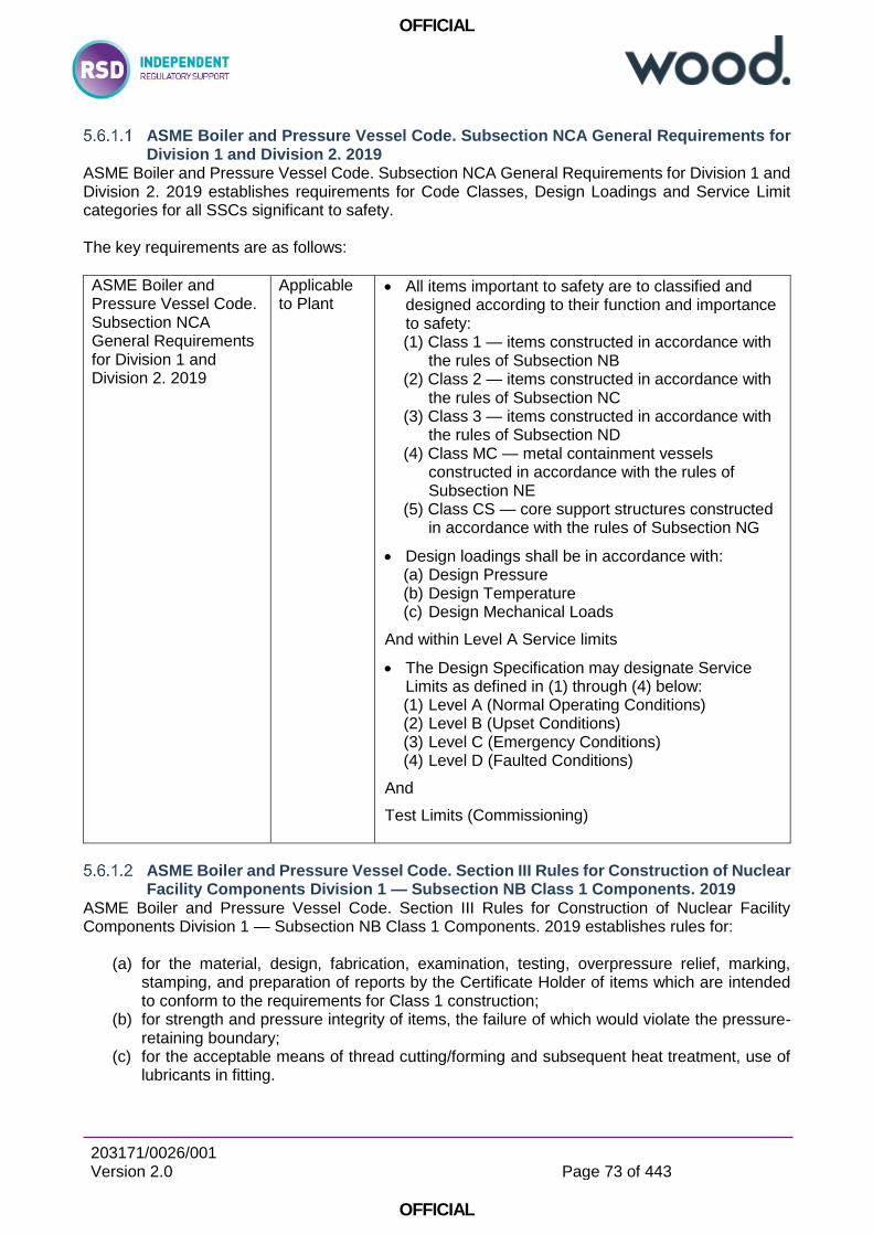
OFFICIAL
203171/0026/001 Version 2.0
Page 73 of 443
OFFICIAL
ASME Boiler and Pressure Vessel Code. Subsection NCA General Requirements for Division 1 and Division 2. 2019
ASME Boiler and Pressure Vessel Code. Subsection NCA General Requirements for Division 1 and Division 2. 2019 establishes requirements for Code Classes, Design Loadings and Service Limit categories for all SSCs significant to safety. The key requirements are as follows:
ASME Boiler and Pressure Vessel Code. Subsection NCA General Requirements for Division 1 and Division 2. 2019
Applicable to Plant
All items important to safety are to classified and designed according to their function and importance to safety: (1) Class 1 — items constructed in accordance with
the rules of Subsection NB (2) Class 2 — items constructed in accordance with
the rules of Subsection NC (3) Class 3 — items constructed in accordance with
the rules of Subsection ND (4) Class MC — metal containment vessels
constructed in accordance with the rules of Subsection NE
(5) Class CS — core support structures constructed in accordance with the rules of Subsection NG
Design loadings shall be in accordance with: (a) Design Pressure (b) Design Temperature (c) Design Mechanical Loads
And within Level A Service limits
The Design Specification may designate Service Limits as defined in (1) through (4) below: (1) Level A (Normal Operating Conditions) (2) Level B (Upset Conditions) (3) Level C (Emergency Conditions) (4) Level D (Faulted Conditions)
And
Test Limits (Commissioning)
ASME Boiler and Pressure Vessel Code. Section III Rules for Construction of Nuclear Facility Components Division 1 — Subsection NB Class 1 Components. 2019
ASME Boiler and Pressure Vessel Code. Section III Rules for Construction of Nuclear Facility Components Division 1 — Subsection NB Class 1 Components. 2019 establishes rules for:
(a) for the material, design, fabrication, examination, testing, overpressure relief, marking, stamping, and preparation of reports by the Certificate Holder of items which are intended to conform to the requirements for Class 1 construction;
(b) for strength and pressure integrity of items, the failure of which would violate the pressure-retaining boundary;
(c) for the acceptable means of thread cutting/forming and subsequent heat treatment, use of lubricants in fitting.
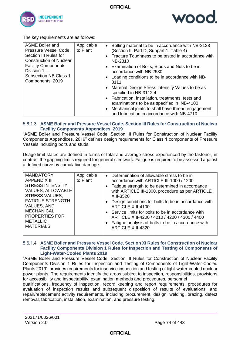
OFFICIAL
203171/0026/001 Version 2.0
Page 74 of 443
OFFICIAL
The key requirements are as follows:
ASME Boiler and Pressure Vessel Code. Section III Rules for Construction of Nuclear Facility Components Division 1 — Subsection NB Class 1 Components. 2019
Applicable to Plant
Bolting material to be in accordance with NB-2128 (Section II, Part D, Subpart 1, Table 4)
Fracture Toughness to be tested in accordance with NB-2310
Examination of Bolts, Studs and Nuts to be in accordance with NB-2580
Loading conditions to be in accordance with NB-3111
Material Design Stress Intensity Values to be as specified in NB-3112.4
Fabrication, installation, treatments, tests and examinations to be as specified in NB-4100
Mechanical joints to shall have thread engagement and lubrication in accordance with NB-4710
ASME Boiler and Pressure Vessel Code. Section III Rules for Construction of Nuclear Facility Components Appendices. 2019
“ASME Boiler and Pressure Vessel Code. Section III Rules for Construction of Nuclear Facility Components Appendices. 2019” defines design requirements for Class 1 components of Pressure Vessels including bolts and studs. Usage limit states are defined in terms of total and average stress experienced by the fastener, in contrast the gapping limits required for general steelwork. Fatigue is required to be assessed against a defined curve by cumulative damage.
MANDATORY APPENDIX III STRESS INTENSITY VALUES, ALLOWABLE STRESS VALUES, FATIGUE STRENGTH VALUES, AND MECHANICAL PROPERTIES FOR METALLIC MATERIALS
Applicable to Plant
Determination of allowable stress to be in accordance with ARTICLE III-1000 / 1200
Fatigue strength to be determined in accordance with ARTICLE III-1300, procedure as per ARTICLE XIII-3520
Design conditions for bolts to be in accordance with ARTICLE XIII-4100
Service limits for bolts to be in accordance with ARTICLE XIII-4200 / 4210 / 4220 / 4300 / 4400
Fatigue analysis of bolts to be in accordance with ARTICLE XIII-4320
ASME Boiler and Pressure Vessel Code. Section XI Rules for Construction of Nuclear Facility Components Division 1 Rules for Inspection and Testing of Components of Light-Water-Cooled Plants 2019
“ASME Boiler and Pressure Vessel Code. Section III Rules for Construction of Nuclear Facility Components Division 1 Rules for Inspection and Testing of Components of Light-Water-Cooled Plants 2019” provides requirements for inservice inspection and testing of light‑water-cooled nuclear power plants. The requirements identify the areas subject to inspection, responsibilities, provisions for accessibility and inspectability, examination methods and procedures, personnel qualifications, frequency of inspection, record keeping and report requirements, procedures for evaluation of inspection results and subsequent disposition of results of evaluations, and repair/replacement activity requirements, including procurement, design, welding, brazing, defect removal, fabrication, installation, examination, and pressure testing.

OFFICIAL
203171/0026/001 Version 2.0
Page 75 of 443
OFFICIAL
In addition to rules applicable by class to all SSCs with additional specific rules for threaded fasteners.
ASME Boiler and Pressure Vessel Code. Section XI Rules for Construction of Nuclear Facility Components Division 1 Rules for Inspection and Testing of Components of Light-Water-Cooled Plants 2019
Applicable to Plant
Components (including bolts) within the scope of the code shall be included in the in-service inspection plan in accordance with IWA-1310
Application of inspection rules to appropriate to the components Classification (Class 1 Subsection IWB, Class 2 Subsection IWC etc.) as per IWA-1320
Pre-service examination and inspection in accordance with IWB-2000
Class 1 Inspection schedule in accordance with IWB-2400: o Pressure retaining bolting greater than 2 in.
diameter Examination Category B-G-1 o Pressure retaining bolting less than 2 in. diameter
Examination Category B-G-2
5.6.2 Structural Design Codes Applicable to Transport Packages (and other Nuclear Structures Important to Safety)
Current typically applied codes and standards used to support Transport Applications are as recommended in TCSC 1006 (Reference G1):
BS 2573 Part 3 (stress limits in normal and accidental lifting conditions) or BS EN 13001-3-1
BS EN 1993-1-9 Design of steel structures – Part 1-0: Fatigue (transport fatigue) or BS 7608 2015
Current Design Codes used in the Assessment and Management of Transport Packages (UK)
5.6.2.1.1 BRITISH STANDARD. Rules for the design of cranes — Part 1: Specification for classification, stress calculations and design criteria for structures. BS 2573-1:1983
BS 2573 Part 1 defines rules for the design of cranes and is applicable to structures comprised of weldable structural steels compliant to BS4360 (superseded by BS EN 10025), and can justifiably be applied to other grades of steels with similar mechanical properties. Stainless steel structures are not within scope. Bolts are required to be accordance with BS 4395 (approximately equivalent to Grade 8.8/10.9). Stainless steel bolts are not within scope. BS 2573 Part 1 requirements for bolts are defined in terms of limits to applied stress, as opposed to total stress, for shear and separating forces. Target bolt preload is recommended to be between 70% and 80% of the bolt yield stress and basic applied tensile stresses are limited to 40% of the bolt yield stress. Since individual bolts see little apparent load until applied load exceeds preload, then it is implicit that the application of BS 2573 Part 1 results in a margin on gapping, rather than actual stress in bolts. BS 2573 Part 1 is superseded by BS EN 13001 and as such is no longer being maintained or up dated with emergent good practice, but remains in prevalent use due to its simplicity of application. However, as superseded, it represents a snap-shot of good practice at its time of publication.
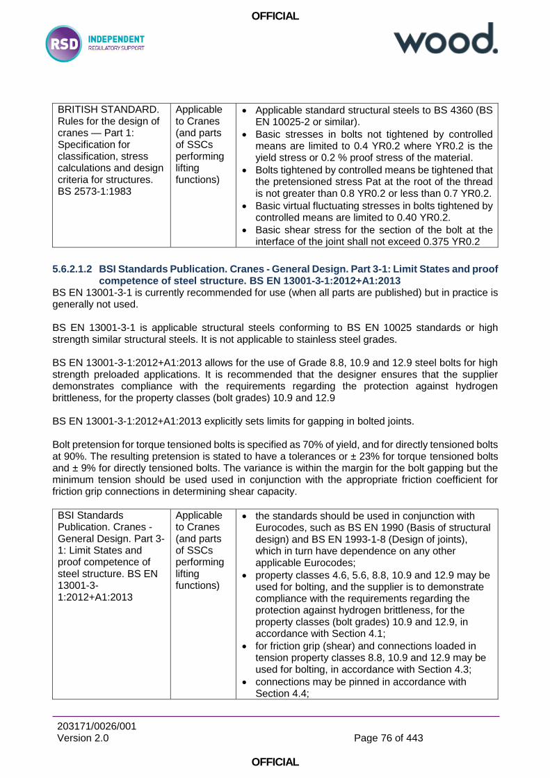
OFFICIAL
203171/0026/001 Version 2.0
Page 76 of 443
OFFICIAL
BRITISH STANDARD. Rules for the design of cranes — Part 1: Specification for classification, stress calculations and design criteria for structures. BS 2573-1:1983
Applicable to Cranes (and parts of SSCs performing lifting functions)
Applicable standard structural steels to BS 4360 (BS EN 10025-2 or similar).
Basic stresses in bolts not tightened by controlled means are limited to 0.4 YR0.2 where YR0.2 is the yield stress or 0.2 % proof stress of the material.
Bolts tightened by controlled means be tightened that the pretensioned stress Pat at the root of the thread is not greater than 0.8 YR0.2 or less than 0.7 YR0.2.
Basic virtual fluctuating stresses in bolts tightened by controlled means are limited to 0.40 YR0.2.
Basic shear stress for the section of the bolt at the interface of the joint shall not exceed 0.375 YR0.2
5.6.2.1.2 BSI Standards Publication. Cranes - General Design. Part 3-1: Limit States and proof competence of steel structure. BS EN 13001-3-1:2012+A1:2013
BS EN 13001-3-1 is currently recommended for use (when all parts are published) but in practice is generally not used. BS EN 13001-3-1 is applicable structural steels conforming to BS EN 10025 standards or high strength similar structural steels. It is not applicable to stainless steel grades. BS EN 13001-3-1:2012+A1:2013 allows for the use of Grade 8.8, 10.9 and 12.9 steel bolts for high strength preloaded applications. It is recommended that the designer ensures that the supplier demonstrates compliance with the requirements regarding the protection against hydrogen brittleness, for the property classes (bolt grades) 10.9 and 12.9 BS EN 13001-3-1:2012+A1:2013 explicitly sets limits for gapping in bolted joints. Bolt pretension for torque tensioned bolts is specified as 70% of yield, and for directly tensioned bolts at 90%. The resulting pretension is stated to have a tolerances or ± 23% for torque tensioned bolts and ± 9% for directly tensioned bolts. The variance is within the margin for the bolt gapping but the minimum tension should be used used in conjunction with the appropriate friction coefficient for friction grip connections in determining shear capacity.
BSI Standards Publication. Cranes - General Design. Part 3-1: Limit States and proof competence of steel structure. BS EN 13001-3-1:2012+A1:2013
Applicable to Cranes (and parts of SSCs performing lifting functions)
the standards should be used in conjunction with Eurocodes, such as BS EN 1990 (Basis of structural design) and BS EN 1993-1-8 (Design of joints), which in turn have dependence on any other applicable Eurocodes;
property classes 4.6, 5.6, 8.8, 10.9 and 12.9 may be used for bolting, and the supplier is to demonstrate compliance with the requirements regarding the protection against hydrogen brittleness, for the property classes (bolt grades) 10.9 and 12.9, in accordance with Section 4.1;
for friction grip (shear) and connections loaded in tension property classes 8.8, 10.9 and 12.9 may be used for bolting, in accordance with Section 4.3;
connections may be pinned in accordance with Section 4.4;

OFFICIAL
203171/0026/001 Version 2.0
Page 77 of 443
OFFICIAL
design and load checks should be in accordance with Section 5.2.3;
design preloading should be Fp,d = 0,7× fyb × As, where f yb is the yield stress (nominal value) of the bolt material and As is the stress area of the bolt, and varaiation is to be considered (± 23%);
calculation of bolt loading to be in accordance with Section 5.2.3.3 (and consider stiffness of connected parts).
5.6.2.1.3 BRITISH STANDARD. Eurocode 3: Design of steel structures — Part 1-9: Fatigue. BS EN 1993-1-9:2005, Incorporating corrigenda December 2005, September 2006 and April 2009
BS EN 1993-1-9 is consistent with the Euronorm suite of design codes and provides guidance on fatigue design of bolted assemblies using the nominal stress method. The method is readily applicable as it allows relatively simplistic modelling, with local stress concentration factors incorporated into a range of fatigue curves. The rules contained within are applicable when steelwork is executed in accordance with BS EN 1090, which specifies the quality of steelwork execution and standards of bolts. Joints should be designed in accordance with BS EN 1993-1-8. The standard should not therefore be applied in isolation and until the requirements of the normative reference standards are satisfied. Therefore, use in conjunction with BS 2573 Part 1, as recommended by TCSC 1006, cannot be considered to be a consistent set of standards, or a combination that necessarily ensures good performance and safety.
BRITISH STANDARD. Eurocode 3: Design of steel structures — Part 1-9: Fatigue. BS EN 1993-1-9:2005, Incorporating corrigenda December 2005, September 2006 and April 2009
Applicable to steel and stainless structures
rules are applicable to structures where execution conforms with EN 1090 and to all grades of structural steels, stainless steels and unprotected weathering steels
Stress ranges to be calculated in accordance paragraph 6.1
Fatigues strength curve to be selected from Table 8.1 Detail 50 or 100.
5.6.2.1.4 BSI Standards Publication. Guide to fatigue design and assessment of steel products. BS 7608:2014+A1:2015
BS 7606 2014 may be used for arbitrary steel and stainless steel fabrications and for the fatigue analysis of bolts and bolted joints. Quality requirements are contained in Section 14 and so the code may be better used in isolation if the specified quality requirements are met at a minimum The method used for bolts is readily applicable being dependent on basic stresses and requires good understanding of the axial pre-load in the bolts so that a true stress range can be determined. The key requirements are:
BSI Standards Publication. Guide to fatigue design and assessment of steel
Applicable to steel and stainless structures
Fatigue assessment to be performed in accordance with high level procedure given in Section 5

OFFICIAL
203171/0026/001 Version 2.0
Page 78 of 443
OFFICIAL
products. BS 7608:2014+A1:2015
Classification of bolts should be in accordance with Table 2, which assigns a fatigue strength and appropriate S-N curve.
Quality and NDE to be in accordance with Section 14.3
Bolt tension to be determined using the method in Section 14.3.3, which may requirement measurement
Axial stress to be determined as per method in Section 15.8
Allowable fatigue stress to be determined using method given in Section 16.
5.6.2.1.5 BRITISH STANDARD Guide to design considerations on The strength of screw threads BS 3580:1964
BS 3580 relates to applications of triangular (V-form) screw threads where strength considerations have to be borne in mind. It is intended to draw the attention of designers to the principal strength factors to be considered in following out details of a design, with some mention of measures which may be adopted to improve strengths. The guide has been largely based on results obtained with steel components and while many of the considerations will apply to other materials, care should be exercised in the interpretation of certain data. BS 3580:1964 specifies:
BRITISH STANDARD Guide to design considerations on The strength of screw threads BS 3580:1964
Applicable to steel bolts to BS 1083
Rules applicable to finished steel hexagon bolts and buts to BS 1083.
Factors affecting fatigue and limit strength such as manufacturing process.
Equations which may be used for internal and external thread stripping load and shank ultimate tensile loads, accounting for locked in torsional stress arising from torque tightening, as per Appendix A
Equations relating applied torque to resulting tension, noting sensitivity to friction conditions and other factors, T=P0.D/5 ± 20% as per Appendix B
Consistent and Comprehensive Applicable Design Codes Available for the Assessment and Management of Transport Packages (UK)
5.6.2.2.1 BRITISH STANDARD. Eurocode — Basis of structural design. BS EN 1990:2002 +A1:2005 Incorporating corrigenda December 2008 and April 2010
The objectives of the Eurocode suite match very closely with those for nuclear safety, and requirements for, structural integrity, serviceability, impact, human error, hazard avoidance, reliability management, execution, inspection and durability. Specific Eurocodes for design are referenced dependent on action or construction material:
EN 1991 Eurocode 1: Actions on structures
EN 1992 Eurocode 2: Design of concrete structures

OFFICIAL
203171/0026/001 Version 2.0
Page 79 of 443
OFFICIAL
EN 1993 Eurocode 3: Design of steel structures
EN 1994 Eurocode 4: Design of composite steel and concrete structures
EN 1995 Eurocode 5: Design of timber structures
EN 1996 Eurocode 6: Design of masonry structures
EN 1997 Eurocode 7: Geotechnical design
EN 1998 Eurocode 8: Design of structures for earthquake resistance
EN 1999 Eurocode 9: Design of aluminium structures Each of the Eurocodes have a number of Parts, for example BS EN 1993 is divided into:
EN 1993-1-1 Design of Steel Structures: General rules and rules for buildings.
EN 1993-1-2 Design of Steel Structures: Structural fire design.
EN 1993-1-3 Design of Steel Structures: Cold-formed members and sheeting.
EN 1993-1-4 Design of Steel Structures: Stainless steels.
EN 1993-1-5 Design of Steel Structures: Plated structural elements.
EN 1993-1-6 Design of Steel Structures: Strength and stability of shell structures.
EN 1993-1-7 Design of Steel Structures: Strength and stability of planar plated structures transversely loaded.
EN 1993-1-8 Design of Steel Structures: Design of joints.
EN 1993-1-9 Design of Steel Structures: Fatigue strength of steel structures.
EN 1993-1-10 Design of Steel Structures: Selection of steel for fracture toughness and through-thickness properties.
EN 1993-1-11 Design of Steel Structures: Design of structures with tension components made of steel.
EN 1993-1-12 Design of Steel Structures: Supplementary rules for high strength steel. The Eurocode suite forms a complete and comprehensive guide to the design of steel structures, containing detailed advice appropriate to type of structure, construction materials, construction method, load action and environment.
5.6.2.2.2 BSI Standards Publication. Execution of steel structures and aluminium structures Part 1: Requirements for conformity assessment of structural components BS EN 1090-1:2009+A1
BS EN 1090-1 is the high level document for steelwork execution in the structural Eurocodes. Subordinate and more detailed Eurocodes, facilitating the assessment and safe execution of steel, stainless steel and stainless steel structures, are referenced. BS EN 1090-1 specifies requirements for conformity assessment of performance characteristics for structural steel and aluminium components as well as for kits placed on the market as construction products. The conformity assessment covers the manufacturing characteristics, and where appropriate the structural design characteristics. This European Standard covers also the conformity assessment of steel components used in composite steel and concrete structures. BS EN 1090-1 refers to BS EN 1090-2 for all matters relating to the design, manufacture, inspection and marking of structural components, including mechanical fasteners. Key themes are here summarised:

OFFICIAL
203171/0026/001 Version 2.0
Page 80 of 443
OFFICIAL
BSI Standards Publication. Execution of steel structures and aluminium structures Part 1: Requirements for conformity assessment of structural components BS EN 1090-1:2009+A1
Applicable to steel, stainless and aluminium structures
Rules are applicable to all structural metallic materials and structural calculations are to be in accordance with the appropriate Eurocode.
The required structural characteristics shall be achieved by: o an adequate structural design, if and as required
for the component, and o manufacturing the component according to the
component specification developed in accordance with EN 1090-2 or EN 1090-3.
5.6.2.2.3 BSI Standards Publication. Execution of steel structures and aluminium structures Part 2: Technical requirements for steel structures. BS EN 1090‑2:2018
BS EN 1090-2 is identified as providing detailed good guidance for steel structures and the use of mechanical fasteners in structural components. BS EN 1090-2 is consistent with and refers to more specific guidance in BS 14399 (all parts). BS EN 1090-2 contains guidance to achieve high quality bolted connections which robustly assure the achievement of the design assumptions and dependent bolted connection performance. Preloaded bolted assemblies are ideally executed using standardised fastener combinations (bolt, washers and thread) supplied to BS 14399-2, which are delivered with a known k-factor (the coefficient of the torque tension relationship). Should the design deviate from the standard combination of materials or surface interactions then the bolts should be considered “special” and the k-factor should be determined by the test specified in Annex H. Stainless steel joints and or stainless fasteners are generally not considered suitable for preloading due to the mechanical properties of the material, and if used should be considered as “special”. BS EN 1090-2 specifies:
BSI Standards Publication. Execution of steel structures and aluminium structures Part 2: Technical requirements for steel structures. BS EN 1090‑2:2018
Applicable to steel and stainless steel structures
rules are applicable to structural steels and stainless steels as listed in Section 2.1
materials of bolts and property classes for bolts which generally fall within its rules, by reference to BS EN 14399 all parts) & BS EN 898-2
The constructor shall have a written Quality Plan in accordance with Section 4.
Identification, inspection documents and traceability should be as per Section 5.2
Corrosion protection of fasteners as per Section 5.6.1 o Hot dip galvanized coatings of fasteners shall conform to EN
ISO 10684 o Non-electrolytically applied zinc flake coatings of fasteners
shall conform to EN ISO 10683
Requirements for non-preloaded applications: o Carbon steel, alloy steel and stainless steel structural bolting
assemblies for non-preloaded applications shall conform to the requirements of the EN 15048 series or BS EN 14399
o Fasteners according to EN ISO 898-1 and EN ISO 898-2 shall generally not be used to join stainless steels according to the EN 10088-4 and EN 10088-5
Requirements for preloaded applications: o Fasteners shall conform to BS EN 14399 series
OFFICIAL
203171/0026/001 Version 2.0
Page 81 of 443
OFFICIAL
o High strength bolting assemblies for preloading shall be used without alteration to the as-delivered lubrication unless DTI method or the procedure in Annex H is adopted.
o Bolting assemblies should discarded after every use. o Stainless steel bolting assemblies shall not be used in
preloaded applications unless otherwise specified. If used they shall be considered as special fasteners
o Direct tension indicators according BS EN 14399-9 may be used.
o Preloaded assemblies do not require additional locking devices
o Preloaded assemblies should be tightened to 0,7 fub As (70% of ultimate breaking load)
o Torque reference values to be calculated from k-class (a system friction relationship between torque and tension, supplied by the manufacturer), as per Section 8.5.3 – 8.5.6
o Preloaded assemblies should be tightened to one the methods in Section 8.5:
1) Torque method - The bolting assemblies shall be tightened using a torque wrench
2) Combined method – a first step to a specified torque followed by a second step to a part turn
3) HRC method – using a shear bolt and special shear wrench in accordance with BS EN 14399-10
4) Direct tension indicator method – using a special crushable washer in accordance with BS EN 14399-9
Requirements for locking devices: o For the prevention of loosening, prevailing torque nuts from
EN ISO 7040, EN ISO 7042, EN ISO 7719 and EN ISO 10511 and the performance requirements given in EN ISO 2320 may be used
o Preloaded assemblies do not require additional locking devices
Requirements for Special Fasteners: o Resin injection bolts should be considered as special
fasteners o Threaded stud or tapped blind holes, stainless steel bolts,
tapped holes in stainless steel structures and lubricants different to the as supplied standard are examples of special fasteners
o Suitability for preloading to be demonstrated in accordance with test procedure in Annex H (BS EN 14399-2)
Dimensions / execution of holes should be as Section 6.6
Galling and seizure of stainless steels and avoidance of seizure as per Section 8.9: o Use of dissimilar stainless steel grades o Anti-galling agents such as PTFE dry film spray o Use of anti-galling grades of stainless steel
Inspections: o Inspection before tightening as per Execution Class in
accordance with Section 12.5.2.3 o Inspection of non-preloaded bolted connections as Section
12.5.1

OFFICIAL
203171/0026/001 Version 2.0
Page 82 of 443
OFFICIAL
o Inspection and testing of preloaded bolted connections: 1) Inspection and sampling dependent on Execution
Class and Tightening method 2) Torque method as per Section 12.5.2.5 – carried out
12-72 hours after final completion, torque at least 105% of specification
3) Combined method as per Section 12.5.2.6 – similar to assembly
4) HRC as per Section as per Section 12.5.2.7 5) Direct tension indicator method as per Section
12.5.2.8
geometry and materials of bolts, washers and threads which should be considered special and subject to supplementary rules and testing
rules for non-preloaded connections and pre-loaded connection (shear and tension)
methods for reliable determining target tightening torque for standard property classes and combinations of standard nuts, washers and bolts
methods for reliable tightening/tensioning and installation of mechanical fasteners
5.6.2.2.4 BSI Standards Publication. Execution of steel structures and aluminium structures Part 3: Part 3: Technical requirements for aluminium structures. BS EN 1090‑3:2019
BS EN 1090-3 is identified as providing detailed good guidance for Aluminium structures and the use of mechanical fasteners in structural components. BS EN 1090-2 is consistent with and refers to more specific guidance in BS 14399 (all parts). BS EN 1090-3 contains guidance to achieve high quality bolted connections which robustly assure the achievement of the design assumptions and dependent bolted connection performance. BS EN 1090-3 specifies:
BSI Standards Publication. Execution of steel structures and aluminium structures Part 3: Part 3: Technical requirements for aluminium structures. BS EN 1090‑3:2019
Applicable to Aluminium structures
Rules are applicable to structural steels and stainless steels as listed in Section 2 and 5.1
Rules are applicable dependent on Execution Class
The Constructor shall have written Quality Documentation and a Quality Plan in accordance with Section 4.2
Non-preloaded bolted assemblies: o should be tightened in accordance with Section 8.3.1 o should use locking devices as necessary o should use a neutral lubricant
Preloaded bolted assemblies: o Nuts, bolts and washers should be in accordance with BS
EN 14399 o Should be tightened in accordance with Section 8.3.2 and to
0.7 fub AS (70% of the ultimate breaking load) o All joints shall be tightened once more after a period of 72
hours
Inspection should be in accordance with Section 12.5
OFFICIAL
203171/0026/001 Version 2.0
Page 83 of 443
OFFICIAL
5.6.2.2.5 BRITISH STANDARD. Eurocode 3: Design of steel structures — Part 1-8: Design of joints. BS EN 1993-1-8:2005
BS EN 1993-1-8 gives design methods for the design of joints in steel structures, subject to predominantly static loading using steel grades S235, S275, S355, S420, S450 and S460. The design methods assume that the standard of construction is as specified in the execution standards given in the suite of Euronorms (including BS EN 14399 for specifications of bolts) and that the construction materials and products used are those specified in EN 1993 or in the relevant material and product specifications.
BRITISH STANDARD. Eurocode 3: Design of steel structures — Part 1-8: Design of joints. BS EN 1993-1-8:200
Applicable to joints in steel structures
All joints should satisfy the design requirements of BS EN 1993-1-1 and from structural steel grades
non-preloaded (category D) bolted connections o fastener property classes 4.6 up to and including 10.9 o not be used where the connections are frequently
subjected to variations of tensile loading
preloaded (category C) bolted connections o fastener property classes 8.8 and 10.9 o controlled tightening in conformity with 1.2.7 o design checks for these connections are summarized in
Table 3.2 o preload should be as per 3.6.1 (Fp,Cd = 0,7 fub As / γM7)
5.6.2.2.6 BSI Standards Publication. High-strength structural bolting assemblies for preloading Part 1: General requirements BS EN 14399-1:2015
BS EN 13499-1 specifies the general requirements for bolt/nut/washer(s) assemblies for high strength structural bolting, which are suitable for preloading. BS EN 14399 forms a suite of harmonised standards governing the use of high strength bolts:
EN 14399-2:2015, is a guide determining the suitability for preloading, including test methods for demonstrating the torque-tension relation with variation;
EN 14399-3:2015, is a guide for the specifications of System HR – Hexagon bolt and nut assemblies, commonly used in the UK;
EN 14399-4:2015, is a guide for System HV – Hexagon bolt and nut assemblies, not commonly used in the UK;
EN 14399-5, is a guide for the specification of Plain washers;
EN 14399-6, is a guide for the specification of Plain chamfered washers;
EN 14399-7:2007, is a guide for the specification of System HR - Countersunk head bolt and nut assemblies, not commonly used in nuclear applications;
EN 14399-8:2007, is a guide for the specification of System HV - Hexagon fit bolt and nut assemblies, not commonly used in the UK;
EN 14399-9:2009, is a guide for the specification of System HR or HV - Direct tension indicators for bolt and nut assemblies;
EN 14399-10:2009, is a guide for the specification of System HRC – Bolt and nut assemblies with calibrated preload;
BS EN 14399-1 states that the requirement for the determination of the k factor (a proportionality constant) for the relationship of tension to applied torque for a specific bolt type. Specific subsection guides are referred to for the determination of the relationship and specifications of bolt and nut system, plain washers, direction tension indicating (crush) washers and directly tension bolt systems.

OFFICIAL
203171/0026/001 Version 2.0
Page 84 of 443
OFFICIAL
Key requirements specified by BS EN 14399-1:
BSI Standards Publication. High-strength structural bolting assemblies for preloading Part 1: General requirements BS EN 14399-1:2015
Applicable to joints in steel structures
High-strength structural bolting assemblies in accordance with EN 14399-2 to EN 14399-10 are designed to fulfil the requirements of this European Standard.
High-strength structural bolting assemblies are suitable for preloading in accordance with EN 1090-2 in steel structures.
Fastener systems (combinations of bolts, washers & nuts) should have a manufacturer specified k-class, which expresses in a concise way the ability of the bolting assemblies to be tightened by the torque control.
Fastener systems (combinations of bolts, washers & nuts) should have a manufacturer specified k-factor, which is the proportionality constant for the torque-tension relationship.
method or combined method by means of the k-factor.
Determination of k-class and k-factor should be as per tests specified BS EN 14399-2
Direct tension indicators (crush washers) conforming to BS EN 14399-9 may be used to directly set bolt tension during assembly.
HRC bolts (shear neck) conforming to BS EN 14399-9 may be used to directly set bolt tension during assembly.
Standard fasteners should conform to the requirements of BS EN 14399-3/5/6.
5.6.2.2.7 BSI Standards Publication. High-strength structural bolting assemblies for preloading Part 2: Suitability for preloading BS EN 14399-2:2015
Preloading in bolted assemblies is very sensitive to differences in manufacture and lubrication. Beside the mechanical properties of the components, the functionality of the bolting assemblies requires that the specified preload can be achieved if the bolting assemblies are tightened with a suitable procedure. BS EN 14399-2 specifies the technical requirements for high-strength structural bolting assemblies in order to ensure the suitability for preloading of bolted connections in metallic structures. A suitability test is specified to check the behaviour of the structural bolting assemblies so as to ensure that the required preload can be reliably obtained by the tightening methods specified in EN 1090-2 with sufficient margins against overtightening and against failure. BS EN 14399-2 defines a standard of characterisation to be applied by the manufacturer to determine the torque-tension relation and variation. Key requirement of BS EN 14399-2:
BSI Standards Publication. High-strength structural bolting assemblies for preloading Part 2: Suitability for preloading BS EN 14399-2:2015
Applicable to preloaded joints in steel structures
Bolts and nuts should be Grade 8.8 or 10.9 as per section 5.1
Marking of bolts should be as per Section 5
k-class, k-factor and k-variance to be determined by the manufacturer in accordance with the method in Section 6
Method should be used for special fasteners requiring preloading

OFFICIAL
203171/0026/001 Version 2.0
Page 85 of 443
OFFICIAL
5.6.2.2.8 BSI Standards Publication. High-strength structural bolting assemblies for preloading Part 3: Part 3: System HR — Hexagon bolt and nut assemblies BS EN 14399-3:2015
BS EN 14399-3 specifies, together with EN 14399-1 and EN 14399-2, the requirements for assemblies of high-strength structural bolts and nuts of system HR suitable for preloaded joints with large widths across flats, thread sizes M12 to M36 and property classes 8.8/8 or 8.8/10 and 10.9/10. Bolting assemblies in accordance with this document have been designed to allow preloading of at least 0,7 fub × As) according to EN 1993-1-8 (Eurocode 3) and to obtain ductility predominantly by plastic elongation of the bolt. For this purpose the components have the following characteristics:
— normal nut height (style 1), see EN ISO 4032;
— thread length of the bolt according to ISO 888.
Bolting assemblies in accordance with this document include washers according to EN 14399-6 or to EN 14399-5 (under the nut only). BS EN 14399-3 defines:
BSI Standards Publication. High-strength structural bolting assemblies for preloading Part 3: Part 3: System HR — Hexagon bolt and nut assemblies BS EN 14399-3:2015
Applicable to preloaded joints in steel structures
Mechanical properties as per table 1;
geometric standards for bolts and nuts according to the HR system commonly used in the UK, as per Section 4;
standards for designation and marking as per Section 3;
requirements for proof loads as per Section 4;
standards for clamp and grip lengths as per Annex A.
5.6.2.2.9 BSI Standards Publication. High-strength structural bolting assemblies for preloading Part 5: Plain washers BS EN 14399-5:2015
BS EN 14399-2 specifies, together with EN 14399-1 and EN 14399-2, hardened and tempered plain washers intended for bolting assemblies with large series hexagon high-strength structural bolts and nuts with threads from M12 to M36 inclusive. Washers according to this standard can be applied under the nut only. For plain washers BS EN 14399-5 defines standards for:
BSI Standards Publication. High-strength structural bolting assemblies for preloading Part 5: Plain washers BS EN 14399-5:2015
Applicable to joints in steel structures
Dimensions in accordance with Section 3;
Specification for mechanical properties in accordance with Section 4;
Designation in accordance with Section 5;
Marking in accordance with Section 6.
5.6.2.2.10 BSI Standards Publication. High-strength structural bolting assemblies for preloading Part 6: Part 6: Plain chamfered washers BS EN 14399-6:2015
BS EN 14399-6 specifies, together with EN 14399-1 and EN 14399-2, hardened and tempered chamfered plain washers with chamfer intended for bolting assemblies with large series hexagon highstrength structural bolts and nuts with thread sizes from M12 to M36 inclusive. For plain chamfered washers BS EN 14399-6 defines standards for:

OFFICIAL
203171/0026/001 Version 2.0
Page 86 of 443
OFFICIAL
BSI Standards Publication. High-strength structural bolting assemblies for preloading Part 6: Part 6: Plain chamfered washers BS EN 14399-6:2015
Applicable to preloaded joints in steel structures
Dimensions in accordance with Section 3;
Specification for mechanical properties in accordance with Section 4;
Designation in accordance with Section 5;
Marking in accordance with Section 6.
5.6.2.2.11 BSI Standards Publication. High-strength structural bolting assemblies for preloading Part 9: System HR or HV - Direct tension indicators for bolt and nut assemblies BS EN 14399-9:2018
BS EN 14399-9 document specifies, together with EN 14399-1 and EN 14399-2, the requirements for direct tension indicators, nut face washers (HN) and bolt face washers (HB) as part of high-strength structural bolting assemblies suitable for preloaded joints. These direct tension indicators are specified as part of high-strength structural bolting assemblies of system HR or HV in accordance with EN 14399-3, EN 14399-4, EN 14399-7 or EN 14399-8, with nominal thread sizes M12 up to and including M36 and property classes 8.8/8 or 8.8/10 and 10.9/10. It specifies two property designations H8 and H10 for direct tension indicators, together with general dimensions, tolerances, materials and functional property/ies. Bolting assemblies in accordance with this document have been designed to allow preloading of at least 0,7 fub × As according to EN 1993-1-8 (Eurocode 3) and to obtain ductility predominantly by plastic elongation of the bolt for system HR in accordance with EN 14399-3 or EN 14399-7. BS EN 14399-9 defines standards for, and methods for assembly of, Direct Tension Indicators which may be used to show that a defined preload is achieved in bolting assemblies. Direct tension indicators (known formerly as load indicating washers) used in conjunction with nut face washers (HN) and bolt face washers (HB) are load indicating devices which are placed under the bolt head or under the nut. The direct tension indicators have protrusions on one face which compress under load and thus may be used to indicate that at least the required preload has been achieved in the bolting assembly. The generic design of BS EN 14399-9 DTI is as per Figure 1 from Ref. F22:
OFFICIAL
203171/0026/001 Version 2.0
Page 87 of 443
OFFICIAL
Key requirements of BS EN 14399-9:
BSI Standards Publication. High-strength structural bolting assemblies for preloading Part 9: System HR or HV - Direct tension indicators for bolt and nut assemblies BS EN 14399-9:2018
Applicable to preloaded joints in steel structures
Dimensions should be as per Section 3.2;
Specifications should be as per Section 3.4;
Function tests (performed by the manufacturer) and characteristics should be as per Sections 4 & 5;
Tightening and use of feeler gauges to determine correct fitting and tensioning of fastener system (performed during assembly) should be as per Section 5.2;
Bolting configurations and detailed tightening procedures should be as per Annex A.
5.6.2.2.12 BSI Standards Publication. High-strength structural bolting assemblies for preloading Part 10: System HRC - Bolt and nut assemblies with calibrated preload BS EN 14399-10:2018
BS EN 14399-10 defines standards for Tension Control Bolts. BS EN 14399-10 specifies, together with EN 14399-1 and EN 14399-2, the requirements for assemblies of high-strength structural bolts and nuts of system HRC suitable for preloaded joints, with hexagon head (large width across flats), cup head or countersunk head, thread sizes M12 to M36 and property class 10.9/10. Bolting assemblies in accordance with this document have been designed to allow preloading of at least 0,7 fub × As) according to EN 1993-1-8 (Eurocode 3) and to obtain ductility predominantly by plastic elongation of the bolt. For this purpose the components have the following characteristics:
— regular nut height according to style 1, see EN ISO 4032; or
— nut with height m = 1 D;
— thread length of the bolt according to ISO 888. Bolting assemblies in accordance with this document include washers according to EN 14399-6 or to EN 14399-5 (under the nut only). Tension Control Bolts come with their own tension control device (spline) to ensure dependable and repeatable tension levels are achieved with each installation. They are installed with a special shear wrench, which turns the nut whilst reacting the torque against the spline which shears off when the proper torque level has been achieved. The generic geometry of a hexagonal head HRC bolts is shown in Figure 1 from Ref. F23.

OFFICIAL
203171/0026/001 Version 2.0
Page 88 of 443
OFFICIAL
BE EN 14399-10 defines standards for:
BSI Standards Publication. High-strength structural bolting assemblies for preloading Part 10: System HRC - Bolt and nut assemblies with calibrated preload BS EN 14399-10:2018
Applicable to joints in steel structures
Dimensions should be as per Section 3.2;
Specifications should be as per Section 3.4;
Function tests (performed by the manufacturer) and characteristics should be as per Sections 4 & 5;
Tightening and use of feeler gauges to determine correct fitting and tensioning of fastener system (performed during assembly) should be as per Section 5.2;
Bolting configurations and detailed tightening procedures should be as per Annex A.
5.6.2.2.13 BSI Standards Publication. Non-preloaded structural bolting assemblies Part 1: General requirements BS EN 15048-1:2016
BS EN 15048-1 specifies the general requirements for bolting assemblies for non-preloaded structural bolting. Bolting assemblies in accordance with this European Standard are designed to be used in structural bolting connections for shear and/or tensile loading. The intended use of bolting assemblies in accordance with this European standard is structural metallic works. It applies to bolts (the term used when bolts partially threaded, screws, studs and stud-bolts are considered all together) and nuts made of carbon steel, alloy steel, stainless steel or aluminium or aluminium alloy with the following property classes:
— bolts made of carbon steel or alloy steel: 4.6, 4.8, 5.6, 5.8, 6.8, 8.8, 10.9 (in accordance with EN ISO 898-1);
— nuts made of carbon steel or alloy steel: 5, 6, 8, 10, 12 (in accordance with EN ISO 898-2);
— bolts made of austenitic stainless steel: 50, 70, 80 (in accordance with EN ISO 3506-1);
— nuts made of austenitic stainless steel: 50, 70, 80 (in accordance with EN ISO 3506-2);
— bolts made of aluminium or aluminium alloy: AL1 to AL6 (in accordance with EN 28839);
— nuts made of aluminium or aluminium alloy: AL1 to AL6 (in accordance with EN 28839)
OFFICIAL
203171/0026/001 Version 2.0
Page 89 of 443
OFFICIAL
BS EN 15048-1 key requirements:
BSI Standards Publication. Non-preloaded structural bolting assemblies Part 1: General requirements BS EN 15048-1:2016
Applicable to non-preloaded joints in steel structures
Product standards for non-preloaded bolts, which may be manufactured from carbon steel or alloy steel, property classes 4.6, 4.8, 5.6, 5.8, 6.8, 8.8, 10.9 (in accordance with EN ISO 898-1), and aluminium bolts;
Minimum mechanical properties by property class, as per Section 4;
Type testing requirements as per Section 5
Prevailing torque in accordance with EN ISO 2320 and EN ISO 7040, EN ISO 7041, EN ISO 7042 or EN ISO 7719 may be used as per Section 5.2.
Technical, designation & marking requirements to BS EN 15048-2
5.6.2.2.14 BSI Standards Publication. Fasteners — Prevailing torque steel nuts — Functional properties BS EN ISO 2320:2015
Prevailing-torque locking fasteners have a self-contained feature which creates frictional interference between the threads of the mating components and are therefore not free-running and may prevent loosening of non-preloaded joints. BS EN ISO 2320 defines standards to which prevailing torque locking fasteners should conform for:
BSI Standards Publication. Fasteners — Prevailing torque steel nuts — Functional properties BS EN ISO 2320:2015
Applicable to non-preloaded joints in all structures
Threads in accordance ISO 965-2 except for the prevailing torque feature with Section 5
Lubrication may applied at the option of the manufacturer in accordance with Section 6
Mechanical Properties shall conform to ISO 898-2
Functional requirements, including friction and clamp forces as per Section 8
Testing, including measures for higher temperature applications as per Section 9.
OFFICIAL
203171/0026/001 Version 2.0
Page 90 of 443
OFFICIAL
6 Appendices
6.1 Reviews of Relevant IAEA Safety Standards
Reference: A1
Document Title/Version Number: IAEA Safety Standards. Fundamental Safety Principles. Safety Fundamental No. SF-1 (2006)
Date of Issue: 2006
Document Review Status: “The text was approved for promulgation as a Safety Fundamentals publication by the IAEA’s Board of Governors in September 2006, and this Safety Fundamentals publication thus becomes the primary publication in the IAEA Safety Standards Series, superseding the previous Safety Fundamentals publications issued in the former Safety Series.” Document Scope:
“The fundamental safety objective applies to all circumstances that give rise to radiation risks. The safety principles are applicable, as relevant, throughout the entire lifetime of all facilities and activities — existing and new — utilized for peaceful purposes” “‘Facilities’ includes: nuclear facilities; irradiation installations; some mining and raw material processing facilities such as uranium mines; radioactive waste management facilities; and any other places where radioactive materials are produced, processed, used, handled, stored or disposed of — or where radiation generators are installed — on such a scale that consideration of protection and safety is required. ‘Activities’ includes: the production, use, import and export of radiation sources for industrial, research and medical purposes; the transport of radioactive material; the decommissioning of facilities; radioactive waste management activities such as the discharge of effluents; and some aspects of the remediation of sites affected by residues from past activities.”
Summary: The document objective states that:
“1.8. The objective of this publication is to establish the fundamental safety objective, safety principles and concepts that provide the bases for the IAEA’s safety standards and its safety related programme. Related requirements are established in the Safety Requirements publications. Guidance on meeting these requirements is provided in the related Safety Guides.”
Key Requirements Section 2 Safety Objectives states that:
“The fundamental safety objective is to protect people and the environment from harmful effects of ionizing radiation.
2.1. This fundamental safety objective of protecting people — individually and collectively — and the environment has to be achieved without unduly limiting the operation of facilities or the conduct of activities that give rise to radiation risks. To ensure that facilities are operated and activities conducted so as to achieve the highest standards of safety that can reasonably be achieved, measures have to be taken:
(a) To control the radiation exposure of people and the release of radioactive material to the environment;
(b) To restrict the likelihood of events that might lead to a loss of control over a nuclear reactor core, nuclear chain reaction, radioactive source or any other source of radiation;
(c) To mitigate the consequences of such events if they were to occur.
OFFICIAL
203171/0026/001 Version 2.0
Page 91 of 443
OFFICIAL
2.2. The fundamental safety objective applies for all facilities and activities, and for all stages over the lifetime of a facility or radiation source, including planning, siting, design, manufacturing, construction, commissioning and operation, as well as decommissioning and closure. This includes the associated transport of radioactive material and management of radioactive waste. 2.3. Ten safety principles have been formulated, on the basis of which safety requirements are developed and safety measures are to be implemented in order to achieve the fundamental safety objective. The safety principles form a set that is applicable in its entirety; although in practice different principles may be more or less important in relation to particular circumstances, the appropriate application of all relevant principles is required.” Principle 5: Optimization of protection states that:
“Protection must be optimized to provide the highest level of safety that can reasonably be achieved.
3.21. The safety measures that are applied to facilities and activities that give rise to radiation risks are considered optimized if they provide the highest level of safety that can reasonably be achieved throughout the lifetime of the facility or activity, without unduly limiting its utilization. 3.22. To determine whether radiation risks are as low as reasonably achievable, all such risks, whether arising from normal operations or from abnormal or accident conditions, must be assessed (using a graded approach) a priori and periodically reassessed throughout the lifetime of facilities and activities. Where there are interdependences between related actions or between their associated risks (e.g. for different stages of the lifetime of facilities and activities, for risks to different groups or for different steps in radioactive waste management), these must also be considered. Account also has to be taken of uncertainties in knowledge. 3.23. The optimization of protection requires judgements to be made about the relative significance of various factors, including:
—The number of people (workers and the public) who may be exposed to radiation;
—The likelihood of their incurring exposures;
—The magnitude and distribution of radiation doses received;
—Radiation risks arising from foreseeable events;
—Economic, social and environmental factors. The optimization of protection also means using good practices and common sense to avoid radiation risks as far as is practical in day to day activities. 3.24. The resources devoted to safety by the licensee, and the scope and stringency of regulations and their application, have to be commensurate with the magnitude of the radiation risks and their amenability to control. Regulatory control may not be needed where this is not warranted by the magnitude of the radiation risks.” Principle 8: Prevention of accidents states that:
“All practical efforts must be made to prevent and mitigate nuclear or radiation accidents. 3.30. The most harmful consequences arising from facilities and activities have come from the loss of control over a nuclear reactor core, nuclear chain reaction, radioactive source or other source of radiation. Consequently, to ensure that the likelihood of an accident having harmful consequences is extremely low, measures have to be taken:
OFFICIAL
203171/0026/001 Version 2.0
Page 92 of 443
OFFICIAL
—To prevent the occurrence of failures or abnormal conditions (including breaches of security) that could lead to such a loss of control;
—To prevent the escalation of any such failures or abnormal conditions that do occur;
—To prevent the loss of, or the loss of control over, a radioactive source or other source of radiation.
3.31. The primary means of preventing and mitigating the consequences of accidents is ‘defence in depth’. Defence in depth is implemented primarily through the combination of a number of consecutive and independent levels of protection that would have to fail before harmful effects could be caused to people or to the environment. If one level of protection or barrier were to fail, the subsequent level or barrier would be available. When properly implemented, defence in depth ensures that no single technical, human or organizational failure could lead to harmful effects, and that the combinations of failures that could give rise to significant harmful effects are of very low probability. The independent effectiveness of the different levels of defence is a necessary element of defence in depth.” Key Themes The document sets out the very highest safety objectives and Regulation of the nuclear industry. In the application of subsequent General and Specific Safety Regulation it is vital to continuously consider the high-level Fundament Principles and objectives of Safety. All matters relating to structural integrity, including the design, integrity, usage and maintenance of bolted joints may have a significant contribution to the achievement of the Fundamental Safety Principles. The document states the objectives of safety as being:
in terms of radiological protection;
and control over nuclear reactors. Safety shall be assured for all stages over the lifetime of a facility or radiation source. The standard of safety shall be the highest level that can reasonably achieved. A graded approach dependent on consequence, defence in depth and consideration of uncertainties are fundamental principles in safety. The optimisation of protection may be achieved by the proportionate application of a relevant Good Practice.
OFFICIAL
203171/0026/001 Version 2.0
Page 93 of 443
OFFICIAL
Reference: A2
Document Title/Version Number: IAEA Safety Standards. Governmental, Legal and Regulatory Framework for Safety. General Safety Requirements No. GSR Part 1 (Rev. 1)
Date of Issue: 2016
Document Review Status:
The Preface states: The IAEA Action Plan on Nuclear Safety (GOV/2011/59-GC(55)/14) was developed in response to the Fukushima Daiichi accident1 and was approved by the IAEA Board of Governors and endorsed by the IAEA General Conference in September 2011 (GC(55)/RES/9). It includes an action headed: Review and strengthen IAEA Safety Standards and improve their implementation. Subsequently “the CSS approved, at its meeting in October 2012, a proposal for a revision process by amendment for the following five Safety Requirements publications: Governmental, Legal and Regulatory Framework for Safety (IAEA Safety Standards Series No. GSR Part 1, 2010); Safety Assessment for Facilities and Activities (GSR Part 4, 2009); Safety of Nuclear Power Plants: Design (SSR-2/1, 2012); Safety of Nuclear Power Plants: Commissioning and Operation (SSR-2/2, 2011); and Site Evaluation for Nuclear Installations (NS-R-3, 2003).”
The revisions to GSR Part 1 relate to the following main areas:
- Independence of the regulatory body; - Prime responsibility for safety; - Emergency preparedness and response; - International obligations and arrangements for international cooperation; - Liaison between the regulatory body and authorized parties; - Review and assessment of information relevant to safety; - Communication and consultation with interested parties.
Scope: 1.5. This Safety Requirements publication covers the essential aspects of the governmental and legal framework for establishing a regulatory body and for taking other actions necessary to ensure the effective regulatory control of facilities and activities — existing and new — utilized for peaceful purposes
The term ‘facilities’ includes: nuclear facilities; irradiation installations; some mining and raw material processing facilities, such as uranium mines; radioactive waste management facilities; and any other places where radioactive materials are produced, processed, used, handled, stored or disposed of — or where radiation generators are installed — on such a scale that consideration of protection and safety is required. The term ‘activities’ includes the production, use, import and export of radiation sources for industrial, research and medical purposes; the transport of radioactive material; the decommissioning of facilities; radioactive waste management activities such as the discharge of effluents; and some aspects of the remediation of sites affected by residues from past activities. Summary: Safety Requirements are “an integrated and consistent set of Safety Requirements establishes the requirements that must be met to ensure the protection of people and the environment, both now and in the future. The requirements are governed by the objective and principles of the Safety Fundamentals. If the requirements are not met, measures must be taken to reach or restore the required level of safety.” Key Requirements OBJECTIVE
OFFICIAL
203171/0026/001 Version 2.0
Page 94 of 443
OFFICIAL
1.4. The objective of this Safety Requirements publication is to establish requirements in respect of the governmental, legal and regulatory framework for safety. The framework for safety is to be established for the entire range of facilities and activities, from the use of a limited number of radiation1 sources to a nuclear power programme.
Requirement 5: Prime responsibility for safety The government shall expressly assign the prime responsibility for safety to the person or organization responsible for a facility or an activity, and shall confer on the regulatory body the authority to require such persons or organizations to comply with stipulated regulatory requirements, as well as to demonstrate such compliance.
Requirement 6: Compliance with regulations and responsibility for safety The government shall stipulate that compliance with regulations and requirements established or adopted by the regulatory body does not relieve the person or organization responsible for a facility or an activity of its prime responsibility for safety.
Requirement 6: Compliance with regulations and responsibility for safety states: 2.14 …. The authorized party has the responsibility for verifying that products and services meet its expectations (e.g. in terms of completeness, validity or robustness) and that they comply with regulatory requirements.
2.15. The prime responsibility for safety shall extend to all stages in the lifetime of facilities and the duration of activities, until their release from regulatory control, i.e. to site evaluation, design, construction, commissioning, operation, shutdown and decommissioning (or closure in the case of disposal facilities for radioactive waste) of facilities. This prime responsibility for safety includes, as appropriate, responsibility for the management of radioactive waste and the management of spent fuel, and responsibility for the remediation of contaminated areas. It also includes responsibility for activities in which radioactive material and radioactive sources are produced, used, stored, transported or handled.
And
2.17. For ensuring safety in the transport of radioactive material, reliance is placed primarily on the performance of packages….. It is the responsibility of the consignor to ensure the appropriate selection of the package and packaging and the mode of transport. Key Themes
GSR Part 1 defines the regulatory framework for the enforcement of safety practices and the responsibilities of regulatory bodies.
The scope of applicability is defined to include all activities, but the means of demonstration may diverge, dependent on activity. The different approaches may influence how bolted joints are designed and verified.
The highest-level distinction in the processes of demonstration of safety for Radioactive Material Transport and other nuclear plant is first made in GSR Part 1.
The responsibility for safety is generally assigned to the authorised body, who retains the prime responsibility for safety throughout the lifetime of facilities and the duration of activities, and shall not delegate this prime responsibility.
For the activity of Radioactive Material Transport the responsibility of safety is assigned to the consignor and demonstration is by primarily reliant of performance of packages. Since responsibilities of the authorised body cannot delegate the responsibility for the safety of Packages and contents used for transport, then responsibility remains with the authorised body within the Authorised site.
OFFICIAL
203171/0026/001 Version 2.0
Page 95 of 443
OFFICIAL
Reference: A3
Document Title/Version Number:
IAEA Safety Standards. Leadership and Management for Safety. General Safety Requirements No. GSR Part 2 (Rev. 1)
Date of Issue: 2016
Document Review Status:-
Document Scope:
SCOPE 1.10. ‘Safety’ encompasses the protection of people and the environment against radiation risks and the safety of facilities and activities that give rise to radiation risks.
1.11. The requirements in this Safety Requirements publication apply to types of facilities and activities that give rise to radiation risks, as follows:
(a) Nuclear installations (including nuclear power plants; research reactors (including subcritical and critical assemblies) and any adjoining radioisotope production facilities; facilities for the storage of spent nuclear fuel; facilities for the enrichment of uranium; nuclear fuel fabrication facilities; conversion facilities; facilities for the reprocessing of spent nuclear fuel; facilities for the predisposal management of radioactive waste arising from nuclear fuel cycle facilities; and nuclear fuel cycle related research and development facilities)
(b) Facilities for the mining or processing of uranium ores or thorium ores;
(c) Irradiation installations;
(d) Facilities and activities for the management (including disposal) of radioactive waste, such as the discharge of effluents, and the remediation of sites affected by residual radioactive material from past activities [7];
(e) Any other places where radioactive material is produced, processed, used, handled, stored or disposed of on such a scale that consideration of protection and safety is required, or where a radiation generator is installed;
(f) Activities involving the production, use, or import and export of sources of ionizing radiation for medical, industrial, agricultural, educational and research purposes;
(g) The transport of radioactive material [8];
(h) The decommissioning (or closure) of facilities [9];
(i) Activities involving the design and manufacture of equipment and other works for and services to facilities or activities that give rise to radiation risks [10];
(j) Industrial activities involving naturally occurring radioactive material that are, or that may be, subject to the requirements for protection and safety.
Summary:
OBJECTIVE 1.9. The objective of this Safety Requirements publication is to establish requirements that support Principle 3 of Fundamental Safety Principles, in relation to establishing, sustaining and continuously improving leadership and management for safety, and an effective management system. This is essential in order to foster and sustain a strong safety culture in an organization. Another objective is to establish requirements that apply Principle 8, which states that “All practical efforts must be made to prevent and mitigate nuclear or radiation accidents.”
Key Requirements:
MANAGEMENT OF PROCESSES AND ACTIVITIES Requirement 10: Management of processes and activities
Processes and activities shall be developed and shall be effectively managed to achieve the organization’s goals without compromising safety.
OFFICIAL
203171/0026/001 Version 2.0
Page 96 of 443
OFFICIAL
4.28. Each process shall be developed and shall be managed to ensure that requirements are met without compromising safety. Processes shall be documented and the necessary supporting documentation shall be maintained. It shall be ensured that process documentation is consistent with any existing documents of the organization. Records to demonstrate that the results of the respective process have been achieved shall be specified in the process documentation. Key Themes:
Processes and activities, such as assembly and tensioning of bolted joints and particularly contributing to safety, shall be developed and shall be effectively managed to achieve the organization’s goals without compromising safety.
The process shall be developed and shall be managed to ensure that requirements are met without compromising safety. The processes shall be documented and the necessary supporting documentation shall be maintained. It shall be ensured that process documentation is consistent with any existing documents of the organization. Records to demonstrate that the results of the respective process have been achieved shall be specified in the process documentation.
OFFICIAL
203171/0026/001 Version 2.0
Page 97 of 443
OFFICIAL
Reference: A4
Document Title/Version Number: IAEA Safety Standards. Radiation Protection and Safety of Radiation Sources: International Basic Safety Standards Part 3. General Safety Requirements No. GSR Part 3.
Date of Issue: 2014
Document Review Status:
“Lessons that may be learned from studying the accident at the Fukushima Daiichi nuclear power plant in Japan following the disastrous earthquake and tsunami of 11 March 2011 will be reflected in this IAEA safety standard as revised and issued in the future.”
Scope:
1.39. These Standards apply for protection against ionizing radiation only, which includes gamma rays, X rays and particles such as beta particles, neutrons, protons, alpha particles and heavier ions.
1.42. These Standards apply to all situations involving radiation exposure that is amenable to control. Exposures deemed to be not amenable to control are excluded from the scope of these Standards
1.43. These Standards establish requirements to be fulfilled in all facilities and activities giving rise to radiation risks. For certain facilities and activities, such as nuclear installations, radioactive waste management facilities and the transport of radioactive material, other safety requirements, complementary to these Standards, also apply.
The term ‘facilities and activities’ is a general term encompassing any human activity that may cause people to be exposed to radiation risks arising from naturally occurring or artificial sources. The term ‘facilities’ includes: nuclear facilities; irradiation installations; some mining and raw material processing facilities such as uranium mines; radioactive waste management facilities; and any other places where radioactive material is produced, processed, used, handled, stored or disposed of — or where radiation generators are installed — on such a scale that consideration of protection and safety is required. The term ‘activities’ includes: the production, use, import and export of radiation sources for industrial, research and medical purposes; the transport of radioactive material; the decommissioning of facilities; radioactive waste management activities such as the discharge of effluents; and some aspects of the remediation of sites affected by residues from past activities. Summary: 1.1. This General Safety Requirements publication, IAEA Safety Standards Series No. GSR Part 3, Radiation Protection and Safety of Radiation Sources: International Basic Safety Standards (hereinafter referred to as ‘these Standards’), is issued in the IAEA Safety Standards Series. It supersedes International Basic Safety Standards for Protection against Ionizing Radiation and for the Safety of Radiation Sources issued in 1996 (the ‘BSS of 1996’)1. Section 1 does not include requirements, but explains the context, concepts and principles for the requirements, which are established in Sections 2–5 and in the schedules. The document is based on the 10 safety principles in Reference A1 and establishes the responsibilities of all organisations involved in safety (be they principal parties, regulatory or governmental). Key Requirements Requirements for Radiation Protection and Safety of Radiation Sources apply in addition to any Specific Safety Requirements, such SSR-6 for Transport activities.
OFFICIAL
203171/0026/001 Version 2.0
Page 98 of 443
OFFICIAL
Requirement 5: Management for protection and safety states: “Human factors 2.52. The principal parties and other parties having specified responsibilities in relation to protection and safety, as appropriate, shall take into account human factors and shall support good performance and good practices to prevent human and organizational failures, by ensuring among other things that:
(a) Sound ergonomic principles are followed in the design of equipment and the development of operating procedures, so as to facilitate the safe operation and use of equipment, to minimize the possibility that operator errors could lead to accidents, and to reduce the possibility that indications of normal conditions and abnormal conditions could be misinterpreted.
(b) Appropriate equipment, safety systems and procedural requirements are provided, and other necessary provision is made:
(i) To reduce, as far as practicable, the possibility that human errors or inadvertent actions could give rise to accidents or to other incidents leading to the exposure of any person; (ii) To provide means for detecting human errors and for correcting them or compensating for them; (iii) To facilitate protective actions and corrective actions in the event of failures of safety systems or failures of measures for protection and safety.”
Requirement 11: Optimization of protection and safety states that the “government or the regulatory body shall establish and enforce requirements for the optimization of protection and safety, and registrants and licensees shall ensure that protection and safety is optimized.” Requirement 13: Safety assessment states that the “regulatory body shall establish and enforce requirements for safety assessment, and the person or organization responsible for a facility or activity that gives rise to radiation risks shall conduct an appropriate safety assessment of this facility or activity.
3.29. The regulatory body shall establish requirements for persons or organizations responsible for facilities and activities that give rise to radiation risks to conduct an appropriate safety assessment. Prior to the granting of an authorization, the responsible person or organization shall be required to submit a safety assessment, which shall be reviewed and assessed by the regulatory body”.
“3.32. The safety assessment shall include, as appropriate, a systematic critical review of:
(b) The ways in which structures, systems and components, including software, and procedures relating to protection and safety might fail, singly or in combination, or might otherwise give rise to exposures, and the consequences of such events;
(d) The ways in which operating procedures relating to protection and safety might be erroneous, and the consequences of such errors;
(g) Any uncertainties or assumptions and their implications for protection and safety.” Requirement 15: Prevention and mitigation of accidents states: “Registrants and licensees shall apply good engineering practice and shall take all practicable measures to prevent accidents and to mitigate the consequences of those accidents that do occur.
Good engineering practice 3.39. The registrant or licensee, in cooperation with other responsible parties, shall ensure that the siting, location, design, manufacture, construction, assembly, commissioning, operation, maintenance and decommissioning (or closure) of facilities or parts thereof are based on good engineering practice which shall, as appropriate:
(a) Take account of international and national standards;
OFFICIAL
203171/0026/001 Version 2.0
Page 99 of 443
OFFICIAL
(b) Be supported by managerial and organizational features, with the purpose of ensuring protection and safety throughout the lifetime of the facility;
(c) Include adequate safety margins in the design and construction of the facility, and in operations involving the facility, so as to ensure reliable performance in normal operation, and take account of the necessary quality, redundancy and capability for inspection, with emphasis on preventing accidents, mitigating the consequences of those accidents that do occur and restricting any possible future exposures;
(d) Take account of relevant developments concerning technical criteria, as well as the results of any relevant research on protection and safety and feedback of information on lessons learned from experience.
Defence in depth 3.40. Registrants and licensees shall ensure that a multilevel (defence in depth) system of sequential, independent provisions for protection and safety that is commensurate with the likelihood and magnitude of potential exposures is applied to sources for which the registrants and licensees are authorized.
Registrants and licensees shall ensure that if one level of protection were to fail, the subsequent independent level of protection would be available. Such defence in depth shall be applied for the purposes of:
(a) Preventing accidents;
(b) Mitigating the consequences of any accidents that do occur;
(c) Restoring the sources to safe conditions after any such accidents. Accident prevention 3.41. Registrants and licensees shall ensure that structures, systems and components, including software, that are related to protection and safety for facilities and activities are designed, constructed, commissioned, operated and maintained so as to prevent accidents as far as reasonably practicable.” Key Themes Reference A4 establishes several potential important principles which may apply the design and execution of bolted connections:
a requirement for human factors to be considered, including the ergonomic design of equipment for safe operation and this may also apply to the possibility of human error;
a requirement for safety to be demonstrated;
a requirement to prevent and mitigate accidents by the application of good engineering practice (codes and standards), adequate safety margins, robust managerial practices and principles of defence in depth.
OFFICIAL
203171/0026/001 Version 2.0
Page 100 of 443
OFFICIAL
Reference: A5
Document Title/Version Number: IAEA Safety Standards. Safety Assessment for Facilities and Activities. General Safety Requirements No. GSR Part 4 (Rev. 1)
Date of Issue: 2016
Document Review Status:
“The revisions to GSR Part 4 relate to the following main areas:
Margins for withstanding external events;
Margins for avoiding cliff edge effects;
Safety assessment for multiple facilities or activities at a single site;
Safety assessment in cases where resources at a facility are shared;
Human factors in accident conditions.” Scope:
“1.6. The requirements, which are derived from the Fundamental Safety Principles [1], relate to any human activity that may cause people to be exposed to radiation risks2 arising from facilities and activities3, as follows.
‘Facilities’ includes:
(a) Nuclear power plants;
(b) Other reactors (such as research reactors and critical assemblies);
(c) Enrichment facilities and fuel fabrication facilities;
(d) Conversion facilities used to generate UF6;
(e) Storage and reprocessing plants for irradiated fuel;
(f) Facilities for radioactive waste management where radioactive waste is treated, conditioned, stored or disposed of;
(g) Any other places where radioactive materials are produced, processed, used, handled or stored;
(h) Irradiation facilities for medical, industrial, research and other purposes, and any places where radiation generators are installed;
(i) Facilities where the mining and processing of radioactive ores (such as ores of uranium and thorium) are carried out.
‘Activities’ includes:
(a) The production, use, import and export of radiation sources for industrial, research, medical and other purposes;
(b) The transport of radioactive material;
(c) The decommissioning and dismantling of facilities and the closure of disposal facilities for radioactive waste;
(d) The close-out of facilities where the mining and processing of radioactive ore was carried out;
(e) Activities for radioactive waste management such as the discharge of effluents;
(f) The remediation of sites affected by residual radioactive material from past activities.” Summary:
“1.3. The objective of this Safety Requirements publication is to establish the generally applicable requirements to be fulfilled in safety assessment for facilities and activities, with special attention paid to defence in depth, quantitative analyses and the application of a graded approach to the ranges of facilities and of activities that are addressed. The publication also addresses the independent verification of the safety assessment that needs to be carried out by the originators and users of the safety assessment.”
OFFICIAL
203171/0026/001 Version 2.0
Page 101 of 443
OFFICIAL
Key Requirements
Requirement 1: Graded approach to safety assessment states:
“A graded approach shall be used in determining the scope and level of detail of the safety assessment carried out at a particular stage for any particular facility or activity, consistent with the magnitude of the possible radiation risks arising from the facility or activity.”
“The main factor to be taken into consideration in the application of a graded approach is that the safety assessment shall be consistent with the magnitude of the possible radiation risks arising from the facility or activity. The approach also takes into account any releases of radioactive material in normal operation, the potential consequences of anticipated operational occurrences and possible accident conditions, and the possibility of the occurrence of very low probability events with potentially high consequences.
Other relevant factors, such as the maturity or complexity of the facility or activity, shall also be taken into account in a graded approach to safety assessment. The consideration of maturity relates to: the use of proven practices and procedures and proven designs; data on operational performance of similar facilities or activities; uncertainties in the performance of the facility or activity; and the continuing and future availability of experienced manufacturers and constructors. Complexity relates to:
The extent and difficulty of the efforts required to construct a facility or to implement an activity; - The number of related processes for which control is necessary; - The extent to which radioactive material has to be handled; - The longevity of the radioactive material; - The reliability and complexity of systems and components; - The accessibility of structures, systems and components for maintenance, inspection, testing and repair. “
Requirement 2: Scope of the safety assessment states: “A safety assessment shall be carried out for all applications of technology that give rise to radiation risks; that is, for all types of facilities and activities”. Requirement 3: Responsibility for the safety assessment states: “The responsibility for carrying out the safety assessment shall rest with the responsible legal person; that is, the person or organization responsible for the facility or activity”. Requirement 4: Purpose of the safety assessment states: “The primary purposes of the safety assessment shall be to determine whether an adequate level of safety has been achieved for a facility or activity and whether the basic safety objectives and safety criteria established by the designer, the operating organization and the regulatory body, in compliance with the requirements for protection and safety as established in Radiation Protection and Safety of Radiation Sources: International Basic Safety Standards, IAEA Safety Standards Series No. GSR Part 3, have been fulfilled.”
And that the “safety assessment for anticipated operational occurrences and accident conditions shall also address failures that might occur and the consequences of any failures.” And the “calculational methods and computer codes that are used to carry out the safety analysis shall be verified, tested and benchmarked as appropriate to build confidence in their use and their suitability for the intended application. This will form part of the supporting evidence presented in the documentation”. Requirement 5: Preparation for the safety assessment states: “The safety criteria defined in national regulations or approved by the regulatory body to be used for judging whether the safety of the facility or activity is adequate have been identified. This could include applicable industrial standards and associated criteria”
OFFICIAL
203171/0026/001 Version 2.0
Page 102 of 443
OFFICIAL
Requirement 7: Assessment of safety functions states: “All safety functions associated with a facility or activity shall be specified and assessed. This includes the safety functions associated with the engineered structures, systems and components, any physical or natural barriers and inherent safety features, as applicable, and any human actions necessary to ensure the safety of the facility or activity.”
And also:
“In the assessment of the safety functions, it shall be determined whether they will be performed with an adequate level of reliability, consistent with the graded approach (see Section 3). It shall be determined in the assessment whether the structures, systems and components and the barriers that are provided to perform the safety functions have an adequate level of reliability, redundancy, diversity, separation, segregation, independence and equipment qualification, as appropriate, and whether potential vulnerabilities have been identified and eliminated.” Requirement 10: Assessment of engineering aspects states: “It shall be determined in the safety assessment whether a facility or activity uses, to the extent practicable, structures, systems and components of robust and proven design.
…it shall be demonstrated whether the structures, systems and components are able to perform their safety functions under the loads induced by normal operation and the anticipated operational occurrences and accident conditions that were taken into account explicitly in the design of the facility.
…It shall be determined in the safety assessment whether the materials used are suitable for their purpose with regard to the standards specified in the design, and for the conditions that arise during normal operation and following anticipated operational occurrences or accident conditions that were taken into account explicitly in the design of the facility or activity. Requirement 11: Assessment of human factors states: “Human interactions with the facility or activity shall be addressed in the safety assessment, and it shall be determined whether the procedures and safety measures that are provided for all normal operational activities, in particular those that are necessary for implementation of the operational limits and conditions, and those that are required for responding to anticipated operational occurrences and to accident conditions, ensure an adequate level of safety.
…This includes those human factors relating to ergonomic design in all areas and to human–machine interfaces where activities are carried out.” Requirement 14: Scope of the safety analysis states: “The performance of a facility or activity in all operational states and, as necessary, in the post-operational phase shall be assessed in the safety analysis”
“The analysis shall be performed to a scope and level of detail that correspond to the magnitude of the radiation risks associated with the facility or activity, the frequency of the events included in the safety analysis, the complexity of the facility or activity, and the uncertainties inherent in the processes that are included in the safety analysis.”
Requirement 15: Deterministic and probabilistic approaches states: “Both deterministic and probabilistic approaches shall be included in the safety analysis.”
“Conservatism in the deterministic approach compensates for uncertainties, such as uncertainties in the performance of equipment and in the performance of personnel, by providing a sufficient safety margin.” Requirement 17: Uncertainty and sensitivity analysis states:
OFFICIAL
203171/0026/001 Version 2.0
Page 103 of 443
OFFICIAL
“Uncertainty and sensitivity analysis shall be performed and taken into account in the results of the safety analysis and the conclusions drawn from it.
The safety analysis incorporates, to varying degrees, predictions of the circumstances that will prevail in the operational or post-operational stages of a facility or activity. There will always be uncertainties associated with such predictions that will depend on the nature of the facility or activity and the complexity of the safety analysis. These uncertainties shall be taken into account in the results of the safety analysis and the conclusions drawn from it.”
“There are two facets to uncertainty: aleatory (or stochastic) uncertainty and epistemic uncertainty. Aleatory uncertainty has to do with events or phenomena that occur in a random manner, such as random failures of equipment. These aspects of uncertainty are inherent in the logical structure of the probabilistic model. Epistemic uncertainty is associated with the state of knowledge relating to a given problem under consideration. In any analysis or analytical model of a physical phenomenon, simplifications and assumptions are made. Even for relatively simple problems, a model may omit some aspects that are deemed unimportant to the solution. Additionally, the state of knowledge within the relevant scientific and engineering disciplines may be incomplete. Simplifications and incompleteness of knowledge give rise to uncertainties in the prediction of outcomes for a specified problem.”
Key Themes
Reference A5 identifies numerous factors important to aspects of bolted joint lifecycle:
Safety assessments should be graded
Safety assessments to be carried for facilities and activities;
The responsibility for carrying out the safety assessment shall rest with the responsible legal person; that is, the person or organization responsible for the facility or activity;
All safety functions associated with a facility or activity shall be specified and assessed;
It shall be determined in the assessment whether the structures, systems and components and the barriers that are provided to perform the safety functions have an adequate level of reliability, redundancy, diversity, separation, segregation, independence and equipment qualification;
All calculational methods and computer codes that are used to carry out the safety analysis shall be verified and this will form part of the supporting evidence presented in the documentation;
It shall be determined in the safety assessment whether a facility or activity uses, to the extent practicable, structures, systems and components of robust and proven design;
It shall be demonstrated whether the materials and structures, systems and components are able to perform their safety functions under the loads induced by normal operation and the anticipated operational occurrences and accident conditions;
Human interactions with the facility or activity shall be addressed in the safety assessment, and it shall be determined whether the procedures and safety measures that are provided for all nor-mal operational activities;
Uncertainties in safety analysis processes should be bounded by conservatisms;
Uncertainties in the performance of equipment and personnel should be bounded by conservatisms;
Uncertainty and sensitivity analysis shall be performed and taken into account in the results of the safety analysis and the conclusions drawn from it.
OFFICIAL
203171/0026/001 Version 2.0
Page 104 of 443
OFFICIAL
Reference: A6
Document Title/Version Number: IAEA Safety Standards. Safety of Nuclear Power Plants: Design. Specific Safety Requirements No. SSR-2/1 (Rev. 1)
Date of Issue: 2016
Document Review Status: The present publication supersedes the Safety Requirements publication Safety of Nuclear Power Plants: Design,1 which was issued in 2012 as IAEA Safety Standards Series No. SSR-2/1.
The revisions to SSR-2/1 relate to the following main areas:
— Prevention of severe accidents by strengthening the design basis for the plant;
— Prevention of unacceptable radiological consequences of a severe accident for the public and the environment;
— Mitigation of the consequences of a severe accident to avoid or to minimize radioactive contamination off the site.
Scope: “1.6. It is expected that this publication will be used primarily for land based stationary nuclear power plants with water cooled reactors designed for electricity generation or for other heat production applications (such as district heating or desalination). This publication may also be applied, with judgement, to other reactor types, to determine the requirements that have to be considered in developing the design.”
Summary: “This publication establishes design requirements for the structures, systems and components of a nuclear power plant, as well as for procedures and organizational processes important to safety that are required to be met for safe operation and for preventing events that could compromise safety, or for mitigating the consequences of such events, were they to occur.”
“This publication is intended for use by organizations involved in design, manufacture, construction, modification, maintenance, operation and decommissioning for nuclear power plants, in analysis, verification and review, and in the provision of technical support, as well as by regulatory bodies.” Key Requirements
“SAFETY IN DESIGN 2.8. To achieve the highest level of safety that can reasonably be achieved in the design of a nuclear power plant, measures are required to be taken to do the following, consistent with national acceptance criteria and safety objectives [1]: (a) To prevent accidents with harmful consequences resulting from a loss of control over the reactor core or over other sources of radiation, and to mitigate the consequences of any accidents that do occur; (b) To ensure that for all accidents taken into account in the design of the installation, any radiological consequences would be below the relevant limits and would be kept as low as reasonably achievable; (c) To ensure that the likelihood of occurrence of an accident with serious radiological consequences is extremely low and that the radiological consequences of such an accident would be mitigated to the fullest extent practicable.
2.9. To demonstrate that the fundamental safety objective … is achieved in the design of a nuclear power plant, a comprehensive safety assessment … of the design is required to be carried out. Its objective is to identify all possible sources of radiation and to evaluate possible doses that could be received by workers at the installation and by members of the public, as well as possible effects on the environment, as a result of operation of the plant. The safety assessment is required in
OFFICIAL
203171/0026/001 Version 2.0
Page 105 of 443
OFFICIAL
order to examine: (i) normal operation of the plant; (ii) the performance of the plant in anticipated operational occurrences; and (iii) accident conditions.”
“THE CONCEPT OF DEFENCE IN DEPTH 2.12. The primary means of preventing accidents in a nuclear power plant and mitigating the consequences of accidents if they do occur is the application of the concept of defence in depth…. This concept is applied to all safety related activities, whether organizational, behavioural or design related, and whether in full power, low power or various shutdown states.”
“There are five levels of defence:
(1) The purpose of the first level of defence is to prevent deviations from normal operation and the failure of items important to safety. This leads to requirements that the plant be soundly and conservatively sited, designed, constructed, maintained and operated in accordance with quality management and appropriate and proven engineering practices. To meet these objectives, careful attention is paid to the selection of appropriate design codes and materials, and to the quality control of the manufacture of components and construction of the plant, as well as to its commissioning. Design options that reduce the potential for internal hazards contribute to the prevention of accidents at this level of defence. Attention is also paid to the processes and procedures involved in design, manufacture, construction, and in-service inspection, maintenance and testing, to the ease of access for these activities, and to the way the plant is operated and to how operating experience is utilized.”
“(2) The purpose of the second level of defence is to detect and control deviations from normal operational states in order to prevent anticipated operational occurrences at the plant from escalating to accident conditions. This is in recognition of the fact that postulated initiating events are likely to occur over the operating lifetime of a nuclear power plant, despite the care taken to prevent them. This second level of defence necessitates the provision of specific systems and features in the design, the confirmation of their effectiveness through safety analysis, and the establishment of operating procedures to prevent such initiating events, or otherwise to minimize their consequences, and to return the plant to a safe state.”
“(3) For the third level of defence, it is assumed that, although very unlikely, the escalation of certain anticipated operational occurrences or postulated initiating events might not be controlled at a preceding level and that an accident could develop. In the design of the plant, such accidents are postulated to occur. This leads to the requirement that inherent and/or engineered safety features, safety systems and procedures be capable of preventing damage to the reactor core or preventing radioactive releases requiring off-site protective actions and returning the plant to a safe state.
(4) The purpose of the fourth level of defence is to mitigate the consequences of accidents that result from failure of the third level of defence in depth. This is achieved by preventing the progression of such accidents and mitigating the consequences of a severe accident. The safety objective in the case of a severe accident is that only protective actions that are limited in terms
of lengths of time and areas of application would be necessary and that off-site contamination would be avoided or minimized. Event sequences that would lead to an early radioactive release or a large radioactive release are required to be ‘practically eliminated’.
(5) The purpose of the fifth and final level of defence is to mitigate the radiological consequences of radioactive releases that could potentially result from accidents. This requires the provision of adequately equipped emergency response facilities and emergency plans and emergency procedures for on-site and off-site emergency response.”
“MANAGEMENT OF SAFETY IN DESIGN Requirement 1: Responsibilities in the management of safety in plant design

OFFICIAL
203171/0026/001 Version 2.0
Page 106 of 443
OFFICIAL
An applicant for a licence to construct and/or operate a nuclear power plant shall be responsible for ensuring that the design submitted to the regulatory body meets all applicable safety requirements.”
“Requirement 2: Management system for plant design The design organization shall establish and implement a management system for ensuring that all safety requirements established for the design of the plant are considered and implemented in all phases of the design process and that they are met in the final design.”
“Requirement 3: Safety of the plant design throughout the lifetime of the plant
The operating organization shall establish a formal system for ensuring the continuing safety of the plant design throughout the lifetime of the nuclear power plant.”
“PRINCIPAL TECHNICAL REQUIREMENTS”
“Requirement 4: Fundamental safety functions Fulfilment of the following fundamental safety functions for a nuclear power plant shall be ensured for all plant states: (i) control of reactivity; (ii) removal of heat from the reactor and from the fuel store; and (iii) confinement of radioactive material, shielding against radiation and control of planned radioactive releases, as well as limitation of accidental radioactive releases.”
“Requirement 6: Design for a nuclear power plant The design for a nuclear power plant shall ensure that the plant and items important to safety have the appropriate characteristics to ensure that safety functions can be performed with the necessary reliability, that the plant can be operated safely within the operational limits and conditions for the full duration of its design life and can be safely decommissioned, and that impacts on the environment are minimized.”
“The design for a nuclear power plant shall be such as to ensure that the safety requirements of the operating organization, the requirements of the regulatory body and the requirements of relevant legislation, as well as applicable national and international codes and standards, are all met, and that due account is taken of human capabilities and limitations and of factors that could influence human performance.”
“Requirement 7: Application of defence in depth The design of a nuclear power plant shall incorporate defence in depth. The levels of defence in depth shall be independent as far as is practicable.”
“Requirement 9: Proven engineering practices Items important to safety for a nuclear power plant shall be designed in accordance with the relevant national and international codes and standards.”
“Requirement 10: Safety assessment Comprehensive deterministic safety assessments and probabilistic safety assessments shall be carried out throughout the design process for a nuclear power plant to ensure that all safety requirements on the design of the plant are met throughout all stages of the lifetime of the plant, and to confirm that the design, as delivered, meets requirements for manufacture and for construction, and as built, as operated and as modified.”
“Requirement 11: Provision for construction Items important to safety for a nuclear power plant shall be designed so that they can be manufactured, constructed, assembled, installed and erected in accordance with established processes that ensure the achievement of the design specifications and the required level of safety.”
“Requirement 13: Categories of plant states
Plant states shall be identified and shall be grouped into a limited number of categories primarily on the basis of their frequency of occurrence at the nuclear power plant.
OFFICIAL
203171/0026/001 Version 2.0
Page 107 of 443
OFFICIAL
5.1. Plant states shall typically cover: (a) Normal operation;
(b) Anticipated operational occurrences, which are expected to occur over the operating lifetime of the plant;
(c) Design basis accidents;
(d) Design extension conditions, including accidents with core melting.”
“Requirement 14: Design basis for items important to safety The design basis for items important to safety shall specify the necessary capability, reliability and functionality for the relevant operational states, for accident conditions and for conditions arising from internal and external hazards, to meet the specific acceptance criteria over the lifetime of the nuclear power plant.”
“Requirement 15: Design limits A set of design limits consistent with the key physical parameters for each item important to safety for the nuclear power plant shall be specified for all operational states and for accident conditions.”
“Requirement 16: Postulated initiating events The design for the nuclear power plant shall apply a systematic approach to identifying a comprehensive set of postulated initiating events such that all foreseeable events with the potential for serious consequences and all foreseeable events with a significant frequency of occurrence are anticipated and are considered in the design.”
“Requirement 16: Postulated initiating events The design for the nuclear power plant shall apply a systematic approach to identifying a comprehensive set of postulated initiating events such that all foreseeable events with the potential for serious consequences and all foreseeable events with a significant frequency of occurrence are anticipated and are considered in the design.”
“Requirement 17: Internal and external hazards All foreseeable internal hazards and external hazards, including the potential for human induced events directly or indirectly to affect the safety of the nuclear power plant, shall be identified and their effects shall be evaluated. Hazards shall be considered in designing the layout of the plant and in determining the postulated initiating events and generated loadings for use in the design of relevant items important to safety for the plant.”
“Requirement 18: Engineering design rules The engineering design rules for items important to safety at a nuclear power plant shall be specified and shall comply with the relevant national or international codes and standards and with proven engineering practices, with due account taken of their relevance to nuclear power technology.”
“Requirement 19: Design basis accidents A set of accidents that are to be considered in the design shall be derived from postulated initiating events for the purpose of establishing the boundary conditions for the nuclear power plant to withstand, without acceptable limits for radiation protection being exceeded.”
“Requirement 22: Safety classification All items important to safety shall be identified and shall be classified on the basis of their function and their safety significance.”
“Requirement 23: Reliability of items important to safety The reliability of items important to safety shall be commensurate with their safety significance.”
“Requirement 24: Common cause failures
The design of equipment shall take due account of the potential for common cause failures of items important to safety, to determine how the concepts of diversity, redundancy, physical separation and functional independence have to be applied to achieve the necessary reliability.”
“Requirement 25: Single failure criterion
OFFICIAL
203171/0026/001 Version 2.0
Page 108 of 443
OFFICIAL
The single failure criterion shall be applied to each safety group incorporated in the plant design.”
“Requirement 26: Fail-safe design The concept of fail-safe design shall be incorporated, as appropriate, into the design of systems and components important to safety.”
“DESIGN FOR SAFE OPERATION OVER THE LIFETIME OF THE PLANT Requirement 29: Calibration, testing, maintenance, repair, replacement, inspection and monitoring of items important to safety
Items important to safety for a nuclear power plant shall be designed to be calibrated, tested, maintained, repaired or replaced, inspected and monitored as required to ensure their capability of performing their functions and to maintain their integrity in all conditions specified in their design basis.”
“The plant layout shall be such that activities for calibration, testing, maintenance, repair or replacement, inspection and monitoring are facilitated and can be performed to relevant national and international codes and standards”
Key Themes
An applicant for a licence to construct and/or operate a nuclear power plant shall be responsible for ensuring that the design submitted to the regulatory body meets all applicable safety requirements;
The operating organization shall establish a formal system for ensuring the continuing safety of the plant design throughout the lifetime of the nuclear power plant;
The design shall ensure confinement of radioactive material, shielding against radiation and control of planned radioactive releases, as well as limitation of accidental radioactive releases;
The design of a nuclear power plant shall incorporate defence in depth concepts;
Risks should be as low as reasonably achievable for normal operation, anticipated operational occurrences and accident conditions;
Items important to safety shall be designed to relevant national and international codes and standards;
Designs shall comply with the Single Failure Criterion and Fail Safe Design Principle;
Items important to safety for a nuclear power plant shall be designed so that they can be manufactured, constructed, assembled, installed and erected in accordance with established processes that ensure the achievement of the design specifications and the required level of safety;
All items important to safety shall be identified and shall be classified on the basis of their function and their safety significance;
The single failure criterion shall be applied to each safety group incorporated in the plant design;
Items important to safety for a nuclear power plant shall be designed to be calibrated, tested, maintained, repaired or replaced, inspected and monitored as required to ensure their capability of performing their functions and to maintain their integrity in all conditions specified in their design basis.
OFFICIAL
203171/0026/001 Version 2.0
Page 109 of 443
OFFICIAL
Reference: A7
Document Title/Version Number: IAEA Safety Standards. Safety of Nuclear Power Plants: Commission and Operation. Specific Safety Requirements No. SSR-2/2 (Rev. 1)
Date of Issue: 2016
Document Review Status: The revisions to SSR 2/2 relate to the following main areas:
Periodic safety review and feedback from operating experience;
Emergency preparedness;
Accident management;
Fire safety. Scope: “1.6. This publication deals with the safe commissioning and operation of a nuclear power plant. It covers commissioning and operation up to the removal of nuclear fuel from the plant, including maintenance and modifications made throughout the lifetime of the plant. It covers the preparation for decommissioning but not the decommissioning phase itself. The publication also establishes additional requirements relating only to commissioning. Normal operation and anticipated operational occurrences as well as accident conditions are taken into account.” Summary: “This publication establishes design requirements for the structures, systems and components of a nuclear power plant, as well as for procedures and organizational processes important to safety that are required to be met for safe operation and for preventing events that could compromise safety, or for mitigating the consequences of such events, were they to occur.” Key Requirements Requirement 8: Performance of safety related activities states that:
“The operating organization shall ensure that safety related activities are adequately analysed and controlled to ensure that the risks associated with harmful effects of ionizing radiation are kept as low as reasonably achievable.”
Requirement 10: Control of plant configuration states that: “The operating organization shall establish and implement a system for plant configuration management to ensure consistency between design requirements, physical configuration and plant documentation.”
“Controls on plant configuration shall ensure that changes to the plant and its safety related systems are properly identified, screened, designed, evaluated, implemented and recorded. Proper controls shall be implemented to handle changes in plant configuration that result: from maintenance work, testing, repair, operational limits and conditions, and plant refurbishment; and from modifications due to ageing of components, obsolescence of technology, operating experience, technical developments and results of safety research.”
Requirement 31: Maintenance, testing, surveillance and inspection programmes states “The operating organization shall ensure that effective programmes for maintenance, testing, surveillance and inspection are established and implemented.
8.1. Maintenance, testing, surveillance and inspection programmes shall be established that include predictive, preventive and corrective maintenance activities.”
“8.5. The frequency of maintenance, testing, surveillance and inspection of individual structures, systems and components shall be determined on the basis of:
(a) The importance to safety of the structures, systems and components, with insights from probabilistic safety assessment taken into account;
OFFICIAL
203171/0026/001 Version 2.0
Page 110 of 443
OFFICIAL
(b) Their reliability in, and availability for, operation; (c) Their assessed potential for degradation in operation and their ageing characteristics; (d) Operating experience; (e) Recommendations of vendors.”
Key Themes SSR 2/2 establishes regulations and requirements for the safe Commissioning and Operation of Nuclear Power Plants. It establishes design requirements for the structures, systems and components of a nuclear power plant, as well as for procedures and organizational processes important to safety that are required to be met for safe operation and for preventing events that could compromise safety, or for mitigating the consequences of such events, were they to occur. Requirements potentially applicable to structural bolted joint and the assembly of bolted connection include:
Controls on plant configuration shall ensure that changes to the plant and its safety related systems are properly identified, screened, designed, evaluated, implemented and recorded. Proper controls shall be implemented to handle changes in plant configuration that result: from maintenance work, testing, repair, operational limits and conditions, and plant refurbishment; and from modifications due to ageing of components, obsolescence of technology, operating experience, technical developments and results of safety research;
Maintenance, testing, surveillance and inspection programmes shall be established that include predictive, preventive and corrective maintenance activities. The frequency of maintenance, testing, surveillance and inspection of individual structures, systems and components shall be determined on the basis of importance, reliability, degradation factors and recommendations of vendors.
OFFICIAL
203171/0026/001 Version 2.0
Page 111 of 443
OFFICIAL
Reference: A8
Document Title/Version Number: IAEA Safety Standards. Regulations for the Safe Transport of Radioactive Material 2018 Edition. Specific Safety Requirements No. SSR-6 (Rev. 1)
Date of Issue: 2018
Document Review Status: Background “101. These Regulations establish standards of safety which provide an acceptable level of control of the radiation, criticality and thermal hazards to people, property and the environment that are associated with the transport of radioactive material. These Regulations are based on: the Fundamental Safety Principles, IAEA Safety Standards Series No. SF-1 [1], jointly sponsored by the European Atomic Energy Community (EAEC), the Food and Agriculture Organization of the United Nations (FAO), the IAEA, the International Labour Organization (ILO), the International Maritime Organization (IMO), the OECD Nuclear Energy Agency (NEA), the Pan American Health Organization (PAHO), the United Nations Environment Programme (UNEP) and the World Health Organization (WHO); Radiation Protection and Safety of Radiation Sources: International Basic Safety Standards, IAEA Safety Standards Series No. GSR Part 3 [2], jointly sponsored by the European Commission (EC), FAO, IAEA, ILO, OECD/NEA, PAHO, UNEP and WHO; Governmental, Legal and Regulatory Framework for Safety, IAEA Safety Standards Series No. GSR Part 1 (Rev. 1) [3]; and Leadership and Management for Safety, IAEA Safety Standards Series No. GSR Part 2 [4]. Thus, compliance with these Regulations is deemed to satisfy the principles of GSR Part 3 [2] in respect of transport. In accordance with SF-1 [1], the prime responsibility for safety must rest with the person or organization responsible for facilities and activities that give rise to radiation risks.” Scope “106. These Regulations apply to the transport of radioactive material by all modes on land, water, or in the air, including transport that is incidental to the use of the radioactive material. Transport comprises all operations and conditions associated with, and involved in, the movement of radioactive material; these include the design, manufacture, maintenance and repair of packaging, and the preparation, consigning, loading, carriage including in-transit storage, shipment after storage, unloading and receipt at the final destination of loads of radioactive material and packages”
“Thus, compliance with these Regulations is deemed to satisfy the principles of GSR Part 3 [2] in respect of transport.”
Summary:
“OBJECTIVE 104. The objective of these Regulations is to establish requirements that must be satisfied to ensure safety and to protect people, property, and the environment from harmful effects of ionizing radiation during the transport of radioactive material. This protection is achieved by requiring:
(a) Containment of the radioactive contents; (b) Control of external dose rate; (c) Prevention of criticality; (d) Prevention of damage caused by heat.
These requirements are satisfied firstly by applying a graded approach to contents limits for packages and conveyances and to performance standards applied to package designs, depending upon the hazard of the radioactive contents. Secondly, they are satisfied by imposing conditions on the design and operation of packages and on the maintenance of packagings, including consideration of the nature of the radioactive contents. Thirdly, they are satisfied by requiring administrative controls, including, where appropriate, approval by competent authorities.
OFFICIAL
203171/0026/001 Version 2.0
Page 112 of 443
OFFICIAL
Finally, further protection is provided by making arrangements for planning and preparing emergency response to protect people, property and the environment.”
Key Requirements “SCOPE 106. These Regulations apply to the transport of radioactive material by all modes on land, water, or in the air, including transport that is incidental to the use of the radioactive material. Transport comprises all operations and conditions associated with, and involved in, the movement of radioactive material; these include the design, manufacture, maintenance and repair of packaging, and the preparation, consigning, loading, carriage including in-transit storage, shipment after storage, unloading and receipt at the final destination of loads of radioactive material and packages. A graded approach is applied in specifying the performance standards in these Regulations, which are characterized in terms of three general severity levels:
(a) Routine conditions of transport (incident free); (b) Normal conditions of transport (minor mishaps); (c) Accident conditions of transport.”
“110. For radioactive material having subsidiary hazards, and for transport of radioactive material with other dangerous goods, the relevant transport regulations for dangerous goods shall apply in addition to these Regulations.”
REQUIREMENTS BEFORE EACH SHIPMENT “503. Before each shipment of any package, it shall be ensured that all the requirements specified in the relevant provisions of these Regulations and in the applicable certificates of approval have been fulfilled. The following requirements shall also be fulfilled, if applicable:
(c) For each Type B(U), Type B(M) and Type C package, it shall be ensured by inspection and/or appropriate tests that all closures, valves and other openings of the containment system through which the radioactive contents might escape are properly closed and, where appropriate, sealed in the manner for which the demonstrations of compliance with the requirements of paras 659 and 671 were made.”
Possession of certificates and instructions 561. The consignor shall have in his/her possession a copy of each certificate required under Section VIII of these Regulations and a copy of the instructions with regard to the proper closing of the package and other preparations for shipment before making any shipment under the terms of the certificates.
Information for carriers 554. The consignor shall provide in the transport documents a statement regarding actions, if any, that are required to be taken by the carrier. The statement shall be in the languages deemed necessary by the carrier or the authorities concerned and shall include at least the following points:
(a) Supplementary requirements for loading, stowage, carriage, handling and unloading of the package, overpack or freight container, including any special stowage provisions for the safe dissipation of heat (see para. 565), or a statement that no such requirements are necessary; (b) Restrictions on the mode of transport or conveyance and any necessary routeing instructions; (c) Emergency arrangements appropriate to the consignment.
“GENERAL REQUIREMENTS FOR ALL PACKAGINGS AND PACKAGES 607. The package shall be so designed in relation to its mass, volume and shape that it can be easily and safely transported. In addition, the package shall be so designed that it can be properly secured in or on the conveyance during transport.
608. The design shall be such that any lifting attachments on the package will not fail when used in the intended manner and that if failure of the attachments should occur, the ability of the
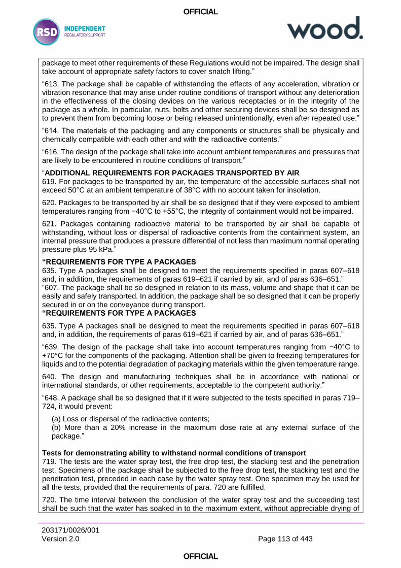
OFFICIAL
203171/0026/001 Version 2.0
Page 113 of 443
OFFICIAL
package to meet other requirements of these Regulations would not be impaired. The design shall take account of appropriate safety factors to cover snatch lifting.”
“613. The package shall be capable of withstanding the effects of any acceleration, vibration or vibration resonance that may arise under routine conditions of transport without any deterioration in the effectiveness of the closing devices on the various receptacles or in the integrity of the package as a whole. In particular, nuts, bolts and other securing devices shall be so designed as to prevent them from becoming loose or being released unintentionally, even after repeated use.”
“614. The materials of the packaging and any components or structures shall be physically and chemically compatible with each other and with the radioactive contents.”
“616. The design of the package shall take into account ambient temperatures and pressures that are likely to be encountered in routine conditions of transport.”
“ADDITIONAL REQUIREMENTS FOR PACKAGES TRANSPORTED BY AIR 619. For packages to be transported by air, the temperature of the accessible surfaces shall not exceed 50°C at an ambient temperature of 38°C with no account taken for insolation.
620. Packages to be transported by air shall be so designed that if they were exposed to ambient temperatures ranging from −40°C to +55°C, the integrity of containment would not be impaired.
621. Packages containing radioactive material to be transported by air shall be capable of withstanding, without loss or dispersal of radioactive contents from the containment system, an internal pressure that produces a pressure differential of not less than maximum normal operating pressure plus 95 kPa.”
“REQUIREMENTS FOR TYPE A PACKAGES 635. Type A packages shall be designed to meet the requirements specified in paras 607–618 and, in addition, the requirements of paras 619–621 if carried by air, and of paras 636–651.” “607. The package shall be so designed in relation to its mass, volume and shape that it can be easily and safely transported. In addition, the package shall be so designed that it can be properly secured in or on the conveyance during transport. “REQUIREMENTS FOR TYPE A PACKAGES
635. Type A packages shall be designed to meet the requirements specified in paras 607–618 and, in addition, the requirements of paras 619–621 if carried by air, and of paras 636–651.”
“639. The design of the package shall take into account temperatures ranging from −40°C to +70°C for the components of the packaging. Attention shall be given to freezing temperatures for liquids and to the potential degradation of packaging materials within the given temperature range.
640. The design and manufacturing techniques shall be in accordance with national or international standards, or other requirements, acceptable to the competent authority.”
“648. A package shall be so designed that if it were subjected to the tests specified in paras 719–724, it would prevent:
(a) Loss or dispersal of the radioactive contents; (b) More than a 20% increase in the maximum dose rate at any external surface of the package.”
Tests for demonstrating ability to withstand normal conditions of transport 719. The tests are the water spray test, the free drop test, the stacking test and the penetration test. Specimens of the package shall be subjected to the free drop test, the stacking test and the penetration test, preceded in each case by the water spray test. One specimen may be used for all the tests, provided that the requirements of para. 720 are fulfilled.
720. The time interval between the conclusion of the water spray test and the succeeding test shall be such that the water has soaked in to the maximum extent, without appreciable drying of
OFFICIAL
203171/0026/001 Version 2.0
Page 114 of 443
OFFICIAL
the exterior of the specimen. In the absence of any evidence to the contrary, this interval shall be taken to be 2 h if the water spray is applied from four directions simultaneously. No time interval shall elapse, however, if the water spray is applied from each of the four directions consecutively.
721. Water spray test: The specimen shall be subjected to a water spray test that simulates exposure to rainfall of approximately 5 cm per hour for at least 1 h.
722. Free drop test: The specimen shall drop onto the target so as to suffer maximum damage in respect of the safety features to be tested:
(a) The height of the drop, measured from the lowest point of the specimen to the upper surface of the target, shall be not less than the distance specified in Table 14 for the applicable mass. The target shall be as defined in para. 717. (b) For rectangular fibreboard or wood packages not exceeding a mass of 50 kg, a separate specimen shall be subjected to a free drop onto each corner from a height of 0.3 m. (c) For cylindrical fibreboard packages not exceeding a mass of 100 kg, a separate specimen shall be subjected to a free drop onto each of the quarters of each rim from a height of 0.3 m.
723. Stacking test: Unless the shape of the packaging effectively prevents stacking, the specimen shall be subjected, for a period of 24 h, to a compressive load equal to the greater of the following:
(a) The equivalent of 5 times the maximum weight of the package; (b) The equivalent of 13 kPa multiplied by the vertically projected area of the package.
The load shall be applied uniformly to two opposite sides of the specimen, one of which shall be the base on which the package would typically rest.
724. Penetration test: The specimen shall be placed on a rigid, flat, horizontal surface that will not move significantly while the test is being carried out:
(a) A bar, 3.2 cm in diameter with a hemispherical end and a mass of 6 kg, shall be dropped and directed to fall with its longitudinal axis vertical onto the centre of the weakest part of the specimen so that if it penetrates sufficiently far it will hit the containment system. The bar shall not be significantly deformed by the test performance. (b) The height of the drop of the bar, measured from its lower end to the intended point of impact on the upper surface of the specimen, shall be 1 m.”
“REQUIREMENTS FOR TYPE B(U) PACKAGES 652. Type B(U) packages shall be designed to meet the requirements specified in paras 607–618, the requirements specified in paras 619–621 if carried by air, and in paras 636–649, except as specified in para. 648(a), and, in addition, the requirements specified in paras 653–666.”
653. A package shall be so designed that, under the ambient conditions specified in paras 656 and 657, heat generated within the package by the radioactive contents shall not, under normal conditions of transport, as demonstrated by the tests in paras 719–724, adversely affect the package in such a way that it would fail to meet the applicable requirements for containment and shielding if left unattended for a period of one week.”
OFFICIAL
203171/0026/001 Version 2.0
Page 115 of 443
OFFICIAL
“659. A package shall be so designed that if it were subjected to: (a) The tests specified in paras 719–724, it would restrict the loss of radioactive contents to not more than 10−6A2 per hour. (b) The tests specified in paras 726, 727(b), 728 and 729 and either the test in:
— Para. 727(c), when the package has a mass not greater than 500 kg, an overall density not greater than 1000 kg/m3 based on the external dimensions, and radioactive contents greater than 1000A2 not as special form radioactive material; or — Para. 727(a), for all other packages. (i) It would retain sufficient shielding to ensure that the dose rate 1 m from the surface of the package would not exceed 10 mSv/h with the maximum radioactive contents that the package is designed to contain.”
Tests for demonstrating ability to withstand accident conditions of transport 726. The specimen shall be subjected to the cumulative effects of the tests specified in paras 727 and 728, in that order. Following these tests, either this specimen or a separate specimen shall be subjected to the effect(s) of the water immersion test(s), as specified in para. 729 and, if applicable, para. 730.
727. Mechanical test: The mechanical test consists of three different drop tests. Each specimen shall be subjected to the applicable drops, as specified in para. 659 or para. 685. The order in which the specimen is subjected to the drops shall be such that, on completion of the mechanical test, the specimen shall have suffered such damage as will lead to maximum damage in the thermal test that follows:
(a) For drop I, the specimen shall drop onto the target so as to suffer maximum damage, and the height of the drop, measured from the lowest point of the specimen to the upper surface of the target, shall be 9 m. The target shall be as defined in para. 717. (b) For drop II, the specimen shall drop onto a bar rigidly mounted perpendicularly on the target so as to suffer maximum damage. The height of the drop, measured from the intended point of impact of the specimen to the upper surface of the bar, shall be 1 m. The bar shall be of solid mild steel of circular cross-section, 15.0 ± 0.5 cm in diameter and 20 cm long, unless a longer bar would cause greater damage, in which case a bar of sufficient length to cause maximum damage shall be used. The upper end of the bar shall be flat and horizontal with its edge rounded off to a radius of not more than 6 mm. The target on which the bar is mounted shall be as described in para. 717. (c) For drop III, the specimen shall be subjected to a dynamic crush test by positioning the specimen on the target so as to suffer maximum damage by the drop of a 500 kg mass from 9 m onto the specimen. The mass shall consist of a solid mild steel plate 1 m × 1 m and shall fall in a horizontal attitude. The lower face of the steel plate shall have its edges and corners rounded off to a radius of not more than 6 mm. The height of the drop shall be measured from the underside of the plate to the highest point of the specimen. The target on which the specimen rests shall be as defined in para. 717.
728. Thermal test: The specimen shall be in thermal equilibrium under conditions of an ambient temperature of 38°C, subject to the solar insolation conditions specified in Table 12 and subject to the design maximum rate of internal heat generation within the package from the radioactive contents. Alternatively, any of these parameters are allowed to have different values prior to, and during, the test, provided due account is taken of them in the subsequent assessment of package response. The thermal test shall then consist of (a) followed by (b).
(a) Exposure of a specimen for a period of 30 min to a thermal environment that provides a heat flux at least equivalent to that of a hydrocarbon fuel–air fire in sufficiently quiescent ambient conditions to give a minimum average flame emissivity coefficient of 0.9 and an average temperature of at least 800°C, fully engulfing the specimen, with a surface absorptivity
OFFICIAL
203171/0026/001 Version 2.0
Page 116 of 443
OFFICIAL
coefficient of 0.8 or that value that the package may be demonstrated to possess if exposed to the fire specified. (b) Exposure of the specimen to an ambient temperature of 38°C, subject to the solar insolation conditions specified in Table 12 and subject to the design maximum rate of internal heat generation within the package by the radioactive contents for a sufficient period to ensure that temperatures in the specimen are decreasing in all parts of the specimen and/or are approaching initial steady state conditions. Alternatively, any of these parameters are allowed to have different values following cessation of heating, provided due account is taken of them in the subsequent assessment of package response. During and following the test, the specimen shall not be artificially cooled and any combustion of materials of the specimen shall be permitted to proceed naturally.
729. Water immersion test: The specimen shall be immersed under a head of water of at least 15 m for a period of not less than 8 h in the attitude that will lead to maximum damage. For demonstration purposes, an external gauge pressure of at least 150 kPa shall be considered to meet these conditions.
Enhanced water immersion test for Type B(U) and Type B(M) packages containing more than 105A2 and Type C packages
730. Enhanced water immersion test: The specimen shall be immersed under a head of water of at least 200 m for a period of not less than 1 h. For demonstration purposes, an external gauge pressure of at least 2 MPa shall be considered to meet these conditions.
Water leakage test for packages containing fissile material
731. Packages for which water in-leakage or out-leakage to the extent that results in greatest reactivity has been assumed for purposes of assessment under paras 680–685 shall be excepted from the water leakage test.
732. Before the specimen is subjected to the water leakage test specified below, it shall be subjected to the tests in para. 727(b) and either para. 727(a) or 727(c), as required by para. 685 and the test specified in para. 728.
733. The specimen shall be immersed under a head of water of at least 0.9 m for a period of not less than 8 h and in the attitude for which maximum leakage is expected.
“REQUIREMENTS FOR TYPE C PACKAGES 669. Type C packages shall be designed to meet the requirements specified in paras 607–621 and 636–649, except as specified in para. 648(a), and the requirements specified in paras 653–657, 661–666 and 670–672.
670. A package shall be capable of meeting the assessment criteria prescribed for tests in paras 659(b) and 663 after burial in an environment defined by a thermal conductivity of 0.33 W/(m·K) and a temperature of 38°C in the steady state. Initial conditions for the assessment shall assume that any thermal insulation of the package remains intact, the package is at the maximum normal operating pressure and the ambient temperature is 38°C.”
Tests for Type C packages 734. Specimens shall be subjected to the effects of the following test sequences:
(a) The tests specified in paras 727(a), 727(c), 735 and 736, in this order; (b) The test specified in para. 737.
Separate specimens are allowed to be used for the sequence in (a) and for (b). 735. Puncture–tearing test: The specimen shall be subjected to the damaging effects of a vertical solid probe made of mild steel. The orientation of the package specimen and the impact point on the package surface shall be such as to cause maximum damage at the conclusion of the test sequence specified in para. 734(a):
OFFICIAL
203171/0026/001 Version 2.0
Page 117 of 443
OFFICIAL
(a) The specimen, representing a package having a mass of less than 250 kg, shall be placed on a target and subjected to a probe having a mass of 250 kg falling from a height of 3 m above the intended impact point. For this test the probe shall be a 20 cm diameter cylindrical bar with the striking end forming the frustum of a right circular cone with the following dimensions: 30 cm height and 2.5 cm diameter at the top with its edge rounded off to a radius of not more than 6 mm. The target on which the specimen is placed shall be as specified in para. 717. (b) For packages having a mass of 250 kg or more, the base of the probe shall be placed on a target and the specimen dropped onto the probe. The height of the drop, measured from the point of impact with the specimen to the upper surface of the probe, shall be 3 m. The probe for this test shall have the same properties and dimensions as specified in (a), except that the length and mass of the probe shall be such as to cause maximum damage to the specimen. The target on which the base of the probe is placed shall be as specified in para. 717.
736. Enhanced thermal test: The conditions for this test shall be as specified in para. 728, except that the exposure to the thermal environment shall be for a period of 60 min.
737. Impact test: The specimen shall be subject to an impact on a target at a velocity of not less than 90 m/s, at such an orientation as to suffer maximum damage. The target shall be as defined in para. 717, except that the target surface may be at any orientation as long as the surface is normal to the specimen path. Key Themes SSR-6 establishes regulations for the safe performance of transport systems for radioactive materials by specifying proof tests and acceptance criteria in terms of radiological containment. The performance requirements are graded dependent on package contents and transport mode. The key performance criteria relating to bolting joint are:
503. Before each shipment of any package, it shall be ensured that all the requirements specified in the relevant provisions of these Regulations and in the applicable certificates of approval have been fulfilled. The following requirements shall also be fulfilled, if applicable: (c) For each Type B(U), Type B(M) and Type C package, it shall be ensured by inspection and/or appropriate tests that all closures, valves and other openings of the containment system through which the radioactive contents might escape are properly closed and, where appropriate, sealed in the manner for which the demonstrations of compliance with the requirements of paras 659 and 671 were made. Bolted joints must therefore be tensioned in the manner assumed in the compliance demonstration. This may require demonstration that the bolt is suitable for pre-tensioning to the assumed tension over repeated use and that sufficiently robust assembly processes are in place to prevent
613. The package shall be capable of withstanding the effects of any acceleration, vibration or vibration resonance that may arise under routine conditions of transport without any deterioration in the effectiveness of the closing devices on the various receptacles or in the integrity of the package as a whole. In particular, nuts, bolts and other securing devices shall be so designed as to prevent them from becoming loose or being released unintentionally, even after repeated use. Bolted joints, in accordance with RGP, should be tensioned sufficiently to prevent loosening, should not relax by cyclic plasticity processes or should be retained by some secondary retention device.
614. The materials of the packaging and any components or structures shall be physically and chemically compatible with each other and with the radioactive contents. Anodic corrosion should not be caused by the interaction of bolts with the package.
640. The design and manufacturing techniques shall be in accordance with national or international standards, or other requirements, acceptable to the competent authority.

OFFICIAL
203171/0026/001 Version 2.0
Page 118 of 443
OFFICIAL
Bolted joints should be designed in accordance with appropriate national or international design codes.
OFFICIAL
203171/0026/001 Version 2.0
Page 119 of 443
OFFICIAL
Reference: C7
Document Title/Version Number:
IAEA Safety Standards. Schedules of Provisions of the IAEA Regulations for the Safe Transport of Radioactive Material (2012 Edition). Specific Safety Guide No. SSG-33. 2012
Date of Issue: 2012
Document Review Status: Document Scope: SCOPE 1.9. This Safety Guide can be used for all transport of radioactive material.
It contains 26 schedules corresponding to the UN numbers and associated proper shipping names for the radioactive material to be shipped.
1.10. The user’s attention is drawn to the fact that there may be deviations (i.e. exceptions and additions) from the Regulations necessitated by national and modal regulations and carrier restrictions, which are not reflected in this Safety Guide.
Summary: BACKGROUND 1.1. The Regulations for the Safe Transport of Radioactive Material (IAEA Safety Standards Series No. SSR-6, 2012 Edition) [1], henceforth called ‘the Regulations’, establish standards of safety that provide an acceptable level of control of the radiation, criticality and thermal hazards to persons, property and the environment that are associated with the transport of radioactive material. Protection from harmful effects of radiation during the transport of radioactive material is achieved by means of a combination of limitations on the contents of a package according to the quantity and type of radioactivity, the package design, and certain simple handling, storage and stowage precautions that are to be followed during transport.
Key Requirements: 1.5. This Safety Guide is prepared on the basis of the Regulations. It reproduces certain parts of the Regulations in a user friendly format for specified types of consignments, classified according to their associated UN numbers, but does not contain any additional requirements. Details, in particular of design, construction and testing of packagings, are omitted.
CLASSIFICATION 2.3. Radioactive material is required to be assigned one of the UN numbers specified in Table 1. The UN number assigned depends on the activity level of the radionuclides contained in the package, the fissile or non-fissile properties of these radionuclides, the type of package, and the nature or form of the radioactive contents of the package, or special arrangements governing the transport operation.
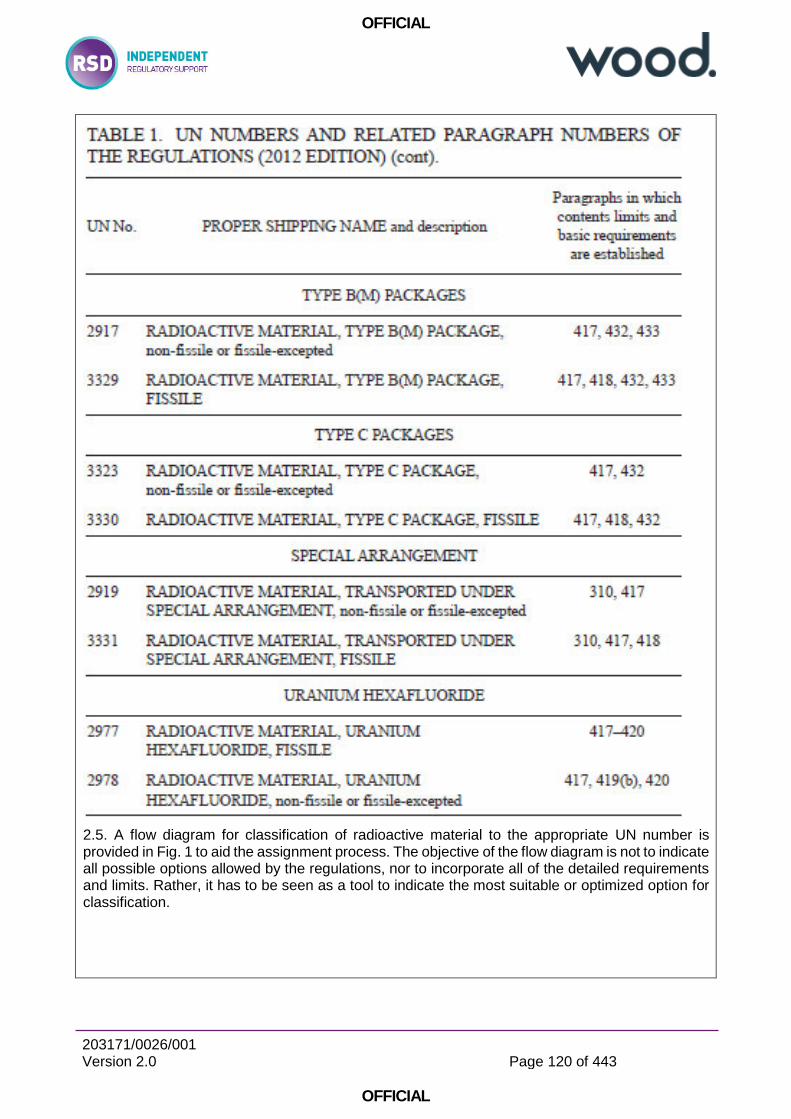
OFFICIAL
203171/0026/001 Version 2.0
Page 120 of 443
OFFICIAL
2.5. A flow diagram for classification of radioactive material to the appropriate UN number is provided in Fig. 1 to aid the assignment process. The objective of the flow diagram is not to indicate all possible options allowed by the regulations, nor to incorporate all of the detailed requirements and limits. Rather, it has to be seen as a tool to indicate the most suitable or optimized option for classification.
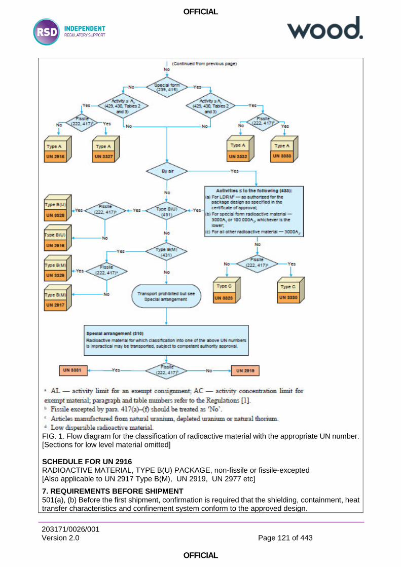
OFFICIAL
203171/0026/001 Version 2.0
Page 121 of 443
OFFICIAL
FIG. 1. Flow diagram for the classification of radioactive material with the appropriate UN number. [Sections for low level material omitted] SCHEDULE FOR UN 2916 RADIOACTIVE MATERIAL, TYPE B(U) PACKAGE, non-fissile or fissile-excepted [Also applicable to UN 2917 Type B(M), UN 2919, UN 2977 etc]
7. REQUIREMENTS BEFORE SHIPMENT 501(a), (b) Before the first shipment, confirmation is required that the shielding, containment, heat transfer characteristics and confinement system conform to the approved design.
OFFICIAL
203171/0026/001 Version 2.0
Page 122 of 443
OFFICIAL
502, 503(a)–(c) Before each shipment of any package, the following requirements apply: (i) For any package, it is required to ensure that all the requirements specified in the relevant provisions of the Regulations have been satisfied. (ii) It is required to ensure that lifting attachments that do not meet the requirements of para. 608 of the Regulations have been removed or otherwise rendered incapable of being used for lifting the package, in accordance with para. 609 of the Regulations. (iii) For each package, it is required to ensure that all the requirements specified in the competent authority approval certificates have been satisfied. (iv) Each package is required to be held until equilibrium conditions have been approached closely enough to demonstrate compliance with the requirements for temperature and pressure unless an exemption from these requirements has received unilateral approval. (v) For each package, it is required to ensure by inspection and/or appropriate tests that all closures, valves and other openings of the containment system through which the radioactive contents might escape are properly closed and, where appropriate, sealed in the manner for which the demonstrations of compliance with the requirements of paras 659 and 671 of the Regulations were made.
Key Themes: The key requirements, highlighted by SSG-33, effecting the connection of bolted joints are:
Packages are classified / graded according to contents and mode
Before the first shipment, confirmation is required that the shielding, containment, heat transfer characteristics and confinement system conform to the approved design;
For each package, it is required to ensure by inspection and/or appropriate tests that all closures, valves and other openings of the containment system through which the radioactive contents might escape are properly closed and, where appropriate, sealed in the manner for which the demonstrations of compliance with the requirements of paras 659 and 671 of the Regulations were made.
It is therefore a requirement that bolted joints must be secured in the manner (and tightness) that was applied in any tests o calculations

OFFICIAL
203171/0026/001 Version 2.0
Page 123 of 443
OFFICIAL
6.2 Reviews of Relevant UK Statute
Reference: B1
Document Title/Version Number:
Energy Act 2013
Date of Issue: 2013
Document Review Status:- Document Scope:- Summary: Energy Act 2013 2013 CHAPTER 32 An Act to make provision for the setting of a decarbonisation target range and duties in relation to it; for or in connection with reforming the electricity market for purposes of encouraging low carbon electricity generation or ensuring security of supply; for the establishment and functions of the Office for Nuclear Regulation; about the government pipe-line and storage system and rights exercisable in relation to it; about the designation of a strategy and policy statement; about domestic supplies of gas and electricity; for extending categories of activities for which energy licences are required; for the making of orders requiring regulated persons to provide redress to consumers of gas or electricity; about offshore transmission of electricity during a commissioning period; for imposing fees in connection with certain costs incurred by the Secretary of State; about smoke and carbon monoxide alarms; and for connected purposes.
Key Requirements: 79 Codes of practice (1) The ONR may, in accordance with section 80—
(a) issue codes of practice giving practical guidance as to the requirements of any provision of the relevant statutory provisions; (b) revise or withdraw a code of practice issued under this section.
(2) A code of practice (including a revised code) must specify the relevant statutory provisions to which it relates. (3) References in this Part to an approved code of practice are references to a code issued under this section as it has effect for the time being. (4) A person’s failure to observe any provision of an approved code of practice does not of itself make the person liable to any civil or criminal proceedings. (5) But subsections (6) to (8) apply to any proceedings for an offence where—
(a) the offence consists of failing to comply with any requirement or prohibition imposed by or under any of the relevant statutory provisions, and (b) at the time of the alleged failure, there was an approved code of practice relating to the provision.
(6) Any provision of the code of practice which appears to the court to be relevant to the alleged offence is admissible in evidence in the proceedings. (7) Where—
(a) in order to establish that the defendant failed to comply with the requirement or prohibition, the prosecution must prove any matter, (b) the court is satisfied that a provision of the code of practice is relevant to that matter, and (c) the prosecution prove that, at a material time, the defendant failed to observe that provision of the code of practice, that matter is to be taken as proved unless the defendant proves that the requirement or prohibition was complied with in some other way.
(8) A document purporting to be an approved code of practice is to be taken to be such an approved code unless the contrary is proved.

OFFICIAL
203171/0026/001 Version 2.0
Page 124 of 443
OFFICIAL
Key Themes: ONR was established as a statutory Public Corporation on 1 April 2014 under the Energy Act 2013 link to external website. It provides the framework of responsibilities and the powers of the organisation. ONR is formally established by Part 3 of the Energy Act, and a Commencement Order brought the relevant sections and the organisation into being.
Reference: B2
Document Title/Version Number:
Health and Safety at Work ect. Act 1974
Date of Issue: 2006
Document Review Status: Document Scope: Summary: An Act to make further provision for securing the health, safety and welfare of persons at work, for protecting others against risks to health or safety in connection with the activities of persons at work, for controlling the keeping and use and preventing the unlawful acquisition, possession and use of dangerous substances, and for controlling certain emissions into the atmosphere; to
make further provision with respect to the employment medical advisory service; to amend the law relating to building regulations, and the Building (Scotland) Act 1959; and for connected purposes.
Key Requirements: General duties
General duties of employers to their employees.
2.-(1) It shall be the duty of every employer to ensure, so far as is reasonably practicable, the health, safety and welfare at work of all his employees.
(2) Without prejudice to the generality of an employer's duty under the preceding subsection, the matters to which that duty extends include in particular-
(a) the provision and maintenance of plant and systems of work that are, so far as is reasonably practicable, safe and without risks to health ; (b) arrangements for ensuring, so far as is reasonably practicable, safety and absence of risks to health in connection with the use, handling, storage and transport of articles and substances ; (c) the provision of such information, instruction, training and supervision as is necessary to ensure, so far as is reasonably practicable, the health and safety at work of his employees ;
3.-(1) It shall be the duty of every employer to conduct his undertaking in such a way as to ensure, so far as is reasonably practicable, that persons not in his employment who may be affected thereby are not thereby exposed to risks to their health employed to persons other or safety.
(2) It shall be the duty of every self-employed person to conduct his undertaking in such a way as to ensure, so far as is reasonably practicable, that he and other persons (not being his employees) who may be affected thereby are not thereby exposed to risks to their health or safety.
(3) In such cases as may be prescribed, it shall be the duty of every employer and every self-employed person, in the prescribed circumstances and in the prescribed manner, to give to persons (not being his employees) who may be affected by the way in which he conducts his

OFFICIAL
203171/0026/001 Version 2.0
Page 125 of 443
OFFICIAL
undertaking the prescribed information about such aspects of the way in which he conducts his undertaking as might affect their health or safety.
Key Themes: The Health and Safety at Work Act 1974 requires that risks shall be “ALARP”.
OFFICIAL
203171/0026/001 Version 2.0
Page 126 of 443
OFFICIAL
Reference: B4, B5, B6, B7, B8 & B9 Document Title/Version Number: The “ALARP 6 Pack”:
Principles and guidelines to assist HSE in its judgements that duty-holders have reduced risk as low as reasonably practicable (http://www.hse.gov.uk/risk/theory/alarp1.htm).
Assessing compliance with the law in individual cases and the use of good practice (http://www.hse.gov.uk/risk/theory/alarp2.htm)
Policy and guidance on reducing risks as low as reasonably practicable in design (http://www.hse.gov.uk/risk/theory/alarp3.htm)
HSE principles for Cost Benefit Analysis (CBA) in support of ALARP decisions (http://www.hse.gov.uk/risk/theory/alarpcba.htm)
Cost Benefit Analysis (CBA) Checklist (http://www.hse.gov.uk/risk/theory/alarpcheck.htm)
ALARP "at a glance" (http://www.hse.gov.uk/risk/theory/alarpglance.htm) Date of Issue: -
Document Review Status: - Document Scope: - Summary: The Health and Safety Executive is responsible for making adequate arrangements for enforcement. In fulfilment of its duty the Executive provides guidance to its regulatory staff who have to judge whether measures put in place or proposed, by those who are under a duty to control and reduce risks "as low as is reasonably practicable" (ALARP), are acceptable.
Key Requirements: Document: Principles and guidelines to assist HSE in its judgements that duty-holders have reduced risk as low as reasonably practicable
There is little guidance from the courts as to what reducing risks as low as is reasonably practicable means. The key case is Edwards v. The National Coal Board.1 In that case, the Court of Appeal considered whether or not it was reasonably practicable to make the roof and sides of a road in a mine secure. The Court of Appeal held that – "... in every case, it is the risk that has to be weighed against the measures necessary to eliminate the risk. The greater the risk, no doubt, the less will be the weight to be given to the factor of cost."
and
"'Reasonably practicable' is a narrower term than 'physically possible' and seems to me to imply that a computation must be made by the owner in which the quantum of risk is placed on one scale and the sacrifice involved in the measures necessary for averting the risk (whether in money, time or trouble) is placed in the other, and that, if it be shown that there is a gross disproportion between them - the risk being insignificant in relation to the sacrifice – the defendants discharge the onus on them." Determining that risk has been reduced ALARP Thus, determining that risks have been reduced ALARP involves an assessment of the risk to be avoided, of the sacrifice (in money, time and trouble) involved in taking measures to avoid that risk, and a comparison of the two.
This process can involve varying degrees of rigour which will depend on the nature of the hazard, the extent of the risk and the control measures to be adopted. The more systematic the approach,
OFFICIAL
203171/0026/001 Version 2.0
Page 127 of 443
OFFICIAL
the more rigorous and more transparent it is to the regulator and other interested parties. However, duty-holders (and the regulator) should not be overburdened if such rigour is not warranted. The greater the initial level of risk under consideration, the greater the degree of rigour HSE requires of the arguments purporting to show that those risks have been reduced ALARP. Risk The assessment of risk is confined to those matters with which the legislation in question is concerned. It is risks to health, safety and welfare that are covered by the Health and Safety at Work Act 1974, and its subordinate legislation such as the Management of Health and Safety at Work Regulations 1999. Sacrifice The sacrifice under consideration here is that which would be incurred by duty-holders as a consequence of their taking measures to avert or reduce the risks identified. In the Edwards case, Asquith LJ referred to the sacrifice in terms of money, time or trouble. These costs which should be considered are only those which are necessary and sufficient to implement the measures to reduce risk. Comparison The basis on which comparison is made is provided by the Edwards case: the test of 'gross disproportion'. In any assessment as to whether risks have been reduced ALARP, measures to reduce risk can be ruled out only if the sacrifice involved in taking them would be grossly disproportionate to the benefits of the risk reduction. Good practice The determination of control measures forms part of the statutory risk assessment duty-holders are required to undertake. Such assessments involve duty-holders identifying the hazards in their workplace, determining who might be harmed and how; evaluating the risk from the hazards and deciding whether the existing control measures are sufficient or whether more should be done.
In reality, there is often only a limited number of options for dealing with a particular health and safety issue and the optimum option is in many cases likely to have been already established as relevant good practice accepted by HSE as reducing risks ALARP. Often HSE staff will be able to rely on authoritative documented sources of good practice, such as HSC ACOPs12 and HSE Guidance, on legal standards which require risks to be reduced ALARP.
HSE staff should ensure that duty-holders are using good practice which is appropriate to their activities, relevant to the risks from their undertaking, and covering all the risks from that undertaking. Such documents may only deal with some of the risks which the duty-holder must consider. Good practice which covers all the risks which a duty-holder must address in order to reduce risks ALARP may not be available, and this is particularly likely to be so for major investments in safety measures or where hazards are regulated through safety case regimes.
A universal practice in the industry may not necessarily be good practice or reduce risks ALARP. Duty holders should not assume that it is. HSE must keep its acceptance of good practice under review since it may cease to be relevant with the passage of time; new legislation may make it no longer acceptable; new technology may make a higher standard REASONABLY PRACTICABLE. Similarly HSE expects duty-holders to keep relevant good practice under review.
Probably the majority of judgements made by HSE involves it in comparing duty-holders' actual or proposed practice against RELEVANT GOOD PRACTICE. Relevant good practice provides duty-holders with generic advice for controlling the risk from a hazard. In so far as they can adopt relevant good practice, this relieves duty-holders of the need (but not the legal duty) to take explicit account of individual risk, costs, technical feasibility and the acceptability of residual risk, since these will also have been considered when the good practice was established.

OFFICIAL
203171/0026/001 Version 2.0
Page 128 of 443
OFFICIAL
In practice therefore, explicit evaluations of risk rarely need to be made in relation to day-today hazards. However, duty-holders have to make them where there is no relevant good practice establishing clearly what control measures are required. Document: Assessing compliance with the law in individual cases and the use of good Practice 1.2 This document provides guidance on what constitutes good practice and on how relevant application of good practice contributes to the duty to reduce risks ‘so far as is reasonably practicable’ (SFAIRP) or demonstrate that risks have been reduced ALARP. Explanatory notes to the definition. 1. Written good practice may take many forms. The scope and detail of good practice will reflect the nature of the hazards and risks, the complexity of the activity or process and the nature of the relevant legal requirements.
2. Sources of written, recognised good practice include: • (i) HSC Approved Codes of Practice (ACOPs); • (ii) HSE Guidance;
NB: ACOPs give advice on how to comply with the law; they represent good practice and have a special legal status. If duty-holders are prosecuted for a breach of health and safety law and it is proved that they have not followed the relevant provisions of the ACOP, a court will find them at fault unless they can show that they have complied with the law in some other way. Following the advice in an ACOP, on the specific matters on which it gives advice, is enough to comply with the law.
3. Other written sources which may be recognised include: • guidance produced by other government departments; • Standards produced by Standards-making organisations (e.g. BS, CEN, CENELEC, ISO, IEC); • guidance agreed by a body (e.g. trade federation, professional institution, sports governing body) representing an industrial/occupational sector.
4. Other, unwritten, sources of good practice may be recognised if they satisfy the necessary conditions (see ‘Policy - identifying good practice’ below), e.g. the well defined and established standard practice adopted by an industrial/occupational sector.
5. Good practice may change over time because, for example, of technological innovation which improves the degree of control (which may provide potential to increase the use of elimination and of engineering controls), cost changes (which may mean that the cost of controls decreases) or because of changes in management practices.
6. Good practice may also change because of increased knowledge about the hazard and/or a change in the acceptability of the level of risk control achieved by the existing good practice.
7. In the definition of good practice, ‘law’ refers to that law applicable to the situation in question; such law may set absolute standards or its requirements may be qualified in some way, for example, by ‘practicability’ or ‘reasonable practicability’.
8. ‘Good practice’, as understood and used by HSE, can be distinguished from the term ‘best practice’ which usually means a standard of risk control above the legal minimum.
3.5 Where the law requires risks to have been reduced ALARP, HSE: 1. may accept the application of relevant good practice in an appropriate manner as a sufficient demonstration of part or whole of a risk/sacrifice computation;
2. does not normally accept a lower standard of protection than would be provided by the application of current good practice; and
OFFICIAL
203171/0026/001 Version 2.0
Page 129 of 443
OFFICIAL
3. will, where the duty-holder wishes to adopt a different approach to controlling risks, seek assurance that the risks are no greater than that which would have been achieved through adoption of good practice and so are ALARP for that different approach.
3.6 Compliance with relevant good practice alone may be sufficient to demonstrate that risks have been reduced ALARP. For example, recognised standards provide a realistic framework within which equipment designers, manufacturers and suppliers (including importers) can fulfil their general duties under HSWA S.6.
3.7 However, depending on the level of risk and complexity of the situation, it is also possible that meeting good practice alone may not be sufficient to comply with the law. For example, in high hazard situations (those with the potential to harm large numbers of people in a single event), where the circumstances are not fully within the scope of the good practice, additional measures may be required to reduce risks ALARP. Furthermore, where the potential consequences are high, HSE will take a precautionary approach by giving more weight to the use of sound engineering and operational practice than to arguments about the probability of failure. Document: Policy and guidance on reducing risks as low as reasonably practicable in Design 1. HSE attaches particular importance to reducing risks to people as a result of appropriate consideration of health and safety in design. During the design stage, which covers concept selection through to detailed design specification (drawings, calculations, specifications, etc), there is the maximum potential for reducing risks, by application of the principles of inherently safer design. 3. In this document, 'design' is taken to include:
• The design of items from equipment and systems through to complete facilities and installations, and • The design of processes, e.g. different means of producing an end product. • The mode of operation and the definition of operating parameters, e.g. safe limits of operation, and • Consideration of human factors, including the man-machine interface - see reference [Reducing error and influencing behaviour (HSG48). HSE Books] for more information
Demonstrating that risks to people are as low as reasonably practicable General 13. Reference (1) [Principles and guidelines to assist HSE in its judgements that duty-holders have reduced risk as low as reasonably practicable. HSE internal draft] indicates that the majority of judgements made by HSE are likely to involve a comparison of duty-holders' actual or proposed practice against relevant good practice;
reference (2) [Assessing compliance with the law in individual cases and the use of good practice. HSE internal draft] discusses good practice further. 'Relevant' in this case means it should be appropriate to the activity and the associated risks, and should be up to date. 14. It is acknowledged in reference (1) that good practice covering all relevant risks may not be available, e.g. for major investments in safety measures or where hazards are regulated through safety case regimes. In these cases, difficulties are particularly likely when choosing between different options during the early stages of design, as there may be little information available that can be used to evaluate risks. There may also be a variety of practices in use so that which of these constitutes good practice may be open to debate. In these cases, the duty holder's design should be examined using a combination of: • what relevant agreed good practice does exist, and
• good design principles, as discussed earlier.
This process may also take account of societal concerns, where required to do so.
OFFICIAL
203171/0026/001 Version 2.0
Page 130 of 443
OFFICIAL
Document: ALARP "at a glance" How to tell if a risk is ALARP Using “reasonably practicable” allows us to set goals for duty-holders, rather than being prescriptive. This flexibility is a great advantage. It allows duty-holders to choose the method that is best for them and so it supports innovation, but it has its drawbacks, too. Deciding whether a risk is ALARP can be challenging because it requires duty-holders and us to exercise judgment. Deciding by good practice In most situations, deciding whether the risks are ALARP involves a comparison between the control measures a duty-holder has in place or is proposing and the measures we would normally expect to see in such circumstances i.e. relevant good practice. "Good practice” is defined in the general ALARP guidance[2] as “those standards for controlling risk that HSE has judged and recognised as satisfying the law, when applied to a particular relevant case, in an appropriate manner.” We decide by consensus what is good practice through a process of discussion with stakeholders, such as employers, trade associations, other Government departments, trade unions, health and safety professionals and suppliers.
Once what is good practice has been determined, much of the discussion with duty-holders about whether a risk is or will be ALARP is likely to be concerned with the relevance of the good practice, and how appropriately it has been (or will be) implemented.. Where there is relevant, recognised good practice, we expect duty-holders to follow it. If they want to do something different, they must be able to demonstrate to our satisfaction that the measures they propose to use are at least as effective in controlling the risk. Key Themes: The key themes from the ALARP 6 pack are:
The greater the initial level of risk under consideration, the greater the degree of rigour HSE requires of the arguments purporting to show that those risks have been reduced ALARP;
Demonstration of ALARP is based on the adoption and application of good practice.
ALARP demands that applied relevant good practice should be appropriate to the activity and the associated risks and where the circumstances are not fully within the scope of the good practice then additional measures may be required to reduce risks ALARP;
A universal practice in the industry may not necessarily be good practice.
Good practice may change over time because of increased knowledge.
It might not be reasonably practicable to apply retrospectively to existing plant, for example, all the good practice expected for new plant. However, there may still be ways to reduce the risk e.g. by partial solutions, alternative measures etc.
The design, management of use, maintenance and inspection of mechanical fasteners are not within the high level scope of SSR-6, compliance with which is usually taken as having achieved ALARP for the overall package design. Therefore, to satisfy risk reduction to the UK definition of ALARP additional RGP specific to any detailed aspect of design, usage and maintenance should be considered a requirement.
OFFICIAL
203171/0026/001 Version 2.0
Page 131 of 443
OFFICIAL
Reference: B10
Document Title/Version Number:
The Carriage of Dangerous Goods and Use of Transportable Pressure Equipment Regulations 2009. Statutory Instruments 2009 No. 1348
Date of Issue: 2009
Document Review Status: Various amendments up to and including “The Carriage of Dangerous Goods (Amendment) Regulations 2019”
Document Scope: Summary: The Carriage of Dangerous Goods (Amendment) Regulations 2019 requires those involved in the carriage of dangerous goods in the UK to follow the requirements of RID (for rail) and ADR (for road).
Key Requirements: “Carriage to be in accordance with ADR or RID 5. No person is to carry dangerous goods, or cause or permit dangerous goods to be carried, where that carriage is prohibited by ADR or RID, including where that carriage does not comply with any applicable requirement of ADR or RID.” Key Themes: The Carriage of Dangerous Goods (Amendment) Regulations 2019 requires those involved in the carriage of dangerous goods in the UK to follow the requirements of RID (for rail) and ADR (for road).
Reference: B11 Document Title/Version Number: Economic Commission for Europe Inland Transport Committee. ADR. European Agreement Concerning the International Carriage of Dangerous Goods by Road Volume 1. ECE/TRANS/257 (Vol.I) Date of Issue: 2017
Document Review Status: “The Working Party on the Transport of Dangerous Goods (WP.15) of the European Commission for Europe’s Committee on Inland Transport decides, at its fifty-first session (26-30 October 1992), to restructure Annexes A and B, on the basis of a proposal by the International Road Transport Union (TRANS/WP.15/124, paras. 100-108). The main objectives were to make the requirements more accessible and more user-friendly so that they could be applied more easily not only to international road transport operations under ADR, but also o domestic traffic in all European States through national or European Community legislation, and ultimately to ensure a consistent regulatory framework at European level. It was also considered necessary to identify more clearly the duties of the various participants in the transport chain, to group more systematically the requirements concerning these various participants, and to differentiate the legal requirements of ADR from the European or international standards that could be applied to meet such requirements.” Document Scope: “Scope
OFFICIAL
203171/0026/001 Version 2.0
Page 132 of 443
OFFICIAL
For the purposes of Article 2 of ADR, Annex A specifies: (a) Dangerous goods which are barred from international carriage; (b) Dangerous goods which are authorized for international carriage and the conditions attaching to them (including exemptions) particularly with regard to:
classification of goods. including classification criteria and relevant test methods;
use of packagings (including mixed packing);
use of tanks (including filling);
consignment procedures (including marking and labelling of packages and placarding and marking of means of transport as well as documentation and information required);
provisions concerning the construction, testing and approval of packagings and tanks;
use of means of transport (including loading, mixed loading and unloading).” Summary: Key Requirements: See IAEA Regulations for the Safe Transport of Radioactive material, 2012 Edition, IAEA Safety Standards Series No. SSR-6, IAEA, Vienna (2012). Key Themes: 1.7.1.1 ADR establishes standards of safety which provide an acceptable level of control of the radiation, criticality and thermal hazards to persons, property and the environment that are associated with the carriage of radioactive material. These standards are based on the IAEA Regulations for the Safe Transport of Radioactive material, 2012 Edition. IAEA Safety Standards Series No. SSR-6, IAEA, Vienna (2012). Explanatory material can be found in "Advisory Material for the IAEA Regulations for the Safe Transport of Radioactive Material (2012 Edition)", IAEA Safety Standards Series No. SSG-26, IAEA, Vienna (2014). 1.7.1.2 The objective of ADR is to establish requirements that shall be satisfied to ensure safety and to protect persons, property and the environment from the effects of radiation in the carriage of radioactive material. This protection is achieved by requiring:
(a) Containment of the radioactive contents; (b) Control of external radiation levels; (c) Prevention of criticality; and (d) Prevention of damage caused by heat.
These requirements are satisfied firstly by applying a graded approach to contents limits for packages and vehicles and to performance standards applied to package designs depending upon the hazard of the radioactive contents. Secondly, they are satisfied by imposing conditions on the design and operation of packages and on the maintenance of packagings, including a consideration of the nature of the radioactive contents. Finally, they are satisfied by requiring administrative controls including, where appropriate, approval by competent authorities

OFFICIAL
203171/0026/001 Version 2.0
Page 133 of 443
OFFICIAL
Reference: B12
Document Title/Version Number: Convention concerning International Carriage by Rail (COTIF) Appendix C – Regulations concerning the International Carriage of Dangerous Goods by Rail (RID). 2019
Date of Issue: 2019
Document Review Status:
Document Scope: “1.1.2.1 For the purposes of Article 1 of Appendix C, RID specifies:
(a) dangerous goods which are barred from international carriage; (b) dangerous goods which are authorized for international carriage and the conditions attaching to them (including exemptions) particularly with regard to:
– classification of goods, including classification criteria and relevant test methods; – use of packagings (including mixed packing); – use of tanks (including filling); – consignment procedures (including marking and labelling of packages and means of transport as well as documentation and information required); – requirements concerning the construction, testing and approval of packagings and tanks; – use of means of transport (including loading, mixed loading and unloading).
For carriage within the meaning of RID, in addition to Appendix C, the relevant provisions of the other Appendices to COTIF shall apply, in particular those of Appendix B for carriage performed on the basis of a contract of carriage.
1.1.2.2 For the carriage of dangerous goods in trains other than freight trains in accordance with Article 5 § 1 a) of Appendix C, the provisions of Chapters 7.6 and 7.7 shall apply. 1.1.2.3 For the carriage of dangerous goods as hand luggage, registered luggage or in or on board vehicles in accordance with Article 5 § 1b) of Appendix C, only the provisions of 1.1.3.8 shall apply.” Summary: “1.7.1.1 RID establishes standards of safety which provide an acceptable level of control of the radiation, criticality and thermal hazards to persons, property and the environment that are associated with the carriage of radioactive material. These standards are based on the IAEA Regulations for the Safe Transport of Radioactive material, 2012 Edition, IAEA Safety Standards Series No. SSR-6, IAEA, Vienna (2012). Explanatory material can be found in "Advisory Material for the IAEA Regulations for the Safe Transport of Radioactive Material (2012 Edition)", IAEA Safety Standards Series No. SSG-26, IAEA, Vienna (2014).
1.7.1.2 The objective of RID is to establish requirements that shall be satisfied to ensure safety and to protect per-sons, property and the environment from the effects of radiation in the carriage of radioactive material. This protection is achieved by requiring:
(a) Containment of the radioactive contents; (b) Control of external radiation levels; (c) Prevention of criticality; and (d) Prevention of damage caused by heat.
These requirements are satisfied firstly by applying a graded approach to contents limits for packages and wagons and to performance standards applied to package designs depending upon the hazard of the radio-active contents. Secondly, they are satisfied by imposing conditions on the design and operation of packages and on the maintenance of packagings, including a consideration of the nature of the radioactive contents. Finally, they are satisfied by requiring administrative controls including, where appropriate, approval by competent authorities.”
OFFICIAL
203171/0026/001 Version 2.0
Page 134 of 443
OFFICIAL
1.7.1.3 ADR applies to the carriage of radioactive material by road including carriage which is incidental to the use of the radioactive material, Carriage comprises all operations and conditions associated with and involved in the movement of radioactive material; these include the design, manufacture, maintenance and repair of packaging, and the preparation, consigning, loading, carriage including in transit storage, unloading and receipt at the final destination of loads of radioactive material and packages. A graded approach is applied to the performance standards in ADR that are characterized by three general severity levels:
(a) Routine conditions of carriage (incident free); (b) Normal conditions of carriage (minor mishaps); (c) Accident conditions of carriage.
Key Requirements: See IAEA Regulations for the Safe Transport of Radioactive material, 2012 Edition, IAEA Safety Standards Series No. SSR-6, IAEA, Vienna (2012). Key Themes: ADR defines the legal requirement for compliance to IAEA SSR-6 for the transport of radioactive packages by road. The requirement for containment of radioactive is precedent and therefore integrity and good performance of closures in a containment system, to which mechanical fasteners play a vital role, must be considered the highest priority.

OFFICIAL
203171/0026/001 Version 2.0
Page 135 of 443
OFFICIAL
Reference: B12
Document Title/Version Number:
Convention concerning International Carriage by Rail (COTIF) Appendix C – Regulations concerning the International Carriage of Dangerous Goods by Rail (RID). 2019
Date of Issue: 2019
Document Review Status:
-
Document Scope: 1 This Regulation shall apply
a) to the international carriage of dangerous goods by rail on the territory of the RID Contracting States, b) to carriage complementary to carriage by rail to which the CIM Uniform Rules are applicable, subject to the international prescriptions governing carriage by another mode of transport, as well as the activities referred to by the Annex to this Regulation.
Summary: The Regulation concerning the International Carriage of Dangerous Goods by Rail (RID) forms Appendix C to COTIF, and has an annex. This Regulation applies to international traffic. Directive 2008/68/EC transposes RID into the EU’s internal law, including for national transport. OTIF and the Commission have put in place the necessary coordination. As a result of coordination work between the UNECE in Geneva and OTIF, the provisions on the carriage of dangerous goods by rail are also harmonised with the provisions for road transport (ADR) and inland waterways transport (ADN).
Key Requirements: 1.6.6.2 Packages approved under the 1973, 1973 (as amended), 1985 and 1985 (as amended 1990) editions of IAEA Safety Series No. 6
1.6.6.2.1 Packages requiring competent authority approval of the design shall meet the requirements of RID in full unless the following conditions are met:
(a) The packagings were manufactured to a package design approved by the competent authority under the provisions of the 1973 or 1973 (as amended) or the 1985 or 1985 (as amended 1990) Editions of IAEA Safety Series No.6; (b) The package design is subject to multilateral approval; (c) The applicable requirements of 1.7.3 are applied; (d) The activity limits and classification in 2.2.7 are applied; (e) The requirements and controls for carriage in Parts 1, 3, 4, 5 and 7 are applied; (f) (Reserved) (g) For packages that meet the requirements of the 1973 or 1973 (as amended) Editions of IAEA Safety Series No. 6: (i) The packages retain sufficient shielding to ensure that the radiation level at 1 m from the surface of the package would not exceed 10 mSv/h in the accident conditions of carriage defined in the 1973 Revised or 1973 Revised (as amended) Editions of IAEA Safety Series No.6 with the maximum radi-oactive contents which the package is authorized to contain;
(ii) The packages do not utilize continuous venting; (iii) A serial number in accordance with the provision of 5.2.1.7.5 is assigned to and marked on the out-side of each packaging.
1.6.6.2.2 No new manufacture of packagings to a package design meeting the provisions of the 1973, 1973 (as amended), 1985, and 1985 (as amended 1990) Editions of IAEA Safety Series No.6 shall be permitted to commence.
OFFICIAL
203171/0026/001 Version 2.0
Page 136 of 443
OFFICIAL
1.7.1.1 RID establishes standards of safety which provide an acceptable level of control of the radiation, criticality and thermal hazards to persons, property and the environment that are associated with the carriage of radi-oactive material. These standards are based on the IAEA Regulations for the Safe Transport of Radioactive material, 2012 Edition, IAEA Safety Standards Series No. SSR-6, IAEA, Vienna (2012). Explanatory material can be found in "Advisory Material for the IAEA Regulations for the Safe Transport of Radioactive Material (2012 Edition)", IAEA Safety Standards Series No. SSG-26, IAEA, Vienna (2014).
1.7.1.2 The objective of RID is to establish requirements that shall be satisfied to ensure safety and to protect per-sons, property and the environment from the effects of radiation in the carriage of radioactive material. This protection is achieved by requiring:
(a) Containment of the radioactive contents; (b) Control of external radiation levels; (c) Prevention of criticality; and (d) Prevention of damage caused by heat.
These requirements are satisfied firstly by applying a graded approach to contents limits for packages and wagons and to performance standards applied to package designs depending upon the hazard of the radio-active contents. Secondly, they are satisfied by imposing conditions on the design and operation of packages and on the maintenance of packagings, including a consideration of the nature of the radioactive contents. Finally, they are satisfied by requiring administrative controls including, where appropriate, approval by competent authorities.
1.7.1.3 RID applies to the carriage of radioactive material by rail including carriage which is incidental to the use of the radioactive material. Carriage comprises all operations and conditions associated with and involved in the movement of radioactive material; these include the design, manufacture, maintenance and repair of packaging, and the preparation, consigning, loading, carriage including in-transit storage, unloading and re-ceipt at the final destination of loads of radioactive material and packages. A graded approach is applied to the performance standards in RID that are characterized by three general severity levels:
(a) Routine conditions of carriage (incident free); (b) Normal conditions of carriage (minor mishaps); (c) Accident conditions of carriage.
Key Themes: RID defines the legal requirement for compliance to IAEA SSR-6 for the transport of radioactive packages by road. The requirement for containment of radioactive is precedent and therefore integrity and good performance of closures in a containment system, to which mechanical fasteners play a vital role, must be considered the highest priority.
OFFICIAL
203171/0026/001 Version 2.0
Page 137 of 443
OFFICIAL
6.3 Reviews of Relevant IAEA Guidance
Reference: C1
Document Title/Version Number: IAEA Safety Standards. Application of the Management System for Facilities and Activities. Safety Guide No. GS-G-3.1.
Date of Issue: 2006
Document Review Status:
Summary: “The objective of this publication is to provide generic guidance for establishing, implementing, assessing and continually improving a management system that integrates safety, health, environmental, security1, quality and economic elements, in order to meet the requirements established in [GS-R-3].” Key Requirements “DOCUMENTATION OF THE MANAGEMENT SYSTEM” Level 3 Detailed working documents 2.60. Level 3 information consists of a wide range of documents to prescribe the specific details for the performance of tasks by individuals or by small functional groups or teams. The type and format of documents at this level can vary considerably, depending on the application involved. The primary consideration should be to ensure that the documents are suitable for use by the appropriate individuals and that the contents are clear, concise and unambiguous, whatever the format” Key Themes
Documents controlling routine or maintenance should be documented appropriately.

OFFICIAL
203171/0026/001 Version 2.0
Page 138 of 443
OFFICIAL
Reference: C2
Document Title/Version Number: IAEA Safety Standards Series. The Management System for Nuclear Installations. Environment. Safety Guide No. GS-G-3.5
Date of Issue: 2007
Document Review Status:
Summary: This Safety Guide is issued in support of the Safety Requirements publication on The Management System for Facilities and Activities. It provides recommendations in relation to nuclear installations that are supplementary to the general recommendations provided in [GS-G-3.1] on how to comply with the requirements established in [GS-R-3]. Key Requirements Human factors and the interaction between individuals, technology and the organization states: “2.32.All safety barriers are designed, constructed, strengthened, breached or eroded by the action or inaction of individuals. Human factors in the organization are critical for safe operation and they should not be separated from technical aspects.”
Design states: “5.84.The design process requires the use of sound engineering and scientific principles and appropriate design standards.”
“5.85.The following recommendations and guidance apply in developing the design process or processes:”
“All structures, systems and components that are important to safety, including software for instrumentation and control, should be first identified and then classified on the basis of their function and their significance to safety,”
“Design requirements, inputs, processes, outputs, changes, records and organizational interfaces should be controlled.”
“The design outputs include specifications, drawings, procedures and instructions, including any information necessary to implement or install the designed system or product.”
“Design changes should be justified and should be subject to design control measures commensurate with the original design. Design changes include field changes, modifications and non-conforming items designated for use ‘as is’ or for repair. Changes should be subject to configuration control and design control measures and should be subject to approval by the original design organization or by an alternative, technically qualified body.”
“Tests used to verify or validate design features should be conducted with due consideration of the conditions that simulate the most adverse operating conditions.” Configuration management states: “5.141.Configuration management is fundamental to safe operation. Configuration management is the process of identifying and documenting the characteristics of the systems and components (including computer systems and software) at an installation and ensuring that consistency is maintained between the design requirements, the physical configuration and the configuration documentation of the installation and its systems and components. For example, after maintenance is carried out, the installation systems and components should be returned strictly to their design configuration.”
“5.142.The principal concern relating to inadequate configuration management is the loss of the ability to perform safety actions when these are needed. Not having the right information available

OFFICIAL
203171/0026/001 Version 2.0
Page 139 of 443
OFFICIAL
at the right time and in the right format for use by engineering and operations personnel can lead to human errors with potential consequences for safety as well as economic consequences.”
Identification and labelling of structures, systems and components “5.163.A process should be established and implemented to ensure that structures, systems and components are uniquely and permanently labelled to provide individuals with sufficient information to identify them accurately.” Key Themes The Management System should ensure that:
Human Factors and foreseeable human failings should be considered in the technical assessment.
Appropriate codes and standards are applied and satisfied.
The design outputs include specifications, drawings, procedures and instructions, including any information necessary to implement or install the designed system or product.
Design changes, including field changes, should be justified and should be subject to design control measures commensurate with the original design.
Tests used to verify or validate design features should be conducted with due consideration of the conditions that simulate the most adverse operating conditions
OFFICIAL
203171/0026/001 Version 2.0
Page 140 of 443
OFFICIAL
Reference: C3
Document Title/Version Number: IAEA Safety Standards Series. Design of Reactor Containment System for Nuclear Power Plants. Safety Guide No. NS-G-1.10. 2004
Date of Issue: 2004
Document Review Status:
Summary: “The main functional requirement for the overall containment system derives from its major safety function: to envelop, and thus to isolate from the environment, those structures, systems and components whose failure could lead to an unacceptable release of radionuclides. For this reason, the envelope should include all those components of the reactor coolant pressure boundary, nuclear power plants with water cooled reactors designed for electricity generation or for other heat generating applications (such as for district heating or desalination).” Key Requirements “2. CONTAINMENT SYSTEMS AND THEIR SAFETY FUNCTIONS GENERAL 2.1. The containment systems should be designed to ensure or contribute to the achievement of the following safety functions:
(a) Confinement of radioactive substances in operational states and in accident conditions, (b) Protection of the plant against external natural and human induced events, (c) Radiation shielding in operational states and in accident conditions.
2.2. The safety functions of the containment systems should be clearly identified for operational states and accident conditions, and should be used as a basis for the design of the systems and the verification of their performance.
CONFINEMENT OF RADIOACTIVE MATERIAL 2.3. The main functional requirement for the overall containment system derives from its major safety function: to envelop, and thus to isolate from the environment, those structures, systems and components whose failure could lead to an unacceptable release of radionuclides. For this reason, the envelope should include all those components of the reactor coolant pressure boundary, or those connected to the reactor coolant pressure boundary, that cannot be isolated from the reactor core in the event of an accident.
2.4. The structural integrity of the containment envelope is required to be maintained and the specified maximum leak rate is required not to be exceeded in any condition pertaining to design basis accidents and it should not be exceeded in any condition pertaining to severe accidents considered in the design.” “DESIGN BASIS ACCIDENTS” “3.15. Design parameters for the containment structures (e.g. design pressure and free volume) that have to be determined early in the design process, before detailed safety assessments can be made, should incorporate significant margins.
3.16. The mechanical resistance of the containment structure should be assessed in relation to the expected range of events and their anticipated probability over the plant lifetime, including the effects of periodic tests.
3.17. Three types of margin should be considered: — Safety margins, which should accommodate physical uncertainties and unknown effects; — Design margins, which should account for uncertainties in the design process (e.g. tolerances) and for ageing, including the effects of long term exposure to radiation; — Operating margins, which are introduced in order to allow the operator to operate the plant flexibly and also to account for operator error.”

OFFICIAL
203171/0026/001 Version 2.0
Page 141 of 443
OFFICIAL
Codes and standards 3.25. For the design of the structures and systems of the containment, widely accepted codes and standards are required to be used (Ref. [1], para. 5.21). The selected codes and standards:
— should be applicable to the particular concept of the design; — should form an integrated and comprehensive set of standards and criteria; — should normally not use data and knowledge that are unavailable in the host State, unless such data can be analysed and shown to be relevant to the specific design, and the use of such data represents an enhancement of safety for the containment design.
3.26. Codes and standards have been developed by various national and international organizations, covering areas such as:
— Materials, — Manufacturing (e.g. welding), — Civil structures, — Pressure vessels and pipes, — Instrumentation and control, — Environmental and seismic qualification, — Pre-service and in-service inspection and testing, — Quality assurance, — Fire protection.”
“STRUCTURAL DESIGN OF CONTAINMENT SYSTEMS Design process 4.41. Containment structures and appurtenances (penetrations, isolation systems, doors and hatches) should prevent unacceptable releases of radioactive material in the event of an accident. For this purpose, their structural integrity should be maintained (i.e. the structural functions of protection and support should be ensured), and it should be ensured that the leak tightness criteria are met.”
4.43. All loads should be identified, quantified and properly combined in order to define the challenges to structures and components. This process should include the adoption of adequate safety margins.”
“4.44. Acceptance criteria in terms of stresses, deformations and leaktightness should be established for each load combination.”
“4.45. In choosing the design parameters and determining structural sizing, local stresses should be taken into consideration.”
“Design pressure and design temperature
4.48. The design pressure and the design temperature are the two fundamental parameters used for determining the size of the containment structure.”
“4.52. All values of pressure and temperature used in the load combinations should be determined with sufficient margins, which should take into account:
— Uncertainties in the amounts of fluids released and in the release rates in terms of both mass and energy, including chemical energy from metal–water reactions;
— Structural tolerances; — Uncertainties in relation to the residual heat; — The heat stored in components; — The heat transferred in heat exchangers; — Uncertainties in the correlations of heat transfer rates; — Conservative initial conditions.
Identification and quantification of loads
OFFICIAL
203171/0026/001 Version 2.0
Page 142 of 443
OFFICIAL
4.53. All loads (static and dynamic) that are expected to occur over the plant lifetime or that are associated with postulated design basis accidents should be identified and grouped according to their probability of occurrence, on the basis of operating experience and engineering judgement. Such loads should be specified for each component of the containment structure.” “Load combination and acceptance criteria Load combination 4.59. Identified loads should be combined with account taken of:
— Load type (i.e. static or dynamic, global or local); — Whether loads are consequential or simultaneous (e.g. LOCA pressure and temperature
loads); — Time history of each load (to avoid the unrealistic superposition of load peaks if they cannot
occur coincidently); — Probability of occurrence of each load combination.
4.60. In general, load combinations for normal operations and for design basis accidents are taken into account in the relevant design codes.” “4.66. For the structural integrity of the containment, the following levels should be considered:
— Level I: elastic range. No permanent deformation of, or damage to, the containment structure occurs. Structural integrity is ensured with large margins.
— Level II: small permanent deformations. Local permanent deformations are possible. Structural integrity is ensured, although with margins smaller than those for Level I.
— Level III: large permanent deformations. Significant permanent deformations are possible, and some local damage is also expected. Normally this level is not considered in analysing design basis accidents (see paras 6.8–6.11 for consideration of severe accidents).”
Key Themes Reference C3 contain general guidance in relation to the Structural Integrity Requirements for the containment system to meet the higher level regulation. It does not contain any specific guidance specific to design considerations, loading or structural integrity in relation to fasteners or bolted joints, but bolted joints may and do form part of the containment boundary, and thus a great deal of the generic guidance is applicable..
Whilst paragraph 3.17 does make reference to “physical uncertainties and unknown effects” it is notable that specific mention is not made to accounting for the effects of process variations (such as tension variation).
For the design of the structures and systems of the containment, widely accepted codes and standards are required to be used (Ref. [1], para. 5.21). The selected codes and standards:
— should be applicable to the particular concept of the design; — should form an integrated and comprehensive set of standards and criteria; — should normally not use data and knowledge that are unavailable in the host State, unless
such data can be analysed and shown to be relevant to the specific design, and the use of such data represents an enhancement of safety for the containment design.
All loads should be identified, quantified and properly combined in order to define the challenges to structures and components. All values of pressure and temperature used in the load combinations should be determined with sufficient margins, which should (amongst other parameters) take into account structural tolerances and conservative initial conditions.
In choosing the design parameters and determining structural sizing, local stresses should be taken into consideration.
OFFICIAL
203171/0026/001 Version 2.0
Page 143 of 443
OFFICIAL
Reference: C4
Document Title/Version Number: IAEA Safety Standards Series. Deterministic Safety Analysis for Nuclear Power Plants. Specific Safety Guide No. SSG-2. 2009
Date of Issue: 2006
Document Review Status:
Summary: “This Safety Guide supports the Safety Requirements publication on The Management System for Facilities and Activities. It provides generic guidance to aid in establishing, implementing, assessing and continually improving a management system that complies with the requirements established in [GSR-2].”
“Deterministic safety analyses for anticipated operational occurrences, design basis accidents (DBAs) and beyond design basis accidents (BDBAs), as defined in Ref. [1] and in the IAEA Safety Glossary [3], are essential instruments for confirming the adequacy of safety provisions.”
“This Safety Guide applies to nuclear power plants. It addresses safety analyses that are required to be performed to demonstrate that barriers to the release of radioactive material will prevent an uncontrolled release to the environment for all plant states” Key Requirements GROUPING OF INITIATING EVENTS AND ASSOCIATED TRANSIENTS RELATING TO PLANT STATES “Computational analysis of all possible design basis accident scenarios may not be practicable. A reasonable number of limiting cases, which are referred to as bounding or enveloping scenarios, should be selected from each category of events. These bounding or enveloping scenarios should be chosen so that they present the greatest possible challenge to the relevant acceptance criteria and are limiting for the performance parameters of safety related equipment.“
DETERMINISTIC SAFETY ANALYSIS “Deterministic safety analyses for design purposes should be characterized by their conservative assumptions and bounding analysis.”
“To guarantee an adequate degree of defence in depth, all credible failure mechanisms of the different barriers should be analysed…. Certain limiting faults…. should also be part of the deterministic safety analysis and should not be excluded merely on the grounds of their low frequency.”
“Although conservative assumptions and bounding analyses should be used for design purposes …, more realistic analyses should be used to evaluate the evolution and consequences of accidents… For the development of emergency procedures and for the analysis of beyond design basis accidents, including severe accidents, several States use best estimate methods and codes.”
CONSERVATIVE APPROACH “A conservative approach usually means that any parameter that has to be specified for the analysis should be allocated a value that will have an unfavourable effect in relation to specific acceptance criteria.”
INITIAL AND BOUNDARY CONDITIONS “The initial conditions are the assumed values of plant parameters at the start of the transient to be analysed.”
“For the purpose of conservative calculations, the initial and boundary conditions should be set to values that will lead to conservative results for those safety parameters that are to be compared with the acceptance criteria. One set of conservative values for initial and boundary conditions
OFFICIAL
203171/0026/001 Version 2.0
Page 144 of 443
OFFICIAL
does not necessarily lead to conservative results for every safety parameter. Therefore, the appropriate conservatism should be selected for each initial and boundary condition, depending on the specific transient and the associated acceptance criterion.”
AVAILABILITY OF SYSTEMS AND COMPONENTS “In conservative analyses, the single failure criterion should be applied when determining the availability of systems and components. This criterion stipulates that the safety systems should be able to perform their specified functions when any single failure occurs.”
SENSITIVITY ANALYSIS AND UNCERTAINTY ANALYSIS “A sensitivity analysis includes systematic variation of the individual code input variables and of the individual parameters that are used in models, to determine their influence on the results of the calculations.”
“Uncertainties of two different kinds, epistemic uncertainties and aleatory uncertainties, should be distinguished, and they should be treated separately… Epistemic uncertainty derives from imperfect knowledge or incomplete information... Aleatory uncertainty represents the unpredictable random performance of the system and its components and the associated values of plant parameters ”
OFFICIAL
203171/0026/001 Version 2.0
Page 145 of 443
OFFICIAL
Reference: C5 Document Title/Version Number: IAEA Safety Standards Series. Seismic Design and Qualification for Nuclear Power Plants. Safety Guide No. NS-G-1.6. 2003 Date of Issue: 2003
Document Review Status: In revision and due for publication (DRAFT SAFETY GUIDE No. DS 490). Scope extended to other nuclear installations than nuclear power plants.
Summary: “OBJECTIVE 1.6. The purpose of this Safety Guide is to provide recommendations on a generally accepted way to design a nuclear power plant so that an earthquake motion at the site determined according to [NS-G-3.3] will not jeopardize the safety of the plant. It also gives guidance on a consistent application of methods and procedures for analysis, testing and qualification of structures and equipment so that they meet the safety requirements established in [NS-R-1].” Key Requirements “PIPING AND EQUIPMENT 3.11. Specific provisions should be made with regard to the seismic design of equipment and piping supports:
(a) Care should be taken in the design of the supports to ensure that all joints are designed to behave as assumed in the analysis for the support and to transmit the full range of loads determined in the members connected to them. In particular, if restraints on six degrees of freedom are used, they should be designed, manufactured and installed so as to minimize the potential for any unexpected failure or crack initiated in the supporting element to propagate to the functional parts, such as the pressurized shell or the primary piping.
(b) Care should be taken in the design of devices for anchoring equipment, for example, in the possible use of hook shaped or end plate anchor bolts, to ensure that all potential forces and moments are fully evaluated and that anchoring materials are suitable for their purpose. It should be ensured that baseplates are sufficiently stiff to avoid prising effects and that anchor bolts are adequately tightened to avoid rocking effects, lowered frequencies, increased response levels, loads higher than the design loads and increased risk of loosening, pull-out or fatigue.
Oversized or redundant anchors, pre-loaded to close to their yield point on installation, should be used.” Key Themes
In the seismic analysis of equipment special care to taken in the design and substantiation of the behaviour of the anchoring system.
OFFICIAL
203171/0026/001 Version 2.0
Page 146 of 443
OFFICIAL
Reference: C6 Document Title/Version Number: IAEA Draft Safety Guide. Advisory Material for the IAEA Regulations for the Safe Transport of Radioactive Material (2018 Draft). Specific Safety Guide No. SSG-26. 2018 Date of Issue: 2018 Document Review Status: Draft Comment: 2018 Draft revision adds the “requirement for the design of the package to take into account ageing mechanisms is specified” and removes guidance for hand calculation methods for retention loads.
Summary:
OBJECTIVE
104.1. In general, the Transport Regulations aim to provide a uniform and adequate level of safety that is commensurate with the inherent hazard presented by the radioactive material being transported. To the extent feasible, safety features are required to be built into the design of the package. By placing primary reliance on the package design and preparation, the need for any special actions during carriage (i.e. by the carrier) is reduced. Nevertheless, some operational controls are required for safety purposes.
SCOPE
106.1. Transport includes carriage by a common carrier or by the owner or the owner’s employee where the carriage is incidental to the use of the radioactive material, such as vehicles carrying radiography devices being driven to and from the operations site by the radiographer, vehicles carrying density measuring gauges being driven to and from the construction site, and oil well logging vehicles carrying measuring devices containing radioactive material and radioactive material used in oil well injection.
106.3. The scenario referred to as ‘routine conditions of transport (incident free)’ is intended to cover the use and transport of packages under everyday/routine operations (i.e. conditions of transport in which there are no minor mishaps or damaging incidents to the packages). However, a package, including its internal and external restraint systems, is required to be capable of withstanding the effects of the transport accelerations described in para. 613.1. (Appendix IV (Tables IV.1 and IV.2) details the typical accelerations that may be applied.)
106.4. The scenario referred to as ‘normal conditions of transport (minor mishaps)’ is intended to cover situations in which the package is subjected to mishaps or incidents that range in severity up to the applicable test requirements for the package type concerned (i.e. Type IP-2, Type IP-3 or Type A). For example, the normal conditions of a free drop test for a Type A package are
intended to simulate the type of mishap that a package would experience if it were to fall off the platform of a vehicle or if it were dropped during handling. In most cases, packages would be relatively undamaged and would continue their journey after having been subjected to these minor mishaps.
106.5. The scenario referred to as ‘accident conditions of transport’ is intended to cover situations in which the package is subjected to incidents or accidents that range in severity from those having a severity greater than that covered by normal conditions of transport, up to the maximum severity levels imposed under the applicable test requirements for the type of package concerned (i.e. up to the damage severity resulting from the applicable tests for accident conditions of transport detailed in paras 726–737). On the assumption that Type B(U) or Type B(M) packages are likely to be used in all modes of transport, Type B(U) or Type B(M) test requirements are intended to take into account a large range of accidents for land, sea and air transport which can expose packages to severe dynamic forces, although the severity levels indicated by the test criterion are
OFFICIAL
203171/0026/001 Version 2.0
Page 147 of 443
OFFICIAL
not intended to represent a worst case accident scenario. The potentially more severe accident forces in an air transport accident are taken into account by the Type C test requirements.
Key Requirements REQUIREMENTS BEFORE EACH SHIPMENT 503.1. Before each shipment, the consignor should ensure that the package has been prepared for shipment in compliance with the applicable provisions of the Transport Regulations and the relevant certificate of approval (see also para. 547 on the consignor’s required certification or declaration for shipment).
503.3. Inspection and test procedures should be developed to ensure that the packaging requirements are satisfied. Compliance should be documented as part of the management system (see para. 306). When packages containing radioactive material have been stored for long periods, inspections should be carried out in order to verify compliance of the package with the applicable provisions of the Transport Regulations and the certificate of approval prior to shipment.
503.4. The package’s certificate of approval is the evidence that the package design of an individual package meets the regulatory requirements and that the package may be used for transport. The consignor has the responsibility to ensure that each individual package complies with the certificate of approval and the applicable provisions of the Transport Regulations. Checks to confirm the compliance of the package with the applicable regulations and readiness for transport should be documented and authorized (e.g. signed) by the person directly responsible for this operation. Specific values should be recorded, even when within tolerance, and compared with the results of previous tests, so that any indication of deterioration may become apparent.
613.1. Components of a packaging, including those associated with the containment system, lifting attachments and retention systems, may be subject to ‘working loose’ as a result of acceleration, vibration or vibration resonance. Attention should be paid in the package design to ensure that any nuts, bolts and other retention devices remain secure during routine conditions of transport.
613A.1 Package components are subjected to degradation mechanisms and ageing processes which depend on the component itself and its operational conditions. Thus the design of a package should take into account ageing mechanisms commensurate with the operational conditions following a graded approach. The designer of a package should evaluate the potential degradation phenomena over time, such as corrosion, abrasion, fatigue, crack propagation, changes of material compositions or mechanical properties due to thermal loadings or radiation, generation of decomposition gas, and their impact on the functions important to safety. Applying the graded approach to ageing depends on the intended use of the package and its operating conditions.
613A.3 For packagings intended for repeated use, ageing mechanisms of the package should be evaluated during the design phase in the safety demonstration of compliance with the Transport Regulations. Based on this evaluation, an inspection and maintenance programme should be developed. The assumptions (e.g., thickness of containement wall) of the demonstration of compliance should be consistent with the condition of the package that is assured by this programme.
614.1. Consideration of the chemical compatibility of the radioactive contents with packaging materials and between different materials of the components of the packagings should take into account such effects as corrosion, embrittlement, accelerated ageing and dissolution of elastomers and elastics, contamination with dissolved material, initiation of polymerization, pyrolysis producing gases and alterations of a chemical nature.
663.4. Type B(U) packages are generally not pressure vessels and do not fit tidily within the various codes and regulations which cover such vessels. For the tests required to verify the ability of a Type B(U) package to withstand both normal and accident conditions of transport, assessment under the condition of MNOP is required. Under normal transport conditions, the prime design considerations are to provide adequate shielding and to restrict radioactive leakage under quite modest internal pressures. The accident situation represents a single extreme incident, following
OFFICIAL
203171/0026/001 Version 2.0
Page 148 of 443
OFFICIAL
which reuse is not considered as a design objective. Such an extreme incident is characterized by single, short duration, high stress cycles during the mechanical tests at normal operating temperature, followed by a single, long duration stress cycle induced by the temperatures and pressures created during the thermal test. Neither of these stressing cycles fit the typical pattern of loading of pressure vessels, the design of which is concerned with time dependent degradation processes such as creep, fatigue, crack growth and corrosion. For this reason, specific reference to the allowable stress levels has not been included in the Transport Regulations. Instead, strains in the containment system are restricted to values which will not affect its ability to meet the applicable requirements. While other requirements might eventually assume importance, it is for the containment of radioactive material that the containment system exists. Before a fracture occurs, it is likely that containment systems, particularly in reusable packagings with mechanically sealed joints, will leak. The extent to which the strains in the various components distort the containment system and impair its sealing integrity should therefore be determined. Reduction of seal compression brought about, for example, by bolt extensions and local damage due to impact and by rotations of seal faces during thermal transients needs to be assessed. One assessment technique is to predict the distortions on impact directly from drop tests on representative scale models and to combine these with the distortions calculated to arise during the thermal test using a recognized and validated computer code. The effects upon seal integrity of the total distortion may then be determined by experiments on representative sealed joints with appropriately reduced seal compressions.
719.3. A package may also be subjected to both dynamic and static mechanical effects during normal transport. The former may comprise limited shock, repeated bumping and/or vibration; the latter may comprise compression and tension.
719.5. Land transport often causes repeated bumping; all forms of transport produce vibrational forces which can cause metal fatigue and/or cause nuts and bolts to loosen. Stacking of packages for transport and any load movement resulting from a rapid change in speed during transport can subject packages to considerable compression. Lifting and a decrease in ambient pressure due to changes in altitude expose packages to tension.
716.11. If specimens less than full size have been used for test purposes, direct measurement of leakage past seals may not be advisable as not all parameters associated with leakage past seals are readily scaled. In this instance, because loss of sealing is often associated with loss of seal compression resulting from, for example, permanent extension of the closure cover bolts, it is recommended that a detailed metrology survey be made to establish the extent to which bolt extension and distortion of the sealing faces has occurred on the test specimen following the mechanical tests.
719.5. Land transport often causes repeated bumping; all forms of transport produce vibrational forces which can cause metal fatigue and/or cause nuts and bolts to loosen. Stacking of packages for transport and any load movement resulting from a rapid change in speed during transport can subject packages to considerable compression. Lifting and a decrease in ambient pressure due to changes in altitude expose packages to tension.
IV.165. For strength analysis the acceleration values representing routine conditions of transport are given in Table IV.1. The values given in Table IV.1 are derived from different national and international standards and guidelines (Refs [IV.1, 2, 3, 6, 8, 14, 27, 29, 31]), using a factor of about 1.25 that increases the confidence that the proposed range of loading will not be exceeded. Use of these acceleration values would generally be good practice but for ground transport in some transit facilities different values may be relevant (e.g. handling of packages at an airport). If a specific design code is used in the analysis, an additional safety factor consistent with the applied code may be required. If no specific design code is used, then a safety factor should be considered and justified in the analysis (see for examples Ref [IV.36]). The forces imposed on the package are determined by multiplying the acceleration values listed in Table IV.1 by the mass of the package and are applied at its center of gravity. The analysis should first consider application of
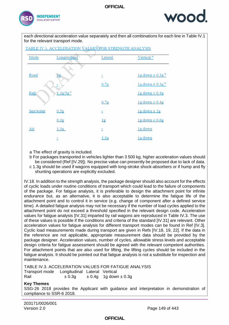
OFFICIAL
203171/0026/001 Version 2.0
Page 149 of 443
OFFICIAL
each directional acceleration value separately and then all combinations for each line in Table IV.1 for the relevant transport mode.
a The effect of gravity is included. b For packages transported in vehicles lighter than 3 500 kg, higher acceleration values should
be considered (Ref [IV.29]). No precise value can presently be proposed due to lack of data. c 1.3g should be used if wagons equipped with long-stroke shock-absorbers or if hump and fly
shunting operations are explicitly excluded. IV.18. In addition to the strength analysis, the package designer should also account for the effects of cyclic loads under routine conditions of transport which could lead to the failure of components of the package. For fatigue analysis, it is preferable to design the attachment point for infinite endurance but, as an alternative, it is also acceptable to determine the fatigue life of the attachment point and to control it in service (e.g. change of component after a defined service time). A detailed fatigue analysis may not be necessary if the number of load cycles applied to the attachment point do not exceed a threshold specified in the relevant design code. Acceleration values for fatigue analysis [IV.31] imparted by rail wagons are reproduced in Table IV.3. The use of these values is possible if the conditions and criteria of the standard [IV.31] are relevant. Other acceleration values for fatigue analysis for different transport modes can be found in Ref [IV.3]. Cyclic load measurements made during transport are given in Refs [IV.18, 19, 22]. If the data in the reference are not applicable, appropriate measurement data should be provided by the package designer. Acceleration values, number of cycles, allowable stress levels and acceptable design criteria for fatigue assessment should be agreed with the relevant competent authorities. For attachment points that are also used for lifting, the lifting cycles should be included in the fatigue analysis. It should be pointed out that fatigue analysis is not a substitute for inspection and maintenance.
TABLE IV.3. ACCELERATION VALUES FOR FATIGUE ANALYSIS Transport mode Longitudinal Lateral Vertical Rail ± 0.3g ± 0.4g 1g down ± 0.3g
Key Themes SSG-26 2018 provides the Applicant with guidance and interpretation in demonstration of compliance to SSR-6 2018.
OFFICIAL
203171/0026/001 Version 2.0
Page 150 of 443
OFFICIAL
6.4 Reviews of Relevant ONR Guidance
Reference: D1
Document Title/Version Number:
ONR. License condition handbook. February 2017
Date of Issue: 2017
Document Review Status: Not known
Document Scope: “This booklet has been produced as an aide-memoire for nuclear inspectors. It reproduces the licence conditions from Schedule 2 of the standard nuclear site licence and highlights the regulatory powers within the conditions.” Summary: The safety of nuclear installations in Great Britain (GB) is assured by a system of regulatory control based on a licensing process by which a corporate body is granted a licence to use a defined site for specified activities. This document describes how the ONR regulates the design, construction and operation of any nuclear installation in GB for which a nuclear site licence is required under the Nuclear Installations Act 1965 (NIA65). Key Requirements: Licence Condition 5: Consignment of nuclear matter 1 The licensee shall not consign nuclear matter (other than excepted matter and radioactive waste) to any place in the United Kingdom other than a relevant site except with the consent of ONR.
2 The licensee shall keep a record of all nuclear matter (including excepted matter and radioactive waste) consigned from the site and such record shall contain particulars of the amount, type and form of such nuclear matter, the manner in which it was packed, the name and address of the person to whom it was consigned and the date when it left the site.
Licence Condition 10: Training 1 The licensee shall make and implement adequate arrangements for suitable training for all those on site who have responsibility for any operations which may affect safety.
3 The licensee shall ensure that once approved no alteration or amendment is made to the approved arrangements unless ONR has approved such alteration or amendment.
Licence Condition 14: Safety documentation 1 Without prejudice to any other requirements of the conditions attached to this licence the licensee shall make and implement adequate arrangements for the production and assessment of safety cases consisting of documentation to justify safety during the design, construction, manufacture, commissioning, operation and decommissioning phases of the installation.
2 The licensee shall submit to ONR for approval such part or parts of the aforesaid arrangements as ONR may specify.
3 The licensee shall ensure that once approved no alteration or amendment is made to the approved arrangements unless ONR has approved such alteration or amendment.
Licence Condition 16: Site plans, designs and specifications 1 The licensee shall submit to ONR an adequate plan of the site (hereinafter referred to as the site plan) showing the location of the boundary of the licensed site and every building or plant on the site which might affect safety.

OFFICIAL
203171/0026/001 Version 2.0
Page 151 of 443
OFFICIAL
3 If any changes are made on the site which affect the said buildings, plant or operations, the licensee shall forthwith send an amended site plan and schedule to ONR incorporating these changes.
Licence Condition 19: Construction or installation of new plant 1 Where the licensee proposes to construct or install any new plant which may affect safety the licensee shall make and implement adequate arrangements to control the construction or installation.
3 The licensee shall ensure that once approved no alteration or amendment is made to the approved arrangements unless ONR has approved such alteration or amendment.
Licence Condition 22: Modification or experiment on existing plant 1 The licensee shall make and implement adequate arrangements to control any modification or experiment carried out on any part of the existing plant or processes which may affect safety.
3 The licensee shall ensure that once approved no alteration or amendment is made to the approved arrangements unless ONR has approved such alteration or amendment.
Licence Condition 23: Operating rules 1 The licensee shall, in respect of any operation that may affect safety, produce an adequate safety case to demonstrate the safety of that operation and to identify the conditions and limits necessary in the interests of safety. Such conditions and limits shall hereinafter be referred to as operating rules.
3 The licensee shall ensure that operations are at all times controlled and carried out in compliance with such operating rules. Where the person appointed by the licensee for the purposes of Condition 26 identifies any matter indicating that the safety of any operation or the safe condition of any plant may be affected that person shall bring that matter to the attention of the licensee forthwith who shall take appropriate action and ensure that the matter is then notified, recorded, investigated and reported in accordance with arrangements made under Condition 7.
5 The licensee shall ensure that once approved no alteration or amendment is made to any approved operating rule unless ONR has approved such alteration or amendment.
Licence Condition 24: Operating instructions
1 The licensee shall ensure that all operations which may affect safety are carried out in accordance with written instructions hereinafter referred to as operating instructions.
2 The licensee shall ensure that such operating instructions include any instructions necessary in the interests of safety and any instructions necessary to ensure that any operating rules are implemented.
3 The licensee shall, if so specified by ONR, furnish to ONR copies of such operating instructions and when any alteration is made to the operating instructions furnished to ONR, the licensee shall ensure that such alteration is furnished to ONR in such time as may be specified.
6 The licensee shall ensure that once approved no alteration or amendment is made to the approved arrangements unless ONR has approved such alteration or amendment.
Licence Condition 25: Operational records 1 The licensee shall ensure that adequate records are made of the operation, inspection and maintenance of any plant which may affect safety.

OFFICIAL
203171/0026/001 Version 2.0
Page 152 of 443
OFFICIAL
2 The aforesaid records shall include records of the amount and location of all radioactive material, including nuclear fuel and radioactive waste, used, processed, stored or accumulated upon the site at any time.
3 The licensee shall record such additional particulars as ONR may specify.
Licence condition 26: Control and supervision of operations The licensee shall ensure that no operations are carried out which may affect safety except under the control and supervision of suitably qualified and experienced persons appointed for that purpose by the licensee.
Licence Condition 28: Examination, inspection, maintenance and testing 1 The licensee shall make and implement adequate arrangements for the regular and systematic examination, inspection, maintenance and testing of all plant which may affect safety.
2 The licensee shall submit to ONR for approval such part or parts of the aforesaid arrangements as ONR may specify.
3 The licensee shall ensure that once approved no alteration or amendment is made to the approved arrangements unless ONR has approved such alteration or amendment.
4 The aforesaid arrangements shall provide for the preparation of a plant maintenance schedule for each plant. The licensee shall submit to ONR for its approval such part or parts of any plant maintenance schedule as ONR may specify.
5 The licensee shall ensure that once approved no alteration or amendment is made to any approved part of any plant maintenance schedule unless ONR has approved such alteration or amendment.
6 The licensee shall ensure in the interests of safety that every examination, inspection, maintenance and test of a plant or any part thereof is carried out.
a) by suitably qualified and experienced persons; b) in accordance with schemes laid down in writing; c) within the intervals specified in the plant maintenance schedule; and d) under the control and supervision of a suitably qualified and experienced person appointed
by the licensee for that purpose.
8 When any examination, inspection, maintenance or test of any part of a plant reveals any matter indicating that the safe operation or safe condition of that plant may be affected, the suitably qualified and experienced person appointed to control or supervise such examination, inspection, maintenance or test shall bring it to the attention of the licensee forthwith who shall take appropriate action and ensure the matter is then notified, recorded, investigated and reported in accordance with arrangements made under Condition 7.
9 The licensee shall ensure that a full and accurate report of every examination, inspection, maintenance or test of any part of a plant indicating the date thereof and signed by the suitably qualified and experienced person appointed by the licensee to control and supervise such examination, inspection, maintenance or test is made to the licensee forthwith upon completion of the said examination, inspection, maintenance or test.
Licence Condition 29: Duty to carry out tests, inspections and examinations 1 The licensee shall carry out such tests, inspections and examinations in connection with any plant (in addition to any carried out under Condition 28 above) as ONR may, after consultation with the licensee, specify.
OFFICIAL
203171/0026/001 Version 2.0
Page 153 of 443
OFFICIAL
2 The licensee shall furnish the results of any tests, inspections and examinations carried out in accordance with paragraph 1 of this condition to ONR as soon as practicable.
Licence Condition 34: Leakage and escape of radioactive material and radioactive waste 1 The licensee shall ensure, so far as is reasonably practicable, that radioactive material and radioactive waste on the site is at all times adequately controlled or contained so that it cannot leak or otherwise escape from such control or containment.
2 Notwithstanding paragraph 1 of this condition the licensee shall ensure, so far as is reasonably practicable, that no such leak or escape of radioactive material or radioactive waste can occur without being detected, and that any such leak or escape is then notified, recorded, investigated and reported in accordance with arrangements made under Condition 7.
Key Themes: A number of ONR License Conditions may be used to regulate the design, inspection, maintenance and use of bolted connections on site.
Throughout the LCs (particularly LC 14, LC 23 & LC 28) is the requirement to maintain of the approved configuration and state of design, including joints through control of design, safety justifications, usage and maintenance. Allowing deviation from the approved configuration would be deemed a breach of LCs. In support of LC 34 it is incumbent on the Licensee to ensure that containment devices are sealed in the manner assumed in the safety justification.
OFFICIAL
203171/0026/001 Version 2.0
Page 154 of 443
OFFICIAL
Reference: D2
Document Title/Version Number: ONR. Safety Assessment Principles for Nuclear Facilities. 2014 Edition Revision 0
Date of Issue: 2014
Document Review Status:-
Document Scope: 1. The SAPs apply to assessments of safety at existing or proposed nuclear facilities. This is usually through our assessment of safety cases in support of regulatory decisions. The term ‘safety case’ is used throughout this document to encompass the totality of the documentation developed by a designer, licensee or duty-holder to demonstrate high standards of nuclear safety and radioactive waste management, and any subset of this documentation that is submitted to the Office for Nuclear Regulation (ONR).
Summary: 2. The principles presented in this document relate only to nuclear safety, radiation protection and radioactive waste management. Conventional hazards associated with a nuclear facility are excluded, except where they have a direct effect on nuclear safety or radioactive waste management. The use of the word ‘safety’ within the document should therefore be interpreted accordingly.
3. The primary purpose of the SAPs is to provide inspectors with a framework for making consistent regulatory judgements on the safety of activities. The principles are supported by Technical Assessment Guides (TAGs), and other guidance, to further assist decision making within the nuclear safety regulatory process (see the ONR website). Although it is not their prime purpose, the SAPs may also provide guidance to designers and duty-holders on the appropriate content of safety cases, clarifying our expectations in this regard.
Key Requirements: See review of Reference D5 “ONR Guide. Integrity of Metal Structures, Systems and Components. Nuclear Safety Technical Assessment Guide NS-TAST-GD-016 Revision 5. March 2017”, which highlights key SAPs clauses pertinent to all matters of structural integrity, of which bolted joints are a subset.
There are no SAPs which specifically apply to the integrity of bolted joints. Key Themes: ECS.3 is pertinent to “Codes and Standards” and states that “Structures, systems and components that are important to safety should be designed, manufactured, constructed, installed, commissioned, quality assured, maintained, tested and inspected to the appropriate codes and standards”.
Clauses 169 to 173 provide further interpretation of the above:
- (169) The codes and standards applied should reflect the functional reliability requirements of the structures, systems and components and be commensurate with their safety classification.
- (170) Codes and standards should be preferably nuclear-specific, leading to a conservative design commensurate with the importance of the safety function(s) being delivered. Each code or standard adopted should be evaluated to determine its applicability, adequacy and sufficiency and should be supplemented or modified as necessary to a level commensurate with the importance of the relevant safety function(s).
- (171) Appropriate nuclear industry-specific, national or international codes and standards should be adopted for Class 1 and 2 structures, systems or components. For Class 3, if there is
OFFICIAL
203171/0026/001 Version 2.0
Page 155 of 443
OFFICIAL
no appropriate nuclear industry-specific code or standard, an appropriate non-nuclear-specific code or standard should be applied instead.
- (172) Where a single item (ie a structure, system or component) needs to deliver multiple safety functions, and these can be demonstrated to be delivered by the item independently of one another, then separate codes and standards should be used appropriate to the parts of the item providing each safety function. Where such independence cannot be demonstrated, codes and standards should be appropriate to the class of the item (ie in accordance with the highest category of safety function to be delivered). Whenever different codes and standards are used for different aspects of the same item, the compatibility between these codes and standards should be demonstrated.
- (173) The combining of different codes and standards for a single aspect of a structure, system or component should be avoided. Where this cannot be avoided, the combining of the codes and standards should be justified and their mutual compatibility demonstrated.
19 ECS.4 is pertinent to the “Absence of established codes and standards” and states “Where there are no appropriate established codes or standards, an approach derived from existing codes or standards for similar equipment, in applications with similar safety significance, should be adopted”.
20 ECS.5 is pertinent to the “Use of experience, tests or analysis” and states that “In the absence of applicable or relevant codes and standards, the results of experience, tests, analysis, or a combination thereof, should be applied to demonstrate that the structure, system or component will perform its safety function(s) to a level commensurate with its classification.”
OFFICIAL
203171/0026/001 Version 2.0
Page 156 of 443
OFFICIAL
Reference: D3
Document Title/Version Number:
ONR Guide. Guidance on the Demonstration of ALARP (As Low As Reasonably Practicable). Nuclear Safety Technical Assessment Guide NS-TAST-GD-005 Revision 9. March 2018
Date of Issue: March 2018
Document Review Status:
This document has been updated to bring in line with ONR’s published guidance on risk informed regulatory decision making and clarify the role of legal precedent in the interpretation of SFAIRP.
Document Scope: 2.1 The purpose of this Technical Assessment Guide (TAG) is to provide advice to ONR inspectors to help them judge whether a licensee has met the requirement to reduce risks to ALARP. As such, the TAG is intended to be used for all ONR regulatory functions relating to nuclear safety falling within the remit of the HSWA.
Summary: 1.1 This Technical Assessment Guide (TAG) represents specific guidance for ONR inspectors on what they should expect of a nuclear licensee or dutyholder1 in meeting its legal requirement to reduce risks so far as is reasonably practicable (SFAIRP). The concept of SFAIRP is normally expressed in terms of reducing risks to “As Low As Reasonably Practicable” (ALARP), the terms SFAIRP and ALARP being synonymous in guidance documents.
Key Requirements: 1.3 The requirement for risks to be ALARP is fundamental and applies to all activities within the scope of the Health and Safety at Work (etc) Act 1974 [HSWA]. It is important that inspectors in whatever role are aware of the need to ensure that licensees meet this requirement where it applies. In simple terms it is a requirement to take all measures to reduce risk where doing so is reasonable. In most cases this is not done through an explicit comparison of costs and benefits, but rather by applying established relevant good practice and standards. The development of relevant good practice and standards includes ALARP considerations so in many cases meeting them is sufficient. In other cases, either where standards and relevant good practice are less evident or not fully applicable, the onus is on the licensee to implement measures to the point where the costs of any additional measures (in terms of money, time or trouble – the sacrifice) would be grossly disproportionate to the further risk reduction that would be achieved (the safety benefit).
3.3 It is important to recognise that not all the legal duties licensees need to meet are qualified by SFAIRP – so ONR’s ALARP guidance should only be applied where this qualification is in place. For example, the duties in various Licence Conditions, which are now applicable provisions of the Energy Act 2013, to make and implement adequate arrangements are not qualified by SFAIRP.
3.4 Nevertheless, the demonstration of ALARP will normally be made within the licensee’s safety case required under Licence Condition 23.
3.9 The HSE ALARP guides published on the Internet (colloquially known as “the ALARP six-pack”) are:
3.10 PRINCIPLES AND GUIDELINES TO ASSIST HSE IN ITS JUDGEMENTS THAT DUTYHOLDERS HAVE REDUCED RISK AS LOW AS REASONABLY PRACTICABLE
This paper defines ALARP and SFAIRP and sets out in plain terms what HSE believes the law requires.
3.11 ASSESSING COMPLIANCE WITH THE LAW IN INDIVIDUAL CASES AND THE USE OF GOOD PRACTICE [4] This paper defines what HSE means by good practice and lists the
OFFICIAL
203171/0026/001 Version 2.0
Page 157 of 443
OFFICIAL
responsibilities of Operating Directorates (which includes ONR) in respect of identifying and maintaining records of good practice.
3.12 POLICY AND GUIDANCE ON REDUCING RISKS AS LOW AS REASONABLY PRACTICABLE IN DESIGN [5]. This paper recognises the importance of taking account of health and safety in design and sets out HSE's intervention policy with respect to design. At licensed sites, intervention in the design is controlled by licence conditions attached under the powers of the NIA, and is a well established process (see T/AST/051 [25] and Nuclear Site Licensees Notes for Applicants [6]). For Authorised Sites, HSWA Section 6 and the Construction, Design and Management Regulations 2007 [CDM] should be used.
3.13 HSE PRINCIPLES FOR COST BENEFIT ANALYSIS IN SUPPORT OF ALARP DECISIONS. This paper explains the uses and limitations of CBA and is particularly concerned with the correct use of CBA as part of ALARP decisions.
3.14 HSE - RISK MANAGEMENT: ALARP AT A GLANCE [8]. This document summarises many of the key terms and concepts.
3.15 HSE - RISK MANAGEMENT: COST BENEFIT ANALYSIS (CBA) CHECKLIST [9]. This document summarises HSE's view of what should and should not be considered in a dutyholder's CBA for health and safety ALARP determinations.
3.16 NIA provides for ONR to attach Licence Conditions to a site licence in the interests of safety and with respect to the handling, treatment, and disposal of nuclear matter. Licence Condition 14 requires arrangements to "produce and assess safety cases .... to justify safety" and Licence Condition 23 requires an adequate safety case be produced and that the facility is then operated in accordance with that safety case.
6.4 In terms of specific sources of relevant good practice for the nuclear industry there are several legal requirements which must be met and in some cases ACoPs (Approved Codes of Practice) and Guidance have been issued (e.g. the ACoPs to the IRRs and on the Management of Health & Safety [13]) to assist the licensee in achieving compliance.
6.5 Standards exist for many engineering and operational features and it is a feature of new designs that licensee proposals may be based on non-UK standards. Such standards should be subject to assessment to ensure they represent appropriate relevant good practice in a UK context. There are also several international bodies which produce standards or guidance documents: where the UK is tied by international agreements, e.g. EU, the standards have the same status as UK ones; where such agreements do not exist, the guidance may be considered as authoritative, but subsidiary to UK requirements. In a nuclear context, IAEA Safety Standards and the Safety Reference Levels developed by WENRA for reactors, decommissioning, and the storage of radioactive waste and spent fuel [21] should be considered to be relevant good practice.
Key Themes: The requirement for risks to be ALARP is fundamental and applies to all activities within the scope of the Health and Safety at Work (etc) Act 1974 [HSWA]. It is important that inspectors in whatever role are aware of the need to ensure that licensees meet this requirement where it applies. In simple terms it is a requirement to take all measures to reduce risk where doing so is reasonable. In most cases this is not done through an explicit comparison of costs and benefits, but rather by applying established relevant good practice and standards.
OFFICIAL
203171/0026/001 Version 2.0
Page 158 of 443
OFFICIAL
Reference: D4
Document Title/Version Number:
ONR Guide. Examination, Inspection, Maintenance and Testing of Items Important to Safety. Nuclear Safety Technical Assessment Guide NS-TAST-GD-009 Revision 5. May 2019
Date of Issue: May 2019
Document Review Status: Last review for correction of typos
Document Scope:
2.1 This TAG directly addresses those ONR SAPs [Ref 1] which relate to in-service and throughout facility life EIMT; EMT.1 to EMT.8. It has been written primarily in general terms so that it applies to all engineering disciplines. It should also be noted that EIMT is considered to be an integral part of the operation of a nuclear facility. Many other TAGs make reference to EIMT but more as an adjunct.
2.2 The SAPs and this TAG address the need to ensure adequate arrangements are (or will be) in place for the EIMT of the safety systems, and safety related SSCs identified in a safety case. These arrangements should address the need to plan, specify, implement, monitor and review the EIMT activities. Additionally where changes are made to either the facility, equipment or the EIMT regime, they do not result in a lowering of the level of nuclear safety defined in the safety case.
Summary: 1. INTRODUCTION 1.1 ONR has established its Safety Assessment Principles (SAPs) which apply to the assessment by ONR specialist inspectors of safety cases for nuclear facilities that may be operated by potential licensees, existing licensees, or other duty-holders. The principles presented in the SAPs are supported by a suite of guides to further assist ONR’s inspectors in their technical assessment work in support of making regulatory judgements and decisions. This Technical Assessment Guide (TAG) is one of these guides.
1.2 Nuclear processes are designed on the premise that the facility and equipment in use will retain the reliability claimed in the facility Safety Case, thus ensuring that the hazard presented by, and the risk associated with the process is kept at an acceptably low level. The reliability of the facility will only be assured through the facility's full lifecycle by a process of maintenance which may include refurbishment or replacement of Structures, Systems and Components (SSCs). This process is based upon a sound understanding of the facility, the identification of SSCs important to safety, knowledge of the equipment's ageing mechanisms and the support of a programme of Examination, Inspection, Maintenance and Testing (EIMT).
Key Requirements: 3. RELATIONSHIP TO LICENCE AND OTHER RELEVANT LEGISLATION
3.1 Site Licence Condition 28: Examination, inspection, maintenance and testing - is of direct relevance to this TAG. LC 28 requires:
1. The licensee shall make and implement adequate arrangements for the regular and systematic examination, inspection, maintenance and testing of all plant which may affect safety.
2. The licensee shall submit to ONR for approval such part or parts of the aforesaid arrangements as ONR may specify.
3. The licensee shall ensure that once approved no alteration or amendment is made to the approved arrangements unless ONR has approved such alteration or amendment.
4. The aforesaid arrangements shall provide for the preparation of a plant maintenance schedule for each plant. The licensee shall submit to ONR for its approval such part or parts of any plant maintenance schedule as ONR may specify.

OFFICIAL
203171/0026/001 Version 2.0
Page 159 of 443
OFFICIAL
5. The licensee shall ensure that once approved no alteration or amendment is made to any approved part of any plant maintenance schedule unless ONR has approved such alteration or amendment.
6. The licensee shall ensure in the interests of safety that every examination, inspection, maintenance and test of a plant or any part thereof is carried out.
a) by suitably qualified and experienced persons; b) in accordance with schemes laid down in writing; c) within the intervals specified in the plant maintenance schedule; and d) under the control and supervision of a suitably qualified and experienced person appointed
by the licensee for that purpose.
7. Notwithstanding the above paragraphs of this condition ONR may agree to an extension of any interval specified in the plant maintenance schedule.
8. When any examination, inspection, maintenance or test of any part of a plant reveals any matter indicating that the safe operation or safe condition of that plant may be affected, the suitably qualified and experienced person appointed to control or supervise such examination, inspection, maintenance or test shall bring it to the attention of the licensee forthwith who shall take appropriate action and ensure the matter is then notified, recorded, investigated and reported in accordance with arrangements made under Condition 7.
9. The licensee shall ensure that a full and accurate report of every examination, inspection, maintenance or test of any part of a plant indicating the date thereof and signed by the suitably qualified and experienced person appointed by the licensee to control and supervise such examination, inspection, maintenance or test is made to the licensee forthwith upon completion of the said examination, inspection, maintenance or test.
5.1 Fundamentals 5.1.1 EIMT requirements, including specification of what is to be done and its periodicity should be identified in the safety case, taking account of any reliability claims.
5.1.2 There should be traceability of EIMT requirements from the safety case through the Plant Maintenance Schedule to Maintenance Instructions.
4. RELATIONSHIP TO SAPS, WENRA REFERENCE LEVELS AND IAEA SAFETY STANDARDS ADDRESSED 4.1 The SAPs (2014 Edition Revision 0) directly addressed by this TAG are:
4.1.1 EMT.1 to EMT.8 in the section of the 2014 SAPs entitled Maintenance, inspection and testing.
4.1.2 The Key Engineering Principle EKP.3 ‘Defence in Depth’ states that “Nuclear facilities should be designed and operated so that defence in depth against potentially significant faults or failures is achieved by the provision of multiple independent barriers to fault progression”. Table 1 of the SAPs identifies the first level as ‘prevention of abnormal operation and failures by design’ with maintenance identified as one of the essential means of achievement.
4.1.4 There are a number of other SAPs that are relevant to the assessment of EIMT. The list below provides guidance on these in the listing order of the 2014 Edition of the SAPs:
MS.2: Capable organisation
SC.2: Safety case process outputs
SC.4: Safety case characteristics
SC.6: Safety case content and implementation
SC.7: Safety case maintenance
EQU.1: Qualification procedures
ERL.2: Measures to achieve reliability
EAD.2: Lifetime margins
OFFICIAL
203171/0026/001 Version 2.0
Page 160 of 443
OFFICIAL
ELO.1: Access
EMC.22: Material compatibility
EES.4: Sharing with other facilities 4.2 WENRA Reference Levels (RLs) and IAEA Safety Standards and Guide
4.2.1 The update of this TAG considers the Western European Nuclear Regulators’ Association [Ref 2] (WENRA) and International Atomic Energy Agency [Ref 4 to 9] (IAEA) publications for specific applicability. It should be noted that the SAPs are intended for both existing and new facilities whereas the WENRA Reactor Safety Reference Levels are intended for existing reactors. However there is little difference between the general requirements of each. The WENRA and IAEA documents considered in this TAG are focused on nuclear reactor power
plants and so do not have the same broad scope intent of the SAPs and this TAG. Section 4 of NS-TAST-GD-005 identifies the WENRA RLs as Relevant Good Practice for existing civil nuclear reactors
4.2.2 WENRA Reference Level Issue K is dedicated to EIMT with the following worthy of note during assessment of Licensees’ EIMT arrangements:
the need for the preparation and implementation of documented programmes of EIMT of SSCs important to safety to ensure that their availability, reliability, and functionality remains in accordance with the design over the lifetime of the plant;
the programmes should include periodic inspections and tests of SSCs important to safety in order to determine whether they are acceptable for continued safe operation of the plant or whether any remedial measures are necessary;
the extent and frequency of preventative EIMT should be determined using a systematic approach;
the impact of maintenance on plant safety is to be assessed using data from plant EIMT;
SSCs important to safety are to be designed with ease of EIMT to demonstrate integrity and functional capability over the plant lifetime;
proven alternative approaches may be specified and other safety precautions taken to compensate for the potential for undiscovered failures where EIMT provisions are not attainable; and
the need for configuration control to permit plant to be removed from service before testing and then for return to service.
4.2.4 The following IAEA Safety Standards and Guides make reference to the need for EIMT as a means of gaining assurance that the design intent is maintained in all disciplines of nuclear engineering and safety assurance. Appendix 2 provides further details from the IAEA publications in so far as they address EIMT and how it is an integral part of the design and operation of nuclear power plant:
SSR-2/1 Safety of Nuclear Power Plants: Design
NS-G-2.6: Maintenance, Surveillance and In-Service Inspection in Nuclear Power Plant;
INSAG 19:Maintaining the Design Integrity of Nuclear Installations throughout their Operating Life;
INSAG 14: Safe Management of the Operating Lifetime of Nuclear Power Plants. APPENDIX 2: IAEA SAFETY STANDARDS AND GUIDES A2.1 Design Within the Safety Standards Series the IAEA has produced a Safety Guide “Safety of Nuclear Power Plants Design” SSR-2/1…There will be formal arrangements for the Design Authority to retain the services of the design organisations to maintain assurance of design intent after this move. This design process is complemented by a comprehensive safety analysis process, running in parallel, which is also under the responsibility of the designated entity. The SSR-2/1 document
OFFICIAL
203171/0026/001 Version 2.0
Page 161 of 443
OFFICIAL
has many sections dealing with the need for use of EIMT to gain assurance that design intent is met in all disciplines of nuclear engineering, and in safety assurance.
A2.2 Maintenance, Surveillance, and In Service Inspection - The IAEA has also produced a Safety Guide on “Maintenance, Surveillance and In-Service Inspection in Nuclear Power Plant” NS-G-2.6 [Ref 5]. This document again covers the need for a systematic approach for evaluation of the safety importance of SSCs to determine the necessary maintenance, surveillance and in service inspection activities, suggesting a proactive, reliability centered approach. This systematic approach is to be performed in such a manner that it establishes which maintenance tasks are to be performed and at what periodicity.
A2.3 Maintaining the Design Integrity of Nuclear Installations throughout their Operating Life - In the IAEA International Nuclear Safety Advisory Group series of reports, Report INSAG 19 discusses the problem of maintaining the design integrity of a nuclear power plant over its entire lifetime and also offers some solutions. Although the technical offices of the operating organisation will be the entity with an overview of the whole plant design (the Design Authority lead), it may assign some responsibility for design integrity of defined parts of the plant to “responsible designers”, whilst retaining Intelligent Customer status. This combination of formally designated parts of the operating organisation’s technical offices and contracted responsible designers is the Design Authority mentioned in IAEA Safety Documents.
Consultation with the Design Authority becomes important when determining the adequacy of results from EIMT and agreeing to design or EIMT changes that may be needed as a result of such activities. A2.4 Safe Management of the Operating Lifetime of Nuclear Power Plants - In the IAEA International Nuclear Safety Advisory Group series of reports, INSAG 14 is a further report that suggests general safety objectives for safe management of the operating lifetime of nuclear power plant, reflecting on the ageing processes that can degrade the integrity of structures and components over time.
In paragraph 15 of the report it states that: “There is an essential linkage between the operating lifetime of a nuclear power plant, which depends on the evaluation of age related degradation effects and on the determination of the capability to manage those effects, and the surveillance, monitoring, inspection, testing and engineering evaluation activities.”
“It requires a comprehensive assessment of all of the relevant factors, including the periodicity of the programmes, the rigor of acceptance criteria, the extent of corrective actions and the exposure of personnel. This assessment ensures that the management of ageing effects through operation and maintenance strategies guarantees that the safety functions of the structures systems and components will continue to be performed.” Key Themes: All applicable clauses are key to on-site activities.
OFFICIAL
203171/0026/001 Version 2.0
Page 162 of 443
OFFICIAL
Reference: D5
Document Title/Version Number:
ONR Guide. Integrity of Metal Structures, Systems and Components. Nuclear Safety Technical Assessment Guide NS-TAST-GD-016 Revision 5. March 2017
Date of Issue: March 2017
Document Review Status:
Revision 5 — Revisions on technical qualification and update
Document Scope:
This TAG provides ONR inspectors with additional guidance and interpretation of SAPs EMC.1 to EMC.34 which are concerned with the integrity of metal structures, systems and components (SSCs). These SAPs cover process-containing SSCs such as pressure vessels, storage tanks, pipes and valves.
Summary: 1.1. ONR has established its Safety Assessment Principles (SAPs) which apply to the assessment by ONR specialist inspectors of safety cases for nuclear facilities that may be operated by potential licensees, existing licensees, or other duty-holders. The principles presented in the SAPs are supported by a suite of guides to assist ONR’s inspectors in their technical assessment work to support the making of regulatory judgments and decisions. This technical assessment guide (TAG) is one of these guides.
1.2. The TAG (Revision 5) is revised and updated; in particular, to give:
Advice on: o The international response to the Fukushima nuclear accident (Appendix A1). o Inhomogeneities in steels and technical qualification in (§5.29 & §5.30) and (Appendix A3)
Updated guidance on: o The purpose of assessment and safety categorization and classification (§5.3) o The manufacture of highest reliability components and structures (§5.56 to §5.64) o Lifetime records (§5.70) o Operational experience (§5.100 to §5.103).
Key Requirements: 3.1. The primary licence conditions (LCs) for which assessments of metal SSCs are to be carried out are:
LC 14 (Safety documentation)
LC 15 (Periodic review)
LC 17 (Management systems)
LC 19 (Construction or installation of new plant)
LC 20 (Modification to design of plant under construction)
LC 21 (Commissioning)
LC 22 (Modification or experiment on existing plant)
LC 23 (Operating rules)
LC 24 (Operating instructions)
LC 25 (Operational records)
LC 26 (Control and supervision of operations)
LC 27 (Safety mechanisms, devices and circuits)
LC 28 (Examination, inspection, maintenance and testing)
LC 29 (Duty to carry out tests, inspections and examinations)
LC 30 (Periodic shutdown)
LC 34 (Leakage and escape of radioactive material and radioactive waste)
LC 35 (Decommissioning)
OFFICIAL
203171/0026/001 Version 2.0
Page 163 of 443
OFFICIAL
SAPs 4.1. The ONR SAPs for the integrity of metal SSCs are EMC.1 to EMC.34 (paragraphs 280 to 319) which are closely related to those for ageing and degradation: EAD.1 to EAD.5 (paragraphs 212 to 221). These SAPs—in the sequence adopted by [1]—are:
Integrity of metal SSCs Highest reliability structures or components
o EMC.1 (Safety case and assessment) o EMC.2 (Use of scientific and technical issues) o EMC.3 (Evidence)
General o EMC.4 (Procedural control) o EMC.5 (Freedom from and tolerance of defects) o EMC.6 (Means to identify defects)
Design o EMC.7 (Loadings) o EMC.8 (Providing for examination) o EMC.9 (Product form) o EMC.10 (Weld positions) o EMC.11 (Failure modes) o EMC.12 (Brittle behaviour)
Manufacture and installation o EMC.13 (Materials) o EMC.14 (Techniques and procedures) o EMC.15 (Control of materials) o EMC.16 (Contamination) o EMC.18 (Third-party inspection) o EMC.19 (Non-conformances) o EMC.20 (records)
Manufacturing, pre-service and in-service examination and testing o EMC.27 (Examination) o EMC.28 (Margins) o EMC.29 (Redundancy and diversity) o EMC.30 (Qualification)
Operation o EMC.21 (Safe operating envelope) o EMC.22 (Material compatibility) o EMC.23 (Ductile behaviour)
Monitoring o EMC.24 (Operation) o EMC.25 (Leakage) o EMC.26 (Forewarning of failure)
In-service repairs and modifications o EMC.31 (Repairs and modifications)
Analysis o EMC.32 (Stress analysis) o EMC.33 (Use of data) o EMC.34 (Defect sizes)
Ageing and degradation
EAD.1 (Safe working life)
EAD.2 (Lifetime margins)
EAD.3 (Periodic measurement of material properties)

OFFICIAL
203171/0026/001 Version 2.0
Page 164 of 443
OFFICIAL
EAD.4 (Periodic measurement of parameters)
EAD.5 (Obsolescence) Structural integrity philosophy 5.10. The starting point for design is compliance with relevant national and international codes and standards. In addition, depending on the nuclear safety significance (§5.3), safety case claims for the structural integrity of SSCs may require further substantiation.
5.12. For structures and components classified as highest reliability, the inspector should invoke principles EMC.1, EMC.2 and EMC.3 to reflect the radiological consequences of failure. EMC. 1 addresses two particularly important aspects:
The SSC should be as defect free as possible
It should be demonstrated to be defect tolerant.
5.13. EMC.2 calls for the assessment to include a comprehensive examination of relevant scientific and technical issues and to take account of available precedent.
5.14. To achieve these fundamental requirements, several related and independent arguments should be used, based on the following (see EMC.3 - many of the following contribute to the defect tolerance of SSCs or the management of aspects that affect defect tolerance):
(a) The use of sound design concepts and proven design features (b) A detailed design loading specification covering normal operation, plant transients, faults,
internal and external hazards (c) Consideration of potential in-service degradation mechanisms (d) Analysis of the potential failure modes for all conditions arising from design specification
loadings (e) Use of proven materials (f) Application of high standards of manufacture, including manufacturing inspection and
examination (g) High standards of quality assurance throughout all stages of design, procurement,
manufacture, installation and operation (h) Pre-service and in-service examination to detect and characterize defects at a stage before
they could develop to cause gross failure (i) Defined limits of operation to ensure the facility is operated within the limits of the safety
case. Where appropriate, limits of operation should be supported by protection systems, for instance overpressure protection
(j) In-service monitoring of facility operational parameters (k) In-service materials monitoring schemes (l) A process for review of facility operation to ensure the facility is operated and materials
performance is within the assumptions of the safety case (m) A process for review of and response to deviations (n) A process for review of experience from other facilities, developments in design and analysis
methodologies and the understanding of degradation mechanisms for applicability to the component or structure in question
(o) A process for control of in-service repairs or modifications to similar codes, specifications and standards as for original manufacture, taking account of developments since manufacture.
Highest reliability SSCs: Discounting gross failure 5.17. In some cases, a licensee may propose a safety case where the likelihood of gross structural failure is claimed to be so low that it may be discounted; even so, if failure did occur, the consequences would be unacceptable. Licensees invoke such lines of argument where the consequences are unacceptable or where it would be difficult to demonstrate that consequences are acceptable. One reason for unacceptable consequences is often that there is no means of mitigating the effects of the structural failure.
OFFICIAL
203171/0026/001 Version 2.0
Page 165 of 443
OFFICIAL
….Discounting gross failure should only be invoked if the consequences of failure are unacceptable, or it is not Report NS-TAST-GD-016 Revision 5 TRIM 2015/423015 Page 10 of 42 possible to demonstrate that the consequences are acceptable. SAPs paragraphs 287 to 291 discuss such safety cases. The content of the SAPs will not be repeated here. However the following are emphasized:
'…a claim that gross failure of a pressure vessel may be discounted cannot be plausibly associated with a failure rate much better than 1 × 10⁻⁷ to 1 × 10⁻⁸ per vessel year…' '…claims for pipework weld failure rates for gross failure (e.g. guillotine failure) much better than 1 × 10⁻⁸ to 1 × 10⁻⁹ per weld year should not be considered plausible…'
Design - The use of sound design concepts and proven design features 5.26. To demonstrate that structures meet their safety functional requirements, it is necessary to establish that sound design concepts, rules, standards, methodologies and proven design features have been used, and that the design is robust. Guidance on safety classification, codes and standards is provided in ECS.1 to ECS.5, paragraphs 158 to 179, paragraphs 172 to 173, paragraph 191 and EAD.2. The requirements depend on the safety categorisation of the structure.
5.27. All loadings for operation, credible faults and tests should be identified and the magnitudes specified (EMC.7, EMC.11). Load combinations should be defined. SAPs EHA.1, EHA.3 to EHA.5 and EHA.7 cover external and internal hazard loads. Load definitions should be conservative, and remain appropriate for the future operation of the structure.
5.28. For pressure boundary and other load bearing structures, the use of appropriate British Standards, or International Standards might well be acceptable as a minimum. However where codes are perceived not to reflect modern requirements or practices, it may be worthwhile and practicable to invoke additional stress analysis and analysis of fabrication processes, inspections or materials. Most design codes express limits in term of stress. However, for non-pressure boundary structures e.g. core support structures, functional limits on displacement may be important.
5.32. The design should take due account of degradation processes, including irradiation embrittlement, corrosion, erosion, creep, fatigue and ageing, and for the effects of the chemical and physical environment. The potential for interaction effects should also be considered, e.g. creep/fatigue and stress corrosion cracking.
Load analysis - The analysis of all conditions within the design basis 5.36. The safety case should include an analysis of the potential failure modes for all conditions arising from design basis loads. It may also be appropriate to consider the resilience of structures or components to beyond design basis events.
5.40. The complexity of the analysis will be dependent on the safety categorisation of the SSC. For the highest category, this might include finite element stress analysis and, where failure by crack growth is concerned, a fracture mechanics assessment in accordance with recognized procedures such as R5 [8], R6 [9] or BS 7910 [10]. It is important that the inspector ensures that analysis codes and procedures are adequately verified and validated for the particular application as required by EMC.32, EMC.34 and SAPs paragraph 316. For lower category structures, compliance with appropriate national and international standards may be sufficient.
Materials: The use of proven materials 5.53. It is important to verify that safety significant SSCs are constructed from materials with well-established properties and behaviour, EMC.13. The potential degradation mechanisms that could occur should be established at the design stage and appropriate materials chosen.
Manufacture, inspection and testing
OFFICIAL
203171/0026/001 Version 2.0
Page 166 of 443
OFFICIAL
5.56. Metallurgical and other manufacturing processes, including in-process inspections, should be subject to procedural control to ensure that high standards are achieved (EMC.4). Other relevant SAPs are
EMC.14—Manufacture and installation should use proven techniques and approved procedures to minimize the occurrence of defects that might affect the integrity of components or structures.
EMC.15—Materials identification, storage and issue should be closely controlled
EMC.16—The potential for contamination of materials during manufacture and installation should be controlled to ensure the integrity of components and structures is not compromised
5.57. The material specification, manufacturing processes and inspections should be suitable and should ensure that the SSC is free from significant defects and tolerant of any remaining defects (ECS.3 with paragraph 169 and EMC.5, EMC.6). SSCs should be designed and fabricated to facilitate examination during manufacture and service (e.g. the selection of forged rather than cast austenitic stainless steel components, to aid the transmission of ultrasound and the control of metallurgical processes to control grain size) (EMC.8 and EMC.9).
5.59. The starting point for metallic SSCs important to nuclear safety is compliance with the relevant design codes and specifications. For highest reliability SSCs for which the likelihood of gross failure is discounted, see §5.17 to §5.22, there is an expectation that further measures are put in place so that:
All risks to achieving an adequate level of quality are identified and controlled
There is evidence that each component is of adequate quality throughout its entire volume
There is evidence that component quality is repeatable and consistent between serial components.
Quality assurance (QA) 5.65. There should be appropriate quality assurance throughout all stages of design, procurement, manufacture, installation, commissioning, operation and decommissioning; see EQU.1. Quality assurance arrangements are also required for production of the safety case.
Inspection: Pre-service and in-service examination and in-service monitoring 5.72. Examination immediately prior to and during service and in-service monitoring have three objectives:
To confirm the plant is in the configuration assumed in the safety case
To confirm any predicted degradation or aging effect is developing within the rate allowed for in the safety case
To confirm there is no manufacturing shortfall or degradation during storage, outages or service that is not dealt with in the safety case.
Manufacture and installation should be subject to appropriate third-party independent inspection to confirm that processes and procedures are being followed (EMC.18).
5.75. In-service examinations should be carried out where they are reasonably practicable to enable the present condition of the structure to be confirmed, and to verify that the SSC is behaving as the safety case assumes. In-service examination provides a means of assuring that SSCs remain at all times fit for purpose (EMC.27, EMC.28).
5.76. For high integrity SSCs the examination procedures should be redundant and diverse, e.g. radiography, ultrasonics, and aided surface examinations (such as liquid penetrant or magnetic particle); and possibly redundant and diverse within one method e.g. ultrasonics (EMC.29 and EMC.30). Where appropriate, repeat examinations should be carried out by different examination teams. The adequacy of examination procedures and personnel should be qualified. The interpretation of examination results and the assessment of their structural integrity significance should be carried out by suitably qualified and experienced personnel. For crack-like defects, the defect sizes and orientation used in integrity analyses should be pessimistic and include the
OFFICIAL
203171/0026/001 Version 2.0
Page 167 of 443
OFFICIAL
contribution associated with the uncertainties in defect location and sizing for the particular examination technique.
5.77. The extent and periodicity of the examination proposals should be commensurate with the operational duty and safety functional requirement (EMT.6 and paragraph 209). Where defects, degradation or deviations from design intent are found in existing SSCs any proposed remedial action or technical justification should be assessed via the licensee's plant modification procedure, including Independent Nuclear Safety Assessment.
Ageing and degradation 5.93. In preceding sections of this TAG, aspects of ageing and degradation have been implicitly considered. For metal SSCs, the consideration of ageing and degradation at the design stage and during service is long established practice. Mechanisms such as creep, fatigue, thermal strain ageing, irradiation embrittlement, environmental effects such as corrosion and flow assisted corrosion, are well recognized and routinely considered in structural integrity evaluations.
5.95. The safety case for nuclear facility SSCs needs to include a suitably conservative consideration of the effects of ageing and degradation on safety margins throughout plant life, including decommissioning.
Key Themes: The majority of SAPS applicable to structural integrity apply to bolted joints. There is no specific advice for the integrity of bolted joints and this may be an omission under the EMC SAPs. In light of the statement (see Ref E1 “IAEA. Assessment and Management of Ageing of Major Nuclear Power Plant Components Important to Safety: PWR Pressure Vessels 2007 Update. IAEA-TECDOC-1556” that the most susceptible components to fatigue are closure bolts, and the inclusion of some advice for welds in EMC.10, then bolted joints which are critical to safety might warrant some specific advice.
OFFICIAL
203171/0026/001 Version 2.0
Page 168 of 443
OFFICIAL
Reference: D6
Document Title/Version Number:
ONR Guide. The Purpose, Scope and Content of Safety Cases. Nuclear Safety Technical Assessment Guide NS-TAST-GD-051 Revision 4. June 16
Date of Issue: 2016
Document Review Status:
Due July 2019
Document Scope:
2. PURPOSE AND SCOPE 2.1 The purpose of this document is to provide ONR inspectors with broad guidance on safety cases. The guide sets out the purpose of nuclear safety cases and expectations on how they are used, their overall qualities, how they may be structured and what information they should contain.
2.2 Guidance is also provided on common problems with safety cases based on ONR’s experience (Appendix 1). Safety case shortcomings identified in the Nimrod Review are set out in Appendix 2.
2.3 The scope covers safety cases for the different phases in the life cycle of facilities, e.g. design, construction, commissioning, operation, decommissioning. Guidance is given to inspectors on the issues that should be addressed in safety cases for the different phases of operation.
Summary: 1. INTRODUCTION 1.1 This technical assessment guide is guidance to ONR inspectors on the purpose, scope and content of safety cases.
1.2 The previous update brought in developments in ONR thinking, particularly following the Haddon-Cave report into the Nimrod crash [1]. This revision is another evolutionary update with changes made to ensure full compatibility with the 2014 major revision of the Safety Assessment Principles [2].
Key Requirements: 3. RELATIONSHIP TO LICENCE AND OTHER RELEVANT LEGISLATION LICENCE 3.1 The regulatory basis for this guide encompasses a number of licence conditions. LC23 (Operating Rules), specifically 23(1), requires a licensee to produce an adequate safety case in respect of any operation that may affect safety. LC19 (Construction or Installation of New Facility), LC20 (Modification to Design of Facility under Construction), LC21 (Commissioning), LC22 (Modification or Experiment on Existing Facility) and LC35 Decommissioning) all require ‘adequate documentation to justify safety’ within the context of the specific condition. LC14 (Safety Documentation) and LC15 (Periodic Review) require a licensee to make and implement adequate arrangements for the production of safety cases and for the periodic review and reassessment of safety cases, respectively.
OTHER RELEVANT LEGISLATION
3.3 In addition to the nuclear licence condition requirements, safety documentation may be required under other legislation (e.g. IRR 1999, REPPIR 2001, MHSAW 1999) or to meet the requirements of other regulators (e.g. EA, SEPA).
3.4 Sections 2 and 3 of the HSW Act 1974 require the employer to reduce the risks to employees and other persons, so far as is reasonably practicable. In judging whether licensees have complied with their legal duties ONR makes use of the risk management procedures explained (for example) in Reducing Risks, Protecting People document. The fundamental requirement is that the safety
OFFICIAL
203171/0026/001 Version 2.0
Page 169 of 443
OFFICIAL
case should demonstrate how risks are reduced to levels that are As Low As Reasonably Practicable (ALARP).
4. RELATIONSHIP TO SAPS, WENRA REFERENCE LEVELS AND IAEA SAFETY STANDARDS ADDRESSED
SAPS 4.1 The Safety Assessment Principles for Nuclear Facilities (SAPs) [2] provide a framework to guide regulatory decision-making in the nuclear permissioning process. The SAPs include a section on the Regulatory Assessment of Safety Cases (paras 79–113 of [2]) with principles SC.1 – SC.8. These principles encompass: safety case processes (SC.1 and SC.2); safety case characteristics (SC.3 to SC.6); and safety case management (SC.7 and SC.8). As identified in the Application of the SAPs Section and The Regulatory Assessment of Safety Cases Section of the SAPs, during safety case assessment inspectors should use the principles proportionately commensurate with the radiological hazards presented.
ADVICE TO INSPECTORS
5. DEFINITION OF A NUCLEAR SAFETY CASE 5.1 The guidance in the SAPs identified that ‘A safety case is a logical and hierarchical set of documents that describes risk in terms of the hazards presented by the facility, site and the modes of operation, including potential faults and accidents, and those reasonably practicable measures that need to be implemented to prevent or minimise harm. It takes account of experience from the past, is written in the present, and sets expectations and guidance for the processes that should operate in the future if the hazards are to be controlled successfully.
5.2 The term ‘nuclear safety case’ may relate to a site, a facility, part of a facility, a modification to a facility or to the operations within a facility, or to one or more significant issues.
6. THE PURPOSE OF A SAFETY CASE
6.3 In particular, the purpose of a safety case is described in para 101 of the SAPs[2]: To achieve these, a safety case should:
(a) identify the facility’s hazards by a thorough and systematic process; (b) identify the failure modes of the plant or equipment by a thorough and systematic fault and
fault sequence identification process; (c) demonstrate that the facility conforms to relevant good engineering practice and sound
safety principles. (For example, a nuclear facility should be designed against a set of deterministic engineering rules, such as design codes and standards, using the concept of ‘defence in depth’1 and with adequate safety margins.) Instances where good practice has not been met should be identified and a demonstration provided to justify why these are considered to grossly disproportionate;
(d) provide sufficient information to demonstrate that engineering rules have been applied in an appropriate manner. (For example, it should be clearly demonstrated that all structures, systems and components have been designed, constructed, commissioned, operated and maintained in such a way as to enable them to fulfil their safety functions for their projected lifetimes.);
(e) analyse normal operations and show that resultant doses of ionising radiation, to both members of the workforce and the public are, and will continue to be, within regulatory limits and ALARP;
(f) analyse identified faults and severe accidents, using complementary fault analysis methods to demonstrate that risks are ALARP;
(g) demonstrate that radioactive waste management and decommissioning have been addressed in an appropriate manner; and
(h) provide the basis for the safe management of people, plant and processes. (For example, the safety case should address management and staffing levels, training requirements,
OFFICIAL
203171/0026/001 Version 2.0
Page 170 of 443
OFFICIAL
maintenance requirements, operating and maintenance instructions, and contingency and emergency instructions).
7. OVERALL QUALITIES OF A SAFETY CASE
7.1 Intelligible The safety case should be intelligible and structured logically to meet the needs of those who will use it (e.g. operators, maintenance staff, technical staff, managers accountable for safety).
7.2 Valid
7.3 Complete
7.4 Evidential
7.5 Robust A safety case should demonstrate that the nuclear facility will or does conform to good nuclear engineering practice and sound safety principles, including defence-in-depth and adequate safety margins.
7.6 Integrated
7.7 Balanced In the words of Lord Cullen at the Ladbroke Grove Rail Inquiry, safety cases should “encourage people to think as actively as they can to reduce risks.” Therefore:
A safety case should present a balanced account, taking into consideration the level of knowledge and understanding.
Areas of uncertainty should be identified, not just strengths and claimed conservatism.
9. THE SAFETY CASE IN CONTEXT 9.1 It should always be remembered that the documented safety case is not an end in itself. It forms an important part of how the licensee manages safety. The requirements of the safety case need to be implemented and managed effectively to deliver safety.
The licensee must ensure continually that the safety case is consistent with the as-built facility and that the facility is operated and maintained in accordance with safety case requirements and assumptions. The licensee must have effective processes to ensure these objectives are achieved.
9.2 Fundamental to the safety case are the principles, standards and criteria which the licensee intends to maintain. These must, as a minimum, meet statutory requirements and in particular, show that risks to individuals will be acceptably low and ALARP.
They will include design standards, safety criteria and general standards of safety management. They should be mutually consistent and their selective use should be avoided. It is important that the licensee’s standards and criteria do not conflict with any statutory duties and requirements.
Key Themes: NS-TAST-GD-051 Revision 4 states that “Fundamental to the safety case are the principles, standards and criteria which the licensee intends to maintain. These must, as a minimum, meet statutory requirements and in particular, show that risks to individuals will be acceptably low and ALARP”
It is a key requirement of UK ALARP to adopt RGP wherever appropriate (which would include the design and execution of bolted joints) and NS-TAST-GD-051 Revision 4 highlights the requirement for all safety cases to “demonstrate that the facility conforms to relevant good engineering practice and sound safety principles. (For example, a nuclear facility should be designed against a set of deterministic engineering rules, such as design codes and standards, using the concept of ‘defence in depth’1 and with adequate safety margins.)”
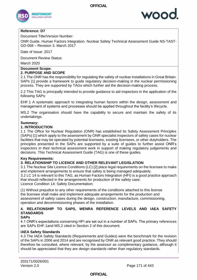
OFFICIAL
203171/0026/001 Version 2.0
Page 171 of 443
OFFICIAL
Reference: D7
Document Title/Version Number:
ONR Guide. Human Factors Integration. Nuclear Safety Technical Assessment Guide NS-TAST-GD-058 – Revision 3. March 2017
Date of Issue: 2017
Document Review Status:
March 2020
Document Scope: 2. PURPOSE AND SCOPE 2.1 The ONR has the responsibility for regulating the safety of nuclear installations in Great Britain. SAPs [1] provide a framework to guide regulatory decision-making in the nuclear permissioning process. They are supported by TAGs which further aid the decision-making process.
2.2 This TAG is principally intended to provide guidance to aid inspectors in the application of the following SAPs:
EHF.1 A systematic approach to integrating human factors within the design, assessment and management of systems and processes should be applied throughout the facility’s lifecycle.
MS.2 The organisation should have the capability to secure and maintain the safety of its undertakings.
Summary: 1. INTRODUCTION 1.1 The Office for Nuclear Regulation (ONR) has established its Safety Assessment Principles (SAPs) [1] which apply to the assessment by ONR specialist inspectors of safety cases for nuclear facilities that may be operated by potential licensees, existing licensees, or other dutyholders. The principles presented in the SAPs are supported by a suite of guides to further assist ONR’s inspectors in their technical assessment work in support of making regulatory judgements and decisions. This Technical Assessment Guide (TAG) is one of these guides.
Key Requirements: 3. RELATIONSHIP TO LICENCE AND OTHER RELEVANT LEGISLATION 3.1 The Nuclear Site Licence Conditions (LC) [2] place legal requirements on the licensee to make and implement arrangements to ensure that safety is being managed adequately. 3.2 LC 14 is relevant to this TAG, as Human Factors Integration (HFI) is a good practice approach that should reflected in the arrangements for production of the safety case: Licence Condition 14: Safety Documentation:
(1) Without prejudice to any other requirements of the conditions attached to this license the licensee shall make and implement adequate arrangements for the production and assessment of safety cases during the design, construction, manufacture, commissioning, operation and decommissioning phases of the installation.
4. RELATIONSHIP TO SAPS, WENRA REFERENCE LEVELS AND IAEA SAFETY STANDARDS SAPs 4.1 ONR’s expectations concerning HFI are set out in a number of SAPs. The primary references are SAPs EHF.1and MS.2 cited in Section 2 of this document.
IAEA Safety Standards 4.3 The IAEA Safety Standards (Requirements and Guides) were the benchmark for the revision of the SAPs in 2006 and 2014 and are recognised by ONR as relevant good practice. They should therefore be consulted, where relevant, by the assessor as complimentary guidance, although it should be appreciated that they are design standards rather than regulatory standards.

OFFICIAL
203171/0026/001 Version 2.0
Page 172 of 443
OFFICIAL
IAEA Safety Standards 4.3 The IAEA Safety Standards (Requirements and Guides) were the benchmark for the revision of the SAPs in 2006 and 2014 and are recognised by ONR as relevant good practice. They should therefore be consulted, where relevant, by the assessor as complimentary guidance, although it should be appreciated that they are design standards rather than regulatory standards. Other International Standards The following International Standards are also relevant:
BS EN ISO 6385:2016 Ergonomic Principles in the Design of Work Systems
BS EN ISO 11064 Ergonomic Design of Control Centres Parts 1-7
BS EN ISO 9241 – 210:2010 Ergonomics of Human-System Interaction. Humancentred design for interactive systems
ISO/TR 18529:2000 Ergonomics of Human-System Interaction – Human-centred lifecycle process descriptions
5. ADVICE TO ASSESSORS Human Factors Integration 5.1 HFI is a good practice approach to the application of Human Factors (HF) to systems development. As a methodology it provides an organising framework to help ensure that all relevant HF issues are identified and addressed. In addition the HFI approach has a management strategy that aims for timely and appropriate integration of HF activities throughout the project.
5.5 In recent years the term ‘human performance’ has evolved, and in some areas of the UK nuclear industry this term has been misinterpreted to mean something different than the widely recognised term ‘human factors’ or ‘human and organisational factors’.
5.7 For clarity, ONR recognises and supports the Institute of Nuclear Power Operators (INPO) ‘definition’ of human performance – the avoidance of human error. Similarly the Organisation for Economic Co-operation and Development’s (OECD) working group on risk and special experts group on human and organisational factors note that “…….the factors influencing human performance are known as human and organisational factors….(and)…human factors are task, individual and organisational characteristics influencing human performance”, i.e. the terms are largely synonymous and have the same aims.
Key Themes: NS-TAST-GD-058 – Revision 3 is an ONR guide for Human Factor Methodologies.
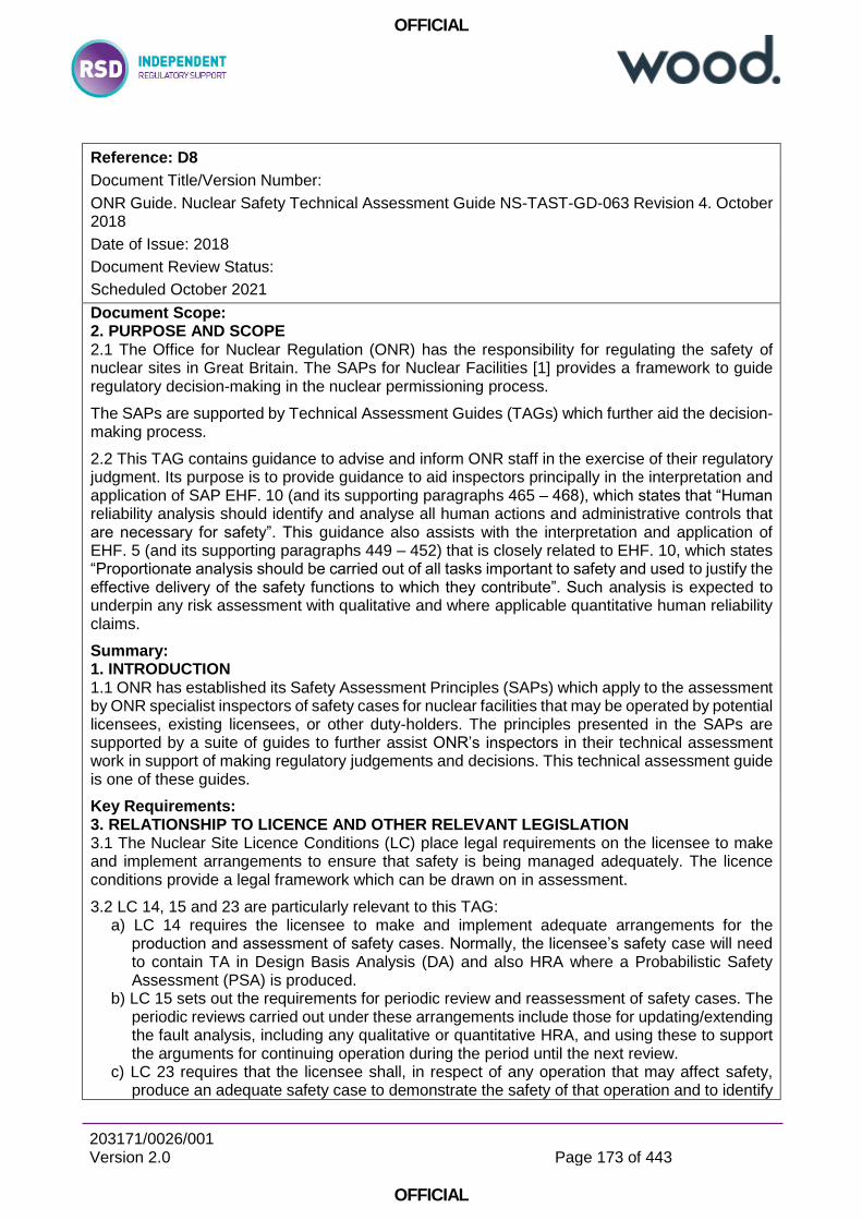
OFFICIAL
203171/0026/001 Version 2.0
Page 173 of 443
OFFICIAL
Reference: D8
Document Title/Version Number:
ONR Guide. Nuclear Safety Technical Assessment Guide NS-TAST-GD-063 Revision 4. October 2018
Date of Issue: 2018
Document Review Status:
Scheduled October 2021
Document Scope: 2. PURPOSE AND SCOPE 2.1 The Office for Nuclear Regulation (ONR) has the responsibility for regulating the safety of nuclear sites in Great Britain. The SAPs for Nuclear Facilities [1] provides a framework to guide regulatory decision-making in the nuclear permissioning process.
The SAPs are supported by Technical Assessment Guides (TAGs) which further aid the decision-making process.
2.2 This TAG contains guidance to advise and inform ONR staff in the exercise of their regulatory judgment. Its purpose is to provide guidance to aid inspectors principally in the interpretation and application of SAP EHF. 10 (and its supporting paragraphs 465 – 468), which states that “Human reliability analysis should identify and analyse all human actions and administrative controls that are necessary for safety”. This guidance also assists with the interpretation and application of EHF. 5 (and its supporting paragraphs 449 – 452) that is closely related to EHF. 10, which states “Proportionate analysis should be carried out of all tasks important to safety and used to justify the effective delivery of the safety functions to which they contribute”. Such analysis is expected to underpin any risk assessment with qualitative and where applicable quantitative human reliability claims.
Summary: 1. INTRODUCTION 1.1 ONR has established its Safety Assessment Principles (SAPs) which apply to the assessment by ONR specialist inspectors of safety cases for nuclear facilities that may be operated by potential licensees, existing licensees, or other duty-holders. The principles presented in the SAPs are supported by a suite of guides to further assist ONR’s inspectors in their technical assessment work in support of making regulatory judgements and decisions. This technical assessment guide is one of these guides.
Key Requirements: 3. RELATIONSHIP TO LICENCE AND OTHER RELEVANT LEGISLATION 3.1 The Nuclear Site Licence Conditions (LC) place legal requirements on the licensee to make and implement arrangements to ensure that safety is being managed adequately. The licence conditions provide a legal framework which can be drawn on in assessment.
3.2 LC 14, 15 and 23 are particularly relevant to this TAG: a) LC 14 requires the licensee to make and implement adequate arrangements for the
production and assessment of safety cases. Normally, the licensee’s safety case will need to contain TA in Design Basis Analysis (DA) and also HRA where a Probabilistic Safety Assessment (PSA) is produced.
b) LC 15 sets out the requirements for periodic review and reassessment of safety cases. The periodic reviews carried out under these arrangements include those for updating/extending the fault analysis, including any qualitative or quantitative HRA, and using these to support the arguments for continuing operation during the period until the next review.
c) LC 23 requires that the licensee shall, in respect of any operation that may affect safety, produce an adequate safety case to demonstrate the safety of that operation and to identify
OFFICIAL
203171/0026/001 Version 2.0
Page 174 of 443
OFFICIAL
conditions and limits necessary in the interests of safety. It is ONR’s expectation that the role and contribution of the operator to safety, which is analysed through both the probabilistic (PSA) and deterministic elements (DBA) aspects of the safety case, will contribute to this process.
3.3 In addition, LC 17 sets out the requirement for management systems which give due priority to safety and for quality management (QM) arrangements for all matters that affect safety. In this respect, Licensees are expected to establish an adequate QM process that is effectively applied during TA and HRA.
3.4 Safety cases, including TA / HRA elements, may be produced to support activities such as construction of new facilities, commissioning, modifications and experiments and decommissioning. These activities, covered by licence conditions 19, 20, 21, 22, 35 and 36, require safety documentation.
3.5 Regulation 3(1) of The Management of Health and Safety Work Regulations 1999 places a legal requirement on dutyholders to produce suitable and sufficient risk assessments. In order to be considered suitable and sufficient, such assessments must identify and consider the impact of human error and the risk of people acting out with established procedures and training.
4. RELATIONSHIP TO SAPS, WENRA REFERENCE LEVELS AND IAEA SAFETY STANDARDS ADDRESSED SAPs 4.1 ONR’s expectations concerning human reliability analysis are set out in a number of SAPs. The primary reference is SAP EHF.10 which states: “Human reliability analysis should identify and analyse all human actions and administrative controls that are necessary for safety”.
4.2 Para 465 to 468 expand upon EHF.10 in relation to the types of safety case analyses HRA may need to be included within (e.g. DBA, PSA and SAA), the types of human actions that should be analysed, the selection and application of probabilistic data for human errors and consideration of dependency.
4.3 SAP EHF.10 is strongly linked with EHF.5 Task Analysis and its supporting text: ”Proportionate analysis should be carried out of all tasks important to safety and used to justify the effective delivery of the safety functions to which they contribute”. 4.4 Paras 449 to 452 expand upon SAP EHF.5 in terms of the factors and demands that
should be considered in task analysis the expected level of descriptive detail and use, and the need to apply task analysis to all actions and controls identified under Principles EHF.3 and EHF.4, so that the safety case demonstrates high confidence in the feasibility of achieving requisite reliability of these actions and controls. 4. RELATIONSHIP TO SAPS, WENRA REFERENCE LEVELS AND IAEA SAFETY STANDARDS ADDRESSED SAPs 4.1 ONR’s expectations concerning human reliability analysis are set out in a number of SAPs. The primary reference is SAP EHF.10 which states: “Human reliability analysis should identify and analyse all human actions and administrative controls that are necessary for safety”.
4.2 Para 465 to 468 expand upon EHF.10 in relation to the types of safety case analyses HRA may need to be included within (e.g. DBA, PSA and SAA), the types of human actions that should be analysed, the selection and application of probabilistic data for human errors and consideration of dependency.
4.5 SAP EHF.3:
OFFICIAL
203171/0026/001 Version 2.0
Page 175 of 443
OFFICIAL
States that “A systematic approach should be taken to identifying human actions that can impact safety for all permitted operating modes and all fault and accident conditions identified in the safety case, including severe accidents”.
4.6 Para 447 to SAP EHF.3: States “This principle includes identifying all the safety actions of personnel responsible for monitoring and controlling the facility and of personnel carrying out maintenance, testing and calibration activities. It also includes consideration of the impact on safety arising from engineers, analysts, managers, directors and other personnel who may not interact directly with plant or equipment”.
Related to EHF.3 is SAP ECS.2 concerning safety classification and its supporting paragraph 164 states: “Where safety functions are delivered or supported by human action, these human actions should be identified and classified on the basis of those functions and their significance to safety. The methods used for determining the classification should be analogous to those used for classifying structures, systems and components.” The methods are outlined in the paragraphs that immediately follow paragraph 164.
4.7 SAP EHF.4: States “Administrative controls needed to keep the facility with its operating rules for normal operation or return the facility back to normal operations should be systematically identified”.
Para 448 supporting SAP EHF.4 states that “The design of these controls should be such that all requirements for personnel action are clearly identified and unambiguous to all those responsible for their implementation”.
4.12 Para 618 supporting SAP FA.2: States “The process for identifying faults should be systematic, auditable and comprehensive and should include… (c) …internal faults from plant failures and human error…”. 4.14 SAP FA. 9: States “DBA should provide an input to…the identification of requirements for operator actions”. 4.15 Para 653 supporting SAP FA13:
States “The PSA should account for contributions to risk including...(e) pre-fault human errors (e.g. misalignments and mis-calibrations); (f) human errors that lead to initiating faults; (g) human errors during the course of the fault sequences including those required for repair or recovery actions; and (h) potential dependencies between separate human activities (either by the same or by different operators)”.
4.16 Para 657 to SAP FA.13: States “When models are used for the calculations of input probabilities, for example, in human errors….then the methodologies used should be justified, and should account for all key influencing factors”.
4.17 Para 658 to SAP FA.13: “Assumptions made regarding the behaviour of the facility or its operators should be justified, and the sensitivity to those assumptions should be analysed”. Other Fault Analysis Principles are also applicable to Human Reliability Analysis. Therefore, Inspectors should also refer to the advice provided in the PSA TAG T/AST/030 when making judgements on the adequacy of a dutyholder’s HRA.
Human Reliability Assessment 5.2 The safety of nuclear installations often requires claims on human action. Where safety important human actions and administrative controls are required and their need is justified, the feasibility and reliability of the actions should be demonstrated qualitatively using task analysis. This qualitative modelling should be used to substantiate any human-based safety claims and the
OFFICIAL
203171/0026/001 Version 2.0
Page 176 of 443
OFFICIAL
quantitative modelling of the probability of the associated human errors. It is considered necessary to carry out task decomposition and analysis of sufficient depth in order to understand what is being assessed, the demands and influencing factors on personnel and to assist with the identification of reasonably practicable design options or improvements to support human reliability. If this is not done, the HRA risks missing factors that may be important to error. ONR therefore considers HRA to be more than just quantification of human error. It is this holistic task analytical process that ONR considers as HRA. Key Themes: ONR NS-TAST-GD-063 Revision 4 highlights the need “Human reliability analysis should identify and analyse all human actions and administrative controls that are necessary for safety”. In the context of the assembly of a bolted joint which is critical to safety then appropriate management arrangements must be in place in order to minimise the possibility of human error. Should the possibility of error be identified in the design basis then it fault tolerance to bolts being incorrectly tensioned would seem appropriate for risks to be ALARP.
OFFICIAL
203171/0026/001 Version 2.0
Page 177 of 443
OFFICIAL
Reference: D9
Document Title/Version Number:
ONR Guide. Categorisation of Safety Functions and Classification of Structures, Systems and Components. Nuclear Safety Technical Assessment Guide NS-TAST-GD-094 Revision 0. November 2015
Date of Issue: 2015
Document Review Status:
Document Scope: 2. PURPOSE AND SCOPE 2.1 This TAG addresses a complex topic and relates to a number of SAPs and licence conditions (LC). It provides advice to ONR assessors in relation to ONR’s expectations regarding the licensee’s / requesting party’s (RP’s) arrangements for identifying and categorising safety functions and identifying and classifying SSCs. The TAG also provides guidance that covers the factors and RGP that should be taken into account when categorising safety functions and classifying SSCs.
2.2 ONR assessors should use this TAG to assess the licensee’s / RP’s safety function categorisation and SSC classification arrangements during generic design assessment (GDA), the permissioning process for new build and plant modification projects.
2.3 This TAG has been organised to provide the key information early, followed by the supporting detail later:
Sections 5.1 to 5.5 presents the principles of safety function identification and categorisation, and SSC identification and classification;
Section 5.6 provides an example of a safety function categorisation scheme.
Section 5.7 provides an example of a SSC classification scheme. These sections provides ONR assessors with a starting point from which to judge the adequacy of the licensee’s / RP’s arrangements;
Section 5.8 provides discipline specific SSC classification guidance;
Annex 1 contains examples to illustrate the categorisation and classification process;
Annex 2 provides further guidance in relation to the classification of mechanical systems.
2.4 This guide is restricted to nuclear safety function categorisation and SSC classification. It does not address the categorisation of documents, maintenance, human actions, engineering changes / plant modification proposals. However, it should be noted that such categorisation should be informed by the safety functions and SSCs to which they relate.
Summary: 1. INTRODUCTION 1.1 The Office for Nuclear Regulation (ONR) has established Safety Assessment Principles (SAPs) [Ref. 1], which guide ONR’s regulatory judgements and actions in the assessment of safety cases for nuclear facilities. The principles presented in the SAPs are supported by a suite of Technical Assessment Guides (TAGs). These further assist ONR assessors in their technical assessments supporting regulatory judgements and decisions. This document is one of those TAGs.
1.2 A nuclear facility should be designed and operated with layers of defence in depth, the purpose of which should be to prevent faults arising, to provide protection in the event that prevention fails and to provide mitigation should an accident occur, (see SAP EKP.3 at paragraph 5.2.1.2). The identification and categorisation of safety functions and the identification and classification of structures, systems and components (SSCs) are key activities that are required to support reasonable and balanced implementation of defence in depth.
OFFICIAL
203171/0026/001 Version 2.0
Page 178 of 443
OFFICIAL
1.3 Safety function categorisation is the process by which safety functions are categorised based on their significance with regard to safety, (see SAP ECS.1 at paragraph 5.2.3.1). A systematic approach to identification of safety functions should be taken. This should take into consideration normal operating, fault and accident conditions, and should be linked to the fault analysis for the facility.
1.4 SSC classification is the process by which SSCs are classified on the basis of their significance in delivering associated safety functions, (see SAP ECS.2). The classification assigned to a SSC indicates the level of confidence required for it to deliver its safety function. It should be used to determine the standards and relevant good practice (RGP) to which SSCs are designed, manufactured, constructed, installed, commissioned, quality assured, maintained, tested and inspected, (see SAP ECS.3).
Key Requirements: See NS-TAST-GD-016 Revision 5. Requirement as per Structural Integrity Key Themes: Safety function categorisation is the process by which safety functions are categorised based on their significance with regard to safety, (see SAP ECS.1 at paragraph 5.2.3.1).
SSC classification is the process by which SSCs are classified on the basis of their significance in delivering associated safety functions, (see SAP ECS.2). The classification assigned to a SSC indicates the level of confidence required for it to deliver its safety function. It should be used to determine the standards and relevant good practice (RGP) to which SSCs are designed, manufactured, constructed, installed, commissioned, quality assured, maintained, tested and inspected, (see SAP ECS.3).
OFFICIAL
203171/0026/001 Version 2.0
Page 179 of 443
OFFICIAL
Reference: D10
Document Title/Version Number:
ONR Guide. Transport Engineering Assessment . Nuclear Safety Technical Assessment Guide NS-TAST-GD-099 Revision 0. April 2017
Date of Issue: 2017
Document Review Status:
Due for revision April 2020
Document Scope: 2. PURPOSE AND SCOPE 2.1 ONR is the Competent Authority (CA) for Great Britain (GB) with responsibility for the civil inland surface transport of radioactive materials (Class 7 dangerous goods).
2.2 ONR regulates the higher hazards via a permissioning regime in which certain transport designs and activities require CA approval. This requires safety submissions (“applications”) to the CA in which duty-holders explain how their designs and/or activities are compliant with the relevant safety regulations. Most of these different types of safety submissions, but not all, require engineering assessment.
2.3 The safety submissions which require engineering assessment are covered in this guidance and are those involving:
material designs (special form, low dispersal radioactive material, fissile exception);
package designs which require CA approval, such as Types B and C packages (which carry radioactive material whose activity exceed a specified limit), and any package carrying fissile materials and UF6);
modifications (usually related to an approved package design);
validation of foreign package designs for use in GB; and
shipment, including special arrangements. 2.7 The scope of this guidance is governed by two primary ONR Transport guidance documents: TRA-PER-GD-014 and TRA-PER-GD-001. Summary: 1.1 The Office for Nuclear Regulations (ONR) has prepared a suite of Technical Assessment Guides (TAG) to assist its inspectors in their technical assessment work in support of making regulatory judgements and decisions. The guides were originally prepared to support ONR’s Safety Assessment Principles, which apply to the assessment by ONR specialist inspectors of safety cases for nuclear facilities. More recently the scope of this suite of guides has been extended to other areas of ONR’s regulatory responsibility including radioactive materials transport. This TAG is one of these latter guides.
Key Requirements: 3. RELATIONSHIP TO LICENCE CONDITIONS AND OTHER RELEVANT LEGISLATION 3.1 Licence conditions, which govern nuclear safety on licensed sites, do not apply to the offsite transport of radioactive materials, which are based on a similar, but parallel, set of safety regulations.
3.2 Legislation governing intra-national and international transport of radioactive materials is based on IAEA Regulations for the Safe Transport of Radioactive Materials, currently Specific Safety Requirements No. SSR-6 (SSR-6). These regulations are translated into European modal regulations (e.g. ADR and RID for road and rail transport respectively), within which radioactive materials are referred to as Class 7 (out of 9 classes) Dangerous Goods. The modal regulations are given legal effect in GB via the Carriage of Dangerous Goods and Use of Transportable
OFFICIAL
203171/0026/001 Version 2.0
Page 180 of 443
OFFICIAL
Pressure Equipment Regulations (CDG), which are Applicable Provisions of The Energy Act(2013).
3.3 In this guide, safety requirements are discussed by reference to the relevant paragraphs in SSR-6. Clearly, any formal communications with duty holders or enforcement action being considered by ONR inspectors should make reference to the appropriate UK legal provisions for the mode of transport in question.
3.4 Supporting guidance for the requirements of SSR-6 [4] is provided by the IAEA document SSG-26 [8]. It should be noted that guidance in SSG-26 has no legal status, unlike the requirements in SSR-6.
5. ADVICE TO INSPECTORS 5.1 The overall purpose of an engineering assessment is to examine a transport safety case against the requirements of the transport regulations as specified in SSR-6.
5.2 SSR-6 [4] is structured so that
Section II defines the terms that are used;
Section III specifies the general provisions relating to radiation protection, emergency response, management system, training etc;
Section IV specifies the applicable activity limits and material restrictions used;
Section V specifies requirements and controls for transport;
Section VI specifies the performance standards required for radioactive material and for packagings and packages;
Section VII specifies the test procedures for demonstrating compliance with the performance standards specified in Section VI, and
Section VIII specifies the requirements for approvals and administration.
5.3 The focus for an engineering assessment is to ascertain if the transport safety case meets the specific requirements in Section VI of SSR-6; these requirements in turn refer out to appropriate parts of Section VII where the test procedures for demonstrating compliance with the requirements are specified.
5.4 Within Section VI, specific paragraphs prescribe the different safety requirements for radioactive material design, packagings and packages, as outlined below:
Requirements for radioactive material (601–605)
Requirements for material excepted from fissile classification (606)
General requirements for all packagings and packages (607–618)
Additional requirements for packages transported by air (619–621)
Requirements for excepted packages (622)
Requirements for industrial packages (623–630)
Requirements for packages containing uranium hexafluoride (631–634)
Requirements for Type A packages (635–651)
Requirements for Type B(U) packages (652–666)
Requirements for Type B(M) packages (667–668)
Requirements for Type C packages (669–672)
Requirements for packages containing fissile material (673–686) Key Themes: NS-TAST-GD-099 Revision 0 is closely aligns the package approval to compliance with IAEA SSR-6. SSR-6 broadly considers only requirements (e.g. loads and conditions) associated to the actual transport of packages and is focussed on Nuclear Safety and containment. CDG, ADR, RID and SSR-6 do not consider potentially more stringent requirements of UK ALARP, which legally mandate the adoption of RGP the adoption of all relevant RGP.

OFFICIAL
203171/0026/001 Version 2.0
Page 181 of 443
OFFICIAL
Noting that Package Design Approval can be considered based solely on SSR-6 compliance and ahead of site and transport safety cases, RSD consider NS-TAST-GD-099 Revision 0 requires revision to clearly state that any design bounding requirements for safe site operations and practices (such as lifting or other UK specific ALARP considerations) should not be ignored in the package design and approval process. In particular, UK ALARP (see “ALARP 6-Pack”) may take precedence and necessitate the implementation of more detailed RGP and management arrangements in relation to the design and execution of specific design features, such as bolted joints.

OFFICIAL
203171/0026/001 Version 2.0
Page 182 of 443
OFFICIAL
Reference: D11
Document Title/Version Number:
ONR Guide. GUIDANCE FOR APPLICATIONS FOR UK COMPETENT AUTHORITY APPROVAL (ONR Transport Permissioning - External Guidance) TRA-PER-GD-014 Revision 1. July 2016
Date of Issue: 2016
Document Review Status:
Due for review
Document Scope: 1. GENERAL INFORMATION 1.1 The Office for Nuclear Regulation (ONR) is the GB Competent Authority (CA) for the civil inland surface transport of Class 7 (radioactive material) dangerous goods. This statutory duty is given to ONR through The Carriage of Dangerous Goods and Use of Transportable Pressure Equipment Regulations (CDG). These regulations transpose into UK law the international standards ADR1 and RID2 for transport of dangerous goods by road and rail, which in turn are based on the IAEA Regulations for the Safe Transport of Radioactive Material (currently SSR-6). Similar regulations apply in Northern Ireland, where the CA for civilian road transport of Class 7 dangerous goods is the Department of the Environment Northern Ireland.
Summary: 1.3 The purpose of the above regulations is to ensure the safety of the transport of radioactive materials. The regulations apply a graded approach, and the aspects of radioactive materials transport involving the higher hazards are regulated by a permissioning regime in which certain designs and activities require prior CA approval.
As well as being the CA for inland transport in GB, ONR also provides advice to and, for this permissioning regime (involving design approvals), acts on behalf of the other civilian UK CAs and agencies mentioned above.
1.4 The purpose of this document, the Applicants Guide, is to provide guidance to organisations applying to ONR for CA approval for new designs, renewal of existing approvals, validation of overseas approvals or modifications to approved designs. The approach taken in this document varies from that in previous versions of the Guide in that much more emphasis is given to how an application should justify safety.
Furthermore unlike previous versions, the document does not attempt to reproduce the requirements of the IAEA regulations. These requirements are set out clearly in SSR-6, and there is supporting guidance in SSG-26 and schedules of regulatory provisions in SSG-33.
Key Requirements: Structure of Applications 2.9 Generally for applications for approval of new designs, shipments or consignments, or where the safety case has been rewritten, the application should be divided into two parts.
Part 1 provides information, including as appropriate the description of the design and the safety limits on operation. Part 1 should explain why the design and its operation are safe. It should summarise and make reference to the detailed evidence in Part 2 that substantiates the claims made in Part 1.
Part 2 contains the technical analysis and justification demonstrating compliance with the regulations, ie the substantiation of the design.
Application Part 1 2.12 Part 1 should:
a) contain general and administrative information, including as appropriate i) name of design of package / material
OFFICIAL
203171/0026/001 Version 2.0
Page 183 of 443
OFFICIAL
ii) contact details of applicant, design authority etc iii) CA identification mark5 iv) type of approval requested, and the regulations under which the application is being made v) modes of transport and any restrictions on the types of vehicles or freight containers vi) whether the design has been approved by the CA of another country vii) details of manufacturers, should the CA wish to inspect viii) information relating to packaging serial numbers ix) the requested date for the Approval (state any strategic or timing factors that may be useful to ONR in prioritising the approval work);
b) for shipment approvals (including special arrangements) provide details as appropriate of: i) the consignor, originator of shipment, consignee, conveyance, packages per load, loads per conveyance ii) the probable or proposed route iii) the place, nature, duration of any transit storage, and person responsible for custody iv) intended dates of shipments or requested duration of approval;
c) provide a full engineering description and specification of the design of the package / material; d) specify the contents including any restrictions on the radioactive contents; e) describe the intended use, and any operational and maintenance requirements, demonstrating their adequacy for the intended use; f) provide details of contingency and emergency arrangements, demonstrating their adequacy; g) provide details of the relevant management system(s) covering all aspects of design, manufacture and use, showing that these arrangements will ensure that the requirements of the safety case will be adequately implemented; h) for design approvals, provide an overview of the safety case – ie the main design principles and safety performance characteristics, summarising and making reference to the detailed evidence (Part 2) that substantiates these claims; i) include a ‘route map’ showing where in the submission compliance with the requirements of the regulations has been demonstrated (paragraph 2.6); and j) for renewal applications, provide a design review (see Section 4).
2.13 The information, claims and arguments in Part 1 should answer the question ‘what makes it safe?’. As indicated above, Part 1 should explain why the design and its operation are safe, summarising and linking to the detailed evidence that substantiates these claims in Part 2 (or possibly, for certain shipment approvals, in other documents eg relating to the package design approval).
2.14 So that the safety case is clear and intelligible, the description and substantiation of the design should identify and present sufficient details of the design features and components that have an effect on:
the containment of radioactive materials (eg seals, flask lid / body assembly);
the control of external radiation levels (eg shielding and associated support structures);
thermal performance (eg internal heat generation and heat removal);
preventing criticality (eg neutron absorbers and associated support structures); and
the impact and structural performance (eg shock absorbers, lifting / securing features).
2.15 Where appropriate, the operational limits of these safety-significant design features and components may be specified to enable these limits to be compared (in Part 2) with claimed performance; this comparison allows the margins to loss of safe performance to be established for each design feature or component.
2.16 The description of the management system should justify how the requirements identified within the safety case will be implemented effectively. These requirements should be collated and clearly presented in the safety case, so they are visible to users of the design. The means of implementation considered should include:

OFFICIAL
203171/0026/001 Version 2.0
Page 184 of 443
OFFICIAL
administrative and operational limits and controls to ensure the design / material is used safely at all times;
the required examination, inspection, maintenance and testing regimes justified in or assumed by the safety case;
the procedures and instructions that need to be followed, eg for operation, handling and maintenance;
supervision of operations, qualification and training of staff, and other safety management requirements; and
inputs to radiological protection programmes and emergency planning.
Application Part 2
2.17 Part 2 of the application should contain the technical analyses, the detailed evidence to support the demonstration that:
the design is compliant with the requirements and performance standards of the regulations; and
the components of the design will meet their safety performance requirements and provide the necessary safety functions during routine, normal and accident conditions of transport, as defined in the regulations.
2.18 In other words, Part 2 should answer the question ‘is it safe?’. Where appropriate it should also determine the safety margins for the safety-significant design features and components by comparing claimed performance with the safety limits prescribed in each regulatory requirement (ie answer the question ‘how safe is it?’). It should show that these safety margins are greater than the uncertainties associated with the results predicted by the analyses.
2.19 Depending on the type of application, Part 2 should provide the detailed technical analyses to demonstrate: the containment of radioactivity; the control of radiation levels; the prevention of criticality; and the prevention of damage caused by heat (both to internal components and externally to the design). It may also be appropriate to provide an underpinning structural analysis of the mechanical behaviour of components and features of the design.
2.20 The purpose and conclusion of each analysis section or report should be stated explicitly, in terms of what specific aspects of equipment safety it is justifying. This makes it easier to follow the safety justification arguments in the submission as a whole, and facilitates consistency between the higher level parts of the submission and their supporting analysis sections. (See also the comment in paragraph 2.3 about informative file / folder names for electronic submissions.)
2.21 The regulations allow for the substantiation of the design (ie the demonstration that it meets the performance standards in the regulations) to be made by physical testing, calculation or reasoned argument. A combination of all three is often used, with the results of physical testing being interpreted by calculation and reasoned argument. This is especially so for mechanical performance testing; demonstration of the adequacy of shielding is often done by calculation but may also involve or be based on physical measurements; criticality safety justifications are more likely to be entirely by calculation. Calculational techniques can vary from bespoke hand-calculations to the use of powerful computer codes involving mathematical models such as finite element or Monte Carlo. It is important not to overlook the significance of reasoned argument, which often provides the cohesion in design substantiations. The applicant may wish to refer to the guidance on Section VII of SSR-6 that is provided in SSG-26.
Desirable Qualities of Applications 2.33 Submissions should:
describe the safety-significant design features and components of the design / consignment (ie those which have an effect on safety) and their safety function;
describe the safety limits or constraints on these safety-significant design features and components, why they are needed and how they are derived;
justify claimed safe performance using appropriate and validated analysis methods;
OFFICIAL
203171/0026/001 Version 2.0
Page 185 of 443
OFFICIAL
keep the arguments simple – even if analysis is complex; and
provide consistency between the higher level safety report (eg Part 1) and the supporting documentation / evidence.
2.34 Submissions should avoid:
presenting unnecessary information, but be focussed on quality and clarity, not quantity;
leaving ‘loose ends’ / gaps in arguments – this casts doubt on the applicant’s quality assurance and makes the regulator ask: ‘what else is wrong?’;
using the CA as a peer reviewer – applicants should do their own internal quality checks and independent reviews; and
being incomplete or having unresolved issues – any analysis and contractual conflicts should be resolved before formal submission to the regulator (notwithstanding any early engagement).
2.35 The desirable qualities of safety cases may be considered under eight headings as follows. Intelligible 2.36 The application, and safety case it contains, should be intelligible and structured logically to meet the needs of those who will use it. There should be a sufficient description of the design and/or operation, and all descriptions and terms should be easy to understand by the key users. All arguments should be cogent and be developed coherently. All references and supporting information should be identified and be easily accessible. There should be a clear trail from claims through the arguments to the evidence that fully supports the conclusions, together with commitments to any future actions. Operational requirements, including maintenance, etc should be clearly defined.
Valid 2.37 The application should be valid. It should accurately represent the intended design and manufacture, and the operational and managerial aspects.
Complete 2.38 The safety case should be complete and contain the information necessary to show that the design, shipment and associated operations will be adequately safe and will be so over the period for which the safety case is valid, ie they will continue to meet all the applicable regulations (explaining why any regulations are considered to be not applicable).
Evidential 2.39 The safety case should be evidential. The arguments developed in the safety case should be supported with verifiable and relevant evidence (ie documented, measurable, etc).
Robust 2.40 The safety case should be robust. It should demonstrate that the design conforms to good engineering practice, sound safety principles and the requirements of the regulations, including appropriate conservatism where there is uncertainty, and adequate safety margins.
Integrated 2.41 The safety case should be integrated. The various parts of the application should be internally consistent. Operational assumptions and controls, and those needed for shipment, should be identified and substantiated.
Balanced 2.42 The safety case should present a balanced account, taking into consideration the level of knowledge and understanding. Areas of relative uncertainty should be identified, not just strengths and claimed conservatisms. Limitations or potential areas for improvement in the design or operation should be explained clearly and openly (eg in the summary or main conclusions of the safety case).
OFFICIAL
203171/0026/001 Version 2.0
Page 186 of 443
OFFICIAL
Forward looking 2.43 The safety case should be forward looking and demonstrate that the proposed design will remain safe throughout a defined life-time, taking account of the effects of ageing and degradation.
Key Themes: TRA-PER-GD-014 Revision 1 is a guide for applicants defining regulatory expectations for the content of applications to the Competent Authority for transport of Radioactive Material.
The highest level expectations are that “Part 1 should explain why the design and its operation are safe. It should summarise and make reference to the detailed evidence in Part 2 that substantiates the claims made in Part 1.” Part 2 for the applications should demonstrate that “the components of the design will meet their safety performance requirements and provide the necessary safety functions during routine, normal and accident conditions of transport, as defined in the regulations.”
RSD note that the regulations (SSR-6) provide the minimum standard safety baseline to allow transfrontier transportation between multiple regulatory domains. The ultimate proof of safety may require consideration of local practices, such as assembly methods and handling, as well as any more stringent safety requirements.

OFFICIAL
203171/0026/001 Version 2.0
Page 187 of 443
OFFICIAL
Reference: D12
Document Title/Version Number:
ONR Guide. ONR Transport Permissioning External Guidance (Special Arrangement Approvals) TRA-PER-GD-016 Revision 0. June 2016
Date of Issue: 2016
Document Review Status:
May 2019 (Overdue)
Document Scope: 2. PURPOSE AND SCOPE 2.1 This document provides guidance on ONR’s expectations for applications for Special Arrangement approval. It should be read in conjunction with the ‘Applicants Guide’4, which provides general guidance on applications for CA approval and their supporting safety cases.
Summary:
1. INTRODUCTION
Background
1.1 The civil transport of radioactive material (Class 7 dangerous goods) is regulated in the UK under Part 3 of The Energy Act 2013 and The Carriage of Dangerous Goods and Use of Transportable Pressure Equipment Regulations 2009 (CDG). CDG implements within GB the international requirements for transport of hazardous goods by road and rail, ADR1 and RID2. These set harmonised standards for the safe transport of dangerous goods within and between member states and are closely based on the requirements of the IAEA Safety Standards ‘Regulations for the Safe Transport of Radioactive Material’ – SSR-6.
1.2 There are similar international requirements based on SSR-6 applicable to sea and air transport namely the International Maritime Dangerous Goods Code and the International Civil Aviation Organisation’s Technical Instructions for the Safe Transport of Dangerous Goods by Air. These are implemented in the UK by The Merchant Shipping Act, The Merchant Shipping (Dangerous Goods and Marine Pollutants) Regulations, The Air Navigation Order and The Air Navigation (Dangerous Goods) Regulations.
1.5 The regulations provide a regulatory framework to ensure the control of risk from the transport of radioactive material is reduced to ‘as low as is reasonably achievable, economic and social factors being taken into account’ (ALARA), which is equivalent to ‘so far as is reasonably practicable’ (SFAIRP) in UK legal terms (and ‘as low as reasonably practicable’ (ALARP)). The regulations achieve this in a harmonised manner through the establishment of a prescriptive set of requirements that must be satisfied to ensure safety and to protect persons, property and the environment from the effects of radiation in the transport of radioactive material.
Key Requirements: 1.7 Situations can arise where it may be impracticable for the transport of consignments of radioactive materials to satisfy all the applicable requirements of the regulations. Such situations may be unplanned events arising during transport, which result in a package in some way not meeting all relevant requirements of the regulations; another example would be the transport of large components generated from nuclear facility decommissioning. Shipments in these situations are permitted under a provision of the regulations known as a Special Arrangement.
1.11 The Special Arrangement approval is described in paragraph 310 of SSR-6. Consignments for which conformity with the other provisions of these Regulations is impracticable shall not be transported except under special arrangement. Provided the competent authority is satisfied that conformity with the other provisions of these Regulations is impracticable and that the requisite standards of safety established by these Regulations have been demonstrated through means
OFFICIAL
203171/0026/001 Version 2.0
Page 188 of 443
OFFICIAL
alternative to the other provisions, the competent authority may approve special arrangement transport operations for single or a planned series of multiple consignments. The overall level of safety in transport shall be at least equivalent to that which would be provided if all the applicable requirements had been met. For consignments of this type, multilateral approval shall be required.
1.12 The above IAEA regulation is transposed into UK law for all modes of transport via the Acts and Regulations discussed above. This provision allows ONR to take an enabling approach to shipments of certain radioactive materials whilst ensuring safety standards are not compromised. Since the normally applicable regulatory requirements are not being satisfied, each Special Arrangement must be specifically approved by the CAs of all the countries through which the package is to be transported (ie multi-lateral approval).
3.5 The Special Arrangement safety case should include as a minimum the following:
a) Demonstration that the design is compliant with the regulations apart from those provisions for which a Special Arrangement is requested.
b) Justification of the reason for the need for a Special Arrangement. This should demonstrate that a suitably robust optioneering process has been conducted in relation to achieving compliance of the package design with relevant Type requirements. This should consider aspects such as a new design, use of alternative packages, modifications etc.
c) Justification, with suitable evidence, of why it is impracticable for the package design being proposed to be used for the shipment(s) to meet all the applicable requirements.
d) Description of the additional safety measures (compensatory measures): ie special precautions or special administrative / operational controls that are to be employed to provide at least an equivalent level of safety to that if all the applicable requirements had been met. This part of the safety case will need to contain much more than a statement of such controls. The safety case should be presented in a claims, arguments and evidence format for each of the compensatory measures to be employed, and clearly justify how and why they will deliver at least an equivalent level of safety to that if all the applicable requirements had been met.
e) The safety case should include a suitably comprehensive and appropriate hazard identification study for all stages of the transport operation in order to be able to identify the nature and magnitude of the hazards and associated risks that will need to be controlled by compensatory measures.
f) An analysis of the hazards and associated risks and of the suitability of the proposed compensatory measures against each of these to deliver at least an equivalent level of safety / risk reduction should be carried out and recorded. Depending on the circumstances and complexity, this part of the safety case (or supporting documentation) may also require formal fault analysis such as design basis / deterministic safety analysis and/or probabilistic safety analysis.
g) The safety case should include suitably robust engineering, management system and where appropriate human factors substantiation of the adequacy of the compensatory measures and feasibility of their implementation during all stages of transport.
Key Themes: There are no applicable themes applicable specifically to the performance or integrity of bolted connections.
Paragraph 1.5 states that the “regulations provide a regulatory framework to ensure the control of risk from the transport of radioactive material is reduced to ‘as low as is reasonably achievable, economic and social factors being taken into account’ (ALARA), which is equivalent to ‘so far as is reasonably practicable’ (SFAIRP) in UK legal terms (and ‘as low as reasonably practicable’ (ALARP)).” RSD consider the definitions of IAEA ALARA and the UK legal definition under HSW legislation to be significantly different and the implications of UK ALARP to be far reaching in Nuclear Safety requirements.
OFFICIAL
203171/0026/001 Version 2.0
Page 189 of 443
OFFICIAL
Reference: D13
Document Title/Version Number:
ONR Guide. General Guidance for Mechanical Engineering Specialism Group. Nuclear Safety Technical Assessment Guide NS-TAST-GD-102 Revision 0. January 2019
Date of Issue: 2019
Document Review Status:
Due Jan 2022
Document Scope: 2. PURPOSE AND SCOPE 2.1 Useful information for inspectors is collected on a frequent basis within ONR; however this information often does not fit into the scope of existing guidance. This guide has been produced to capture such miscellaneous guidance and relevant good practice that does not fit within the scope of any other technical assessment guide (TAG).
2.2 This general TAG is to be used to collate guidance originating from the Mechanical Engineering Specialism Group (MESG). It may however be useful for other inspectors outside the specialism wishing to gain an overview of the appropriate topic areas.
2.3 This TAG identifies guidance and relevant good practice, by topic, in the attached appendices. Each individual appendix states the specific purpose and scope of the guidance, outlines the relevant legislation, good practice guides and internal ONR guidance. All guidance applies to the areas stated within each appendix. It is expected that appendices will be added (or potentially removed) over time.
2.4 The current version of this TAG should be confirmed prior to use.
2.5 This TAG contains guidance to advise and inform ONR staff in making their regulatory judgement.
Summary: 1. INTRODUCTION 1.1 ONR has established Safety Assessment Principles (SAPs) [Ref 2] considered during assessment by specialist inspectors of safety cases for nuclear facilities that may be operated by potential licensees, existing licensees, or other duty-holders. The SAPs are supported by a suite of supporting technical assessment guides to further assist assessment work, making regulatory judgements and determining appropriate assessment decisions. This technical assessment guide supports the mechanical engineering specialism group and includes a collection of topical areas developed through time reflecting developments in recognised good practices.
Key Requirements: APPENDIX 1: QUALITY ASSURED BOLTING IN SAFETY CRITICAL APPLICATIONS A1.1. INTRODUCTION A2.1.1.1 For the purpose of interpretation relating to “fasteners”, BS EN ISO 16426:2002 lists and BS EN ISO 3269:2001 states that these include: bolts, screws, studs, nuts, pins, washers, blind rivets and other related fasteners.
A2.1.1.2 Mechanical Engineering inspection activities have issued challenge regarding the use of fasteners within safety critical structures, systems and components (SSCs) e.g. load-path components or structural fastenings, and whether there was evidence of the quality assurance (QA) documentation available for review.
A2.1.1.3 Previous inspections have shown that robust QA evidence of fasteners meeting their design requirements is inconsistent. A lack of QA evidence leads to further questions regarding claimed reliability of safety critical SSCs.
OFFICIAL
203171/0026/001 Version 2.0
Page 190 of 443
OFFICIAL
A2.1.1.4 This guidance sets regulatory expectations for such applications. This provides a set of high-level requirements concerning quality assurance measures that should be in place as part of good practice in quality management procedures of safety critical SSCs. Guidance on how examination, inspection, maintenance, and testing (EIMT) should be used to ensure the integrity of mechanical joints throughout the lifetime of the plant is also identified (see Section A1.2.4). A1.2. RELEVANT GOOD PRACTICE A1.2.1. Specifications A2.1.1.5 The QA requirements placed on fasteners in safety critical applications should be proportionate to the application and the conditions such fasteners are designed to be subject to (a graded approach). As such, where it is shown that the application is not critical to safety i.e. the fastener does not form part of the safety feature, or failure of the fastener will not weaken or cause the safety function to fail, then the requirements of EN ISO 16426:2002 should be applied and managed by the licensee as a minimum.
A2.1.1.6 Relevant standards, EN ISO 16426:2002 and ASME B18.18:2011, both state that the purchaser must request documentation i.e. it is not (normally) supplied as standard. Where relevant, the licensee should ensure that all appropriate documentation is requested from the manufacturer / supplier. The licensee should also specifically request that results of tests be provided to them.
A2.1.1.7 Bolts should be supplied in individual “lots” (as per EN ISO 16426:2002) and stored at site in “lots” to ensure no commingling. In this regard, suitable documentation in regards to test results and mechanical properties of “lots” shall be held by the licensee for the lifetime of fasteners (as “lots”).
A2.1.1.8 Where bolts are to be used for safety critical applications, applying the standard EN ISO 16426:2002 may not be sufficient and as such, this should be identified within the licensee’s technical specification along with suitable reference to standards for testing and QA management. Equally, a plan for auditing of suppliers should be put in place and executed where deemed appropriate given the safety significance of components, along with suitable evidence and records of audits.
A2.1.1.9 EN ISO 16426:2002 provides a minimal level of QA for fasteners. An adequate specification must be written and provided to the manufacturer. As part of this, a defined set of performance characteristics for the fastener(s) must be provided.
Additionally, it is suggested that the licensee undertakes audit(s) of the manufacturer’s QA and technical procedures to assure itself that the manufacturing, testing and QA practices meet its requirements.
A2.1.1.10 It may also be deemed appropriate (depending on fastener safety significance) to require testing to be done during manufacture to ensure quality. For example, in a “lot” of 1000 bolts, a representative sample for in-manufacture testing may be 10 bolts.
A2.1.1.11 Where testing during manufacture is not possible, it may well be acceptable to the licensee for testing to be carried out post manufacture. BS EN ISO 3269:2000 suggests no more than 5%1, however with larger “lots” at least 1% may be a more suitable figure.
A2.1.1.12 Fastener “lots” used for non-safety critical applications should not be used for safety critical applications unless sufficient evidence that the fasteners meet the design requirements can be provided and are held by the licensee.
A2.1.1.13 Certificates of Conformity have been accepted by licensees as sufficient, however this is seldom sufficient to assure quality of supplied fasteners and as such, documented evidence of material properties should be expected.
A1.2.2. Receipt of QA documentation
OFFICIAL
203171/0026/001 Version 2.0
Page 191 of 443
OFFICIAL
A2.1.1.14 The Licensee shall ensure that where safety critical bolting is identified via the safety case, the documentation required to ensure traceability, mechanical and chemical properties of supplied fasteners is requested within the technical specification(s) or contract documentation.
A1.2.3. Pre-operational considerations
A2.1.1.18 The licensee should consider their own requirements in regards to confirmation of mechanical properties for safety critical fasteners where deemed appropriate e.g. for Safety Function Category A or B [Ref. 2] applications where the fasteners form part of the load path or which failure may result in a radiological incident or compromise nuclear safety.
A2.1.1.20 Prior to the installation of fasteners used in safety critical applications, check(s) to ensure the supplied fasteners meet the minimum design requirements should be undertaken.
A2.1.1.21 This should be expected as part of the QA system. Inspection of the test reports against design requirements will verify this. Acceptance of the fasteners should not take place if they do not meet design requirements.
A1.2.4. In-service inspection
A2.1.1.25 The licensee should, where necessary to support safety case requirements, have in place an inspection regime to confirm that safety critical fasteners remain capable of providing their intended function. This may include checks for signs of corrosion and checks to ensure that fasteners have been tightened sufficiently.
A2.1.1.26 Regular in-service inspection of fasteners should be part of the plant’s planned activities. The licensee’s EIMT schedule(s) should at least inspect for:
surface corrosion on bolts and corrosion of the surrounding parent material(s);
signs of fatigue e.g. bolts identified as “loose” when previously they should have been tightened appropriately;
signs of gapping or “nicks” in threads and equally, checks to determine if bolts have yielded;
where safety critical bolts are used in structural applications, a suitable methodology for in-service inspection or planned replacement strategy should be provided by the licensee; and
where fasteners have “failed” or have been replaced due to signs of yielding or fatigue, then the licensee should have in place a process whereby the faster(s) are tested to identify the failure mode. This information should be used to determine whether “lots” are failing or whether failures are one-offs. The investigation should include an assessment of potential causes and contributory factors to ensure LFE is collated and where appropriate passed on to other plants.
A1.2.5. Records management
A2.1.1.27 The licensee should be able to provide evidence of an appropriately robust record management system in regards to all safety critical components, in accordance with Licence Conditions 6 (Documents, records, authorities and certificates), 17 (Management systems) and 25 (Operational records). Safety critical fasteners should be a part of this.
A1.2.6. Training
A2.1.1.29 Suitable and sufficient training is essential to establish, maintain and develop SQEP resource. Appropriate training for those involved in the design, specification, quality assurance, receipt, storage and use of safety significant fasteners should include a focus on safety critical tasks and address the possible consequences of failing to follow procedures.
A1.2.7. Long established licensees

OFFICIAL
203171/0026/001 Version 2.0
Page 192 of 443
OFFICIAL
A2.1.1.32 It is recognised that application of all of the above elements will prove challenging to long-established licensee’s where such requirements are new. In such cases, a proportionate approach should be taken to provide confidence that the safety critical application of fasteners has been carried out in a manner that reduces the risk of failure to as low as reasonably practicable (ALARP) levels.
A2.1.1.33 Inspectors may be presented with less evidence, but undertake a more detailed discussion with a number of personnel in order to satisfy themselves, or inspectors may require the licensee to provide a report identifying why their arrangements have met RGP. The argument “they haven’t failed yet” is not sufficient, however, evidence to show that the fasteners used are sufficiently robust, are inspected on a regular basis and samples have been tested to show that they meet the design intent may satisfy the inspector.
A1.2.8. Re-use of fasteners in Safety Critical applications
A2.1.1.35 It is a commonly accepted practice across many industries that following replacement or maintenance related activities, fasteners are re-used. In the case of safety critical bolts being re-used, the licensee must have sufficient evidence that:
A2.1.1.36 the same “lot” of fasteners has been tested and the licensee is satisfied that they comply with the design intent;
A2.1.1.37 the licensee can provide a clear set of instructions used by operators to inspect the fasteners for signs of corrosion, wear, fatigue or any other life limiting factors and a record made of such inspections, together with procedures for cleaning, lubrication, tightening etc; and
A2.1.1.38 there is a record of the duration for which such fasteners have been in place and
there is an up-to-date record of cyclic loading that such fasteners have undergone (where this is a risk to failure).
A2.1.1.39 The intent is not to prevent licensees from re-using fasteners in applications where
this is not necessary, however, proportionate control in regards to the inspection (and testing if necessary) techniques undertaken prior to re-use should be an expectation for these safety critical fasteners.
A1.2.9. Additional information
A2.1.1.40 Reference BS EN ISO 16426:2002 is not for specialised applications of fasteners. ASME B18.18 - 2011 identifies that a specific Quality Assurance regime should be put in place for fasteners intended for specialised applications – for example safety critical bolting. Within the ASME standard, these are indicated as Category 3 requirements, and utilise documented and verifiable in-process controls. It states that the producer shall have an independently registered quality management system and that final inspection shall be performed to the requirements of ISO/IEC 17025. Sample sizes are indicated for all categories of application within the ASME standard and may be useful for determining what would be deemed as appropriate.
A2.1.1.41 For metric fasteners used in structural applications, ASME B18.2.6M – 2012 specifically refers to ASME B18.18 in regards to QA requirements, indicating that this ASME standard covers all key applications.
Key Themes: NS-TAST-GD-102 Revision 0 Appendix A is an ONR guide for “Quality Assured Bolting in Safety Critical Applications”.
Mechanical Engineering inspection activities have issued challenge regarding the use of fasteners within safety critical structures, systems and components (SSCs) e.g. load-path components or structural fastenings, and whether there was evidence of the quality assurance (QA) documentation available for review.
OFFICIAL
203171/0026/001 Version 2.0
Page 193 of 443
OFFICIAL
Previous inspections have shown that robust QA evidence of fasteners meeting their design requirements is inconsistent. A lack of QA evidence leads to further questions regarding claimed reliability of safety critical SSCs.
This guidance sets regulatory expectations for such applications. This provides a set of high-level requirements concerning quality assurance measures that should be in place as part of good practice in quality management procedures of safety critical SSCs. Guidance on how examination, inspection, maintenance, and testing (EIMT) should be used to ensure the integrity of mechanical joints throughout the lifetime of the plant is also identified (see Section A1.2.4).
NS-TAST-GD-102 Section A1.2.4 (In-service inspection) states that fasteners should be inspected for:
signs of gapping or “nicks” in threads and equally, checks to determine if bolts have yielded;
where safety critical bolts are used in structural applications, a suitable methodology for in-service inspection or planned replacement strategy should be provided by the licensee; and Noting that for pre-loaded fasteners it is fundamental objective of tightening to tension the bolt to, or marginally beyond its yield stress, then it is concluded that fasteners should not be re-used wherever replaceable.

OFFICIAL
203171/0026/001 Version 2.0
Page 194 of 443
OFFICIAL
6.5 Reviews of IAEA RGP
Reference: E1
Document Title/Version Number: IAEA. Assessment and Management of Ageing of Major Nuclear Power Plant Components Important to Safety: PWR Pressure Vessels 2007 Update. IAEA-TECDOC-1556
Date of Issue: 2007 Update
Document Review Status:
IAEA-TECDOC-1120 is superseded and replaced with this report.
IAEA-TECDOC-1120 documented ageing assessment and management practices for pressurized water reactor (PWR) reactor pressure vessels (RPVs) that were current at the time of its finalization in 1997–1998. Safety significant operating events have occurred since the finalization of the TECDOC, e.g. primary water stress corrosion cracking (PWSCC) of Alloy 600 control rod drive mechanism (CRDM) penetrations and boric acid corrosion/wastage of RPV heads, which threatened the integrity of the RPV heads. These events led to new ageing management actions by both NPP operators and regulators. Therefore it was recognized that IAEA-TECDOC-1120 should be updated by incorporating those new events and their countermeasures.
Document Scope: This report provides the technical basis for managing the ageing of the PWR and pressurized heavy water RPVs to ensure that the required safety and operational margins are maintained throughout the plant service life. The scope of the report includes the following RPV components: vessel shell and flanges, structural weldments, closure studs, nozzles, penetrations and top and bottom closure heads. The scope of this report does not treat RPV internals, the control rod drive mechanisms (CRDMs), or the primary boundary piping used in PWRs. All the various sizes and types of PWR pressure vessels are covered by this report including the WWER (Vodo-Vodianyi Energeticheskii Reactor) plants built in Russia and elsewhere. Boiling water reactor (BWR) pressure vessels and Canadian deuterium-uranium (CANDU) pressure tubes and calandria are covered in separate companion reports.
Summary: IAEA provides a reference for typical:
Western and Soviet design features
Design bases and code requirements in Germany, France, Russia, Japan and US
Construction materials in all regions
Ageing mechanisms, assessment methods and ageing management programmes
Inspection and monitoring requirements and technologies Key Extracts: 1.4. STRUCTURE The designs, materials of construction and physical features of the various PWR pressure vessels are described in Section 2. The codes, regulations and guides used in a number of countries to design RPVs are summarized in Section 3. Section 4. Ageing Mechanisms, identifies the dominant ageing mechanisms, sites, consequences and operating experience. Section 5, Inspection and Monitoring Requirements and Technologies, addresses the application of various inspection technologies to assess the condition of the RPV. Section 6, Ageing Assessment Methods, gives the current practices and data required in assessing degradation of an RPV. Section 7, Ageing Mitigation Methods, describes operational methods used to manage ageing mechanisms (i.e. to minimize the rate of degradation) and maintenance methods used to manage ageing effects (i.e. to correct unacceptable degradation). Section 8 describes an RPV ageing management programme utilizing a systematic ageing management process.
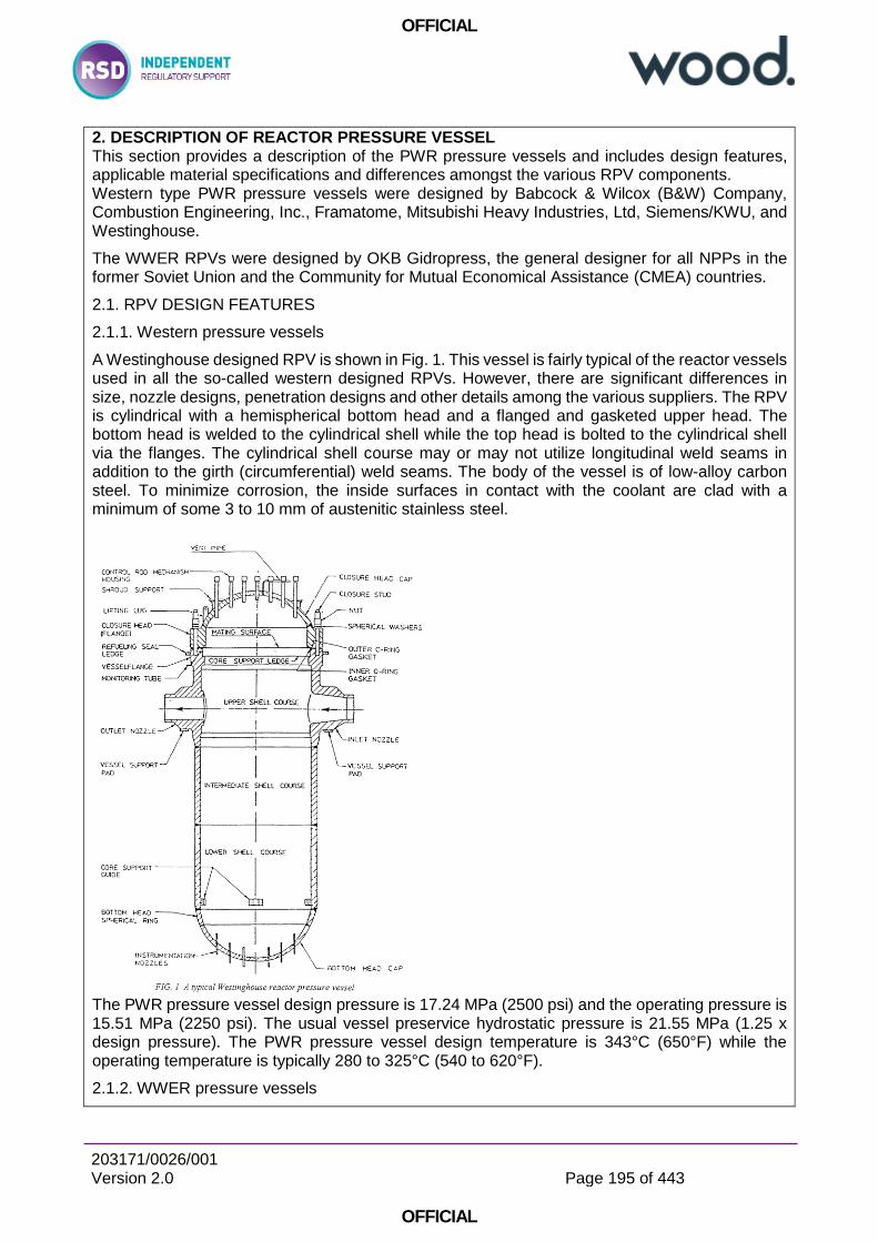
OFFICIAL
203171/0026/001 Version 2.0
Page 195 of 443
OFFICIAL
2. DESCRIPTION OF REACTOR PRESSURE VESSEL This section provides a description of the PWR pressure vessels and includes design features, applicable material specifications and differences amongst the various RPV components. Western type PWR pressure vessels were designed by Babcock & Wilcox (B&W) Company, Combustion Engineering, Inc., Framatome, Mitsubishi Heavy Industries, Ltd, Siemens/KWU, and Westinghouse.
The WWER RPVs were designed by OKB Gidropress, the general designer for all NPPs in the former Soviet Union and the Community for Mutual Economical Assistance (CMEA) countries.
2.1. RPV DESIGN FEATURES
2.1.1. Western pressure vessels
A Westinghouse designed RPV is shown in Fig. 1. This vessel is fairly typical of the reactor vessels used in all the so-called western designed RPVs. However, there are significant differences in size, nozzle designs, penetration designs and other details among the various suppliers. The RPV is cylindrical with a hemispherical bottom head and a flanged and gasketed upper head. The bottom head is welded to the cylindrical shell while the top head is bolted to the cylindrical shell via the flanges. The cylindrical shell course may or may not utilize longitudinal weld seams in addition to the girth (circumferential) weld seams. The body of the vessel is of low-alloy carbon steel. To minimize corrosion, the inside surfaces in contact with the coolant are clad with a minimum of some 3 to 10 mm of austenitic stainless steel.
The PWR pressure vessel design pressure is 17.24 MPa (2500 psi) and the operating pressure is 15.51 MPa (2250 psi). The usual vessel preservice hydrostatic pressure is 21.55 MPa (1.25 x design pressure). The PWR pressure vessel design temperature is 343°C (650°F) while the operating temperature is typically 280 to 325°C (540 to 620°F).
2.1.2. WWER pressure vessels
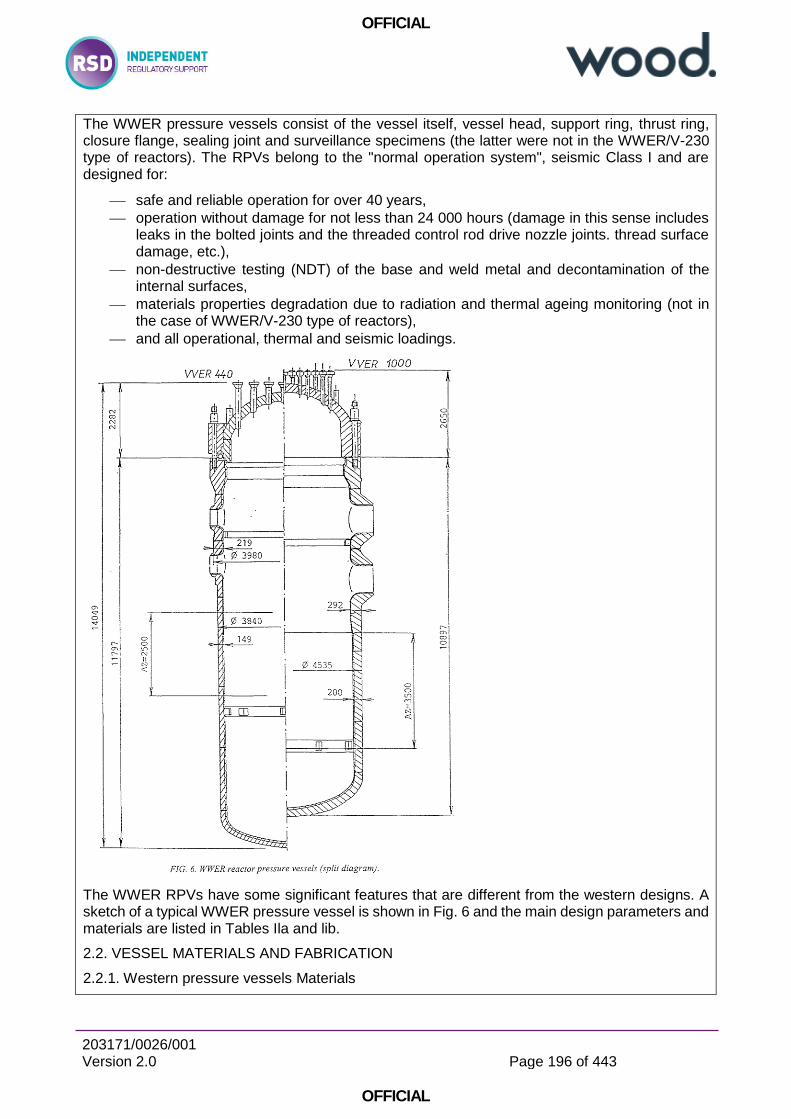
OFFICIAL
203171/0026/001 Version 2.0
Page 196 of 443
OFFICIAL
The WWER pressure vessels consist of the vessel itself, vessel head, support ring, thrust ring, closure flange, sealing joint and surveillance specimens (the latter were not in the WWER/V-230 type of reactors). The RPVs belong to the "normal operation system", seismic Class I and are designed for:
safe and reliable operation for over 40 years,
operation without damage for not less than 24 000 hours (damage in this sense includes leaks in the bolted joints and the threaded control rod drive nozzle joints. thread surface damage, etc.),
non-destructive testing (NDT) of the base and weld metal and decontamination of the internal surfaces,
materials properties degradation due to radiation and thermal ageing monitoring (not in the case of WWER/V-230 type of reactors),
and all operational, thermal and seismic loadings.
The WWER RPVs have some significant features that are different from the western designs. A sketch of a typical WWER pressure vessel is shown in Fig. 6 and the main design parameters and materials are listed in Tables Ila and lib.
2.2. VESSEL MATERIALS AND FABRICATION
2.2.1. Western pressure vessels Materials
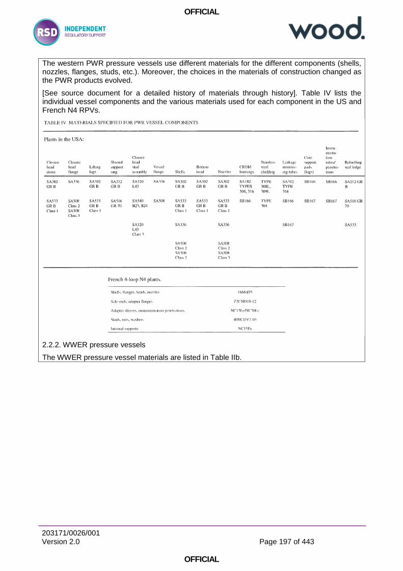
OFFICIAL
203171/0026/001 Version 2.0
Page 197 of 443
OFFICIAL
The western PWR pressure vessels use different materials for the different components (shells, nozzles, flanges, studs, etc.). Moreover, the choices in the materials of construction changed as the PWR products evolved.
[See source document for a detailed history of materials through history]. Table IV lists the individual vessel components and the various materials used for each component in the US and French N4 RPVs.
2.2.2. WWER pressure vessels
The WWER pressure vessel materials are listed in Table IIb.
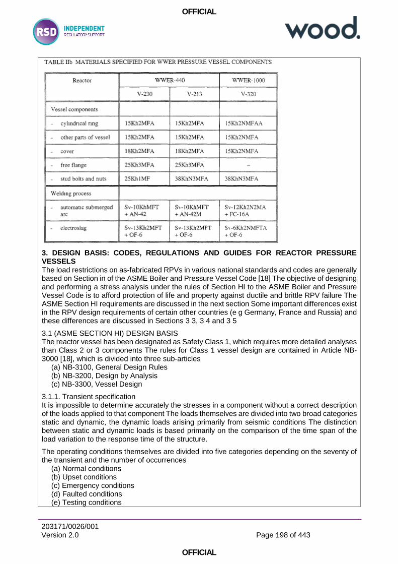
OFFICIAL
203171/0026/001 Version 2.0
Page 198 of 443
OFFICIAL
3. DESIGN BASIS: CODES, REGULATIONS AND GUIDES FOR REACTOR PRESSURE VESSELS The load restrictions on as-fabricated RPVs in various national standards and codes are generally based on Section in of the ASME Boiler and Pressure Vessel Code [18] The objective of designing and performing a stress analysis under the rules of Section HI to the ASME Boiler and Pressure Vessel Code is to afford protection of life and property against ductile and brittle RPV failure The ASME Section HI requirements are discussed in the next section Some important differences exist in the RPV design requirements of certain other countries (e g Germany, France and Russia) and these differences are discussed in Sections 3 3, 3 4 and 3 5
3.1 (ASME SECTION HI) DESIGN BASIS The reactor vessel has been designated as Safety Class 1, which requires more detailed analyses than Class 2 or 3 components The rules for Class 1 vessel design are contained in Article NB-3000 [18], which is divided into three sub-articles
(a) NB-3100, General Design Rules (b) NB-3200, Design by Analysis (c) NB-3300, Vessel Design
3.1.1. Transient specification It is impossible to determine accurately the stresses in a component without a correct description of the loads applied to that component The loads themselves are divided into two broad categories static and dynamic, the dynamic loads arising primarily from seismic conditions The distinction between static and dynamic loads is based primarily on the comparison of the time span of the load variation to the response time of the structure.
The operating conditions themselves are divided into five categories depending on the seventy of the transient and the number of occurrences
(a) Normal conditions (b) Upset conditions (c) Emergency conditions (d) Faulted conditions (e) Testing conditions
OFFICIAL
203171/0026/001 Version 2.0
Page 199 of 443
OFFICIAL
Normal conditions are those which exist during normal running of the plant. Upset conditions are deviations from the normal conditions but are anticipated to occur often enough that provisions for them must be made in the analysis. These transients are those that do not result in forced outage, or if forced outage occurs, the restoration of power does not require mechanical repair. Emergency conditions are deviations from normal which require shutdown and may require repair and must be considered in order to assure no gross loss of structural integrity. Faulted conditions are deviations from normal, are extremely low probability, but may result in loss of integrity and operability of the system. Testing conditions are pressure overload tests, or other tests on the primary system.
For a PWR, the definitions of all operating transients are contained in the equipment specifications and are designed to represent the conditions under which a specific plant would operate.
3.1.2. Analysis of normal and upset conditions
Description of stress categories The rules for design of Class 1 vessels make use of both realistic and accurate analysis techniques and failure criteria and therefore have relaxed overly restrictive safety factors used in the past. The calculated value of stress means little until it is associated with a location and distribution in the structure and with the type of loading which produced it. Different types of stress have different degrees of significance and must, therefore, be assigned different allowable values…. Likewise, a thermal stress can often be allowed to reach a higher value than one which is produced by dead weight or pressure Therefore, a new, set of design criteria were developed which shifted the emphasis away from the use of standard configurations and toward the detailed analyses of stresses The setting of allowable stress values required dividing stresses into categories and assigning different allowable values to different groups of categories.
Different types of stress require different limits, and before establishing these limits, it was necessary to choose the stress categories to which limits should be applied. The categories and sub-categories chosen were as follows:
A. Primary stress 1. General primary membrane stress 2. Local primary membrane stress 3. Primary bending stress.
B. Secondary stress C. Peak stress.
The chief characteristics of these stresses may be described as follows: (a) Primary stress is a stress developed by the imposed loading which is necessary to satisfy
the laws of equilibrium between external and internal forces and moments. The basic characteristic of a primary stress is that it is not self-limiting. If a primary stress exceeds the yield strength of the material through the entire thickness, the prevention of failure is entirely dependent on the strain-hardening properties of the material.
(b) Secondary stress is a stress developed by the self-constraint of a structure. It must satisfy an internal strain pattern rather than equilibrium with an external load. The basic characteristic of a secondary stress is that it is self-limiting. These stresses are caused by thermal expansion or discontinuity conditions. The main concern with secondary stresses is that they may result in localized yielding or distortion.
(c) Peak stress is the highest stress in the region under consideration. The basic characteristic of a peak stress is that it causes no significant distortion and is objectionable mostly as a possible source of fatigue failure.
Stress intensity limits [Discussion of derivation of stress intensity limits omitted for brevity]
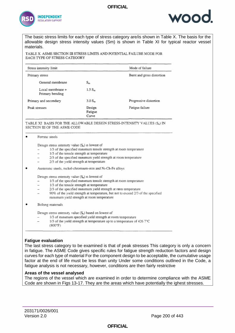
OFFICIAL
203171/0026/001 Version 2.0
Page 200 of 443
OFFICIAL
The basic stress limits for each type of stress category are/is shown in Table X. The basis for the allowable design stress intensity values (Sm) is shown in Table XI for typical reactor vessel materials.
Fatigue evaluation The last stress category to be examined is that of peak stresses This category is only a concern in fatigue. The ASME Code gives specific rules for fatigue strength reduction factors and design curves for each type of material For the component design to be acceptable, the cumulative usage factor at the end of life must be less than unity Under some conditions outlined in the Code, a fatigue analysis is not necessary, however, conditions are then fairly restrictive
Areas of the vessel analysed The regions of the vessel which are examined in order to determine compliance with the ASME Code are shown in Figs 13-17. They are the areas which have potentially the ighest stresses.
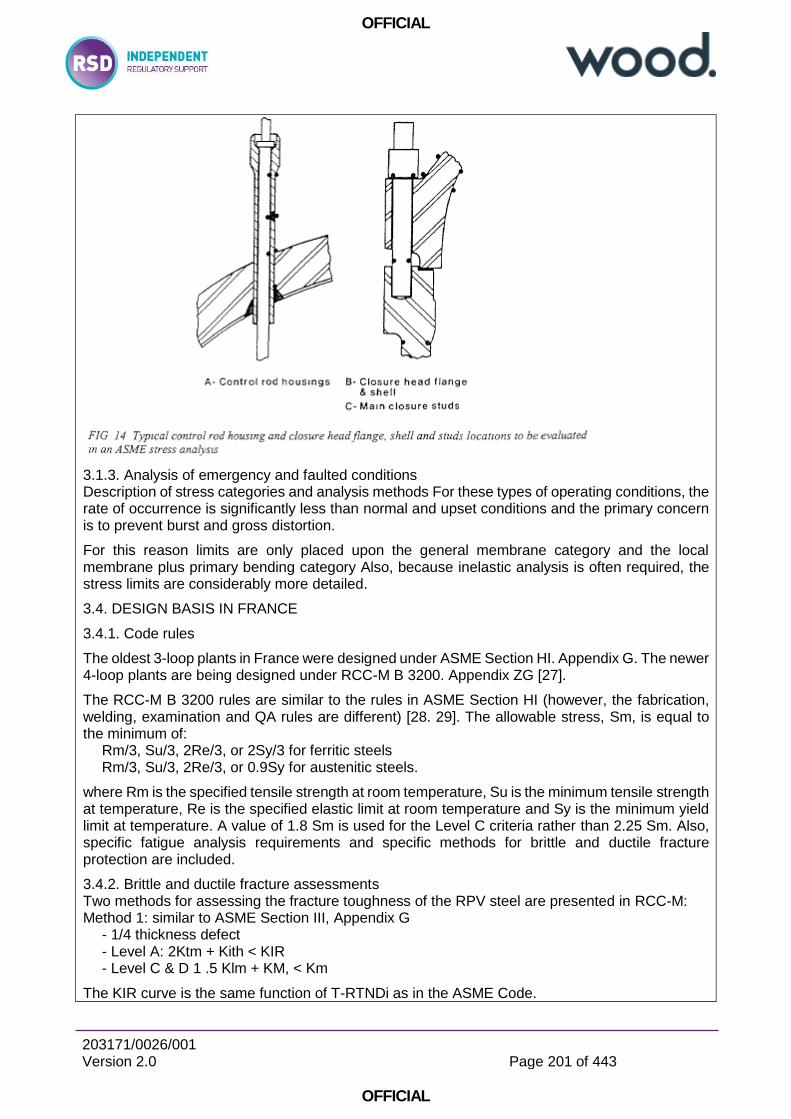
OFFICIAL
203171/0026/001 Version 2.0
Page 201 of 443
OFFICIAL
3.1.3. Analysis of emergency and faulted conditions Description of stress categories and analysis methods For these types of operating conditions, the rate of occurrence is significantly less than normal and upset conditions and the primary concern is to prevent burst and gross distortion.
For this reason limits are only placed upon the general membrane category and the local membrane plus primary bending category Also, because inelastic analysis is often required, the stress limits are considerably more detailed.
3.4. DESIGN BASIS IN FRANCE
3.4.1. Code rules
The oldest 3-loop plants in France were designed under ASME Section HI. Appendix G. The newer 4-loop plants are being designed under RCC-M B 3200. Appendix ZG [27].
The RCC-M B 3200 rules are similar to the rules in ASME Section HI (however, the fabrication, welding, examination and QA rules are different) [28. 29]. The allowable stress, Sm, is equal to the minimum of:
Rm/3, Su/3, 2Re/3, or 2Sy/3 for ferritic steels Rm/3, Su/3, 2Re/3, or 0.9Sy for austenitic steels.
where Rm is the specified tensile strength at room temperature, Su is the minimum tensile strength at temperature, Re is the specified elastic limit at room temperature and Sy is the minimum yield limit at temperature. A value of 1.8 Sm is used for the Level C criteria rather than 2.25 Sm. Also, specific fatigue analysis requirements and specific methods for brittle and ductile fracture protection are included.
3.4.2. Brittle and ductile fracture assessments Two methods for assessing the fracture toughness of the RPV steel are presented in RCC-M: Method 1: similar to ASME Section III, Appendix G
- 1/4 thickness defect - Level A: 2Ktm + Kith < KIR - Level C & D 1 .5 Klm + KM, < Km
The KIR curve is the same function of T-RTNDi as in the ASME Code.
OFFICIAL
203171/0026/001 Version 2.0
Page 202 of 443
OFFICIAL
Method 2: An initial 15 mm crack is postulated, the end of life size is then evaluated using the Level A transient fatigue crack growth, the end of life Kj (based on J estimation scheme) is evaluated and the various criteria presented in Table XIX are used.
3.5. WWER DESIGN BASIS All the WWER RPVs were designed according to the Soviet (Russian) Codes in effect at the time of their design and manufacturing. Requirements for assuring general safety and design life were summarized in Rules for Design and Safe Operation of Components of NPPs,
Test and Research Reactors and Stations [31] issued in 1973: these rules were updated in 1990 as Rules for Design and Safe Operation of Components and Pipings of NPPs [32]. The design itself (including the necessary stress analysis and the design lifetime calculations) was carried out mostly according to the Code for Strength Calculations of Components of Reactors, Steam-Generators and Pipings of NPPs, Test and Research Reactors and Stations [33] issued in 1973, which was updated in 1989 as the Code for Strength Calculations of Components and Piping of Nuclear Power Plants, Moscow, 1989 [34]. The former Code was used for the design and analysis in the Pre-operational Safety Reports and the Supplementary Manufacturing Reports, the newer one is now also used for calculations within the Operational Safety Reports and other assessments. All these Soviet Codes were accepted also by all the national regulatory bodies of the countries operating these reactors.
3.5.1. Code requirements in Russia The RPVs and primary system piping at all the major nuclear facilities, i.e. the PWRs, nuclear heating centres, as well as research and test reactors with operating temperatures over 600°C (i.e. with gas or liquid metal coolants) are safety related components and must be evaluated according to the Codes and Rules [31-34]. With respect to the WWER RPVs.
Special analysis requirements are also provided for radiation embrittlement.
The Code [33] is divided into 5 parts: (1) General Statements deal with the area of Code application and basic principles used in the Code. (2) Definitions gives full description of the most important operational parameters as well as parameters of calculations. (3) Allowable stresses, strength and stability conditions. (4) Calculation of basic dimensions deals with the procedure for choosing the component wall thickness, provides strength decrease coefficients and hole reinforcement values. Further, formulas for analysis of flange and bolting joints are also given. (5) Validating calculations are the most important part of the Code. These detailed calculations contain rules for the classification of stresses as well as steps for stress determination. Further, detailed calculations for different possible failure mechanisms are required and their procedures and criteria are given:
- calculation of static strength, - calculation of stability, - calculation of cyclic strength (fatigue), - calculation of long-term cyclic strength (creep—fatigue) [not applicable for WWER RPV], - calculation of resistance against brittle fracture, - calculation of long-term static strength (creep) [not applicable for WWER RPV], - calculation of progressive form change [not applicable for WWER RPV], - calculation of seismic effects, - calculation of vibration strength (ultra-high frequency fatigue).
3.5.2. Transient specification In accordance with the NPP elements and systems classification as described in the General Provisions on NPP Safety Assurance [35], the WWER pressure vessel belongs to the 1st class of
OFFICIAL
203171/0026/001 Version 2.0
Page 203 of 443
OFFICIAL
safety. Therefore, appropriately more rigid requirements are placed on the quality of the design, as well as the fabrication and operation of the RPV.
3.5.3. Stress analysis The validating calculations require a detailed stress analysis to determine the different types of stresses and classify of them so as to be able to apply prescribed stress limits and safety coefficients. Detailed analysis of various failure mechanisms are also required.
Categories of stresses
In principle, the stresses are divided into the following categories: σm general membrane stresses σMI local membrane stresses σb general bending stresses σBI local bending stresses σT general temperature stresses σTL local temperature stresses σk compensation stresses σmw mean tensile stresses in bolted sections, created by mechanical loading.
Checking calculations are carried out, applying to all existing loadings (including temperature effects) and all operating regimes.
Stress intensities, which are compared with allowable ones, are determined using the theory of maximum shear stresses with the exception of calculations of resistance against brittle failure, in which the theory of maximum normal stresses is applied. Linear-elastic analysis techniques are used to calculate stresses in locations without stress concentrations. For fatigue calculations in the elastic-plastic region of loading, so-called pseudo-elastic stresses are used. These stresses are obtained by multiplication of the elastic-plastic strains in a given location by the Young's modulus.
Stress intensities are divided into four groups, according to their type: (σ)1 stress intensities calculated from the general membrane stress components (σ)2 stress intensities calculated from the sum of the general or local membrane and bending stress components (σ)3W stress intensities calculated from the sum of the mean tensile stresses in a bolted section, including the tightening loads and the effects of temperature (σ)4W stress intensities caused by mechanical and temperature effects, including tensioned bolt loadings and calculated from stress components of tension, bending and twisting in bolts while the stress intensity ranges for RPVs are defined as:
3.5.4. Design and analysis against brittle failure All necessary requirements and analysis procedures as well as material data are given in the new version of the Code [34] (only the temperature approach was given in the previous version of the Code [33]). The whole procedure is summarized in the Chapter "Calculation of Resistance Against Brittle Fracture". The Code can also be used for components manufactured before the Code was issued, which are now in operation, or under completion, if the procedure has been approved by the regulatory body. The procedures in the Code are based on the principles of LEFM with the use of static plain strain fracture toughness, KIC, only. The Code provides allowable stress intensity factor curves (defined also by formulas) as a function of reference temperature, a postulated flaw and a KI expression for normal operating conditions, pressure tests and upset conditions and emergency conditions. In principle, the procedure is very similar to the one from the ASME Code, some differences result from the different materials and reactor designs used.
4. AGEING MECHANISMS This section describes the age related degradation mechanisms that could affect PWR RPV components and evaluates the potential significance of the effects of these mechanisms on the continued safety function performance of these components throughout the plant service life.
OFFICIAL
203171/0026/001 Version 2.0
Page 204 of 443
OFFICIAL
The set of age related degradation mechanisms evaluated in this section is derived from a review and evaluation of relevant operating experience and research. This set consists of the following mechanisms:
1. Radiation embrittlement 2. Thermal ageing 3. Temper embrittlement 4. Fatigue 5. Corrosion
- Intergranular attack and PWSCC of Alloy 600 components, Alloy 82/182 welds, radial keys, etc. - General corrosion and pitting - Boric acid corrosion
6. Wear.
4.1. RADIATION EMBRITTLEMENT 4.1.1. Radiation embrittlement of western pressure vessels The degree of embrittlement and hardening induced in ferritic steels after exposure to fast neutron radiation is an issue of the utmost importance in the design and operation of NPPs. The area of the RPV surrounding the core (called the beltline region) is the most critical region of the primary pressure boundary system because it is subjected to significant fast neutron bombardment.
4.2. THERMAL AGEING 4.2.1. Description of mechanism Thermal ageing is a temperature, material state (microstructure) and time dependent degradation mechanism. The material may lose ductility and become brittle because of very small microstructural changes in the form of precipitates coming out of solid solution. In the case of RPV steel with impurity copper, the important precipitates are copper-rich (however, there could be other precipitates). The precipitates block dislocation movement thereby causing hardening and embrittlement. The impurity copper in RPV steel is initially trapped in solution in a super-saturated state. With time at normal PWR operating temperatures (~290°C), it may be ejected to form stable precipitates as the alloy strives toward a more thermodynamically stable state, even if there is no radiation damage. As discussed in Section 4.1, neutron-induced structural damage promotes the copper precipitation process.
The effects of long-term aging at temperatures up to 350°C on the ductile-to-brittle transition temperature of RPV steels have recently been summarized in a paper by Corwin et al. [47]. The work was sponsored by the USNRC and performed at the Oak Ridge National Laboratory and the University of California, Santa Barbara. Corwin et al. concluded that "most of the data from the literature suggest that there is no embrittlement in typical RPV steels at these temperatures for times as great as 100 000 h...."
4.3. TEMPER EMBRITTLEMENT 4.3.2. Significance for western pressure vessels RPV steels with phosphorus content well above about 0.02 wt% may be susceptible to temper embrittlement during fabrication. However, the western RPV materials normally contained less than 0.020 wt% phosphorus. Therefore, it is unlikely that any western RPVs will exhibit temper embrittlement.
4.4 FATIGUE 4.4.1. Description of mechanism Fatigue is the initiation and propagation of cracks under the influence of fluctuating or cyclic applied stresses. The chief source of cyclic stresses are vibration and temperature fluctuations. As discussed previously, the PWR RPV is designed so that no subcomponent of the RPV is stressed above the allowable limits described in the ASME Boiler and Pressure Vessel Code, Section HI (or equivalent national codes) during transient conditions and the allowable cyclic
OFFICIAL
203171/0026/001 Version 2.0
Page 205 of 443
OFFICIAL
fluctuations do not violate Miner's fatigue rule. Once a crack is detected, it's behaviour under cyclic loading is analysed according to Section XI of the ASME Code or similar codes.
The RPV should be designed in such a way that no subcomponent is stressed above the allowable limit, which is a usage factor of 1. Even if the usage factors go slightly above 1, fatigue cracks are not expected because the safety factors discussed in Section 3 are used in the design.
4.4.2. Significance Significance for western pressure vessels The RPV closure studs have the highest usage factor of any the subcomponents. However, the usage factor for the RPV closure studs are of the order of 0.66 for the 40-year design life. The head penetrations for the control rod drives and the vent tubes have very low fatigue usage factors. The RPV inlet and outlet nozzles also have relatively low fatigue usage factors. Unless there is some condition that results in extreme vibration to any of the RPV subcomponents, fatigue damage is considered an insignificant degradation mechanism in the assessment and management of the PWR pressure vessels.
Significance for WWER pressure vessels From a fatigue point of view, the most important subcomponents of the WWER pressure vessels are the closure studs. The lifetime of the WWER-440 closure studs is limited to some 15 years of operation, when the expected usage factor will reach one. However, there is little chance of failure because these studs are tested every four years by ultrasonic and eddy current methods. Moreover, their exchange is a standard maintenance procedure, which is planned in advance.
4.5.1. Primary water stress corrosion cracking (PWSCC) of the PWR CRDM penetrations NOT APPLICABLE FOR HEAD BOLTS
4.5.2. General corrosion and pitting on the inside surfaces NOT APPLICABLE FOR HEAD BOLTS
4.5.3. Boric acid corrosion of outer surfaces Aerated solutions of boric acid can attack carbon and low alloy steels If a leak exists somewhere in the vicinity of the RPV head, bone acid corrosion of the low alloy steel plates or forgings is possible Boric acid leakage can result in very high and localized corrosion rates, i e , mm per year Sporadic leakage has been observed from flanges (O-ring seals), closure studs and instrumentation tubes of western PWRs Sporadic leakage has also been observed from some of the WWER control rod drive nozzle flanges and from around the threads for the vessel head closure studs To exclude more leakage of this type, the nickel O-rings used in the WWER control rod drive nozzle flanges were exchanged for graphite O-rings While bone acid leakage is not considered a safety issue, it can become an economic problem Therefore, boric acid leakage should be considered a significant degradation mechanism in the assessment and management of the PWR pressure vessels.
Operating experience Turkey Point Unit 4: In 1987, the plant operating staff found over 230 kg (500 pounds) of boric acid crystals on the RPV head. They also found crystals in the exhaust cooling ducts for the CRDMs. After removing the boric acid and steam cleaning the head, the plant staff noted severe corrosion in several areas.
… The borated reactor coolant leaking from the conoseal flowed down the head insulation and beneath the insulation to the exposed head. This caused damage to the head, the conoseal clamps and some of the head bolts. Three of the 58 head studs were so corroded that the bolts and nuts had to be replaced.
Ringhals Unit 2: The plant staff noted a somewhat higher leakage rate than usual from the primary system during the summer of 1985. The leakage rate was about 2-3 times higher than expected but well within the limit of the technical specifications. Despite extensive searching, the staff could not find any

OFFICIAL
203171/0026/001 Version 2.0
Page 206 of 443
OFFICIAL
leaking valve and thus assumed that maintenance of the steam generator had been less effective than usual and attributed the higher rate to steam generator leakage.
During startup after a shutdown in December 1985 for preventive steam generator maintenance, inspection showed that the reactor flange was leaking. The head was lifted and the reactor flange and head flange were cleaned and inspected. The reactor flange had some minor defects in the groove for the 0-rings. Four to six head studs had been affected by the leakage. The studs were cleaned and inspected.
1. INSPECTION AND MONITORING REQUIREMENTS AND TECHNOLOGIES RPVs in the USA are inspected in accordance with Section XI of the ASME Code [21]. There are three types of examinations used during in-service inspection: visual, surface and volumetric. The three types of in-service inspections are a carry-over from the pre-service inspection (PSI) that is required for the RPVs. Inspection plans are prepared for the PSI (if required), the first in-service inspection interval and subsequent in-service inspection intervals.
Each NPP follows a pre-service and in-service inspection programme based on selected intervals throughout the design life of the plant. The RPV inspection category is described in Table IWB 2500-1 of Section XI of the ASME Code, which details the inspection requirements. The in-service inspection intervals are determined in accordance with the schedule of Inspection Programme A of IWA-2410, or optionally Inspection Programme B of IWA-2420. Programme A is modeled on the traditional bi-modal distribution which is based on the expectation that most problems will be encountered either in the first few years of operation or late in plant service life. Programme B is modeled on the expectation that plant problems will be uniformly distributed with respect to time. For Programme B, 16 per cent of the required inspections are to be completed in the third year, another 34 per cent of the required inspection by the seventh year and the remainder by the tenth year of operation.
All studs and threaded stud holes in the closure head need surface and volumetric examinations at each inspection interval.
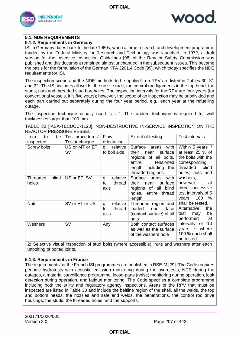
OFFICIAL
203171/0026/001 Version 2.0
Page 207 of 443
OFFICIAL
5.1. NDE REQUIREMENTS 5.1.2. Requirements in Germany ISI in Germany dates back to the late 1960s, when a large research and development programme funded by the Federal Ministry for Research and Technology was launched. In 1972, a draft version for the Inservice Inspection Guidelines [98] of the Reactor Safety Commission was published and this document remained almost unchanged in the subsequent issues. This became the basis for the formulation of the German KTA 3201.4 Code [99], which today specifies the NDE requirements for ISI.
The inspection scope and the NDE-methods to be applied to a RPV are listed in Tables 30, 31 and 32. The ISI includes all welds, the nozzle radii, the control rod ligaments in the top head, the studs, nuts and threaded stud boreholes. The inspection intervals for the RPV are four years (for conventional vessels, it is five years); however, the scope of an inspection may be subdivided and each part carried out separately during the four year period, e.g., each year at the refuelling outage.
The inspection technique usually used is UT. The tandem technique is required for wall thicknesses larger than 100 mm.
TABLE 30 [IAEA-TECDOC-1120]. NON-DESTRUCTIVE IN-SERVICE INSPECTION ON THE REACTOR PRESSURE VESSEL
Item to be inspected
Test procedure / Test technique
Flaw orientation
Extent of testing Test intervals
Screw bolts US or MT or ET, SV
q, relative to bolt axis
Surface areas with their near surface regions of all bolts, entire tensioned length including the threaded regions.
Within 5 years 2) at least 25 % of the bolts with the corresponding threaded blind holes, nuts and washers, however, at three successive test intervals of 5 years. 100 % shall be tested. Alternative, the test may be performed at intervals of 10 years 2) where 100 % each shall be tested.
Threaded blind holes
US or ET, SV q, relative to thread axis
Surface areas with their near surface regions of all blind holes, entire thread length
Nuts
SV or ET or US q, relative to thread axis
Threaded region and loaded end face (contact surface) of all nuts
Washers SV Any Both contact surfaces as well as the surface of the washers hole
2) Selective visual inspection of stud bolts (where accessible), nuts and washers after each unbolting of bolted joints.
5.1.3. Requirements in France The requirements for the French ISI programmes are published in RSE-M [29]. The Code requires periodic hydrotests with acoustic emission monitoring during the hydrotests, NDE during the outages, a material surveillance programme, loose-parts (noise) monitoring during operation, leak detection during operation, and fatigue monitoring. The Code specifies a complete programme including both the utility and regulatory agency inspections. Areas of the RPV that must be inspected are listed in Table 33 and include the beltline region of the shell, all the welds, the top and bottom heads, the nozzles and safe end welds, the penetrations, the control rod drive housings, the studs, the threaded holes, and the supports.
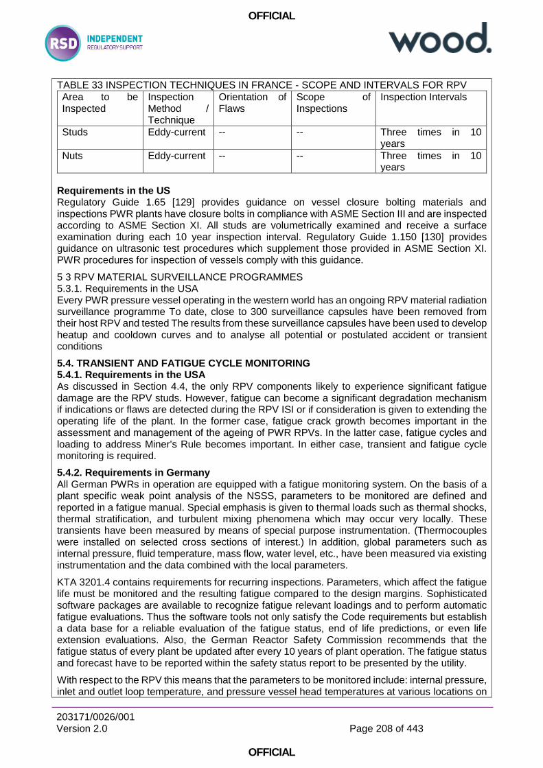
OFFICIAL
203171/0026/001 Version 2.0
Page 208 of 443
OFFICIAL
TABLE 33 INSPECTION TECHNIQUES IN FRANCE - SCOPE AND INTERVALS FOR RPV
Area to be Inspected
Inspection Method / Technique
Orientation of Flaws
Scope of Inspections
Inspection Intervals
Studs Eddy-current -- -- Three times in 10 years
Nuts Eddy-current -- -- Three times in 10 years
Requirements in the US Regulatory Guide 1.65 [129] provides guidance on vessel closure bolting materials and inspections PWR plants have closure bolts in compliance with ASME Section III and are inspected according to ASME Section XI. All studs are volumetrically examined and receive a surface examination during each 10 year inspection interval. Regulatory Guide 1.150 [130] provides guidance on ultrasonic test procedures which supplement those provided in ASME Section XI. PWR procedures for inspection of vessels comply with this guidance.
5 3 RPV MATERIAL SURVEILLANCE PROGRAMMES 5.3.1. Requirements in the USA Every PWR pressure vessel operating in the western world has an ongoing RPV material radiation surveillance programme To date, close to 300 surveillance capsules have been removed from their host RPV and tested The results from these surveillance capsules have been used to develop heatup and cooldown curves and to analyse all potential or postulated accident or transient conditions
5.4. TRANSIENT AND FATIGUE CYCLE MONITORING 5.4.1. Requirements in the USA As discussed in Section 4.4, the only RPV components likely to experience significant fatigue damage are the RPV studs. However, fatigue can become a significant degradation mechanism if indications or flaws are detected during the RPV ISI or if consideration is given to extending the operating life of the plant. In the former case, fatigue crack growth becomes important in the assessment and management of the ageing of PWR RPVs. In the latter case, fatigue cycles and loading to address Miner's Rule becomes important. In either case, transient and fatigue cycle monitoring is required.
5.4.2. Requirements in Germany All German PWRs in operation are equipped with a fatigue monitoring system. On the basis of a plant specific weak point analysis of the NSSS, parameters to be monitored are defined and reported in a fatigue manual. Special emphasis is given to thermal loads such as thermal shocks, thermal stratification, and turbulent mixing phenomena which may occur very locally. These transients have been measured by means of special purpose instrumentation. (Thermocouples were installed on selected cross sections of interest.) In addition, global parameters such as internal pressure, fluid temperature, mass flow, water level, etc., have been measured via existing instrumentation and the data combined with the local parameters.
KTA 3201.4 contains requirements for recurring inspections. Parameters, which affect the fatigue life must be monitored and the resulting fatigue compared to the design margins. Sophisticated software packages are available to recognize fatigue relevant loadings and to perform automatic fatigue evaluations. Thus the software tools not only satisfy the Code requirements but establish a data base for a reliable evaluation of the fatigue status, end of life predictions, or even life extension evaluations. Also, the German Reactor Safety Commission recommends that the fatigue status of every plant be updated after every 10 years of plant operation. The fatigue status and forecast have to be reported within the safety status report to be presented by the utility.
With respect to the RPV this means that the parameters to be monitored include: internal pressure, inlet and outlet loop temperature, and pressure vessel head temperatures at various locations on
OFFICIAL
203171/0026/001 Version 2.0
Page 209 of 443
OFFICIAL
the outside surface. The reactor power is also monitored. In order to define the actual service condition several other parameters are made available. Following this way, the RPV nozzles, the flange and bolt connections and the RPV head are also monitored.
5.4.3. French requirements and practices Electricité de France (EDF) implemented a procedure called “transient bookkeeping” when they began operation of their first PWRs and now have a database covering more than 540 reactor-years [141]. This procedure meets a regulatory requirement in the decree of February 26, 1974 and has allowed EDF to confirm that their operating transients are less severe than their design transients. [At the time of writing EDF was] studying an automatic device to book-keep complex transients in some nozzles (like charging line or steam generator feedwater nozzles); the general book-keeping of transients, needed for RPV (and all class 1 components) fatigue evaluation, remains a manual procedure done by operators of each plant. 6. AGEING ASSESSMENT METHODS 6.3. FATIGUE ASSESSMENT METHODS 6.3.1. Fatigue assessment in the United States of America
Crack initiation Crack initiation is estimated by determining the fatigue usage at a specific location which results from either actual or design-basis cyclic loads. The time-to-initiation can be predicted only if the applied load sequences and recurrence frequencies are known. If the cycling loading is random, estimates of time to initiation are uncertain.
For a fatigue life evaluation, the data needed are the amplitude and number of stress cycles experienced during a given operating period and the amplitude and number of cycles that lead to crack initiation in laboratory specimens. The sum of the ratios of these quantities gives the cumulative fatigue usage factor. The best source of information for the relatively newer US plants is the certified stress report and the design specification. The certified stress report gives the design-basis cumulative usage factors for vessel components and the Code allowable number of cycles for prescribed events.
The fatigue usage factor is defined according to ASME Code requirements. This value must not exceed 1.0 during the design life of the component. With the conservatism inherent to this calculation, it is presumed that fatigue crack initiation can be prevented by ensuring that the fatigue usage factors remain below the limit of 1.0. The ASME Code fatigue design curves are based on data from smooth-bars tested at room temperature in air. The ASME Code applies a factor of 2 on strain range and a factor of 20 on the number of cycles to the smoothbar data. The factor of 20 on cycles was intended to account for data scatter, size effect, surface finish and moderate environmental effects. However, current testing of fatigue specimens in reactor coolant environment indicates that the factor of 2 on strain and 20 on cycling may not be sufficient for all loading conditions.
Cyclic crack growth Once a crack has initiated, either by fatigue or some other mechanism such as SCC, continued application of cyclic stresses can produce subcritical crack growth. The Paris crack growth relationship is used to calculate crack growth.
Crack growth rates, such as those in the ASME Code, are not constant for all ranges of ΔK. There are three regimes. These are: crack growth at low, medium, and high ΔK values. At very low ΔK values, the growth rate diminishes rapidly to vanishingly low levels. A threshold stress intensity factor range (ΔKth) is defined as that below which fatigue damage is highly unlikely.
At the high end of the ΔK range, crack growth increases at a faster rate. This acceleration is partially a result of the increasing size of the plastic zone at the crack tip, which has the effect of increasing the effective stress intensity factor range (ΔKeff). In addition, as the maximum applied stress Kmax approaches the critical applied stress intensity (Kc), local crack instabilities occur
OFFICIAL
203171/0026/001 Version 2.0
Page 210 of 443
OFFICIAL
with increasing frequency. Increasing the R ratio (Kmin/Kmax) causes an increase in cyclic crack growth rate.
Fatigue reanalysis If the confirmation of the current fatigue design basis for an extended operation is to be demonstrated, the procedure to be followed is similar to that used during the initial plant design. During the design of plant components, in accordance with NB-3000, a set of design-basis transients was defined. These design-basis transients, as described by temperature, pressure, flow rate, and number of occurrences, were intended to conservatively represent all transients expected during the design life of the plant. The plant Technical Specifications require that major cycles be tracked during service, relative to actual operating transients, to assure satisfaction of fatigue design requirements. However, since details of the Technical Specification transient tracking requirements vary widely from plant to plant, the demonstration that the design-basis transients remain valid for any extended operation, such that the numbers and severity of actual operating transients remain enveloped, is a plantspecific consideration. A variety of methods are available for this demonstration. These include regrouping of design-basis transients, taking credit for partial (versus full) cycle transients, use of actual plant transients rather than design-basis transients, or using a more sophisticated cycle monitoring programme.
The second step in the fatigue design basis confirmation process is demonstrating that the fatigue usage factor calculated for the most critical component location or part remains below unity, as determined by the use of the confirmed design-basis transients extended through the operation. The fatigue analysis procedures of NB-3000 remain valid for these calculations.
The ASME Section III rules require that fatigue usage factors calculated for this extended period remain below unity. If this criterion is satisfied, the component is presumed safe (i.e., no fatigue cracks have been initiated).
For components with a reasonably high degree of design margin of safety with regard to fatigue limits, acceptable results for extended life can be demonstrated by conservative evaluation. For more limiting components, a conservative approach may project cumulative fatigue usage factors which approach or exceed a value of 1.0. Unless the excessive conservatism can be removed, more frequent ISIs may be required or, in the worst case, replacement or refurbishment may be recommended far too prematurely.
One way to remove conservatism is to refine the fatigue analysis. The methodology can be enhanced from simple elastic calculations to elastic-plastic or even fully plastic approaches.
The definition of loading cycles can also be refined, including regrouping of design basis transients. Credit can be taken for partial versus full design basis transients. Actual plant loading cycles can be used instead of originally assumed design loading cycles. These alternative techniques can be implemented in a manner that is consistent with the ASME Code to show that fatigue damage accumulation will remain within established limits for any extended operation.
6.3.2. Fatigue assessments in Germany The procedure as described in the ASME Code for the assessment of crack initiation and cyclic crack growth is basis for the relevant stipulations in the German KTA 3201.2 [148].
6.3.3. Fatigue assessments in France
The RCC-M general rules [24] and (S,N) fatigue curves are similar to the ASME Section III B3000 rules. However, some specific rules have been developed and incorporated into RCCM to analyse crack-like defects (RCC-M Appendix ZD), studs (use of experimental results), and plastified areas by Ke optimization, which are not in the ASME Code.
6.3.4. WWER fatigue assessments Fatigue evaluations The peak stresses are the main concern in the WWER fatigue evaluations. The Code gives specific rules for fatigue calculations and design curves for different materials as well as fatigue
OFFICIAL
203171/0026/001 Version 2.0
Page 211 of 443
OFFICIAL
strength reduction factors for welded joints and for some operational factors such as radiation and corrosion.
Two methods are allowed in the Code for determining the fatigue: (a) design curves for a rough estimate, (b) design formulae for more detailed calculations or when the design curves cannot be satisfied.
6.3.5 Fatigue assessment in Japan General requirement The fatigue evaluation method and (S,N) fatigue curves stipulated in the METI notification No.501 [43] and JSME Code and Standards “Code for Design and Construction”, JSME SNA2-2002 [44] are similar to the ASME Section III B3000 rules.
6.5. ASSESSMENT METHODS FOR RPV CLOSURE HEAD STUD STRESS CORROSION CRACKING Once SCC is suspected, detection and sizing of any cracks are required for determining the effects on the RPV closure head studs. ISI by volumetric means, such as ultrasonic testing (UT) is the only way to size SCC indications. Visual examination or dye-penetrant methods may detect SCC flaws but these techniques can only measure the length of the flaw on the surface.
Once flaws are detected and sized in RPV components such as closure head studs, analytical evaluation utilizing fracture mechanics is required to predict life remaining after the initiation of the detected flaw. As with the age related degradation mechanism fatigue, the sub-critical crack growth must be determined to assess and manage SCC in RPV components.
As discussed in Section 3, the ASME Boiler and Pressure Vessel Code, Section XI, Appendix
A provides an analytical technique for assessing crack growth during the application of cyclic stresses. However, SCC being corrosion driven does not require cyclic loading for the SCC initiation flaw to grow. Therefore, information is required in terms of delta "a" versus delta "t" (da/dt. change in crack length with time).
In summary, volumetric ISI in conjunction with an analytical evaluation is a requirement for the assessment and management of SCC in the PWR RPV.
6.6. ASSESSMENT METHODS FOR BORIC ACID CORROSION
Section 6.6 of the previous IAEA-TECDOC-1120 indicated: Boric acid corrosion due to leaking reactor coolant has resulted in wastage of the low alloy steels of the RPV flanges, top closure heads, and RPV studs at a rate of approximately 25 mm/year. Once a boric acid leak is detected, the wastage level of the given ferritic steel component must be determined. An assessment must be made to determine if the minimum design thicknesses for the given component have been violated. If the wasted component design thickness is violated, refurbishment by welding may be required. If the component's design thickness is marginal following detection of boric acid attack, an analytical evaluation is required to assess the component's "fit for service" status.
The rate of boric acid corrosion wastage of the low alloy steel is dependent upon the temperature of the boric acid and the concentration of oxygen and corrosive elements in the boric acid. EPRI in [158] reported corrosion rates for low alloy steel in oxygenated reactor coolant at rates exceeding 25 mm/year.
6.7. FLAW ASSESSMENT METHODS
6.7.1. Flaw assessment methods in the USA Article IWA-3000, "Standards for Examination Evaluation", requires evaluation of flaws detected during the inservice examination. The acceptance standards for flaws detected during the ISI are
OFFICIAL
203171/0026/001 Version 2.0
Page 212 of 443
OFFICIAL
given in IWB-3500, "Acceptance Standards'". Flaws that exceed the allowable indication standards of IWB-3500 can be analysed in accordance with Appendix A "Analysis of Flaws" [116] to determine their acceptability. Appendix A to Section XI uses a procedure based upon the principles of LEFM for analysis of flaw indications detected during ISI. While Section lH is a construction code, Section XI provides rules for the integrity of the structure during its service life. The concepts introduced in Appendix G to Section m are carried over to Appendix A to Section XL Figure 42 shows the functional organization of ASME Section XL The evaluation procedure can be summarized as follows: set up a simplified model of the observed flaw, calculate stress intensity factors, determine appropriate material properties, determine critical flaw parameters and apply acceptability criteria to the critical flaw parameters.
6.7.2. Flaw assessment methods in Germany Indications found during ISI have to be considered as being cracks and have to be evaluated on basis of linier elastic fracture mechanics evaluations.
6.7.3. Flaw assessment methods in France A complete set of rules has been developed and published in RSEM [30, 118] including flaw geometry standards, fatigue crack growth and rupture analysis guidelines, fracture mechanics parameter evaluation guidelines, material properties, etc. All the acceptance criteria are based on elastoplastic fracture mechanic methods with specific safety factors for brittle and ductile behaviour that are completely finalized.
6.7.4. WWER flaw assessment methods There is no official international WWER standard for the assessment of flaws found during inservice inspections. Two approaches are used for this procedure. The approach used by the Russian organizations for assessment of any RPV flaws in Russia, Armenia and Bulgaria is based on the procedure "Method for evaluation of allowability of defects in materials and piping in NPPs during operation", M-02-91 [119]. In principle, this method is divided into three parts. Defects found during ISI are schematized using a conservative approach, i.e., the equivalent defect diameter obtained from the ultrasonic tests is transformed into a fatigue-like crack with the same surface area and with a semiaxis ratio a/c equal to 0.5 for internal (subsurface) defects and to 0.4 for surface defects, respectively. Detailed rules and formulas for the evaluation of closely spaced defects or groups of defects are also given. All the defects are assumed to be in a plane perpendicular to the RPV surface as well as to the principal stresses.
Calculation of defect allowability is then performed using a complex approach, including linear elastic fracture mechanics and elastic-plastic fracture mechanics, as well as the theory of plasticity. Flaw assessment methods which are somewhat similar to the ASME Code, Section XI are used in the Czech Republic, Slovakia and Hungary.
The entire ASME, Section XI approach is used in Finland for their defect allowability evaluations, except they use the WWER material data.
7. AGEING MITIGATION METHODS Section 4 of this report describes the age related degradation mechanisms that could impair the safety performance of an RPV during its service life. For four of these mechanisms (radiation embrittlement, fatigue, stress corrosion cracking and corrosion) mitigation methods are available to control the rate of ageing degradation and/or to correct the effects of these ageing mechanisms; thermal ageing and temper embrittlement are not addressed in this section since they are considered not to be significant.
[No methods applicable to head bolts discussed]
8. REACTOR PRESSURE VESSEL AGEING MANAGEMENT PROGRAMME The information presented in this report suggests that radiation embrittlement of the reactor pressure vessel continues to be a significant safety and economic concern for both the western
OFFICIAL
203171/0026/001 Version 2.0
Page 213 of 443
OFFICIAL
design reactor pressure vessels and the WWER reactor pressure vessels. Other age related mechanisms such as thermal ageing and temper embrittlement of the reactor pressure vessel materials, while not considered safety significant by themselves, can increase the safety significance of the radiation embrittlement of both the western and WWER reactor pressure vessels. Finally, the age related mechanisms of corrosion, stress corrosion cracking, wear and fatigue are not considered safety significant; however, they may be cost significant. Therefore, a systematic reactor pressure vessel ageing management programme is needed at all nuclear power plants.
In order to maintain the integrity of an RPV, it is necessary to control within defined limits the age related degradation of the RPV. Effective ageing degradation control is achieved through the systematic ageing management process consisting of the following ageing management tasks, based on understanding of RPV ageing:
- operation within operating guidelines aimed at minimizing the rate of degradation - managing ageing mechanisms (Sections 8.1.3 and 7);
- inspection and monitoring consistent with requirements aimed at timely detection and characterization of any degradation (Section 5);
- assessment of the observed degradation in accordance with appropriate guidelines to determine integrity (Section 6); and
- maintenance (repair or parts replacement) to correct unacceptable degradation - managing ageing effects (Section 7).
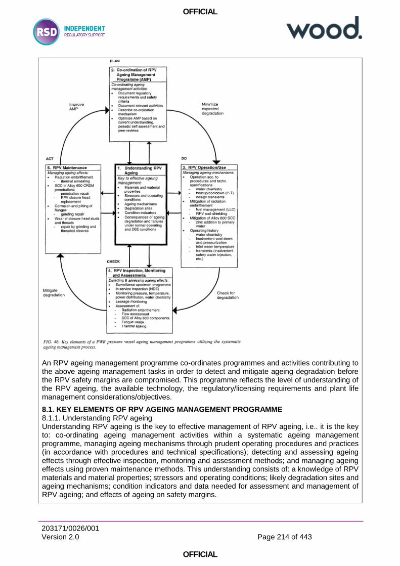
OFFICIAL
203171/0026/001 Version 2.0
Page 214 of 443
OFFICIAL
An RPV ageing management programme co-ordinates programmes and activities contributing to the above ageing management tasks in order to detect and mitigate ageing degradation before the RPV safety margins are compromised. This programme reflects the level of understanding of the RPV ageing, the available technology, the regulatory/licensing requirements and plant life management considerations/objectives.
8.1. KEY ELEMENTS OF RPV AGEING MANAGEMENT PROGRAMME 8.1.1. Understanding RPV ageing Understanding RPV ageing is the key to effective management of RPV ageing, i.e.. it is the key to: co-ordinating ageing management activities within a systematic ageing management programme, managing ageing mechanisms through prudent operating procedures and practices (in accordance with procedures and technical specifications); detecting and assessing ageing effects through effective inspection, monitoring and assessment methods; and managing ageing effects using proven maintenance methods. This understanding consists of: a knowledge of RPV materials and material properties; stressors and operating conditions; likely degradation sites and ageing mechanisms; condition indicators and data needed for assessment and management of RPV ageing; and effects of ageing on safety margins.
OFFICIAL
203171/0026/001 Version 2.0
Page 215 of 443
OFFICIAL
The understanding of RPV ageing is derived from the RPV baseline data, the operating and maintenance histories, and external experiences. This understanding should be updated on an ongoing basis to provide a sound basis for the improvement of the ageing management programme consistent with operating, inspection, monitoring, assessment and maintenance methods and practices.
The RPV baseline data consists of the performance requirements, the design basis (including codes, standards, regulator}' requirements), the original design, the manufacturer's data (including materials data) and the commissioning data (including inaugural inspection data). The RPV operating history includes the pressure-temperature records, system chemistry records, records on material radiation embrittlement from the surveillance programme and the ISI results.
8.1.3. RPV operation NPP operation has a significant influence on the rate of degradation of plant systems, structures and components. Exposure of RPV to operating conditions (e.g. temperature, pressure, fast neutron dose rate, water chemistry) outside prescribed operational limits could lead to accelerated ageing and premature degradation. Since operating practices influence RPV operating conditions, NPP operations staff have an important role within the ageing management program to minimize age related degradation of the RPV. They can do this by maintaining operating conditions within operational limits that are prescribed to avoid accelerated ageing of RPV components during operation. Examples of such operating practices are:
• fuel loading scheme to control the rate of radiation embrittlement; • operation within the prescribed pressure and temperature range during startup and shutdown
to avoid the risk of overpressure (this risk varies, depending on the fracture toughness) of the material;
• defining appropriate operator actions for the case of a possible PTS event to avoid critical transients;
• performing maintenance according to procedures designed to avoid contamination of RPV components with boric acid or other reagents containing halogens;
• on-line monitoring and record keeping of operational data necessary for predicting ageing degradation and defining appropriate ageing management actions.
Operation and maintenance in accordance with procedures of plant systems that influence RPV operational conditions (not only the primary system but also the auxiliary systems like water purification and injection systems), including the testing of the RPV and its components, and record keeping of operational data (incl. transients) are essential for an effective ageing management of the RPV and a possible plant life extension.
8.1.4. RPV inspection, monitoring and assessment Inspection and monitoring The RPV inspection and monitoring activities are designed to detect and characterize significant component degradation before the RPV safety margins are compromised. Together with an understanding of the RPV ageing degradation, the results of the RPV inspections provide a basis for decisions regarding the type and timing of maintenance actions and decisions regarding changes in operating conditions to manage detected ageing effects.
Inspection and monitoring of RPV degradation falls in two categories: (1) inservice inspection and surveillance capsule testing, and (2) monitoring of pressures and temperatures, water chemistry, transients (relative to fatigue), RPV leakage and power distributions.
Results of the ISI are used for flaw tolerance assessments while the surveillance capsule test results are used as input for the assessment of the radiation embrittlement.
Integrity assessment
OFFICIAL
203171/0026/001 Version 2.0
Page 216 of 443
OFFICIAL
An integrity assessment is used to assess the capability of the RPV to perform the required safety function, within the specified margins of safety, during the entire operating interval until the next scheduled inspection.
Integrity assessments have used a variety of methods in response to the particular conditions and circumstances present at the time of the assessment. Section 6 of this report describes the assessment methods used. Included in the RPV integrity assessments are radiation damage trend curves for comparison with surveillance capsule test results to assess radiation embrittlement and utilization of the ISI results along with fatigue crack growth models and fracture mechanics technologies to assess the flaw tolerance of the RPV. In addition to the integrity assessment relating to the RPV safety function, assessments are required of other ageing related degradations that may have an economic impact on the ageing management programme. These include assessment of the fatigue usage factors utilizing information/data from the on-line transient monitoring system, assessments of the stress corrosion cracking susceptibility of the Alloy 600 components and thermal ageing assessments.
RPV Maintenance ….Wear of the closure head studs and threads is also occasionally observed. The degradation of the closure studs and threads by wear requires that the closure holes be machined out and new threaded sleeves be inserted into the stud holes. The maintenance of the closure head studs and threads should be scheduled based on previous inspections for wear.
8.2.4. Fatigue The assessment in the ageing management programme of fatigue crack initiation caused by cyclic loadings should be carried out by either the use of delta stress (S) versus number of cycles (N) curves given in the ASME Section En B3000 rules or similar curves in the given country's code or regulatory rules. If a flaw is detected during ISI, fatigue crack growth analyses must also be performed as discussed below. Also, removal of the flaw with a boat sample and microstructural analysis should be considered.
(a) Analytical method — Miner's Rule is an analytical method which can be used to assess the possibility of fatigue crack initiation in RPVs. ASME Section EH, NB- 3222.4, specifies the use of Miner's Rule for calculating fatigue damage in structural components, as do the codes in a number of other countries. The use of Miner's Rule requires that the cyclic stresses and the number of cycles are known. The cyclic stresses and number of cycles are given in the RPV stress report. These values are determined from the NSSS vendor estimate of the type and number of transients. Use of Miner's Rule results in the determination of a cumulative usage factor, U, which is the total number of expected cycles at a given stress level divided by the allowable number of cycles at that stress level. The allowable number of cycles at any stress level can be determined from the stress versus number of cycles (S/N) design curve for the material of interest in the code. When more than one stress level is expected (which is usually the case), the cumulative usage factor is the summation of the ratio at each stress level. The cumulative usage factor shall not exceed 1.0 for any part of the RPV, and cumulative usage factors should be calculated for all the key components of the RPV including the closure head, nozzles, penetrations, studs and beltline region.
(b) Transient monitoring — The NSSS vendors' input to the stress report as to the number and type of transients can be overly conservative. Transient monitoring can be used to obtain more accurate estimates of both the total number of cycles and the stress ranges. For RPVs that went into operation prior to installing a transient monitoring system, a review of past operating records must be made to determine the number and type of transients prior to the installation of the monitors. Transient monitoring systems are a very valuable tool in determining the life of a RPV and should be part of the ageing management programme.
(c) Evaluation of ISI results — As discussed in Sections 3, 5 and 6 of this report, each country has specific ISI requirements. If a flaw is detected in the RPV during ISI and if the size of the flaw requires that a fracture mechanics analysis be performed to demonstrate the integrity of the component, then a fatigue analysis must also be performed. The fatigue analysis
OFFICIAL
203171/0026/001 Version 2.0
Page 217 of 443
OFFICIAL
considers the growth of the flaw or crack in fracture mechanics terms using a correlation between the cyclic crack growth rate, da/dK and the stress intensity range, AK. The growth of the flaw can be determined using the methodology given in Appendix A to ASME Section XI, or similar methodology. Flaw Evaluation Handbooks can be obtained from the NSSS vendors that can be used as a plant specific tool to assess the growth of a flaw over the design life of the RPV, as well as to determine the critical flaw size for instability. The ageing management programme should include either a Flaw Evaluation Handbook or be prepared to perform a fracture mechanics analysis if and when a flaw is detected during ISI.
(d) Microstructural analysis of a flaw — If a flaw is detected during ISI, consideration should be given to removing the flaw by taking a boat sample that contains the flaw and performing a microstructural analysis to determine if striations are evident on the surface of the flaw. Striations on the surface of a flaw means that the initiation of the flaw or growth was due to fatigue. If it is determined that a flaw was initiated by fatigue, then one should question the fatigue analysis performed prior to service. Removal of a flaw following ISI is not normally performed once a NPP has gone into operation because Code or Regulatory approved fracture mechanics methodologies are available to assess the growth and critical size of flaws. However, the ageing management programme should consider removal and metallographic evaluation as an option.
8.2.5. Wear
Degradation due to wear may occur during maintenance operations concerned with opening and closing of the RPV head. Wear can occur in the filets of the RPV bolts (studs). And, the RPV O-ring and the surfaces of the RPV flanges may also be degraded or damaged during the opening and closing operations. The RPV bolts (studs), the surface of the flanges and the O-ring should be inspected for evidence of degradation or wear. In addition, the outside of the RPV should be visually inspected for evidence of corrosion due to leakage from the head bolts or studs, a damaged O-Ring or scared flanges. Visual inspection of components of the RPV that may be subjected to wear should be part of the ageing management programme.
Key Themes: IAEA-TECDOC-1556 review global practice for the design, assessment, substantiation, inspection and management of PWR RPVs, of which closure studs are key component in their contribution to safety.
The objective of this report is to document the current practices for the assessment and management of the ageing of NPP RPVs. The report emphasizes safety aspects and also provides information on current inspection, monitoring and maintenance practices for managing ageing of RPVs
OFFICIAL
203171/0026/001 Version 2.0
Page 218 of 443
OFFICIAL
Reference: E2
Document Title/Version Number: IAEA. Assessment and management of ageing of major nuclear power plant components important to safety: BWR pressure vessels. IAEA-TECDOC-1470
Date of Issue: 2005
Document Review Status:
Document Scope: This report provides the technical basis for understanding and managing the ageing of the BWR RPV to ensure that the acceptable safety and operational margins are maintained throughout the plant service life. The scope of the report includes the following RPV components; vessel shell and flanges, structural weldments, closure studs, nozzles, penetrations and top and bottom heads. The scope of this report does not treat RPV internals, the control rod drive mechanisms (CRD), or the primary boundary piping used in BWRs. The pressurized water reactor (PWR) reactor vessels and Canadian deuteriumuranium (CANDU) pressure tubes and calandria are covered in separate companion reports.
Summary: The designs, materials of construction and physical features of the various BWR reactor pressure vessels are described in Section 2. The codes, regulations and guides used in a number of countries to design RPVs are summarized in Section 3. Section 4 presents the ageing
mechanisms, susceptible degradation sites, their significance and operating experience. Section 5 addresses the application of various inspection, monitoring and maintenance technologies. Section 6 gives the current practices and data required in assessing degradation of an RPV. Section 7 describes methods used to mitigate stress corrosion cracking. This report concludes, in Section 8, with a description of a systematic ageing management programme for BWR RPVs.
Key Requirements: Regulations and practices of safety and ageing management of RPVs in different countries generally show some differences. This applies for the design codes and ISI codes as well as the approach to life extension regulation.
Most countries adopted an approach for design and ISI regulation at least very similar to the ASME Code in the United States of America. Therefore, this report reflects mostly the approaches used in the USA. Wherever distinct differences are applicable in other countries, extra sub-chapters are introduced to explain the specific national regulation or approach.
The BWR reactor pressure vessel is the most important pressure boundary component of the nuclear steam supply system (NSSS) because its function is to contain the nuclear core under elevated pressures and temperatures. Additional RPV functions are to provide structural support for the reactor pressure vessel internals and the core.
Design analysis of ABB RPVs is done according to the ASME Code Section III NB-3000. Fatigue analysis is performed in accordance with ASME section III section NB-3216.2.
2.1. RPV design features The BWR RPV is comprised of a shell and a removable top head each with flanges which accommodate the head to flange bolting, closure studs, a bottom head which is welded to the shell, multiple nozzles and safe-ends, multiple penetrations and control rod drive stub tubes, a vessel support skirt and several attachment welds. Figure 2-1 (a) to (f) shows typical BWR RPVs.
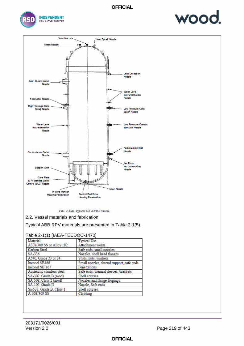
OFFICIAL
203171/0026/001 Version 2.0
Page 219 of 443
OFFICIAL
2.2. Vessel materials and fabrication
Typical ABB RPV materials are presented in Table 2-1(5). Table 2-1(1) [IAEA-TECDOC-1470]
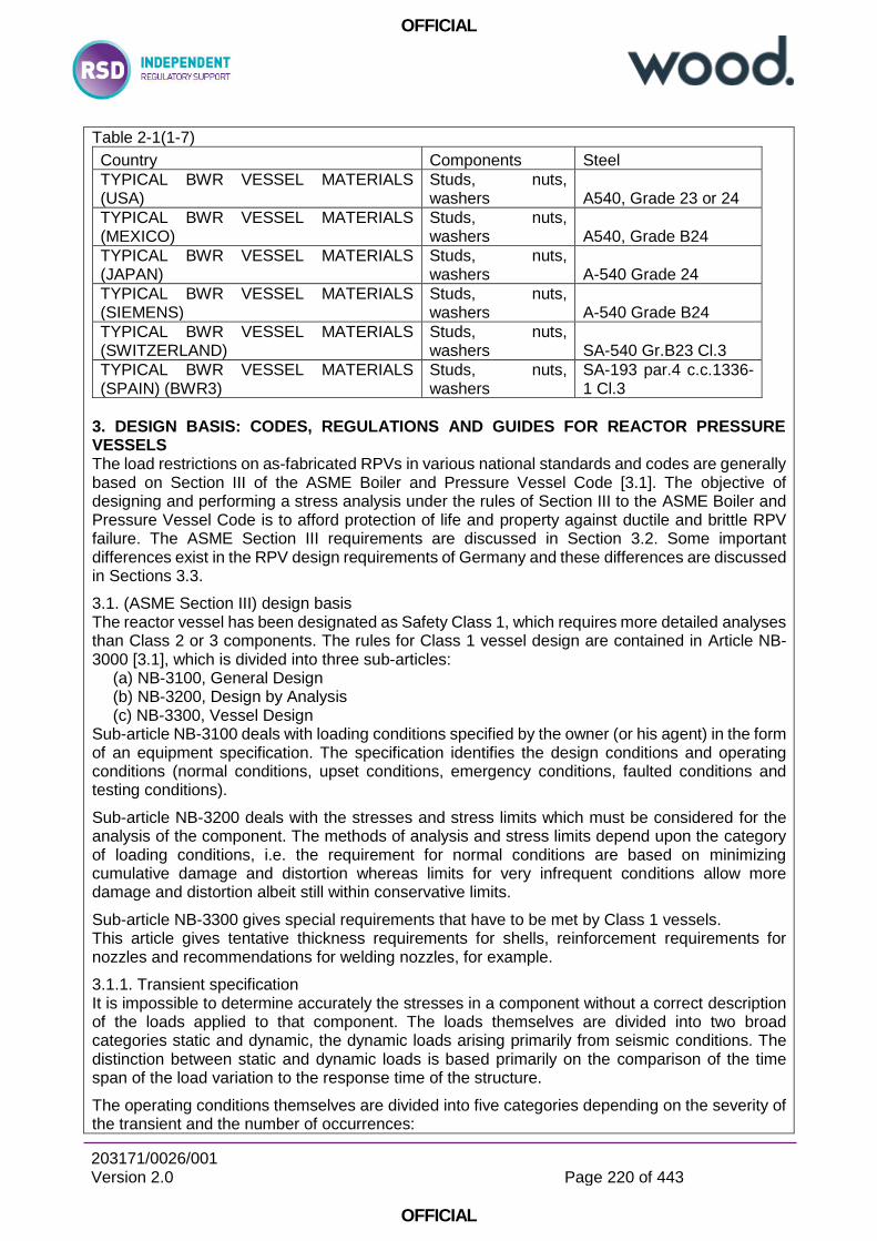
OFFICIAL
203171/0026/001 Version 2.0
Page 220 of 443
OFFICIAL
Table 2-1(1-7)
Country Components Steel
TYPICAL BWR VESSEL MATERIALS (USA)
Studs, nuts, washers A540, Grade 23 or 24
TYPICAL BWR VESSEL MATERIALS (MEXICO)
Studs, nuts, washers A540, Grade B24
TYPICAL BWR VESSEL MATERIALS (JAPAN)
Studs, nuts, washers A-540 Grade 24
TYPICAL BWR VESSEL MATERIALS (SIEMENS)
Studs, nuts, washers A-540 Grade B24
TYPICAL BWR VESSEL MATERIALS (SWITZERLAND)
Studs, nuts, washers SA-540 Gr.B23 Cl.3
TYPICAL BWR VESSEL MATERIALS (SPAIN) (BWR3)
Studs, nuts, washers
SA-193 par.4 c.c.1336-1 Cl.3
3. DESIGN BASIS: CODES, REGULATIONS AND GUIDES FOR REACTOR PRESSURE VESSELS The load restrictions on as-fabricated RPVs in various national standards and codes are generally based on Section III of the ASME Boiler and Pressure Vessel Code [3.1]. The objective of designing and performing a stress analysis under the rules of Section III to the ASME Boiler and Pressure Vessel Code is to afford protection of life and property against ductile and brittle RPV failure. The ASME Section III requirements are discussed in Section 3.2. Some important differences exist in the RPV design requirements of Germany and these differences are discussed in Sections 3.3.
3.1. (ASME Section III) design basis The reactor vessel has been designated as Safety Class 1, which requires more detailed analyses than Class 2 or 3 components. The rules for Class 1 vessel design are contained in Article NB-3000 [3.1], which is divided into three sub-articles:
(a) NB-3100, General Design (b) NB-3200, Design by Analysis (c) NB-3300, Vessel Design
Sub-article NB-3100 deals with loading conditions specified by the owner (or his agent) in the form of an equipment specification. The specification identifies the design conditions and operating conditions (normal conditions, upset conditions, emergency conditions, faulted conditions and testing conditions).
Sub-article NB-3200 deals with the stresses and stress limits which must be considered for the analysis of the component. The methods of analysis and stress limits depend upon the category of loading conditions, i.e. the requirement for normal conditions are based on minimizing cumulative damage and distortion whereas limits for very infrequent conditions allow more damage and distortion albeit still within conservative limits.
Sub-article NB-3300 gives special requirements that have to be met by Class 1 vessels. This article gives tentative thickness requirements for shells, reinforcement requirements for nozzles and recommendations for welding nozzles, for example.
3.1.1. Transient specification It is impossible to determine accurately the stresses in a component without a correct description of the loads applied to that component. The loads themselves are divided into two broad categories static and dynamic, the dynamic loads arising primarily from seismic conditions. The distinction between static and dynamic loads is based primarily on the comparison of the time span of the load variation to the response time of the structure.
The operating conditions themselves are divided into five categories depending on the severity of the transient and the number of occurrences:
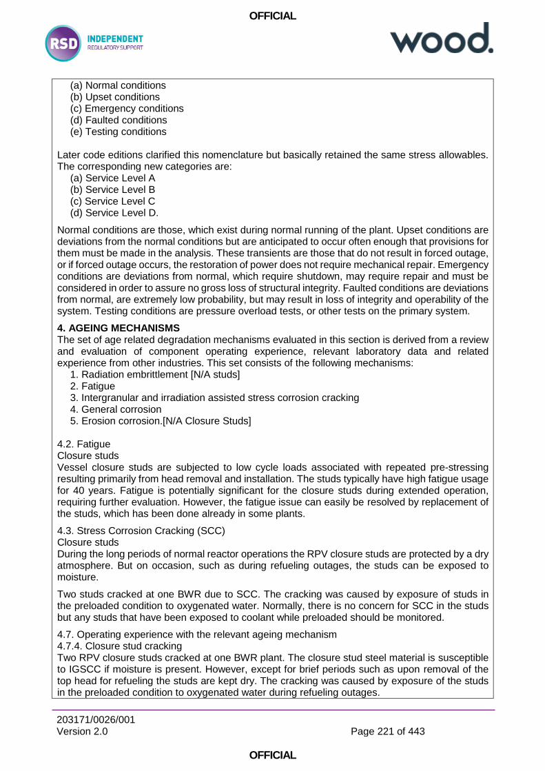
OFFICIAL
203171/0026/001 Version 2.0
Page 221 of 443
OFFICIAL
(a) Normal conditions (b) Upset conditions (c) Emergency conditions (d) Faulted conditions (e) Testing conditions
Later code editions clarified this nomenclature but basically retained the same stress allowables. The corresponding new categories are:
(a) Service Level A (b) Service Level B (c) Service Level C (d) Service Level D.
Normal conditions are those, which exist during normal running of the plant. Upset conditions are deviations from the normal conditions but are anticipated to occur often enough that provisions for them must be made in the analysis. These transients are those that do not result in forced outage, or if forced outage occurs, the restoration of power does not require mechanical repair. Emergency conditions are deviations from normal, which require shutdown, may require repair and must be considered in order to assure no gross loss of structural integrity. Faulted conditions are deviations from normal, are extremely low probability, but may result in loss of integrity and operability of the system. Testing conditions are pressure overload tests, or other tests on the primary system.
4. AGEING MECHANISMS The set of age related degradation mechanisms evaluated in this section is derived from a review and evaluation of component operating experience, relevant laboratory data and related experience from other industries. This set consists of the following mechanisms:
1. Radiation embrittlement [N/A studs] 2. Fatigue 3. Intergranular and irradiation assisted stress corrosion cracking 4. General corrosion 5. Erosion corrosion.[N/A Closure Studs]
4.2. Fatigue Closure studs Vessel closure studs are subjected to low cycle loads associated with repeated pre-stressing resulting primarily from head removal and installation. The studs typically have high fatigue usage for 40 years. Fatigue is potentially significant for the closure studs during extended operation, requiring further evaluation. However, the fatigue issue can easily be resolved by replacement of the studs, which has been done already in some plants.
4.3. Stress Corrosion Cracking (SCC) Closure studs During the long periods of normal reactor operations the RPV closure studs are protected by a dry atmosphere. But on occasion, such as during refueling outages, the studs can be exposed to moisture.
Two studs cracked at one BWR due to SCC. The cracking was caused by exposure of studs in the preloaded condition to oxygenated water. Normally, there is no concern for SCC in the studs but any studs that have been exposed to coolant while preloaded should be monitored.
4.7. Operating experience with the relevant ageing mechanism 4.7.4. Closure stud cracking Two RPV closure studs cracked at one BWR plant. The closure stud steel material is susceptible to IGSCC if moisture is present. However, except for brief periods such as upon removal of the top head for refueling the studs are kept dry. The cracking was caused by exposure of the studs in the preloaded condition to oxygenated water during refueling outages.
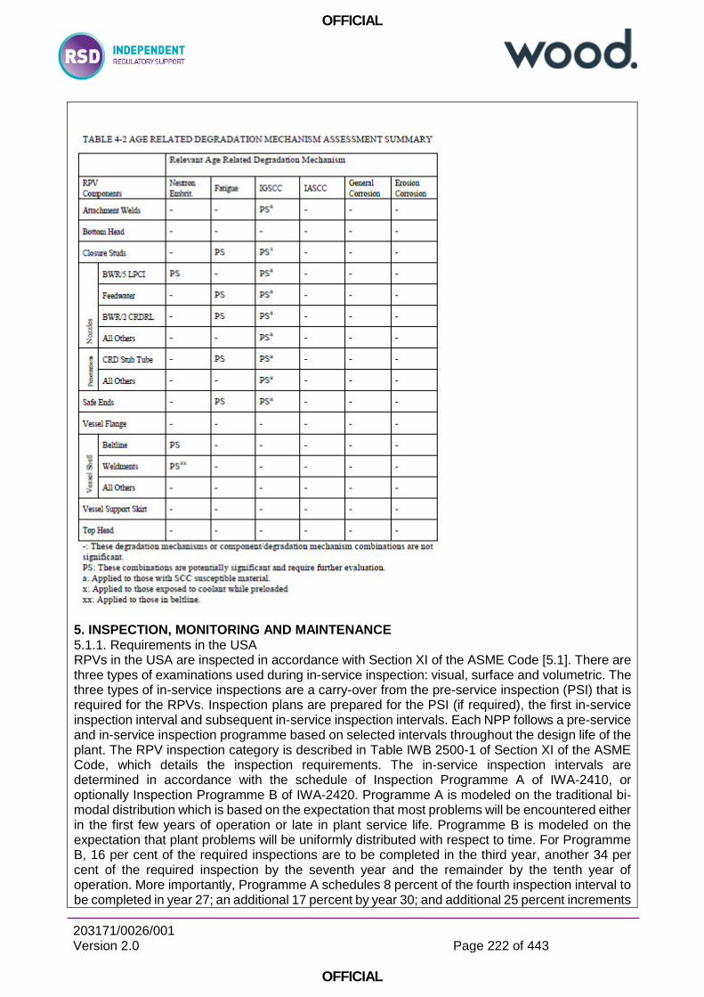
OFFICIAL
203171/0026/001 Version 2.0
Page 222 of 443
OFFICIAL
5. INSPECTION, MONITORING AND MAINTENANCE 5.1.1. Requirements in the USA RPVs in the USA are inspected in accordance with Section XI of the ASME Code [5.1]. There are three types of examinations used during in-service inspection: visual, surface and volumetric. The three types of in-service inspections are a carry-over from the pre-service inspection (PSI) that is required for the RPVs. Inspection plans are prepared for the PSI (if required), the first in-service inspection interval and subsequent in-service inspection intervals. Each NPP follows a pre-service and in-service inspection programme based on selected intervals throughout the design life of the plant. The RPV inspection category is described in Table IWB 2500-1 of Section XI of the ASME Code, which details the inspection requirements. The in-service inspection intervals are determined in accordance with the schedule of Inspection Programme A of IWA-2410, or optionally Inspection Programme B of IWA-2420. Programme A is modeled on the traditional bi-modal distribution which is based on the expectation that most problems will be encountered either in the first few years of operation or late in plant service life. Programme B is modeled on the expectation that plant problems will be uniformly distributed with respect to time. For Programme B, 16 per cent of the required inspections are to be completed in the third year, another 34 per cent of the required inspection by the seventh year and the remainder by the tenth year of operation. More importantly, Programme A schedules 8 percent of the fourth inspection interval to be completed in year 27; an additional 17 percent by year 30; and additional 25 percent increments
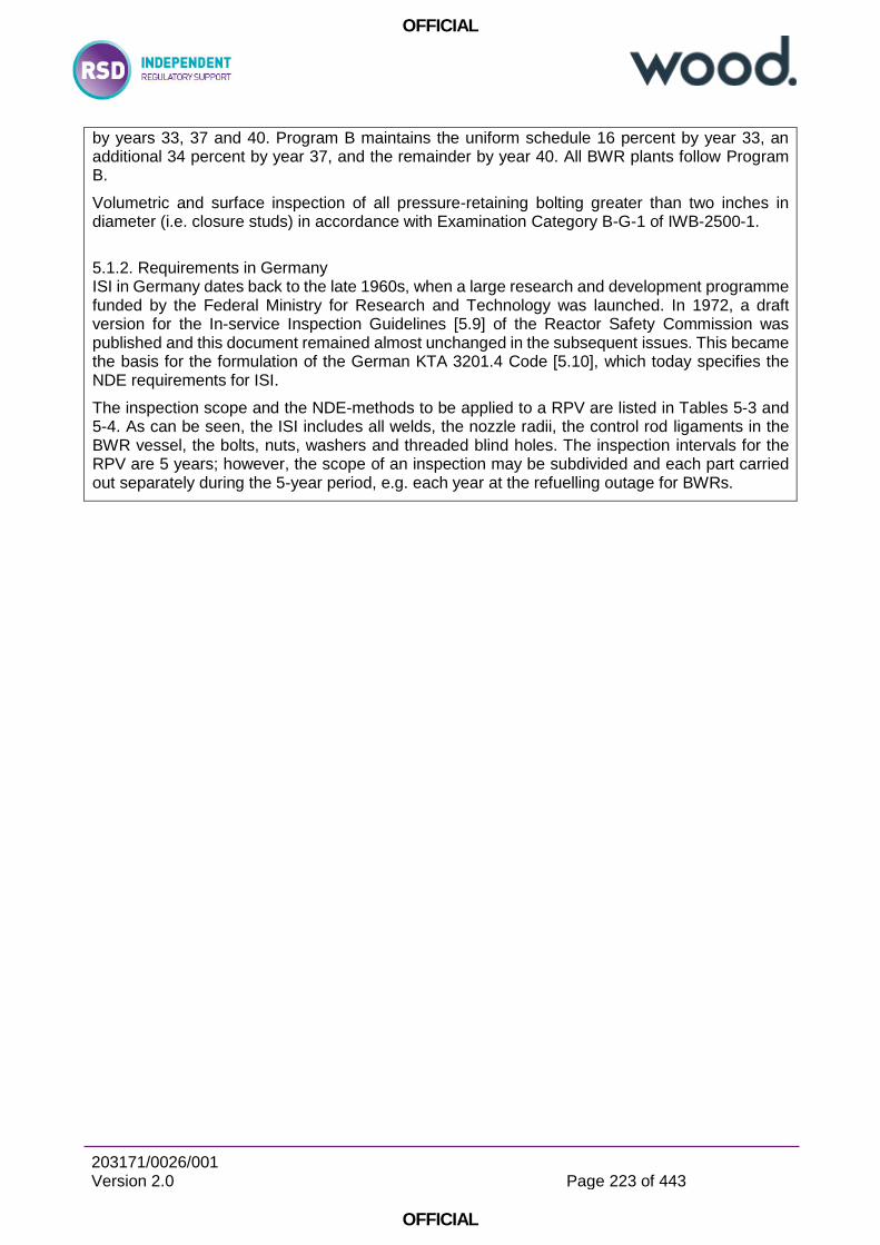
OFFICIAL
203171/0026/001 Version 2.0
Page 223 of 443
OFFICIAL
by years 33, 37 and 40. Program B maintains the uniform schedule 16 percent by year 33, an additional 34 percent by year 37, and the remainder by year 40. All BWR plants follow Program B.
Volumetric and surface inspection of all pressure-retaining bolting greater than two inches in diameter (i.e. closure studs) in accordance with Examination Category B-G-1 of IWB-2500-1.
5.1.2. Requirements in Germany ISI in Germany dates back to the late 1960s, when a large research and development programme funded by the Federal Ministry for Research and Technology was launched. In 1972, a draft version for the In-service Inspection Guidelines [5.9] of the Reactor Safety Commission was published and this document remained almost unchanged in the subsequent issues. This became the basis for the formulation of the German KTA 3201.4 Code [5.10], which today specifies the NDE requirements for ISI.
The inspection scope and the NDE-methods to be applied to a RPV are listed in Tables 5-3 and 5-4. As can be seen, the ISI includes all welds, the nozzle radii, the control rod ligaments in the BWR vessel, the bolts, nuts, washers and threaded blind holes. The inspection intervals for the RPV are 5 years; however, the scope of an inspection may be subdivided and each part carried out separately during the 5-year period, e.g. each year at the refuelling outage for BWRs.
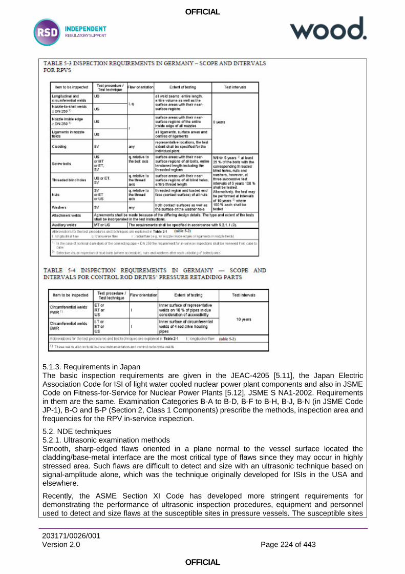
OFFICIAL
203171/0026/001 Version 2.0
Page 224 of 443
OFFICIAL
5.1.3. Requirements in Japan The basic inspection requirements are given in the JEAC-4205 [5.11], the Japan Electric Association Code for ISI of light water cooled nuclear power plant components and also in JSME Code on Fitness-for-Service for Nuclear Power Plants [5.12], JSME S NA1-2002. Requirements in them are the same. Examination Categories B-A to B-D, B-F to B-H, B-J, B-N (in JSME Code JP-1), B-O and B-P (Section 2, Class 1 Components) prescribe the methods, inspection area and frequencies for the RPV in-service inspection.
5.2. NDE techniques 5.2.1. Ultrasonic examination methods Smooth, sharp-edged flaws oriented in a plane normal to the vessel surface located the cladding/base-metal interface are the most critical type of flaws since they may occur in highly stressed area. Such flaws are difficult to detect and size with an ultrasonic technique based on signal-amplitude alone, which was the technique originally developed for ISIs in the USA and elsewhere.
Recently, the ASME Section XI Code has developed more stringent requirements for demonstrating the performance of ultrasonic inspection procedures, equipment and personnel used to detect and size flaws at the susceptible sites in pressure vessels. The susceptible sites
OFFICIAL
203171/0026/001 Version 2.0
Page 225 of 443
OFFICIAL
include the clad-base metal interface, nozzle inside radius section, reactor vessel structural welds, nozzle-to-vessel welds and bolts and studs. These requirements are needed to ensure that inspectors apply the appropriate ultrasonic inspection techniques in the field to correctly characterize the flaws at the susceptible sites in the vessel.
5.2.3. Visual inspection Visual inspection requirements are specified in ASME Section XI, IWB-2500. Table IWB-2500-1 specifies the components for which visual examinations are permitted. In some cases, these inspection requirements have been supplemented in the U.S. by BWRVIP guidelines. These supplemental inspections are necessary for detection of IGSCC.
Visual inspection methods contained in the ASME Code are VT-1, VT-2 and VT-3. For detection of IGSCC, the BWRVIP recommends the use of an enhanced visual technique. Definitions of these visual methods are discussed below.
• ASME VT-1: a visual inspection method capable of achieving 1/32 inch (0.79 mm) resolution. VT-1 is conducted to detect discontinuities and imperfections on the surface of components, including such conditions as cracks, wear, corrosion, or erosion. • ASME VT-2: a visual inspection method capable of detecting evidence of leakage from a pressure retaining component, with or without leakage collection systems, as required by the system pressure test. • ASME VT-3: a visual inspection method for assessing the general mechanical and structural condition of components and their supports. Parameters such as clearances, settings, and physical displacements must be verified to detect discontinuities and imperfections such as loss of integrity at bolted or welded connections, loose or missing parts, corrosion, wear, or erosion. • BWRVIP EVT-1: a visual inspection method capable of achieving ½ mil wire resolution. This technique is necessary for detection of IGSCC.
5.3. RPV material surveillance programmes 5.3.1. Requirements in the USA Every BWR pressure vessel operating in the western world has an ongoing RPV material radiation surveillance programme. To date, a large number of surveillance capsules have been removed from their host RPV and tested. The results of these specimen tests have been used to confirm the design predictions. In a BWR, the only concern relative to radiation embrittlement is the hydrostatic test temperature.
[Not normally applicable to Closure Studs]
5.4. Transient and fatigue cycle monitoring 5.4.1. Practice in the USA As discussed in Section 4.4, the only RPV components likely to experience significant fatigue damage are the RPV studs. In the worse case, the studs can be replaced, eliminating any concern. However, fatigue can become a significant degradation mechanism if indications or flaws are detected during the RPV in-service inspection or if consideration is given to extending the operating life of the plant. In the former case, fatigue crack growth becomes important in the assessment and management of the ageing of BWR RPVs. This is most likely a plant specific issue, since it is difficult to judge, in advance, where an indication might be detected.
5.4.2. Practice in Germany All German BWRs in operation are equipped with a fatigue monitoring system. On the basis of a plant specific weak point analysis of the NSSS, parameters to be monitored are defined and reported in a fatigue manual. Special emphasis is given to thermal loads such as thermal shocks, thermal stratification, and turbulent mixing phenomena, which may occur very locally. These transients have been measured by means of special purpose instrumentation (Thermocouples were installed on selected cross sections of interest). In addition, global parameters such as
OFFICIAL
203171/0026/001 Version 2.0
Page 226 of 443
OFFICIAL
internal pressure, fluid temperature, mass flow, water level, etc., have been measured via existing instrumentation and the data combined with the local parameters.
5.5. Current inspection, assessment and maintenance practices 5.5.2. Closure Studs: Fatigue/SCC Fatigue and SCC are significant degradation mechanisms for the closure studs. The circumstances of SCC caused stud failures, which occurred at a BWR/3 plant, are described in Section 4. Closure stud degradation due to both fatigue and SCC is addressed by current ASME code guidelines and GE RICSIL 055R1 [5.50], which responded to the closure stud cracking incidents, the effect of SCC of closure studs can be bounded within acceptable degradation limits and consequences of excessive degradation can be managed by inspection (ASME Section XI, GE RICSIL 055R1) and analytical evaluation. This management programme can be applied to all closure stud designs. The concern for fatigue/SCC of the studs is lessened by the fact that the studs are replaceable.
6. ASSESSMENT METHODS In this section component/age related degradation mechanism combinations found to require further evaluation are re-examined in terms of the capability of maintenance, in-service inspection, surveillance, testing and analytical assessment programmes to effectively manage potentially significant degradation effects. Degradation mechanism/component combinations for which generic program elements effectively manage the age-related degradation are considered to be adequately addressed.
Combinations of mechanisms and components for which generic effective programme elements cannot be shown to manage potentially significant age-related degradation require evaluation as discussed in the following sub-sections.
6.2. Fatigue assessment Evaluation of fatigue damage can be based either on the crack initiation stage or the crack propagation stage. The former is typified by the fatigue design procedures of the ASME Code Section III, Subsection NB-3200, while the latter is exemplified by the flaw evaluation/acceptance procedures of the ASME Code Section XI, Subsection IWB.
Environmental effects might be addressed in considering fatigue.
6.2.1. Crack initiation Crack initiation is estimated by determining the fatigue usage at a specific location that results from either actual or design-basis cyclic loads. The time-to-initiation can be predicted only if the applied load sequences and recurrence frequencies are known. If the cycling loading is random, estimates of time to initiation have to be treated with caution.
For fatigue life evaluation, the data needed are the amplitude and number of stress cycles experienced during a given operating period and the amplitude and number of cycles that lead to crack initiation. The sum of the ratios of these quantities gives the cumulative fatigue usage factor. The best source of information for plants with less than five years of operation is the certified stress report and the design specification. The certified stress report gives the design-basis cumulative usage factors for vessel components and the Code allowable number of cycles for anticipated events.
The fatigue usage factor is defined according to ASME Code requirements. This value must not exceed 1.0 during the design life of the component. With the conservatisms inherent to this calculation, it is presumed that fatigue crack initiation can be prevented by ensuring that the fatigue usage factors remain below the limit of 1.0. The ASME Code fatigue design curves are based on smooth-bar laboratory test data in air. The ASME Code applies a factor of 2 on strain range and a factor of 20 on the number of cycles to the smooth-bar data. The factor of 20 on cycles accounts for data scatter, size effect, surface finish and moderate environmental effects.
6.2.2. Cyclic crack growth

OFFICIAL
203171/0026/001 Version 2.0
Page 227 of 443
OFFICIAL
Once a crack has initiated, either by fatigue or some other mechanism such as SCC, continued application of cyclic stresses can produce subcritical crack growth. The Paris crack growth relationship [6.20] is generally used to calculate crack growth:
6.2.3. Time-dependent cyclic crack growth
The time dependent crack growth resulting from cyclic loading can be determined by:
6.2.4. Fatigue damage management programs It is recommended that the fatigue usage is monitored for critical parts. For long term operation the following criteria should be met (see also 6.2.6):
(1) For plants with an ASME section III design basis, the expected transients for long term operation must fall within the original design basis by cycle counting or the analysis should be refined; (2) The Section III, Subsection NB evaluation procedures remain valid for these calculations.
For component locations and parts with a history of fatigue damage or as an alternative to the analytical verification of the adequacy of the original fatigue design basis throughout the extended operation, an effective programme for managing the effects of potentially significant fatigue damage in components is adherence to ASME Section XI procedures. Formal in-service examination requirements are provided for each plant in its plant In-service Inspection (ISI) and In-service Testing (IST) programmes and are referenced to an applicable edition of the ASME Code Section XI Rules for In-service Inspection of Nuclear Power Plant Components. The plant in-service inspection programme, including any commitments to enhanced or augmented inspections as the result of plant operating experience or regulatory enforcement, provides an acceptable basis for continued operation of the component with indications that are within established limits. The intervals for these examinations, and the requirements for expansion of the number of locations examined if flaws are detected, assure that significant undetected fatigue degradation of components will not occur.
6.2.5. Fatigue reanalysis If the confirmation of the current fatigue design basis for the extended operation is to be demonstrated, the procedure to be followed is similar to that used during the initial plant design. During the design of plant components in accordance with NB-3000, a set of design-basis transients was defined. These design-basis transients, as described by temperature, pressure, flow rate, and number of occurrences, were intended to conservatively represent all transients expected during the design life of the plant.
6.2.6. In-service examination For component locations and parts having a history of fatigue damage, or as an alternative to analytical verification of the adequacy of the fatigue design basis throughout the extended operation, potentially significant fatigue damage can be managed through a programme of periodic in-service examinations. It will be necessary to supplement the measurements with analysis to assure operating margins. These examinations should be directed toward the detecting and characterizing fatigue crack initiation and growth to assure that the detected and sized
OFFICIAL
203171/0026/001 Version 2.0
Page 228 of 443
OFFICIAL
indications do not compromise component structural integrity during the period intervening between examinations.
6.2.7. Fatigue assessment methods in Germany The procedure as described in the ASME Code for the assessment of crack initiation and cyclic crack growth is basis for the relevant stipulations in the German KTA 3201.2.
6.2.8. Fatigue assessment methods in Japan General requirement The fatigue evaluation method and (S,N) fatigue curves stipulated in the METI notification No.501 [6.22] and JSME Code and Standards “Code for Design and Construction”, JSME SNA2-2002 [6.23] are similar to the ASME Section III B3000 rules.
Environmental fatigue evaluation In September 2000, Japanese regulatory body, MITI (current METI), published a notification, which required electric utilities to perform fatigue evaluation for the plant life management evaluation taking into account environmental effect. It was attached to the notification. The parameter for evaluating environmental effects is the fatigue life reduction factor for environmental effects, Fen. Fen represents the reduction in fatigue life resulting from the high-temperature water LWR environment
6.3. Stress corrosion cracking assessment The technique used for determining SCC effects on component life is in-service inspection by volumetric means, such as ultrasonic imaging to detect and size flaws, and subsequent fracture mechanics evaluation to predict life remaining after initiation of the detected flaw.
Analytical evaluation is a useful tool for dispositioning detected and sized flaws, this method most often used for component life prediction is crack growth assessment, using laboratory crack growth data and analytical fracture mechanics stress intensity calculations.
SCC crack growth rates under various environmental conditions have been generated for the austenitic steels used for internals.
7. MITIGATION TECHNOLOGIES This section addresses mitigation methods for SCC since SCC is the prevalent degradation mode for RPV. Mitigation methods for other known sources of degradation (e.g. fatigue and thermal) are not addressed.
IGSCC has been a concern in the BWR community since first detected in the late 1950’s in annealed stainless steel fuel cladding and in the mid-1960’s Type 304 stainless steel recirculation piping. In the late 1980’s IGSCC was detected in reactor internal components, i.e. shroud head bolts, core shrouds, access hole covers, etc. More recent experience from the world wide BWR fleet indicates that cracking of vessel internals has become more widespread than previously thought. For RPVs, parts like attachment welds, CRD stub tubes and safe ends have been subject to IGSCC.
8. REACTOR PRESSURE VESSEL AGEING MANAGEMENT PROGRAMME The primary age degradation mechanisms for the RPV are cracking due to fatigue and cracking due to IGSCC. Radiation embrittlement is not an issue other than its impact on the temperature at which the pre-start up leak test or periodic hydrotest is performed. Fatigue and SCC interacts with each other and both are impacted by water chemistry. The cracking resulting from either cause can impair the safety functions of the RPV. Also both mechanisms are affected by time. For these reasons a systematic RPV ageing management is needed.
[Essentially as per IAEA. Assessment and Management of Ageing of Major Nuclear Power Plant Components Important to Safety: PWR Pressure Vessels 2007 Update. IAEA-TECDOC-1556.]
OFFICIAL
203171/0026/001 Version 2.0
Page 229 of 443
OFFICIAL
Key Themes: IAEA-TECDOC-1470 provides RGP for the complete lifecycle for Closure Bolts as used in BWR type reactors. Compliance, with consideration to any emergent factors since the time of writing would create a strong safety case.
OFFICIAL
203171/0026/001 Version 2.0
Page 230 of 279
OFFICIAL
6.6 Reviews of UK Code and Standards Requirements
6.7 Reviews of Relevant UK and International Nuclear RGP
Sections 6.6. and 6.7 contain information from proprietary codes and standards and have been removed for copyright reasons. The original documents reviewed are included in the list of references at Section 7.
OFFICIAL
203171/0026/001 Version 2.0
Page 440 of 443
OFFICIAL
7 References
7.1 General References
1. ONR. Events reported to the Nuclear Safety Regulator in the period of 1 April 2001 to 31 March 2015
7.2 IAEA Safety Standards and Regulations
A1. IAEA Safety Standards. Fundamental Safety Principles. Safety Fundamental No. SF-1 (2006)
A2. IAEA Safety Standards. Governmental, Legal and Regulatory Framework for Safety. General Safety Requirements No. GSR Part 1 (Rev. 1)
A3. IAEA Safety Standards. Leadership and Management for Safety. General Safety Requirements No. GSR Part 2 (Rev. 1)
A4. IAEA Safety Standards. Radiation Protection and Safety of Radiation Sources: International Basic Safety Standards Part 3. General Safety Requirements No. GSR Part 3.
A5. IAEA Safety Standards. Safety Assessment for Facilities and Activities. General Safety Requirements No. GSR Part 4 (Rev. 1)
A6. IAEA Safety Standards. Safety of Nuclear Power Plants: Design. Specific Safety Requirements No. SSR-2/1 (Rev. 1)
A7. IAEA Safety Standards. Safety of Nuclear Power Plants: Commission and Operation. Specific Safety Requirements No. SSR-2/2 (Rev. 1)
A8. IAEA Safety Standards. Regulations for the Safe Transport of Radioactive Material 2018 Edition. Specific Safety Requirements No. SSR-6 (Rev. 1)
7.3 UK Statute
B1. Energy Act 2013 B2. Health and Safety at Work ect. Act 1974 B3. The Ionising Radiations Regulations 2017 B4. Principles and guidelines to assist HSE in its judgements that duty-holders have reduced risk
as low as reasonably practicable (http://www.hse.gov.uk/risk/theory/alarp1.htm). B5. Assessing compliance with the law in individual cases and the use of good practice
(http://www.hse.gov.uk/risk/theory/alarp2.htm) B6. Policy and guidance on reducing risks as low as reasonably practicable in design
(http://www.hse.gov.uk/risk/theory/alarp3.htm) B7. HSE principles for Cost Benefit Analysis (CBA) in support of ALARP decisions
(http://www.hse.gov.uk/risk/theory/alarpcba.htm) B8. Cost Benefit Analysis (CBA) Checklist (http://www.hse.gov.uk/risk/theory/alarpcheck.htm) B9. ALARP "at a glance" (http://www.hse.gov.uk/risk/theory/alarpglance.htm) B10. The Carriage of Dangerous Goods and Use of Transportable Pressure Equipment
Regulations 2009. Statutory Instruments 2009 No. 1348 B11. Economic Commission for Europe Inland Transport Committee. ADR. European
Agreement Concerning the International Carriage of Dangerous Goods by Road Volume 1. ECE/TRANS/257 (Vol.I)
B12. Convention concerning International Carriage by Rail (COTIF) Appendix C – Regulations concerning the International Carriage of Dangerous Goods by Rail (RID). 2019
7.4 IAEA Guidance
C1. IAEA Safety Standards. Application of the Management System for Facilities and Activities. Safety Guide No. GS-G-3.1. 2006
C2. IAEA Safety Standards Series. The Management System for Nuclear Installations. Environment. Safety Guide No. GS-G-3.5
OFFICIAL
203171/0026/001 Version 2.0
Page 441 of 443
OFFICIAL
C3. IAEA Safety Standards Series. Design of Reactor Containment System for Nuclear Power Plants. Safety Guide No. NS-G-1.10. 2004
C4. IAEA Safety Standards Series. Deterministic Safety Analysis for Nuclear Power Plants. Specific Safety Guide No. SSG-2. 2009
C5. IAEA Safety Standards Series. Seismic Design and Qualification for Nuclear Power Plants. Safety Guide No. NS-G-1.6. 2003
C6. IAEA Draft Safety Guide. Advisory Material for the IAEA Regulations for the Safe Transport of Radioactive Material (2018 Draft). Specific Safety Guide No. SSG-26. 2018
C7. IAEA Safety Standards. Schedules of Provisions of the IAEA Regulations for the Safe Transport of Radioactive Material (2012 Edition). Specific Safety Guide No. SSG-33. 2012
C8. IAEA Safety Standards. Periodic Safety Review for Nuclear Power Plants. Specific Safety Guide No. SSG-25
7.5 ONR Guidance
D1. ONR. License condition handbook. February 2017 D2. ONR. Safety Assessment Principles for Nuclear Facilities. 2014 Edition Revision 0 D3. ONR Guide. Guidance on the Demonstration of ALARP (As Low As Reasonably Practicable).
Nuclear Safety Technical Assessment Guide NS-TAST-GD-005 Revision 9. March 2018 D4. ONR Guide. Examination, Inspection, Maintenance and Testing of Items Important to Safety.
Nuclear Safety Technical Assessment Guide NS-TAST-GD-009 Revision 5. May 2019 D5. ONR Guide. Integrity of Metal Structures, Systems and Components. Nuclear Safety
Technical Assessment Guide NS-TAST-GD-016 Revision 5. March 2017 D6. ONR Guide. The Purpose, Scope and Content of Safety Cases. Nuclear Safety Technical
Assessment Guide NS-TAST-GD-051 Revision 4. June 16 D7. ONR Guide. Human Factors Integration. Nuclear Safety Technical Assessment Guide NS-
TAST-GD-058 – Revision 3. March 2017 D8. ONR Guide. Nuclear Safety Technical Assessment Guide NS-TAST-GD-063 Revision 4.
October 2018 D9. ONR Guide. Categorisation of Safety Functions and Classification of Structures, Systems
and Components. Nuclear Safety Technical Assessment Guide NS-TAST-GD-094 Revision 0. November 2015
D10. ONR Guide. Transport Engineering Assessment . Nuclear Safety Technical Assessment Guide NS-TAST-GD-099 Revision 0. April 2017
D11. ONR Guide. GUIDANCE FOR APPLICATIONS FOR UK COMPETENT AUTHORITY APPROVAL (ONR Transport Permissioning - External Guidance) TRA-PER-GD-014 Revision 1. July 2016
D12. ONR Guide. ONR Transport Permissioning External Guidance (Special Arrangement Approvals) TRA-PER-GD-016 Revision 0. June 2016
D13. ONR Guide. General Guidance for Mechanical Engineering Specialism Group. Nuclear Safety Technical Assessment Guide NS-TAST-GD-102 Revision 0. January 2019
7.6 IAEA RGP
E1. IAEA. Assessment and Management of Ageing of Major Nuclear Power Plant Components Important to Safety: PWR Pressure Vessels 2007 Update. IAEA-TECDOC-1556
E2. IAEA. Assessment and management of ageing of major nuclear power plant components important to safety: BWR pressure vessels. IAEA-TECDOC-1470
7.7 Relevant UK Codes and Standards
7.7.1 Standards Applicable to Boiler Pressure Vessels
F1. ASME Boiler and Pressure Vessel Code. Subsection NCA General Requirements for Division 1 and Division 2. 2019
OFFICIAL
203171/0026/001 Version 2.0
Page 442 of 443
OFFICIAL
F2. ASME Boiler and Pressure Vessel Code. Section III Rules for Construction of Nuclear Facility Components Division 1 — Subsection NB Class 1 Components. 2019
F3. ASME Boiler and Pressure Vessel Code. Section III Rules for Construction of Nuclear Facility Components Division 1 — Subsection NC Class 2 Components. 2019
F4. ASME Boiler and Pressure Vessel Code. Section III Rules for Construction of Nuclear Facility Components Appendices. 2019
F5. ASME Boiler and Pressure Vessel Code. Section XI Rules for Construction of Nuclear Facility Components Division 1 Rules for Inspection and Testing of Components of Light-Water-Cooled Plants 2019
F6. ASME Boiler and Pressure Vessel Code. Section III Rules for Construction of Nuclear Facility Components Part D Properties (Metric). 2019
F7. ASME. Quality Assurance for Fasteners. ASME B18.18-2017
7.7.2 Standards Applicable to Steelwork / General Fabrication
F8. BRITISH STANDARD. Rules for the design of cranes — Part 1: Specification for classification, stress calculations and design criteria for structures. BS 2573-1:1983
F9. BRITISH STANDARD. Eurocode — Basis of structural design. BS EN 1990:2002 +A1:2005 Incorporating corrigenda December 2008 and April 2010
F10. BSI Standards Publication. Guide to fatigue design and assessment of steel products. BS 7608:2014+A1:2015
F11. BSI Standards Publication. Cranes - General Design. Part 3-1: Limit States and proof competence of steel structure. BS EN 13001-3-1:2012+A1:2013
F12. BRITISH STANDARD. Eurocode 3: Design of steel structures — Part 1-8: Design of joints. BS EN 1993-1-8:2005
F13. BRITISH STANDARD. Eurocode 3: Design of steel structures — Part 1-9: Fatigue. BS EN 1993-1-9:2005, Incorporating corrigenda December 2005, September 2006 and April 2009
F14. BSI Standards Publication. Execution of steel structures and aluminium structures Part 1: Requirements for conformity assessment of structural components BS EN 1090-1:2009+A1
F15. BSI Standards Publication. Execution of steel structures and aluminium structures
Part 2: Technical requirements for steel structures. BS EN 1090‑2:2018 F16. BSI Standards Publication. Execution of steel structures and aluminium structures
Part 3: Part 3: Technical requirements for aluminium structures. BS EN 1090‑3:2019 F17. BSI Standards Publication. High-strength structural bolting assemblies for preloading
Part 1: General requirements BS EN 14399-1:2015 F18. BSI Standards Publication. High-strength structural bolting assemblies for preloading
Part 2: Suitability for preloading BS EN 14399-2:2015 F19. BSI Standards Publication. High-strength structural bolting assemblies for preloading
Part 3: Part 3: System HR — Hexagon bolt and nut assemblies BS EN 14399-3:2015 F20. BSI Standards Publication. High-strength structural bolting assemblies for preloading
Part 5: Plain washers BS EN 14399-5:2015 F21. BSI Standards Publication. High-strength structural bolting assemblies for preloading
Part 6: Part 6: Plain chamfered washers BS EN 14399-6:2015 F22. BSI Standards Publication. High-strength structural bolting assemblies for preloading
Part 9: System HR or HV - Direct tension indicators for bolt and nut assemblies BS EN 14399-9:2018
F23. BSI Standards Publication. High-strength structural bolting assemblies for preloading Part 10: System HRC - Bolt and nut assemblies with calibrated preload BS EN 14399-10:2018
F24. BSI Standards Publication. Non-preloaded structural bolting assemblies Part 1: General requirements BS EN 15048-1:2016
OFFICIAL
203171/0026/001 Version 2.0
Page 443 of 443
OFFICIAL
F25. BSI Standards Publication. Non-preloaded structural bolting assemblies Part 2: Fitness for purpose. BS EN 15048-2:2016
F26. BSI Standards Publication. Fasteners — Prevailing torque steel nuts — Functional properties BS EN ISO 2320:2015
F27. BRITISH STANDARD Guide to design considerations on The strength of screw threads BS 3580:1964
F28. BRITISH STANDARD. Fasteners – Quality assurance System. BS EN ISO 16426:2002
7.8 Relevant UK and International Nuclear RGP
G1. TCSC 1006 Transport of Radioactive Material Code of Practice - Guide to the Securing/Retention of Radioactive Material Payloads and Packages During Transport. July 2018
G2. TCSC 31 Transport of Radioactive Material Code of Practice - Design and Operation to Minimise Seizure of Fasteners. June 2014
G3. TCSC 1079 Transport of Radioactive Material Code of Practice - Lifting Points for Radioactive Material Transport Packages Dec 2009
G4. TCSC 1086 Transport of Radioactive Material Code of Practice - Good Practice Guide to Drop Testing of Type B Transport Package
G5. TCSC 1087 Transport of Radioactive Material Code of Practice - The Application of Finite Element Analysis to Demonstrate Impact Performance of Transport Package Design March 2018
G6. ISO 10276 Nuclear energy — Fuel technology — Trunnions for packages used to transport radioactive material. Draft 2019
G7. U.S. Nuclear Regulatory Commission. Regulatory Guide. MATERIALS AND INSPECTIONS FOR REACTOR VESSEL CLOSURE STUDS. REGULATORY GUIDE 1.65 Revision 1 April 2010
G8. U.S. Nuclear Regulatory Commission. Bolting Applications. NUREG/CR-3604 BNL-NUREG-51735
G9. U.S. Nuclear Regulatory Commission. Stress Analysis of Closure Bolts for Shipping Casks. NUREG/CR-6007 BNL-NUREG-110637
G10. BAM. Guideline on the Assessment of the Lid Systems and Load Attachment Systems of Transport Packages for Radioactive Materials. BAM-GGR 012 Issue 2012-11
G11. SANDIA REPORT. Guideline for Bolted Joint Design and Analysis: Version 1.0. SAND2008-0371
7.9 Relevant General RGP and Smart Bolt Technologies
H1. CRC Press. Handbook of Bolted Joints, John H. Bickford. ISBN 0-8247-9977-1. 1998 H2. Transport Research laboratory. Heavy vehicle wheel detachment and possible solutions
Phase 2 – final report PPR475 2010