Embed Size (px)
Citation preview

OW
NE
R’S
MA
NU
AL Should the installer or owner be unfamiliar with the correct
installation or operation of this type of equipment you should contact the distributor/manufacturer for the correct advice before proceeding with the installation or operation of this product.
For the Installation, Operation and Service of
SilentFlo Pool Pump
The pump must be supplied from a circuitprotected by a residual current device (RCD) with
a maximum rated residual current of 30mA

Table of Contents Page Model Data 2Installation 3Pressure Testing 4Pump Mount 5Tefl on Taping Instructions 6Fittings 6Pool Outlets 6Entrapment Protection 7Testing and Certifi cation 7Outlets per Pump 7Water Velocity 7Electrical 8Operation 9Priming Pump 10Service and Maintenance 11Troubleshooting 12Parts Breakdown 14Warranty 15
1

2
Model Data
PartNumber
Output Power Max Total Head (m)(W) (hp)
SF550100 550 3/4 18
SF750103 750 1 17
SF1100100 1100 1.5 15
SF1500100 1500 2 12
Technical Information
Inlet (Suction): ABS Barrel Union to suit 50mm I.D PVC pipe to AS/NZS 1477
Outlet (Discharge): ABS Barrel Union to suit 50mm I.D PVC pipe to AS/NZS 1477
Max Working Pressure: 260 kPa
Water Temperature Range: 5°C – 38°C
IP Rating: IPX5
Electrical Rating: 230-240V 50Hz single phase
Motor: Built in auto reset overload protection. Flexible power supply cord 10Amp.
Recommended pH Range: 7.2 - 7.8 (Guide Only)
Maximum Ambient temperature: 55°C

3
Incorrectly installed or tested equipment may fail, causing severe injury or property damage.
Read the following instructions in this owner’s manual when installing and operating equipment. Have a trained pool professional perform all pressure tests.
1. Do not connect system to high pressure or mains water system.
2. Use equipment only in a swimming pool or spa pool installation.
3. Install pump with at least 2 hydraulically balanced main drains equipped with correctly installed, screw - fastened, antientrapment certifi ed covers according to local regulations.
4. Trapped air in system can cause explosion.Ensure all air is out of the system before operating or testing equipment.
Silentfl o is electrically connected. Ensure that it is isolated from electrical supply during installation and any subsequent service work.
The pump should be installed and serviced by a suitably qualifi ed person in order to avoid hazard.
These instructions are a guide only. Should you the installer or owner of the product be unfamiliar with the correct installation or operation of this product you should contact a suitably qualifed person for advice.
Freezing conditions will damage the unit, as water expands as it freezes. Ensure that Silentfl o is located so that it is not prone to freezing, or ensure that the product is disconnected and dried of water during cold conditions.
Installation
4
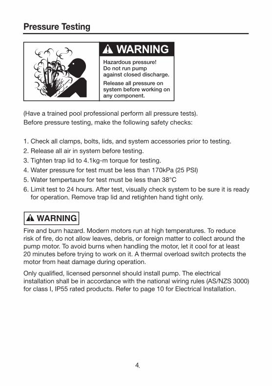
(Have a trained pool professional perform all pressure tests).Before pressure testing, make the following safety checks:
1. Check all clamps, bolts, lids, and system accessories prior to testing.
2. Release all air in system before testing.
3. Tighten trap lid to 4.1kg-m torque for testing.
4. Water pressure for test must be less than 170kPa (25 PSI)
5. Water tempertaure for test must be less than 38°C
6. Limit test to 24 hours. After test, visually check system to be sure it is ready for operation. Remove trap lid and retighten hand tight only.
Fire and burn hazard. Modern motors run at high temperatures. To reduce risk of fi re, do not allow leaves, debris, or foreign matter to collect around the pump motor. To avoid burns when handling the motor, let it cool for at least 20 minutes before trying to work on it. A thermal overload switch protects the motor from heat damage during operation.
Only qualifi ed, licensed personnel should install pump. The electrical installation shall be in accordance with the national wiring rules (AS/NZS 3000) for class I, IP55 rated products. Refer to page 10 for Electrical Installation.
Pressure Testing

Pump mount must:
1. Be located away from corrosive or fl ammable chemicals. Have enough ventilation to maintain air tempertaure at less than the maximum ambient temperture rating. If this pump is installed in an enclosure/pump house, the enclosure must have adequate ventilation (200sq.cm min, inlet & outlet) and air circulation to keep the temperature in the enclosure at or below the motor’s rated ambient temperature whenever the pump is running. Keep rear of motor clear (150mm).
2. Be solid, level, rigid and ribration free. (To reduce vibration and pipe stress, bolt pump to mount). Fixing holes accept 12mm fasteners.
3. Allow pump suction inlet height to be as far below water level as possible.
4. Allow use of short, direct suction pipe (to reduce friction losses).
5. Allow for shut-off valves in suction and discharge piping.
6. Have adequate fl oor drainage to prevent fl ooding.
7. Be protected from excess moisture
8. Allow adequate access for servicing pump and piping.
We recommend mounting the pump on a concrete platform for quietest performance.
Use Tefl on tape for making all threaded connections to the pump. DO NOT use pipe dope (glue) as this will cause stress fractures in the pump.
Pump suction and discharge connections have moulded in thread stops. DO NOT screw pipe in beyond these stops.
DO NOT use sealants which are incompatible with pipe fi ttings.
5
Pump Mount
Equipotential Bonding Terminal
Fixing Holes
6
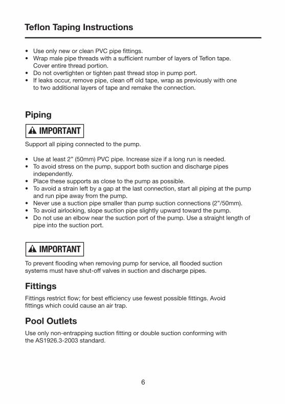
• Use only new or clean PVC pipe fi ttings.• Wrap male pipe threads with a suffi cient number of layers of Tefl on tape.
Cover entire thread portion.• Do not overtighten or tighten past thread stop in pump port.• If leaks occur, remove pipe, clean off old tape, wrap as previously with one
to two additional layers of tape and remake the connection.
Piping
Support all piping connected to the pump.
• Use at least 2” (50mm) PVC pipe. Increase size if a long run is needed.• To avoid stress on the pump, support both suction and discharge pipes
independently.• Place these supports as close to the pump as possible.• To avoid a strain left by a gap at the last connection, start all piping at the pump
and run pipe away from the pump.• Never use a suction pipe smaller than pump suction connections (2”/50mm).• To avoid airlocking, slope suction pipe slightly upward toward the pump.• Do not use an elbow near the suction port of the pump. Use a straight length of
pipe into the suction port.
To prevent fl ooding when removing pump for service, all fl ooded suctionsystems must have shut-off valves in suction and discharge pipes.
FittingsFittings restrict fl ow; for best effi ciency use fewest possible fi ttings. Avoidfi ttings which could cause an air trap.
Pool OutletsUse only non-entrapping suction fi tting or double suction conforming withthe AS1926.3-2003 standard.
Tefl on Taping Instructions

7
Pump suctions are hazardous and can trap and drown or disembowel bathers.Do not use or operate pump, pool or spa if a suction outlet cover is missing,broken, or loose. Follow the guidelines below for a pump installation whichminimises risk to users or pools and spas.
Entrapment ProtectionThe pump suction system must provide protection against hazard of suctionentrapment or hair entrapment/entanglement.
Testing and Certifi cationSuction outlet covers must have been tested by a nationally recognisedtesting laboratory and found to comply with the latest AS1926.3 standard orASME/ANSI specifi cation for Suction Fittings For Use in Swimming Pools,Spas, Hot Tubs, and Whirlpool Bathtub Applications.
Outlets Per PumpProvide at least two hydraulically balanced main drains, with covers, for eachswimming pool pump suction line. The centres of the main drains (suctionfi ttings) must be at least 800mm apart.The system must be built so that it cannot operate with the pump drawingwater from only one main drain (that is, there must be at least two main drainsconnected to the pump whenever it is running). However, if two main drainsrun into a single suction line, the single suction line may be equipped with avalve which will shut off both main drains from the pump.More than one pump can be connected to a single suction line as long as therequirements above are met.
Water VelocityThe maximum water velocity through any suction outlet must comply withthe latest AS1926.3 Standard or ASME/ANSI Specifi cation for SuctionFittings For Use in Swimming Pools, Spas, Hot Tubs, and Whirlpool BathtubApplications.

Hazardous voltage.Can shock, burn orcause death.
8
WARNING
ElectricalElectrical installation shall be in accordance with the national wiring rules (AS/NZS 3000) taking into account its ratings (Class I, IPX5). The pump is supplied with a standard Australian 10 amp plug and 2 metres of cord. Select the correct Pool Zone for installation.
Using the tapped hole terminal and tin plated copper lug connect the equipotential bonding conductor to the pump if required. The terminal is on the motor side of the fl ange. Remove paint from the terminal surface and use M5x12 zinc plated screw with lock washer or similar to secure the termination.
An RCD with maximum rated residual current of 30mA is required for the power supply to the pump. Additionally, if a suitable socket outlet is not available a weatherproof socket must be installed by an electrician in a suitable location. RCD tripping indicates an electrical problem. If RCD trips and will not reset have a qualifi ed electrician inspect and repair electrical system.
Do not use extension leads as they are unsafe in and around the Pool Zone.
Incorrect voltage can cause fi re or seriously damage pump and voids warranty.
Voltage at pump must not be more than 6% above or 10% below motor nameplate rated voltage or pump may overheat, causing overload tripping and reduced component life. If voltage is less than 90% or more than 106% of rated voltage when pump is running at full load, consult the power company.
To avoid dangerous or fatal electrical shock, turn OFF power to pump and remove plug from outlet before working on electrical connections.
The power supply cord has a type ‘Y’ attachment and if service is required to the power cord, it must be replaced with the specialised power cord assembly by Pentair Water service agent or similarly qualifi ed personnel in order to avoid a hazard. Warranty is void if unauthorised modifi cations are made to any component.
No valves between Tee and Main Drains
Valves OK between pump and Tee
Suction Outlet(Main Drain)
Suction Outlet(Main Drain)
Certified Anti-entrapment Cover or Suction Fitting, screw fastened to Main
Drain Sump
Certified Anti-entrapment Cover or Suction Fitting, screw fastened to Main
Drain Sump
Pump
800mm

9
The pump operator or owner must be provided with this owner’s manual. This must be read before operation, and followed during operation.
The pump is not intended for use by young children or infi rm persons without supervision. Young children should be supervised to ensure that they do not play with the pump.
NEVER run pump dry. Running pump dry may damage seals, causing leakage and fl ooding. Fill pump with water before starting motor.
If pump has been pressure tested, ensure pressure has been released before removing trap lid. Do not block pump suction. To do so with body may cause severe or fatal injury.
Small children using pool must ALWAYS have close adult supervision.
Pump suction is hazardous and can trap and drown or disembowel bathers. Do not use or operate pump, pool/spas if a suction outlet cover is missing, broken, or loose. Follow the guidelines below for a pump installation which minimises risk to users of pool and spas.
Fire and burn hazard. Modern motors run at high temperatures. To reduce the risk of fi re, do not allow leaves, debris, or foreign matter to collect around the pump motor. To avoid burns when handling the motor, let it cool for at least 20 minutes before trying to work on it.
Before removing trap lid:
1. SWITCH OFF POWER SUPPLY to pump and unplug from outlet before proceeding.
2. CLOSE SHUT-OFF VALVES in suction and discharge pipes.3. RELEASE ALL PRESSURE from pump and piping system.4. NEVER tighten or loosen trap lid while pump is operating.
Operation
10
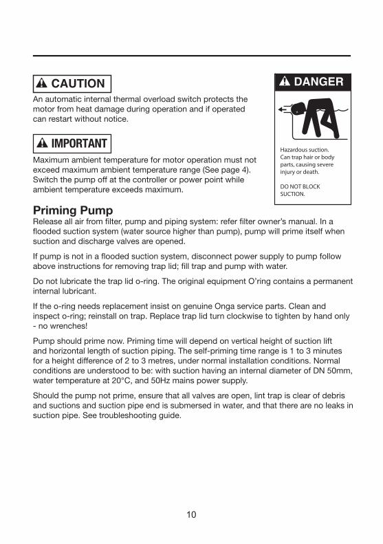
An automatic internal thermal overload switch protects the motor from heat damage during operation and if operated can restart without notice.
Maximum ambient temperature for motor operation must not exceed maximum ambient temperature range (See page 4). Switch the pump off at the controller or power point while ambient temperature exceeds maximum.
Priming PumpRelease all air from fi lter, pump and piping system: refer fi lter owner’s manual. In a fl ooded suction system (water source higher than pump), pump will prime itself when suction and discharge valves are opened.
If pump is not in a fl ooded suction system, disconnect power supply to pump follow above instructions for removing trap lid; fi ll trap and pump with water.
Do not lubricate the trap lid o-ring. The original equipment O’ring contains a permanent internal lubricant.
If the o-ring needs replacement insist on genuine Onga service parts. Clean and inspect o-ring; reinstall on trap. Replace trap lid turn clockwise to tighten by hand only - no wrenches!
Pump should prime now. Priming time will depend on vertical height of suction lift and horizontal length of suction piping. The self-priming time range is 1 to 3 minutes for a height difference of 2 to 3 metres, under normal installation conditions. Normal conditions are understood to be: with suction having an internal diameter of DN 50mm, water temperature at 20°C, and 50Hz mains power supply.
Should the pump not prime, ensure that all valves are open, lint trap is clear of debris and suctions and suction pipe end is submersed in water, and that there are no leaks in suction pipe. See troubleshooting guide.

To avoid dangerous or fatal electrical shock hazard, turn OFF power to motor and remove plug from power outlet before working on pump or motor.
Routine Maintenance requires regular checking of the pump to ensure no water is leaking from joints whilst pump is operating and inspection/cleaning of trap basket. Debris or trash that collects in basket will choke off water fl ow through the pump.
Do not operate pump with trap basket missing or damaged.
Follow instructions below to clean trap:
1. Switch off power to pump, close valves in suction and discharge, and release all pressure from system before proceeding.
2. Remove trap cover (turn clockwise). If necessary, tap handles gently with a rubber mallet or use a board as a lever.
3. Remove strainer basket and clean. Ensure all holes in basket are clear, fl ush basket with water and replace in trap with large opening at pipe connection port (between ribs provided). If basket is replaced backwards, the cover will not fi t on trap body. To clean tranparent cover, use water and neutral soap only. Do not use solvents.
4. Clean and inspect lid o-ring; reinstall on trap.
5. Clean O’ring groove on trap body and replace cover. To help keep cover from sticking, tighten hand tight only.
6. Prime pump (refer priming instructions).
Pump ServicePump should only be serviced by qualifi ed personel. For best results, use onlygenuine Onga service parts. Be sure to prime pump before starting.
Before removing clamp or trap cover:1. SWITCH OFF POWER to pump before proceeding.2. CLOSE SHUT-OFF VALVES in suction and discharge pipes.3. RELEASE ALL PRESSURE from pump and piping system.4. NEVER tighten or loosen covers, valves, nuts or bolts while pump is
operating!
11
Service & Maintenance
12
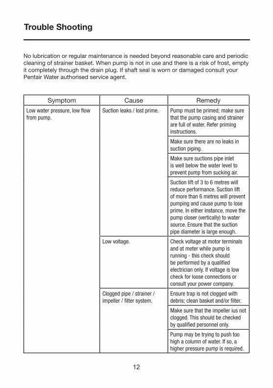
No lubrication or regular maintenance is needed beyond reasonable care and periodic cleaning of strainer basket. When pump is not in use and there is a risk of frost, empty it completely through the drain plug. If shaft seal is worn or damaged consult your Pentair Water authorised service agent.
Symptom Cause Remedy
Low water pressure, low fl ow from pump.
Suction leaks / lost prime. Pump must be primed; make sure that the pump casing and strainer are full of water. Refer priming instructions.
Make sure there are no leaks in suction piping.
Make sure suctions pipe inlet is well below the water level to prevent pump from sucking air.
Suction lift of 3 to 6 metres will reduce performance. Suction lift of more than 6 metres will prevent pumping and cause pump to lose prime. In either instance, move the pump closer (vertically) to water source. Ensure that the suction pipe diameter is large enough.
Low voltage. Check voltage at motor terminals and at meter while pump is running - this check should be performed by a qualifi ed electrician only. If voltage is low check for loose connections or consult your power company.
Clogged pipe / strainer /impeller / fi lter system.
Ensure trap is not clogged with debris; clean basket and/or fi lter.
Make sure that the impeller ius not clogged. This should be checked by qualifi ed personnel only.
Pump may be trying to push too high a column of water. If so, a higher pressure pump is required.
Trouble Shooting

13
Trouble Shooting
Symptom Cause Remedy
No water coming from pump (Pump is working).
Air ingress to system. Prime the pump. Check that there are no air leaks in the suction piping or fi ttings. Ensure the strainer lid is airtight and fi tted securely.
Pump does not work.. Motor termal overload tripped.
Check for required ventilation and cooling. If temperature is above the pump’s maximum ambient, turn off pump until it cools down.
No power at outlet. Use another electricial appliancethat is known to work to checkpower outlet.
Blown fuse / Circuit breaker. Check and call electrician if necessary.
Motor burnt out due to voltage spike or fl ooded by water.
The motor may need replacing.
Pump running too slow. Motor capacitor may be damaged.
Check line voltage; if less that 90% or more that 106% of rated voltage consult a licensed electrician.
Water leaking from between the casing and motor.
Casing bolts are not tightened suffi ciently; worn mechanical seal requires replacing.
Switch off the power to the pump. Tighten the casing bolts or replace the mechanical seal as required.
Should problems persist, contact your nearest Pentair Water Service Agent.
14
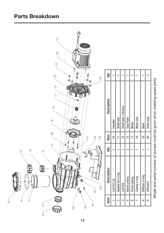
Parts Breakdown
Item
Desc
riptio
nQt
yIte
mDe
scrip
tion
Qty
1 L
int P
ot L
id1
10 I
mpe
ller
1
2 B
aske
t lid
o-r
ing
111
Sha
ft se
al1
3 L
int P
ot1
12 S
haft
seal
/ ce
ram
ic1
4 B
arre
l uni
ons
213
Sea
l Pla
te1
6 P
ump
casi
ng1
17 M
otor
1
7 C
asin
g o-
ring
118
Mot
or p
ad1
8 D
iffus
er o
-rin
g1
19 B
ase
1
9 D
iffus
er2
120
Dra
in p
lug
2
Mod
el a
nd s
eria
l num
ber
of p
ump
s m
ust
be
give
n w
hen
ord
erin
g sp
are
par
ts

15
Notes

16
Notes
17
Pentair Water Product Warranty
Pentair Water warrants that, when this product is used for the purpose it was designed, is correctly housed and vented against weather, vermin, dust etc., that it will be free of material and manufacturing defects at the time of the original purchase.This warranty is limited to the cost of the product and does not cover third party costs including the costs of electricians, plumbers, etc. unless authorised by Pentair Water.
TERMS AND CONDITIONS APPLICABLE INTERNATIONALLYHow long the warranty is effective Internationally
1) This Pentair Water product is warranted for 12 months for all parts from the date of the first consumer purchase. Should any parts fail as a result of such defects within the specified period, the part will be replaced free of charge. (This does not include travel charges, removal and reinstallation charges.)
TERMS AND CONDITIONS APPLICABLE IN AUSTRALIA ANDNEW ZEALAND
1) YOU SHOULD CAREFULLY READ THE INSTRUCTIONS SUPPLIED PRIOR TO USING THIS PENTAIR WATER PRODUCT.
This product is to be installed and operated in accordance with the instructions provided. This warranty will not apply if it is used in a manner other than in accordance with the instructions.
What the warranty covers:
Pentair Water warrants its products to be free of defects in material and workmanship during the warranty period. If a product proves to be defective in material or workmanship during the warranty period, then Pentair Water will, at its sole option repair or replace the product with a like product. Replacement product or parts may include re-manufactured or refurbished parts or components.
How long the warranty is effective:
1) This Pentair Water product is warranted for 36 months for all parts from the date of the first consumer purchase.
2) Authorised workshop labour will be free of charge for the first 12 month period from date of the first consumer purchase when unit is found to have failed due to defective workmanship or material supplied by
Pentair Water Australia. Infield service by an authorised Pentair Water Service Agent will incur a travel, removal & reinstallation fee
payable by customer.
3) Where this Pentair Water product is sold for commercial application as defined in the relevant Trade Practices and Consumer Protection legislation the warranty shall be for a period of six months from the date of purchase by the end user.
Who the warranty protects:
This warranty is valid only for the consumer purchaser.
What the warranty does not cover:
1) Damage, deterioration or malfunction resulting from: a) accident, misuse, negligence, fire, water, lightning, or other acts of nature, unauthorised product
modification or failure to follow instructions supplied with the product; b) repair or attempted repair by anyone not authorised by Pentair Water; c) any damage to the product due to shipment; d) removal or installation of the product; e) causes external to the product such as electric power fluctuations or failure; f) use of supplies or parts not meeting Pentair Water specifications; g) normal wear and tear;
18
h) water ingression or exposure to abnormal corrosive conditions or “run dry” conditions; i) any other cause which does not relate to a product defect.2) Damage caused to the product as a consequence of use of another manufacturer’s product used in conjunction
with Pentair Water and affiliate companies.3) Ingress of insects into the unit causing electrical malfunction is not warranted, care should be taken to avoid
this occurrence.
Spare Parts:
Spare parts are usually stocked for a reasonable period of time following last production.
Pentair Water does not warrant that spare parts will be made available for the whole of the reasonable period and reserves its right to cease supplying spare parts or providing facilities for repair of spare parts in circumstances which are beyond its control including the requirement to remove spare parts from sale as a consequence of changes in the law or otherwise as it deems fit.
How to get service:
In Australia please contact 1800 664 266 In New Zealand please contact 0800 664 269Claims under this warranty must give evidence of date of purchase, model and serial number of the product and the claimants name, address and telephone number.
1) To obtain warranted service, you will be required to provide to either Pentair Water state office or recommended service agent:-
a) the product; b) confirmation in writing specifying the nature of your claim; c) proof providing date of original purchase; d) full contact details including name and address; e) the serial number of the product if any.2) The product is to be forwarded by the customer freight paid to an Authorised Pentair Water service agent. 3) Warranty service work will be denied or suspended, on equipment not readily accessible to service personnel,
that is products that are behind barriers, tiled or bricked in, installed in roofs or second story external walls including inaccessible power points.
4) Any service of any product which is found to be faulty due to abuse, fair wear & tear, misuse or improper installation will be charged to the owner at the service agents current servicing hourly rate.
Limitation of implied warranties:
THERE ARE NO WARRANTIES, EXPRESSED OR IMPLIED, WHICH EXTEND BEYOND THE DESCRIPTION CONTAINED HEREIN INCLUDING THE IMPLIED WARRANTY OF MERCHANTABILITY AND FITNESS FOR A PARTICULAR PURPOSE.
Exclusion of damages:PENTAIR WATER’S LIABILITY IS LIMITED TO THE COST OF REPAIR OR REPLACEMENT OF THE PRODUCT. ONGA SHALL NOT BE LIABLE FOR:
1) DAMAGE TO OTHER PROPERTY CAUSED BY ANY DEFECTS IN THE PRODUCT, DAMAGES BASED UPON INCONVENIENCE, LOSS OF USE OF THE PRODUCT, LOSS OF TIME, LOSS OF PROFITS, LOSS OF BUSINESS OPPORTUNITY, LOSS OF GOODWILL, INTERFERENCE OF BUSINESS RELATIONSHIPS, OR OTHER COMMERCIAL LOSS, EVEN IF ADVISED OF THE POSSIBILITY OF SUCH DAMAGE.
2) ANY OTHER DAMAGES, WHETHER INCIDENTAL, CONSEQUENTIAL OR OTHERWISE.3) ANY CLAIM AGAINST THE CUSTOMER BY ANY OTHER PARTY.
Effective law:
This warranty gives you specific legal rights, and you may also have other rights which vary from state to state. Nothing in this warranty limits or restricts, or is intended to derogate from, any right or remedy which the purchaser or ultimate user of the product may have pursuant to Australian state and/or Australian federal consumer protection legislation, New Zealand Sale of Goods Act, Consumer Guarantees Act, Fair Trading Act or any other relevant and applicable New Zealand legislation or authority and where necessary shall so be read and construed.
Pentair Water Product Warranty (Continued)
L300
115
1010
IMPORTANTPlease attach your sales invoice/docket here as proof of purchase should warranty service be required.
Please do not return Warranty - Retain for your records.
Purchased From ...................................................................................................................
Purchase Date..................................... Serial No.............................. Model No........................
Disclaimer: Every endeavour has been made to publish the correct details in this data sheet. No responsibility will be taken for errors, omissions or changes in product specifi cations.
Pentair Water reserves the right to change specifi cations
Pacifi c Head Offi ceAustralia Pentair Water Australia Pty Ltd Notting Hill Victoria, Australia Tel: 1300 137 344 Int. Tel: +613 9574 4000 Fax: 1800 006 688 Int. Fax: +613 9562 7237 Email: [email protected] www.pentairwater.com.au
Pentair Water New Zealand Ltd Penrose Auckland New Zealand Tel: +64 9579 6254 Fax: +64 9579 6497
North, Central 1620 Hawkins Avenue Sanford, North Carolina, 27330 & Latin America Phone: 1-800-831-7133 www.pentaircommercial.com
Europe, Toekomstlaan 30, 2200 Herentals, Belgium Middle East Phone: +32-14-25-99-11 Fax: +32-14-25-99-73 and Africa Email: [email protected]
Asia China www.pentairwater.com
India www.pentairwater.com