Embed Size (px)
Citation preview
LIQUID RING PUMPMV and MVP Design
INSTALLATION, OPERATION
AND
MAINTENANCE MANUAL
Graham Corporation20 Florence Avenue
Batavia, New York 14020(716) 343-2216, Fax (716) 343-1097
e-mail: [email protected]
IOM-MV-799
Vacuum and Heat Transfer

2
Table of Contents
Page No.Section 1 - General Information................................................................................................ 4
1.1 Introduction........................................................................................................................ 41.2 General Description and Principle of Operation.................................................................... 51.3 Description of Pump Model Codes...................................................................................... 6
Section 2 - Installation Instructions ........................................................................................... 72.1 Handling ............................................................................................................................. 72.2 Preservation........................................................................................................................ 72.3 Mounting ............................................................................................................................ 72.4 Installation........................................................................................................................... 72.5 Coupling Alignment ............................................................................................................. 82.6 Service Liquid Piping Arrangements..................................................................................... 9
A) Typical Installation of Once Through with No Recovery.................................................. 10B) Typical Installation of Closed Loop with Total Recovery................................................. 11C) Draining Before Start-Up ............................................................................................... 12
2.7 Shaft Seal Coolant ............................................................................................................ 122.8 Piping Requirements.......................................................................................................... 12
A) Suction and Discharge Piping.......................................................................................... 12B) Service Liquid Piping...................................................................................................... 12
2.9 Electrical Requirements ..................................................................................................... 13
Section 3 - Operating Instructions ........................................................................................... 143.1 Start-up Procedures.......................................................................................................... 143.2 Service Liquid Requirements ............................................................................................. 14
A) Flow Rates .................................................................................................................... 14B) Flow Control.................................................................................................................. 15C) Hard Water ................................................................................................................... 15
3.3 Cavitation......................................................................................................................... 153.4 Shut-Down Procedures..................................................................................................... 15
Section 4-Accessory Items ...................................................................................................... 164.1 Accessories ...................................................................................................................... 16
Section 5-Maintenance ............................................................................................................ 185.1 Performance ..................................................................................................................... 185.2 MV and MVP Pump Estimated Weights (lbs.)................................................................... 185.3 Shaft Bearings................................................................................................................... 185.4 Mechanical Seals .............................................................................................................. 185.5 Storage ............................................................................................................................. 195.6 Removal from storage ....................................................................................................... 195.7 Troubleshooting Chart....................................................................................................... 20

Graham Corporation
3
Table of Contents
Page No.Section 6-Disassembly And Reassembly Procedures............................................................ 21
6.1 General............................................................................................................................. 216.2 Impeller End Clearances.................................................................................................... 21
A) Gasketed Pumps............................................................................................................ 22B) Non-Gasketed Pumps.................................................................................................... 22
6.3 Tie Rod Torque Values..................................................................................................... 226.4 Bearing Data..................................................................................................................... 23
Section 7-Warranty .................................................................................................................. 24
Appendices
Appendix A - MSDS Form - Preservative .......................................................................... 25Appendix B - Return Material Authorization (RMA) Form .............................................. 29

Graham Corporation
4
Section 1 - General Information
1.1 Introduction
This manual will provide assistance in the set-up, operation, and maintenance of your GrahamLiquid Ring Pump. Please read this manual completely prior to operating your Liquid Ring Pump. Ifyou need to contact the Pump Service department for assistance, please have available the pumpserial number and model number. The Pump Service department may be reached by contactingGraham Corporation in Batavia, NY by phone (716) 343-2216, Fax (716) 343-1097, or e-mailat [email protected].
Graham has an extensive stock of spare parts and replacement pumps. Stocked parts and pumpscan be shipped from our warehouse in Batavia, NY, by a carrier of your choice.
For your convenience, use our toll free number ( 1-800-828-8150 ) only when ordering spareparts and replacement pumps. Please have the model number, serial number and part number ofthe items required when placing an order. Normal business hours are 8:00 a.m. to 5:00 p.m.(E.S.T.), Monday through Friday.
Factory rebuilding service is available for pumps returned to Batavia. When a pump is returned tothe factory for repairs, please drain and flush the pump and include a Material Safety Data Sheet(MSDS) for the process in which the pump was used. A Return Material Authorization (RMA)Number, issued by Graham, is required before returning a pump. A sample form is included at theback of this manual to show what type of information is required to obtain an RMA Number.Field Service Technicians are also available for travel to the jobsite for troubleshooting and repairor rebuilding of pumps.
This document and the information contained herein are the property of Graham Corporation andmust not be copied, in whole or in part, nor used for manufacture or otherwise disclosed withoutthe prior written consent of the company. Information contained herein may, from time to time, berevised and/or updated. Copyright Graham Corporation 1999

Graham Corporation
5
1.2 General Description and Principle of Operation
Graham Vacuum Pumps and Compressors are of the liquid ring type. The MV and MVP pumpdesigns are single stage and available in a wide range of sizes and materials. These are listed in theGraham Sales Bulletins.
For the MV design, the pump is mounted directly to the motor with the motor being the completesupport. It is commonly called a close-coupled arrangement. The MVP design is called apedestal type and permits the pump and motor to be separately supported and mounted on abaseplate.
The major component of the liquid ring pump is a multi-bladed rotating assembly positionedeccentrically in a cylindrical casing. (See Figure 1) This assembly is driven by an external source,normally an electric motor. Service liquid (usually water) is introduced into the pump. As theimpeller rotates, centrifugal force creates a liquid ring which is concentric to the casing. At the inlet,the area between the impeller blades (buckets) increase in size, drawing gas in. As the impellercontinues to rotate toward the discharge, the impeller bucket area decreases in size, compressingthe gas. This gas, along with the liquid from the pump, is discharged through the outlet nozzle. Theservice liquid is separated from the gas and cooled for reuse in the pump or sent to a drain. Inaddition to being the compressing medium, the liquid ring performs two other important functions:
1) It absorbs the heat generated by compression, friction, and condensation of theincoming vapor.
2) It absorbs and washes out any process contaminants entrained in the gas.
Figure 1
DischargePort
Gas andLiquid Outlet
Impeller
Suction Port
Liquid Ring
Casing
Gas Inlet
Gas

Graham Corporation
6
A continuous supply of service liquid is necessary to limit the temperature rise in the pump causedby the heat of compression, friction, and condensation. Any excessive rise in temperature will havea detrimental effect on performance, reducing the capacity and degree of vacuum attainable.Installation schematics for the supply of the service liquid and for the separation of the gas andliquid discharged from the pump are shown in Section 2.
Service liquid quantities are a function of the particular model and the intended application. Checkthe data sheet for your specific pump model or see Table 1 of Section 3 which lists typical serviceliquid requirements.
The normal operating range of the MV or MVP design when using water at 59º F(15 ºC) for the service liquid is from atmosphere down to 30 mmHgA.
The standard materials of construction are suitable for handling air and other non-corrosive gases,while using water as the service liquid. Other materials can be supplied for special applications.
1.3 Description of Pump Model Codes
Each pump is designated by a model code which describes the materials of construction, size, typeof shaft seals, and any special features. An example of a typical pump is shown below. ContactGraham for a complete listing of the codes used to describe the pump.
Number of Stages
Frame Size
Pump Design
Impeller Size
Shaft Seal Code
Motor Voltage
MV 32.1.20 / 10 / 75 / I / E2
Connectionand ShaftEnd Type
PumpMaterialCode
Close-Coupled = MVPedestal = MVP
Graham Corporation
7
Section 2 - Installation Instructions
2.1 Handling
Carefully unpack the pump. MV pumps may be lifted with a sling placed under the pump- motorassembly. Since the MVP pump is normally baseplate mounted, lift by the baseplate only. Do notattach slings nor hooks to the motor or the pump as this can cause misalignment. Do not attemptto run the pump until the installation work is complete.
CAUTION : DO NOT RUN THE PUMP WITHOUT SERVICE LIQUID AND SHAFTSEAL COOLANT.
2.2 Preservation
Cast iron pumps are protected internally with a preservative solution applied at the factory beforeshipping. The solution should be flushed from the pump prior to use. An MSDS form is includedin the back of this manual.
The preservative solution is petroleum based and must be disposed of in accordance withall Local, State, and Federal regulations.
2.3 Mounting
Before operation, the pump package should be carefully set, leveled, and securely bolted in place.It is recommended that shims and grout be used as necessary under all structural members of thebase.
Baseplates supplied with a pump and drive motor mounted at the factory should be leveled,shimmed as required, and firmly anchored.
2.4 Installation
All piping to the pump should be adequately supported to eliminate any stress at the pumpconnections. All piping joints should be tested for leaks prior to start-up. A temporary start-upstrainer in the process inlet piping may be used to keep large contaminates from entering the pumpat start-up.
The location of the installation or the storage of the pump should be in an area that willnot subject the pump to freezing.
Verify the pump’s rotation direction by checking the arrow on the shaft end casing. Refer toparagraph 2.9 concerning the electrical requirements.
Graham Corporation
8
2.5 Coupling Alignment - MVP design only
CAUTION : TO PREVENT PERSONAL INJURY, DO NOT OPERATE THE PUMPWITHOUT PROPERLY GUARDING THE DRIVE COUPLING(S).
Pumps supplied from the factory packaged with a motor have had the shafts aligned prior toshipment. This ensures that alignment can be done in the field. It is required that the shaftalignment be rechecked after mounting on a level foundation and prior to start-up.
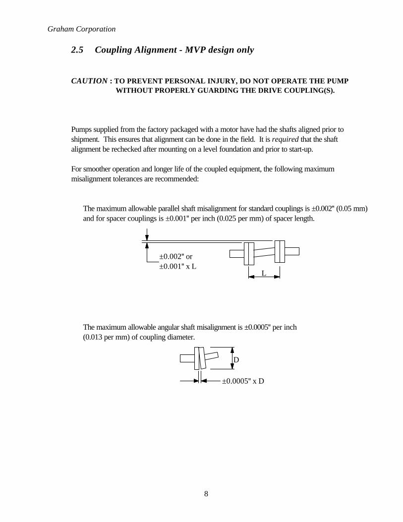
For smoother operation and longer life of the coupled equipment, the following maximummisalignment tolerances are recommended:
The maximum allowable parallel shaft misalignment for standard couplings is ±0.002" (0.05 mm)and for spacer couplings is ±0.001" per inch (0.025 per mm) of spacer length.
The maximum allowable angular shaft misalignment is ±0.0005" per inch(0.013 per mm) of coupling diameter.
±0.002" or±0.001" x L
L
D
±0.0005" x D

Graham Corporation
9
2.6 Service Liquid Piping Arrangements
The operating principle of a liquid ring pump depends on a continuous supply of clean service liquid,which is normally water. The liquid enters the pump through a connection on the casing and isdischarged from the pump along with the gas. There are two basic piping arrangements that can beused for liquid ring pump applications. A once-through method with no recovery of the serviceliquid and a total recirculation method which re-uses the service liquid.Both of these arrangements have four basic elements:
1) A supply of service liquid.2) A means to control flow of service liquid.3) A means of stopping the flow of service liquid when the pump is off.4) A means of separating the gas / liquid exhaust mixture.
It is recommended to use a strainer to ensure that foreign matter does not enter the pump with theservice liquid supply or make-up source. See Diagrams 1 and 2 for the proper piping arrangementscheme.
CAUTION: COMPLETE ALL PIPING INSTALLATION AND MAKE SURE ASUPPLY OF SERVICE LIQUID AND SHAFT SEAL COOLANT AREAVAILABLE BEFORE STARTING THE PUMP.

Graham Corporation
10
A) Typical Installation of Once Through with No Recovery
The service liquid is piped directly from a supply source to the pump. The liquid is separated fromthe gas in the separator and discharged to a drain. No recirculation nor recovery takes place. Thisis the most basic arrangement and can be used when service liquid conservation or contaminationis not a concern. A solenoid operated valve provides for flow of the liquid simultaneously with thepump/motor operation. When the motor stops, the valve closes to prevent the pump casing fromfilling with fluid. The by-pass valve is used to pre-fill the pump at initial start-up only. It also can beused should the solenoid fail. When a manual valve is used, it must be opened immediately afterstarting the motor and closed immediately before turning the motor off.
A–Inlet Check Valve G–Shut-off ValveB–Vacuum Gauge H–Regulating ValveC–Vacuum Relief Valve J–Solenoid ValveD–Separator K–Compound GaugeE–By-Pass Valve L–Liquid Ring PumpF–Strainer M–Trap (required if discharge pressure is
above atmospheric pressure)
Once Through with No RecoveryDiagram 1
ProcessInlet
ServiceLiquid Inlet
GasOutlet
LiquidDrain
S
A D
F G H
E
J K
CB
ML

Graham Corporation
11
B) Typical Installation of Closed Loop with Total Recovery
This arrangement provides for the total recirculation of the service liquid. A heat exchanger is addedto the system to remove the heat of compression, friction, and condensation from the service liquidbefore it is re-introduced to the pump.
The service liquid level in the separator of a total recovery system should be at or slightly below thecenterline of the pump shaft. A provision should be made for a high level overflow. This willprevent starting the pump while it is full of liquid, which will damage the pump or overload themotor.
A–Inlet Check Valve H–Compound GaugeB–Pressure Gauge J–Liquid Ring PumpC–Vacuum Relief Valve K–Recirculation Pump (recommended)D–Level Gauge L–Trap or Loop Seal (required if dischargeE–Separator pressure is above atmospheric pressure)F–Service Liquid Cooler M–Drain ValveG–Shut-off or Throttling Valve N–Make-Up Valve
Closed Loop–Total RecoveryDiagram 2
M N
LG
ProcessInlet
CoolingLiquid Inlet
Cooling LiquidOutlet
GasOutlet
Overflow
Make-upDrain
A E
F
K
B D
H
C
G
J
L

Graham Corporation
12
C) Draining Before Start-Up
CAUTION : DO NOT START THE PUMP WITH THE CASING FULL OF LIQUID.
A Liquid Ring Pump should not be started with the casing full of liquid. Damage to the impeller orthe shaft will result. The normal liquid level should be no higher than the shaft centerline. The pumpmay be started with a low liquid level as long as a supply of service liquid is available immediatelyafter start-up.
2.7 Shaft Seal Coolant
On the MV and MVP pumps, the service liquid connection is positioned on the pump casing toflush the mechanical seal along with introducing service liquid to the pump. No separate source ofshaft seal coolant is required for this design.
2.8 Piping Requirements
A) Suction and Discharge Piping
The suction and discharge connections on the pump are arranged vertically and are marked witharrows on the pump casing. The suction and discharge piping should be the same nominal size as thepump connections. The elevation of the discharge separator above the discharge connection shouldbe limited to an elbow turning horizontally.
If necessary, a discharge leg can be used with a maximum of 12 inches (305 mm) above the pumpdischarge connection. Too high an elevation in this line will cause excessive backpressure on thepump, overload the motor, and reduce the pump capacity.
Remove the protective coverings from the pump openings just before attaching the piping. Checkthat all foreign matter such as weld slag, nuts, bolts, rags, and dirt has been cleaned out of the pipingbefore connecting to the pump. The piping must fit easily and without strain on the pumpconnections and the mating flange bolt holes must be in alignment. The mating flange gaskets mustnot protrude into the bore of the piping or pump connections. All piping must be supportedindependently on each side of the pump without transmitting any strain to the pump casing. Atemporary suction strainer fitted at the suction inlet is recommended during the first 100 hours ofoperation.
B) Service Liquid Piping
In a once-through arrangement, the nominal pipe size should be the same size as the service liquidconnection. In a total recirculation package with no recirculation pump, use one nominal pipe sizelarger than the service liquid connection of the pump. Also, use the least number of fittings tominimize the pressure drop. When a recirculation pump is used, the piping should be the same sizeas the service liquid connection.

Graham Corporation
13
2.9 Electrical Requirements
All electrical wiring and installation must comply with local safety codes.After the electrical work is complete, the motor should be jogged to check for proper rotation.
First, turn the pump by hand to see that it rotates freely. The direction of rotation is marked on thepump. With the power off, the motor fan can be used to rotate the MV design.
Second, jog the motor momentarily to check the rotation. It is recommended to use a non-reversing motor controller to prevent the pump from turning in the wrong direction.

Graham Corporation
14
Section 3 - Operating Instructions
3.1 Start-up Procedures
Read all instructions before proceeding.
1) Turn the shaft manually to ensure it rotates freely. If the pump is binding or seized, refer to thetroubleshooting chart in Section 5. With the power off, the motor fan can be used to rotate theMV design.
2) Fill the pump with service fluid to the shaft centerline, but do not overfill
CAUTION : DO NOT RUN THE PUMP WITHOUT SERVICE LIQUID AND SHAFT SEAL COOLANT.
3) The normal service liquid level should be no higher than the shaft centerline. The pump may bestarted with a low service liquid level as long as a supply is available immediately after start-up.
4) Open any valves in the suction and discharge lines.5) Confirm the pump rotation with the arrow on the casing by jogging the motor.6) Start the motor, ensure service liquid supply, and set regulating valve, when used, for optimum
pump performance. Open and adjust the shaft seal cooling liquid valve, when used.
3.2 Service Liquid Requirements
A) Flow Rates
Service liquid flow rates depend on the type of piping arrangement used, the size and operatingspeed of the pump, and the allowable temperature rise through the pump. Nominal flow rates forstandard pumps at normal conditions are given in Table 1.
Service liquid flow rates and the temperature rise are important because of their effect on pumpperformance. Too little flow will result in loss of capacity. Too much flow will result in excessivehorsepower requirements.
Service Liquid Flow Rates*MV or MVP Pumps
Pump Model USGPM
MV12.1.20 1.5MV32.1.20 1.7MV32.1.25 2.2MV32.1.45 2.5MV32.1.65 3MV40.1.50 4.4MV40.1.60 5.5
MV41.1.100 8.8* Applies to MV or MVP design. For unitsin m3/hr, multiply USGPM by 0.227
Table 1
Graham Corporation
15
B) Flow Control
If a flow device is not used to measure the service liquid quantity to the pump, a regulating valveand compound gauge in the service liquid line can be used to approximate the flowrate. For pumpoperating pressures between atmospheric and 400 mmHgA, the reading on the compound gaugeshould be in the range of 2" HgV to 5 psig (709 mmHgA to 0.35 barg). For operating pressuresbelow 400 mmHgA, the compound gauge reading should be in the range of 15" HgV to 2 psig(379 mmHgA to 0.14 barg). This method is only an approximation of the service liquid quantity.The actual operating conditions will dictate the amount of service liquid required and also thecompound gauge reading.
C) Hard Water
If hard water is used as the service liquid, scale deposits caused by the precipitation of minerals willoccur. This will vary with the temperature of the water. Scale deposits on the internal surfaces ofthe pump will cause an increase of the operating horsepower, wear on moving parts, and maycause the pump to seize. If the hardness of the water is excessive, consider using a water softeningtreatment.
3.3 Cavitation
Cavitation is identified by a characteristic metallic or grinding noise inside the pump. It is causedwhen the pump suction pressure is too close to the vapor pressure of the service liquid. If theservice liquid temperature inside the pump rises such that its vapor pressure closely approaches thesuction pressure of the pump, cavitation will occur.
When cavitation takes place, vapor bubbles form and collapse within the liquid ring. This willdamage the surfaces of the impeller, side plates, and casing. Cavitation causes damage by tearingaway metal particles. The damage may be more severe in a corrosive situation.
Cavitation may be prevented by bleeding air into the pump to raise the suction pressure. Vacuumrelief valves can be fitted in the suction piping for this purpose.
If the problem is not caused by a low flow of non-condensable gases, the service liquidtemperature should be checked. Ultimately, the vacuum at which the pump can be operated isgoverned by the vapor pressure of the service liquid inside the pump.
3.4 Shut-Down Procedures
1. Shut off the service liquid and shaft seal coolant supply, and immediately stop the motor.2. If necessary, close all suction and discharge valves.3. If necessary, drain the pump to protect it from freezing by removing all drain plugs.4. Disconnect power from the motor if maintenance is to be performed.

Graham Corporation
16
Section 4 - Accessory Items
4.1 Accessories
There are many accessory items associated with Liquid Ring Vacuum Pumps. They can besupplied by Graham and shipped from the factory or can be supplied by others and installed in thefield. The particular requirements, mode of operation, and type of control scheme desired dictatethe necessity of various items. The following is a list of common accessories.
Inlet Check Valve Used to prevent a back flow of gas into the process when the pump isstopped. Check valves are normally installed in a horizontal line. Anelbow can be provided to adapt the vertical pump inlet to accept ahorizontal check valve.
Vacuum Relief Valve Used to protect the pump from cavitation and control the pump suctionpressure. When the pump capacity exceeds the system’s flowrequirements at a pre-determined level, the valve will open and bleed inatmospheric air or process gas.
Flexible Connector Used to compensate for minor misalignment or expansion between thepump connections and the process piping.
Vacuum Gauge Used to indicate vacuum at the pump inlet. Normally mounted directlyahead of the pump suction.
Shut-off Valve Used to manually stop the flow of service liquid to the pump.
Strainer Used to filter out solid particles that will damage the pump.
Flow Regulator Used to control the service liquid flow rate to the pump.A manual valve, a fixed orifice, or a flexible element orifice may be useddepending on the application.
Compound Gauge Used to indicate pressure in the service liquid piping.
Discharge Separator Used to separate the service liquid from the discharged gas as it comesout of the pump. The liquid can be piped to a drain or recovered forreuse.
Solenoid Valve Used to automatically stop or start the flow of service liquid to the pump.Normally interlocked to the pump motor.
By-pass Valve Used to initially fill the pump with service liquid or for bypass in case thesolenoid coil fails.
Graham Corporation
17
Recirculation Pump Used to circulate the service liquid recovered from the dischargeseparator in some total recovery systems.
Heat Exchanger Used to remove heat from the recirculated service liquid.
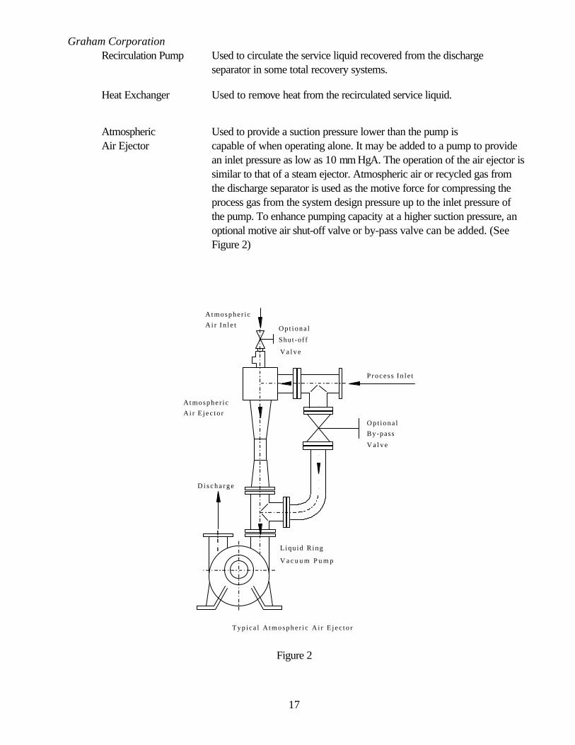
Atmospheric Used to provide a suction pressure lower than the pump isAir Ejector capable of when operating alone. It may be added to a pump to provide
an inlet pressure as low as 10 mm HgA. The operation of the air ejector issimilar to that of a steam ejector. Atmospheric air or recycled gas fromthe discharge separator is used as the motive force for compressing theprocess gas from the system design pressure up to the inlet pressure ofthe pump. To enhance pumping capacity at a higher suction pressure, anoptional motive air shut-off valve or by-pass valve can be added. (SeeFigure 2)
P r o c e s s I n l e t
Op t iona l
By-pass
V a l v e
Liqu id R ing
V a c u u m P u m p
D i s c h a r g e
Atmosphe r i c
A i r E j e c t o r
T y p i c a l A t m o s p h e r i c A i r E j e c t o r
Op t iona l
Shut -of f
V a l v e
Atmosphe r i c
A i r I n l e t
Figure 2

Graham Corporation
18
Section 5 - Maintenance
5.1 Performance
Optimum performance and long service life are dependent upon good maintenance procedures andperiodic inspections. When preparing to dismantle a pump, make provisions for the safe handling ofheavy parts.
5.2 MV and MVP Pump Estimated Weights (lbs.)*
MV Model Dry MVP Model Dry
MV12.1.20 24 MVP12.1.20 18MV32.1.20 51 MVP32.1.20 35MV32.1.25 62 MVP32.1.25 37MV32.1.45 70 MVP32.1.45 44MV32.1.65 86 MVP32.1.65 53MV40.1.50 132 MVP40.1.50 95MV40.1.60 158 MVP40.1.60 100MV41.1.100 354 MVP41.1.100 N/A
* For units in kg, multiply lbs. by 0.454
Table 2
5.3 Shaft Bearings
The MV and MVP pumps use sealed-for-life bearings that are not regreaseable.
The standard bearings are rated for an L10h life of 80,000 hours. The temperature of the bearingsshould not exceed 140ºF (60ºC). Overheating may be due to misalignment of the shafts or a badbearing.
5.4 Mechanical Seals
The MV and MVP pumps are fitted with a single acting mechanical shaft seal. It should bereplaced when worn, scratched, or cracked, or when the rotating segment no longer grips theshaft.
When replacing the mechanical seal, clean the shaft thoroughly. The seal faces must be protectedduring installation from particles which may scratch the surfaces.
CAUTION : DO NOT RUN THE PUMP WITHOUT SERVICE LIQUID ANDSHAFT SEAL COOLANT.

Graham Corporation
19
5.5 Storage
If a pump is to be out of service, it should be protected internally from rusting by using a rustinhibitor. The pump should be drained completely by removing all lower plugs. Install the plugs andfill with Oakite HPO (or equal) preservative solution. Rotate the pump manually to circulate thesolution. With the power off, the motor fan can be used to rotate the MV design. Drain the pumpto the shaft centerline. This procedure may be disregarded for pumps made of stainless steel orother corrosion resistant materials.
Seal any openings to prevent foreign material from entering the pump.
The pump shaft should be rotated each week to distribute the preservative and to prevent flat spotson the bearings. Document the time, date, and by whom this procedure was performed. With thepower off, the motor fan can be used to rotate the MV design
The pump should be checked to see that the preservative is maintained. This will protect the pumpfor up to twelve months.
Pumps stored at low temperatures may need to be protected from freezing either by drainingcompletely or by using an anti-freeze solution.
5.6 Removal from storage
The pump should be drained and flushed if necessary to remove the preservative solution. Refer toparagraph 3.1 of this manual for the recommended start-up procedure.
CAUTION : THE OAKITE HPO PRESERVATIVE SOLUTION ISPETROLEUM BASED AND MUST BE DISPOSED OF INACCORDANCE WITH ALL LOCAL, STATE, ANDFEDERAL REGULATIONS.
An MSDS form is included in the back of this manual.

Graham Corporation
20
5.7 Troubleshooting Chart
Problem Cause SolutionReducedCapacity
• Speed too low• Leak in suction line• Service liquid temperature too high• Insufficient or excess service liquid• Excessive back pressure
• Check power supply and transmission• Repair• Check coolant flow & heat exchanger• Provide correct flow rate• Eliminate cause of back pressure
ExcessiveNoise
• Excessive or insufficient service liquid• Shaft misalignment• Defective bearing• Cavitation• Back pressure
• Adjust flow rate • Realign shafts• Replace bearing• Adjust vacuum relief valve• Eliminate cause of back pressure
High PowerConsumption
• Excessive service liquid• Shaft misalignment• Excessive back pressure• Defective bearing• Improperly mounted pump • High temperature process load
• Reduce flow rate• Realign shafts• Eliminate cause of back pressure• Replace bearing• Make sure surface is level and all feet
touch the surface, shim if necessary.• Check conditions upstream of pump
Overheating • Service liquid temperature too high• Insufficient service liquid• Shaft misalignment• Defective bearing
• Check coolant flow & heat exchanger• Provide correct flow rate• Realign shafts• Replace bearing
Vibration • Shaft misaligned• Pump or baseplate not properly
anchored• Defective bearing• Improperly mounted pump • Cavitation• Back pressure• Excessive service liquid
• Realign shafts• Anchor • Replace bearing• Make sure surface is level and all feet
touch the surface, shim if necessary.• Adjust vacuum relief valve• Eliminate cause of back pressure• Provide correct flow rate
AbnormalBearing Wearor Failure
• Shaft misalignment• Piping load on pump connections• Mechanical seal leakage
• Realign shafts• Support connecting pipe work• Replace seal
Shaft Will NotTurn orPartially Seizes
• Scale build-up• Foreign object in pump• Piping load on pump connections• Improperly mounted pump • Soft Foot
• Descale pump• Remove foreign object• Support connecting pipe work• Make sure surface is level and all feet
touch the surface, shim if necessary.• Correct pump / motor mounting
Table 3
Graham Corporation
21
Section 6 - Disassembly And Reassembly Procedures
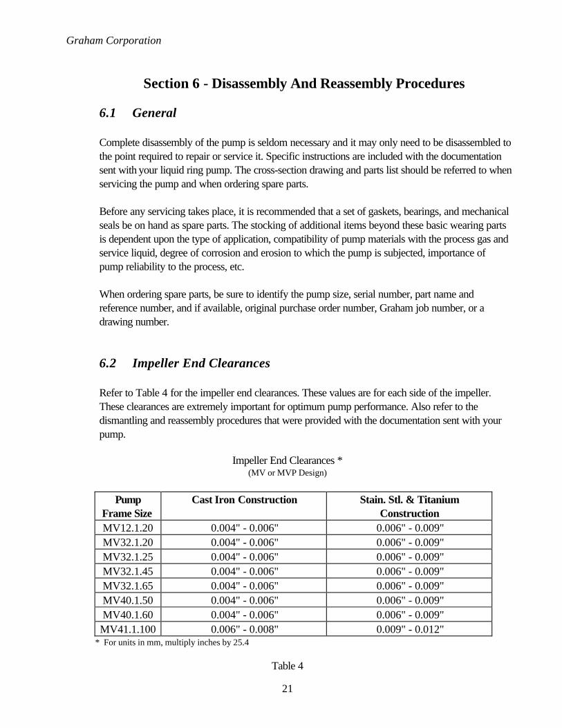
6.1 General
Complete disassembly of the pump is seldom necessary and it may only need to be disassembled tothe point required to repair or service it. Specific instructions are included with the documentationsent with your liquid ring pump. The cross-section drawing and parts list should be referred to whenservicing the pump and when ordering spare parts.
Before any servicing takes place, it is recommended that a set of gaskets, bearings, and mechanicalseals be on hand as spare parts. The stocking of additional items beyond these basic wearing partsis dependent upon the type of application, compatibility of pump materials with the process gas andservice liquid, degree of corrosion and erosion to which the pump is subjected, importance ofpump reliability to the process, etc.
When ordering spare parts, be sure to identify the pump size, serial number, part name andreference number, and if available, original purchase order number, Graham job number, or adrawing number.
6.2 Impeller End Clearances
Refer to Table 4 for the impeller end clearances. These values are for each side of the impeller.These clearances are extremely important for optimum pump performance. Also refer to thedismantling and reassembly procedures that were provided with the documentation sent with yourpump.
Impeller End Clearances *(MV or MVP Design)
PumpFrame Size
Cast Iron Construction Stain. Stl. & TitaniumConstruction
MV12.1.20 0.004" - 0.006" 0.006" - 0.009"MV32.1.20 0.004" - 0.006" 0.006" - 0.009"MV32.1.25 0.004" - 0.006" 0.006" - 0.009"MV32.1.45 0.004" - 0.006" 0.006" - 0.009"MV32.1.65 0.004" - 0.006" 0.006" - 0.009"MV40.1.50 0.004" - 0.006" 0.006" - 0.009"MV40.1.60 0.004" - 0.006" 0.006" - 0.009"MV41.1.100 0.006" - 0.008" 0.009" - 0.012"
* For units in mm, multiply inches by 25.4
Table 4

Graham Corporation
22
A) Gasketed Pumps
The gaskets between the impeller casing and the sideplate determine the impeller end clearances.Check and record the thickness and quantity of these gaskets at each joint when dismantling. Thegaskets may be held in place with grease during re-assembly. The gasket thicknesses used on316SS and high alloy pumps are 0.015" to 0.018" (0.38 to 0.46 mm). Refer to Table 4 for thecorrect impeller end clearances.
Do not use joint sealing compound to replace a gasket as the clearances in the pump willbe affected.
B) Non-Gasketed Pumps
Some of the MV and MVP pumps do not require gaskets, but use a joint sealing compoundbetween the impeller casing and the sideplate. They are machined to accommodate the sameimpeller end clearances as a gasketed pump. Refer to Table 4 for the correct impeller endclearances.
6.3 Tie Rod Torque Values
Table 5 includes torque values for re-assembling the pumps.
MV or MVP Design
Pump Frame Size Tie Rod Torque *MV12.1.20 30 ft.-lbf
MV32.1.20 30 ft.-lbf
MV32.1.25 30 ft.-lbf
MV32.1.45 30 ft.-lbf
MV32.1.65 30 ft.-lbf
MV40.1.50 40 ft.-lbf
MV40.1.60 40 ft.-lbf
MV41.1.100 40 ft.-lbf
* For units in N-m, multiply ft- lbf by 1.355
Table 5
Graham Corporation
23
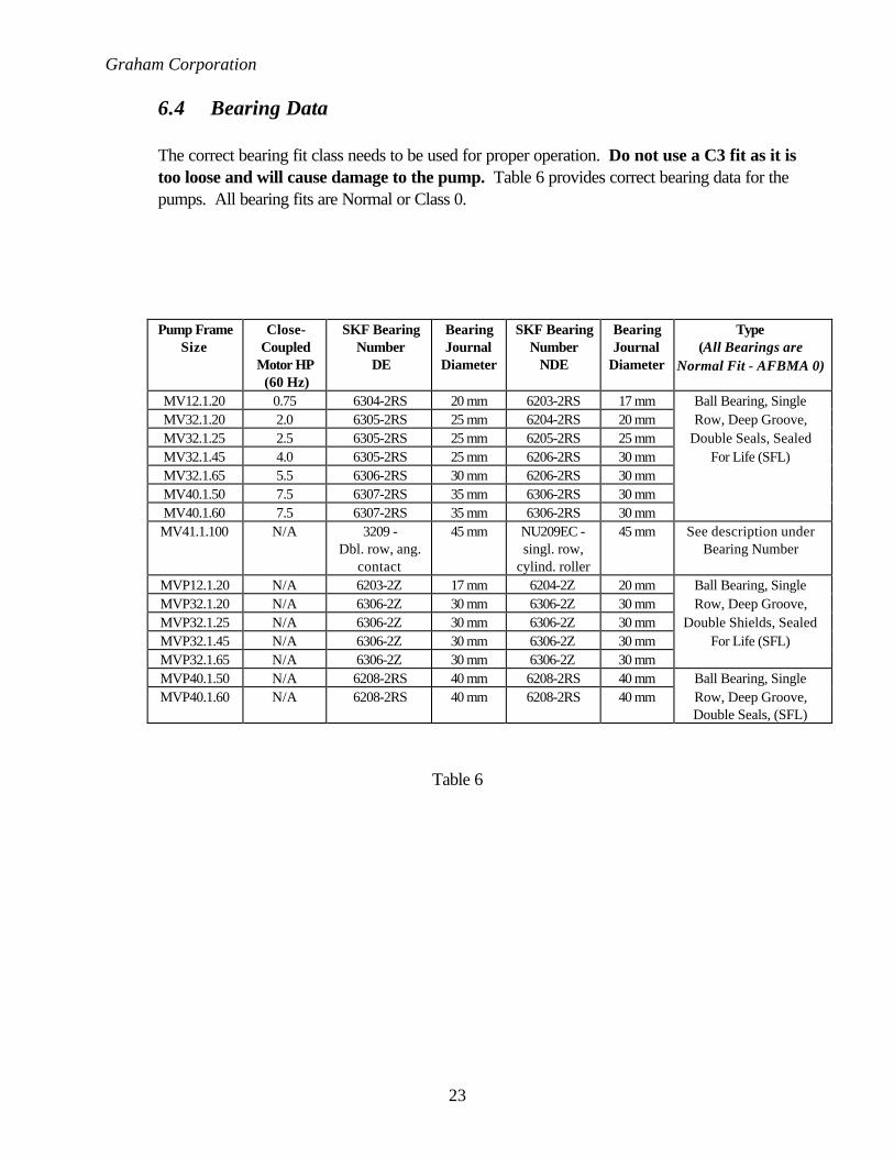
6.4 Bearing Data
The correct bearing fit class needs to be used for proper operation. Do not use a C3 fit as it istoo loose and will cause damage to the pump. Table 6 provides correct bearing data for thepumps. All bearing fits are Normal or Class 0.
Pump FrameSize
Close-Coupled
Motor HP(60 Hz)
SKF BearingNumber
DE
BearingJournal
Diameter
SKF BearingNumber
NDE
BearingJournal
Diameter
Type(All Bearings are
Normal Fit - AFBMA 0)
MV12.1.20 0.75 6304-2RS 20 mm 6203-2RS 17 mm Ball Bearing, SingleMV32.1.20 2.0 6305-2RS 25 mm 6204-2RS 20 mm Row, Deep Groove,MV32.1.25 2.5 6305-2RS 25 mm 6205-2RS 25 mm Double Seals, SealedMV32.1.45 4.0 6305-2RS 25 mm 6206-2RS 30 mm For Life (SFL)MV32.1.65 5.5 6306-2RS 30 mm 6206-2RS 30 mmMV40.1.50 7.5 6307-2RS 35 mm 6306-2RS 30 mmMV40.1.60 7.5 6307-2RS 35 mm 6306-2RS 30 mmMV41.1.100 N/A 3209 -
Dbl. row, ang.contact
45 mm NU209EC -singl. row,
cylind. roller
45 mm See description underBearing Number
MVP12.1.20 N/A 6203-2Z 17 mm 6204-2Z 20 mm Ball Bearing, SingleMVP32.1.20 N/A 6306-2Z 30 mm 6306-2Z 30 mm Row, Deep Groove,MVP32.1.25 N/A 6306-2Z 30 mm 6306-2Z 30 mm Double Shields, SealedMVP32.1.45 N/A 6306-2Z 30 mm 6306-2Z 30 mm For Life (SFL)MVP32.1.65 N/A 6306-2Z 30 mm 6306-2Z 30 mmMVP40.1.50 N/A 6208-2RS 40 mm 6208-2RS 40 mm Ball Bearing, SingleMVP40.1.60 N/A 6208-2RS 40 mm 6208-2RS 40 mm Row, Deep Groove,
Double Seals, (SFL)
Table 6

Graham Corporation
24
Section 7 - Warranty
THE FOLLOWING IS IN LIEU OF ALL WARRANTIES OF GRAHAM EXPRESSED OR IMPLIEDAND ALL IMPLIED WARRANTIES, INCLUDING BUT NOT LIMITED TO ANY IMPLIEDWARRANTY OF MERCHANTABILITY OR FITNESS FOR A PARTICULAR PURPOSE, AND/ORANY OTHER OBLIGATION ON THE PART OF GRAHAM ARE HEREBY EXCLUDED:
Graham, except as otherwise provided, warrants goods of its own manufacture against faulty workmanshipor the use of defective materials, under normal use and service, and that such goods will conform to mutuallyagreed upon written specifications, drawings, and is guaranteed to meet specified performance requirements,for a period of twelve (12) months from date of shipment of the goods from the factory.
Graham assumes no responsibility for deterioration of the equipment due to corrosion, erosion, or flowinduced tube vibration, or for fouling, maintenance problems or any other causes not specifically coveredunder the foregoing warranty. The sole remedy of Buyer with respect to any part not conforming to anywarranty of Graham shall be the repair or, at Graham’s option, replacement of any defective part at thepoint of manufacture, Buyer assuming all costs of removal, shipping, and reinstallation, provided thatimmediate written notice of the defect has been given to Graham, and Graham shall not be liable for anyother expenses incurred because of failure of any part to meet Graham’s warranty, nor for any special,indirect or consequential damages. Material returned to Graham’s factory without its written consent willnot be accepted. No back charges will be honored without Graham’s advance approval of the work to beperformed. Graham’s liability on any claim of any kind, including negligence, for any loss or damage arisingout of, connected with, or resulting from this transaction, or the design, manufacture, sale, delivery, resale,installation, technical direction of installation, inspection, repair, operation, or use of any equipment coveredby or furnished hereunder shall in no case exceed the price paid by Buyer for the equipment. Graham alsodisclaims all liability, whether in contract, tort, warranty, or otherwise, to any party other than the Buyer.
In the event the pumps are altered or repaired by any person or entity other than Graham, without writtenapproval by Graham, all warranties are void. Bearings and shaft seals are warranted only to the extent of,and pursuant to, the original manufacturer's warranty

Graham Corporation
25
Appendix A
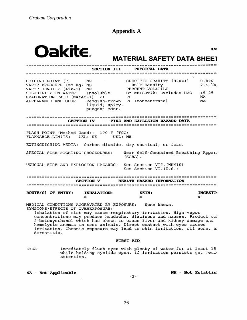
Graham Corporation
26
Appendix A

Graham Corporation
27
Appendix A

Graham Corporation
28
Appendix A

Graham Corporation
29
Appendix B
RETURN MATERIAL AUTHORIZATION FORM
TO: Pump Service Department Date:
FROM:
RMA Number:
This form must be filled out completely before any work will be started on theequipment being returned. This is to ensure the safety of all Graham employees
who may come in contact with this equipment.
MSDS (Material Safety Data Sheet) must be included for all material handled by theequipment. Work on the equipment will be held pending receipt of the MSDS.
The equipment must be cleaned prior to shipping back to Graham. Equipmentreturned in an unsatisfactory condition will be returned to the sender for cleaning.
Customer Data
Customer: Contact Person:
Mailing Address: Phone Number:
Fax Number:
Graham Equipment Information
Graham Serial Number:
Equipment Being Returned:
Reason for Return:
Material Handled by Equipment:
Send equipment and MSDS sheets to the address above, Attn.: Pump Service Dept.This form is to be filled out by Graham (Batavia) personnel only. RMA forms filled out by agents
and customers will not be accepted!
S
MA
PL
E