Embed Size (px)
Citation preview

General Disclaimer
One or more of the Following Statements may affect this Document
This document has been reproduced from the best copy furnished by the
organizational source. It is being released in the interest of making available as
much information as possible.
This document may contain data, which exceeds the sheet parameters. It was
furnished in this condition by the organizational source and is the best copy
available.
This document may contain tone-on-tone or color graphs, charts and/or pictures,
which have been reproduced in black and white.
This document is paginated as submitted by the original source.
Portions of this document are not fully legible due to the historical nature of some
of the material. However, it is the best reproduction available from the original
submission.
Produced by the NASA Center for Aerospace Information (CASI)
https://ntrs.nasa.gov/search.jsp?R=19670030958 2019-06-08T17:01:16+00:00Z
X-552-64-20
l
0
W_U
cca-
0a0
MANNED SPACE FLIGHT NETWORKPREMISSION TEST AIRCRAFT
SYSTEMS DESCRIPTION
^_ U
Li
o LU JANUARY 31, 1964cca.
UO
COPY7 i334
;^ ; : ti CE11TER
r•
TIV74k-sng$300
GODDARD SPACE FLIGHT CENTERGREENBELT, MD.
O N67 -40287,(ACCESSION NUMBER)
~ (PAGES)J
^^/jam)
(NASA CR OR TMX Oft AD NUMBER)
(THRU)
(CODEr,7(CA-1EGORY)

^L
e
fif
V
T
NASA 2 0
V
r
X-552-64-20
MANNED SPACE FLIGHT NETWORK
PREMISSION TEST AIRCRAFT
SYSTEMS DESCRIPTION
JANUARY 31, 1964
This publication supersedes X-550-63-157 dated August 1, 1963
Prepared by
MANNED PLIGHT OPERATIONS DIVISION
MANNED FLIGHT OPERATIONS BRANCH
CODE 552

CONTENTS
Section
P_ age
I INTRODUCTION 1
II FUNCTIONS OF INSTRUMENTED AIRCRAFT 2
III AIRCRAFT EQUIPMENT ARRANGEMENT 4
IV TELEMETRY SYSTEM 7
V COMMAND SYSTEM 20
VI TRACKING SYSTEM 29
VII AIR/GROUND VOICE SYSTEM 32
ii
7
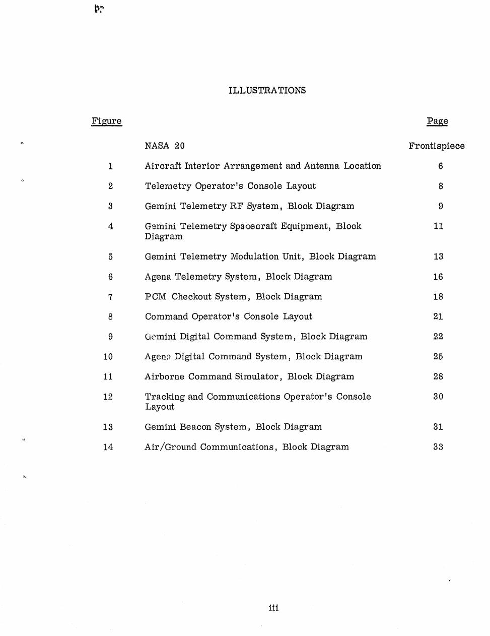
ILLUSTRATIONS
Figu, re Page
NASA 20 Frontispiece
1 Aircraft Interior Arrangement and Antenna Location 6
2 Telemetry Operator's Console Layout 8
3 Gemini Telemetry RI'' System, Block Diagram ;)
4 Gemini Telemetry Spacecraft Equipment, Block 11Diagram
5 Gemini Telemetry Modulation Unit, Block Diagram 13
6 Agena Telemetry System, Block Diagram 16
7 PCM Checkout System, Block Diagram 18
8 Command Operator's Console Layout 21
9 Gemini Digital. Command System, Block Diagram 22
10 Ager" Digital Command System, Block Diagram 25
11 Airborne Command Simulator, Block Diagram 28
12 Tracking and Communications Operator's Console 30Layout
13 Gemini Beacon System, Block Diagram 31
14 Air/Ground Communications, Block Diagram 33
40
iii

SECTION I
INTRODUCTION
The purpose of this document is to serve as a guide for familiarizing tech-
nically oriented personnel with the instrumentation systems that are aboard the
two C-121G Super Constellation aircraft on permanent loan to NASA from the
Air Force. The electronic systems described in this document are used to testthe Manned Space Flight Network's capability to support Gemini/Agena missions.
It is planned that Apollo spacecraft equipment will eventually be installed
in the aircraft to test the Apollo Network, but this equipment is not discussed
herein. However, when major equipment changes are made to the aircraft',-;;instrumentation, this document will be revised.
A
R
1

e
1.
BLANK PAGEv

SECTION II
FUNCTIONS OF THE INSTRUMENTED AIRCRAFT
V#
The aircraft are initially used to check compatibility between the now ground
systems and corresponding spacecraft systems, which are engineering or pro-duction prototypes of spacecraft hardware. The compatibility tests take place as
soon as the first ground systems are installed and operational so that adequate
time will remain for any necessary changes to ground equipment before world-wide deployment of station equipment.
Following the initial compatibility tests, the aircraft are used to completelycheckouteach new or modified station in the network. After thorough individual
system checkouts, the aircraft simulates a spacecraft pass to test the perform-
ance of the entire system so that all interaction between systems may be observed.Complete station checkout is expected to require three to six weeks.
After these acceptance tests are completed, an on-station personnel trainingprogram begins. If time allows, the M&O personnel training may start at each
station as soon as the equipment checkout is complete. It is planned that each
station will be visited by one of the aircraft about every three months to conduct
training missions and evaluation tests.
Since most stations get no practice in tracking vehicles between actual mis-sions, it is desirable to evaluate tb:; equipment and provide personnel training
64
missions. The evaluation tests are a condensed version of the acceptance
tests, plus a special series of training flights. The training flights are completesimulated missions, including DST's/BST's, abbreviated countdown, and all
incoming and outgoing messages. The aircraft flies a flight plan simulating asclosely as possible an actual pass and, with the exception of radar range, dupli-
cates all pertinent electrical characteristics of the spacecraft.
At first normal passes are made. Then, as operator proficiency increases,
various spacecraft and ground station failures are simulated giving the M&O
personnel an opportunity to exercise emergency procedures and backup modes
of operation under "actual" flight conditions.
2

In the past, routine aircraft evaluation tests of Mercury stations almost
always resulted in some firm recommendations for improving equipment or
operational performance. With the increased complexity of ground station
equipment, these tests become increasingly more valuable as a method fortraining and for evaluating performance,
le
Y
3
SECTION III
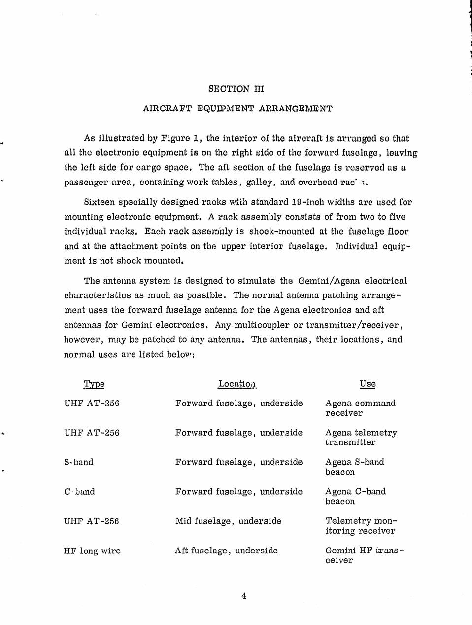
AIRCRAFT EQUIPMENT ARRANGEMENT
As illustrated by Figure I I the interior of the aircraft is arranged so thatall the electronic equipment is on the right side of the forward fuselage, leaving
the left side for cargo space. The aft section of the fuselage is reserved as a
passenger area, containing work tables, galley, and overhead rac* 'r,.
Sixteen specially designed racks w-1 1ch standard 19-inch widths are used formounting electronic equipment. A rack assembly consists of from two to five
individual racks. Each rack assembly is shock-mounted at the fuselage floorand at the attachment points on the upper interior fuselage. Individual equip-
ment, is not shock mounted,
The antenna system is designed to simulate the Gemini/Agena electricalcharacteristics as much as possible. The normal antenna patching arrange-ment uses the forward fuselage antenna for the Agena electronics and aft
antennas for Gemini electronics. Any multicoupler or transmitter /receiver,
however, may be patched to any antenna. The antennas, their locations, andnormal uses are listed below:
TV]2 Location Use
UHF AT-256 Forward fuselage, underside Agena commandreceiver
UHF AT-256 Forward fuselage, underside Agena telemetrytransmitter
S,band Forward fuselage, underside Agena S-bandbeacon
C - band Forward fuselage, underside Agena C-bandbeacon
UHF AT-256 Mid fuselage, underside Telemetry mon-itoring receiver
HIP long wire Aft fuselage, underside Gemini HF trans-ceiver
4
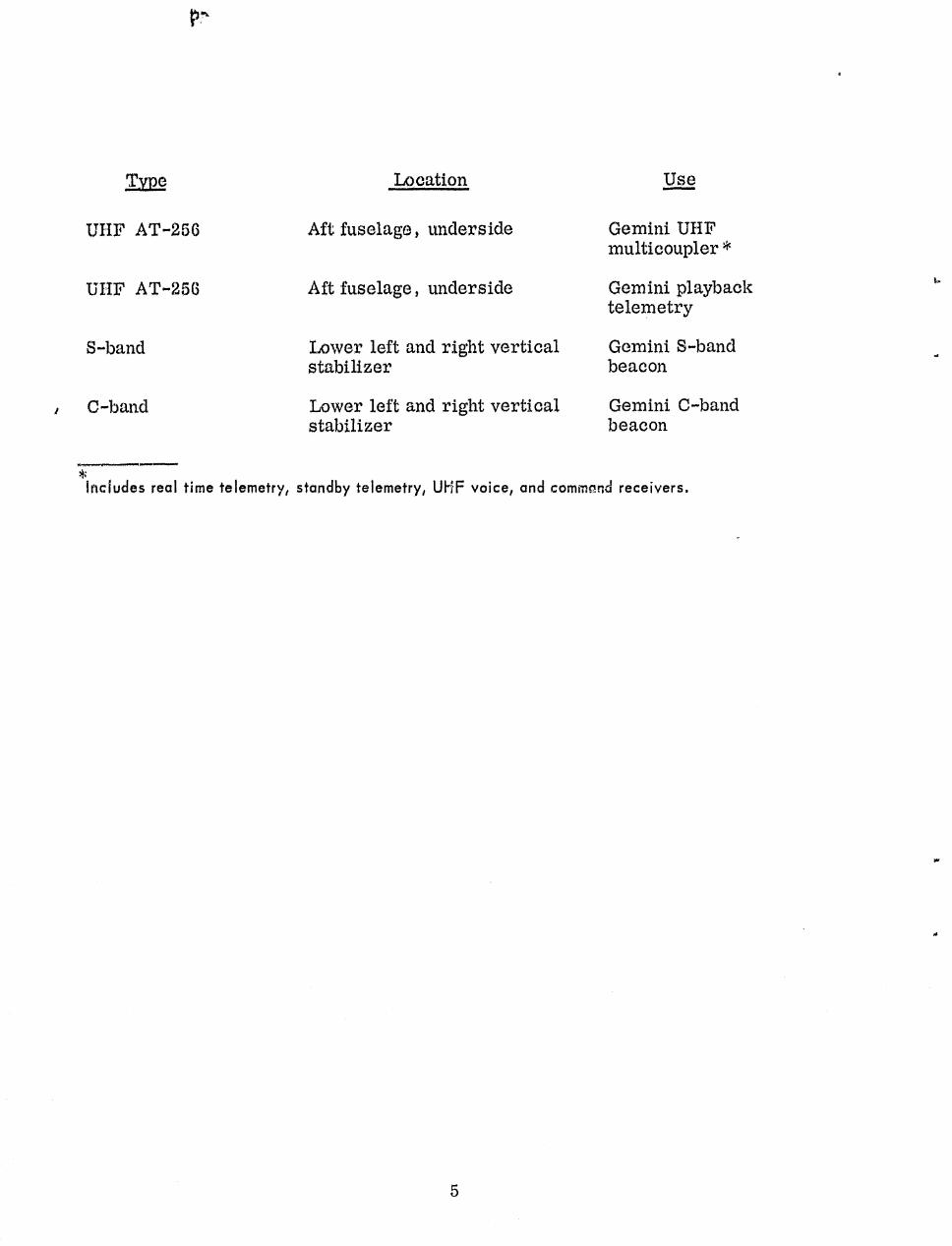
P^ ft
T,Vp
UIIF AT-256
UIIF AT-256
S--band
I C-band
Location
Aft fuselage, underside
Aft fuselage, underside
Lower left and right verticalstabilizer
Lower left and right verticalstabilizer
Use
Gemini UHFmulticoupler
Gemini playbacktelemetry
Gemini S-bandbeacon
Gemini C-bandbeacon
t.
Includes real time telemetry, standby telemetry, UHF voice, and command receivers.
0
5

_HFLEAD-IN
UHFAT-256
V V .
AT-256 FLUSHMOUNT
NOTE:BEACON ANTENNAS MOUNTEION LEFT AND RIGHTSTABILIZERS
S BANDFLUSHMOUNT
CURTAIN -GALLEY
TRONICS EOUiPMENT7:jt
m
PASSENGER AREA
CARGO AREA
M
CREW BUNKS
FORWARD
r
NOTE COLD STORAGE
AIRCRAFT NAUCCOM ANTENNASNOT SHOWN
0.
w
Figure 1. Aircraft Interior Arrangement and Antenna Locations
6

BLANK PtrGE
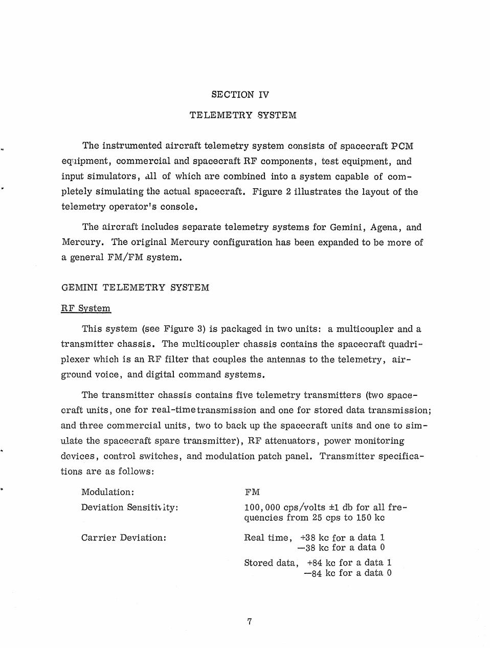
SECTION IV
Q
TELEMETRY SYSTEM
The instrumented aircraft telemetry system consists of spacecraft PCMequipment, commercial and spacecraft RF components, test equipment, and
input simulators, all of which are combined into a system capable of com-
pletely simulating the actual spacecraft. Figure 2 illustrates the layout of thetelemetry operator's console.
The aircraft includes separate telemetry systems for Gemini, Agena, and
Mercury. The original Mercury configuration has been expanded to be more ofa general FM/FM system.
GEMINI TELEMETRY SYSTEM
RF System
This system (see Figure 3) is packaged in two units: a multicoupler and atransmitter chassis. The multicoupler chassis contains the spacecraft quadri-
plexer which is an RF filter that couples the antennas to the telemetry, air-
ground voice, and digital command systems.
The transmitter chassis contains five telemetry transmitters (two space-crafi: units, one for real-time transmission and one for stored data transmission;
and three commercial units, two to back up the spacecraft units and one to sim-
ulate the spacecraft spare transmitter) , RF attenuators , power monitoring
devices, control switches, and modulation patch panel. Transmitter specifica-
tions are as follows:
Modulation: FMDeviation Sensiti,,Yty:
Carrier Deviation:
100, 000 cps/volts f1 db for all fre-quencies from 25 cps to 150 kc
Real time, +38 kc for a data 1—38 kc for a data 0
Stored data, +84 kc for a data 1—84 kc for a data 0
7

r
28VDC POWER SUPPLY
BLOWER
BIT
SYNCHRONIZER
GROUPSYNCHRONIZER
WORD SELECTOR
BINARY DISPLAY/PATCH PANEL
D/A CONVERTOR
PCM SIMULATOR
BLOWER
GEMINI TIM
PATCH PANEL
OSCILLOSCOPE
GEMINI TIMINPUT SIMULATOR
BI-LEVEL SIMULATOR
COMPUTER WORDGENERATOR
AC POWER CONTROL
RF PATCH/COUPLER
T/M RCVR RF PATCH PANEL
TIM
RECEIVER
GEMINI TIM RF
INTERCOM
AC POWER CONTROL
COUNTER
EKG GENERATOR
DIGITAL VOLTMETER
LOW FREOUENCYFUNCTION GENERATOR
VACUUM TUBE
VOLTMETER
AUDIO OSCILLATOR
28VOC POWER SUPPLY
28VDC POWER SUPPLY
BLOWER
MERCURY TIM
XMTR ASS'Y
TMI
DEECO
SUBCARRIER
ANALYZER
MERCURY TIM
MOD. UNIT
TMI
POWER SUPPLY
28 VDC
REGULATOR
BLOWER
BLOWER I BLOWER
(REAR OF RACK) i i (REAR OF RACK)
CHAIR AND KNEE WELL AREA
Figure 2. Telemetry Operator's Console Layout
8

Tc
AUXILIARY PCM SPACECRAFT
INPUT SIMULATOR PROGRAMMERINPUT INPUTS
Figure 3. Gemini Telemetry RF System, Block Diagram
9
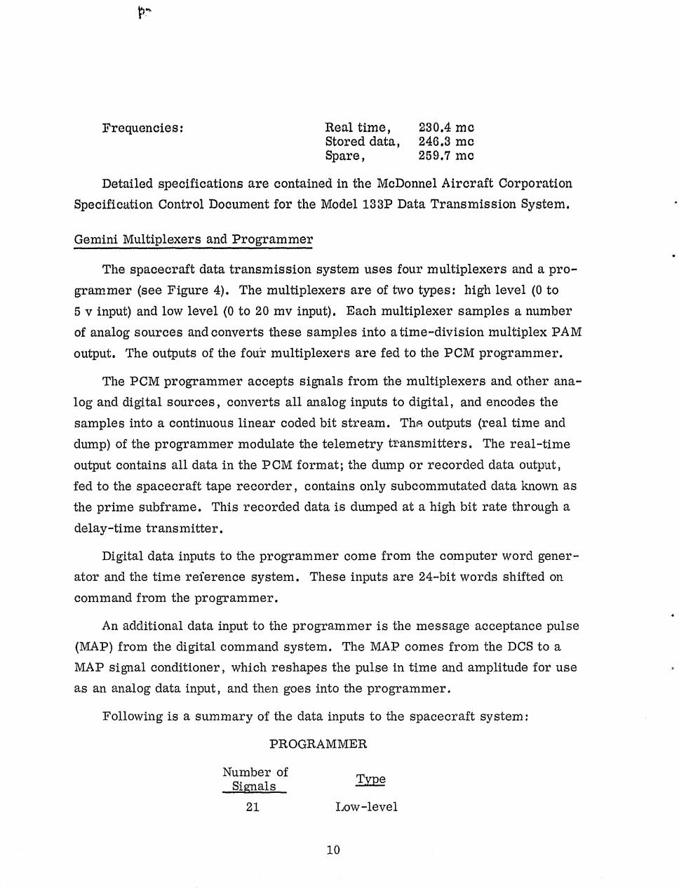
Frequencies: Real time, 230.4 meStored data, 246.3 meSpare, 259.7 me
Detailed specifications are contained in the McDonnel Aircraft CorporationSpecification Control Document for the Model 133P Data Transmission System.
Gemini Multiplexers and Programmer
The spacecraft data transmission system uses four multiplexers and a pro-grammer (see Figure 4). The multiplexers are of two types: high level (0 to5 v input) and low level (0 to 20 m y input). Each multiplexer samples a numberof analog sources and converts these samples into atime-division multiplex PAMoutput. The outputs of the four multiplexers are fed to the PCM programmer.
The PCM programmer accepts signals from the multiplexers and other ana-log and digital sources, converts all analog inputs to digital, and encodes thesamples into a continuous linear coded bit stream. The outputs (real time anddump) of the programmer modulate the telemetry t ransmitters. The real-timeoutput contains all data in the PCM format; the dump or recorded data output,fed to the spacecraft tape recorder, contains only subcommutated data known asthe prime subframe. This recorded data is dumped at a high bit rate through adelay-time transmitter.
Digital data inputs to the programmer come from the computer word gener-ator and the time reference system. These inputs are 24-bit words shifted oncommand from the programmer.
An additional data input to the programmer is the message acceptance pulse(MAP) from the digital command system. The MAP comes from the DCS to aMAP signal conditioner, which reshapes the pulse in time and amplitude for useas an analog data input, and then goes into the programmer.
Following is a summary of the data inputs to the spacecraft system:
PROGRAMMER
Number of TypeSignals
21 Low-level
10
Li ^ a^

ANALOG DATA
LOW LEVEL
MULTIPLEXER
a6d ~Z $4 ^
Q
TELEMETRY
PATCH
PANEL
LOW LEVEL
MULTIPLEXER
HIGH LEVEL
MULTIPLEXER
REAL TIME DATA
PROGRAMMER
DELAYED TIME DATATO
TRANSMITTERS
CONTROL
HIGH LEVEL
MULTIPLEXER SPACECRAFT
TAPE RECORDER
COMPUTERWORD
t GENERATOR
Figure 4. Gemini Telemetry Spacecraft Equipment, Block Diagram
11

Number ofSignals
444024
Type
Nigh-levelBi-levelDigital
00
PROGRAMMER (Continued)
LOW-LEVEL MULTIPLEXER (2 units)64
Low-level
HIGH-LEVEL MULTIPLEXER (2 units)64 High-level48 Bi-level32 Bi-level pulse
All analog multiplexer and programmer inputs listed above are connected tothe patch board where a maximum of 25 spacecraft inputs may be patched to anysimulated source in the telemetry modulation unit (TMU).
Telemetry Modulation Unit
The purpose of the telemetry modulation unit is to provide simulated trans-ducer outputs and complete patching flexibility so that the telemetry format anddata output of any given Gemini spacecraft may be closely simulated. The TMUconsists of two sub-units: the input simulator chassis and the input patch chassis(see figure 5).
The input simulator provides precision analog voltages in the high-level range(0-5 v) and low-level range (0-20 mv). Any signal source may be set at any levelwithin these limits. Precision voltmeters are used. to determine the exact inputlevel.
A five-level stepping function generator may be used with any group of fivehigh and/or low level analog sources.
The function generator's output will be a voltage that steps between any fivepre-set levels. Any number of spacecraft inputs may be patched to the functiongenerator output.
12

6,-LEVELSOURCES
LEVELSTEPPING
GENERATOR
LOW FREQUENCYDATA SIMULATOR
EKGSIMULATOR
20NIGH LEVEL
SOURCES
TELEMETRY
PATCH
PANEL
APPROX
400
OUTPUTS TO
$FACECRAFT
TELEMETRY
SYSTEtA
10
LOW LEVEL
SOURCES
81-LEVELDATA
FROM DOS
Figure 5. Gemini Telemetry Modulation Unit, Block Diagram
13
^r
P
ON
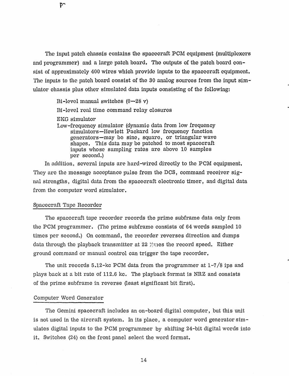
The input patch chassis contains the spacecraft PCM equipment (multiplexers
and programmer) and a large patch board. The outputs of the patch board con-
sist of approximately 400 wires which provide inputs to the spacecraft equipment,
The inputs to the patch board consist of the 30 analog sources from the input sim-
ulator chassis plus other simulated data inputs consisting of the following:
13i-level manual switches (0-28 v)
Bi-level real time command relay closures
EKG simulatorLow-frequency simulator (dynamic data from low frequency
simulators—Howlett Packard low frequency functiongenerators—may be sine, square, or triangular waveshapes. This data may be patched to most spacecraftinputs whose sampling rates are above 10 samplesper second.)
In addition, several inputs are hard-wired directly to the PCM equipment.
They are the message acceptance pulse from the DCS, command receiver sig-
nal strengths, digital data from the spacecraft electronic timer, and digital data
from the computer word simulator.
Spacecraft Tape Recorder
tape reCmIrlin-t, records the prime subframe data only fromW____ __ V-- _V __
the PCM programmer. (The prime subframe consists of 64 words sampled 10
times per second.) On command, the recorder reverses direction and dumps
data through the playback transmitter at 22 ' nes the record speed. Either
ground command or manual control can trigger the tape recorder.
The unit records 5.12-kc PCM data from the programmer at 1-7/8 ips and
plays back at a bit rate of 112.6 kc. The playback format is NRZ and consists
of the prime subframe in
reverse (least significant bit first).
Computer Word Generator
The Gemini spacecraft includes an on-board digital computer, but this unit
is not used in the aircraft system. In its place, a computer word generator sim-
ulates digital inputs to the PCM programmer by shifting 24-bit digital words into
it. Switches (24) on
the front panel select the word format.
14

AOT",,N, rA TELEMETRY SYSTEM (See Figure 6)
Rj" System
The Agena RR system consists of four transmitters, a multicoupler, RFattenuators , power monitoring devices, modulation patch panel, and controlswitches. The transmitters are in two grotips—real time and delay time—witha spacecraft and commercial transmitter in each group. Specifications are asfollows:
Frequencies: Real time, 240.2 meStored data, 248.6 me
Deviation: Real time, —21 kc for a data 1+21 kc for a data 0
Stored data, —45 kc for a data 1•45 kc for a data 0
Agena PCM Data System
The Agena multiplexer equipment consists of two 128-channel multiplexers,PCM encoder, and telemetry control unit. The multiplexers accept high-levelanalog data and convert it to a PAM pulse train. Multiplexer outputs are ledto the PCM encoder, which converts the PAM pulse train to serial encodedPCM. The PCM encoder output is fed to the telemetry control unit along withdirect digital data from the command system and pulse analog data from theturbine speed counter simulator. The control unit serializes its various inputsand modulates the TLM transmitters with NRZ PCM data.
Data rates are 16,384 bps for real time data and 65,536 bps for stored data.
'A
Telemetry Modulation Unit
The Agena TMU consists of 20 high-level analog sources, 64 bi-levelswitches, a function generator, and patch panel. Any multiplexer input may bepatched to any source through the patch panel. The function generator may alsobe used to provide automatic level steps botween any five levels for multiplexerinputs. Command status signals can also be patched to spacecraft inputs.
15

vwk
Figure 6. Agena Telemetry System, Block Diagram
16
t
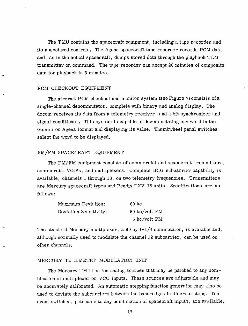
The TMU contains the spacecraft equipment, including a tape recorder andits associated controls. The Agena spacecraft tape recorder records PCM dataand, as in the actual spacecraft, dumps stored data through the playback TLMtransmitter on command. The tape recorder can accept 20 minutes of compositedata for playback in 5 minutes.
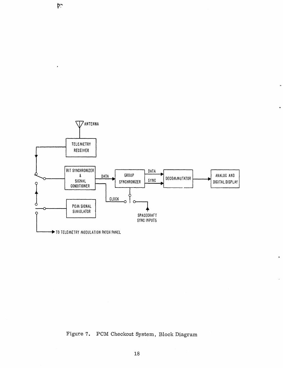
PCM CHECKOUT EQUIPMENT
The aircraft PCM checkout and monitor system (see figure 7) consists of asingle-channel decommutator, complete with binary and analog display. Thedecom receives its data from a telemetry receiver, and a bit synchronizer andsignal conditioner. This system is capable of decommutating any word in theGemini or Agena format and displaying its value. Thumbwheel panel switchesselect the word to be displayed.
FM/FM SPACECRAFT EQUIPMENT
The FM/FM equipment consists of commercial and spacecraft transmitters,commercial VCO's, and multiplexers. Complete IRIG subcarrier capability isavailable, channels 1 through 18, on two telemetry frequencies. Transmittersare Mercury spacecraft types and Bendix TXV-18 units. Specifications are asfollows:
Maximum Deviation: 60 kcDeviation Sensitivity: 60 kc/volt FM
5 kc/volt PM
The standard Mercury multiplexer, a 90 by 1-1/4 commutator, is avaiable and,although normally used to modulate the channel 1.2 subcarrier, can be used on
. other channels.
MERCURY TELEMETRY MODULATION UNIT
The Mercury TMU has ten analog sources that may be patched to any com-
bination of multiplexer or VCO inputs. These sources are adjustable and may
? be accurately calibrated. An automatic stepping function generator may also beused to deviate the subcarriers between the band-edges in discrete steps; Ten
event switches, patchable to any combination of spacecraft input:, are y.j<.^ fable.
17
GROUP'ATA
P
SYNCHRONIZER SYNCDECOMMUTATOR
^^ ANALOG AND
DIGITAL DISPLAY
.v
ANTENNA
TELEMETRY
RECEIVER
^j BIT SYNCHRONIZER
sZ-",o & DATASIGNAL
CONDITIONER LCLOCK
PCM SIGNAL
SIMULATOR
TO TELEMETRY MODULATION PATCH PANE
0-^SPACECRAFT
SYNO INPUTS
b
Figure 7. PCM Checkout System, Block Diagram
XS
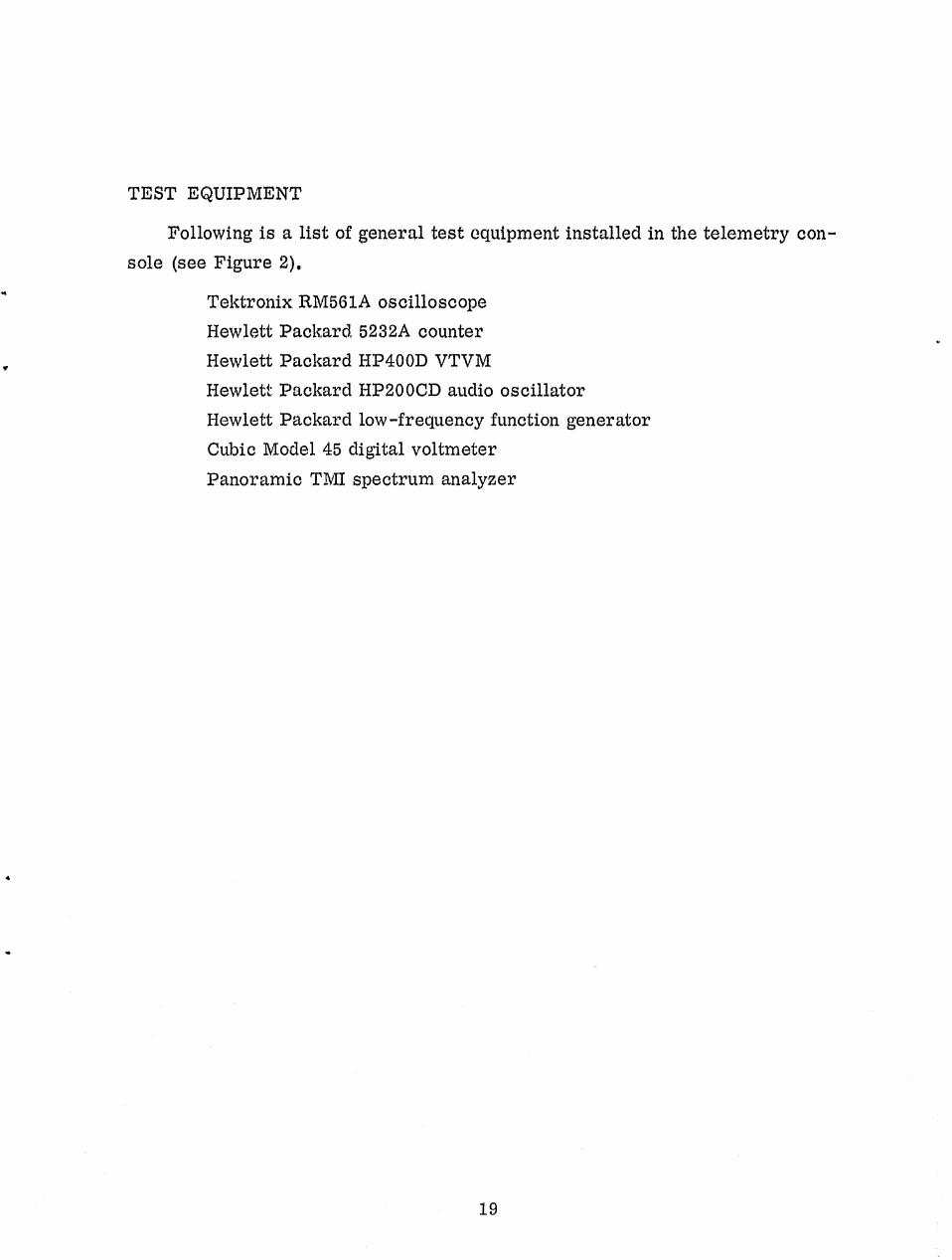
TEST EQUIPMENT
Following is a list of general test equipment installed in the telemetry con-sole (see Figure 2).
Tektronix RM561A oscilloscope
Hewlett Packard, 5232A counterHewlett Packard HP400D VTVM
Hewlet:: Packard HP200CD audio oscillatorHewlett Packard low-frequency function generatorCubic Model 45 digital voltmeter
Panoramic TMI spectrum analyzer
19


SECTION V
COMMAND SYSTEM
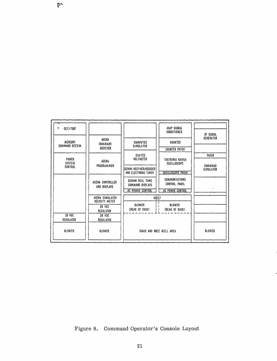
The aircraft command systems consist of actual spacecraft components andaddi^ional peripheral equipment to provide simulation and display capabilities.Figure 8 illustrates the layout of the command operator's console.
GEMINI DIGITAL COMMAND SYSTEM (See Figure 9)
The Gemini system ,z eceives , demodulates, and decodes digital commandssent from the ground station. Decoded messages meeting certain validity cri-teria generate a message acceptance pulse IMA1%) and are routed to the addressedspacecraft system as follows: real time commands (RTC) to the 32 RTC relays,clock commands to the electronic timer, and computer word commands to thesimulated computer (computer response simulator). The MAP is transmitted tothe ground station through the telemetry system along with receiver signalstrengths, RTC command status, and clock readouts from the electronic timer.On-board simulation and display capabilities are explained in the followingequipment descriptions.
RF System
A UHF blade antenna is connected through a quadriplexer, an RIP patchboard, a 0 to 119-db variable attenuator, and power divider to the receiver/decoder.
Receiver/Decoder
This is an actual spacecraft unit consisting of the following:
Two superhet FM receiversPhase lock loop (detects 1-kc sync tone)Integrating type phase detector (detects sub-bits from 2-kc PSK tone)Info bit detector (detects correct sub-bit codes)Command message decoder (logic circuitry)Temporary storage register
It
20
01
COMPUTERSIMULATOR
DIGITECVOLTMETER
GEMINI RECFIVER/DECODERAND ELECTRONIC TIMER
GEMINI REAL TIME
COMMAND DISPLAYS
AC POWER CONTRO L
CET/TORF
MERCURYCOMMAND SYSTEM
POWER
SYSTEMCONTROL
28 VOC
REGULATOR
BLOWER
AGENA
COMMAND
RECEIVER
AGENA
PROGRAMMER
ACENA CONTROLLER
AND DISPLAYS
AGENA SIMULATEDVELOCITY METER
28 VDC
REGULATOR
28 VDC
REGULATOR
BLOWER
MAP SIGNALCONDITIONER
COUNTER
COUNTER PATCH
TEKTRONIX RM45AOSCILLOSCOPE
OSC ILLOSCOPE A
COMMUNICATIONS
CONTROL PANEL
AC POWER CON TROL
SI^E^f _y
BLOWER j BLOWER
(REAR OF RACK) I i (REAR OF RACK).. -- -- 1L -^-- ---
CHAIR AND KNEE WELL AREA
RF SIGNALGENERATOR
PATCH
COMMANDSIMULATOR
BLOWER
N
w
Figure 8. Command Operator's Console Layout
21

M-1 "
FP- 1 4
w acac
C.7
CL.> L" sz!s 9NC as I.- -C 2M0::me C->Q: C^ LAJC.2,.0 LWUJ L" C3^ —J
VJW
CeLU
CL.
4.0CD
WLAJ Ln Q-
L
C--A -C CDcz. C=
vUA
CD W cr_LWOvw We
.-J='t I-- LW_j LOD.V7
O
n 10
q,
OD
O
LU
WO t2zi
Figure 9. Gemini Digital Command System, Block Diagram
22

40
try,
Display Unit
This unit includes the 32 RTC relays (spacecraft equipment) and 32 associ-ated lamp displays to indicate the SET or RESET position of each relay. The
relay contact closures are a7ailable for on-board operational functions (beacons V
ON-OFF, etc.). Switches (32) are provided to allow manual set or reset of eachrelay in the aircraft. An "astro lamp' s and switch are included. This lamp isdriven by a latching relay in the decoder, and it signifies that data is beingtransferred to the electronic timer or computer. The switch is used to resetthe relay.
aThe MAP di%play is a flashing neon lamp driven by the MAP signal condi-
tioner and provides an on-board display of correct command receipt. The MAPinhibit switch inhibits the MAP from passing to the TLM. Thus the aircraftcommand operator can require the ground station to retransmit a given com-mand by inhibiting the MAP. This will allow an exercise of the automatic retrans-mit capability of the ground station.
Spacecraft Electronic Timer
This unit contains the registers, arithmetic units, and clock to count downTTG to Tr (time to go to time of retrofire) and TTG to Tx (time to go to equi.p-ment reset), and to count up capsule elapsed time (CET) from liftoff. The 'LTGregisters can be updated from the ground through the DCS. Data transfer oc-curs in the following manner: the decoder sends a ready signal to the addressedsystem (electronic timer in this case) indicating that it has a data word in stor-age, ready for transfer. The system responds with a series of transfer pulses,and the data is shifted from the decoder to the system. TTG to Tr and CET areread out to the ground station through the PCM TLM. Relay contact closuresoccur at Tr-5 min., Tr-30 sec., Tr, and Tx. The relay closure at Tx maybe used to reset selected RTC (real time command) relays.
Electronic Timer Display
This unit is used to read out and display data from the electronic timer. A24-bit binary display of either CET or TTG to Tr is provided. This displayallows the aircraft command operator to view the same clock information that
23
would be read out through the digital computer in the actual spacecraft. Lampdisplays of Tr--5 min., Tr--30 see., Te, and Tx event times are also provided.The countdown of the electronic timer is controlled by switches on this unit.The clock can be inhibited from the aircraft to require an update from the ground
A
station through the DCS.
IVComputer Response Simulator
This unit allows the ground station to transmit computer words and receiveverification of their receipt, although an actual computer is not on-board theaircraft.
The simulator receives the computer-ready signal from the decoder andresponds with 24 transfer pulses. This allows the decoder register to becleared and causes the generation of a MAP for computer commands.
DCS/PCM InterfaceThe airborne DCS supplies the following signals to the PCM TLM for
transmission:
TTG to Tr and CET (digital)ITC status (analog)MAP (analog)Receiver signal strengths (analog)
The MAP signal conditioner is provided to shape the MAP into a pulse ofsuitable magnitude and length for the PCM TLM system.
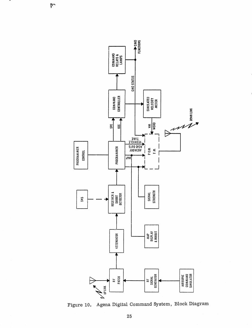
A GENA COMMAND SYSTEM
The Agena cornmand system (see figure 10) receives, demodulates, anddecodesdigital commands addressed to the Agena target vehicle. As with the Gemini com-mand system, MAP' s , generated when messages have been accepted from the groundstation, are routed to the Agena telemetry for transmission back to the groundstation to indicate the acceptance of messages by the Agena command system.Commands are of two types: real time commands (RTC) and stored programcommands (SPC). RTC's are actuated immediately upon receipt, while SPC's
24
o sn
yr"! 1 t^'
'°G Rn g„
8 L J4i CC
to
+C
hO
Ca
zC w s.^. ►m a
o "' w2e
C> CIC
3
3w11 I310IH33 A i
cc lino av38 idaow3w
ccQ
aaw^.
IQ.Q.
L6C.0^- z x0
U7 y m c~a CO W
V H W
a ^'
IVft
g
M
x J a_oa
Q .^ H Z_W1+
IY W Q
Uj
V Q 1-` 0.. Q
a Q S ^" J
C1 N Z Q
W .iG2 C.? U NJQ.
Figure 10. Agena Digital Command System, Block Diagram
25
Z
(RTC's with a time label attached) are stored in a 64-word memory in the pro-gr, ammer and actuated at the coincidence of vehicle time with the SPC time label.
RF System
A UHF blade antenna is connected through an RF patchboard and a 9 to
It119-db variable attenuator to the spacecraft receiver.
Receiver/Sub-bit
This is an actual spacecraft component that recei Ais and demodulates theRF input, and supplies a sub-bit output to the programmer.
Programmer
The spacecraft programmer converts the sub-bit train into info-bits anddecodes the message.
Command Controller
This unit is actuated by the RTC or SPC actuation signal and supplies outputsto various relays for on-off functions. The TLM modulation buss is also switchedinternally by the controller.
Displays
On-board displays consist of the following: Agena command display (lampsindicating on-off status) , MAP inhibit display, and receiver signal strength
4
(DVM).
Simulated Velocity Meter
This unit receives the velocity meter (VM) load ONE and load ZERO com-mands from the controller au, shifts them into a 16-bit register. The VM inter-rogate command then reads this VM word Into another 16-bit register, whichalso has inputs from 16-bit switches so that errors may be introduced into theVM word. An on-board display of the VM word is provided.
26
+ r.-. ate
01
AUXILIARY EQUIPMENT
Airborne Command Simulator
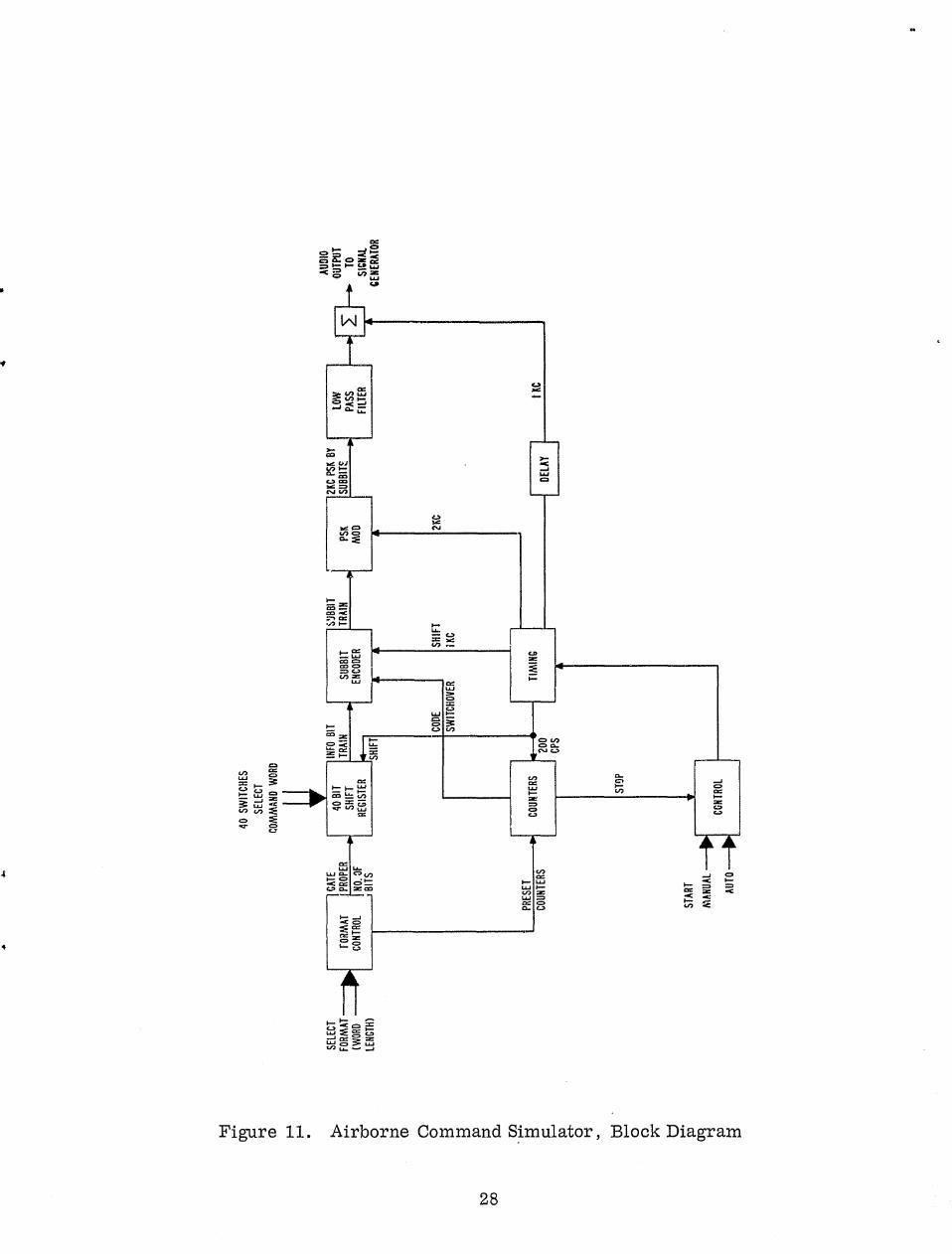
The airborne command simulator (ACS) illustrated in
Figure 11, is pro-
vided to preflight the Gemini and Agena command systems. It consists of a
completely selectable word generator, format selector, patchable sub-bit
encoder, ground station PSIS modulation, and a phase meter. The ACS gen-
erates simulated commands which in turn modulate an
RF signal generator.
The output of the signal generator is then patched into either the Gemini or
Agena command receiver.
The phase meter, by measuring the relative phase shift between the 1- and
2-kc tones of the composite audio signal, is used to align the ACS modulator and
to analyze th(,^,, audio output from the command receivers during flyover. tests.
Test Equipment
Test equipment available ir,cludes a 545A oscilloscope to monitor vari=i
operational test points, a 0- to 100-mv digital voltmeter to monitor receiver
signal strengths, and a counter to count MAP's.
x
a
27
4
G1
Gz ^ 3
N N ^{O C
.r
V' Ov
.°Roza= ^ .-- fi.0 y W
^'acxN W 3 J
Figure 11. Airborne Command Simulator, Block Diagram
28

40,
IVIIII
iR
le
Y.
t.
B`'LAN K
Pf,GE
o ^

SECTION VI
TRACKING SYSTEM
The aircraft is equipped with radar beacons similar to those in the Gemini81
Agena spacecraft. The beacons and associated equipment, are contained inthe tracking and communications operator's console, as shown in Figure 12.
Y There are provisions for four beacons, two C-band and two S-band. Figure 13illustrates the Gemini beacon system. This system arrangement permits radarsimulation of the Gemini spacecraft and Agena target vehicle approaching ren-dezvous or in a docked condition.
The output of each beacon goes through an adjustable 0- to 2.0-microseconddelay circuit so that the radar beacon return may be delayed sufficiently toseparate aircraft skin return from beacon return, A 0- to 50-db ;^tttenuator isinserted in the RF loop for each beacon to permit radar threshold tests. AnRF patchboard is provided to permit patching of beacons to a variety of antennacombinations.
Gemini and Agena Beacon Package
A single chassis houses the Gemini S band and C-band beacons. In addition
to attenuator and delay controls, there are miscellaneous test points and inter-
rogation indications mounted on the chassis front panel.
Rabbit Generator
s
A specially designed rabbit generator is used to provide realistic training
in radar handover procedures. The unit generates a series of pulses that trig-
ger the driver section of the beacon, simulating interrogation by several radars.The effect is to provide an extra return or rabbit to the tracking radar, thus
simulating beacon sharing by two radars. The number of rabbits, repetition rate,
and delay between rabbits is selectable.
Test Equipment
A sufficient amount of test equipment is provided to completely preflight the
beacons. This includes a beacon code simulator that generates a double pulse for
beacon interrogation, a converter and counter, and a dual trace oscilloscope.
29

P7.
FREQUENCY CONVERTER
BECKMAN 7570
TRANSFER
OSCILLATOR
HP 540
SIGNAL
GENERATOR
MARCONI 1066
BLOWER
(BEHIND)
BEACON RF PATCH
BEACON CODE
SIMULATOR
RABBIT
GENERATOR
BEACON ASS'Y
(AGENA)
BEACON ASS'Y
(GEMINI)
AC POWER CONTROL
DC REGULATOR
MICROWAVE
POWER METER
HF T/F
UHF T/F
TEKTRONIX RM17
OSCILLIDSCOPE
COMMUNICATIONS
CONTROL PANEL
AC POWE CO RO
MAGNECORD
TAPE RECORDER
HP 200 CD
OSCILLATOR
AUDIO
DISTRIBUTION
DC REGULATOR
DC REGULATOR
BLOWER
(BEHIND)
BLOWER j I BLOWER
(REAR OF RACK) I I (REAR OF RACK)
CHAIR AND KNEE WELL AREA
AEM NO.8
BLOWER
l BEHIND)
t
Figure 12. Tracking and Communications Operator's Console Layout
30

II ^
t
4
POWER 0 TO5ODB R 0 TO 500B -2008
FROMMONITOR ATTENUATOR PATCH ATTENUATOR COUPLER
AGENA
BEACONS
-3008 -20DB XTAL XTAL -3ODBCOUPLER COUPLER DETECTOR DETECTOR COUPLER
ha-r
S-BANDVALID I 1 C-BAND
BEACONTRACK SCOPE -- - - J
BEACONINDICATOR R1
DISABLE 0-2u SEC RABBIT j 0-2k SEC DISABLERELAY DELAY GENERATOR DELAY RELAY
^I RF CIRCUIT r
Q2 DECODED PULSE OUTPUT
Q3 MODULATOR INPUT
Figure 13. Gemini Beacon System, Block Diagram
t
I
31

^
B 'L 'A N R P A
4
SECTION VII
AIR/GROUND VOICE SYSTEM
Since the UHF and HF frequencies for the Gemini spacecraft are identical to
Mercury frequencies, the Mercury spacecraft hardware is used in the aircraft
to exercise ground station air/ground communications equipment,
The Mercury system is modified to the extent that a second audio center is
provided so that both the air/ground operator and the command operator have the
capability to key either HF or UHF transmitters.
A block diagram of the spacecraft equipment is .shown. in Fi gure 14.
IV
32

S ae
k
A
a
1
do
a+8C gx
W WS
xv ^x^+~[itW
I yK^
OrC S74'ft
J ^ ca.
9C
^
_C^a
+}^Z^
V ry^ ^U i^
K1 S w O I W O ,wry ii:E CpCp
°1^' w r-I
►'4 J
NN
pC I
SIC
y ,—I
ZZ
^ p
Vf=.tSo
^_ W{Y
I. UCc, W
Z°^at
I
n^omND
1 ^ W I11 x -+"^ oNZ
U^aNU 2w^ x xy
1 t 1 i—.— I
SSOS~ SU H
UjJV)W NN
I OCW
> F^OC W= UUW O
4 f
M W
I ^ N IW ZJ o
^ w vr-
oe^ v
S UJ iI
Figure 14. Air/Ground Communications, Block Diagram
33
d'NSC
.0
h