Embed Size (px)
Citation preview

Jogging and Running Aid for the
Blind and Visually Impaired
Final Report
Caroline Flowers, Alyssa Wei, Thomas Trzpit
ENGR110/210: Perspectives in Assistive Technology
Winter 2016
one milemore
Jogging and Running Aid for the Blind and Visually Impaired Page 1
one milemore
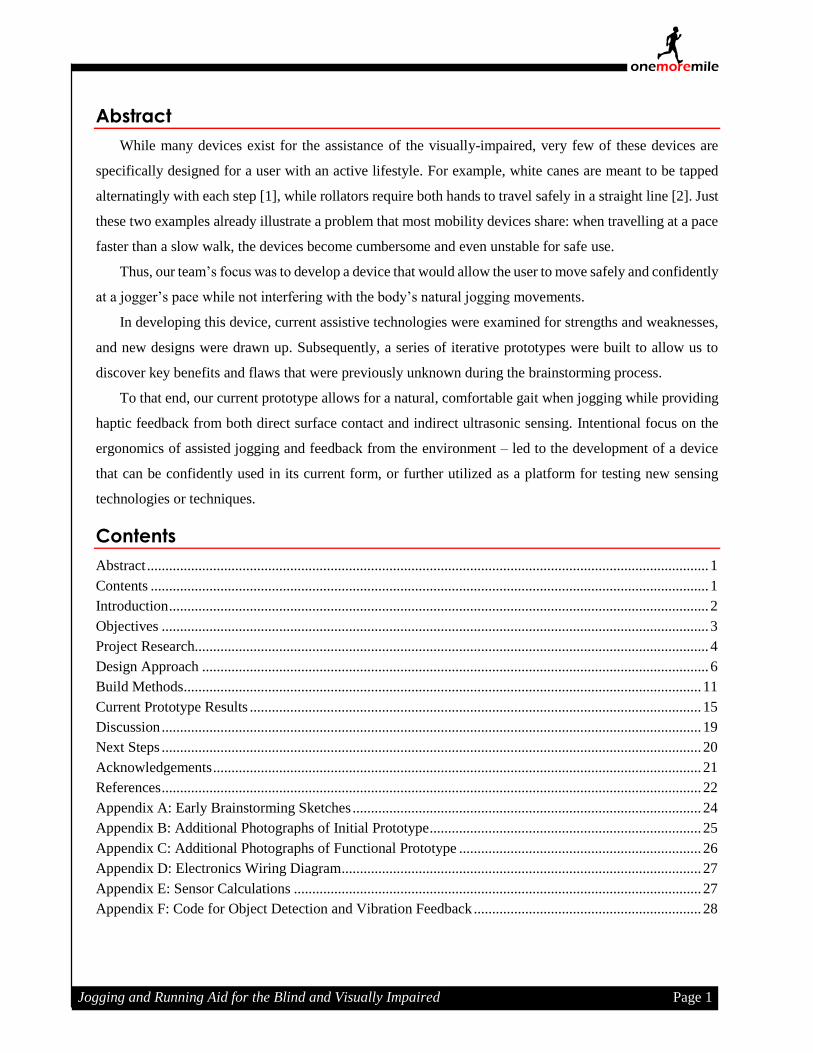
Abstract
While many devices exist for the assistance of the visually-impaired, very few of these devices are
specifically designed for a user with an active lifestyle. For example, white canes are meant to be tapped
alternatingly with each step [1], while rollators require both hands to travel safely in a straight line [2]. Just
these two examples already illustrate a problem that most mobility devices share: when travelling at a pace
faster than a slow walk, the devices become cumbersome and even unstable for safe use.
Thus, our team’s focus was to develop a device that would allow the user to move safely and confidently
at a jogger’s pace while not interfering with the body’s natural jogging movements.
In developing this device, current assistive technologies were examined for strengths and weaknesses,
and new designs were drawn up. Subsequently, a series of iterative prototypes were built to allow us to
discover key benefits and flaws that were previously unknown during the brainstorming process.
To that end, our current prototype allows for a natural, comfortable gait when jogging while providing
haptic feedback from both direct surface contact and indirect ultrasonic sensing. Intentional focus on the
ergonomics of assisted jogging and feedback from the environment – led to the development of a device
that can be confidently used in its current form, or further utilized as a platform for testing new sensing
technologies or techniques.
Contents
Abstract ......................................................................................................................................................... 1
Contents ........................................................................................................................................................ 1
Introduction ................................................................................................................................................... 2
Objectives ..................................................................................................................................................... 3
Project Research............................................................................................................................................ 4
Design Approach .......................................................................................................................................... 6
Build Methods ............................................................................................................................................. 11
Current Prototype Results ........................................................................................................................... 15
Discussion ................................................................................................................................................... 19
Next Steps ................................................................................................................................................... 20
Acknowledgements ..................................................................................................................................... 21
References ................................................................................................................................................... 22
Appendix A: Early Brainstorming Sketches ............................................................................................... 24
Appendix B: Additional Photographs of Initial Prototype .......................................................................... 25
Appendix C: Additional Photographs of Functional Prototype .................................................................. 26
Appendix D: Electronics Wiring Diagram .................................................................................................. 27
Appendix E: Sensor Calculations ............................................................................................................... 27
Appendix F: Code for Object Detection and Vibration Feedback .............................................................. 28

Jogging and Running Aid for the Blind and Visually Impaired Page 2
one milemore
Introduction
According to the World Health Organization, there are over 285 million visually-impaired people
around the world. Of these, approximately 39 million people are considered legally blind [3].Yet, despite
this impairment, most of them continue to lead lives filled with exercise and activity. While they may
choose different avenues of exercise, many enjoy jogging [4].
However, for the visually-impaired, jogging provides numerous challenges that are not present when
walking at a slower pace. For example, research has shown that visual impairment affects the dynamic
stability of gait, meaning that stride length and cadence are negatively affected when the jogger cannot see
[5]. Furthermore, imperfections in the jogging path, such as cracks in a sidewalk or tree roots on a trail, can
cause a greater likelihood of tripping due to lack of environmental awareness. And because joggers
typically move at a faster pace than walkers, they have less time to react to obstructions (moving or
stationary) in the path. However, even with these inherent difficulties, jogging remains a popular pastime.
Compensating for these difficulties requires a jogger to split their attention (and thus their focus)
between two areas while jogging: forward towards the direction of travel and downward along the jogging
path. Unfortunately, this method makes jogging more complicated, if not impossible, for people who are
visually-impaired. The current popular solution to this problem is to run with a jogging guide, a sighted
jogger who runs in tandem with the visually-impaired jogger, tethered by the wrists (Figure 1).
However, this solution is still
not without its difficulties: it
requires schedule coordination, it
removes a sense of independence
from the jogger by making them
reliant on another person, and it
instantly identifies the jogger as
someone who needs assistance
(whether that be the case or not).
Figure 1.
Visually-impaired jogger with tethered jogging guide [15].

Jogging and Running Aid for the Blind and Visually Impaired Page 3
one milemore
Objectives
While many devices exist to assist the visually impaired mobility-wise, almost all tend to fall short in
being fully accepted by the user due to three core constraints:
1. Single-tasked: most devices are either canes or rollators, providing either ground-based detection
or movement confidence, but never both (as seen in Figure 2 below).
2. Uncomfortable: most devices are tiring for use in the long term. In addition, when jogging, if a
device becomes a hindrance to the pace of the jogger due to bulk, weight, or other form of
discomfort, then the probability of long-term use of the device is greatly diminished.
3. Cost-prohibitive: sturdy folding canes often begin past the $50 price range, while rollators are well
above $200. Furthermore, electronic sensors for detecting objects or other hazards are often priced
in the several hundred-dollar range, making them cost prohibitive. Unfortunately, about 90% of the
world’s visually-impaired live in low-income settings [1], thus making these options virtually
unattainable.
With these three limitations in mind, we began to focus our efforts on developing a device for visually-
impaired joggers that would work both on trails and on the streets, not tire the jogger from use or impair
them in any way, and not be prohibitively expensive. In addition, by utilizing microcontroller technology,
we wanted the device to be “smart”, and allow active feedback of upcoming hazards to the user, freeing
their senses and focus. Lastly, a key component in the acceptance of a device is the human aspect, and so
we sought to develop a device that would empower the user and make them proud of their device and their
own inherent capabilities.
Figure 2.
Current devices available to the visually-impaired typically fall into one of two categories: canes and rollators [6].

Jogging and Running Aid for the Blind and Visually Impaired Page 4
one milemore
Project Research
Preliminary Research
Preliminary research was conducted by focusing on the most common form of assistance available to
people with visual impairments: the traditional white cane. These were examined to understand the
mechanics of using a white cane while walking, and to see what other forms of canes were available on the
market. In addition, when researching white canes, several useful pieces of information were obtained.
First, the cane is usually held in a pencil- or handshake-style grip, and is then tapped from side to side,
one tap per step, and about two inches beyond the width of the shoulders. This rhythmic tapping allows the
person to clear an area before stepping into it [1].
Second, different cane tips (Figure 3) provide varying levels of
tactile information as well as varying drawbacks. For example, thin
plastic pencil tips are light and sensitive to ground details, but have a
tendency to get stuck in narrow cracks. Contrarily, rubberized wheels are
able to glide over most cracks, but are heavier and add to wrist fatigue
[6].
Third, many states and countries require white canes to possess a red stripe near the base to allow
drivers and pedestrians to be able to identify the visually impaired [7].
Lastly, rectangular assistive
mobility (Figure 4) devices are
often initially substituted for canes
while a person learns how to
interpret tactile feedback. This
allows the user to adjust to other
aspects of cane use, such as
mechanics and posture, while
eliminating the need to swing the
cane from side to side [8].
Figure 3.
Pencil and wheel cane tips [1].
Figure 4
Ambutech assistive mobility device used for training [8].

Jogging and Running Aid for the Blind and Visually Impaired Page 5
one milemore
Research with Project Suggester
Prior to the development or construction of any initial
prototypes, the team met with the individual who had initially
suggested the project, Brian Higgins (Figure 5).
Brian is a Blind Rehabilitation Specialist with the Palo Alto
Veteran’s Administration, and is himself visually impaired. In
one eye, he is able to perceive the world through a 5-degree field
of vision (though hazy), while the other eye is completely blind.
However, Brian’s distinction is not that he is visually-
impaired, but that he is an avid jogger. He frequently jogs 5-km
trails, but needs a device to assist him in detecting obstacles. To
that end, he approached Stanford University seeking assistance
in developing an aid for visually-impaired joggers.
When meeting with Brian, we discussed solutions he had tried in the past that fell short. In particular,
the standard white cane, which proves ineffective when jogging due to the bouncing of the cane, as well as
the rectangular assistive mobility device, which is flimsy and uncomfortable to use.
In addition, Brian taught us something that was quite revelatory. One of the most important aspects of
the white cane is not to detect objects or obstructions, but to provide the user with near-constant contact
with the ground. This tactile response is, as Brian stated, “like having a long finger extending from your
hand, tracing the ground as you walk”. This feedback allows for the user to feel and hear the ground beneath
them, understand the quality or changes in the surface, and gain confidence in their movement.
Current Solutions Available on the Market
At present, the only canes marketed for
exercise are stability canes with larger
bases or bases with 3-4 contact points with
the ground. These canes also have more
ergonomic grips and pedometers affixed to the cane shafts (Figure 6), but are meant for walking at a
leisurely pace.
As for improvements on the traditional white cane, there is a new category of “smart” cane (such as the
SmartCane [9] or UltraCane [10]) that utilizes ultrasonic sensors for advanced notification of upcoming
objects. Unfortunately, these “smart” canes can cost over $900, making them beyond the reach of most
people, and still have the bouncing problem when jogging, as Brian had mentioned in regards to traditional
white canes.
Figure 5.
Brian Higgins, project suggester and Blind
Rehabilitation Specialist [18].
Figure 6.
Healthmark Alumilite Exercise Cane [19].

Jogging and Running Aid for the Blind and Visually Impaired Page 6
one milemore
Other solutions exist but rely on technologies that take away the tactile feedback given from true contact
with the ground. Devices such as Tactile Navigation’s Vibrating Vest [11] and Touch & Go’s hand mounted
GPS system [12] rely solely on sensor readings or GPS information, both of which can be unreliable and
prone to failure. People have even found ways to use products like Google Glass as software-based
navigation devices for the blind, though these are inaccurate when not in urban areas [13].
Design Approach
Design Requirements
Following our research, the following design criteria were used as development guidelines:
1. Object detection and feedback: The device should detect upcoming objects near to the ground and
indicate their position to the user. In this manner, the user will be able to anticipate any obstacle
and adjust their movements accordingly.
2. Terrain detection and feedback: Sudden changes in terrain pose a risk to joggers. Examples include
cracks in sidewalks, unstable terrain, and sudden drops or rises. Therefore, it is important to develop
a system that will transfer tactile feedback pertaining to the terrain to the user.
3. Stability: When testing Brian’s current jogging device (the rectangular training cane shown
previously in Figure 4), we observed that the device has a tendency to warp and deform due to its
design, and therefore leads the user off a straight path. Therefore, any solutions we develop must
be structurally stable and not distracting.
4. Impact on jogging style: We want our solution to enable users to jog freely, and not hamper them
with unnecessary constraints. Therefore, potential designs must not conflict with the posture or
hand-position of the jogger.
5. Prolonged use: Brian’s jogs tend to last about 90 minutes, so we wanted a device that he can use
the entire time without creating discomfort or extraneous effort that might prevent continued use.
6. Adaptable to many users: While we are designing for Brian as an initial user, we also want to
develop a device that can work in many different situations and for different people with a range
of abilities. Therefore, the device must be adaptable and flexible.
7. Safety: The feedback from the device must not require the user's full attention, which would distract
from other important environmental feedback such as the sounds of oncoming cars.
8. Trust and adoption of device: While creating a device that accomplishes all of the goals above is
important, it is also important to remember that ultimately the user has to trust the device and be
confident with it. If the device does not feel safe or is a hindrance, then the user will be less likely
to continue using the device. Thus, trust in the device is essential.

Jogging and Running Aid for the Blind and Visually Impaired Page 7
one milemore
Initial Design Ideas
From the myriad of initial sketches and concepts (Appendix A), the most promising ideas were
compiled into three cohesive designs. These designs are described below and then compared against each
other based on ease of engineering, estimated cost, and user acceptance. All three designs effectively solve
the goals of object detection and comfort while enabling a visually-impaired jogger to navigate a path
independently.
Idea 1: Cane-less LIDAR Detection
This device concept in Figure 7 uses a LIDAR
detector mounted at the center of the chest to detect
objects anywhere in front of the user. Vibratory
feedback on the four corners of the torso allow a
user to determine the approximate height and
positioning of an upcoming object. Hip mounted
lights designate a path on the ground (similar to the
bike lights in Figure 8) to alert others of the user’s
running path.
Figure 7.
Cane-Less Wearable Navigation System with Lidar Detection (figure drawn by Alyssa Wei).
Figure 8
“Light Lane” device [20].

Jogging and Running Aid for the Blind and Visually Impaired Page 8
one milemore
Idea 2: Simple Skid Cane
This simple, rigid device contains a pair of canes fixed
hip width apart with a single handle (Figure 9). Inspiration
for this design is drawn from the “Bandu basher” cane
(Figure 10) which allow for easier use on grass, trails, and
other non-paved roads. Our device would improve on the
original design by doubling the number of canes (for
stability) and adding ultrasonic sensors. Thus, the physical
connection with the ground through the skids would
transmit changes in ground texture, and an ultrasonic sensor
placed on a low cross-beam of the device would detect
objects near the ground. The sensor would additionally
transmit audio feedback via Bluetooth so that the user could
navigate around obstacles.
Figure 9.
Paired-Skid Cane with Ultrasonic Sensors (figure drawn by Alyssa Wei).
Figure 10.
The original "Bandu Basher" cane [16].

Jogging and Running Aid for the Blind and Visually Impaired Page 9
one milemore
Idea 3: Three-wheeled Pivoting Cane
This simple cane is set on a stable 3-wheel base allowing for transmittance of ground texture
information up the cane shaft (Figure 11). An ultrasonic sensor sits near the wheel axles to pick up on low
obstacles. Wired vibration motors are fixed to the handle to indicate left, center, right positioning of
upcoming obstacles.
Evaluating Design Ideas
Once these three ideas were developed, it became necessary to carefully choose an idea that would both
meet our project requirements as well as fit within the given constraints (timeframe, cost, difficulty, etc.).
To that end, a decision matrix was created that highlighted the strengths and weaknesses of each of the
three ideas in three distinct categories:
Ease of Engineering. This category served as a guide to indicate how difficult the actual design and
production of the device would be given current skills and techniques available.
Estimated Cost. This category served as a predictor to the estimated final cost of the device.
Predicted User Acceptance. This category was based on our interactions with Brian, as well as
previous research, to help predict aspects of the device that might be beneficial or harmful to the user.
The completed decision matrix is on the following page.
Figure 11.
Three-Wheeled Pivoting Cane with Ultrasonic Sensors and Wireless Feedback (figure drawn by Alyssa Wei).

Jogging and Running Aid for the Blind and Visually Impaired Page 10
one milemore
Initial Ideas Decision Matrix
Idea Ease of Engineering Estimated Cost Predicted User Acceptance
Cane-less Lidar
Detection
Difficult to dynamically adjust fit for a
variety of user sizes
Difficult to program LIDAR and
interpret data
LIDAR is expensive,
upward of $2000
“Cool”, high-tech device
Users are free from pushing/holding a cane
Does not provide texture feedback from ground
Steeper learning curve to get comfortable with device
Simple Skid
Cane
The mechanical and electrical systems
are within our range of abilities to
implement
The interface of mechanical and
electrical systems are trickier since a
cane-mounted sensor will change
sensing direction with user height and
gait or arm swing perturbations
Can be made from
cheap or pre-
manufactured parts,
estimated cost < $50
Provides texture feedback from ground
Shallow learning curve if user is used to a white cane
Skis can be more difficult to push across a surface
Skis may provide an excessive amount of direct
auditory feedback from ground
3-Wheeled
Pivoting Cane
The mechanical and electrical systems
are within our range of abilities to
implement
The interface of mechanical and
electrical systems can be engineered to
withstand changes in user height and
gait or arm swing perturbations
Can be made from
cheap or pre-
manufactured parts,
estimated cost <
$100
Provides texture feedback from ground
Shallow learning curve if user is used to a white cane
Easier to push a cane on wheels than skis
As demonstrated in the above table, iterating on the design of the 3-wheel pivot cane made the most sense as it successfully solved the ease of
engineering problem while falling within our budget and time/capability constraints.

Jogging and Running Aid for the Blind and Visually Impaired Page 11
one milemore
Build Methods
Initial Prototyping
Our initial prototype (Figure 12) was
developed using readily-available materials
such as two-inch insulating foam, duct tape, zip
ties, and miscellaneous classroom supplies. In
addition, three-inch hard-plastic wheels
designed for assistive walker devices were
purchased from a typical drugstore and
incorporated into the initial prototype. This
prototype allowed us to determine optimal
wheel placement, sizing for the various
components of the device, and axes of rotation. Once we were satisfied with the basic layout of the
components, we proceeded to functional prototyping. Additional photographs of this prototype are available
in Appendix B.
Functional Prototyping
Our functional prototype (Figure 13) was
built using a combination of store-bought
materials (including a repurposed telescopic
handle and caster wheel) as well as eighth-inch
Duron board that was cut using a Universal VLS
4.60 laser CAM. This allowed us to produce a
custom-built platform upon which we could test
and further refine the various mechanical and
electrical aspects of the device. Additional
photographs of this prototype can be found in
Appendix C.
Mechanical Components
Wheels. We initially ordered a wide variety
of wheels ranging in diameter (1 to 5 inches), style (pivoting, non-pivoting, swivel ball, caster, simple
wheel, etc.), and material (polyurethane, metal, rubber). We then manually rolled the wheels over a variety
of surface textures and surface discontinuities carefully noting tactile feel and sound. We wanted to
Figure 12.
Initial prototype.
Figure 13.
Functional Duron prototype. This prototype allowed for testing and
refinement of the various mechanical and electrical components.
Jogging and Running Aid for the Blind and Visually Impaired Page 12
one milemore
maximize the transmission of important texture feedback from the ground while remaining at an appropriate
auditory level. We noticed that the polyurethane wheels mitigated the tactile feelings of unimportant
hairline cracks in the ground while picking up on slightly larger tripping hazards and changes in ground
textures. These wheels also provided noticeable audio feedback without reaching annoyingly loud levels,
especially on pavement and grating. A minimum 5” diameter wheel was required for stability and
unimpeded movement over grass, gravel, and other loose materials.
Relative Location of Pivoting Wheel. We were sold on a 3-wheel design because of its balance in
regards to stability and maneuverability as seen in our research of strollers and tricycles. Through manual
testing of different wheel variations in our initial prototype, we gleaned the following key insights: 1) a
single pivoting wheel that is slightly smaller than the non-pivoting wheels provided the appropriately level
of maneuverability and weight; and 2) the pivoting wheel, when placed behind the other two wheels, acted
as a “keel” to straighten the forward path of the device.
Chassis Size. Once we moved into functional prototyping, we employed a modular design to easily test
different widths and lengths of the wheel base. User testing with individuals ranging in height from five
feet to six feet indicated that a base 12 inches wide and 18 inches long provided the most stable and smooth
platform for all heights.
Axis of Rotation. From the initial sketch, as seen previously in Idea 3 (Figure 11), we have changed
the design so that the pivoting handle does not lock at certain angles, but pivots smoothly through 90 degrees
of rotation. This design change increased the ease of engineering because we no longer had to implement
an angle locking mechanism. It also allows for the handle to dynamically adjust with user height, arm swing,
and the bouncing gait of running without affecting how the base contacts the ground. Additionally, the
ultrasonic sensors have been placed on a platform between the axle of the front wheels and the pivoting
back wheel. This allows the sensors to always remain horizontal to the ground regardless of an incline or
decline in the geography.
Electrical Components
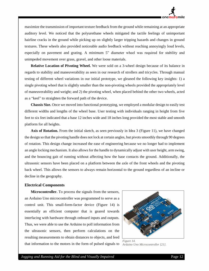
Microcontroller. To process the signals from the sensors,
an Arduino Uno microcontroller was programmed to serve as a
control unit. This small-form-factor device (Figure 14) is
essentially an efficient computer that is geared towards
interfacing with hardware through onboard inputs and outputs.
Thus, we were able to use the Arduino to poll information from
the ultrasonic sensors, then perform calculations on the
resulting measurements to obtain distances to objects, and feed
that information to the motors in the form of pulsed signals to Figure 14.
Arduino Uno Microcontroller [21].

Jogging and Running Aid for the Blind and Visually Impaired Page 13
one milemore
vary vibrational intensity depending on the distance of the detected object (with more intense pulses
indicating objects closer to the sensor). A diagram of the wiring schematic is available in Appendix D.
Power. Power to the device is currently provided by a standard 9V battery. Assuming usual drain
conditions, this device should run for approximately 8 hours on a single battery charge.
Ultrasonic Sensors. To detect objects in front of the
device, a pair of ultrasonic sensors were utilized. These sensors
function through echolocation: an emitter sends out a sub-sonic
pulse, which then hits an object, and subsequently returns to a
collector (the emitter and collector are the two cylindrical silver
objects seen in Figure 15). An internal clock on the Arduino
measures the time between the sending and receiving of the
pulse, and then divides by the speed of sound to obtain the total
travel distance of the pulse. Dividing this number in half
provides the distance, in inches, of an object detected by the
pulse. For optimal positioning, the sensor pairs were placed at six degrees off-center to allow for wide, yet
overlapping, fields of view. This number may be adjusted to suit future prototype needs. Calculations and
diagrams used for the sensors are available in Appendix E.
Vibrating Feedback. Haptic feedback is given to the user via a pair of
vibrating motors (Figure 16). When the Arduino sends the proper signal, these
motors will rotate and vibrate with intensity inversely proportional to the
distance of the object. Each motor is tied to a sensor, so that when the left sensor
detects an object, the left motor will vibrate, and vice versa. If an object is
detected across both sensors, then both motors will activate, indicating either a
large object ahead, or multiple objects.
Programming Component
Programming for the device was performed using the Arduino Interactive Development Environment
and open-source tools. The source code for the sensors and motors can be seen in the Appendix F under
“Arduino / Ultrasonic Sensor Code”.
Preliminary Testing
Each round of prototypes underwent user testing. Assuming the appropriate levels of functionality, the
main concerns for user testing were ease of use and comfort. Members of the design team both used and
observed the use of prototypes at various stages. As recommended by the project suggester, we fashioned
a pair of excluders by covering most of the surface of safety goggles with black electrical tape so that we
Figure 15.
Parallax PING)))™ Ultrasonic Sensor [21].
Figure 16.
Vibrating motor [21].

Jogging and Running Aid for the Blind and Visually Impaired Page 14
one milemore
could experience using the device with a 5-degree field of vision. The project suggester was also able to
test the device at various stages.
Since the initial and functional prototyping determined the optimal design for wheel type, wheel size,
device size, and degrees of freedom, user testing checked the height adjustability, ergonomics, and comfort
over prolonged use. The main cane shaft was a telescoping rod that could range from 60-112 cm, adequate
for user 5 ft to 6 ft in height. Since the shaft pivoted around the front wheels, users could employ a natural
arm swing while running without affecting device function.
The bicycle handle grip that interfaced with the shaft via ball-socket joints was a later addition and
greatly improved user comfort especially over jogs longer than .25 miles. The previous handle which was
just a grip on the end of the shaft caused wrist pain due to the awkward angle required to hold it. The new
ball-socket joints allowed for 360-degrees of freedom for the direction of the handle and the bicycle grip is
molded to fit comfortably in the palm. The bicycle grip is weighted to provide users with greater perceived
control of the device without being so heavy that the user gets tired from holding it up. And since much of
the device’s weight in concentrated near the ground and atop relatively large wheels, the user needs to issue
little effort to keep the device moving forward.
We did notice a shallow learning curve when our project suggester tried out our device. Since Brian
was used to correcting the navigation errors of his Ambutech rectangular mobility device, which warped
and listed sideways, when he applied the same corrections to our device, he found our device swerving as
well. As Brian began to put more faith in our device, spending less time looking down at the device and
letting the device guide him, we noticed his path straightened considerably.
Jogging and Running Aid for the Blind and Visually Impaired Page 15
one milemore
Current Prototype Results
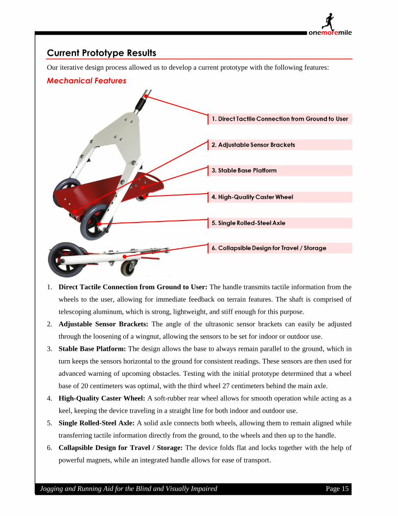
Our iterative design process allowed us to develop a current prototype with the following features:
Mechanical Features
1. Direct Tactile Connection from Ground to User: The handle transmits tactile information from the
wheels to the user, allowing for immediate feedback on terrain features. The shaft is comprised of
telescoping aluminum, which is strong, lightweight, and stiff enough for this purpose.
2. Adjustable Sensor Brackets: The angle of the ultrasonic sensor brackets can easily be adjusted
through the loosening of a wingnut, allowing the sensors to be set for indoor or outdoor use.
3. Stable Base Platform: The design allows the base to always remain parallel to the ground, which in
turn keeps the sensors horizontal to the ground for consistent readings. These sensors are then used for
advanced warning of upcoming obstacles. Testing with the initial prototype determined that a wheel
base of 20 centimeters was optimal, with the third wheel 27 centimeters behind the main axle.
4. High-Quality Caster Wheel: A soft-rubber rear wheel allows for smooth operation while acting as a
keel, keeping the device traveling in a straight line for both indoor and outdoor use.
5. Single Rolled-Steel Axle: A solid axle connects both wheels, allowing them to remain aligned while
transferring tactile information directly from the ground, to the wheels and then up to the handle.
6. Collapsible Design for Travel / Storage: The device folds flat and locks together with the help of
powerful magnets, while an integrated handle allows for ease of transport.
Jogging and Running Aid for the Blind and Visually Impaired Page 16
one milemore
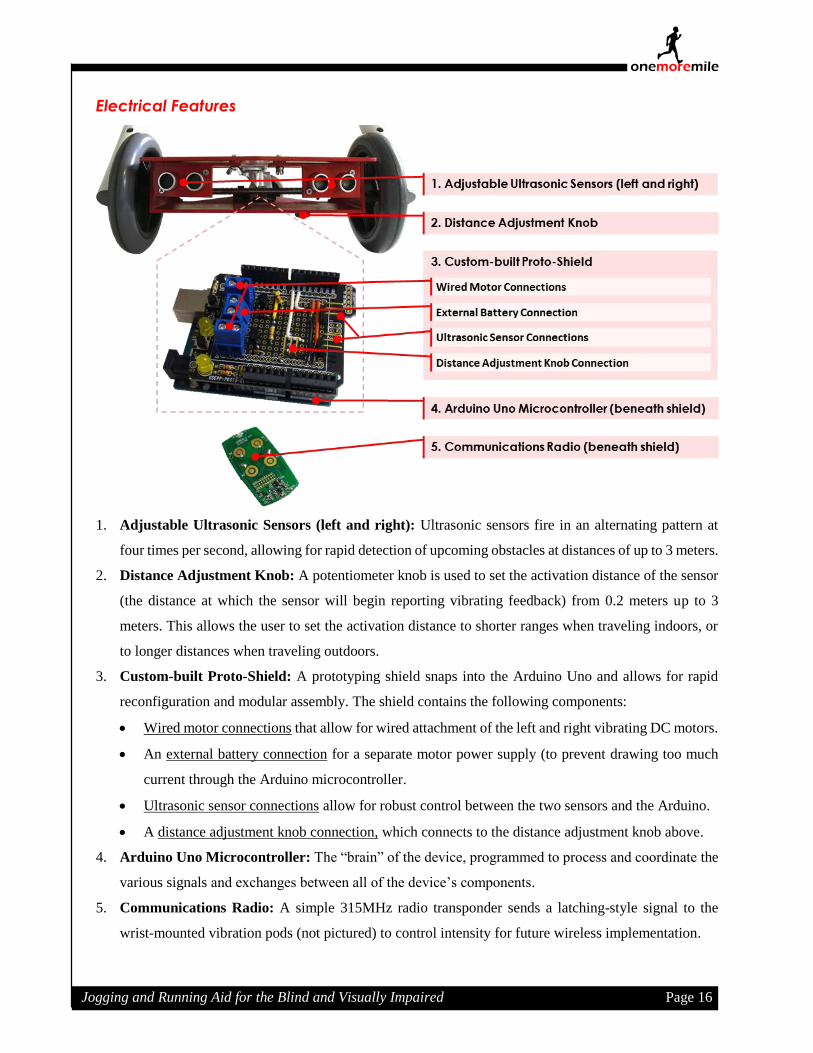
Electrical Features
1. Adjustable Ultrasonic Sensors (left and right): Ultrasonic sensors fire in an alternating pattern at
four times per second, allowing for rapid detection of upcoming obstacles at distances of up to 3 meters.
2. Distance Adjustment Knob: A potentiometer knob is used to set the activation distance of the sensor
(the distance at which the sensor will begin reporting vibrating feedback) from 0.2 meters up to 3
meters. This allows the user to set the activation distance to shorter ranges when traveling indoors, or
to longer distances when traveling outdoors.
3. Custom-built Proto-Shield: A prototyping shield snaps into the Arduino Uno and allows for rapid
reconfiguration and modular assembly. The shield contains the following components:
Wired motor connections that allow for wired attachment of the left and right vibrating DC motors.
An external battery connection for a separate motor power supply (to prevent drawing too much
current through the Arduino microcontroller.
Ultrasonic sensor connections allow for robust control between the two sensors and the Arduino.
A distance adjustment knob connection, which connects to the distance adjustment knob above.
4. Arduino Uno Microcontroller: The “brain” of the device, programmed to process and coordinate the
various signals and exchanges between all of the device’s components.
5. Communications Radio: A simple 315MHz radio transponder sends a latching-style signal to the
wrist-mounted vibration pods (not pictured) to control intensity for future wireless implementation.

Jogging and Running Aid for the Blind and Visually Impaired Page 17
one milemore
Ergonomic Features
1. Lightweight Fatigue-Free Handle: The vertical component of the device requires only 300 grams to
raise the handle, which prevents fatigue during extended periods of use.
2. Adjustable Telescopic Handle: The lightweight shaft is able to adjust and lock from 60 cm to 112 cm.
3. Removable Double-Ball Pivoting Joint: This joint allows for 3-axis adjustment, providing the handle
with unlimited lockable positions. In addition, the handle is threaded directly into the shaft, allowing it
to be removed or re-attached without the need of tools.
4. Soft Ergonomic Grip: A soft rubber grip eases fatigue during jogging and prevents cramping of the
hand during extended periods of use.
5. Large Horizontal Base Platform: The large base provides over 800 square centimeters of horizontal
space, which can be used for storage or additional sensor placement.
Aesthetic & Protective Features
Since the white cane (with or without a red tip) is a legally recognized device for granting right of way
[14] , we chose to color our prototype in a similar fashion. This allows pedestrians to acknowledge the
presence of a user who is visually impaired without embarrassing questions. In addition, several coats of
primer, pigment, and clear coat protect the device from the elements, allowing it to be wiped clean and
providing it with a more polished and professional appearance.

Jogging and Running Aid for the Blind and Visually Impaired Page 18
one milemore
Software & Electrical Component Optimization
The major reason for incorporating electrical capabilities is to provide advanced warning of obstacles.
The electrical components (ultrasonic sensors and wired vibrational feedback) did not undergo as much
revision as the mechanical components, however modifications were made to increase the energy efficiency
of the vibrating motors. Additionally, a knob / potentiometer was added to the base of the device to scale
the sensor sensitivity, providing longer range sensing for outdoors and shorter range sensing for indoors.
On the software side, code was optimized to run faster and allow for sensor scaling and to ensure the device
did not draw too much current from the Arduino at any one time (to prevent shorts and to optimize battery
life). The updated code can be seen in Appendix F. Feedback concerning the electrical components from a
variety of testers of different ages, body types and disabilities was unanimously positive.
Cost
As mentioned in the introduction, approximately 90% of the world’s visually-impaired population live
in low-income settings. As such, it was our goal to keep the price of the device as low as possible and
relatively simple to reproduce on a wider scale. Table 1 below indicates the components used to produce
the current prototype and their retail costs. Note that a finalized version would have a lower cost due to
scaling, better component sourcing, and optimized production methods.
Table 1: Current Prototype Costs
Item Source Quantity Per Unit Total Cost
Duron board (18 x 24 inches) Stanford PRL 1 $3.00 $3.00
OSEPP Ultrasonic Sensors Fry’s Electronics 2 $5.99 $11.98
Arduino Uno Microcontroller Fry’s Electronics 1 $19.99 $19.99
Arduino Prototyping Shield Fry’s Electronics 1 $10.99 $10.99
Miscellaneous Wiring Fry’s Electronics 1 $4.99 $4.99
Potentiometer & Knob Fry’s Electronics 1 $2.99 $2.99
5V Power Supply Fry’s Electronics 1 $6.99 $6.99
Schwinn Comfort Grip Amazon.com 1 $9.99 $9.99
Double-Socket Arm Amazon.com 1 $7.99 $7.99
5” Walker Wheels Walgreen’s 1 $10.85 $10.85
3” Caster Wheel Home Depot 1 $2.85 $2.85
Miscellaneous Mounting Hardware Home Depot 1 $7.00 $7.00
Total Cost $99.61
Safety
Currently, the only safety concerns with the device are due to its prototype status. Particularly, a further
prototype would implement a waterproof enclosing to protect the circuitry and electrical components.
Jogging and Running Aid for the Blind and Visually Impaired Page 19
one milemore
Despite this, the current prototype operates at low voltages and currents, so there is no risk of shock or
danger to the user.
Reliability and Safety
While the addition of electronic components may seem to limit the usage time of the device, they are
actually capable of running for over ten hours on a single charge. In addition, the device can be charged
with a standard Micro-USB adapter, similar to those used in charging cell phones and other consumer
electronics.
As for safety considerations, mechanically, this device does not pose a greater risk than a white cane.
Electrically, the voltage (5V) and current (<100 mA) are low enough that shorts due to rain or wear-and-
tear on wires, while damaging to components, are not harmful to the user.
Discussion
Challenges & Potential Solutions
Most the of the challenges/future work lies in the electronic half of this prototype; for the most part, the
last prototype made could mechanically be a conceivably marketable device. The only major area where
change might be necessary would be in the collapsibility of the cane. While we like the sturdiness of the
handle and the fact that it can be collapsed at all, it is still too large to comfortably fit in tote bag or
something similar without sticking out. Therefore, a second way of folding the rest of the cane down so
that it is no longer than the length of the base when fully collapsed is something to consider.
As mentioned previously, the electrical components provided a few challenges. While many canes with
sensors exist on the market, many use more specialized (and therefore expensive) components than would
fit within our budget. We had to develop a system that would provide the user with adequate information
about his surroundings, but do so using commonly available electronic components. We also had to design
the system to prevent false positives that could occur from too many ultrasonic sensors, but still differentiate
between the location of different objects successfully. In addition, we required the sensors to stay relatively
parallel to the ground, which necessitated a swiveling component of the physical structure.
Another major challenge was relaying the information from the sensors back to the user. We want to
be able to differentiate between a singular central object detected by the two sensors or two peripheral
objects detected by the two sensors (so, for example, having a left-right system that both went off with an
object in the middle wouldn’t work, since it could indicate either an object to the center or some
combination of multiple objects). Currently, the code attempts to solve this problem by activating both
vibrating motors in tandem when a singular central object is detected, or alternatingly pulsing the vibrating
motors when two different peripheral obstacles are detected. Testing on these feedback schemes is ongoing.

Jogging and Running Aid for the Blind and Visually Impaired Page 20
one milemore
Next Steps
We are very pleased with the final prototype that we developed for this quarter-long project. While the
device met all of the goals that we had set for ourselves, there are still aspects of the device that can be
improved. First, we need to create a more reliable wireless system, as the system in its current form is prone
to signal lag issues. Second, we need to find a better power supply, as the one we currently use is faulty and
failed after a few minutes of use. Third, a shell for the bottom of the device would be necessary, both to act
as a skid plate and to house the electronics properly. Lastly, we want to consider other potential markets
for the device, such as for children learning to navigate with a cane. With the addition of things like fun
noises, lighting effects, or modification to the vibration relay, the device could be a more enjoyable method
of learning to use assistive technologies for children.

Jogging and Running Aid for the Blind and Visually Impaired Page 21
one milemore
Acknowledgements
Team One More Mile would like to gratefully acknowledge assistance and encouragement from of the
following individuals and groups, without whom this project would not have been possible:
Our instructor, Professor Dave Jaffe, and his Engineering 110 / 210 course, Perspectives in Assistive
Technology.
Brian Higgins, Blind Rehabilitation Specialist at the Palo Alto Veteran’s Administration and suggester
of this project.
The teaching assistants at the Stanford Product Realization Lab and Room 36.
Our fellow students and community guests.
Project suggester Brian Higgins with the functional prototype.
Jogging and Running Aid for the Blind and Visually Impaired Page 22
one milemore
References
[1] T. Bickford, "Care and Feeding of the Long White Cane: Instructions in Cane Travel for Blind
People," Future Reflections: The National Federation of the Blind Magazine for Parents and
Teachers of Blind Children, pp. 13-32, Winter 1996.
[2] American Academy of Orthopedic Surgeons, "How to Use Crutches, Canes, and Walkers,"
February 2015. [Online]. Available: http://orthoinfo.aaos.org/topic.cfm?topic=A00181.
[Accessed 13 March 2016].
[3] World Health Organization, "Visual Impairment and Blindness," August 2014. [Online]. [Accessed
3 March 2016].
[4] Achilles International, "Overview: Achilles International," [Online]. Available:
http://www.achillesinternational.org/programs/overview. [Accessed 2 March 2016].
[5] E. O. F. M. P. A. Ann Hallemans, "Low Vision Affects Dynamic Stability of Gait," Gait &
Posture, vol. 32, no. 4, p. 547–551, 2010.
[6] VisionAware: American Foundation for the Blind, "What Type of Cane Should I Use?," 2015.
[Online]. Available: http://www.visionaware.org/info/everyday-living/essential-skills/an-
introduction-to-orientation-and-mobility-skills/what-type-of-cane-should-i-use/1235. [Accessed
12 March 2016].
[7] American Council of the Blind, "White Cane Laws for States," 24 October 2013. [Online].
Available: http://www.acb.org/whitecane. [Accessed 6 February 2016].
[8] Ambutech, "Rectangular AMD," Unknown. [Online]. Available: https://ambutech.com/shop-
online/rectangular-amd. [Accessed 16 February 2016].
[9] IITDelhi, "SmartCane," Unknown. [Online]. Available: http://assistech.iitd.ernet.in/smartcane.php.
[Accessed 16 February 2016].
[10] Sound Foresight Technology, Unknown. [Online]. Available: https://www.ultracane.com/.
[Accessed 16 February 2016].
[11] T. Lewis, "Seeing-Eye Vest? Vibrating Clothing Helps Blind Navigate," 14 November 2014.
[Online]. Available: http://www.livescience.com/48760-vibrating-vest-blind-navigation.html.
[Accessed 16 February 2016].
[12] DesignBuzz, "GPS Navigation Devices to Guide the Visually Impaired," 14 April 2012. [Online].
Available: http://www.designbuzz.com/10-gps-navigation-devices-guide-visually-impaired/.
[Accessed 16 February 2016].

Jogging and Running Aid for the Blind and Visually Impaired Page 23
one milemore
[13] J. D'Onfro, "How Google Glass Helped This Blind 13-Year-Old Dancer Get His Vision Back," 24
November 2014. [Online]. [Accessed 3 March 2016].
[14] American Council of the Blind, "White Cane Laws for States," 24 October 2013. [Online].
[Accessed 8 March 2016].
[15] M.-L. Nguyen, "Blind/visually impaired runner and his guide at the 2014 Paris Marathon," 6 April
2004. [Online]. Available:
https://commons.wikimedia.org/wiki/File:2014_Paris_Marathon_t083553.jpg. [Accessed 16
February 2016].
[16] "Bundu Basher," [Online]. Available: http://www.sauerburger.org/dona/bundu. [Accessed 14
March 2016].
[17] Western Blind Rehabilitation Center, "WBRC Team Completes the 100th Annual Bay to Breakers
Race," 17 May 2011. [Online]. Available: http://westernblind.blogspot.com/2011/05/wbrc-
team-complete-100th-annual-bay-to.html. [Accessed 13 March 2016].
[18] Health Mark, Inc., "Alumilite Silver Walking Cane," 2015. [Online]. Available:
http://www.healthmarkinc.net/product/alumilite-walking-cane/. [Accessed 13 March 2016].
[19] K. Barry, "Wired," 2 February 2009. [Online]. Available:
http://www.wired.com/2009/02/lightlanes-lase. [Accessed 2 February 2016].
[20] "RobotShop Online Store," 2016. [Online]. Available:
http://www.robotshop.com/en/corporate/about. [Accessed 2 February 2016].
Jogging and Running Aid for the Blind and Visually Impaired Page 24
one milemore
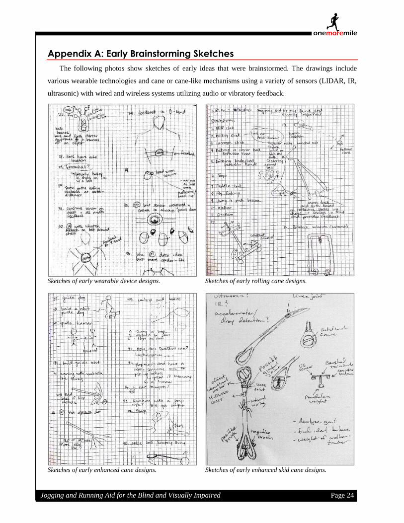
Appendix A: Early Brainstorming Sketches
The following photos show sketches of early ideas that were brainstormed. The drawings include
various wearable technologies and cane or cane-like mechanisms using a variety of sensors (LIDAR, IR,
ultrasonic) with wired and wireless systems utilizing audio or vibratory feedback.
Sketches of early wearable device designs. Sketches of early rolling cane designs.
Sketches of early enhanced cane designs. Sketches of early enhanced skid cane designs.

Jogging and Running Aid for the Blind and Visually Impaired Page 25
one milemore
Appendix B: Additional Photographs of Initial Prototype
The following two pictures show early prototypes using 2-inch pink foam, repurposed purchased items
and school supplies. These prototypes allowed us to test the stability and proportions of the base as well as
a number of pivoting axes.
Initial prototype in a horizontal configuration.
Initial prototype in a vertical configuration.

Jogging and Running Aid for the Blind and Visually Impaired Page 26
one milemore
Appendix C: Additional Photographs of Functional Prototype
These photos show different views of the functional prototype made of laser cut 1/8” Duron and
repurposed items (handles, wheels, etc.). This prototype possessed functional mechanical and electrical
components that allowed for intensive testing. Further improvements to this prototype were mainly
aesthetic or to improve ergonomics and transportability.
Complete view of functional prototype.
Front view of functional prototype with sensors.
Side view of functional prototype with main axle.

Jogging and Running Aid for the Blind and Visually Impaired Page 27
one milemore
Appendix D: Electronics Wiring Diagram
The following diagram illustrates the connections within the device. A separate power supply was
required for the wired version to provide two different voltages, but a further prototype would fully
incorporate the wireless capabilities discussed previously.
Appendix E: Sensor Calculations
In order to convert the sensor readings into useful measurements, the following equation was used:
𝑃𝑢𝑙𝑠𝑒 𝑇𝑟𝑎𝑣𝑒𝑙 𝑇𝑖𝑚𝑒
𝑆𝑝𝑒𝑒𝑑 𝑜𝑓 𝑆𝑜𝑢𝑛𝑑 ×
𝑇𝑜𝑡𝑎𝑙 𝐷𝑖𝑠𝑡𝑎𝑛𝑐𝑒
2→
(𝑡
340.29 m/s)
2= 𝐷𝑖𝑠𝑡𝑎𝑛𝑐𝑒 (𝑖𝑛 𝑐𝑒𝑛𝑡𝑖𝑚𝑒𝑡𝑒𝑟𝑠)
In addition, the diagram at right was used to
determine optimal sensor placement based on both
manufacturer values and measured values. These
allowed us to determine that at the maximum range
of 3 meters, an offset of six degrees would create
three detection zones: left, center (due to
overlapping detection fields), and right.

Jogging and Running Aid for the Blind and Visually Impaired Page 28
one milemore
Appendix F: Code for Object Detection and Vibration Feedback
/* Written by Thomas Trzpit for ENGR 110 (Winter 2015-2016)
*
* Pin Assignments / Wiring
* Component Part Arduino
* Sensor Left SIGNAL Pin 6
* 5V 5V
* GND GND
* Sensor Right SIGNAL Pin 7
* 5V 5V
* GND GND
* Motor Left 3V Pin 10
* GND GND
* Motor Right 3V Pin 9
* GND GND
* Potentiometer 5V 5V
* GND GND
* Sweeper Analog Pin 0
*/
/*
* Pin Constant Declarations
*/
const int pingLeft = 6 ;
const int pingRight = 7 ;
const int leftMotor = 10 ;
const int rightMotor = 9 ;
const int rangePin = 0 ;
const int maxSpeed = 255 ;
/*
* Global Variable Declaration
*/
Int rangeValue ,
leftSpeed ,
rightSpeed ,
delaySpeed = 200 ;
long durationLeft ,
durationRight ,
inchesLeft ,
inchesRight ;
/*
* Program Initialization
*/
void setup () {
// Pin mode settings
pinMode ( leftMotor , OUTPUT ) ;
pinMode ( rightMotor , OUTPUT ) ;
}

Jogging and Running Aid for the Blind and Visually Impaired Page 29
one milemore
/*
* Main program loop
*/
void loop () {
// Disable current draw for motors
analogWrite ( leftMotor , 0 ) ;
analogWrite ( rightMotor , 0 ) ;
// Pull potentiometer value to set range sensitivity
getRangeValue () ;
// Pull sensor readings
delay ( delaySpeed / 2 ) ;
pingLeft () ;
delay( delaySpeed / 2);
pingRight () ;
// Convert reading to inches
inchesLeft = microsecondsToInches(durationLeft);
inchesRight = microsecondsToInches(durationRight);
// Conditional statement to activate vibrational motor
if ( inchesLeft <= rangeValue ) {
leftSpeed = map ( inchesLeft , 0 , rangeValue , maxSpeed, 0 ) ;
analogWrite(leftMotor, leftSpeed); // set the new speed
delay(delaySpeed );
} else {
analogWrite(leftMotor, 0); // set the new speed
}
analogWrite(leftMotor, 0); // set the new speed
if ( inchesRight <= rangeValue ) {
rightSpeed = map ( inchesRight, 0 , rangeValue, maxSpeed, 0 ) ;
analogWrite(rightMotor, rightSpeed); // set the new speed
delay(delaySpeed );
} else {
analogWrite(rightMotor, 0); // set the new speed
}
analogWrite(rightMotor, 0); // set the new speed
}

Jogging and Running Aid for the Blind and Visually Impaired Page 30
one milemore
/*
* Helper Functions
*/
// Fire left ultrasonic sensor
void pingLeft () {
pinMode(pingLeft, OUTPUT);
digitalWrite(pingLeft, LOW);
delayMicroseconds(2);
digitalWrite(pingLeft, HIGH);
delayMicroseconds(5);
digitalWrite(pingLeft, LOW);
pinMode(pingLeft, INPUT);
durationLeft = pulseIn(pingLeft, HIGH);
pinMode(pingLeft, INPUT);
}
// Fire right ultrasonic sensor
void pingRight () {
pinMode(pingRight, OUTPUT);
digitalWrite(pingRight, LOW);
delayMicroseconds(2);
digitalWrite(pingRight, HIGH);
delayMicroseconds(5);
digitalWrite(pingRight, LOW);
pinMode(pingRight, INPUT);
durationRight = pulseIn(pingRight, HIGH);
pinMode(pingRight, INPUT);
}
// Convert sensor reading to inches
long microsecondsToInches ( long microseconds ) {
return microseconds / 74 / 2;
}
// Convert sensor reading to centimeters
long microsecondsToCentimeters ( long microseconds ) {
return microseconds / 29 / 2;
}
// Pull range sensitivity settings
void getRangeValue() {
rangeValue = analogRead ( rangePin ) ;
rangeValue = map ( rangeValue , 0 , 1024, 20, 108 ) ;
}