Embed Size (px)
Citation preview
The Cowichan Bay Improvement District and Cowichan Bay Volunteer Fire Rescue
Request for Proposal # CBID-18-42
One (1) New Water Tender Fire Apparatus on a Supplied Chassis
Sealed Proposals will be received in the office of:
Cowichan Bay Improvement DistrictP.O. Box 1039Duncan, B.C.
V9L 3Y2Attention: Administrator
Up to 7:00 p.m. P.S.T., Tuesday, September 18th, 2018
Amended to 7:00 p.m. P.S.T., Tuesday, October 2nd, 2018(Document updated Effective August 24th, 2018)

Cowichan Bay Improvement District
REQUEST FOR PROPOSALS (RFP)
One (1) New Water Tender Fire Apparatus on a Supplied Chassis
On behalf of Cowichan Bay Volunteer Fire Rescue, the Cowichan Bay Improvement District (the “District”) is interested in receiving Proposals for a New Water Tender Fire Apparatus on a Supplied Chassis (the “Apparatus”).
The District is not necessarily interested in obtaining the lowest price for this product.
The District is interested in presentations from all suppliers who have proven experience and qualifications for the design, construction and supply of the Apparatus which will be on a Kenworth T-800 chassis.
The quality of the product, performance, delivery, maintenance, service and other factors will be taken into consideration in the evaluation of this RFP.
This is a Request for Proposals only and will not necessarily give rise to a contract.
Proposals received after the closing time will be returned unopened.
The District will endeavour to keep all Proposals confidential.
Technical or commercial information included in the District contract document shall not be released if the Administrator of the District deems such releases inappropriate, subject to the Freedom of Information and Protection of Privacy Act.
The District reserves the right to accept the Proposal deemed to serve the best interests of the District and to be most beneficial to the District.
Further information may be obtained from the District by contacting the District’s Administration Assistant, Dave Ferguson, at either (250) 710-0618 or via email at [email protected]
Karen CowardAdministratorCowichan Bay Improvement District
2
Table of Contents
Page
1.0 General Requirements……………………………………………………. 5
1.1 Intent Statement…………………………………………………… 51.2 Bid Submission Requirements…………………………………… 51.3 Performance Requirements……………………………………… 61.4 Delivery and Payment Terms…………………………………….. 61.5 Approved Drawings……………………………………………….. 71.6 Proponent’s Experience and Reliability………………………… 71.7 Insurance…………………………………………………………… 71.8 Pre-Construction and Inspection Meetings…………………….. 71.9 Maintenance and Service………………………………………… 81.10 Special Requirements……………………………………………. 81.11 Training…………………………………………………………….. 81.12 Warranty Requirements………………………………………….. 91.13 Sub-Contractors…………………………………………………… 91.14 Optional Equipment……………………………………………….. 91.15 Enquiries…………………………………………………………… 10
2.0 Apparatus Minimum Specifications………..………………………… 11
2.1 Scope…………………...………………………………………….. 112.2 Engine………………..……………………………………………. 122.3 Transmission……………………..………………………………... 122.4 Fuel Tank……………..……………………………………………. 122.5 Cab and Chassis……….…………………………………………. 122.6 12 Volt DC Electrical System…………………………………….. 132.7 Portable Tanks……………………...…...………………………… 152.8 Body Construction Detail…………………………………………. 152.9 Pump and Plumbing………………...……………………………. 162.10 Frame Specification………………………………………………. 182.11 Steering……………………………………………………………. 192.12 Axles/Suspension…………………………………………………. 192.13 Rims/Tires…………………………………………………………. 192.14 Braking System……………………………………………………. 192.15 Paint………………………………………………………………… 202.16 Technical Data……………………………………………………. 20
3

3.0 Bid Evaluation……………………………………………………………… 21
3.1 Proposal Bid Sheet……………………………………………….. 213.2 Selection Criteria………………………………………………….. 22
3.2.1 Price……………………………………………………… 223.2.2 Proponent qualifications and experience……………. 223.2.3 Training, Warranty, Service and Repair ……………… 223.2.4 Proposal Quality and Clarity…………………………… 22
4.0 Attachments………………………………………………………………... 23
4.1 Attachment “A”- Paint scheme, Rear Dump System, Layout… 234.2 Attachment “B” - Documentation, including manuals………… 234.3 Attachment “C” – Photographs ………………...……………… 244.4 Attachment “D” – Optional Equipment…………………………... 24
4

1.0 General Requirements
1.1 Intent Statement
As stated in the preamble, the Cowichan Bay Improvement District is interested in receiving Requests for Proposal from qualified contractors (the “Proponent”) for the supply of a New Water Tender Fire Apparatus. (the “apparatus”)
This Apparatus must be designed and engineered specifically for fire service application. The apparatus will replace an existing unit, a 2004 Sterling c/w a 2200-gallon tank, which will be disposed of separately and is not part of this RFP process. The new apparatus shall to be of a height, width and length, as specified in the RFP, to accommodate the existing fire hall. The apparatus shall meet all requirements of NFPA 1901 Standard for Automotive fire Apparatus (2009 Edition) for “Pumper Fire Apparatus” unless otherwise stated in this document.The apparatus shall meet all requirements of CAN/ULC S515-04 Automobile Firefighting Apparatus.The apparatus must also meet all other applicable Canadian, Provincial vehicle safety regulations in addition to NFPA standards as specified in the RFP.
The Proponent is encouraged to use innovation when developing its Proposal and to propose revisions or alternatives to the specifications outlined in this document, that would be considered beneficial to Cowichan Bay Volunteer Fire Rescue. (“CBVFR”)
1.2 Bid Submission Requirements
A maximum of (2) physical copies of each Proposal, along with the detailed specification/bid form included as part of this package, shall be submitted in a sealed envelope and shall be addressed to:
Cowichan Bay Improvement District P.O. Box 1039Duncan, B.C.V9L 3Y2Attention: Administrator
The Proposal envelope must be clearly marked “New Water Tender Fire Apparatus”. Submitted Proposals transmitted by facsimile machine or email will not be considered.
Proposals must be received no later than 7:00 pm P.S.T., Tuesday, September 18th, 2018. Proposals will not be opened in public. It is incumbent upon the Proponent to ensure their submission has been received by the District prior to the closing date and time. All proposals shall become the property of the District. Proposals received after the noted due date and time will not be considered and will be returned unopened to the Proponent.
5

Your proposal should clearly show your complete company name, nearest representative to Cowichan Bay, and the name and contact information for the primary contact person.
Inland Kenworth Nanaimo shall provide a brochure of the chassis on which the tender is based.
Proponents are solely responsible for any costs or expenses related to the preparation and submission of proposals.
1.3 Performance Requirements
The apparatus shall be designed to operate safely and efficiently at the gross vehicle weight rating (“GVWR”) specified by the Original Equipment Manufacturer (“OEM”), under all operating conditions and in line with current industry standards.
The Apparatus will be used primarily as a support vehicle providing a water supply to the Cowichan Bay Volunteer Fire Rescue fire suppression apparatus.
The apparatus will be responding on rural roads, the Trans-Canada Highway, within sub-divisions and to waterfront locations. The apparatus will be operating at grades up to 12%.
The apparatus shall meet the standards of the Canada Motor Vehicle Safety Act and the Regulations made thereunder, in effect on the date of manufacture of the apparatus
The Standard Design of the apparatus shall conform to all applicable laws, regulations and industry standards governing manufacture, safety, noise levels and pollution in effect in Canada at the time of manufacture. The sound level in the cab when measured in accordance with SAE International Standard J336 - Sound Level for Truck Cab Interior which should not exceed 85-dB.
The expected service life of the apparatus is to be 20 years
1.4 Delivery and Payment Terms
Acceptance of the apparatus shall be at the Cowichan Bay Volunteer Fire Rescue Firehall, located at 4461 Trans-Canada Highway, Cowichan Bay, BC Canada.
All invoices resulting from this proposal will be paid on a Net 30 day basis as per the District’s standard payment terms.
Proponents are to provide pricing in Canadian funds and their payment schedule expectations. The apparatus is to be shipped FOB destination, including all delivery charges. The Proponent shall bear all risks of loss and/or damage until delivery is completed.
The Proponent shall indicate a delivery date between December 1, 2018 and May 31, 2019 as part of the proposal.
6

The Fire Chief and Administrator, or their representatives, will make final acceptance after witness to satisfactory operation of the Apparatus as supplied per attached specifications.
All deficiencies must be addressed and corrected to the satisfaction of the District before final acceptance is made. Final payment will not be made until deficiencies are addressed.
1.5 Approved Drawings
A concept drawing of the exact apparatus being proposed must be furnished with the bid. Drawings must include the top, left, right, rear and front sides with the chassis cab. These drawings must include details of all compartment sizes, openings, layout, lights, sirens, suctions, discharges and pump configuration.
All drawings will be supplied in both print and in a digital form
All drawings will be signed off by a company representative and form part of the proposal.
1.6 Proponent’s Experience and Reliability
The Proponent shall furnish satisfactory evidence that they have the ability to design and construct the apparatus specified and shall state in the bid proposal the location of the factory where the apparatus is to be built, and where future service work will be performed. Such information should include details of the welding certification held by the Proponent and those employed to carry out this critical work on this project.
The Proponent shall provide a corporate profile. The profile should include details of their size, services provided, areas of expertise and history of the company. A minimum of three (3) references of organizations currently using similar apparatus, delivered by the Proponent over the past 5 years, must be provided. If there are special concerns or restrictions on our use of the reference, these concerns must be addressed in the Proposal. We will not complete any agreement without adequate reference checks. Please include organization name and address, telephone numbers, e-mail addresses and the name of the primary contact for each of the references.
1.7 Insurance
The Proponent will be responsible for the safe keeping and storage of the vehicle during construction and will be liable and responsible for any damage to this vehicle which will be purchased from Inland Kenworth, Nanaimo BC in the name of the Cowichan Bay Improvement District.
1.8 Pre-Construction and Inspection Meetings
The Proponent shall include consideration for two meetings in their proposal.
A pre-construction meeting
7

A final prior-to-delivery inspection meeting.
The final prior-to-delivery inspection meeting shall take place in person at the Proponent`s facility. All costs incurred in holding these meetings shall be included as part of the proposal. The Proponent to provide details of what costs the Proponent will pay for regarding these meetings to allow two representatives of the District to attend.
The pre-construction meeting shall be an opportunity to review and approve all final designs and equipment mounting locations, prior to any construction. A factory representative shall be present during the pre-construction meeting to answer any questions relating to the apparatus design.The inspection final prior-to-delivery inspection meeting shall be held to allow for detailed inspection of the apparatus. Testing records and certificates shall be available at the final prior-to-delivery inspection meeting.
The District reserves the right to inspect the apparatus at any other time during construction at the expense of the District
1.9 Maintenance and Service
The proposal should address the issues of:
Is technical support readily available during regular business hours? The location of the Proponent’s dedicated service facilities. Details of whether the after-sales service provider is owned or contracted
by the Proponent. Details of response times and costs relating to service calls initiated by
the District.
1.10 Special Requirements
The apparatus must meet the following dimensions:
The Overall Height is to be no higher than 3.0 m or 9’ 10” The Overall Width is to be no wider than 2.59 m or 8’ 6” The Overall Length, subject to be a maximum of 8.66 m or 28’ 5”
This importance of these special requirements is to ensure the Apparatus can be accommodated in the existing fire hall. The Proponent is requested to state the actual total loaded weight of the apparatus in their proposal.
1.11 Training
The Proponent to provide complete details of all operator training they will provide in their proposal.
The expectation of the District is that upon delivery of the apparatus, fire department CBVFR personnel shall be properly instructed as to the proper use of the apparatus. This training shall include the use of the Fire pump and any unique mechanical components
8
A factory-trained representative shall complete all training. All training will be performed at the Cowichan Bay firehall for a period of two days with all costs of the training forming part of this proposal.
1.12 Warranty Requirements
Each piece of new fire apparatus shall be warranted to be free from defects in materials or workmanship under normal use and service.
The Proponent shall supply, as a part of their bid package, a copy of the warranty or warranties that they propose to provide. The successful Proponent will be responsible for processing all the required paperwork with the manufacturer to supply parts and warranty labour payments.
The District will arrange a preferred full 100 per cent “bumper to bumper” warranty for a two-year period, with the chassis supplier. The Body Structure Warranty shall be in effect for a 10-year period.
The warranty issues to be addressed by the Proponent shall include, but not be limited to, a single/sole source warranty for the body’ sub-systems and components, a paint warranty, frame warranty, pump and plumbing warranty.
A minimum of 1 copy of all applicable manuals shall be provided in an electronic or digital format for parts not provided by the chassis provider. A sample shall be provided as a part of the proposal.
All warranty work is to be conducted in Cowichan Bay. The warranty coverage is to include all mechanics expenses. If this warranty coverage cannot be provided, detail the warranty options and associated costs to the District in the proposal.
The Warranty coverage, provided by the Proponent, shall commence upon the in-service acceptance of the apparatus by the District.
1.13 Sub-Contractors
Use of a subcontractor by the Proponent is acceptable as long as full details of the proposed sub-contractor are clearly outlined in the Proposal.The District will not permit any portion of this project to be given to a sub-contractor without the District`s prior written approval.
1.14 Optional Equipment
A list of accessory equipment is attached as Attachment “D”. These items are a consideration for placing into service on the new apparatus. The Proponent is invited to quote prices for the purchase of these items as a separate submission to the RFP.
9

1.15 Enquiries
All enquiries or clarifications with respect to this RFP must be directed, in writing, to the following people.
Financial - Karen CowardE-mail: [email protected]
RFP Document - Dave FergusonE-mail: [email protected]
Technical - Colin GawE-mail: [email protected]
Any revisions or clarifications to this RFP will be issued by the District in writing. All questions should be submitted via email, at least ten (10) working days prior to the closing time and date.
Information obtained from any other source is not official and should not be relied upon. Enquiries and responses will be recorded and may be distributed to all Proponents at the District’s option.
10

2.0 APPARATUS MINIMUM SPECIFICATIONS
Note: If the apparatus is non-compliant, as to any of the following specifications, details must be provided stating what shall be supplied and the reason for the substitution. The column provided on the right hand side of this Section is for Proponents to make notations in this regard
11

2.1 SCOPE
2.1.1 All items in this Purchase Description and Specification are commercially available. The fact that a manufacturer chooses not to provide a required item does not make this specification proprietary in nature.
2.1.2 The intent of this Purchase Description and Specification is to cover the minimum requirements that shall apply to the construction and performance of the proposed apparatus. The apparatus, when delivered by the Manufacturer, shall have met the latest NFPA 1901, 2009 edition standards and shall be ULC tested and labelled.
2.1.3 A copy of the apparatus stability certification shall be provided at the pre-delivery inspection.
2.1.4 The cab and chassis shall be a current model Kenworth T-800 chassis and will be provided by Inland Kenworth, Nanaimo BC
2.1.5 Mandatory requirements are identified by the word shall. Deviations will not be permitted.
2.1.6 Requirements identified by “should” shall be satisfied, however, the Cowichan Bay Volunteer Fire Rescue will consider alternative means for acceptance.
2.1.7 The manufacturer shall provide loose equipment only when specified within thisPurchase Description and Specification. Quotes for loose equipment listed inAttachment “D” to this document are invited as a separate process.
2.1.8 In the document “provided” shall mean “provided and installed”.
2.1.9 When a specific brand name is specified, the intent of the specification detail is to set parameters of form, fit, function or performance. It is the Proponent’s sole responsibility to provide the required, or requested, documentation, to substantiate an equivalency to the specified requirement. Failure by the Proponent to meet the conditions of this requirement will render the bid submission as non-compliant.
2.1.10 Where equipment certification to a standard (SAE or other) is required, the Proponent shall provide the certification upon request.
2.1.11 A nil response to a technical information question may be considered non-compliant.Any deviation from the Purchase Description and Specification shall be listed andexplained in the Certificate of Conformance.
2.1.12 The Certificate of Conformance takes precedence over all other technical data submittedby a Manufacturer. Should a Manufacturer intend to offer an alternate apparatus system,sub-system, and component, item of product other than that specified within this Purchasedescription and Specification, it shall be the Manufacturers responsibility to specificallydetail the alternative being offered on the Certificate of Conformance. Should no alternateapparatus systems, sub-systems, components, items or products be identified within theCertificate of Conformance, the Manufacturer shall provide an apparatus that fully meetsthe requirements of the Purchase Description and Specification in its entirety withoutexception.
2.1.13 Should a Proponent identify a specification error, omission, or inconsistency, the item should be identified and brought to the Cowichan Bay Volunteer Fire Rescue (“CBVFR”) Representative’s attention.
2.2 ENGINE
2.2.1 The engine shall be a Cummins 12.0L Diesel product.
2.2.2 The Engine shall have a minimum of 450 HP, reflect the Fire service application and be
12

filled with synthetic oil.
2.2.3 The fire apparatus shall be capable of attaining a speed of 35 m.p.h. (55 km/hr.) from astanding start within 25 seconds. (NFPA 1901 - 4.17.6.1).
2.2.4 Engine to have a thermostatically controlled fan.
2.2.5 Coolant filter required.
2.2.6 The coolant system should be of a capacity so that the engine does not overheat atany time.
2.2.7 Fuel primer required. Not to operate when there is a loss of engine oil pressure.Details to be provided with bid
2.2.8 Primary and Secondary fuel filters required with a means of draining water from theprimary fuel separator. There should also be an indicator light mounted in the dashthat alerts the driver of high water conditions in the fuel separator.
2.2.9 Engine brake required.
2.3 TRANSMISSION
2.3.1 The Transmission shall be an automatic sufficient to meet the load of the apparatus such as an Allison GEN IV-E 4000 EVS
2.3.2 A Transmission temperature gauge with warning light and buzzer shall be installedon the cab instrument panel & pump panel.
2.3.3 The gearshift indicator shall be backlit.
2.4 FUEL TANK
2.4.1 Fuel tank capacity must be at least 50 imperial gallons. The tank mounting details tobe provided and agreed upon with CBVFR representative at the pre-construction meeting.
2.4.2 The Fuel Tank shall have a 2” filler line with air bleed. No blowback to be allowed.
2.5 CAB & CHASSIS
2.5.1 The Cab shall be a two (2) door design.
2.5.2 Cab locks may be either keyed or electric.
2.5.3 The Driver’s seat and the Officer’s seat are to be 6-way electric seats.
2.5.4 Cab interior floor coating shall comply with NFPA 1901 15.7.4.2
2.5.5 Fused power feed cables to be provided for battery and ignition power.
2.5.6 Rear view mirrors to be heated, adjustable and to be accessible from the driver’slocation, as per NFPA 1901 14.3.5.
2.5.7 Heater/AC to have sufficient output defogger to insure windshield clearing.
2.5.8 All equipment to be secured as per NFPA 1901 14.1.11 and 14.1.11.1.
2.5.9 Seat belts shall conform to Federal Motor Vehicle Safety Standards(FMVSS No. 209 “Seat Belt assembles” as per NFPA 1901 14.1.3.1.)
2.5.10 Seat belt webbing shall be Orange or Red as per NFPA 1901 14.1.3.4.
13

2.5.11 Cab installation that meets or exceeds the WorkSafeBC requirements for allowableworkplace noise levels to be installed.
2.5.12 The front windows to be electrically controlled, controls to be within easy reach of the driver.
2.5.13 All seating positions to be WorkSafeBC compliant and provided with Whiplash protection.
2.5.14 Sun visors to be installed on both sides in front of the Driver’s and the Officer’s seats.
2.5.15 Door protection – lower scuff plates.
2.6 12 Volt DC ELECTRICAL SYSTEM
2.6.1 GENERAL SPECIFICATIONS
2.6.1.1 The Alternator shall be a minimum Leece Neville 270 amp. product.
2.6.1.2 Where a through-frame bulkhead connector is necessary, the connection should beprovided with protective loom, grommets, or other appropriate wrapping at each pointthat a connection passes through a panel or structural member.
2.6.1.3 Electrical circuits shall be protected by utilizing fuses, circuit breakers, fusible linksor solid-state equivalent devices.
2.6.1.4 The chassis system should have a centrally located electrical distribution area andhave all electrical components located in a manner that does not interfere with,or disrupt, apparatus operations. An access cover should be provided for access to theelectrical distribution area.
2.6.1.5 Automatic reset circuit breakers should be provided for directional lights, driving lightsand the emergency lighting systems.
2.6.1.6 Fused power connections should be provided for radio(s), chargers and sireninstallations at the electrical distribution area. Radio suppression shall be installedto allow radio equipment operation without interference
2.6.2 BODY WIRING
2.6.2.1 All electrical equipment installed by the apparatus manufacturer should conform tocurrent automotive electrical system standards and the requirements of the applicableNFPA Apparatus Standard.
2.6.2.2 All exposed wiring should be run in loom and should be properly supported andattached to body members along the entire run, any point where wire or looms mustpass through metal, rubber grommets should be installed to protect the wire fromabrasion. Compartments Shall be watertight.
2.6.2.3 Wiring should be individually identified through color-coding or numbering.
2.6.2.4 The main low voltage chassis to body interface point and distribution panel shouldbe provided at the front of the body in a location providing easy service access. Thedistribution panel should be located so as not to reduce useable compartment spaceand is to be located in be a watertight compartment.
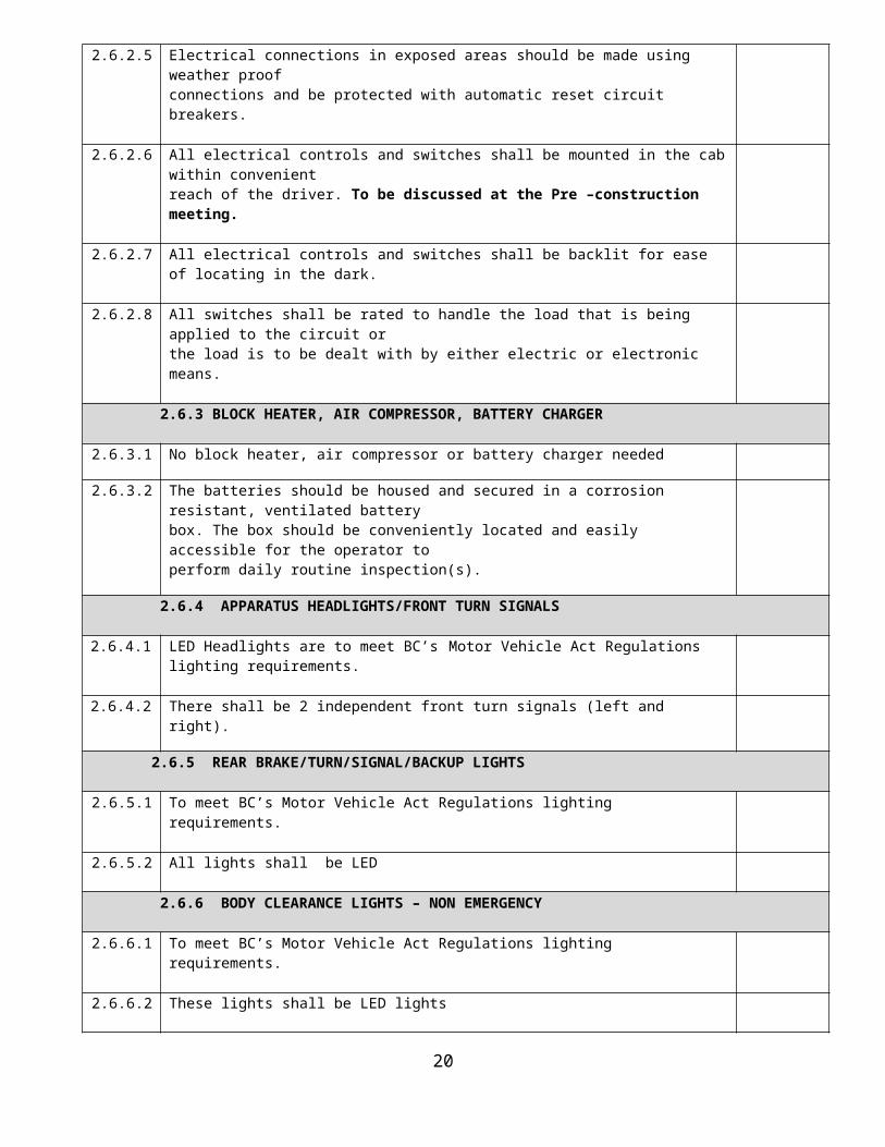
2.6.2.5 Electrical connections in exposed areas should be made using weather proofconnections and be protected with automatic reset circuit breakers.
2.6.2.6 All electrical controls and switches shall be mounted in the cab within convenient14

reach of the driver. To be discussed at the Pre –construction meeting.
2.6.2.7 All electrical controls and switches shall be backlit for ease of locating in the dark.
2.6.2.8 All switches shall be rated to handle the load that is being applied to the circuit orthe load is to be dealt with by either electric or electronic means.
2.6.3 BLOCK HEATER, AIR COMPRESSOR, BATTERY CHARGER
2.6.3.1 No block heater, air compressor or battery charger needed
2.6.3.2 The batteries should be housed and secured in a corrosion resistant, ventilated batterybox. The box should be conveniently located and easily accessible for the operator toperform daily routine inspection(s).
2.6.4 APPARATUS HEADLIGHTS/FRONT TURN SIGNALS
2.6.4.1 LED Headlights are to meet BC’s Motor Vehicle Act Regulations lighting requirements.
2.6.4.2 There shall be 2 independent front turn signals (left and right).
2.6.5 REAR BRAKE/TURN/SIGNAL/BACKUP LIGHTS
2.6.5.1 To meet BC’s Motor Vehicle Act Regulations lighting requirements.
2.6.5.2 All lights shall be LED
2.6.6 BODY CLEARANCE LIGHTS – NON EMERGENCY
2.6.6.1 To meet BC’s Motor Vehicle Act Regulations lighting requirements.
2.6.6.2 These lights shall be LED lights
2.6.6.3 All clearance lights that are exposed to possible damage shall be recessed.
2.6.7 INTERIOR CAB LIGHTING
2.6.7.1 Two individually switched LED lights should be provided. Each light should beequipped with a white and red lens and be provided with an integral switch thatallows the light to be changed between red and white illumination.
2.6.7.2 Mounting location of the lights should be determined by cab design. Two lights shouldbe provided at the front of the cab.
2.6.7.3 All cab lights should be wired to automatically illuminate when a cab door is opened.Ceiling lights should be provided with individual switches for singular operation whenthe cab doors are closed.
2.6.7.4 A master switch within easy reach of the driver and officer’s seated position should beprovided to simultaneously illuminate all ceiling lights.
2.6.8 CAB STEP LIGHTS
2.6.8.1 Doorstep wells should be provided with LED lighting that automatically illuminatewhen the respective door is opened.
2.6.8.2 These lights shall be protected from potential damage.
2.6.8.3 The apparatus should be provided with LED lights that meet NFPA 1901 requirements.
15

2.6.9 SCENE LIGHTS 12 VOLT SYSTEM
2.6.9.1 Scene lights to be LED, preferably FRC Evolution FCA210-V12Two (2) attached to the tank on the driver’s side Two (2) attached to the tank on the passenger’s side.Two (2) attached to the tank on the rear.The type and location to be agreed upon with CBVFR Rep.
2.6.9.2 The rear lights will come on when the apparatus is put into reverse
2.6.9.3 All scene lights to be wired to be turned on from the cab and at the rear of the apparatus.
2.6.10 EMERGENCY LIGHTING AND AUDIBLE WARNING DEVICES
2.6.10.1 The Siren shall be a Federal Signal e-Q2B™ electronic siren to c/w 12 VDC, 200 Watt Speakers, 20 amp draw, 13lbs.(6.1 kg) weight.
2.6.10.2 The Siren location shall be a Federal Signal PA 300
2.6.10.3 A Back-up Alarm with communications is to be installed c/w back-up cameras at theRear of the apparatusAlarms to be a Federal Signal rear camera CAMCCD-REARNTSCThe Back-up camera system shall be wired to come on when the apparatus is put in reverse.
2.6.10.4 Air horns (2) to be installed in the front bumper.
2.6.10.5 Directional arrow sticks to be installed at the rear of the apparatus.
2.6.10.6 Emergency warning lights front, rear and sides that meet NFPA guidelines.These shall be Federal Signal 4x6 QuadraFlare LED exterior lights with red lens
2.6.10.7 The Light bar shall be a Federal Signal product
2.7 PORTABLE TANKS
2.7.1 The apparatus shall come with two (2) hydraulic Zico portable tank systems c/w covers painted white.
2.7.2 The apparatus shall come with two (2) portable tanks c/w aluminium frame with a preferred capacity of 1250 imperial gallons. Preference is for Husky portable tanks.Exact capacity shall be subject to confirmation at the pre-construction meeting.
2.8 BODY CONSTRUCTION DETAIL
2.8.1 GENERAL DETAIL
2.8.1.1 The body shall be fabricated with the highest quality components available andacceptable to the fire service industry. Only new components shall be used in themanufacturing process.
2.8.1.2 Cab and Chassis shall have corrosion protection.
2.8.1.3 Corrosion resistant fasteners and washers will be used as require.
2.8.1.4 The body shall be engineered and designed to provide a low center of gravity.
2.8.1.5 NFPA 1901-fold down steps to be installed as required.
2.8.2 HOSES
16

2.8.2.1 A small hose tray shall be located over the Driver’s side wheel-well to hold forestry-type hose. The size of the tray should be 8’ Long x 2’ Wide x 4” High
2.8.2.2 The inside of the hose tray should be smooth and free of protrusions and obstructions.
2.8.2.3 The hose tray flooring should be fitted with dry lock panels to allow for air movement under the hose.
2.8.2.4 Two (2) 12-foot x 6” suction hoses with NH thread shall be provided and shall be mounted on top of the portable tank system.
2.8.2.5 One (1) 6” floating strainer shall be provided
2.8.3 C0MPARTMENTS GENERAL DESIGN
2.8.3.1. One (1) aluminum compartment shall be mounted on the passenger side of the apparatus under the tank. The size shall be 3’ Long x 3’ High x 26” Deep.
2.8.3.2 The compartment shall be provided with sweep out design floors.
2.8.3.3 The compartment shall be weatherproof and adequately vented.
2.8.3.4 The compartment should be provided with dry lock mat flooring panels.
2.8.3.5 The compartment door shall be roll up style doors c/w Satin Finish.
2.8.3.6 The compartment should be provided with FRC SUNSTRIP LED Strip lighting whichshould be installed with adequate protection to prevent damage during loadingand unloading of the compartment. This shall also apply to the wiring that suppliesthese lights.
2.8.3.7 The Compartment door should be provided with a switch that automatically activates the lighting when the door is opened and turns off the lighting when the door is closed.
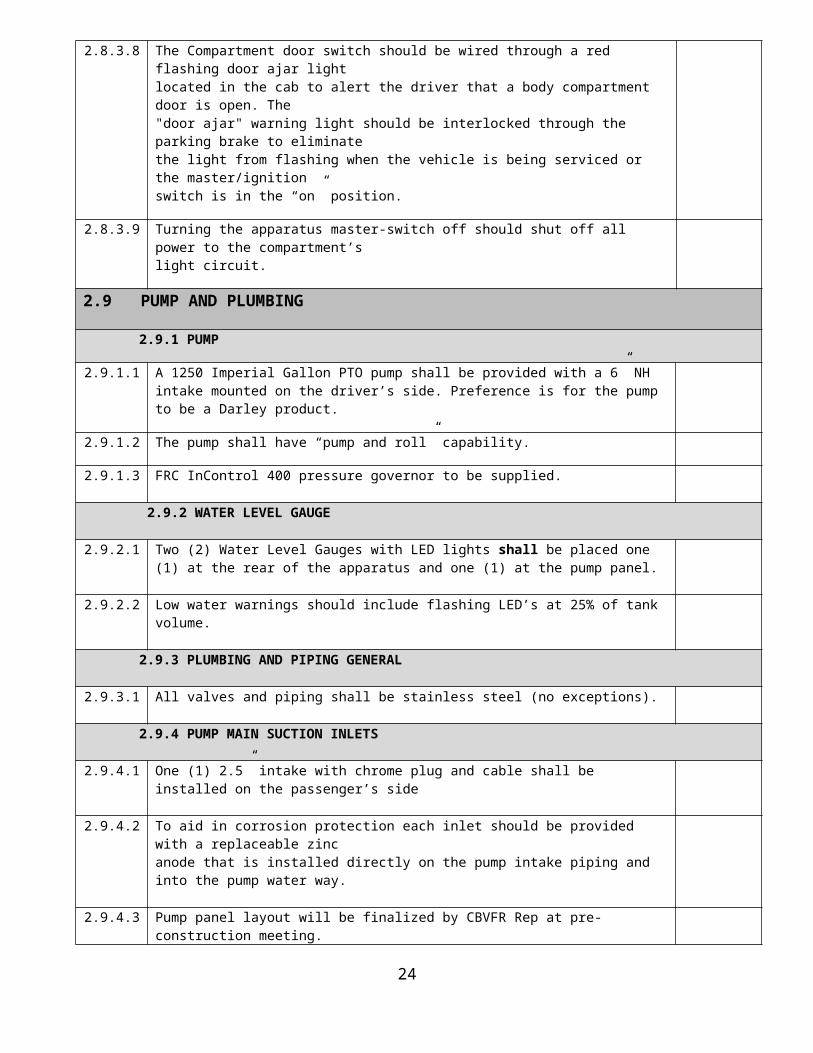
2.8.3.8 The Compartment door switch should be wired through a red flashing door ajar lightlocated in the cab to alert the driver that a body compartment door is open. The"door ajar" warning light should be interlocked through the parking brake to eliminatethe light from flashing when the vehicle is being serviced or the master/ignitionswitch is in the “on” position.
2.8.3.9 Turning the apparatus master-switch off should shut off all power to the compartment’slight circuit.
2.9 PUMP AND PLUMBING
2.9.1 PUMP
2.9.1.1 A 1250 Imperial Gallon PTO pump shall be provided with a 6” NH intake mounted on the driver’s side. Preference is for the pump to be a Darley product.
2.9.1.2 The pump shall have “pump and roll” capability.
2.9.1.3 FRC InControl 400 pressure governor to be supplied.
2.9.2 WATER LEVEL GAUGE
2.9.2.1 Two (2) Water Level Gauges with LED lights shall be placed one (1) at the rear of the apparatus and one (1) at the pump panel.
2.9.2.2 Low water warnings should include flashing LED’s at 25% of tank volume.
2.9.3 PLUMBING AND PIPING GENERAL
17

2.9.3.1 All valves and piping shall be stainless steel (no exceptions).
2.9.4 PUMP MAIN SUCTION INLETS
2.9.4.1 One (1) 2.5” intake with chrome plug and cable shall be installed on the passenger’s side
2.9.4.2 To aid in corrosion protection each inlet should be provided with a replaceable zincanode that is installed directly on the pump intake piping and into the pump water way.
2.9.4.3 Pump panel layout will be finalized by CBVFR Rep at pre-construction meeting.
2.9.5 2 ½” SIDE DISCHARGES
2.9.5.1 Two (2) 2 ½” gated discharges shall be provided, on the passenger side c/w chrome caps and cables.These discharges should be provided withAkron 2 ½”, ¼ turn ball valves with replaceable stainless-steel balls, seals and “o” rings.
2.9.5.2 Discharges should be equipped with a chrome 30-degree adapter, chromeplated rocker lug cap and retaining cable/chain.
2.9.6 FOUR INCH DISCHARGE
2.9.6.1 One four (4) inch (Storz) discharge shall be provided c/w cap and cable. The discharge should be located on the passenger side of the apparatus and should be providedwith an Akron four (4) inch ball valve,
2.9.6.2 The discharge should be equipped with a chrome 30-degree adapter, Storz capwith built in 2 ½” adaptor cap and retaining cable/chain.
2.9.6.3 The discharge should be provided with a bleeder valve assembly to drain waterfrom the pressure line. The bleeder valve should be controlled with a quarter (¼)-turnhandle on the pump panel.
2.9.7 PUMP TO TANK FILL
2.9.7.1 A minimum of a three and one half (3 1/2) inch supply line should be provided from the pump to the tank c/w full flow check valve.
2.9.8 TANK SUPPLY LINE
2.9.8.1 A four (4) inch supply line should be provided from the tank to the pump.
2.9.9 TANK SUPPLY LINE – REAR FILL
2.9.9.1 A four (4) inch rear fill with a 3.5” ball valve to a 4” Storz with adapter to 2.5” female swivel with chrome plug and chain shall be fitted.
2.9.10 DRAIN VALVES
2.9.10.1 The Pump shall have a master drain valve
2.9.10.2 Drain valves should be provided for intake and discharge valves.
2.9.10.3 Drain valves should be positioned horizontally on the forward edge of the left sideouter pump panel.
18

2.9.10.4 All drain valves shall be provided with permanent labels to indicated function.
2.9.11 TANK
2.9.11.1 A 2500 Imperial Gallon wetside tank to be supplied with lifetime warranty
2.9.11.2 Tank construction should be made of thermo plastic c/w life time warranty
2.9.11.3 Both longitudinal and latitudinal baffles should be interlocking and secured insuch a way to minimize water surge during travel. Openings in the baffles shouldbe positioned to allow water flow to NFPA 1901 Chapter 18 standards during fillingor pumping operations.
2.9.11.4 The tank should be mounted on cushions to isolate the tank from road shock andvibration and be completely removable without disturbing or dismounting theapparatus body. Wood shall not be used.
2.9.11.5 Access to the interior of the tank for cleaning is required NFPA 1901 A18.2.2.
2.9.11.6 A three (3) way dump shall be provided at the rear of the tank (A.H. Stock) with electric actuators and shall be stainless steel with extensions.
2.9.11.7 A ladder shall be mounted on the rear of the tank for access to the tank. The ladder shall be manufactured of either aluminum or stainless steel.
2.9.12 PUMP CERTIFICATION AND TESTING
2.9.12.1 A third party company holding ULC test certification shall conduct ULC testing ofthe pump system in accordance with NFPA 1901 16.13
2.9.12.2 A test plate, installed at the pump panel, should provide the rated discharges andpressures together the speed of the engine as determined by the certification test,and the no-load governed speed of the engine.
2.9.12.3 A Certificate of Inspection certifying performance of the pump and all relatedcomponents should be provided at time of delivery. Additional certificationdocuments should include, but not limited to, Certificate of Pump Performancefrom the pump manufacturer.
2.10 FRAME SPECIFICATION
2.10.1 FRAME DESIGN
2.10.1.1 The Frame Design will be the sole responsibility of the OEM.Frame shall be painted or treated with a corrosion resistant coating.
2.10.2 FRONT BUMPER
2.10.2.1 Two front and two rear tow eyes of sufficient strength to permit the recovery of afully loaded apparatus should be provided.
2.11 STEERING
2.11.1 STEERING COLUMN
2.11.1.1 The Steering column shall be tilt/telescoping.
2.11.2 STEERING GEOMETRY
19
2.11.2.1 Details of the Steering radius shall be provided by the manufacturer
2.11.2.2 Details of the Swing radius shall be provided by the manufacturer.
2.12 AXLES/SUSPENSION
2.12.1 FRONT AXLE
2.12.1.1 Details of the Axle capacity shall be provided by the manufacturer.
2.12.1.2 Details of the Suspension shall be provided by the manufacturer.
2.12.1.3 The Front wheel bearings to be oil lubed.
2.12.2 REAR AXLE
2.12.2.1 Details of the Axle capacity shall be provided by the manufacturer.
2.12.2.2 Details of the Suspension shall be provided by the manufacturer.
2.12.3 CLEARANCE ANGLES
2.12.3.1 An angle of approach and departure of at least 8 degrees shall be maintained at thefront and rear of the vehicle when it is loaded to the estimated in-service weight.
2.13 RIMS/TIRES
2.13.1 RIMS
2.13.1.1 The apparatus shall have aluminum wheels and caps.
2.13.1.2 The Rims and Tires shall meet the load bearing requirements as laid out inNFPA 1901 12.3.2.1.
2.13.2 TIRES
2.13.2.1 To be recommended by Proponent and approved by District at pre-construction meeting
2.14 BRAKING SYSTEM
2.14.1 AIR BRAKESYSTEM
2.14.1.1 Air brakes system shall comply to NFPA 1901 12.3.1.2 and 12.3.2.1
2.14.1.2 Air compressor volume to be no less than 18.7 cfm.
2.14.1.3 The Brake system shall be c/w an air dryer.
2.14.1.4 Brake Auto moisture ejectors and bleed taps shall be provided on all air tanks.Shall have front brake lockup assist.
2.15 PAINT
2.15.1 The apparatus shall be white in color with a 20” Safety Yellow (paint code BMW-101)stripe starting on the left side and wrapping around the front of the apparatus anddown the right side of the apparatus. The chassis frame assembly shall be treated as per 13.1.1. of this document andthe interior of the body compartments shall be painted white.
2.15.2 The apparatus shall have reflective striping that meets the NFPA 1901 15.9.3
20

requirements.The rear of the tank shall be covered in chevron striping which shall be red and green
2.16 TECHNICAL DATA
2.16.1 IDENTIFICATION PLATE
Note: The following information shall be provided as a minimum, permanently marked and in a Conspicuous and protected location.
2.16.1.1 Vehicle identification number.
2.16.1.2 Gross Vehicle Weight Ratings.
2.16.1.3 The manufacturer’s Canada Motor Vehicle Safety Standards certification sticker.
2.16.1.4 A data decal containing fluid/oil type and capacity for the following: Engine oil Transmission oil Coolant Power steering Differential oil
2.16.2 WARNING AND INSTRUCTION PLATES
2.16.2.1 All required Safety and Personnel Protection Warning and Safety plates and signsare to comply with NFPA 4.10.2.
3.0 Bid Evaluation
3.1 Proposal Bid Sheet
COWICHAN BAY IMPROVEMENT DISTRICT
Proposal Bid Sheet for New Water Tender Fire Apparatus
21

The undersigned Proponent has carefully examined the Conditions, Conceptual Specifications, Mandatory Requirements and Additional Equipment or Features for the New Water Tender Fire Apparatus requested and will construct or provide and deliver the apparatus requested.
This proposal is valid for: _____ days and shall expire on ______________________2019
Description PriceFor the design, construction and delivery of one (1) New Water Tender Fire Apparatus on a Supplied Chassis $
Import Duty and/or Excise Tax $
5% GST $
7% PST $
Environmental Taxes & Levies $
TOTAL $
Note: Please include a delivery lead-time with your submission:
Delivery date after acceptance of Proposal: ______________________________
PROPONENT NAME: _________________________________________________________________
ADDRESS: _________________________________________________________________________
CITY: ________________________________________ POSTAL/ZIP CODE: ___________________
PRIMARY CONTACT EMAIL:______________________________ WEBSITE: __________________
PRIMARY CONTACT PHONE: _____________________________ FAX: _______________________
SIGNATURE OF PROPONENT: ____________________________ PRINT NAME: _______________
**MUST BE AN OFFICIAL SIGNATORY OF COMPANY**
3.2 Selection Criteria
3.2.1 Price (30 points)
The lowest or any proposal will not necessarily be accepted.
22

The District reserves the right to accept any or none of the proposals submitted and will evaluate proposals based on the best value and not necessarily the lowest cost.
3.2.2 Proponent qualifications and experience (35 points)
The evaluation of this factor shall take into consideration the proponent’s experience and reliability as outlined in Section 1.6 of this RFP.
Of importance to the District is the ability of the proponent to meet the
specifications, the delivery time and to have references that reflect the proponent’s history of demonstrating quality workmanship.
3.2.3 Training, Warranty, Service and Repair (15 points)
These criteria will be assessed on the information received in response to Sections 1.9, 1.11 and 1.12 of the RFP.
3.2.4 Proposal Quality and Clarity (20 points)
Notes:
Acceptance of any proposal will be subject to budgetary considerations, and Cowichan Bay Improvement District Board of Trustees approval.
An evaluation committee will be reviewing all proposal documents.
4.0 Attachments
4.1 Attachment “A”
4.1.1. Current Cowichan Bay Fire Rescue Paint Scheme
23
The Attached picture is provided to reflect the desired paint scheme, stripingand decaling
4.1.2 Rear Dump System
The attached photograph shows the desired layout of the system.
4.1.3 Apparatus Layout
The attached photograph shows the basic lay-out of the apparatus components requested with this RFP.
4.2 Attachment “B” - Documentation including manuals
The following documentation, supporting the apparatus, is to be provided at acceptance in Cowichan Bay:
A. One maintenance manual should be provided including a manual for auxiliary equipment.
B. One Operator’s manual should be provided including a manual for auxiliary equipment.
C. ‘As built’ drawings for all air and electrical systems including any modifications shall be provided.
D. One colored copy of the apparatus specific wiring diagrams shall be supplied with the apparatus and clearly detail interfaces and routing of the manufacture’s electrical circuit(s) of the cab and chassis OEM electrical system.
4.3 Attachment “C”
4.3.1 Paint Scheme
24

4.3.2 Rear Dump System
4.3.3 Apparatus Layout
25

4.4. Attachment “D” – Optional Equipment
Item Quantity Item Description
1. 1 Monitor to be mounted on the Passenger side, beside tank. Monitor shall be an Akron Fire Fox low flow or equivalent with controls in the cab.
26