Embed Size (px)
Citation preview
ARTICLE IN PRESS
Journal ofVisual Languages & ComputingJournal of Visual Languages and Computing
17 (2006) 78–105
1045-926X/$
doi:10.1016/j
$Research
Integration o
UML (UML�CorrespoE-mail ad
(P. Ziemann)
www.elsevier.com/locate/jvlc
On translating UML models into graphtransformation systems$
Karsten Holscher�, Paul Ziemann, Martin Gogolla
Department of Computer Science, University of Bremen, Bremen, Germany
Accepted 9 November 2005
Abstract
In this paper we present a concept of a rigorous approach that provides a formal semantics for a
fundamental subset of UML. This semantics is derived by translating a given UML model into a
graph transformation system, allowing modelers to actually execute their UML model. The graph
transformation system comprises graph transformation rules and a working graph which represents
the current state of the modeled system. In order to support UML models which use OCL, we
introduce a specific graph transformation approach that incorporates full OCL in the common UML
fashion. The considered UML subset is defined by means of a metamodel similar to the UML 1.5
metamodel. The concept of a system state that represents the state of the system at a specific point in
time during execution is likewise introduced by means of a metamodel. The simulated system run is
performed by applying graph transformation rules on the working graph. The approach has been
implemented in a research prototype which allows the modeler to execute the specified model and to
validate the basic aspects of the model in an early software development phase.
r 2005 Elsevier Ltd. All rights reserved.
Keywords: Graph transformation; UML semantics; Validation; CASE tool
- see front matter r 2005 Elsevier Ltd. All rights reserved.
.jvlc.2005.11.001
partially supported by the EC Research Training Network SegraVis (Syntactic and Semantic
f Visual Modeling Techniques) and the project Abstract Implementation of and Documentation with
-AID) funded by the German Research Foundation (DFG).
nding author.
dresses: [email protected] (K. Holscher), [email protected]
, [email protected] (M. Gogolla).

ARTICLE IN PRESSK. Holscher et al. / Journal of Visual Languages and Computing 17 (2006) 78–105 79
1. Introduction
The Unified Modeling Language (UML) has recently become a standard for themodeling of object-oriented software systems. It comprises a set of different diagram types,each of them describing particular aspects of software artifacts. The syntax of thesediagrams is described by means of a metamodel in [1], denoted as class diagrams. Since theclass diagram itself is defined in a cyclic way by the metamodel, the metamodel definitionof UML diagrams can only be considered semi-formal. Furthermore the semantics ofUML components is only expressed in natural language. In order to overcome thelimitations of a purely graphical notation, the UML has been enhanced by the textualObject Constraint Language (OCL). The OCL is also semi-formally defined in [1]. Aformal syntax and semantics for UML class diagrams as well as OCL has been introducedin [2], which is also included in the accepted OCL 2.0 submission to the OMG [3].
This work presents a concept for obtaining a formal semantics not only for classdiagrams but for further basic diagram types (use case, object, statechart and interactiondiagrams) belonging to the UML standard 1.5. We stick to UML 1.5 but UML 2.0likewise includes the UML concepts covered by us, albeit some details and the naminghave been changed in some cases. In particular, UML 1.5 collaboration diagrams arecalled communication diagrams in UML 2.0. Graph transformation (cf. [4–6]) is employedas the formal foundation of this new integrating semantics.
Our approach provides a framework for an automatic translation of a UML model into agraph transformation system. The UML model may comprise a subset of the diagram typesmentioned above and may furthermore include OCL expressions. The graph transformationsystem consists of graph transformation rules and a so-called working graph, hence calledsystem state graph. This graph represents the state of the modeled system at a given point oftime. The changes of the system state during an execution of the model are simulated by theapplication of graph transformation rules on the system state graph. In this way a stepwiseexecution of the model can be simulated. As no formal semantics is given for the UML, theeffects of the model execution rely on a number of assumptions, especially regarding theintegration of the mentioned diagram types and their use in practice.
We have enhanced the graph transformation foundation with OCL expressions. Theseexpressions navigate the current system state and can be used as application conditions,which determine whether a certain rule may or may not be applied. OCL expressions canalso be used to calculate new attribute values in the right-hand side of graphtransformation rules. Additionally, OCL is used as query language for inspecting thecurrent system state. The use of OCL as a textual notation also leads to the benefit of morecompact graphs in most cases.
The representation of a UML model as a graph transformation system is used here tovalidate the system before actually implementing it. Employing graph transformation forthe simulation of the modeled system has the benefit of a visualized system run. Thesimulation allows modelers to compare the behavior of the system with their expectations.Given a system state a, they can easily gain an understanding of the actions that arepossible in this state. Furthermore our concept also supports goal-oriented tests regardingthe question whether a given state o is reachable from state a (though this is generallyundecidable as it is equivalent to the word problem for any kind of language). Theapproach also enables the modeler to check what states can be derived from the state a.The integration of OCL allows for the checking of OCL invariants during system state

ARTICLE IN PRESSK. Holscher et al. / Journal of Visual Languages and Computing 17 (2006) 78–10580
evolutions. The modeler may test whether an invariant that holds in state a still holds in aderived system state o.Currently, a prototypic validation system is implemented for our approach which
generates the graph transformation rules for a given model and allows to interactivelyexecute and visualize the modeled system. This prototype can be used by a modeler in anearly stage of a software development process in order to acquire additional insight intothe newly designed system.A full formal and elaborated description of our concepts can be found in the Ph.D.
thesis [7], where the integrated system specification and the translation into a graphtransformation system as well as the implemented prototype UGT are discussed: in thecentral part of that work, the translation of an integrated UML model into a graphtransformation system is described in detail. The concept of system states, which arerepresented by graphs and transformed by graph transformation rules, is defined. Thethesis explains how to derive the initial system state, which is the system state at thebeginning of a system run, from the given object and statechart diagrams. The graphtransformation rules are described subsequently. The work describes the rule for initiatinguse cases, which is independent of the UML model. Also independent of the model are therules performing predefined operations like creating objects or setting attributes. The paperdescribes rules executing object operations, i.e., operations the user has declared in a classdiagram and specified by an interaction diagram. Use cases are treated as operations thatdo not belong to a class (use case operations), and therefore the rules realizing use cases areconstructed in the same way. Nodes that are not needed anymore are deleted from thesystem state by the garbage collection rule. Finally, the work clarifies the way classgeneralization and thus inheritance of attributes and operations are covered. For alldetails, we again refer to the original work [7].The structure of the rest of this paper is as follows. In the next section we present some
related work, followed by a section in which the concepts of graph transformation weemploy are introduced. The covered UML features of the model are presented andexplained using a simple example in Section 4. Section 5 deals with the detailed descriptionof the system state concept. An overview of the translation of the model into a graphtransformation system is presented in Section 6 mostly by example, followed by a briefintroduction to the fundamental architecture of the prototypic implementation. The papercloses with concluding remarks in Section 7.
2. Related work
Since UML lacks a formal mathematical foundation, several works can be found thataddress this issue. Different formalisms are employed to provide a formal semantics forparts of UML. In [8] a translation of UML into a partial Object-Z specification ispresented. The work in [9–11] discusses the specification of UML semantics on themetamodel level. Ref. [12] presents a formal semantics of UML activities based on Petri-nets. Streams are employed as semantic domain of a UML model in [13]. The works [14,15]focus on high level semantics based on temporal and deontic logic, respectively. ThexUML approach presented in [16] defines a subset of UML for rigorous object-orientedmodeling and provides an operational semantics for supported diagram types.There are also several other works aiming at defining a semantics for parts of UML using
graph transformation. In [17], an integrated semantics is given for a large part of UML.

ARTICLE IN PRESSK. Holscher et al. / Journal of Visual Languages and Computing 17 (2006) 78–105 81
However, interaction diagrams and OCL are not considered. Their approach is extendedwith interaction diagrams on instance level in [18]. Operations are still specified by singlerules, that is, all operations have to be atomic. More efforts exist considering isolated partsof UML. In [19], collaborations are translated into transformation rules, wherecollaborations are interpreted as visual queries using pattern matching. A formal semanticsfor UML statecharts is presented for example in [20,21]. The Fujaba tool suite [22] supportsgraphical object-oriented software design and automatic code generation from storydiagrams. These diagrams combine behavioral UML diagrams and additional features.Additional approaches for consistency analysis of UML models can be found. In [23], givenUML real time models are refined using graph transformation rules and their consistency ischecked in the semantic domain of CSP. Ref. [24] studies questions concerning therealization and the semantics of UML packages in connection with a graph-based tool. Ref.[25] addresses the consistency analysis between UML class and sequence diagrams based ongraph transformation. Parts of the UML semantics have also been defined with AbstractState Machines (ASMs). Work includes the UML semantics definition for single diagramlike statechart [26,27] and activity diagrams [28] and the study of special aspects likeconstraints [29] or liveness [30]. Furthermore, ASMs have been used for the validation ofUML models [31] and the implementation of a UML virtual machine [32]. However, acomprehensive integrating treatment of these different works seems to be missing.
All these works have in common, that they mostly address isolated parts of UML. Weare not aware of an approach handling a collection of UML diagrams as presented in thiswork together with the integration of OCL. In particular the incorporation of use cases isnew. In [33] use cases are described precisely by so-called operation schemata includingOCL pre- and postconditions but the connection to other UML diagrams is left open.
The main benefit of our approach is (A) the integrated coverage of a substantial part ofthe UML, (B) a minimal impedance mismatch between the original UML model and oursemantical domain, in particular the system state and (C) the possibility to validate andtest on the model level. As the system evolves, our system state graph changes accordingly,always in tight closeness to the actual visual UML model. The system state may beunderstood as a UML object diagram. Analogously to the system state, our rules, e.g., forstatechart transitions, bear strong similarities to the original UML descriptions. Thecloseness between UML model and the semantical domain allows to give better feedbackto the modeler because the modified system state can again be understood as a UMLdescription. Our approach also makes fewer assumptions regarding the semantics of themodel as, for instance, other approaches and code generators have to make. In order toimprove the quality of software, the application of code generators is an accepted means inthe industrial software development. As direct tests of the model are not yet supported, thegenerated code is debugged. Should errors occur during tests, currently the generated codeis changed. But in our approach, it is possible to directly perform tests on the level of themodel without having to deal with generated code. Our approach also allows for an easierhandling of future extensions and changes of the model, since only the model itself and notthe generated code has to be changed.
3. Graph transformation
Graphs are a frequently used means to visualize complex information, like the structureof computer networks or database designs. Graph transformation allows local changes on

ARTICLE IN PRESSK. Holscher et al. / Journal of Visual Languages and Computing 17 (2006) 78–10582
such a graph by applying graph transformation rules. A very obvious application domainfor graph transformation is the field of visual modeling, like UML. A model may betransformed into another model of the same visual language (e.g. refinement orrefactoring) or into a model of a different visual language (cf. MDA). A graphtransformation system may also serve as a semantic domain, as is the case in our approach.Various well-studied graph transformation approaches can be found in the literature.Basically a graph consists of a set of vertices, a set of edges, and mappings s; t that assign
a source and a target vertex to every edge. Furthermore vertices and edges are mapped intoa given alphabet, providing edge and vertex labels. The label alphabet includes the invisiblelabel, which is used for vertices or edges whenever they are supposed to carry no label.Since we want to represent more sophisticated structures where objects may also contain
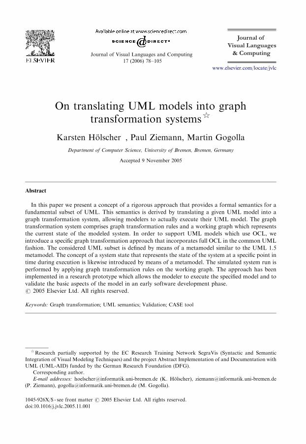
attributes, we enhance this graph model with a concept for vertex attributation.Analogously to the presentation in [34], data values are represented as special data valuenodes, all of which are present in the attributed graph. The elements of the combined set ofdata value nodes and ‘‘usual’’ vertices will be called nodes. The source, target and labelmappings then apply to the set of all nodes, where the data value nodes are labeled withtheir respective type. In our approach the data value nodes are the elements of themathematical sets Z;R, ftrue; falseg, A� (for a given alphabet A) representing the OCLtypes Integer, Real, Boolean, and String, respectively. An attribute of a vertex is thenrepresented by an edge from that vertex to the corresponding data value node. This edge islabeled with the name of the attribute. Since the carrier sets are usually infinite, data valuenodes are omitted in pictures unless they have incoming edges. In this case we call the datavalue nodes visible.In figures we employ a simplified notation of vertex-attributed graphs by depicting them
in a UML-like fashion. Vertices are depicted as rectangles with two compartments. In theupper compartment the vertex identifier and its label can be found, separated by a colon.Here the identifier is used as a mere reference for easier description of a graph. In the lowercompartment the attribute names together with their concrete values are depicted one perline. Fig. 1 shows an attributed graph with two vertices and three data value nodes on theleft-hand side, and the corresponding simplified version of that graph on the right-hand side.In this paper a graph transformation rule consists of three graphs L;K ;R, called left-
hand side, common part, and right-hand side, respectively. In order to increase theflexibility of rules, the data value nodes of the left-hand side are extended by a set X ofvariables. Thus it is possible to specify variable values instead of concrete constant valuesfor attributes in the left-hand side of a rule.Attribute data value nodes of the right-hand side are somewhat more complex in order
to allow for attribute value computation. We assume that every concrete data value isrepresented syntactically by a constant symbol. Let B ¼ ðBiÞ be the family of theseconstant symbols, indexed by the basic types listed above. Furthermore let SBðX Þ be the setof expressions over B and X which is defined as usual: an expression is either a constantc 2 B, or a variable x 2 X , or it is of the form oðt1; t2; . . . tnÞ with o being an operationsymbol and the arguments ti 2 SBðX Þ being expressions of suitable types. In our case weuse the usual operations, e.g. arithmetic operations on numbers, sign manipulation and thelike. The data value nodes of the right-hand side are then all elements of SBðX Þ. In figuresthe operations are written in infix notation, i.e. þð5;xÞ becomes 5þ x.The two rule sides L and R are connected by a common part K, which is a subgraph of
both L and R. K is a subgraph of L if the nodes and edges of K are subsets of the nodes and
ARTICLE IN PRESS
worksAt
G G
"manager":String 10000:Integer
position salary
e:Employee
c : Company
worksAt
location
"Bremen":String
e:Employee
position = "manager"salary = 10000
c:Company
location = "Bremen"
Fig. 1. An attributed graph in two different notations.
K. Holscher et al. / Journal of Visual Languages and Computing 17 (2006) 78–105 83
edges of L, respectively, and the nodes and edges coincide in their respective label, sourceand target mappings. Informally speaking a rule is applied to a given graph G (called host
graph) by finding a situation in G that is specified by L. Then the part corresponding toL� K is deleted from G and R� K is glued to G. In figures depicting rules, the identifier ofvertices is used in order to indicate parts of the gluing graph K, i.e. a vertex with the sameidentifier in the left-hand side and the right-hand side is an element that has to bepreserved. Elements without identifiers are either deleted from (in the left-hand side) oradded to the graph (in the right-hand side).
In order to find a situation specified by L in a host graph G, a so-called match is needed,i.e. a structure-preserving mapping (called graph morphism) of L into G. A graphmorphism maps the nodes and edges of one graph to the nodes and edges of the othergraph such that labels and source and target nodes are preserved (ignoring isolated datavalue nodes). For our purposes we demand an injective match, i.e. equivalent imagesrequire equivalent preimages. Since no variable set is present in the host graph, variablevalue nodes from X may be mapped to any data value node in the host graph, providedthat the structural properties are preserved. Fig. 2 shows a rule with a variable sal in theleft-hand side and a match of L in a host graph G. The match determines a variablebinding for the variable data value nodes in L; for instance, mðsalÞ ¼ 10 000 in Fig. 2. Thesame variable may be used more than once in the left-hand side via several edges leading tothe corresponding variable data node. In figures, variables are printed in italics.
A rule r ¼ ðL;K ;RÞ is then applied to G by deleting mðL� KÞ from G. This is done byremoving the vertices and the edges, together with possible dangling edges, i.e. edges withsource or target in mðL� KÞ. This yields an intermediate graph Z. If R contains visibledata value nodes from SBðX Þ, their expressions are evaluated using the variable binding m.If the expression is of the form x with x 2 X , the edge leading to x is deleted and a new onewith the same label leading to mðxÞ is created. If the expression is of the formoðt1; t2; . . . ; tnÞ, the operation and parameters are interpreted in the usual way (in case ofti 2 X using mðtiÞ) and the edge leading to that value node is replaced with an edge (againwith the same label) leading to the result of the evaluated expression. This evaluation yieldsan instance R0 of the right-hand side which has only visible data value nodes from the basic

ARTICLE IN PRESS
G
L RK
worksAt worksAt
Z H
emp : Employee
salary = sal
: Employee
position = "manager"salary = 10000
worksAt
: Company
location = "Bremen"
emp : Employee emp : Employee
: Employee : Employee
position = "manager" position = "manager"
: Company
location = "Bremen"
: Company
location = "Bremen"
salary = 10100
salary = sal +100
Fig. 2. A rule ðL;K ;RÞ, a match L! G and the application to G.
K. Holscher et al. / Journal of Visual Languages and Computing 17 (2006) 78–10584
sets. Now R0 � K is glued to Z. This is done by adding all vertices and edges from R0 � K
to Z, possibly gluing new edges to already present nodes, i.e. if sðeÞ 2 K for an edge e ofR0 � K , then e is connected to mðsðeÞÞ (and analogously for tðeÞ 2 K). Fig. 2 shows theapplication of a rule ðL;K ;RÞ by depicting G, the intermediate graph Z and the resultgraph H after successful rule application. The edge labeled salary is not part of K, thus itis deleted in Z and added to H as a new edge present in R but not in R0 � K. The data valuenode 10000 becomes invisible in Z, and the data value node 10100 becomes visible in H.Besides specifying a desired situation in the left-hand side of a rule, it is sometimes useful
to specify a situation in the host graph that is not wanted. This is realized by a negative
application condition (NAC). An NAC is a graph that extends parts of the left-hand side,i.e. a (possibly even empty) subgraph of L is a subgraph of such a graph NAC. If the matchof L in the host graph G can be extended to a match of NAC in G, then the rule cannot beapplied. Fig. 3 shows the rule from Fig. 2 together with an additional NAC that preventsthe rule from application if the salary to be increased is exactly 100 000.In our approach, we also employ a simpler form of the so-called transformation units
[35,36]. In our case a transformation unit comprises a set of local rules and a controlcondition. To apply a transformation unit to a given graph, the new graph is derived byapplying the local rules according to the control condition. The semantics of the operatorsused inside control conditions will be explained where they occur in the following sections.We regard the application of a transformation unit as an atomic operation, similar to onerule application, since the intermediate graphs are not of any interest. For our purposes thetransformation units are constructed in such a way that either their first rule is not

ARTICLE IN PRESS
L R N
emp:Employee emp:Employee emp:Employee
salary=sal salary=sal +100 salary = 100000
Fig. 3. A graph transformation rule with an NAC.
K. Holscher et al. / Journal of Visual Languages and Computing 17 (2006) 78–105 85
applicable or the whole unit can be applied successfully.1 In our approach the semantics ofcontrol conditions differs from the original definition in that a failed application of acontrol condition yields the original (unchanged) graph. In the next section we provide anoverview of the UML features that are covered by our approach supported by a very basicsample model.
4. Covered UML features
We cover substantial aspects of the following UML features: use case, class, object,statechart, and interaction diagrams (collaboration and sequence diagrams) and last butnot least full OCL.
We support class diagrams for defining the structure, and interaction diagrams forrealizing operations declared in the class diagram. An interaction diagram contains asequence of messages calling either an operation of a class that in turn is realized by aninteraction diagram or calling a predefined functionality like creating an object or settingan attribute value.
Use cases are likewise realized by interaction diagrams. A use case resp. its realizationstates which operations could be called by a user of the eventually implemented system andin which order this is done. Statechart diagrams specify the order in which operations onan object may be executed. The kind of statechart diagrams we support are so-calledprotocol machines, i.e., statechart diagrams with guards and events used as transitionlabels. Object diagrams are used to specify the system state to start the evolution with andto represent a part of the current state of the system.
Fig. 4 gives an overview of the connections between the central concepts. We considerone class diagram and one use case diagram. This is no limitation because in our approachmultiple class diagrams can be merged to one, and so can use case diagrams. Each class haszero or more operations. A use case is associated with exactly one operation that is notassociated with a class. Each operation is realized by an interaction specified in aninteraction diagram. An interaction contains messages, which are either predefined (e.g. forcreating an object or setting an attribute value) or which call an operation of a class. Foreach class there can be one state machine specified in a statechart diagram. An objectdiagram instantiates the class diagram. We illustrate the usage and interplay of the
1A property like that would be hard to achieve for transformation units in general, but in the context of our
work only a very small subset of all possible transformation unit constructions is needed. Due to this fact and the
rule construction scheme in general, the mentioned property can be guaranteed.

ARTICLE IN PRESS
1 0..1
0..1
0..11..*
0..1
0..1*
1
*
{xor}
1..*
*
1
instanceObject
UseCase
PredefinedMessage
Message
OpCallMessage
type context
realizedOp
Class
Operation
behaviorStateMachine
realization
Interaction
Fig. 4. Connection between central modeling concepts.
K. Holscher et al. / Journal of Visual Languages and Computing 17 (2006) 78–10586
diagrams by a representative excerpt of an example UML model of a drive-throughrestaurant.The drive-through system consists of clients who enqueue themselves in the queue of a
drive-through restaurant, submit orders, pay for meals, and eat. The restaurant producesmeals and serves them to the clients.The class diagram in Fig. 5 defines the structure of our example system. The class
DriveThrough represents drive-through restaurants. A drive-through is visited by severalclients who await being served. This is specified by the association Visit betweenDriveThrough and Client. The two additional associations First and Last mark one clientas the first one in the queue and another client as the last one. The order in the queue isreflected by the association Queue. Clients can select an order by connecting to an Order
object by the association Submit. The drive-through is then expected to produce a Meal
object corresponding to the order. This correspondence is managed by the attributes name
resp. meal of the two classes. A meal that has been produced and is ready to be served isconnected to the drive-through by the association ToServe. A served meal is connected toa client by the association ToEat until it is eaten.A use case diagram is used to show on a high level the possible interactions of a user with
the eventually implemented system. A use case is a sequence of operations the user maycall. The use case diagram only shows the names of the use cases; the correspondingsequence is specified in an interaction diagram. In our example there is a use casestartDriveThrough which enables the user to control the drive-through, and a use casecallClientToEat for ‘‘telling’’ an idle client to queue himself in the queue of a drive-throughand submit an order. The user of the drive-through system is modeled as supervisor (seeFig. 6).Before elaborating on the relatively low-level interaction diagrams, we take a look at
statechart diagrams, which are used in a more high-level way in our approach. A statechartdiagram specifies the states an object of a certain class can be in, which operations may be

ARTICLE IN PRESS
Supervisor
callClientToEat
startDriveThrough
Fig. 6. A use case diagram.
start()serve()updateFirst()updateLast()
First
ToServe
Visit
Last
queueAndOrder()pay()eat()ready(meal:Meal) Queue
ToEat
0. .1
0. .1
0..1
*
0..1
*0..1
0..1
0..1
0..1
lastOf
0..1
0..1
0..1
firstOf
DriveThrough
Meal
name:String
0..1
first
last
Client
previous
next
Submit
Order
meal:String
Fig. 5. A class diagram.
K. Holscher et al. / Journal of Visual Languages and Computing 17 (2006) 78–105 87
executed in which state, and how the execution of an operation changes the state of theobject the operation is running on. We assume that operations which do not occur in thestatechart for the corresponding class are allowed to be executed in every state.
The statechart diagram in Fig. 7 specifies the states a client can be in: idle, waiting andhasPaid. The initial state is the state idle, which means that once a client object is created itis in state idle. It is also specified here that executing the operation queueAndOrder isallowed only in state idle and changes the state to waiting. The operation pay then changesthe state to hasPaid and the operation eat then changes the state back to idle.
As mentioned above, the operation sequences that constitute use cases are specified ininteraction diagrams. In this case we use collaboration diagrams but sequence diagramscould also be used, as explained below.
The collaboration diagram shown in Fig. 8 realizes the use case callClientToEat byspecifying the messages the supervisor can send. In this case we have only oneOpCallMessage as referred to in the metamodel in Fig. 4. The message (numbered with1) is sent to a classifier role representing a client and calls its operation queueAndOrder().Other messages 2, 3, etc. could have followed for a larger use case. The sequence numbersat the beginning of the messages specify the order in which they are sent.

ARTICLE IN PRESS
queueAndOrder()idle waiting
pay()eat()
hasPaid
Fig. 7. A statechart diagram for the class Client.
callClientToEat
1: queueAndOrder()
Supervisor 1.1: queue()1.2: order()
«self»
c : Client
Fig. 8. A collaboration diagram realizing the use case callClientToEat and the operation queueAndOrder of the
class Client.
K. Holscher et al. / Journal of Visual Languages and Computing 17 (2006) 78–10588
The sequence numbers are nested in different depths to allow the realization of severaloperations in a single diagram. The present collaboration diagram also specifies theoperation queueAndOrder() on Client which is realized by first calling queue() (sequencenumber 1.1) and then order() (sequence number 1.2) on the object that receives themessage.Fig. 9 shows a more complex collaboration diagram. The operation serve() is called by a
supervisor on a drive-through object, which in turn calls several other operations bysending the messages 1.1 to 1.5. Message 1.4 calls the operation ready(meal) on a client,which in turn is realized by the messages 1.4.1 and 1.4.2. The other messages calloperations with a predefined effect like creating an object or setting an attribute value.The nodes in a collaboration diagram are called classifier roles. They represent objects in
the system state. The edges are association roles representing links. A message that is sentvia an association role that is stereotyped with � local� means that the receivingclassifier role is stored in a local variable. The name of the variable is specified by the rolename. If the association has no stereotype, the interaction is underspecified. In this case,the message is sent to an arbitrary object of the specified class that is linked to the senderobject by a link of the specified association. A future version of the aforementioned toolwill alert the modeler of this underspecification and permit them to choose an actualreceiver object.The message 1.2: link(ToServe) specifies that a link instantiating the association
ToServe has to be created. Usually a link message needs parameters specifying theconcrete objects that have to be linked as well as their association roles (especially if thearity of one association end is greater than one—in this case it is not always obvious whichobjects have to be linked). In the context of the given model it is not necessary to provide

ARTICLE IN PRESS
1:serve()
Actor : First
1.4: ready(meal)
d:DriveThrough
1.1: create()
c:Client
1.2: link(ToServe)
1.3: setAttribute(name=self.first.order.meal)
1.5: unlink(ToServe)
: ToEat
«local»
meal«local» meal
m:Meal
1.4.2: link()
: Submit
1.4.1:unlink()o:Order
Fig. 9. A collaboration diagram realizing the operations DriveThrough::serve() and Client::ready(meal:Meal).
K. Holscher et al. / Journal of Visual Languages and Computing 17 (2006) 78–105 89
this information, since ToServe is specified to associate one object of type DriveThrough
with an object of type Meal. The actual classifier roles to be linked are in this case thesender d and the receiver m. In case of the link message 1.4.2: link() it is analogouslydetermined which objects will be linked in what way. The usage of an instance of theassociation ToEat as a channel for the message in this case also determines that the link tobe created will instantiate the association ToEat without explicitly providing it as aparameter.
Object diagrams are used in our approach to specify a part of an initial system state, thatis the system state the modeler wants to start the system run with. The object diagram inFig. 10 depicts such an initial system state for the drive-through example. There are onedrive-through and four clients. Three of them are visiting the drive-through and havealready ordered. The state of the objects is specified by attached notes.
Having specified the relevant parts of the system to be implemented, the modeler mayexecute the DriveThrough model to check for design flaws. Given the system statecorresponding to the initial object diagram in Fig. 10, it could be checked whether client c4can be inserted into the queue in the right position. It could also be checked whether c4 canbe served, or whether the other three clients may submit further orders. A test could alsoreveal, whether a state is reachable, where all clients have been served according to theirorders and the queue is empty. This would be a desired state, at least for the staff of theDriveThrough regarding closing time. An incomplete or contradictory specification canalso be revealed in the simulated system run. For instance, in case of a missing link a graphtransformation rule relying on this link may never be applicable during the system run. Ifthe modeler forgot to specify the link operation 1.4.2 in Fig. 9, the client would not be ableto actually eat the ordered meal, and thus stay in the queue forever. By observing thesimulation the modeler should realize this flaw.
In general our approach supports UML models comprising the following syntacticalfeatures:
�
Use case diagrams with declaration of use cases. � Class diagrams with classes, n-ary associations, and inheritance. � Object diagrams with objects and links.
ARTICLE IN PRESS
lastOf
oclInState(idle)
c4:Client
o1:Order o2:Order o3:Order
meal="Menu 1" meal="Menu 2" meal="Menu 3"
oclInState(waiting) oclInState(waiting) oclInState(waiting)
:Visit:Visit :Visit
firstOf
first
d:DriveThrough
c1:Client c2:Client c3:Clientprevious next previous next
Fig. 10. An object diagram specifying the initial system state.
K. Holscher et al. / Journal of Visual Languages and Computing 17 (2006) 78–10590
�
Statecharts with simple states labeled with guards and call events (protocol machines). � Interaction diagrams with ordinary, � local�, and � self � association roles,sequential, parallel, synchronous and asynchronous messages calling operations onobjects or predefined operations.
� OCL expressions in guards of statecharts and interaction diagrams and in arguments ofmessages.
In our example, we only use synchronous messages, which are visualized by filled solidarrowheads. In contrast to this asynchronous messages are also supported. Before amessage is sent it has to wait until the functionality invoked by the preceding synchronousmessage(s) has finished. Asynchronous predecessors do not have to be finished but theyhave to be sent.OCL guards in square brackets in front of messages do not appear in this example but
are also supported. Such an OCL condition has to be fulfilled to send the message.Sequence and collaboration diagrams are based on the same information in the
metamodel of UML 1.5 and thus are semantically equivalent (cf. [37], pp. 249–250). It iseven possible to convert one diagram type into the other without loss of information [38].However, in the concrete syntax of sequence diagrams the association roles are notvisualized. If the association roles were nevertheless included in a sequence diagram, itcould also be used instead of a collaboration diagram in the model.

ARTICLE IN PRESSK. Holscher et al. / Journal of Visual Languages and Computing 17 (2006) 78–105 91
In the next section we introduce the concept of a system state, which is the essential partof our approach.
5. System states
A system state is a snapshot of the system at some point of time during a system run. Itcontains attributed objects and links connecting them. So far this graph can be regarded asan object diagram. However, a system state contains two more important concepts: (1)object states, which are attached to objects according to the statechart diagrams, and (2)processes, which represent the actual execution of operations. Briefly, the main concepts ofa system state are the following ones:
�
Class vertices together with operation and association vertices represent the staticalstructure. � Inheritance is represented by connecting the relevant class vertices. � Object vertices represent existing instances of the connected class vertex. � Link vertices connected to object vertices represent instances of the connectedassociations.
� Process vertices represent attached operations in execution. � State vertices represent the current state of an attached object. � Local variables are represented by local variable vertices. � State vertices attached to class vertices determine the initial state for new instances ofthat class.
� State vertices attached to process vertices determine the state of the correspondingobject after the execution of the process has finished.
The abstract syntax of system states is shown in Figs. 11–13 by means of a metamodel.The part of the metamodel shown in Fig. 11 covers the basics of a system state, which aremainly concepts known from UML object diagrams: objects with attribute links and linkstogether with link ends connecting the objects. These elements can be created or destroyedduring a system run.
Additionally, the corresponding elements from the class diagram (classes, attributes,associations, association ends) are also included and connected to their instances. Theseelements exist throughout a system run. An object, for instance, is connected to its class.Each attribute link is connected to an attribute and each object is connected to an attributelink for each attribute its class or one of its superclasses contains. Thus, attributes areinherited from superclasses to subclasses.
In addition to the common snapshot information, there are (object) states in a systemstate connected to objects. An object of a class, for which a statechart is given, can beconnected to a state that has a name referring to a state from the statechart.
When an object is created during a system run there has to be a way to determine theinitial state of the newly created object. This is accomplished by connecting the initial state(according to the statechart) to the class of the object.

ARTICLE IN PRESS
* 2 . .* 1
** *
1 11
* 1 1 * 2. .* 1
primal0..1
0. .1
1
* 1
1 *
1
* 0. .1
System State Core:
subclass superclass
Attribute
name : Stringtype : Type
Class
name:String
State
name:String
AttributeLink
value:ValueObject LinkEnd Link
AssociationEnd
role : Stringmultiplicity:String
Association
name:String
Fig. 11. Abstract syntax of system states—the basics.
1
* *
*
0..1
*
*
*
0. .1
*
0..1 1
0..1
0..1
processes:
Process
status:enum{waiting,active,finished}
seqNo:String
LocalVar
name:Stringtype:Typevalue:Value
activator
owner
resultVarName:String
ComplexProcess AtomicProcess(from atomic processes)
State(from system state core)
Operation
sig: String
Object(from system state core)
Class(from system state core)
Fig. 12. Kinds of processes.
K. Holscher et al. / Journal of Visual Languages and Computing 17 (2006) 78–10592

ARTICLE IN PRESS
localVarName : Stringtype : Type
name : Stringtype : Typevalue : Value
*
2..*
2.. *
*
0..1
0..1
ownerowner 11
atomic processes:
AtomicProcess
CreateProcess
className : String
resultVarName : String
LinkProcess
assocName : String
SetAttributeProcess
attributeName : Stringvalue : Value
ReturnProcess
type : Type
value : Value
UnlinkProcess
assocName : StringDestroyProcess
SetLocalVarProcess
value : Value
Object
(from system state core)
LocalVar
(from processes)
Fig. 13. Atomic processes.
K. Holscher et al. / Journal of Visual Languages and Computing 17 (2006) 78–105 93
5.1. OCL in graph transformation
As explained in the previous section a system state represents a current snapshot state ofa system modeled by a given UML model. This UML model contains the object model Mdefined in [2]. The object model defines all the available types as well as valid expressions,thus we use SM (being the signature of M) as the set of data value nodes in the following.For this reason vertices in rules are attributed with OCL values like 42, Sequenceð1; 2; 3Þ oro2 (being an object). A system state may only contain constant values, thus the OCLexpressions in the rules have to be evaluated. This is achieved by employing IðSMÞ asdefined in [2], which maps each type to a carrier set and each operation symbol to afunction. The function for evaluating these expressions is not straightforward, as itdepends not only on the variable assignment but also on a current system state, which inour case is represented by the host graph. The evaluation of an OCL term e of type t isdefined in [2] by a function I ½½e�� : Env! IðtÞ, where Env is a set of environments ðs;bÞconsisting of a state s of the system and a variable assignment b. We use this definition,where b is determined by the match and s is derived from the current system state. Thisderivation is straightforward since the system state contains all the information included ina system state as defined in [2] extended by current object states. Thus an oclInState
expression can be evaluated in our context as well.The possibility of evaluating OCL expressions in the context of the current host graph
yields a comfortable means of formulating further positive application conditions for arule. An OCL application condition (AC) is a Boolean OCL term, specifying a constraint on

ARTICLE IN PRESSK. Holscher et al. / Journal of Visual Languages and Computing 17 (2006) 78–10594
a match. A match m satisfies an AC e if I ½½e�� evaluates to true in the context of the currenthost graph and the variable binding determined by m. So a rule with an AC may only beapplied if a match is found that satisfies the AC.
5.2. Processes
A very important concept of system states is that of a process. Roughly speaking, aprocess represents an operation in execution. As shown in Fig. 12 there are two differentkinds of processes: complex processes representing user-defined operations in executionand atomic processes representing predefined operations in execution.A user-defined operation is an operation declared in a class diagram and specified by an
interaction diagram or a use case, likewise specified by an interaction diagram. In the firstcase, a corresponding process is executed on an owner object, which is an object of theclass the operation is defined for. A complex process can activate other processes, bothcomplex and atomic, and it can have local variables, i.e. variables only visible in the scopeof the process. All processes have a sequence number and a status. The sequence number(seqNo) refers to the message in an interaction diagram that corresponds to the process.The status can be waiting, active or finished. A waiting process represents a calledoperation that has not been started yet. A finished process often is a precondition forcalling another operation.A process can also be connected to a state. This is necessary to determine the state of the
owner object once the process is finished. Upon termination of that process, the object willbe connected to that state.Fig. 12 also shows that operations are not only connected to one class but possibly to
many. An operation is connected to the class for which it is declared in the class diagramand also to all its subclasses that inherit the operation. An operation is not connected tothe subclasses that override the operation by having an operation with the same signature.These connections are needed to ensure that the correct operation is executed on an objectthat inherits or overrides an operation.Fig. 13 shows the atomic processes corresponding to the predefined messages mentioned
earlier. They are called atomic because they do not activate other processes. We need sevendifferent kinds of atomic processes that handle the low-level modification of the systemstate:
CreateProcess. A create process creates a new object of the class given by className.The new object is returned to the activator process by setting its local variable given byresultVarName.
DestroyProcess. A destroy process removes its owner object from the system state.LinkProcess. A link process establishes a link between objects. The association to be
used is given in assocName and the objects to be linked are given by a set of localvariables. Each variable has an association role as name and an object of appropriate typeas value.
UnlinkProcess. An unlink process removes a link between objects. The local variablesare analogous to the variables of a link process.
SetAttributeProcess. This kind of process sets the attribute given by attributeName of itsowner object to a given value.
SetLocalVarProcess. This kind of process sets the local variable given by attributeName
of its activator process to a given value. If the variable does not exist yet it is created.

ARTICLE IN PRESSK. Holscher et al. / Journal of Visual Languages and Computing 17 (2006) 78–105 95
ReturnProcess. A return process finishes its activator process by returning a value to it.In the following section, we explain how an integrated UML specification is translated
into a graph transformation system, i.e., how the initial system state and the rules changingthe system state are constructed.
6. Translation into a graph transformation system
In this section we present an informal overview of the translation of the given UMLmodel into a graph transformation system. In general, the graph transformation systemcorresponding to the given UML model is built in the following way:
�
construct the initial system state using information of the use case, class, object, andstatechart diagrams; � create a rule for every use case; � generate a transformation unit for every method specified in an interaction diagram; � add the predefined rules and transformation units to the graph transformation system.In the next section we will describe how the initial system state is constructed. The secondsection deals with the generation of rules resp. transformation units that depend on themodel. The set of predefined rules, which do not depend on the model, are introduced inthe third section. Finally a brief outline of the fundamental design of the prototypicimplementation is presented.
6.1. Initial system state
The initial system state contains structural information about the system at the time theprogram starts. The construction of the initial system state considers the use case-, class-,object-, and statechart diagram supplied by the modeler.
For each use case there is an operation in the system state. It also contains all classes,operations, attributes, associations and association links from the class diagram. Theinitial state in the statechart diagram for a class is connected to this class. Operationsdeclared in a class are connected to this class and the subclasses that do not override them.
The objects from the object diagram are added together with their links and attributelinks. The objects are attached to states according to the notes from the object diagram or(in case there is no note at an object with an associated statechart diagram) to the initialstate of the corresponding statechart diagram.
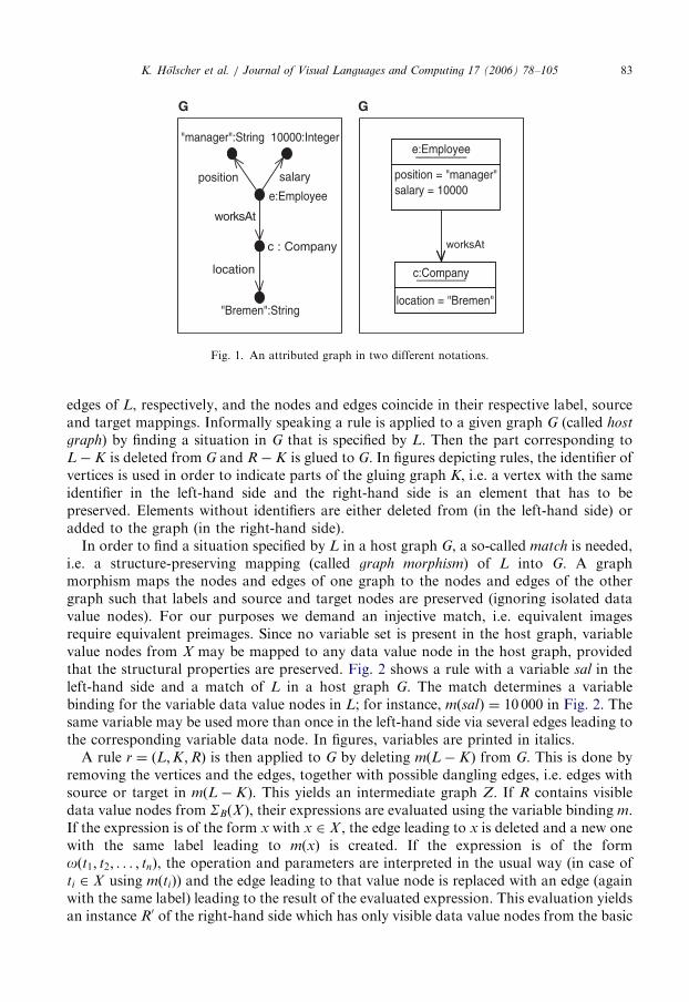
Fig. 14 shows a part of the initial system state of the drive-through example as objectdiagram instantiating the system state metamodel. Typically, system states in this notationare very large and difficult to handle for human beings. Therefore, a tool like the onepresented in Section 6.5 would depict a system state in a more comprehensible way, e.g. byhiding class, attribute and operation vertices as it is usually done with object diagrams. Thegraph transformation rules, however, work on this complex structure.
Due to the complexity of the graph, Fig. 14 shows only an excerpt of it. In the upper left,you can see an Operation vertex that represents the use case startDriveThrough. Theobjects d, c1 and c3 represent a drive-through resp. two clients (the other two clients arenot shown). The dashed arrows just indicate the relations of the objects, abstracting fromthe links and link ends that actually constitute these relations.
ARTICLE IN PRESS
sig = "serve()"
role = "meal"
: Operation
sig="startDriveThrough"
: Operation : Class : Operation
name = "DriveThrough" sig = "start()"
: AssociationEndd:Object
: Association : AssociationEnd
role = "driveThrough" name = "ToServe"
: Class
name = "Meal"
: Attribute
name = "name"type = "String"
c1: Object c3 : Object
: State : Operation : Class : State : State
name = "waiting" sig = "pay()" name = "Client" name = "waiting"name = "idle"
Fig. 14. Start system state for the drive-through example.
K. Holscher et al. / Journal of Visual Languages and Computing 17 (2006) 78–10596
During a system run, the system state is modified by graph transformation rules.Basically we need two kinds of rules: rules that depend on the given model and rules thatdo not, i.e., predefined rules. The following two subsections discuss these rules and how toconstruct them.
6.2. Rules depending on the model
The initial system state does not contain any processes, i.e., there is no operation that iscalled and waiting to be executed. This is what the use cases are needed for: for every usecase we construct a rule that adds a ComplexProcess vertex with local variables forholding the arguments where necessary.Fig. 15 shows the rule for the use case startDriveThrough. The rule creates a new
ComplexProcess connected to the Operation with the name startDriveThrough. Thestatus is set to waiting and the sequence number is set to 0 (because this process is notcreated by a message from an interaction diagram).With this kind of rule, we are now able to add processes to the system state in order to
actually start a system run. Next we need rules that handle these processes, i.e., change thesystem state according to the semantics specified in the interaction diagrams. For everyoperation specified by an interaction diagram, we construct a set of rules. This is done forevery operation no matter whether it belongs to a class or to a use case.A user-defined operation calls several other operations. An interaction diagram specifies
which other operations are called and in which order this has to be done. So an interactiondiagram contains messages that are sent between classifier roles in a specific order. Eachmessage represents the call of either a user-defined operation (of a class) or it represents thecall of a predefined operation (like setting an attribute value). Every sent messagecorresponds to the creation of a new process vertex.

ARTICLE IN PRESS
L R
o : Operation o : Operation
sig = "startDriveThrough()"
: ComplexProcess
sig = "startDriveThrough()"status = #waitingseqNo = 0
Fig. 15. Rule for creating a use case process.
p1 : ComplexProcess
status = #active
p1 : ComplexProcess
status = #activesig = "serve()" sig = "serve()"
L R
c : Class c : Class
name = "DriveThrough" name = "DriveThrough"
o : Object o : Object
activator activator
op : Operation op : Operation
p2 : LinkProcess p2 : LinkProcess
seqNo = "1.2"status = #finished
seqNo = "1.2"status = #finished
Fig. 16. Sending a message: step 1.
K. Holscher et al. / Journal of Visual Languages and Computing 17 (2006) 78–105 97
As an example we discuss the transformation unit that is necessary to handle the sendingof the message 1.3 of the interaction diagram for DriveThrough::serve() as depicted inFig. 9.
The message 1.3 is sent during the execution of the operation 1:serve of classDriveThrough. Therefore the new process vertex should only be created if there actually isa process (p1) of this operation (op) running on an object (o) of the desired class (c). Thisprocess represents the activator message of the message that corresponds to the processvertex to be created. This activator process vertex is marked with a loop for further ruleapplication. Since in this case the regarded message is not the first one sent by the activatormessage, the status of the activator process vertex has to be #active. Furthermore theexecution of the operation 1.2 should have been finished, thus the status of thecorresponding process vertex (p2)must be finished. The first rule r1 depicted in Fig. 16does exactly that.
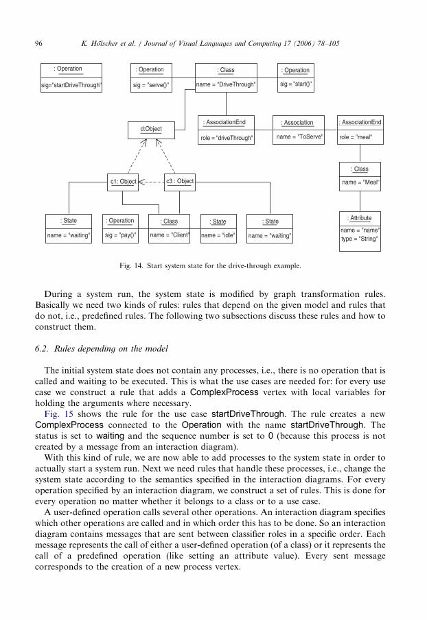
The second rule r2 creates a waiting process. This can be regarded as actually sendingthe message (see Fig. 17). The considered message in our example is sent to an object
ARTICLE IN PRESS
name = "meal"type = Mealvalue = ml
seqNo = "1.3"status = #waitingattributeName = "name"value = self.first.order.meal
name = "meal"
L R
c : Class
name = "Meal"
v : LocalVar
type = Mealvalue = ml
m : Object
p : ComplexProcess
v : LocalVar
p : ComplexProcess activator
c : Class
name = "Meal"
m : Object
: SetAttributeProcess
Fig. 17. Sending a message: step 2.
K. Holscher et al. / Journal of Visual Languages and Computing 17 (2006) 78–10598
stored in a local variable meal as indicated by the stereotype� local� and the role namemeal. In order to attach the new waiting process vertex to the correct object vertex,the left-hand side of the rule demands the presence of the LocalVar vertex attached to theactivator process vertex. This LocalVar vertex has the value Meal which refers to theObject vertex connected to the class vertex with the name Meal. The new process vertexwith status #waiting will be connected to that object vertex and its activator process vertex.Its other attributes are set according to the collaboration diagram. In particular, the valueis set to an OCL expression that is evaluated while applying the rule. In addition, the ruleremoves the loop from the activator process. The two rules have to be applied one afterthe other, thus the control condition of the transformation unit is r1;r2, meaning that firstthe rule r1 and after it rule r2 has to be applied.In general, there are a lot of circumstances to consider when constructing such a
transformation unit for sending a message. After having shown the concrete example, wewill only outline some details not covered by the example.
�
When a complex process is created instead of an atomic one, it has to be connected tothe correct Operation vertex. This is the reason why two rules are needed in general,otherwise there would be two Operation vertices in one rule that possibly represent thesame operation. Because we use injective matching, this would be impossible. � Asynchronous predecessors are represented by processes with no specified status in therule, i.e., an asynchronous predecessor does not have to be finished.
� Parallel messages are sent by creating corresponding processes at the same time in onerule.
� If the message to be sent is the message that starts the execution of a waiting process andthis execution is allowed only in certain states according to a statechart diagram, thenthe rule must only be applicable with a match containing a receiver object in the correctstate. The rule then disconnects the state from the object, which is then ‘‘between’’ twostates, and connects the next state to the new process. The object obtains its new state byanother rule when the process has finished.

ARTICLE IN PRESSK. Holscher et al. / Journal of Visual Languages and Computing 17 (2006) 78–105 99
�
If a message is sent via an association role without stereotype, a process is created andconnected to an arbitrary object (of the specified class) that is linked to the sendingobject (by a link of the specified association). Thus, the rule includes links, associations,link ends, etc. In addition, the rule creates a new local variable that stores the chosenobject, in case other messages are sent via the same association role.6.3. Predefined rules
Predefined messages do not call a user-defined operation but rather a predefinedoperation. There are messages for creating an object of a specific class, destroying anobject, connecting objects with a link of a given association, unlinking objects, setting anattribute value, setting a local variable value, and returning a result. Corresponding tothese messages there are atomic processes that are not associated with an operation butinstead with other information needed for the task. These atomic processes have alreadybeen shown in Fig. 13. The rules that handle these processes are also predefined, i.e., theyare independent from the user model.
There is a predefined rule or even transformation unit for each kind of atomic process.In addition to these, there are rules for collecting garbage. These rules remove finishedprocesses that are no longer needed as preconditions for other processes, and localvariables that are no longer attached to a process vertex. These rules are applicablewhenever such garbage exists in the system state.
In the following, we will present the transformation unit for handling a link process inmore detail.
A LinkProcess has several local variables, each of them indicating the object that issupposed to play a certain role in the link that shall be created. The followingtransformation unit manages to create and connect a Link vertex and LinkEnd vertices thatconnect the objects as requested.
link
rules:
createLink (Fig. 18) createLinkEnds (Fig. 19) finishLinking (Fig. 20)cond:
createLink; createLinkEnds!; finishLinkingTo execute a LinkProcess, the rule createLink is first applied to create a Link vertex witha flag. This new vertex is connected to the association indicated by assocName. This rulealso changes the status of the process to #active. Then, the rule createLinkEnds is appliedas long as possible to create LinkEnd vertices for all objects that are to be linked and toconnect these vertices. The NAC ensures that only one link end is created per associationend. This rule is supposed to attach new LinkEnd vertices only to the Link vertex that wascreated earlier in the application of this transformation unit, which is ensured by the flag.The flag is removed and the process is finished by the rule finishLinking (see Figs. 18–20).
In general the use of transformation units is employed in order to encapsulatefunctionality into transactions. This is due to the fact that certain rules cannot change thesystem state in one step. Since the intermediate graphs are of no interest (especially since

ARTICLE IN PRESSK. Holscher et al. / Journal of Visual Languages and Computing 17 (2006) 78–105100
the graph transformation background of the actual system state run is hidden from themodeler) they are thus neither visible nor accessible to the modeler. The information fromthe model is not reflected in the structure of the control conditions. Therefore informationfrom the model (e.g. the order of message calls) is still needed in the rules (e.g. sequencenumber).
6.4. Inheritance
In a system state an object has attribute values that are stored in AttributeLink verticesfor all attributes that are declared in its class as well as in classes it inherits. The creation ofthe initial system ensures this, and the transformation unit that handles the creation of anew object also respects this fact. Therefore, a class inherits the attributes of itssuperclasses. Associations are implicitly inherited by the construction of the transforma-tion unit that realizes a Link operation (for more details cf. [7]). An important property of
status = #waiting
L R
as : Association
name = an status = #activeassocName = an
name = an
p : LinkProcess p : LinkProcess
assocName = an
as : Association
: Link
Fig. 18. Rule createLink.
L R
name = yvalue = o
name = yvalue = o
name = y
l : Link
name = y
N
p : LinkProcess p : LinkProcess
status = #active status = #active
v : LocalVar v : LocalVar
ae : AssociationEnd ae : AssociationEndae : AssociationEnd
o : Object o : Object
as : Association
l : Link : LinkEnd: LinkEnd
l : Link
as : Association
Fig. 19. Rule createLinkEnds.

ARTICLE IN PRESS
L R
p : LinkProcess p : LinkProcess
status = #active
l : Link l : Link
status = #finished
Fig. 20. Rule finishLinking.
K. Holscher et al. / Journal of Visual Languages and Computing 17 (2006) 78–105 101
object-oriented systems that is supported by our approach is subtype polymorphism. Herean operation may be performed differently in different classes all of which have a commonsuperclass with said operation. In the context of our approach this happens whenever amessage is sent to a classifier role associated with a class that has subclasses which overridethe called operation. In this case either the operation of the superclass or one of theoverriding operations is called, depending on the class of the object that actually receivesthe message. We only allow to override an operation with another operation that hasexactly the same signature (called invariant overriding (cf. e.g. [39]) in order to avoid typingproblems. Such an overridden method has to be specified in its own interaction diagram.
This is possible, since an Operation vertex is not only connected to the one class thatdeclares it, but also to all of its subclasses that do not override it.
6.5. Implementation
Currently a prototype for the concepts discussed in this paper is being implemented. Thegoal of this prototype is to visualize the evolution of the system state. When provided witha model, the prototype automatically generates the graph transformation rules and theinitial system state graph. A graphical user interface then permits the user to view theevolution of the system state step by step and to examine the current state by querying itusing OCL.
For this reason the prototype must be able to perform graph transformations as well asto evaluate OCL expressions. Instead of implementing a new tool for these purposes, wechose to combine two well established tools. The graph transformation part is done byAGG [40] and the evaluation of OCL expressions is performed by the USE tool [41]. Anobvious choice for the tool implementation would have been the Fujaba tool [22], whichalready couples graph transformation and UML. But since the UML part has to behandled by the USE tool anyway (in order to evaluate OCL expressions), any graphtransformation engine capable of applying the rules generated by our approach suffices.Since the developers of the prototype are very familiar with AGG and its API, it has beenthe preferred choice as underlying graph transformation engine.
The prototype (hence UGT—UML to Graph Transformation) reads a USE specifica-tion of a UML model that is compatible with our approach. It then generates the set ofgraph transformation rules according to the ideas presented in this paper. Additionally, theinitial host graph is constructed from the object diagram the modeler provides. The GUI ofUGT then displays this initial graph and the use case names as specified in the model. The

ARTICLE IN PRESSK. Holscher et al. / Journal of Visual Languages and Computing 17 (2006) 78–105102
user may now select a use case to be executed. In this case, the rule that starts the executionof this use case is applied to the host graph. Now the user may click the step button andthus derive a next step in the system state evolution. Internally UGT calculates the nextstep by randomly choosing one of the rules that are applicable and letting AGG apply it.This may be done until no further rule is applicable. If this is the case, the use case iscompletely finished. As well as letting the system decide upon the next step, the user maycontrol the flow of execution. Imagine a state with two processes in status waiting or activethat can both be executed in the next step. In this case the user may decide what process isexecuted next by simply double-clicking it. If the process is specified to expect parameters,the user is prompted with an input field and forced to provide the necessary parameters.Fig. 21 shows a screenshot of UGT in action. A system state is displayed with three clientsvisiting a drive-through, each of them with a submitted order. The user chose the use casestartDriveThrough to be started, which resulted in the corresponding process being addedto the system state.By executing the system state step by step, the user can gain insight into the modeled
system. Furthermore, UGT allows the evaluation of OCL expressions at any step in thesystem state. The OCL evaluation window displaying an OCL query and its evaluatedresult can be seen in the lower part of Fig. 21. Due to this feature, it is possible to checkwhether invariants hold during the execution of operations or even complete use cases.Note that UGT completely hides the graph transformation basis of this approach from theuser. They do not need to know about the rule generation, or the fact that graphtransformation is used to derive the next step of the system state.
Fig. 21. Screenshot of UGT.
ARTICLE IN PRESSK. Holscher et al. / Journal of Visual Languages and Computing 17 (2006) 78–105 103
7. Conclusion and future work
We have presented a conceptual approach for defining a semantics for UML based onthe translation of a given UML model into a graph transformation system. Todemonstrate our approach an example model comprising several UML diagrams hasbeen introduced. Next we have described our idea of a system state by means of ametamodel followed by a discussion of the translation of a given model into model-depending and predefined graph transformation rules by example. Finally the basicconcepts of the prototypic software implementing this approach have been addressed. Theprototype translates a given UML model into a graph transformation system and allows tomonitor the evolution of the system state step by step.
The next goal is to complete the prototype implementation and to further enhance itsGUI. As the approach and the tool are suitable for early stages of the softwaredevelopment process, it might become impractical when using large and very detailedmodels. In this case the aforementioned GUI should allow the user to choose differentviews on the system run, like e.g. hiding objects and their details that are of no interest in acertain situation.
An interesting topic would be the integration of further diagram types like activitydiagrams into our approach. We will also investigate whether and how the diagramsalready covered can be extended with yet missing UML features. These include compositestates and concurrent ones in statechart diagrams and � include� and � extend�relationships between use cases.
It may also be worth investigating whether a set of elementary templates can be providedfor the rules that depend on the model. Currently every rule has to be generated fromscratch for every model. Rule templates would provide a better maintainability in the sensethat central concepts could be changed in one place instead of different rules.
Case studies will provide feedback on the practicability of the approach and tool. Inparticular, more insight is needed into the process of asserting properties of UML modelson the basis of our approach, for instance, based on transformation invariants. In this wayour approach will automatically benefit from future results in the field of graphtransformation.
References
[1] OMG, OMG Unified Modeling Language Specification, Version 1.5, March 2003, Object Management
Group, Inc., Framingham, MA, ohttp://www.omg.org4, 2003.
[2] M. Richters, A precise approach to validating UML models and OCL constraints, Ph.D. Thesis, Universitat
Bremen, Logos Verlag, Berlin, BISS Monographs, No. 14, 2002.
[3] Boldsoft, Rational Software Corporation, and IONA, Response to the UML 2.0 OCL RfP (ad/2000-09-03),
January 2003. ohttp://www.klasse.nl/ocl/ocl-subm.html4.
[4] G. Rozenberg (Ed.), Handbook of Graph Grammars and Computing by Graph Transformation,
Foundations, vol. 1, World Scientific, Singapore, 1997.
[5] H. Ehrig, G. Engels, H.-J. Kreowski, G. Rozenberg (Eds.), Handbook of Graph Grammars and Computing
by Graph Transformation, Applications, Languages and Tools, vol. 2, World Scientific, Singapore, 1999.
[6] H. Ehrig, H.-J. Kreowski, U. Montanari, G. Rozenberg (Eds.), Handbook of Graph Grammars and
Computing by Graph Transformation, Concurrency, Parallelism, and Distribution, vol. 3, World Scientific,
Singapore, 1999.
[7] P. Ziemann, An integrated operational semantics for a UML core based on graph transformation, Ph.D.
Thesis, University of Bremen, 2005.

ARTICLE IN PRESSK. Holscher et al. / Journal of Visual Languages and Computing 17 (2006) 78–105104
[8] S.-K. Kim, D.A. Carrington, An integrated framework with UML and Object-Z for developing a precise
specification: the light control case study, in: 7th Asia-Pacific Software Engineering Conference (APSEC
2000), 5–8 December 2000, Singapore. IEEE Computer Society, 2000, pp. 240–248.
[9] T. Clark, A. Evans, S. Kent, The metamodelling language calculus: foundation semantics for UML, in: H.
Hussmann (Ed.), Fundamental Approaches to Software Engineering, Fourth International Conference,
FASE 2001, held as Part of the Joint European Conferences on Theory and Practice of Software, ETAPS
2001, Genova, Italy, April 2–6, 2001, Proceedings, Lecture Notes in Computer Science, vol. 2029, Springer,
Berlin, 2001, pp. 17–31.
[10] A. Evans, S. Kent, Core meta-modelling semantics of UML: the pUML approach, in: R. France, B. Rumpe
(Eds.), UML’99—The Unified Modeling Language, Beyond the Standard, Second International Conference,
Fort Collins, CO, USA, October 28–30, 1999, Proceedings, Lecture Notes in Computer Science, vol. 1723,
Springer, Berlin, 1999, pp. 140–155.
[11] R.B. France, A. Evans, K. Lano, B. Rumpe, The UML as a formal modeling notation, Computer Standards
and Interfaces 19 (7) (1998) 325–334.
[12] H. Storrle, Semantics and verification of data flow in UML 2.0 activities, in: M. Minas (Ed.), Proceedings of
the Workshop on Visual Languages and Formal Methods (VLFM 2004), Electronic Notes in Theoretical
Computer Science, vol. 127(4), Elsevier, Amsterdam, 2005, pp. 35–52.
[13] R. Breu, U. Hinkel, C. Hofmann, C. Klein, B. Paech, B. Rumpe, V. Thurner, Towards a formalization of the
Unified Modeling Language, in: M. Aksit, S. Matsuoka (Eds.), ECOOP’97—Object-Oriented Programming,
11th European Conference, Lecture Notes in Computer Science, vol. 1241, Springer, Berlin, 1997,
pp. 344–366.
[14] R. Eshuis, R. Wieringa, A real-time execution semantics for UML activity diagrams, in: H. Hussmann (Ed.),
Fundamental Approaches to Software Engineering, Fourth International Conference, FASE 2001, held as
Part of the Joint European Conferences on Theory and Practice of Software, ETAPS 2001, Genova, Italy,
April 2–6, 2001, Proceedings, Lecture Notes in Computer Science, vol. 2029, Springer, Berlin, 2001,
pp. 76–90.
[15] R. Wieringa, Formalizing the UML in a systems engineering approach, in: H. Kilov, B. Rumpe (Eds.),
Proceedings Second ECOOPWorkshop on Precise Behavioral Semantics (with an Emphasis on OO Business
Specifications), Technische Universitat Munchen, TUM-I9813, 1998, pp. 254–266.
[16] L. Starr, Executable Uml: How to Build Class Models, Prentice Hall PTR, Upper Saddle River, NJ, USA,
2001 (Foreword by Stephen J. Mellor).
[17] S. Kuske, M. Gogolla, R. Kollmann, H.-J. Kreowski, An integrated semantics for UML class, object, and
state diagrams based on graph transformation, in: M. Butler, K. Sere (Eds.), Third International Conference
on Integrated Formal Methods (IFM’02), Lecture Notes in Computer Science, vol. 2335, Springer, Berlin,
2002, pp. 11–28.
[18] M. Gogolla, P. Ziemann, S. Kuske, Towards an integrated graph based semantics for UML, in: Graph
Transformation and Visual Modeling Techniques (GT-VMT 2002), ENTCS, vol. 72, 2003.
[19] R. Heckel, S. Sauer, Strengthening uml collaboration diagrams by state transformations, in: H. Hussmann
(Ed.), Fundamental Approaches to Software Engineering, Fourth International Conference, FASE 2001,
held as Part of the Joint European Conferences on Theory and Practice of Software, ETAPS 2001, Genova,
Italy, April 2–6, 2001, Proceedings, Lecture Notes in Computer Science, vol. 2029, Springer, Berlin, 2001,
pp. 109–123.
[20] S. Kuske, A formal semantics of uml state machines based on structured graph transformation, in: M.
Gogolla, C. Kobryn (Eds.), UML 2001—The Unified Modeling Language, Modeling Languages, Concepts,
and Tools, Lecture Notes in Computer Science, vol. 2185, 2001, pp. 241–256.
[21] D. Varro, A formal semantics of UML statecharts by model transition systems, in: A. Corradini, H. Ehrig,
H.-J. Kreowski, G. Rozenberg (Eds.), Graph Transformation, First International Conference, ICGT 2002,
Barcelona, Spain, October 2002, Proceedings, Lecture Notes in Computer Science, vol. 2505, Springer,
Berlin, 2002, pp. 378–392.
[22] T. Fischer, J. Niere, L. Torunski, A. Zundorf, Story diagrams: a new graph transformation language based
on UML and Java, in: H. Ehrig, G. Engels, H.-J. Kreowski, G. Rozenberg (Eds.), Proceedings of the Theory
and Application to Graph Transformations (TAGT’98), Paderborn, November, 1998, Lecture Notes in
Computer Science, vol. 1764, Springer, Berlin, 1998.
[23] G. Engels, R. Heckel, J.M. Kuster, L. Groenewegen, Consistency-preserving model evolution through
transformations, in: J.-M. Jezequel, H. Hussmann, S. Cook (Eds.), UML 2002—The Unified Modeling
Language, Model Engineering, Languages, Concepts, and Tools, Fifth International Conference, Dresden,

ARTICLE IN PRESSK. Holscher et al. / Journal of Visual Languages and Computing 17 (2006) 78–105 105
Germany, September/October 2002, Proceedings, Lecture Notes in Computer Science, vol. 2460, Springer,
Berlin, 2002, pp. 212–226.
[24] A. Schurr, A.J. Winter, UML Packages for PROgrammed Graph REwriting Systems, in: H. Ehrig, G.
Engels, H.-J. Kreowski, G. Rozenberg (Eds.), TAGT, Lecture Notes in Computer Science, vol. 1764,
Springer, Berlin, 1998, pp. 396–409.
[25] A. Tsiolakis, H. Ehrig, Consistency analysis of UML class and sequence diagrams using attributed graph
grammars, in: H. Ehrig, G. Taentzer (Eds.), Proceedings of Joint APPLIGRAPH/GETGRATS Workshop
on Graph Transformation Systems, Berlin, March 2000, Technical Report no. 2000/2, Technical University
of Berlin.
[26] E. Borger, A. Cavarra, E. Riccobene, Modeling the dynamics of UML state machines, in: Y. Gurevich,
P.W. Kutter, M. Odersky, L. Thiele (Eds.), Abstract State Machines, Lecture Notes in Computer Science,
vol. 1912, Springer, Berlin, 2000, pp. 223–241.
[27] A. Cavarra, E. Riccobene, P. Scandurra, Integrating UML static and dynamic views and formalizing the
interaction mechanism of UML state machines, in: E. Borger, A. Gargantini, E. Riccobene (Eds.), Abstract
State Machines, Lecture Notes in Computer Science, vol. 2589, Springer, Berlin, 2003, pp. 229–243.
[28] E. Borger, A. Cavarra, E. Riccobene, An ASM semantics for UML activity diagrams, in: T. Rus (Ed.),
Proceedings of the International Conference on Algebraic Methodology and Software Technology
(AMAST’2000), Lecture Notes in Computer Science, vol. 1816, Springer, Berlin, 2000, pp. 293–308.
[29] S. Flake, W. Mueller, An ASM definition of the dynamic OCL 2.0 semantics, in: T. Baar, A. Strohmeier, A.
Moreira, S.J. Mellor (Eds.), Proceedings of the International Conference on Unified Modeling Language
(UML’2004), Lecture Notes in Computer Science, vol. 3273, Springer, Berlin, 2004, pp. 226–240.
[30] A. Cavarra, J.K. Filipe, Formalizing liveness-enriched sequence diagrams using ASMs, in: W. Zimmermann,
B. Thalheim (Eds.), Abstract State Machines, Lecture Notes in Computer Science, vol. 3052, Springer,
Berlin, 2004, pp. 62–77.
[31] W. Shen, K.J. Compton, J. Huggins, A UML validation toolset based on abstract state machines, in: ASE,
IEEE Computer Society, Silver Spring, MD, 2001, pp. 315–318.
[32] W. Shen, K.J. Compton, J. Huggins, A method of implementing UML virtual machines with some
constraints based on abstract state machines, in: APSEC, IEEE Computer Society, Silver Spring, MD, 2003,
pp. 224–232.
[33] S. Sendall, A. Strohmeier, From use cases to system operation specifications, in: A. Evans, S. Kent, B. Selic
(Eds.), UML 2000—The Unified Modeling Language, Advancing the Standard, Third International
Conference, York, UK, October 2000, Proceedings, Lecture Notes in Computer Science, vol. 1939, Springer,
Berlin, 2000, pp. 1–15.
[34] R. Heckel, J.M. Kuster, G. Taentzer, Confluence of typed attributed graph transformation systems, in: A.
Corradini, H. Ehrig, H.-J. Kreowski, G. Rozenberg (Eds.), Graph Transformation, First International
Conference, ICGT 2002, Barcelona, Spain, October 7–12, 2002, Proceedings, Lecture Notes in Computer
Science, vol. 2505, Springer, Berlin, 2002, pp. 161–176.
[35] H.-J. Kreowski, S. Kuske, Graph transformation units with interleaving semantics, Formal Aspects of
Computing 11 (6) (1999) 690–723.
[36] S. Kuske, Transformation units—a structuring principle for graph transformation systems, Ph.D. Thesis,
University of Bremen, 2000.
[37] G. Booch, J. Rumbaugh, I. Jacobson, The Unified Modeling Language User Guide, Addison-Wesley,
Reading, MA, 1998.
[38] B. Cordes, K. Holscher, H.-J. Kreowski, UML interaction diagrams: correct translation of sequence
diagrams into collaboration diagrams, in: M. Nagl, J. Pfaltz, B. Bohlen (Eds.), AGTIVE’03 Proceedings,
Lecture Notes in Computer Science, vol. 3062, Springer, 2004, pp. 275–291.
[39] M. Abadi, L. Cardelli, A Theory of Objects, Springer, Berlin, 1998.
[40] The Attributed Graph Grammar System AGG, last revision 2005. ohttp://tfs.cs.tu-berlin.de/agg4.
[41] A UML-based Specification Environment, last revision 2005. ohttp://www.db.informatik.uni-bremen.de/
projects/USE4.