Embed Size (px)
Citation preview
2IEICE TRANS. COMMUN., VOL.E103–B, NO.1 JANUARY 2020
INVITED PAPER Special Section on Internet Architecture, Applications and Operation Technologies for a Cyber-Physical System
On the Design and Implementation of IP-over-P2P Overlay VirtualPrivate Networks∗
Kensworth SUBRATIE†a), Saumitra ADITYA†, Vahid DANESHMAND†, Nonmembers,Kohei ICHIKAWA††, Member, and Renato FIGUEIREDO†, Nonmember
SUMMARY The success and scale of the Internet and its protocol IPhas spurred emergent distributed technologies such as fog/edge computingand new application models based on distributed containerized microser-vices. The Internet of Things and Connected Communities are poised tobuild on these technologies and models and to benefit from the ability tocommunicate in a peer-to-peer (P2P) fashion. Ubiquitous sensing, actuat-ing and computing implies a scale that breaks the centralized cloud comput-ing model. Challenges stemming from limited IPv4 public addresses, theneed for transport layer authentication, confidentiality and integrity becomea burden on developing new middleware and applications designed for thenetwork’s edge. One approach - not reliant on the slow adoption of IPv6- is the use of virtualized overlay networks, which abstract the complexi-ties of the underlying heterogeneous networks that span the components ofdistributed fog applications and middleware. This paper describes the evo-lution of the design and implementation of IP-over-P2P (IPOP) - from itspurist P2P inception, to a pragmatic hybrid model which is influenced byand incorporates standards. The hybrid client-server/P2P approach allowsIPOP to leverage existing robust and mature cloud infrastructure, while stillproviding the characteristics needed at the edge. IPOP is networking cyberinfrastructure that presents an overlay virtual private network which self-organizes with dynamic membership of peer nodes into a scalable structure.IPOP is resilient to partitioning, supports redundant paths within its fabric,and provides software defined programming of switching rules to utilizethese properties of its topology.key words: overlay networks, P2P, FOG, EDGE computing, SDN
1. Introduction
The Internet’s core protocol (IP) has been successful at anunprecedented scale. While the use of IPv4 identifiers andlack of security simplified the addition of devices to theInternet in its early days, they have turned into shortcom-ings as the network scales and security becomes a primaryconcern. In today’s Internet, IPv4 addresses are scarce be-cause of near-exhaustion of the 32-bit address space, andmany networks have to resort to the use of private addresses
Manuscript received May 20, 2019.Manuscript revised June 19, 2019.Manuscript publicized August 5, 2019.†The authors are with ACIS Lab, Electrical and Computer En-
gineering, University of Florida, USA.††The author is with Division of Information Science at the Nara
Institute of Science and Technology (NAIST), Ikoma-shi, 630-0192 Japan.
∗This material is based upon work supported in part by the Na-tional Science Foundation under Grants No. 1527415, 1339737,1234983 and 1550126. Any opinions, findings, and conclusionsor recommendations expressed in this material are those of the au-thor(s) and do not necessarily reflect the views of the National Sci-ence Foundation.
a) E-mail: [email protected]: 10.1587/transcom.2019CPI0001
and Network Address Translation (NAT) [1] middleboxes.Security concerns also have led to the proliferation of fire-wall middleboxes, while the need for authentication, confi-dentiality and integrity have led to transport-layer protocols(e.g. TLS [2], [3]). As a result, distributed applications thatrun across the Internet often must deal with devices with-out public IPv4 addresses that are behind various NAT andfirewall middleboxes and must create secure transport ses-sions for communication. While these issues are relativelyeasy to handle with client-server applications, they place aburden to applications where peer-to-peer communication isneeded.
Emerging distributed applications in edge/fog [4], [5]computing are poised to benefit from the ability for IoT andedge nodes to communicate in a peer-to-peer fashion. How-ever, the connectivity challenges outlined above become anincreasing burden on the development of middleware andapplications as they move from the cloud to the edge [6],including security and privacy [7]. While the subsequentIPv6 protocol offers a larger address space and built-in secu-rity features, it is still not widely deployed despite decadessince its release. An approach to address these challengesthat does not require a core change to Internet protocols isto create overlay networks [8], [9] that tunnel traffic over theexisting infrastructure. Coupled with network virtualization,overlays offer the ability to support existing middleware andapplications, while shielding them from dealing with com-plexities due to private addressing, network address transla-tion, and firewall policies.
This paper describes the design and implementationof IP-over-P2P (IPOP [10]–[15]), an overlay virtual pri-vate network that supports tunneling of layer-2 (Ethernet)and above (including IPv4) traffic across peer-to-peer tun-nels. IPOP exposes virtual network interface endpointsthat integrate with existing operating systems, automaticallymanages NAT traversal across peers with private IP ad-dresses, self-organizes scalable overlay topologies and, sup-ports encryption of peer-to-peer links, and allows software-defined programming of switching rules. IPOP provides anetwork virtualization substrate upon which geographicallydistributed IoT, edge, and cloud computing resources can belogically aggregated to facilitate the design of fog comput-ing applications. This paper describes the evolution of thedesign and open-source implementation IPOP over severaliterations of the project.
The advent of virtualization and cloud computing has
Copyright c© 2020 The Institute of Electronics, Information and Communication Engineers

SUBRATIE et al.: ON THE DESIGN AND IMPLEMENTATION OF IP-OVER-P2P OVERLAY VIRTUAL PRIVATE NETWORKS3
fundamentally changed the way in which distributed appli-cations and services are deployed and managed. With theproliferation of IoT and mobile devices, virtualized systemsakin to those offered by cloud providers are increasinglyneeded geographically near the edge of the network [4]. Ap-plications on resources at the edge can perform operationson high-volume data produced by sensors (e.g. real-timehigh-definition camera feeds) near IoT devices for latency-sensitive, bandwidth-intensive applications – a model re-ferred to as fog computing [5]. Not only is performanceimportant, but also a trustworthy network is key to guaran-tee privacy and integrity at the network layer across all par-ticipating resources (e.g. IoT, cloud VMs, and containers inedge resources [16]).
While software-defined virtual networking systems ex-ist within large-scale cloud data centers [17] - at the core ofthe Internet and under a single administrative entity - theseare not suited for future distributed applications spanningedge resources. Such fog applications are distributed acrossmultiple providers and edge networks, raising more com-plex security and privacy issues than in cloud environments[6]. Unlike within a cloud, edge virtual networks requiretraversing multiple (possibly NATed [7]) administrative en-vironments across different providers and enforcing data pri-vacy and integrity in communication. While transport-layernetwork security (e.g. TLS, DTLS) and VPN tunneling (e.g.IPSEC) technologies exist, they are not readily applicable tosystems where resource membership is dynamic, and wheremost devices are constrained by NAT/firewall middleboxes.Furthermore, the effort associated with developing or port-ing applications to enforce privacy and integrity in commu-nications comes with significant costs.
To accomplish its required functionality, a fog appli-cation requires the ability to deploy, aggregate and processdata from sensors on edge and cloud resources in a dynamicfashion. It also needs to support dynamic changes in themembership of participating devices over time, as devicesmay be mobile (e.g. video cameras in smartphones and vehi-cles). Fundamentally, the network connecting IoT, edge andcloud resources must provide trustworthy, seamless commu-nication across a dynamic, heterogeneous, mobile set of re-sources.
The current version of IPOP implements a hybridoverlay/software-defined network (SDN [18]) software thatis novel in how it supports dynamic grouping/aggregationof edge and cloud devices into a trustworthy virtual privatenetwork that leverages Online Social Network (OSN) inter-faces for self-configuration. The following sections outlinethe core concepts in the design, and the evolution of the im-plementation leading to its current form.
2. Core Abstractions and Architecture
The core abstraction exposed by IPOP to a computer systemusing it is of a virtual network. The 1st generation of the de-signed exposed the abstraction of a layer-3 (IP) virtual net-work [10]–[12], while the 3rd and 4th generations expose the
Fig. 1 IPOP’s structured P2P architecture and virtualized endpoint.Nodes are connected in successive order based on their integer node identi-fiers (e.g. A < B < C <D) to form an outer “ring”. Additionally, the overlayfeatures shortcut links (e.g. A-D) which reduce routing complexity. In eachIPOP node (e.g. C), there is a TAP device to pick/inject packets from theO/S kernel, and a user-mode IPOP application that implements the overlayvirtual network functionality.
abstraction at layer-2 (Ethernet) [13], [14]. In both cases,the abstraction is exposed through a virtual network inter-face (VNIC), such as the TAP pseudo-device available inthe Linux and Windows kernels, from which frames/packetsthat are sent and received are intercepted. IPOP nodes areimplemented as a user-space process that runs in each nodeconnected to the overlay; this process reads/writes from theTAP device, using the system call interface, as illustrated inFig. 1.
IPOP nodes form virtual links among each other, whereeach virtual link is an Internet tunnel that carries encryptedand encapsulated virtual network frames/packets through atransport protocol – typically UDP, which is more amenableto NAT traversal than TCP.
Each IPOP node in an overlay is uniquely identifiedby a node ID (e.g. A, B, ..., F) in Fig. 1. The set of vir-tual links among IPOP nodes forms a topology. While dif-ferent overlay topologies have been implemented in IPOPversions over time, a structured P2P topology has been afeature of the design since its inception. In this topology,nodes form a logical ring, with successor links ordered bytheir node IDs, and shortcut links across the ring, followinga structured P2P algorithm for topology construction andidentifier-based routing such as Chord [19] or Symphony[20].
3. Fully Decentralized P2P Design
The 1st generation of IPOP [10] was fully decentralized,following a structured P2P design using the Brunet [21] li-brary and a Symphony-based protocol. Two key motivationsfor this approach were to avoid any external dependences,and any single point of failure. Each node implemented thefunctionality to 1) discover other nodes by means of a peerlist file, 2) bootstrapping by contacting nodes in the peer listand using them to send messages to the joining peer’s left
4IEICE TRANS. COMMUN., VOL.E103–B, NO.1 JANUARY 2020
and right neighbors, 3) providing support for discovery of anode’s public IP:port endpoint, and 4) forwarding messagesaccording to a greedy routing algorithm.
This implementation provided a layer-3 virtual networkfor the IPv4 protocol. There was no encryption, and no au-thentication of nodes into the overlay. IP addresses wereassigned to nodes by leveraging a Distributed Hash Table(DHT [19]) key/value store which was also implemented byIPOP nodes. The DHT used a compound key, comprising ofa virtual network namespace and a virtual IP address to mapthe node’s IPOP ID. This allowed multiple virtual networksto share a single overlay without collision of private subnets.IPOP nodes also included an implementation of a user-levelDHCP server that handed out IP addresses by randomly as-signing an address within a declared virtual network names-pace and inserting the mapping into the DHT [22].
While this implementation proved to be useful in manyscenarios, and resilient to failures and churn, it had severalshortcomings. First, the monolithic design led to a com-plex node that implemented several modules for discoveryand bootstrapping, DHT, overlay routing, NAT traversal, IPaddress assignment/mapping, as well as virtual network in-terface bindings. Second, the use of a monolithic designimplemented as an application written in C# made it diffi-cult to incorporate standards and functionality in librarieswritten for different languages into a single process. In par-ticular, the ICE, STUN, and TURN [23], [24] protocols forNAT traversal were not supported, as well as transport-layersecurity. Third, the design did not provide a mechanism toauthenticate peers into the overlay. Fourth, rules for packetforwarding and header manipulation, such as IP mapping,were implemented in the monolithic node, preventing theability to change them without significant code investment.These shortcomings were progressively addressed in sub-sequent implementations of IPOP, as described in the nextsections.
4. Decoupling Endpoint Discovery from Overlay
To tackle the complexities of overlay membership, endpointdiscovery and bootstrapping links - which stem from its ini-tial design - the 2nd generation of IPOP [12] introduced asignaling process reliant on online social networks (OSN).Each host in an overlay is represented and identified by anOSN Identity (ONSI) which exists on an OSN server. TheONSI maintains the notion of a social network (i.e., its pri-vate roster of friends) which corresponds to the peer hoststhat participate in its overlay.
By using an XMPP [25] compliant instant messagingservice, issues of overlay membership and credentialing arehandled externally by a service that follows a widely usedstandard, and that supports the authentication of user ac-counts and the establishment of trust relationships betweenusers. Additionally, a published service eliminates the needto have prior knowledge of online nodes in order to join theoverlay. Instant messaging provides the facility to exchangebootstrapping data that is used in support of other estab-
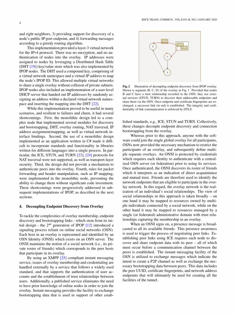
Fig. 2 Illustration of decoupling endpoint discovery from IPOP overlay.Shown is segment (B, C, D) of the overlay in Fig. 1. Provided that nodesB and C have a trust relationship recorded in the OSN, they use exter-nal services (STUN, TURN) to discover their addressable endpoints andshare them via the OSN. Once endpoint and certificate fingerprints are ex-changed, a successor link (in red) is established. The integrity and confi-dentiality of link communication is enforced by DTLS.
lished standards, e.g., ICE, STUN and TURN. Collectively,these changes decouple endpoint discovery and connectionbootstrapping from the overlay.
Whereas prior to this approach, anyone with the soft-ware could join the single global overlay for all participants,OSNs now provided the necessary mechanism to restrict theparticipants of an overlay, and subsequently define multi-ple separate overlays. An ONSI is protected by credentialswhich requires each identity to authenticate with a central-ized OSN server (or federation) prior to using its services.Once authenticated, the OSNI discovers its roster of friendswhich it interprets as an indication of direct acquaintanceand mutual trust. Friends are therefore used to identify thenetwork endpoints that are eligible to participate in the over-lay network. In this regard, the overlay network is the real-ization of an individual’s social relationships. The view ofsocial relationships in this approach is taken broadly – onone hand it may be mapped to resources owned by multi-ple individuals connected by a social network, while on theother hand it may be mapped to resources managed by asingle (or federated) administrative domain with trust rela-tionships capturing the membership in an overlay.
When an OSNI signs on, a presence message is broad-casted to all its available friends. This presence awarenessis used to trigger the process of negotiating peer links. Es-tablishing peer links using ICE requires each node to dis-cover and share endpoint data with its peer – all of whichmust occur before a communication channel between thepeers is established. The instant messaging facility of theOSN is utilized to exchange messages which indicate theintent to create a P2P channel as well as exchange the nec-essary bootstrapping data between peers. This data includesthe peer UUID, certificate fingerprints, and network addressendpoints that will ultimately be used for creating all thefacilities of the tunnel.

SUBRATIE et al.: ON THE DESIGN AND IMPLEMENTATION OF IP-OVER-P2P OVERLAY VIRTUAL PRIVATE NETWORKS5
5. Decoupling Control from Datapath
Another enhancement introduced in 2nd generation IPOPwas the separation of concerns between control and data-path. Rather than the monolithic process of its initial imple-mentation, starting in [12], IPOP adopted an SDN-inspiredmodular design of controller and data-path components.
The IPOP datapath (Tincan) builds on WebRTC [26],[27] to create its communication links. WebRTC is an openstandard and industry effort to enable direct, real-time mediacommunication between browsers. Tincan utilizes the We-bRTC native C++ libraries for data channels which consti-tutes the virtual link between peers. These virtual links useeither direct, reflexive, or relay connections. Direct connec-tion occurs when two nodes have routable endpoints usingtheir local IP address (e.g. within a LAN); reflexive connec-tions occurs when nodes are behind cone-style NATs that areamenable to STUN-based traversal; relay connections oc-curs when an intermediary server is necessary to exchangemessages. Tincan also handles the IO interaction betweenthe VNIC and the virtual link. Ethernet frames read fromthe VNIC are encrypted using DTLS, encapsulated as thepayload of an IP datagram and transmitted on the link. Con-versely, incoming messages are stripped of the UDP head-ers, decrypted and written to the VNIC.
The 3rd generation IPOP Controller uses a modularframework which separates the application framework fromthe modules which implement specific functionalities [14].The controller framework loads and initializes a parameter-ized list of modules at startup, providing an asynchronoustask-based messaging service for inter-module communica-tions. The Controller Brokered Task (CBT) abstraction isused for this purpose; it is a self-contained structure thatfully describes the task over its lifetime, including all thedetails pertaining to its request and response. A CBT is cre-ated by a module, submitted to the framework, and deliveredto the recipient modules work queue. When the requestedtask is completed, the CBT is returned to the initiator viathe framework.
A control module is a component with an application-specific role within the IPOP Controller. By implementing aframework defined interface, modules can be loaded and ini-tialized, sent CBTs for processing, and invoked at periodicintervals. Modules can be created for any purpose to extendthe capabilities of the IPOP Controller. A few core mod-ules include signaling, link negotiation and creation, topol-ogy definition, and status reporting.
The signaling module leverages XMPP to advertisepresence, indicate intent, and exchange connection boot-strap data. At sign-on, and on periodic intervals, a nodebroadcasts a presence message to all peers on its friendshiproster indicating its availability for a communication chan-nel. This module services requests that require peer com-munication over the XMMP band.
The link management module manages tunnels be-tween peers, mirroring the notion of the link layer between
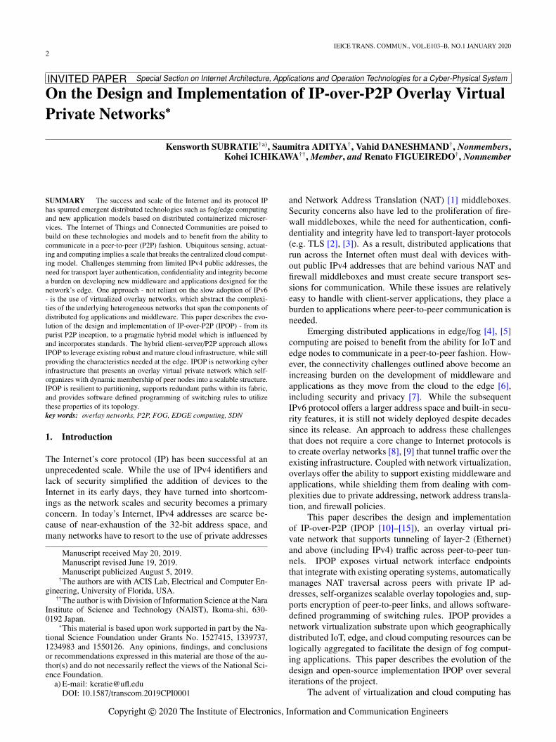
Fig. 3 Decoupling of the IPOP node design into control and data-pathmodules. The data-path module is responsible for packet capture/injection,as well as for the setup and maintenance of peer-to-peer private tunnelsthrough which virtual network traffic flows. The control module is respon-sible for signaling, link management, and topology management, amongother functions. These modules are implemented as separate processes,written in separate languages (currently, a Python controller and C++ dat-apath) that execute in the same node and communicate via a localhost net-work API.
two networked devices. It creates, maintains and destroystunnels as a service to other modules and utilizes the signalmodule to indicate the intent to create a link as well as ex-changing the link bootstrapping data. Additionally, it tracksthe VNIC and link for each tunnel and instructs the data-path to create them – coordinating as an intermediary theCAS exchange handshake between the local and peer dataplanes.
The topology module determines the placement of tun-nels and their duration. It utilizes the link managementservices for the creation of individual tunnels and orches-trates the local node’s participation in the construction ofthe global structure. The 4th generation implementation isa structured P2P topology based on a successor ring withshortcut paths.
Monitoring of the overlay state is accomplished by co-operative work among the reporting module and the othercontroller. Participating modules periodically submit theirrespective state to the reporting module which aggregatesthe data into a node wide representation. The node data issent to a central collector webservice which aggregates nodedata into a global view encompassing all the reported over-lays and their respective nodes.
6. Software-Defined Switching
In its 4th generation, IPOP moved from a layer-3 to a layer-2virtual network and implemented an OpenFlow SDN con-troller. This allows IPOP to support broadcast/multicast pro-tocols other than IP (e.g. ARP), relocatable IP addresses,and a wider variety of applications. Furthermore, support-ing the OpenFlow API and SDN-based software switches,opens the virtualized overlay to a variety of possible net-working implementations.
IPOP virtualizes a layer 2 broadcast domain via the lo-
6IEICE TRANS. COMMUN., VOL.E103–B, NO.1 JANUARY 2020
cal system TAP device or an OpenFlow software bridge, andby tunneling Ethernet frames. The ring structure with short-cut links provides multiple redundant paths between net-work switches in the overlay. If utilized, these links providealternate paths to avoid IO bottlenecks and resilience againstlink failures. However, typical Ethernet switching does notaccommodate a topology with cycles, and network failurefrom broadcast storms occurs if cycles are not disabled. Ap-proaches such as Spanning Tree Protocol (STP) are used inlocal-area Ethernet networks to selectively disable links andconstruct a cycle-free spanning tree. Unfortunately, this ap-proach ignores functional links that could otherwise be usedas alternative paths between pairs of communicating hosts.To address the issues stemming from cyclic paths while stillretaining the functional benefits of multiple links, an Open-Flow compliant switching protocol, called Bounded Flood-ing, has been designed and implemented for structured P2Ptopologies in IPOP.
Each IPOP node instantiate two controller components:an IPOP controller and an OpenFlow controller module –producing a decentralized system. The IPOP controllerbuilds and maintains the topology while the OpenFlow con-troller programs the switching rules. The OpenFlow con-troller functionality is topology dependent and relies onstructural information queried from the IPOP controller,such as the node’s adjacency list. It is designed to be scal-able from overlays with two nodes to thousands of nodes.
The IPOP topology is a ring of successors with identi-fiers increasing clockwise and arcs of shortcut links. Eachswitching node running IPOP is assigned a UUID, and eachnode bears the responsibility of identifying its closest neigh-bor (next larger UUID) and building a successor link be-tween them; a node may select more than one successorfor resilience against interruptions from churn. This pro-cess continues with each node until the ring is complete.The number of nodes in the overlay are proportional to theaverage number of switching hops to deliver frames in theoverlay and subsequently is used as a measure of the per-ceived latency in communication. While a complete net-work would provide constant switching cost, it is infeasiblefor overlays with more than tens of nodes. For an overlaywith n nodes, each new node adds (n − 1) edges for a totaln(n−1)/2 edges. As each tunnel incurs an ongoing commu-nication cost over its lifetime this approach does not scale asmaintenance data begins to saturate the network.
Shortcut links can used to bound the average latency,and using log2 (n) links per node provides an equivalentbound [19]. To choose a suitable peer for the shortcut linksthe Symphony Long Distance Links [20] selection algo-rithm is used. The overlay is parameterized to tune the trade-offs between node degree and latency, and each node can beindependently configured.
Topology data provided by the IPOP controller is usedto distinguish between directly connected peer bridges andleaf devices, and to associate the leaf devices with their re-spective root bridge. Knowledge of a device’s root bridge isnecessary for building on demand tunnels which are a mech-
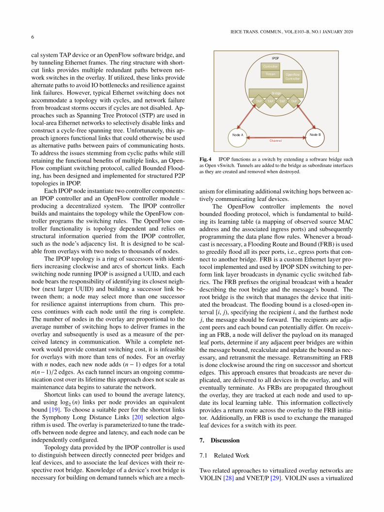
Fig. 4 IPOP functions as a switch by extending a software bridge suchas Open vSwitch. Tunnels are added to the bridge as subordinate interfacesas they are created and removed when destroyed.
anism for eliminating additional switching hops between ac-tively communicating leaf devices.
The OpenFlow controller implements the novelbounded flooding protocol, which is fundamental to build-ing its learning table (a mapping of observed source MACaddress and the associated ingress ports) and subsequentlyprogramming the data plane flow rules. Whenever a broad-cast is necessary, a Flooding Route and Bound (FRB) is usedto greedily flood all its peer ports, i.e., egress ports that con-nect to another bridge. FRB is a custom Ethernet layer pro-tocol implemented and used by IPOP SDN switching to per-form link layer broadcasts in dynamic cyclic switched fab-rics. The FRB prefixes the original broadcast with a headerdescribing the root bridge and the message’s bound. Theroot bridge is the switch that manages the device that initi-ated the broadcast. The flooding bound is a closed-open in-terval [i, j), specifying the recipient i, and the furthest nodej, the message should be forward. The recipients are adja-cent peers and each bound can potentially differ. On receiv-ing an FRB, a node will deliver the payload on its managedleaf ports, determine if any adjacent peer bridges are withinthe message bound, recalculate and update the bound as nec-essary, and retransmit the message. Retransmitting an FRBis done clockwise around the ring on successor and shortcutedges. This approach ensures that broadcasts are never du-plicated, are delivered to all devices in the overlay, and willeventually terminate. As FRBs are propagated throughoutthe overlay, they are tracked at each node and used to up-date its local learning table. This information collectivelyprovides a return route across the overlay to the FRB initia-tor. Additionally, an FRB is used to exchange the managedleaf devices for a switch with its peer.
7. Discussion
7.1 Related Work
Two related approaches to virtualized overlay networks areVIOLIN [28] and VNET/P [29]. VIOLIN uses a virtualized
SUBRATIE et al.: ON THE DESIGN AND IMPLEMENTATION OF IP-OVER-P2P OVERLAY VIRTUAL PRIVATE NETWORKS7
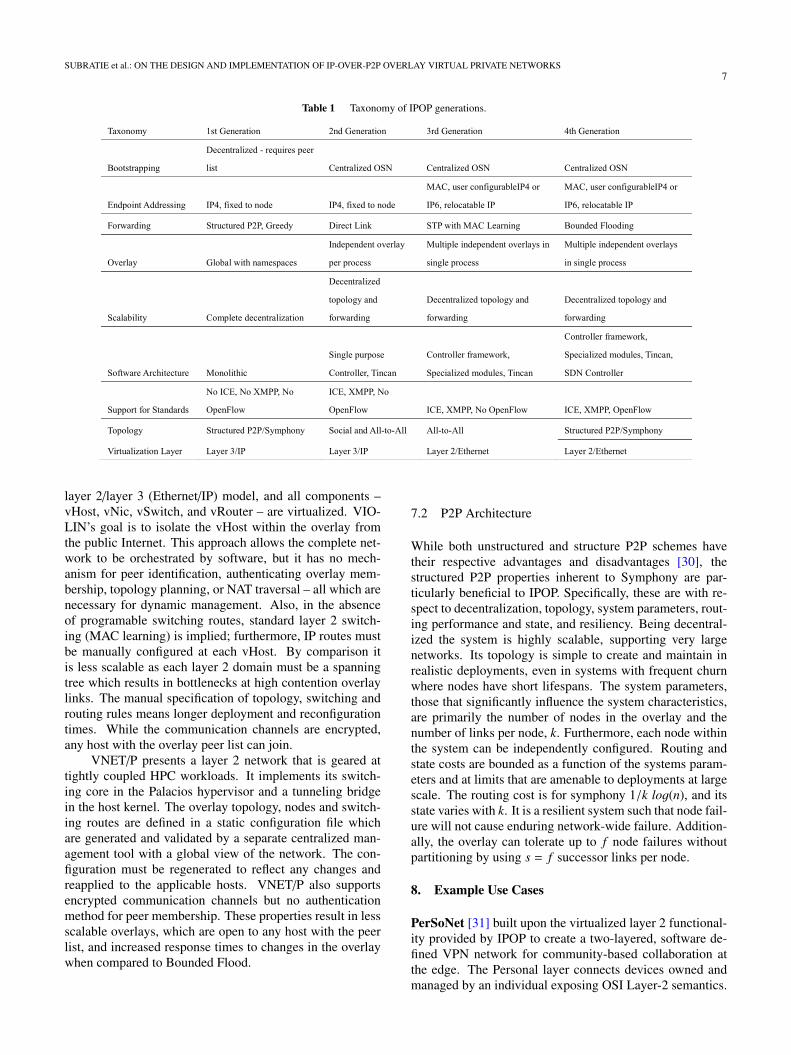
Table 1 Taxonomy of IPOP generations.
layer 2/layer 3 (Ethernet/IP) model, and all components –vHost, vNic, vSwitch, and vRouter – are virtualized. VIO-LIN’s goal is to isolate the vHost within the overlay fromthe public Internet. This approach allows the complete net-work to be orchestrated by software, but it has no mech-anism for peer identification, authenticating overlay mem-bership, topology planning, or NAT traversal – all which arenecessary for dynamic management. Also, in the absenceof programable switching routes, standard layer 2 switch-ing (MAC learning) is implied; furthermore, IP routes mustbe manually configured at each vHost. By comparison itis less scalable as each layer 2 domain must be a spanningtree which results in bottlenecks at high contention overlaylinks. The manual specification of topology, switching androuting rules means longer deployment and reconfigurationtimes. While the communication channels are encrypted,any host with the overlay peer list can join.
VNET/P presents a layer 2 network that is geared attightly coupled HPC workloads. It implements its switch-ing core in the Palacios hypervisor and a tunneling bridgein the host kernel. The overlay topology, nodes and switch-ing routes are defined in a static configuration file whichare generated and validated by a separate centralized man-agement tool with a global view of the network. The con-figuration must be regenerated to reflect any changes andreapplied to the applicable hosts. VNET/P also supportsencrypted communication channels but no authenticationmethod for peer membership. These properties result in lessscalable overlays, which are open to any host with the peerlist, and increased response times to changes in the overlaywhen compared to Bounded Flood.
7.2 P2P Architecture
While both unstructured and structure P2P schemes havetheir respective advantages and disadvantages [30], thestructured P2P properties inherent to Symphony are par-ticularly beneficial to IPOP. Specifically, these are with re-spect to decentralization, topology, system parameters, rout-ing performance and state, and resiliency. Being decentral-ized the system is highly scalable, supporting very largenetworks. Its topology is simple to create and maintain inrealistic deployments, even in systems with frequent churnwhere nodes have short lifespans. The system parameters,those that significantly influence the system characteristics,are primarily the number of nodes in the overlay and thenumber of links per node, k. Furthermore, each node withinthe system can be independently configured. Routing andstate costs are bounded as a function of the systems param-eters and at limits that are amenable to deployments at largescale. The routing cost is for symphony 1/k log(n), and itsstate varies with k. It is a resilient system such that node fail-ure will not cause enduring network-wide failure. Addition-ally, the overlay can tolerate up to f node failures withoutpartitioning by using s = f successor links per node.
8. Example Use Cases
PerSoNet [31] built upon the virtualized layer 2 functional-ity provided by IPOP to create a two-layered, software de-fined VPN network for community-based collaboration atthe edge. The Personal layer connects devices owned andmanaged by an individual exposing OSI Layer-2 semantics.
8IEICE TRANS. COMMUN., VOL.E103–B, NO.1 JANUARY 2020
Above it, connectivity among devices belonging to differentpeers is provided by interconnecting the personal networksof individuals via SDN-programmable gateways to create aCommunity layer overlay network with OSI Layer-3 seman-tics. PerSoNet abstracts the complexities involved in man-aging IP layer addressing, device name management, accesscontrol and connectivity by a combination of DNS query in-terception and processing along with reactive programmingof software defined gateways to perform address translationand switching.
GRAPLE is an inter-disciplinary collaboration be-tween computer scientists and lake modelers associated withtwo international networks, GLEON (Global Lake Ecologi-cal Observatory Network) and PRAGMA (Pacific Rim Ap-plications and Grid Middleware Assembly). The GRAPLEcollaboration’s main software product is GRAPLEr [32].While it is relatively easy to run one lake model simula-tion on a personal computer, it is more challenging to ex-ecute multiple simulations, which requires additional com-puting and human resources. To overcome this constraint,GRAPLEr, as a distributed computing system, integratesand applies the IPOP overlay virtual network to supporthigh-throughput computing, and Web service technologies.By using IPOP as a virtual network substrate, GRAPLEris able to reuse existing, unmodified software, includingthe HTCondor job scheduler, and to enable simple addi-tion of resources across the Internet to the HTCondor pool.GRAPLEr allows submission of hundreds or thousands ofGeneral Lake Model (GLM) simulations, runs these lakemodel simulations efficiently, and retrieves the model out-put.
PRAGMA Experimental Networking Testbed(PRAGMA-ENT) is an international SDN testbed that isdesigned to offer complete freedom for researchers to ac-cess network resources to develop, experiment, and evaluatenew ideas without interfering with a production network.PRAGMA-ENT connects OpenFlow-enabled switches indifferent institutions over high-speed networks and buildsa large scale OpenFlow-based network testbed. In this usecase scenario, IPOP has been used to extend the testbed witha software-defined overlay, in order to enable sites that donot have OpenFlow-enabled switches nor a direct connec-tion to the backbone of PRAGMA-ENT. Using IPOP, eachend-user can deploy an access network between their re-sources and the nearest PRAGMA-ENT endpoint. This ap-proach works effectively for those end-users who just needto connect their resources to PRAGMA-ENT temporarilyfor their experiments.
9. Conclusion
We have traced the evolution of IPOP from its P2P originsin Brunet to its current hybrid implementation, showing howspecific needs of a real-world system have driven pragmaticdesign changes at each stage. These changes allow IPOP tofill a gap in emergent technologies and seamlessly integrateexisting applications. We have also illustrated real world
systems that utilize IPOP’s capabilities, demonstrating itspractical applications.
Generation 1 virtualized a layer 3 network throughVNIC host integration and tunneling IP packets withinUDP/IP. It was a fully decentralized overlay, utilizing theBrunet library. The architecture reflected a monolithic pro-cess that incorporated all services for bootstrapping andpacket forwarding which made interoperability with openstandards difficult. The global overlay used namespace iden-tifiers and DHT store to provide scope for IP subnetting.Joining the overlay required a peer list and used overlaylinks to carry bootstrap messages, and there was no supportfor authentication or encryption.
Generation 2 introduced OSNs to decouple endpointdiscovery from the overlay and introduced a client-servermodel for bootstrapping. While no longer a pure P2P model,using a published OSN server and friendship relationshipsfacilitated independent overlays, simplified bootstrappingand enforced authentication for membership. The mono-lithic process was separated into a control and data plane andstandards such as ICE, STUN, TURN was adopted. Movingfrom the Brunet library meant losing the Symphony struc-ture; to accommodate this links were create to all friendsand IP mapping performed between them. An SDN inspiredapproach was adopted which split IPOP into controller anddata plane processes. However, the coarse granularity of thearchitectural components still left code maintenance and en-hancements challenging.
Generation 3 addressed the architectural problems byintroducing the controller application framework. The con-troller utilized modular components focused on topology,link management and signaling. Improvements to the dataplane supported multiple, concurrent, isolated layer 2 over-lays within a single process.
Generation 4 reintroduced the Symphony structuredring topology, implemented in an IPOP controller module.To provide the switching routes for the specialized topology,a Ryu/OpenFlow module implementing Bounded Flood isused. Both the algorithms for the topology and switch-ing rules were designed to be parameterized and scalableto function for networks as small as two nodes to hundredson nodes.
References
[1] P. Srisuresh and K. Egevang, “Traditional IP network address trans-lator (traditional NAT),” 2000. [Online]. Available: https://www.rfc-editor.org/info/rfc3022. [Accessed: 13-Jun-2019].
[2] E. Rescorla, “The transport layer security (TLS) protocol ver-sion 1.3,” 2018. [Online]. Available: https://www.rfc-editor.org/info/
rfc8446. [Accessed: 13-Jun-2019].[3] E. Rescorla and N. Modadugu, “Datagram transport layer se-
curity version 1.2,” 2012. [Online]. Available: https://www.rfc-editor.org/info/rfc6347. [Accessed: 13-Jun-2019].
[4] A. Yousefpour, C. Fung, T. Nguyen, K. Kadiyala, F. Jalali, A. Ni-akanlahiji, J. Kong, and J.P. Jue, “All one needs to know about fogcomputing and related edge computing paradigms: A complete sur-vey,” J. Syst. Architect., vol.98, pp.289–330, Feb. 2019.
[5] N. Bessis and C. Dobre, eds., Big Data and Internet of Things: A
SUBRATIE et al.: ON THE DESIGN AND IMPLEMENTATION OF IP-OVER-P2P OVERLAY VIRTUAL PRIVATE NETWORKS9
Roadmap for Smart Environments, vol.546, Springer InternationalPublishing, Cham, 2014.
[6] H. Chang, A. Hari, S. Mukherjee, and T.V. Lakshman, “Bringing thecloud to the edge,” 2014 IEEE Conference on Computer Communi-cations Workshops (INFOCOM WKSHPS), pp.346–351, 2014.
[7] Y. Guan, J. Shao, G. Wei, and M. Xie, “Data security and privacy infog computing,” IEEE Netw., vol.32, no.5, pp.106–111, Sept. 2018.
[8] D. Andersen, H. Balakrishnan, F. Kaashoek, and R. Morris, “Re-silient overlay networks,” Proc. Eighteenth ACM Symposium onOperating Systems Principles, pp.131–145, New York, NY, USA,2001.
[9] H. Eriksson, “MBONE: The multicast backbone,” Commun. ACM,vol.37, no.8, pp.54–60, Aug. 1994.
[10] A. Ganguly, A. Agrawal, P.O. Boykin, and R. Figueiredo, “IP overP2P: Enabling self-configuring virtual IP networks for grid comput-ing,” Proc. 20th IEEE International Parallel Distributed ProcessingSymposium, p.10, 2006.
[11] D.I. Wolinsky, Y. Liu, P.S. Juste, G. Venkatasubramanian, and R.Figueiredo, “On the design of scalable, self-configuring virtual net-works,” Proc. Conference on High Performance Computing Net-working, Storage and Analysis, pp.1–12, 2009.
[12] P.S. Juste, K. Jeong, H. Eom, C. Baker, and R. Figueiredo, “TinCan:User-defined P2P virtual network overlays for ad-hoc collaboration,”EAI Endorsed Trans. Collab. Comput., vol.1, no.2, p.15, Oct. 2014.
[13] K. Subratie and R. Figueiredo, “Towards island networks: SDN-enabled virtual private networks with peer-to-peer overlay linksfor edge computing,” Internet and Distributed Computing Systems,pp.122–133, 2018.
[14] K. Subratie, S. Aditya, S. Sabogal, T. Theegala, and R. Figueiredo,“Towards dynamic, isolated work-groups for distributed iot andcloud systems with peer-to-peer virtual private networks,” Sensors toCloud Architectures Workshop (SCAW-2017), Austin, Texas, USA,2017.
[15] ACIS, “IP Over P2P Virtual Private Network,” IPOP VPN, 2006.[Online]. Available: http://ipop-project.org/. [Accessed: 20-Mar-2015].
[16] C. Pahl, S. Helmer, L. Miori, J. Sanin, and B. Lee, “A container-based edge cloud PaaS architecture based on raspberry Pi clus-ters,” 2016 IEEE 4th International Conference on Future Internetof Things and Cloud Workshops (FiCloudW), pp.117–124, 2016.
[17] C. Chen, C. Liu, P. Liu, B.T. Loo, and L. Ding, “A scalablemulti-datacenter layer-2 network architecture,” Proc. 1st ACM SIG-COMM Symposium on Software Defined Networking Research,pp.8:1–8:12, New York, NY, USA, 2015.
[18] N. McKeown, T. Anderson, H. Balakrishnan, G. Parulkar, L. Peter-son, J. Rexford, S. Shenker, and J. Turner, “OpenFlow: Enablinginnovation in campus networks,” SIGCOMM Comput. Commun.Rev., vol.38, no.2, pp.69–74, March 2008.
[19] I. Stoica, R. Morris, D. Liben-Nowell, D.R. Karger, M.F. Kaashoek,F. Dabek, and H. Balakrishnan, “Chord: A scalable peer-to-peerlookup protocol for internet applications,” IEEE/ACM Trans Netw.,vol.11, no.1, pp.17–32, Feb. 2003.
[20] G.S. Manku, M. Bawa, and P. Raghavan, “Symphony: Distributedhashing in a small world,” Proc. 4th Conference on USENIX Sym-posium on Internet Technologies and Systems, vol.4, p.10, Berkeley,CA, USA, 2003.
[21] P.O. Boykin, J.S.A. Bridgewater, J.S. Kong, K.M. Lozev, B.A.Rezaei, and V.P. Roychowdhury, “A symphony conducted byBrunet,” ArXiv:0709.4048 Cs, Sept. 2007.
[22] A. Ganguly, D. Wolinsky, P.O. Boykin, and R. Figueiredo, “Decen-tralized dynamic host configuration in wide-area overlays of virtualworkstations,” 2007 IEEE International Parallel and Distributed Pro-cessing Symposium, pp.1–8, 2007.
[23] J. Rosenberg, “Interactive connectivity establishment (ICE): Aprotocol for network address translator (NAT) traversal for of-fer/answer protocols,” 2010. [Online]. Available: https://www.rfc-editor.org/rfc/rfc5245.txt
[24] R. Mahy, P. Matthews, and J. Rosenberg, “Traversal using relaysaround NAT (TURN): Relay extensions to session traversal utili-ties for NAT (STUN),” 2010. [Online]. Available: https://www.rfc-editor.org/info/rfc5766. [Accessed: 13-Jun-2019].
[25] E.P. Saint-Andre, “Extensible messaging and presence proto-col (XMPP): Core,” 2004. [Online]. Available: https://www.rfc-editor.org/info/rfc3920. [Accessed: 13-Jun-2019].
[26] S. Loreto and S.P. Romano, Real-Time Communication with We-bRTC: Peer-to-Peer in the Browser, O’Reilly Media, 2014.
[27] “WebRTC 1.0: Real-time Communication Between Browsers.” [On-line]. Available: https://w3c.github.io/webrtc-pc/. [Accessed: 29-Jun-2018].
[28] X. Jiang and D. Xu, “VIOLIN: Virtual internetworking on over-lay infrastructure,” Parallel and Distributed Processing and Appli-cations, pp.937–946, 2005.
[29] L. Xia, Z. Cui, J.R. Lange, Y. Tang, P.A. Dinda, and P.G. Bridges,“VNET/P: Bridging the cloud and high performance computingthrough fast overlay networking,” Proc. 21st International Sym-posium on High-Performance Parallel and Distributed Computing,pp.259–270, New York, NY, USA, 2012.
[30] E.K. Lua, J. Crowcroft, M. Pias, R. Sharma, and S. Lim, “A surveyand comparison of peer-to-peer overlay network schemes,” IEEECommun. Surveys Tuts., vol.7, no.2, pp.72–93, Second Quarter2005.
[31] S. Aditya, K. Subratie, and R.J. Figueiredo, “PerSoNet: Software-defined overlay virtual networks spanning personal devices acrosssocial network users,” 2018 IEEE International Conference onCloud Computing Technology and Science (CloudCom), pp.171–180, 2018.
[32] K.C. Subratie, S. Aditya, S. Mahesula, R. Figueiredo, C.C. Carey,and P.C. Hanson, “GRAPLEr: A distributed collaborative environ-ment for lake ecosystem modeling that integrates overlay networks,high-throughput computing, and WEB services,” Concurr. Comput.Pract. Exp., vol.29, no.13, p.e4139, 2017.
Kensworth C Subratie is a Ph.D. Candidateat the Department of Electrical and ComputerEngineering (ECE) of the University of Florida.His research interests include computer commu-nications and networked systems, software sys-tems design, edge computing and IoT.
Saumitra Aditya is a Ph.D. Candidate atthe Department of Electrical and Computer En-gineering (ECE) of the University of Florida.His research interests broadly span networkedsystems and their applications in realization ofsmart communities.
10IEICE TRANS. COMMUN., VOL.E103–B, NO.1 JANUARY 2020
Vahid Daneshmand is a Ph.D. student atthe Department of Electrical and Computer En-gineering (ECE) of the University of Florida.His research interests include distributed com-puting, serverless architecture, and IoT.
Kohei Ichikawa is an Associate Profes-sor in the Division of Information Science atthe Nara Institute of Science and Technology(NAIST) Japan. He received his B.E., M.S., andPh.D. degrees from Osaka University in 2003,2005, and 2008, respectively. He was a postdoc-toral fellow at the Research Center of Socionet-work Strategies, Kansai University from 2008 to2009. He also worked as an Assistant Professorat the Central Office for Information Infrastruc-ture, Osaka University from 2009 to 2012. His
current research interests include distributed systems, Software DefinedNetworking, and the related information technologies.
Renato J. Figueiredo is a Professor atthe Department of Electrical and Computer En-gineering (ECE) of the University of Florida.Dr. Figueiredo received the B.S. and M.S. de-grees in Electrical Engineering from the Univer-sidade de Campinas in 1994 and 1995, respec-tively, and the Ph.D. degree in Electrical andComputer Engineering from Purdue Universityin 2001.