Embed Size (px)
Citation preview

On the Birth and Growth of PendulumClocks in the Early Modern Era
Francesco Sorge, Marco Cammalleri and Giuseppe Genchi
Abstract Measuring the passage of time has intrigued humankind throughout thecenturies. Ancient times witnessed the appearance and development of clepsydrasand water clocks, whose place was subsequently taken by mechanical clocks in theMiddle Ages. It is really surprising how the general architecture of mechanicalclocks has remained almost unchanged in practice up to the present time. Yet theforemost mechanical developments in clock-making date from the 17th century,when the discovery of the laws of pendular isochronism by Galilei and Huygenspermitted a higher degree of accuracy in the measuring of time.
1 The Art of Clock-Making Throughout the Centuries
1.1 Ancient Times: The Egyptian, Greek and Roman Ages
The first elements of temporal and spatial cognition among primitive societies wereassociated with the course of natural events. In practice, the starry heaven playedthe role of mankind’s first huge clock. According to the philosopher Macrobius (4thcentury), even the Latin term hora derives, through the Greek word ‘ώρα, from anEgyptian hieroglyph pronounced Heru or Horu, which was Latinized into Horusand was the name of the Egyptian deity of the sun and the sky, the son of Osiriswho was often represented as a hawk, the prince of the sky (Fig. 1).
Later on, the measure of time began to assume a rudimentary technical con-notation and to benefit from the use of more or less ingenious devices. Various
F. Sorge (&) � M. Cammalleri � G. GenchiDICGIM, University of Palermo, Palermo, Italye-mail: [email protected]
M. Cammallerie-mail: [email protected]
G. Genchie-mail: [email protected]
© Springer International Publishing Switzerland 2016F. Sorge and G. Genchi (eds.), Essays on the History of Mechanical Engineering,History of Mechanism and Machine Science 31,DOI 10.1007/978-3-319-22680-4_16
273

kinds of clocks were developed with relatively high levels of accuracy by theEgyptian, Assyrian, Greek and Roman civilizations.
Starting from the well-known water clock of Ktesibios (Fig. 2), for which the flowrate into the measuring vessel was constant due to the constancy of the level h, anincredible degree of precision had been reached in Rome during the late imperial agewith clepsydras (whose etymology is linked to the Greek words κλέπτειν +‘ύδωρ = steal +water), clepsamias (from κλέπτειν + ’άμμος = steal + sand), sundials or
Fig. 1 The Egyptian deityHoru
Fig. 2 Ktesibios’ water clock(Alexandria, 3rd century BC)
274 F. Sorge et al.
sciateras (from σκιή + θεωρεĩν = shade + observe), and astrolabes (from the Latinwords astrum + labi = star + slide).
Clepsydras were largely used in antiquity to measure short lapses of time, e.g.,the peroration time in the courts of law. The Greek orator Lysias frequently sus-pended his speeches with the request, “καί μοι’επίλαβε το ‘ύδωρ” (“Please, stop thewater for me”), so as to let his witnesses testify in front of the judges with no timeconstraint from the clepsydra (e.g., see speech Against Pancleon).
1.2 The Middle Ages
Some centuries later, the ancient clepsydras evolved into new types of water clocksand partly mechanical clepsydras, such as the little “alarm clocks” that were used insome monasteries of the Middle Ages consisting of a container that, once filled withwater, let fall a metallic ball whose din awakened the provost.
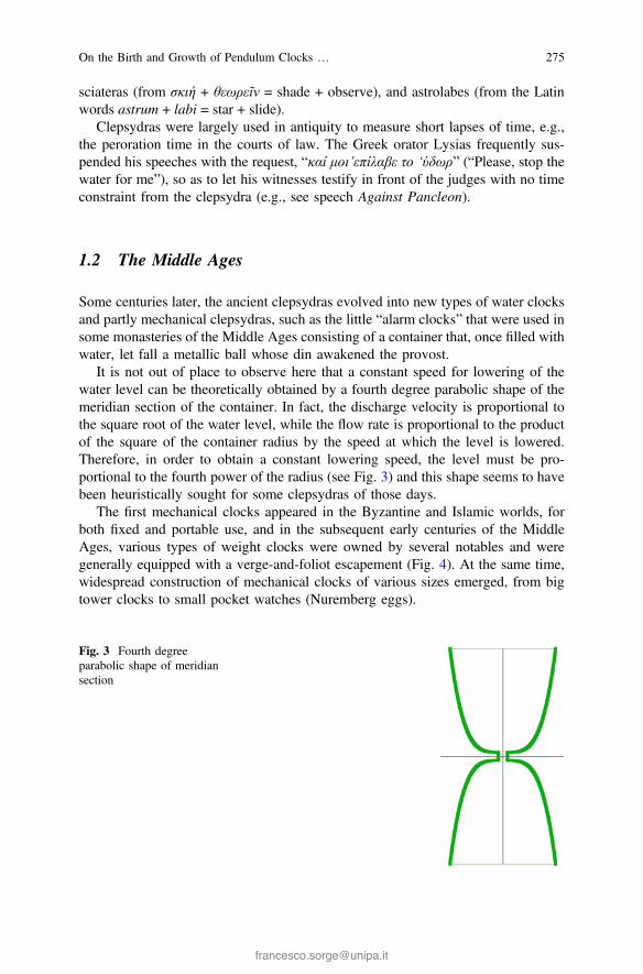
It is not out of place to observe here that a constant speed for lowering of thewater level can be theoretically obtained by a fourth degree parabolic shape of themeridian section of the container. In fact, the discharge velocity is proportional tothe square root of the water level, while the flow rate is proportional to the productof the square of the container radius by the speed at which the level is lowered.Therefore, in order to obtain a constant lowering speed, the level must be pro-portional to the fourth power of the radius (see Fig. 3) and this shape seems to havebeen heuristically sought for some clepsydras of those days.
The first mechanical clocks appeared in the Byzantine and Islamic worlds, forboth fixed and portable use, and in the subsequent early centuries of the MiddleAges, various types of weight clocks were owned by several notables and weregenerally equipped with a verge-and-foliot escapement (Fig. 4). At the same time,widespread construction of mechanical clocks of various sizes emerged, from bigtower clocks to small pocket watches (Nuremberg eggs).
Fig. 3 Fourth degreeparabolic shape of meridiansection
On the Birth and Growth of Pendulum Clocks … 275

In the medieval period, the start of the hour count was different in respectiveEuropean countries, though always with the same daily division of 24 h. Italy andBohemia adopted the “hora italica” and “hora bohemica”, both from one sunset tothe next, France used the “hora gallica”, from midnight to midnight, and Britishcountries used the “hora britannica”, from one sunrise to the next.
This period saw modern clock mechanisms assume their structure gradually, astructure that has somehow been present in all successive clocks, right up to thepresent day, though with a great number of refinements and improvements. Theso-called “main” mechanism comprises the driving motor, the gear transmissionand the dial plate with the hands, while the “secondary” mechanisms include: thecharging system, which restores the potential energy; the distribution system orescapement, which transforms the uniform motion generated by the motor into aperiodic series of small progressive movements; and the regulation mechanism, thetask of which is to ensure a constant oscillation period.
The foliot regulation system dates from before 1285 AD, in which year we learnabout the presence of this type of device in Old St. Paul’s in London (Fig. 4). Thefoliot, the etymon of which is probably linked to the old French verb folier (to playor dance foolishly), was a horizontal balance bar carrying two weights, which
The presence of the verge-and-foliot mechanism in Old St Paul's, London, is documented in 1285
Fig. 4 Verge-and-foliot escapement. From “Encyclopédie, ou Dictionnaire Raisonné desSciences, des Arts et des Métiers”, edited by Denis Diderot and Jean le Rond d’Alembert inParis, 1751–1772. The presence of the verge-and-foliot mechanism in Old St Paul’s, London, isdocumented in 1285
276 F. Sorge et al.
oscillated and interacted with a crown wheel through two pallets out of phase(Fig. 4). As no restoring force was acting on the system, the periodicity was referredto the foliot’s inertia, so that the time measurement was highly inaccurate (Diderotand d’Alembert 1751–1772) .
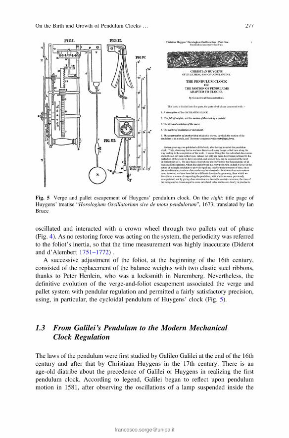
A successive adjustment of the foliot, at the beginning of the 16th century,consisted of the replacement of the balance weights with two elastic steel ribbons,thanks to Peter Henlein, who was a locksmith in Nuremberg. Nevertheless, thedefinitive evolution of the verge-and-foliot escapement associated the verge andpallet system with pendular regulation and permitted a fairly satisfactory precision,using, in particular, the cycloidal pendulum of Huygens’ clock (Fig. 5).
1.3 From Galilei’s Pendulum to the Modern MechanicalClock Regulation
The laws of the pendulum were first studied by Galileo Galilei at the end of the 16thcentury and after that by Christiaan Huygens in the 17th century. There is anage-old diatribe about the precedence of Galilei or Huygens in realizing the firstpendulum clock. According to legend, Galilei began to reflect upon pendulummotion in 1581, after observing the oscillations of a lamp suspended inside the
Fig. 5 Verge and pallet escapement of Huygens’ pendulum clock. On the right: title page ofHuygens’ treatise “Horologium Oscillatorium sive de motu pendulorum”, 1673, translated by IanBruce
On the Birth and Growth of Pendulum Clocks … 277
Cathedral of Pisa. He had the ingenious intuition that the oscillation period wassomehow independent of the amplitude and conceived the functional dependence ofthe pendular period on the suspension length and the suspended weight.
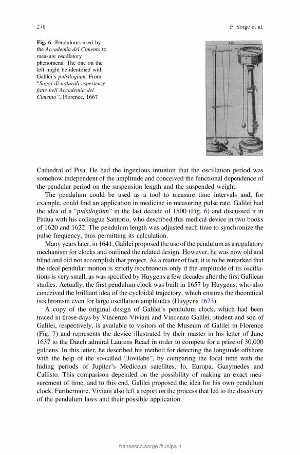
The pendulum could be used as a tool to measure time intervals and, forexample, could find an application in medicine in measuring pulse rate. Galilei hadthe idea of a “pulsilogium” in the last decade of 1500 (Fig. 6) and discussed it inPadua with his colleague Santorio, who described this medical device in two booksof 1620 and 1622. The pendulum length was adjusted each time to synchronize thepulse frequency, thus permitting its calculation.
Many years later, in 1641, Galilei proposed the use of the pendulum as a regulatorymechanism for clocks and outlined the related design. However, he was now old andblind and did not accomplish that project. As a matter of fact, it is to be remarked thatthe ideal pendular motion is strictly isochronous only if the amplitude of its oscilla-tions is very small, as was specified by Huygens a few decades after the first Galileanstudies. Actually, the first pendulum clock was built in 1657 by Huygens, who alsoconceived the brilliant idea of the cycloidal trajectory, which ensures the theoreticalisochronism even for large oscillation amplitudes (Huygens 1673).
A copy of the original design of Galilei’s pendulum clock, which had beentraced in those days by Vincenzo Viviani and Vincenzo Galilei, student and son ofGalilei, respectively, is available to visitors of the Museum of Galilei in Florence(Fig. 7) and represents the device illustrated by their master in his letter of June1637 to the Dutch admiral Laurens Reael in order to compete for a prize of 30,000guldens. In this letter, he described his method for detecting the longitude offshorewith the help of the so-called “Jovilabe”, by comparing the local time with thehiding periods of Jupiter’s Medicean satellites, Io, Europa, Ganymedes andCallisto. This comparison depended on the possibility of making an exact mea-surement of time, and to this end, Galilei proposed the idea for his own pendulumclock. Furthermore, Viviani also left a report on the process that led to the discoveryof the pendulum laws and their possible application.
Fig. 6 Pendulums used bythe Accademia del Cimento tomeasure oscillatoryphenomena. The one on theleft might be identified withGalilei’s pulsilogium. From“Saggi di naturali esperienzefatte nell’Accademia delCimento”, Florence, 1667
278 F. Sorge et al.

Figure 8 shows a reconstruction of the pendulum clock with the Galileiescapement, which was realized in 1879 by the Florentine clock-maker EustachioPorcellotti on the basis of Viviani’s design and is preserved in the Museum ofGalilei as well.
In spite of such previous studies by Galilei, the invention of the pendulum clockwas claimed in 1658 by Huygens, whose primacy was hotly contested by Viviani.
Fig. 7 Copy of the design of Galilei’s clock mechanism by Vincenzo Viviani and VincenzoGalilei. Copyright of Museo Galileo, photographic archives, Florence
On the Birth and Growth of Pendulum Clocks … 279

It is reported that, observing Viviani’s designs, Huygens sharply declared: “Itcannot work!”.
Regulation by the balance-wheel-coil-spring system was later introduced byHooke in the late 17th century, and in the meantime, the escapement evolved from theverge to the anchor, which was introduced by Clement in 1670, and then to theescapements of the deadbeat, cylinder and lever types, which were realized byGraham, Tompion and Mudge, respectively, in the 18th century, reaching a higherprecision due to the elimination of any recoil movement (Fig. 9). Later on, the clockstructure and the working technique would basically remain nearly unalteredthroughout the modern and contemporary ages, until the recent appearance of electricclocks, which, however, did not cause the disappearance of mechanical clocks(Heidrick 2002).
Fig. 8 Reconstruction ofGalilei’s pendulum clock byEustachio Porcellotti (1879).Copyright of Museo Galileo,photographic archives,Florence
Fig. 9 Escapement of later centuries: a deadbeat escapement of Graham; b cylinder escapementof Tompion; c lever escapement of Mudge (Audemars Piguet)
280 F. Sorge et al.
2 Pendular Motion
2.1 The Pendulum Isochronism
Galilei described the pendular mechanism for clocks in great detail in 1641, but hedid not accomplish that project owing to the infirmity of his age. Taking up a pointdiscussed above, the ideal motion of the simple pendulum tends to become iso-chronous only if the amplitude of its oscillations is very small. When Huygensbased his 1657 pendulum clock on the brilliant idea of cycloidal trajectory, theisochronism derived from the tautochronous property of the cycloid.
The study of the cycloid started with Galilei and continued with Fermat,Huygens, Newton and Bernoulli. Some relevant properties are:
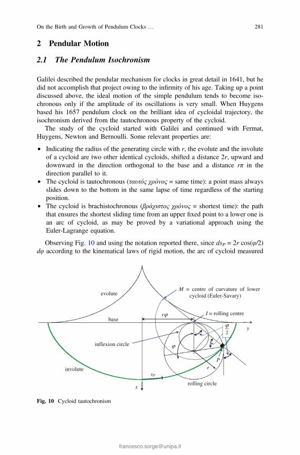
• Indicating the radius of the generating circle with r, the evolute and the involuteof a cycloid are two other identical cycloids, shifted a distance 2r, upward anddownward in the direction orthogonal to the base and a distance rπ in thedirection parallel to it.
• The cycloid is tautochronous (ταυτός χρόνος = same time): a point mass alwaysslides down to the bottom in the same lapse of time regardless of the startingposition.
• The cycloid is brachistochronous (βράχιστος χρόνος = shortest time): the paththat ensures the shortest sliding time from an upper fixed point to a lower one isan arc of cycloid, as may be proved by a variational approach using theEuler-Lagrange equation.
Observing Fig. 10 and using the notation reported there, since dsP = 2r cos(φ/2)dφ according to the kinematical laws of rigid motion, the arc of cycloid measured
rϕ
x
y
I = rolling centre
M = centre of curvature of lower cycloid (Euler-Savary)
2ϕ
inflexion circle
P
ϕ
sP
rolling circle
base
r
evolute
involute
Fig. 10 Cycloid tautochronism
On the Birth and Growth of Pendulum Clocks … 281

from the bottom may be written in the form sP = 4r sin(φ/2), where r is the radius ofthe generating circle, φ is its rolling angle and φ/2 is also the local slope at P. Thus,the gravitational restoring force is proportional to sP and the equilibrium of thepoint mass P along the path yields,
m€sP ¼ �mg sinu2
� �
! €sP ¼ � gsP4r
! _s2P ¼ � g4r
s2P � s2P;max:
� �
; ð1Þ
whence, integrating again, the sliding time from the top position to the bottom turnsout to be the same for any starting position:
Tsliding2
ffiffiffi
gr
r
¼ sin�1 sPsP;max:
� ��
�
�
�
�
�
�
�
sP;max :
0¼ sin�1 1ð Þ ! Tsliding ¼ p
ffiffiffi
rg
r
: ð2Þ
The tautochronous property of the cycloidal path was experimentally proved bythe Dutch scientist W.J. Gravesande, using the device shown in Fig. 11, which wasdescribed in his treatise “Physices Elementa Mathematica” and has been recently
Fig. 11 a Gravesande’s treatise “Physices Elementa Mathematica”. b Willem Jacob’sGravesande. c Device for experimental tests on the cycloid tautochronism (by Gravesande).d Reconstruction of Gravesande’s device by Museum Galileo, Florence. Copyright of MuseoGalileo, photographic archives, Florence
282 F. Sorge et al.

reconstructed by the “Museo Galileo” in Florence. Letting two balls roll along twoidentical cycloidal tracks, starting from two different rest positions, they arrivetogether at the bottom, though they cross the finishing line with different velocitiesbecause of the law of the conservation of energy (see Eq. 1).
The tautochronous property of the cycloid is strictly associated with theisochronism of the cycloidal pendulum. Figure 12 shows that, when the flexible redribbon OMP oscillates, wrapping and unwrapping the two rigid cycloidal bandsgenerated by a circle of diameter 2r, the point mass P, which is located at a distance4r on the ribbon, describes a cycloidal trajectory equal to those bands, but shifted adistance 2r in the downward direction and symmetrically placed between them(involute of the upper rigid cycloids).
Actually, as sM = 4r − MP = 4r − MP0 = 4r[1 − sin(π/2 − ψ/2)] (see Fig. 10 andprevious discussion on tautochronism), one has
xP ¼ xM þ 4r � sMð Þ cos w=2ð Þ¼ r 1� coswð Þþ 4r cos2 w=2ð Þ ¼ 2rþ r 1þ coswð Þ;
yP ¼ yM þ 4r � sMð Þ sin w=2ð Þ¼ r w� sinwð Þþ 4r sin w=2ð Þ cos w=2ð Þ ¼ r wþ sinwð Þ;
ð3a; bÞ
which are just the parametric equations of the lower cycloid.
yO
sM
γψ
2
ψM
P
r
r
Q
R (circular path of Q)
ψ
sP
x
rigid cycloidal band
cycloidal path of P
OMP = OMP0 = 4r
swinging rod regulating the crown wheel rotation by two pallets forming an angle of nearly 100°
P'
M'
P022
ψπ −
Fig. 12 Isochronism of the cycloidal pendulum
On the Birth and Growth of Pendulum Clocks … 283

The oscillation period is four times the time interval elapsed between themaximum amplitude position and the bottom position, and thus, the oscillations areisochronous due to the tautochronism properties of the cycloidal path.
The brachistochronous property of the cycloids is also interesting, though ofminor concern for the pendular motion. The space covered by a point mass to slidefrom a fixed upper position to a fixed lower position along a generic path should becalculated by integrating the following expression:
dsdt
¼ dydt
ffiffiffiffiffiffiffiffiffiffiffiffiffiffiffiffiffiffiffiffiffiffi
1þ dxdy
� �2s
¼ffiffiffiffiffiffiffiffiffiffiffiffiffiffiffiffiffiffiffiffiffi
2g x0 � xð Þp
; ð4Þ
where the subscript 0 indicates the starting level. Hence, putting x0 − x = X andindicating with a prime the differentiation with respect to y, one has
ffiffiffiffiffi
2gp
� dt ¼ dy�ffiffiffiffiffiffiffiffiffiffiffiffiffiffi
1þX 02
X
r
¼ dy� f X;X 0ð Þ where f ¼ffiffiffiffiffiffiffiffiffiffiffiffiffiffi
1þX 02
X
r
: ð5a; bÞ
The condition that the sliding time to pass from level x0 to level x < x0 is theshortest one implies minimization of the integral of the right hand of Eq. (5a) fromy0 to y, whence the Euler-Lagrange equation is
dfdX
� ddy
dfdX 0
� �
¼ 0: ð6Þ
Replacing the function f by Eq. (5b), the solution of Eq. (6) can be found to be X(1 + X′2) = constant = 2r, which gives X 0 ¼ � ffiffiffiffiffiffiffiffiffiffiffiffiffiffiffiffiffiffiffi
2r=X � 1p
. Hence one gets, inte-grating again,
� y� y0ð Þ ¼ffiffiffiffiffiffiffiffiffiffiffiffiffiffiffiffiffiffiffiffiffi
X 2r � Xð Þp
þ 2r tan�1ffiffiffiffiffiffiffiffiffiffiffiffiffiffiffiffiffiffiffi
2r=X � 1p
: ð7Þ
This is just the Cartesian equation of the cycloid passing through the point(x0, y0) and stemming from the rolling motion of a circle of radius r under a straighthorizontal base line. Actually, replacing X = r(1 + cosψ), (y − y0) = ±r(ψ + sinψ)into Eq. (7), an identity is obtained.
2.2 The Structure of Galilei’s Clock Mechanism. Idealand Actual Operation
The ideal oscillation period of the simple pendulum may be calculated bywell-known procedures ignoring the impulse supply and the energy dissipation inthe whole clock mechanism. Defining the swing angle by θ (e.g., positive in theanticlockwise direction), introducing the dimensionless time variable τ = ωnt, where
284 F. Sorge et al.
ωn =ffiffiffiffiffiffiffi
g=lp
and indicating the derivatives with respect to τ with primes, the motionequation shows the familiar trigonometric law of the restoring force
h00 þ sin h ¼ 0: ð8Þ
The first integration gives
h02
2¼ 2 sin2
H2� sin2
h2
� �
; ð9Þ
where Θ is the oscillation amplitude.Hence, putting sin2(Θ/2) = k2 and sin2(θ/2) = k2sin2u, the change of the variable
from θ to u leads to a Legendre normal form, which permits calculating thedimensionless oscillation period T by the second integration
ds ¼ duffiffiffiffiffiffiffiffiffiffiffiffiffiffiffiffiffiffiffiffiffiffiffiffi
1� k2 sin2 up ! T ¼ 4K kð Þ ¼ 4K sin
H2
� �
; ð10a; bÞ
where K(k) stands for the complete elliptic integral of the first kind with modulusk. This result reveals the dependence of the period on the swing amplitude and, asthe complete elliptic integral K(k) is equal to π/2 for k = 0 and is an increasingfunction of k, the period decreases monotonicly on decreasing the amplitude andapproaches the harmonic period 2π for small oscillation widths.
The cycloidal pendulum described by Huygens in his treatise “HorologiumOscillatorium sive de motu pendulorum” in 1673 is not affected by this drawback,because it is based on the tautochronous property of the cycloidal trajectory, alongwhich a point mass always slides down in the same lapse of time under theinfluence of gravity regardless of its starting position.
However, a deeper reflection is here advisable on the fact that, strictly speaking,all the above considerations on the ideal isochronism or non-isochronism of pen-dular motion are somewhat illusory in practice, due to the unavoidable frictionlosses present in the whole clock assembly and to the consequent impulse supplynecessary to provide the dissipated energy periodically.
Figure 13 shows a mechanical reconstruction of Galilei’s clock prototype on thebasis of Viviani’s design and clearly highlights the functionality of the Galileanescapement. The escapement wheel has ten ratchets on the crown and ten frontpegs. Its intermittent motion is controlled by a catch, which is slightly loaded by athin spring, and by two curved levers fastened to the pendulum hinge.
On approaching the left dead position of the pendulum near the oscillation end,for a certain angle θ1 < 0, the upper releasing lever raises the catch until the wheel isleft free and rotates to contact the lower impulse lever with its peg (pendulumposition θ2). After a short recoil to reach the dead position, the wheel peg pushes theimpulse lever until leaving it for θ = θ3, near the right dead position, providing theenergy lost by friction during the cycle.
On the Birth and Growth of Pendulum Clocks … 285
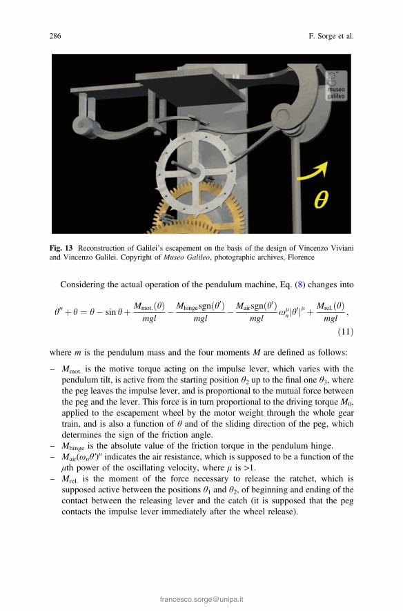
Considering the actual operation of the pendulum machine, Eq. (8) changes into
h00 þ h ¼ h� sin hþ Mmot: hð Þmgl
�Mhingesgn h0ð Þmgl
�Mairsgnðh0Þmgl
xln h
0j jl þ Mrel: hð Þmgl
;
ð11Þ
where m is the pendulum mass and the four moments M are defined as follows:
– Mmot. is the motive torque acting on the impulse lever, which varies with thependulum tilt, is active from the starting position θ2 up to the final one θ3, wherethe peg leaves the impulse lever, and is proportional to the mutual force betweenthe peg and the lever. This force is in turn proportional to the driving torque M0,applied to the escapement wheel by the motor weight through the whole geartrain, and is also a function of θ and of the sliding direction of the peg, whichdetermines the sign of the friction angle.
– Mhinge is the absolute value of the friction torque in the pendulum hinge.– Mair(ωnθ′)
μ indicates the air resistance, which is supposed to be a function of theμth power of the oscillating velocity, where μ is >1.
– Mrel. is the moment of the force necessary to release the ratchet, which issupposed active between the positions θ1 and θ2, of beginning and ending of thecontact between the releasing lever and the catch (it is supposed that the pegcontacts the impulse lever immediately after the wheel release).
Fig. 13 Reconstruction of Galilei’s escapement on the basis of the design of Vincenzo Vivianiand Vincenzo Galilei. Copyright of Museo Galileo, photographic archives, Florence
286 F. Sorge et al.
The dissipative torqueMhinge in the pendulum hinge is piece-wise continuous andconstant and changes its direction at the motion inversion, whereas the torque Mair,due to the air resistance, is continuous and depends on the oscillation speed. Thesetwo torques are both active during the whole period. The releasing torque Mrel. maybe assumed constant but is active only during a short fraction of the period. Themoving torque Mmot. is also active during a partial fraction of the oscillation period,from θ2 to θ3, and though the driving torqueM0 exerted on the escapement wheel bythe gears may be plausibly considered constant, yetMmot. varies with the position onthe impulse lever of the contact point with the peg and also depends on the directionof the sliding friction. The total force between the peg and the lever can be calculatedby the rotational equilibrium condition of the escapement wheel and permits cal-culating Mmot. by imposing the rotational equilibrium of the impulse lever. Therelation between Mmot. and M0 is somewhat complex and is not reported. Here, it isonly mentioned that this relation depends on the pendulum angle θ, on the radialposition of the pegs, on their diameter, on the angle between the lever and thependulum rod, on the offset of the lever with respect to the centre of the pendulumhinge and on the sliding direction.
Assuming one of the previous tilt angles θ as a small reference parameter ε, e.g.,θ1 = ε, scaling all the angles θ by ε and minding the series expansion of the sinefunction, the difference θ − sinθ is of order ε3. If one supposes that all fourdimensionless moments of Eq. (11) exert an influence on the pendulum motion thatis comparable with the gravitational nonlinearity, they must be regarded as of orderε3 as well. Otherwise, some of them may be regarded as of a lower or higher orderof magnitude, i.e., of order εn with n ≠ 3.
The right hand of Eq. (11) is characterized by discontinuities of the first kind,but, looking only for a first order approximation of the solution, an averagingapproach of the Krylov-Bogoliubov (K-B) type appears appropriate (Krylov andBogoliubov 1947). Putting θ = εβ, letting β = Bsin(τ + ϕ) be the zero order solution(for ε→ 0) and indicating the right hand of Eq. (11) with ε3F(β), the K-B procedureassumes that B and ϕ are not two constants but two functions of τ and eliminates thenew degree of freedom that is being introduced by imposing the further conditionβ′ = B cos(τ + ϕ), whence
B0 sin sþ/ð ÞþBu0 cos sþ/ð Þ ¼ 0;
B0 cos sþ/ð Þ � B/0 sin sþ/ð Þ ¼ e2F bð Þ; ð12a; bÞ
and consequently,
B0 ¼ e2F bð Þ cos sþ/ð Þ; B/0 ¼ �e2F bð Þ sin sþ/ð Þ: ð13a; bÞ
Equations (13a, b) imply that B and ϕ are slowly varying functions of τ, and thus,they can be approximately averaged in the short period 2π neglecting theirvariation:
On the Birth and Growth of Pendulum Clocks … 287

B0 ffi e2
2p
Z
2p
0
F bð Þ cos sþ/ð Þd sþ/ð Þ;
B/0 ffi � e2
2p
Z
2p
0
F bð Þ sin sþ/ð Þd sþ/ð Þ:ð14a; bÞ
Therefore, fixing the functional dependence on θ of the three dimensionlessdissipative moments, Mhinge/(mgl), Mair(ωnε)
μ/(mgl) and Mrel./(mgl), which arecontained in F(β), and assuming steady oscillations (B′ = 0), it is possible to solvefor the required driving torque M0 and for the frequency change ωnϕ′ depending onthe oscillation amplitude Θ = εB.
Figure 14 illustrates these results with an example case and shows the differencebetween two choices of the order of magnitude of the four moments M(…) inEq. (11): n = 2 indicates that the nonlinear gravitational effect is of a lower order,whereas this effect is comparable with the dissipative and impulsive effects forn = 3. The red curve gives the theoretical dependence of the period on the amplitudeand corresponds to an exponent n ≫ 3. The exponent μ of the air resistance wasfixed to the value μ = 1.5, in the implicit hypothesis of an intermediateviscous-turbulent condition. What is most interesting in the results is that the overalleffect of the driving impulse and the dissipation sources somehow counterbalancesthe period increase of the ideal pendulum in increasing the oscillatory amplitudeand may even isochronize the motion in particular conditions under which thenonlinear effects are all comparable with each other.
M0 /mgl
(ω −ωn) /ωn
(T0−T) /T
0° 5° 10° 15° 20°
0.10
0.05
0.00
-0.05
θ1 = −5° θ2 = −8° θ3 = 5° μ = 1.5Mhinge = 0.2×mgl n
Mairωnμ = 0.2×mgl n−μ
Mrel. = 0.2×mgl n
n = 2 (negligible effect of gravitational nonlinearity)
n = 3 (same order of magnitude of all nonlinear terms)
− θ2
Θ
n (ideal pendulum with negligible dissipation)
Fig. 14 Dimensionless driving torque on escapement wheel M0/mgl (in green) and angularfrequency relative change (ω − ωn)/ωn (in blue) versus oscillation amplitude Θ, for two values ofthe order n. Nonlinear period change of ideal pendulum (in red), T0 = 2π, T = 4K(k)
288 F. Sorge et al.
3 Conclusive Remarks
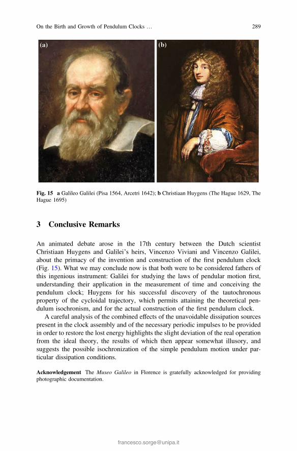
An animated debate arose in the 17th century between the Dutch scientistChristiaan Huygens and Galilei’s heirs, Vincenzo Viviani and Vincenzo Galilei,about the primacy of the invention and construction of the first pendulum clock(Fig. 15). What we may conclude now is that both were to be considered fathers ofthis ingenious instrument: Galilei for studying the laws of pendular motion first,understanding their application in the measurement of time and conceiving thependulum clock; Huygens for his successful discovery of the tautochronousproperty of the cycloidal trajectory, which permits attaining the theoretical pen-dulum isochronism, and for the actual construction of the first pendulum clock.
A careful analysis of the combined effects of the unavoidable dissipation sourcespresent in the clock assembly and of the necessary periodic impulses to be providedin order to restore the lost energy highlights the slight deviation of the real operationfrom the ideal theory, the results of which then appear somewhat illusory, andsuggests the possible isochronization of the simple pendulum motion under par-ticular dissipation conditions.
Acknowledgement The Museo Galileo in Florence is gratefully acknowledged for providingphotographic documentation.
Fig. 15 a Galileo Galilei (Pisa 1564, Arcetri 1642); b Christiaan Huygens (The Hague 1629, TheHague 1695)
On the Birth and Growth of Pendulum Clocks … 289

References
Diderot D, d’Alembert JlR (eds) (1751–1772) Encyclopédie, ou Dictionnaire Raisonné desSciences, des Arts et des Métiers, Paris
Headrick MV (2002) Origin and evolution of the anchor clock escapement. IEEE control systemsmagazine, April 2002
Huygens C (1673) Horologium Oscillatorium sive de motu pendulorum (trans: Bruce I)Krylov N, Bogoliubov N (1947) Introduction to non-linear mechanics. Princeton University Press,
New Jersey
290 F. Sorge et al.

![L 21 – Vibration and Sound [1] Resonance Tacoma Narrows Bridge Collapse clocks – pendulum springs harmonic motion mechanical waves sound waves musical](https://img.pdfslide.us/doc/110x75/5a4d1ace7f8b9ab0599709b7/l-21-vibration-and-sound-1-resonance-tacoma-narrows-bridge-collapse.jpg)

![L 23 – Vibrations and Waves [3] resonance clocks – pendulum springs harmonic motion mechanical waves sound waves golden rule for waves Wave](https://img.pdfslide.us/doc/110x75/56649e485503460f94b3b92e/l-23-vibrations-and-waves-3-resonance-clocks-pendulum-springs.jpg)


![L 22 – Vibrations and Waves [3] resonance clocks – pendulum springs harmonic motion mechanical waves sound waves golden rule for waves Wave](https://img.pdfslide.us/doc/110x75/56649e485503460f94b3b92b/l-22-vibrations-and-waves-3-resonance-clocks-pendulum-springs.jpg)
![L 22 – Vibrations and Waves [2] resonance clocks – pendulum springs harmonic motion mechanical waves sound waves musical instruments](https://img.pdfslide.us/doc/110x75/56649f2a5503460f94c44e28/l-22-vibrations-and-waves-2-resonance-clocks-pendulum.jpg)

![L 21 – Vibrations and Waves [1] resonance Tacoma Narrows Bridge Collapse clocks – pendulum springs harmonic motion mechanical waves sound](https://img.pdfslide.us/doc/110x75/56649cb05503460f94975565/l-21-vibrations-and-waves-1-resonance-tacoma-narrows-bridge-collapse.jpg)

![L 23a – Vibrations and Waves [4] resonance clocks – pendulum springs harmonic motion mechanical waves sound waves golden rule](https://img.pdfslide.us/doc/110x75/56649ea05503460f94ba3d4f/l-23a-vibrations-and-waves-4-resonance-clocks-pendulum.jpg)


![L 23 – Vibrations and Waves [3] resonance clocks – pendulum springs harmonic motion mechanical waves sound waves golden rule for](https://img.pdfslide.us/doc/110x75/56649f455503460f94c6636b/l-23-vibrations-and-waves-3-resonance-clocks-pendulum.jpg)