Embed Size (px)
Citation preview
Journal of the Korean Society of Marine Engineering, Vol. 35, No. 7, pp. 946~956, 2011(ISSN 1226-9549)
http://dx.doi.org/10.5916/jkosme.2011.35.7.946
946 / Journal of the Korean Society of Marine Engineering, Vol. 35, No. 7, 2011. 11
On the Application of CFD Codes for Natural Gas Dispersion and Explosionin Gas Fuelled Ship
Ki-Pyoung Kim1․Ho-Keun Kang†․Choung-Ho Choung
1․Jae-Hong Park
1
(Received November 15, 2011; Revised November 21, 2011; Accepted November 28, 2011)
Abstract:The main objectives of this study are to analyze the leaked gas dispersion and quantify the potential overpressures due to vapor cloud explosions in order to identify the most significant contributorsto risk by using Computational Fluid Dynamics (CFX & FLACS) for gas fuelled ships. A series of CFD simulations and analyses have been performed for the various gas release scenarios in a closed module, covering different release rates and ventilating methods. This study is specially focused on the LNG FGS (Fuel Gas Supply) system recently developed for the propulsion of VLCC crude oil carriers by shipyards. Most of work presented is discussed on the gas dispersion from leaks in the FGS room, and shows some blast prediction validation examples.Key words:Gas Fuelled Ship, FGS System, CFD, Gas Dispersion, Explosion
†Corresponding Author(Maritime Technology Research, Korean Register of Shipping, E-mail: [email protected], Tel:042-869-9215)1 Maritime Technology Research, Korean Register of Shipping
This paper is extended and updated from the short version that apeared in the Proceedings of the International symposium on Marine Engineering and Technology (ISMT 2011), held at BEXCO, Busan, Korea on October 25-28, 2011.
1. IntroductionAs part of provision for the current international
movements in the shipping industry on fighting global warming through reducing GHG emission in air, new design concepts using natural gas as an alternative fuel source for propulsion of large commercial vessels, such as VLCC/AFRAMAX crude oil carriers, have been studied by Korean ship yards. LNG FGS (Fuel Gas Supply) system to use LNG as fuel source was recently developed for the propulsion of VLCC crude oil carriers. The system design was focusing on the fuel gas supply process, which has the function of supplying natural gas from LNG storage tanks onboard to main engines of the vessel.
In order to identify all the possible hazards in the system and then enhance the system safety, a high‐level Hazard Identification (HAZID) study[1]
was carried out by a multi‐disciplinary HAZID team on 11th‐12th November, 2010, at DSME Okpo shipyard, Korea, under the lead of a HAZID facilitator. The HAZID analysis resulted in findings of 50 potential hazards as shown in Table 1 and then 95 recommendations for the identified potential hazards was drawn up and proposed. The recommendations represent issues that the HAZID team considered important to highlight therefore they need to be reviewed during the detailed design of the proposed LNG fuelled systems. As a result of some HAZID, gas leaks in a machinery room for pumps, compressor, heat exchanger and etc. identified as the main hazards in the design which deserved further analysis. As the analysis was conducted, it turned out many novel issues associated with the design where in the gas supply

On the Application of CFD Codes for Natural Gas Dispersion and Explosion in Gas Fuelled Ship 67
Journal of the Korean Society of Marine Engineering, Vol. 35, No. 7, 2011. 11 / 947
Table 2: Numerical conditionsDomain Grid Fluid Model Boundary Conditions Numerical SetupSkid size
14m(W)×
6m(L)×
2.5m(H)
‐ Tetrahedron + Hexaheron : > 2.5x10⁶ nodes
‐ Prisms smoothing: Solid walls
k‐ε two‐equation model
‐ Ventilating method: Case I : Forced air circulation Case II: Exhausted air
ventilation‐ Solid wall : no‐slip, adiabatic‐ Leak gas : CH4‐ Leak pressure: 6 bar‐ Leaked gas temperature: 10℃‐ FGS room temperature: 20℃
‐ Advection scheme: upwind‐ Residual target : < 10‐5‐ Residual type : RMS‐ Constant time step: 0.001 sec
system, and had to do with gas leakage in various conditions.
This study specifically focused on the analysis of gas dispersion conditions and near‐field blast waves in order to understand the risk posed by the different gas leakages and the ventilating methods, and identify the most significant contributors to risk, to propose risk reducing recommendations that will develop IGF code at IMO.
Table 1: Specific number of the identified hazards classified by the risk ranking
Risk ranking Number of findingsH 5M 15L 27
Not ranked 3
CFD (Computational Fluid Dynamics) has established itself as a valuable tool for risk assessment and safety analysis in process industries and design of new concept ships. Increasing use of the CFD is seen in evaluating the risk from dispersion/explosion applications in the coming years. CFD models can also evaluate detailed dynamic effects in the near field, which include time dependent pressure loads as well as dispersion and focusing of the blast waves.
The main objectives of the study are:▪ to identify potential gas release scenarios▪ create a 3‐D modeling of the FGS room, and
perform a CFD dispersion analysis of representative release scenarios evaluating various environmental
conditions, especially ventilating method▪ perform explosion modeling▪ evaluate the ventilation efficiency required in
RES.MSC.285(86) [2] at IMO
2. Numerical MethodologyIn the open literature, there are at least four
CFD codes that may be used for LNG vapor dispersion/explosion modeling where details in the setting up may be found: FEM3 CFD, FLACS, FLUENT, and CFX. CFX and FLUENT are general‐purpose CFD codes but specific CFD ones. The use of generic CFD codes such as CFX[3] and FLACS[4] was more appropriate for this type of work than specific CFD codes because of the flexibility of setting up.
The governing equations used in the present numerical study are the three‐dimensional, time dependent continuity, momentum and energy equations employing a turbulence model for unsteady Navier‐Stokes equation in CFD code.
Release modelling is mainly used to determine the rate at which fluid/gas is released to the environment in a loss of containment incident or pipeline raptures, together with the associated physical properties. A simple approach is to calculate the initial rate and to assume that this is constant over time. This is often used for studies of onshore facilities, especially where the offsite risk is the motivation. Where gas or non‐flashing liquid would be released from an orifice, simple formulae exist to calculate the initial rate, in particular

68 Ki-Pyoung Kim․Ho-Keun Kang․Choung-Ho Choung․Jae-Hong Park
948 / Journal of the Korean Society of Marine Engineering, Vol. 35, No. 7, 2011. 11
Table 3: Gas release scenarios by Eq.(1) selected for the modelingNo. Leak hole Diameter [mm] Time to leak [sec] Mass flow of air [kg/sec] Mass flow of CH4 [kg/sec]
Case 1 12.7 8 1.5 (Over pressure type) 0.0994Case 2 25.4 8 1.5 (Over pressure type) 0.3978Case 3 38.1 8 1.5 (Over pressure type) 0.8951Case 4 50.8 8 1.5 (Over pressure type) 1.5912Case 5 50.8 8 1.5 (Under pressure type) 1.5912
Bernoulli’s equation for liquids. Modelling releases from ruptured pipelines is rather more complex as the pipeline pressure decreases away from the release point over time and so the flow rate decreases with time, especially for gases.
Formulas below are used to estimate the required effective leaking gas when the flow is subcritical flow. Under this condition the formula (Daniel and Joseph, 1990[5]) used for calculation of the leaking gas can be assumed as follows.
)1/()1(
11 1
2−+
⎟⎟⎠
⎞⎜⎜⎝
⎛+
=γγ
γγ
RTMg
APCQ WcD (1)
Where,Q: flow rate (kg/sec)CD: Coefficient of leakage, dimensionlessP1: Operating gas pressure (kgf/cm2)
No.1 BOG compressorNo.2 BOG compressor
Recondenser
Glycol heating systemNG HP Cooler
No.1 HP Pump No.2 HP Pump
HP Vaporizer
Vent Inlet
Vent Outlet
Gas Leakage
No.1 BOG compressorNo.2 BOG compressor
Recondenser
Glycol heating systemNG HP Cooler
No.1 HP Pump No.2 HP Pump
HP Vaporizer
Vent Inlet
Vent Outlet
Gas Leakage
xyz
Figure 1: Schematic diagram and boundary conditions for FGS machinery space (Released by DSME[1])
Gc: Gravity (9.8 kg m/kgf)Mw: Molecular weight for gas or vapor(kg/kg‐mole)A: Leakage area (m2)T1: Operating temperature (K)R: Gas constant (847 m kgf/kg‐mole)
γ : Specific heat ratio of gas or vapour (Cp/Cv)
3. CFD Analysis3.1 Gas Dispersion
3.1.1 Initial and Boundary ConditionsThe compressors or HP pumps in the FGS room
pressurize natural or forced boil‐off gas from the fuel storage tank for use in the dual fuel/gas only engine that provide ship propulsion. The FGS room is located on the main deck near the aft of the vessel on the port side and the schematic diagram is presented in Figure 1(a). The approximate volume of the FGS room is estimated 210 m3
(14m(W) x 6m(L) x 2.5m(H)). Venting of the room involved one air intake and two air exhaust fans, all located in the roof. A gaseous release was introduced in CFX as a pure gas like CH4 at specified flow rate, velocity, turbulence and temperature. Our approach is followed, for example, to simulate a jet from a gas leak in a pressurized system. For LNG gas dispersion, air and CH4 are usually modeled as gas phase, and their physical properties must be temperature dependent. CH4 gas density must be around 1.78 kg/m3 at 110 K to 0.45 kg/m3 at 300 K. CFX uses the Boussinesq model (ANSYS, 2010) to predict the turbulence inside the cloud as function of the thermal expansivity, set to 0.00366 K‐1.
(a)
(b)

On the Application of CFD Codes for Natural Gas Dispersion and Explosion in Gas Fuelled Ship 69
Journal of the Korean Society of Marine Engineering, Vol. 35, No. 7, 2011. 11 / 949
Mass Fraction of CH4 in range 0~50,000ppm (Case 1, Side view, Inlet, 4s) Mass Fraction of CH4 in range 0~50,000ppm (Case 1, Side view, Center, 4s)
Mass Fraction of CH4 in range 0~50,000ppm (Case 1, Side view, Inlet, 8s) Mass Fraction of CH4 in range 0~50,000ppm (Case 1, Side view, Center, 8s)
Mass Fraction of CH4 in range 0~50,000ppm (Case 1, Side view, Inlet, 50s) Mass Fraction of CH4 in range 0~50,000ppm (Case 1, Side view, Center, 50s)
(a) Case 1 (0~50 sec)
(b) Case 2 (0~50 sec)
Mass Fraction of CH4 in range 0~50,000ppm (Case 3, Side view, Inlet, 4s) Mass Fraction of CH4 in range 0~50,000ppm (Case 3, Side view, Center, 4s)
Mass Fraction of CH4 in range 0~50,000ppm (Case 3, Side view, Inlet, 8s) Mass Fraction of CH4 in range 0~50,000ppm (Case 3, Side view, Center, 8s)
Mass Fraction of CH4 in range 0~50,000ppm (Case 3, Side view, Inlet, 50s) Mass Fraction of CH4 in range 0~50,000ppm (Case 3, Side view, Center, 50s)
Mass Fraction of CH4 in range 0~50,000ppm (Case 3, Side view, Inlet, 120s) Mass Fraction of CH4 in range 0~50,000ppm(Case 3, Side view, Center, 120s)
(c) Case 3 (0~120 sec)(continued)

70 Ki-Pyoung Kim․Ho-Keun Kang․Choung-Ho Choung․Jae-Hong Park
950 / Journal of the Korean Society of Marine Engineering, Vol. 35, No. 7, 2011. 11
Mass Fraction of CH4 in range 0~50,000ppm (Case 4, Side view, Inlet, 4s) Mass Fraction of CH4 in range 0~50,000ppm (Case 4, Side view, Center, 4s)
Mass Fraction of CH4 in range 0~50,000ppm (Case 4, Side view, Inlet, 8s) Mass Fraction of CH4 in range 0~50,000ppm (Case 4, Side view, Center, 8s)
Mass Fraction of CH4 in range 0~50,000ppm (Case 4, Side view, Inlet, 50s) Mass Fraction of CH4 in range 0~50,000ppm (Case 4, Side view, Center, 50s)
Mass Fraction of CH4 in range 0~50,000ppm (Case 4, Side view, Inlet, 120s)Mass Fraction of CH4 in range 0~50,000ppm (Case 4, Side view, Inlet, 120s) Mass Fraction of CH4 in range 0~50,000ppm(Case 4, Side view, Center, 120s)Mass Fraction of CH4 in range 0~50,000ppm(Case 4, Side view, Center, 120s)
(d) Case 4 (0~120 sec)Figure 2: Concentration of CH4 at 4, 8, 50 and 120 seconds after gas leaks in the vertical plan of y=0.7 m and y=3.0 m, respectively.
The numerical analyses were carried out for assumed leaks inside the FGS room that fed high pressure natural gas to the engines, and the numerical setups shown in Table 2. The leak points assumed was located near the high pressure pump around the air intake as shown in Figure 1(b), and four different leak holes diameter were considered. Leak conditions modelled 6 bar line pressure, and a natural gas temperature of 10℃. A summary of the leak scenarios assumed is shown in Table 3. The mass flow rates of the leaks were calculated by Eq.(1), and the mass discharge rate was assumed to be constant. The monitoring points were located underneath air intake vent/exhaust vent and centre point of roof, respectively. Quantitative measurements of emission and concentration are important in order to estimate the total emission released from the leak, as well as to validate the ventilating conditions, because methane (CH4) is flammable within the range of 5~15%v/v in air.
3.1.2 Effects of Leak Hole DiameterFor a given leak scenario, Figures 2(a)‐2(d) represent
the concentration of methane (CH4) at different times (4, 8, 50 and 120 sec) in vertical plan of y=0.7 and y=3.0 m after the gas leak starts for 4 cases, respectively. In Case 1 to 3, the concentrations of CH4 dilute quickly due to the intake air from the vent, and, in current conditions, the results show that there leased gas do not reached the flammable gas after the gas leak stop, as shown in Figures 2(a), (b) and (c). But leak hole sizes of 50.8 mm (Case 4) in Figure 2(d) was shown to have a flammable volume in CH4 concentration above 50,000 ppm of the lower flammable limit (LFL), and the atmospheric condition was remained continuously after the gas leak stop.
Time(sec)
CH
4co
ncen
tratio
n(p
pm)
0 10 20 30 40 50 60 70 80 90 100 110 1200
10000
20000
30000
40000
50000
60000
70000
80000
Case 1Case 2Case 3Case 4
Figure 3: Time variations of CH4 mass fraction at center measuring points for 4 cases

On the Application of CFD Codes for Natural Gas Dispersion and Explosion in Gas Fuelled Ship 71
Journal of the Korean Society of Marine Engineering, Vol. 35, No. 7, 2011. 11 / 951
Figure 3 shows the time variations of CH4 mass fraction at 4 measuring points for four cases during 120 seconds. In these cases, the maximum flammable volumes were reached right before the leak terminated. After the leak stopped, the flammable volume would decrease slowly as the ventilation dilute the gas. The time for flammable gas to reach the measuring points varies slightly, but in general was approximately 4~6 seconds after the leak starts.
3.1.3 Effects of Ventilation ConditionsSeveral runs were performed to assess the effect
of ventilation efficiency in the closed modules as presented in Table 3. The results of ventilating method for pressurized types (over‐pressure or under‐pressure) in the FGS room were presented interesting features. Presently, the IGF interim guideline (Res.MSC.285(86)) requires to be fitted effective mechanical ventilation system of the under‐pressure type, that is the exhausted air ventilation (Case 5), providing a ventilation capacity of at least 30 air changes per hour. This ventilation rate corresponds to total mass flow of air equal to 5,400 kg/hour. The location of the inlet/exhaust ducts and the rates were based on drawings, engineering judgment and assumptions.
While the under pressure method like Case 5 may be sufficient for leaks in present system, the results of ventilation efficiency for the overpressure and under‐pressure methods showed that the overpressure type (Case 1 to 4) is more efficient than that of under‐pressure (Case 5) in our assessment. When the leak stops, the difference in degree of ventilating was obtained averagely 5% for residual CH4 volume, as shown in Figure 4. This difference can be explained by wind “meandering” caused by a blow opening, which could direct the gas cloud allowing it to disturb and spread. That is, wind speed fluctuations are likely to have a strong effect on the downwind dispersion of the gas cloud, especially in stable and low‐wind atmospheric conditions.
Time(sec)
Res
idua
lCH
4(kg
)
0 5 10 15 20 25 30 35 40
0
2
4
6
8
10
12
14
Case 4Case 5
Figure 4: Assessment of ventilating method for over pressure (Case 4) and under pressure (Case 5) as a function of residual CH4
Velocity vector of working fluid in range 0~5 m/s (Case 4, Side view, 8s)
Velocity vector of working fluid in range 0~5 m/s (Case 4, Top view, 8s)
Velocity vector of working fluid in range 0~5 m/s (Case 4, Side view, 8s)
Velocity vector of working fluid in range 0~5 m/s (Case 4, Top view, 8s)
(a) Case 4
Velocity vector of working fluid in range 0~5 m/s (Case 5, Top view, 8s)
Velocity vector of working fluid in range 0~5 m/s (Case 5, Side view, 8s)
Velocity vector of working fluid in range 0~5 m/s (Case 5, Top view, 8s)
Velocity vector of working fluid in range 0~5 m/s (Case 5, Side view, 8s)
(b) Case 5Figure 5: Ventilation conditions inside the facility with 30 air changes per hour (The top view shows at XY plan at Z=1.7 m; the side view shows at XZ plan at Y=0.7 m)

72 Ki-Pyoung Kim․Ho-Keun Kang․Choung-Ho Choung․Jae-Hong Park
952 / Journal of the Korean Society of Marine Engineering, Vol. 35, No. 7, 2011. 11
Figures 5(a) and (b) show the velocity fields at 4 second after gas leaks in parallel and vertical cross‐sections of the room for Case 4 and 5, respectively. They show that the main circulation of gas and air takes place near the walls and that the velocities in the center of the room are relatively low. One could expect the wind to play a positive role in increasing the dispersion of the gas cloud and mixing with fresh air, and therefore to reduce the overpressures in case of explosions.
Base on the simulation results, it can be concluded that the ventilation efficiency slightly depends on the turbulence generated and the overpressure type of blowing ventilation applied to Case 1‐4 is likely an important factor to elevate the efficiency.
3.2 Explosion Simulation
3.2.1 Initial and Boundary ConditionsThe FLACS software is widely used for safety
studies and risk assessments on petrochemical installations and elsewhere. Important safety decisions are made based on the output from FLACS, and for that reason it is very important that results are reliable. The development of the FLACS CFD software started in 1982 (Hjertager, 1985[6]). While the modeling of natural gas and hydrocarbon explosions have been the main focus, a considerable effort has also been invested in the accurate modeling of hydrogen dispersion and explosion effects (Middha and Hansen, 2009[7]).
If LNG leaks or spills, it may easily vaporize and create a gas/air mix within the flammable range which is approximately between 5 and 15 vol%. Explosion will, in most cases, generate blast waves. The use of computational fluid dynamics (CFD) explosion models for near and far field blast wave predictions has many advantages. These include more precise estimates of the energy and resulting pressure of the blast wave, as well as the
Table 4: Gas cloud status
NoGas cloud size [m]
Amount of gas [kg]
Methane composition
[%]
Flammability limits [%]
1 0.253 0.00077 91.53 0.531
2 0.53 0.008 91.53 0.531
3 0.753 0.025 91.53 0.531
4 1.03 0.067 91.53 0.531
M1 : Center
M2 : Leak point
M3 : Inlet point
M4 : Outlet point
M1 : Center
M2 : Leak point
M3 : Inlet point
M4 : Outlet point
Gas cloud region
Gas cloud region
Gas cloud region
Gas cloud region
Figure 6: Position of monitoring points & gas cloud
ability to evaluate non‐symmetrical effects caused by realistic geometries, gas cloud variations and ignition locations. The FLACS tool used by the authors is a CFD code solving the compressible Navier‐Stokes equations on a 3D Cartesian grid using a finite volume method. The conservation equations for mass, impulse, enthalpy, turbulence and species, closed by the ideal gas law are included.
The same geometry used in gas dispersion simulation was also employed for explosion study as shown in Figure 6. Explosion simulations were carried out using one ignition location for a given dispersion scenario of interest in Table 4. The scenarios were evaluated to identify the maximum explosion overpressure that may be experienced as a consequence of an accidental gas release within the module.

On the Application of CFD Codes for Natural Gas Dispersion and Explosion in Gas Fuelled Ship 73
Journal of the Korean Society of Marine Engineering, Vol. 35, No. 7, 2011. 11 / 953
3.2.2 ExplosionThe predicted overpressure curves observed from
ignition of the same flammable gas cloud for 4 cases were of the order 0.0006‐0.006 barg inside the volume initially filled with gas as shown in Figure 7. To evaluate the over‐prediction in the near field for the strong explosions, we have plotted the simulated pressures at the 4 different measuring points. For the centrally ignited simulation (Figure 7(a)), there seems to be a 2nd peak (as well as 3rd peak) developing about 50‐60 ms behind the first peak, but Figures 7(b)‐(d) is not captured. The origin of this is unclear, but it could have been caused by a reflection from the wall or equipments. The pressure waves from such secondary sources may oftentimes arrive from other directions, and could then be reflected on the measuring points.
(a) Gas cloud size: 0.253 m
(b) Gas cloud size: 0.53 m
(c) Gas cloud size: 0.753 m
(d) Gas cloud size: 1.03 mFigure 7: Pressure curves as a function of time for monitors 1-4 for 4 scenarios
Time (sec)
Pre
ssur
e(b
arg)
0 0.1 0.2 0.3 0.4 0.5 0.6 0.70
0.0025
0.005
0.0075
0.01
0.0125
0.015
0.0175
0.02With obstaclesWithout obstacles
Figure 8: Maximum overpressures for scenarios of with & without obstacles
74 Ki-Pyoung Kim․Ho-Keun Kang․Choung-Ho Choung․Jae-Hong Park
954 / Journal of the Korean Society of Marine Engineering, Vol. 35, No. 7, 2011. 11
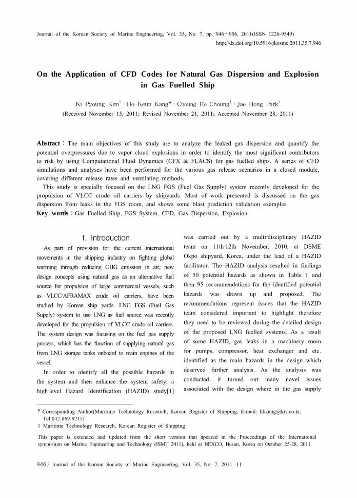
The maximum overpressure for same ignition locations is shown in Figure 8 for different scenarios on the effect of with & without obstacles. The scenario of with obstacles has 3 times higher than that of without case, and can be expected in the with obstacles scenario with overpressure peak under 0.006 barg. Hence, the obstacles do seem to play a significant role on the level of overpressures and depends strongly on its geometry such as pumps, heat exchanger, compressor and etc.
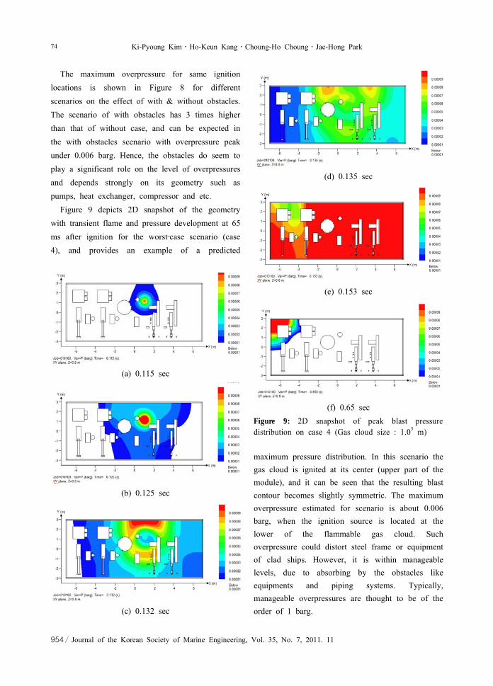
Figure 9 depicts 2D snapshot of the geometry with transient flame and pressure development at 65 ms after ignition for the worst‐case scenario (case 4), and provides an example of a predicted
(a) 0.115 sec
(b) 0.125 sec
(c) 0.132 sec
(d) 0.135 sec
(e) 0.153 sec
(f) 0.65 secFigure 9: 2D snapshot of peak blast pressure distribution on case 4 (Gas cloud size : 1.03 m)
maximum pressure distribution. In this scenario the gas cloud is ignited at its center (upper part of the module), and it can be seen that the resulting blast contour becomes slightly symmetric. The maximum overpressure estimated for scenario is about 0.006 barg, when the ignition source is located at the lower of the flammable gas cloud. Such overpressure could distort steel frame or equipment of clad ships. However, it is within manageable levels, due to absorbing by the obstacles like equipments and piping systems. Typically, manageable overpressures are thought to be of the order of 1 barg.
On the Application of CFD Codes for Natural Gas Dispersion and Explosion in Gas Fuelled Ship 75
Journal of the Korean Society of Marine Engineering, Vol. 35, No. 7, 2011. 11 / 955
The results of explosion analysis using FLACS are widely used for risk‐based design decisions, especially in the gas fuelled ships, where the space available is limited. Since the machinery spaces such as FGS room are highly confined, they can be highly congested to generate enough turbulence, resulting in significant explosion overpressure. Thus, the effect of explosion mitigation measures, like rearrangement of equipment layouts, vent openings and blast walls are important to know during the early phase of ship design. These effects can be found from CFD simulations.
4. ConclusionsAs a result of the HAZID study carried out by a
multi‐disciplinary HAZID team, “Frequent leaks in FGS room” was identified to have a high risk level among the 5 hazards in high risk level classified by the risk ranking. Therefore CFD analyses were undertaken for natural gas leaks from fuel gas supply system (FGS) room for a concept design on LNG‐fuelled VLCC recently developed by shipyard.
The dispersion study shows that the FGS room would not be at serious risk of the degree of gas filling for the leak sizes of 12.7 mm, 25.4 mm and 38.1 mm releases at 6 bar pressure. However, for the case of 50.8 mm (worst case) releases, a flammable volume in gas concentration above 50,000 ppm of the lower flammable limit was continued for 50 seconds. In current interim guideline, the required capacity of ventilation fan is normally based on the total volume of the room, and an increase in required ventilation capacity may be necessary for rooms having a complicated form like FGS room.
For the assessment of ventilating methods, the method of overpressure ventilation in the FGS room was shown a little higher efficiency than that of underpressure, in which the purging air to make turbulent was dominant.
For explosion analysis, the leak rate, gas density and ventilation are the key parameters that determine the filling degree of flammable material after accidental release. Other parameters, such as leak location and direction, also impact the filling degree. The higher filling degree of flammable material could result in higher overpressure, once the gas cloud is ignited, as shown in Fig. 7(d). It is important to design the ventilation system to effectively decrease the filling degree of flammable materials. The results of the CFD overpressure study are to be used to aid in the determination of the overpressures associated with various explosive zones, and also to evaluate the need for any structural reinforcements to existing ships due to explosive overpressure. The results of the study can be further used for detailed risk‐based design and risk analysis, as in HAZOP, which is a systemic approach adopted based on the material property and the specific geometry of the facility to effectively and accurately predict the overpressure exceedance curves.
The CFD analysis results could be applied to provide input for detailed risk‐base ship design and risk analysis, to find safe and cost‐optimal design. However, it must be kept in mind that the modeling gas dispersion/explosion is very complex and some discrepancies can be expected in certain cases, even if more and more scenarios are modeled accurately.
AcknowledgementsThis work was supported by the “LNG Plant
R&D Center” through a grant provided by the Korean Ministry of Land, Transport and Maritime Affairs (MLTM) in 2011 (Project No. 08 Gas Plant E04).
References[1] DSME, “Joint research project on LNG fueled

76 Ki-Pyoung Kim․Ho-Keun Kang․Choung-Ho Choung․Jae-Hong Park
956 / Journal of the Korean Society of Marine Engineering, Vol. 35, No. 7, 2011. 11
318,000 TWD COT”, Interim Information Release, 2010.
[2] Res.MSC.285(86), “Interim guidelines on safety for natural gas‐fuelled engine installations in ships”, IMO, 2009.
[3] ANSYS, “CFX‐12 solver theory manual”, Oxfordshire: CFX Ltd, 2010.
[4] CMR Gexcon, FLACS manual 9.1. [5] Daniel, A.C. and Joseph, F.L., “Chemical Process
Safety: Fundamentals with Applications”, Prentice Hall PTR, 1990.
[6] Hjertager, B.H., “Computer simulation of turbulent reactive gas dynamic”, Journal of Modeling Identification and Control, vol. 5, pp. 211‐236, 1985.
[7] Middha, P. and Hansen, O.R., “CFD simulation study to investigate the risk from hydrogen vehicle in tunnels”, International Journal of Hydrogen Energy, vol. 34, pp. 5875‐5886, 2009.
Author Profile
Ki-Pyoung Kim
He received his B.A. and M.S. degrees
from Korea Maritime University. He is
currently a researcher in the Department
of Maritime Technology Research Team
at Korean Register.
Ho-Keun Kang
He graduated from Korea Maritime
University(B.A. 1992 and M.S. 1997) in
Korea. He received his Ph.D degree
(2002) from Kobe University in Japan.
He is currently a senior researcher in
the Department of Maritime Technology
Research Team at Korean Register.
His interests are CFD, green ship technology, and various
energy problems including renewable energy.
Choung-Ho Choung
He received his B.A. and M.S. degrees
from Seoul National University. He is
currently a senior researcher in the
Department of Maritime Technology
Research Team at Korean Register. His
research interests include risk and
reliability assessment for offshore platform.
Jae-Hong Park
He graduated from Seoul National
University and University of Ulsan (B.A.
1985 and M.S. 1988) in Korea. He
received his Ph.D degree (2007) from
University of Southampton in England.
He is currently a principal researcher in
the Department of Maritime Technology Research Team at
Korean Register.