Embed Size (px)
Citation preview

On Structure and Suboptimality in PlacementSatoshi Ono1,2,3 Patrick H. Madden2,3
FAIS1 University of Kitakyushu2 SUNY Binghamton CSD3
Abstract— Regular structures are present in many types of cir-cuits. If this structure can be identified and utilized, performancecan be improved dramatically. In this paper, we present a novelplacement approach that successfully identifies regularity, andobtains placements that are superior to other “general purpose”methods. This method has been integrated into our Feng Shui2.6 bisection-based placement tool.
On experiments with the PEKO benchmarks, our results arewithin 32% of optimal for both the large and small suites. Thelargest example, with 2.1 million cells, can be completed in sixteenhours. The majority of our run time is during detail placement–global placement takes under three hours. The success of ourmethod shows that it can find structure, even when the structurewas not expected or intended.
As part of this work, we have made a number of observationsrelated to the nature of suboptimality in placement. Theseobservations have shown that some neglected research areashave great potential, while problems that receive considerableattention are essentially adequately solved.
I. INTRODUCTION
There has been rising interest in placement algorithms; withtechnology scaling, the importance of interconnect length onperformance continues to grow. Where in prior technologygenerations, there was only a passing interest in wire lengthminimization, this is now a key concern. Device scalingalone cannot achieve the desired performance improvements:fundamental advances in placement are needed, to reduce wirelengths, thereby reducing delay and power consumption.
Recently, a set of synthetic benchmarks were used to evalu-ate how far placement tools are from optimal, when pursuing awirelength minimization objective[5]. For the majority of toolstested, placements were significantly suboptimal: wire lengthswere from 50% to 150% higher than optimal, and the qualitygenerally degraded as circuit sizes increased. An earlier set ofexperiments on a datapath design[8] showed similar behavior;the design that was produced manually (by a designer whounderstood the structure of the circuit) was far superior to theresult produced by commercial tools.
The results reported in [8] motivated much of the workwe present here. If structure is present in a circuit, findingthe structure and then utilizing it would obviously result ina far better placement. Thus, our focus is not on a general-purpose placement method, but on one tuned for designswith internal structure. Our method can in fact find structurewhere no structure was intended or expected: for the PEKObenchmarks, we find structure, and can obtain placements thatare within 32% of optimal for both the “small” and “large”suites. Our method is also remarkably fast: global placement ofa design with 2.1 million cells is done in two and a half hours,while the complete placement run takes roughly sixteen hours.
The algorithmic complexity of our approach is O(nlogn); itis unlikely that any approach will be able to obtain betterasymptotic complexity while still producing a good qualityplacement.
The development of our approach has also resulted ina number of observations regarding the nature of optimalplacements for non-synthetic (and non-structured) designs.The PEKO benchmarks, while having a number of aspectsthat result in their being fundamentally different from “realdesigns,” have proved useful in understanding how placementmethods fail to find good solutions. We also point out a keyproblem in reaching the next level of performance: rather thanimprovements in global placement, we see the next barrierbeing detail placement. We also make observations related toarchitecture-level decisions.
The remainder of this paper is organized as follows. Wefirst discuss more traditional placement methods, and thedifferences between structured and non-structured designs. Wethen present our new approach; we assume that a structureis present in the design, and then seek to find and exploitit. Section IV presents our experimental results, with a focuson the PEKO benchmarks. Section V presents a number ofobservations, and a consideration of the quality differencebetween global placement and detail placement. We concludethe paper in Section VI.
II. PREVIOUS WORK
Circuit placement has been widely studied, and is one of theclassic problems in VLSI design. Popular methods for place-ment include annealing[16], [20], [22], analytic methods[17],[9], [14], [21], and recursive bisection[4], [15].
In each of these methods, the locations of circuit elementsare improved, to address a wire length (or weighted wirelength) minimization objective. The size of modern placementproblems makes the task difficult: with millions of componentsand wires, finding good solutions is non-trivial.
The problem is frequently divided into “global placement”and “detail placement” stages. During global placement, roughpositions are found for the components, and there may be agreat deal of overlap. The objective during global placement isto position the components close to good locations; by keepingthe positioning rough, we reduce computation time consider-ably. Additionally, the circuit can be clustered, reducing thesize and complexity of the placement problem.
During “detail placement,” overlaps are removed with le-galization techniques. Many of these techniques are based ondynamic programming (for example, [2]), although a simplegreedy method[10] has been shown to be quite effective.

Following legalization, many placement tools apply localoptimization[3] to improve results.
An implicit assumption of traditional placement is that thecircuit net list is essentially a random graph, onto whichorder must be applied. For many useful circuits, however,the arrangement of components more closely resembles amesh: both datapath designs and memories have clear “good”placements, which general purpose tools have difficulty infinding[8].
III. A NOVEL PLACEMENT ALGORITHM
The placement method we describe was developed to findstructure when structure is present. We will use “placementdistance” to mean the Manhattan distance between two cells,while “graph distance” refers to the shortest path betweenthe cells in the weighted hypergraph netlist. A fundamentalassumption of our placement approach is that there is arelationship between the placement distance between a pairof cells, and the graph distance between them.
In Figure 1, we show a graph of the physical distancebetween a pair of randomly chosen cells in a net list, versus thelength of the shortest path between them. We use the circuitPEKO01 and the placement result of mPL[5] for this figure.There is a clear correlation between physical distance (in agood quality placement) and shortest path distance.
Manhattan Distance
Distance as Degree of Net
Fig. 1. Manhattan distance in a good quality placement vs. shortest pathdistance in a weighted hypergraph.
Our tool performs placement in three steps: we first utilizegraph distances to obtain relative cell positions, then even outplacement density with cell shifting[21], and finally performlegalization and detail placement.
For determining distances in the graph, we weight thehypergraph in the following way: low cardinality nets have lowlengths, while high cardinality nets have high length. An easyway to think of this is that lower degree nets should connectcells closer together than higher degree nets do. For example,cells connected by a two-pin net are likely best placed next toeach other, while a higher degree net requires more placementarea (placement distance) to put all cells connected by the net.
We have experimented with a variety of different weightingfunctions, and discuss this briefly in the experimental resultssection.
For circuits with regular structures, the relationship betweennet degree and distance in a good placement is strong. In amesh-like topology, many nets are two-pin; adjacent elementsof the mesh are connected, with these two pin-nets being quiteshort. In a datapath circuit, bit lines and control lines arehigh-fanout, but span the height or width of the block. Aswe shall show in our experiments, there is even structure inunintended places: the synthetic PEKO benchmarks, widelyused to measure the suboptimality of placement approaches,contain a great deal of structure that our approach can detectand utilize.
Our approach uses the relationship between physical andgraph distance in the following way. If we can assume that thedistance between a pair of cells in a good placement is relatedto the degree of a net that connects them, we can use thisinformation to weight the net in a shortest-path computation.Using these weights, we can tell the maximum placementdistance of any two cells. If one of the cells is fixed in place,we can determine the placement area where the other cellcould be placed. Having more cells fixed, we have smallerarea where the movable cells could be placed.
Buffer insertion and clock tree generation algorithms (forexample, [13], [7]) use similar principles: given the location ofa buffer or clock driver, there is a “feasible region” in whichanother buffer or driver might be placed. The intersectionsof these regions are used to determine locations for otherelements. The princple is also similar to techniques used inglobal positioning and radar systems: the location an objectcan be determined based on distances from reference points.We refer to our placement tool as “beacon,” as much ofour placement approach is modeled around a GPS system–satellites act as signal beacons, providing reference points fortriangulation.
Steps in our approach are the following.• We identify good candidates for “corner” cells, and fix
them in place.• We determine the distance of every other cell from the
placed corners, using the relationship between placementdistance and graph distance.
• From each corner, the possible location for the placementof a cell is a Manhattan circle (diamond). The inter-sections of these circles for a given cell determine thepossible locations for placement.
• Each cell is placed in the center of it’s correspondingManhattan circle; we then apply cell shifting, traditionallegalization, and detail placement.
Corner FindingWhen pads are present, finding a “corner” is trivial; for
benchmarks which do not have pads, we perform the followingsteps.
We first pick one cell randomly, then run the Dijkstra’salgorithm with the net weights to find the farthest cell fromthe random chosen cell. We assume the farthest cell, A, is one

of the corners. Next, we run Dijkstra’s algorithm starting fromcell A, and we set the farthest cell, B, as the diagonal corner.Using the same technique, but with cells A and B as sources,we identify the third corner, C. With the source cell as C, wefind the fourth corner, D. Depending on the ratio A to C and Ato D, we chose a configuration that gives acceptable distanceratios, and have determined four “corner” cells. The locationsof these cells are fixed at the corners of the placement region,and these four become the “beacons” that are used in the restof our placement approach.
Triangulation
Using the graph distance from four corners, we place theremainder of the cells. We run Dijkstra’s algorithm four times–once from each of the four corners. Dijkstra’s algorithm givesdistances to all cells–for each cell, we have four distances,and we use these to triangulate the possible locations for thecell. Again, the principle is similar to methods commonly inuse with buffer insertion and clock tree generation.
Cell Shifting
In Figure 2, we show the shape of the placement prior tolegalization. As graph distance is not exactly equal to physicaldistance, there can be overlap, resulting in higher density inthe center of the placement region.
To remove overlap, we apply the “cell shifting” techniquepresented in [21]. The placement area is divided into horizontalor vertical stripes, and then by applying iterative bin adjust-ments, the cells are evenly distributed across the placementregion, while relative positions are kept in tact. Figure 2 alsoshows wire length changes during placement shifting by colorcoding the cells.
The color coding uses the following scheme: as the PEKObenchmarks have known optimal configurations, we know thetotal length of nets connected to any given cell in an optimalplacement. We compare the net lengths in this ideal case tothe lengths for each cell in our placement: higher lengths areshaded a darker color, allowing easy visualization of placementquality. From the figure, it is easy to see that prior to cellshifting, net lengths are quite close to their optimal values.After shifting, lengths increase slightly, but are still close tothe desired values.
Legalization and Detailed Placement
Our approach is integrated with our Feng Shui 2.6[2] tool,and we use this to perform legalization and detail placement.Version 2.6 provides a simple greedy heuristic based on[10], and branch-and-bound driven detail placement. In ourexperiments, we include run times for both the “beacon”portion of a run, and the time consumed by detail placement.Run times are in fact dominated by detail placement, withglobal placement contributing only around 25% of the totalrun time.
In the experiments we report here, the detail placementwindow uses a size of 4; increasing the size of the windowimproves results slightly, with an increase in run time.
Shape of Beacon Placement Shape after Cell Shifting
Wirelength Diffrence fron Opt. of Beacon Placement
Wirelength Diffrence from Opt.after Cell Shifting
Fig. 2. Cell shifting, evening cell density across the placement region. Cellsare color coded based on the lengths of connected nets.
IV. EXPERIMENTAL RESULTS
For our experiments, we have tried a variety of net weight-ing schemes. We find that for designs with regularity, anextremely simple method works quite well: we equate hyper-graph edge length to the cardinality of a net minus 1 (scaledfor cell size). Thus, a two pin net has a length of “1”, a threepin net “2,” and so on.
To evaluate the performance of our placement approach,we first applied it to regular mesh structures. Not surpris-ingly, results were quite good. For a more interesting andchallenging test, we next considered the PEKO benchmarkcircuits[5]; these have been widely used to evaluate placementperformance, have known optimal configurations, and are largeenough to test the scalability of placement tools.
In Tables I and II, we show the run times of differentportions of our placement approach on PEKO suite 1 and 2.The largest design contains roughly 2.1 million cells, and canbe completed on a 2.4ghz Pentium-based PC running Linux,in roughly sixteen hours. The bulk of the run time is consumedby detail placement.
In Table III, we compare quality ratios of a number ofcurrent academic and commercial tools on both PEKO suite 1and 2. We use some results reported in [5]–many of the toolshave new versions, with improved results. Most placementtools are at least 50% away from optimal in terms of wirelength, with quality degrading as the problem sizes increase.Run time and memory become an issue with the largerbenchmarks. Direct run time comparisons are not possible,due to differences in the computing platforms.
Our tool is able to complete all designs in less than 24 hours.
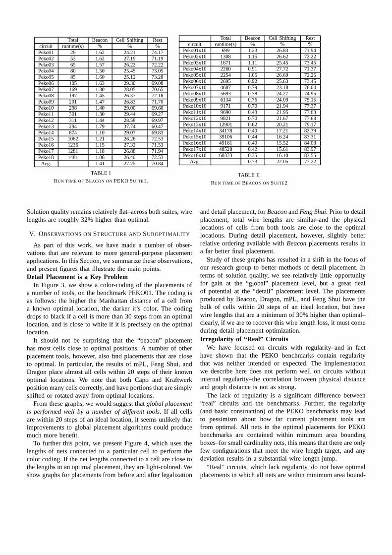
Total Beacon Cell Shifting Restcircuit runtime(s) % % %Peko01 29 1.62 24.21 74.17Peko02 53 1.62 27.19 71.19Peko03 65 1.57 26.22 72.22Peko04 80 1.50 25.45 73.05Peko05 85 1.60 25.12 73.28Peko06 105 1.63 29.30 69.08Peko07 169 1.30 28.05 70.65Peko08 197 1.45 26.37 72.18Peko09 201 1.47 26.83 71.70Peko10 298 1.40 29.00 69.60Peko11 301 1.30 29.44 69.27Peko12 311 1.44 28.58 69.97Peko13 294 1.79 37.74 60.47Peko14 874 1.10 29.07 69.83Peko15 1062 1.21 26.26 72.53Peko16 1236 1.15 27.32 71.53Peko17 1281 1.18 26.88 71.94Peko18 1481 1.06 26.40 72.53
Avg. 1.41 27.75 70.84
TABLE I
RUN TIME OF BEACON ON PEKO SUITE1.
Total Beacon Cell Shifting Restcircuit runtime(s) % % %
Peko01x10 699 1.23 26.83 71.94Peko02x10 1308 1.15 26.62 72.22Peko03x10 1671 1.11 25.45 73.45Peko04x10 2260 0.91 27.72 71.37Peko05x10 2254 1.05 26.69 72.26Peko06x10 2695 0.92 25.63 73.45Peko07x10 4687 0.79 23.18 76.04Peko08x10 5693 0.78 24.27 74.95Peko09x10 6134 0.76 24.09 75.15Peko10x10 9171 0.70 21.94 77.37Peko11x10 9690 0.43 21.95 77.63Peko12x10 9821 0.70 21.67 77.63Peko13x10 12901 0.62 20.21 79.17Peko14x10 34178 0.40 17.21 82.39Peko15x10 39106 0.44 16.24 83.31Peko16x10 49161 0.40 15.52 84.08Peko17x10 48528 0.42 15.61 83.97Peko18x10 60373 0.35 16.10 83.55
Avg. 0.73 22.05 77.22
TABLE II
RUN TIME OF BEACON ON SUITE2
Solution quality remains relatively flat–across both suites, wirelengths are roughly 32% higher than optimal.
V. OBSERVATIONS ON STRUCTURE AND SUBOPTIMALITY
As part of this work, we have made a number of obser-vations that are relevant to more general-purpose placementapplications. In this Section, we summarize these observations,and present figures that illustrate the main points.Detail Placement is a Key Problem
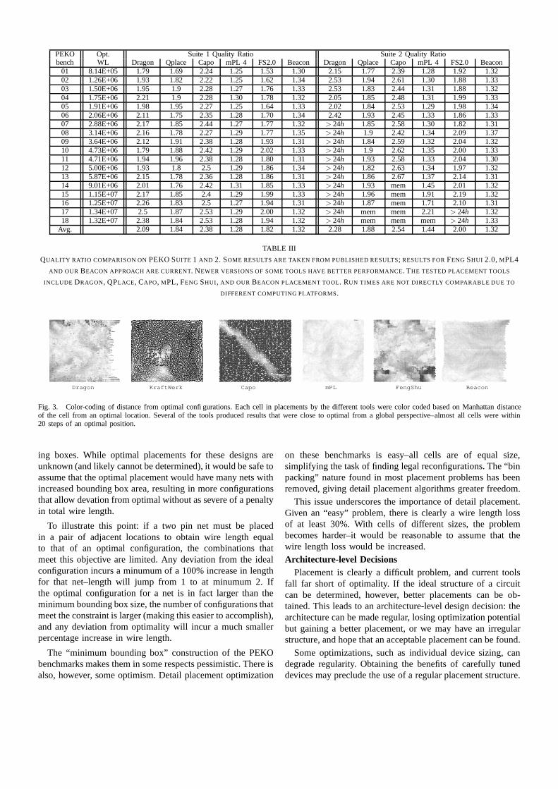
In Figure 3, we show a color-coding of the placements ofa number of tools, on the benchmark PEKO01. The coding isas follows: the higher the Manhattan distance of a cell froma known optimal location, the darker it’s color. The codingdrops to black if a cell is more than 30 steps from an optimallocation, and is close to white if it is precisely on the optimallocation.
It should not be surprising that the “beacon” placementhas most cells close to optimal positions. A number of otherplacement tools, however, also find placements that are closeto optimal. In particular, the results of mPL, Feng Shui, andDragon place almost all cells within 20 steps of their knownoptimal locations. We note that both Capo and Kraftwerkposition many cells correctly, and have portions that are simplyshifted or rotated away from optimal locations.
From these graphs, we would suggest that global placementis performed well by a number of different tools. If all cellsare within 20 steps of an ideal location, it seems unlikely thatimprovements to global placement algorithms could producemuch more benefit.
To further this point, we present Figure 4, which uses thelengths of nets connected to a particular cell to perform thecolor coding. If the net lengths connected to a cell are close tothe lengths in an optimal placement, they are light-colored. Weshow graphs for placements from before and after legalization
and detail placement, for Beacon and Feng Shui. Prior to detailplacement, total wire lengths are similar–and the physicallocations of cells from both tools are close to the optimallocations. During detail placement, however, slightly betterrelative ordering available with Beacon placements results ina far better final placement.
Study of these graphs has resulted in a shift in the focus ofour research group to better methods of detail placement. Interms of solution quality, we see relatively little opportunityfor gain at the “global” placement level, but a great dealof potential at the “detail” placement level. The placementsproduced by Beacon, Dragon, mPL, and Feng Shui have thebulk of cells within 20 steps of an ideal location, but havewire lengths that are a minimum of 30% higher than optimal–clearly, if we are to recover this wire length loss, it must comeduring detail placement optimization.Irregularity of “Real” Circuits
We have focused on circuits with regularity–and in facthave shown that the PEKO benchmarks contain regularitythat was neither intended or expected. The implementationwe describe here does not perform well on circuits withoutinternal regularity–the correlation between physical distanceand graph distance is not as strong.
The lack of regularity is a significant difference between“real” circuits and the benchmarks. Further, the regularity(and basic construction) of the PEKO benchmarks may leadto pessimism about how far current placement tools arefrom optimal. All nets in the optimal placements for PEKObenchmarks are contained within minimum area boundingboxes–for small cardinality nets, this means that there are onlyfew configurations that meet the wire length target, and anydeviation results in a substantial wire length jump.
“Real” circuits, which lack regularity, do not have optimalplacements in which all nets are within minimum area bound-
PEKO Opt. Suite 1 Quality Ratio Suite 2 Quality Ratiobench WL Dragon Qplace Capo mPL 4 FS2.0 Beacon Dragon Qplace Capo mPL 4 FS2.0 Beacon
01 8.14E+05 1.79 1.69 2.24 1.25 1.53 1.30 2.15 1.77 2.39 1.28 1.92 1.3202 1.26E+06 1.93 1.82 2.22 1.25 1.62 1.34 2.53 1.94 2.61 1.30 1.88 1.3303 1.50E+06 1.95 1.9 2.28 1.27 1.76 1.33 2.53 1.83 2.44 1.31 1.88 1.3204 1.75E+06 2.21 1.9 2.28 1.30 1.78 1.32 2.05 1.85 2.48 1.31 1.99 1.3305 1.91E+06 1.98 1.95 2.27 1.25 1.64 1.33 2.02 1.84 2.53 1.29 1.98 1.3406 2.06E+06 2.11 1.75 2.35 1.28 1.70 1.34 2.42 1.93 2.45 1.33 1.86 1.3307 2.88E+06 2.17 1.85 2.44 1.27 1.77 1.32 > 24h 1.85 2.58 1.30 1.82 1.3108 3.14E+06 2.16 1.78 2.27 1.29 1.77 1.35 > 24h 1.9 2.42 1.34 2.09 1.3709 3.64E+06 2.12 1.91 2.38 1.28 1.93 1.31 > 24h 1.84 2.59 1.32 2.04 1.3210 4.73E+06 1.79 1.88 2.42 1.29 2.02 1.33 > 24h 1.9 2.62 1.35 2.00 1.3311 4.71E+06 1.94 1.96 2.38 1.28 1.80 1.31 > 24h 1.93 2.58 1.33 2.04 1.3012 5.00E+06 1.93 1.8 2.5 1.29 1.86 1.34 > 24h 1.82 2.63 1.34 1.97 1.3213 5.87E+06 2.15 1.78 2.36 1.28 1.86 1.31 > 24h 1.86 2.67 1.37 2.14 1.3114 9.01E+06 2.01 1.76 2.42 1.31 1.85 1.33 > 24h 1.93 mem 1.45 2.01 1.3215 1.15E+07 2.17 1.85 2.4 1.29 1.99 1.33 > 24h 1.96 mem 1.91 2.19 1.3216 1.25E+07 2.26 1.83 2.5 1.27 1.94 1.31 > 24h 1.87 mem 1.71 2.10 1.3117 1.34E+07 2.5 1.87 2.53 1.29 2.00 1.32 > 24h mem mem 2.21 > 24h 1.3218 1.32E+07 2.38 1.84 2.53 1.28 1.94 1.32 > 24h mem mem mem > 24h 1.33
Avg. 2.09 1.84 2.38 1.28 1.82 1.32 2.28 1.88 2.54 1.44 2.00 1.32
TABLE III
QUALITY RATIO COMPARISON ON PEKO SUITE 1 AND 2. SOME RESULTS ARE TAKEN FROM PUBLISHED RESULTS; RESULTS FOR FENG SHUI 2.0, MPL4
AND OUR BEACON APPROACH ARE CURRENT. NEWER VERSIONS OF SOME TOOLS HAVE BETTER PERFORMANCE. THE TESTED PLACEMENT TOOLS
INCLUDE DRAGON, QPLACE, CAPO, MPL, FENG SHUI, AND OUR BEACON PLACEMENT TOOL. RUN TIMES ARE NOT DIRECTLY COMPARABLE DUE TO
DIFFERENT COMPUTING PLATFORMS.
Dragon KraftWerk Capo mPL FengShu Beacon
Fig. 3. Color-coding of distance from optimal configurations. Each cell in placements by the different tools were color coded based on Manhattan distanceof the cell from an optimal location. Several of the tools produced results that were close to optimal from a global perspective–almost all cells were within20 steps of an optimal position.
ing boxes. While optimal placements for these designs areunknown (and likely cannot be determined), it would be safe toassume that the optimal placement would have many nets withincreased bounding box area, resulting in more configurationsthat allow devation from optimal without as severe of a penaltyin total wire length.
To illustrate this point: if a two pin net must be placedin a pair of adjacent locations to obtain wire length equalto that of an optimal configuration, the combinations thatmeet this objective are limited. Any deviation from the idealconfiguration incurs a minumum of a 100% increase in lengthfor that net–length will jump from 1 to at minumum 2. Ifthe optimal configuration for a net is in fact larger than theminimum bounding box size, the number of configurations thatmeet the constraint is larger (making this easier to accomplish),and any deviation from optimality will incur a much smallerpercentage increase in wire length.
The “minimum bounding box” construction of the PEKObenchmarks makes them in some respects pessimistic. There isalso, however, some optimism. Detail placement optimization
on these benchmarks is easy–all cells are of equal size,simplifying the task of finding legal reconfigurations. The “binpacking” nature found in most placement problems has beenremoved, giving detail placement algorithms greater freedom.
This issue underscores the importance of detail placement.Given an “easy” problem, there is clearly a wire length lossof at least 30%. With cells of different sizes, the problembecomes harder–it would be reasonable to assume that thewire length loss would be increased.Architecture-level Decisions
Placement is clearly a difficult problem, and current toolsfall far short of optimality. If the ideal structure of a circuitcan be determined, however, better placements can be ob-tained. This leads to an architecture-level design decision: thearchitecture can be made regular, losing optimization potentialbut gaining a better placement, or we may have an irregularstructure, and hope that an acceptable placement can be found.
Some optimizations, such as individual device sizing, candegrade regularity. Obtaining the benefits of carefully tuneddevices may preclude the use of a regular placement structure.

FengShui 2.0 Global Placed: WL 1429056 FengShui 2.0 Detail Placed: WL 1233152
Beacon Global Placed: WL 1465216 Beacon 2.0 Detail Placed: WL 1044288
Fig. 4. Wire length difference from optimal before and after detail placement.
Without the structure, there is the inherent performance losscaused by the difficulty of placement.
The rise in interest in “fabric-based” design (for exam-ple [6], [11], [19]) reflects these issues. By mapping anarchitecture onto a regular structure, we lose optimizationpotential, but gain far better placement results. In [12], it wassuggested that regular layouts were not required–with the risein interconnect delay, and the clear suboptimality of irregularcircuit placement, this may no longer be the case.
VI. CONCLUSION AND FUTURE WORK
Over the past few years, there have been great ad-vances in placement research. A convergence on metrics andbenchmarks[18], [1] has allowed direct comparison of results.The PEKO benchmarks[5] showed how far current tools werefrom optimal, and how much performance gain was possiblethrough better placement.
In this work, we have presented a placement approach thatfinds and exploits structure in circuits. We use the strongrelationship between physical distance and graph distance todevelop a new method that works exceptionally well on awidely used set of benchmarks. While the PEKO benchmarksmay not accurately reflect “real” circuits, and results havea mix of optimism and pessimism, their impact on researchfocus has been profound.
Our experiments have also highlighted an important prob-lem in physical design: detail placement, perhaps consideredeffectively “solved,” is clearly responsible for a large percent-age of the optimality gap on modern placements. Improvingdetail placement methods is essential to reaching the nextplateau of performance.
Current work in our group focuses on detail placement, andon finding “good” lengths for nets in netlists which do nothave regular structure. Preliminary experiments indicate thatour “beacon” approach can be extended to a wider class of
circuits, while maintaining the speed and quality which wehave obtained on regular circuits. Details of this work will bepresented when it is mature.Acknowledgements: This work was supported in part byan IBM Faculty Partnership Award, SRC Project 947.1, anequipment grant from Intel, NYSTAR MDC, and by fundsfrom the Japanese Ministry of ECSST via Kitakyushu andFukuoka knowledge-based cluster project.
REFERENCES
[1] S. N. Adya, M. C. Yildiz, I. L. Markov, P. G. Villarrubia, P. N. Parakh,and P. H. Madden. Benchmarking for large-scale placement and beyond.In Proc. Int. Symp. on Physical Design, pages 95–103, 2003.
[2] A. Agnihotri, M. C. Yildiz, A. Khatkhate, A. Mathur, S. Ono, and P. H.Madden. Fractional cut: Improved recursive bisection placement. InProc. Int. Conf. on Computer Aided Design, pages 307–310, 2003.
[3] A. E. Caldwell, A. B. Kahng, and I. L. Markov. Optimal partitionersand end-case placers for standard cell layout. In Proc. Int. Symp. onPhysical Design, pages 90–96, 1999.
[4] A. E. Caldwell, A. B. Kahng, and I. L. Markov. Can recursive bisectionalone produce routable placements? In Proc. Design Automation Conf,pages 477–482, 2000.
[5] C. C. Chang, J. Cong, and M. Xie. Optimality and scalability studyof existing placement algorithms. In Proc. Asia South Pacific DesignAutomation Conf., pages 621–627, 2003.
[6] J. Cong, Y. Fan, X. Yang, and Z. Zhang. Architecture and syntehsisfor multi-cycle communication. In Proc. Int. Symp. on Physical Design,pages 190–196, 2003.
[7] J. Cong and C.-K. Koh. Interconnect layout optimization under higher-order RLC model. In Proc. Int. Conf. on Computer Aided Design, pages713–720, 1997.
[8] W. J. Dally and A. Chang. The role of custom design in ASIC chips.In Proc. Design Automation Conf, pages 643–647, 2000.
[9] H. Eisenmann and F. M. Johannes. Generic global placement andfloorplanning. In Proc. Design Automation Conf, pages 269–274, 1998.
[10] D. Hill. US patent 6,370,673: Method and system for high speed detailedplacement of cells within an integrated circuit design, 2002.
[11] B. Hu, H. Jiang, Q. Liu, and M. Marek-Sadowska. Synthesis andplacement flow for gain-based programmable regular fabrics. In Proc.Int. Symp. on Physical Design, pages 197–203, 2003.
[12] P. Ienne and A. Griessing. Practical experiences with standard-cell baseddatapath design tools: do we really need regular layouts? In Proc. DesignAutomation Conf, pages 396–401, 1998.
[13] A. B. Kahng and C.-W. A. Tsao. Low-cost single-layer clock trees withexact zero Elmore delay skew. In Proc. Int. Conf. on Computer AidedDesign, pages 213–218, 1994.
[14] A. B. Kahng and Q. Wang. Implementation and extensibility of ananalytic placer. In Proc. Int. Symp. on Physical Design, pages 18–25,2004.
[15] A. Khatkhate, C. Li, A. R. Agnihotri, M. C. Yildiz, S. Ono, C.-K. Koh,and P. H. Madden. Recursive bisection based mixed block placement.In Proc. Int. Symp. on Physical Design, pages 84–89, 2004.
[16] S. Kirkpatrick, C. D. Gelatt, and M. P. Vecchi. Optimization bysimulated annealing. Science, 220(4598):671–680, May 1983.
[17] J. Kleinhans, G. Sigl, F. Johannes, and K. Antreich. GORDIAN: VLSIplacement by quadratic programming and slicing optimization. IEEETrans. on Computer-Aided Design of Integrated Circuits and Systems,10(3):356–365, 1991.
[18] P. H. Madden. Reporting of standard cell placement results. IEEETrans. on Computer-Aided Design of Integrated Circuits and Systems,21(2):240–247, February 2002.
[19] D. D. Sherlekar. Design considerations for regular fabrics. In Proc. Int.Symp. on Physical Design, pages 97–102, 2004.
[20] W. Swartz and C. Sechen. Timing driven placement for large standardcell circuits. In Proc. Design Automation Conf, pages 211–215, 1995.
[21] N. Viswanathan and C. C.-N. Chu. Fastplace: Efficient analyticalplacement using cell shifting, iterative local refinement and a hybridnet model. In Proc. Int. Symp. on Physical Design, pages 26–33, 2004.
[22] M. Wang, X. Yang, and M. Sarrafzadeh. Dragon2000: Standard-cellplacement tool for large industry circuits. In Proc. Int. Conf. onComputer Aided Design, pages 260–263, 2000.