Embed Size (px)
Citation preview

April 2013
On-site Wastewater
Systems Code
Foreword
The Department for Health and Ageing (DHA) On-site Wastewater Systems Code (The Code) has been developed pursuant to the provisions of the South Australian Public Health Act 2011 (SAPH Act) and the regulations made under that Act dealing with wastewater (Wastewater Regulations). The SAPH Act requires the DHA and the South Australian Public Health Council (SAPHC) to keep public health legislation under review for the purpose of accommodating changing community needs and practices, facilitating the day-to-day administration of the legislation and protecting public health.
This Code replaces “Waste control systems, standard for the construction, installation and operation of septic tank systems in South Australia” and its supplements. The Wastewater Regulations and the DHA wastewater codes have been formulated to reflect changes associated with current trends in wastewater management practices.
Policies and guidelines relating to on-site wastewater systems and connection of wastewater systems to community wastewater management systems (CWMS) have been in existence since the late 1980s.
This Code has been compiled to assist the relevant authorities with processing applications for approval of on-site wastewater products and installations, and connections of wastewater products to a CWMS. It also provides information to assist manufacturers, designers, local councils, consultants, industry, property owners and occupiers on:
> The requirements to be considered in the planning stages of on-site wastewater systems
> The requirements for design of on-site wastewater systems
> The requirements for approval of on-site wastewater products
> The technical requirements for connection to a CWMS.
It should be noted that this document is a prescribed code under the Wastewater Regulations. It needs to be read in conjunction with the Wastewater Regulations, the relevant Australian and New Zealand Standards and other appropriate prescribed codes.
On-site Wastewater Systems Code April 2013
Foreword
Contents
Glossary and Terms 1
1 Introduction 6
1.1 Scope 6
1.2 Changes to existing systems 6
1.3 Permanent greywater systems 6
1.4 Relevant Australian/New Zealand
Standards 6
1.5 Trade waste requirements 7
1.5.1 On-site systems 7
1.5.2 CWMS connections 7
1.6 CWMS design, construction
and operation 7
2 Information and Enquiries 8
3 Legal Requirements/Applications 9
3.1 South Australian Public Health Act 2011 9
3.2 Wastewater Regulations 9
3.3 Local Government Act 1999 9
3.4 Other Acts and regulations 9
3.5 Wastewater works approvals 9
3.6 Application for wastewater
works approval 9
3.6.1 On-site wastewater systems 10
3.6.2 CWMS connections 11
3.6.3 Permanent greywater systems 12
3.6.4 Trade waste discharges 12
3.7 Planning requirements 13
3.8 Sites, buildings under separate ownership 13
3.8.1 On-site wastewater systems 13
3.8.2 Areas served by a CWMS 13
4 Plumbing, Drainage and Installation 14
4.1 Inspection requirements 14
4.2 Installation 14
4.3 Certificates of Compliance 14
4.4 Connection to a CWMS
– older premises 14
4.5 Independent certification 14
4.6 Durable notice 15
4.7 Surface or subsurface water diversion 15
4.8 Systems to be installed in areas
administered by water industry entities 15
4.9 Commissioning and inspection 15
On-site Wastewater Systems Code April 2013 page (i)
Contents
5 Design Flows and Capacities 16
5.1 Minimum capacity 16
5.2 Hydraulic capacity 16
5.2.1 Design flows 16
5.2.2 Prohibited discharges 17
5.2.3 Determination of primary
treatment/septic tank capacity 17
5.2.4 Connection to a CWMS
– use of existing primary
treatment/septic tanks 18
5.3 Organic capacity 18
5.4 Non-standard fixtures 18
5.4.1 Spa baths and food waste
disposal units 18
5.4.2 Commercial kitchens 19
5.4.3 Commercial and other premises
with on-site systems 19
6 Treatment Systems 20
6.1 Septic tanks 20
6.2 Aerated wastewater treatment
systems 20
6.3 Aerobic sand filters 20
6.4 Reed beds 20
6.5 Composting toilets 20
7 Ancillary Structures 21
7.1 Access and inspection openings 21
7.2 Pump sumps and pumps 21
7.3 Vacuum collection chambers 21
7.4 Distribution sumps 21
7.5 Holding tanks 21
8 Land Application Systems 22
8.1 Introduction 22
8.2 Site and soil assessment 22
8.2.1 Wastewater engineer’s report 22
8.2.2 Site characteristics 24
8.3 Subsurface effluent disposal systems 25
8.3.1 System sizing 25
8.3.2 Subsurface disposal system
construction 27
8.3.3 Soakage trenches 28
8.3.4 Soakage bed 28
8.3.5 Diversion trench 29
8.4 Surface irrigation systems 29
8.4.1 Recycled water quality
requirements 29
8.4.2 Sizing of the irrigation area 29
8.4.3 Irrigation area requirements 30
8.4.4 Irrigation system requirements 31
8.4.5 Recreational area requirements 32
8.5 Shallow subsurface irrigation 32
On-site Wastewater Systems Code April 2013
Contents
page (ii)
9 Use of AS/NZS 1547 On-site domestic wastewater management in South Australia 33
9.1 Australian/New Zealand
Standard 1547 (AS/NZS 1547) 33
9.2 State amendments 33
9.2.1 Hydraulic loadings and products 33
9.2.2 Setback distances 33
9.2.3 Construction and installation 33
9.2.4 Other 33
9.3 Deemed to satisfy 33
10 Off-site Disposal 33
10.1 Community wastewater
management systems (CWMS) 34
10.2 Holding tanks 34
10.2.1 New land divisions 34
10.2.2 Existing allotments 34
10.2.3 Design, installation and
performance requirements 34
11 Operation and Maintenance 35
11.1 General 35
11.2 Operation and maintenance manuals 35
11.3 Maintenance and servicing 35
11.3.1 Owners/operators 35
11.3.2 Relevant authority 35
11.3.3 Primary treatment tank/septic 35
tank sludge disposal
11.3.4 Holding tank wastewater disposal 35
11.4 Service providers 36
11.4.1 Availability of service 36
11.5 Inspection and monitoring programs 36
11.6 Septic tank desludging 36
11.7 Maintenance of on-site wastewater
systems connected to a CWMS 36
12 Product Approvals 37
12.1 On-site wastewater systems covered by
Australian Standards 37
12.1.1 Legislation 37
12.1.2 Application procedure 37
12.1.3 Product certification 37
12.1.4 Application requirements 38
12.2 Systems not covered by an
Australian/New Zealand Standard 39
12.2.1 Legislation 39
12.2.2 Product approval procedure 39
12.2.3 Product certification 39
12.2.4 Application criteria 40
12.2.5 Existing interstate or
overseas approvals 40
12.2.6 Recycled water compliance criteria 40
12.2.7 Design requirements 40
12.3 Permanent greywater systems 41
On-site Wastewater Systems Code April 2013 page (iii)
Contents

Appendix A – A1: Typical site layout plan 42
A2: Typical building layout plan 43
A3: Typical site layout plan –
two tank system and split
irrigation area 44
A4: Typical greywater subsurface
trench system 45
A5: Typical greywater subsurface
drip irrigation system 46
A6: Typical building layout plan
for sewage and greywater
on-site wastewater treatment
systems 47
A7: Typical horizontal septic
tank design 48
A8: Soakage trench - typical tunnel
system 49
A9: Soakage trench - typical
perforated pipe system 50
A10: Typical distribution sump/
trench layout 51
A11: Typical diversion and soakage
trench section 52
A12: Typical layout utilising
a diversion trench 53
A13: Typical soakage bed 54
A14: Typical site layout plan
for an aerated wastewater
treatment system and
surface irrigation 55
A15: Typical site layout plan showing
STEDS connection details for
an all wastewater septic
tank system 56
A16: Typical site layout showing
STEPS connection details 57
A17: Typical sewer connection 58
A18: Typical pressure sewerage
system connection details 59
A19: Typical vacuum sewerage
collection chamber
(DN 1050) details 60
A20: Typical pump and pump
chamber detail 61
Appendix B – Setback Distances 62
Appendix C – On-site Domestic Greywater Systems 66
Appendix D – Suitable Plants for
Recycled Water Irrigation 67
Appendix E – Hydraulic and BOD5 Loadings 70
Appendix F – Connection of the Property
Wastewater System to a CWMS 79
Appendix G – Dual Water Supply Systems
for Premises 87
On-site Wastewater Systems Code April 2013
Contents
page (iv)

Glossary and Terms
Aerated wastewater treatment system (AWTS)
A system which uses the processes of aeration followed by clarification to achieve biological treatment of wastewater.
Aerobic sand filter A system that treats effluent by filtration and subsequent oxidation by aerobic and nitrifying organisms.
Air admittance valve A valve designed to allow entry of air into the plumbing and drainage system when negative pressures occur.
All wastewater The combined blackwater and greywater from a dwelling or premises.
AS/NZS Australian/New Zealand Standard (latest version).
Blackwater Wastewater discharged from either a toilet or urinal.
BOD5 (biochemical oxygen demand)
The measurement of dissolved oxygen used by microorganisms in the biochemical oxidation of organic matter over a 5 day period.
Bore See well.
Building A building as classified under the provisions of the Development Act 1993; or building work requiring Development Act Approval; or as defined in the South Australian Public Health Act 2011.
Coast As defined by the Coast Protection Act 1972, all land that is:
(a) within the mean high water mark and the mean low water mark on the seashore at spring tides; or
(b) above and within one hundred metres of that mean high water mark; or(c) below and within three nautical miles of that mean low water mark; or (d) within any estuary, inlet, river, creek, bay or lake and subject to the ebb and
flow of the tide; or(e) declared by regulation to constitute part of the coast for the purposes of the
Coast Protection Act (1972).1
See also mean high water springs.
1 Coast Protection (region) Regulations 2000. The regions are: Eyre, Fleurieu, Kangaroo Island, Metropolitan, South East, Spencer, Yorke
Community wastewater management system (CWMS)
As defined by the Wastewater Regulations:
a system for the collection and management of wastewater generated in a town, regional area or other community, but does not include –(a) SA Water sewerage infrastructure; or(b) after 1 July 2015–a system with a capacity that exceeds 2000 EP.
Composting toilet (waterless)
A device that receives and treats human excreta, domestic organic matter and bulking agents, using natural aerobic stabilisation and disinfection processes to produce a product that is not a public health risk.
Daily flow The wastewater volume flowing into the wastewater system during a 24 hour period. Also see hydraulic loading.
Desludging Removal of accumulated sludge and scum from a septic tank, other treatment system, pump sump or holding tank.
Disinfection Wastewater treatment method which kills or inactivates microbial pathogens to an acceptable level, satisfactory for the intended use. Its effectiveness is typically measured by the reduction in faecal indicator bacteria E. coli.
Effluent The liquid discharged from a wastewater treatment system.
Equivalent persons (EP) One equivalent person for the purpose of this Code is rated as 150 litres flow per day and 70 grams BOD5 per day (sewage).
On-site Wastewater Systems Code April 2013 page 1
Glossary and Terms
Escherichia coli (E. coli) A member of the faecal coliform group of bacteria and indicator of faecal contamination.
Greywater The domestic wastewater from baths, showers, basins, laundries and kitchen sinks/dishwashers specifically excluding water closet and urinal wastes. Also see wastewater.
Groundwater The body of water in the soil, all the pores of which are saturated with water. If the body of water is present at all times it represents permanent or true groundwater.
Holding tank A tank or vessel used for the temporary containment of wastewater prior to approved disposal.
Hydraulic loading Liquid flow required to be handled by the wastewater system. Also see daily flow.
Infrastructure That part of the CWMS under the care and control of the relevant authority and includes the connection point provided to each property.
JAS-ANZ Joint Accreditation System of Australia and New Zealand.
Land application system
The system used to apply effluent from a wastewater treatment system into or onto the soils for further in soil treatment and soakage/reuse.
Land division As defined by The Development Act 1993, division of an allotment means –
(a) the division, subdivision or resubdivision of the allotment (including by community plan under the Community Titles Act 1996 and by strata plan under the Strata Titles Act 1988); or
(b) the alteration of the boundaries of an allotment; or(c) the conferral or exercise of a present right to occupy part only of an allotment under
a lease or licence, or an agreement for a lease or licence, the term of which exceeds six years or such longer term as may be prescribed, or in respect of which a right or option of renewal or extension exists so that the lease, licence or agreement may operate by virtue of renewal or extension for a total period exceeding six years or such longer period as may be prescribed;or
(d) the grant or acceptance of a lease or licence, or the making of an agreement for a lease or licence, of a class prescribed by regulation,
and to divide has a corresponding meaning.
Mean high water springs
The level that is the average of all twice-daily high tides at spring periods.
The Minister The Minister of the Crown to whom the administration of the South Australian Public Health Act is for the time being committed (the Minister for Health and Ageing).
On-site wastewater system
As defined by the Wastewater Regulations:
(1) An on-site wastewater system is a system used on premises for the on-site collection and management of wastewater generated at the premises where –
(a) the wastewater collected and managed is predominantly – (i) human waste either alone or in combination with water; or (ii) water that has been used in washing, laundering, bathing or showering; or (iii) water containing food or beverage waste; or (iv) a combination of the above; and
(b) some or all of the wastewater is reused or disposed of by means other than disposal to a CWMS or to SA Water sewerage infrastructure and includes any associated irrigation or other system for the disposal of the wastewater on land other than that from which the wastewater is collected.(2) An on-site wastewater system includes (but is not limited to) a septic tank, waterless
composting toilet, or an aerated wastewater treatment system, to which AS/NZS 1546 applies.
(3) An on-site wastewater system may, but need not, be connected to a CWMS or to SA Water sewerage infrastructure.
On-site Wastewater Systems Code April 2013
Glossary and Terms
page 2

Pressure sewerage system (PSS)
A type of CWMS in which macerated sewage is conveyed under pressure generated by pumping units located on each property to a sewage treatment facility or another sewerage system.
Pre-treatment Removal of pollutants from wastewater so as to make it suitable for discharge to a wastewater system.
Primary treatment The separation of suspended material from wastewater in septic tanks, primary settling chambers etc. prior to effluent discharge to a CWMS, secondary treatment process or to a land application system.
Prohibited substance > Substances (such as fibrous material, large solid particles, materials likely to polymerise) that could block or otherwise be detrimental to the operation of the wastewater system.
> Substances (such as volatile solvents) that could generate hazardous gases or vapours in the wastewater system.
> Chlorinated hydrocarbons.> Discrete oil or other materials that are immiscible with water.> Any other substance or matter not permitted to be discharged to the wastewater
system by the relevant authority.
Property connecting drains or apparatus
Any part of a wastewater system located on private or public property/ premises that is under the care and control of the property owner, occupier of the premises or other agency and is deemed by the relevant authority not to be part of the CWMS infrastructure.
Recycled water Water which has been derived from a wastewater system and treated to a standard that is appropriate for its intended use.
Reed bed Secondary treatment system consisting of shallow ponds or channels which have been planted with aquatic plants, and which rely upon natural microbial, biochemical, physical and chemical processes to treat wastewater.
Relevant authority An authority that is empowered by statute to be responsible for managing and/or controlling aspects of on-site wastewater systems. For determination of the relevant authority see the Wastewater Regulations.
Rising main A pipe operating under pressure which conveys the wastewater from the pump outlet and discharges to a point usually higher than the pump.
River Murray As defined by the River Murray Act 2003:
(a) the main stem of the River Murray; and(b) the natural resources of the River Murray;Natural resources of the River Murray means –(a) the River Murray system; and(b) soil, ground water and surface water, air, vegetation, animals and ecosystems
connected or associated with the River Murray system; and(c) cultural heritage and natural heritage, and amenity and geological values,
connected or associated with the River Murray system; and(d) minerals and other substances, and facilities, that are subject to the operation of
a Mining Act and are such that activities undertaken in relation to them may have an impact on the River Murray.
River Murray Protection Areas
As defined by the River Murray Act 2003, and includes the River Murray Floodplain Area and the River Murray Tributaries Area.
River Murray System As defined by the River Murray Act 2003:
the River Murray itself, and all anabranches, tributaries, flood plains, wetlands and estuaries that are in any way connected or associated with the river, and related beds, banks and shores.
On-site Wastewater Systems Code April 2013 page 3
Glossary and Terms

Sanitary drainage system
An assembly of pipes, fittings and apparatus which is used to collect and convey the discharge from the sanitary plumbing system, together with discharges from fixtures directly connected to the drain to the on-site wastewater system or CWMS. Usually located below ground level.
Sanitary plumbing system
An assembly of pipes, fittings, fixtures and appliances which is used to collect and convey wastewater to the sanitary drainage system.
SA Water As defined by the Water Industry Act 2012:
South Australian Water Corporation established under the South Australian Water Corporation Act 1994.
SA Water sewerage infrastructure
As defined by the Wastewater Regulations:
sewerage infrastructure (within the meaning of the Water Industry Act 2012) owned or operated by SA Water.
Scum The floating mass of wastewater solids buoyed up by the entrained gas, grease or other substances which form an accumulating layer on the liquid surface within the wastewater system.
Secondary treatment Biochemical (or other) processing and settling or filtering of effluent received from a primary treatment unit. Effluent quality following secondary treatment is expected to be less than 20 mg/L 5-day biochemical oxygen demand (BOD5) and 30 mg/L suspended solids (SS).
Septic tank A single or multiple chambered tank through which wastewater is allowed to flow slowly to permit suspended matter to settle and be retained, and that organic matter contained therein can be partially decomposed (digested) by anaerobic bacterial action. The term covers the tanks that are used to treat all wastewater, greywater and blackwater.
Septic tank effluent drainage scheme (STEDS)
A type of CWMS which generally incorporates a gravitational septic tank effluent collection system, a treatment system and a reuse/disposal system.
Septic tank effluent pumping scheme (STEPS)
A type of CWMS incorporating a pumped discharge of septic tank effluent from each property served by the scheme to a common pressurised rising main which transports the effluent to a treatment and reuse/disposal facility.
Service provider An agent, company, employee or any individual who has undertaken training as specified by the DHA.
Setback The distance that a wastewater system or land application system must be situated from any building, boundary, watercourse, body of water or other components of the wastewater system.
Sewage Material collected from internal and other building drains. Includes faecal waste and urine from toilets, shower and bath water, laundry water and kitchen water.
Sewerage system A type of CWMS that receives sewage from multiple locations and transports it to a central treatment and reuse/disposal system.
Shallow subsurface irrigation
The distribution of treated effluent into soil using a pressurised irrigation system in accordance with AS/NZS 1547.
Sludge Unstabilised concentrated solids produced during the wastewater treatment process. Also see desludging.
Surface irrigation The distribution of treated effluent onto the soil surface via a low pressure drip or spray system.
Suspended solids (SS) Solid particles held in suspension including settleable and non-settleable matter.
Trade waste Any liquid or solid waste conveyed as wastewater in a water carriage system from any commercial, industrial, manufacturing, or other similar premises.
On-site Wastewater Systems Code April 2013
Glossary and Terms
page 4

Vacuum sewer system A type of CWMS that uses vacuum to convey wastewater from each connection to a vacuum station. Wastewater is then pumped to a treatment facility and reuse/ disposal system.
Wastewater The used water arising from domestic activities in dwellings, institutions or commercial facilities consisting of all wastewater, greywater or blackwater, or as approved by the relevant authority. Also see on-site wastewater system.
Wastewater engineer As defined by the Wastewater Regulations:
An engineer who–(a) is a member of the Institution of Engineers Australia of the category “Chartered
Professional Engineer” or is registered on the National Professional Engineering Register administered by that institution; and
(b) has experience in wastewater system or geotechnical engineering.
Wastewater system As defined by the Wastewater Regulations: (a) an on-site wastewater system; or (b) a CWMS.
Wastewater treatment unit
One or more components of a wastewater system that provides treatment.
Watercourse As defined by the Natural Resources Management Act 2004:
A river, creek or other natural watercourse (whether modified or not) in which water is contained or flows whether permanently or from time to time and includes—(a) a dam or reservoir that collects water flowing in a watercourse;(b) a lake through which water flows;(c) a channel (but not a channel declared by regulation to be excluded from the ambit of this definition) into which the water of a watercourse has been diverted;(d) part of a watercourse;(e) an estuary through which water flows;(f) any other natural resource, or class of natural resource, designated as a watercourse
for the purpose of this Act by an NRM plan.
Water industry entity As defined by the Water Industry Act 2012:
(a) a person licensed under Part 4 of the Water Industry Act; or(b) a person recognised by the Minister under section 4 subsection (4) of the Water
Industry Act as a water industry entity for the purposes of the Water Industry Act,and includes (where the context requires) a person who has been licensed under Part 4 of the Water Industry Act whose licence has been suspended or cancelled or has expired or a person who is to be treated as a water industry entity under the Water Industry Regulations.
Water protection area A part of the state for the time being declared by proclamation to be a water protection area under the Environment Protection Act 2003. The River Murray Protection areas defined under the River Murray Act 2003 are also water protection areas.
Well > An opening in the ground excavated for the purpose of obtaining access to underground water
> An opening in the ground excavated for some other purpose but that gives access to underground water
> A natural opening in the ground that gives access to underground water.
On-site Wastewater Systems Code April 2013 page 5
Glossary and Terms

1 Introduction
The purpose of this Code is to ensure the safe disposal and reuse of domestic or other wastewater to protect public and environmental health.
This Code sets out the procedures and technical requirements for design, approval, installation and operation of on-site wastewater systems and, where applicable, their connection to a CWMS. The Code also includes the minimum requirements for a product approval for an on-site wastewater system.
1.1 ScopeThis Code applies to any on-site wastewater system or part thereof (including land-based disposal or reuse of recycled water) up to and including the capacities stated in chapter 5. It also applies to any part of an on-site wastewater system, installed within each premises as part of a connection to a CWMS.
The Code does not apply to infrastructure or other components forming part of the CWMS.
The Appendices include additional requirements for determining design capacities, typical system layouts, setback requirements, and recommended plant species for irrigation with recycled water.
1.2 Changes to existing systemsThis Code applies to all alterations, additions and repairs of existing systems made after the commencement date of this Code.
1.3 Permanent greywater systemsThe Wastewater Regulations define greywater as a wastewater, therefore the requirements for product approval, diversion, treatment and disposal/reuse of greywater are the same as for wastewater.
See sections 3.6.3 and 12.3 of this Code for more information.
1.4 Relevant Australian/New Zealand StandardsThe following Australian/New Zealand Standards (AS/NZS) are referred to in this Code:
> AS/NZS 1546.1 On-site domestic wastewater treatment units Part 1: Septic tanks
> AS/NZS 1546.2 On-site domestic wastewater treatment units Part 2: Waterless composting toilets
> AS/NZS 1546.3 On-site domestic wastewater treatment units Part 3: Aerated wastewater treatment systems
> AS/NZS 1547 On-site domestic wastewater management
> AS/NZS 3000 Electrical installations (known as the Australian/New Zealand Wiring Rules)
> AS/NZS 3500.1 Plumbing and drainage Part 1: Water services
> AS/NZS 3500.2 Plumbing and drainage Part 2: Sanitary plumbing and drainage
> AS/NZS 3500.5 Plumbing and drainage Part 5: Domestic installations.
Any additional information or requirement provided in this Code takes precedence over corresponding or differing AS/NZS requirements. If revisions of the AS/NZS differ considerably from this Code, the DHA will determine which approach best meets the required performance outcomes.
On-site Wastewater Systems Code April 2013
Introduction
page 6

1.5 Trade waste requirementsThe relevant authority for all matters relating to trade waste outside of the sewerage infrastructure held by SA Water (other than where SA Water is holding and operating the infrastructure on behalf of another water industry entity) is the local council or as otherwise specified by the Wastewater Regulations.
1.5.1 On-site systems
Trade waste requirements for on-site systems may differ from those required for a CWMS and will require individual assessment. Contact should be made with the relevant authority to determine the necessary system requirements.
1.5.2 CWMS connections
The following documents contain technical information including chemical and physical characteristics of trade waste flows and prohibited substances. These shall be used in the design and determination of requirements for connection of trade waste system discharges to a CWMS unless otherwise permitted by this Code and/or the operator of the scheme.
> SA Water Trade Waste Branch ‘Restricted Wastewater Acceptance Standards’
> SA Water Trade Waste Guidelines.
Trade waste systems should be designed, installed and operated with reference to the above documents and any other relevant information issued by SA Water from time to time. If there is any inconsistency between the above documents and the requirements of this Code, this Code’s requirements take precedence.
Any substance not listed in Restricted Wastewater Acceptance Standards shall be prohibited from discharge to a CWMS unless otherwise permitted by the operator of the scheme.
Trade wastes not meeting the standard required for discharge by the relevant authority must be contained and removed by a licensed waste contractor, pursuant to the Environment Protection Act 1993 for off-site treatment and disposal.
The relevant authority may require the installation of specially designed pre-treatment/treatment apparatus where it is considered that the wastewater discharge is of such nature as to cause detriment or harm to the CWMS infrastructure or its operation. The relevant authority may also require the applicant, property owner or occupier of the premises to provide independent engineering certification for the design, operation and maintenance of such treatment systems or components including regular monitoring.
Additional costs based on the quality and quantity of the discharge to the CWMS may also be imposed by the relevant authority.
Applications for trade waste discharge must be made to the relevant authority (see section 3.6.4).
1.6 CWMS design, construction and operationUnder the Wastewater Regulations, the Minister is the relevant authority for approval of all CWMS, associated reuse systems and any extensions thereto. Persons wishing to install such systems are required to submit an application with the appropriate fee to the DHA prior to any installation work taking place. Penalties apply for non-compliance with this requirement. See the DHA prescribed code Community Wastewater Management Systems Code for further information.
On-site Wastewater Systems Code April 2013 page 7
Introduction

2 Information and Enquiries
Advice on the design, installation and operation of on-site wastewater systems may be obtained from the following locations:
a) The office for the council area in which the system is to be installed. See the Local Government Association website for council areas www.lga.sa.gov.au
b) The Department for Health and Ageing Citi Centre Building 11 Hindmarsh Square ADELAIDE SA 5000 Postal Address: PO Box 6, RUNDLE MALL SA 5000 Telephone enquiries: (08) 8226 7100
Table 2-1: Requirements and relevant authorities for wastewater applications
Type of application Requirements Authority
On-site wastewater system (40 EP or less)1 See section 3.6.1 Local council 2
Connection to CWMS See section 3.6.2 Local council 2
Greywater system See section 3.6.3 Local council 2
Trade waste connection See section 3.6.4 Local council 2
On-site wastewater system product approval See chapter 12 The Minister
1 Contact the DHA for systems over 40 EP.
2 Note: In unincorporated areas, the relevant authority for installation of wastewater systems is the Minister.
On-site Wastewater Systems Code April 2013
Information and Enquiries
page 8

3 Legal Requirements/Applications
3.1 South Australian Public Health Act 2011The South Australian Public Health Act 2011 (SAPH Act) provides a head of power enabling administration of the Wastewater Regulations and DHA codes relating to on-site wastewater systems.
3.2 Wastewater RegulationsThe Wastewater Regulations detail the legislative requirements to be satisfied with regard to the manufacture, installation, operation and maintenance of wastewater systems, including on-site wastewater systems.
This Code is a prescribed code and must be read in conjunction with the Wastewater Regulations. Note that the requirements for installation and operation of a CWMS can be found in the DHA prescribed code Community Wastewater Management Systems Code.
3.3 Local Government Act 1999Section 177 of the Local Government Act 1999 provides the power for a council to apply a service rate and/or an annual service charge for a prescribed service such as a connection to a CWMS.
3.4 Other Acts and regulationsPersons or agents facilitating the design, installation and operation of a wastewater system must ensure compliance with the requirements of other regulatory authorities.
3.5 Wastewater works approvalsApproval from the relevant authority is required prior to installation or alteration of an on-site wastewater system. This includes permanent greywater systems and connections to a CWMS. Applications must be submitted to the relevant authority as described in section 3.6.
The relevant authority for on-site wastewater system installations up to and including the capacities stated in chapter 5 is the local council for the area in which the system is to be installed, or the Minister for unincorporated areas of the state (see table 2-1).
The relevant authority must ensure that the following aspects are considered in the wastewater works approval:
> The proposed on-site wastewater system is a product approved by the DHA
> The approval takes into account the requirements of the DHA product approval
> The conditions of approval take into account the requirements of this Code
> Any other site specific installation and/or operational requirements.
3.6 Application for wastewater works approvalApplication for approval for installation or alteration of an on-site wastewater system must be made on a form as specified by the Minister and accompanied by the appropriate fee. Installation or alteration of a wastewater system or part thereof shall not commence without approval from the relevant authority.
The work must not vary from that shown on the approved plan, attachments and the conditions of approval without prior written approval from the relevant authority. This may require submission of amended plans appropriately endorsed by the owner and the provision of additional supporting information to the relevant authority.
Note: Penalties apply for the provision of false or misleading information, or for the installation or alteration of the wastewater works without approval. The relevant authority has the power under the Wastewater Regulations to require rectification of incorrectly or illegally installed wastewater works and/or disconnection from the CWMS.
Sections 3.6.1, 3.6.2 and 3.6.3 outline the general information required as part of an application for approval to install an on-site wastewater/permanent greywater system and also include connection to a CWMS.
The relevant authority may request further information to support the application.
Note: Planning Officers and Environmental Health Officers need to closely liaise to achieve an effective understanding of development and wastewater system approval requirements.
On-site Wastewater Systems Code April 2013 page 9
Legal Requirements /Applications
3.6.1 On-site wastewater systems
The application should include:
(a) Site and soil report in accordance with either section 8 or 9 of this Code This should also include any site specific information as required by the relevant authority.
(b) Detailed site and building layout plans (in duplicate) drawn to a scale of 1 in 250 or as otherwise specified by the relevant authority (see appendix A figures A1, A2 and A3) showing:
> Method of connecting the internal sanitary plumbing fixtures of a building to the external sanitary drainage system – including location of the sewer drain, inspection openings and inspection shafts, junctions and bends, size and grade of sewer drain, position and size of overflow relief gullies, vents and waste pipes
> Allotment dimensions
> Contours indicating natural ground fall
> Proposed location of sanitary drains, buildings, and all other structures as well as components required by AS/NZS 3500
> Position of the proposed on-site wastewater system (including land application systems), showing compliance with all setback distances and all required pipework and appurtenances within the system
> Details of any site modifications, for example benching, cutting and filling, and how this impacts on the proposed system
> Location of any structures and/or vegetation either on the subject allotment or on other land which may be affected by the installation of the proposed wastewater system
> Details and locations of any diversion measures to collect surface or migrating subsurface water
> Details and location of storm, surface and roof water disposal
> Details and location of any well or dam on the site, or in close proximity, used or likely to be used for human and/or domestic use
> Details and location of any water source used for agricultural, aquaculture or stock purposes
> Details and location of any watercourse passing through the site or in close proximity to it, used or likely to be used for human and/or domestic use
> Details of any trade waste discharge and required treatment apparatus (see section 1.5)
> The intended use of the building and the rooms within it
> Any other details as specified by the relevant authority.
On-site Wastewater Systems Code April 2013
Legal Requirements /Applications
page 10
3.6.2 CWMS connections
Detailed site and building layout plans (in duplicate) drawn to a scale of 1 in 250 or as otherwise specified by the relevant authority (see appendix A figures A2 and A15) showing:
> Allotment dimensions
> Contours indicating natural ground fall
> Proposed location of buildings and all other structures
> Position of the proposed wastewater system, including compliance with all setback distances
> Details of any site modifications, for example benching, cutting and filling, and how this impacts on the proposed system
> Details and location of any diversion measures to collect surface or migrating subsurface water
> Location of any structures and/or vegetation either on the subject allotment or on other land which may be affected by the installation of the proposed wastewater system
> Details and location of storm, surface and roof water disposal
> Method of connecting the internal fixtures of a building to the external sanitary drainage system or CWMS – including location of the sewer drain, inspection openings and inspection shafts, junctions and bends, size and grade of sewer drain, position and size of overflow relief gullies, vents and waste pipes
> Details of the line of sanitary drain and the connection point, including depth of connection point, any inspection shafts and any other requirements of AS/NZS 3500 and this Code. This includes valve check boxes and vacuum chambers as applicable (see appendix A figure A18 and appendix F)
> Type, capacities and components of the proposed wastewater treatment system including any pump and/or pump sump which will be connected to the CWMS
> Details of any trade waste discharge and required treatment apparatus (see section 1.5)
> The intended use of the building and the rooms within it
> Any other requirements of the relevant authority.
On-site Wastewater Systems Code April 2013 page 11
Legal Requirements /Applications

3.6.3 Permanent greywater systems
Permanent greywater systems are installed in addition to the required on-site wastewater system for the premises, unless otherwise approved by the relevant authority.
The application should include:
(a) Site and soil report in accordance with either chapter 8 or 9 of this Code This should also include any site specific information as required by the relevant authority.
(b) A detailed site layout plan (in duplicate) drawn to a scale of 1 in 250 or as otherwise specified by the relevant
authority (see appendix A figures A4, A5 and A6) showing;
> Allotment dimensions
> Contours indicating natural ground fall
> Proposed location of greywater drains, buildings, and all other structures as well as components required by AS/NZS 3500
> Method of connecting the internal sanitary plumbing fixtures of a building to the external greywater drainage system – including location of the drain(s), inspection openings and inspection shafts, junctions and bends, size and grade of the drain(s), position and size of overflow relief gullies, vents and waste pipes
> Method of connection of the permanent greywater system to the required wastewater system for the premises
> Position of the proposed greywater system (including land application systems), showing compliance with all setback distances and all required pipework and appurtenances within the system
> Details of any site modifications, for example benching, cutting and filling, and how this impacts on the proposed system
> Details and locations of any diversion measures to collect surface or migrating subsurface water
> Details and location of storm, surface and roof water disposal
> Details and location of any well or dam used or likely to be used for human and/or domestic use
> Details and location of any water source used for agricultural, aquaculture or stock purposes
> Details and location of any watercourse passing through the site or in close proximity to it, used or likely to be used for human and/or domestic use
> The intended use of the building and the rooms within it
> Any other details as specified by the relevant authority, for example SA Water approval.
3.6.4 Trade waste discharges
Some premises may carry out activities deemed by the relevant authority to be a trade waste and therefore the relevant authority will require a formal application to be made and an approval granted for discharge of such wastewaters to a CWMS. See also section 1.5.
On-site Wastewater Systems Code April 2013
Legal Requirements /Applications
page 12

3.7 Planning requirementsOptions for wastewater management are best considered early in the development assessment stage of the development process to ensure the proposal is compliant with all relevant legislation.
As part of the development proposal for land divisions, the onus is on the applicant to demonstrate that the option of servicing by a CWMS has been assessed and compared with the option of servicing with on-site wastewater systems.
Where a CWMS has not been chosen, supporting documentation should be provided to demonstrate that the chosen option best meets requirements of the SAPH Act, the Wastewater Regulations, the Environment Protection Act 1993 and the Environment Protection (Water Quality) Policy 2003 and includes consideration of potential off-site cumulative impacts on surface and/or groundwater quality. The relevant authority may therefore request the provision of supporting documentation and information.
The relevant planning authority may choose to develop policies on development densities which consider the cumulative effects of on-site wastewater systems.
3.8 Sites, buildings under separate ownership3.8.1 On-site wastewater systems
All components of the on-site wastewater system must be located on the same allotment as the building and/or under the same title unless otherwise permitted by the relevant authority.
3.8.2 Areas served by a CWMS
Buildings under separate ownership (i.e. Torrens titles) shall not be connected to the CWMS by means of a common drain through private properties without the provision of easements.
On-site Wastewater Systems Code April 2013 page 13
Legal Requirements /Applications

4 Plumbing, Drainage and Installation
All new sanitary plumbing and drainage work must comply with:
> The Wastewater Regulations
> AS/NZS 3500
> The National Construction Code (NCC) Volume 3 Plumbing Code of Australia (PCA)
> The South Australian Variations and/or Additional Provisions as listed in Appendix A of the PCA
> The wastewater works approval
> Any other requirements of this Code.
4.1 Inspection requirementsThe relevant authority reserves the right to carry out inspections on any aspect or component of the on-site wastewater system to determine compliance or otherwise with all relevant standards and codes. As a condition of approval, the relevant authority may also set out mandatory notification stages during the progress of wastewater works when a person is required to notify the relevant authority and stop the work pending an inspection carried out at the owner’s expense.
4.2 InstallationThe installation of an on-site wastewater system – including sanitary plumbing and drainage, wastewater treatment and disposal system, recycled water irrigation system and any connection to a CWMS – shall be undertaken by a suitably qualified person as defined by the Wastewater Regulations. The installation must be certified in accordance with section 4.3.
4.3 Certificates of ComplianceAs required by the Wastewater Regulations, a suitably qualified person who has undertaken wastewater works subject to a wastewater works approval must, within 28 days after completing the work, provide the relevant authority and the owner or occupier of the land on which the work was undertaken with:
> A certificate in a form approved by the Minister signed by the person or another suitably qualified person certifying that the work has been undertaken in accordance with the wastewater works approval; and
> In the case of the installation of pipes, fittings or equipment a drawing showing the position and dimensions of the work undertaken.
Note: Penalties apply for non-compliance as per the Wastewater Regulations.
4.4 Connection to a CWMS – older premisesSee appendix F section F1.4.
4.5 Independent certificationThe relevant authority may also choose to request independent certification by a wastewater engineer:
> For a wastewater system design lodged with a wastewater works application, in accordance with Wastewater Regulations; or
> In addition to certificates of compliance for completed work. This may address plumbing, construction, installation requirements, and/or demonstrate that the work complies with:
> The relevant construction and installation requirements
> The manufacturer’s and/or designer’s instructions
> The relevant authority’s conditions of approval
> Other relevant legislation, standards and codes
> Other requirements stipulated by the relevant authority for a trade waste discharge to the CWMS.
The owner must supply a copy to the relevant authority on request in accordance with the Wastewater Regulations.
On-site Wastewater Systems Code April 2013
Plumbing, Drainage and Installation
page 14

4.6 Durable noticeThe relevant authority may require provision of a durable notice to be permanently located in a prominent position (such as a power box) on the property showing, at a minimum:
> Type of system installed
> Date of system installation
> Servicing/desludging frequency
> Prohibited discharges
> Relevant authority/manufacturer details for further information.
4.7 Surface or subsurface water diversionSee section 8.3.5.
4.8 Systems to be installed in areas administered by water industry entitiesOn-site wastewater systems, such as permanent greywater systems, installed within an area administered by a water industry entity, may require specific design, installation and operation requirements. The relevant authorities must be contacted prior to installation in order to obtain the necessary approvals.
4.9 Commissioning and inspectionAll on-site wastewater systems, including land application systems, must be commissioned prior to occupancy of the premises. Where necessary, the relevant authority may choose to inspect a site and charge the appropriate fee.
On-site Wastewater Systems Code April 2013 page 15
Plumbing, Drainage and Installation
5 Design Flows and Capacities
The function of an on-site wastewater treatment system is to receive and treat wastewater so as to produce an effluent appropriate to the land application system or for connection to a CWMS. In doing so, the on-site wastewater treatment system must:
> Protect public and environmental health by minimising the risks associated with the treatment of wastewater and its ultimate discharge to the environment or CWMS
> Provide treatment capacity to meet prescribed hydraulic and organic loadings from the premises
> Provide a long term reliable treatment process that will achieve the nominated effluent/recycled water quality criteria when operated and maintained in accordance with the manufacturer’s/designer’s instructions
> Provide access to all parts of the system for inspection, maintenance and repairs.
5.1 Minimum capacityOn-site wastewater systems for residential premises must be designed for a minimum capacity of six equivalent persons (EP).
This Code applies to a maximum on-site wastewater system capacity of 40 EP unless otherwise permitted by the DHA.
5.2 Hydraulic capacityHydraulic capacities for on-site wastewater treatment and land application systems shall be determined in accordance with the following subsections.
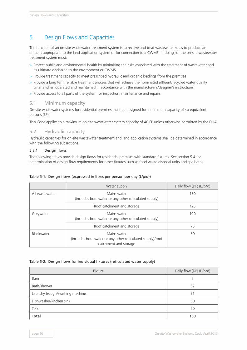
5.2.1 Design flows
The following tables provide design flows for residential premises with standard fixtures. See section 5.4 for determination of design flow requirements for other fixtures such as food waste disposal units and spa baths.
Table 5-1: Design flows (expressed in litres per person per day (L/p/d))
Water supply Daily flow (DF) (L /p/d)
All wastewater Mains water (includes bore water or any other reticulated supply)
150
Roof catchment and storage 125
Greywater Mains water (includes bore water or any other reticulated supply)
100
Roof catchment and storage 75
Blackwater Mains water (includes bore water or any other reticulated supply)/roof
catchment and storage
50
Table 5-2: Design flows for individual fixtures (reticulated water supply)
Fixture Daily flow (DF) (L /p/d)
Basin 7
Bath/shower 32
Laundry trough/washing machine 31
Dishwasher/kitchen sink 30
Toilet 50
Total 150
On-site Wastewater Systems Code April 2013
Design Flows and Capacities
page 16

5.2.2 Prohibited discharges
Unless otherwise approved by the relevant authority, no person shall permit or cause any of the following discharges into an on-site wastewater system:
> Any storm water, including roof and rainwater tank overflow, and surface drainage waters
> Any back flush waters from a swimming pool or water softener
> Any discharge or back flush from a spa bath/pool in excess of 680 litres capacity or in the case of a CWMS, unless otherwise accepted by the relevant authority
> Any sanitary napkin, clothing, plastic material or liner
> Any trade waste (see section 1.5)
> Any petrol or other flammable or explosive substance whether solid, liquid or gaseous
> Any other matter or substance which, in the opinion of the relevant authority, would impair the effective working
of an on-site wastewater system or CWMS.
5.2.3 Determination of primary treatment/septic tank capacity
Calculation of the minimum primary treatment/septic tank capacity requires determination of two factors:
1) Volume of daily flow into the tank; and 2) Volume for accumulation of sludge/scum.
The minimum primary treatment/septic tank capacity for a system collecting all wastewater from a residential premises is 3000 L (suitable for 6 EP). The minimum primary treatment/septic tank capacity for a system collecting only greywater or only blackwater is 1620 L (suitable for 6 EP). This is based on a four yearly desludging frequency. For a typical septic tank diagram, see appendix A figure A7.
For all primary treatment/septic tank capacities, including non-residential premises, the minimum effective tank capacity (in litres) is obtained by using Equation 1 as follows:
For daily flows and sludge/scum volumes for typical residential dwellings, see tables 5-1 and 5-3 respectively. For non-residential premises, for example restaurants, staff workplaces and schools, see appendix E.
Table 5-3: Sludge and scum accumulation rates for residential premises
Type of wastewater Sludge/scum rate (S) (L/p/y)
All wastewater 80
Greywater 40
The capacity of the primary treatment/septic tank must be of sufficient volume to accommodate the sludge/scum generated between desludging cycles. For residential premises, the desludging frequency is generally four years.
It is recognised that in commercial/industrial premises this may be impracticable, thus resulting in excessively large chambers. Subject to acceptance by the relevant authority, the desludging frequency may be reduced as per table 5-4.
See section 11.3.3 of this Code for sludge disposal requirements.
1 Or as otherwise specified by appendix E. This appendix provides a range of load factors (P1, S, P2 and DF) to assist in determining the capacity of the septic tank or primary treatment compartment. It may be necessary to add a number of individual uses to obtain the sludge /scum and daily flow total.
Minimum Effective Capacity (L) = (P1 x S x Y) + (P2 x DF) (Equation 1)
Where: P1 = Number of persons using the system (p) 1 S = Rate of sludge/scum accumulation in litres per person per year (L /p/y) 1 Y = Desludging frequency in years (y) P2 = Number of persons using the system (p) 1 DF = Daily flow in litres per person per day (L/p/d) 1
On-site Wastewater Systems Code April 2013 page 17
Design Flows and Capacities

Table 5-4: Desludging frequency for commercial/industrial premises
Annual sludge/scum accumulation (P1 x S) (L/y) Desludging frequency (Y) (y)
Less than 5000 4
Between 5000 and 10 000 2
Greater than 10 000 1
5.2.4 Connection to a CWMS – use of existing primary treatment/septic tanks
Where permitted by the relevant authority, use of existing primary treatment/septic tanks may be allowed. Refer to appendix F for further information.
5.3 Organic capacityDesign organic capacities (BOD5 loads) for on-site wastewater systems shall be determined by using equation 2 and table 5-5.
Table 5-5: BOD5 loadings
Source of wastewater BOD5 loading (g/p/d) 1
Raw sewage 70
After primary treatment/septic tank 50
Non-residential premises Refer to appendix E
Non-standard fixtures (i.e. spa baths, food waste disposal units) Refer to section 5.4 and tables 5-6 and 5-7
1 Or as otherwise specified by appendix E.
Design organic capacity (g/d) = P2 x BOD5 (Equation 2)
Where: P2 = Number of persons using the system (p) 1 BOD5 = Organic loading rate in grams per person per day (g/p/d) 1
Example 5-1
An AWTS (after primary treatment/septic tank) for a residential dwelling serving up to six persons would require an organic capacity as follows:
P2 = 6 p
BOD5 = 50 g/p/d
P2 x BOD5 = 6 p x 50 g/p/d = 300 g/d
Example 5-2
A restaurant (no liquor licence, four employees) catering for a maximum of 100 guests per day and having a suitable food waste disposal unit and septic tank installed would require an AWTS designed for an organic load as follows:
P2 = 100 p (guests) + 4 p (staff) = 104 p
BOD5 = 10 g/p/d (see Appendix E) + 5 g/p/d (50% increase for FWDU, see table 5-7) = 15 g/p/d
P2 x BOD5 = 104 p x 15 g/p/d = 1560 g/d
On-site Wastewater Systems Code April 2013
Design Flows and Capacities
page 18

5.4 Non-standard fixturesNon-standard fixtures are permitted, provided the increased hydraulic and organic capacity requirements of the whole on-site wastewater system are considered.
5.4.1 Spa baths and food waste disposal units
A spa bath is a fixture, having a capacity of up to 680 litres, which incorporates facilities for injecting air bubbles or jets of turbulent water and connects to the wastewater system in the same manner as a standard bath. Sizing of the on-site wastewater system and land application system is dependent on the capacity of each spa bath and may require an increase in the capacity of the on-site wastewater system in accordance with table 5-6. The increase in effective capacity must be calculated for each unit.
Food waste disposal units may be installed in kitchens of residential premises, provided that the effective capacity of the on-site wastewater system is increased in accordance with table 5-7 to allow for accumulation of additional solids. The increase in effective capacity must be calculated for each unit.
Table 5-6: Design criteria for spa baths
Spa bath capacityPrimary treatment/ septic tank sludge/ scum capacity (S)
Hydraulic capacity/ daily flow
BOD5 load
< 120 L No increase No increase No increase
121 L – 370 L No increase Increase by 250 L No increase
371 L – 680 L No increase Increase by 500 L No increase
Note: The land application area must be sized to accommodate the additional hydraulic load. Excessive use of the spa bath may overload the land application system and require additional capacity within the land application system to handle surges in hydraulic load.
Table 5-7: Design criteria for food waste disposal units
Type of premisesPrimary treatment/ septic tank sludge/ scum capacity (S)
Daily flow (DF) BOD5 load
Domestic residential Increase by 50% No increase Increase by 33%
Non-domestic residential Increase by 50% Increase by 10% Increase by 33%
Restaurants/dining meals No increase Increase by 10% Increase by 50%
5.4.2 Commercial kitchens
Unless otherwise directed, the discharge from any kitchen sink and/or dishwasher in a commercial kitchen shall connect to an approved pre-treatment apparatus.
The pre-treatment apparatus shall be installed in accordance with the relevant authorities’ requirements. See also trade waste requirements (section 1.5).
5.4.3 Commercial and other premises with on-site systems
For premises which require an on-site wastewater system but are not a standard residential premises, the design flows and organic loadings are provided in appendix E of this Code. These criteria must be used when designing such systems.
On-site Wastewater Systems Code April 2013 page 19
Design Flows and Capacities

6 Treatment SystemsIn most cases, wastewater must undergo some form of appropriate treatment prior to discharge to a land application system or CWMS. All products used to treat wastewater must be approved by the DHA prior to sale or use in South Australia (see chapter 12). Common types of treatment systems and their minimum requirements are described below.
6.1 Septic tanksSeptic tanks for use in South Australia must comply with the requirements of AS/NZS 1546.1 On-site domestic wastewater treatment units Part 1: Septic tanks. However, it should be noted that septic tank minimum effective capacities must be in accordance with chapter 5 and appendix E of this Code.
For product information on septic tank capacities greater than 5000 L, contact the DHA.
6.2 Aerated wastewater treatment systemsAerated wastewater treatment systems must comply with the requirements of AS/NZS 1546.3 On-Site domestic wastewater treatment units Part 3: Aerated wastewater treatment systems. However, the hydraulic and BOD5 loadings for these systems must comply with chapter 5 and appendix E of this Code.
For product information on systems greater than 10 EP, contact the DHA.
6.3 Aerobic sand filtersAerobic sand filter treatment systems shall be subject to specific design appropriate to their intended application. A DHA product approval must be obtained for each sand filter design, covering the design, installation and operation of the model. The relevant authority then approves installation of the systems in accordance with the DHA product approval and this Code.
6.4 Reed bedsReed bed treatment systems for on-site wastewater management shall be subsurface flow reed beds and must be designed in accordance with the requirements of this Code. A DHA product approval must be obtained for each reed bed system, covering the design, installation and operation of the model. The relevant authority then approves installation of these systems in accordance with the DHA product approval and this Code.
6.5 Composting toilets The design, testing, selection and sizing of composting toilets shall be in accordance with the requirements given in AS/NZS 1546.2 Waterless Composting Toilets.
The composted material must be disposed of in accordance with AS/NZS 1546.2 and have completed a 12 month composting period in the composting toilet system before disposal. The composted material must be buried if disposal is to be on-site.
The burial site for composted material must have the same setbacks as land application systems utilising setbacks in accordance with appendix B of this Code.
Excess liquid from a composting toilet shall be collected as blackwater or combined with greywater and disposed of in accordance with the DHA product approval requirements and the installation approval conditions issued by the relevant authority.
On-site Wastewater Systems Code April 2013
Treatment Systems
page 20
7 Ancillary Structures
7.1 Access and inspection openingsTanks (including all new septic tanks) are required to have access and inspection openings shafted to the surface level using a DHA approved access shaft, however in some cases tanks are required to be extended to surface level without reduction in diameter.
All covers shall be terminated a minimum of 50 mm (for septic tanks) or 100 mm (for AWTS) above the finished ground surface level. The surrounding surface must be graded away from the cover(s) to prevent ingress of surface water. Inspection openings are to be fitted with a threaded access cap, concrete block surround and cover.
For connections to a CWMS, the relevant authority may require an existing septic tank to be shafted to surface level for maintenance purposes such as desludging, testing and inspection, by notice or as a condition of approval.
All access and inspection shafts and their extensions must be approved by the DHA prior to sale or use in South Australia and shall be designed and tested in accordance with AS/NZS 1546.1 (see chapter 12 of this Code).
7.2 Pump sumps and pumpsIn some cases it is necessary to pump effluent or recycled water to the land application area. Pumping will also be necessary to connect to a pressure sewer/effluent system or where the depth of the connection of the CWMS does not permit the connection of the wastewater system by gravity drains. See appendix F for pump and pump chamber requirements.
7.3 Vacuum collection chambersFor requirements for vacuum collection chambers and internal components, see appendix F.
7.4 Distribution sumpsA distribution sump is a device which provides a means of evenly distributing effluent via gravity to a land application system. In order to alternate flows to multiple land application systems, other devices may be used, such as an effluent diverter valve.
Distribution sumps shall be installed in accordance with the setback distances detailed in appendix B.
Distribution sumps must be approved by the DHA prior to sale or use in South Australia (see chapter 12).
7.5 Holding tanksSee section 10.2.
On-site Wastewater Systems Code April 2013 page 21
Ancillary Structures

8 Land Application Systems
8.1 Introduction The design of the land application system requires careful planning to ensure all public and environmental health requirements are met. Site and soil characteristics must be considered when designing a land application system in order to determine the most appropriate location, type and size of a land application system.
There are two approaches that can be used for designing the land application system – the South Australian approach as outlined in this chapter and the approach of AS/NZS 1547 On-site domestic wastewater management (see chapter 9 of this Code).
Note: Using a combination of both approaches is not acceptable.
The applicant/owner is required to provide evidence demonstrating that the site is capable of incorporating a safe and sustainable on-site wastewater system.
8.2 Site and soil assessmentMany factors are associated with the determination of site suitability, and the following aspects need to be investigated in assessing the site.
8.2.1 Wastewater engineer’s report
The design of a land application system is dependent on the site and soil characteristics. A site intended for land application of effluent must be assessed by a wastewater engineer who must provide a report to the relevant authority confirming that the site and soil is suitable for long term effluent disposal or use of recycled water as per the requirements of this Code.
For indirect assessments, all soil samples shall be logged and described in accordance with AS 1726 Geotechnical Site Investigations or another recognised classification system based on the Unified Soil Classification (USC) system. Site characteristics must also be considered (see section 6.2.2). The report should provide a description of each soil layer encountered in each borehole and, in addition to classifying the soil, statements required by table 8-1.
Where the site fails to satisfy any of the site and soil assessment criteria, the wastewater system may need to be modified to include additional treatment and/or disposal requirements, or alternatively, require off-site effluent disposal. This may require further advice from a wastewater engineer.
On-site Wastewater Systems Code April 2013
Land Application Systems
page 22

Table 8-1: Site and soil report requirements
The wastewater engineer must provide a site and soil suitability report to the relevant authority. The report must include, but not be limited to:
> Details of the investigations carried out
> Site plan clearly showing:
> Soil sampling locations
> Allotment dimensions
> Location and dimensions of the proposed land application system
> Existing and proposed buildings and structures e.g. retaining walls
> Details of earthworks proposed as part of the site development
> Type of proposed system to be installed
> Information about the soil types encountered at the sampling locations in the area of the proposed land application system
> Nominated effluent percolation rate (EPR), design loading rate (DLR) or design irrigation rate (DIR) as applicable 1
> Design of the land application system including soil horizon at which the base of the land application system is to be founded
> Assessment of site suitability for long term effluent disposal/reuse
> A summary of site characteristics as described in section 8.2.2
> Supporting information with respect to climate characteristics including rainfall and evaporation which may affect the performance of the wastewater system
> Comments regarding features on adjoining allotments which may affect or be affected by the proposed wastewater system
> Any required surface water diversion
> Any limitations of the proposed system
> Any other requirements of the relevant authority.
1 Locations with highly permeable soils have an increased risk of effluent /recycled water polluting surface and/or ground waters. Careful consideration is necessary to mitigate the risk, and additional design and/or construction may be necessary. Soils demonstrating a percolation rate of greater than 150 mm /hour or category 1 and 2 soils as determined by AS/NZS 1547 (see chapter 9) require additional consideration. The site and soil assessment report shall include statements, supporting information and detailed strategies which will be used to minimise the risk of effluent/recycled water from the on-site wastewater system polluting ground and/or surface waters.
On-site Wastewater Systems Code April 2013 page 23
Land Application Systems

8.2.2 Site characteristics
The following site characteristics are required to be assessed as part of a site and soil report for the types of systems described in this chapter. See also chapter 9 for systems utilising the AS/NZS 1547 approach (see note 1).
a) Land slope
Land slope should not be greater than 20% (1 in 5) (see note 2).
b) Flooding
The site should not be subject to inundation or flooding more frequently than 1 in 10 years. Relevant authorities may impose other requirements relevant to their jurisdiction (see note 1).
c) Water table
The depth to a subsurface seasonal, tidal or permanent water table, fresh or saline, should be greater than 1.2 m from the ground surface level (see notes 2, 3 and 4). In the case of a subsurface disposal system, the base of the trench shall be at least 500 mm above the highest level of the water table.
d) Bedrock
The depth to bedrock or cap rock shall be suitable for the proposed system. For subsurface disposal systems, the depth of rock shall be at least 1.2 m below surface level provided the soils are suitable for application of effluent. The base of the subsurface disposal system must be at least 500 mm above any bedrock or cap rock (see notes 2 and 3).
e) Land area
The size of the area of land available for the land application system within the allotment must be adequate and suitable for the intended use.
f) Location of existing development
The location of existing development on the site or on adjoining sites, including upslope from the proposed land application area, must be considered to ensure that they do not adversely affect the proposed system or existing development. Care should also be taken to ensure compliance with the respective setback distances specified in this Code (see appendix B).
g) Land use
The number of persons using the site, the nature of the facilities to be installed and the type of land use will affect the capability of the design of the land application system (see chapter 5 and appendix E).
h) Availability of water
Some premises are dependent on stored rainwater and this will limit the potential volume of effluent for disposal or reuse (see section 5.2.1).
Notes:
1) The relevant authority reserves the right to impose further requirements or restrictions for the land application system.
2) The applicant must ensure compliance with any other relevant Act or regulation
3) The 1.2 m depth is based on the assumption that the soil within the horizon is adequate for the proposed land application system.
4) Where the effluent disposal system is likely to be in a horizon subject to tidal water inundation, it will be necessary to determine that its placement will not create adverse environmental impacts within the marine (coastal) waters intertidal zone.
On-site Wastewater Systems Code April 2013
Land Application Systems
page 24

8.3 Subsurface effluent disposal systemsSubsurface effluent disposal systems rely on the proper assessment of site and soil characteristics (see sections 8.2.1 and 8.2.2) as well as an effective management regime to achieve efficient and safe long term subsurface effluent absorption by soil. The system relies on an effective primary treatment stage usually carried by a septic tank (see chapter 6), followed by a site specific subsurface soakage trench or soakage bed to distribute the effluent evenly and allow sufficient area for absorption into the soil.
8.3.1 System sizing
To determine the minimum requirements for a subsurface effluent disposal system, it is necessary to calculate the required contact area in square metres. The effective contact area of a soakage trench includes the combined areas of the base, side walls and end walls of the system. This does not apply to systems designed in accordance with AS/NZS 1547 (see chapter 9).
The formation of the biomass on the soil contact surfaces within the soakage system is a limiting factor on the effluent percolation. The cumulative effect of the biomass is greater in cohesive soils such as clay, silts and fine sands, the exception being when the soil is the limiting factor, for example heavy clay or rock.
If indirect assessment is used then permeability class and corresponding EPR shall be determined from the soil characteristics and USC classification in accordance with table 8-2.
Soils in permeability class ’Practically impermeable‘ shall be assessed using alternative method(s) if it is proposed to utilise them for land application of effluent/recycled water. Methods as described in AS/NZS 1547 are appropriate.
To calculate the required contact area for a subsurface soakage system, for a domestic dwelling with six persons, use the formula below:
Formula for system sizing
P2 x DF = required contact area in m2 for the total daily inflow (Equation 3)
EPR
Where:
P2 = number of persons using the system (p)
DF = daily flow in litres per person per day (L/p/d)
EPR = effluent percolation rate (L /m2/d)
Soil type Group symbol Permeability class EPR (L/m2/d)
Fine grained soilsCLAY or SILT, sandy or gravelly CLAY or SILT
Pt, OH, CH, MH, OL, CL, CI, ML
Practically impermeable
(see below)
Coarse grained soilsFine or medium SANDS, or clayey SANDS Silty or Clayey SANDS
silty SC, SM, SP, SW, GC, GM
Poor soakage 10
Clean coarse SANDS Clean GRAVEL
SP, GP, GW Good soakage 15
Table 8-2: Classification of Soils
On-site Wastewater Systems Code April 2013 page 25
Land Application Systems

Example 8-1
A residential dwelling serving up to six persons and having a reticulated water supply and soil classified by the wastewater engineer as having an EPR of 10 L /m2/d would require a subsurface disposal system sized as follows:
P2 = 6 p
DF = 150 L /p/d
EPR = 10 L/m2/d
P2 x DF =
6 x 150 = 90 m2 contact area
EPR 10
Example 8-2
A warehouse/store with four employees working only one shift (no shower facilities provided), served by a reticulated water supply and having a soil classified by the wastewater engineer to have an EPR of 10 L/m2/d would require a subsurface disposal system sized as follows:
P2 = from appendix E – number of staff per shift x number of shifts = 4 p/shift x 1 shift = 4
DF = 30 L /p/d
EPR = 10 L /m2/d
P2 x DF = 4 p x 30 L/p/d = 12 m2 contact area
EPR 10 L/m2/d
On-site Wastewater Systems Code April 2013
Land Application Systems
page 26

8.3.2 Subsurface disposal system construction
Requirements
Depth of soil The depth of the suitable soil horizon for the installation should be in accordance with the requirements of section 8.2.2.
Position The subsurface effluent disposal system should be positioned within the natural ground, be sited along a level contour, and the trench floor must be level. The relevant authority may permit variations where adequate geotechnical evidence is provided by a wastewater engineer.
Sloping sites On sloping sites, the preferred position of the subsurface disposal system is down slope from the building unless otherwise specified by a wastewater engineer. See also section 8.2.2 for slope requirements.
Water table Seasonal, tidal and permanent water tables are required to meet the criteria laid down in section 8.2.2.
Flow to the land application system
Flow to the subsurface effluent disposal system may be achieved by a number of means including direct gravity feed, dosing siphons and effluent distribution valves.
Where discharge to the subsurface effluent disposal system sited in the appropriate soil horizon cannot be achieved by gravity flow, it will be necessary to pump the effluent to the subsurface disposal system.
Excavation During excavation for the subsurface effluent disposal system, care should be taken to avoid smearing the trench wall and floor surfaces. Where smearing occurs, the typical characteristics of the soil should be reinstated using hand tools.
Aggregate 40mm aggregate complying with AS 2758.1 shall be used within trench and bed subsurface disposal systems unless otherwise specified by the wastewater engineer.
Filter cloth Any durable, permeable textile material suitable for use with soil, aggregate or earth.
Vehicle loadings The subsurface effluent disposal system must not be subject to vehicle traffic loadings.
Diversion of natural waters
The subsurface effluent disposal system must be protected from roof, surface and migrating subsurface waters by diverting these waters to a point beyond the effluent disposal area. See section 8.3.5.
Multiple trenches/soakage beds
Where multiple trenches/soakage beds are used, it will be necessary to either install a distribution sump to discharge effluent evenly to each trench, or use an effluent diverter valve. Multiple trenches should be of equal length as far as is practicable. An induct vent is required to be provided on the inlet pipe to each run of a multiple soakage trench/soakage bed system.
Alternatively, the induct vent may be located between the septic tank outlet and the inlet to the distribution sump. In this case, each pipe entry into each multiple run of the soakage trench shall be fitted with a riser shafted to ground surface level as an inspection shaft and then finished with an approved threaded access cap and concrete block and cover.
Where the effluent is pumped to the subsurface effluent disposal system, venting requirements must be carried out in accordance with AS/NZS 3500.
Setback distances See appendix B for setback distances.
On-site Wastewater Systems Code April 2013 page 27
Land Application Systems

8.3.3 Soakage trenches
The common forms of soakage trench used for subsurface effluent disposal are the tunnel system and the perforated pipe system (see appendix A figures A8 and A9).
The soakage trench may be installed in single or multiple runs depending on the length, width and depth of the soakage trench, the length and/or width of the allotment and the direction of landfall. Appendix A figures A10, A11 and A12 show examples of different sizes to achieve the requirements for a standard six person system with a soil EPR of 10 L/m2/d.
Trench dimensions
Width:
> 1200 mm - 2500 mm using a single run of plastic tunnel or perforated pipe.
Depth:
> Using plastic tunnel: 400 mm
> Using perforated pipe: 300 mm - 600 mm, being the distance between the bottom of the pipe and trench base.
Note: Unless otherwise stated standard trench configuration is 1200 mm width by 400 mm depth for a tunnel trench and 1200 mm width by 300 mm depth for a perforated pipe trench.
8.3.4 Soakage bed
A soakage bed may be used as an alternative to a soakage trench. This type of soakage system is appropriate only where site gradients are minimal (less than 1%).
Appendix A figure A13 details a typical soakage bed layout.
The contact area of the soakage bed is the area of the base and all walls. The wall area is calculated using a wall height of 400 mm for the plastic tunnel system, or 300 mm to 600 mm for the perforated pipe system.
When positioning the plastic tunnel or perforated pipe within the soakage bed:
> The tunnel or perforated pipes shall be parallel to the longest dimension of the bed and the natural ground contour, and be level.
> Parallel runs of tunnel or perforated pipe shall not be more than 2000 mm apart.
> The distance from the edge of the bed to a run of tunnel or perforated pipe shall not be more than 1000 mm.
> The space surrounding the tunnels or to the top of the perforated pipes shall be filled with 40 mm aggregate or as otherwise specified by the wastewater engineer.
> The whole of the constructed bed area shall be covered with a filter cloth before backfilling with friable soil.
> A distribution sump or other distribution device (see section 7.4) shall be used to distribute the effluent to each run of tunnel or perforated pipe to provide even distribution.
Note: Where a subsurface disposal system is proposed to be constructed in a soil horizon greater than 2500 mm below the surface level, a permit should be obtained from the Water Licensing Branch, Department of Environment, Water and Natural Resources.
Example 8-3
Trench dimensions for a standard plastic tunnel system are 1.2 m width x 0.4 m depth.
The contact area for one linear metre is: (1.2 m + (0.4 m x 2)) x 1 m = 2 m2
Length of trench for a standard dimension system serving up to six persons and based on an EPR of 10 L /m2/d is:
Tunnel system
90 = 45 m
2
On-site Wastewater Systems Code April 2013
Land Application Systems
page 28

8.3.5 Diversion trench
Migrating surface and subsurface water can affect the capability of the system to dispose of the effluent.
Where the land fall and/or the geotechnical evidence indicates actual or potential ground water movement, a diversion trench may be required.
The diversion trench shall be installed so that surface and subsurface water is diverted away from the disposal area.
Where the site is flat, it is not practical to install a diversion trench.
On some sites, the diversion trench should be located upslope from the building and be of a depth that will arrest migrating subsurface water flow that may affect the subsurface effluent disposal system (see appendix A figures A11 and A12).
a) Diversion trench construction
The diversion trench shall comply with the following requirements:
> The base of the diversion trench should be deeper than the effluent disposal system base.
> The diversion trench shall be lined with 0.3 mm PVC or polyethylene placed on the trench bottom and the side nearest to the effluent disposal system and be extended to the ground surface level.
> A DN 100 or other approved perforated pipe with the perforations facing upward shall be placed on the top of the PVC or polyethylene sheeting located at the base of the trench.
> The trench shall be filled with 40 mm aggregate to the surface level.
> The soil shall be mounded between the diversion and the soakage trench (see appendix A figure A11).
> The outlet from the perforated pipe shall be extended to discharge at ground surface level at a point down slope from the subsurface soakage system.
> The diversion trench width shall be 300 mm minimum.
b) Roof waters
All roof waters shall be diverted away from the land application area. Where practical, roof waters should be diverted to the street water table or to a point beyond the disposal area so that it has no impact on the operation of the land application system (see appendix A figure A14).
8.4 Surface irrigation systemsThis section covers surface irrigation methods for recycled water application (refer to appendix A figure A14).
The land application area must be dedicated to the sole use of receiving recycled water. It must be landscaped, preferably with shrubs and trees, and should be designed to discourage pedestrian and vehicle access.
8.4.1 Recycled water quality requirements
Recycled water used for land application must be treated to a minimum secondary standard. The quality of effluent must comply with the following requirements:
> A mean value of BOD5 less than 20 mg/L
> A mean value of total suspended solids (SS) less than 30 mg/L
> A median value of thermotolerant coliforms (E. coli) less than 10 org./100 mL
> Where chlorination is the disinfection process, the apparatus shall be designed to reliably ensure the FAC shall be between 0.5 mg/L and 2.0 mg/L at the maximum effluent flow rate of 10 L/min.
For chlorine requirements for non-domestic premises, contact the DHA.
8.4.2 Sizing of the irrigation area
The land application area for surface irrigation must be designed by a wastewater engineer and be sized to accommodate the total flow from the premises using an appropriate design irrigation rate (DIR).
Historically, a DIR of 4.5 L/m2/d has been found to be suitable for surface irrigation throughout South Australia. However, the wastewater engineer must take into consideration all requirements of this Code when determining the design irrigation rate.
On-site Wastewater Systems Code April 2013 page 29
Land Application Systems

All additional plumbing fixtures, for example food waste disposal unit and spa bath, will require an increase in the treatment and reuse capacities (see section 5.4).
To determine the total load for sizing of the irrigation area, it may be necessary to add a range of use conditions, including loadings, where applicable.
If the land gradient is greater than 20% (1:5) the wastewater engineer shall require drip or subsurface irrigation or employ other means to prevent runoff from the site.
8.4.3 Irrigation area requirements
Requirements
Soil cultivation The land application area must incorporate at least 150 mm depth of friable soil and/or other suitable material such as pine bark, woodchips, scoria etc. over its entire surface.
Plants The area should be planted with appropriate flora to ensure transpiration of the recycled water. Plants must be suitable for transpiration of recycled water and be salt and nutrient tolerant (see appendix D). If existing vegetation is not suitable or adequate for evapo-transpiration, extra trees and shrubs must be planted, and additional landscaping may be necessary.
Vegetables and food plants
As a public health precaution, spray irrigation is not to be used on vegetables or food plants.
However, if drip irrigation is used, fruit and nut trees may be allowed, provided the produce has no contact with recycled water.
Pedestrian traffic Pedestrian traffic should be excluded from the land application area. This does not include access for maintenance purposes.
Roof waters All roof waters must be diverted away from the land application area.
Flooding The land application area should not be located on land prone to waterlogging or subject to flood or surface water inundation (see section 8.2).
Run off Landscaping must be designed so that the recycled water does not pool within, or run off from, the land application area. Where the disposal area is constructed over rock, or where there is a danger of recycled water escaping to adjacent areas for example on steep sites, the design engineer must specify the measures to be taken to ensure that recycled water is totally contained within the dedicated area.
Signage Warning signs must be positioned within the land application area to indicate that recycled water is being used for irrigation. The signs must be on a white background with red lettering of at least 20 mm in height. The signs must be clearly visible from all sides and must contain a warning such as: RECYCLED WATER – AVOID CONTACT/CONSUMPTION
Prevention of contamination
Any spray irrigation system must be installed, operated and maintained to prevent contamination of rain water catchment areas and rain water tanks.
Example 8-4
The irrigation area for a residential dwelling for up to six persons is designed by a wastewater engineer using a nominated irrigation rate of 4.5 L /m2/d.
For a daily flow of 150 L per person and a minimum of six persons, the area of the surface irrigation system is:
6 x 150 = 200 m2
4.5
On-site Wastewater Systems Code April 2013
Land Application Systems
page 30
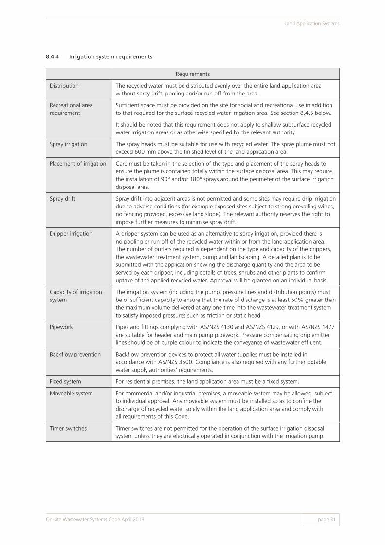
8.4.4 Irrigation system requirements
Requirements
Distribution The recycled water must be distributed evenly over the entire land application area without spray drift, pooling and/or run off from the area.
Recreational area requirement
Sufficient space must be provided on the site for social and recreational use in addition to that required for the surface recycled water irrigation area. See section 8.4.5 below.
It should be noted that this requirement does not apply to shallow subsurface recycled water irrigation areas or as otherwise specified by the relevant authority.
Spray irrigation The spray heads must be suitable for use with recycled water. The spray plume must not exceed 600 mm above the finished level of the land application area.
Placement of irrigation Care must be taken in the selection of the type and placement of the spray heads to ensure the plume is contained totally within the surface disposal area. This may require the installation of 90º and/or 180º sprays around the perimeter of the surface irrigation disposal area.
Spray drift Spray drift into adjacent areas is not permitted and some sites may require drip irrigation due to adverse conditions (for example exposed sites subject to strong prevailing winds, no fencing provided, excessive land slope). The relevant authority reserves the right to impose further measures to minimise spray drift.
Dripper irrigation A dripper system can be used as an alternative to spray irrigation, provided there is no pooling or run off of the recycled water within or from the land application area. The number of outlets required is dependent on the type and capacity of the drippers, the wastewater treatment system, pump and landscaping. A detailed plan is to be submitted with the application showing the discharge quantity and the area to be served by each dripper, including details of trees, shrubs and other plants to confirm uptake of the applied recycled water. Approval will be granted on an individual basis.
Capacity of irrigation system
The irrigation system (including the pump, pressure lines and distribution points) must be of sufficient capacity to ensure that the rate of discharge is at least 50% greater than the maximum volume delivered at any one time into the wastewater treatment system to satisfy imposed pressures such as friction or static head.
Pipework Pipes and fittings complying with AS/NZS 4130 and AS/NZS 4129, or with AS/NZS 1477 are suitable for header and main pump pipework. Pressure compensating drip emitter lines should be of purple colour to indicate the conveyance of wastewater effluent.
Backflow prevention Backflow prevention devices to protect all water supplies must be installed in accordance with AS/NZS 3500. Compliance is also required with any further potable water supply authorities’ requirements.
Fixed system For residential premises, the land application area must be a fixed system.
Moveable system For commercial and/or industrial premises, a moveable system may be allowed, subject to individual approval. Any moveable system must be installed so as to confine the discharge of recycled water solely within the land application area and comply with all requirements of this Code.
Timer switches Timer switches are not permitted for the operation of the surface irrigation disposal system unless they are electrically operated in conjunction with the irrigation pump.
On-site Wastewater Systems Code April 2013 page 31
Land Application Systems
8.4.5 Recreational area requirements
For single residential premises, the area provided for domestic, social and recreational use must be at least 50% of the surface irrigation area.
For multiple occupancy residential premises, this must be at least 25% of the area required for surface irrigation.
The relevant authority reserves the right to exempt commercial premises form this requirement. This requirement excludes land used for:
> Building and perimeter paving
> Pedestrian and vehicle access
> Vehicle parking, carports, garages and sheds
> Septic tank and wastewater treatment unit
> Surface recycled water irrigation area including setback distances of 1.5 m or less.
8.5 Shallow subsurface irrigationRefer to chapter 9 of this Code and AS/NZS 1547.
On-site Wastewater Systems Code April 2013
Land Application Systems
page 32

9 Use of AS/NZS 1547 On-site domestic wastewater management in South Australia
9.1 Australian / New Zealand Standard 1547 (AS/NZS 1547)There are two approaches that can be used for designing the land application system – the South Australian approach (see chapter 8 of this Code) or the approach in this chapter.
This chapter of the Code sets out the requirements of using AS/NZS 1547 for the design, construction and installation of land application systems.
Compliance is required with the South Australian amendments to AS/NZS 1547 as outlined in section 9.2 below. Where this Code is silent on an issue, reference should be made to AS/NZS 1547.
Note: Using a combination of the approach in chapter 8 of this Code and AS/NZS 1547 is not acceptable.
The relevant authority reserves the right to require design certification of a land application system by a wastewater engineer where necessary.
9.2 State amendments9.2.1 Hydraulic loadings and products
The land application system must be designed using products acceptable to DHA and based on the hydraulic loadings outlined in chapter 5 and appendix E of this Code.
9.2.2 Setback distances
The design of a land application system shall meet all required setbacks as detailed in appendix B of this Code.
9.2.3 Construction and installation
The construction and installation of land application systems shall also be in accordance with the relevant sections of this Code and any other requirements as specified by the relevant authority.
9.2.4 Other
The DHA may determine other amendments as deemed necessary.
9.3 Deemed to satisfyCompliance with the acceptable solutions in AS/NZS 1547 subject to the requirements in this section and the satisfaction of the relevant authority shall be deemed to satisfy the requirements of the Code.
On-site Wastewater Systems Code April 2013 page 33
Use of AS/NZS 1547
Requirements
Approval The holding tank must have a DHA product approval.
Capacity The holding tank shall have an effective capacity equal to at least 4 days design flow.
Location The holding tank shall be located so as to permit ease of access for the pump out vehicle.
Setbacks Setback distances for holding tanks are the same as for septic tanks (refer to appendix B).
Flood zones The holding tank should be located above the 1 in 10 year return flood event level.
Access and inspection openings
Access and inspection openings shall be in accordance with the product approval. See also chapter 5.
Alarm An audible and visual alarm with muting facilities for the audible component shall be provided and be located in a conspicuous position in either the laundry or kitchen to warn that the holding tank requires pumping out within 24 hours.
Owner/occupier responsibilities
The owner/occupier of the premises is required to:
1. Provide documentation to the relevant authority that the contents of the holding tank is being collected by an EPA licensed contractor and disposed of at a site approved by the relevant authority for the disposal of holding tank wastewater; and
2. Ensure the EPA licensed contractor provides copies of tracking sheets of such removals and disposal to the relevant authority and such other authorities as required by the approval. See section 11.3.4 for more holding tank wastewater disposal requirements.
10.2.3 Design, Installation and Performance requirements
10 Off-site Disposal
10.1 Community wastewater management systems (CWMS)In many South Australian towns, councils or the local authority have installed a CWMS for the collection and off-site treatment of sewage or septic tank effluent. Where this type of scheme is available, application must be made to the relevant authority for approval to connect. See chapter 3 and appendix F for connection requirements.
10.2 Holding tanks10.2.1 New land divisions
No holding tanks will be permitted in new land divisions.
This requirement should be considered at the early development stages of a Development Plan Amendment and/or land division proposal.
10.2.2 Existing allotments
Holding tanks may be permitted for existing allotments which have site characteristics unsuitable for the installation of an on-site land application system, subject to the relevant authorities’ requirements and the following considerations:
> Relevant Development Plans or any other policies which may be applicable to the site
> The opportunity for future servicing by CWMS, taking into account associated timeframes
> Options for pumping to a land application system located on another site. In this case, there must be a permanent legally binding agreement between both parties and this arrangement must be acceptable to the relevant authority.
Holding tanks are not permitted for existing allotments in Water Protection Areas as proclaimed under Section 61A of the Environment Protection Act 1993 without written approval from the DHA and the Environment Protection Authority (EPA). Compliance with other agencies’ legislation may also be required.
The relevant authority reserves the right to impose a condition requiring the owner of a site where a holding tank is located to use an alternative method of wastewater management if it becomes available.
On-site Wastewater Systems Code April 2013page 34
Off-site Disposal

11 Operation and Maintenance
11.1 General All on-site wastewater systems require ongoing operation and maintenance to ensure that the design performance of the system is achieved for its expected life. If not operated and maintained correctly, on-site wastewater systems will fail to comply with approved performance criteria which increases the risk to public and environmental health.
11.2 Operation and maintenance manualsThe designer, manufacturer and/or installer must prepare operation and maintenance manuals for all aspects of the on-site wastewater system. The designer, manufacturer and/or installer must ensure that operation and maintenance manuals are provided to all operators of an on-site wastewater system at the time of installation or on occupation of the premises.
Further information is provided in chapter 12.
For assistance in preparing operation and maintenance guidelines, refer to AS/NZS 1547. The relevant authority may request copies of the documents.
11.3 Maintenance and servicing11.3.1 Owners/operators
Owners/operators of on-site wastewater systems shall ensure that they hold maintenance and service contracts for their on-site wastewater systems, where applicable under the conditions of approval. Owners/operators shall ensure that all maintenance and servicing is undertaken by an appropriately trained person with experience in servicing wastewater systems (see section 11.4).
Owners/operators must ensure that:
> Operation and maintenance procedures are undertaken to a regular schedule appropriate to the nature and type of the on-site wastewater treatment and land application system, and in accordance with any manufacturers’ or designers’ instructions and/or the conditions of approval from the relevant authority.
> Continuity of operation and maintenance is achieved throughout changes of ownership, occupier and/or use or any development of the premises.
11.3.2 Relevant authority
The local council may choose to undertake septic tank desludging (particularly in areas with a CWMS) and/or provide maintenance services through a contractor or other agents (see appendix F).
The relevant authority reserves the right to request that owners and/or service agents provide copies of maintenance/servicing contracts and reports.
11.3.3 Primary treatment tank/septic tank sludge disposal
Primary treatment tank/septic tank desludging must be carried out by an EPA licensed contractor, and sludge shall be disposed of in accordance with the South Australian Biosolids Guidelines. See chapter 11.6 of this Code for further information.
Note: This clause applies only to the contents of primary treatment tanks and septic tanks and does not apply to holding tank wastewater.
11.3.4 Holding tank wastewater disposal
Holding tank wastewater must be disposed of by an EPA licensed contractor at a wastewater treatment plant or wastewater treatment lagoon, as approved by the relevant authority and in accordance with that relevant authority’s requirements.
On-site Wastewater Systems Code April 2013 page 35
Operation and Maintenance

11.4 Service providersAWTS servicing must be undertaken by an appropriately trained person. This person must have completed a training course as specified by the DHA. Additionally, manufacturers may require these service providers to undertake further training specific to their particular units. In the first instance, service providers should contact the manufacturers to confirm individual system servicing requirements.
Servicing must be undertaken in accordance with the manufacturer’s instructions and the conditions of the relevant authority’s approval.
Service providers must forward a copy of each service record to the relevant authority and notify that authority if they cease to service the system.
11.4.1 Availability of service
Emergency service should be provided within 24 hours of a service request at all times.
11.5 Inspection and monitoring programsThe relevant authority reserves the right to undertake regular performance monitoring of installed on-site wastewater systems to determine the ongoing performance. This may include sampling and testing of effluent or recycled water quality, land application system assessment and/or other sampling, testing or monitoring as determined by the relevant authority.
The objectives of an inspection and monitoring program may include:
> To protect the health of the residents of the premises, neighbours and general community
> To identify and trouble-shoot problems in the early stages before they become serious and expensive to correct
> To ensure necessary maintenance, repair or component replacement is undertaken
> To maintain an accurate record of the compliance with performance criteria, condition and types of on-site wastewater systems and associated land application systems within the relevant authority’s area
> To protect water resources and other local drinking water sources, including wells, from contamination
> To protect the ecosystems of rivers, lakes and coastal waters and prevent adverse conditions and the need for costly rehabilitation efforts
> To undertake the program in a manner that is fair and reasonable to the community as a whole.
11.6 Septic tank desludgingWhen correctly sized and maintained, the septic tank provides adequate capacity for the retention of the sludge and scum, and ensures a 24 hour retention of the hydraulic load to enable settlement. Where the retention period is less than 24 hours, the amount of solids in suspension increases and results in the discharge of excessive amounts of solids to the effluent disposal systems. This additional organic load can contribute to system failure.
Septic tanks specified for single and multiple residential dwellings are typically sized based on a four yearly desludging frequency.
Septic tanks for non-residential premises may be designed to allow a period between one and four years before desludging and thereafter they need to be desludged in accordance with the approval conditions. Refer to section 5.2.3 for further information.
An effective maintenance program should include annual checking to ensure a free capacity equal to one third of the effective liquid depth within the detention zone as measured in the first compartment. If the accumulation of sludge and scum has decreased the capacity below this level, then the tank requires desludging.
For information on the disposal of septic tank sludge, contact the Environmental Health Officer at the local council office for the area, or the DHA for unincorporated areas.
Note: All access openings must be maintained so as to be gas and water tight.
11.7 Maintenance of on-site wastewater systems connected to a CWMSSee section F8 of appendix F for maintenance of systems connected to a CWMS.
On-site Wastewater Systems Code April 2013
Operation and Maintenance
page 36
12 Product Approvals
12.1 On-site wastewater systems covered by Australian StandardsThis section of the Code sets out the minimum requirements for product approval of an on-site wastewater system covered by an Australian/New Zealand Standard.
Unless stated otherwise in this Code, the function, context of use and performance requirements given in the relevant Australian Standard must apply to an on-site wastewater treatment system (or component thereof).
This section applies to on-site wastewater systems up to a capacity of 10 EP. Requirements for systems above 10 EP will be determined by the DHA on a case by case basis.
12.1.1 Legislation
Pursuant to the Wastewater Regulations, a person must not sell a system for use as an on-site wastewater system unless the system is the subject of a product approval. The DHA is the relevant authority for issuing product approvals.
12.1.2 Application procedure
The manufacturer should make preliminary contact with the DHA to discuss application requirements.
To obtain a product approval, an application must be made to the DHA. Supporting information must be provided in accordance with chapter 12.1.4.
Product approvals will be subject to conditions and be granted for a period of five years (or a period as determined by the DHA) after which time it will become void unless the approval is renewed prior to the expiry date.
Product approval renewal
The manufacturer must submit an application to the DHA for renewal of the approval. Assessment for renewal of a product approval shall take into account all application documentation requirements and, where applicable, the performance monitoring results undertaken by the manufacturer.
Any modification or variations of the approved design will require a formal application to the DHA for separate consideration and variation of approval, which may require further documentation and/or product testing.
12.1.3 Product certification
The manufacturer must obtain certification to the relevant part of AS/NZS 1546 or other Standard(s) deemed relevant by the DHA, for each model of an on-site wastewater treatment system (or component thereof).
The manufacturer shall arrange for the product certification program to be undertaken through an independent product certification agency which must be accredited by JAS-ANZ.
On-site Wastewater Systems Code April 2013 page 37
Product Approvals
12.1.4 Application requirements
An application for product approval must be submitted in the format determined by the DHA. The application must contain:
> The prescribed fee
> Copies of certification documentation from an independent product certification agency accredited by JAS/ANZ, confirming certification of the on-site wastewater treatment system to the relevant part of AS/NZS 1546 (or other relevant standards)
> A certification evaluation report prepared by the product certification body detailing the testing methods used, inclusion of all data, comparing performance components with test criteria and security arrangements to ensure testing integrity
> Documentation that the laboratories used for off-site chemical and bacteriological determinations are National Association of Testing Authorities (NATA) registered to carry out analyses for the parameters specified
> A statement of the warranty and guaranteed service life of the prefabricated on-site wastewater treatment system including all its components
> A complete and detailed specification of the product describing the basis for design, materials, methods of construction, effluent quality, servicing intervals and manner of operation of all equipment supplied
> Detailed engineering drawings of the system, drawn to scale, clearly showing all components
> Copies of the installation, operation and maintenance manuals for the system.
Note: Product literature supplied with the application may need to be changed to reflect product approval conditions or other changes as required by the DHA.
a) Operation and maintenance manual
Each on-site wastewater system must be accompanied by an operation and maintenance manual prepared by the manufacturer. The manufacturer must provide the manual to the owner at the time of system installation or on occupation of the premises. The manual must be written so as to be easily understood by the intended reader and must include, at a minimum:
> The product’s name and model number
> The wastewater volume and, where applicable, organic load able to be treated
> A clear statement of the types of wastewater/waste that can be effectively treated by the product
> A list of household substances that, if discharged to the product, may adversely affect the integrity of the product, the process, or the environment
> Comprehensive operation and maintenance instructions that clearly delineate proper function of the product, operating and maintenance responsibilities of the owner and authorised service personnel, as well as those of the manufacturer
> The required effluent quality to be produced by the system and its allowable end-uses
> Requirements for the periodic removal of sludge from the system
> A course of action to be taken if the product is to be used intermittently or if extended periods of non-use are anticipated
> Detailed methods and criteria to be used to identify product malfunction or problems
> The name and telephone number of an appropriate service representative to be contacted in the event that a problem with the product occurs
> Any additional requirements specified by the relevant authority.
On-site Wastewater Systems Code April 2013
Product Approvals
page 38

b) Installation manual
Manufacturers must provide comprehensive and detailed installation instructions to authorised representatives. The manual must be written in a clear and concise manner and must include (if applicable), as a minimum:
> A numbered list of product components and an accompanying illustration, photograph or schematic in which all components are respectively identified
> Design, construction and material specifications for the components of the product
> Plumbing component schematics
> Electrical wiring schematics
> Offloading, unpacking and installation instructions including safety considerations, identification of fragile components and measures to be taken to avoid damage to the product
> A process overview of the function of each component and the expected function of the product when all components are properly assembled, connected and operating
> A clear definition of product installation requirements including plumbing and electrical requirements, ventilation, air intake protection, bedding, hydrostatic displacement protection, water tightness, miscellaneous fittings and appurtenances
> Any additional requirements specified by the relevant authority.
12.2 Systems not covered by an Australian/New Zealand StandardThis section of the Code sets out the minimum requirements for product approval by the DHA of an on-site wastewater system which is not covered by an AS/NZS Standard for on-site wastewater systems as dealt with in section 12.1.
This Code should not be interpreted to prevent the use of materials or products not specifically referred herein. If it is desired to use alternative and/or new materials and products not covered by this Code, they shall be submitted to the DHA for assessment.
12.2.1 Legislation
Refer to chapter 3 of this Code.
12.2.2 Product approval procedure
Refer to section 12.1.2.
12.2.3 Product certification
The manufacturer must contact the DHA to discuss product certification requirements. This may include certification to the relevant interstate/international guideline, for each model of the product.
The manufacturer shall arrange for the product certification program to be undertaken through an independent product certification agency which must be accredited by JAS-ANZ or other equivalent organisation(s) as agreed by the DHA.
The DHA reserves the right to request for endorsement of the certification by a wastewater engineer.
On-site Wastewater Systems Code April 2013 page 39
Product Approvals

12.2.4 Application criteria
An application for product approval must be submitted in the format determined by the DHA. The application for product approval must contain:
> The prescribed fee
> Copies of certification documentation from a certification agency accredited by JAS-ANZ or other equivalent organisation(s) as agreed by DHA, confirming certification of the on-site wastewater treatment system to be in compliance with the relevant standard/guideline
> A certification evaluation report prepared by the product certification body detailing the testing methods used, inclusion of all data sheets, comparing performance against the test criteria and detailing the security arrangements adopted to ensure testing integrity
> Documentation that the laboratories used for off-site chemical and bacteriological determinations are National Association of Testing Authorities (NATA) registered (or equivalent) to carry out analyses for the parameters specified
> A statement of the warranty and guaranteed service life of the prefabricated on-site wastewater treatment system including all its components
> A complete and detailed specification of the product describing the basis for design, materials, methods of construction, effluent quality, servicing intervals and manner of operation of all equipment supplied. This must be accompanied by supporting documentation
> Detailed engineering drawings of the system, drawn to scale, clearly showing all components
> Copies of the installation, operation and maintenance manuals for the system.
Note: Product literature supplied with the application may need to be changed to reflect product approval conditions or other changes as required by the DHA.
a) Operation and maintenance manual
Refer to section 12.1.4
b) Installation manual
Refer to section 12.1.4
12.2.5 Existing interstate or overseas approvals
Copies of interstate and overseas approvals, together with supporting information, may be submitted to support an application for a product approval. The DHA reserves the right to accept or reject this information or to have the applicant undertake further tests and/or independent investigations.
12.2.6 Recycled water compliance criteria
Recycled water compliance criteria will be determined by DHA on a case by case basis.
12.2.7 Design requirements
a) Design parameters
Refer to chapter 5 of this Code.
Note: The DHA reserves the right to vary, delete or request additional criteria as required.
On-site Wastewater Systems Code April 2013
Product Approvals
page 40

b) Design considerations
The product shall be designed to:
> Provide sufficient capacity for the design wastewater flow
> Prevent cross contamination between internal chambers
> Ensure even distribution of liquid over any filter bed or other medium that may form part of the treatment process
> Ensure that the entire structure and its associated components, for example inspection covers, access extensions, etc. are stable and suitable for their intended loads and operating/installation environment
> Provide appropriately sized access openings and inspection points for maintenance, desludging and clearing of blockages
> Ensure all access points are child proof and prevent access by unauthorised people
> Provide, where required, a suitable disinfection system
> Prevent foul air and gas build up within the system or the building(s)
> Prevent damage from superimposed loads or normal ground movement
> Perform to specified performance standards for the specified serviceable life
> Ensure the pump chamber permits ease of access for maintenance and the replacement of the pump
> Provide insulation against noise (the DHA reserves the right to require noise level testing to be undertaken)
> Ensure all tanks that comprise all or part of the product shall be designed in accordance with AS/NZS 1546.1 or as required by the DHA
> Ensure all the mechanical equipment is suitable for its intended load and operating environment
> Ensure all the electrical equipment complies with the relevant standard/guideline and/or with the regulatory authorities’ requirements
> Provide, where required, a suitable alarm system with audible and visible alarms with muting facility. The muting facility must reset to audible position after 24 hours of its use
> Provide marking in accordance with AS/NZS 1546.
Note: The DHA reserves the right to vary, delete or request additional criteria as required.
12.3 Permanent greywater systemsProduct approvals are required for the sale of all permanent greywater systems including greywater diversion and treatment systems.
Greywater diversion systems must be designed in accordance with the relevant Australian Standard/Australian Technical Specification and any other DHA requirements.
Greywater treatment systems must be designed in accordance with the relevant Australian Standards and any other DHA requirements.
Wastewater works approvals for the installation of a permanent greywater system are also required in accordance with this Code and any further information issued by the DHA.
Capacity requirements for permanent greywater systems are outlined in chapter 5 of this Code.
Where systems are to be installed in areas administered by water industry entities, the necessary approvals from the relevant authorities will be required.
Note: For information regarding temporary greywater systems, see appendix C.
On-site Wastewater Systems Code April 2013 page 41
Product Approvals

15.0m
2.5m
8.0m
45.0m
2.5m
2.5m
2.5m
3.0m
14.2m
2.5m
26.0m
15.5m
15.0m
14.5m
14.0m
13.5m
13.0m
12.5m
12.0m
11.5m
16.0m
induct vent
induct vent
induct vent
DN 100
DN 100
DN 100
3 x 15 metre plastic tunnel trenches(1200mm x 400mm)
SHED
BUILDING driveway
roof waterdischarge
landfall
Lot no. 256
BRISCOE ST
stormwater drainage easement
3000 litreprecast
septic tankaccess cover shaftedto surface level
DN 100inspection
shaftDN 100inspection shaft
DN 100 inspection opening
DN 100inspection shaft
upstream vent
overflow reliefgully
Example only. Not to scale.
Figure A1: Typical site layout plan
DN 100 inspection shaft
distributiondevice
inspection shaft(to surface level)inspection openingoverflow relief gullyupstream ventstormwater drain
paving
DN 100sewer drain
grade as perAS/NZS 3500
Appendix AFigure A1: Typical site layout plan
On-site Wastewater Systems Code April 2013
Appendix A
page 42

bedroom
lounge
family room
bedroom
bedroom
family room dining room
kitchen
bathroom
ensuite
laundry
Figure A2: Typical building layout plan
paving
DN 100 overflowrelief gully with
tap over
DN 65
DN 100 sewer drain
DN 65
DN 100inspection shaft
DN 50 double bowlconnector & trap
sink
DN 40untrapped wastes
DN 80 grate and DN 50 trapped waste
DN 65 floor waste gully withDN 80 riser
DN 80 floorwaste gullywith DN 80
riser
bath
w/m
WC pan shower
DN 40trapped waste
basin
trough
DN 100
DN 65
DN 100inspection
shaft
sewer draingrade as perAS/NZS 3500
DN 65 floor waste gullywith DN 80 riser
WCpan
basin
DN 40 trapped waste
shower
DN 65DN 100
DN 50upstream
vent
DN 100inspection shaft
DN 80 x 50tapered grate &
DN 50 untrappedwaste
DN 40untrapped
waste
Note: All plumbing must be inaccordance with AS/NZS 3500 Example only. Not to scale.
Figure A2: Typical building layout plan
On-site Wastewater Systems Code April 2013 page 43
Appendix A

Figure A3: Typical site layout plan – two tank system and split irrigation area
inspection shaftupstream vent
inspection shaftoverflow
relief gully
15m
14.2m
26m
45m
shed
driveway2.0m
DN 100inspection
point
inspection shaft(to surface level)
inspection opening
overflow relief gully
upstream vent
irrigation pipeline
stormwater drain
90 sprayhead
180 sprayhead
360 sprayhead
warning sign
o
o
o
8.0m
paving
warningsign
irrigationpipeline
accessopening
and cover(cover at
surfacelevel)
3000 litreseptic tank
AWTS
induct vent
DN 100inspection opening
access covershafted to
surface level
DN 100inspection
shaft
roof waters tostreet water
table
3.0m
Lot 19 Parker Avenue
0.5m1.5m
1.5m
warning sign
dedicated surface irrigation disposal area(5.0m x 15.5m)
(1) Dedicated surface irrigation disposal area (5.5m x 24.0m)
(2) Surface cultivated then covered with a100mm layer of friable soil plus 50mm of wood chips(3) Planted with salt & high nutrient tolerant shrubs
1.5m
shed onadjoiningboundary
16m
0.5m
Figure A3: Typical site layout plan - two tank system split irrigation area
social/recreationalarea
2.5m
0.5m
DN 100sewer drain
grade as perAS/NZS 3500
Example only. Not to scale.
BUILDING
On-site Wastewater Systems Code April 2013
Appendix A
page 44

shed
building
carport
roof waters to street water table
trench in accordance with manufacturer's/soil engineer's specifications
rising main to irrigation trench
street
overflow to existing sewer
14.1m
2.5m
Model X greywaterdiversion device
Figure A4: Typical greywater subsurface trench system
2.5m
3.0m
existingplumbing
Example only. Not to scale.
Figure A4: Typical greywater subsurface trench system
On-site Wastewater Systems Code April 2013 page 45
Appendix A
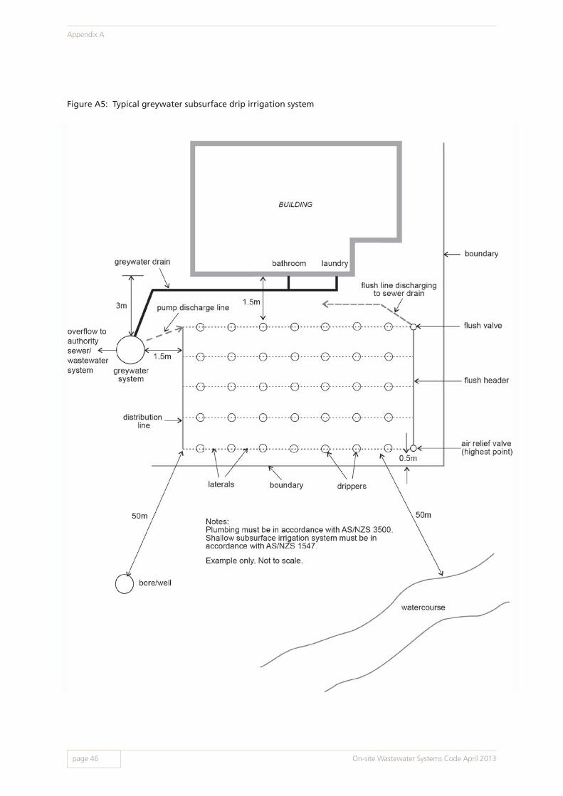
Figure A5: Typical greywater subsurface drip irrigation system
On-site Wastewater Systems Code April 2013
Appendix A
page 46

Figure A6: Typical building layout plan for sewage and greywater on-site wastewater treatment systems
On-site Wastewater Systems Code April 2013 page 47
Appendix A

Figure A7: Typical horizontal septic tank design
On-site Wastewater Systems Code April 2013
Appendix A
page 48

Figure A8: Soakage trench - typical tunnel system
On-site Wastewater Systems Code April 2013 page 49
Appendix A

Figure A9: Soakage trench - typical perforated pipe system
On-site Wastewater Systems Code April 2013
Appendix A
page 50

Figure A10: Typical distribution sump/ trench layout
On-site Wastewater Systems Code April 2013 page 51
Appendix A
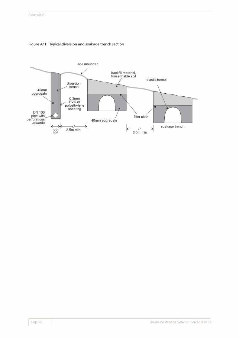
Figure A11: Typical diversion and soakage trench section
On-site Wastewater Systems Code April 2013
Appendix A
page 52

soakage trench (45 m x 1.2 m)
land fall diversion trench
septictank
building
induct vent
Figure A12: Typical layout utilising a diversion trench
On-site Wastewater Systems Code April 2013 page 53
Appendix A

inductvents
7.5m
10.25m
distributionto surface level
deviceDN 100
1.0m
1.0mmax.
2.0mmax.
2.0mmax.
1.0mmax.
0.5m
0.5m
0.5m
loose friable soil plastic tunnel ground surface
40mm aggregate
level basefilter cloth
varies
400mm
Figure A13: Typical soakage bedFigure A13: Typical soakage bed
On-site Wastewater Systems Code April 2013
Appendix A
page 54
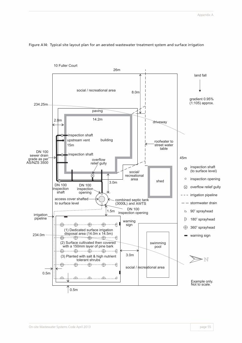
Figure A14: Typical site layout plan for an aerated wastewater treatment system and surface irrigation
234.25m
234.0m
DN 100sewer drain
grade as perAS/NZS 3500
Example only.Not to scale.
inspection shaftupstream vent
inspection shaftoverflow
relief gully
building15m
14.2m
26m
45m
shed
driveway2.0m
DN 100inspection
shaft
inspection shaft(to surface level)
inspection opening
overflow relief gully
irrigation pipeline
stormwater drain
90 sprayhead
180 sprayhead
360 sprayhead
warning sign
o
o
o
8.0m
paving
warningsign
irrigationpipeline
combined septic tank(3000L) and AWTS
DN 100inspectionopening
access cover shafted to surface level
DN 100inspection opening
(1) Dedicated surface irrigationdisposal area (14.0m x 14.5m)
(2) Surface cultivated then coveredwith a 150mm layer of pine bark
(3) Planted with salt & high nutrienttolerant shrubs
3.0m
1.5m
0.5m
0.5m
3.0m
swimmingpool
social / recreational area
land fall
gradient 0.95%(1:105) approx.
10 Fuller Court
social / recreational area
social/recreational
area
roofwater tostreet water
table
Figure A14: Typical site layout plan for an aerated wastewater treatment system and surface irrigation
On-site Wastewater Systems Code April 2013 page 55
Appendix A

Figure A15: Typical site layout plan showing STEDS connection details for an all wastewater
septic tank system
On-site Wastewater Systems Code April 2013
Appendix A
page 56

Figure A16: Typical site layout showing STEPS connection details
On-site Wastewater Systems Code April 2013 page 57
Appendix A

Figure A17: Typical sewer connection
On-site Wastewater Systems Code April 2013
Appendix A
page 58
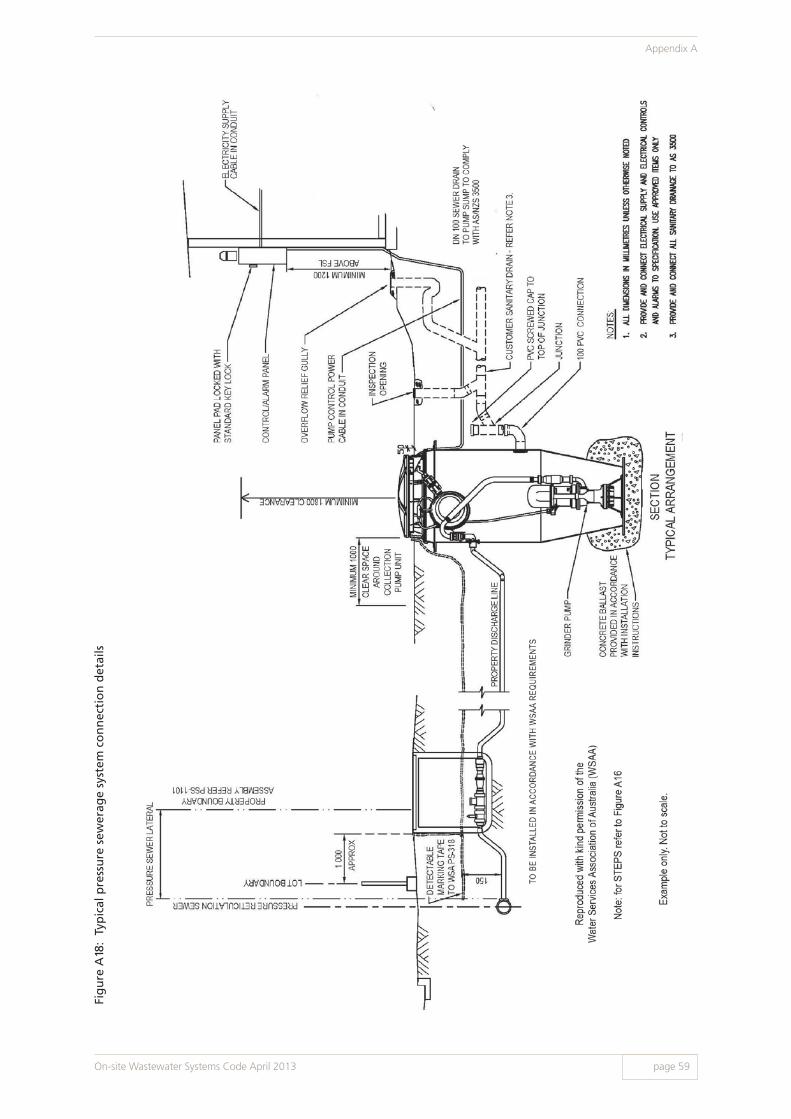
Fig
ure
A18
: Ty
pic
al p
ress
ure
sew
erag
e sy
stem
co
nn
ecti
on
det
ails
On-site Wastewater Systems Code April 2013 page 59
Appendix A

Fig
ure
A19
: Ty
pic
al v
acu
um
sew
erag
e co
llect
ion
ch
amb
er (
DN
105
0) d
etai
ls
On-site Wastewater Systems Code April 2013
Appendix A
page 60

Figure A20: Typical pump and pump chamber detail
On-site Wastewater Systems Code April 2013 page 61
Appendix A
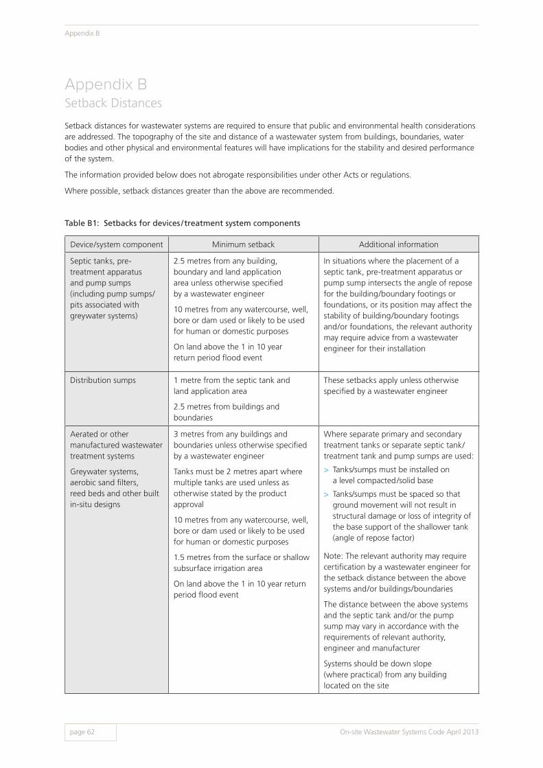
Appendix BSetback Distances
Setback distances for wastewater systems are required to ensure that public and environmental health considerations are addressed. The topography of the site and distance of a wastewater system from buildings, boundaries, water bodies and other physical and environmental features will have implications for the stability and desired performance of the system.
The information provided below does not abrogate responsibilities under other Acts or regulations.
Where possible, setback distances greater than the above are recommended.
Table B1: Setbacks for devices / treatment system components
Device/system component Minimum setback Additional information
Septic tanks, pre- treatment apparatus and pump sumps (including pump sumps/pits associated with greywater systems)
2.5 metres from any building, boundary and land application area unless otherwise specified by a wastewater engineer
10 metres from any watercourse, well, bore or dam used or likely to be used for human or domestic purposes
On land above the 1 in 10 year return period flood event
In situations where the placement of a septic tank, pre-treatment apparatus or pump sump intersects the angle of repose for the building/boundary footings or foundations, or its position may affect the stability of building/boundary footings and/or foundations, the relevant authority may require advice from a wastewater engineer for their installation
Distribution sumps 1 metre from the septic tank and land application area
2.5 metres from buildings and boundaries
These setbacks apply unless otherwise specified by a wastewater engineer
Aerated or other manufactured wastewater treatment systems
Greywater systems, aerobic sand filters, reed beds and other built in-situ designs
3 metres from any buildings and boundaries unless otherwise specified by a wastewater engineer
Tanks must be 2 metres apart where multiple tanks are used unless as otherwise stated by the product approval
10 metres from any watercourse, well, bore or dam used or likely to be used for human or domestic purposes
1.5 metres from the surface or shallow subsurface irrigation area
On land above the 1 in 10 year return period flood event
Where separate primary and secondary treatment tanks or separate septic tank/treatment tank and pump sumps are used:
> Tanks/sumps must be installed on a level compacted /solid base
> Tanks/sumps must be spaced so that ground movement will not result in structural damage or loss of integrity of the base support of the shallower tank (angle of repose factor)
Note: The relevant authority may require certification by a wastewater engineer for the setback distance between the above systems and/or buildings/boundaries
The distance between the above systems and the septic tank and/or the pump sump may vary in accordance with the requirements of relevant authority, engineer and manufacturer
Systems should be down slope (where practical) from any building located on the site
On-site Wastewater Systems Code April 2013
Appendix B
page 62

Table B2: Setbacks for land application systems from boundaries, buildings, wastewater devices, pools etc.
Land application system Minimum setback Additional information
Subsurface effluent disposal systems (e.g. soakage trenches and soakage beds)
2.5 metres from septic tanks, wastewater treatment systems, pump sumps, pre-treatment apparatus, allotment boundaries, diversion trenches, soakage trenches, ETA/ETS beds, or any other land application system
3 metres down slope from a building or a swimming pool, or where the site is flat, 3 metres from any point of the building or swimming pool
6 metres upslope from a building or swimming pool
These setbacks apply unless otherwise specified by a wastewater engineer
Shallow subsurface recycled water irrigation systems
On a flat or gently sloping site (i.e. gradient less than 1:100):
> 0.5 metres from allotment boundaries
> 1.5 metres from aerated or other wastewater treatment products, septic tanks or pump sumps
> 1.5 metres from buildings, including those erected on adjoining allotments
> 3 metres from swimming pools including surrounding paved areas
On a sloping site (i.e. gradient greater than 1:100):
> 0.5 metres down slope from allotment boundaries
> 1.5 metres up slope from allotment boundaries
> 1.5 metres down slope and 3 metres up slope from buildings, including those erected on adjoining allotments
> 3 metres up slope from a lower cut face/bench
> 3 metres down slope and 6 metres up slope from swimming pools including surrounding paved areas
These setbacks apply unless otherwise specified by a wastewater engineer
Note: Where it is intended to locate the shallow subsurface irrigation area up slope of a building, the wastewater engineer should be consulted to determine the likely impact on the building’s structure and the need for any additional requirements such as diversion trenches. Confirmation of the wastewater engineer’s requirements should be provided with the application
On-site Wastewater Systems Code April 2013 page 63
Appendix B

Land application system Minimum setback Additional information
Surface spray and drip recycled water irrigation systems
On a flat or gently sloping site (i.e. gradient less than 1:100):
> 0.5 metres from allotment boundaries
> 1.5 metres from aerated or other wastewater treatment products, septic tanks or pump sumps
> 1.5 metres from buildings, including those erected on adjoining allotments
> 3 metres from swimming pools including surrounding paved areas
On a sloping site (i.e. gradient greater than 1:100):
> 0.5 metres down slope from allotment boundaries
> 1.5 metres up slope from allotment boundaries
> 1.5 metres down slope and 3 metres up slope from buildings, including those erected on adjoining allotments
> 3 metres up slope from a lower cut face/bench
> 3 metres down slope and 6 metres up slope from swimming pools including surrounding paved areas
These setbacks apply unless otherwise specified by a wastewater engineer
For larger systems utilising spray irrigation, the relevant authority may increase setback distance requirements or request other measures to reduce the risk of public exposure to aerosols Note: Where it is intended to locate the surface irrigation area up slope of a building, the wastewater engineer should be consulted to determine the likely impact on the building’s structure and the need for any additional requirements such as diversion trenches. Confirmation of the wastewater engineer’s requirements should be provided with the application
On-site Wastewater Systems Code April 2013
Appendix B
page 64

Table B3: Setbacks for all land application systems from inland or coastal waters
Physical characteristics/site aspects
Minimum setback Additional information
Well, bore or dam used or likely to be used for human or domestic purposes
50 metres
Watercourse used or likely to be used for human or domestic purposes
50 metres Watercourse (see glossary for definition) identified on a current series 1:50,000 topographic map published by the Department of Environment, Water and Natural Resources
A watercourse is delineated as a blue line on a 1:50,000 topographic map. However, there are situations where a watercourse exists but is poorly delineated on the 1:50,000 topographic map or is obscured by other detail. Therefore it is important to ensure that the 50 metre setback is maintained
Water source used for agricultural, aquacultural or stock purposes
50 metres
Pool level for the River Murray and its lakes
100 metres and above the 1956 flood level
Disposal of effluent is not permitted within the 1956 River Murray and lakes flood zone
Mean high water spring along coastal foreshore areas
100 metres The setback distance of the land application system should be at least 100 metres from mean high water spring along coastal foreshore areas
On-site Wastewater Systems Code April 2013 page 65
Appendix B
Appendix COn-site Domestic Greywater Systems
1. What is greywater?Domestic wastewater is made up of greywater and blackwater:
> Greywater is wastewater generated from bathrooms (showers, baths, spas and hand basins), kitchens (sinks and dishwashers), and laundries (washing machines, troughs). Kitchen wastewater is generally excluded for use as greywater due to the presence of food and other solids, oils and grease which have the potential to cause blockages and odour issues unless subject to sufficient treatment.
> Blackwater is wastewater generated from toilets and urinals, and is excluded from the provisions of this appendix.
On average, each person generates approximately 150 L of wastewater per day. Of this, greywater flow constitutes approximately 100 L. For further information on flows, see section 5.2.
2. Greywater contaminantsThe quality of greywater is highly variable due to factors such as water source, efficiency of appliances and fixtures, individual habits, associated products (for example soaps, shampoos, detergents and other contaminants) and other site specific characteristics.
It is assumed by many that greywater is ‘clean’ and ‘safe for reuse’ as it does not contain blackwater. However, greywater may contain high levels of:
> Disease causing organisms (bacteria, viruses, protozoa, helminths)
> Suspended matter, organic matter, fats and oils, including but not limited to dirt, lint, food, hair, skin cells, fats and traces of faeces, urine and blood
> Chemicals derived from soaps, shampoos, dyes, mouthwash, toothpaste, detergents, bleaches, disinfectants, caustic dishwashing powders and other products (for example boron, phosphorus, sodium, ammonia and other nitrogen based compounds).
Management of greywater systems is essential to remove disease causing organisms, suspended and organic matter, as well as excess nutrients.
3. Manual bucketing and temporary diversionFor information on the requirements for manual bucketing onto lawn and garden areas using water from the bathroom or laundry, or temporary use of a hose manually fitted to the washing machine outlet hose, contact the DHA.
4. Permanent greywater systemsGreywater systems can be separated into two types:
> Greywater diversion devices divert greywater without storage or treatment
> Greywater treatment systems collect and treat greywater to a higher quality, often with storage.
Permanent greywater diversion devices and treatment systems are subject to the requirements of this Code. Where greywater systems are to be installed in areas administered by water industry entities, the relevant authorities must be contacted to determine any further requirements prior to installation.
5. Greywater irrigationUntreated and treated greywater must be irrigated via a dedicated land application area in accordance with this Code and the DHA product approval conditions.
On-site Wastewater Systems Code April 2013
Appendix C
page 66

Appendix DSuitable Plants for Recycled Water Irrigation
Note: This list is only intended to provide a selection of trees, shrubs and other plants which may be considered suitable for the land application area. Due to climatic and soil variations, it is essential that further investigations be made before finalising your plant choice to suit your particular locality and site conditions.
Trees
Botanical Name Common Name Approximate height in metres
Agonis flexuosa Willow Myrtle 5-6
Allocasuarina verticillata Drooping She Oak 3-5
Banksia spp. 3-10
Callistemon salignus White Bottlebrush 3-6
Callistemon viminalis Red Bottlebrush 3-6
Casuarina cunninghamiana River She Oak 6-10
Eucalyptus camaldulensis River Red Gum 15-20
Eucalyptus cosmophylla Cup Gum 5-6
Eucalyptus grandis Flooded Gum 10-20
Eucalyptus robusta Swamp Mahogany 6-9
Eucalyptus saligna Sydney Blue Gum 15-20
Hymenosporum flavum Native Frangipani 3-6
Melaleuca nesophila Western Tea Myrtle 2-4
Melaleuca quinquenervia Broad Paperbark 5-7
Syzygium paniculatum Bush Cherry 8-10
Tristaniopsis laurina Kanuka 3-5
On-site Wastewater Systems Code April 2013 page 67
Appendix D

Shrubs
Perennials /Ground Cover
Botanical Name Common Name Approximate height in metres
Abeliax grandiflora Abelia 2-3
Acacia floribunda Gossamer Wattle 2-4
Argyranthemum frutescena Marguerite Daisy 1
Chamelaucium uncinatum Geraldton Wax 2-4
Cyperus alternifolius Umbrella Grass 0.5-1
Cyperus papyrus Papyrus 1-2
Dryandra Formosa 1-3
Eremophila spp. 1-2
Grevillea spp. (apart from G. rosmarinifolia) 1-3
Hebe spp. Veronica 0.5-1
Iris pseudacorus Yellow Flag Iris 0.5-1
Melaleuca decussate Cross Leaved Honey Myrtle 1-2
Phormium tenax New Zealand Flax 2-2.5
Senna spp. (S. artemisioides) 1-3
Botanical Name Common Name Approximate height in metres
Aster novi-belgii Perennial Aster 0.5-1
Canna 1-2
Chrysanthemum maximum Shasta Daisy 1
Impatiens spp. 0.4
Salvia uliginosa Bog Salvia 0.4
Viola hederacea, eminens or sieberana 0.4
On-site Wastewater Systems Code April 2013
Appendix D
page 68

Climbers
Botanical Name Common Name Approximate height in metres
Bougainvillaea spp. Variable
Clematis microphylla Variable
Hardenbergia violacea Purple Coral Pea Variable
Hibbertia scandens Snake Vine Variable
Jasminum grandiflorum Variable
Jasminum officinale Common Jasmine Variable
Jasminum polyanthum Variable
Kennedia rubicunda Dusky Coral Pea Variable
Passiflora spp. Passion Flower Variable
Vitis coignetiae Glory Vine Variable
On-site Wastewater Systems Code April 2013 page 69
Appendix D

Appendix EHydraulic and BOD5 Loadings
Hyd
rau
lic a
nd
BO
D5
load
ing
s fo
r n
on
-res
iden
tial
pre
mis
esN
ote:
BO
D5
load
ing
rate
s ar
e fo
r se
ptic
tan
k ef
fluen
t. F
or r
aw s
ewag
e, t
hey
mus
t be
incr
ease
d by
40%
.
Prem
ises
Fixt
ure
sSl
ud
ge/
scu
m r
ate
D
aily
flo
w r
ate
BO
D5 lo
adin
g
Num
ber
of
pers
ons
or
as o
ther
wis
e in
dica
ted
Rate
: lit
res/
pers
on/y
ear
(L/p
/y) o
r as
ot
herw
ise
indi
cate
d
Num
ber
of
pers
ons
or
as o
ther
wis
e in
dica
ted
Rate
:lit
res/
pers
on/d
ay(L
/p/d
) or
as
othe
rwis
e in
dica
ted
Rate
: gra
ms/
pers
on/d
ay(g
/p/d
) or
as
othe
rwis
e in
dica
ted
P1S
P2D
FB
OD
5
Not
e: C
alcu
late
eac
h us
e an
d ad
d to
obt
ain
tota
l cap
acit
y
CA
RA
VA
N P
AR
KS
Perm
anen
t oc
cupa
tion
W.C
./ur
inal
, bas
in,
bath
/sho
wer
, la
undr
y, k
itche
n si
nk
tota
l num
ber
of
site
s x
3.5
p/s
ite80
tota
l num
ber
of
site
s x
3.5
p/s
ite15
050
Cas
ual o
ccup
atio
nW
.C./
urin
al, b
asin
, ba
th/s
how
er,
laun
dry,
kitc
hen
sink
aver
age
daily
nu
mbe
r of
site
s oc
cupi
ed o
ver
the
past
12
mon
ths
x 3.
5 p
/site
48
tota
l num
ber
of
site
s x
3.5
p/s
ite10
045
CH
ILD
DA
Y C
AR
E C
ENTR
ES
Can
teen
fac
ilitie
s
W.C
./ur
inal
, bas
in,
bath
/sho
wer
, la
undr
y, k
itche
n si
nk (t
ea s
ervi
ce
area
onl
y)
kitc
hen
sink
, di
shw
ashe
r
tota
l num
ber
of
child
ren
plus
sta
ff
tota
l num
ber
of
child
ren
plus
sta
ff
48
10
tota
l num
ber
of
child
ren
plus
sta
ff
tota
l num
ber
of
child
ren
plus
sta
ff
with
in-h
ouse
la
undr
y: 5
0,ex
tern
al la
undr
y se
rvic
e: 3
5
5
40 5
On-site Wastewater Systems Code April 2013
Appendix E
page 70
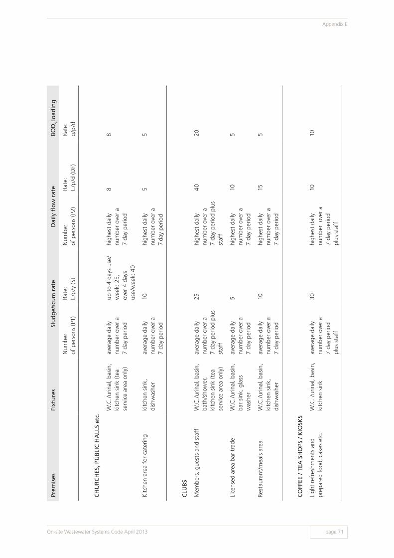
Prem
ises
Fixt
ure
sSl
ud
ge/
scu
m r
ate
D
aily
flo
w r
ate
BO
D5 lo
adin
g
Num
ber
of p
erso
ns (
P1)
Rate
:L
/p/y
(S)
Num
ber
of p
erso
ns (
P2)
Rate
: L
/p/d
(D
F)Ra
te:
g/p
/d
CH
UR
CH
ES, P
UB
LIC
HA
LLS
etc.
W.C
./ur
inal
, bas
in,
kitc
hen
sink
(tea
se
rvic
e ar
ea o
nly)
aver
age
daily
nu
mbe
r ov
er a
7
day
perio
d
up t
o 4
days
use
/w
eek:
25,
ov
er 4
day
s us
e/w
eek:
40
high
est
daily
nu
mbe
r ov
er a
7
day
perio
d
88
Kitc
hen
area
for
cat
erin
gki
tche
n si
nk,
dish
was
her
aver
age
daily
nu
mbe
r ov
er a
7
day
perio
d
10hi
ghes
t da
ily
num
ber
over
a
7 day
per
iod
55
CLU
BS
Mem
bers
, gue
sts
and
staf
fW
.C./
urin
al, b
asin
, ba
th/s
how
er,
kitc
hen
sink
(tea
se
rvic
e ar
ea o
nly)
aver
age
daily
nu
mbe
r ov
er a
7
day
perio
d pl
us
staf
f
25hi
ghes
t da
ily
num
ber
over
a7
day
perio
d pl
us
staf
f
4020
Lice
nsed
are
a ba
r tr
ade
W.C
./ur
inal
, bas
in,
bar
sink
, gla
ss
was
her
aver
age
daily
nu
mbe
r ov
er a
7
day
perio
d
5hi
ghes
t da
ily
num
ber
over
a7
day
perio
d
105
Rest
aura
nt/m
eals
are
aW
.C./
urin
al, b
asin
, ki
tche
n si
nk,
dish
was
her
aver
age
daily
nu
mbe
r ov
er a
7
day
perio
d
10hi
ghes
t da
ily
num
ber
over
a7
day
perio
d
155
CO
FFEE
/ TE
A S
HO
PS /
KIO
SKS
Ligh
t re
fres
hmen
ts a
nd
prep
ared
foo
d, c
akes
etc
.W
.C. /
urin
al, b
asin
, ki
tche
n si
nkav
erag
e da
ily
num
ber
over
a7
day
perio
d pl
us s
taff
30hi
ghes
t da
ily
num
ber
ove
r a
7 da
y pe
riod
plus
sta
ff
1010
On-site Wastewater Systems Code April 2013 page 71
Appendix E

Prem
ises
Fixt
ure
sSl
ud
ge/
scu
m r
ate
D
aily
flo
w r
ate
BO
D5 lo
adin
g
Num
ber
of p
erso
ns (
P1)
Rate
:L
/p/y
(S)
Num
ber
of p
erso
ns (
P2)
Rate
: L
/p/d
(D
F)Ra
te:
g/p
/d
CO
NST
RU
CTI
ON
CA
MPS
– T
EMPO
RA
RY
W.C
./ur
inal
, bas
in,
show
er, l
aund
ry,
kitc
hen
sink
, di
shw
ashe
r
tota
l num
ber
of
pers
ons
usin
g fa
cilit
ies
80 x
num
ber
of
year
s to
be
used
tota
l num
ber
of
pers
ons
usin
g fa
cilit
ies
150
50
FLA
TS /
UN
ITS
W.C
., ba
sin,
bat
h/
show
er, l
aund
ry,
kitc
hen
sink
, di
shw
ashe
r
2 pe
r be
droo
m o
r as
det
erm
ined
by
rele
vant
aut
horit
y
802
per
bedr
oom
or
as d
eter
min
ed b
y re
leva
nt a
utho
rity
150
50
HO
LID
AY
CA
MPS
e.g.
sco
ut, y
outh
and
chu
rch
cent
res
with
cas
ual o
ccup
atio
nW
.C./
urin
al, b
asin
, sh
ower
, kitc
hen
sink
, dis
hwas
her
tota
l num
ber
of b
eds
(sin
gle
equi
vale
nts)
48
high
est
daily
nu
mbe
r us
ing
faci
litie
s
100
50
Not
e: S
taff
and
/or
resi
dent
ial c
aret
aker
dat
a to
be
incl
uded
whe
re a
pplic
able
HO
SPIT
ALS
& N
UR
SIN
G H
OM
ES
Acc
omm
odat
ion
and
resi
dent
sta
ffW
.C./
urin
al, b
asin
, ba
th/s
how
er,
laun
dry,
kitc
hen
sink
, dis
hwas
her
tota
l num
ber
of
beds
plu
s re
side
nt
staf
f
80to
tal n
umbe
r of
be
ds p
lus
resi
dent
st
aff
150
200
Non
-res
iden
t st
aff
W.C
./ur
inal
, bas
in,
kitc
hen
sink
(tea
se
rvic
e ar
ea o
nly)
show
er
num
ber
of s
taff
pe
r sh
ift
x nu
mbe
r of
shi
fts
25nu
mbe
r of
sta
ff
per
shif
t x
num
ber
of s
hift
s
num
ber
of s
taff
pe
r sh
ift
x nu
mbe
r of
shi
fts
30 10
20 5
On-site Wastewater Systems Code April 2013
Appendix E
page 72

Prem
ises
Fixt
ure
sSl
ud
ge/
scu
m r
ate
D
aily
flo
w r
ate
BO
D5 lo
adin
g
Num
ber
of p
erso
ns (
P1)
Rate
:L
/p/y
(S)
Num
ber
of p
erso
ns (
P2)
Rate
: L
/p/d
(D
F)Ra
te:
g/p
/d
HO
TELS
/ M
OTE
LS /
LIV
E IN
CO
NFE
REN
CE
CEN
TRES
Acc
omm
odat
ion
W.C
./ur
inal
, bas
in,
bath
/sho
wer
, la
undr
y, k
itche
n si
nk
tota
l num
ber
of b
eds
(sin
gle
equi
vale
nts)
48
tota
l num
ber
of b
eds
(sin
gle
equi
vale
nts)
100
40
Resi
dent
sta
ff
W.C
./ur
inal
, bas
in,
bath
/sho
wer
, la
undr
y, k
itche
n si
nk
tota
l num
ber
of
live
in s
taff
80to
tal n
umbe
r of
liv
e in
sta
ff15
050
Bar
trad
eW
.C./
urin
al, b
asin
, ki
tche
n si
nk, g
lass
w
ashe
r
aver
age
daily
nu
mbe
r ov
er a
7
day
perio
d
5hi
ghes
t da
ily
num
ber
over
a
7 da
y pe
riod
1010
Din
ing
room
lo
unge
are
a no
n-re
side
nt u
se
W.C
./ur
inal
, bas
in,
kitc
hen
sink
, di
shw
ashe
r
aver
age
daily
nu
mbe
r ov
er a
7
day
perio
d
10hi
ghes
t da
ily
num
ber
over
a
7 da
y pe
riod
1510 20
Non
-res
iden
t st
aff
W.C
./ur
inal
, bas
in,
kitc
hen
sink
(tea
se
rvic
e ar
ea o
nly)
num
ber
of s
taff
pe
r sh
ift
x nu
mbe
r of
shi
fts
25nu
mbe
r of
sta
ff
per
shif
t x
num
ber
of s
hift
s
3020
show
ernu
mbe
r of
sta
ff
per
shif
t x
num
ber
of s
hift
s
105
On-site Wastewater Systems Code April 2013 page 73
Appendix E

Prem
ises
Fixt
ure
sSl
ud
ge/
scu
m r
ate
D
aily
flo
w r
ate
BO
D5 lo
adin
g
Num
ber
of p
erso
ns (
P1)
Rate
:L
/p/y
(S)
Num
ber
of p
erso
ns (
P2)
Rate
: L
/p/d
(D
F)Ra
te:
g/p
/d
MED
ICA
L C
ON
SULT
ING
RO
OM
S
Doc
tors
, den
tists
, st
aff
W.C
./ur
inal
, bas
in,
kitc
hen
sink
(tea
se
rvic
e ar
ea o
nly)
num
ber
of
pers
ons
usin
g sy
stem
per
shi
ft x
nu
mbe
r of
shi
fts
40nu
mbe
r of
pe
rson
s us
ing
syst
em p
er s
hift
x
num
ber
of s
hift
s
3020
show
ernu
mbe
r of
pe
rson
s us
ing
syst
em p
er s
hift
x
num
ber
of
shif
ts
105
Con
sulti
ng r
oom
spe
r co
nsul
ting
room
80 L
/con
sulti
ng
room
/yea
rpe
r co
nsul
ting
room
100
L/ c
onsu
lting
ro
om/d
ay40
g/c
onsu
lting
ro
om/d
ay
PUB
LIC
SW
IMM
ING
PO
OLS
Incl
udin
g ki
osk
e.g.
tak
e aw
ay f
ood
W.C
./ur
inal
, sh
ower
, bas
in,
kitc
hen
sink
(tea
se
rvic
e ar
ea o
nly)
aver
age
daily
nu
mbe
r ov
er a
7
day
perio
d
plus
sta
ff
20hi
ghes
t da
ily
num
ber
over
a
7 da
y pe
riod
pl
us s
taff
2015
PUB
LIC
TO
ILET
S
W.C
./ur
inal
, bas
inav
erag
e da
ily
num
ber
over
a
7 da
y pe
riod
20hi
ghes
t da
ily
num
ber
over
a
7 da
y pe
riod
510
show
erhi
ghes
t da
ily
num
ber
ove
r a
7 da
y pe
riod
105
On-site Wastewater Systems Code April 2013
Appendix E
page 74

Prem
ises
Fixt
ure
sSl
ud
ge/
scu
m r
ate
D
aily
flo
w r
ate
BO
D5 lo
adin
g
Num
ber
of p
erso
ns (
P1)
Rate
:L
/p/y
(S)
Num
ber
of p
erso
ns (
P2)
Rate
: L
/p/d
(D
F)Ra
te:
g/p
/d
RES
TAU
RA
NTS
No
liquo
r lic
ence
W.C
./ur
inal
, bas
in,
kitc
hen,
sin
k,
dish
was
her
aver
age
daily
nu
mbe
r ov
er a
7
day
perio
d pl
us s
taff
35hi
ghes
t da
ily
num
ber
over
a
7 da
y pe
riod
plus
sta
ff
1510
With
liqu
or li
cenc
eW
.C./
urin
al, b
asin
, ki
tche
n, s
ink,
di
shw
ashe
r, gl
ass
was
her
aver
age
daily
nu
mbe
r ov
er a
7
day
perio
d pl
us s
taff
35hi
ghes
t da
ily
num
ber
over
a
7 da
y pe
riod
plus
sta
ff
2015
RES
T H
OM
ES, B
OA
RD
ING
AN
D L
OD
GIN
G H
OU
SES
Acc
omm
odat
ion
and
resi
dent
sta
ffW
.C./
urin
al, b
asin
, ba
th/s
how
er,
laun
dry,
kitc
hen
sink
tota
l num
ber
of
bed
s (s
ingl
e eq
uiva
lent
) plu
s re
side
nt s
taff
80to
tal n
umbe
r of
be
ds p
lus
resi
dent
st
aff
(sin
gle
equi
vale
nts)
150
50
Non
res
iden
t st
aff
W.C
./ur
inal
, bas
in,
kitc
hen
sink
(tea
se
rvic
e on
ly)
num
ber
of s
taff
pe
r sh
ift
x nu
mbe
r of
shi
fts
25nu
mbe
r of
sta
ff
per
shif
t x
num
ber
of s
hift
s
3020
show
ernu
mbe
r of
sta
ff
per
shif
t x
num
ber
of s
hift
s
10
On-site Wastewater Systems Code April 2013 page 75
Appendix E

Prem
ises
Fixt
ure
sSl
ud
ge/
scu
m r
ate
D
aily
flo
w r
ate
BO
D5 lo
adin
g
Num
ber
of p
erso
ns (
P1)
Rate
:L
/p/y
(S)
Num
ber
of p
erso
ns (
P2)
Rate
: L
/p/d
(D
F)Ra
te:
g/p
/d
RO
AD
-HO
USE
S/SE
RV
ICE
STA
TIO
NS
Staf
fW
.C./
urin
al, b
asin
, ki
tche
n si
nk (t
ea
serv
ice
only
)
num
ber
of s
taff
pe
r sh
ift
x nu
mbe
r of
shi
fts
25nu
mbe
r of
sta
ff
per
shif
t x
num
ber
of s
hift
s
3020
show
ernu
mbe
r of
sta
ff
per
shif
t x
num
ber
of s
hift
s
105
Publ
ic t
oile
tsW
.C./
urin
al, b
asin
aver
age
daily
nu
mbe
r ov
er a
7
day
perio
d
20hi
ghes
t da
ily
num
ber
over
a
7 da
y pe
riod
510
show
erhi
ghes
t da
ily
num
ber
ove
r a
7 da
y pe
riod
105
Rest
aura
nt (t
ake
away
an
d si
t do
wn
mea
ls)
W.C
./ur
inal
, bas
in,
kitc
hen
sink
, di
shw
ashe
r
aver
age
daily
nu
mbe
r ov
er a
7
day
perio
d
10hi
ghes
t da
ily
num
ber
over
a
7 da
y pe
riod
1010
g p
er m
eal
SCH
OO
LS A
ND
KIN
DER
GA
RTE
NS
Incl
udin
g ki
osk
faci
litie
s e.
g. t
ake
away
foo
dW
.C./
urin
al, b
asin
, ki
tche
n si
nkto
tal n
umbe
r of
st
uden
ts p
lus
staf
f25
tota
l num
ber
of
stud
ents
plu
s st
aff
2015
show
er10
% o
f to
tal
num
ber
of
stud
ents
and
sta
ff
105
Can
teen
fac
ilitie
s (e
.g. p
late
d ho
t an
d co
ld m
eals
)ki
tche
n si
nk,
dish
was
her
tota
l num
ber
of
stud
ents
plu
s st
aff
10to
tal n
umbe
r o
f st
uden
ts p
lus
staf
f5
5
On-site Wastewater Systems Code April 2013
Appendix E
page 76
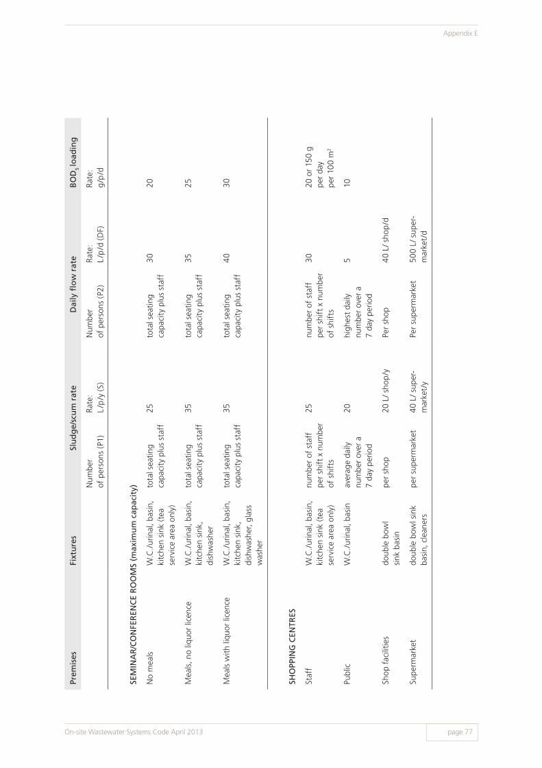
Prem
ises
Fixt
ure
sSl
ud
ge/
scu
m r
ate
D
aily
flo
w r
ate
BO
D5 lo
adin
g
Num
ber
of p
erso
ns (
P1)
Rate
:L
/p/y
(S)
Num
ber
of p
erso
ns (
P2)
Rate
: L
/p/d
(D
F)Ra
te:
g/p
/d
SEM
INA
R/C
ON
FER
ENC
E R
OO
MS
(max
imu
m c
apac
ity)
No
mea
lsW
.C./
urin
al, b
asin
, ki
tche
n si
nk (t
ea
serv
ice
area
onl
y)
tota
l sea
ting
capa
city
plu
s st
aff
25to
tal s
eatin
g ca
paci
ty p
lus
staf
f30
20
Mea
ls, n
o liq
uor
licen
ceW
.C./
urin
al, b
asin
, ki
tche
n si
nk,
dish
was
her
tota
l sea
ting
capa
city
plu
s st
aff
35to
tal s
eatin
g ca
paci
ty p
lus
staf
f35
25
Mea
ls w
ith li
quor
lice
nce
W.C
./ur
inal
, bas
in,
kitc
hen
sink
, di
shw
ashe
r, gl
ass
was
her
tota
l sea
ting
capa
city
plu
s st
aff
35to
tal s
eatin
g ca
paci
ty p
lus
staf
f40
30
SHO
PPIN
G C
ENTR
ES
Staf
fW
.C./
urin
al, b
asin
, ki
tche
n si
nk (t
ea
serv
ice
area
onl
y)
num
ber
of s
taff
pe
r sh
ift
x nu
mbe
r of
shi
fts
25nu
mbe
r of
sta
ff
per
shif
t x
num
ber
of s
hift
s
3020
or
150
g
per
day
per
100
m2
Publ
icW
.C./
urin
al, b
asin
aver
age
daily
nu
mbe
r ov
er a
7
day
perio
d
20hi
ghes
t da
ily
num
ber
over
a
7 da
y pe
riod
510
Shop
fac
ilitie
sdo
uble
bow
l si
nk b
asin
per
shop
20 L
/ sho
p/y
Per
shop
40 L
/ sho
p/d
Supe
rmar
ket
doub
le b
owl s
ink
basi
n, c
lean
ers
per
supe
rmar
ket
40 L
/ sup
er-
mar
ket/
yPe
r su
perm
arke
t50
0 L/
sup
er-
mar
ket/
d
On-site Wastewater Systems Code April 2013 page 77
Appendix E
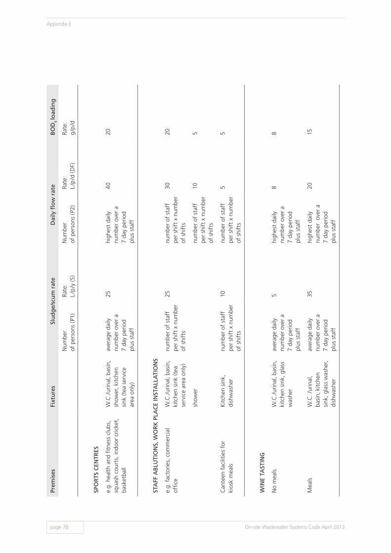
Prem
ises
Fixt
ure
sSl
ud
ge/
scu
m r
ate
D
aily
flo
w r
ate
BO
D5 lo
adin
g
Num
ber
of p
erso
ns (
P1)
Rate
:L
/p/y
(S)
Num
ber
of p
erso
ns (
P2)
Rate
: L
/p/d
(D
F)Ra
te:
g/p
/d
SPO
RTS
CEN
TRES
e.g.
hea
lth a
nd fi
tnes
s cl
ubs,
sq
uash
cou
rts,
indo
or c
ricke
t,
bask
etba
ll
W.C
./ur
inal
, bas
in,
show
er, k
itche
n si
nk (t
ea s
ervi
ce
area
onl
y)
aver
age
daily
nu
mbe
r ov
er a
7
day
perio
d
plus
sta
ff
25hi
ghes
t da
ily
num
ber
over
a
7 da
y pe
riod
pl
us s
taff
4020
STA
FF A
BLU
TIO
NS,
WO
RK
PLA
CE
INST
ALL
ATI
ON
S
e.g.
fac
torie
s, c
omm
erci
al
offic
eW
.C./
urin
al, b
asin
, ki
tche
n si
nk (t
ea
serv
ice
area
onl
y)
num
ber
of s
taff
pe
r sh
ift
x nu
mbe
r of
shi
fts
25nu
mbe
r of
sta
ff
per
shif
t x
num
ber
of s
hift
s
3020
show
ernu
mbe
r of
sta
ff
per
shif
t x
num
ber
of s
hift
s
105
Can
teen
fac
ilitie
s fo
r
kios
k m
eals
Kitc
hen
sink
, di
shw
ashe
rnu
mbe
r of
sta
ff
per
shif
t x
num
ber
of s
hift
s
10nu
mbe
r of
sta
ff
per
shif
t x
num
ber
of s
hift
s
55
WIN
E TA
STIN
G
No
mea
lsW
.C./
urin
al, b
asin
, ki
tche
n si
nk, g
lass
w
ashe
r
aver
age
daily
nu
mbe
r ov
er a
7
day
perio
d
plus
sta
ff
5hi
ghes
t da
ily
num
ber
over
a7
day
perio
d
plus
sta
ff
88
Mea
lsW
.C. /
urin
al,
basi
n, k
itche
n si
nk, g
lass
was
her,
dish
was
her
aver
age
daily
nu
mbe
r ov
er a
7 da
y pe
riod
plus
sta
ff
35hi
ghes
t da
ily
num
ber
ove
r a
7 da
y pe
riod
plus
sta
ff
2015
On-site Wastewater Systems Code April 2013
Appendix E
page 78

Prem
ises
Fixt
ure
sSl
ud
ge/
scu
m r
ate
D
aily
flo
w r
ate
BO
D5 lo
adin
g
Num
ber
of p
erso
ns (
P1)
Rate
:L
/p/y
(S)
Num
ber
of p
erso
ns (
P2)
Rate
: L
/p/d
(D
F)Ra
te:
g/p
/d
SPO
RTS
CEN
TRES
e.g.
hea
lth a
nd fi
tnes
s cl
ubs,
sq
uash
cou
rts,
indo
or c
ricke
t,
bask
etba
ll
W.C
./ur
inal
, bas
in,
show
er, k
itche
n si
nk (t
ea s
ervi
ce
area
onl
y)
aver
age
daily
nu
mbe
r ov
er a
7
day
perio
d
plus
sta
ff
25hi
ghes
t da
ily
num
ber
over
a
7 da
y pe
riod
pl
us s
taff
4020
STA
FF A
BLU
TIO
NS,
WO
RK
PLA
CE
INST
ALL
ATI
ON
S
e.g.
fac
torie
s, c
omm
erci
al
offic
eW
.C./
urin
al, b
asin
, ki
tche
n si
nk (t
ea
serv
ice
area
onl
y)
num
ber
of s
taff
pe
r sh
ift
x nu
mbe
r of
shi
fts
25nu
mbe
r of
sta
ff
per
shif
t x
num
ber
of s
hift
s
3020
show
ernu
mbe
r of
sta
ff
per
shif
t x
num
ber
of s
hift
s
105
Can
teen
fac
ilitie
s fo
r
kios
k m
eals
Kitc
hen
sink
, di
shw
ashe
rnu
mbe
r of
sta
ff
per
shif
t x
num
ber
of s
hift
s
10nu
mbe
r of
sta
ff
per
shif
t x
num
ber
of s
hift
s
55
WIN
E TA
STIN
G
No
mea
lsW
.C./
urin
al, b
asin
, ki
tche
n si
nk, g
lass
w
ashe
r
aver
age
daily
nu
mbe
r ov
er a
7
day
perio
d
plus
sta
ff
5hi
ghes
t da
ily
num
ber
over
a7
day
perio
d
plus
sta
ff
88
Mea
lsW
.C. /
urin
al,
basi
n, k
itche
n si
nk, g
lass
was
her,
dish
was
her
aver
age
daily
nu
mbe
r ov
er a
7 da
y pe
riod
plus
sta
ff
35hi
ghes
t da
ily
num
ber
ove
r a
7 da
y pe
riod
plus
sta
ff
2015
Appendix FConnection of the On-site Wastewater System to a CWMS
The following requirements outline the specific provisions for connecting on-site wastewater systems to the various types of CWMS.
Connection requirements for a CWMS differ according to the type of system. Types of CWMS systems are broadly described below:
1. Septic tank effluent drainage scheme (STEDS)The drains from the premises discharge to a septic tank of an approved type and capacity before connection to the CWMS (refer to appendix A figure A15). Pre-treatment of any trade waste may be required prior to any connection to a septic tank (see also section 3.6.4.).
2. Septic tank effluent pumping scheme (STEPS)In addition to discharging to a septic tank of an approved type and capacity, connection to a STEPS requires the provision of pumping chamber and pump to discharge the wastewater to the CWMS (refer to appendix A figure A16).
3. Sewerage systemThe property sewer drain can discharge directly to the CWMS connection point without the use of a septic tank (refer to appendix A figure A17). However, in some cases treatment tanks or pre-treatment apparatus may be required for specific wastes, for example a grease arrestor. Where the connection cannot be made by gravity, a pumping system is required.
4. Pressure sewerage system (PSS)The drains from the premises discharge into a pumping chamber and the sewage is pumped to the CWMS connection point (refer to appendix A figure A 18).
5. Vacuum sewerage systemThe property connections discharge into a collection chamber and the contents are removed by negative pressure into collecting mains. The discharge from the premises to the property collecting chambers is normally by gravity flow but in some cases it may be by pumping (refer to appendix A figure A19).
On-site Wastewater Systems Code April 2013 page 79
Appendix F
F1 General Provisions
F1.1 Sanitary plumbing and drainageThe sanitary plumbing and drainage system for premises connected to a CWMS must be installed in accordance with AS/NZS 3500, the Plumbing Code of Australia (PCA) and the SA variations and additions in Appendix A of the PCA unless otherwise permitted by this Code and/or the relevant authority (see also chapter 4 and section F1.4).
F1.2 Septic tank sizing and positioningSeptic tanks must be sized in accordance with this Code (see section 6.1). All septic or treatment tanks and/or pump chambers are to be positioned in accordance with this Code or as required by the relevant authority.
F1.3 Septic tank access shaftsAll new treatment tanks are required to have the access openings installed in accordance with this Code (see section 7.1).
F1.4 Existing plumbing and septic tanks connecting to a CWMSIn some older premises, the standards for the sanitary plumbing and drainage system may vary from the current requirements. The relevant authority may require sections of the existing sanitary plumbing and drainage to be upgraded or require inspections and/or appropriate testing to be carried out to determine the suitability of the system for connection to the CWMS.
Existing septic tanks may be connected to a CWMS subject to the following requirements:
> The relevant authority may require replacement of existing septic tanks and/or other treatment tanks found to be in a poor state of repair, where the tank capacity is inadequate, or will contribute to an increased hydraulic or biological load or other risk to any components of the CWMS.
> All existing septic tanks designed on the sizing criteria in place prior to 1988 are to be subject to inspection and testing before being authorised to connect to the CWMS. This may include a report from a wastewater engineer.
> Tanks are to be exposed and opened for inspection to determine condition and capacity, be desludged and cleaned out, and repaired where necessary as determined by the relevant authority, before being connected to the CWMS.
> The relevant authority can, by notice or as a condition of approval to connect to the CWMS, require an existing tank to be modified and/or repaired in accordance with the requirements of this Code.
> In all cases of a STEPS connection to the CWMS, the property septic or treatment tanks will discharge into the STEPS pumping chamber located on each allotment. Pumping from a septic tank, treatment tank, device or apparatus directly to the CWMS connection is not permitted.
> The contents of a desludged tank, or the contents of the on-site land application area, must be disposed of in accordance with the relevant authority’s requirements and must not be discharged into the CWMS.
F1.5 Disconnection of an existing septic tankWhere an existing septic tank is to be disconnected, the relevant authority may, where applicable, stipulate conditions as to its retention in the ground, for example contents pumped out and taken to a facility complying with the relevant authority’s requirements, tank crushed on site and backfilled with specified material, or the tank is removed and disposed of offsite.
F1.6 Existing land application areasExisting on-site land application systems, for example soakage trenches, beds, wells or pits must not be connected to the CWMS. It is not normally necessary to backfill disused on-site subsurface disposal systems unless they are dangerous, create an insanitary condition or do not meet other relevant authority requirements. Connecting drains are not permitted to pass through septic or treatment tanks, soakage wells, similar structures or other unstable areas unless meeting the requirements of AS/NZS 3500.
On-site Wastewater Systems Code April 2013
Appendix F
page 80

F1.7 Provisions relating to existing wastewater treatment systemsSome premises may have an existing wastewater treatment system or other approved product treating wastewater to standard suitable for reuse in accordance with this Code.
The relevant authority may grant conditional approval for the retention of this system for continued application of recycled water to a land application area or part thereof. Where retention of the system is permitted, it may be subject to such conditions as the relevant authority requires which may include:
> The system is a complying system
> Testing of the system on a regular basis to ensure compliance with all relevant standards
> The system has the capacity to treat all wastes from the sanitary plumbing and drainage system installed within the premises
> Maintenance of the system in accordance with the relevant authority’s requirements to ensure the system operates under optimum operating conditions
> Provision of maintenance certificates
> Desludging of the septic tank/treatment tank at specified frequencies
> All year round surface irrigation onto the site
> Summer irrigation onto the site, with winter discharge to the CWMS. Where winter discharge to the CWMS is permitted, it will be necessary to continue to maintain the wastewater treatment system in accordance with the manufacturer’s requirements.
Note: Failure to correctly operate and maintain the system may require the discharge from the septic tank to be connected directly to the CWMS and the remainder of the system de-commissioned.
F1.8 Provisions relating to other types of systemsThe relevant authority may, where another type of system is installed such as a composting toilet and a greywater wastewater system, require the system or part thereof to be connected to the CWMS. The relevant authority may impose such conditions as it deems appropriate within the meaning of the Wastewater Regulations and/or Local Government Act requirements.
F1.9 Containment for off-site disposalWhere the wastewater is not permitted to be discharged to the CWMS, e.g. trade wastes, the relevant authority will require that an on-site holding tank be provided. In such cases the relevant authority will require that the contained waste be removed by a licensed contractor for offsite disposal at a suitable location as required by the relevant authority and/or other agencies such as the Environment Protection Authority. The on-site holding tank must be a product approved by the Minister and installed in accordance with relevant authority requirements.
F2 Connection to a Septic Tank Effluent Drainage Scheme (STEDS)
Inspection shafts on drains prior to the septic tank or the treatment tank are to be located in accordance with AS/NZS 3500.
Discharge from all fixtures within the premises served by the connection shall pass through an approved septic tank unless otherwise permitted by the relevant authority. All trade waste connections to a CWMS must be approved by the relevant authority. Where a pre-treatment tank or apparatus for treatment of trade wastes (e.g. grease arrestor) is required to be installed, it must be fitted prior to the septic tank unless otherwise permitted by the relevant authority. Refer to appendix A figure A15.
Connecting drains from the septic tank(s) to the STEDS and inspection shafts shall be installed in accordance with AS/NZS 3500, the Plumbing Code of Australia (PCA) and the SA variations and additions in Appendix A of the PCA unless otherwise specified by this Code or as otherwise permitted by the relevant authority.
On-site Wastewater Systems Code April 2013 page 81
Appendix F

The connecting drain from a septic tank (which shall not be less than DN100), is to be laid with an even fall and have a minimum grade of 1% unless otherwise permitted by the relevant authority.
All inspection shafts on the STEDS property connection drain within the property and the property connecting drains must be maintained so as to permit access by the relevant authority for inspection, maintenance or monitoring progress.
All inspection shafts are to be constructed so as to terminate at the finished surface ground level and be provided with a concrete base and an approved threaded access cap, concrete block and covers, to ensure access to the drain for inspection, maintenance and/or monitoring purposes.
All concrete blocks and covers are to be installed and supported in such a manner as to prevent transmission of live loads onto the drain or the riser shaft.
Induct vents are not required on the connecting drain from the septic tank to the STEDS. Existing induct vents must be removed and the opening sealed in accordance with the relevant authority’s requirements, or alternatively it can be converted to a DN100 inspection shaft if located in accordance with AS/NZS 3500.
F2.1 Pumped connectionsWhere the authority STEDS connection point provided to the property is at a level higher than the septic or treatment tank outlet, it will be necessary to pump the effluent to the connection. In these circumstances, it will be necessary to install a pump chamber and pump as detailed in section F9. The discharge from all sanitary fixtures and other plumbing fittings shall pass through an approved septic tank before discharging into the pump chamber. For systems incorporating trade waste flows, further treatment may be necessary. Connections of trade waste flows to the CWMS must be approved by the relevant authority.
F3 Connection to Septic Tank Effluent Pumping Scheme (STEPS)
Inspection shafts on drains prior to the septic tank or the treatment tank are to be located in accordance with AS/NZS 3500. Septic tanks are to be sized in accordance with this Code.
Discharge from all fixtures within the premises served by the connection shall pass through an approved septic tank unless otherwise permitted by the relevant authority. All trade waste connections to a CWMS must be approved by the relevant authority. Where a pre-treatment tank or apparatus for treatment of trade wastes is required to be installed (e.g. grease arrestor), it must be fitted prior to the septic tank unless otherwise permitted by the relevant authority.
Connecting drains from the septic tank(s) to the pump sump shall be installed in accordance with AS/NZS 3500, the Plumbing Code of Australia (PCA) and the SA variations and additions in Appendix A of the PCA, unless otherwise specified by this Code or as otherwise permitted by the relevant authority.
Sizing of the property pump sumps shall be in accordance with section F9 of this Code or as otherwise permitted by the relevant authority.
Connection to a STEPS shall be carried out in accordance with the relevant sections of the Pressure Sewerage Code of Australia WSA 07 (see appendix A figures A16 and A18). Note that for a STEPS, a septic tank will be required unless otherwise permitted by the relevant authority (see above).
As a condition of approval the relevant authority may require that all rising mains on the property be tested and inspected prior to backfilling.
Where the rising main changes direction, a concrete thrust block or other suitable measures are required to provide adequate support to prevent movement of the bend.
All check valve boxes and covers are to be installed and supported in such a manner as to prevent transmission of live loads onto the rising main and connection.
An induct vent or air admittance valve is required on the pump sump in accordance with AS/NZS 3500.
On-site Wastewater Systems Code April 2013
Appendix F
page 82
F4 Connection to a Sewerage System
Connecting drains from the sanitary fixtures and plumbing to the authority sewerage system connection point shall be installed in accordance with AS/NZS 3500, the Plumbing Code of Australia (PCA) and the SA variations and additions in Appendix A of the PCA unless otherwise permitted by the relevant authority. Trade waste discharges must be approved by the relevant authority. Refer to appendix A figure A17.
F5 Connection to a Pressure Sewerage System (PSS)
Sanitary plumbing and drainage requirements upstream from the pumping chamber to the premises are to be installed in accordance with AS/NZS 3500, the Plumbing Code of Australia (PCA) and the SA variations and additions in Appendix A of the PCA unless otherwise permitted by the relevant authority. Trade waste discharges must be approved by the relevant authority.
Connection to a PSS shall be carried out in accordance with the Pressure Sewerage Code of Australia WSA 07 (see appendix A figure A18).
Sizing of property pump sumps shall be in accordance with section F9 of this appendix or as otherwise permitted by the relevant authority and be vented in accordance with AS/NZS 3500.
As a condition of approval, the relevant authority may require that all rising mains on the property be tested and inspected prior to backfilling.
Where the rising main changes direction, a concrete thrust block or other suitable measures are required to provide adequate support to prevent movement of the bend.
F6 Connection to a Vacuum Sewerage System
Connecting drains from the sanitary plumbing fixtures to the vacuum collection chamber serving the property shall be installed in accordance with AS/NZS 3500, the Plumbing Code of Australia (PCA) and the SA variations and additions in Appendix A of the PCA unless otherwise permitted by the relevant authority. Trade waste discharges must be approved by the relevant authority.
Venting of drains connected to vacuum chambers must be carried out in accordance with AS/NZS 3500 unless otherwise permitted by the relevant authority (see appendix A figure A19).
Property connections to the vacuum CWMS (including vacuum collection chamber requirements) are to be carried out in accordance with the Vacuum Sewerage Code of Australia WSA 06 unless otherwise permitted by the relevant authority.
All inspection shafts on the property connecting drains must be maintained so as to permit access by the relevant authority for inspection, maintenance or monitoring purposes.
All concrete blocks and covers are to be installed and supported in such a manner as to prevent transmission of live loads onto the drain or the riser shaft.
F7 Testing of Connecting Drains or Pipework
As a condition of approval, the relevant authority can require that all drains and/or connecting pipes be tested and be inspected before being backfilled in accordance with AS/NZS 3500. Where water testing is carried out, the drain is to remain full until the backfill process is completed.
On-site Wastewater Systems Code April 2013 page 83
Appendix F
F8 Maintenance of Septic Tanks, Treatment Tanks and/or Pumping Chambers
To ensure the CWMS operation is not jeopardised and is correctly maintained, the relevant authority may, by notice, require maintenance of a wastewater system connected to the scheme. This maintenance may include regular desludging of the septic tanks, treatment tanks or pumping chambers.
The relevant authority may determine the frequency of septic tank desludging which can vary according to the design parameters of the CWMS and its operating and maintenance requirements.
F8.1 Commercial use wastewater systems or other premisesFor grease and oil arrestors, settlement and/or other non-standard treatment tanks, devices or appurtenances, the relevant authority may impose stringent trade waste operating and maintenance conditions of approval. This may include pumping out at more frequent intervals to prevent risk or harm to the CWMS (collection, treatment, disposal or reuse system). In such cases cart notes confirming the frequency of pump out intervals and quantity shall be provided to the relevant authority. Penalties apply where an operator fails to adequately maintain a wastewater system and its operation impacts adversely on the CWMS. The penalties may include rectification costs and disconnection from the CWMS.
F8.2 General maintenance provisionsAfter cleaning out and inspection where required by the relevant authority, the septic or treatment tank shall be filled with water to a level above the transfer openings located in the division wall or at least to half the operating liquid depth. In some areas it may be necessary to immediately fill the tanks to the operating level to prevent displacement by fresh, saline or tidal ground water. Special conditions may apply to septic and treatment tanks constructed of lightweight materials and owners/operators should refer to the Minister’s approval conditions and/or the manufacturer’s recommendations.
It is not necessary to remove all of the sludge scum from the domestic use septic tanks as a small amount of residue left on the walls and the floor will assist with the re-seeding and normal operation of the septic tank.
In the case of a domestic septic tank, some odour may be experienced during the initial operation of the tank after cleaning out. For typical domestic septic tanks, the addition of 5 kg of lime in solution form, or the use of proprietary enzymes in accordance with the manufacturer’s directions, may assist with the correct functioning of the treatment tank. It may be necessary to repeat the lime dosing weekly for several weeks to obtain the optimum operating conditions.
On-site Wastewater Systems Code April 2013
Appendix F
page 84

F9 Provisions Relating to Pumping Chambers and Pumps
DESIGN, INSTALLATION AND PERFORMANCE REQUIREMENTS FOR PUMP CHAMBERS AND PUMPS (Refer to appendix A figure A 20)
Access cover The top cover of the pump chamber must finish at least 50 mm above the finished ground or surface level, or if at surface level be sealed to prevent ingress of surface water. The top of the pump chamber must be provided with a removable cover providing sufficient access for operation and maintenance requirements and when fitted be watertight. The access cover must also be secured in such a manner as to be child proof.
Alarm systems The pump must be provided with an audible and visible alarm system, which is activated when the liquid reaches the high water level. Muting facilities may be provided for the audible component. The location of the alarm system is to be such that it will provide indication to the occupants of the premises of an alarm condition under normal occupancy conditions. The relevant authority may require duplicate indicators e.g. one internally within the premises and one external to the premises in cases where the premises are not attended 24 hours a day.
Construction Each unit must be manufactured from a material suitable for its intended use. It must not be subject to structural failure, distortion under hydrostatic or other environmental pressures when empty or full, and/or as approved by the Minister.
Increment risers Unless otherwise permitted by the relevant authority, any approved increment risers necessary to raise the pump chamber to the required surface level shall be installed with interlocking joints, and be sealed against the ingress of water with an approved jointing compound.
Installation and operation
Each pump sump (including increment risers) must be a DHA approved product. Each unit offered for sale must be accompanied by a comprehensive set of manufacturer’s installation and operation instructions and be installed to comply with the manufacturer’s requirements. Where necessary, pump chambers must be protected from flotation.
Electrical wiring The electrical wiring and installation of the switchgear and pumps shall be carried out by an electrician licensed pursuant to the Plumbers, Gasfitters and Electricians Act 1995 and all work shall be in accordance with the supply authority requirements. Electrical systems and surface mounted or submersible pumps shall incorporate waterproof connections and be rendered safe and child proof.
Emergency capacity The minimum effective emergency storage capacity shall be 500 L or 50% of the daily flow, whichever is the greater, unless otherwise permitted by the relevant authority.
Occupational Health & Safety
Any work carried out within a pump chamber is to be undertaken with regard to a confined and hazardous location and in compliance with Occupational Health, Safety and Welfare provisions.
Pipework connections Connections to the pump chamber are to be made in accordance with the manufacturer’s instructions and the requirements of the relevant authority. Pipework connections are not permitted within or through the top cover of the pump chamber unless specifically permitted by the relevant authority. Under no circumstances will pipework, electrical connections, vents etc. be permitted in the access opening cover.
Pumps Pumps must be of a kind suitable for the required duty and operating environment and may be either a submersible or surface mounted type. When used for pumping sewage, macerator type pumps are to be used and these must be sized to handle a minimum sized solid object under normal operating conditions. The design of any pump system must be such that the full load can be accommodated after a power outage.
On-site Wastewater Systems Code April 2013 page 85
Appendix F

Pump capacity The pump capacity shall be designed to discharge the maximum daily flow against any physical or imposed head. For commercial or other premises the hydraulic flow is to be determined in accordance with the design parameters of this Code. In the case of STEPS and PSS, the pump capacity/specification shall be in accordance with the design engineers’ requirements.
Pump connections All connections to the pump are to be such as to enable disconnection from suction and/or discharge lines by means of a union or flange type couplings. The pump is to be statically mounted and permanently wired to operate automatically.
Pumps for larger systems
In cases where the premises are of a commercial or supported residential type premises and serving more than 10 persons or the hydraulic flow into the pump chamber exceeds 1500 L per day, the relevant authority can require duty and standby pumps to be installed and wired to alternate the duty cycle automatically. The electrical controls shall facilitate operation of the standby pump in the event of the duty pump malfunction and provide the necessary alarm condition to warn of a pump malfunction.
Setback distances See Appendix B.
STEPS and PSS In the case of a STEPS or a PSS, scheme design engineers or other persons accepted by the relevant authority shall specify the pumping system requirements.
Surface mounted pumps
In the case where the pump is surface mounted, it shall be contained within a waterproof and childproof ventilated housing to protect the pump, motor and electrical controls from adverse ambient conditions. The pump housing is to be protected against damage from vehicles and/or other impacts.
Vehicular loadings If in a vehicle access area, the pump chamber is to be constructed so as to accommodate vehicle loadings likely to be encountered, otherwise the area must be protected with bollards to prevent load onto the pump chamber cover.
Venting Induct vents or air admittance valves for the pump chamber are to be installed in accordance with AS/NZS 3500 – unless otherwise permitted by the relevant authority.
On-site Wastewater Systems Code April 2013
Appendix F
page 86
Appendix GDual Water Supply Systems for Premises
Dual water supply systems consist of two water supplies being provided to consumers. One main conveys potable water while the other supplies appropriately treated non-drinking water.
DHA approval will be required for any recycled water supply system utilising treated wastewater including the treatment plant and the infrastructure necessary to convey it to individual premises. For information on these systems, contact the DHA.
Individual connections to dual water supply systems shall be carried out in accordance with:
> Dual Water Supply Systems First Edition Version 1.2. A Supplement to the Water Supply Code of Australia WSA 03-2002
> AS/NZS 3500.1 Section 9 Non-Drinking Water Services
> Any further requirements of the relevant authority.
Note that as part of the required risk management plan for the recycled water supply, service providers are required to provide training/information to homeowners and contractors which will include:
> Information on connection to the scheme and notification processes for inspections
> Information on the responsibilities of homeowners/contractors and permitted uses of the recycled water supply including health and safety information and contact details of responsible persons
> Required auditing procedures for installed systems.
On-site Wastewater Systems Code April 2013 page 87
Appendix G

Prepared by:
Wastewater Management SectionHealth ProtectionPublic Health and Clinical SystemsDepartment for Health and AgeingPO Box 6, Rundle Mall SA 5000, Australia
ISBN: 978-1-74243-510-7
www.ausgoal.gov.au/creative-commons
Preface This Department for Health and Ageing code has been prepared as the “On-site Wastewater Systems Code” pursuant to the South Australian Public Health (Wastewater) Regulations 2013.
© Department for Health and Ageing, Government of South Australia. All rights reserved. April 2013.