Embed Size (px)
Citation preview

KfK 2616März 1978
On elastic structuralelements for Nuclear
Reactors.A critical review
F. PovoloInstitut für Material- und Festkörperforschung
Kernforschungszentrum Karlsruhe

Als Manuskript vervielfältigt
Für diesen Bericht behalten wir uns alle Rechte vor
KERNFORSCHUNGSZENTRUM KARLSRUHE GMBH

KERNFORSCHUNGS ZENTRUM KARLSRUHE
Institut für Material- und Festkörperforschung
KfK 2616
On elastic structural elements for Nuclear Reactors.
A critical review.
by
F. Povolo:~
Kernforschungszentrum Karlsruhe G.m.b.H., Karlsruhe
:~ On leave from: Comision Nacional de Energia Atomica,Dto. Materiales Buenos Aires, Argentina.


Sununary
The in-pile stress-relaxation behaviour of the materials usually
employed for the elastic structural elements, in nuclear reactors,
is critically reviewed and the results are compared with those
obtained in conunercial zirconium alloys irradiated under similar
conditions.
Finally, it is shown that, under certain conditions, some zirconium
alloys may be used as an alternative material for these structural
elements.
Elastische Strukturelemente nuklearer Reaktoren
- Eine kritische Übersicht -
Zusammenfassung
Es wird eine kritische Übersicht des in-pile Spannungsrelaxations
verhaltens von Werkstoffen gegeben, die gewöhnlich als elastische
Strukturmaterialien in nuklearen Reaktoren verwendet werden.
Ein Vergleich mit dem Verhalten kommerzieller Zirkonlegierungen
- unter ähnlichen Bestrahlungsverhältnissen - zeigt, daß in be
stinunten Fällen einige dieser Zirkonlegierungen als alternative
Werkstoffe für elastische Strukturelemente in Frage konunen.

Introduction
Several elastic structural elements, mainly springs and spacers,
are included in the fuel bundles of nuclear power plants. These
elements are made with Inconel 718 and Stainless Steel (1.4980
= A 286 in the case of Atucha) and even if they show very good
mechanical properties, under servicing conditions, have the disad
vantage of a large neutron absortion reducing considerably the
efficiency of the reactor. In fact, the cross-section for neutron
absortion of these alloys is of the order of 30 times higher than
that of the usual zirconium alloys.
It seems an interesting problem to look at the possibility of
substituting,from the metallurgical point of view, these structural
elements by similar ones but built with commercial available zir
conium alloys.
If this is possible, from the point of view of the mechanical and
corrosion properties, one has the additional advantage of a possible
redesign of the fuel elements, reducing considerably fabrication
costs. The exact economic advantage has to be evaluated but a rough
estimate gives quatities that are important (at least 100.000 US-$,
per year, only from the point of view of the burn-up; this value
was estimated for Atucha).
It is the purpose of this report to review the mechanical properties
of Stainless Steels,Inconel 718 and several zirconium base alloys,
fundametally elastic properties and their degradation under service
conditions (temperature and neutron irradiation).
Finally, theavailable data will be analyzed and some additional
experiments will be suggested.
1. The problem of des~gn
The elastic structural elements are made mainly in two shapes:
springs with circular cross-section and sheets bent elastically.
The maximum shearing stress in aspring of mean radius R, supporting

a load P, is given by [1]
a = 16 P R/1f d 3
- 2 -
( 1 )
where d is the diameter of the cross-section of the coil, Fig. 1.
For a sheet (beant beam) of rectangular cross-section, bent initi
ally to a radius Rand that after the application of the loadochanges to a radius Rl' the maximum shear stress applied to it is
given by [2]
( 2)
where E is Young's modulus and t the thickness of the beam, Fig. 2.
It must be pointed out that equations (1) and (2) are useful only
for rough estimates and one should include additional effects such
as the changes in temperature, irradiation growth, etc.
From equation (1) it is seen that the load supported by the spring
is proportional to the stress applied to the material so that if
this stress relaxes the supported load decreases in the same
proportion. For the case of the bent beam, equation (2), if the
stress relaxes Rl will increases and consequently the load supported
by the beam will be reduced.
Then, from the point of view of the use of the structural materials
as elastic members the important mechanical property is the stress
relaxation (or the total creep strain) under servicing conditions.
Once the load that must be sustained by the elastic element, and the
limits between it can varies during service, has been established,
the maximum stress applied to the material can be determined·from
equations (1) and (2) with the appropriate geometrical dimensions.
From the stress-relaxation behaviour of the material, as a function
of temperature and neutron dosis, it may be seen if this conditions
are fulfilled. Then, the important property to be analyzed is the
stress-relaxation behaviour under working conditions (temperature
and neutron flux) since, as it will be shown, the behaviour of the
unirradiated material is not representative of the situation in-pile.
Finally, the approximate working conditions of the elastic elements
in the Atucha reactor are given in table 1.
- 3 -
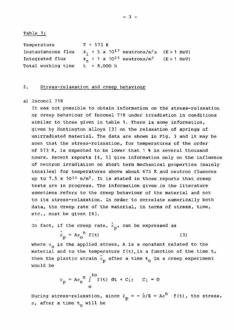
Table 1:
Temperature
Instantaneous flux
Integrated flux
Total working time
T oe 573 K
~. oe 5 x 10 17 neutrons/m 2 s1
~ oe 1 x 10 25 neutrons/m 2t
t oe 8.000 h
(E > 1 MeV)
(E> 1 MeV)
2. Stress-relaxation and creep behaviour
a) Inconel 718
It was not possible to obtain information on the stress-relaxation
or creep behaviour of Inconel 718 under irradiation in conditions
similar to those given in table 1. There is some information,I
given by Huntington alloys [3] on the relaxation of springs of
unirradiated material. The data are shown in Fig. 3 and it may be
seen that the stress-relaxation, for temperatures of the order
of 573 K, is expected to be lower that 1 % in several thousand
hours. Recent reports [4, 5] give information only on the influence
of neutron irradiation on short term mechanical properties (mainly
tensiles) for temperatures above about 673 K and neutron fluences
up to 7.5 x 10 26 n/m2 • It is stated in those reports that creep
tests are in progress. The information given in the literature
sometimes refers to the creep behaviour of the material and not
to its stress-relaxation. In order to correlate nurnerically both
data, the creep rate of the material, in terms of stress, time,
etc., must be given [6].
In fact, if the creep rate, E , can be expressed asp
E = Acr n f (t) (3)P 0
where cr o is the applied stress, A is a constant related to the
material and to the temperature f(t),is a function of the time t,
then the plastic strain E after a time t in a creep experimentp 0
would be
nE = AcrP 0
tof f(t) dt + Cuo
During stress-relaxation, since Ep = - ä/E = Acr n f(t), the stress,
cr, after a time twill beo

o
J
- 4 -
to= - A E f f(t) dt + C2 =
o
n- E E /0P 0
If n = 1, then
In (0/0 ) = - E E /0 and % = exp (- E Ep/OO)o p 0 0
so that the stress-relaxation ßOrel , after the time t o is
If n i: 1
= 1 - [1 + (n-1) EE /0 ]l/(n-1)p 0
(5)
It must be pointed out that "time-hardening" [7] was assumed,
which is a reasonable assumption for the in-pile behaviour.
In fact, the in-pile creep of some zirconium alloys [8] and stain-
less steels [9] seems to be described by an equation like (3).
When creep data are reported, the stress-relaxation will be
estimated by equations (4) and (5) for several values of n.
It should be reminded, however, that this will give only an idea
of the order of magnitude of the stress-relaxation involved
since, in addition, uniaxial conditions were assurned on deducing
these equations [10, 11].
As an example, from the reported creep properties of Inconel 718
[3], shown in Fig. 4:
Ep = 0,2 %; T = 866 K; t o = 1,000 h; = 703 MPa

- 5 -
the estimated stress-relaxation is
n ßO rel %
o 48
1 38
2 33.7
3 28.6.
These values are reasonable, when compared with those shown
in Fig. 3 at lower stresses. The value for n = 0 is an over
estimation.
b) Stainless Steels
b.1 SS 1.4980 (A-286)
No published data have been found for the in-pile creep and
stress-relaxation behaviour of this steel. Some results for the
tensile and creep properties, in unirradiated material, can be
obtained from the supplier [1~]. For exmnple, at 873 K with
00 = 360 MPa astrain of 0.2 % is obtained after 1,000 h.
No data are reported at lower temperatures.
With these values, the estimate stress-relaxation is
n ßO rel %
0 89
1 59
2 47
3 40
The stress-relaxation of this steel, for temperatures of
573 K and below, is expected to be slightly higher than that
of Inconel 718.
b.2 Other stainless steels
Only few published data were found for the stress-relaxation of
stainless steel, during irradiation.
J. W. Joseph, Jr. [13] reported some values of the stress-rela
xation behaviour of SS type 304, under neutron irradiatton.
Round specimens under compression were used and the irradiation
temperature was lower than 373 K. No stress-relaxation was ob
served in the unirradiated specimens tested at the same tempera
ture. The results are shown in Fig. 5 and, as discussed in the

- 6 -
paper, the data at the higher stresses are in error due to
the fact that the specimens were strained plastically.
In a later report by the same author and R. E. Schreiber [14]
some stress-relaxation data for the same material are reported,
but for measurements made in torsion with tubular specimens.
Essentially the same results were obtained as for compression
and they are shown in Fig. 6. The data shown in Fig. 5 are included
for a comparison.
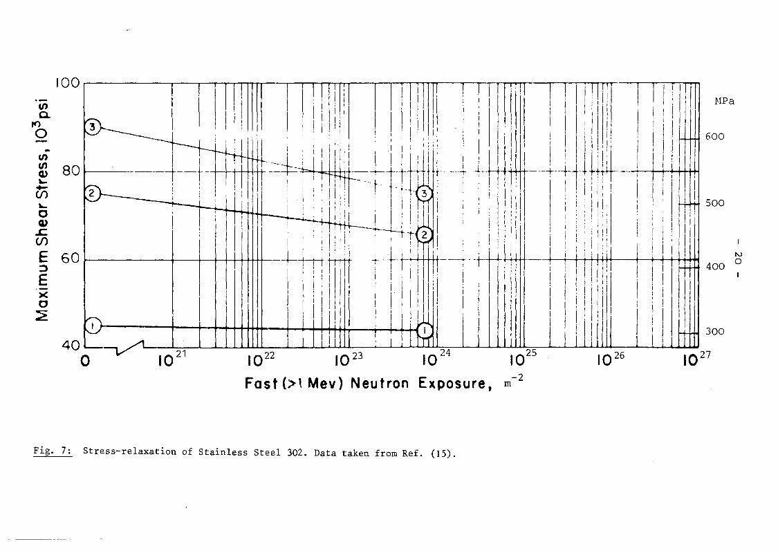
There are some reported results on the stress-relaxation of
SS 302 and 347. These data are given in ref. [15] and it was
not possible, up to now, to obtain the original papers. The
data on the 302 steel are shown in Fig. 7 and were obtained
at an irradiation temperature of 583 K under a flux > 10 16 n/m 2 s
(~ 1 MeV), in compressionsprings.
The results in SS 347 are shown in Fig. 8 and were obtained at an
irradiation temperature of 333 K, in bending, for a stress of
53 HPa.
There are sorne data on the creep behaviour of SS 302 measured
in springs, wi th a diame"ter of 9 mm and a wire diameter of 1.5 mm,
under a stress of 407 MPa. These results, reported in [15],
obtained at irradiation temperatures between 293 and 333 Kare
shown in Fig. 9. It is seen that the plastic strain is large,
exceding the elastic strain, so that the stress-relaxation
is expected to be high.
R. A. Wolfe and B. Z. Hyatt [16], reported some in-pile stress
relaxation data in Almar 362, a maranging stainless steel.
The measurements were done at two nominal temperatures 333 and
586 K, by using the bent beam technique. The results are shown
in Figs. 10 and 11. The authors did not give the initial stresses
but the radii of curvature. These stresses were calculated
from the radii taking E~190 GPa and the reported thickness.
The stress relaxation can be calculated from the figures with
the equation
~a = 1 - R IR.rel 0
It may be seen that the stress-relaxation varies between 40
and 60 %, according to the temperature and the initial stress.
The two type of specimens, A or B, differ in the initial cold-

- 7 -
working conditions and thermal treatments. The B specimens
were stressed to values above the yield stress.
D. Mosedale et al [9, 17] and G. W. Lewthwaite and K. J. Proc
tor [18], reported several data on the in-pile creep of SS
springs at stresses lower than 100 MPa. The data reported in
[18] were taken in two austenitic stainless steels, FV 548 and
ASI 316. The usual thermal treatments were given to the springs
with a diameter of 12.7 mm and a wire diameter of 1 mm. The
irradiation temperature was of the order of 373 K.
The results for the FV 548 springs are shown in Fig. 12.
These data correspond to the irradiation creep since the thermal
creep was subtracted out. The deflection, D, of the spring is
given in terms of the initial elastic deflection, D .eThe results for the ASI 316 springs are shown in Fig. 13. At
the stresses used, no thermal creep was observed in these
springs. The annealed spring crept transiently (~ 0.2 D ) andeconsiderably less than the cold-worked ones. An estimate of the
stress-relaxation can be made, form the values given in Figs.
12 and 13, by using equation (4) and the reported deflections
for the springs. The results are
a ßa rel %0
43.3 58
26.6 61 Fig. 12
41.8 41 Fig. 13
For the data reported in references [9] and [17] it was found
that springs made from seven austenitic stainless steels crept
far more in reactor, at temperatures of the order of 553 K,
than in the laboratory at the same temperatures. The specimens
were irradiated at a flux of the order of 3 x 10 19 n/m2 s
(> o. 1 MeV).
There are several addi tional ~su1fs reported in t.I1es~papers and they
will not be detailed. As an example, Fig. 14, taken from
reference [17], shows a comparison between the irradiation in
duced creep in springs of ASI 316 and the thermal creep at a
much higher temperature. It is seen that the irradiation induced
creep is very high.

- 8 -
A stress-relaxation of the order of 30 % is obtained with
equation (4) from the data of Fig. 14, in the irradiated specimen
and after 4000 h.
Finally, K. D. Closs et al [19], reported some data on the in
pile creep of SS 1.4981, cold-worked 15 %. The measurements were
taken in rods of 3 mm in diameter and 50 mm long.
The change in length as a function of the irradiation time
is shown in Fig. 15 and it is independent of temperature for
temperatures between 623 and 723 K. Using equation (4), with
E = 180 GPa [12], a stress-relaxation of the order of 90 %
is obtained, with the reported dimensions.
c) Zirconium alloys
Several data for the in-pile creep and stress-relaxation of
zirconium alloys have been published in the literature [20-27]
and only the most representative will be shown.
Fig. 16 (a) to (e), from reference [20], shows some results on
the stress-relaxation of zircaloy-4 with different thermo-mechani
cal treatments and in Zr + 2.5 wt % Nb + 0.5 wt % Cu. It is seen
that the irradiation increases the stress-relaxation at both tem
peratures. It must be pointed out that the stress-relaxation data
in zirconium alloys, given in Figs. 16 to 19, were measured by
the bent beam technique. Fig. 17, taken from reference [23],
shows the stress-relaxation behaviour of zircaloy-2 specimens
with different initial conditions, at various stresses. The
specimens were prepared from pressure tubes in hoop (transverse)
and longitudinal directions. The longitudinal specimens were
cutted with the neutral axis either in the tangential (T) or
in the radial (R) direction. These data were taken at temperatures
of the order of 573 K and at a fast neutron flux (E > 1 MeV) of
2 x 10 17 n/m2 s. As for the data shown in Fig. 16, the in-pile
stress-relaxation is higher than that observed in the unirradia
ted material. Similarly, Fig. 18, taken from reference [22],
and Fig. 19, taken from reference [23], show the stress-relaxation
behaviour of Zr-2.5 wt % Nb at similar temperatures and neutron
exposures.

- 9 -
Discussion and conclusions
Under the working conditions given in table 1, the Zr-2.5wt%
Nb alloy shows the lowest stress-relaxations when compared with
the rest of the commercial zirconium alloys (no data were found
for Zr-1 wt% Nb). In fact, from Figs. 18 and 19(c) it is seen
that this alloy relaxes 50 % or less if the appropriate thermo
mechanical treatments are used. These values are valid for stres
ses of the order of 200 MPa since the creep rate and consequent
ly the stress-relaxation is expected to increase very rapidly at
stresses above about 300 MPa [26].
It is clear that a stress-relaxation of the order of 50 % is too
high when compared with the values expected, from out of pile mea
surements, for Inconel 718 (less than 1 %), Fig. 3, or SS 1.4980.
The question is: Are the out of pile data representative of the
in-pile behaviour? Unfortunately, as pointed out before, it was
not possible to obtain information on the in-pile creep or stress
relaxation of these materials. However, if the stress-relaxation
of Inconel 718 and SS 1.4980 is affected by irradiation in a way
similar to the reported steels, shown in Figs. 5 to 15, then their
in-pile stress-relaxation is expected to become of the same order
of magnitude as that found in Zr-2.5 wt% Nb.
It is evident that an important experiment would be to measure the
elastic behaviour of the structural elements after servicing, i.e.,
when the fuel elements are changed. If the stress-relaxation is
found to be of a few 10%, then these elements can be made of Zr-2.5
wt% Nb it the working stresses are of the order of 150 MPa. No cor
rosion problems are expected since this zirconium alloy shows ex
cellent corrosion behaviour.
Finally, more experimental work is needed on the in-pile stress
relaxation of zirconium alloys, stainless steels and Inconel 718,
since the out of pile data are not representative, specially at low
temperatures. For example, the irradiation induced creep and stress
relaxation in stainless steels seem to decrease slightly with in
creasing temperatures [9,17,18]. This is an interesting proble~ too,

- 10 -
from the point of view of an understanding of the fundamental
mechanisms of irradiation damage.
Acknowledgements
I wish to express mey thanks to Prof. L. Fernandez and Lic. R.
Giadanes, of CNEA, and to Dr. K. Herschbach, Ing.M. Schirra and
Dipl.-Ing. C. Wassilew, of KFK, for their contribution to this
work.
This work was performed within the Special Intergovernamental
Agreement on the Scientific and Technological Cooperation be
tween Argentina and the Federal Republic of Germany.

- 11 -
References
[1 ] S. Timoshenko;
"Strength of Materials" (Part I). Van Nostrand Reinhold
Co. (1958), p. 290.
[2] F.V. Warnock and P.P. Benham;
"Mechanics of Solids and Strength of Materials". Pitrnan
(London), (1965), p. 161.
[3] Huntington Alloys;
"Inconel alloy 718 11• The International Nickel Co. (1973).
[4] Semi-Annual Progress Report;
"Irradiation Effects on Reactor Structural Materials". Re
port HEDL-TME 75-95; UC-79b (1975).
[5] J.M. Steichen and A.L. Ward;
IIEffect of strain rate on the tensile properties of irradi
ated Inconel 718 11• Report HEDL-TME 76-14; UC-79h, p (1976)
[6] J.B. Conway, R.H. Stentz and J.T. Berling;
IIFatigue, Tensile and Relaxation behaviour of Stainless Steels ll,.
USAEC, Technical Information Center (1975).
[7] I. Finnie and W.R. Heller;
IICreep of Engineering Materials ll• McGraw-Hill, N.Y. (1959).
[8] D.E. Fraser;
IIStress-relaxation testing of small bent bearns ll• Report AECL
3782 (1971).
[9] D. Mosedale, ,G. W. Lewthwai te and 1. Ramsay;
"Further creep experiments in the Dounreay fast reactor". Proc.

- 11 a -
Conf. on Irradiation Embrittlement and creep in fuel clad
ding and core components. BNS, London (1972).
[ 10] F. Povolo;
"The determination of creep constants from stress-relaxation
in bending and torsion". J. Nucl. Mater. 68 (1977) 308.
[11] F. Povolo and E.H. Toscano;
"On stress-relaxation in bending. An example for Zry-4".
J. Nucl. Mater., to be published.
[12] Röchling'sche Eisen- und Stahlwerke GmbH, Völklingen (Saar)
"Handbuch für hochwannfeste Stähle und Legierungen". p. 49
[13] J.Walter Joseph, Jr;
"Stress-relaxation in stainless steel during irradiation"
AEC Report DP-369 (1959).
[14] J.W. Joseph,Jr; and R.E. Schreiber;
"Relaxation of torsional stresses in stainless steel during
irradiation". AEC Report DP-669 (1962).
[15J R.E. Schreiber;
"Mechanical properties of irradiated stainless steels. A com
pilation of the data from the literature". AEC Report DP-579
(1961).
[16] R.A. Wolfe and B.Z. Hyatt;
"Viscoelastic analysis of in-pile stress-relaxation", J.Nucl.
Mater.45 (1972) 181.
[17] G.W. Lewthwaite and K.J. Proctor;
"Irradiation-creep in a materials testing reactor". J. Nucl.
Mater. 46 (.1973) 9.

- 12 -
[18] D. Mosedale and G.W. Lewthwaitei
"Irradiation creep in some austenitic stainless steels
Nimonic PE 16 alloy and Nickel". Proc. Conf. on Creep
strength in steel and high temperature alloys. ISI, Shef
field (1972).
[19] K.D. Closs, K. Herschbach and W. Schneideri
"Experimentelle Untersuchungen zum bestrahlungsinduzierten
Kriechen an stabilisierten Stählen". Proc. Conf. on Irradia
tion behaviour of fuel cladding and core component materials.
Karlsruhe (1974).
[20] P.H. Kreyns and M.W. Burkarti
"Radiation-enhanced relaxation in Zircaloy-4 and Zr-2.5 wt%
Cu alloys". J.Nucl. Mater. 26 (1968)87.
[21] E.F. Ibrahim, E.G. Price and A.G. Wysiekierskii
"Creep and'stress-rupture of high strength zirconium alloys",
Can. Metallurg. Quarterly 11 (1972) 273.
[22] P.A. Ross-Ross, V. Fidleris and D.E. Fraser;
"Anisotropic creep behaviour of zirconium alloys in a fast
neutron flux" , Ibid. p. 101.
[23] D.E. Fraser, P.A. Ross-Ross and A.R. CauseYi
"The relation between stress-relaxation and creep for some
zirconium alloys during neutron irradiation". J. Nucl. Mater.
46 (1973) 281.
[24] A.R. CauseYi'
"In-reactor stress-relaxation of zirconium alloys".ASTM Sympo
sium on Zirconium in Nuclear Applications. Portland, Oregon
(1973). ASTM STP 551.

- 13 -
[25] A.R. CauseYi
"In-reactor creep of Zircaloy-2, Zircaloy-4 and Zr-1.15
wt% Cr-O. 1 wt% Fe at 568K derived from their stress-re
laxation behaviour". J.Nucl. Mater. 54 (1974) 64.
[26] C.E. Coleman, A.R. Causey and V. FidleriSi
"Uniaxial in-reactor creep of Zirconium-2.5 wt% Niobium
at 570K". J. Nucl. Mater. 60(1976) 185.
[27] A.R. CauseYi
"Thermally induced strain recovery in irradiated and un
irradiated zirconium alloys stress-relaxation specimens".
J. Nucl. Mater. 61 (1976) 71.

- 14 -
Fig. 1

- 15 -
\ /\ /
\ /Ro/\ /
\V
Fig. 2

- 16 -
8r---__.,,....--~--__r_--~--.,..,...--_r___-......,r__-__.,--__r--.......
811 K/421 MPa1
2
7
6866 K/491 MPa
5
?P-o
c0 4.....cuxcu(1)
K/4210::: 3 866 MPa
1000800600400200
Ol&.-_---L__~__..L....__ _...I.__..........__.l..__ ____L__..........__.L__ ___J
oTime, hr
Fig. 3: Relaxation of helical coil springs made from 3.76 mm - diametercold-drawn Nr. 1 Temper wire. (Springs annealed 1255 K/lh andaged 991 K/8h. F.C. to 894 K, hold at 894 K for total aging timeof 18 h). Data taken from Ref. (3).

- 17 -
800
700
600
F:C 500~
lI'llI'lQ)
::; 400Cf)
300
200
850
0.5% PlasticStrain
900
Temperature, K
Stress to Producein 1000 h~
1.0% PlasticStrain
950 1000
Fig. 4: Creep-rupture properties (1000 h) of hot-rolled, 15.88 mm diameter bar (1255 K/lh, W.Q. and aged 991 K/8h, F.C. to 894K, hold at 894 K for total aging time of 18 h). Data taken fromRef. (3).

250
Notas:
"/o
l'dP-!::::
VIVI~~-V')
~
IIIc:::~
I-uVIC
W
200
150
100
50
1. Temperature of sp~cimens during irradiationwas less than 373 K
2. Fast neutrons Include all those with energiesgreater than O. 1 Mev
3. Numbers above each data point are total numberof specimens for which data were averaged toobJain po int. 4
2,
-"co
oo 2 X 10
24
4
4 X 10 24 6 X 1024
2
8 X 1024
10 x 1024
Exposure I fast neutrons / rn2
Fig. 5: Stress relaxation in type 304 Stainless Steel during irradiation. Data taken from Ref. (13).

- 19 -
HPa
- 50
- 100
- 150
--~~I'-.. TorsionI ...........~--I--+----+--+---4
5
1\
\;~~20 --- ----~--J- f------f-----~-_+---~-__l
\>-~. I
i I~i ~, "~.iO"~I ,I . ~! ~ j -1-- ~~orsion ~;>--
I\,:~ I~~ i
Tension "ß,. i Torsionc----F
1Prl
l
-+=;:..,:-~4==rr---jI 1 I
Tension
i~
iN: I ~'5 f--l---I----+-~t>--+-----1---r--"'""'t_~r_r__-___t_-____1
I I
I Dat~ spreods show~ represent one standard deviationO!-.-.JIL.-~_---l_~----J...---7------l.-_--:;---'---;'n----J0o 2 4 6 8 10
Fast Neutron Exposure, 1024 n/m2,per unit
Fig. 6: Comparison of shear stress-relaxations in tensileand torsional specimens of 304 Stainless Steel.Data taken from Ref. (14).
MPa
300
500
600
10 27
-2m
I0 22 I0 23 I0 24
Fast (>' Mev) Neutron Exposure,
1021
40~--,
o
100 11 I I I, i ifl"!'1llTTW~ k'll'i'll\ '11!'iii I/I!I!,IIIIII:I'
'0 3 I· 11, I I:! i Ili'I I!, 1IIIili ! ,I;! I I I I i 11 I
I 'I'''' " ' "" I !' 111' I I ! I I '.. ! r 'li 11 i, l:i;::1 'I'; 01 ~i:! 11
1
'1 I i II:i','!Cf) I H+ i~'i",'II! I DII' IJII 'l'+M'Cf) . --- !; I , I I i i 'I 1 1
Q) 80 -------t--- I
.• --, ~ i, i '--+-+- - t r-,- ----1" -,-H ----t--+i-+,," --- j I I "I tH~ , ! I I 1I1 : i I : - -. t - i' I I ! I :! 11 I I I I I i ! ;+- , " I" , ! I! 'li .' --{ i 1 : i, I I
'!! I
(f) : :,: I ! 11 • i :, I, i i I I 1- 3 I !'! I I I 'I I' i , I:' ', i,' I I 1 , i li': 'I' I . I' , " j : I' I
O~ : ' I !+4+ti-'!:;I i '11 m"! 'I i : il'II'1 I i : ;,1, :" . " I" I I!, , , , I '. " ,I ", I I ' . 1 I I I I I I
CI) I I ,I I, I' I I :: I 'I i 11 'I i : i " i·.c. i I i '1
1
:. : i , ' , i I --~----t t.' 2 'i : I I' i I' i i' i I [
(f) ! I, i ! I: . : li::; ::,;'! : i ! I I' II! 1
1
:! i liE 60 I tmt' .\, " " +t H-H'i I ,;, "lliH' IV~-----+--~+-+-++++++---r-!-!i-+-+r' ;--'-f --t- . j I I I 1 I 0=' 1 I ! I I 11 I! I i i I i. ': I I , ,I' I I' I ; 400E ' I I I I i" I, I I' I
)( ! i : I1I ' ". 11 i II I I~ I 111 i i [li: [lil'!1 1111I1 i
Fig. 7: Stress-relaxation of Stainless Steel 302. Data taken from Ref. (15).

IV.....
MPa
50
45
10 27102610251022
10 23 1024
Fast(>lMev) Neutron Exposure, rn-2
10 21
8
I
71 ' 55
II
I6-'~,o
~
""cnCl>L--([)L-o 0_-Q) cn
.s::. ~(f)ff1
EO:JE-)(o2
Fig. 8: Stress-relaxation of Stainless Steel 347. Data taken from Ref. (15).

IVIV
I i I Ii I 11
I 11
I I
'4Ij
l i II I I
I I111
r"'0oolIo...
~ i! ,llli'll I:. ii1.iil ! '+ 1II
1
!!! IIII1 .:J 1 'i '#WIIII I I I I I !I,j ! + I;'I I,! I _~,c 4 - - ·-.---t -_. i 1" ! \--- - ---t,-. -
~ es .1 I ,I '-I! i:! 111! I I I! I I i il III'IIII!U...... I I: ' 1
'!II '. :1 ': I
1 I I \,~ 2 ' -+ i I I :
u I.:! !I 'I' ','i I- I I' 'Itf) I 1 i
o 111'1 11II
: 1 I 1 1
1i I 1'1 1
0' I I _l.~"""""""'~:-:--..<...-..oL.1~~&.:-=-"'-~-'--4.L.~--..L-""""""~"'"10
2110
221023 1024 10 27
Fast (>1 Mev) Neutron Exposure. m-2
Fig. 9: Creep of Stainless Steel 302. Data taken from Ref. (15).

- 23 -
---
1.0 .-------,~--~----.----.......---.__---r_--___,0.9
0.8
0.7
a: 0.6.....
0a:
LU 0.5a:::::>....:;a:::::>0 0.4u..0(/)
::::>0CI:a:
0.3SPECIMEN TYPE cr (MPa)-- -0
0 03 A 3830 018 A 2260 025 B 1100
6. 026 B 850
0.20 I 2 3
FLUENCE ( 1025 n/m2 • E> I MeV)
Fig. 10: In-pile stress-relaxation of Almar-362 at a nominaltemperature of 333 K. Data taken from Ref. (16).

- 24 -
I. 0 ~----,r---""I----r---...-----.,r------..,..---_
0.9
0.8
0.7
-0:: 0.6......o
0::
LU
~ 0.5.....~a:::::::>ul.L OAo(f)
::::>a<t0::
(NOMINAL TEMPERATURE-586 K)
0.3
o6.oo
SPECIMEN
08015021022
TY PE 00
(MPa)
A 396A 230
B 772B 660
764 5E > I MeV)
2 3FLUENCE (10 25 n/m2
O. 2 '-- ~ ___L. ----"'I--- ...L_.. ~ __L ~
o
Fig. 11: High ternperature in -pile relaxation of Almar-362. Data taken fromRef. (16).

I ·0
'8
•0
" '60--0
•·4 to
- 25 -
2
(m-2 )Flucncc (E >1 HeV)
Fig. 12: Creep of cold-worked FV 548 springs; e 43.3 MPa,o 26.6 MPa.Data taken from Ref. (18).

- 26 -
+·8
0 + 0+ 0 -
+ ~0 0 o Co I d-o X X·6 Workcd
~
u J-X x0 ·4---0
<:x/ • •
2 - -- -. - --e-e- Anncalcd
•QL-... L.- ..a..- ........_--..._
Q 2 3 )( 1,024
Flucncc
Fig. 13: Creep af 316 springs; 9 41.8 MPa and, fram first experiment,a 39.5 MPa, + 38.2 MPa, x 62.5 MPa. Data taken fram Ref. (18).

r'..
•6
I I --r--
• 395/~ (~). 22·~ MPa , 538K ~ T .c.. 553K-6 -I-I
DISPLACEMENTS PIK>DUCTION IV ·4~ °10 ATOt.4 5
- _-e --6.0 - 30 % erel - -+---------
r-J-...J
-
THERMAL CItEEP AT ·773K
+,33 MPa , X, 27·5 MPa
---+-+-~-+-+ +- + +-+-+---......-+~-+-+~,+ - ~/+_X_X_X_X_X_X~."'X_X X-X x-x-'-x I X x-
)t"'x
+I
+-
4
z
o.0zCIE~
on
o I I I I I Io 1·0 Z·O 3-0 4·0
TIME (103h)
Fig. 14: Comparison of irradiation creep at 538K-553K and thermal creep at 773K of cold-workedM316 (Batch 2) springs. Data taken from Ref. (17).

- 28 -
180--------------...------------...
160 r--n 3K----++----h638K-~+~I---623K---""'+
of
.--1. 4981. (15% c. w. )
G=150 HPa
~ (E>O.1MeVl=58)(1018 n/m2
5.
•
140E::1. 120 -
.• ~·_·;;:ctoron
~:...
<I 100 • ••• •.. .. ......r::: ~.
~ 80 ä ....~ •
~ ~ .60
~ 40r.ncoQ)
~ 20uI=:
"ri
O---...,....--r"--..,.-------,---+-,...-ooor----+-------~2000 2500 3000 3500 4000
time I h ]
Fig. 15: In-pile creep of Stainless Steel 1.4981. Data takenfrom Re f. (1 9) •

14cf> = 2 4 X IOnv (> 1 HeV)~ ~----.....f..-r
IV\D
3000
(a)
__--0
--..l.- I ,
2000
IN - PIL E 5 83 K , 66 • 2 HPa
IN-PILE 333 K, 53.8 HPa
OUT - OF-PI L E 583 K, 75.6 MPa
OUT-OF-PILE 333 K, 66.2 HPa
oo
••
1000
~• .1
1 I
~-----. -ci]__--~=-----lLJ:r--------___ ., 1-
100
90
80
z 700-~
<X 60x<X--.JW 50er~zw 40 .-uerwCl. 30
20
10II
0"-0
TIME, h
Fig. 16a: Relaxation of alpha-annealed Zircaloy-4. Data taken from Ref. [20].

.... .-----
wo
3000
(b)
2000
o I N - PI L E 583 K, 106 HPa
o IN- PILE 333 K, 103.5 MPa
• OUT - OF - PI LE 553 K, 69 MPa
14.• ::24XIQ nv
1000
100
90 .-
80
z 70 --0-~
<t 60x<t-.JW 50Cl:
~
Z.W 40uCl:wCL 30
20
10
00
TI ME. h
Fig. 16b: Relaxation of beta-quenched Zircaloy-4. Data taken fram Ref. [20].

o IN-PILE 583 K, 111.8 MPa
o IN-PILE 333 K, 102.1 MPa
'" -e e OUT -OF _PILE 583 K, 118 MPa
10,{-" • OUT -OF- PILE 333 K, 142.1 MPa
oL-- i i i I I I I I I I I I I I Io 1000 2000 3000
20
100I I I I I I I I I I -I I I
90(e)_.
-
Ir/J : 2.4 X 10'4 nv
80 ------z 70 --0-~
<t:60x
<t:....JWa:: 50~
z40 I Iw ~
ua:::
I w
w
.....
a.. 30
TIME, h
Fig. 16c: Relaxation of 15% cold-worked Zircaloy':""4. Data taken fram Ref. [20].

100
90
80
z700-....
<t)( 60 ---<t.....JWer 50I-z.w 40uerwa.. 30
2LJ
10
I ' ,i 1 -T --,
Cd)
o IN-PILE 583 K, 103.5 MPa
o IN- PILE 333 K, 107.6 MPa
.OUT-OF-PILE 583 K, 107.6 HPa
• 0 UT - OF - PI LE 333 K, 127 MPa
ep 14 I w= 24 X 10 nv N
.-----.
II I I
I I I i
0'-:- I i I 1000oTI ME. h
2000 3000
Fig. 16d: Relaxation of 79% cold-worked Zircaloy-4. Data taken from Ref. [20].

100
90
80
z0 70--~
<tX 60<t....JUJa:~
zwua:UJa.. 30
20
10
c •,o I N - PILE 583 K, 237. 4 HP a
o I N- PILE 333 K, 265 !''1Pa
• OUT- OF- PI LE 583 K, 241,5 l''1Pa
• OUT- OF· PI LE 333 K, 241. 5 ~Pa
ep: 2.4 X 10 14 nv
( e)
ww
0"1 I I ! I I ! ; \ I I I i :
o 1000 2000 3000TIME, h
Fig. 16e: Relaxation of Zr+2.5 wt% Nb + 0.5 wt% Cu. Data taken from Ref. (20).

- 34 -
1 00 r-------------------------"""------
bO,bCl
~
erc::V'lV)~J
c::~
V'l
ClLU><<:---JLUc-:-.,..--:::> O. 10
-- ----------~
oo
S.R. ZIRSALOY-2
o LONGITüDINAL
6 HOOP
-- - AUTOCLAVED HOOP
(Jo 172 MPa
o 2 3 4
TIME x 10- 3 h
5 6 7 8
Fig. 17a: Unrelaxed stress ratio as a function of time for Zircaloy-2 at566K, stress-relieved. The autoclace tests were performed at573 K. Data taken from Ref. (23).

- 35 -
1. 00 ~---------------------------------,
bO.......b
06
I- 6 0c::ea::V)V)
UJa::
ZIRCALOY-2I- S.RV)
0 0.10 0-0UJ><c::e.:..J
103 MPaUJ 0a::Z:::> ~ 172 MPa
o 3 4 5 6 7 8
TIME x 10':"3 h
Fig. 17b: Unrelaxed stress ratio as a function of time for Zircaloy-2 at566 K, stress-relieved. The autoclave tests were performed qt573 K. Data taken from Ref. (23).

- 36 -
1 08,.....--------------------------,
bO.......b
0
I-<C0:
l/)V)
LU0:l-V)
0LU><<C-ILU0:
0.10z::>
(Jo
c.w. ZIRCALOY·~_
o T
6 R
172 MPao
o 2 3
TIME
4
x 10-3 h
6 7 8
Fig. 17c: Unrelaxed stress ratio as a function of time for Zircaloy-2 at566 K, cold-worked. The autoclave tests were performed at 573 K.Data taken from Ref. (23).

- 37 -
1 00 r------------------------~...,
00"-b
Cl
--.::::::l.:
(/)
.. '1LICA::
--(/)
ClLU><C(
-JUJ 0 10a:::z::J
c W ZIRCALOY-2..- ---
Uo
r"" 103 MPa.-.J
t::. 172 MPa
+ 241 MPa
o 2 3 4
TIME x 10- 3 h
5 6 7 B
Fig. 17d: Unrelaxed stress ratio as a function of time for Zircaloy-2 at566 K, cold-worked. The autoclave tests were performed at 573 K.Data taken frome Ref. (23).

- 38 -
1.00 r------
--------
c.w ZIRCALOY-2
0 LONGITUDINAL
6 HOOP
_.- AUTOCLAVED HOOP
0"0 = 172 MPa0
bO.....b
0
I-c:x:c:::V)V)
UJc:::l-V)
CJUJ><c:x:--IUJc:::
0.10z::::J
L-_~ L --'-__-----1-__.....J
o 2 3 4
TIME x 10- 3 h
5 13 7 B
Fig. ] 7e: Unrelaxed stress ratio as a function of time for Zircaloy-2 at566 K, cold-worked. The autoclave tests were performed at 573 K.Data taken from Ref. (23).
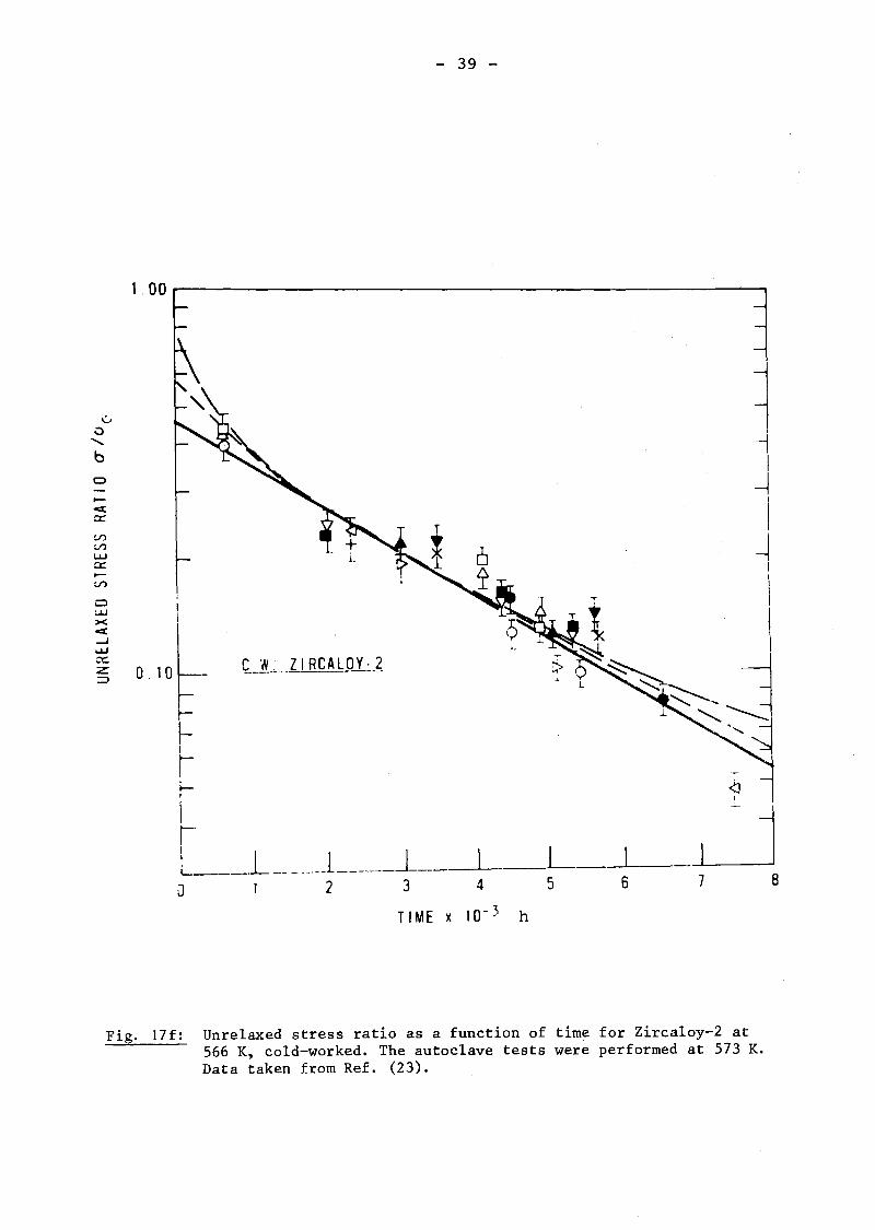
- 39 -
1" 00 r--------------------------....-..,
L
c.~_~.~"""z I RCAL'p..1:..2.
<JI
7 8-~
I
o IO~-r-rr~
II"L. .L ._.l J ~---L-.J-J 2 3 4 5 6
o
TIME x 10- 3 h
Fig. 17f: Unrelaxed stress ratio as a function of time for Zircaloy-2 at566 K, cold-worked. The autoclave tests were performed at 573 K.Data taken from Ref. (23).

ow><«......wZ .2,:)
..gb-I
ZoI
U-<0::....V)V)
w0::lV)
- 40 -
1.0.9
.8
.7
.6
.5
.4[J
.3
----------------
[J
[J
B[J-AXIAl DIRECTION 2xl01'ln/cm2 (>lMeV)0-TRANSVERSE DIRECT·ION.2x1013
" 'cm2s(> lMeV)--- -TRANSVERSE DIRECTION.OUT CF REACTOR
.1o 2 3 4 5
TIME -HOURS X 10-1
6 7
Fig. 18: Results from stress-relaxation tests with specimensfrom heat-treated Zr-2.5 wt% Nb tubes. Tests performedat' 558 K and at a nominal initial stress of the orderof 150 MPa. Data taken from Ref. (22).

- 41 -
1 00 ,----------------------~--~----~__,
bO......b
c::J
~
e:ta:::
V)V)
UJa:::~
V)
cUJ><e:t-JUJ O. 10a:::z::::>
H.T. Zr-2.5 wt % Nb(Jo
0 103 MPa
~ 172 MPa
+ 241 MPa
o 2 3 4 5 6 7 B
TIME x 10-3h
Fig. 19a: Unrelaxed stress ratio as a function of time for Zr-2.5 wt%Nb. Inreactor tests at 566 K and autoclave tests at 573 K,heat-treated. Data taken from Ref. (23).

- 42 -
:.00
.00.......b
0
.....ca:V)
rV)
LUa: H T.....V)
c 0LU>CC 6...JLU O. 10a:z --:=l
Zr-2 5"d:. N:
LONGITUDINAL
HOOP
AUTOCLAVED HOOP
o
ClO
= 172 HPa
2 3 4 5 6~
/ a
TIME x 10-3 \HOURS)
Fig. 19b: Unrelaxed stress ratio as a function of time for Zr-2.5 wt% Nb.Inreactor tests at 566 K and autoclave tests at 573 K, heattreated. Data taken from Ref. (23).

- 43 -
1.00 r-----------------------------,
bO.......
bC)
.....<[
0:::
V)
V)
~
a:V')
Clu.J><<[
0 10-Ju.J0:::Z~
c.w Zr -·2 . 5 ~t N!l---_._-------
(jo
0 103 MPa
L). 172 MPa
+ 241 MPa
o 2 3 4 5 6 7 B
TIM E x 10-- 3 h
Fig. 19c: Unrelaxed stress ratio as a function of time for Zr-2.5 wt% Nb.Inreactor tests at 566 K andautoclave tests at 573 K, ·cold-worked. Data taken from Ref. (23).

- 44 -
1.00 r--------------------------.
bO"b0
~
«0:::
V)
V)
LU0:::~V)
c:lLU><«.....JLU0:::
0.10:z::l
C. W Zr - 2 . 5w t % NIl
o LONG ITUD INAL
6 HOOP
- - - AUTOCLAVED HOOP
a: :-. 172 MPao
o
o
oo
o 2 3 4 5 6 7 8
TIME x 10- 3 h
Fig. 19d: Unrelaxed stress ratio as a function of time for Zr-2.5 wt% Nb.Inreactor tests at 566 K and autoclave tests at 573 K~ cold-worked. Data taken fromRef. (23).