Embed Size (px)
Citation preview
On Design Methods for Mechatronics Servo Motor and Gearhead
TRITA – MMK 2005:02 ISSN 1400-1179
ISRN/KTH/MMK/R-05/02-SE
Licentiate thesis Department of Machine Design Royal Institute of Technology SE-100 44 Stockholm
FREDRIK ROOS

TRITA – MMK 2005:02 ISSN 1400-1179 ISRN/KTH/MMK/R-05/02-SE
On Design Methods for Mechatronics - Servomotor and Gearhead
Fredrik Roos
Licentiate thesis
Academic thesis, which with the approval of Kungliga Tekniska Högskolan, will be presented for public review in fulfilment of the requirements for a Licentiate of Engineering in Machine Design. The public review is held at Kungliga Tekniska Högskolan, Brinellvägen 83 in room B442 at 10.00 am on the 1st of February 2005.
III
TRITA - MMK 2005:02 ISSN 1400 -1179 ISRN/KTH/MMK/R-05/02-SE
Mechatronics Lab Department of Machine Design Royal Institute of Technlogy S-100 44 Stockholm SWEDEN
Document type Licentiate Thesis
Date 2004-12-23
Supervisors Jan Wikander, Hans Johansson
Author Fredrik Roos ([email protected])
Sponsors: Gröna Bilen: Volvo AB, Scania CV AB, Volvo Cars, SAAB Automobile
Title On Design Methods for Mechatronics - Servo motor and Gearhead
Abstract The number of electric powered sub-systems in road-vehicles is increasing fast. This development is primarily driven by the new and improved functionality that can be implemented with electro-mechanical sub-systems, but it is also necessary for the transition to electric and hybrid-electric drive trains. An electromechanical sub-system can be implemented as a physically integrated mechatronic module: controller, power electronics, electric motor, transmission and sensors, all integrated into one component. A mechatronic module, spans, as all mechatronic systems, over several closely coupled engineering disciplines: mechanics, electronics, electro-mechanics, control theory and computer science. In order to design and optimize a mechatronic system it is therefore desirable to design the system within all domains concurrently. Optimizing each domain or component separately will not result in the optimal system design. Furthermore the very large production volumes of automotive sub-systems increase the freedom in the mechatronics design process. Instead of being limited to the selection from off-the shelf components, application specific components may be designed. The research presented in this thesis aims at development of an integrated design and optimization methodology for mechatronic modules. The target of the methodology is the conceptual design phase, when the number of design parameters is relatively small. So far, the focus has been on design methods for the electric motor and gearhead, two of the most important components in an actuation module. The thesis presents two methods for design and optimization of motor and gearhead in mechatronic applications. One discrete method, intended for the selection of off-the-shelf components, and one method mainly intended for high volume applications where new application specific components may be designed. Both methods can handle any type of load combination, which is important in mechatronic systems, where the load seldom can be classified as pure inertial or constant speed. Furthermore, design models relating spur gear weight, size and inertia to output torque and gear ratio are presented. It is shown that a gearhead has significantly lower inertia and weight than a motor. The results indicate that it almost always is favorable from a weight and size perspective to use a gearhead. A direct drive configuration may only be lighter for very high speed applications. The main contribution of this thesis is however the motor/gear ratio sizing methods that can be applied to any electromechanical actuation system that requires rotational motion.
Keywords Mechatronics Design Methodology, Servo Systems, Electric Motors, Gears, Auxiliary Systems
Language English


V
Acknowledgements The research presented in this thesis is a result of the Auxiliary Systems part of the ‘Gröna Bilen’ / FCHEV program, jointly funded by the Swedish Government, Scania CV AB, Volvo AB, Volvo Cars and SAAB Automobile. The work has been conducted at the Mechatronics Lab at the Department of Machine Design at KTH in Stockholm, Sweden.
I would like to express my gratitude to all people that have been involved in the project, especially my supervisor, Professor Jan Wikander, first of all for hiring me, but also for all help with the research and editing of the papers. My co-supervisor, associate Professor Hans Johansson has been a very good help in understanding electrical motor drives. I would also like to thank Christer Spiegelberg at the Machine Elements division for working with the gear sizing models with me.
Further on I would like to thank my roommates Henrik Flemmer and Magnus Eriksson and all the other colleagues at the mechatronics lab for providing support in the daily work and a pleasant working atmosphere. Last but not least I would like to thank my family and friends. Stockholm, December 2004 Fredrik Roos

VII
List of appended publications Paper A: Fredrik Roos and Jan Wikander, Towards a design and optimization methodology for automotive mechatronics, 30th FISITA World Automotive Congress, Barcelona, May 2004 Fredrik Roos wrote the paper, many of the ideas were provided by Jan Wikander. Paper B: Fredrik Roos, Hans Johansson, Jan Wikander, Optimal Design of Motor and Gear ratio in Mechatronic Systems, 3’rd IFAC Symposium on Mechatronic Systems, Sydney, September 2004 Fredrik Roos did all writing and calculations, many of the ideas were provided by Hans Johansson. Report C: Fredrik Roos and Christer Spiegelberg, Relations between size and gear ratio in spur and planetary gear trains, Technical report, TRITA-MMK 2005:01, ISSN 1400-1179, ISRN/KTH/MMK/R-05/01-SE, November 2004 The work was initiated by Fredrik Roos. Christer Spiegelberg provided many ideas. The calculations, writing and implementation were done in close collaboration between the two authors. Paper D: Fredrik Roos, Hans Johansson, Jan Wikander, Optimal Selection of motor and gearhead in mechatronic applications, Submitted to: Mechatronics – The Science of Intelligent Machines – An International Journal, December 2004. All calculations, implementation and writing were done by Fredrik Roos. Hans Johansson contributed with his knowledge in electric drives. Hans Johansson and especially Jan Wikander have done a great work in editing the papers.

VIII
Other publications Fredrik Roos and Jan Wikander, Mechatronics Design and Optimisation Methodology – A problem formulation focused on automotive mechatronic modules, Mekatronikmöte, Göteborg, August 2003.
IX
Contents
1 INTRODUCTION......................................................................................................1 1.1 VEHICLE AUXILIARY SYSTEMS .............................................................................1 1.2 MECHATRONICS DESIGN METHODOLOGY .............................................................2 1.3 GOAL ....................................................................................................................3 1.4 RESEARCH APPROACH ...........................................................................................3 1.5 FOCUS: SERVO MOTOR AND GEARHEAD ................................................................4
2 SUMMARY OF APPENDED PAPERS...................................................................7
Paper A: Towards a design and optimization methodology for automotive mechatronics ................................................................................................................7 Paper B: Optimal design of motor and gear ratio in mechatronic systems.................7 Report C: Relations between size and gear ratio in spur and planetary gear trains ..7 Paper D: Optimal selection of motor and gearhead in mechatronic applications......8
3 CONCLUSIONS.........................................................................................................9
4 DISCUSSION AND FUTURE RESEARCH .........................................................10 4.1 LOSS MODELING AND HEAT .................................................................................10 4.2 LOCAL ENERGY STORAGE / SUPER CAPACITORS...................................................10 4.3 VARIABLE TRANSMISSION RATIOS AND LINEAR MOTION .....................................11 4.4 INTEGRATED CONTROL AND STRUCTURE DESIGN ................................................12 4.5 OTHER ISSUES FOR FUTURE RESEARCH................................................................12
5 REFERENCES.........................................................................................................13

1
1 Introduction This chapter gives the background and goal with the research presented in this thesis.
1.1 Vehicle Auxiliary Systems The research presented in this thesis is focused on auxiliary systems in road vehicles. Almost all sub-systems in a vehicle can be classified as auxiliary, except for the actual drive train. Examples of auxiliary systems include: air compressor, electric heated windshield, radio, brakes, steering and oil pump.
This research is a part of the Green Vehicle/ FCHEV (Fuel Cell and Hybrid Electric Vehicles) program, focusing on hybrid electric vehicles. Hence, the larger context of this work is hybrid electric vehicles. Since the combustion engine in hybrid vehicles may be switched off during driving, all auxiliary systems need to be electrically powered. This research project has however been delimited to electric auxiliary systems that perform mechanical work under closed-loop control, examples of such systems are:
- Electric Power Steering and Steer-By-Wire - Electromechanical Brakes (Brake-By-Wire) - Shift-By-Wire - Electrically powered pumps and compressors - Electric door opening systems in city buses
Electric auxiliaries are not only introduced in vehicles with electric or hybrid electric drive trains, but also in vehicles with conventional internal combustion engine drive trains. The driving forces for this electrification are many; maybe the largest one is the new and improved functionality that can be implemented with electric powered auxiliaries. Examples of such functionality are: active crosswind compensation, automatic parking brake and adaptive cruise control.
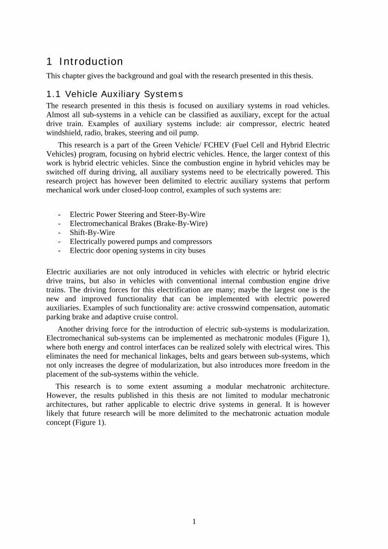
Another driving force for the introduction of electric sub-systems is modularization. Electromechanical sub-systems can be implemented as mechatronic modules (Figure 1), where both energy and control interfaces can be realized solely with electrical wires. This eliminates the need for mechanical linkages, belts and gears between sub-systems, which not only increases the degree of modularization, but also introduces more freedom in the placement of the sub-systems within the vehicle.
This research is to some extent assuming a modular mechatronic architecture. However, the results published in this thesis are not limited to modular mechatronic architectures, but rather applicable to electric drive systems in general. It is however likely that future research will be more delimited to the mechatronic actuation module concept (Figure 1).
2
Sensors
EnergySource / Buffer
Controller
Automatic Control
Software Electronics
LoadPower electronicsConverter /Driver
Electromechanicalactuator
Transmission /Linkage
Physical mechatronic module
DiagnosticsCommand from driveror other sub-system
Figure 1. Block diagram of a general mechatronic module.
1.2 Mechatronics Design Methodology A mechatronic system spans over several engineering disciplines: mechanical engineering, electrical engineering, control engineering and computer science (Figure 1). Separately applying the available domain specific design and optimization methods to a mechatronic system will not result in an optimal system design. For example, parameters like inertia and motor torque depend on the system’s size and geometry and can only be optimized in common. The drawbacks with the traditional methodologies for mechatronic design mostly appear in the interfaces between the different domains, for example:
The design of the controller and the structure to be controlled (plant) is often separated. Therefore the control engineers have to design a controller for an already existing physical system. Hence, few aspects from a control perspective have been considered in the design process of the mechanical system, resulting in a system with non-optimal dynamic performance.
Furthermore, the design of the electromechanical actuators (motors and gears) is often completely separate from the design process of the system to be actuated. This most probably results in non-optimal actuators for the application. This is acceptable in low volume applications, since it often is too expensive to develop application specific actuators. However in the context of this work, automotive systems, designing application specific actuators, can in many cases reduce the overall cost, due to the very large production volumes.

3
1.3 Goal The goal with this research is to develop a design and optimization methodology for mechatronic modules. The aim is to treat all important phenomena from all involved engineering domains in one single process. This is however only possible for a relatively small number of design parameters, therefore the target of this methodology is concept evaluation, early in the design process. In later stages of the development process, the number of design parameters may be huge; also the number of involved design engineers may be large. Hence, it is very hard to apply any analytical design or optimization method on the system level during the later stages of the design process.
As mentioned above the scope of this methodology is conceptual design, the idea is to model all of the candidate concepts/configurations and then optimize them with respect to the same criteria. Primary optimization criteria targeted in this work are:
- Weight - Size / envelope - Efficiency
Performance is in this research treated as a design requirement. The goal with the design methodology is to find the system that precisely fulfills the performance requirements and is optimal with respect to one or several of the above optimization criteria.
Paper A describes the background and goal with the research in more detail.
1.4 Research approach Each auxiliary system is designed to have some explicit functionality. The
requirements on an electromechanical sub-system are therefore unique for that individual sub-system. Some of the sub-systems are for example very safety-critical, which sets high requirements on reliability and redundancy, while others are non-safety critical. Hence, the design aspects (or design parameters) of most importance depend on the particular sub-system. This implies that it is very difficult to find a general overall design methodology that covers all aspects of a general electric auxiliary system. If one specific sub-system is analyzed it is of course possible to identify a number of crucial design parameters and also to find optimal design solutions for that specific sub-system. Therefore, one possible research approach would be to analyze each auxiliary system separately and find the optimal design of each sub-system. This approach is however very time consuming, and the results would only be applicable to the specific context of each design case.
The approach taken in this research is however to focus on the similarities between the different sub-systems. The goal is to find general design methods that are applicable to all closed-loop controlled electromechanical sub-systems, in both commercial and private vehicles. These methods will be useful in mechatronic sub-system design projects in general, but they will not solve all design problems and sometimes not even address the most important or difficult design problems (e.g. in safety critical systems).
The goal is reached by starting with a thorough analysis of the “heart” of a mechatronic module, the electric motor, within only a few domains, and then extending the analysis component by component and domain by domain. The number of design parameters is kept reasonably low by only including the central parameters of each component and domain into the analysis. This relatively small number of design parameters, enables
4
analytical solutions to most of the design and optimization problems included in the methodology. Hence, the target of this design methodology is conceptual design, where the number of design parameters are low in comparison to the later design stages.
So far no sub-system has been analyzed in more detail, the research has been focused on general design issues in mechatronic design. The differences between the different sub-systems have been considered only as different load characteristics. All research has been based on mathematical component models derived from basic physical relations. The mathematical models have, when possible, been verified against available component data. The sizing methods are based on well accepted mathematical models of different physical phenomena and on standardized dimensioning methods. It is however necessary to verify the derived methods on specific sub-system design cases in future research (see section 4).
The approach is so far based on static component models, enabling symbolic solutions of many of the derived equations. Dynamic models and simulations are of course necessary to verify the optimized configuration, but simulations are not necessary for the actual sizing and optimization.
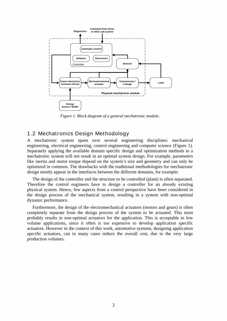
1.5 Focus: Servo motor and gearhead The research area described above is large and all aspects of it can not be treated in parallel. It was decided to begin by analyzing the motor and gearhead design/selection problem. Therefore the research presented in this thesis is mainly delimited to the problem of finding the optimal electric motor and gearhead for an (mechatronic) application, given a specified load.
Motor GearHead Load shaft
SupplyEarthInverter
Figure 2. Electric drive system
The design methods presented in the appended papers focus on the two components within the dashed line in Figure 2 (motor and gearhead). However, both the load and the inverter are also to some extent included into the methodology. The cost of the inverter may constitute a large part of the total system cost. Therefore it may be important to design the motor and gearhead in such a way that it minimizes the inverter cost.
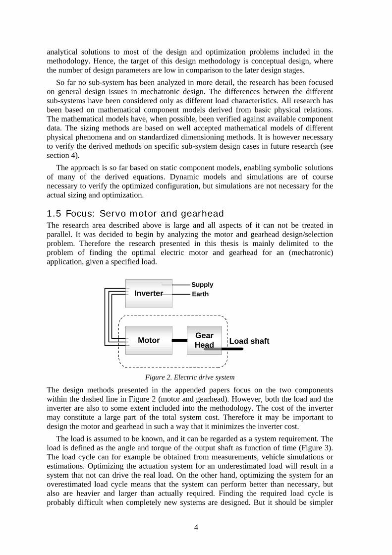
The load is assumed to be known, and it can be regarded as a system requirement. The load is defined as the angle and torque of the output shaft as function of time (Figure 3). The load cycle can for example be obtained from measurements, vehicle simulations or estimations. Optimizing the actuation system for an underestimated load will result in a system that not can drive the real load. On the other hand, optimizing the system for an overestimated load cycle means that the system can perform better than necessary, but also are heavier and larger than actually required. Finding the required load cycle is probably difficult when completely new systems are designed. But it should be simpler
5
for automotive systems since cars and trucks are available, loads can be measured or simulated with quite high accuracy. The cycle time of the load cycle used for dimensioning must be significantly shorter than the thermal time constant of the motor. Hence, the difficulties probably lies in identifying the worst part of the load cycle (or worst use case) and not in obtaining the torque and position data. However, this has not been investigated further in this research and here it is assumed that the worst case load cycle is known.
0 0.5 1 1.5 2 2.5 3 3.5 4 4.5 5
−200
−100
0
100
200
Time [s]
Load Cycle, Position (Angle) and Torque of Outgoing Shaft as Function of Time
Ang. Velocity [rad/s]Angle [rad]
0 0.5 1 1.5 2 2.5 3 3.5 4 4.5 5
−4
−2
0
2
4
Time [s]
Tor
que
[Nm
]
Figure 3. Example of a load cycle, output position (angle) and torque,
required as input to the sizing methods.
A number of assumptions have been introduced during the work; the ones concerning modeling details are presented in the appended papers. The following assumptions are however more or less used in all of the appended papers:
− The sub-system configuration, component types and material properties are assumed to be given (known). The methodology aims at, from a given configuration of components, find the best component dimensions with respect to some criteria. Parameters related to the component type and material properties (e.g. motor type, gear type, bending fatigue limit of gear material, etc.) are also required as input.
− The worst case load cycle is assumed to be known. The load cycle can be regarded as a part of the system specification and input to the methodology.
− Rotational load is assumed. So far the methodology only includes rotational elements (motor and gear), the plan is however to include linear motion components in the future.
− The sub-systems are assumed to be designed to have a long life time (infinite life dimensioning). The methods presented assumes a large number of load cycles, this is especially true for the gear sizing models presented in report C.
6
− The copper losses (RI2) are assumed to constitute the major part of the motor losses. All other losses (iron, friction, etc) are assumed to be small. In other words the motor losses are assumed to be independent of speed, an assumption often made in methods for motor selection. The correctness and implications of this assumption must however be investigated in future research (see section 4.1).
− Mechanical fatigue is assumed to set the limit on the gear size. This is the traditional approach to gear design; in some cases, however, heat or other requirements might limit the minimum gear size.
− The bearings are assumed to not limit the design in any aspect. In some cases the bearings might limit the size or life-time of for example a gearhead; here it is assumed that that not is the case.
− Weight and inertias of the mechanical shafts are generally assumed to be low. The weights and inertias of the motor and the gears are assumed to be much larger than the inertias and weights of the shafts.
7
2 Summary of appended papers Paper A: Towards a design and optimization methodology for automotive mechatronics This paper describes the background and goal with this research. It summarizes the previous and parallel work within the area of mechatronic design methodologies. It is concluded that much of the previous work has a control engineering focus. For example methods for structure optimization with respect to control performance (integrated structure and control design). The goal and approach with this research is described in detail in this paper.
Paper B: Optimal design of motor and gear ratio in mechatronic systems Here a method for optimal design of motor and gear ratio is presented. The method, in comparison with many of the previous methods, is applicable to any kind of load, both inertial and constant speed. It approaches the problem in a different way than most of the previous published methods. Instead of finding the best motor from a given set of motors, the method is used to calculate a range of motor dimensions and gear ratios that represents motor/gear ratio combinations that are precisely powerful enough to drive the given load. From this range of motor dimensions the best motor/gear ratio combination with respect to motor weight, size or peak power requirement can be selected. For systems produced in high volumes, these optimal dimensions may be used to design a new motor. For a low volume application, a motor with similar dimensions may be selected. The motor torque model derived and used in this paper is verified against existing motor data (motor catalogues).
Report C: Relations between size and gear ratio in spur and planetary gear trains This report focuses on gear design. Fairly detailed models of the necessary size of spur gear trains are derived. The derived models are based on the Swedish standards for spur gear geometry and spur gear dimensioning. These models can be used to predict the size of a spur or three-wheel planetary gear train as function of gear ratio and output torque. Further on, the equations present the gear inertia, shape and mass as function of output torque, gear ratio and gear width. Even though these models can be used for any kind of application requiring a gear, they have mainly been derived with the intention to be used in design and optimization of electromechanical servo drives.
The derived models confirm what has been well known for a long time in the area: For a given load, three-wheel planetary gears require less volume and mass compared with single spur gear pairs. Also the inertia of a planetary gear train is shown to be much lower than for the corresponding spur gear pair.
8
Paper D: Optimal selection of motor and gearhead in mechatronic applications In contrast to the papers above, this paper presents a discrete method for servomotor and gearhead optimization. The method allows the best motor/gearhead combination to be selected from a given set of motors and gearheads. This method can therefore be useful in applications where it is not an option to design a new motor and gearhead, for example in low and medium volume applications. In contrast to most of the previously published methods for motor selection, this method does not assume an ideal gearhead. Furthermore it can handle any type of load and the final selection criterion is up to the user. It can be used for performance optimization, weight minimization, maximization of energy efficiency and also for peak power minimization.
9
3 Conclusions The research has so far mainly considered the structural properties of an actuation module. Dynamic and control properties have not yet been considered. The plan is however to include the system dynamics and control later on, as discussed in section 4 below. From the structural design point of view, a number of conclusions can be made, the main ones are:
The gear ratio has a great impact on the necessary motor size, regardless of load type. Paper B shows that the choice of gear ratio to minimize the motor size is rather complicated and not always intuitive. However, the proposed method can, for any given load, find the smallest possible motor/gear ratio combination.
The results from report C indicate that three-wheel planetary gears can transmit more torque and has significantly less inertia than conventional pinion and gear-wheel pairs. The derived equations for the necessary gear sizes are rather complicated and include many parameters. However, as stated in the report, it is generally the flank pressure that limits the gear size, and the flank pressure is almost independent of the number of teeth. This makes it possible to use simplified versions of the gear models in future research.
In paper D it is shown that, in practice, the gearhead generally has significantly lower inertia and weight than the motor. This implies that the approach with an ideal gear used in paper B was rather good. Nevertheless, the results presented in paper D also imply that using an ideal gear model might result in the selection of a too small motor that can not drive the load. Moreover the gear weight and inertia may be of significance when large gear ratios are required.
A more general conclusion can be drawn from the research presented in the appended papers: A direct drive configuration is generally not optimal from an actuator weight or size perspective. Only in applications where the speeds are close to the motor’s maximum speed a direct drive configuration may minimize the size and weight. However, a direct drive setup may be more efficient than if a gearhead is used, especially if none of the regenerated electricity is stored. For example, in an inertial load application with a size optimized motor and gear ratio, approximately half of the electric energy is used to accelerate the motor’s rotor. If none of the regenerated energy during deceleration is stored, the maximum theoretical efficiency is 50%, and in reality much lower. Using a direct drive configuration would increase the efficiency but also increase the size and weight of the electric motor. However, a direct drive setup may have a number of other advantages over a configuration with a gearhead, direct drives have for example no backlash and are known to have better back-driveability.
10
4 Discussion and Future Research Two things remain before the planned work with the design methods and models for motor and gearhead presented in this thesis are complete. First of all, the plan is to combine the motor models from paper B with the gear models presented in report C. This will result in a method that can optimize the motor and gearhead system with respect to weight, power or size. The other planed task is to apply the methodology on a real design case. It is likely that this case study will be performed in close cooperation with Scania CV AB. Electric power-steering, starter motor and electric door opening systems have been discussed as possible case studies.
In addition to the planned research described above, some other ideas for future research are presented in the following sections.
4.1 Loss modeling and heat From the research presented in this thesis it is apparent that drive system optimization often results in high motor speeds (large gear ratios). This may constitute a problem since the motor and gear models used so far do not include any speed dependent losses. This may result in that the motor gearhead combination selected by the sizing method can not, without overheating, drive the load. It is therefore necessary to investigate how large impact these un-modeled phenomena have on the result, and how large the different types of losses are.
Motor losses are generally classified into four groups: copper losses, iron losses, stray losses and mechanical losses (e.g. Urasaki et al. 2000). Deng (1999) presents an approach for estimation of the iron losses in PM brushless machines. The approach is based on the fundamental concept that eddy current losses are proportional to the square of the time rate of change of the flux density. According to Deng this loss model has a very good agreement when compared to losses in existing motors. Yoo et al. (2003) use models of resistive, core and friction losses to boost actuator performance. They are treating the motor as a highly non-linear device and are able to improve the actuator performance by using a non-linear, application optimized, control method.
The size optimization results in that the temperature of the actuation system may be close to its limits. Minimizing the size of the motor is equal with maximizing the motor temperature. Depending on gear efficiency the gears are also generating more or less heat. Further on, if the power electronics are integrated in the same physical module, there will be a lot of heat to dissipate from the actuation module. This might constitute a problem; maybe a method for heat analysis must be included into the methodology. The integration of control electronics into the same physical module may require the allowed temperature of the actuation module to be lowered.
Before it is possible to analyze the heat and temperature of the actuation module it is necessary to include non-ideal models of the power electronics. This is of course also important from a system efficiency evaluation/optimization point of view.
4.2 Local energy storage / super capacitors Depending on load type, the use of local super-capacitors as storage for the regenerated electric energy may have the possibility for a drastic increase of system efficiency. The use of super capacitors and regenerative braking are mainly considered for use in electric and hybrid vehicle traction, but they can of course also be used in the auxiliary systems.

11
Capacitors can not compete with batteries in the sense of energy density, but they present better power density and can be charged and discharged thousands of times without performance deterioration (Dixon et al. 2002). Therefore they are ideal as temporary local energy storages in mechatronic systems.
Izumi et al. (1995) store the regenerated energy from a DC-motor in the DC bus side capacitor of the inverter. The circuit used is very similar to a standard four-quadrant inverter; just a diode has been added between the DC-supply and the DC-bus capacitor, which has been replaced with a super capacitor. They have designed an optimal controller to minimize the energy consumption of the servo system. Their experiments show that it is possible to achieve an efficiency close to 100% of the maximum theoretical efficiency for that particular setup.
In the context of this research it would be interesting to evaluate the possible efficiency improvements with local super capacitors. A certain level of increased system cost will be acceptable if the system consumes less electric energy. Moreover, different control concepts need to be investigated, e.g. how to control the transistors in the full bridge converter to regenerate as much energy as possible. The control concept should preferably also be transparent, such that the motor drive behaves as an ordinary current controlled motor drive. This could also be the starting point for the inclusion of non ideal driver electronics into the methodology. The losses in the inverter can be significant and the inverter also represents a large system cost. Therefore, non-ideal power electronics models have to be included for system level optimization.
4.3 Variable transmission ratios and linear motion It would be interesting to investigate if variable transmission ratios can increase the actuation performance or lower the actuation system’s weight. Variable transmission ratios can be achieved either by using a compact discrete multi-speed transmission or by using a continuously variable transmission (CVT), with an infinite number of gear ratios. A compact and cheep variable speed transmission may, while keeping the speed range, enhance the torque density of the actuator compared to a fixed gear ratio configuration.
Hamel and Widner (1997) and Hamel et al. (2003) have developed dynamic models of variable gear ratio transmissions for robotic applications. They have also investigated different gear ratio control concepts for performance optimization. They claim that variable transmission-ratio gears extend the performance range of electric actuators into the range normally held by hydraulic actuators. Their focus is robotic applications, but their results should be possible to apply to vehicle sub-systems as well.
Hirose et al. (1999) describes a very interesting type of lead screw, the x-screw, which incorporates a CVT. So far only rotational motion has been considered within the research described in this thesis, but many of the in-vehicle systems require linear motion. To optimize linear-motion actuators it is necessary to develop similar models for lead screws as the gearhead models described in report C. For this, the x-screw concept appears very interesting. Consider for example an electric power steering system, where high torques but low speeds are needed for parking maneuvers, while higher speeds and lower torques are needed during high-speed driving.
Another very interesting possibility with variable transmission ratios is the possibility of efficiency enhancements. Variable transmissions mean that the gear ratio can be controlled in such a way that the motor runs in its region of maximum efficiency. Even though this might be more interesting for applications with more of constant speed characteristics, it would be a good idea to investigate the possible energy saving effect in
12
general. Kim et al. (2000) use a CVT to improve the efficiency of a battery powered mobile robot. Their results indicate a 25% longer run time than robots employing a fixed reduction ratio.
Field weakening is sometimes introduced in motor drives to enable higher motor speeds than the bus voltage otherwise would allow. This is especially used in traction motors to reduce the cost of the power electronics (lower peak current), but can of course also be used in motor drives for auxiliary systems. It would be interesting to compare field weakening contra gear ratio selection and also contra variable speed transmissions.
4.4 Integrated control and structure design So far only structural properties of an actuation module have been considered. The plan is to also include performance simulations and controller design into the methodology. Position accuracy and system performance depend both on the controller and the physical structure, and they can therefore only be optimized if the structure and the controller are designed in parallel. Furthermore, the control strategy and the controllability of the system may affect the system efficiency.
Job van Amerongen et al. (2003) have done much research in the area of integrated modeling and design of mechanical structure and controller. Their idea is to use control design models that, besides the parameters of the controller, maintain all relevant physical parameters of the plant (physical structure). Their focus is however on design and optimization of system dynamics (control engineering focus), their models and methods do not cover any static parameters, as for example weight or envelope. The approach is nevertheless very interesting and it maps nicely into this research. Paper A, discusses this area in a bit more detail.
The conflict between accuracy and speed requirements are discussed by Cetinkunt (1991). He states that the accuracy increases with gear ratio while the acceleration (cycle time) performance decreases, at least for inertial loads. His analysis is however not made from dynamic simulations or physical models, he rather reason his way to this result. It would be interesting to investigate this for general loads and non ideal gears with a more analytical approach. Moreover, if the position sensor is placed on the motor shaft and has a fixed resolution, a high gear ratio means higher resolution on the load position than a low ratio. So this is something that also has to be considered when the gear ratio is selected.
4.5 Other issues for future research The extensive functionality and complex structure of mechatronic systems means that it generally is not enough to optimize on a single criterion, often a multi-objective optimization is needed. Furthermore, the component models are non-linear, suggesting a need for non-linear optimization methods. In the research presented in this thesis, it has been possible to visualize the results in 3-D plots. If the number of free design-parameters is increased, for example by concurrent design of all components, it is no longer possible to find the optimal solution graphically. Therefore there might be a need to incorporate multi criteria, non-linear optimization methods into the methodology.
As discussed earlier, it has been assumed that the worst case load cycle is known, but this is not always the case in reality. First of all the load cycle might not at all be available and if it is, it may be very difficult to identify the worst part of it. Methods or guidelines on how to find the worst part of a load cycle would be an interesting topic for future research.
13
5 References Cetinkunt S. (1991), Optimal Design Issues in High-Speed High-Precision Motion Servo Systems, Mechatronics-The Science of Intelligent Machines-An International Journal, pp 187-201, vol 1, No 2, 1991. Deng F. (1999), An Improved Iron Loss Estimation for Permanent Magnet Brushless Machines, IEEE Transactions on Energy Conversion, vol 14, No 4, December 1999. Dixon J. W., Ortúzar M. E. (2002), Ultracapacitors + DC-DC Converters in Regenerative Braking Systems (2002), IEEE Aerospace and Electronic Systems Magazine, vol 17, no 8, pp 16-21 Hamel W.R., Widner T. C. (1997), Transmission-Based Electrical Actuators: A Concept for Improving Robot Manipulator Performance, Proceedings of the 1997 IEEE International Conference on Robotics and Automation, pp 1208-1215, Albuquerque, New Mexico, April 1997. Hamel W.R., Kim S, Zhou R, Lumsdaine A. (2003), Dynamic Modeling and Analysis of a Transmission-based Robot Servoactuator, Proceedings of the 2003 IEEE International Conference on Robotics and Automation, pp 208-213, Taipei, Taiwan, September 2003. Hirose S., Tibbets C., Hagiwara T. (1999), Development of X-screw: A Load-Sensitive Actuator Incorporating a Variable Transmission, Proceedings of the 1999 IEEE International Conference on Robotics & Automation, pp 193-199, Detroit, Michigan, may 1999. Izumi T., Boyagoda P., Nakaoka M., Hiraki E. (1995), Optimal Control of a Servo System Regenration Conservative Energy to a Condenser, Proceedings of the IEEE/IAS International Conference on Industrial Automation and Control: Emerging Technologies, pp 651-656, May 1995. Kim J., Yeom H., Park F. C., Park Y. I., Kim M. (2000), On the Energy Efficiency of CVT-Based Mobile Robots, Proceedings of the 2000 IEEE International Conference on Robotics & Automation, San Francisco, CA, April 2000. Urasaki N., Senjyu T., Uezato K. (2000), Influence of All Losses on Permanent Magnet Synchronous Motor Drives, In proceedings of IECON, the 26th Annual Conference of the IEEE, pp 1371-1376, October 2000. Van Amerongen J., Breedveld P. (2003), Modelling of physical systems for the design and control of mechatronic systems, Annual Reviews in Control, vol 27, pp 87-117, 2003. Yoo J. G., Ashok P., Kapoor C., Tesar D. (2003), Operational Performance Criteria for Intelligent Actuators, Department of Energy (DOE)-URPR Deliverable report for FY03, The Robotics Research Group at The University of Texas Austin, January 2003. http://www.robotics.utexas.edu/rrg/research/actuator/, Accessed 041219.


![[Osman Bilen] the Historicity of Understanding and(BookZZ.org)](https://img.pdfslide.us/doc/110x75/577c7c2f1a28abe05499a3cb/osman-bilen-the-historicity-of-understanding-andbookzzorg.jpg)