Embed Size (px)
Citation preview

ON-BOARD DIAGNOSTICS SCANNER
Hardware graduation project
Supervisor: Dr. Samer Arandi
Prepared by: Ahmad Saqfalhait & Morad Abushamma

Outline 2
Background
High Level View
Protocols
User Interface
Storage Unit
Hardware Implementation
Similar System
Limitations
Standers
PLC Project

Background 3
Nowadays cars are very essential element in people`s life, and it`s
maintenance has a great consideration. In the early 1980s a new system that helps in
car maintenance has been introduced which is on-board diagnostics system “OBD” a
self-diagnostic and reporting system, It gives the repair technician and the car owner
the ability to access the health information of a vehicle, sensors and many parameters,
this system has been evolved and now it became a mandatory requirement in car
industry.

Introduction 4
OBD scanner standalone device that will give the user the capability to
request diagnostic data form the car through an interactive interface based on
appropriate communication interface, storage unit and processing unit.
OBD scanner is OBD-II standard compliant so it supports almost all cars
manufactured after 1996 and this device has three main functions: view current and
Freeze frame data, Read and clear generic and manufacturer specific diagnostic
trouble codes and Retrieve vehicle information.

High level view 5
PIC Microcontroller Engine control unit
Group of push buttons (System Input)
Graphical LCD
EEPROMCommunication
Interface

Protocols and communication interface 6
A group of protocols should be implemented in the OBD scanner device
in order to support all OBD-II compliant cars. Each protocol has physical, data link
and application layer specifications.
The protocols are:
ISO15765-4 (CAN-BUS) (mandatory for 2008+ cars)
ISO14230-4 (KWP2000) (Very common protocol for 2003+)
ISO9141-2 (ISO) (the oldest protocol)
SAE J1850 (VPW) (GM vehicles)
SAE J1850 (PWM) (Ford vehicles)

OBD II Cable 7
ISO 9141 8
Message Format
Frame structure
Tail
Type Target Address Source Address Byte #1 Byte #2 Byte #3 Byte #4 Byte #5 Byte #6 Byte #7 CS
Request 68 6A F1
Response 48 6B ECU Physical Address
Header bytes Data bytes
7 Data bytes (max)
7 Data bytes (max)
Start Bit "0" bit 0 bit 1 bit 2 bit 3 bit 4 bit 5 bit 6 bit 7 Stop Bit "1"
9
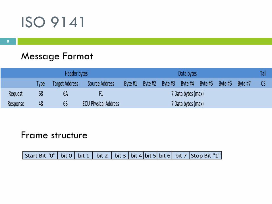
ISO 9141
5-baud
Initialization
Start
Send Initialization sequence 33hex
at 5 bit/s
ISO9141 5-baud initialization
Waite for synchronization byte 55 hex
Reconfigure to the new baud rate 10.4 kbps
55 hex received
Wait for two key bytes
Key bytes in {(08,08),(94,94)}
Send ACK (invert key byte #2)
Wait for “ready to communicate” signal
Invert of initialization
sequence (33 hex) received
ISO9141 compliant Failed
Timeout
no
Timeout
yes
no
yes
Timeout
no
yes

ISO 9141 Interface 10
ISO9141 is an asynchronous serial data protocol with 10.4 baud rate,
similar to RS232 in timing and frame structure and differs in signal levels with 12 V
as logic 1 and 0 V as logic 0, one bidirectional line used to transmit and receive
data known as K-Line.

ISO14230 (KWP2000) 11
Message Format
Frame structure
KWP2000 5-baud initialization and hardware interface same ISO 9141
Tail
Format Byte Target Address Source Address Byte #1 Byte #2 Byte #3 Byte #4 Byte #5 Byte #6 Byte #7 CS
Request 11LL LLLL 33 F1
Response 10LL LLLL F1 ECU Physical Address 7 Data bytes (max)
Header bytes Data bytes
7 Data bytes (max)
Start Bit "0" bit 0 bit 1 bit 2 bit 3 bit 4 bit 5 bit 6 bit 7 Stop Bit "1"

KWP2000 Fast Initialization 12
Tidle Tinil
T wup
Tinil Twup
25 50
Data bytes Tail
Format Byte Target Address Source Address Byte #1 CS
C1 33 F1 81 66
Header bytes
Tail
Format Byte Target Address Source Address Byte #1 Byte #2 Byte #3 CS
83 F1 10 C1 YY ZZ CS
Header bytes Data bytes
WAKE UP PATTERN
START COMMUNICATION REQUEST
START COMMUNICATION POSITIVE RESPONSE
Start
Send wake up pattern
Send Start Communication Request
Wait for Start Communication response
ISO14230 (KWP2000)compliant
Start Communication response received
yes
Failed
no

ISO15765 (CAN-BUS) 13
Versions
CAN Protocol is mandatory for 2008+ cars
Version NO. Identifier length Baud rate
1 11 bit 500 Kbaud
2 29 bit 500 Kbaud
3 11 bit 250 Kbaud
4 29 bit 250 Kbaud
CAN Initialization
Start
Functional 11 bit CAN identifier
request message
11 bit CAN identifier response handling
Functional 29 bit CAN identifier
request message
29 bit CAN identifier response handling
ISO15765-4 compliant
Failed
TX ERROR
No response29 bit CAN ID verified
TX Done
No response
11 bit CAN ID verified
TX ERROR
TX Done
Input: Baud Rate

14
CAN RESPONSE HANDLING CAN REQUEST MESSAGE TRANSMISSION
Transmit functional request message ,service $01(supported PID`s)
CAN Error
Tx Done
Succeed Failed
yes
no
yes
no
Start P2CAN timer
P2Can Timeout
yes
no
Response Started
yes
no
Receive Response
P2CAN timeout and all started responses
completely received
yes
no
BusyRepeatRequest negative response
Number of retries elapsed
Any other negative response
no
yes
yes
no
no
yes
succeed Failed Resend Request Failed

CAN Signaling specifications 15
CAN Bus has two line CANH and CANL, logic is determined by both line
level:
Logic 1: Recessive or idle bus state: CANH and CANL signals are not
driven
Logic 0: Dominant or active bus state: CANH driven high while CANL
driven low
CANH signal voltage level: 3.5V
CANL signal voltage level: 1.5V

Can Interface 16

Data inquiry 17
Message Format
Mode List
MODE PID
Mode (hex) Description
1 Show current data
2 Show freeze frame data
3 Show stored Diagnostic Trouble Codes
4 Clear Diagnostic Trouble Codes and stored values
5 Test results, oxygen sensor monitoring (non CAN only)
6 Test results, other component/system monitoring (Test results, oxygen sensor monitoring for CAN only)
7 Show pending Diagnostic Trouble Codes (detected during current or last driving cycle)
8 Control operation of on-board component/system
9 Request vehicle information
0A Permanent Diagnostic Trouble Codes (DTCs) (Cleared DTCs)

MODE 1 PID List 18
PID (hex) bytes returned Description
0 4 PIDs supported [01 - 20]
1 4 Monitor status since DTCs cleared. (Includes malfunction indicator lamp (MIL) status and number of DTCs.)
2 2 Freeze DTC
3 2 Fuel system status
4 1 Calculated engine load value
5 1 Engine coolant temperature
6 1 Short term fuel % trim—Bank 1
7 1 Long term fuel % trim—Bank 1
8 1 Short term fuel % trim—Bank 2
9 1 Long term fuel % trim—Bank 2
0A 1 Fuel pressure
0B 1 Intake manifold absolute pressure
0C 2 Engine RPM
0D 1 Vehicle speed
0E 1 Timing advance
0F 1 Intake air temperature
10 2 MAF air flow rate
11 1 Throttle position
12 1 Commanded secondary air status
13 1 Oxygen sensors present

OBD Error codes 19

User Interface 20
User interact with the device via:
• Input: Push Button
• Output: GLCD

Input: push buttons 21

Input: push buttons – Proteus & PCB
Design 22

Output: Graphical LCD 23
We have used GLCD (with t6963c controller) to present the output
for the user.
Why this GLCD ?
It supports text and graphical modes
It supports custom character – Arabic feature.
Available Recourse.

Output: Graphical LCD - Software 24
Paging and select functions.
Menu

Output: Graphical LCD - Software 25

Output: Graphical LCD – Custom Char 26
Process Generate array of hex values for every Arabic letter in all of its forms (connected
and disconnected letter).
Store characters’ hex values at the EEPROM.
Character’s mapping address.
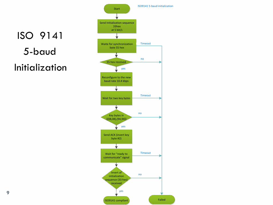
The whole system (input and output)
27

Storage unit EEPROM 28
We used 24LC256 EEPROM.
We stored 3 types of data:
Errors’ codes.
Manufacturers.
History (last Scan result).
Data stored at the Microcontroller’s memory.
Main Sections Table
Sections Address
Header 0Xxxxx– 0Xxxxx
Manufacturers and Codes - English 0Xxxxx– 0Xxxxx
Manufacturers and Codes - Arabic 0Xxxxx– 0Xxxxx
Description - English 0Xxxxx– 0Xxxxx
Description - Arabic 0Xxxxx– 0Xxxxx
History 0Xxxxx– 0Xxxxx
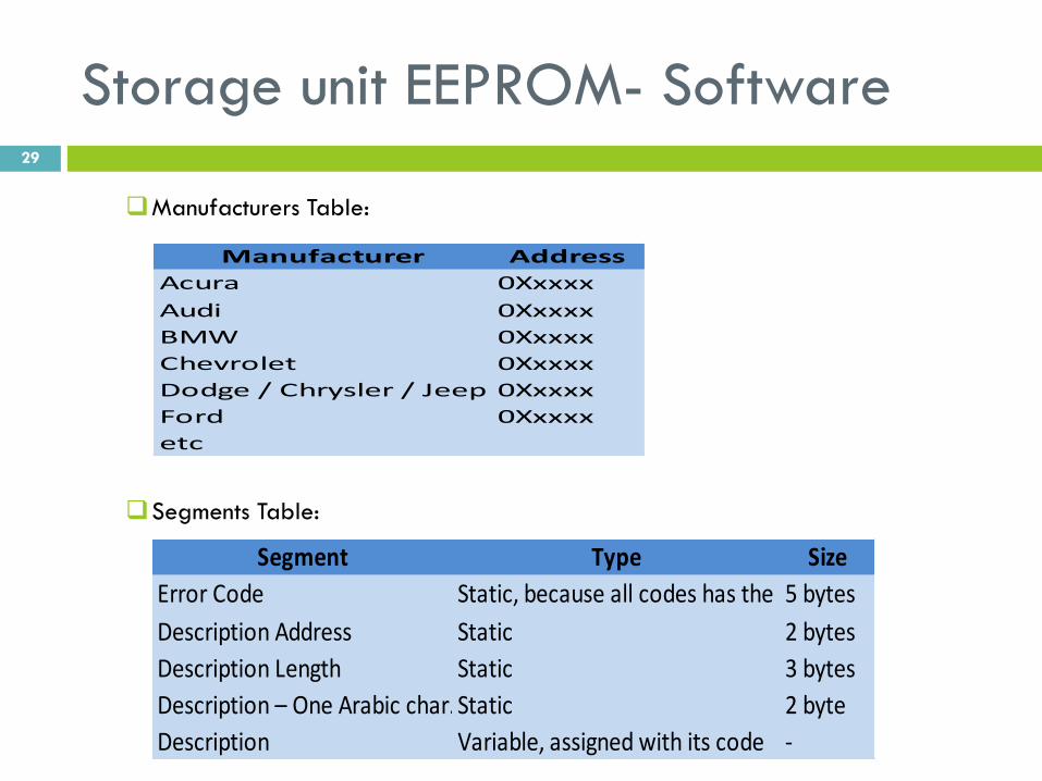
Storage unit EEPROM- Software 29
Manufacturers Table:
Segments Table:
Manufacturer Address
Acura 0Xxxxx
Audi 0Xxxxx
BMW 0Xxxxx
Chevrolet 0Xxxxx
Dodge / Chrysler / Jeep 0Xxxxx
Ford 0Xxxxx
etc
Segment Type Size
Error Code Static, because all codes has the same length5 bytes
Description Address Static 2 bytes
Description Length Static 3 bytes
Description – One Arabic char. (Unicode)Static 2 byte
Description Variable, assigned with its code -

Storage unit EEPROM – Proteus & PCB
Design 30

Hardware implementation – Eagle
schematic 31

Hardware implementation – Eagle
Printed circuit design 32

Hardware implementation –
Screenshoots 33

Similar systems 34
D900
Standalone OBD scanner is connected to the OBD interface on car
directly and supports the five main communication protocols.

Limitations 35
Standards availability
On-board diagnostics system has five common communication protocols, this protocols specifics the communication process between the OBD scanner and the car ECU. These protocols are ISO standards, not available for free and the average price for each protocol 100-200$. This problem has been solved after a long search for free documents that describe the required details about each protocol.
Testing environment
Our testing environment is cars, and for each protocol we need different type of cars, we could not find a car ECU emulator which will ease testing process, also we faced problems in finding people who will let us make our testing on their cars.
Time
The available period for graduation project implementation which is four months is very adequate, but unfortunately we spent two and a half months on another project (implementing home automation system through home electrical network) but we have faced many problems that forced us to change the idea so we worked on OBD Scanner project for the half of the period.
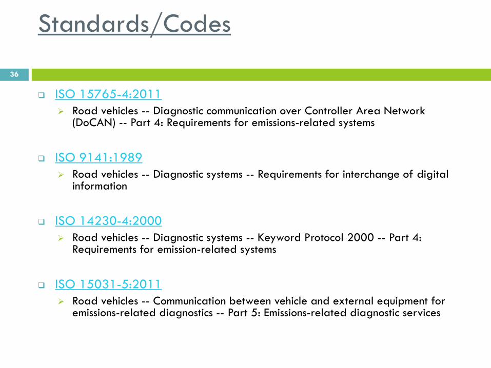
Standards/Codes
36
ISO 15765-4:2011
Road vehicles -- Diagnostic communication over Controller Area Network (DoCAN) -- Part 4: Requirements for emissions-related systems
ISO 9141:1989
Road vehicles -- Diagnostic systems -- Requirements for interchange of digital information
ISO 14230-4:2000
Road vehicles -- Diagnostic systems -- Keyword Protocol 2000 -- Part 4: Requirements for emission-related systems
ISO 15031-5:2011
Road vehicles -- Communication between vehicle and external equipment for emissions-related diagnostics -- Part 5: Emissions-related diagnostic services
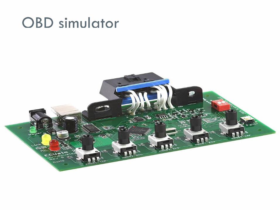
OBD simulator 37

PLC Project 38
About
A remotely controlled electrical plug system which applies functionalities like (on
& off) operations, timed operations and power readings. The brilliant idea here
is the communication medium, its neither WIFI nor Bluetooth which always raise
the costs; the electrical signals of electricity home network are used to
communicate with plugs.
Technology
Power line carrier communication

PLC Project-power line carrier modem 39

PLC Project - Problems 40
Printed circuit design of NCN 49597
Special circuit components availability
High speed printing requirements

PLC Project-PLC evaluation board 41
C2000 Power Line Modem Developer's Kit
($599.00)

42
Thanks