Embed Size (px)
Citation preview
ASTRALPOOL HEAT II ASTRALPOOL HEAT II ASTRALPOOL HEAT II ASTRALPOOL HEAT II HEAT PUMPHEAT PUMPHEAT PUMPHEAT PUMP MODBUS AND AUTOMATION MANUAL V1.0MODBUS AND AUTOMATION MANUAL V1.0MODBUS AND AUTOMATION MANUAL V1.0MODBUS AND AUTOMATION MANUAL V1.0
CODE: 05470114
EDITION: 3
REFERENCES
54068-MB (B100M)
54069-MB (B150M)
54070-MB (B150T)
54071-MB (B200M)
54072-MB (B200T)
54073-MB (B250M)
54074-MB (B250T)
54075-MB (B300T)
54078-MB (R100M)
54079-MB (R150M)
54080-MB (R150T)
54081-MB (R200M)
54082-MB (R200T)
54083-MB (R250M)
54084-MB (R250T)
54089-MB (R300T)

© ASTRALPOOL 2015 ALL RIGHTS RESERVED. PROPRIETARY DOCUMENT. 2
© Fluidra, S.A. 201© Fluidra, S.A. 201© Fluidra, S.A. 201© Fluidra, S.A. 2015555. All Rights Reserved.. All Rights Reserved.. All Rights Reserved.. All Rights Reserved.
All the trademarks are registered by Fluidra SA and/or its affiliates, or its respective All the trademarks are registered by Fluidra SA and/or its affiliates, or its respective All the trademarks are registered by Fluidra SA and/or its affiliates, or its respective All the trademarks are registered by Fluidra SA and/or its affiliates, or its respective owners. Fluidra SA owners. Fluidra SA owners. Fluidra SA owners. Fluidra SA
and its licensors will own all right, title and interest to the manual, technology and information including and its licensors will own all right, title and interest to the manual, technology and information including and its licensors will own all right, title and interest to the manual, technology and information including and its licensors will own all right, title and interest to the manual, technology and information including
all portions, copies or modifications thereof.all portions, copies or modifications thereof.all portions, copies or modifications thereof.all portions, copies or modifications thereof.
Every effort has been made to ensure that the information given is correct. HowevEvery effort has been made to ensure that the information given is correct. HowevEvery effort has been made to ensure that the information given is correct. HowevEvery effort has been made to ensure that the information given is correct. However, due to continuous er, due to continuous er, due to continuous er, due to continuous
product improvement, Fluidra reserves the right to make changes to products and technical data without product improvement, Fluidra reserves the right to make changes to products and technical data without product improvement, Fluidra reserves the right to make changes to products and technical data without product improvement, Fluidra reserves the right to make changes to products and technical data without
prior notice.prior notice.prior notice.prior notice.
© ASTRALPOOL 2015 ALL RIGHTS RESERVED. PROPRIETARY DOCUMENT. 3
1.1.1.1. INTRODUCTION TO MODBINTRODUCTION TO MODBINTRODUCTION TO MODBINTRODUCTION TO MODBUS AND PRODUCTUS AND PRODUCTUS AND PRODUCTUS AND PRODUCT ................................................................................................................................................................................................................................ 4444
1.1.1.1.1.1.1.1. Principle of OperationPrinciple of OperationPrinciple of OperationPrinciple of Operation ................................................................................................................................................................................................................................................................................................................................................................................................................................................................................ 4444
1.2.1.2.1.2.1.2. Basic CharacteristicsBasic CharacteristicsBasic CharacteristicsBasic Characteristics ........................................................................................................................................................................................................................................................................................................................................................................................................................................................................................ 4444
2.2.2.2. ELECTRICAL CONNECTIOELECTRICAL CONNECTIOELECTRICAL CONNECTIOELECTRICAL CONNECTIONSNSNSNS ........................................................................................................................................................................................................................................................................................................................................ 5555
3.3.3.3. CABLE CHARACTERISTICCABLE CHARACTERISTICCABLE CHARACTERISTICCABLE CHARACTERISTICSSSS .................................................................................................................................................................................................................................................................................................................................................... 6666
4.4.4.4. BUS ISOLATION AND TEBUS ISOLATION AND TEBUS ISOLATION AND TEBUS ISOLATION AND TERMIRMIRMIRMINATION RESISTORSNATION RESISTORSNATION RESISTORSNATION RESISTORS ................................................................................................................................................................................................................ 6666
5.5.5.5. BOARD AND PANEL INDIBOARD AND PANEL INDIBOARD AND PANEL INDIBOARD AND PANEL INDICATORSCATORSCATORSCATORS ........................................................................................................................................................................................................................................................................................................ 7777
6.6.6.6. MODBUS FUNCTIONSMODBUS FUNCTIONSMODBUS FUNCTIONSMODBUS FUNCTIONS ........................................................................................................................................................................................................................................................................................................................................................................ 8888
6.1.6.1.6.1.6.1. Functions supportedFunctions supportedFunctions supportedFunctions supported ........................................................................................................................................................................................................................................................................................................................................................................................................................................................................................ 8888
6.2.6.2.6.2.6.2. Exception ResponsesException ResponsesException ResponsesException Responses .................................................................................................................................................................................................................................................................................................................................................................................................................................................................................... 8888
7.7.7.7. DEVICE DESCRIPTION ADEVICE DESCRIPTION ADEVICE DESCRIPTION ADEVICE DESCRIPTION AND CONFIGURATIONND CONFIGURATIONND CONFIGURATIONND CONFIGURATION ................................................................................................................................................................................................................................ 9999
7.1.7.1.7.1.7.1. General descriptionGeneral descriptionGeneral descriptionGeneral description ............................................................................................................................................................................................................................................................................................................................................................................................................................................................................................ 9999
7.27.27.27.2 Operation diagramOperation diagramOperation diagramOperation diagram ................................................................................................................................................................................................................................................................................................................................................................................................................................................................................................ 9999
7.37.37.37.3 Address and baud rate selectionAddress and baud rate selectionAddress and baud rate selectionAddress and baud rate selection ................................................................................................................................................................................................................................................................................................................................................................................................................ 9999
7.3.1 Address setting ........................................................................................................................... 9
7.3.2 Baud rate selection ................................................................................................................... 10
7.47.47.47.4 BroadcastingBroadcastingBroadcastingBroadcasting ................................................................................................................................................................................................................................................................................................................................................................................................................................................................................................................................ 10101010
8888 OPERATION MODESOPERATION MODESOPERATION MODESOPERATION MODES ................................................................................................................................................................................................................................................................................................................................................................................ 11111111
8.28.28.28.2 BASIC OPTIONSBASIC OPTIONSBASIC OPTIONSBASIC OPTIONS ................................................................................................................................................................................................................................................................................................................................................................................................................................................................................................................ 11111111
8.2.1 TECHNICAL CONFIGURATION OPTIONS................................................................................... 11
8.2.2 REQUEST WORD........................................................................................................................ 11
8.2.3 CHECKING STATUS .................................................................................................................... 12
8.2.4 TEMPERATURE PROBES READINGS .......................................................................................... 13
8.2.5 DIGITAL INPUTS ......................................................................................................................... 13
8.2.6 REAL TIME ALARMS .................................................................................................................. 14
8.2.7 ALARMS MEMORY .................................................................................................................... 15
8.2.8 CHECKING COUNTERS .............................................................................................................. 16
8.2.9 ALARM HISTORY ........................................................................................................................ 17
9999 BASIC MODBUSBASIC MODBUSBASIC MODBUSBASIC MODBUS----RTU REGISTER MAPRTU REGISTER MAPRTU REGISTER MAPRTU REGISTER MAP ................................................................................................................................................................................................................................................................................ 21212121
9.19.19.19.1 HOLDING TYPE REGISTERS (READ) FACTORY SETTINGS.HOLDING TYPE REGISTERS (READ) FACTORY SETTINGS.HOLDING TYPE REGISTERS (READ) FACTORY SETTINGS.HOLDING TYPE REGISTERS (READ) FACTORY SETTINGS. ............................................................................................................................................................................................................................................................ 21212121
9.29.29.29.2 CONFIG HOLDING TYPE REGISTERS (READ/WRITE)CONFIG HOLDING TYPE REGISTERS (READ/WRITE)CONFIG HOLDING TYPE REGISTERS (READ/WRITE)CONFIG HOLDING TYPE REGISTERS (READ/WRITE) ........................................................................................................................................................................................................................................................................................ 21212121
9.3.9.3.9.3.9.3. ALARMS & OPERATION HOLDING REGISTERS (READ/Write)ALARMS & OPERATION HOLDING REGISTERS (READ/Write)ALARMS & OPERATION HOLDING REGISTERS (READ/Write)ALARMS & OPERATION HOLDING REGISTERS (READ/Write).................................................................................................................................................................................................................................... 22222222
9.4.9.4.9.4.9.4. COUNTERS & TEST HOLDING REGISTERS (READ ONly)COUNTERS & TEST HOLDING REGISTERS (READ ONly)COUNTERS & TEST HOLDING REGISTERS (READ ONly)COUNTERS & TEST HOLDING REGISTERS (READ ONly) .................................................................................................................................................................................................................................................................... 23232323
9.5.9.5.9.5.9.5. ALARMS HISTORY HOLDING REGISTERS (READ/WRITE)ALARMS HISTORY HOLDING REGISTERS (READ/WRITE)ALARMS HISTORY HOLDING REGISTERS (READ/WRITE)ALARMS HISTORY HOLDING REGISTERS (READ/WRITE) ................................................................................................................................................................................................................................................................ 23232323
9.9.9.9.6.6.6.6. INFORMATION ON THE HEAT PUMP INPUT TYPE REGISTERS (READ)INFORMATION ON THE HEAT PUMP INPUT TYPE REGISTERS (READ)INFORMATION ON THE HEAT PUMP INPUT TYPE REGISTERS (READ)INFORMATION ON THE HEAT PUMP INPUT TYPE REGISTERS (READ) ............................................................................................................................................................................ 24242424
9.7.9.7.9.7.9.7. HEAT PUMP CONFIG; COIL TYPE REGISTERS (READ/WRITE)HEAT PUMP CONFIG; COIL TYPE REGISTERS (READ/WRITE)HEAT PUMP CONFIG; COIL TYPE REGISTERS (READ/WRITE)HEAT PUMP CONFIG; COIL TYPE REGISTERS (READ/WRITE) .................................................................................................................................................................................................................................... 26262626
9.8.9.8.9.8.9.8. DISCRETE INPUT TYPE REGISTERS (READ) INFORMATION ON HEAT PUMPDISCRETE INPUT TYPE REGISTERS (READ) INFORMATION ON HEAT PUMPDISCRETE INPUT TYPE REGISTERS (READ) INFORMATION ON HEAT PUMPDISCRETE INPUT TYPE REGISTERS (READ) INFORMATION ON HEAT PUMP ............................................................................................................................................ 28282828
10.10.10.10. PRODUCT REVISIONPRODUCT REVISIONPRODUCT REVISIONPRODUCT REVISION .................................................................................................................................................................................................................................................................................................................................................................... 30303030
© ASTRALPOOL 2015 ALL RIGHTS RESERVED. PROPRIETARY DOCUMENT. 4
1.1.1.1. INTRODUCTION TO INTRODUCTION TO INTRODUCTION TO INTRODUCTION TO MODBUSMODBUSMODBUSMODBUS AND PRODUCTAND PRODUCTAND PRODUCTAND PRODUCT
Thank you very much for purchasing the AstralpoolHeat heat pump with MODBUS-RTU features. This
manual is intended for professional installer, if you are not, please consult to your official distributor.
MODBUS is an open field bus successfully used through the world to connect field devices to a main
controller. This is the reason why MODBUS has been our choice to offer to our customers and partners
an automated solution easy to integrate not only with our brand products but also with a vast
collection of third party components and controllers.
MODBUS, MODBUS-RTU and other related names are registered trademarks of MODBUS Organization.
Further information and documentation can be found at http://www.MODBUS.org/
1.1. PRINCIPLE OF OPERATION
The AstralpoolHeat heat pump implements MODBUS-RTU as a control-communications feature that
allows its operation and supervision tasks from a MODBUS automation environment. Preventive
maintenance and fault analysis is also possible thanks to the implementation of internal registers in the
AstralpoolHeat heat pump with the more relevant operational and error events.
Whenever the AstralpoolHeat heat pump is installed, you are not forced to connect it to a MODBUS
system, as far as you do not aim to control or supervise it externally. The AstralpoolHeat heat pump
can run in local mode, as traditionally done, without using the MODBUS layer.
However, we expect that the implementation of MODBUS-RTU in the AstralpoolHeat heat pump will
open to our advanced customers and partners a wide range of new opportunities and implementation
scenarios thanks to the simplicity and flexibility of the MODBUS-RTU layer.
Using a MODBUS-RTU message, the AstralpoolHeat heat pump can report errors, historical data and so
on, giving to the user/installer a wide range of new features based in the automation of an already
existing and proved AstralpoolHeat heat pump.
1.2. BASIC CHARACTERISTICS
The MODBUS communication system provides a Master/Slave implementation among devices sharing
a physical connection. For the AstralpoolHeat heat pump, the physical connection is a RS485 half-
duplex serial layer, which has been chosen among other options due to its wide implementation and
roughness.
For the AstralpoolHeat heat pump, a RS-485 half duplex wired connection has been implemented and
the AstralpoolHeat heat pump is designed to run in a single-master system. In this implementation,
Master and Slave figures has a clear role that is crucial to clear understand for a proper system
implementation.
Master Device: Device that controls the data exchange in the bus and, if necessary, implements co-
ordination tasks among different slaves (i.e. PLC Programmable Logic Controller, SCADA, etc.).
Slave Device: Devices connected to the bus that attends to the requests from the master, either
reporting information or executing tasks as per Master request.
© ASTRALPOOL 2015 ALL RIGHTS RESERVED. PROPRIETARY DOCUMENT. 5
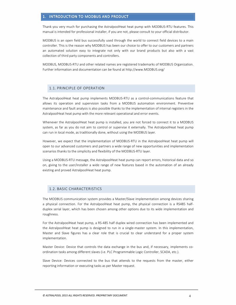
2.2.2.2. ELECTRICAL CONNECELECTRICAL CONNECELECTRICAL CONNECELECTRICAL CONNECTIONSTIONSTIONSTIONS
Image Image Image Image 1111: electrical connection: electrical connection: electrical connection: electrical connection
Note: some manufacturers assign for the RS-485 port the “A” connection as a “+”, and “B” as a “-“,
while others reverses this nomenclature. The AstralpoolHeat heat pump uses the “A” as “+”, and the
“B” as “-”. Mind this aspect when connecting to the bus devices coming from different manufacturers.
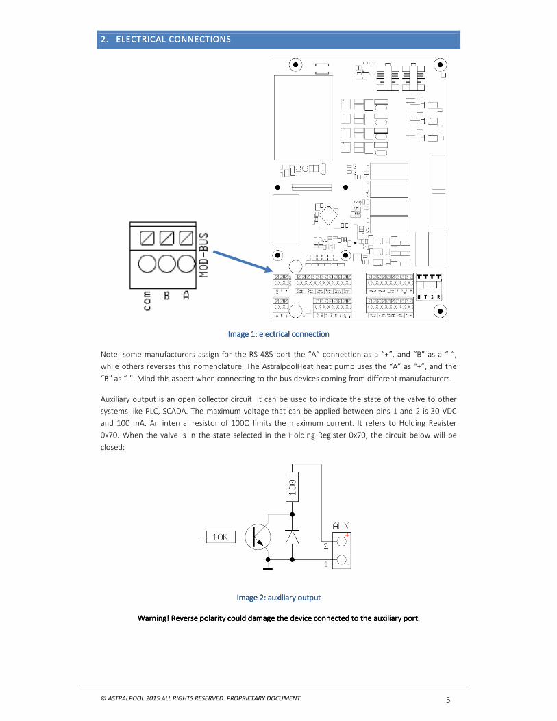
Auxiliary output is an open collector circuit. It can be used to indicate the state of the valve to other
systems like PLC, SCADA. The maximum voltage that can be applied between pins 1 and 2 is 30 VDC
and 100 mA. An internal resistor of 100Ω limits the maximum current. It refers to Holding Register
0x70. When the valve is in the state selected in the Holding Register 0x70, the circuit below will be
closed:
Image Image Image Image 2222: auxiliary output: auxiliary output: auxiliary output: auxiliary output
WarninWarninWarninWarning!g!g!g! Reverse polarity coulReverse polarity coulReverse polarity coulReverse polarity could damage the device connected tod damage the device connected tod damage the device connected tod damage the device connected to the auxiliary portthe auxiliary portthe auxiliary portthe auxiliary port....

© ASTRALPOOL 2015 ALL RIGHTS RESERVED. PROPRIETARY DOCUMENT. 6
3.3.3.3. CABLE CHARACTERISTICCABLE CHARACTERISTICCABLE CHARACTERISTICCABLE CHARACTERISTICSSSS
The recommended wiring for a MODBUS-RTU Communication is based in a linear structure, active bus
with termination at both ends. It is possible coupling and uncoupling of devices during operation
without affecting other devices. The wire shall be twisted and shielded according to EN 50 170.
The values of transmission rate supported for the device, allow maximum cable length of 1,200 m
without repeaters, or up to 10 km using repeaters, when installation is according to the standard.
For the balanced pairs used in an RS485-system, a Characteristic Impedance with a value higher than
100 Ohms may be preferred, especially for 19200 and higher baud rates.
4.4.4.4. BUS ISOLATBUS ISOLATBUS ISOLATBUS ISOLATION AND TERMINATION ION AND TERMINATION ION AND TERMINATION ION AND TERMINATION RESISTORSRESISTORSRESISTORSRESISTORS
If the communication bus is accessible for the user, it shall be double insulated. As far as in general the
accessibility of the bus to users will depend on each single installation, safety isolation has NOT been
implemented in the AstralpoolHeat heat pump physical bus layer. Moreover, for safety purposes, it is
recommended to ensure that other devices sharing this bus also implements this insulation.
Additionally, the use of bus insulated devices not only enhances the security level, furthermore
increases the equipment reliability, larger immunity to electromagnetic interference, longer life, higher
reliability, more stability over the range of temperatures.
Whenever single or multiple devices are connected sharing a bus physical connection, it is
recommended to use terminating resistors at the ends of the bus, even more when use large cable
length or high speed data rates. The terminating resistor is used to prevent an RF signal from being
reflected back from the end, causing interference. The terminating resistor must be in both ends of the
bus, connected in parallel (as shown in the image below). A typical value of this resistance is 120Ω,
0.5W. The value of the resistor must be the same in both ends. The terminating resistors are the
resistors of the Image 3: terminating resistors.
Image Image Image Image 3333: terminating resistors: terminating resistors: terminating resistors: terminating resistors
© ASTRALPOOL 2015 ALL RIGHTS RESERVED. PROPRIETARY DOCUMENT. 7
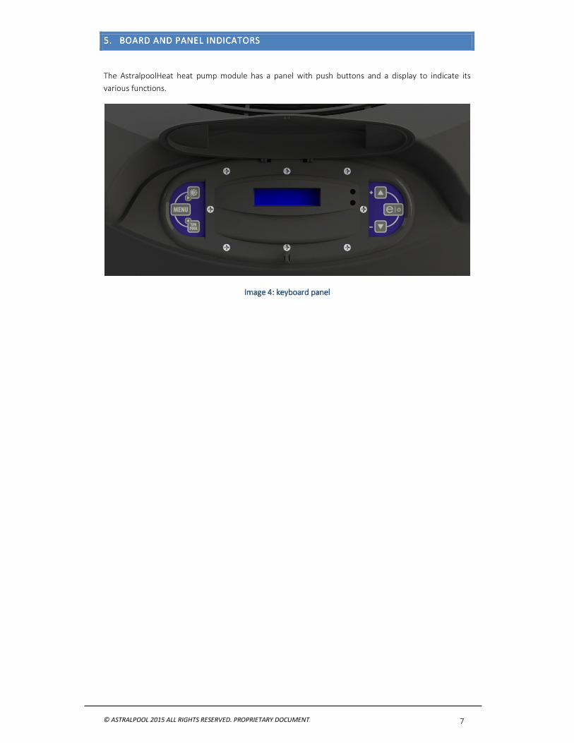
5.5.5.5. BOARD AND PANEL INDIBOARD AND PANEL INDIBOARD AND PANEL INDIBOARD AND PANEL INDICATORSCATORSCATORSCATORS
The AstralpoolHeat heat pump module has a panel with push buttons and a display to indicate its
various functions.
Image Image Image Image 4444: keyboard panel: keyboard panel: keyboard panel: keyboard panel
© ASTRALPOOL 2015 ALL RIGHTS RESERVED. PROPRIETARY DOCUMENT. 8
6.6.6.6. MODBUSMODBUSMODBUSMODBUS FUNCTIONSFUNCTIONSFUNCTIONSFUNCTIONS
6.1. FUNCTIONS SUPPORTED
Please, be carefulPlease, be carefulPlease, be carefulPlease, be careful at the possible actuationsat the possible actuationsat the possible actuationsat the possible actuations, and make sure that the function used is the correct., and make sure that the function used is the correct., and make sure that the function used is the correct., and make sure that the function used is the correct.
Functions are implemented according to the MODBUS-RTU standard described in
http://www.MODBUS.org/docs/MODBUS_Application_Protocol_V1_1b.pdf. In general registers are
unsigned 16 bit coded.
0x01 READ COILS
0x02 READ DISCRETE INPUTS
0x03 READ HOLDING REGISTERS
0x04 READ INPUT REGISTERS
0x05 WRITE SINGLE COIL
0x06 WRITE SINGLE REGISTER
0x0F WRITE MULTIPLE COILS
0x10 WRITE MULTIPLE REGISTERS
0x16 MASK WRITE REGISTER
6.2. EXCEPTION RESPONSES
Exception responses are implemented according to the MODBUS-RTU standard described in the
chapter MODBUS exception responses:
http://www.MODBUS.org/docs/MODBUS_Application_Protocol_V1_1b.pdf
The exceptions implemented are from 1 to 4 I 6.
Exceptions of type 4 are used to indicate that you are trying to use or activate a heat pump function
that cannot be used in the current configuration.
Exceptions of type 6 are used to indicate that the heat pump is in a transitory state and cannot answer
with information that is representative of the state of the pump to a request for information. The
master must repeat the operation after a few seconds.

© ASTRALPOOL 2015 ALL RIGHTS RESERVED. PROPRIETARY DOCUMENT. 9
7.7.7.7. DEVICE DESCRIPTION ADEVICE DESCRIPTION ADEVICE DESCRIPTION ADEVICE DESCRIPTION AND CND CND CND CONFIGURATIONONFIGURATIONONFIGURATIONONFIGURATION
7.1. GENERAL DESCRIPTION
In general, there is not check on the constancy of the values sent to specific registers. Therefore is the
operator responsibility to check that consistency.
In this manual, the numbers in hexadecimal have been represented with the format 0xZZ0xZZ0xZZ0xZZ, where ZZ is
the number.
The register map that governs heat pump is explained below is in the chapter 0 Basic MODBUS-rtu
Register Map.
7.2 OPERATION DIAGRAM
When the system Powers ON, the AtralPoolHeat keyborad panel will turn ON. From this point the
AstralPoolHeat will load the configuration parameters, such as setpoint temperatures, temperature
units used and so on.
Finally the AtralPoolHeat.will remain in the stop state, waiting a request to heat the water, if the
conditions in configuration parameters meet and the “on button is pushed”, the appliance will activate
the heat pump The ¡Error! No se encuentra el origen de la referencia.¡Error! No se encuentra el origen de la referencia.¡Error! No se encuentra el origen de la referencia.¡Error! No se encuentra el origen de la referencia. shows this flow.
Image Image Image Image 5555 Operation diagramOperation diagramOperation diagramOperation diagram
7.3 ADDRESS AND BAUD RATE SELECTION
7.3.1 ADDRESS SETTING
The address of the AP Heat in the bus is set through the 0x00 Holding Register.
ID_Address: Address of the AP Heat in the bus.
Factory setting: 0x06.
Suggested range: 0x06 - 0x0A.
The factory default for the AP Heat is 0x06. However you can change this value by writing this holding
register and as far as you check to not introduce collisions or conflicts with other slave’s addresses.
© ASTRALPOOL 2015 ALL RIGHTS RESERVED. PROPRIETARY DOCUMENT. 10
Example: changing the ID address from 0x06 (default) to 0x07.
Transmit Message: 06 10 00 00 00 01 02 00 07 C1 A2
Where:
06 is the slave address. (The actual ID address).
10 is the function used. Write Multiple Registers.
00 00 is the address of the first Holding Register to be written.
00 01 is the number of Holding Register to be written. 1 in this case.
02 is the number of bytes of data to be sent.
00 07 is the new ID address.
C1 A2 is the CRC.
7.3.2 BAUD RATE SELECTION
The Baud Rate selection of the serial communications with the AP Heat is set through the 0x01 Holding
Register. By default, 9600 bps and 8E1 (8 data bits, Even Parity, 1 stop bit) is implemented. However,
19200 bps, 1 and 2 stop bits with no parity are also supported. It allows us a total of six different
configurations.
The reason for supporting N2 frames is to keep the MODBUS standard requirement of sending eleven
bits per byte (1 start + 8 data + 1 parity + 1 stop). Whenever an 8N2 configuration is chosen, then 2
stop bits are introduced to keep the eleven bits per byte required by the standard.
Although 8N1 frames are also supported, keep in mind that with this selection you are not fulfilling the
MODBUS standard requirements as far as only ten bits per byte are used.
According to this, the baud rate and frame selection is completed defining the baud rate (in bauds),
number of data bits, parity and number of stop bits.
COM_Setup: Communication setup
Factory setting:Factory setting:Factory setting:Factory setting: 0000 9600, 8E19600, 8E19600, 8E19600, 8E1
Supported values: 0 9600, 8E1
1 19200, 8E1
2 9600, 8N2
3 19200, 8N2
4 9600, 8N1
5 19200 8N1
7.4 BROADCASTING
Broadcasting is not supported by the AP Heat.
© ASTRALPOOL 2015 ALL RIGHTS RESERVED. PROPRIETARY DOCUMENT. 11
8888 OPERATION MODESOPERATION MODESOPERATION MODESOPERATION MODES
8.2 BASIC OPTIONS
In this section it is assumed that a successful connection has been established with the AP Heat and
therefore, address, baud settings and watchdog behavior has been already set.
The less significant bit corresponds to the bit 0, and the most significant bit corresponds to bit 15.
In section 9 a detailed description of all records defined in the heat pump can be found. This section
provides examples of how you can use MODBUS to remotely control and monitor the operation of the
heat pump.
8.2.1 TECHNICAL CONFIGURATION OPTIONS
To complete the basic configuration of the pump, we should choose the temperature set point. As we
are going to work in POOL mode, edit the Holding Register 0x24, and enter a value in tenths of Celsius
degrees (°C) multiple of five. If we want to set a 22.5 ° C value, write the value 225.
06 06 00 24 00 E1 08 3E
Where:
06 is the slave address.
06 is the function used. Preset Single Register.
00 24 is the holding register to be written. 36 in decimal.
00 E1 is the value equivalent to 22, 5°C. 225 in decimal
08 3E is el CRC.
8.2.2 REQUEST WORD
Once we have made the heat pump configuration, we can send an order to power on the heat pump
using the Holding Register 0x21.
.bit 2..1 Sets the heat pump in one of these four operation modes:
0x00: Off
0x01: Heat
.bit 3 0: Filtration mode.
1: Comfort mode. Choose if heat pumps commands the filtration pump.
.bit 4 0: Normal
1: ECO or OEM. Choose if energy saving mode is activated.
.bits 9..8 Pool/Spa State. Equivalent to SPA/POOL keys in heat pump console.
0x00: POOL
0x01: SPA
0x10: POOL+SPA
.bit 15 1=°C, 0=°F.
Example: Turn the heat pump in heat mode, Comfort, no energy savings in POOL mode and in degrees
Celsius. So we must set the bits 1, 3 and 15.
06 06 00 21 80 0A 39 B0
Where:
06 is the slave address.
© ASTRALPOOL 2015 ALL RIGHTS RESERVED. PROPRIETARY DOCUMENT. 12
06 is the function used. Preset Single Register.
00 21 is the holding register to be written. 33 in decimal.
80 0A the order to power up the unit.
39 B0 is the CRC.
8.2.3 CHECKING STATUS
Once sent the power on command to the heat pump, it is possible via MODBUS, to monitor the
operating status of the heat pump. There are different levels of detail provided.
By reading the Input Register 0x00, we can examine the operation mode of the pump.
06 04 00 00 00 01 30 7D
Where:
06 is the slave address.
04 is the function used. Read Input Registers.
00 00 is the address of the first Input Register to be read.
00 01 is the number of records to be read.
30 7D is the CRC.
The heat pump response is:
06 04 02 80 0A ED 37
Where:
06 is the slave address.
04 is the function used. Read Input Registers.
02 is the quantity of bytes received.
80 0A is the state received:
- Bit 15 is 1: centigrade degrees.
- Bits 9...8 are 0: Pool mode.
- Bit 6 and 5 are 0: no defrost nor Standby.
- Bit 4 is 0: No energy saving mode activated.
- Bit 3 is 1: Comfort mode (heat pumps commands the filtration pump).
- Bits 2...1 are 01: Heating mode.
- Bit 0 is 0: There are no alarms.
ED 37 is the CRC.
By Input Register 0x03 we can access more detailed information about the internal state of operation
of the heat pump. For example:
06 04 00 03 00 01 C0 7D
Where:
06 is the slave address.
04 is the function used. Read Input Registers.
00 03 is the address of the first Input Register to be read.
00 01 is the number of records to be read.
C0 7D is the CRC.
The heat pump response is:
06 04 02 08 08 0A F6
© ASTRALPOOL 2015 ALL RIGHTS RESERVED. PROPRIETARY DOCUMENT. 13
Where:
06 is the slave address.
04 is the function used. Read Input Registers.
02 is the quantity of bytes received.
08 08 is the state received:
- Bit 14 is 0: There is no external stop.
- Bit 13 is 0: Heat pump connected to POOL (POOL).
- Bit 11 is 1: According to set point and water temperature, there is need to heat.
- Bit 4…1 are 0100: Compressor on.
- Bit 0 is 0: There are no alarms.
0A F6 is the CRC.
8.2.4 TEMPERATURE PROBES READINGS
The values of the readings of the temperature probes installed in the heat pump can be read by the
Input Registers 0x07 environment air temperature and 0x08, water temperature.
Specifically, to read water temperature, Input Register 0x08 is to be read.
06 04 00 08 00 01 B1 BF
Where:
06 is the slave address.
04 is the function used. Read Input Registers.
00 08 is the address of the first Input Register to be read.
00 01 is the number of records to be read.
B1 BF is the CRC.
Received response is:
06 04 02 00 C6 8C A2
Where:
06 is the slave address.
04 is the function used. Read Input Registers.
02 is the quantity of bytes received.
00 C6 is the temperature received in tenths of degrees. 198 in decimal equivalent to
19,8°C.
8C A2 is the CRC.
As temperature set point has been set to 22.5°C and the water temperature is 19,8°C, pump, as we
have seen with Input Register 0x03 is with the compressor on and heating the water.
8.2.5 DIGITAL INPUTS
The status of the digital inputs of the heat pump can be monitored using the Input Register 0x02
06 04 00 02 00 01 91 BD
Where:
06 is the slave address.

© ASTRALPOOL 2015 ALL RIGHTS RESERVED. PROPRIETARY DOCUMENT. 14
04 is the function used. Read Input Registers.
00 02 is the quantity of bytes received.
00 01 is the number of records to be read.
91 BD is the CRC.
Received response is:
06 04 02 00 77 4C D6
Where:
06 is the slave address.
04 is the function used. Read Input Registers.
02 is the quantity of bytes received.
00 77 is the estate of digital inputs of the system:
- Bit 0 is 1: water flow detected.
- Bit 1 is 1: Fan ON.
- Bit 2 is 1: Compressor ON.
- Bit 3 is 0: 4 way valve off.
- Bit 4 is 1: External stop #1 is 1
- Bit 5 is 1: External stop #2 is 1
- Bit 6 is 1: Filtration pump is on.
8C A2 is the CRC.
The read states correspond to a heat pump that is warming since the water temperature is below the
set point.
8.2.6 REAL TIME ALARMS
The state of the alarms of the heat pump can be consulted in real time and available in 0x01 Input
register. This input register contains information about the status of alarms at that exact moment of
time, activating the corresponding bits by:
.bit 0 Electrical supply alarm
.bit 1 Thermic switch alarm
.bit 2 too many attempts to reset thermal / mini pressure alarms
.bit 3 Fan alarm
.bit 4 4 way valve alarm
.bit 5 Can’t perform defrost
.bit 6 Low pressure alarm
.bit 7 High pressure alarm
.bit 8 Ambient temperature probe alarm
.bit 9 No water flow alarm
.bit 10 Water temperature probe alarm
.bit 11 Evaporator coil temperature probe alarm
.bit 15 MODBUS Watchdog alarm
For example:
06 04 00 01 00 01 61 BD
Where:
06 is the slave address.
04 is the function used. Read Input Registers.
00 01 is the address of the first Input Register to be read.
00 01 is the number of records to be read.
© ASTRALPOOL 2015 ALL RIGHTS RESERVED. PROPRIETARY DOCUMENT. 15
61 BD is the CRC.
Received response is:
06 04 02 00 82 8C 91
Where:
06 is the slave address.
04 is the function used. Read Input Registers.
02 is the quantity of bytes received.
00 82 is the status of input digital signals:
- Bit 1 is 1: Thermic switch alarm.
- Bit 7 is 1: High pressure alarm.
8C 91 is the CRC
8.2.7 ALARMS MEMORY
It is possible to view a report on the alarms produced so far. The Holding Register 0x20 contains
information about the status of alarms produced until that moment, activating the corresponding bit/s
by:
.bit 0 Electrical supply alarm
.bit 1 Thermic switch alarm
.bit 2 too many attempts to reset thermal / mini pressure alarms
.bit 3 Fan alarm
.bit 4 4 way valve alarm
.bit 5 Can’t perform defrost
.bit 6 Low pressure alarm
.bit 7 High pressure alarm
.bit 8 Ambient temperature probe alarm
.bit 9 No water flow alarm
.bit 10 Water temperature probe alarm
.bit 11 Evaporator coil temperature probe alarm
.bit 15 MODBUS Watchdog alarm
To check the status of the alarm memory, send the string:
06 03 00 20 00 01 84 77
Where:
06 is the slave address.
03 is the function used. Read Holding Registers.
00 20 is the address of the first Input Register to be read.
00 01 is the number of records to be read.
84 77 is the CRC.
Received response is:
06 03 02 00 CA 8D D3
Where:
06 is the slave address.
03 is the function used. Read Holding Registers.
© ASTRALPOOL 2015 ALL RIGHTS RESERVED. PROPRIETARY DOCUMENT. 16
02 is the quantity of bytes received.
00 CA is the state of the alarms memory:
- Bit 1 is 1: Thermic switch alarm
- Bit 3 is 1: Fan alarm
- Bit 6 is 1: Low pressure alarm
- Bit 7 is 1: High pressure alarm.
8D D3 is the CRC
The values of active bits will remain in that state even after disarming the alarm from the keyboard of
the heat pump. To reset its value, do it by directly typing into Holding Register 0x20. It is also reset
when the pump loses electrical supply.
Example:
06 06 00 20 00 00 89 B7
Where:
06 is the slave address.
06 is the function used Preset Single Register.
00 20 is the address of the Holding Register to be written.
00 00 is the value to be written
89 B7 is the CRC.
8.2.8 CHECKING COUNTERS
Using MODBUS it is also possible to check the status of operation counters of the heat pump. These
counters keep information regarding the number of operation hours of the heat pump, number of
times it has been powered off, number of times there has been a defrost, or the number of times the
different alarms have risen. These counters, which are defined in a holding record type, can be set to 0.
Example query of the number of heat pump power offs:
06 04 00 06 00 01 D0 7C
Where:
06 is the slave address.
04 is the function used. Read Input Registers.
00 06 is the address of the first Input Register to be read.
00 01 is the number of records to be read.
D0 7C is the CRC.
Received response is:
06 04 02 00 06 8C F2
Where:
06 is the slave address.
03 is the function used. Read Input Registers.
02 is the quantity of bytes received.
00 06 is the number of times the heat pump has been powered off.
8C F2 is the CRC
Example query of the number of times a security series alarm has occurred:
06 03 00 33 00 01 75 B2
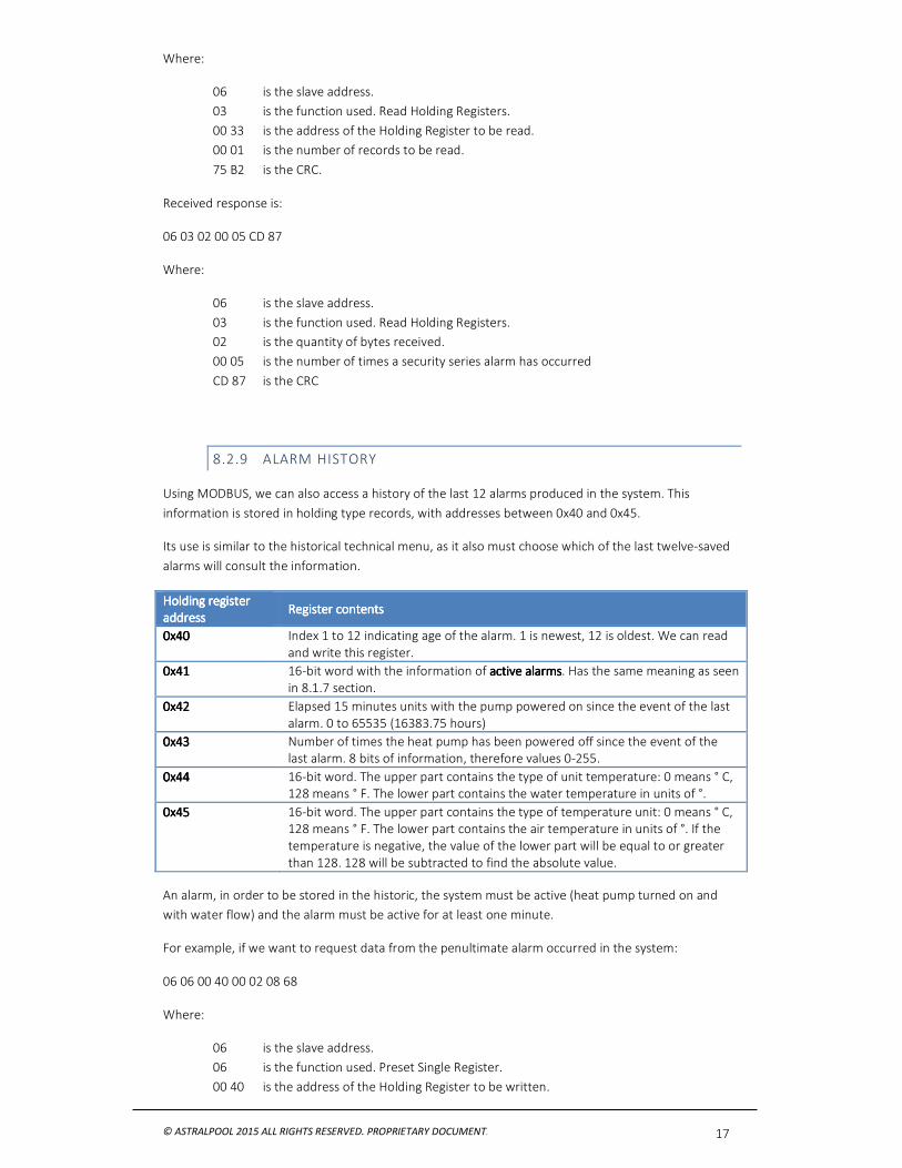
© ASTRALPOOL 2015 ALL RIGHTS RESERVED. PROPRIETARY DOCUMENT. 17
Where:
06 is the slave address.
03 is the function used. Read Holding Registers.
00 33 is the address of the Holding Register to be read.
00 01 is the number of records to be read.
75 B2 is the CRC.
Received response is:
06 03 02 00 05 CD 87
Where:
06 is the slave address.
03 is the function used. Read Holding Registers.
02 is the quantity of bytes received.
00 05 is the number of times a security series alarm has occurred
CD 87 is the CRC
8.2.9 ALARM HISTORY
Using MODBUS, we can also access a history of the last 12 alarms produced in the system. This
information is stored in holding type records, with addresses between 0x40 and 0x45.
Its use is similar to the historical technical menu, as it also must choose which of the last twelve-saved
alarms will consult the information.
Holding register Holding register Holding register Holding register
addressaddressaddressaddress RegisterRegisterRegisterRegister contentscontentscontentscontents
0x400x400x400x40 Index 1 to 12 indicating age of the alarm. 1 is newest, 12 is oldest. We can read
and write this register.
0x410x410x410x41 16-bit word with the information of active alarmsactive alarmsactive alarmsactive alarms. Has the same meaning as seen
in 8.1.7 section.
0x420x420x420x42 Elapsed 15 minutes units with the pump powered on since the event of the last
alarm. 0 to 65535 (16383.75 hours)
0x430x430x430x43 Number of times the heat pump has been powered off since the event of the
last alarm. 8 bits of information, therefore values 0-255.
0x440x440x440x44 16-bit word. The upper part contains the type of unit temperature: 0 means ° C,
128 means ° F. The lower part contains the water temperature in units of °.
0x450x450x450x45 16-bit word. The upper part contains the type of temperature unit: 0 means ° C,
128 means ° F. The lower part contains the air temperature in units of °. If the
temperature is negative, the value of the lower part will be equal to or greater
than 128. 128 will be subtracted to find the absolute value.
An alarm, in order to be stored in the historic, the system must be active (heat pump turned on and
with water flow) and the alarm must be active for at least one minute.
For example, if we want to request data from the penultimate alarm occurred in the system:
06 06 00 40 00 02 08 68
Where:
06 is the slave address.
06 is the function used. Preset Single Register.
00 40 is the address of the Holding Register to be written.
© ASTRALPOOL 2015 ALL RIGHTS RESERVED. PROPRIETARY DOCUMENT. 18
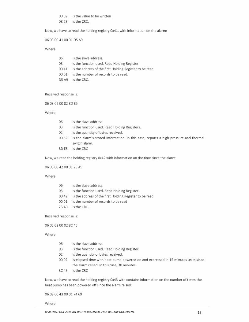
00 02 is the value to be written
08 68 is the CRC.
Now, we have to read the holding registry 0x41, with information on the alarm:
06 03 00 41 00 01 D5 A9
Where:
06 is the slave address.
03 is the function used. Read Holding Register.
00 41 is the address of the first Holding Register to be read.
00 01 is the number of records to be read.
D5 A9 is the CRC.
Received response is:
06 03 02 00 82 8D E5
Where:
06 is the slave address.
03 is the function used. Read Holding Registers.
02 is the quantity of bytes received.
00 82 is the alarm’s stored information. In this case, reports a high pressure and thermal
switch alarm.
8D E5 is the CRC
Now, we read the holding registry 0x42 with information on the time since the alarm:
06 03 00 42 00 01 25 A9
Where:
06 is the slave address.
03 is the function used. Read Holding Register.
00 42 is the address of the first Holding Register to be read.
00 01 is the number of records to be read
25 A9 is the CRC.
Received response is:
06 03 02 00 02 8C 45
Where:
06 is the slave address.
03 is the function used. Read Holding Register.
02 is the quantity of bytes received.
00 02 is elapsed time with heat pump powered on and expressed in 15 minutes units since
the alarm raised. In this case, 30 minutes
8C 45 is the CRC
Now, we have to read the holding registry 0x43 with contains information on the number of times the
heat pump has been powered off since the alarm raised:
06 03 00 43 00 01 74 69
Where:
© ASTRALPOOL 2015 ALL RIGHTS RESERVED. PROPRIETARY DOCUMENT. 19
06 is the slave address.
03 is the function used. Read Holding Register.
00 43 is the address of the first Holding Register to be read.
00 01 is the number of records to be read
74 69 is the CRC.
Received response is:
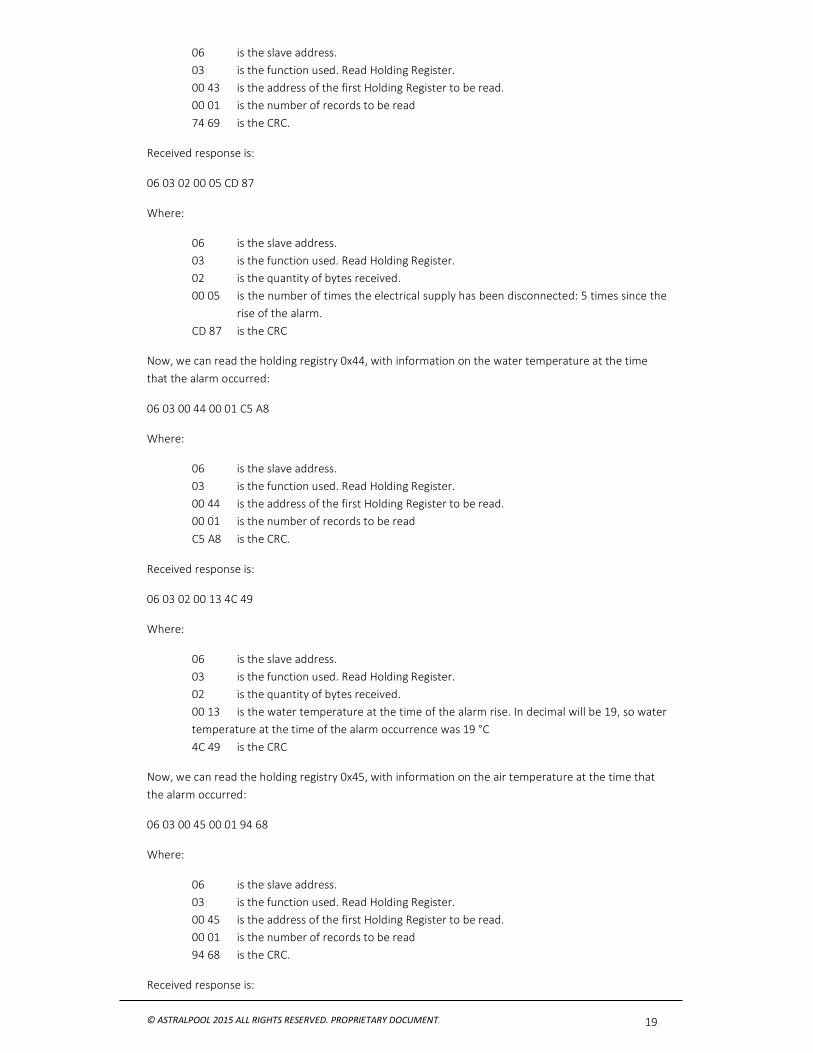
06 03 02 00 05 CD 87
Where:
06 is the slave address.
03 is the function used. Read Holding Register.
02 is the quantity of bytes received.
00 05 is the number of times the electrical supply has been disconnected: 5 times since the
rise of the alarm.
CD 87 is the CRC
Now, we can read the holding registry 0x44, with information on the water temperature at the time
that the alarm occurred:
06 03 00 44 00 01 C5 A8
Where:
06 is the slave address.
03 is the function used. Read Holding Register.
00 44 is the address of the first Holding Register to be read.
00 01 is the number of records to be read
C5 A8 is the CRC.
Received response is:
06 03 02 00 13 4C 49
Where:
06 is the slave address.
03 is the function used. Read Holding Register.
02 is the quantity of bytes received.
00 13 is the water temperature at the time of the alarm rise. In decimal will be 19, so water
temperature at the time of the alarm occurrence was 19 °C
4C 49 is the CRC
Now, we can read the holding registry 0x45, with information on the air temperature at the time that
the alarm occurred:
06 03 00 45 00 01 94 68
Where:
06 is the slave address.
03 is the function used. Read Holding Register.
00 45 is the address of the first Holding Register to be read.
00 01 is the number of records to be read
94 68 is the CRC.
Received response is:

© ASTRALPOOL 2015 ALL RIGHTS RESERVED. PROPRIETARY DOCUMENT. 20
06 03 02 00 13 4C 49
Where:
06 is the slave address.
03 is the function used. Read Holding Register.
02 is the quantity of bytes received.
00 13 is the air temperature at the time of the alarm rise. In decimal will be 19, so air
temperature at the time of the alarm occurrence was 19 °C.
4C 49 is the CRC
© ASTRALPOOL 2015 ALL RIGHTS RESERVED. PROPRIETARY DOCUMENT. 21
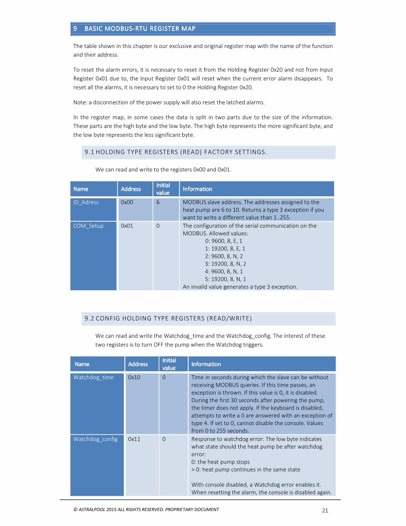
9999 BASIC BASIC BASIC BASIC MODBUSMODBUSMODBUSMODBUS----RTU REGISTER MAPRTU REGISTER MAPRTU REGISTER MAPRTU REGISTER MAP
The table shown in this chapter is our exclusive and original register map with the name of the function
and their address.
To reset the alarm errors, it is necessary to reset it from the Holding Register 0x20 and not from Input
Register 0x01 due to, the Input Register 0x01 will reset when the current error alarm disappears. To
reset all the alarms, it is necessary to set to 0 the Holding Register 0x20.
Note: a disconnection of the power supply will also reset the latched alarms.
In the register map, in some cases the data is split in two parts due to the size of the information.
These parts are the high byte and the low byte. The high byte represents the more significant byte, and
the low byte represents the less significant byte.
9.1 HOLDING TYPE REGISTERS (READ) FACTORY SETTINGS.
We can read and write to the registers 0x00 and 0x01.
NameNameNameName AddressAddressAddressAddress Initial Initial Initial Initial
valuevaluevaluevalue InformationInformationInformationInformation
ID_Adress 0x00 6 MODBUS slave address. The addresses assigned to the
heat pump are 6 to 10. Returns a type 3 exception if you
want to write a different value than 1..255.
COM_Setup 0x01 0 The configuration of the serial communication on the
MODBUS. Allowed values:
0: 9600, 8, E, 1
1: 19200, 8, E, 1
2: 9600, 8, N, 2
3: 19200, 8, N, 2
4: 9600, 8, N, 1
5: 19200, 8, N, 1
An invalid value generates a type 3 exception.
9.2 CONFIG HOLDING TYPE REGISTERS (READ/WRITE)
We can read and write the Watchdog_time and the Watchdog_config. The interest of these
two registers is to turn OFF the pump when the Watchdog triggers.
NameNameNameName AddressAddressAddressAddress Initial Initial Initial Initial
valuevaluevaluevalue InformationInformationInformationInformation
Watchdog_time 0x10 0 Time in seconds during which the slave can be without
receiving MODBUS queries. If this time passes, an
exception is thrown. If this value is 0, it is disabled.
During the first 30 seconds after powering the pump,
the timer does not apply. If the keyboard is disabled,
attempts to write a 0 are answered with an exception of
type 4. If set to 0, cannot disable the console. Values
from 0 to 255 seconds.
Watchdog_config 0x11 0 Response to watchdog error: The low byte indicates
what state should the heat pump be after watchdog
error:
0: the heat pump stops
> 0: heat pump continues in the same state
With console disabled, a Watchdog error enables it.
When resetting the alarm, the console is disabled again.

© ASTRALPOOL 2015 ALL RIGHTS RESERVED. PROPRIETARY DOCUMENT. 22
9.3. ALARMS & OPERATION HOLDING REGISTERS (READ/WRITE)
NameNameNameName AddressAddressAddressAddress Initial Initial Initial Initial
valuevaluevaluevalue InformationInformationInformationInformation
Alarm historic 0x20 0 Contains information on alarms that have been activated
at some point. Must be reset by writing a 0 from the
MODBUS or removing electrical supply. Each bit has a
meaning associated with a type of alarm.
BitBitBitBit AlarmAlarmAlarmAlarm
0000 Electrical supply alarm.
1111 Thermal switch alarm.
2222 If security serie (hight and low presure & termal
switches) fails, retry up to three times daily.
3333 Fan alarm.
4444 4 way valve error.
5555 Cannot perform defrost process.
6666 Low pressure switch alarm.
7777 High pressure switch alarm.
8888 Ambient air temperature probe error.
9999 Water flow error.
10101010 Water temperature probe error.
11111111 Evaporator temperature probe error.
12121212
13131313
14141414
15151515 Watchdog de MODBUS. Exceeded the limit time
without receiving a MODBUS string.
Request_Word 0x21 8 It is the register that allows us to turn on the pump in any
possible operation mode. By default, the pump is off in
Comfort mode.
bit 0 Not used.
bits 2..1 00 Heat pump off
01 Heat
bit 3 0: Filtration mode
1: Comfort mode. Returns a type 4 exception if
comfort mode is not enabled.
bit 4 0: No energy saving mode activated
1: Energy saving mode activated according bits
11..10 of 0x12 register
The first two bits (8 & 9) of the high byte of the register
allow us to choose whether we work on pool, SPA or both
(Pool + SPA).
00: Pool
01: SPA
10: SPA+POOL
Bit 15 1: Units ° Celsius.
0: Units ° Fahrenheit
Set Point
temperature
(POOL)
0x24 250 o
77
Temperature set point for pool water. If in ° C, the units
are tenths of a degree in multiples of 5. 120-400 tenths of
° C range. If in ° F, write value directly in ° Fahrenheit.
Invalid values return a type 4 exception.
© ASTRALPOOL 2015 ALL RIGHTS RESERVED. PROPRIETARY DOCUMENT. 23
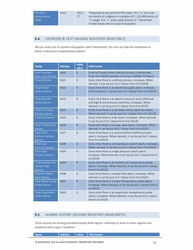
Set Point
temperature
(SPA)
0x25 250 o
77
Temperature set point for SPA water. If in ° C, the units
are tenths of a degree in multiples of 5. 120-400 tenths of
° C range. If in ° F, write value directly in ° Fahrenheit.
Invalid values return a type 4 exception.
9.4.9.4.9.4.9.4. COUNTERS & TEST HOLDING REGISTERS (READ ONLY)
We can read a list of counters that gather useful information, this info can help the installation to
better understand a hypothetical problem.
NameNameNameName AddressAddressAddressAddress Initial Initial Initial Initial
valuevaluevaluevalue InformationInformationInformationInformation
Hour Quarters
Since Last Defrost
0x30 0 Is set to 0 every time a defrost process is performed.
From 0 to 65535 quarters of an hour (16383.75 hours).
Total Defrosts 0x31 0 Every time there is a defrost process, increases. When
desired, it can be put to 0. Values from 0 to 65535.
Total Power
Failure Alarms
0x32 0 Every time there is an electrical supply alarm, increases.
When desired, it can be put to 0. Values from 0 to 65535.
Total Security
Series Alarms
0x33 0 Every time there is an alarm in security series (thermal
and high & low pressure switches), increases. When
desired, it can be put to 0. Values from 0 to 65535.
Total Too Many
Retries Alarms
0x34 0 Every time there is a too many retries alarm increases.
When desired, it can be put to 0. Values from 0 to 65535.
Total Fan Alarms 0x35 0 Every time there is a fan alarm, increases. When desired,
it can be put to 0. Values from 0 to 65535.
Total 4 Way Valve
Alarms
0x36 0 Every time there is a 4 way valve alarm, increases. When
desired, it can be put to 0. Values from 0 to 65535.
Total Can’t
Perform Defrost
Alarms
0x37 0 Every time there is a cannot perform defrost process
alarm, increases. When desired, it can be put to 0. Values
from 0 to 65535.
Total Low
Pressure Alarms
0x38 0 Every time there is a low pressure switch alarm, increases.
When desired, it can be put to 0. Values from 0 to 65535.
Total High
Pressure Alarms
0x39 0 Every time there is a high pressure switch alarm,
increases. When desired, it can be put to 0. Values from 0
to 65535.
Total Ambient Air
Temp Probe
Alarms
0x3A 0 Every time there is an ambient air temperature probe
alarm, increases. When desired, it can be put to 0. Values
from 0 to 65535.
Total No Water
Flow Alarms
0x3B 0 Every time there is a water flow alarm, increases. When
desired, it can be put to 0. Values from 0 to 65535.
Total Water Temp
Probe Alarms
0x3C 0 Every time there is a water temperature probe alarm,
increases. When desired, it can be put to 0. Values from 0
to 65535.
Total Evaporator
Probe Alarms
0x3D 0 Every time there is an evaporator temperature probe
alarm, increases. When desired, it can be put to 0. Values
from 0 to 65535.
9.5.9.5.9.5.9.5. ALARMS HISTORY HOLDING REGISTERS (READ/WRITE)
These records are writing prohibited except 0x40 register. Attempts to write to other registers are
answered with a type 2 exception.
NameNameNameName AddressAddressAddressAddress Initial Initial Initial Initial InformationInformationInformationInformation
© ASTRALPOOL 2015 ALL RIGHTS RESERVED. PROPRIETARY DOCUMENT. 24
valuevaluevaluevalue
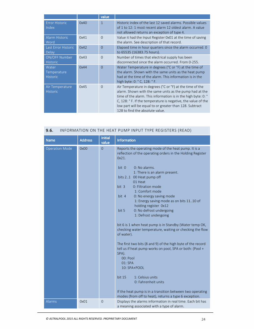
Error Historic
Index
0x40 1 Historic index of the last 12 saved alarms. Possible values
of 1 to 12: 1 most recent alarm 12 oldest alarm. A value
not allowed returns an exception of type 4.
Alarm Historic
Word
0x41 0 Value it had the Input Register 0x01 at the time of saving
the alarm. See description of that record.
Last Error Historic
Delay
0x42 0 Elapsed time in hour quarters since the alarm occurred. 0
to 65535 (16383.75 hours).
ON/OFF Number
Historic
0x43 0 Number of times that electrical supply has been
disconnected since the alarm occurred. From 0-255.
Water
Temperature
Historic
0x44 0 Water Temperature in degrees (°C or °F) at the time of
the alarm. Shown with the same units as the heat pump
had at the time of the alarm. This information is in the
high byte: 0: ° C, 128: ° F.
Air Temperature
Historic
0x45 0 Air Temperature in degrees (°C or °F) at the time of the
alarm. Shown with the same units as the pump had at the
time of the alarm. This information is in the high byte: 0: °
C, 128: ° F. If the temperature is negative, the value of the
low part will be equal to or greater than 128. Subtract
128 to find the absolute value.
9.6.9.6.9.6.9.6. INFORMATION ON THE HEAT PUMP INPUT TYPE REGISTERS (READ)
NameNameNameName AddressAddressAddressAddress Initial Initial Initial Initial
valuevaluevaluevalue InformationInformationInformationInformation
Operation Mode 0x00 0 Reports the operating mode of the heat pump. It is a
reflection of the operating orders in the Holding Register
0x21.
bit 0 0: No alarms.
1: There is an alarm present.
bits 2..1 00 Heat pump off
01 Heat
bit 3 0: Filtration mode
1: Comfort mode
bit 4 0: No energy saving mode
1: Energy saving mode as on bits 11..10 of
holding register 0x12
bit 5 0: No defrost undergoing
1: Defrost undergoing
bit 6 is 1 when heat pump is in Standby (Water temp OK,
checking water temperature, waiting or checking the flow
of water).
The first two bits (8 and 9) of the high byte of the record
tell us if heat pump works on pool, SPA or both: (Pool +
SPA).
00: Pool
01: SPA
10: SPA+POOL
bit 15 1: Celsius units
0: Fahrenheit units
If the heat pump is in a transition between two operating
modes (from off to heat), returns a type 6 exception.
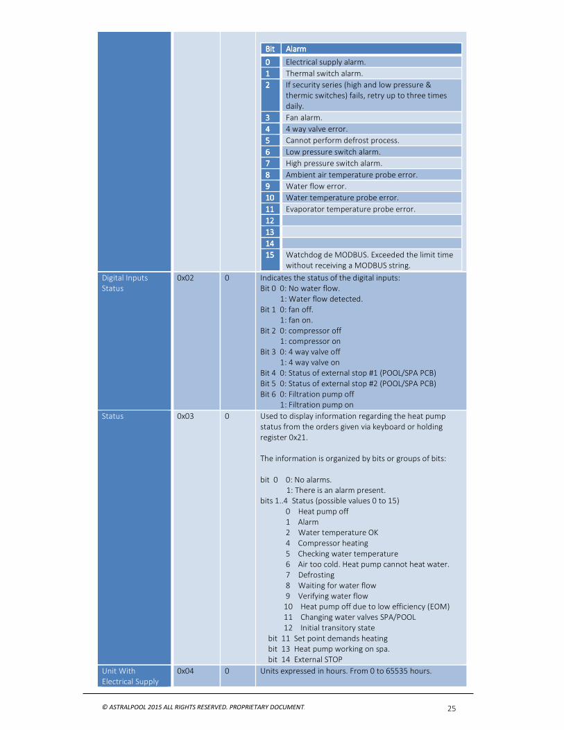
Alarms 0x01 0 Displays the alarms information in real time. Each bit has
a meaning associated with a type of alarm.
© ASTRALPOOL 2015 ALL RIGHTS RESERVED. PROPRIETARY DOCUMENT. 25
BitBitBitBit AlarmAlarmAlarmAlarm
0000 Electrical supply alarm.
1111 Thermal switch alarm.
2222 If security series (high and low pressure &
thermic switches) fails, retry up to three times
daily.
3333 Fan alarm.
4444 4 way valve error.
5555 Cannot perform defrost process.
6666 Low pressure switch alarm.
7777 High pressure switch alarm.
8888 Ambient air temperature probe error.
9999 Water flow error.
10101010 Water temperature probe error.
11111111 Evaporator temperature probe error.
12121212
13131313
14141414
15151515 Watchdog de MODBUS. Exceeded the limit time
without receiving a MODBUS string.
Digital Inputs
Status
0x02 0 Indicates the status of the digital inputs:
Bit 0 0: No water flow.
1: Water flow detected.
Bit 1 0: fan off.
1: fan on.
Bit 2 0: compressor off
1: compressor on
Bit 3 0: 4 way valve off
1: 4 way valve on
Bit 4 0: Status of external stop #1 (POOL/SPA PCB)
Bit 5 0: Status of external stop #2 (POOL/SPA PCB)
Bit 6 0: Filtration pump off
1: Filtration pump on
Status 0x03 0 Used to display information regarding the heat pump
status from the orders given via keyboard or holding
register 0x21.
The information is organized by bits or groups of bits:
bit 0 0: No alarms.
1: There is an alarm present.
bits 1..4 Status (possible values 0 to 15)
0 Heat pump off
1 Alarm
2 Water temperature OK
4 Compressor heating
5 Checking water temperature
6 Air too cold. Heat pump cannot heat water.
7 Defrosting
8 Waiting for water flow
9 Verifying water flow
10 Heat pump off due to low efficiency (EOM)
11 Changing water valves SPA/POOL
12 Initial transitory state
bit 11 Set point demands heating
bit 13 Heat pump working on spa.
bit 14 External STOP
Unit With
Electrical Supply
0x04 0 Units expressed in hours. From 0 to 65535 hours.
© ASTRALPOOL 2015 ALL RIGHTS RESERVED. PROPRIETARY DOCUMENT. 26
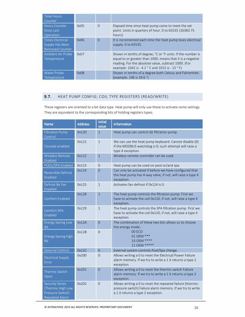
Total Hours
Counter
Hours Counter
Since Last
Operation
0x05 0 Elapsed time since heat pump came to meet the set
point. Units in quarters of hour. 0 to 65535 (16383.75
hours)
Times Electrical
Supply Has Been
Removed Counter
0x06 0 It is incremented each time the heat pump loses electrical
supply. 0 to 65535.
Ambient Air Probe
Temperature
0x07 Shown in tenths of degree, °C or °F units. If the number is
equal to or greater than 1000, means that it is a negative
reading. For the absolute value, subtract 1000. (For
example: 1042 is - 4.2 ° C and 1015 is - 15 ° F)
Water Probe
Temperature
0x08 Shown in tenths of a degree both Celsius and Fahrenheit.
(example: 196 is 19.6 °)
9.7.9.7.9.7.9.7. HEAT PUMP CONFIG; COIL TYPE REGISTERS (READ/WRITE)
These registers are oriented to a bit data type. Heat pump will only use these to activate some settings.
They are equivalent to the corresponding bits of holding registers types.
NaNaNaNamemememe AddressAddressAddressAddress Initial Initial Initial Initial
valuevaluevaluevalue InformationInformationInformationInformation
Filtration Pump
Control
0x120 1 Heat pump can control de filtration pump.
Console enabled
0x121 1 We can use the heat pump keyboard. Cannot disable (0)
if the MODBUS watchdog is 0; such attempt will raise a
type 4 exception.
Wireless Remote
Enabled
0x122 1 Wireless remote controller can be used.
POOL/SPA Enabled 0x123 0 Heat pump can be used on pool or/and spa.
Reversible Defrost
Enabled
0x124 0 Can only be activated if before we have configured that
the heat pump has 4-way valve, if not, will raise a type 4
exception.
Defrost By Fan
Enabled
0x125 1 Activates fan defrost if 0x124 is 0.
Comfort Enabled
0x128 1 The heat pump controls the filtration pump. First we
have to activate the coil 0x120, if not, will raise a type 4
exception.
Comfort SPA
Enabled
0x129 1 The heat pump controls the SPA filtration pump. First we
have to activate the coil 0x120, if not, will raise a type 4
exception.
Energy Saving Low
Bit
0x12A 0 The combination of these two bits allows us to choose
the energy mode:
00 ECO
01 OEM ***
10 OEM ****
11 OEM *****
Energy Saving High
Bit
0x12B 0
External Control 0x12C 0 External system controls Pool/Spa change.
Electrical Supply
Error
0x200 0 Allows writing a 0 to reset the Electrical Power Failure
alarm memory. If we try to write a 1 it returns a type 2
exception.
Thermic Switch
Open
0x201 0 Allows writing a 0 to reset the thermic switch Failure
alarm memory. If we try to write a 1 it returns a type 2
exception.
Security Series
(Thermic-High Low
Pressure Switch)
Repeated Alarm
0x202 0 Allows writing a 0 to reset the repeated failure (thermic-
pressure switch) Failure alarm memory. If we try to write
a 1 it returns a type 2 exception.
© ASTRALPOOL 2015 ALL RIGHTS RESERVED. PROPRIETARY DOCUMENT. 27
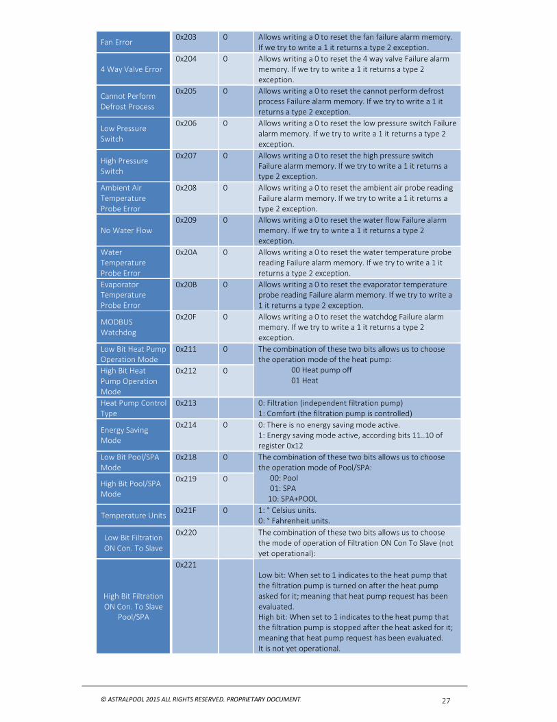
Fan Error 0x203 0 Allows writing a 0 to reset the fan failure alarm memory.
If we try to write a 1 it returns a type 2 exception.
4 Way Valve Error
0x204 0 Allows writing a 0 to reset the 4 way valve Failure alarm
memory. If we try to write a 1 it returns a type 2
exception.
Cannot Perform
Defrost Process
0x205 0 Allows writing a 0 to reset the cannot perform defrost
process Failure alarm memory. If we try to write a 1 it
returns a type 2 exception.
Low Pressure
Switch
0x206 0 Allows writing a 0 to reset the low pressure switch Failure
alarm memory. If we try to write a 1 it returns a type 2
exception.
High Pressure
Switch
0x207 0 Allows writing a 0 to reset the high pressure switch
Failure alarm memory. If we try to write a 1 it returns a
type 2 exception.
Ambient Air
Temperature
Probe Error
0x208 0 Allows writing a 0 to reset the ambient air probe reading
Failure alarm memory. If we try to write a 1 it returns a
type 2 exception.
No Water Flow
0x209 0 Allows writing a 0 to reset the water flow Failure alarm
memory. If we try to write a 1 it returns a type 2
exception.
Water
Temperature
Probe Error
0x20A 0 Allows writing a 0 to reset the water temperature probe
reading Failure alarm memory. If we try to write a 1 it
returns a type 2 exception.
Evaporator
Temperature
Probe Error
0x20B 0 Allows writing a 0 to reset the evaporator temperature
probe reading Failure alarm memory. If we try to write a
1 it returns a type 2 exception.
MODBUS
Watchdog
0x20F 0 Allows writing a 0 to reset the watchdog Failure alarm
memory. If we try to write a 1 it returns a type 2
exception.
Low Bit Heat Pump
Operation Mode
0x211 0 The combination of these two bits allows us to choose
the operation mode of the heat pump:
00 Heat pump off
01 Heat
High Bit Heat
Pump Operation
Mode
0x212 0
Heat Pump Control
Type
0x213 0: Filtration (independent filtration pump)
1: Comfort (the filtration pump is controlled)
Energy Saving
Mode
0x214 0 0: There is no energy saving mode active.
1: Energy saving mode active, according bits 11..10 of
register 0x12
Low Bit Pool/SPA
Mode
0x218 0 The combination of these two bits allows us to choose
the operation mode of Pool/SPA:
00: Pool
01: SPA
10: SPA+POOL
High Bit Pool/SPA
Mode
0x219 0
Temperature Units 0x21F 0 1: ° Celsius units.
0: ° Fahrenheit units.
Low Bit Filtration
ON Con. To Slave
0x220 The combination of these two bits allows us to choose
the mode of operation of Filtration ON Con To Slave (not
yet operational):
High Bit Filtration
ON Con. To Slave
Pool/SPA
0x221
Low bit: When set to 1 indicates to the heat pump that
the filtration pump is turned on after the heat pump
asked for it; meaning that heat pump request has been
evaluated.
High bit: When set to 1 indicates to the heat pump that
the filtration pump is stopped after the heat asked for it;
meaning that heat pump request has been evaluated.
It is not yet operational.
© ASTRALPOOL 2015 ALL RIGHTS RESERVED. PROPRIETARY DOCUMENT. 28
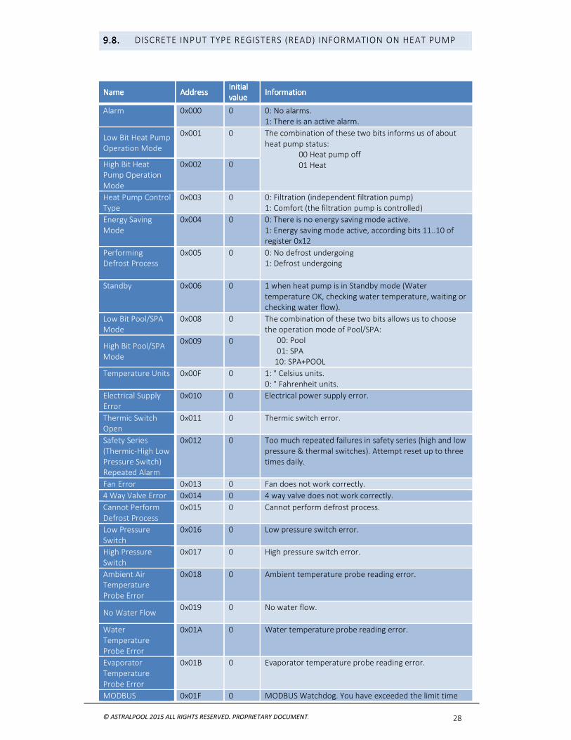
9.8.9.8.9.8.9.8. DISCRETE INPUT TYPE REGISTERS (READ) INFORMATION ON HEAT PUMP
NameNameNameName AddressAddressAddressAddress InitiaInitiaInitiaInitial l l l
valuevaluevaluevalue InformationInformationInformationInformation
Alarm 0x000 0 0: No alarms.
1: There is an active alarm.
Low Bit Heat Pump
Operation Mode
0x001 0 The combination of these two bits informs us of about
heat pump status:
00 Heat pump off
01 Heat
High Bit Heat
Pump Operation
Mode
0x002 0
Heat Pump Control
Type
0x003 0 0: Filtration (independent filtration pump)
1: Comfort (the filtration pump is controlled)
Energy Saving
Mode
0x004 0 0: There is no energy saving mode active.
1: Energy saving mode active, according bits 11..10 of
register 0x12
Performing
Defrost Process
0x005 0 0: No defrost undergoing
1: Defrost undergoing
Standby 0x006 0 1 when heat pump is in Standby mode (Water
temperature OK, checking water temperature, waiting or
checking water flow).
Low Bit Pool/SPA
Mode
0x008 0 The combination of these two bits allows us to choose
the operation mode of Pool/SPA:
00: Pool
01: SPA
10: SPA+POOL
High Bit Pool/SPA
Mode
0x009 0
Temperature Units 0x00F 0 1: ° Celsius units.
0: ° Fahrenheit units.
Electrical Supply
Error
0x010 0 Electrical power supply error.
Thermic Switch
Open
0x011 0 Thermic switch error.
Safety Series
(Thermic-High Low
Pressure Switch)
Repeated Alarm
0x012 0 Too much repeated failures in safety series (high and low
pressure & thermal switches). Attempt reset up to three
times daily.
Fan Error 0x013 0 Fan does not work correctly.
4 Way Valve Error 0x014 0 4 way valve does not work correctly.
Cannot Perform
Defrost Process
0x015 0 Cannot perform defrost process.
Low Pressure
Switch
0x016 0 Low pressure switch error.
High Pressure
Switch
0x017 0 High pressure switch error.
Ambient Air
Temperature
Probe Error
0x018 0 Ambient temperature probe reading error.
No Water Flow 0x019 0 No water flow.
Water
Temperature
Probe Error
0x01A 0 Water temperature probe reading error.
Evaporator
Temperature
Probe Error
0x01B 0 Evaporator temperature probe reading error.
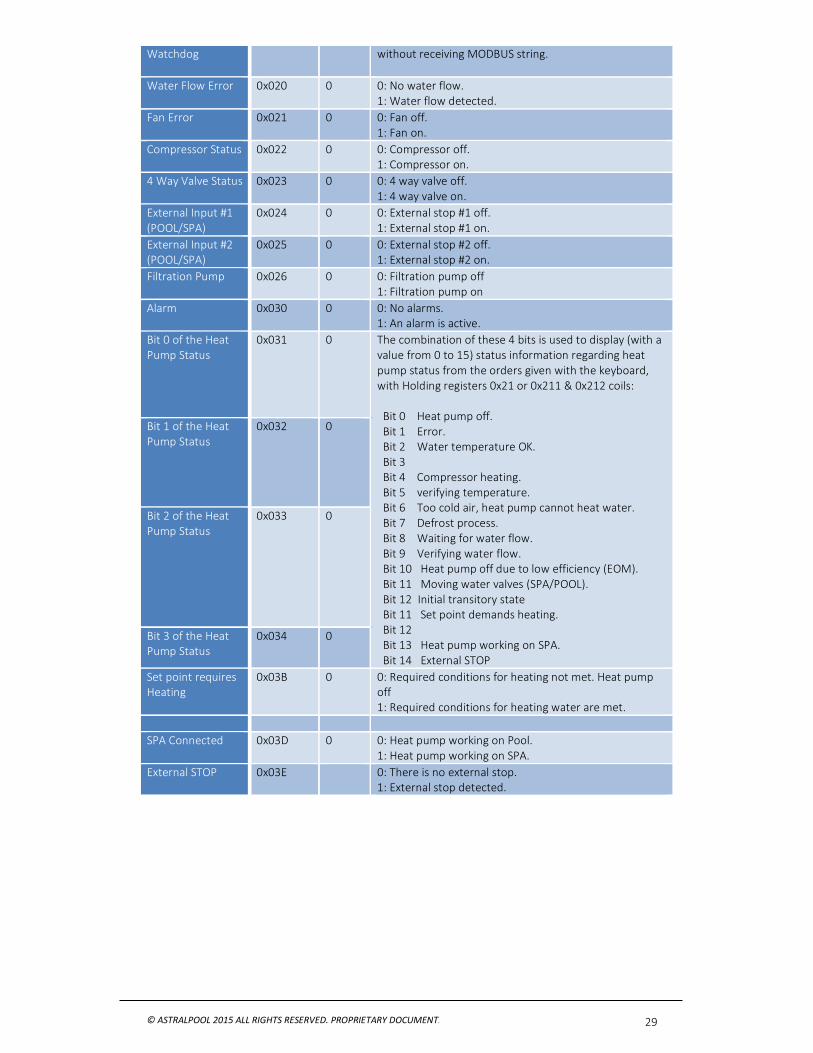
MODBUS 0x01F 0 MODBUS Watchdog. You have exceeded the limit time
© ASTRALPOOL 2015 ALL RIGHTS RESERVED. PROPRIETARY DOCUMENT. 29
Watchdog without receiving MODBUS string.
Water Flow Error 0x020 0 0: No water flow.
1: Water flow detected.
Fan Error 0x021 0 0: Fan off.
1: Fan on.
Compressor Status 0x022 0 0: Compressor off.
1: Compressor on.
4 Way Valve Status 0x023 0 0: 4 way valve off.
1: 4 way valve on.
External Input #1
(POOL/SPA)
0x024 0 0: External stop #1 off.
1: External stop #1 on.
External Input #2
(POOL/SPA)
0x025 0 0: External stop #2 off.
1: External stop #2 on.
Filtration Pump 0x026 0 0: Filtration pump off
1: Filtration pump on
Alarm 0x030 0 0: No alarms.
1: An alarm is active.
Bit 0 of the Heat
Pump Status
0x031 0 The combination of these 4 bits is used to display (with a
value from 0 to 15) status information regarding heat
pump status from the orders given with the keyboard,
with Holding registers 0x21 or 0x211 & 0x212 coils:
Bit 0 Heat pump off.
Bit 1 Error.
Bit 2 Water temperature OK.
Bit 3
Bit 4 Compressor heating.
Bit 5 verifying temperature.
Bit 6 Too cold air, heat pump cannot heat water.
Bit 7 Defrost process.
Bit 8 Waiting for water flow.
Bit 9 Verifying water flow.
Bit 10 Heat pump off due to low efficiency (EOM).
Bit 11 Moving water valves (SPA/POOL).
Bit 12 Initial transitory state
Bit 11 Set point demands heating.
Bit 12
Bit 13 Heat pump working on SPA.
Bit 14 External STOP
Bit 1 of the Heat
Pump Status
0x032 0
Bit 2 of the Heat
Pump Status
0x033 0
Bit 3 of the Heat
Pump Status
0x034 0
Set point requires
Heating
0x03B 0 0: Required conditions for heating not met. Heat pump
off
1: Required conditions for heating water are met.
SPA Connected 0x03D 0 0: Heat pump working on Pool.
1: Heat pump working on SPA.
External STOP 0x03E 0: There is no external stop.
1: External stop detected.

© ASTRALPOOL 2015 ALL RIGHTS RESERVED. PROPRIETARY DOCUMENT. 30
10.10.10.10. PRODUCT PRODUCT PRODUCT PRODUCT REVISIONREVISIONREVISIONREVISION
Manual v.0.5 : All the information of this manual, describes the behavior of the Hardware Version
9130, and Software Version 3.14.
Changelog:


WE RESERVE THE RIGHT TO CHANGE ALL OR PART OF THE FEATURES OF THE ARTICLES OR CONTENTS OF THIS DOCUMENT, WITHOUT PRIOR NOTICE
NOS RESERVAMOS EL DERECHO DE CAMBIAR TOTAL O PARCIALMENTE LAS CARACTERÍSTICAS DE NUESTROS ARTÍCULOS O CONTENIDO DE ESTE DOCUMENTO SIN PREVIO AVISO.
NOUS NOUS RÉSERVONS LE DROIT DE MODIFIER EN TOUT OU EN PARTIE LES CARACTÉRISTIQUES DE NOS ARTICLES OU LE CONTENU DE CE DOCUMENT SANS AVIS
DE WIR BEHALTEN UNS DAS RECHT VOR, DIE CHARAKTERISTIKA UNSERER PRODUKTE ODER DEN INHALT DIESES DOKUMENTS OHNE VORHERIGE ANKÜNDIGUNG VOLLSTÄNDIG ODER TEILWEISE ZU ÄNDERN.
CI RISERVIAMO IL DIRITTO DI MODIFICARE IN TUTTO O IN PARTE LE CARATTERISTICHE DEI NOSTRI ARTICOLI O CONTENUTO DI QUESTO DOCUMENTO SENZA PREAVVISO.
WIJ BEHOUDEN ONS HET RECHT VOOR OM DE KENMERKEN VAN DE ARTIKELS OF DE INHOUD VAN DIT DOCUMENT ZONDER VOORAF GAANDE KENNISGEVING GEHEEL OF GEDEELTELIJK TE WIJZIGEN.
RESERVAMO-NOS O DIREITO DE ALTERAR TOTAL OU PARCIALMENTE AS CARACTERÍSTICAS DOS NOSSOS ARTIGOS OU O CONTEÚDO DESTE DOCUMENTO SEM AVISO PRÉVIO.