Embed Size (px)
Citation preview

INSTRUCTION MANUALOPERATION MICROSCOPE
OMS-800

INTRODUCTION
Thank you for purchasing the TOPCON OMS-800 Operation Microscope.
This product is an operation microscope for operations, treatment or observation.
This product is classified in five types according to the difference in the combination of themicroscope unit with the base unit. Each of five types is classified into two different types: onetype is equipped with a beam splitter of the fixed spectral ratio and the other with achangeable beam splitter which can alternate two spectral ratios to each other.
• OFFISS : The microscope unit with the front lens is combined with the inverter and thebase unit with the electromagnetic lock and the rough focusing unit.
• OFFISS Lite : The microscope unit with the front lens is combined with the inverter and thebase unit with the electromagnetic lock and without the rough focusing unit.
• Pro : The microscope unit without the front lens is combined with the base unitwith the electromagnetic lock and the rough focusing unit.
• Pro Lite : The microscope unit without the front lens is combined with the base unitwith the electromagnetic lock and without the rough focusing unit.
• Standard : The microscope unit without the front lens is combined with the base unitwithout the electromagnetic lock and the rough focusing unit.
This product has the following features.• OFFISS* is mounted to greatly enhance the glass body operation. (Only in OFFISS, OFFISS Lite.)• Compact base and long arm provide a comfortable and extensive operation area.• Electromagnetic lock is used to set it correctly at the required position. (Only in OFFISS,
OFFISS Lite, Pro and Pro Lite.)• The 45°~90° variable eyepiece lens is used to set the optimum operation position.
This Instruction Manual describes the TOPCON OMS-800 Operation Microscope, andincludes outline, operations, troubleshooting, maintenance and cleaning.
To get the best use from the instrument, read "DISPLAY FOR SAFE USE" and "SAFETYCAUTIONS". Keep this manual at hand for future reference.
*OFFISS is an abbreviation of Optical Fiber Free Intravitreal Surgery System.
[Warning]Before using this instrument, make sure that the components are set and fixed securely.
[Falling components may cause injury or death.]Before using this instrument, adjust the balance of the 2nd arm.
[The microscope may move up and down suddenly, leading to injury.]When using the coaxial illumination in the ophthalmic operation, use the minimumillumination sufficient for operation.
[Exposing the patient’s retina to excessive light may lead to retinal trouble.]To reduce or prevent retinal trouble, use the front lens within 40 minutes (illuminationlight intensity display: 0.7)/within 70 minutes (illumination light intensity display: 0.4).
[Using the front lens for a long time may lead to retinal trouble.]When using the front lens, make sure it does not come into contact with the patient.
[Injury may result from a unit coming into contact with a patient.]
1

CAUTIONS FOR USE
Basic caution
Before using, sterilize the sterilized cap, the front lens unit, the peripheral observation prism and theanterior eye section observation lens.
Disposal
Dispose of the instrument according to the local government's laws regarding disposal and recycling.
ENVIRONMENT FOR USE
Temperature : 10°C~40°CHumidity : 30%~75% (without dew condensation)Air pressure : 700~1060hPa
STORAGE, PERIOD OF USE AND OTHERS
1. Environmental conditionsTemperature: 10°C~40°CHumidity: 30%~75% (without dew condensation)Air pressure: 700~1060hPa
2. Storage requirements.(1) Do not splash this instrument with water.(2) Make sure this instrument is stored under safe conditions with regard to air pressure,
temperature, humidity, ventilation, sunlight or salty/sulfurous air.(3) This instrument must be kept stable, without inclination, vibration or shock (not only in storage,
but also during transportation).(4) Do not store this instrument in a location where chemicals are stored or gas is generated.
3. Limit of period of use8 years following delivery, only if regular inspection and maintenance have been carried out(according to self-certification [Topcon's data]).
2

POINTS FOR INSPECTION AND MAINTENANCE
1. After using this instrument, immediately remove any remaining blood, body fluids, tissues, etc.,and clean and sterilize it.
2. Check the instrument and its parts periodically. 3. When using the instrument again after a long time in storage, make sure beforehand that it is
operating safely and normally.4. Do not soil the objective lens and the eyepiece lens with fingerprints or dust.5. Cover the instrument when not in use.6. If the objective lens or the eyepiece lens is soiled, clean it according to the instructions under
"CLEANING THE OBJECTIVE LENS / THE EYEPIECE LENS" in the instruction manual.
The terms below apply to this manual as follows.
Term ApplicationOFFISS : Applies to OFFISS only.OFFISS Lite : Applies to OFFISS Lite only.Pro : Applies to Pro only.Pro Lite : Applies to Pro Lite only.Standard : Applies to Standard only.OFFISS, OFFISS Lite : Applies to OFFISS and OFFISS Lite.OFFISS, OFFISS Lite, Pro, Pro Lite : Applies to OFFISS, OFFISS Lite, Pro and Pro Lite.OFFISS, Pro : Applies to OFFISS and Pro.OFFISS Lite, Pro Lite, Standard : Applies to OFFISS Lite, Pro Lite and Standard.Pro, Pro Lite : Applies to Pro and Pro Lite.Pro, Pro Lite, Standard : Applies to Pro,Pro Lite and Standard.Common : Applies to OFFISS, OFFISS Lite, Pro, Pro Lite and Standard.
3

DISPLAY FOR SAFE USE
In order to encourage the safe use of the product and prevent any danger to the operator and others ordamage to properties, important warnings are placed on the products and included in the instructionmanuals.We recommend everyone to grasp the meaning of the following displays and icons before reading the"SAFETY CAUTIONS" and text.
DISPLAY
ICON
Display Meaning
WARNINGIgnoring or disregarding this display may lead to death or
serious injury.
CAUTIONIgnoring or disregarding this display may lead to personal
injury or physical damage.
• Injury refers to cuts, bruises, burns, electric shocks, etc.
• Physical damage refers to extensive damage to the building and/or the equipment andfurniture.
Icon Meaning
This icon indicates a Prohibition:The specific contents are expressed with an icon or with words, eitherinserted in the icon itself, or located close to the icon.
This icon indicates a Mandatory Action.The specific contents are expressed with an icon or with words, eitherinserted in the icon itself, or located close to the icon.
This icon indicates a Hazard Alert (Warning).The specific contents are expressed with an icon or with words, eitherinserted in the icon itself, or located close to the icon.
4

SAFETY CAUTIONS
WARNING
Icons Prevention Item Page
Make sure no-one is too close to the instrument before moving the arm.Anyone touching the instrument may be injured.
325983
Use only the specified lamp.Otherwise, overheating may cause a fire.
8 3379 97
Before installing the accessories, make sure all the arms are securely locked.The 2nd arm may move suddenly, causing an injury.
34 36 4142 44 48
50
Release the 2nd arm lower limit lock while holding it at the end.The 2nd arm may move up and down suddenly, causing an injury.
34 36 48 50
Before using this instrument, adjust the balance of the 2nd arm.The 2nd arm may move up and down suddenly during an operation, causingan injury.
34 36 4244 48 5067 70 103
Do not install/remove the accessories above the patient.An accessory falling off could cause injury or even death.
3436
After installing/removing the accessories, make sure that handles, levers,knobs and rings are securely tightened.Any of these falling off could cause injury or even death.
3436
Hold the microscope operation handle while pressing the electromagnetic lockrelease switch to unlock it.The arm may rotate or move up and down suddenly, causing an injury.
41 4248 70
83
The gas spring in the 2nd arm contains high-pressure gas. Do notdisassemble the 2nd arm or expose it to fire.You may be injured.
42 44 4850 103
Always hold the microscope operation handle when loosening either the 2ndarm vertical movement fixing handle, the 2nd arm rotation fixing handle or the1st arm rotation fixing handle.The arm may rotate or move up and down suddenly, causing an injury.
44 5085
If you need to use the coaxial illumination during an ophthalmic operation,make sure you use the minimum illumination sufficient for the operation.Exposing the patient’s retina to excessive light may lead to retinal trouble.
55 6869 76
To reduce or prevent retinal trouble, use the front lens within 40 minutes(illumination light intensity display: 0.7)/within 70 minutes (illumination lightintensity display: 0.4). Using the front lens for a long time may lead to retinaltrouble.
55
5

When installing the front lens unit, make sure that the front lens unit fixing leveris fixed securely at the LOC side.An injury may be caused by the front lens unit falling off.
57
Before setting the front lens, move the microscope at least 200mm upwards.Otherwise, the components may come into contact with each other and causean injury.
70
Adjust the front lens and the treatment section, taking care not to hit the patientwith the front lens.This could injure the patient.
70
When setting/storing the front lens unit, make sure that the front lens unit fixinglever is fixed securely at the LOC side.An injury may be caused by the front lens unit falling off.
70
Make sure that the front lens unit is securely attached to the optical unit afterconnecting the two.The front lens may move suddenly, causing an injury.
70
Before moving the instrument, make sure that no-one is near. Then, move itcarefully.Injury could be caused by the instrument touching anything.
8385
Before using this instrument, make sure that the handles, levers, knobs andrings with red marks are securely tightened.Any of these falling off could cause injury or even death.
103
Make sure no error code is displayed in the light intensity display window.If errors are displayed, the instrument may not operate normally, causingproblems during an operation.
103
While the anterior eye section observation lens is in use, do not operate thefront lens IN/OUT lever and the front lens connecting/disconnecting knob. Theanterior eye section observation lens may fall off, causing an injury.
77
While the peripheral observation prism is in use, do not operate the front lensIN/OUT lever and the front lens connecting/disconnecting knob. The peripheral observation prism may fall off, causing an injury.
77
Icons Prevention Item Page
6

CAUTION
Icons Prevention Item Page
Handle the lamp house with care during and immediately following operation.The lamp house heats up while in operation and can cause burns.
8 3379 97
Before moving the instrument, make sure there is no-one and nothing withincollision range.Injury may result from the instrument colliding with anyone/anything.
4647
Take care when moving this instrument through a door or in a room with a lowceiling.If the top of this instrument collides with something, it could break.
8385
Watch out for devices, beds, walls, etc. in the room.If the instrument collides with anything, serious breakage could result.
8385
Watch out for stairs and uneven floors.The instrument may tip over.
8385
Watch out for slopes.Due to its increased speed, the instrument may get away from you on a slope.
8385
Do not open the instrument as an electric shock may ensue. Ask qualifiedservice personnel to repair the instrument.
-----
Do not open the instrument, as this may lead to an electric shock. 8 34 3679 98
102 103
Do not install this instrument on an incline.This may cause it to move unexpectedly.
8385
Do not use a strong cleaning agent, etc.This may damage the instrument.
102
The lamp is still hot just after turning off the illumination. Therefore, use heat-resistant gloves, etc. to replace a lamp.Otherwise, you may be burned.
8797
7

MAINTENANCE
USER MAINTENANCE
In order to maintain the safety and performance of the equipment, never attempt to carry outmaintenance of parts other than those specified herein: all other maintenance should be carried outonly by our service personnel. The parts that can be repaired by users are displayed below; for details,refer to the proper text in this manual.
Replacing with the spare lamp
The illumination lamp can be replaced. (Refer to " REPLACING WITH THE SPARE LAMP" on P.79 inthis manual.)
Operating the circuit breaker
The circuit breaker can be reset. (Refer to "OPERATING THE CIRCUIT BREAKER" on P.98 in thismanual.)
ESCAPE CLAUSE
WARNING Use only the specified lamp.Otherwise, overheating may cause a fire.
CAUTION Do not open the instrument, as this may lead to an electric shock.
CAUTIONHandle the lamp house with care during and immediately followingoperation.The lamp house heats up while in operation and can cause burns.
NOTE Ask your distributor or the Topcon offices stated on the back cover to repair theinstrument.
• TOPCON shall take no responsibility for damage due to fire, earthquakes, actions by third personsand other accidents, or the negligence and misuse of the user and use under unusual conditions.
• TOPCON shall take no responsibility for damage resulting from the inability to use this equipment,such as a loss of business profits or the suspension of business.
• TOPCON shall take no responsibility for damage caused by operations other than those describedin this instruction manual.
8
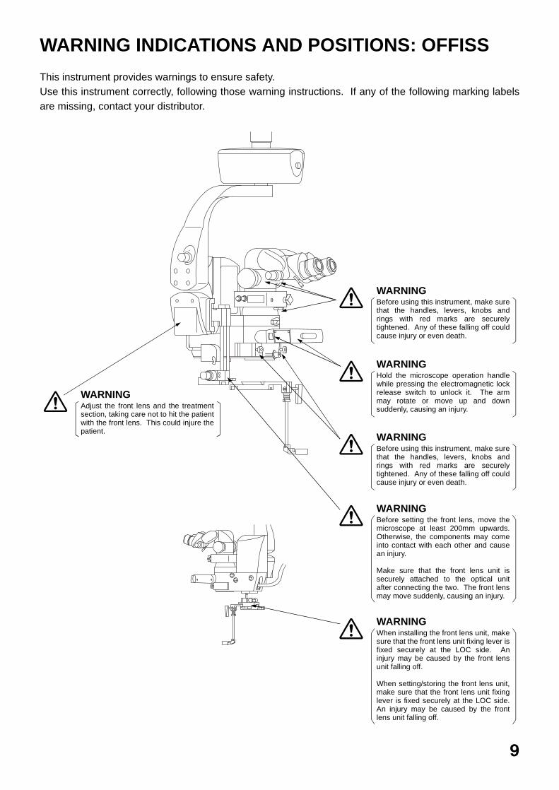
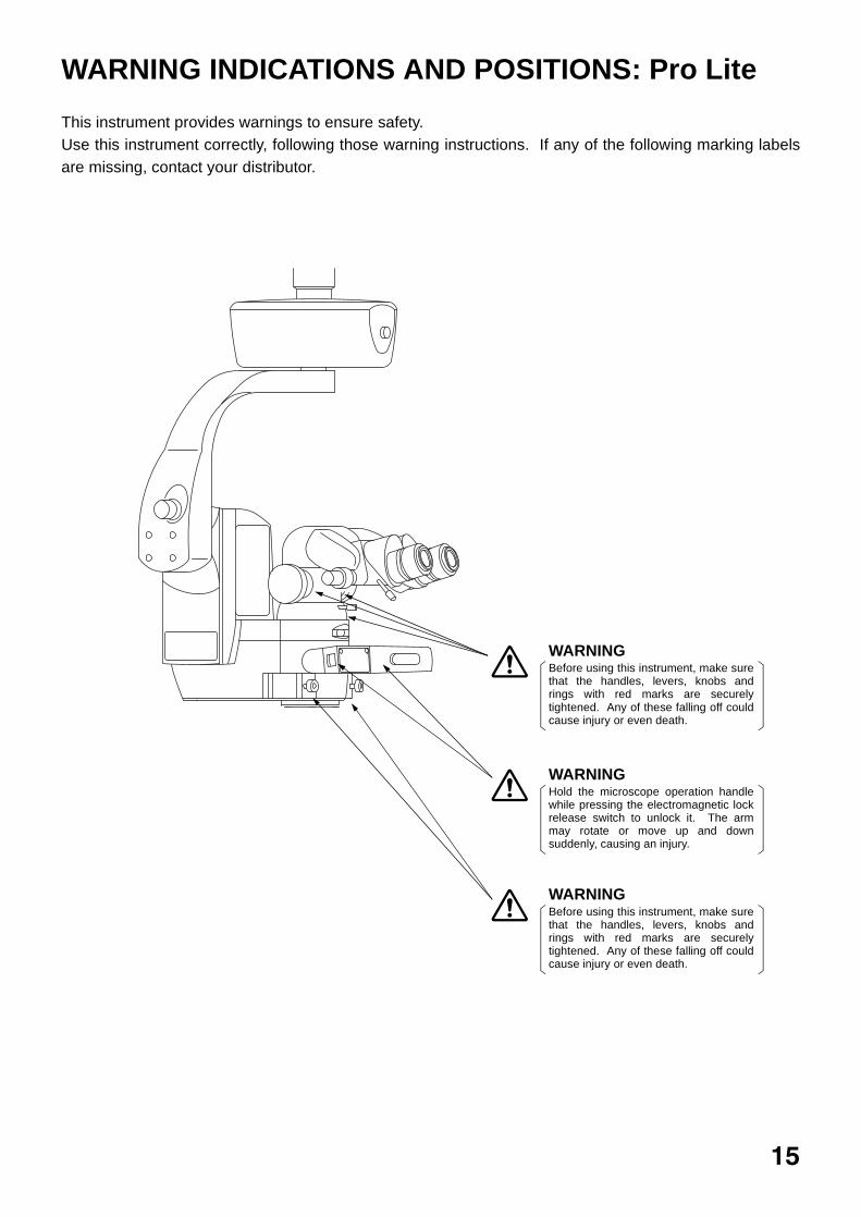
WARNING INDICATIONS AND POSITIONS: OFFISS
This instrument provides warnings to ensure safety.Use this instrument correctly, following those warning instructions. If any of the following marking labelsare missing, contact your distributor.
WARNINGBefore using this instrument, make surethat the handles, levers, knobs andrings with red marks are securelytightened. Any of these falling off couldcause injury or even death.
WARNINGHold the microscope operation handlewhile pressing the electromagnetic lockrelease switch to unlock it. The armmay rotate or move up and downsuddenly, causing an injury.
WARNINGBefore using this instrument, make surethat the handles, levers, knobs andrings with red marks are securelytightened. Any of these falling off couldcause injury or even death.
WARNINGBefore setting the front lens, move themicroscope at least 200mm upwards.Otherwise, the components may comeinto contact with each other and causean injury.
Make sure that the front lens unit issecurely attached to the optical unitafter connecting the two. The front lensmay move suddenly, causing an injury.
WARNINGWhen installing the front lens unit, makesure that the front lens unit fixing lever isfixed securely at the LOC side. Aninjury may be caused by the front lensunit falling off.
When setting/storing the front lens unit,make sure that the front lens unit fixinglever is fixed securely at the LOC side.An injury may be caused by the frontlens unit falling off.
WARNINGAdjust the front lens and the treatmentsection, taking care not to hit the patientwith the front lens. This could injure thepatient.
9
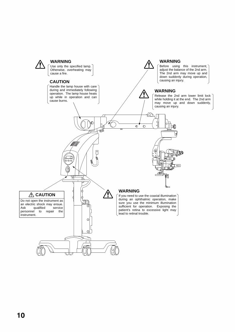
WARNINGRelease the 2nd arm lower limit lockwhile holding it at the end. The 2nd armmay move up and down suddenly,causing an injury.
CAUTIONDo not open the instrument asan electric shock may ensue.Ask qualified servicepersonnel to repair theinstrument.
WARNINGIf you need to use the coaxial illuminationduring an ophthalmic operation, makesure you use the minimum illuminationsufficient for operation. Exposing thepatient’s retina to excessive light maylead to retinal trouble.
WARNINGBefore using this instrument,adjust the balance of the 2nd arm.The 2nd arm may move up anddown suddenly during operation,causing an injury.
WARNINGUse only the specified lamp.Otherwise, overheating maycause a fire.
CAUTIONHandle the lamp house with careduring and immediately followingoperation. The lamp house heatsup while in operation and cancause burns.
10
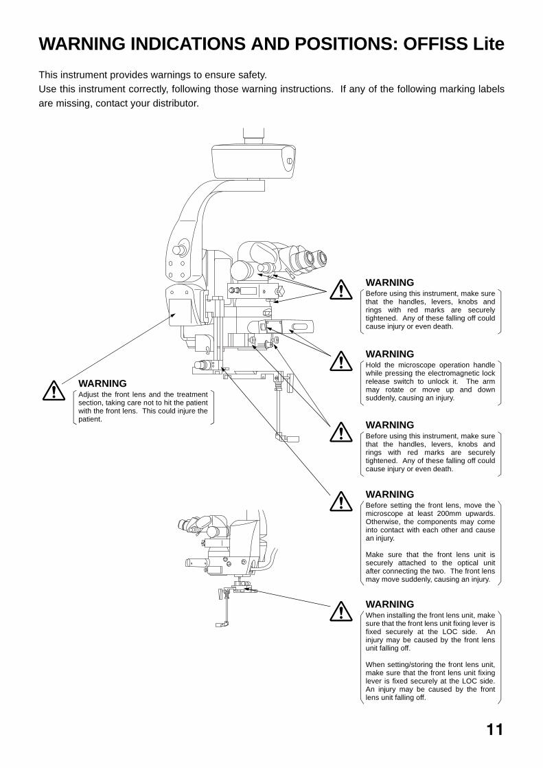
WARNING INDICATIONS AND POSITIONS: OFFISS Lite
This instrument provides warnings to ensure safety.Use this instrument correctly, following those warning instructions. If any of the following marking labelsare missing, contact your distributor.
WARNINGBefore using this instrument, make surethat the handles, levers, knobs andrings with red marks are securelytightened. Any of these falling off couldcause injury or even death.
WARNINGHold the microscope operation handlewhile pressing the electromagnetic lockrelease switch to unlock it. The armmay rotate or move up and downsuddenly, causing an injury.
WARNINGBefore using this instrument, make surethat the handles, levers, knobs andrings with red marks are securelytightened. Any of these falling off couldcause injury or even death.
WARNINGBefore setting the front lens, move themicroscope at least 200mm upwards.Otherwise, the components may comeinto contact with each other and causean injury.
Make sure that the front lens unit issecurely attached to the optical unitafter connecting the two. The front lensmay move suddenly, causing an injury.
WARNINGWhen installing the front lens unit, makesure that the front lens unit fixing lever isfixed securely at the LOC side. Aninjury may be caused by the front lensunit falling off.
When setting/storing the front lens unit,make sure that the front lens unit fixinglever is fixed securely at the LOC side.An injury may be caused by the frontlens unit falling off.
WARNINGAdjust the front lens and the treatmentsection, taking care not to hit the patientwith the front lens. This could injure thepatient.
11
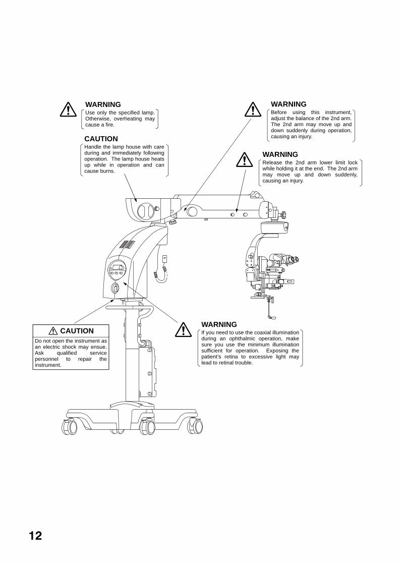
WARNINGRelease the 2nd arm lower limit lockwhile holding it at the end. The 2nd armmay move up and down suddenly,causing an injury.
CAUTIONDo not open the instrument asan electric shock may ensue.Ask qualified servicepersonnel to repair theinstrument.
WARNINGIf you need to use the coaxial illuminationduring an ophthalmic operation, makesure you use the minimum illuminationsufficient for operation. Exposing thepatient’s retina to excessive light maylead to retinal trouble.
WARNINGBefore using this instrument,adjust the balance of the 2nd arm.The 2nd arm may move up anddown suddenly during operation,causing an injury.
WARNINGUse only the specified lamp.Otherwise, overheating maycause a fire.
CAUTIONHandle the lamp house with careduring and immediately followingoperation. The lamp house heatsup while in operation and cancause burns.
12

WARNING INDICATIONS AND POSITIONS: Pro
This instrument provides warnings to ensure safety.Use this instrument correctly, following those warning instructions. If any of the following marking labelsare missing, contact your distributor.
WARNINGBefore using this instrument, make surethat the handles, levers, knobs andrings with red marks are securelytightened. Any of these falling off couldcause injury or even death.
WARNINGHold the microscope operation handlewhile pressing the electromagnetic lockrelease switch to unlock it. The armmay rotate or move up and downsuddenly, causing an injury.
WARNINGBefore using this instrument, make surethat the handles, levers, knobs andrings with red marks are securelytightened. Any of these falling off couldcause injury or even death.
13

WARNINGRelease the 2nd arm lower limit lockwhile holding it at the end. The 2nd armmay move up and down suddenly,causing an injury.
CAUTIONDo not open the instrument asan electric shock may ensue.Ask qualified servicepersonnel to repair theinstrument.
WARNINGBefore using this instrument,adjust the balance of the 2nd arm.The 2nd arm may move up anddown suddenly during operation,causing an injury.
WARNINGUse only the specified lamp.Otherwise, overheating maycause a fire.
CAUTIONHandle the lamp house with careduring and immediately followingoperation. The lamp house heatsup while in operation and cancause burns.
WARNINGIf you need to use the coaxial illuminationduring an ophthalmic operation, makesure you use the minimum illuminationsufficient for operation. Exposing thepatient’s retina to excessive light maylead to retinal trouble.
14
WARNING INDICATIONS AND POSITIONS: Pro Lite
This instrument provides warnings to ensure safety.Use this instrument correctly, following those warning instructions. If any of the following marking labelsare missing, contact your distributor.
WARNINGBefore using this instrument, make surethat the handles, levers, knobs andrings with red marks are securelytightened. Any of these falling off couldcause injury or even death.
WARNINGHold the microscope operation handlewhile pressing the electromagnetic lockrelease switch to unlock it. The armmay rotate or move up and downsuddenly, causing an injury.
WARNINGBefore using this instrument, make surethat the handles, levers, knobs andrings with red marks are securelytightened. Any of these falling off couldcause injury or even death.
15
WARNINGRelease the 2nd arm lower limit lockwhile holding it at the end. The 2nd armmay move up and down suddenly,causing an injury.
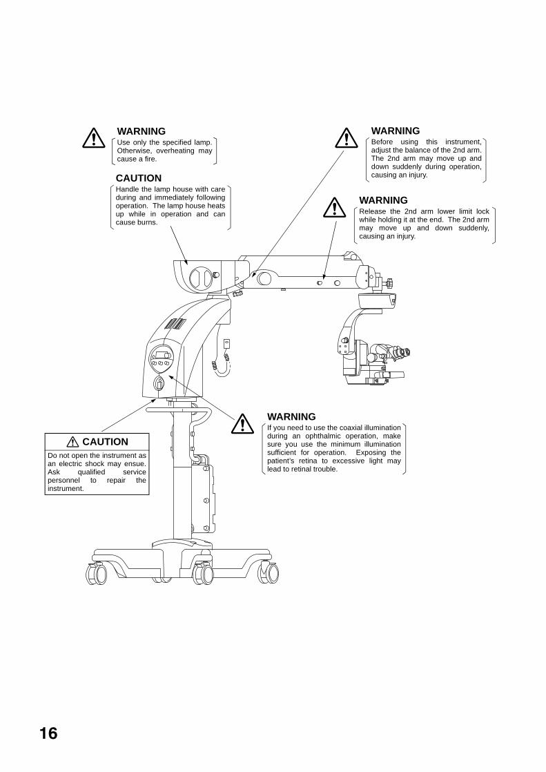
CAUTIONDo not open the instrument asan electric shock may ensue.Ask qualified servicepersonnel to repair theinstrument.
WARNINGBefore using this instrument,adjust the balance of the 2nd arm.The 2nd arm may move up anddown suddenly during operation,causing an injury.
WARNINGUse only the specified lamp.Otherwise, overheating maycause a fire.
CAUTIONHandle the lamp house with careduring and immediately followingoperation. The lamp house heatsup while in operation and cancause burns.
WARNINGIf you need to use the coaxial illuminationduring an ophthalmic operation, makesure you use the minimum illuminationsufficient for operation. Exposing thepatient’s retina to excessive light maylead to retinal trouble.
16

WARNING INDICATIONS AND POSITIONS: Standard
This instrument provides warnings to ensure safety.Use this instrument correctly, following those warning instructions. If any of the following marking labelsare missing, contact your distributor.
WARNINGBefore using this instrument, make surethat the handles, levers, knobs andrings with red marks are securelytightened. Any of these falling off couldcause injury or even death.
WARNINGBefore using this instrument, make surethat the handles, levers, knobs andrings with red marks are securelytightened. Any of these falling off couldcause injury or even death.
17

WARNINGRelease the 2nd arm lower limit lockwhile holding it at the end. The 2nd armmay move up and down suddenly,causing an injury.
CAUTIONDo not open the instrument asan electric shock may ensue.Ask qualified servicepersonnel to repair theinstrument.
WARNINGBefore using this instrument,adjust the balance of the 2nd arm.The 2nd arm may move up anddown suddenly during operation,causing an injury.
WARNINGUse only the specified lamp.Otherwise, overheating maycause a fire.
CAUTIONHandle the lamp house with careduring and immediately followingoperation. The lamp house heatsup while in operation and cancause burns.
WARNINGIf you need to use the coaxial illuminationduring an ophthalmic operation, makesure you use the minimum illuminationsufficient for operation. Exposing thepatient’s retina to excessive light maylead to retinal trouble.
18
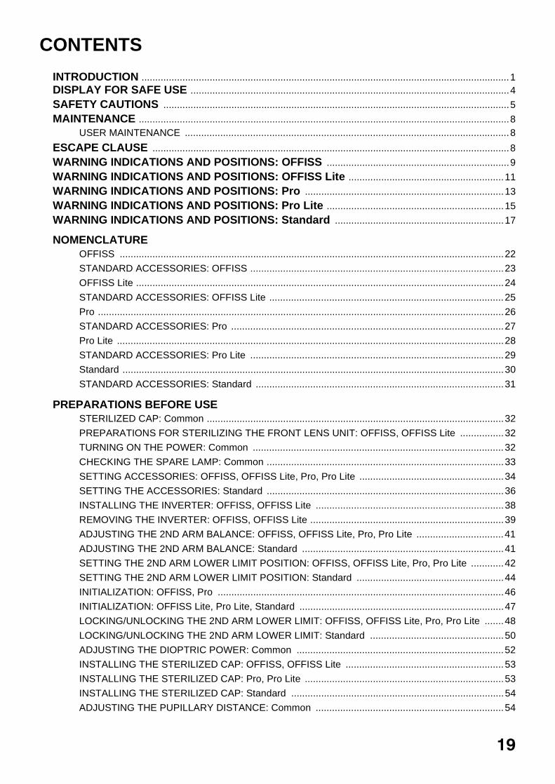
CONTENTS
INTRODUCTION .......................................................................................................................................1DISPLAY FOR SAFE USE .....................................................................................................................4
SAFETY CAUTIONS ...............................................................................................................................5
MAINTENANCE ........................................................................................................................................8USER MAINTENANCE .......................................................................................................................8
ESCAPE CLAUSE ...................................................................................................................................8
WARNING INDICATIONS AND POSITIONS: OFFISS ...................................................................9
WARNING INDICATIONS AND POSITIONS: OFFISS Lite .........................................................11
WARNING INDICATIONS AND POSITIONS: Pro .........................................................................13
WARNING INDICATIONS AND POSITIONS: Pro Lite .................................................................15
WARNING INDICATIONS AND POSITIONS: Standard ..............................................................17
NOMENCLATUREOFFISS .............................................................................................................................................22
STANDARD ACCESSORIES: OFFISS .............................................................................................23
OFFISS Lite .......................................................................................................................................24
STANDARD ACCESSORIES: OFFISS Lite ......................................................................................25
Pro .....................................................................................................................................................26
STANDARD ACCESSORIES: Pro ....................................................................................................27
Pro Lite ..............................................................................................................................................28
STANDARD ACCESSORIES: Pro Lite .............................................................................................29
Standard ............................................................................................................................................30
STANDARD ACCESSORIES: Standard ...........................................................................................31
PREPARATIONS BEFORE USESTERILIZED CAP: Common .............................................................................................................32
PREPARATIONS FOR STERILIZING THE FRONT LENS UNIT: OFFISS, OFFISS Lite ................32
TURNING ON THE POWER: Common ............................................................................................32
CHECKING THE SPARE LAMP: Common .......................................................................................33
SETTING ACCESSORIES: OFFISS, OFFISS Lite, Pro, Pro Lite .....................................................34
SETTING THE ACCESSORIES: Standard .......................................................................................36
INSTALLING THE INVERTER: OFFISS, OFFISS Lite .....................................................................38
REMOVING THE INVERTER: OFFISS, OFFISS Lite .......................................................................39
ADJUSTING THE 2ND ARM BALANCE: OFFISS, OFFISS Lite, Pro, Pro Lite ................................41
ADJUSTING THE 2ND ARM BALANCE: Standard ..........................................................................41
SETTING THE 2ND ARM LOWER LIMIT POSITION: OFFISS, OFFISS Lite, Pro, Pro Lite ............42
SETTING THE 2ND ARM LOWER LIMIT POSITION: Standard ......................................................44
INITIALIZATION: OFFISS, Pro .........................................................................................................46
INITIALIZATION: OFFISS Lite, Pro Lite, Standard ...........................................................................47
LOCKING/UNLOCKING THE 2ND ARM LOWER LIMIT: OFFISS, OFFISS Lite, Pro, Pro Lite .......48
LOCKING/UNLOCKING THE 2ND ARM LOWER LIMIT: Standard .................................................50
ADJUSTING THE DIOPTRIC POWER: Common ............................................................................52
INSTALLING THE STERILIZED CAP: OFFISS, OFFISS Lite ..........................................................53
INSTALLING THE STERILIZED CAP: Pro, Pro Lite .........................................................................53
INSTALLING THE STERILIZED CAP: Standard ..............................................................................54
ADJUSTING THE PUPILLARY DISTANCE: Common .....................................................................54
19
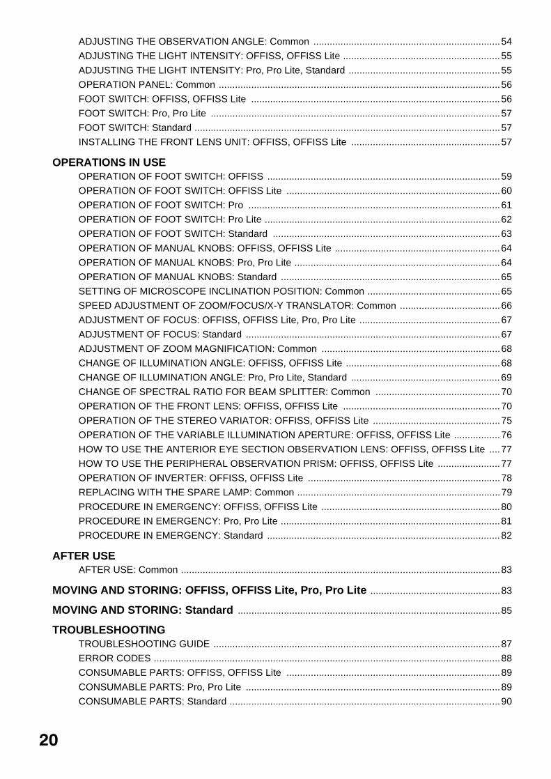
ADJUSTING THE OBSERVATION ANGLE: Common .....................................................................54
ADJUSTING THE LIGHT INTENSITY: OFFISS, OFFISS Lite ..........................................................55
ADJUSTING THE LIGHT INTENSITY: Pro, Pro Lite, Standard ........................................................55
OPERATION PANEL: Common ........................................................................................................56
FOOT SWITCH: OFFISS, OFFISS Lite ............................................................................................56
FOOT SWITCH: Pro, Pro Lite ...........................................................................................................57
FOOT SWITCH: Standard .................................................................................................................57
INSTALLING THE FRONT LENS UNIT: OFFISS, OFFISS Lite .......................................................57
OPERATIONS IN USEOPERATION OF FOOT SWITCH: OFFISS ......................................................................................59
OPERATION OF FOOT SWITCH: OFFISS Lite ...............................................................................60
OPERATION OF FOOT SWITCH: Pro .............................................................................................61
OPERATION OF FOOT SWITCH: Pro Lite .......................................................................................62
OPERATION OF FOOT SWITCH: Standard ....................................................................................63
OPERATION OF MANUAL KNOBS: OFFISS, OFFISS Lite .............................................................64
OPERATION OF MANUAL KNOBS: Pro, Pro Lite ............................................................................64
OPERATION OF MANUAL KNOBS: Standard .................................................................................65
SETTING OF MICROSCOPE INCLINATION POSITION: Common .................................................65
SPEED ADJUSTMENT OF ZOOM/FOCUS/X-Y TRANSLATOR: Common .....................................66
ADJUSTMENT OF FOCUS: OFFISS, OFFISS Lite, Pro, Pro Lite ....................................................67
ADJUSTMENT OF FOCUS: Standard ..............................................................................................67
ADJUSTMENT OF ZOOM MAGNIFICATION: Common ..................................................................68
CHANGE OF ILLUMINATION ANGLE: OFFISS, OFFISS Lite .........................................................68
CHANGE OF ILLUMINATION ANGLE: Pro, Pro Lite, Standard .......................................................69
CHANGE OF SPECTRAL RATIO FOR BEAM SPLITTER: Common ..............................................70
OPERATION OF THE FRONT LENS: OFFISS, OFFISS Lite ..........................................................70
OPERATION OF THE STEREO VARIATOR: OFFISS, OFFISS Lite ...............................................75
OPERATION OF THE VARIABLE ILLUMINATION APERTURE: OFFISS, OFFISS Lite .................76
HOW TO USE THE ANTERIOR EYE SECTION OBSERVATION LENS: OFFISS, OFFISS Lite ....77
HOW TO USE THE PERIPHERAL OBSERVATION PRISM: OFFISS, OFFISS Lite .......................77
OPERATION OF INVERTER: OFFISS, OFFISS Lite .......................................................................78
REPLACING WITH THE SPARE LAMP: Common ...........................................................................79
PROCEDURE IN EMERGENCY: OFFISS, OFFISS Lite ..................................................................80
PROCEDURE IN EMERGENCY: Pro, Pro Lite .................................................................................81
PROCEDURE IN EMERGENCY: Standard ......................................................................................82
AFTER USEAFTER USE: Common ......................................................................................................................83
MOVING AND STORING: OFFISS, OFFISS Lite, Pro, Pro Lite ................................................83
MOVING AND STORING: Standard .................................................................................................85
TROUBLESHOOTINGTROUBLESHOOTING GUIDE ..........................................................................................................87
ERROR CODES ................................................................................................................................88
CONSUMABLE PARTS: OFFISS, OFFISS Lite ...............................................................................89
CONSUMABLE PARTS: Pro, Pro Lite ..............................................................................................89
CONSUMABLE PARTS: Standard ....................................................................................................90
20

SPECIFICATIONSBASIC SPECIFICATIONS: Common ................................................................................................91
ELECTROMAGNETIC COMPATIBILITY ..........................................................................................91
ELECTRIC RATING ..........................................................................................................................95
CLASSIFICATION .............................................................................................................................95
DIMENSIONS AND WEIGHT ............................................................................................................96
PURPOSE OF USE ..........................................................................................................................96
OPERATION PRINCIPLE .................................................................................................................96
MAINTENANCE AND INSPECTION: CommonREPLACEMENT OF THE SPARE LAMP .........................................................................................97
OPERATING THE CIRCUIT BREAKER ...........................................................................................98
CHECKING THE POWER OUTLET ...............................................................................................100
CHECKING INPUT VOLTAGE ........................................................................................................100
CLEANING THE OBJECTIVE LENS / THE EYEPIECE LENS .......................................................101
CLEANING THE FRONT LENS STORING UNIT: OFFISS, OFFISS Lite ......................................101
CLEANING THE REST APART FROM THE OPTICAL SYSTEM ..................................................102
ENSURING THE SAFETY WORK ..................................................................................................102
DAILY CHECK ................................................................................................................................103
DISPOSITION .................................................................................................................................103
SYSTEM OUTLINE .........................................................................................................................104
PERMITTED WEIGHT FOR ACCESSORIES TO BE INSTALLED .................................................106
WEIGHT OF OPTIONAL ACCESSORIES ......................................................................................106
21

NOMENCLATUREOFFISS
EXIT
SPARE
MAIN
FOCUS XYZOOM
12 3 4
5 12 3 4
5 12 3 4
5
R
R
Illumination angle manual knob (for emergency)
Front lens unit fixing lever
Variable illumination aperture manual knob (for emergency)
Microscope unit
Zoom manual knob (for emergency)
Spectral ratio knob
Type with the changeable beam splitter
Spectral ratio lever Focusing unitAccessories mount capAccessories mounting ring
Accessories mount
Variable eyepiece lens
Eyepiece lens
Observation angle handle
Pupillary distance adjustment knob
Beam splitter or changeable beam splitterManual IN/OUT knob (for emergency)InverterIN indicator LEDEyepiece lens/beam splitter fixing knobZoom magnification display window
Microscope operation handleElectromagnetic lock release switchStereo variator lever0 assistant�s microscope fixing knobObjective lens0 assistant�s microscope mountFront lens IN/OUT leverFront lens holding shaftFront lens
Front lens unitFront lens storing unit
Front lens connecting unit
Front lens connecting/disconnecting knob
Slide shaftConnecting hook
Optical unit
Front lens fine movement unit
Optical unit inclination knob
Light intensity display window
Illumination light intensity adjustment knob
Spare lamp indicator lightX-Y translator speed knobFocusing unit speed knobZoom speed knobEXIT switchPower indicator light
Power switch
Circuit breaker
Base unit
2nd arm
End rubber coverRough focusing unit
X-Y translator rotation fixing handle
Initial switch
X-Y translator
Focusing unit arm
0 assistant�s microscope mount cover
Balance display window
2nd arm lower limit knob
2nd arm lower limit lock release knob
2nd arm balance adjustment handleElectromagnetic lock release switch
Cord hanger
Foot switch hanger
Foot switch supportProtector
Caster lock lever
CasterBubble level
Right/left bases
Center base
Column
Base movement handle
Operation panel
1st arm
Filter knob
Lamp house unit
Foot switchCarrying handle
Rough focusing switch/front lens focusing switch
Illumination angle switch
X-Y translator lever switch
Zoom up/down switch
Spare switch
*Switch layout when shipped
Invereter in/out switch
Foot rest
Focus up/down switch
Illumination blinking switch
Illumination light intensity adjustment switch/variable illuminationoperture switch
2nd arm side-front cover
2nd arm side-rear cover
22NOMENCLATURE
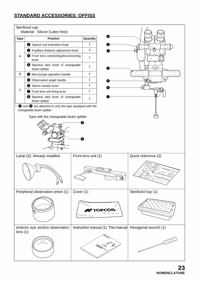
STANDARD ACCESSORIES: OFFISS
Sterilized capMaterial : Silicon (Latex free)
Lamp (2): Already installed. Front lens unit (1) Quick reference (2)
Peripheral observation prism (1) Cover (1) Sterilized tray (1)
Anterior eye section observationlens (1)
Instruction manual (1): This manual Hexagonal wrench (1)
4
2
1
3
5
6
7
* and are attached to only the type equipped with thechangeable beam splitter.
Type Position Quantity
A
Optical unit inclination knob 1
Pupillary distance adjustment knob 2
Front lens connecting/disconnectingknob
1
Spectral ratio knob of changeablebeam splitter
1
B Microscope operation handle 2
C
Observation angle handle 1
Stereo variator lever 1
Front lens unit fixing lever 1
Spectral ratio lever of changeablebeam splitter
1
1
2
6
8
3
4
5
7
9
8 9
Type with the changeable beam splitter
8
9
23NOMENCLATURE

OFFISS Lite
EXIT
SPARE
MAIN
FOCUS XYZOOM
12 3 4
5 12 3 4
5 12 3 4
5
R
R
Illumination angle manual knob (for emergency)
Front lens unit fixing lever
Variable illumination aperture manual knob (for emergency)
Microscope unit
Zoom manual knob (for emergency)
Spectral ratio knob
Type with the changeable beam splitter
Spectral ratio lever Focusing unitAccessories mount capAccessories mounting ring
Accessories mount
Variable eyepiece lens
Eyepiece lens
Observation angle handle
Pupillary distance adjustment knob
Beam splitter or changeable beam splitterManual IN/OUT knob (for emergency)InverterIN indicator LEDEyepiece lens/beam splitter fixing knobZoom magnification display window
Microscope operation handleElectromagnetic lock release switchStereo variator lever0 assistant�s microscope fixing knobObjective lens0 assistant�s microscope mountFront lens IN/OUT leverFront lens holding shaftFront lens
Front lens unitFront lens storing unit
Front lens connecting unit
Front lens connecting/disconnecting knob
Slide shaftConnecting hook
Optical unit
Front lens fine movement unit
Optical unit inclination knob
Light intensity display window
Illumination light intensity adjustment knob
Spare lamp indicator lightX-Y translator speed knobFocusing unit speed knobZoom speed knobEXIT switchPower indicator light
Power switch
Circuit breaker
Base unit
2nd armEnd rubber cover
X-Y translator rotation fixing handle
Initial switch
X-Y translator
Focusing unit arm
0 assistant�s microscope mount cover
Balance display window
2nd arm lower limit knob
2nd arm lower limit lock release knob
2nd arm balance adjustment handleElectromagnetic lock release switch
Cord hanger
Foot switch hanger
Foot switch supportProtector
Caster lock lever
CasterBubble level
Right/left bases
Center base
Column
Base movement handle
Operation panel
1st arm
Filter knob
Lamp house unit
Foot switchCarrying handle
Front lens focusing switch
Illumination angle switch
X-Y translator lever switch
Zoom up/down switch
Spare switch
*Switch layout when shipped
Inverter in/out switch
Foot rest
Focus up/down switch
Illumination blinking switch
Illumination light intensity adjustment switch/variable illuminationoperture switch
2nd arm side-front cover
2nd arm side-rear cover
24NOMENCLATURE
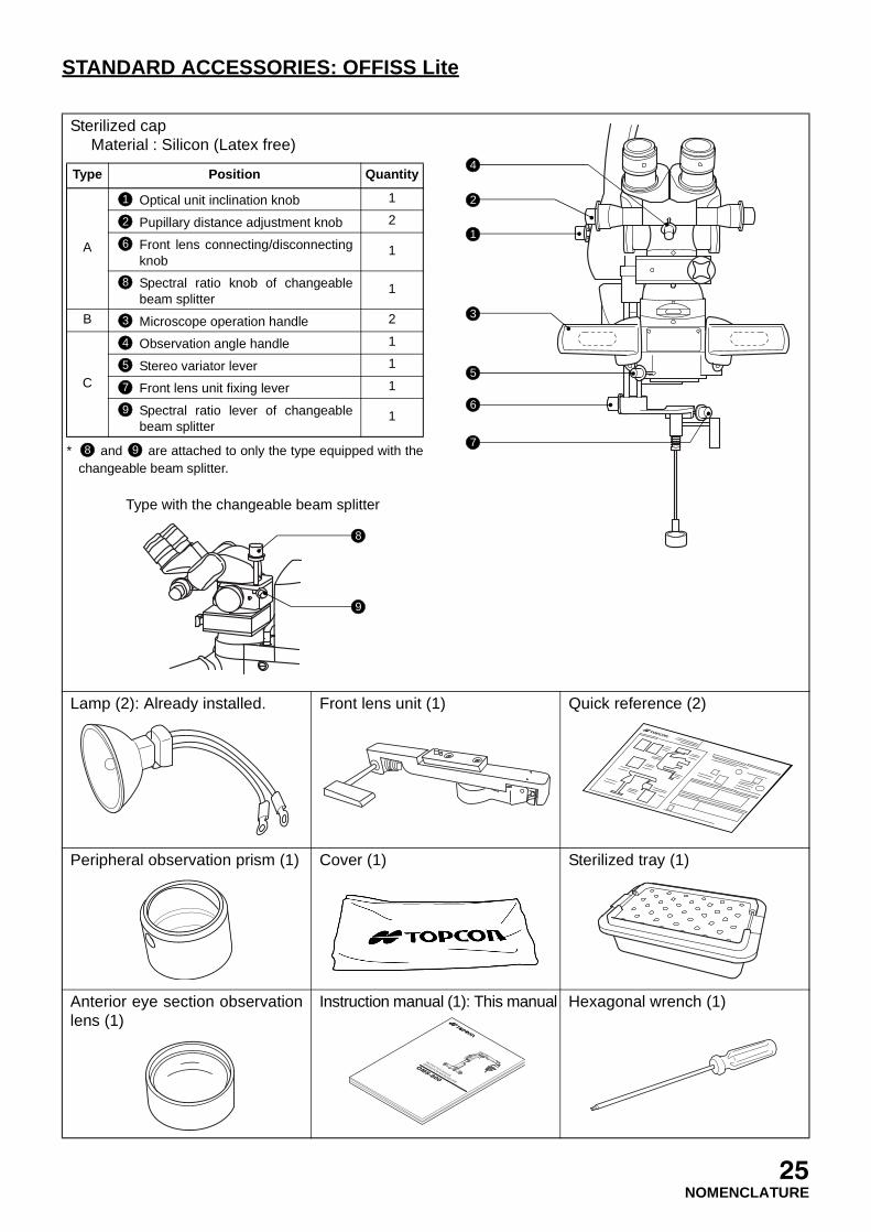
STANDARD ACCESSORIES: OFFISS Lite
Sterilized capMaterial : Silicon (Latex free)
Lamp (2): Already installed. Front lens unit (1) Quick reference (2)
Peripheral observation prism (1) Cover (1) Sterilized tray (1)
Anterior eye section observationlens (1)
Instruction manual (1): This manual Hexagonal wrench (1)
4
2
1
3
5
6
7* and are attached to only the type equipped with the
changeable beam splitter.
Type Position Quantity
A
Optical unit inclination knob 1
Pupillary distance adjustment knob 2
Front lens connecting/disconnectingknob
1
Spectral ratio knob of changeablebeam splitter
1
B Microscope operation handle 2
C
Observation angle handle 1
Stereo variator lever 1
Front lens unit fixing lever 1
Spectral ratio lever of changeablebeam splitter
1
1
2
6
8
3
4
5
7
9
8 9
Type with the changeable beam splitter
8
9
25NOMENCLATURE
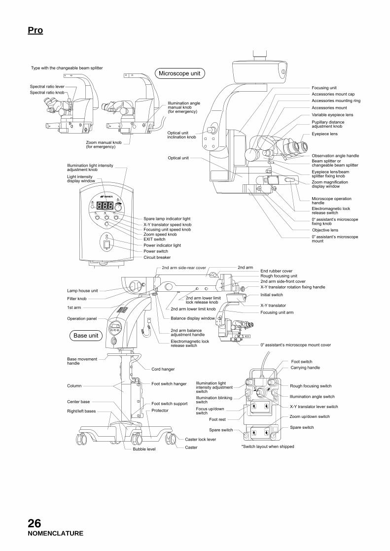
Pro
EXIT
SPARE
MAIN
FOCUS XYZOOM
12 3 4
5 12 3 4
5 12 3 4
5
Light intensity display window
Illumination light intensity adjustment knob
Spare lamp indicator lightX-Y translator speed knobFocusing unit speed knobZoom speed knobEXIT switchPower indicator lightPower switchCircuit breaker
Foot switchCarrying handle
Illumination angle switch
X-Y translator lever switch
Zoom up/down switch
Spare switch
Rough focusing switch
*Switch layout when shipped
Spare switch
Foot rest
Focus up/down switch
Illumination blinking switch
Illumination light intensity adjustment switch
Microscope unit
Base unit
Illumination angle manual knob (for emergency)
Zoom manual knob (for emergency)
Focusing unitAccessories mount capAccessories mounting ring
Accessories mount
Variable eyepiece lens
Eyepiece lens
Observation angle handle
Pupillary distance adjustment knob
Beam splitter or changeable beam splitterEyepiece lens/beam splitter fixing knobZoom magnification display window
Microscope operation handleElectromagnetic lock release switch0 assistant�s microscope fixing knobObjective lens0 assistant�s microscope mount
Optical unit
Optical unit inclination knob
2nd armEnd rubber coverRough focusing unit2nd arm side-front coverX-Y translator rotation fixing handle
Initial switch
X-Y translator
Focusing unit arm
0 assistant�s microscope mount cover
Balance display window
2nd arm lower limit knob
2nd arm lower limit lock release knob
2nd arm balance adjustment handleElectromagnetic lock release switch
Cord hanger
Foot switch hanger
Foot switch supportProtector
Caster lock lever
CasterBubble level
Right/left bases
Center base
Column
Base movement handle
Operation panel
1st arm
Filter knob
Lamp house unit
Spectral ratio knob
Type with the changeable beam splitter
Spectral ratio lever
2nd arm side-rear cover
26NOMENCLATURE
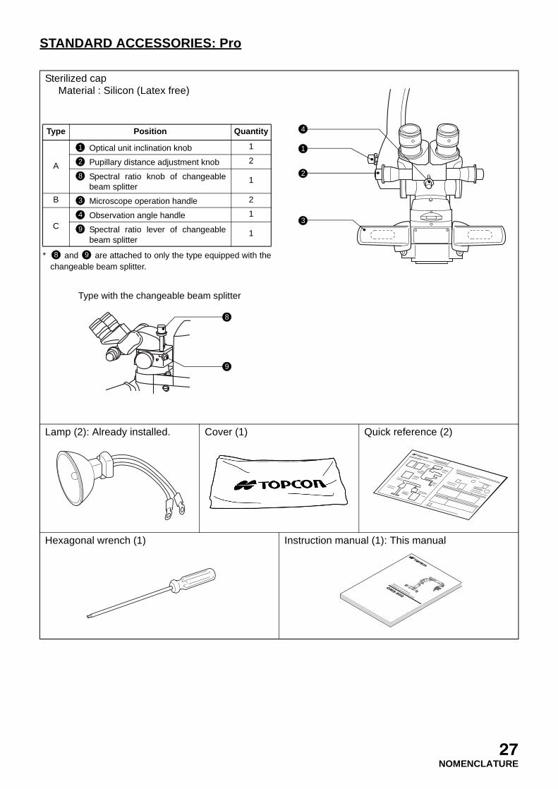
STANDARD ACCESSORIES: Pro
Sterilized capMaterial : Silicon (Latex free)
Lamp (2): Already installed. Cover (1) Quick reference (2)
Hexagonal wrench (1) Instruction manual (1): This manual
* and are attached to only the type equipped with thechangeable beam splitter.
Type Position Quantity
A
Optical unit inclination knob 1
Pupillary distance adjustment knob 2
Spectral ratio knob of changeablebeam splitter
1
B Microscope operation handle 2
CObservation angle handle 1
Spectral ratio lever of changeablebeam splitter
1
1
2
8
3
4
9
8 9
Type with the changeable beam splitter
8
9
4
1
2
3
27NOMENCLATURE

Pro Lite
EXIT
SPARE
MAIN
FOCUS XYZOOM
12 3 4
5 12 3 4
5 12 3 4
5
Light intensity display window
Illumination light intensity adjustment knob
Spare lamp indicator lightX-Y translator speed knobFocusing unit speed knobZoom speed knobEXIT switchPower indicator lightPower switchCircuit breaker
Microscope unit
Illumination angle manual knob (for emergency)
Zoom manual knob (for emergency)
Focusing unitAccessories mount capAccessories mounting ring
Accessories mount
Variable eyepiece lens
Eyepiece lens
Observation angle handle
Pupillary distance adjustment knob
Beam splitter or changeable beam splitterEyepiece lens/beam splitter fixing knobZoom magnification display window
Microscope operation handleElectromagnetic lock release switch0 assistant�s microscope fixing knobObjective lens0 assistant�s microscope mount
Optical unit
Optical unit inclination knob
Spectral ratio knob
Type with the changeable beam splitter
Spectral ratio lever
Foot switchCarrying handle
Illumination angle switch
X-Y translator lever switch
Zoom up/down switch
Spare switch
Spare switch
*Switch layout when shipped
Spare switch
Foot rest
Focus up/down switch
Illumination blinking switch
Illumination light intensity adjustment switch
Base unit
2nd armEnd rubber cover
2nd arm side-front coverX-Y translator rotation fixing handle
Initial switch
X-Y translator
Focusing unit arm
0 assistant�s microscope mount cover
Balance display window
2nd arm lower limit knob
2nd arm lower limit lock release knob
2nd arm balance adjustment handleElectromagnetic lock release switch
Cord hanger
Foot switch hanger
Foot switch supportProtector
Caster lock lever
CasterBubble level
Right/left bases
Center base
Column
Base movement handle
Operation panel
1st arm
Filter knob
Lamp house unit
2nd arm side-rear cover
28NOMENCLATURE

STANDARD ACCESSORIES: Pro Lite
Sterilized capMaterial : Silicon (Latex free)
Lamp (2): Already installed. Cover (1) Quick reference (2)
Hexagonal wrench (1) nstruction manual (1): This manual
* and are attached to only the type equipped with thechangeable beam splitter.
Type Position Quantity
A
Optical unit inclination knob 1
Pupillary distance adjustment knob 2
Spectral ratio knob of changeablebeam splitter
1
B Microscope operation handle 2
CObservation angle handle 1
Spectral ratio lever of changeablebeam splitter
1
1
2
8
3
4
9
8 9
Type with the changeable beam splitter
8
9
4
1
2
3
29NOMENCLATURE

Standard
EXIT
SPARE
MAIN
FOCUS XYZOOM
12 3 4
5 12 3 4
5 12 3 4
5
Light intensity display window
Illumination light intensity adjustment knob
Spare lamp indicator lightX-Y translator speed knobFocusing unit speed knobZoom speed knobEXIT switch
Power indicator light
Power switchCircuit breaker
Microscope unit
Illumination angle manual knob (for emergency)
Zoom manual knob (for emergency)
Optical unit
Optical unit inclination knob
Focusing unitAccessories mount capAccessories mounting ring
Accessories mount
Variable eyepiece lens
Eyepiece lens
Observation angle handle
Pupillary distance adjustment knob
Beam splitter orchangeable beam splitterEyepiece lens/beam splitter fixing knobZoom magnification display windowMicroscope operation handle
0 assistant�s microscope fixing knobObjective lens0 assistant�s microscope mount
Foot switchCarrying handle
Illumination angle switch
X-Y translator lever switch
Zoom up/down switch
Spare switch
Spare switch
*Switch layout when shipped
Spare switch
Foot rest
Focus up/down switch
Illumination blinking switch
Illumination light intensity adjustment switch
Base unit
2nd arm
0 assistant�s microscope mount cover
Balance display window
2nd arm lower limit knob
2nd arm lower limit lock release knob
2nd arm balance adjustment handle
2nd arm rotationfixing handle
Cord hanger
Foot switch hanger
Foot switch supportProtector
Bubble level
Caster lock lever
Caster
Right/left bases
Center base
Column
Base movement handle
Operation panel
1st arm
Filter knob
Lamp house unit
End rubber cover
2nd arm side-front cover
X-Y translator rotation fixing handle
Initial switch
X-Y translator
Focusing unit arm
2nd arm vertical movement fixing handle
1st arm rotation fixing handle
Spectral ratio knob
Type with the changeable beam splitter
Spectral ratio lever
2nd arm side-rear cover
30NOMENCLATURE

STANDARD ACCESSORIES: Standard
Sterilized capMaterial : Silicon (Latex free)
Lamp (2): Already installed. Cover (1) Quick reference (2)
Hexagonal wrench (1) Instruction manual (1): This manual
* and are attached to only the type equipped with thechangeable beam splitter.
Type Position Quantity
A
Optical unit inclination knob 1
Pupillary distance adjustment knob 2
Spectral ratio knob of changeablebeam splitter
1
B Microscope operation handle 2
CObservation angle handle 1
Spectral ratio lever of changeablebeam splitter
1
1
2
8
3
4
9
8 9
Type with the changeable beam splitter
8
9
4
1
2
3
31NOMENCLATURE
PREPARATIONS BEFORE USE
Before using this instrument, carry out the daily check. (Refer to "DAILY CHECK" on P.103.)
STERILIZED CAP: Common
Sterilize caps as follows:
Method: High pressure steam sterilizationCondition: Leave cap in the saturated steam (134±4°C) for 20 minutes.
PREPARATIONS FOR STERILIZING THE FRONT LENS UNIT: OFFISS, OFFISS Lite
Place the front lens unit, peripheral prism and anterior eye section observation lens in the sterilized trayand sterilize them as follows:
Method: EOG (ethylene oxide gas) sterilizationCondition: Make sure the devices used are properly sterilized.
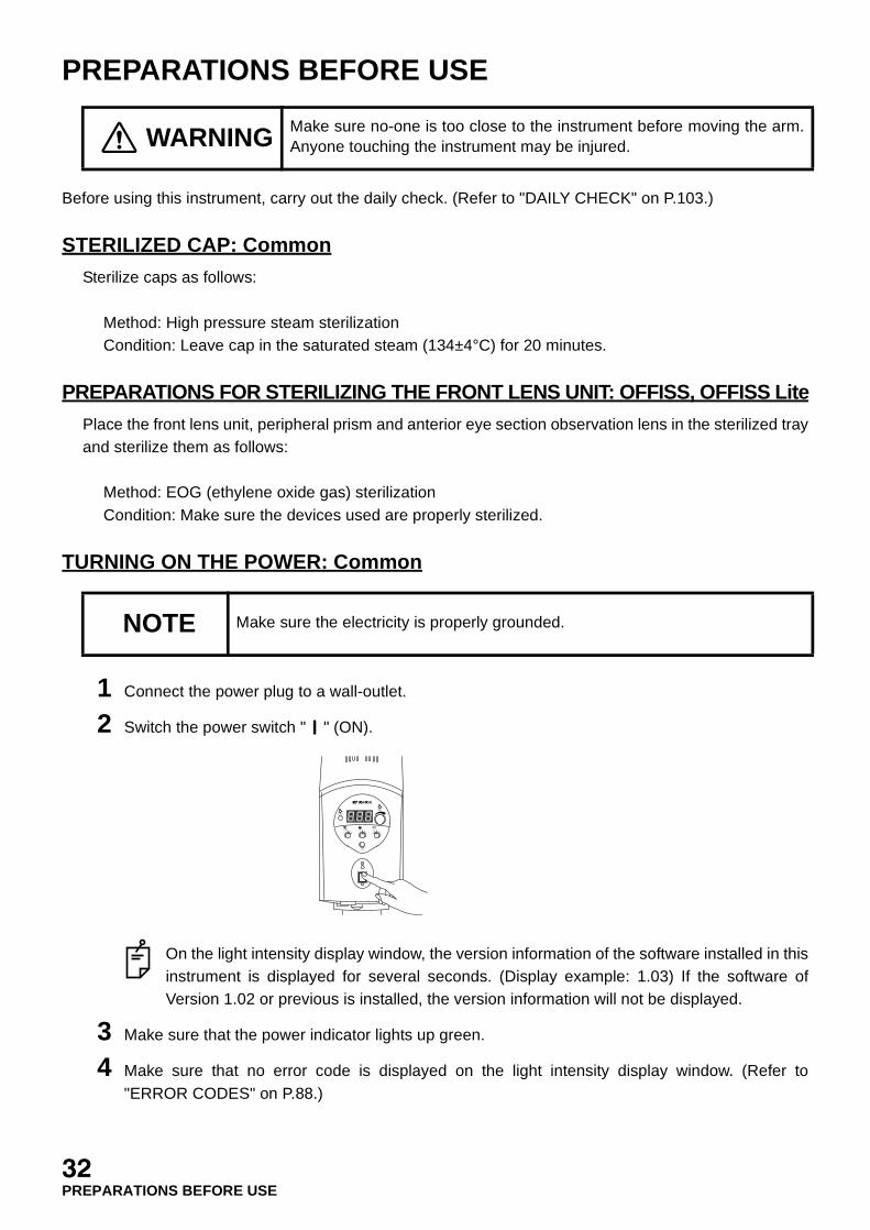
TURNING ON THE POWER: Common
1 Connect the power plug to a wall-outlet.
2 Switch the power switch " " (ON).
On the light intensity display window, the version information of the software installed in thisinstrument is displayed for several seconds. (Display example: 1.03) If the software ofVersion 1.02 or previous is installed, the version information will not be displayed.
3 Make sure that the power indicator lights up green.
4 Make sure that no error code is displayed on the light intensity display window. (Refer to"ERROR CODES" on P.88.)
WARNING Make sure no-one is too close to the instrument before moving the arm.Anyone touching the instrument may be injured.
NOTE Make sure the electricity is properly grounded.
EXIT
SPARE
MAIN
FOCUS XYZOOM
12 3 4
5 12 3 4
5 12 3 4
5
32PREPARATIONS BEFORE USE
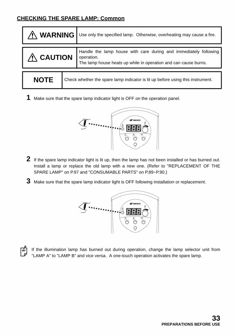
CHECKING THE SPARE LAMP: Common
1 Make sure that the spare lamp indicator light is OFF on the operation panel.
2 If the spare lamp indicator light is lit up, then the lamp has not been installed or has burned out.Install a lamp or replace the old lamp with a new one. (Refer to "REPLACEMENT OF THESPARE LAMP" on P.97 and "CONSUMABLE PARTS" on P.89~P.90.)
3 Make sure that the spare lamp indicator light is OFF following installation or replacement.
If the illumination lamp has burned out during operation, change the lamp selector unit from"LAMP A" to "LAMP B" and vice versa. A one-touch operation activates the spare lamp.
WARNING Use only the specified lamp. Otherwise, overheating may cause a fire.
CAUTIONHandle the lamp house with care during and immediately followingoperation. The lamp house heats up while in operation and can cause burns.
NOTE Check whether the spare lamp indicator is lit up before using this instrument.
EXIT
SPARE
MAIN
FOCUS XYZOOM
12 3 4
5 12 3 4
5 12 3 4
5
EXIT
SPARE
MAIN
FOCUS XYZOOM
12 3 4
5 12 3 4
5 12 3 4
5
33PREPARATIONS BEFORE USE
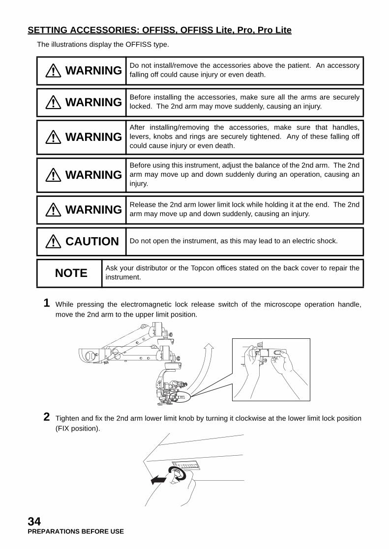
SETTING ACCESSORIES: OFFISS, OFFISS Lite, Pro, Pro Lite
The illustrations display the OFFISS type.
1 While pressing the electromagnetic lock release switch of the microscope operation handle,move the 2nd arm to the upper limit position.
2 Tighten and fix the 2nd arm lower limit knob by turning it clockwise at the lower limit lock position(FIX position).
WARNING Do not install/remove the accessories above the patient. An accessoryfalling off could cause injury or even death.
WARNING Before installing the accessories, make sure all the arms are securelylocked. The 2nd arm may move suddenly, causing an injury.
WARNINGAfter installing/removing the accessories, make sure that handles,levers, knobs and rings are securely tightened. Any of these falling offcould cause injury or even death.
WARNINGBefore using this instrument, adjust the balance of the 2nd arm. The 2ndarm may move up and down suddenly during an operation, causing aninjury.
WARNING Release the 2nd arm lower limit lock while holding it at the end. The 2ndarm may move up and down suddenly, causing an injury.
CAUTION Do not open the instrument, as this may lead to an electric shock.
NOTE Ask your distributor or the Topcon offices stated on the back cover to repair theinstrument.
34PREPARATIONS BEFORE USE
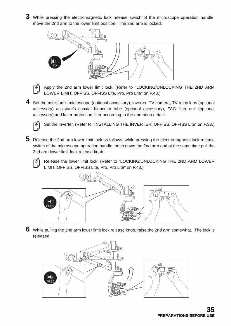
3 While pressing the electromagnetic lock release switch of the microscope operation handle,move the 2nd arm to the lower limit position. The 2nd arm is locked.
Apply the 2nd arm lower limit lock. (Refer to "LOCKING/UNLOCKING THE 2ND ARMLOWER LIMIT: OFFISS, OFFISS Lite, Pro, Pro Lite" on P.48.)
4 Set the assistant's microscope (optional accessory), inverter, TV camera, TV relay lens (optionalaccessory) assistant’s coaxial binocular tube (optional accessory), FAG filter unit (optionalaccessory) and laser protection filter according to the operation details.
Set the inverter. (Refer to "INSTALLING THE INVERTER: OFFISS, OFFISS Lite" on P.38.)
5 Release the 2nd arm lower limit lock as follows: while pressing the electromagnetic lock releaseswitch of the microscope operation handle, push down the 2nd arm and at the same time pull the2nd arm lower limit lock release knob.
Release the lower limit lock. (Refer to "LOCKING/UNLOCKING THE 2ND ARM LOWERLIMIT: OFFISS, OFFISS Lite, Pro, Pro Lite" on P.48.)
6 While pulling the 2nd arm lower limit lock release knob, raise the 2nd arm somewhat. The lock isreleased.
FIX
FREE
FREE
35PREPARATIONS BEFORE USE
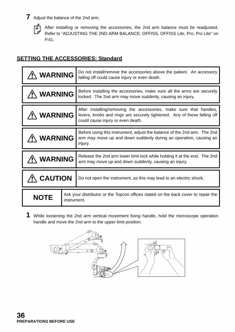
7 Adjust the balance of the 2nd arm.
After installing or removing the accessories, the 2nd arm balance must be readjusted.Refer to "ADJUSTING THE 2ND ARM BALANCE: OFFISS, OFFISS Lite, Pro, Pro Lite" onP.41.
SETTING THE ACCESSORIES: Standard
1 While loosening the 2nd arm vertical movement fixing handle, hold the microscope operationhandle and move the 2nd arm to the upper limit position.
WARNING Do not install/remove the accessories above the patient. An accessoryfalling off could cause injury or even death.
WARNING Before installing the accessories, make sure all the arms are securelylocked. The 2nd arm may move suddenly, causing an injury.
WARNINGAfter installing/removing the accessories, make sure that handles,levers, knobs and rings are securely tightened. Any of these falling offcould cause injury or even death.
WARNINGBefore using this instrument, adjust the balance of the 2nd arm. The 2ndarm may move up and down suddenly during an operation, causing aninjury.
WARNING Release the 2nd arm lower limit lock while holding it at the end. The 2ndarm may move up and down suddenly, causing an injury.
CAUTION Do not open the instrument, as this may lead to an electric shock.
NOTE Ask your distributor or the Topcon offices stated on the back cover to repair theinstrument.
36PREPARATIONS BEFORE USE

2 Tighten and fix the 2nd arm lower limit knob by turning it clockwise at the lower limit lock position(FIX position).
3 While loosening the 2nd arm vertical movement fixing handle, hold the microscope operationhandle and move the 2nd arm to the lower limit position. The 2nd arm is locked.
Apply the 2nd arm lower limit lock. (Refer to "LOCKING/UNLOCKING THE 2ND ARMLOWER LIMIT: Standard" on P.50.)
4 Set the assistant's microscope (optional accessory), inverter, TV camera, TV relay lens (optionalaccessory), assistant’s coaxial binocular tube (optional accessory), FAG filter unit (optionalaccessory) and laser protection filter according to the operation details.
5 Release the 2nd arm lower limit lock as follows: while loosening the 2nd arm vertical movementfixing handle, hold the microscope operation handle, push down the 2nd arm and at the sametime pull the 2nd arm lower limit lock release knob.
Release the lower limit lock. (Refer to "LOCKING/UNLOCKING THE 2ND ARM LOWERLIMIT: Standard" on P.50.)
FIX
FREE
37PREPARATIONS BEFORE USE

6 While pulling the 2nd arm lower limit lock release knob, raise the 2nd arm somewhat. The lock isreleased.
7 Adjust the balance of the 2nd arm.
After installing or removing the accessories, the 2nd arm balance must be readjusted.Refer to "ADJUSTING THE 2ND ARM BALANCE: Standard" on P.41.
INSTALLING THE INVERTER: OFFISS, OFFISS Lite
1 Loosen the eyepiece lens/beam splitter fixing knob on the microscope unit and then remove theeyepiece lens/beam splitter from the microscope.
2 Fit the groove of the inverter to the pin on the top side of the microscope and tighten the eyepiecelens/beam splitter fixing knob to fix the inverter.
We recommend using a hexagonal screwdriver.
FREE
38PREPARATIONS BEFORE USE
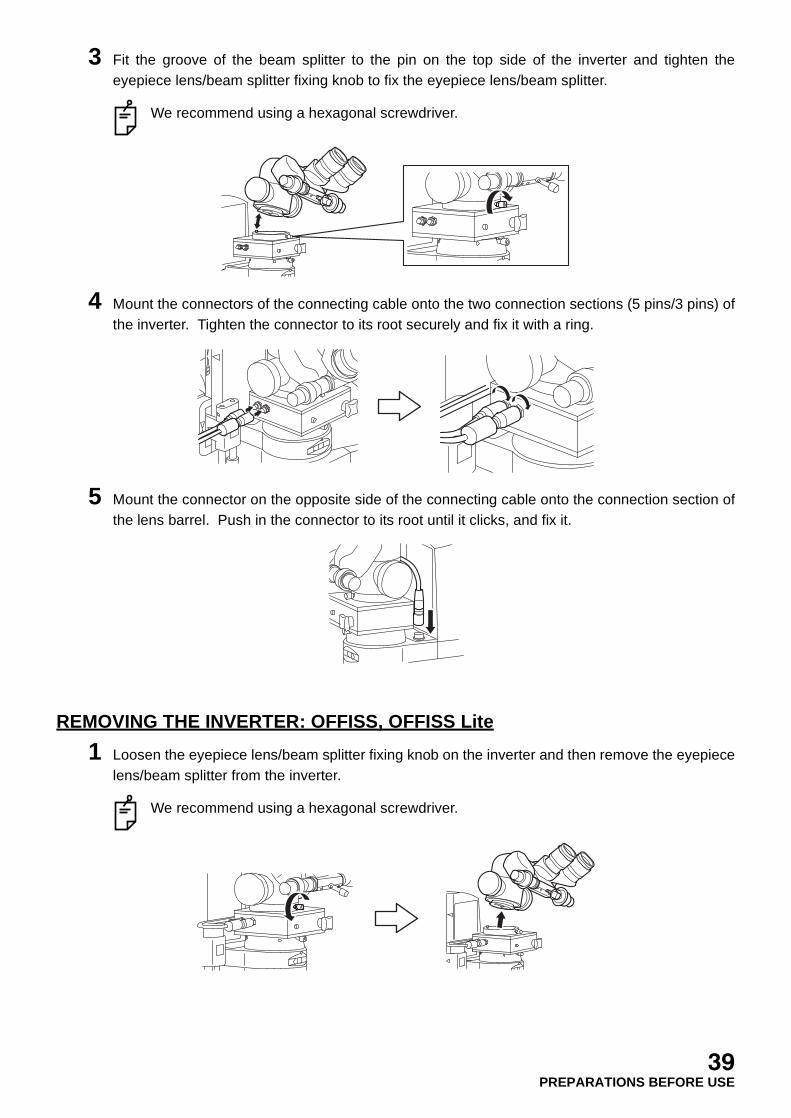
3 Fit the groove of the beam splitter to the pin on the top side of the inverter and tighten theeyepiece lens/beam splitter fixing knob to fix the eyepiece lens/beam splitter.
We recommend using a hexagonal screwdriver.
4 Mount the connectors of the connecting cable onto the two connection sections (5 pins/3 pins) ofthe inverter. Tighten the connector to its root securely and fix it with a ring.
5 Mount the connector on the opposite side of the connecting cable onto the connection section ofthe lens barrel. Push in the connector to its root until it clicks, and fix it.
REMOVING THE INVERTER: OFFISS, OFFISS Lite
1 Loosen the eyepiece lens/beam splitter fixing knob on the inverter and then remove the eyepiecelens/beam splitter from the inverter.
We recommend using a hexagonal screwdriver.
39PREPARATIONS BEFORE USE

2 Remove the connector (on the lens barrel side) of the connecting cable. Pull up the connector assliding its end section (shadowed section as shown below) upward.
3 Remove the connector (on the inverter side) of the connecting cable. Loosen the tightening ringat the connector's end section and then remove the connector.
We recommend storing the removed connecting cable in the inverter's carry case.
4 Loosen the eyepiece lens/beam splitter fixing knob on the operation microscope OMS-800 andthen remove the inverter from the microscope.
We recommend using a hexagonal screwdriver.
We recommend storing the removed inverter in the inverter's carry case.
40PREPARATIONS BEFORE USE

ADJUSTING THE 2ND ARM BALANCE: OFFISS, OFFISS Lite, Pro, Pro Lite
1 While pressing the electromagnetic lock release switch, move the 2nd arm equally far up anddown.If the arm moves upward too lightly, turn the 2nd arm balance adjustment handle clockwise(A).The arm will move heavily.A number will be displayed on the balance display window. The higher the number, the larger thebalance mass.
If the arm moves down too heavily, turn the 2nd arm balance adjustment handle counter-clockwise (B). The arm will move lightly.
Installing or removing accessories will change the arm balance setting. Therefore, alwaysreset the balance in the vertical direction, according to the instructions above.
ADJUSTING THE 2ND ARM BALANCE: Standard
WARNINGHold the microscope operation handle while pressing theelectromagnetic lock release switch to unlock it. The arm may rotate ormove up and down suddenly, causing an injury.
WARNING Before installing the accessories, make sure all the arms are securelylocked. The 2nd arm may move suddenly, causing an injury.
A
B
41PREPARATIONS BEFORE USE

1 Loosen the 2nd arm vertical movement fixing handle and hold the microscope operation handle.Then move the 2nd arm equally far up and down.If the arm moves upward too lightly, turn the 2ndarm balance adjustment handle clockwise(A).The arm will move heavily.
If the arm moves down too heavily, turn the 2ndarm balance adjustment handle counter-clockwise (B). The arm will move lightly.
Installing or removing accessories willchange the arm balance setting.Therefore, always reset the balance in thevertical direction, according to theinstructions above.
SETTING THE 2ND ARM LOWER LIMIT POSITION: OFFISS, OFFISS Lite, Pro,Pro Lite
The illustrations display the OFFISS type.Limit unnecessary downward movement in order to prevent or reduce accidents caused by adownward movement of the 2nd arm.
WARNINGHold the microscope operation handle while pressing theelectromagnetic lock release switch to unlock it. The arm may rotate ormove up and down suddenly, causing an injury.
WARNING Before installing the accessories, make sure all the arms are securelylocked. The 2nd arm may move suddenly, causing an injury.
WARNING The gas spring in the 2nd arm contains high-pressure gas. Do notdisassemble the 2nd arm or expose it to fire. You may be injured.
WARNINGBefore using this instrument, adjust the balance of the 2nd arm. The 2ndarm may move up and down suddenly during an operation, causing aninjury.
A
B
42PREPARATIONS BEFORE USE
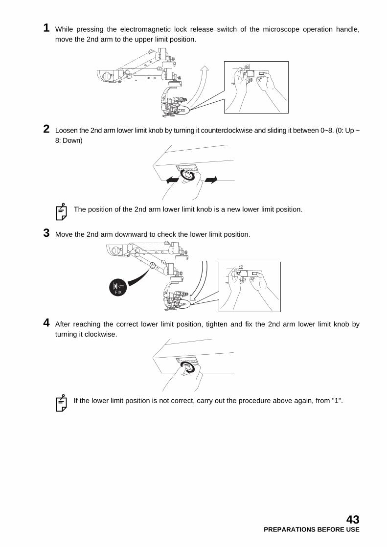
1 While pressing the electromagnetic lock release switch of the microscope operation handle,move the 2nd arm to the upper limit position.
2 Loosen the 2nd arm lower limit knob by turning it counterclockwise and sliding it between 0~8. (0: Up ~8: Down)
The position of the 2nd arm lower limit knob is a new lower limit position.
3 Move the 2nd arm downward to check the lower limit position.
4 After reaching the correct lower limit position, tighten and fix the 2nd arm lower limit knob byturning it clockwise.
If the lower limit position is not correct, carry out the procedure above again, from "1".
FIX
43PREPARATIONS BEFORE USE

SETTING THE 2ND ARM LOWER LIMIT POSITION: Standard
Limit unnecessary downward movement in order to prevent or reduce accidents caused by adownward movement of the 2nd arm.
1 While loosening the 2nd arm vertical movement fixing handle, hold the microscope operationhandle and move the 2nd arm to the upper limit position.
2 Loosen the 2nd arm lower limit knob by turning it counterclockwise and sliding it between 0~8. (0: Up ~8: Down)
The position of the 2nd arm lower limit knob is a new lower limit position.
WARNINGAlways hold the microscope operation handle when loosening either the2nd arm vertical movement fixing handle, the 2nd arm rotation fixinghandle or the 1st arm rotation fixing handle. The arm may rotate or moveup and down suddenly, causing an injury.
WARNING Before installing the accessories, make sure all the arms are securelylocked. The 2nd arm may move suddenly, causing an injury.
WARNING The gas spring in the 2nd arm contains high-pressure gas. Do notdisassemble the 2nd arm or expose it to fire. You may be injured.
WARNINGBefore using this instrument, adjust the balance of the 2nd arm. The 2ndarm may move up and down suddenly during an operation, causing aninjury.
44PREPARATIONS BEFORE USE
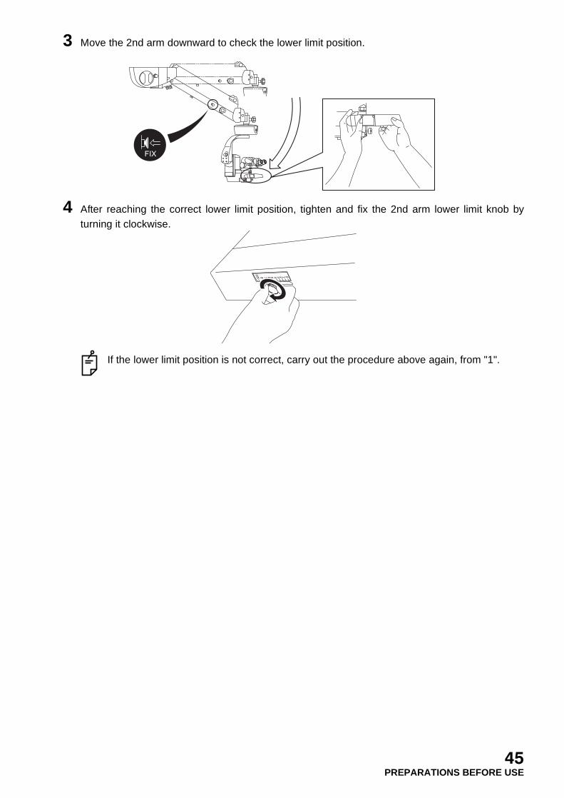
3 Move the 2nd arm downward to check the lower limit position.
4 After reaching the correct lower limit position, tighten and fix the 2nd arm lower limit knob byturning it clockwise.
If the lower limit position is not correct, carry out the procedure above again, from "1".
FIX
45PREPARATIONS BEFORE USE
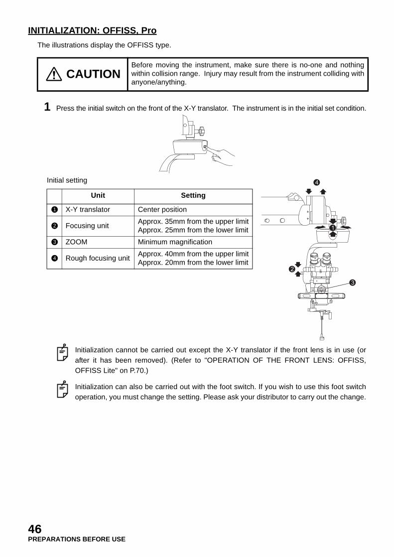
INITIALIZATION: OFFISS, Pro
The illustrations display the OFFISS type.
1 Press the initial switch on the front of the X-Y translator. The instrument is in the initial set condition.
Initial setting
Initialization cannot be carried out except the X-Y translator if the front lens is in use (orafter it has been removed). (Refer to "OPERATION OF THE FRONT LENS: OFFISS,OFFISS Lite" on P.70.)
Initialization can also be carried out with the foot switch. If you wish to use this foot switchoperation, you must change the setting. Please ask your distributor to carry out the change.
CAUTIONBefore moving the instrument, make sure there is no-one and nothingwithin collision range. Injury may result from the instrument colliding withanyone/anything.
Unit Setting
X-Y translator Center position
Focusing unitApprox. 35mm from the upper limitApprox. 25mm from the lower limit
ZOOM Minimum magnification
Rough focusing unitApprox. 40mm from the upper limitApprox. 20mm from the lower limit
1
4
3
2
1
2
3
4
46PREPARATIONS BEFORE USE
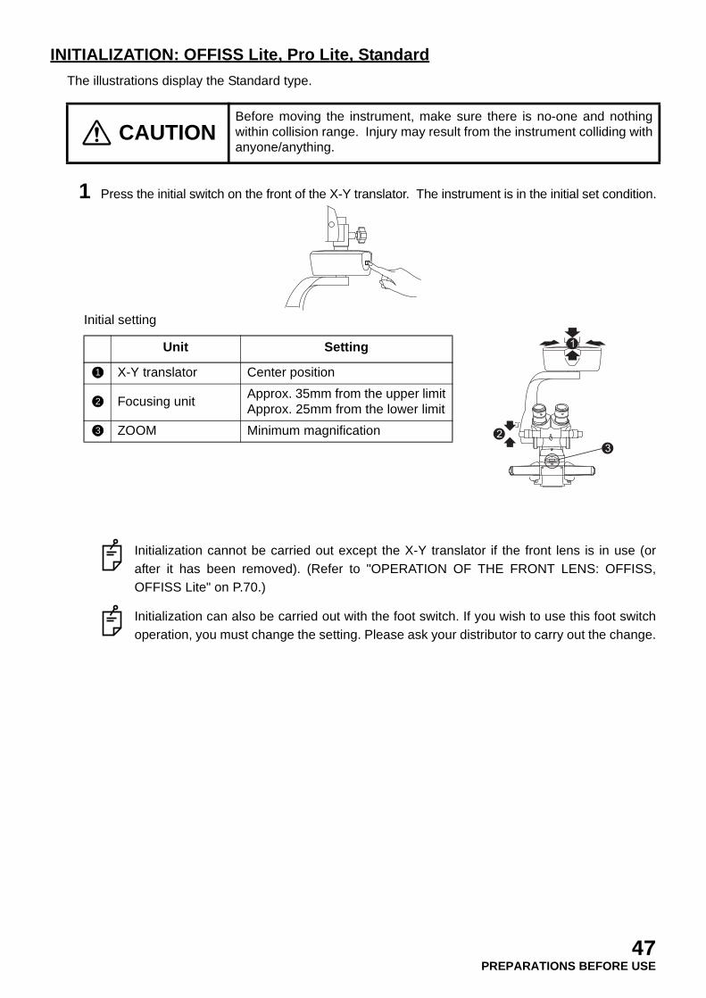
INITIALIZATION: OFFISS Lite, Pro Lite, Standard
The illustrations display the Standard type.
1 Press the initial switch on the front of the X-Y translator. The instrument is in the initial set condition.
Initial setting
Initialization cannot be carried out except the X-Y translator if the front lens is in use (orafter it has been removed). (Refer to "OPERATION OF THE FRONT LENS: OFFISS,OFFISS Lite" on P.70.)
Initialization can also be carried out with the foot switch. If you wish to use this foot switchoperation, you must change the setting. Please ask your distributor to carry out the change.
CAUTIONBefore moving the instrument, make sure there is no-one and nothingwithin collision range. Injury may result from the instrument colliding withanyone/anything.
Unit Setting
X-Y translator Center position
Focusing unitApprox. 35mm from the upper limitApprox. 25mm from the lower limit
ZOOM Minimum magnification
1
32
1
2
3
47PREPARATIONS BEFORE USE

LOCKING/UNLOCKING THE 2ND ARM LOWER LIMIT: OFFISS, OFFISS Lite,Pro, Pro Lite
The illustrations display the OFFISS type.Use this lock when moving/storing this instrument or when installing/removing the accessories.
2nd arm lower limit lock
1 While pressing the electromagnetic lock release switch of the microscope operation handle,move the 2nd arm to the upper limit position.
2 Loosen the 2nd arm lower limit knob by turning it counterclockwise and slide it to the FIXposition.
WARNING Release the 2nd arm lower limit lock while holding it at the end. The 2ndarm may move up and down suddenly, causing an injury.
WARNINGHold the microscope operation handle while pressing theelectromagnetic lock release switch to unlock it. The arm may rotate ormove up and down suddenly, causing an injury.
WARNING Before installing the accessories, make sure all the arms are securelylocked. The 2nd arm may move suddenly, causing an injury.
WARNING The gas spring in the 2nd arm contains high-pressure gas. Do notdisassemble the 2nd arm or expose it to fire. You may be injured.
WARNINGBefore using this instrument, adjust the balance of the 2nd arm. The 2ndarm may move up and down suddenly during an operation, causing aninjury.
48PREPARATIONS BEFORE USE
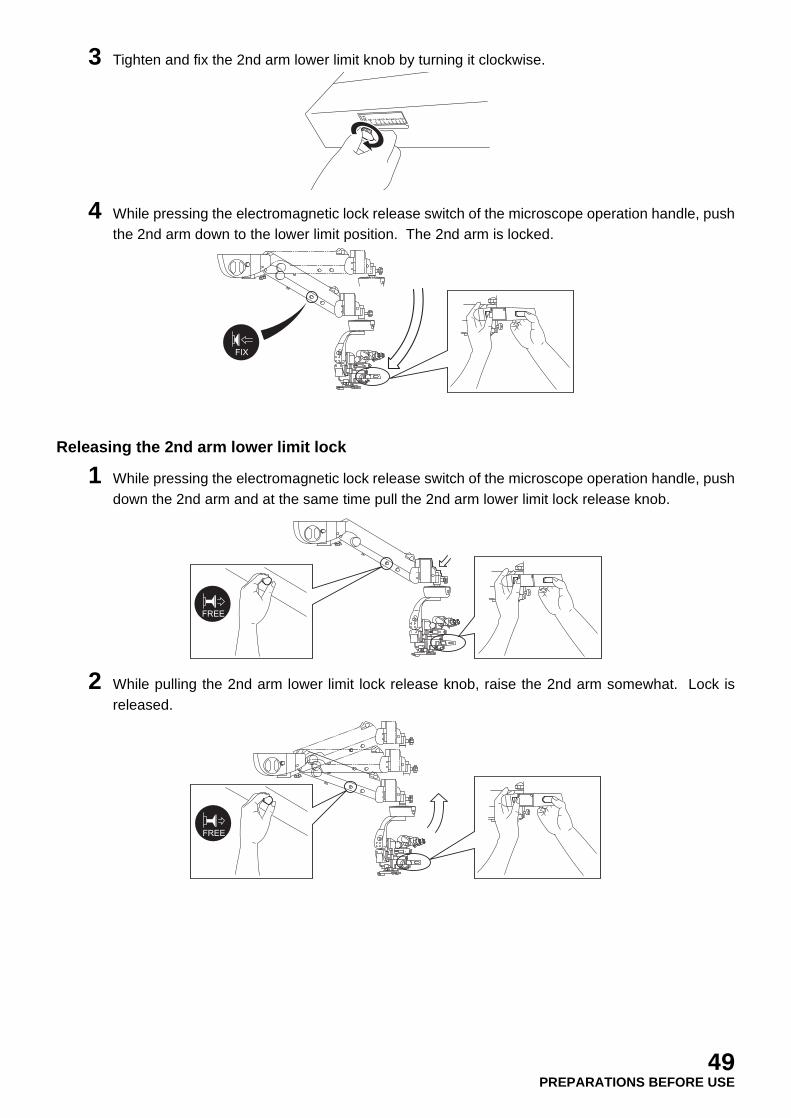
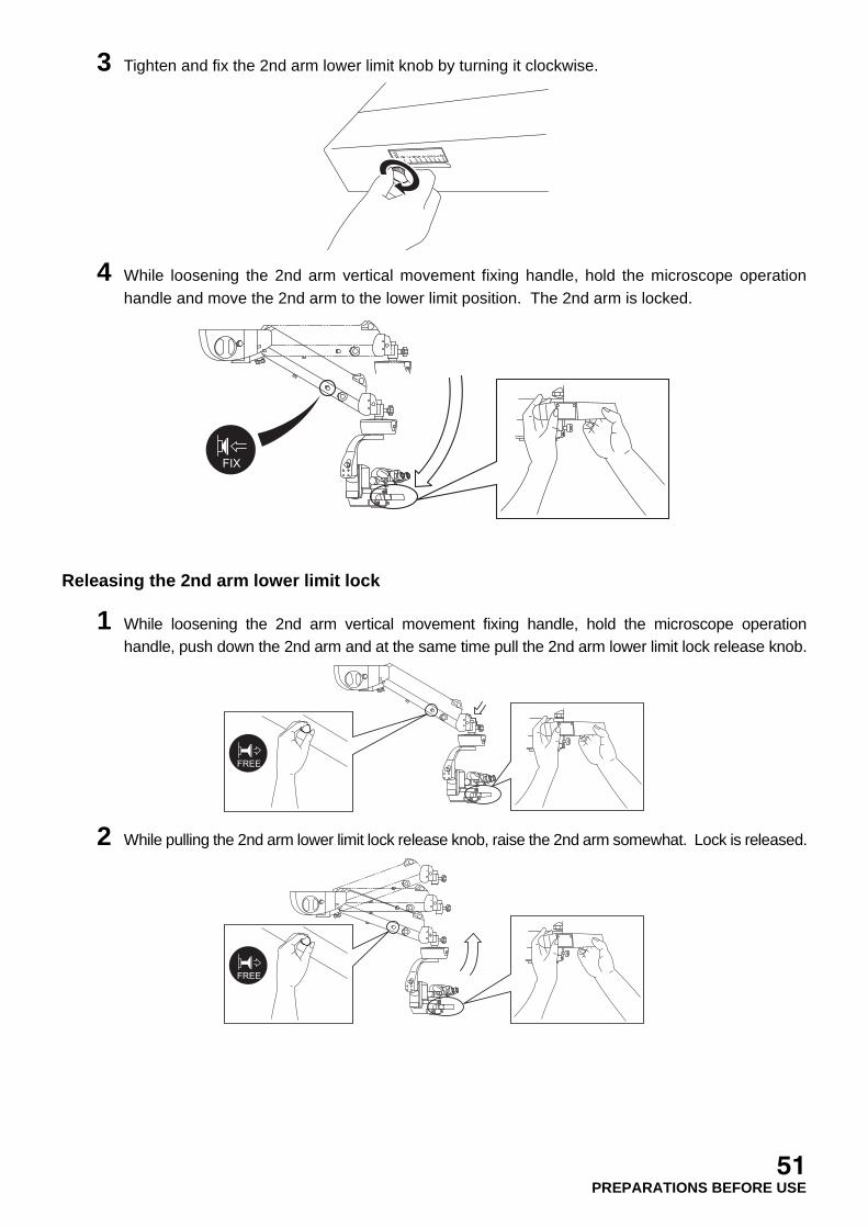
3 Tighten and fix the 2nd arm lower limit knob by turning it clockwise.
4 While pressing the electromagnetic lock release switch of the microscope operation handle, pushthe 2nd arm down to the lower limit position. The 2nd arm is locked.
Releasing the 2nd arm lower limit lock
1 While pressing the electromagnetic lock release switch of the microscope operation handle, pushdown the 2nd arm and at the same time pull the 2nd arm lower limit lock release knob.
2 While pulling the 2nd arm lower limit lock release knob, raise the 2nd arm somewhat. Lock isreleased.
FIX
FREE
FREE
49PREPARATIONS BEFORE USE
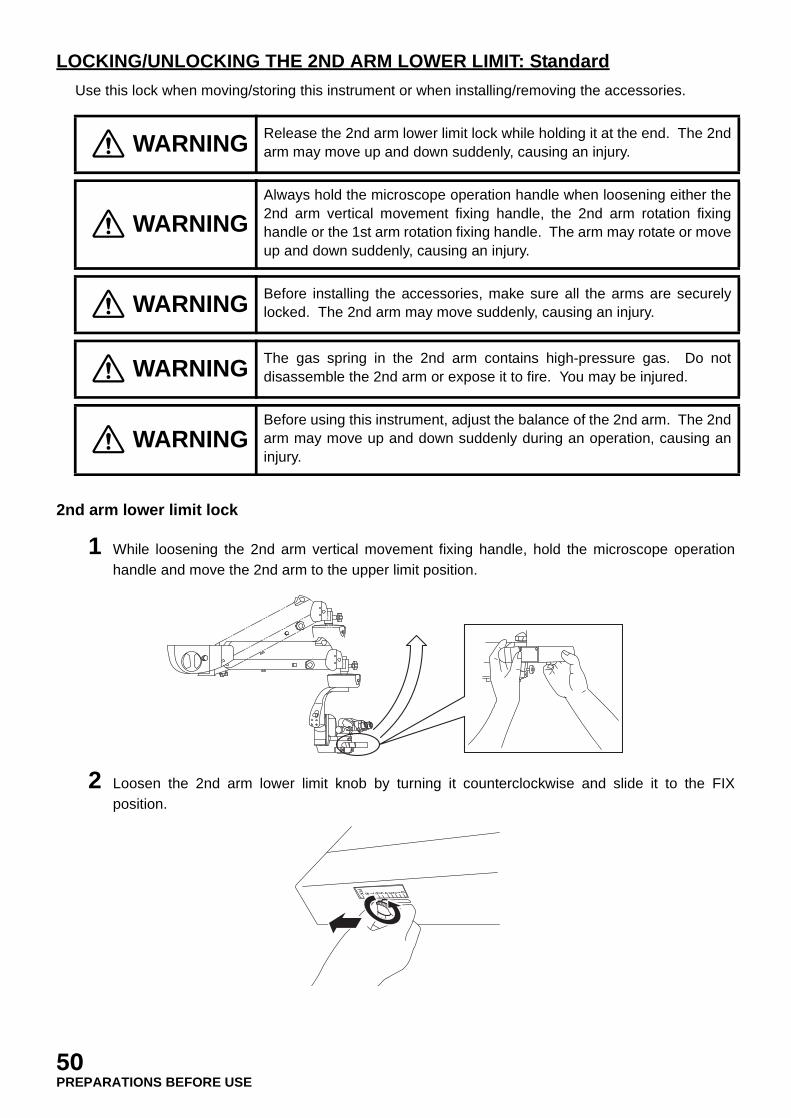
LOCKING/UNLOCKING THE 2ND ARM LOWER LIMIT: Standard
Use this lock when moving/storing this instrument or when installing/removing the accessories.
2nd arm lower limit lock
1 While loosening the 2nd arm vertical movement fixing handle, hold the microscope operationhandle and move the 2nd arm to the upper limit position.
2 Loosen the 2nd arm lower limit knob by turning it counterclockwise and slide it to the FIXposition.
WARNING Release the 2nd arm lower limit lock while holding it at the end. The 2ndarm may move up and down suddenly, causing an injury.
WARNINGAlways hold the microscope operation handle when loosening either the2nd arm vertical movement fixing handle, the 2nd arm rotation fixinghandle or the 1st arm rotation fixing handle. The arm may rotate or moveup and down suddenly, causing an injury.
WARNING Before installing the accessories, make sure all the arms are securelylocked. The 2nd arm may move suddenly, causing an injury.
WARNING The gas spring in the 2nd arm contains high-pressure gas. Do notdisassemble the 2nd arm or expose it to fire. You may be injured.
WARNINGBefore using this instrument, adjust the balance of the 2nd arm. The 2ndarm may move up and down suddenly during an operation, causing aninjury.
50PREPARATIONS BEFORE USE
3 Tighten and fix the 2nd arm lower limit knob by turning it clockwise.
4 While loosening the 2nd arm vertical movement fixing handle, hold the microscope operationhandle and move the 2nd arm to the lower limit position. The 2nd arm is locked.
Releasing the 2nd arm lower limit lock
1 While loosening the 2nd arm vertical movement fixing handle, hold the microscope operationhandle, push down the 2nd arm and at the same time pull the 2nd arm lower limit lock release knob.
2 While pulling the 2nd arm lower limit lock release knob, raise the 2nd arm somewhat. Lock is released.
FIX
FREE
FREE
51PREPARATIONS BEFORE USE

ADJUSTING THE DIOPTRIC POWER: Common
1 Operate the zoom up/down switch of the foot switch to set the observation magnification atmaximum value.
2 Turn the diopter adjustment ring counterclockwise to its maximum value and gently move themicroscope unit up and down with the focus up/down switch until the object is in focus.
3 Operate the zoom up/down switch of the foot switch to set the observation magnification atminimum value.
4 While looking through the eyepiece lens for each eye, turn its diopter adjustment ring clockwiseuntil the object is in focus and can be clearly seen. The dioptric power is now properly adjusted.The scale of the diopter adjustment ring displays the correct dioptric power.
Record the correct dioptric power for each eye. Then adjust the dioptric power to thevalue.
52PREPARATIONS BEFORE USE

INSTALLING THE STERILIZED CAP: OFFISS, OFFISS Lite
Sterilize the sterilized caps and then place them in the specified positions. The following table displaysthe setting positions of the sterilized caps.
* and are attached to only the type equipped with the changeable beam splitter.
INSTALLING THE STERILIZED CAP: Pro, Pro Lite
Sterilize the sterilized caps and then place them in the specified positions. The following table displaysthe setting positions of the sterilized caps.
* and are attached to only the type equipped with the changeable beam splitter.
Type Position Quantity
A
Optical unit inclination knob 1
Pupillary distance adjustment knob 2
Front lens connecting/disconnecting knob 1
Spectral ratio knob of changeable beamsplitter
1
B Microscope operation handle 2
C
Observation angle handle 1
Stereo variator lever 1
Front lens unit fixing lever 1
Spectral ratio lever of changeable beamsplitter
1
Type Position Quantity
A
Optical unit inclination knob 1
Pupillary distance adjustment knob 2
Spectral ratio knob of changeable beamsplitter
1
B Microscope operation handle 2
CObservation angle handle 1
Spectral ratio lever of changeable beamsplitter
1
4
2
1
3
5
6
7
1
2
6
8
3
4
5
7
9
8 9
Type with the changeable beam splitter
8
9
4
1
2
3
1
2
8
3
4
9
8 9
Type with the changeable beam splitter
8
9
53PREPARATIONS BEFORE USE

INSTALLING THE STERILIZED CAP: Standard
Sterilize the sterilized caps and then place them in the specified positions. The following table displaysthe setting positions of the sterilized caps.
* and are attached to only the type equipped with the changeable beam splitter.
ADJUSTING THE PUPILLARY DISTANCE: Common
1 Adjust the pupillary distance by looking through the eyepiece lenses and turning the pupillarydistance adjustment knob until both eyes are able to see correctly.
Record the read value. Then set the pupillary distance at the value.
ADJUSTING THE OBSERVATION ANGLE: Common
1 Hold the observation angle handle and adjust it to the required observation angle.
Type Position Quantity
A
Optical unit inclination knob 1
Pupillary distance adjustment knob 2
Spectral ratio knob of changeable beamsplitter
1
B Microscope operation handle 2
CObservation angle handle 1
Spectral ratio lever of changeable beamsplitter
1
4
1
2
3
1
2
8
3
4
9
8 9
Type with the changeable beam splitter
8
9
54PREPARATIONS BEFORE USE

ADJUSTING THE LIGHT INTENSITY: OFFISS, OFFISS Lite
The light intensity can be adjusted by the 1st arm operation panel or the foot switch.
Illumination light intensity display:The illumination light intensity display is based on ISO10936-2 to reduce or prevent retinal injurycaused by the operation microscope's illuminator. (When the radiance (LB value) weighted inthe wavelength 380~700nm is 500mW/(cm2•sr), it is displayed as 1.0.)
The use time is determined on the assumption that the limit value of radiation against the retina inthe aphakic eye is 10J/cm2.Reference data:International Commission on Non-lonizinng Radiation Protection, Guidelines on limits of exposureto broadband incoherent optical radiation (0, 38 to 3µm). Health Phys. 73 (3): 539-554; 1997.
ADJUSTING THE LIGHT INTENSITY: Pro, Pro Lite, Standard
The light intensity can be adjusted by the 1st arm operation panel or the foot switch.
Illumination light intensity display:The illumination light intensity display is based on ISO10936-2 to reduce or prevent retinal injurycaused by the operation microscope's illuminator. (When the radiance (LB value) weighted in thewavelength 380~700nm is 500mW/(cm2•sr), it is displayed as 1.0.)
WARNINGIf you need to use the coaxial illumination during an ophthalmicoperation, make sure you use the minimum illumination sufficient for theoperation. Exposing the patient’s retina to excessive light may lead toretinal trouble.
WARNINGTo reduce or prevent retinal trouble, use the front lens within 40 minutes(illumination light intensity display: 0.7)/within 70 minutes (illuminationlight intensity display: 0.4). Using the front lens for a long time may leadto retinal trouble.
WARNINGIf you need to use the coaxial illumination during an ophthalmicoperation, make sure you use the minimum illumination sufficient for theoperation. Exposing the patient's retina to excessive light may lead toretinal trouble.
55PREPARATIONS BEFORE USE

OPERATION PANEL: Common
1 Adjust the brightness as required with the illumination light intensity adjustment knob. Turn theknob counterclockwise to decrease the light intensity, and clockwise to increase it.
The light intensity can be adjusted to 0~0.7
The light intensity can also be adjusted by the foot switch. (Refer to "OPERATION OFFOOT SWITCH" on P.59~P.63.)
In OFFISS, OFFISS Lite, if the front lens is used, the variable illumination aperture is inoperation; therefore, the light intensity cannot be adjusted by the foot switch.
FOOT SWITCH: OFFISS, OFFISS Lite
1 Move the illumination light intensity adjustment switch/variable illumination aperture switch of thefoot switch to the left to increase the light intensity. Move the switch to the right to decrease thelight intensity.
The values of 0.1~0.7 are displayed for the light intensity.
If the front lens is used, the variable illumination aperture is in operation; therefore, the lightintensity cannot be adjusted by the foot switch. (Refer to "OPERATION OF THE FRONTLENS: OFFISS, OFFISS Lite" on P.70.)
EXIT
SPARE
MAIN
FOCUS XYZOOM
12 3 4
5 12 3 4
5 12 3 4
5
DOWNUP
56PREPARATIONS BEFORE USE
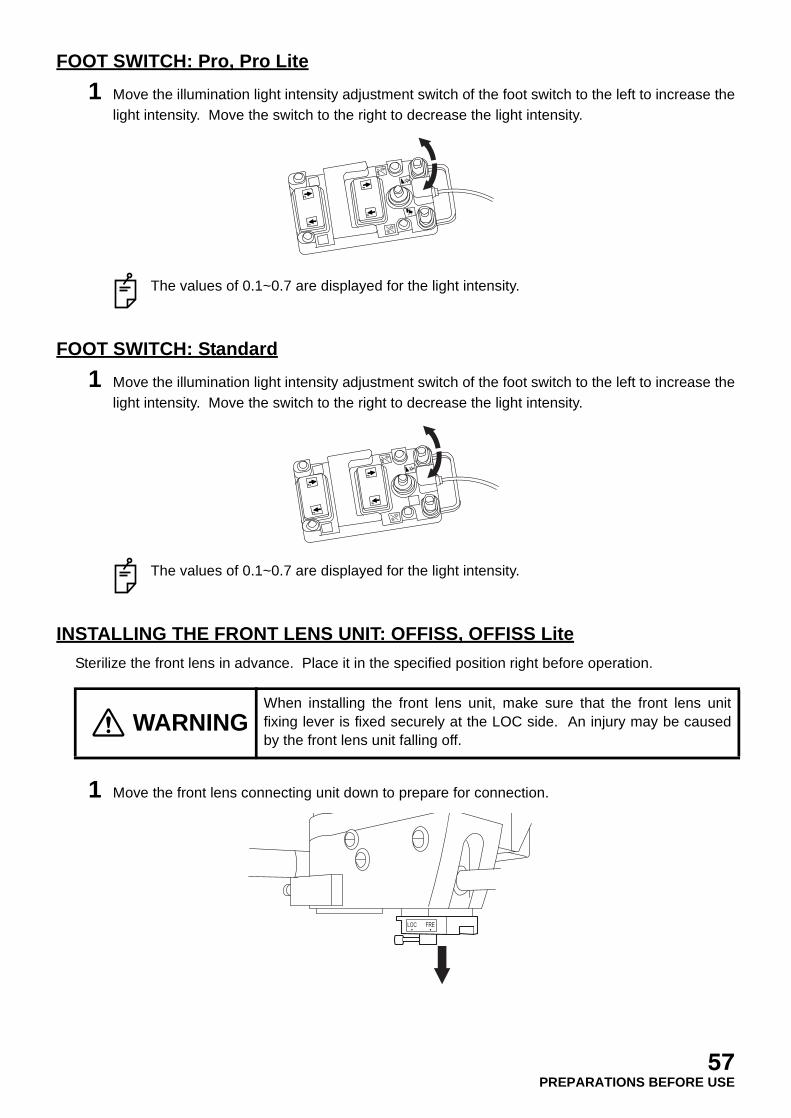
FOOT SWITCH: Pro, Pro Lite
1 Move the illumination light intensity adjustment switch of the foot switch to the left to increase thelight intensity. Move the switch to the right to decrease the light intensity.
The values of 0.1~0.7 are displayed for the light intensity.
FOOT SWITCH: Standard
1 Move the illumination light intensity adjustment switch of the foot switch to the left to increase thelight intensity. Move the switch to the right to decrease the light intensity.
The values of 0.1~0.7 are displayed for the light intensity.
INSTALLING THE FRONT LENS UNIT: OFFISS, OFFISS Lite
Sterilize the front lens in advance. Place it in the specified position right before operation.
1 Move the front lens connecting unit down to prepare for connection.
WARNINGWhen installing the front lens unit, make sure that the front lens unitfixing lever is fixed securely at the LOC side. An injury may be causedby the front lens unit falling off.
LOC FRE
57PREPARATIONS BEFORE USE
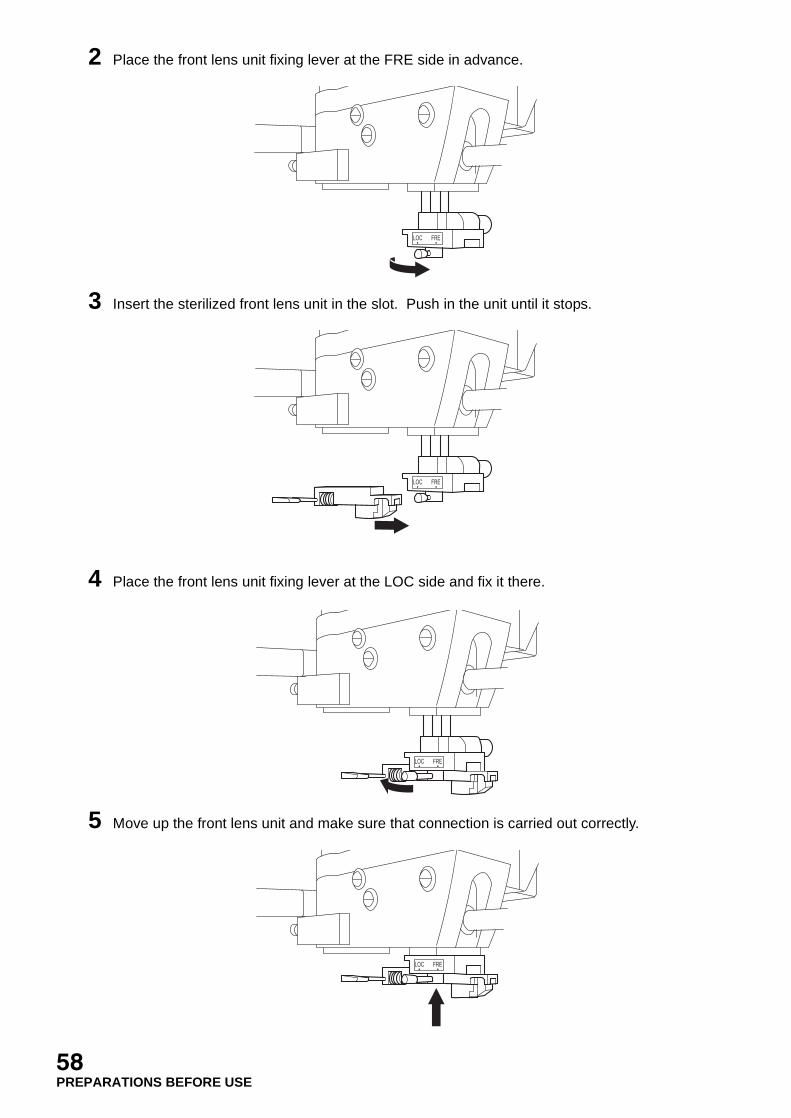
2 Place the front lens unit fixing lever at the FRE side in advance.
3 Insert the sterilized front lens unit in the slot. Push in the unit until it stops.
4 Place the front lens unit fixing lever at the LOC side and fix it there.
5 Move up the front lens unit and make sure that connection is carried out correctly.
LOC FRE
LOC FRE
LOC FRE
LOC FRE
58PREPARATIONS BEFORE USE
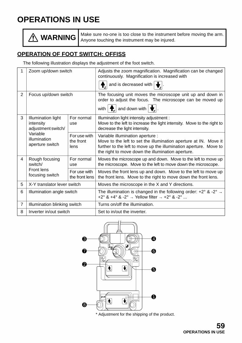
OPERATIONS IN USE
OPERATION OF FOOT SWITCH: OFFISS
The following illustration displays the adjustment of the foot switch.
WARNING Make sure no-one is too close to the instrument before moving the arm.Anyone touching the instrument may be injured.
1 Zoom up/down switch Adjusts the zoom magnification. Magnification can be changedcontinuously. Magnification is increased with
and is decreased with .
2 Focus up/down switch The focusing unit moves the microscope unit up and down inorder to adjust the focus. The microscope can be moved up
with and down with .
3 Illumination light intensity adjustment switch/ Variable illumination aperture switch
For normal use
Illumination light intensity adjustment : Move to the left to increase the light intensity. Move to the right todecrease the light intensity.
For use with the front lens
Variable illumination aperture : Move to the left to set the illumination aperture at IN. Move itfurther to the left to move up the illumination aperture. Move tothe right to move down the illumination aperture.
4 Rough focusing switch/Front lens focusing switch
For normal use
Moves the microscope up and down. Move to the left to move upthe microscope. Move to the left to move down the microscope.
For use with the front lens
Moves the front lens up and down. Move to the left to move upthe front lens. Move to the right to move down the front lens.
5 X-Y translator lever switch Moves the microscope in the X and Y directions.
6 Illumination angle switch The illumination is changed in the following order: +2° & -2° →+2° & +4° & -2° → Yellow filter → +2° & -2° ...
7 Illumination blinking switch Turns on/off the illumination.
8 Inverter in/out switch Set to in/out the inverter.
3
7
2
4
6
5
1
* Adjustment for the shipping of the product.
8
59OPERATIONS IN USE
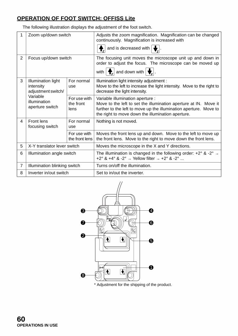
OPERATION OF FOOT SWITCH: OFFISS Lite
The following illustration displays the adjustment of the foot switch.
1 Zoom up/down switch Adjusts the zoom magnification. Magnification can be changedcontinuously. Magnification is increased with
and is decreased with .
2 Focus up/down switch The focusing unit moves the microscope unit up and down inorder to adjust the focus. The microscope can be moved up
with and down with .
3 Illumination light intensity adjustment switch/ Variable illumination aperture switch
For normal use
Illumination light intensity adjustment : Move to the left to increase the light intensity. Move to the right todecrease the light intensity.
For use with the front lens
Variable illumination aperture : Move to the left to set the illumination aperture at IN. Move itfurther to the left to move up the illumination aperture. Move tothe right to move down the illumination aperture.
4 Front lens focusing switch
For normal use
Nothing is not moved.
For use with the front lens
Moves the front lens up and down. Move to the left to move upthe front lens. Move to the right to move down the front lens.
5 X-Y translator lever switch Moves the microscope in the X and Y directions.
6 Illumination angle switch The illumination is changed in the following order: +2° & -2° →+2° & +4° & -2° → Yellow filter → +2° & -2° ...
7 Illumination blinking switch Turns on/off the illumination.
8 Inverter in/out switch Set to in/out the inverter.
3
7
2
4
6
5
1
* Adjustment for the shipping of the product.
8
60OPERATIONS IN USE

OPERATION OF FOOT SWITCH: Pro
The following illustration displays the adjustment of the foot switch.
1 Zoom up/down switch Adjusts the zoom magnification. Magnification can be changedcontinuously. Magnification is increased with
and is decreased with .
2 Focus up/down switch The focusing unit moves the microscope unit up and down inorder to adjust the focus. The microscope can be moved up with
and down with .
3 Illumination light intensity adjustment switch
Move to the left to increase the light intensity. Move to the right todecrease the light intensity.
4 Rough focusing switch Moves the microscope up and down. Move to the left to move upthe microscope. Move to the right to move down the microscope.
5 X-Y translator lever switch Moves the microscope in the X and Y directions.
6 Illumination angle switch The illumination is changed in the following order: +2° & -2° →+2° & +4° & -2° → Yellow filter → +2° & -2° ...
7 Illumination blinking switch Turns on/off the illumination.
3
7
2
4
6
5
1
* Adjustment for the shipping of the product.
61OPERATIONS IN USE
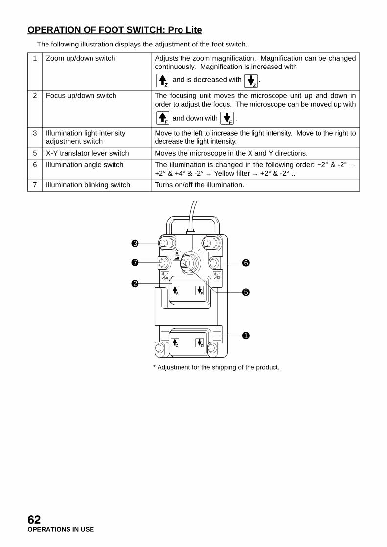
OPERATION OF FOOT SWITCH: Pro Lite
The following illustration displays the adjustment of the foot switch.
1 Zoom up/down switch Adjusts the zoom magnification. Magnification can be changedcontinuously. Magnification is increased with
and is decreased with .
2 Focus up/down switch The focusing unit moves the microscope unit up and down inorder to adjust the focus. The microscope can be moved up with
and down with .
3 Illumination light intensity adjustment switch
Move to the left to increase the light intensity. Move to the right todecrease the light intensity.
5 X-Y translator lever switch Moves the microscope in the X and Y directions.
6 Illumination angle switch The illumination is changed in the following order: +2° & -2° →+2° & +4° & -2° → Yellow filter → +2° & -2° ...
7 Illumination blinking switch Turns on/off the illumination.
3
7
2
6
5
1
* Adjustment for the shipping of the product.
62OPERATIONS IN USE

OPERATION OF FOOT SWITCH: Standard
The following illustration displays the adjustment of the foot switch.
1 Zoom up/down switch Adjusts the zoom magnification. Magnification can be changedcontinuously. Magnification is increased with
and is decreased with .
2 Focus up/down switch The focusing unit moves the microscope unit up and down inorder to adjust the focus. The microscope can be moved up with
and down with .
3 Illumination light intensity adjustment switch
Move to the left to increase the light intensity. Move to the right todecrease the light intensity.
5 X-Y translator lever switch Moves the microscope in the X and Y directions.
6 Illumination angle switch The illumination is changed in the following order: +2° & -2° →+2° & +4° & -2° → Yellow filter → +2° & -2° ...
7 Illumination blinking switch Turns on/off the illumination.
3
7
2
6
5
1
* Adjustment for the shipping of the product.
63OPERATIONS IN USE
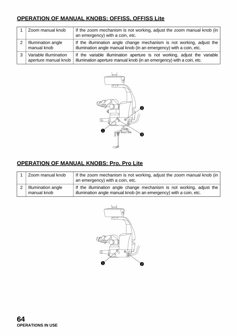
OPERATION OF MANUAL KNOBS: OFFISS, OFFISS Lite
OPERATION OF MANUAL KNOBS: Pro, Pro Lite
1 Zoom manual knob If the zoom mechanism is not working, adjust the zoom manual knob (inan emergency) with a coin, etc.
2 Illumination angle manual knob
If the illumination angle change mechanism is not working, adjust theillumination angle manual knob (in an emergency) with a coin, etc.
3 Variable illumination aperture manual knob
If the variable illumination aperture is not working, adjust the variableillumination aperture manual knob (in an emergency) with a coin, etc.
1 Zoom manual knob If the zoom mechanism is not working, adjust the zoom manual knob (inan emergency) with a coin, etc.
2 Illumination angle manual knob
If the illumination angle change mechanism is not working, adjust theillumination angle manual knob (in an emergency) with a coin, etc.
1
2
3
1 2
64OPERATIONS IN USE
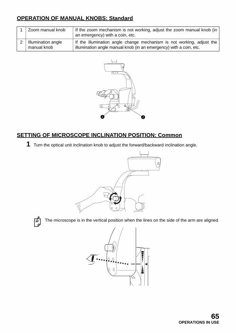
OPERATION OF MANUAL KNOBS: Standard
SETTING OF MICROSCOPE INCLINATION POSITION: Common
1 Turn the optical unit inclination knob to adjust the forward/backward inclination angle.
The microscope is in the vertical position when the lines on the side of the arm are aligned.
1 Zoom manual knob If the zoom mechanism is not working, adjust the zoom manual knob (inan emergency) with a coin, etc.
2 Illumination angle manual knob
If the illumination angle change mechanism is not working, adjust theillumination angle manual knob (in an emergency) with a coin, etc.
1 2
65OPERATIONS IN USE

SPEED ADJUSTMENT OF ZOOM/FOCUS/X-Y TRANSLATOR: Common
The zoom speed, focus speed and X-Y translator speed can be set individually.Each speed can be adjusted in five steps, 1~5.
1 Adjust the zoom speed with the zoom speed knob.
2 Adjust the focus speed with the focusing unit speed knob.
3 Adjust the X-Y translator speed with the X-Y translator speed knob.
EXIT
SPARE
MAIN
FOCUS XYZOOM
12 3 4
5 12 3 4
5 12 3 4
5
DOWNUP
EXIT
SPARE
MAIN
FOCUS XYZOOM
12 3 4
5 12 3 4
5 12 3 4
5
DOWNUP
EXIT
SPARE
MAIN
FOCUS XYZOOM
12 3 4
5 12 3 4
5 12 3 4
5
DOWNUP
66OPERATIONS IN USE

ADJUSTMENT OF FOCUS: OFFISS, OFFISS Lite, Pro, Pro Lite
The illustration displays the OFFISS type.
1 Hold the microscope operation handle and press the electromagnetic lock release switch. Thenroughly adjust the focus.
2 Adjust the focus up and down gently with the focus up/down switch of the foot switch to obtainthe correct focus.
ADJUSTMENT OF FOCUS: Standard
1 When loosening the 2nd arm vertical movement fixing handle, hold the microscope operationhandle and roughly adjust the focus. Then, tighten the 2nd arm vertical movement fixing handle.
2 Adjust the focus up and down gently with the focus up/down switch of the foot switch to obtainthe correct focus.
WARNINGBefore using this instrument, adjust the balance of the 2nd arm. The 2ndarm may move up and down suddenly during an operation, causing aninjury.
WARNINGBefore using this instrument, adjust the balance of the 2nd arm. The 2ndarm may move up and down suddenly during an operation, causing aninjury.
67OPERATIONS IN USE
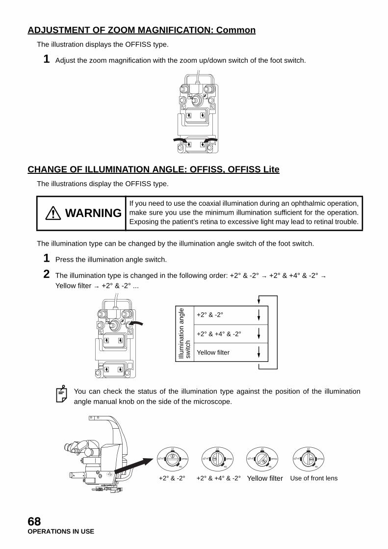
ADJUSTMENT OF ZOOM MAGNIFICATION: Common
The illustration displays the OFFISS type.
1 Adjust the zoom magnification with the zoom up/down switch of the foot switch.
CHANGE OF ILLUMINATION ANGLE: OFFISS, OFFISS Lite
The illustrations display the OFFISS type.
The illumination type can be changed by the illumination angle switch of the foot switch.
1 Press the illumination angle switch.
2 The illumination type is changed in the following order: +2° & -2° → +2° & +4° & -2° → Yellow filter → +2° & -2° ...
You can check the status of the illumination type against the position of the illuminationangle manual knob on the side of the microscope.
WARNINGIf you need to use the coaxial illumination during an ophthalmic operation,make sure you use the minimum illumination sufficient for the operation.Exposing the patient’s retina to excessive light may lead to retinal trouble.
Illum
inat
ion
angl
e sw
itch
+2° & -2°
+2° & +4° & -2°
Yellow filter
+2° & -2° +2° & +4° & -2° Yellow filter Use of front lens
68OPERATIONS IN USE
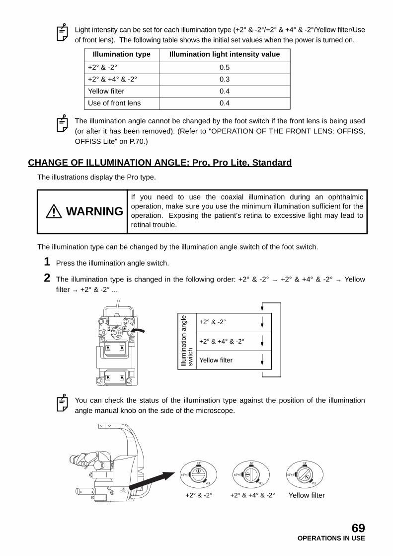
Light intensity can be set for each illumination type (+2° & -2°/+2° & +4° & -2°/Yellow filter/Useof front lens). The following table shows the initial set values when the power is turned on.
The illumination angle cannot be changed by the foot switch if the front lens is being used(or after it has been removed). (Refer to "OPERATION OF THE FRONT LENS: OFFISS,OFFISS Lite" on P.70.)
CHANGE OF ILLUMINATION ANGLE: Pro, Pro Lite, Standard
The illustrations display the Pro type.
The illumination type can be changed by the illumination angle switch of the foot switch.
1 Press the illumination angle switch.
2 The illumination type is changed in the following order: +2° & -2° → +2° & +4° & -2° → Yellowfilter → +2° & -2° ...
You can check the status of the illumination type against the position of the illuminationangle manual knob on the side of the microscope.
Illumination type Illumination light intensity value
+2° & -2° 0.5
+2° & +4° & -2° 0.3
Yellow filter 0.4
Use of front lens 0.4
WARNINGIf you need to use the coaxial illumination during an ophthalmicoperation, make sure you use the minimum illumination sufficient for theoperation. Exposing the patient’s retina to excessive light may lead toretinal trouble.
Illum
inat
ion
angl
e sw
itch
+2° & -2°
+2° & +4° & -2°
Yellow filter
+2° & -2° +2° & +4° & -2° Yellow filter
69OPERATIONS IN USE

Light intensity can be set for each illumination type (+2° & -2°/+2° & +4° & -2°/Yellow filter).The following table shows the initial set values when the power is turned on.
CHANGE OF SPECTRAL RATIO FOR BEAM SPLITTER: Common
• Only in the type with changeable beam splitter
1 Turn the spectral ratio knob or tilt the spectral ratio lever to the right or left, and the spectral ratiois changed.
OPERATION OF THE FRONT LENS: OFFISS, OFFISS Lite
The illustrations display the OFFISS type.
Illumination type Illumination light intensity value
+2° & -2° 0.5
+2° & +4° & -2° 0.3
Yellow filter 0.4
WARNINGHold the microscope operation handle while pressing theelectromagnetic lock release switch to unlock it. The arm may rotate ormove up and down suddenly, causing an injury.
WARNINGBefore setting the front lens, move the microscope at least 200mmupwards. Otherwise, the components may come into contact with eachother and cause an injury.
WARNING Adjust the front lens and the treatment section, taking care not to hit thepatient with the front lens. This could injure the patient.
WARNINGMake sure that the front lens unit is securely attached to the optical unitafter connecting the two. The front lens may move suddenly, causing aninjury.
WARNINGWhen setting/storing the front lens unit, make sure that the front lens unitfixing lever is fixed securely at the LOC side.An injury may be caused by the front lens unit falling off.
WARNINGBefore using this instrument, adjust the balance of the 2nd arm. The 2ndarm may move up and down suddenly during an operation, causing aninjury.
70OPERATIONS IN USE

Setting the front lens
1 Hold the microscope operation handle and press the electromagnetic lock release switch. Thenraise the microscope by approx. 200mm or more.
2 Turn the front lens IN/OUT lever clockwise to rotate the front lens toward the bottom of theobjective lens. Then, take out the front lens.
It is impossible to perform initialization (except X-Y translator) and to change the illuminationangle. The variable illumination aperture is used instead of the illumination light intensityadjustment of the foot switch, and the front lens fine movement unit is used instead of therough focusing unit. In OFFISS, the front lens fine movement unit is used instead of therough focusing unit. In OFFISS Lite, it is possible to operate the front lens fine movementunit.
When observing the eye ground through the front lens, the illumination angle and lightintensity are automatically changed to proper values.
The inverter is automatically set to IN and the IN indicator LED on its front surface lights up.
3 Turn the front lens connecting/disconnecting knob counterclockwise to move the front lensdownward.
71OPERATIONS IN USE
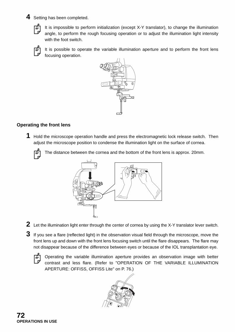
4 Setting has been completed.
It is impossible to perform initialization (except X-Y translator), to change the illuminationangle, to perform the rough focusing operation or to adjust the illumination light intensitywith the foot switch.
It is possible to operate the variable illumination aperture and to perform the front lensfocusing operation.
Operating the front lens
1 Hold the microscope operation handle and press the electromagnetic lock release switch. Thenadjust the microscope position to condense the illumination light on the surface of cornea.
The distance between the cornea and the bottom of the front lens is approx. 20mm.
2 Let the illumination light enter through the center of cornea by using the X-Y translator lever switch.
3 If you see a flare (reflected light) in the observation visual field through the microscope, move thefront lens up and down with the front lens focusing switch until the flare disappears. The flare maynot disappear because of the difference between eyes or because of the IOL transplantation eye.
Operating the variable illumination aperture provides an observation image with bettercontrast and less flare. (Refer to "OPERATION OF THE VARIABLE ILLUMINATIONAPERTURE: OFFISS, OFFISS Lite" on P. 76.)
72OPERATIONS IN USE
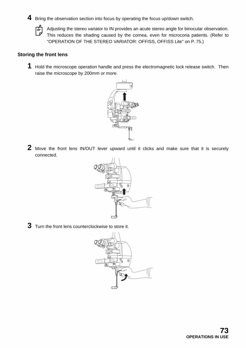
4 Bring the observation section into focus by operating the focus up/down switch.
Adjusting the stereo variator to IN provides an acute stereo angle for binocular observation.This reduces the shading caused by the cornea, even for microcoria patients. (Refer to"OPERATION OF THE STEREO VARIATOR: OFFISS, OFFISS Lite" on P. 75.)
Storing the front lens
1 Hold the microscope operation handle and press the electromagnetic lock release switch. Thenraise the microscope by 200mm or more.
2 Move the front lens IN/OUT lever upward until it clicks and make sure that it is securelyconnected.
3 Turn the front lens counterclockwise to store it.
73OPERATIONS IN USE
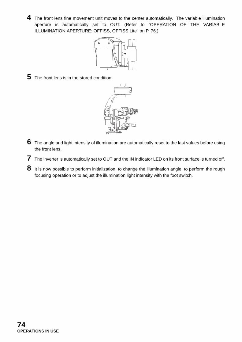
4 The front lens fine movement unit moves to the center automatically. The variable illuminationaperture is automatically set to OUT. (Refer to "OPERATION OF THE VARIABLEILLUMINATION APERTURE: OFFISS, OFFISS Lite" on P. 76.)
5 The front lens is in the stored condition.
6 The angle and light intensity of illumination are automatically reset to the last values before usingthe front lens.
7 The inverter is automatically set to OUT and the IN indicator LED on its front surface is turned off.
8 It is now possible to perform initialization, to change the illumination angle, to perform the roughfocusing operation or to adjust the illumination light intensity with the foot switch.
74OPERATIONS IN USE
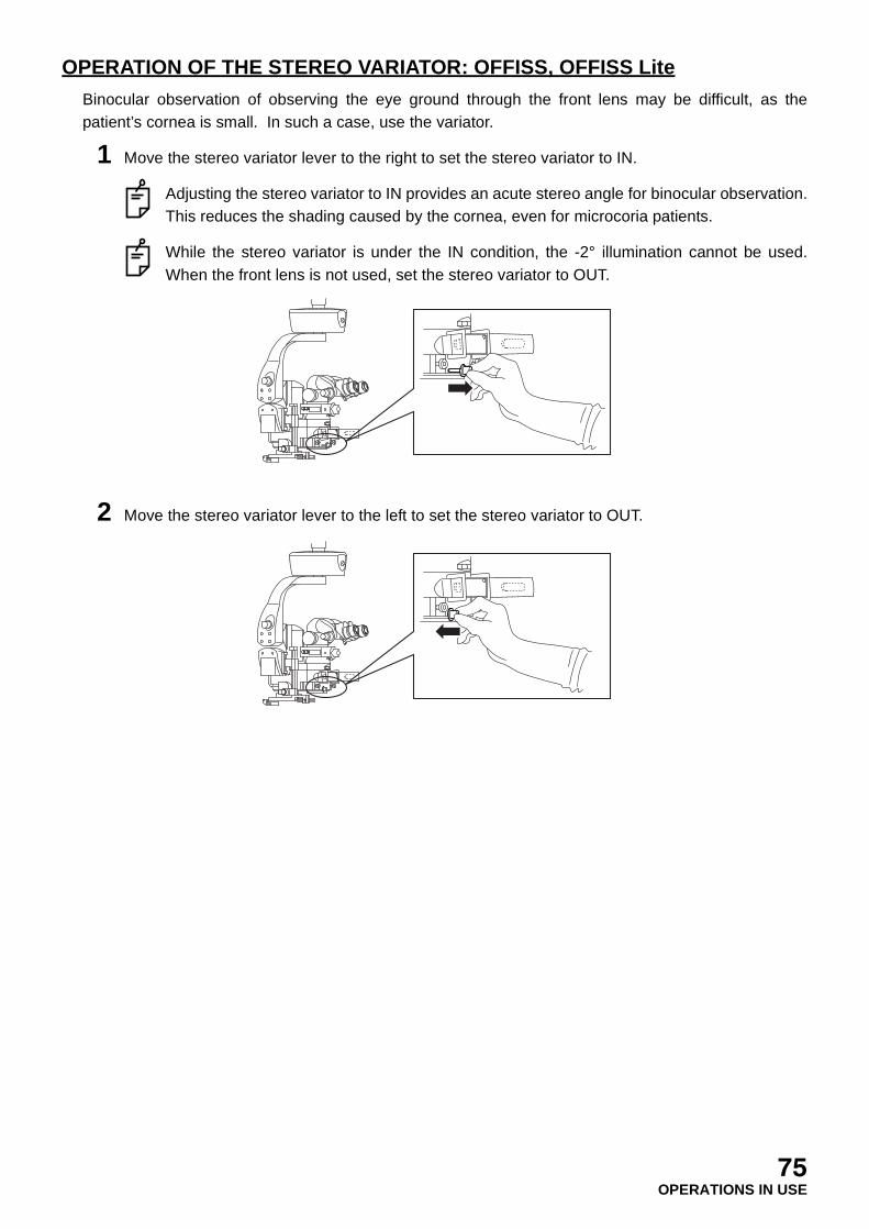
OPERATION OF THE STEREO VARIATOR: OFFISS, OFFISS Lite
Binocular observation of observing the eye ground through the front lens may be difficult, as thepatient’s cornea is small. In such a case, use the variator.
1 Move the stereo variator lever to the right to set the stereo variator to IN.
Adjusting the stereo variator to IN provides an acute stereo angle for binocular observation.This reduces the shading caused by the cornea, even for microcoria patients.
While the stereo variator is under the IN condition, the -2° illumination cannot be used.When the front lens is not used, set the stereo variator to OUT.
2 Move the stereo variator lever to the left to set the stereo variator to OUT.
75OPERATIONS IN USE
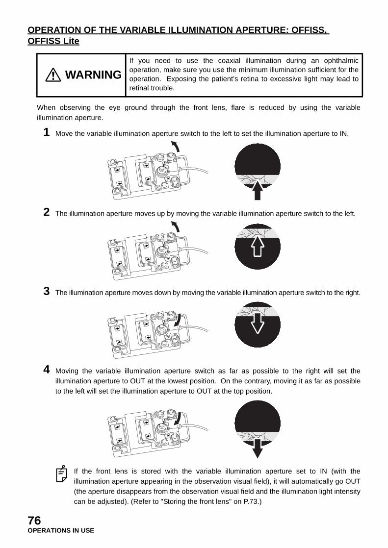
OPERATION OF THE VARIABLE ILLUMINATION APERTURE: OFFISS, OFFISS Lite
When observing the eye ground through the front lens, flare is reduced by using the variableillumination aperture.
1 Move the variable illumination aperture switch to the left to set the illumination aperture to IN.
2 The illumination aperture moves up by moving the variable illumination aperture switch to the left.
3 The illumination aperture moves down by moving the variable illumination aperture switch to the right.
4 Moving the variable illumination aperture switch as far as possible to the right will set theillumination aperture to OUT at the lowest position. On the contrary, moving it as far as possibleto the left will set the illumination aperture to OUT at the top position.
If the front lens is stored with the variable illumination aperture set to IN (with theillumination aperture appearing in the observation visual field), it will automatically go OUT(the aperture disappears from the observation visual field and the illumination light intensitycan be adjusted). (Refer to "Storing the front lens" on P.73.)
WARNINGIf you need to use the coaxial illumination during an ophthalmicoperation, make sure you use the minimum illumination sufficient for theoperation. Exposing the patient’s retina to excessive light may lead toretinal trouble.
76OPERATIONS IN USE
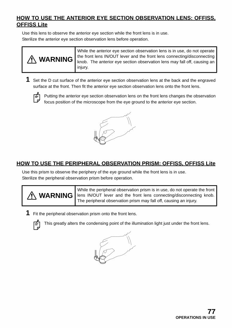
HOW TO USE THE ANTERIOR EYE SECTION OBSERVATION LENS: OFFISS,OFFISS Lite
Use this lens to observe the anterior eye section while the front lens is in use.Sterilize the anterior eye section observation lens before operation.
1 Set the D cut surface of the anterior eye section observation lens at the back and the engravedsurface at the front. Then fit the anterior eye section observation lens onto the front lens.
Putting the anterior eye section observation lens on the front lens changes the observationfocus position of the microscope from the eye ground to the anterior eye section.
HOW TO USE THE PERIPHERAL OBSERVATION PRISM: OFFISS, OFFISS Lite
Use this prism to observe the periphery of the eye ground while the front lens is in use.Sterilize the peripheral observation prism before operation.
1 Fit the peripheral observation prism onto the front lens.
This greatly alters the condensing point of the illumination light just under the front lens.
WARNINGWhile the anterior eye section observation lens is in use, do not operatethe front lens IN/OUT lever and the front lens connecting/disconnectingknob. The anterior eye section observation lens may fall off, causing aninjury.
WARNINGWhile the peripheral observation prism is in use, do not operate the frontlens IN/OUT lever and the front lens connecting/disconnecting knob.The peripheral observation prism may fall off, causing an injury.
77OPERATIONS IN USE

2 Turn the peripheral observation prism so that its slope surface direction is opposite to thedirection of the periphery to be observed.
Turning the peripheral observation prism greatly alters the condensing point of theillumination light emitted from the front lens.
3 Move the microscope horizontally with the X-Y translator so that the condensing point of theillumination light emitted from the front lens is aimed at the pupil of the patient's eye.
For safety’s sake, carry out the above adjustment watching the patient’s eye directly,without using the microscope.
4 While watching the patient's eye through the microscope, remove flare (fine movement of thefront lens) and perform focusing (focus up/down switch operation).
5 When you change the position of the periphery to be observed, also perform the above 2 ~ 4.
OPERATION OF INVERTER: OFFISS, OFFISS Lite
You can set the inverter to IN/OUT with the inverter in/out switch of the foot switch regardless of thefront lens status.
1 Press the inverter in/out switch of the foot switch.
2 Each time the switch is pressed, the IN/OUT change is repeated. The IN indicator LED lights upfor the inverter IN status and switches off for its OUT status.
R
R
78OPERATIONS IN USE

REPLACING WITH THE SPARE LAMP: Common
If the illumination lamp has burned out during operation, the spare lamp can be fitted easily by rotatingthe lamp house unit.
If either "LAMP A" or "LAMP B" has burned out, replace it with a new one. (Refer to"REPLACEMENT OF THE SPARE LAMP" on P.97 and "CONSUMABLE PARTS" on P.89~P.90.)
WARNING Use only the specified lamp. Otherwise, overheating may cause a fire.
CAUTIONHandle the lamp house with care during and immediately followingoperation. The lamp house heats up while in operation and can causeburns.
CAUTION Do not open the instrument, as this may lead to an electric shock.
NOTE Ask your distributor or the Topcon offices stated on the back cover to repair theinstrument.
79OPERATIONS IN USE
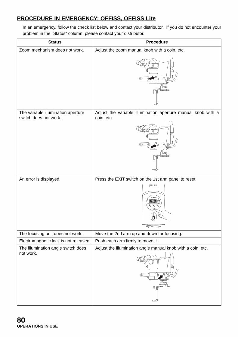
PROCEDURE IN EMERGENCY: OFFISS, OFFISS Lite
In an emergency, follow the check list below and contact your distributor. If you do not encounter yourproblem in the "Status" column, please contact your distributor.
Status Procedure
Zoom mechanism does not work. Adjust the zoom manual knob with a coin, etc.
The variable illumination aperture switch does not work.
Adjust the variable illumination aperture manual knob with acoin, etc.
An error is displayed. Press the EXIT switch on the 1st arm panel to reset.
The focusing unit does not work. Move the 2nd arm up and down for focusing.
Electromagnetic lock is not released. Push each arm firmly to move it.
The illumination angle switch does not work.
Adjust the illumination angle manual knob with a coin, etc.
EXIT
SPARE
MAIN
FOCUS XYZOOM
12 3 4
5 12 3 4
5 12 3 4
5
80OPERATIONS IN USE

PROCEDURE IN EMERGENCY: Pro, Pro Lite
In an emergency, follow the check list below and contact your distributor. If you do not encounter yourproblem in the "Status" column, please contact your distributor.
The inverter does not work. The manual IN/OUT knob (with sterilized cap) is located on thefront of the inverter. Turn this knob clockwise to the “click”position.
Status Procedure
Zoom mechanism does not work. Adjust the zoom manual knob with a coin, etc.
An error is displayed. Press the EXIT switch on the 1st arm panel to reset.
The focusing unit does not work. Move the 2nd arm up and down for focusing.
Electromagnetic lock is not released. Push each arm firmly to move it.
The illumination angle switch does not work.
Adjust the illumination angle manual knob with a coin, etc.
Status Procedure
EXIT
SPARE
MAIN
FOCUS XYZOOM
12 3 4
5 12 3 4
5 12 3 4
5
81OPERATIONS IN USE

PROCEDURE IN EMERGENCY: Standard
In an emergency, follow the check list below and contact your distributor. If you do not encounter yourproblem in the "Status" column, please contact your distributor.
Status Procedure
Zoom mechanism does not work. Adjust the zoom manual knob with a coin, etc.
An error is displayed. Press the EXIT switch on the 1st arm panel to reset.
The focusing unit does not work. Move the 2nd arm up and down for focusing.
The illumination angle switch does not work.
Adjust the illumination angle manual knob with a coin, etc.
EXIT
SPARE
MAIN
FOCUS XYZOOM
12 3 4
5 12 3 4
5 12 3 4
5
82OPERATIONS IN USE

AFTER USE
AFTER USE: Common
1 Turn off the power switch.
2 Remove the power plug from the power outlet.
3 Carry out cleaning.
Refer to "CLEANING THE OBJECTIVE LENS / THE EYEPIECE LENS" on P.101.
Refer to “CLEANING THE FRONT LENS STORING UNIT” on P.101.
Refer to "CLEANING OTHERS EXCEPT OPTICAL SYSTEM" on P.102.
MOVING AND STORING: OFFISS, OFFISS Lite, Pro, Pro Lite
WARNING Make sure no-one is too close to the instrument before moving the arm.Anyone touching the instrument may be injured.
WARNINGBefore moving the instrument, make sure that no-one is near. Then,move it carefully. Injury could be caused by the instrument touchinganything.
WARNINGHold the microscope operation handle while pressing theelectromagnetic lock release switch to unlock it. The arm may rotate ormove up and down suddenly, causing an injury.
CAUTIONTake care when moving this instrument through a door or in a room witha low ceiling. If the top of this instrument collides with something, it couldbreak.
CAUTION Watch out for devices, beds, walls, etc. in the room. If the instrumentcollides with anything, serious breakage could result.
CAUTION Watch out for stairs and uneven floors. This instrument may tip over.
CAUTION Watch out for slopes. Due to its increased speed, the instrument mayget away from you on a slope.
CAUTION Do not install this instrument on an incline. This may cause it to moveunexpectedly.
83AFTER USE / MOVING AND STORING: OFFISS OFFISS Lite, Pro, Pro Lite

Please carry out the following procedures for the moving and storing of this instrument.
1 Connect the power plug to the power outlet.
2 Turn on the power switch.
3 Press the electromagnetic lock release switch and move the 1st and 2nd arms so as not tohinder storing.
The 2nd arm can be fixed at the lower limit position by setting the 2nd arm lower limit lock.(Refer to "LOCKING/UNLOCKING THE 2ND ARM LOWER LIMIT: OFFISS, OFFISS Lite,Pro, Pro Lite" on P.48.)
4 Turn off the power switch.
5 Remove the power plug from the power outlet.
6 Hang the foot switch on the foot switch hanger.
7 Hang the foot switch cord and the power cord on the cord hanger.
8 Raise the caster lock lever to unlock.
EXIT
SPARE
MAIN
FOCUS XYZOOM
12 3 4
5 12 3 4
5 12 3 4
5
EXIT
SPARE
MAIN
FOCUS XYZOOM
12 3 4
5 12 3 4
5 12 3 4
5
84MOVING AND STORING: OFFISS, OFFISS Lite, Pro, Pro Lite

9 Hold the base movement handle and move the instrument gently.
10 Lower the caster lock lever to lock it when reaching the destination or storing place.
MOVING AND STORING: Standard
Please carry out the following procedures when moving and storing this instrument.
1 Loosen the 2nd arm vertical movement fixing handle, the 2nd arm rotation fixing handle and the1st arm rotation fixing handle. Move the 1st and 2nd arms so as not to hinder storing and thentighten and fix them.
The 2nd arm can be fixed at the lower limit position by setting the 2nd arm lower limit lock.(Refer to "LOCKING/UNLOCKING THE 2ND ARM LOWER LIMIT: Standard" on P.50.)
WARNINGBefore moving the instrument, make sure that no-one is near. Then,move it carefully. Injury could be caused by the instrument touchinganything.
WARNINGAlways hold the microscope operation handle when loosening either the2nd arm vertical movement fixing handle, the 2nd arm rotation fixinghandle or the 1st arm rotation fixing handle. The arm may rotate or moveup and down suddenly, causing an injury.
CAUTIONTake care when moving this instrument through a door or in a room witha low ceiling. If the top of this instrument collides with something, it couldbreak.
CAUTION Watch out for devices, beds, walls, etc. in the room. If the instrumentcollides with anything, serious breakage could result.
CAUTION Watch out for stairs and uneven floors. This instrument may tip over.
CAUTION Watch out for slopes. Due to its increased speed, the instrument mayget away from you on a slope.
CAUTION Do not install this instrument on an incline. This may cause it to moveunexpectedly.
85MOVING AND STORING: OFFISS, OFFISS Lite, Pro, Pro Lite / MOVING AND STORING: Standard

2 Hang the foot switch on the foot switch hanger.
3 Hang the foot switch cord and the power cord on the cord hanger.
4 Raise the caster lock lever to unlock.
5 Hold the base movement handle and move the instrument gently.
6 Lower the caster lock lever to lock it when reaching the destination or storing place.
86MOVING AND STORING: Standard
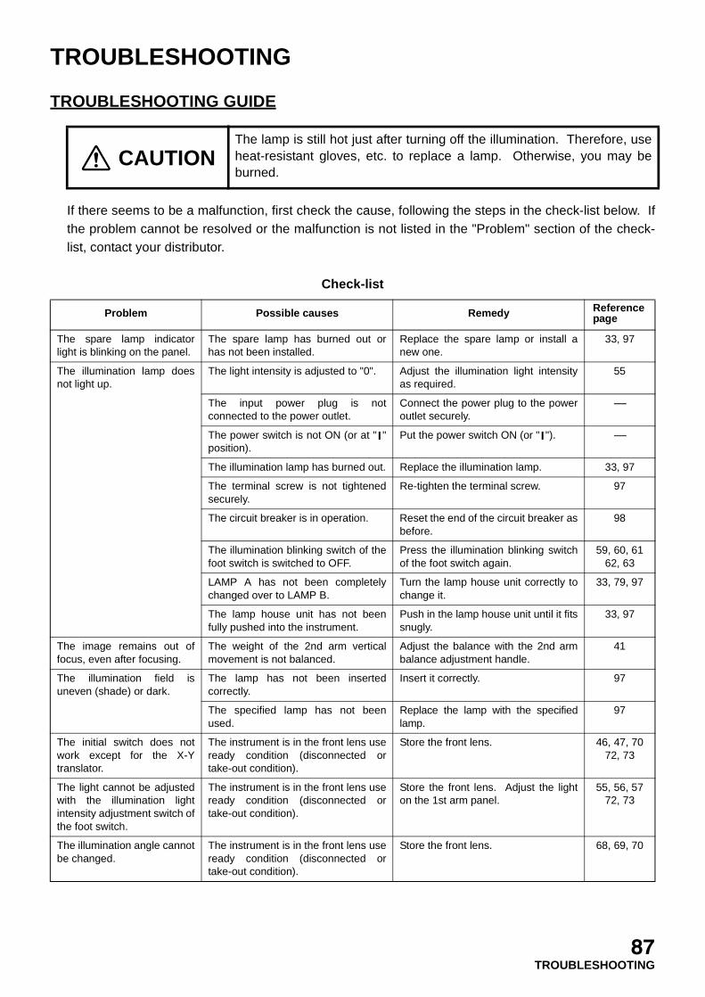
TROUBLESHOOTING
TROUBLESHOOTING GUIDE
If there seems to be a malfunction, first check the cause, following the steps in the check-list below. Ifthe problem cannot be resolved or the malfunction is not listed in the "Problem" section of the check-list, contact your distributor.
Check-list
CAUTIONThe lamp is still hot just after turning off the illumination. Therefore, useheat-resistant gloves, etc. to replace a lamp. Otherwise, you may beburned.
Problem Possible causes Remedy Reference page
The spare lamp indicatorlight is blinking on the panel.
The spare lamp has burned out orhas not been installed.
Replace the spare lamp or install anew one.
33, 97
The illumination lamp doesnot light up.
The light intensity is adjusted to "0". Adjust the illumination light intensityas required.
55
The input power plug is notconnected to the power outlet.
Connect the power plug to the poweroutlet securely.
-----
The power switch is not ON (or at " "position).
Put the power switch ON (or " "). -----
The illumination lamp has burned out. Replace the illumination lamp. 33, 97
The terminal screw is not tightenedsecurely.
Re-tighten the terminal screw. 97
The circuit breaker is in operation. Reset the end of the circuit breaker asbefore.
98
The illumination blinking switch of thefoot switch is switched to OFF.
Press the illumination blinking switchof the foot switch again.
59, 60, 6162, 63
LAMP A has not been completelychanged over to LAMP B.
Turn the lamp house unit correctly tochange it.
33, 79, 97
The lamp house unit has not beenfully pushed into the instrument.
Push in the lamp house unit until it fitssnugly.
33, 97
The image remains out offocus, even after focusing.
The weight of the 2nd arm verticalmovement is not balanced.
Adjust the balance with the 2nd armbalance adjustment handle.
41
The illumination field isuneven (shade) or dark.
The lamp has not been insertedcorrectly.
Insert it correctly. 97
The specified lamp has not beenused.
Replace the lamp with the specifiedlamp.
97
The initial switch does notwork except for the X-Ytranslator.
The instrument is in the front lens useready condition (disconnected ortake-out condition).
Store the front lens. 46, 47, 7072, 73
The light cannot be adjustedwith the illumination lightintensity adjustment switch ofthe foot switch.
The instrument is in the front lens useready condition (disconnected ortake-out condition).
Store the front lens. Adjust the lighton the 1st arm panel.
55, 56, 5772, 73
The illumination angle cannotbe changed.
The instrument is in the front lens useready condition (disconnected ortake-out condition).
Store the front lens. 68, 69, 70
87TROUBLESHOOTING

ERROR CODES
1 Press the EXIT switch on the panel, and the error code is canceled.
An error code is canceled by pressing the EXIT switch. Write the error details of the error codeand contact your distributor.
Code Error Cause Remedy
E1 Centering error "NG" of centering is detected for one ofZOOM, FOCUS and vertical roughmovement.
OFFISSPro
Press the EXIT switch on the panel.
"NG" of centering is detected for ZOOMor FOCUS.
Standard
E2 Illumination angle changing error
Zero position detection error ofillumination angle change
OFFISSProStandard
E4 Front lens initializing error
"NG" of initializing is detected for frontlens fine movement or variableillumination aperture.
OFFISS
Press the EXIT switch on the panel.
EP EEPROM error Data reading of EEPROM is not good. OFFISSProStandard
LP Lamp house error The lamp position detection switch is notfunctioning properly or the lamp househas not been set correctly.
OFFISSProStandard
FE Fan error The fan has stopped. If the instrumentcontinues to operate after the fan hasstopped, the power supply maymalfunction within about 1 hour.
OFFISSProStandard
EXIT
SPARE
MAIN
FOCUS XYZOOM
12 3 4
5 12 3 4
5 12 3 4
5
88TROUBLESHOOTING

CONSUMABLE PARTS: OFFISS, OFFISS Lite
The sterilized cap and the specified lamp are consumable parts. Order them from your distributor orthe Topcon offices stated on the back cover.
* and are attached to only the type equipped with the changeable beam splitter.
CONSUMABLE PARTS: Pro, Pro Lite
The sterilized cap and the specified lamp are consumable parts. Order them from your distributor orthe Topcon offices stated on the back cover.
* and are attached to only the type equipped with the changeable beam splitter.
Sterilized cap Q’ty Parts No.
Type A
Optical unit inclination knob 1
455201059
Pupillary distance adjustmentknob
2
Front lens connecting/disconnecting knob
1
Spectral ratio knob of changeablebeam splitter
1
Type B Microscope operation handle 2 455464004
Type C
Observation angle handle 1
457951018
Stereo variator lever 1
Front lens unit fixing lever 1
Spectral ratio lever of changeablebeam splitter
1
Lamp Parts No.
Halogen lamp, 12V, 100W, Philips Type 6834 Lamp456254021Socket4562671200
Sterilized cap Q’ty Parts No.
Type A
Optical unit inclination knob 1
455201059Pupillary distance adjustmentknob
2
Spectral ratio knob of changeablebeam splitter
1
Type B Microscope operation handle 2 455464004
Type C
Observation angle handle 1
457951018Spectral ratio lever of changeablebeam splitter
1
Lamp Parts No.
Halogen lamp, 12V, 100W, Philips Type 6834 Lamp456254021Socket4562671200
4
2
1
3
5
6
7
Type with changeablebeam splitter
8
9
1
2
6
8
3
4
5
7
9
8 9
1
2
4
3Type with changeablebeam splitter
8
9
1
2
8
3
4
9
8 9
89TROUBLESHOOTING

CONSUMABLE PARTS: Standard
The sterilized cap and the specified lamp are consumable parts. Order them from your distributor orthe Topcon offices stated on the back cover.
* and are attached to only the type equipped with the changeable beam splitter.
Sterilized cap Q’ty Parts No.
Type A
Optical unit inclination knob 1
455201059Pupillary distance adjustmentknob
2
Spectral ratio knob of changeablebeam splitter
1
Type B Microscope operation handle 2 455464004
Type C
Observation angle handle 1
457951018Spectral ratio lever of changeablebeam splitter
1
Lamp Parts No.
Halogen lamp, 12V, 100W, Philips Type 6834 Lamp456254021Socket4562671200
1
2
4
3 Type with changeablebeam splitter
8
9
1
2
8
3
4
9
8 9
90TROUBLESHOOTING
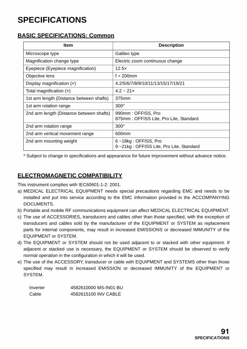
SPECIFICATIONS
BASIC SPECIFICATIONS: Common
* Subject to change in specifications and appearance for future improvement without advance notice.
ELECTROMAGNETIC COMPATIBILITY
This instrument complies with IEC60601-1-2: 2001.a) MEDICAL ELECTRICAL EQUIPMENT needs special precautions regarding EMC and needs to be
installed and put into service according to the EMC information provided in the ACCOMPANYINGDOCUMENTS.
b) Portable and mobile RF communications equipment can affect MEDICAL ELECTRICAL EQUIPMENT.c) The use of ACCESSORIES, transducers and cables other than those specified, with the exception of
transducers and cables sold by the manufacturer of the EQUIPMENT or SYSTEM as replacementparts for internal components, may result in increased EMISSIONS or decreased IMMUNITY of theEQUIPMENT or SYSTEM.
d) The EQUIPMENT or SYSTEM should not be used adjacent to or stacked with other equipment. Ifadjacent or stacked use is necessary, the EQUIPMENT or SYSTEM should be observed to verifynormal operation in the configuration in which it will be used.
e) The use of the ACCESSORY, transducer or cable with EQUIPMENT and SYSTEMS other than thosespecified may result in increased EMISSION or decreased IMMUNITY of the EQUIPMENT orSYSTEM.
Inverter 4582610000 MS-IN01-BUCable 4582615100 INV CABLE
Item Description
Microscope type Galileo type
Magnification change type Electric zoom continuous change
Eyepiece (Eyepiece magnification) 12.5×
Objective lens f = 200mm
Display magnification (×) 4.2/5/6/7/8/9/10/11/13/15/17/19/21
Total magnification (×) 4.2 ~ 21×
1st arm length (Distance between shafts) 375mm
1st arm rotation range 300°
2nd arm length (Distance between shafts) 990mm : OFFISS, Pro875mm : OFFISS Lite, Pro Lite, Standard
2nd arm rotation range 300°
2nd arm vertical movement range 600mm
2nd arm mounting weight 6 ~18kg : OFFISS, Pro9 ~21kg : OFFISS Lite, Pro Lite, Standard
91SPECIFICATIONS
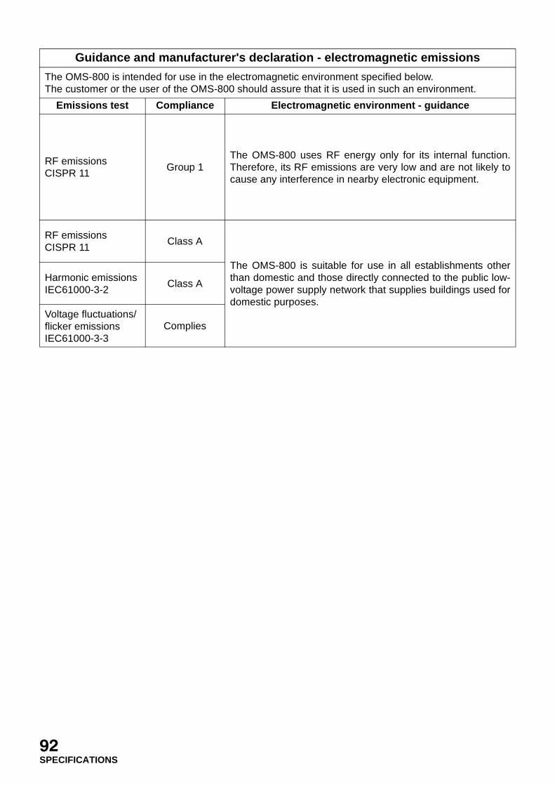
Guidance and manufacturer's declaration - electromagnetic emissions
The OMS-800 is intended for use in the electromagnetic environment specified below.The customer or the user of the OMS-800 should assure that it is used in such an environment.
Emissions test Compliance Electromagnetic environment - guidance
RF emissionsCISPR 11
Group 1The OMS-800 uses RF energy only for its internal function.Therefore, its RF emissions are very low and are not likely tocause any interference in nearby electronic equipment.
RF emissionsCISPR 11
Class A
The OMS-800 is suitable for use in all establishments otherthan domestic and those directly connected to the public low-voltage power supply network that supplies buildings used fordomestic purposes.
Harmonic emissionsIEC61000-3-2
Class A
Voltage fluctuations/flicker emissionsIEC61000-3-3
Complies
92SPECIFICATIONS
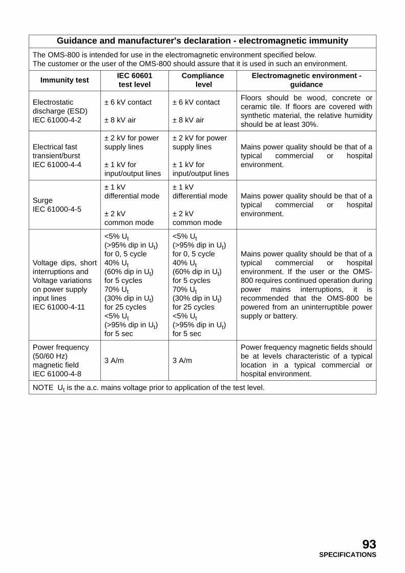
Guidance and manufacturer's declaration - electromagnetic immunity
The OMS-800 is intended for use in the electromagnetic environment specified below.The customer or the user of the OMS-800 should assure that it is used in such an environment.
Immunity test IEC 60601test level
Compliance level
Electromagnetic environment - guidance
Electrostaticdischarge (ESD)IEC 61000-4-2
± 6 kV contact
± 8 kV air
± 6 kV contact
± 8 kV air
Floors should be wood, concrete orceramic tile. If floors are covered withsynthetic material, the relative humidityshould be at least 30%.
Electrical fasttransient/burstIEC 61000-4-4
± 2 kV for powersupply lines
± 1 kV forinput/output lines
± 2 kV for powersupply lines
± 1 kV forinput/output lines
Mains power quality should be that of atypical commercial or hospitalenvironment.
SurgeIEC 61000-4-5
± 1 kVdifferential mode
± 2 kVcommon mode
± 1 kVdifferential mode
± 2 kVcommon mode
Mains power quality should be that of atypical commercial or hospitalenvironment.
Voltage dips, shortinterruptions andVoltage variationson power supplyinput linesIEC 61000-4-11
<5% Ut(>95% dip in Ut)for 0, 5 cycle40% Ut(60% dip in Ut)for 5 cycles70% Ut(30% dip in Ut)for 25 cycles<5% Ut(>95% dip in Ut)for 5 sec
<5% Ut(>95% dip in Ut)for 0, 5 cycle40% Ut(60% dip in Ut)for 5 cycles70% Ut(30% dip in Ut)for 25 cycles<5% Ut(>95% dip in Ut)for 5 sec
Mains power quality should be that of atypical commercial or hospitalenvironment. If the user or the OMS-800 requires continued operation duringpower mains interruptions, it isrecommended that the OMS-800 bepowered from an uninterruptible powersupply or battery.
Power frequency(50/60 Hz)magnetic fieldIEC 61000-4-8
3 A/m 3 A/m
Power frequency magnetic fields shouldbe at levels characteristic of a typicallocation in a typical commercial orhospital environment.
NOTE Ut is the a.c. mains voltage prior to application of the test level.
93SPECIFICATIONS
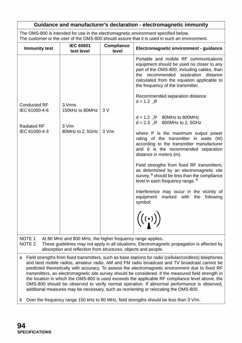
Guidance and manufacturer's declaration - electromagnetic immunity
The OMS-800 is intended for use in the electromagnetic environment specified below.The customer or the user of the OMS-800 should assure that it is used in such an environment.
Immunity test IEC 60601test level
Compliance level
Electromagnetic environment - guidance
Conducted RFIEC 61000-4-6
Radiated RFIEC 61000-4-3
3 Vrms150kHz to 80MHz
3 V/m80MHz to 2, 5GHz
3 V
3 V/m
Portable and mobile RF communicationsequipment should be used no closer to anypart of the OMS-800, including cables, thanthe recommended separation distancecalculated from the equation applicable tothe frequency of the transmitter.
Recommended separation distanced = 1.2
d = 1.2 80MHz to 800MHzd = 2.3 800MHz to 2, 5GHz
where P is the maximum output powerrating of the transmitter in watts (W)according to the transmitter manufacturerand d is the recommended separationdistance in meters (m).
Field strengths from fixed RF transmitters,as determined by an electromagnetic sitesurvey, a should be less than the compliancelevel in each frequency range. b
Interference may occur in the vicinity ofequipment marked with the followingsymbol:
NOTE 1NOTE 2
At 80 MHz and 800 MHz, the higher frequency range applies.These guidelines may not apply in all situations. Electromagnetic propagation is affected byabsorption and reflection from structures, objects and people.
a
b
Field strengths from fixed transmitters, such as base stations for radio (cellular/cordless) telephonesand land mobile radios, amateur radio, AM and FM radio broadcast and TV broadcast cannot bepredicted theoretically with accuracy. To assess the electromagnetic environment due to fixed RFtransmitters, an electromagnetic site survey should be considered. If the measured field strength inthe location in which the OMS-800 is used exceeds the applicable RF compliance level above, theOMS-800 should be observed to verify normal operation. If abnormal performance is observed,additional measures may be necessary, such as reorienting or relocating the OMS-800.
Over the frequency range 150 kHz to 80 MHz, field strengths should be less than 3 V/m.
P
PP
94SPECIFICATIONS

ELECTRIC RATING
Power supply voltage : AC100V~120V, 220~240V, 50/60HzPower supply input : 280VA
CLASSIFICATION
• The type of protection against electric shock: Class I equipmentThis instrument is classified as Class I. Class I equipment does not depend only on basic insulationagainst electric shock. It contains a mechanism that connects with the protective grounding systemof the facilities, so that the metal parts with which you come into contact cannot electrify you if thebasic insulation malfunctions.
• The degree of protection against water damage: IPX0 (Main body), IPX8 (Foot switch)• The mode of operation: Continuous operation
Recommended separation distance betweenportable and mobile RF communications equipment and the OMS-800
The OMS-800 is intended for use in an electromagnetic environment in which radiated RF disturbancesare controlled. The customer or the user of the OMS-800 can help prevent electromagnetic interferenceby maintaining a minimum distance between portable and mobile RF communications equipment(transmitters) and the OMS-800 as recommended below, according to the maximum output power ofthe communications equipment.
Rated maximum output power of transmitter
W
Separation distance according to frequency of transmitterm
150kHz to 80MHzd = 1.2
80MHz to 800MHzd = 1.2
800MHz to 2,5GHzd = 2.3
0, 01 0, 12 0, 12 0, 23
0, 1 0, 38 0, 38 0, 73
1 1.2 1.2 2.3
10 3.8 3.8 7.3
100 12 12 23
For transmitters rated at a maximum output power not listed above, the recommended separationdistance d in metres (m) can be estimated using the equation applicable to the frequency of thetransmitter, where P is the maximum output power rating of the transmitter in watts (W) according to thetransmitter manufacturer.
NOTE 1NOTE 2
At 80 MHz and 800 MHz, the separation distance for the higher frequency range applies.These guidelines may not apply in all situations. Electromagnetic propagation is affected byabsorption and reflection from structures, objects and people.
P P P
95SPECIFICATIONS

DIMENSIONS AND WEIGHT
Dimensions: Base (Base unit): 715 (W) × 715mm (D)Base (Total height): 1,865mm
Weight: 250kg: OFFISS247kg: OFFISS Lite247kg: Pro244kg: Pro Lite244kg: Standard
PURPOSE OF USE
Microscope to be used for operation, treatment or observation
OPERATION PRINCIPLE
The illuminator lights the section to be observed. The binocular real-image microscope magnifies thesection to enable observation.
96SPECIFICATIONS

MAINTENANCE AND INSPECTION: Common
REPLACEMENT OF THE SPARE LAMP
Use the spare lamp to replace a burned-out lamp after operation following the steps below.If LAMP A or LAMP B has burned out, replace the burned-out lamp with a new one followingthe steps below.
1 Turn off ( ) the power switch.
2 Turn the lamp house unit and set it at the position. Then pull the lamp house unit forward.
3 The lamp house unit has two lamps ( and ). Remove the terminal screws and terminal cord fromsocket of the burned-out lamp.
WARNING Use only the specified lamp. Otherwise, overheating may cause a fire.
CAUTIONHandle the lamp house with care during and immediately followingoperation. The lamp house heats up while in operation and can cause burns.
CAUTIONThe lamp is still hot just after turning off the illumination. Therefore, useheat-resistant gloves, etc. to replace a lamp. Otherwise, you may beburned.
NOTE Turn the lamp house unit until it stops with a "Click".
EXIT
SPARE
MAIN
FOCUS XYZOOM
12 3 4
5 12 3 4
5 12 3 4
5
97MAINTENANCE AND INSPECTION: Common
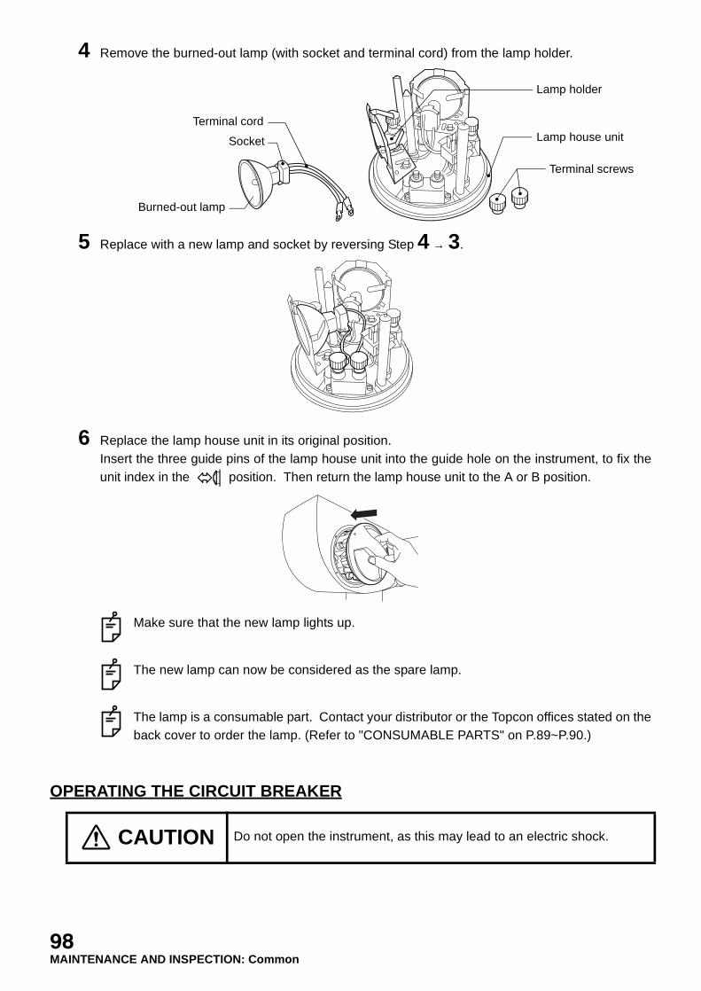
4 Remove the burned-out lamp (with socket and terminal cord) from the lamp holder.
5 Replace with a new lamp and socket by reversing Step 4 → 3.
6 Replace the lamp house unit in its original position.Insert the three guide pins of the lamp house unit into the guide hole on the instrument, to fix theunit index in the position. Then return the lamp house unit to the A or B position.
Make sure that the new lamp lights up.
The new lamp can now be considered as the spare lamp.
The lamp is a consumable part. Contact your distributor or the Topcon offices stated on theback cover to order the lamp. (Refer to "CONSUMABLE PARTS" on P.89~P.90.)
OPERATING THE CIRCUIT BREAKER
CAUTION Do not open the instrument, as this may lead to an electric shock.
Lamp holder
Lamp house unit
Terminal screws
Terminal cord
Socket
Burned-out lamp
98MAINTENANCE AND INSPECTION: Common

The capacity of the circuit breaker on the primary side is 5A. "5A" is indicated at the center.
1 When the circuit breaker is operating, make sure that the breaker end pops out.
2 Turn off the power switch.
3 Push in the circuit breaker end.
4 Turn on the power switch again.
NOTE If the circuit breaker does not operate after resetting, the instrument may have aproblem. Contact your distributor or the Topcon offices stated on the back cover.
NOTE Even if the instrument operates normally after resetting the circuit breaker,contact your distributor or the Topcon offices stated on the back cover.
EXIT
SPARE
MAIN
FOCUS XYZOOM
12 3 4
5 12 3 4
5 12 3 4
5
EXIT
SPARE
MAIN
FOCUS XYZOOM
12 3 4
5 12 3 4
5 12 3 4
5
99MAINTENANCE AND INSPECTION: Common

CHECKING THE POWER OUTLET
Check the power outlet where this instrument is used.
CHECKING INPUT VOLTAGE
Make sure that the proper input voltage is available before plugging the power cable into the wall-outlet. The proper voltage is shown on the rating plate.
NOTE Connect the plug to the protective grounding unit.
NOTE A 2-pole earth plug is used in this instrument. Check that the power outlet iscorrect.
NOTE If there is no 2-pole earth outlet, ask an electrician to ground it.
100MAINTENANCE AND INSPECTION: Common
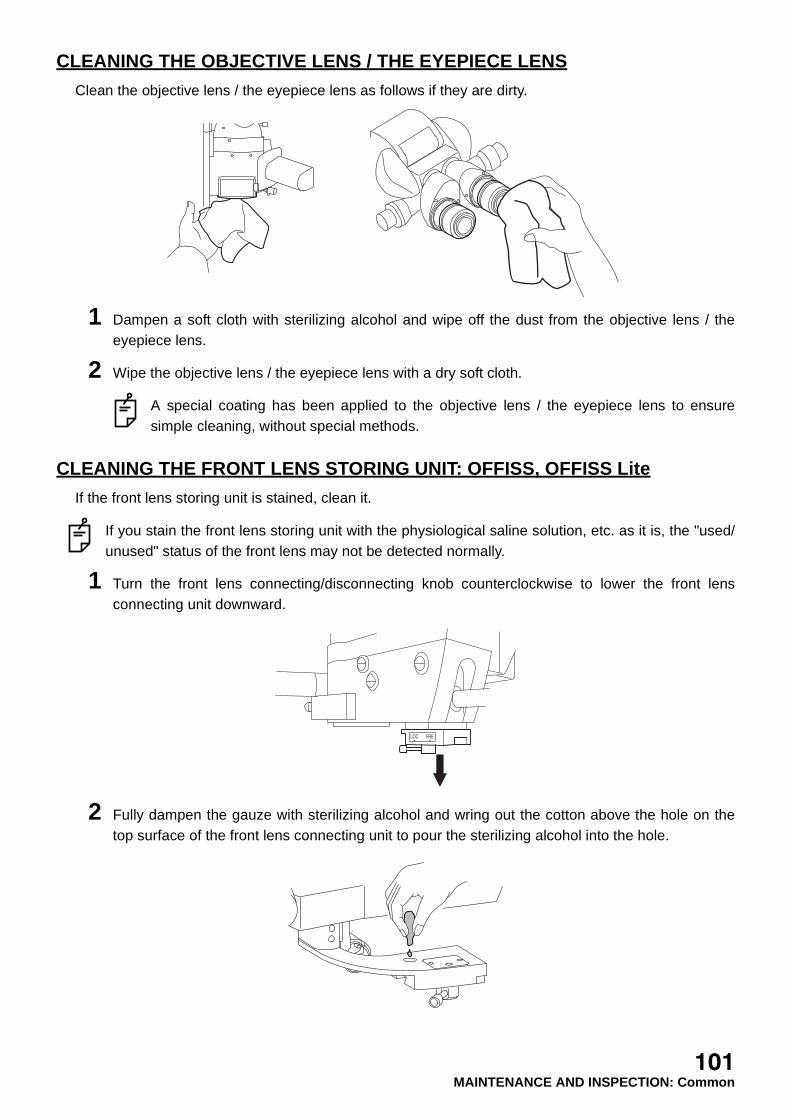
CLEANING THE OBJECTIVE LENS / THE EYEPIECE LENS
Clean the objective lens / the eyepiece lens as follows if they are dirty.
1 Dampen a soft cloth with sterilizing alcohol and wipe off the dust from the objective lens / theeyepiece lens.
2 Wipe the objective lens / the eyepiece lens with a dry soft cloth.
A special coating has been applied to the objective lens / the eyepiece lens to ensuresimple cleaning, without special methods.
CLEANING THE FRONT LENS STORING UNIT: OFFISS, OFFISS Lite
If the front lens storing unit is stained, clean it.
If you stain the front lens storing unit with the physiological saline solution, etc. as it is, the "used/unused" status of the front lens may not be detected normally.
1 Turn the front lens connecting/disconnecting knob counterclockwise to lower the front lensconnecting unit downward.
2 Fully dampen the gauze with sterilizing alcohol and wring out the cotton above the hole on thetop surface of the front lens connecting unit to pour the sterilizing alcohol into the hole.
LOC FRE
101MAINTENANCE AND INSPECTION: Common

3 Push the front of the shutter section (shadowed section as shown below) on the bottom of thefront lens storing unit with your finger and move the section forwards and backwards about fivetimes to remove the stain. Then, wipe the front lens storing unit with a dry cloth.
If you clean the front lens storing unit by pouring sterilizing alcohol as mentioned above, thecleaning will have a greater effect.
CLEANING THE REST APART FROM THE OPTICAL SYSTEM
ENSURING THE SAFETY WORK
CAUTION Do not use a strong cleaning agent, etc. This may damage theinstrument.
NOTE Wipe the instrument with a damp cloth.
NOTE To remove the sticky substances from the instrument, use a diluted neutralcleanser.
NOTE Do not use a strong cleaning agent, etc.
CAUTION Do not open the instrument, as this may lead to an electric shock.
NOTE Ask your distributor or the Topcon offices stated on the back cover to repair theinstrument.
102MAINTENANCE AND INSPECTION: Common
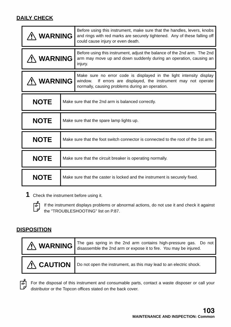
DAILY CHECK
1 Check the instrument before using it.
If the instrument displays problems or abnormal actions, do not use it and check it againstthe "TROUBLESHOOTING" list on P.87.
DISPOSITION
For the disposal of this instrument and consumable parts, contact a waste disposer or call yourdistributor or the Topcon offices stated on the back cover.
WARNINGBefore using this instrument, make sure that the handles, levers, knobsand rings with red marks are securely tightened. Any of these falling offcould cause injury or even death.
WARNINGBefore using this instrument, adjust the balance of the 2nd arm. The 2ndarm may move up and down suddenly during an operation, causing aninjury.
WARNINGMake sure no error code is displayed in the light intensity displaywindow. If errors are displayed, the instrument may not operatenormally, causing problems during an operation.
NOTE Make sure that the 2nd arm is balanced correctly.
NOTE Make sure that the spare lamp lights up.
NOTE Make sure that the foot switch connector is connected to the root of the 1st arm.
NOTE Make sure that the circuit breaker is operating normally.
NOTE Make sure that the caster is locked and the instrument is securely fixed.
WARNING The gas spring in the 2nd arm contains high-pressure gas. Do notdisassemble the 2nd arm or expose it to fire. You may be injured.
CAUTION Do not open the instrument, as this may lead to an electric shock.
103MAINTENANCE AND INSPECTION: Common
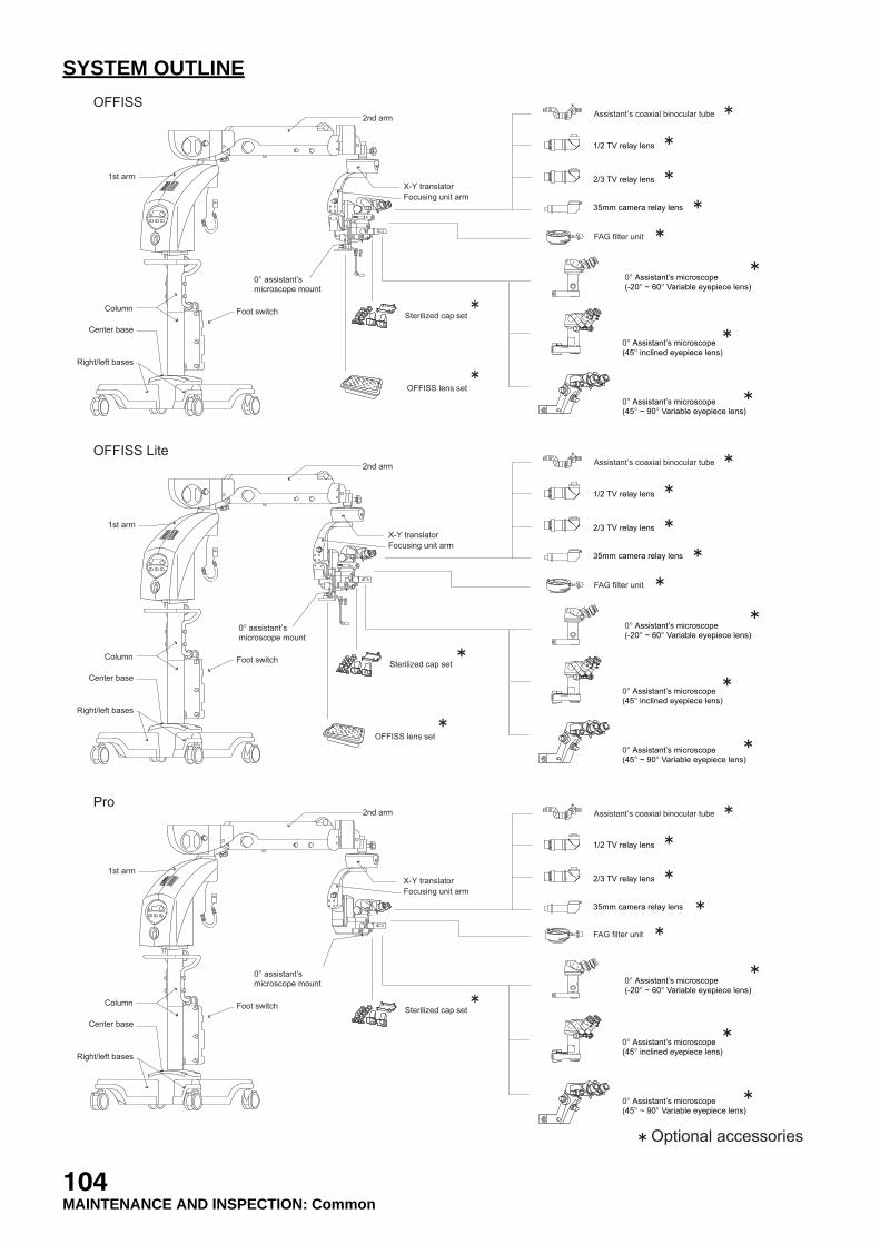
SYSTEM OUTLINE
1/2 TV relay lens
2/3 TV relay lens
35mm camera relay lens
0o Assistant�s microscope(-20o ~ 60o Variable eyepiece lens)
0o Assistant�s microscope(45o inclined eyepiece lens)
0o Assistant�s microscope(45o ~ 90o Variable eyepiece lens)
Pro
OFFISS
X-Y translator
OFFISS lens set
Sterilized cap set
Focusing unit arm
Foot switch
2nd arm
1st arm
Column
Center base
Right/left bases
0o assistant�smicroscope mount
X-Y translator
Sterilized cap set
Focusing unit arm
Foot switch
2nd arm
1st arm
Column
Center base
Right/left bases
0o assistant�smicroscope mount
Optional accessories
1/2 TV relay lens
2/3 TV relay lens
35mm camera relay lens
0o Assistant�s microscope(-20o ~ 60o Variable eyepiece lens)
0o Assistant�s microscope(45o inclined eyepiece lens)
0o Assistant�s microscope(45o ~ 90o Variable eyepiece lens)
Assistant�s coaxial binocular tube
FAG filter unit
1/2 TV relay lens
2/3 TV relay lens
35mm camera relay lens
0o Assistant�s microscope(-20o ~ 60o Variable eyepiece lens)
0o Assistant�s microscope(45o inclined eyepiece lens)
0o Assistant�s microscope(45o ~ 90o Variable eyepiece lens)
OFFISS Lite
X-Y translator
OFFISS lens set
Sterilized cap set
Focusing unit arm
Foot switch
2nd arm
1st arm
Column
Center base
Right/left bases
0o assistant�smicroscope mount
Assistant�s coaxial binocular tube
Assistant�s coaxial binocular tube
FAG filter unit
FAG filter unit
104MAINTENANCE AND INSPECTION: Common
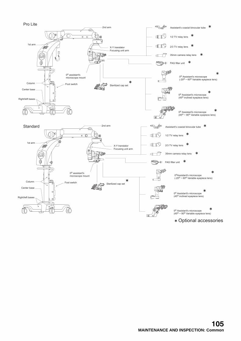
Standard
X-Y translator
Sterilized cap set
Focusing unit arm
Foot switch
2nd arm
1st arm
Column
Center base
Right/left bases
0o assistant'smicroscope mount
1/2 TV relay lens
2/3 TV relay lens
35mm camera relay lens
0oAssistant's microscope(-20o ~ 60o Variable eyepiece lens)
0o Assistant's microscope(45o inclined eyepiece lens)
0o Assistant's microscope(45o ~ 90o Variable eyepiece lens)
Pro Lite
X-Y translator
Sterilized cap set
Focusing unit arm
Foot switch
2nd arm
1st arm
Column
Center base
Right/left bases
0o assistant'smicroscope mount
Optional accessories
1/2 TV relay lens
2/3 TV relay lens
35mm camera relay lens
0o Assistant's microscope(-20o ~ 60o Variable eyepiece lens)
0o Assistant's microscope(45o inclined eyepiece lens)
0o Assistant's microscope(45o ~ 90o Variable eyepiece lens)
Assistant's coaxial binocular tube
FAG filter unit
FAG filter unit
Assistant's coaxial binocular tube
105MAINTENANCE AND INSPECTION: Common
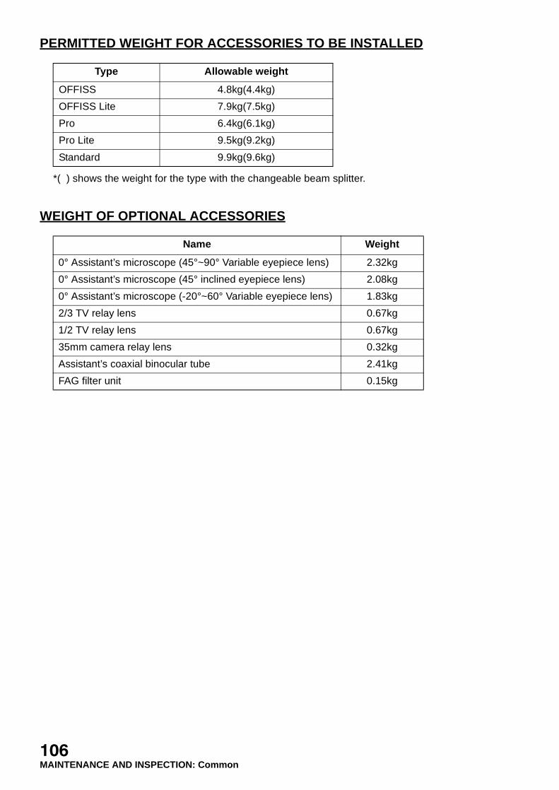
PERMITTED WEIGHT FOR ACCESSORIES TO BE INSTALLED
*( ) shows the weight for the type with the changeable beam splitter.
WEIGHT OF OPTIONAL ACCESSORIES
Type Allowable weight
OFFISS 4.8kg(4.4kg)
OFFISS Lite 7.9kg(7.5kg)
Pro 6.4kg(6.1kg)
Pro Lite 9.5kg(9.2kg)
Standard 9.9kg(9.6kg)
Name Weight
0° Assistant’s microscope (45°~90° Variable eyepiece lens) 2.32kg
0° Assistant’s microscope (45° inclined eyepiece lens) 2.08kg
0° Assistant’s microscope (-20°~60° Variable eyepiece lens) 1.83kg
2/3 TV relay lens 0.67kg
1/2 TV relay lens 0.67kg
35mm camera relay lens 0.32kg
Assistant’s coaxial binocular tube 2.41kg
FAG filter unit 0.15kg
106MAINTENANCE AND INSPECTION: Common

Please specify the following when contacting us re questions about thisoperation microscope.• Model name: OMS-800• Serial No.: Marked on the rating nameplate.• Period of use: Please inform us of the date of purchase.• Defective condition: Please provide us with as much detail as possible.
OPERATION MICROSCOPE OMS-800
INSTRUCTION MANUAL2004 version (2004.10-50TH )Date of issue: October 1, 2004
Published by TOPCON CORPORATION
75-1 Hasunuma-cho, Itabashi-ku, Tokyo, 174-8580 Japan.
©2004 TOPCON CORPORATION ALL RIGHTS RESERVED
2

OPERATION MICROSCOPE
OMS-800
45546 90052Printed in Japan 0410-50TH
75-1 Hasunuma-cho,Itabashi-ku,Tokyo,174-8580 Japan.
Phone:3-3558-2520 Fax:3-3960-4214 www.topcon.co.jp
37 West Century Road,Paramus,New Jersey 07652,U.S.A. Phone:201-261-9450 Fax:201-387-2710 www.topcon.comTOPCON MEDICAL SYSTEMS, INC
(European Representative)Essebaan 11, 2908 LJ Capelle a/d IJssel,THE NETHERLANDS Phone:010-4585077 Fax:010-4585045 www.topconeurope.com
TOPCON EUROPE B.V.
Giesserallee 31-33 D-47877 Willich GERMANY Phone:02154-8850 Fax:02154-885111 www.topcon.de [email protected] TOPCON DEUTSCHLAND G.m.b.H.
110 Provencher Avenue, Boisbriand, QC J7G 1N1 CANADA Phone:450-430-7771 Fax:450-430-6457 www.topcon.ca TOPCON CANADA INC.
HEAD OFFICE:Frederic Mompou 5, ED. Euro 3, 08960,Sant Just Desvern Barcelona,SPAIN Phone:93-4734057 Fax:93-4733932 www.topconesp.comMADRID OFFICE:Avenida Burgos, 16E,1˚ 28036,Madrid,SPAIN Phone:91-302-4129 Fax:91-383-3890
TOPCON ESPAÑA S.A.
Neongatan 2 S-43151 Mölndal, SWEDEN Phone:031-7109200 Fax:031-7109249 [email protected] SCANDINAVIA A.B.
Topcon House,Kennet Side,Bone Lane,Newbury,Berkshire RG14 5PX United Kingdom Phone:01635-551120 Fax:01635-551170TOPCON (GREAT BRITAIN) LTD.
Blk 192 Pandan Loop, #07-01 Pantech Industrial Complex, SINGAPORE 128381 Phone:62780222 Fax:62733540 www.topcon.com.sgTOPCON SOUTH ASIA PTE.LTD.
Excella Business Park Block C,1st Floor,Jalan Ampang Putra,Taman Ampang Hillir, 55100 Kuala Lumpur,MALAYSIA Phone:03-42701192 Fax:03-42704508TOPCON INSTRUMENTS (MALAYSIA) SDN.BHD.
77/162 Sinn Sathorn Tower, 37th Fl.,Krungdhonburi Rd.,Klongtonsai, Klongsarn, Bangkok 10600,THAILAND Phone:440-1152~7 Fax:440-1158TOPCON INSTRUMENTS (THAILAND) CO.,LTD.
Unit 18,4 Avenue of Americas Newington NSW 2127 AUSTRALIA Phone:02-8748-8777 Fax:02-9647-2926 www.topcon.com.au TOPCON AUSTRALIA PTY.LTD.
2F Yooseoung Bldg., 1595-3, Seocho-Dong, Seocho-Gu, Seoul, 137-876 KOREA Phone:02-2055-0321 Fax:02-2055-0319 www.topcon.co.krTOPCON KOREA CORPORATION
2/F.,Meeco Industrial Bldg.,No.53-55 Au Pui Wan Street,Fo Tan Road,Shatin,N.T.,Hong Kong Phone:2690-1328 Fax:2690-2221 E-mail:[email protected] OPTICAL (H.K.) LTD.
1070 Poly Plaza Building,14 Dongzhimen Nandajie Dongcheng District,Beijing,100027,CHINA Phone:10-6501-4191 Fax:10-6501-4190TOPCON CORPORATION BEIJING OFFICE
P.O.Box 70-1002 Antelias,BEIRUT-LEBANON Phone:961-4-523525/523526 Fax:961-4-521119TOPCON CORPORATION BEIRUT OFFICE
C/O Atlas Medical FZCO., P.O.Box 54304 C-25, Dubai Airport Free Zone, UAE Phone:971-4-2995900 Fax:971-4-2995901TOPCON CORPORATION DUBAI OFFICE
89, rue de Paris 92585 Clichy, Cedex,FRANCE Phone:01-4106-9494 Fax:01-4739-0251
ITALY OFFICE:Via Monfalcone 39, 20092 Cinisello B. mo (MI) ITALY Phone:02-61-25-583 Fax:02-61-25-927
TOPCON S.A.R.L.
2