Embed Size (px)
Citation preview
OMNIBUS HAI Omni-Bus Installation Software
User Guide
V1.0.4
Copyright © 2011 Home Automation, Inc. ALL RIGHTS RESERVED
®

OMNIBUS Software User Guide
Page 2 of 18
© 2011 Home Automation, Inc. ALL RIGHTS RESERVED
Rev 1.0.4
Table of Contents
1. INTRODUCTION ......................................................................................................................................... 3
2. REQUIREMENTS ........................................................................................................................................ 3
3. MODES OF OPERATION ........................................................................................................................... 3
3.1. ONLINE Mode .............................................................................................................................. 3
3.2. OFFLINE Mode ............................................................................................................................. 3
4. MAIN FORM FUNCTIONS .......................................................................................................................... 4
4.1. LIST DEVICES ............................................................................................................................. 4
4.2. LIST FROM PJT FILE ................................................................................................................... 4
4.3. SORT BUTTONS .......................................................................................................................... 5
4.4. MODE ........................................................................................................................................... 5
4.5. PORT ............................................................................................................................................ 5
4.6. BUS NETWORK NODES ............................................................................................................. 5
4.7. BUS LOGICAL DEVICES ............................................................................................................. 6
4.8. LIST FILTER ................................................................................................................................. 6
4.9. MORE BUTTON ........................................................................................................................... 6
4.10. LIST WINDOW ............................................................................................................................. 7
5. MAIN MENU FUNCTIONS .......................................................................................................................... 8
5.1. File ................................................................................................................................................ 8
5.2. Setup............................................................................................................................................. 8
5.3. Search........................................................................................................................................... 8
5.4. Device ........................................................................................................................................... 9
5.5. Tools ........................................................................................................................................... 10
6. COMMUNICATION PORT SETUP ........................................................................................................... 11
7. DEVICE SETUP ........................................................................................................................................ 12
7.1. DEVICE ALIAS ........................................................................................................................... 12
7.2. LOCAL PROGRAMMING ........................................................................................................... 13
7.3. NOTES........................................................................................................................................ 13
7.4. DEVICE SPECIFIC SETTINGS .................................................................................................. 13
8. DEVICE LINKS .......................................................................................................................................... 14
8.1. ADDING A LINK ......................................................................................................................... 14
8.1.1. ADD FROM NETWORK ............................................................................................................. 14
8.1.2. ADD RADIO REMOTE ............................................................................................................... 15
8.2. DELETING A LINK ..................................................................................................................... 15
9. MAINTAINING AN HAI OMNI-BUS NETWORK ....................................................................................... 16
9.1. BACKUP BUS NETWORK ......................................................................................................... 16
9.2. RESTORE BUS NETWORK ...................................................................................................... 16
9.3. RESTORING A DEVICE............................................................................................................. 16
9.4. REPLACING A FAULTY DEVICE .............................................................................................. 17
10. PREDEFINED REMOTE CONTROLS .................................................................................................. 18

OMNIBUS Software User Guide
Page 3 of 18
© 2011 Home Automation, Inc. ALL RIGHTS RESERVED
Rev 1.0.4
USB ProgrammingInterface
Omni-Bus NetworkCable
Splitter
PC Running OMNIBUSSoftware
1. INTRODUCTION The HAI Omni-Bus Installation Software (OMNIBUS) is used to configure and maintain all user programmable parameters of an HAI Omni-Bus Network Installation.
Typical Configuration
2. REQUIREMENTS
1. Computer running Windows XP®, Windows Vista® or Windows 7® operating system with OMNIBUS V1.0.2 software installed
2. Fully operational HAI Omni-Bus Network installation (see HAI Omni-Bus Network Installation Guide) 3. HAI Omni-Bus USB Programming Interface (116A00-1) or HAI Omni-Bus Interface Translator Rev 2
(117A00-1) 4. Available USB port on the computer or TCPIP network connection when used with a HAI Omni-Bus
Interface Translator Rev 2 in TCPIP Gateway mode.
3. MODES OF OPERATION
The OMNIBUS software has two modes of operation: OFFLINE and ONLINE, selectable by the MODE dropdown box on the main form.
3.1. ONLINE Mode This is used when the computer is connected to a ‘live’ HAI Omni-Bus Network via an Omni-Bus USB Programming Interface or Omni-Bus Interface Translator Rev 2. All changes are made directly to the Omni-Bus devices.
3.2. OFFLINE Mode The computer does not have to be connected to the Bus network. Changes are saved to a project file on the computer. This allows changes to be made offsite and restored to the devices at a later stage.

OMNIBUS Software User Guide
Page 4 of 18
© 2011 Home Automation, Inc. ALL RIGHTS RESERVED
Rev 1.0.4
4. MAIN FORM FUNCTIONS
4.1. LIST DEVICES
This item reads and lists all HAI Omni-Bus devices from a network (ONLINE mode) or project file (OFFLINE mode).
4.2. LIST FROM PJT FILE
When List from pjt file is checked in ONLINE mode, the list devices will be done from a project file instead of the bus network. All subsequent operations will however be performed directly on the bus network.

OMNIBUS Software User Guide
Page 5 of 18
© 2011 Home Automation, Inc. ALL RIGHTS RESERVED
Rev 1.0.4
4.3. SORT BUTTONS
This allows listed devices to be sorted by Serial number, Description, Alias, or Address.
4.4. MODE
This selects between Online and Offline mode.
4.5. PORT
This indicates the connection status of the communications port. For the USB Programming Interface or Interface Translator connected via USB a green check mark indicates that the interface is connected and ready. For an Interface Translator connected via TCPIP a green check mark indicates that a TCPIP connection has been established with the Interface Translator.
4.6. BUS NETWORK NODES
This is the number of Bus Network Nodes. A Bus Network Node is a physical bus device connected to a Bus network (e.g. a 4 Channel Relay Module will count as one Network Node).

OMNIBUS Software User Guide
Page 6 of 18
© 2011 Home Automation, Inc. ALL RIGHTS RESERVED
Rev 1.0.4
4.7. BUS LOGICAL DEVICES
This is the number of Bus Logical Devices. Bus Logical Devices are the devices listed in the device list. Each channel on a multi channel device is treated as a separate device (e.g. each 4 Channel Relay Module will count as four Logical Devices).
Note that this count will include all disabled channels on a DALI Gateway that are not shown in the device list.
4.8. LIST FILTER
This allows only certain device types or devices from a specific bus network to be listed.
4.9. MORE BUTTON
This changes the list columns to one of the following views:
STATUS, FIRMWARE REV
MODE
FREE/MAX LINKS, LOCAL PROG
NOTES
OMNIBUS Software User Guide
Page 7 of 18
© 2011 Home Automation, Inc. ALL RIGHTS RESERVED
Rev 1.0.4
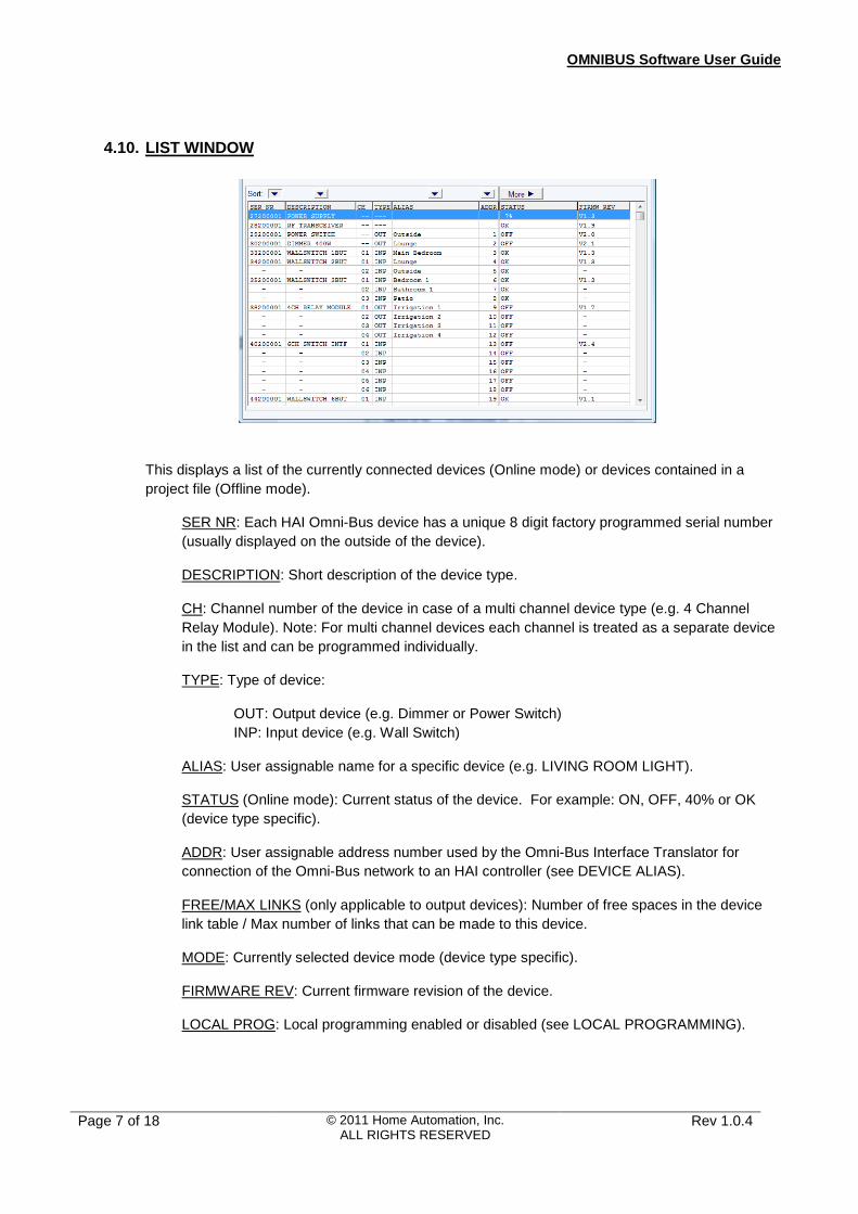
4.10. LIST WINDOW
This displays a list of the currently connected devices (Online mode) or devices contained in a project file (Offline mode).
SER NR: Each HAI Omni-Bus device has a unique 8 digit factory programmed serial number (usually displayed on the outside of the device).
DESCRIPTION: Short description of the device type.
CH: Channel number of the device in case of a multi channel device type (e.g. 4 Channel Relay Module). Note: For multi channel devices each channel is treated as a separate device in the list and can be programmed individually.
TYPE: Type of device:
OUT: Output device (e.g. Dimmer or Power Switch) INP: Input device (e.g. Wall Switch)
ALIAS: User assignable name for a specific device (e.g. LIVING ROOM LIGHT).
STATUS (Online mode): Current status of the device. For example: ON, OFF, 40% or OK (device type specific).
ADDR: User assignable address number used by the Omni-Bus Interface Translator for connection of the Omni-Bus network to an HAI controller (see DEVICE ALIAS).
FREE/MAX LINKS (only applicable to output devices): Number of free spaces in the device link table / Max number of links that can be made to this device.
MODE: Currently selected device mode (device type specific).
FIRMWARE REV: Current firmware revision of the device.
LOCAL PROG: Local programming enabled or disabled (see LOCAL PROGRAMMING).

OMNIBUS Software User Guide
Page 8 of 18
© 2011 Home Automation, Inc. ALL RIGHTS RESERVED
Rev 1.0.4
5. MAIN MENU FUNCTIONS
5.1. File New Project : Start a new project (offline mode)
Open Project : Open an existing project (offline mode)
Save Project : Save the existing project (offline mode)
Download Project to Bus : Download the current offline project to a Bus network (computer must be connected to the network)
Save Bus to Project File : Save the current Bus Network to a project file (online mode)
Restore Bus from Project File : Restore the current Bus Network from a previously saved project file (online mode)
5.2. Setup Program setup : Online/Offline selection
Communication Port Setup : Choose between USB Programming Interface, USB Interface Translator or TCPIP Interface Translator mode.
5.3. Search Find Alias: Search the current device list for a specific device Alias.

OMNIBUS Software User Guide
Page 9 of 18
© 2011 Home Automation, Inc. ALL RIGHTS RESERVED
Rev 1.0.4
5.4. Device This function is only available after selecting (clicking) a device in the device list. It contains various functions that can be performed on the currently selected device.
Note: Most functions can also be selected by right clicking on a device.
Setup : Open device Setup Form (see DEVICE SETUP)
Find Device (LED Flash) : Locate the physical device location of a device by flashing the LED on the device (online mode)
Find Device (OUTPUT Strobe) : Locate a device by switching the device output on and off (only applicable to output devices)
Set Program Mode : Set an output device in local program mode in order to manually link an input device to the output device (same as pressing and holding the button on the output device)
Restore From Project File : Restore only the settings and links for the selected device from a previously saved project file (online mode)
Swap Devices : Swap the alias, settings and links of two devices (offline mode)
Remove Device : Remove (delete) a device from the current project (offline mode)
Replace Device : Replace a device with a new device (offline mode). This in effect only changes the serial number of a device (see REPLACING A FAULTY DEVICE)

OMNIBUS Software User Guide
Page 10 of 18
© 2011 Home Automation, Inc. ALL RIGHTS RESERVED
Rev 1.0.4
5.5. Tools Identify Input Device : Identify an installed input device (e.g. A Wall Switch) by pressing the button on the device (online mode)
Test Device: Allows testing (ON, OFF, DIMMING, and LEVEL control) of the selected device or all bus devices (online mode).
Enable/Disable Local Programming: Enables or disables local programming for all connected or listed devices (see LOCAL PROGRAMMING)
Clear Links/Aliases/Addresses : Clear all the links, aliases, or addresses of the all currently connected or listed devices.
Auto Assign Addresses : Automatically assign addresses to all devices
Predefined Remote Controls : Allows RF Remote Controls to be added and managed (see PREDEFINED REMOTE CONTROLS)
DALIMAN : Runs Dali Configuration Software (for use with an Omni-Bus Dali Gateway)
TOOL LOCATIONS : Select the location of the DALIMAN software if different from default installed location

OMNIBUS Software User Guide
Page 11 of 18
© 2011 Home Automation, Inc. ALL RIGHTS RESERVED
Rev 1.0.4
6. COMMUNICATION PORT SETUP
On the Main Menu, select Setup, Communication Port Setup.
Under INTERFACE, select the appropriate option for the connected interface.
For a TCPIP connection, up to 10 different configurations can be saved.

OMNIBUS Software User Guide
Page 12 of 18
© 2011 Home Automation, Inc. ALL RIGHTS RESERVED
Rev 1.0.4
7. DEVICE SETUP
Double click on any device in the device list or select Device, Setup from the main menu to open the Device Setup form.
Select the Setup Tab on the form
7.1. DEVICE ALIAS
Note: With exception of the Device Address the alias is not used in any way by the devices themselves and is only for use by the system installer to easily identify and manage devices.
Type in the desired device alias into the Device Alias field or select a predefined alias from the dropdown list. The maximum alias length is 16 characters (14 if the Device Address enabled).
The second dropdown list allows a predefined suffix to be added to the alias (e.g. KITCHEN ‘LIGHT’). This list is fixed and cannot be edited. ‘Device no’ can be used to distinguish between different devices with the same alias.
If the device is to be used with an Omni-Bus Interface Translator for connection to an HAI Controller, enable the ‘Device Address” checkbox and assign a unique address to the device.
Click the SET button to save any changes to the device.

OMNIBUS Software User Guide
Page 13 of 18
© 2011 Home Automation, Inc. ALL RIGHTS RESERVED
Rev 1.0.4
7.2. LOCAL PROGRAMMING Local programming allows input devices to be linked to output devices without using the OMNIBUS software. Enable or disable this function here for this device.
7.3. NOTES Notes allow additional information about the device to be saved (only in offline mode)
7.4. DEVICE SPECIFIC SETTINGS
The bottom half of the Setup form (Setup TAB selected) contains settings specific to a certain device type such as minimum and maximum light levels for a dimmer or button mode for a wall switch. See the device documentation for more info on the various options.
SET: Click this button to update a device with the selected settings.
SET DEFAULTS : Restore a device to its factory default settings.
APPLY TO ALL DEVICES OFF THIS TYPE : Check to apply the settings to all similar devices.
APPLY TO ALL CHANNELS ON THIS DEVICE : Check to apply the settings to all channels of the selected device in case of a multi channel device.

OMNIBUS Software User Guide
Page 14 of 18
© 2011 Home Automation, Inc. ALL RIGHTS RESERVED
Rev 1.0.4
8. DEVICE LINKS Device Links are used to link input and output devices to each other (e.g. having a certain wall switch button control a specific dimmer device).
All device links are stored in the Output Device (Dimmer, Power Switch, Relay Module, etc.).
Double click on any device in the device list or select Device, Setup from the main menu to open the Device Setup form.
Select the Links Tab on the setup form
The list will show the currently linked devices for the selected device. Double click on a link to jump to the linked device.
8.1. ADDING A LINK Two options are available when adding a link to a device:
8.1.1. ADD FROM NETWORK
This is used to add a Bus device. A list of available bus devices that can be linked to the selected device will be displayed. If the selected device is an output device, only input devices will be shown and vice versa. Click on the device to be linked and click the add button.

OMNIBUS Software User Guide
Page 15 of 18
© 2011 Home Automation, Inc. ALL RIGHTS RESERVED
Rev 1.0.4
8.1.2. ADD RADIO REMOTE Use to add a RF Remote control (only applicable to output devices).
Three options are available here:
1. Add by using Predefined Remote Controls
See PREDEFINED REMOTE CONTROLS
2. Add by Capturing a remote control (online mode only)
If a Bus RF Transceiver is connected to the network, the remote control can be captured via the Bus RF Transceiver and linked to the device. Note: Set the Bus RF Transceiver in the ‘Open Mode’ (Receive All RF Remote Controls).
3. Add by Entering the remote control serial number
If the remote control serial number is known, this option can be used to enter the serial number and selecting the desired channel to be linked to the output device.
8.2. DELETING A LINK
Select the link to be deleted from the link list and click DELETE to remove this link or click DELETE ALL to remove all links for this device.

OMNIBUS Software User Guide
Page 16 of 18
© 2011 Home Automation, Inc. ALL RIGHTS RESERVED
Rev 1.0.4
9. MAINTAINING A HAI OMNI-BUS NETWORK
9.1. BACKUP BUS NETWORK This function allows for all settings and links in a completed installation to be saved to a project file.
In Online Mode: select File, Save Bus to Project File from the main menu.
9.2. RESTORE BUS NETWORK This function allows a Bus network to be restored from a saved or changed project file.
In Online Mode: select File, Restore Bus from Project File from the main menu.
or
In Offline Mode: select File, Download Project to Bus from the main menu.
In each case, three checkboxes will be presented allowing only Aliases, Links, or Settings to be restored.
9.3. RESTORING A DEVICE Use to restore only a single device from a saved or changed project file.
Select the device from the device list then select Device, Restore from Project File from the main menu (see also REPLACING A FAULTY DEVICE).

OMNIBUS Software User Guide
Page 17 of 18
© 2011 Home Automation, Inc. ALL RIGHTS RESERVED
Rev 1.0.4
9.4. REPLACING A FAULTY DEVICE First save the current bus network to a project file (see BACKUP BUS NETWORK) or use a previously saved project.
Open the project in the OFFLINE mode and click LIST DEVICES.
Select the device to be replaced from the listed devices (note: for a multi channel device, channel number 1 must be selected).
From the main menu select Device, Replace Device .
Select a new device from the dropdown list and enter the serial number of the new device. Click REPLACE .
Save the project file.
Install the new device into the Bus Network.
Return to the ONLINE mode and click LIST DEVICES. Select the newly installed device and select Device, Restore from Project File from the main menu.

OMNIBUS Software User Guide
Page 18 of 18
© 2011 Home Automation, Inc. ALL RIGHTS RESERVED
Rev 1.0.4
10. PREDEFINED REMOTE CONTROLS
Predefined Remote Controls allows for Omni-Bus RF Remote controls to be defined, managed, and saved for later use.
All currently loaded remote info is automatically saved as part of the project file.
Remote control info can also be saved as a separate file (.RCF file) for use in different projects.
From the main menu, select Tools, Predefined Remote Controls:
NEW: Clears existing info and start with a new list
LOAD: Load info from a Remote Control file (.RCF) or import info from a Project file (.PJT)
EDIT: Change the properties of one of the selected remote controls from the list
ADD: Add a new remote
DELETE: Delete the selected remote from the list
SAVE: Save the remote info to a Remote Control file (.RCF) file
TEST: Emulate the remote control by sending the RF packet to all bus devices. An option is also available to transmit the packet via the selected Bus RF Transceiver.