Embed Size (px)
Citation preview
OMG Systems Modeling Language (OMG SysML™), V1.1OMG Available Specification(RTF Convenience Document update, with change bars)
OMG Document Number: ptc/2008-05-16Standard document URL: http://www.omg.org/spec/SysML/1.1/PDFAssociated Schema Files: (RTF XMI zip file update: ptc/2008-05-18)
http://www.omg.org/spec/SysML/2008xxxx/SysML-profile.xmihttp://www.omg.org/spec/SysML/2008xxxx/Activities-model.xmihttp://www.omg.org/spec/SysML/2008xxxx/Blocks-model.xmihttp://www.omg.org/spec/SysML/2008xxxx/UML4SysML-metamodel.xmi
Version 1.1 is a minor revision of the OMG SysML 1.0 specification. It supersedes formal/2007-09-01.
Refer to the Roadmap located in the Preface for a list of documents that were generated as part of the adoption, finalization, and revision process.
Copyright © 2003-2006, American Systems CorporationCopyright © 2003-2006, ARTiSAN Software ToolsCopyright © 2003-2006, BAE SYSTEMSCopyright © 2003-2006, The Boeing CompanyCopyright © 2003-2006, Ceira TechnologiesCopyright © 2003-2006, Deere & CompanyCopyright © 2003-2006, EADS Astrium GmbHCopyright © 2003-2006, EmbeddedPlus EngineeringCopyright © 2003-2006, Eurostep Group ABCopyright © 2003-2006, Gentleware AGCopyright © 2003-2006, I-Logix, Inc.Copyright © 2003-2006, International Business MachinesCopyright © 2003-2006, International Council on Systems EngineeringCopyright © 2003-2006, Israel Aircraft IndustriesCopyright © 2003-2006, Lockheed Martin CorporationCopyright © 2003-2006, Mentor GraphicsCopyright © 2003-2006, Motorola, Inc.National Institute of Standards and TechnologyCopyright © 2003-2006, Northrop GrummanCopyright © 1997-2007, Object Management GroupCopyright © 2003-2006, oose Innovative Informatik GmbHCopyright © 2003-2006, PivotPoint Technology CorporationCopyright © 2003-2006, Raytheon CompanyCopyright © 2003-2006, Sparx SystemsCopyright © 2003-2006, Telelogic ABCopyright © 2003-2006, THALES
USE OF SPECIFICATION - TERMS, CONDITIONS & NOTICES
The material in this document details an Object Management Group specification in accordance with the terms, conditions and notices set forth below. This document does not represent a commitment to implement any portion of this specification in any company's products. The information contained in this document is subject to change without notice.
The specification customizes the Unified Modeling Language (UML) specification of the Object Management Group (OMG) to address the requirements of Systems Engineering as specified in the UML for Systems Engineering RFP, OMG document number ad/2003-03-41. This document includes references to and excerpts from the UML 2.0 Superstructure Specification and UML 2.0 Infrastructure Specification with copyright holders and conditions as noted in those documents.
LICENSES
Redistribution and use of this specification, with or without modification, are permitted provided that the following conditions are met: (1) Redistributions of this specification must reproduce the above copyright notice, this list of conditions and disclaimers in the documentation and/or other materials provided with the distribution; (2) The Copyright Holders listed in the above copyright notice may not be used to endorse or promote products derived from this specification without specific prior written permission; (3) All modified versions of this specification must include a prominent notice stating how and when the specification was modified; and (4) No modifications to this OMG SysML™
specification may be published under or identified by that name, except for versions published by OMG and incorporating official changes made through the applicable procedures of OMG. OMG SysML™ is a trademark of OMG, and no unauthorized version or revision of the OMG SysML specification may use the trademark “OMG SysML” or claim any connection with or endorsement by OMG.
In accordance with the above copyright provisions, the companies listed above have granted to the Object Management Group, Inc. (OMG) a nonexclusive, royalty-free, paid up, worldwide license to copy and distribute OMG SysML and to modify OMG SysML and distribute copies of the modified version. Each of the copyright holders listed above has agreed that no person shall be deemed to have infringed the copyright in the included material of any such copyright holder by reason of having used the specification set forth herein or having conformed any computer software to the specification. Subject to all of the terms and conditions below, the owners of the copyright in this specification hereby grant you a fully-paid up, non-exclusive, nontransferable, nonsublicenseable, perpetual, worldwide license, to use this specification to create and distribute software and special purpose specifications that are based upon this specification, and to use, copy, and distribute this specification as provided under the Copyright Act. This limited permission automatically terminates without notice if you breach any of these terms or conditions. Upon termination, you will destroy immediately any copies of this document in your possession or control.
This document was derived from the "Systems Modeling Language (SysML) Specification, version 1.0 DRAFT", OMG document (ad/2006-03-01) submitted to OMG in response to the "UML for Systems Engineering RFP" (ad/2003-03-41). Review and editing in the OMG process produced the "OMG SysML Specification Final Adopted Specification" (ptc/2006-05-04). Subsequent changes to the specification are controlled through the OMG process as documented at the OMG Technology Document website - http://www.omg.org/technology/documents/.
PATENTS
The attention of adopters is directed to the possibility that compliance with or adoption of OMG specifications may require use of an invention covered by patent rights. OMG shall not be responsible for identifying patents for which a license may be required by any OMG specification, or for conducting legal inquiries into the legal validity or scope of those patents that are brought to its attention. OMG specifications are prospective and advisory only. Prospective users are responsible for protecting themselves against liability for infringement of patents.
GENERAL USE RESTRICTIONS
Any unauthorized use of this specification may violate copyright laws, trademark laws, and communications regulations and statutes. This document contains information which is protected by copyright. All Rights Reserved. No part of this work covered by copyright herein may be reproduced or used in any form or by any means--graphic, electronic, or mechanical, including photocopying, recording, taping, or information storage and retrieval systems--without permission of the copyright owner.
DISCLAIMER OF WARRANTY
WHILE THIS PUBLICATION IS BELIEVED TO BE ACCURATE, IT IS PROVIDED “AS IS” AND MAY CONTAIN ERRORS OR MISPRINTS. THE OBJECT MANAGEMENT GROUP AND THE COMPANIES LISTED ABOVE MAKE NO WARRANTY OF ANY KIND, EXPRESS OR IMPLIED, WITH REGARD TO THIS PUBLICATION, INCLUDING BUT NOT LIMITED TO ANY WARRANTY OF TITLE OR OWNERSHIP, IMPLIED WARRANTY OF MERCHANTABILITY OR WARRANTY OF FITNESS FOR A PARTICULAR PURPOSE OR USE. IN NO EVENT SHALL THE OBJECT MANAGEMENT GROUP OR ANY OF THE COMPANIES LISTED ABOVE BE LIABLE FOR ERRORS CONTAINED HEREIN OR FOR DIRECT, INDIRECT, INCIDENTAL, SPECIAL, CONSEQUENTIAL, RELIANCE OR COVER DAMAGES, INCLUDING LOSS OF PROFITS, REVENUE, DATA OR USE, INCURRED
BY ANY USER OR ANY THIRD PARTY IN CONNECTION WITH THE FURNISHING, PERFORMANCE, OR USE OF THIS MATERIAL, EVEN IF ADVISED OF THE POSSIBILITY OF SUCH DAMAGES. The entire risk as to the quality and performance of software developed using this specification is borne by you. This disclaimer of warranty constitutes an essential part of the license granted to you to use this specification.
RESTRICTED RIGHTS LEGEND
Use, duplication or disclosure by the U.S. Government is subject to the restrictions set forth in subparagraph (c) (1) (ii) of The Rights in Technical Data and Computer Software Clause at DFARS 252.227-7013 or in subparagraph (c)(1) and (2) of the Commercial Computer Software - Restricted Rights clauses at 48 C.F.R. 52.227-19 or as specified in 48 C.F.R. 227-7202-2 of the DoD F.A.R. Supplement and its successors, or as specified in 48 C.F.R. 12.212 of the Federal Acquisition Regulations and its successors, as applicable. The specification copyright owners are as indicated above and may be contacted through the Object Management Group, 140 Kendrick Street, Needham, MA 02494, U.S.A.
TRADEMARKS
OMG SysML™ is a trademark of the Object Management Group. The OMG Object Management Group Logo®, CORBA®, CORBA Academy®, The Information Brokerage®, XMI® and IIOP® are registered trademarks of the Object Management Group. OMG™, Object Management Group™, CORBA logos™, OMG Interface Definition Language (IDL)™, The Architecture of Choice for a Changing World™, CORBAservices™, CORBAfacilities™, CORBAmed™, CORBAnet™, Integrate 2002™, Middleware That's Everywhere™, UML™, Unified Modeling Language™, The UML Cube logo™, MOF™, CWM™, The CWM Logo™, Model Driven Architecture™, Model Driven Architecture Logos™, MDA™, OMG Model Driven Architecture™, OMG MDA™ and the XMI Logo™ are trademarks of the Object Management Group. All other products or company names mentioned are used for identification purposes only, and may be trademarks of their respective owners.
COMPLIANCE
The Object Management Group (acting itself or through its designees) is and shall at all times be the sole entity that may authorize developers, suppliers and sellers of computer software to use certification marks, trademarks or other special designations to indicate compliance with OMG SysML™. Software developed under the terms of this license may claim compliance or conformance with this specification if and only if the software compliance is of a nature fully matching the applicable compliance points as stated in the specification. Software developed only partially matching the applicable compliance points may claim only that the software was based on this specification, but may not claim compliance or conformance with this specification. In the event that testing suites are implemented or approved by Object Management Group, Inc., software developed using this specification may claim compliance or conformance with the specification only if the software satisfactorily completes the testing suites.


OMG’s Issue Reporting Procedure
All OMG specifications are subject to continuous review and improvement. As part of this process we encourage readers to report any ambiguities, inconsistencies, or inaccuracies they may find by completing the Issue Reporting Form listed on the main web page http://www.omg.org, under Documents, Report a Bug/Issue (http://www.omg.org/technology/agreement.htm).

Table of Contents
Part I - Introduction ............................................................................................... 1
1 Scope ............................................................................................................... 3
2 Normative References ..................................................................................... 3
3 Additional Information ...................................................................................... 43.1 Relationships to Other Standards ................................................................................... 43.2 How to Read this Specification ....................................................................................... 43.3 Acknowledgments ........................................................................................................... 4
4 Language Architecture ..................................................................................... 74.1 Design Principles ............................................................................................................ 74.2 Architecture ..................................................................................................................... 84.3 Extension Mechanisms ................................................................................................. 104.4 SysML Diagrams ........................................................................................................... 11
5 Compliance .................................................................................................... 135.1 Compliance with UML Subset (UML4SysML) ............................................................... 13
5.1.1 Compliance Level Contents .......................................................................................... 13
5.2 Compliance with SysML Extensions ............................................................................. 145.3 Meaning of Compliance ................................................................................................ 15
6 Language Formalism ..................................................................................... 176.1 Levels of Formalism ...................................................................................................... 176.2 Chapter Specification Structure .................................................................................... 17
6.2.1 Overview ....................................................................................................................... 176.2.2 Diagram Elements ........................................................................................................ 176.2.3 UML Extensions ........................................................................................................... 18
6.2.3.1 Usage Examples ................................................................................................................18
6.3 Conventions and Typography ....................................................................................... 18
Part II - Structural Constructs ............................................................................. 19
7 Model Elements ............................................................................................. 217.1 Overview ....................................................................................................................... 217.2 Diagram Elements ........................................................................................................ 21
OMG SysMLTM , Version 1.0 i
7.3 UML Extensions ............................................................................................................ 257.3.1 Diagram Extensions ..................................................................................................... 25
7.3.1.1 Stereotype Keywords or Icons Inside a Comment Note Box ..............................................25 7.3.1.2 UML Diagram Elements not Included in SysML .................................................................25
7.3.2 Stereotypes .................................................................................................................. 26 7.3.2.1 Conform ..............................................................................................................................26 7.3.2.2 Problem ..............................................................................................................................26 7.3.2.3 Rationale ............................................................................................................................26 7.3.2.4 View ....................................................................................................................................27 7.3.2.5 Viewpoint ............................................................................................................................27
7.4 Usage Examples ........................................................................................................... 28
8 Blocks ............................................................................................................ 318.1 Overview ....................................................................................................................... 318.2 Diagram Elements ......................................................................................................... 32
8.2.1 Block Definition Diagram .............................................................................................. 328.2.2 Internal Block Diagram ................................................................................................. 37
8.3 UML Extensions ............................................................................................................ 388.3.1 Diagram Extensions ..................................................................................................... 38
8.3.1.1 Block Definition Diagram ....................................................................................................38 8.3.1.2 Internal Block Diagram .......................................................................................................40 8.3.1.3 UML Diagram Elements not Included in SysML Block Definition Diagrams .......................42 8.3.1.4 UML Diagram Elements not Included in SysML Internal Block Diagrams ..........................42
8.3.2 Stereotypes .................................................................................................................. 42 8.3.2.1 Binding Connector ..............................................................................................................44 8.3.2.2 Block ...................................................................................................................................44 8.3.2.3 ConnectorProperty .............................................................................................................46 8.3.2.4 DistributedProperty .............................................................................................................46 8.3.2.5 Dimension ...........................................................................................................................47 8.3.2.6 NestedConnectorEnd .........................................................................................................47 8.3.2.7 ParticipantProperty .............................................................................................................47 8.3.2.8 PropertySpecificType .........................................................................................................48 8.3.2.9 Unit .....................................................................................................................................48 8.3.2.10 ValueType ........................................................................................................................ 49
8.3.3 Model Libraries ............................................................................................................. 49 8.3.3.1 Complex .............................................................................................................................50 8.3.3.2 Real ....................................................................................................................................50
8.4 Usage Examples ........................................................................................................... 508.4.1 Wheel Hub Assembly ................................................................................................... 508.4.2 SI Value Types ............................................................................................................. 528.4.3 Design Configuration for SUV EPA Fuel Economy Test .............................................. 538.4.4 Water Delivery .............................................................................................................. 55
9 Ports and Flows ............................................................................................. 599.1 Overview ....................................................................................................................... 59
9.1.1 Standard Ports .............................................................................................................. 599.1.2 Flow Ports ..................................................................................................................... 599.1.3 Item Flows .................................................................................................................... 59
ii OMG SysMLTM , Version 1.0
9.2 Diagram Elements ........................................................................................................ 609.2.1 Extensions to Block Definition Diagram ........................................................................ 60
9.2.1.1 Extensions to Internal Block Diagram................................................................................. 62
9.3 UML Extensions ............................................................................................................ 639.3.1 Diagram Extensions ..................................................................................................... 63
9.3.1.1 FlowPort .............................................................................................................................63 9.3.1.2 FlowProperty ...................................................................................................................... 63 9.3.1.3 FlowSpecification ................................................................................................................ 64 9.3.1.4 ItemFlow .............................................................................................................................64
9.3.2 Stereotypes .................................................................................................................. 64 9.3.2.1 Block................................................................................................................................... 65 9.3.2.2 FlowDirection ...................................................................................................................... 65 9.3.2.3 FlowPort .............................................................................................................................65 9.3.2.4 FlowProperty ...................................................................................................................... 67 9.3.2.5 FlowSpecification................................................................................................................ 68 9.3.2.6 ItemFlow.............................................................................................................................. 68 9.3.2.7 Standard Port ..................................................................................................................... 69
9.4 Usage Examples............................................................................................................ 699.4.1 Standard Ports .............................................................................................................. 69
9.4.1.1 Atomic Flow Ports and Item Flows .....................................................................................71 9.4.1.2 Non-Atomic Flow Ports and Flow Specification ..................................................................72
10 Constraint Blocks ......................................................................................... 7510.1 Overview ..................................................................................................................... 7510.2 Diagram Elements ...................................................................................................... 76
10.2.1 Block Definition Diagram ............................................................................................ 7610.2.2 Parametric Diagram .................................................................................................... 77
10.3 UML Extensions .......................................................................................................... 7710.3.1 Diagram Extensions ................................................................................................... 77
10.3.1.1 Block Definition Diagram ................................................................................... 77 10.3.1.2 Parametric Diagram ........................................................................................... 78
10.3.2 Stereotypes ................................................................................................................ 78 10.3.2.1 ConstraintBlock ................................................................................................................ 79 10.3.2.2 ConstraintProperty ............................................................................................................79
10.4 Usage Examples ......................................................................................................... 7910.4.1 Definition of Constraint Blocks on a Block Definition Diagram ................................... 7910.4.2 Usage of Constraint Blocks on a Parametric Diagram ................................................ 80
Part III - Behavioral Constructs ........................................................................... 83
11 Activities ........................................................................................................ 8511.1 Overview ..................................................................................................................... 85
11.1.1 Control as Data ........................................................................................................... 8511.1.2 Continuous Systems ................................................................................................... 8511.1.3 Probability ................................................................................................................... 8511.1.4 Activities as Classes ................................................................................................... 8611.1.5 Timelines .................................................................................................................... 86
OMG SysMLTM , Version 1.0 iii
11.2 Diagram Elements ....................................................................................................... 8611.2.1 Activity Diagram .......................................................................................................... 86
11.3 UML Extensions .......................................................................................................... 9311.3.1 Diagram Extensions ................................................................................................... 93
11.3.1.1 Activity ..............................................................................................................................94 11.3.1.2 CallBehaviorAction ...........................................................................................................95 11.3.1.3 ControlFlow ......................................................................................................................95 11.3.1.4 ObjectNode .......................................................................................................................96
11.3.2 Stereotypes ................................................................................................................ 97 11.3.2.1 Continuous ....................................................................................................................... 98 11.3.2.2 ControlOperator ................................................................................................................99 11.3.2.3 Discrete ............................................................................................................................ 99 11.3.2.4 NoBuffer ...........................................................................................................................99 11.3.2.5 Overwrite ........................................................................................................................100 11.3.2.6 Optional ..........................................................................................................................100 11.3.2.7 Probability .......................................................................................................................100 11.3.2.8 Rate ................................................................................................................................101
11.3.3 Model Libraries ......................................................................................................... 101 11.3.3.1 ControlValue ...................................................................................................................101
11.4 Usage Examples ....................................................................................................... 102
12 Interactions ................................................................................................. 10712.1 Overview ................................................................................................................... 10712.2 Diagram Elements ..................................................................................................... 107
12.2.1 Sequence Diagram ................................................................................................... 107
12.3 UML Extensions ........................................................................................................ 11112.3.1 Diagram Extensions ................................................................................................. 111
12.3.1.1 Exclusion of Communication Diagram, Interaction Overview Diagram, and Timing Diagram .............................................................................................................111
12.4 Usage Examples ....................................................................................................... 11212.4.1 Sequence Diagrams ................................................................................................. 112
13 State Machines ........................................................................................... 11513.1 Overview ................................................................................................................... 11513.2 Diagram Elements ..................................................................................................... 115
13.2.1 State Machine Diagram ............................................................................................ 115
13.3 UML Extensions ........................................................................................................ 11813.4 Usage Examples ....................................................................................................... 118
13.4.1 State Machine Diagram ............................................................................................ 118
14 Use Cases .................................................................................................. 12114.1 Overview ................................................................................................................... 12114.2 Diagram Elements ..................................................................................................... 121
14.2.1 Use Case Diagram ................................................................................................... 121
iv OMG SysMLTM , Version 1.0
14.3 UML Extensions ........................................................................................................ 12314.4 Usage Examples ....................................................................................................... 124
Part IV - Crosscutting Constructs ..................................................................... 127
15 Allocations ................................................................................................... 12915.1 Overview ................................................................................................................... 12915.2 Diagram Elements .................................................................................................... 129
15.2.1 Representing Allocation on Diagrams ...................................................................... 130
15.3 UML Extensions ....................................................................................................... 13115.3.1 Diagram Extensions ................................................................................................. 131
15.3.1.1 Tables .............................................................................................................................131 15.3.1.2 Allocate Relationship Rendering ....................................................................................131 15.3.1.3 Allocated Property Compartment Format ....................................................................... 131 15.3.1.4 Allocated Property Callout Format .................................................................................. 131 15.3.1.5 AllocatedActivityPartition Label ......................................................................................132
15.3.2 Stereotypes .............................................................................................................. 132 15.3.2.1 Allocate(from Allocations) ...............................................................................................132 15.3.2.2 Allocated(from Allocations) ............................................................................................. 133 15.3.2.3 AllocateActivityPartition(from Allocations) ......................................................................134
15.4 Usage Examples ....................................................................................................... 13415.4.1 Behavior Allocation of Actions to Parts and Activities to Blocks ............................... 13515.4.2 Allocate Flow ............................................................................................................ 136
15.4.2.1 Allocating Structure .......................................................................................................137 15.4.2.2 Automotive Example ...................................................................................................... 138
15.4.3 Tabular Representation ............................................................................................ 139
16 Requirements .............................................................................................. 14116.1 Overview ................................................................................................................... 14116.2 Diagram Elements .................................................................................................... 143
16.2.1 Requirement Diagram .............................................................................................. 143
16.3 UML Extensions ........................................................................................................ 14616.3.1 Diagram Extensions ................................................................................................. 146
16.3.1.1 Requirement Diagram ....................................................................................................146 16.3.1.2 Requirement Notation .....................................................................................................146 16.3.1.3 Requirement Property Callout Format ............................................................................146 16.3.1.4 Requirements on Other Diagrams .................................................................................. 146 16.3.1.5 Requirements Table .......................................................................................................147
16.3.2 Stereotypes .............................................................................................................. 148 16.3.2.1 Copy ............................................................................................................................... 149 16.3.2.2 DeriveReqt ......................................................................................................................149 16.3.2.3 Requirement ...................................................................................................................150 16.3.2.4 RequirementRelated .......................................................................................................151 16.3.2.5 TestCase ........................................................................................................................151 16.3.2.6 Satisfy .............................................................................................................................151 16.3.2.7 Verify ..............................................................................................................................152
16.4 Usage Examples ....................................................................................................... 152
OMG SysMLTM , Version 1.0 v
16.4.1 Requirement Decomposition and Traceability .......................................................... 152 16.4.1.1 Requirements and Design Elements ..............................................................................152 16.4.1.2 Requirements Reuse ......................................................................................................154 16.4.1.3 Verification Procedure (Test Case) ................................................................................155
17 Profiles & Model Libraries ........................................................................... 15717.1 Overview ................................................................................................................... 15717.2 Diagram Elements ..................................................................................................... 158
17.2.1 Profile Definition in Class Diagram ........................................................................... 158 17.2.1.1 Extension ........................................................................................................................160
17.2.2 Stereotypes Used On Diagrams ............................................................................... 161 17.2.2.1 StereotypeInNode ...........................................................................................................162 17.2.2.2 StereotypeInComment ....................................................................................................162 17.2.2.3 StereotypeInCompartment .............................................................................................163
17.3 UML Extensions ........................................................................................................ 16317.4 Usage Examples ....................................................................................................... 163
17.4.1 Defining a Profile ...................................................................................................... 16317.4.2 Adding Stereotypes to a Profile ................................................................................ 16417.4.3 Defining a Model Library that Uses a Profile ............................................................ 16517.4.4 Guidance on Whether to Use a Stereotype or Class ................................................. 16517.4.5 Using a Profile .......................................................................................................... 16617.4.6 Using a Stereotype ................................................................................................... 16717.4.7 Using a Model Library Element ................................................................................ 167
Part V - Annexes .............................................................................................. 169
Annex A: Diagrams .................................................................................................... 171
Annex B - Sample Problem ........................................................................................ 177
Annex C - Non-normative Extensions ........................................................................ 211
Annex D - Model Interchange ..................................................................................... 223
Annex E - Requirements Traceability ......................................................................... 229
Annex F - Terms and Definitions ................................................................................ 231
vi OMG SysMLTM , Version 1.0
List of Figures
Figure 1.1- Overview of SysML/UML interrelationship . . . . . . . . . . . . . . . . . . . . . . . . . . . . . . . . . . . . . . 7
Figure 4.1- SysML Extension of UML . . . . . . . . . . . . . . . . . . . . . . . . . . . . . . . . . . . . . . . . . . . . . . . . . . . 8Figure 4.2- SysML Package Structure . . . . . . . . . . . . . . . . . . . . . . . . . . . . . . . . . . . . . . . . . . . . . . . . . . . 10Figure 4.3- SysML Diagram Taxonomy . . . . . . . . . . . . . . . . . . . . . . . . . . . . . . . . . . . . . . . . . . . . . . . . . 11
Figure 7.1- Notation for the Rationale Stereotype of Comment . . . . . . . . . . . . . . . . . . . . . . . . . . . . . . . 25Figure 7.2- Stereotypes defined in package ModelElements . . . . . . . . . . . . . . . . . . . . . . . . . . . . . . . . . . 26Figure 7.3- View/Viewpoint example . . . . . . . . . . . . . . . . . . . . . . . . . . . . . . . . . . . . . . . . . . . . . . . . . . . 28Figure 7.4- Rationale and Problem examples . . . . . . . . . . . . . . . . . . . . . . . . . . . . . . . . . . . . . . . . . . . . . 29
Figure 8.1- Nested property reference . . . . . . . . . . . . . . . . . . . . . . . . . . . . . . . . . . . . . . . . . . . . . . . . . . . 41Figure 8.2- Abstract syntax expressions for SysML blocks . . . . . . . . . . . . . . . . . . . . . . . . . . . . . . . . . . 42Figure 8.3- Abstract syntax extensions for SysML properties . . . . . . . . . . . . . . . . . . . . . . . . . . . . . . . . . 43Figure 8.4- Abstract syntax extensions for SysML value types . . . . . . . . . . . . . . . . . . . . . . . . . . . . . . . 43Figure 8.5- Abstract syntax extensions for SysML connector ends . . . . . . . . . . . . . . . . . . . . . . . . . . . . 43Figure 8.6- Abstract syntax extensions for SysML property-specific types . . . . . . . . . . . . . . . . . . . . . . 44Figure 8.7- Model Library for Blocks . . . . . . . . . . . . . . . . . . . . . . . . . . . . . . . . . . . . . . . . . . . . . . . . . . . 49Figure 8.8- Block diagram for the Wheel Package . . . . . . . . . . . . . . . . . . . . . . . . . . . . . . . . . . . . . . . . . 51Figure 8.9- Internal Block Diagram for WheelHubAssembly . . . . . . . . . . . . . . . . . . . . . . . . . . . . . . . . . 52Figure 8.10- Defining Value Types with units and dimensions . . . . . . . . . . . . . . . . . . . . . . . . . . . . . . . 52Figure 8.11- SUV EPA Fuel Economy Test . . . . . . . . . . . . . . . . . . . . . . . . . . . . . . . . . . . . . . . . . . . . . . 54Figure 8.12- Water Delivery association block . . . . . . . . . . . . . . . . . . . . . . . . . . . . . . . . . . . . . . . . . . . . 55Figure 8.13- Internal structure of Water Delivery association block . . . . . . . . . . . . . . . . . . . . . . . . . . . . 55Figure 8.14- Two views of Water Delivery connector within House block . . . . . . . . . . . . . . . . . . . . . . 56Figure 8.15- Specializations of Water Client in house example . . . . . . . . . . . . . . . . . . . . . . . . . . . . . . . 57Figure 8.16- Plumbing association block . . . . . . . . . . . . . . . . . . . . . . . . . . . . . . . . . . . . . . . . . . . . . . . . . 57Figure 8.17- Internal structure of Plumbing association block . . . . . . . . . . . . . . . . . . . . . . . . . . . . . . . . 58Figure 8.18- Water Delivery association block with internal Plumbing connector . . . . . . . . . . . . . . . . . 58
Figure 9.1- Port Stereotypes . . . . . . . . . . . . . . . . . . . . . . . . . . . . . . . . . . . . . . . . . . . . . . . . . . . . . . . . . . . 64Figure 9.2- ItemFlow Stereotype . . . . . . . . . . . . . . . . . . . . . . . . . . . . . . . . . . . . . . . . . . . . . . . . . . . . . . . 65Figure 9.3- Usage example of standard ports . . . . . . . . . . . . . . . . . . . . . . . . . . . . . . . . . . . . . . . . . . . . . 70Figure 9.4- Interfaces “ctrl” standard port of InternalCombustionEngine . . . . . . . . . . . . . . . . . . . . . . . . 70Figure 9.5- Usage of atomic flow ports in the HybridSUV Sample - ibd:FuelDist diagram . . . . . . . . . . 71Figure 9.6- Using flow ports to connect the PowerControlUnit to the ElectricalPowerController, Transmission, and InternalCombustionEngine over a CAN bus . . . . . . . . . . . . . . . . . . . 72Figure 9.7- Flow specification for the InternalCombustionEngine flow port to allow its connection over the CAN bus . . . . . . . . . . . . . . . . . . . . . . . . . . . . . . . . . . . . . . . . . . . . . . 73
Figure 10.1- Stereotypes defined in SysML ConstraintBlocks package . . . . . . . . . . . . . . . . . . . . . . . . . 78Figure 10.2- Definition of constraint blocks on a block definition diagram . . . . . . . . . . . . . . . . . . . . . . 80
OMG SysMLTM , Version 1.0 vii
Figure 11.1- Usage of constraint blocks on a parametric diagram . . . . . . . . . . . . . . . . . . . . . . . . . . . . . 81Figure 11.2- Block definition diagram with activities as blocks . . . . . . . . . . . . . . . . . . . . . . . . . . . . . . . 94Figure 11.3- CallBehaviorAction notation with behavior stereotype . . . . . . . . . . . . . . . . . . . . . . . . . . . 95Figure 11.4- CallBehaviorAction notation with action name . . . . . . . . . . . . . . . . . . . . . . . . . . . . . . . . . 95Figure 11.5- Control flow notation . . . . . . . . . . . . . . . . . . . . . . . . . . . . . . . . . . . . . . . . . . . . . . . . . . . . . 95Figure 11.6- Class or block definition diagram with activities as classes associated with types of object nodes . . . . . . . . . . . . . . . . . . . . . . . . . . . . . . . . . . . . . . . . . . . . . . . . . . . . . . . . 96Figure 11.7- ObjectNode notation in activity diagrams . . . . . . . . . . . . . . . . . . . . . . . . . . . . . . . . . . . . . . 96Figure 11.8- ObjectNode notation in activity diagrams . . . . . . . . . . . . . . . . . . . . . . . . . . . . . . . . . . . . . . 97Figure 11.9- Abstract Syntax for SysML Activity Extensions . . . . . . . . . . . . . . . . . . . . . . . . . . . . . . . . . 98Figure 11.10- Control values . . . . . . . . . . . . . . . . . . . . . . . . . . . . . . . . . . . . . . . . . . . . . . . . . . . . . . . . . 101Figure 11.11- Continuous system example 1 . . . . . . . . . . . . . . . . . . . . . . . . . . . . . . . . . . . . . . . . . . . . . 103Figure 11.12- Continuous system example 2 . . . . . . . . . . . . . . . . . . . . . . . . . . . . . . . . . . . . . . . . . . . . . 104Figure 11.13- Continuous system example 3 . . . . . . . . . . . . . . . . . . . . . . . . . . . . . . . . . . . . . . . . . . . . . 104Figure 11.14- Example block definition diagram for activity decomposition . . . . . . . . . . . . . . . . . . . . 105Figure 11.15- Example block definition diagram for object node types . . . . . . . . . . . . . . . . . . . . . . . . 105
Figure 12.1- Hierarchical Sequence Diagram illustrating system behavior for “Operate the vehicle” use case . . . . . . . . . . . . . . . . . . . . . . . . . . . . . . . . . . . . . . . . . . . . . . . . . . . . . . . . . . . . . 112Figure 12.2- Black box interaction during “starting the Hybrid SUV” . . . . . . . . . . . . . . . . . . . . . . . . . 113Figure 12.3- White box interaction for “starting the Hybrid SUV” . . . . . . . . . . . . . . . . . . . . . . . . . . . 113
Figure 13.1- High level view of the states of the HybridSUV . . . . . . . . . . . . . . . . . . . . . . . . . . . . . . . . 119
Figure 14.1- Top level use case diagram for the Hybrid SUV subject . . . . . . . . . . . . . . . . . . . . . . . . . 124Figure 14.2- Operate the Vehicle use case at a lower level of abstraction . . . . . . . . . . . . . . . . . . . . . . 125
Figure 15.1- Abstract syntax extensions for SysML Allocation . . . . . . . . . . . . . . . . . . . . . . . . . . . . . . 132Figure 15.2- Abstract syntax expression for AllocatedActivityPartition . . . . . . . . . . . . . . . . . . . . . . . . 132Figure 15.3- Generic Allocation, including /from and /to association ends . . . . . . . . . . . . . . . . . . . . . 135Figure 15.4- Behavior allocation . . . . . . . . . . . . . . . . . . . . . . . . . . . . . . . . . . . . . . . . . . . . . . . . . . . . . . 135Figure 15.5- Example of flow allocation from ObjectFlow to Connector . . . . . . . . . . . . . . . . . . . . . . . 136Figure 15.6- Example of flow allocation from ObjectFlow to ItemFlow . . . . . . . . . . . . . . . . . . . . . . . 136Figure 15.7- Example of flow allocation from ObjectNode to FlowProperty . . . . . . . . . . . . . . . . . . . . 137Figure 15.8- Example of Structural Allocation . . . . . . . . . . . . . . . . . . . . . . . . . . . . . . . . . . . . . . . . . . . 137Figure 15.9- AllocateActivityPartitions (Swimlanes) for HybridSUV Cellarette Example . . . . . . . . . 138Figure 15.10- Internal Block Diagram Showing Allocation for HybridSUV Accelerate Example . . . 139Figure 15.11- Allocation Table (Tree) Showing Allocation for Hybrid SUV Cellarette Example . . . . 139Figure 15.12- Allocation Matrix Showing Allocation for Hybrid SUV Cellarette Example . . . . . . . . 140
Figure 16.1- Abstract Syntax for Requirements Stereotypes . . . . . . . . . . . . . . . . . . . . . . . . . . . . . . . . . 148Figure 16.2- Abstract Syntax for Requirements Stereotypes (cont) . . . . . . . . . . . . . . . . . . . . . . . . . . . 149Figure 16.3- Requirements Derivation . . . . . . . . . . . . . . . . . . . . . . . . . . . . . . . . . . . . . . . . . . . . . . . . . 152
viii OMG SysMLTM , Version 1.0
Figure 17.1- Defining a stereotype . . . . . . . . . . . . . . . . . . . . . . . . . . . . . . . . . . . . . . . . . . . . . . . . . . . . 160Figure 17.2- Using a stereotype . . . . . . . . . . . . . . . . . . . . . . . . . . . . . . . . . . . . . . . . . . . . . . . . . . . . . . . 162Figure 17.3- Using stereotypes and showing values . . . . . . . . . . . . . . . . . . . . . . . . . . . . . . . . . . . . . . . 162Figure 17.4- Other notational forms for showing values . . . . . . . . . . . . . . . . . . . . . . . . . . . . . . . . . . . . 163Figure 17.5- Definition of a profile . . . . . . . . . . . . . . . . . . . . . . . . . . . . . . . . . . . . . . . . . . . . . . . . . . . . 163Figure 17.6- Profile Contents . . . . . . . . . . . . . . . . . . . . . . . . . . . . . . . . . . . . . . . . . . . . . . . . . . . . . . . . . 164Figure 17.7- Two model libraries . . . . . . . . . . . . . . . . . . . . . . . . . . . . . . . . . . . . . . . . . . . . . . . . . . . . . 165Figure 17.8- A model with applied profile and imported model library . . . . . . . . . . . . . . . . . . . . . . . . 166Figure 17.9- Using two stereotypes on a model element . . . . . . . . . . . . . . . . . . . . . . . . . . . . . . . . . . . . 167Figure 17.10- Using model library elements . . . . . . . . . . . . . . . . . . . . . . . . . . . . . . . . . . . . . . . . . . . . . 167
Figure A.1- SysML Diagram Taxonomy . . . . . . . . . . . . . . . . . . . . . . . . . . . . . . . . . . . . . . . . . . . . . . . . 171Figure A.2- Diagram Frame . . . . . . . . . . . . . . . . . . . . . . . . . . . . . . . . . . . . . . . . . . . . . . . . . . . . . . . . . . 173Figure A.3- Diagram Usages . . . . . . . . . . . . . . . . . . . . . . . . . . . . . . . . . . . . . . . . . . . . . . . . . . . . . . . . . 175
Figure B.1- Establishing the User Model by Importing and Applying SysML Profile & Model Library (Package Diagram) . . . . . . . . . . . . . . . . . . . . . . . . . . . . . . . . . . . . . . . . . . . . . . 178Figure B.2- Defining valueTypes and units to be Used in the Sample Problem . . . . . . . . . . . . . . . . . . 179Figure B.3- Establishing Structure of the User Model using Packages and Views (Package Diagram) 180Figure B.4- Establishing the Context of the Hybrid SUV System using a User-Defined Context Diagram. (Internal Block Diagram) Completeness of Diagram Noted in Diagram Description . . . . . . . . . . . . . . . . . . . . . . . . . . . . . . . . . . . . . . . . . . . 181Figure B.5- Establishing Top Level Use Cases for the Hybrid SUV (Use Case Diagram) . . . . . . . . . . 182Figure B.6- Establishing Operational Use Cases for “Drive the Vehicle” (Use Case Diagram) . . . . . . 183Figure B.7- Elaborating Black Box Behavior for the “Drive the Vehicle” Use Case (Sequence Diagram) . . . . . . . . . . . . . . . . . . . . . . . . . . . . . . . . . . . . . . . . . . . . . . . . . . . . 184Figure B.8- Finite State Machine Associated with “Drive the Vehicle” (State Machine Diagram) . . . 185Figure B.9- Black Box Interaction for “StartVehicle,” referencing White Box Interaction (Sequence Diagram) . . . . . . . . . . . . . . . . . . . . . . . . . . . . . . . . . . . . . . . . . . . . . . . . . . . . 186Figure B.10- White Box Interaction for “StartVehicle” (Sequence Diagram) . . . . . . . . . . . . . . . . . . . 186Figure B.11- Establishing HSUV Requirements Hierarchy (containment) - (Requirements Diagram) 187Figure B.12- Establishing Derived Requirements and Rationale from Lowest Tier of Requirements Hierarchy (Requirements Diagram) . . . . . . . . . . . . . . . . . . . . . . . . . . . 188Figure B.13- Acceleration Requirement Relationships (Requirements Diagram) . . . . . . . . . . . . . . . . 189Figure B.14- Requirements Relationships Expressed in Tabular Format (Table) . . . . . . . . . . . . . . . . . 190Figure B.15- Defining the Automotive Domain (compare with Figure B.4 ) - (Block Definition Diagram) . . . . . . . . . . . . . . . . . . . . . . . . . . . . . . . . . . . . . . . . . . . . . 191Figure B.16- Defining Structure of the Hybrid SUV System (Block Definition Diagram) . . . . . . . . . 191Figure B.17- Internal Structure of Hybrid SUV (Internal Block Diagram) . . . . . . . . . . . . . . . . . . . . . . 192Figure B.18- Defining Structure of Power Subsystem (Block Definition Diagram) . . . . . . . . . . . . . . . 193
OMG SysMLTM , Version 1.0 ix
Figure B.19- Internal Structure of the Power Subsystem (Internal Block Diagram) . . . . . . . . . . . . . . . 194Figure B.20- Interfaces Typing StandardPorts Internal to the Power Subsystem (Block Definition Diagram) . . . . . . . . . . . . . . . . . . . . . . . . . . . . . . . . . . . . . . . . . . . . . 194Figure B.21- Initially Defining Flow Specifications for the CAN Bus (Block Definition Diagram) . . 195Figure B.22- Consolidating Interfaces into the CAN Bus. (Internal Block Diagram) . . . . . . . . . . . . . 196Figure B.23- Elaborating Definition of Fuel Flow. (Block Definition Diagram) . . . . . . . . . . . . . . . . . 196Figure B.24- Defining Fuel Flow Constraints (Parametric Diagram) . . . . . . . . . . . . . . . . . . . . . . . . . . 197Figure B.25- Detailed Internal Structure of Fuel Delivery Subsystem (Internal Block Diagram) . . . . 198Figure B.26- Defining Analyses for Hybrid SUV Engineering Development (Block Definition Diagram) . . . . . . . . . . . . . . . . . . . . . . . . . . . . . . . . . . . . . . . . . . . . 199Figure B.27- Establishing a Performance View of the User Model (Package Diagram) . . . . . . . . . . . 200Figure B.28- Defining Measures of Effectiveness and Key Relationships (Parametric Diagram) . . . . 201Figure B.29- Establishing Mathematical Relationships for Fuel Economy Calculations (Parametric Diagram) . . . . . . . . . . . . . . . . . . . . . . . . . . . . . . . . . . . . . . . . . . . . . . . . . . 202Figure B.30- Straight Line Vehicle Dynamics Mathematical Model (Parametric Diagram) . . . . . . . . 203Figure B.31- Defining Straight-Line Vehicle Dynamics Mathematical Constraints (Block Definition Diagram) . . . . . . . . . . . . . . . . . . . . . . . . . . . . . . . . . . . . . . . . . . . . . 204Figure B.32- Results of Maximum Acceleration Analysis (Timing Diagram) . . . . . . . . . . . . . . . . . . . 205Figure B.33- Behavior Model for “Accelerate” Function (Activity Diagram) . . . . . . . . . . . . . . . . . . . 206Figure B.34- Decomposition of “Accelerate” Function (Block Definition diagram) . . . . . . . . . . . . . . 207Figure B.35- Detailed Behavior Model for “Provide Power” (Activity Diagram) Note hierarchical consistency with Figure B.33 . . . . . . . . . . . . . . . . . . . . . . . . . . . . 208Figure B.36- Flow Allocation to Power Subsystem (Internal Block Diagram) . . . . . . . . . . . . . . . . . . . 209Figure B.37- Tabular Representation of Allocation from “Accelerate” Behavior Model to Power Subsystem (Table) . . . . . . . . . . . . . . . . . . . . . . . . . . . . . . . . . . . . . . . . . . . . . . 209Figure B.38- Special Case of Internal Block Diagram Showing Reference to Specific Properties (serial numbers) . . . . . . . . . . . . . . . . . . . . . . . . . . . . . . . . . . . . . . . . . . . . . . 210
Figure C.1- Example activity with «effbd» stereotype applied . . . . . . . . . . . . . . . . . . . . . . . . . . . . . . . 213Figure C.2- Example activity with «streaming» and «nonStreaming» stereotypes applied to subactivities . . . . . . . . . . . . . . . . . . . . . . . . . . . . . . . . . . . . . . . . . . . . . . . . . . . . . . . . 213Figure C.3- Example extensions to Requirement . . . . . . . . . . . . . . . . . . . . . . . . . . . . . . . . . . . . . . . . . 216Figure C.4- SI Definitions model library . . . . . . . . . . . . . . . . . . . . . . . . . . . . . . . . . . . . . . . . . . . . . . . . 218Figure C.5- SI Base Units . . . . . . . . . . . . . . . . . . . . . . . . . . . . . . . . . . . . . . . . . . . . . . . . . . . . . . . . . . . 218Figure C.6- SI Derived Units Expressed In Base Units . . . . . . . . . . . . . . . . . . . . . . . . . . . . . . . . . . . . . 219Figure C.7- SI Derived Units With Special Names . . . . . . . . . . . . . . . . . . . . . . . . . . . . . . . . . . . . . . . . 220Figure C.8- Basic distribution stereotypes . . . . . . . . . . . . . . . . . . . . . . . . . . . . . . . . . . . . . . . . . . . . . . . 221Figure C.9- Distribution Example . . . . . . . . . . . . . . . . . . . . . . . . . . . . . . . . . . . . . . . . . . . . . . . . . . . . . 222
Figure D.1- AP233 Modules . . . . . . . . . . . . . . . . . . . . . . . . . . . . . . . . . . . . . . . . . . . . . . . . . . . . . . . . . 225Figure D.2- Mapping Model . . . . . . . . . . . . . . . . . . . . . . . . . . . . . . . . . . . . . . . . . . . . . . . . . . . . . . . . . 228
x OMG SysMLTM , Version 1.0
List of Tables
Table 4.1- Detail of UML Reuse . . . . . . . . . . . . . . . . . . . . . . . . . . . . . . . . . . . . . . . . . . . . . . . . . . . . . . . . 9
Table 5.1- Metamodel packages added in Level 1 . . . . . . . . . . . . . . . . . . . . . . . . . . . . . . . . . . . . . . . . . 13Table 5.2- Metamodel packages added in Level 2 . . . . . . . . . . . . . . . . . . . . . . . . . . . . . . . . . . . . . . . . . 14Table 5.3- Metamodel packages added in Level 3 . . . . . . . . . . . . . . . . . . . . . . . . . . . . . . . . . . . . . . . . . 14Table 5.4- SysML package dependence on UML4SysML compliance levels . . . . . . . . . . . . . . . . . . . . 15Table 5.5- Example Compliance Statement . . . . . . . . . . . . . . . . . . . . . . . . . . . . . . . . . . . . . . . . . . . . . . 16Table 5.6- Example feature support statement . . . . . . . . . . . . . . . . . . . . . . . . . . . . . . . . . . . . . . . . . . . . 16
Table 7.1- Graphical nodes defined by ModelElements package . . . . . . . . . . . . . . . . . . . . . . . . . . . . . 22Table 7.2- Graphical paths defined by ModelElements package . . . . . . . . . . . . . . . . . . . . . . . . . . . . . . 24
Table 8.1- Graphical nodes defined in Block Definition diagrams . . . . . . . . . . . . . . . . . . . . . . . . . . . . 32Table 8.2- Graphical paths defined by in Block Definition diagrams . . . . . . . . . . . . . . . . . . . . . . . . . . 34Table 8.3- Graphical nodes defined in Internal Block diagrams . . . . . . . . . . . . . . . . . . . . . . . . . . . . . . 37Table 8.4- Graphical paths defined in Internal Block diagrams . . . . . . . . . . . . . . . . . . . . . . . . . . . . . . . 38
Table 9.1- Extensions to Block Definition Diagram . . . . . . . . . . . . . . . . . . . . . . . . . . . . . . . . . . . . . . . . 60Table 9.2- Extension to Internal Block Diagram . . . . . . . . . . . . . . . . . . . . . . . . . . . . . . . . . . . . . . . . . . 62
Table 10.1- Graphical nodes defined in Block Definition diagrams . . . . . . . . . . . . . . . . . . . . . . . . . . . 76Table 10.1- Graphical nodes defined in Parametric diagrams . . . . . . . . . . . . . . . . . . . . . . . . . . . . . . . . 77
Table 11.1- Graphical nodes included in activity diagrams . . . . . . . . . . . . . . . . . . . . . . . . . . . . . . . . . . 86Table 11.2- Graphical paths included in activity diagrams . . . . . . . . . . . . . . . . . . . . . . . . . . . . . . . . . . . 91Table 11.3- Other graphical elements included in activity diagrams . . . . . . . . . . . . . . . . . . . . . . . . . . . 93
Table 12.1- Graphical nodes included in sequence diagrams . . . . . . . . . . . . . . . . . . . . . . . . . . . . . . . . 107Table 12.2- Graphical paths included in sequence diagram . . . . . . . . . . . . . . . . . . . . . . . . . . . . . . . . . 111
Table 13.1- Graphical nodes included in state machine diagrams . . . . . . . . . . . . . . . . . . . . . . . . . . . . 115Table 13.2- Graphical paths included in state machine diagrams . . . . . . . . . . . . . . . . . . . . . . . . . . . . . 118
Table 14.1- Graphical nodes included in Use Case diagrams . . . . . . . . . . . . . . . . . . . . . . . . . . . . . . . . 121Table 14.2- Graphical paths included in Use Case diagrams . . . . . . . . . . . . . . . . . . . . . . . . . . . . . . . . 122
Table 15.1- Extension to graphical nodes included in diagrams . . . . . . . . . . . . . . . . . . . . . . . . . . . . . 130
Table 16.1- Graphical nodes included in Requirement diagrams . . . . . . . . . . . . . . . . . . . . . . . . . . . . . 143Table 16.2- Graphical paths included in Requirement diagrams . . . . . . . . . . . . . . . . . . . . . . . . . . . . . 144
Table 17.1- Graphical nodes used in profile definition . . . . . . . . . . . . . . . . . . . . . . . . . . . . . . . . . . . . . 158
OMG SysMLTM , Version 1.0 xi
Table 17.2- Graphical paths used in profile definition . . . . . . . . . . . . . . . . . . . . . . . . . . . . . . . . . . . . . 159Table 17.3- Notations for Stereotype Use . . . . . . . . . . . . . . . . . . . . . . . . . . . . . . . . . . . . . . . . . . . . . . . 161
Table C.1- Addition stereotypes for EFFBDs . . . . . . . . . . . . . . . . . . . . . . . . . . . . . . . . . . . . . . . . . . . . 211Table C.2- Streaming options for activities . . . . . . . . . . . . . . . . . . . . . . . . . . . . . . . . . . . . . . . . . . . . . . 212Table C.3- Additional Requirement Stereotypes . . . . . . . . . . . . . . . . . . . . . . . . . . . . . . . . . . . . . . . . . . 214Table C.4- Requirement property enumeration types . . . . . . . . . . . . . . . . . . . . . . . . . . . . . . . . . . . . . . 215Table C.5- Stereotypes for Measures of Effectiveness . . . . . . . . . . . . . . . . . . . . . . . . . . . . . . . . . . . . . 217Table C.6- Distribution Stereotypes . . . . . . . . . . . . . . . . . . . . . . . . . . . . . . . . . . . . . . . . . . . . . . . . . . . 221
xii OMG SysMLTM , Version 1.0
Preface
About the Object Management Group
OMG
Founded in 1989, the Object Management Group, Inc. (OMG) is an open membership, not-for-profit computer industry standards consortium that produces and maintains computer industry specifications for interoperable, portable and reusable enterprise applications in distributed, heterogeneous environments. Membership includes Information Technology vendors, end users, government agencies and academia.
OMG member companies write, adopt, and maintain its specifications following a mature, open process. OMG's specifications implement the Model Driven Architecture® (MDA®), maximizing ROI through a full-lifecycle approach to enterprise integration that covers multiple operating systems, programming languages, middleware and networking infrastructures, and software development environments. OMG's specifications include: UML® (Unified Modeling Language™); CORBA® (Common Object Request Broker Architecture); CWM™ (Common Warehouse Metamodel); and industry-specific standards for dozens of vertical markets.
More information on the OMG is available at http://www.omg.org/.
OMG SpecificationsAs noted, OMG specifications address middleware, modeling and vertical domain frameworks. A catalog of all OMG Specifications is available from the OMG website at:
http://www.omg.org/technology/documents/spec_catalog.htm
Specifications within the Catalog are organized by the following categories:
OMG Modeling Specifications• UML
• MOF
• XMI
• CWM
• Profile specifications.
OMG Middleware Specifications• CORBA/IIOP
• IDL/Language Mappings
• Specialized CORBA specifications
• CORBA Component Model (CCM)
Platform Specific Model and Interface Specifications• CORBAservices
OMG SysMLTM, Version 1.0 xiii
• CORBAfacilities
• OMG Domain specifications
• OMG Embedded Intelligence specifications
• OMG Security specifications.
All of OMG’s formal specifications may be downloaded without charge from our website. (Products implementing OMG specifications are available from individual suppliers.) Copies of specifications, available in PostScript and PDF format, may be obtained from the Specifications Catalog cited above or by contacting the Object Management Group, Inc. at:
OMG Headquarters140 Kendrick StreetBuilding A, Suite 300Needham, MA 02494USATel: +1-781-444-0404Fax: +1-781-444-0320Email: [email protected]
Certain OMG specifications are also available as ISO standards. Please consult http://www.iso.org
IssuesThe reader is encouraged to report any technical or editing issues/problems with this specification to http://www.omg.org/technology/agreement.htm.
OMG SysML™ RoadmapRequirements for SysML were originally specified by:
ad/2003-03-41 (UML for Systems Engineering RFP)
The source documents for this specification include:
Alpha: ad/2006-03-01 (submission) ad/2006-04-07 (errata) ad/2006-03-04 (glossary)
Associated Schema files: ad/2006-03-02 (XMI)
The Finalization Task Force (FTF) process generated the following documents:
Beta 1: ptc/2006-05-04 (a.k.a. final adopted specification)
Beta 2: ptc/2007-03-03, ptc/2007-03-04 (a.k.a. convenience document, with and without change bars) ptc/2007-03-05 (XMI) ptc/2007-03-09 (Annex E - Requirements Traceability) ptc/2007-03-19 (FTF Report - full record of FTF votes and issue resolutions)
Associated Schema files for this specification, at http://www.omg.org/spec/SysML/20070901/, include the following files:
SysML-profile.xmi XMI 2.1 serialization of the SysML Profile
xiv OMG SysMLTM, Version 1.0
Activities-model.xmi XMI 2.1 serialization of the Activities model library
Blocks-model.xmi XMI 2.1 serialization of the Blocks model library
UML4SysML-metamodel.xmi XMI 2.1 serialization of the merged UML4SysML subset of UML 2 (used to define the SysML Profile)
The Revision Task Force (FTF) process generated the following documents:
ptc/2008-05-15 (RTF Report - full record of RTF votes and issue resolutions) ptc/2008-05-16, ptc/2008-05-17 (a.k.a. convenience document, with and without change bars) ptc/2008-05-18 (XMI)
OMG SysMLTM, Version 1.0 xv

xvi OMG SysMLTM, Version 1.0
Part I - IntroductionThis specification defines a general-purpose modeling language for systems engineering applications, called the OMG Systems Modeling Language (OMG SysML™). Throughout the rest of the specification, the language will be referred to as SysML.
SysML supports the specification, analysis, design, and verification and validation of a broad range of complex systems. These systems may include hardware, software, information, processes, personnel, and facilities.
The origins of the SysML initiative can be traced to a strategic decision by the International Council on Systems Engineering’s (INCOSE) Model Driven Systems Design workgroup in January 2001 to customize the Unified Modeling Language (UML) for systems engineering applications. This resulted in a collaborative effort between INCOSE and the Object Management Group (OMG), which maintains the UML specification, to jointly charter the OMG Systems Engineering Domain Special Interest Group (SE DSIG) in July 2001. The SE DSIG, with support from INCOSE and the ISO AP 233 workgroup, developed the requirements for the modeling language, which were subsequently issued by the OMG as part of the UML for Systems Engineering Request for Proposal (UML for SE RFP; OMG document ad/2003-03-41) in March 2003.
Currently it is common practice for systems engineers to use a wide range of modeling languages, tools and techniques on large systems projects. In a manner similar to how UML unified the modeling languages used in the software industry, SysML is intended to unify the diverse modeling languages currently used by systems engineers.
SysML reuses a subset of UML 2 and provides additional extensions needed to address the requirements in the UML for SE RFP. SysML uses the UML 2 extension mechanisms as further elaborated in Chapter 17, “Profiles & Model Libraries” of this specification as the primary mechanism to specify the extensions to UML 2.
Since SysML uses UML 2 as its foundation, systems engineers modeling with SysML and software engineers modeling with UML 2 will be able to collaborate on models of software-intensive systems. This will improve communication among the various stakeholders who participate in the systems development process and promote interoperability among modeling tools. It is anticipated that SysML will be customized to model domain-specific applications, such as automotive, aerospace, communications, and information systems.
OMG SysMLTM , Version 1.0 1

2 OMG SysMLTM , Version 1.0
1 Scope
The purpose of this document is to specify the Systems Modeling Language (SysML), a new general-purpose modeling language for systems engineering that satisfies the requirements of the UML for Systems Engineering RFP. Its intent is to specify the language so that systems engineering modelers may learn to apply and use SysML, modeling tool vendors may implement and support SysML, and both can provide feedback to improve future versions.
SysML reuses a subset of UML 2 and provides additional extensions to satisfy the requirements of the language. This specification documents the language architecture in terms of the parts of UML 2 that are reused and the extensions to UML 2. The specification includes the concrete syntax (notation) for the complete language and specifies the extensions to UML 2. The reusable portion of the UML 2 specification is not included directly in the specification but is included by reference. The specification also provides examples of how the language can be used to solve common systems engineering problems.
SysML is designed to provide simple but powerful constructs for modeling a wide range of systems engineering problems. It is particularly effective in specifying requirements, structure, behavior, and allocations and constraints on system properties to support engineering analysis. The language is intended to support multiple processes and methods such as structured, object-oriented, and others, but each methodology may impose additional constraints on how a construct or diagram kind may be used. The initial version of the language supports most, but not all of the requirements of the UML for SE RFP, as shown in the Requirements Traceability Matrix referenced by Annex E. These gaps are intended to be addressed in future versions of SysML as indicated in the matrix.
SysML is intended to be supported by two evolving interoperability standards: the OMG XMI 2.1 model interchange standard for UML 2 modeling tools and the ISO 10303-233 data interchange standard for systems engineering tools. While the details of this alignment are beyond the scope of this specification, overviews of the alignment approach and relevant references are furnished in Annex D.
The following sections provide background information about this specification. Instructions to either systems engineers and vendors who read this specification are provided in Section 3.2, “How to Read this Specification.” The main body of this document (Parts II-IV) describes the normative technical content of the specification. The annexes include additional information to aid in understanding and implementation of this specification.
NOTE: Refer to Chapter 5 for detailed Compliance information.
2 Normative References
The following normative documents contain provisions which, through reference in this text, constitute provisions of this specification. Refer to the OMG site for subsequent amendments to, or revisions of any of these publications.
• Unified Modeling Language: Superstructure, version 2.1.1 (http://doc.omg.org/formal/2007-02-05)
• Unified Modeling Language: Infrastructure, version 2.1.1 (http://doc.omg.org/formal/2007-02-06)
• MOF 2.0/XMI Mapping Specification, v2.1 (http://www.omg.org/cgi-bin/doc?formal/2005-09-01)
OMG SysMLTM , Version 1.0 3
3 Additional Information
3.1 Relationships to Other StandardsSysML is defined as an extension of the OMG UML 2 Superstructure specification. See Chapter 2, “Normative References,” for the current version of the UML 2 Superstructure specification.
SysML is intended to be supported by two evolving interoperability standards including the OMG XMI 2.1 model interchange standard for UML 2 modeling tools and the ISO 10303 STEP AP233 data interchange standard for systems engineering tools. Overviews of the approach to model interchange and relevant references are included in Annex D.
SysML supports the OMG’s Model Driven Architecture (MDA) initiative by its reuse of the UML and related standards.
3.2 How to Read this SpecificationThis specification is intended to be read by systems engineers so that they may learn and apply SysML, and by modeling tool vendors so that they may implement and support SysML. As background, all readers are encouraged to first read Part I, “Introduction.”
After reading the introduction, readers should be prepared to explore the user-level constructs defined in the next three parts: Part II, “Structural Constructs,” Part III, “Behavioral Constructs,” and Part IV, “Crosscutting Constructs.” Systems engineers should read the Overview, Diagram Elements, and Usage Examples sections in each chapter, and explore the UML Extensions as they see fit. Modeling tool vendors should read all sections. In addition, systems engineers and vendors should read Annex B, “Sample Problem” to understand how the language is applied to an example, and Annex E, “Requirements Traceability” to understand how the requirements in the UML for SE RFP are satisfied by this specification.
Although the chapters are organized into logical groupings that can be read sequentially, this specification can be used for reference and may be read in a non-sequential manner.
3.3 AcknowledgmentsThe following companies and organizations submitted or supported parts of this specification:
Industry
• American Systems Corporation• BAE SYSTEMS • Boeing • Deere & Company• EADS Astrium• Eurostep • Israel Aircraft Industries • Lockheed Martin Corporation • Motorola • Northrop Grumman• oose Innovative Informatik GmbH• PivotPoint Technology
4 OMG SysMLTM , Version 1.0
• Raytheon • THALES
US Government
• NASA/Jet Propulsion Laboratory • National Institute of Standards and Technology (NIST) • DoD/Office of the Secretary of Defense (OSD)
Vendors
• ARTiSAN Software Tools • Ceira Technologies • EmbeddedPlus Engineering• Gentleware • IBM • I-Logix• Mentor Graphics• Telelogic • Structured Software Systems Limited• Sparx Systems• Vitech
Academia
• Georgia Institute of Technology
Liaisons
• Consultative Committee for Space Data Systems (CCSDS)• Embedded Architecture and Software Technologies (EAST)• International Council on Systems Engineering (INCOSE)• ISO STEP AP233• Systems Level Design Language (SLDL) and Rosetta
The following persons were members of the team that designed and wrote this specification: Vincent Arnould, Laurent Balmelli, Ian Bailey, James Baker, Cory Bialowas, Conrad Bock, Carolyn Boettcher, Roger Burkhart, Murray Cantor, Bruce Douglass, Harald Eisenmann, Anders Ek, Brenda Ellis, Marilyn Escue, Sanford Friedenthal, Eran Gery, Hal Hamilton, Dwayne Hardy, James Hummel, Cris Kobryn, Michael Latta, John Low, Robert Long, Kumar Marimuthu, Alan Moore, Veronique Normand, Salah Obeid, Eldad Palachi, David Price, Bran Selic, Chris Sibbald, Joseph Skipper, Rick Steiner, Robert Thompson, Jim U’Ren, Tim Weilkiens, Thomas Weigert, and Brian Willard.
In addition, the following persons contributed valuable ideas and feedback that significantly improved the content and the quality of this specification: Perry Alexander, Michael Chonoles, Mike Dickerson, Orazio Gurrieri, Julian Johnson, Jim Long, Henrik Lönn, Stephen Mellor, Dave Oliver, Jim Schier, Matthias Weber, Peter Shames, and the Georgia Institute of Technology research team including Manas Bajaj, Injoong Kim, Chris Paredis, Russell Peak, and Diego Tamburini. The SysML team also wants to acknowledge Pavel Hruby and his contribution by providing the Visio stencil for UML 2 that was adapted for most of the figures throughout this specification.
OMG SysMLTM , Version 1.0 5

6 OMG SysMLTM , Version 1.0
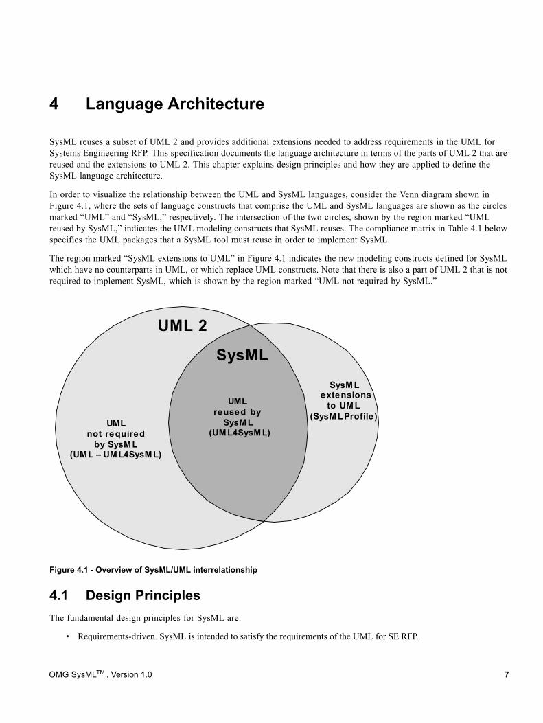
4 Language Architecture
SysML reuses a subset of UML 2 and provides additional extensions needed to address requirements in the UML for Systems Engineering RFP. This specification documents the language architecture in terms of the parts of UML 2 that are reused and the extensions to UML 2. This chapter explains design principles and how they are applied to define the SysML language architecture.
In order to visualize the relationship between the UML and SysML languages, consider the Venn diagram shown in Figure 4.1, where the sets of language constructs that comprise the UML and SysML languages are shown as the circles marked “UML” and “SysML,” respectively. The intersection of the two circles, shown by the region marked “UML reused by SysML,” indicates the UML modeling constructs that SysML reuses. The compliance matrix in Table 4.1 below specifies the UML packages that a SysML tool must reuse in order to implement SysML.
The region marked “SysML extensions to UML” in Figure 4.1 indicates the new modeling constructs defined for SysML which have no counterparts in UML, or which replace UML constructs. Note that there is also a part of UML 2 that is not required to implement SysML, which is shown by the region marked “UML not required by SysML.”
Figure 4.1 - Overview of SysML/UML interrelationship
4.1 Design PrinciplesThe fundamental design principles for SysML are:
• Requirements-driven. SysML is intended to satisfy the requirements of the UML for SE RFP.
SysML
UMLnot required
by SysML(UM L – UM L4SysM L)
UMLreused by
SysM L(UML4SysM L)
SysM Lextensions
to UM L(SysM L Profile)
UML 2
OMG SysMLTM , Version 1.0 7
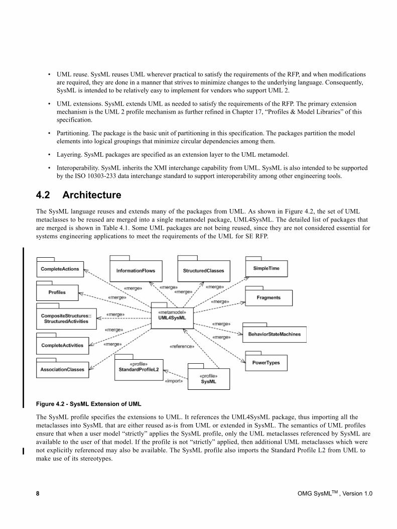
• UML reuse. SysML reuses UML wherever practical to satisfy the requirements of the RFP, and when modifications are required, they are done in a manner that strives to minimize changes to the underlying language. Consequently, SysML is intended to be relatively easy to implement for vendors who support UML 2.
• UML extensions. SysML extends UML as needed to satisfy the requirements of the RFP. The primary extension mechanism is the UML 2 profile mechanism as further refined in Chapter 17, “Profiles & Model Libraries” of this specification.
• Partitioning. The package is the basic unit of partitioning in this specification. The packages partition the model elements into logical groupings that minimize circular dependencies among them.
• Layering. SysML packages are specified as an extension layer to the UML metamodel.
• Interoperability. SysML inherits the XMI interchange capability from UML. SysML is also intended to be supported by the ISO 10303-233 data interchange standard to support interoperability among other engineering tools.
4.2 ArchitectureThe SysML language reuses and extends many of the packages from UML. As shown in Figure 4.2, the set of UML metaclasses to be reused are merged into a single metamodel package, UML4SysML. The detailed list of packages that are merged is shown in Table 4.1. Some UML packages are not being reused, since they are not considered essential for systems engineering applications to meet the requirements of the UML for SE RFP.
Figure 4.2 - SysML Extension of UML
The SysML profile specifies the extensions to UML. It references the UML4SysML package, thus importing all the metaclasses into SysML that are either reused as-is from UML or extended in SysML. The semantics of UML profiles ensure that when a user model “strictly” applies the SysML profile, only the UML metaclasses referenced by SysML are available to the user of that model. If the profile is not “strictly” applied, then additional UML metaclasses which were not explicitly referenced may also be available. The SysML profile also imports the Standard Profile L2 from UML to make use of its stereotypes.
8 OMG SysMLTM , Version 1.0
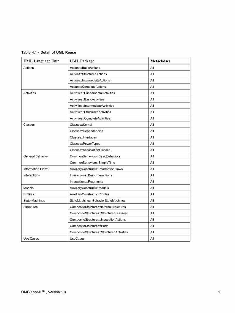
Table 4.1 - Detail of UML Reuse
UML Language Unit UML Package Metaclasses
Actions Actions::BasicActions All
Actions::StructuredActions All
Actions::IntermediateActions All
Actions::CompleteActions All
Activities Activities::FundamentalActivities All
Activities::BasicActivities All
Activities::IntermediateActivities All
Activities::StructuredActivities All
Activities::CompleteActivities All
Classes Classes::Kernel All
Classes::Dependencies All
Classes::Interfaces All
Classes::PowerTypes All
Classes::AssociationClasses All
General Behavior CommonBehaviors::BasicBehaviors All
CommonBehaviors::SimpleTime All
Information Flows AuxiliaryConstructs::InformationFlows All
Interactions Interactions::BasicInteractions All
Interactions::Fragments All
Models AuxiliaryConstructs::Models All
Profiles AuxiliaryConstructs::Profiles All
State Machines StateMachines::BehaviorStateMachines All
Structures CompositeStructures::InternalStructures All
CompositeStructures::StructuredClasses All
CompositeStructures::InvocationActions All
CompositeStructures::Ports All
CompositeStructures::StructuredActivities All
Use Cases UseCases All
OMG SysMLTM , Version 1.0 9
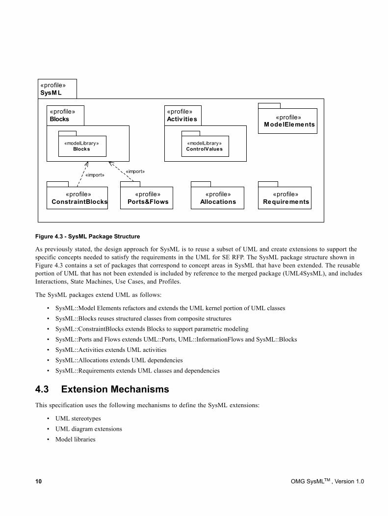
Figure 4.3 - SysML Package Structure
As previously stated, the design approach for SysML is to reuse a subset of UML and create extensions to support the specific concepts needed to satisfy the requirements in the UML for SE RFP. The SysML package structure shown in Figure 4.3 contains a set of packages that correspond to concept areas in SysML that have been extended. The reusable portion of UML that has not been extended is included by reference to the merged package (UML4SysML), and includes Interactions, State Machines, Use Cases, and Profiles.
The SysML packages extend UML as follows:
• SysML::Model Elements refactors and extends the UML kernel portion of UML classes• SysML::Blocks reuses structured classes from composite structures• SysML::ConstraintBlocks extends Blocks to support parametric modeling• SysML::Ports and Flows extends UML::Ports, UML::InformationFlows and SysML::Blocks• SysML::Activities extends UML activities • SysML::Allocations extends UML dependencies• SysML::Requirements extends UML classes and dependencies
4.3 Extension MechanismsThis specification uses the following mechanisms to define the SysML extensions:
• UML stereotypes• UML diagram extensions• Model libraries
«profile»SysM L
«profile»ConstraintBlocks
«profile»Blocks
«profile»Activ ities
«modelLibrary»Blocks
«modelLibrary»ControlValues
«profile»Ports&Flows
«profile»Requirements
«profile»Allocations
«profile»M odelElements
«import»«import»
10 OMG SysMLTM , Version 1.0
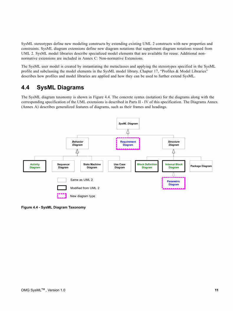
SysML stereotypes define new modeling constructs by extending existing UML 2 constructs with new properties and constraints. SysML diagram extensions define new diagram notations that supplement diagram notations reused from UML 2. SysML model libraries describe specialized model elements that are available for reuse. Additional non- normative extensions are included in Annex C: Non-normative Extensions.
The SysML user model is created by instantiating the metaclasses and applying the stereotypes specified in the SysML profile and subclassing the model elements in the SysML model library. Chapter 17, “Profiles & Model Libraries” describes how profiles and model libraries are applied and how they can be used to further extend SysML.
4.4 SysML DiagramsThe SysML diagram taxonomy is shown in Figure 4.4. The concrete syntax (notation) for the diagrams along with the corresponding specification of the UML extensions is described in Parts II - IV of this specification. The Diagrams Annex (Annex A) describes generalized features of diagrams, such as their frames and headings.
Figure 4.4 - SysML Diagram Taxonomy
SysML Diagram
StructureDiagram
BehaviorDiagram
Use CaseDiagram
ActivityDiagram
Internal Block Diagram
Block Definition Diagram
SequenceDiagram
State MachineDiagram
ParametricDiagram
RequirementDiagram
Modified from UML 2
New diagram type
Package Diagram
Same as UML 2
OMG SysMLTM , Version 1.0 11

12 OMG SysMLTM , Version 1.0
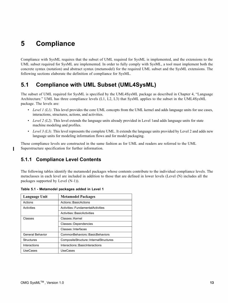
5 Compliance
Compliance with SysML requires that the subset of UML required for SysML is implemented, and the extensions to the UML subset required for SysML are implemented. In order to fully comply with SysML, a tool must implement both the concrete syntax (notation) and abstract syntax (metamodel) for the required UML subset and the SysML extensions. The following sections elaborate the definition of compliance for SysML.
5.1 Compliance with UML Subset (UML4SysML)The subset of UML required for SysML is specified by the UML4SysML package as described in Chapter 4, “Language Architecture.” UML has three compliance levels (L1, L2, L3) that SysML applies to the subset in the UML4SysML package. The levels are:
• Level 1 (L1). This level provides the core UML concepts from the UML kernel and adds language units for use cases, interactions, structures, actions, and activities.
• Level 2 (L2). This level extends the language units already provided in Level 1and adds language units for state machine modeling and profiles.
• Level 3 (L3). This level represents the complete UML. It extends the language units provided by Level 2 and adds new language units for modeling information flows and for model packaging.
These compliance levels are constructed in the same fashion as for UML and readers are referred to the UML Superstructure specification for further information.
5.1.1 Compliance Level Contents
The following tables identify the metamodel packages whose contents contribute to the individual compliance levels. The metaclasses in each level are included in addition to those that are defined in lower levels (Level (N) includes all the packages supported by Level (N-1)).
Table 5.1 - Metamodel packages added in Level 1
Language Unit Metamodel PackagesActions Actions::BasicActions
Activities Activities::FundamentalActivities
Activities::BasicActivities
Classes Classes::Kernel
Classes::Dependencies
Classes::Interfaces
General Behavior CommonBehaviors::BasicBehaviors
Structures CompositeStructure::InternalStructures
Interactions Interactions::BasicInteractions
UseCases UseCases
OMG SysMLTM , Version 1.0 13
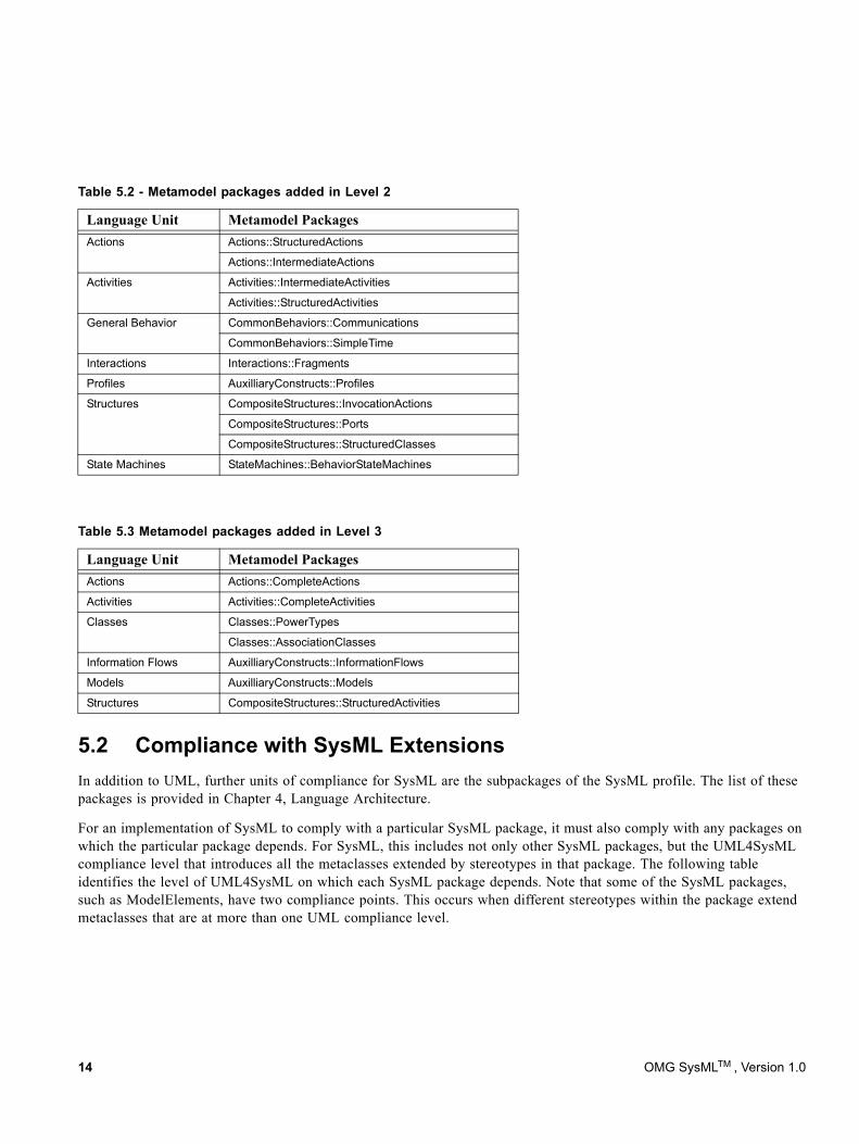
5.2 Compliance with SysML ExtensionsIn addition to UML, further units of compliance for SysML are the subpackages of the SysML profile. The list of these packages is provided in Chapter 4, Language Architecture.
For an implementation of SysML to comply with a particular SysML package, it must also comply with any packages on which the particular package depends. For SysML, this includes not only other SysML packages, but the UML4SysML compliance level that introduces all the metaclasses extended by stereotypes in that package. The following table identifies the level of UML4SysML on which each SysML package depends. Note that some of the SysML packages, such as ModelElements, have two compliance points. This occurs when different stereotypes within the package extend metaclasses that are at more than one UML compliance level.
Table 5.2 - Metamodel packages added in Level 2
Language Unit Metamodel PackagesActions Actions::StructuredActions
Actions::IntermediateActions
Activities Activities::IntermediateActivities
Activities::StructuredActivities
General Behavior CommonBehaviors::Communications
CommonBehaviors::SimpleTime
Interactions Interactions::Fragments
Profiles AuxilliaryConstructs::Profiles
Structures CompositeStructures::InvocationActions
CompositeStructures::Ports
CompositeStructures::StructuredClasses
State Machines StateMachines::BehaviorStateMachines
Table 5.3 Metamodel packages added in Level 3
Language Unit Metamodel PackagesActions Actions::CompleteActions
Activities Activities::CompleteActivities
Classes Classes::PowerTypes
Classes::AssociationClasses
Information Flows AuxilliaryConstructs::InformationFlows
Models AuxilliaryConstructs::Models
Structures CompositeStructures::StructuredActivities
14 OMG SysMLTM , Version 1.0
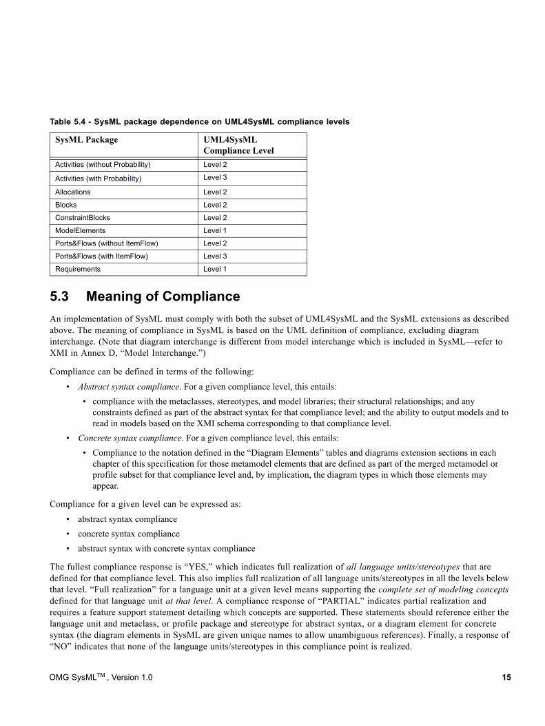
5.3 Meaning of ComplianceAn implementation of SysML must comply with both the subset of UML4SysML and the SysML extensions as described above. The meaning of compliance in SysML is based on the UML definition of compliance, excluding diagram interchange. (Note that diagram interchange is different from model interchange which is included in SysML—refer to XMI in Annex D, “Model Interchange.”)
Compliance can be defined in terms of the following:
• Abstract syntax compliance. For a given compliance level, this entails: • compliance with the metaclasses, stereotypes, and model libraries; their structural relationships; and any
constraints defined as part of the abstract syntax for that compliance level; and the ability to output models and to read in models based on the XMI schema corresponding to that compliance level.
• Concrete syntax compliance. For a given compliance level, this entails:• Compliance to the notation defined in the “Diagram Elements” tables and diagrams extension sections in each
chapter of this specification for those metamodel elements that are defined as part of the merged metamodel or profile subset for that compliance level and, by implication, the diagram types in which those elements may appear.
Compliance for a given level can be expressed as:
• abstract syntax compliance• concrete syntax compliance • abstract syntax with concrete syntax compliance
The fullest compliance response is “YES,” which indicates full realization of all language units/stereotypes that are defined for that compliance level. This also implies full realization of all language units/stereotypes in all the levels below that level. “Full realization” for a language unit at a given level means supporting the complete set of modeling concepts defined for that language unit at that level. A compliance response of “PARTIAL” indicates partial realization and requires a feature support statement detailing which concepts are supported. These statements should reference either the language unit and metaclass, or profile package and stereotype for abstract syntax, or a diagram element for concrete syntax (the diagram elements in SysML are given unique names to allow unambiguous references). Finally, a response of “NO” indicates that none of the language units/stereotypes in this compliance point is realized.
Table 5.4 - SysML package dependence on UML4SysML compliance levels
SysML Package UML4SysML Compliance Level
Activities (without Probability) Level 2
Activities (with Probability) Level 3
Allocations Level 2
Blocks Level 2
ConstraintBlocks Level 2
ModelElements Level 1
Ports&Flows (without ItemFlow) Level 2
Ports&Flows (with ItemFlow) Level 3
Requirements Level 1
OMG SysMLTM , Version 1.0 15
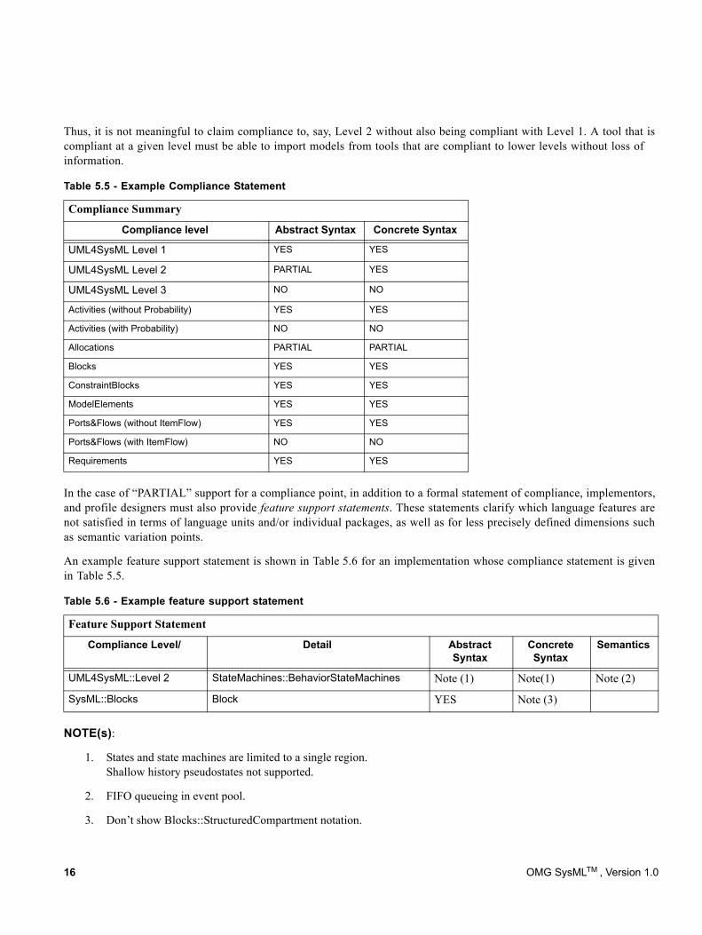
Thus, it is not meaningful to claim compliance to, say, Level 2 without also being compliant with Level 1. A tool that is compliant at a given level must be able to import models from tools that are compliant to lower levels without loss of information.
In the case of “PARTIAL” support for a compliance point, in addition to a formal statement of compliance, implementors, and profile designers must also provide feature support statements. These statements clarify which language features are not satisfied in terms of language units and/or individual packages, as well as for less precisely defined dimensions such as semantic variation points.
An example feature support statement is shown in Table 5.6 for an implementation whose compliance statement is given in Table 5.5.
NOTE(s):
1. States and state machines are limited to a single region. Shallow history pseudostates not supported.
2. FIFO queueing in event pool.
3. Don’t show Blocks::StructuredCompartment notation.
Table 5.5 - Example Compliance Statement
Compliance Summary
Compliance level Abstract Syntax Concrete Syntax
UML4SysML Level 1 YES YES
UML4SysML Level 2 PARTIAL YES
UML4SysML Level 3 NO NO
Activities (without Probability) YES YES
Activities (with Probability) NO NO
Allocations PARTIAL PARTIAL
Blocks YES YES
ConstraintBlocks YES YES
ModelElements YES YES
Ports&Flows (without ItemFlow) YES YES
Ports&Flows (with ItemFlow) NO NO
Requirements YES YES
Table 5.6 - Example feature support statement
Feature Support Statement
Compliance Level/ Detail Abstract Syntax
Concrete Syntax
Semantics
UML4SysML::Level 2 StateMachines::BehaviorStateMachines Note (1) Note(1) Note (2)
SysML::Blocks Block YES Note (3)
16 OMG SysMLTM , Version 1.0
6 Language Formalism
The SysML specification is defined by using UML 2 specification techniques. These techniques are used to achieve the following goals in the specification.
• Correctness• Precision• Conciseness• Consistency• Understandability
The specification technique used in this specification describes SysML as a UML extension that is defined using stereotypes and model libraries.
6.1 Levels of FormalismSysML is specified using a combination of UML modeling techniques and precise natural language to balance rigor and understandability. Use of more formal constraints and semantics may be applied in future versions to further increase the precision of the language.
6.2 Chapter Specification StructureThe chapters in Parts II - IV are organized according to the SysML packages as described in the language architecture and selected reusable portions of UML 2 packages. This section provides information about how each chapter is organized.
6.2.1 OverviewThis section provides an overview of the SysML modeling constructs defined in the subject package, which are usually associated with one or more SysML diagram types.
6.2.2 Diagram ElementsThis section provides tables that summarize the concrete syntax (notation) and abstract syntax references for the graphic nodes and paths associated with the relevant diagram types. The diagram elements tables are intended to include all of the diagrammatic constructs used in SysML. However, they do not represent all the different combinations in which they can be used. The reader should refer to the usage examples in the chapters and the sample problem annex (Annex B) for typical usages of the concrete syntax. General diagram information on the use of diagram frames and headings can be found in the Diagram Annex A.
The diagram elements tables and the additional usage examples fill an important role in defining the scope of SysML. As described in Chapter 4, Language Architecture, SysML imports many entire packages from the UML metamodel, which it then reuses and extends. Only a subset of the entire UML metamodel, however, is required to support the notations included in SysML.
OMG SysMLTM , Version 1.0 17
Unless a type of diagram element is shown in some form in one of the SysML diagram elements tables, or in a usage example in one of the normative SysML chapters, it is not considered to be part of the subset of UML included within SysML, even if the UML metamodel packages support additional constructs. For example, SysML imports the entire Dependencies package from UML, but it includes diagram elements for only a subset of the dependency types defined in this package.
6.2.3 UML ExtensionsThis section specifies the SysML extensions to UML in terms of diagram extensions and semantic extensions. Diagram extensions are included when the concrete syntax uses notation other than the standard stereotype notation as defined in the Profiles and Model Libraries chapter. Semantic extensions consist of stereotype and model library extensions. Stereotype extensions always include the abstract syntax that identifies which metaclasses a stereotype extends. Each stereotype includes a general description with a definition and semantics, along with stereotype properties (attributes), and constraints. The model libraries are defined as subclasses of existing metaclasses.
6.2.4 Usage ExamplesThis section shows how the SysML modeling constructs can be applied to solve systems engineering problems and is intended to reuse and/or elaborate the sample problem in Annex B.
6.3 Conventions and TypographyIn the description of SysML, the following conventions have been used:
• While referring to stereotypes, metaclasses, metaassociations, metaattributes, etc. in the text, the exact names as they appear in the model are used.
• No visibilities are presented in the diagrams, since all elements are public.
• If a section is not applicable, it is not included, except for the top-level sections outlined in Section 6.2, “Chapter Specification Structure” above
• Stereotype, metaclass, and metassociation names: initial embedded capitals are used (e.g., “ModelElement,” “ElementReference’).
• Boolean metaattribute names: always start with “is” (e.g., “isComposite”).
• Enumeration types: always end with “Kind” (e.g., “DependencyKind”).
18 OMG SysMLTM , Version 1.0
Part II - Structural Constructs
This Part defines the static and structural constructs used in SysML structure diagrams, including the package diagram, block definition diagram, internal block diagram, and parametric diagram. The structural constructs are defined in the Model Elements, Blocks, Ports and Flows, and Constraint Blocks chapters.
Chapter 7: The Model Elements chapter refactors the kernel package from UML 2 and includes some extensions to provide some foundation capabilities for model management.
Chapter 8: The Blocks chapter reuses and extends structured classes from UML 2 composite structures to provide the fundamental capability for describing system decomposition and interconnection, and to define different types of system properties including value properties with optional units of measure.
Chapter 9: The Ports and Flows chapter provides the semantics for defining how blocks and parts interact through ports and how items flow across connectors.
Chapter 10: The Constraint Blocks chapter defines how blocks are extended to be used on parametric diagrams. Parametric diagrams model a network of constraints on system properties to support engineering analysis, such as performance, reliability, and mass properties analysis.
OMG SysMLTM , Version 1.0 19

20 OMG SysMLTM , Version 1.0
7 Model Elements
7.1 OverviewThe ModelElements package of SysML defines general-purpose constructs that may be shown on multiple SysML diagram types. These include package, model, various types of dependencies (e.g., import, access, refine, realization), constraints, and comments. The package diagram defined in this chapter is used to organize the model by partitioning model elements into packageable elements and establishing dependencies between the packages and/or model elements within the package. The package defines a namespace for the packageable elements. Model elements from one package can be imported and/or accessed by another package. This organizational principle is intended to help establish unique naming of the model elements and avoid overloading a particular model element name. Packages can also be shown on other diagrams such as the block definition diagram, requirement diagram, and behavior diagrams.
Constraints are used to capture simple constraints associated with one or more model elements and can be represented on several SysML diagrams. The constraint can represent a logical constraint such as an XOR, a condition on a decision branch, or a mathematical expression. The constraint has been significantly enhanced in SysML as specified in Chapter 10, “Constraint Blocks” to enable it to be reused and parameterized to support engineering analysis.
Comments can be associated with any model element and are quite useful as an informal means of documenting the model. SysML has introduced an extension to a comment called rationale to facilitate the system modeler in capturing decisions. The rationale may be attached to any entity, such as a system element (block), or to any relationship, such as the satisfy relationship between a design element and a requirement. In the latter case, it may be used to capture the basis for the design decision and may reference an analysis report or trade study for further elaboration of the decision. In addition, SysML includes an extension of a comment to reflect a problem or issue that can be attached to any other model element.
SysML has extended the concept of view and viewpoint from UML to be consistent with the IEEE 1471 standard. In particular, a viewpoint is a specification of rules for constructing a view to address a set of stakeholder concerns, and the view is intended to represent the system from this viewpoint. This enables stakeholders to specify aspects of the system model that are important to them from their viewpoint, and then represent those aspects of the system in a specific view. Typical examples may include an operational, manufacturing, or security view/viewpoint.
7.2 Diagram ElementsMany of the diagram elements defined in this chapter, specifically comments, constraints, problem, rationale, and dependencies, including the dependency subtypes Conform, Realization, and Refine, may be shown on all SysML diagram types, in addition to the diagram elements that are specific to each diagram type.
OMG SysMLTM , Version 1.0 21
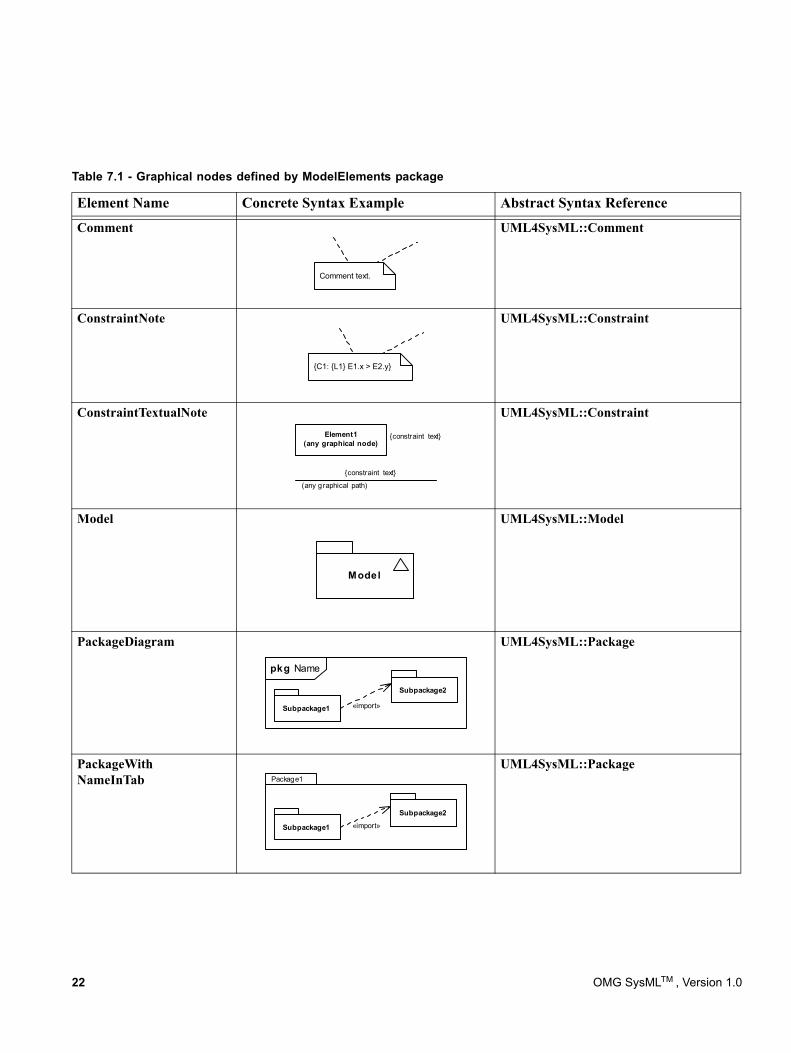
Table 7.1 - Graphical nodes defined by ModelElements package
Element Name Concrete Syntax Example Abstract Syntax Reference
Comment UML4SysML::Comment
ConstraintNote UML4SysML::Constraint
ConstraintTextualNote UML4SysML::Constraint
Model UML4SysML::Model
PackageDiagram UML4SysML::Package
PackageWith NameInTab
UML4SysML::Package
Comment text.
{C1: {L1} E1.x > E2.y}
{constraint text}
{constraint text}
(any graphical path)
Element1(any graphical node)
Model
Subpackage1
Subpackage2
«import»
pkg Name
Subpackage1
Subpackage2
Package1
«import»
22 OMG SysMLTM , Version 1.0
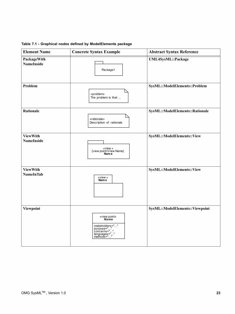
PackageWith NameInside
UML4SysML::Package
Problem SysML::ModelElements::Problem
Rationale SysML::ModelElements::Rationale
ViewWith NameInside
SysML::ModelElements::View
ViewWith NameInTab
SysML::ModelElements::View
Viewpoint SysML::ModelElements::Viewpoint
Table 7.1 - Graphical nodes defined by ModelElements package
Element Name Concrete Syntax Example Abstract Syntax Reference
Package1
«problem»The problem is that ...
«rationale»Description of rationale
«view »{view point=View Name}
Nam e
«view »Nam e
stakeholders="..."purpose="..."concerns="..."languages="..."methods="..."
«view point»Name
OMG SysMLTM , Version 1.0 23
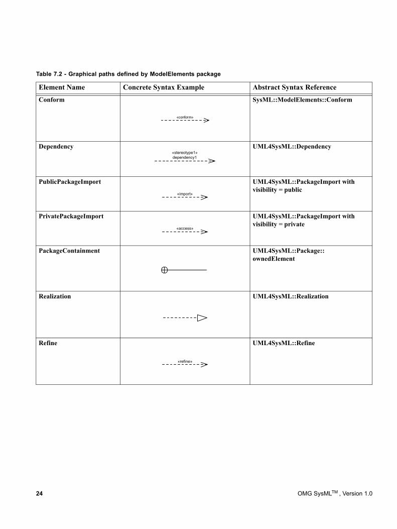
Table 7.2 - Graphical paths defined by ModelElements package
Element Name Concrete Syntax Example Abstract Syntax Reference
Conform SysML::ModelElements::Conform
Dependency UML4SysML::Dependency
PublicPackageImport UML4SysML::PackageImport with visibility = public
PrivatePackageImport UML4SysML::PackageImport with visibility = private
PackageContainment UML4SysML::Package:: ownedElement
Realization UML4SysML::Realization
Refine UML4SysML::Refine
«conform»
«stereotype1»dependency1
«import»
«access»
«refine»
24 OMG SysMLTM , Version 1.0
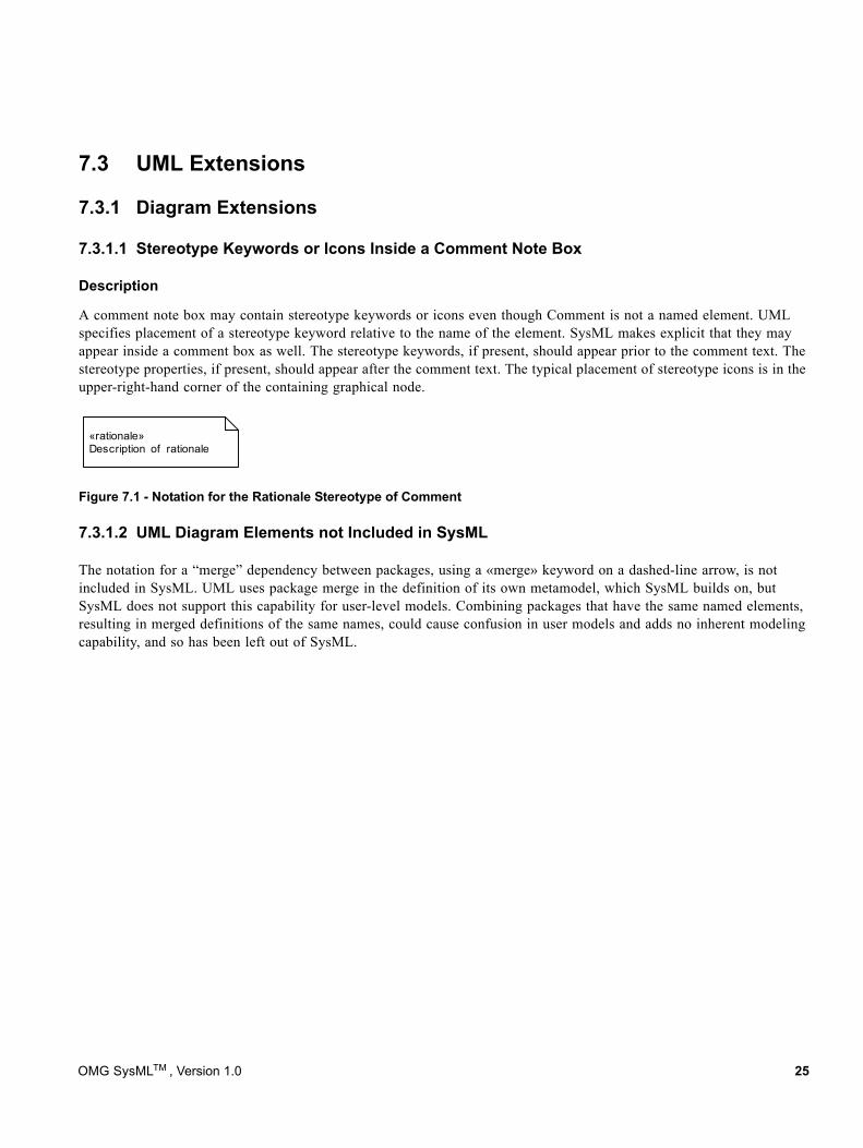
7.3 UML Extensions
7.3.1 Diagram Extensions
7.3.1.1 Stereotype Keywords or Icons Inside a Comment Note Box
Description
«rationale»Description of rationale
A comment note box may contain stereotype keywords or icons even though Comment is not a named element. UML specifies placement of a stereotype keyword relative to the name of the element. SysML makes explicit that they may appear inside a comment box as well. The stereotype keywords, if present, should appear prior to the comment text. The stereotype properties, if present, should appear after the comment text. The typical placement of stereotype icons is in the upper-right-hand corner of the containing graphical node.
Figure 7.1 - Notation for the Rationale Stereotype of Comment
7.3.1.2 UML Diagram Elements not Included in SysML
The notation for a “merge” dependency between packages, using a «merge» keyword on a dashed-line arrow, is not included in SysML. UML uses package merge in the definition of its own metamodel, which SysML builds on, but SysML does not support this capability for user-level models. Combining packages that have the same named elements, resulting in merged definitions of the same names, could cause confusion in user models and adds no inherent modeling capability, and so has been left out of SysML.
OMG SysMLTM , Version 1.0 25
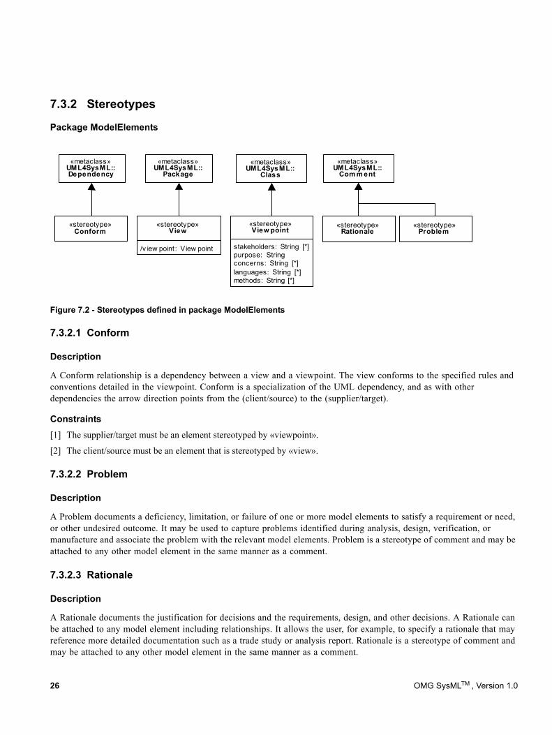
7.3.2 Stereotypes
Package ModelElements
«metaclass»UML4SysML::
Com m ent
«stereotype»Rationale
«stereotype»Problem
«metaclass»UML4SysML::
Class
stakeholders: String [*]purpose: Stringconcerns: String [*]languages: String [*]methods: String [*]
«stereotype»View point
«metaclass»UML4SysML::Dependency
«stereotype»Conform
«metaclass»UML4SysML::
Package
/v iew point : View point
«stereotype»View
7.3.2.1 Conform
Description
A Conform relationship is a dependency between a view and a viewpoint. The view conforms to the specified rules and conventions detailed in the viewpoint. Conform is a specialization of the UML dependency, and as with other dependencies the arrow direction points from the (client/source) to the (supplier/target).
Constraints[1] The supplier/target must be an element stereotyped by «viewpoint».
[2] The client/source must be an element that is stereotyped by «view».
7.3.2.2 Problem
Description
A Problem documents a deficiency, limitation, or failure of one or more model elements to satisfy a requirement or need, or other undesired outcome. It may be used to capture problems identified during analysis, design, verification, or manufacture and associate the problem with the relevant model elements. Problem is a stereotype of comment and may be attached to any other model element in the same manner as a comment.
7.3.2.3 Rationale
Description
A Rationale documents the justification for decisions and the requirements, design, and other decisions. A Rationale can be attached to any model element including relationships. It allows the user, for example, to specify a rationale that may reference more detailed documentation such as a trade study or analysis report. Rationale is a stereotype of comment and may be attached to any other model element in the same manner as a comment.
Figure 7.2 - Stereotypes defined in package ModelElements
26 OMG SysMLTM , Version 1.0
7.3.2.4 View
Description
A View is a representation of a whole system or subsystem from the perspective of a single viewpoint. Views are allowed to import other elements including other packages and other views that conform to the viewpoint.
Attributes
• /viewpoint: Viewpoint The viewpoint for this View, derived from the supplier of the «conform» dependency whose client is this View.
Constraints[1] A view can only own element import, package import, comment, and constraint elements.
[2] The view is constructed in accordance with the methods and languages that are specified as part of the viewpoint. SysML does not define the specific methods. The precise semantics of this constraint is a semantic variation point.
7.3.2.5 Viewpoint
Description
A Viewpoint is a specification of the conventions and rules for constructing and using a view for the purpose of addressing a set of stakeholder concerns. The languages and methods for specifying a view may reference languages and methods in another viewpoint. They specify the elements expected to be represented in the view, and may be formally or informally defined. For example, the security viewpoint may require the security requirements, security functional and physical architecture, and security test cases.
Attributes
• stakeholders: String [*] Set of stakeholders.
• purpose: String The purpose addresses the stakeholder concerns.
• concerns: String [*] The interest of the stakeholders.
• languages: String [*] The languages used to construct the viewpoint.
• methods: String [*] The methods used to construct the views for this viewpoint.
Constraints[1] A viewpoint cannot be the classifier of an instance specification.
[2] The property ownedOperation must be empty.
[3] The property ownedAttribute must be empty.
OMG SysMLTM , Version 1.0 27
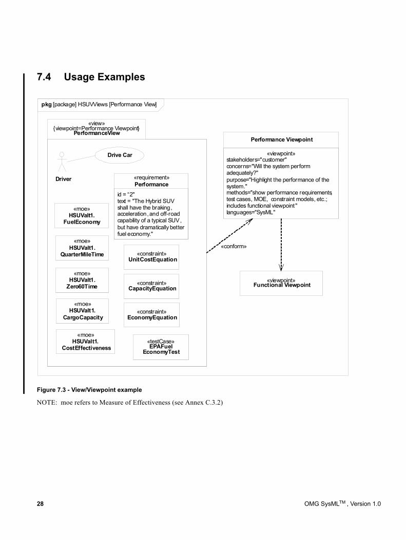
7.4 Usage Examples
Figure 7.3 - View/Viewpoint example
NOTE: moe refers to Measure of Effectiveness (see Annex C.3.2)
«view»{viewpoint=Performance Viewpoint}
PerformanceView
Driver
Drive Car
id = “2"text = "The Hybrid SUV shall have the braking, acceleration, and off-road capability of a typical SUV, but have dramatically better fuel economy."
«requirement»Performance
«moe»HSUValt1.
CostEffectiveness
«moe»HSUValt1.
FuelEconomy
«moe»HSUValt1.
Zero60Time
«moe»HSUValt1.
CargoCapacity
«moe»HSUValt1.
QuarterMileTime
«constraint»EconomyEquation
«constraint»UnitCostEquation
«constraint»CapacityEquation
«testCase»EPAFuel
EconomyTest
«viewpoint»stakeholders="customer"concerns="Will the system perform adequately?"purpose="Highlight the performance of the system."methods="show performance requirements, test cases, MOE, constraint models, etc.; includes functional viewpoint "languages="SysML"
Performance Viewpoint
«viewpoint»Functional Viewpoint
«conform»
pkg [package] HSUVViews [Performance View]
28 OMG SysMLTM , Version 1.0
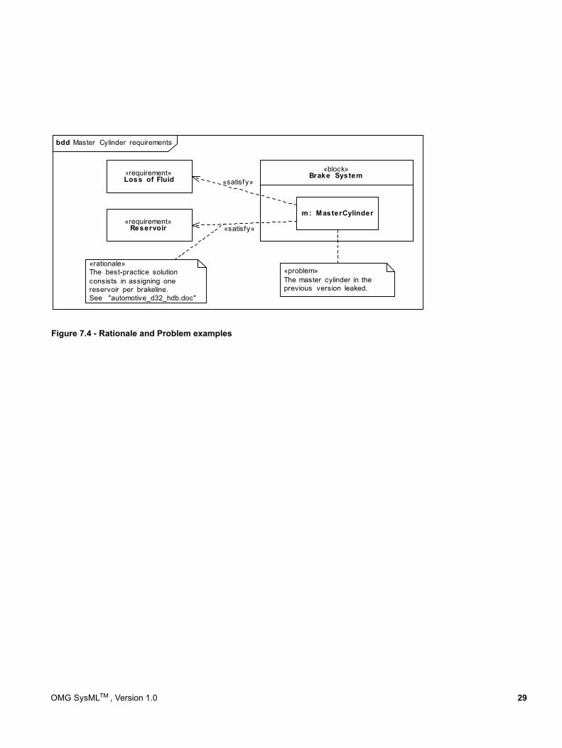
Figure 7.4 - Rationale and Problem examples
bdd Master Cylinder requirements
«requirement»Loss of Fluid
«requirement»Reservoir
«block»Brake System
m : MasterCylinder
«satisfy»
«satisfy»
«problem»The master cylinder in theprevious version leaked.
«rationale»The best-practice solutionconsists in assigning onereservoir per brakeline.See "automotive_d32_hdb.doc"
OMG SysMLTM , Version 1.0 29

30 OMG SysMLTM , Version 1.0
8 Blocks
8.1 OverviewBlocks are modular units of system description. Each block defines a collection of features to describe a system or other element of interest. These may include both structural and behavioral features, such as properties and operations, to represent the state of the system and behavior that the system may exhibit.
Blocks provide a general-purpose capability to model systems as trees of modular components. The specific kinds of components, the kinds of connections between them, and the way these elements combine to define the total system can all be selected according to the goals of a particular system model. SysML blocks can be used throughout all phases of system specification and design, and can be applied to many different kinds of systems. These include modeling either the logical or physical decomposition of a system, and the specification of software, hardware, or human elements. Parts in these systems may interact by many different means, such as software operations, discrete state transitions, flows of inputs and outputs, or continuous interactions.
The Block Definition Diagram in SysML defines features of blocks and relationships between blocks such as associations, generalizations, and dependencies. It captures the definition of blocks in terms of properties and operations, and relationships such as a system hierarchy or a system classification tree. The Internal Block Diagram in SysML captures the internal structure of a block in terms of properties and connectors between properties. A block can include properties to specify its values, parts, and references to other blocks. Ports are a special class of property used to specify allowable types of interactions between blocks, and are described in Chapter 9, “Ports and Flows.” Constraint Properties are a special class of property used to constrain other properties of blocks, and are described in Chapter 10, “Constraint Blocks.” Various notations for properties are available to distinguish these specialized kinds of properties on an internal block diagram.
A property can represent a role or usage in the context of its enclosing block. A property has a type that supplies its definition. A part belonging to a block, for example, may be typed by another block. The part defines a local usage of its defining block within the specific context to which the part belongs. For example, a block that represents the definition of a wheel can be used in different ways. The front wheel and rear wheel can represent different usages of the same wheel definition. SysML also allows each usage to define context-specific values and constraints associated with the individual usage, such as 25 psi for the front tires and 30 psi for the rear tires.
Blocks may also specify operations or other features that describe the behavior of a system. Except for operations, this chapter deals strictly with the definition of properties to describe the state of a system at any given point in time, including relations between elements that define its structure. Chapter 9, “Ports and Flows” specifies specific forms of interactions between blocks, and the Behavioral Constructs in Section III including activities, interactions, and state machines can be applied to blocks to specify their behavior. Chapter 15, “Allocations” in Part IV describes ways to allocate behavior to parts and blocks.
SysML blocks are based on UML classes as extended by UML composite structures. Some capabilities available for UML classes, such as more specialized forms of associations, have been excluded from SysML blocks to simplify the language. SysML blocks always include an ability to define internal connectors, regardless of whether this capability is needed for a particular block. SysML Blocks also extend the capabilities of UML classes and connectors with reusable forms of constraints, multi-level nesting of connector ends, participant properties for composite association classes, and connector properties. SysML blocks include several notational extensions as specified in this chapter.
OMG SysMLTM , Version 1.0 31
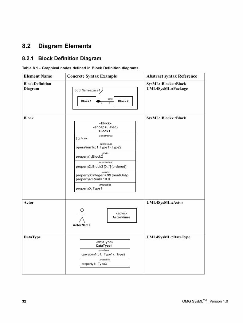
8.2 Diagram Elements
8.2.1 Block Definition Diagram
BlockDefinition Diagram bdd Namespace1
Block1 Block2part1
1 0..*
SysML::Blocks::Block UML4SysML::Package
Block
operations
parts
constraints
property1: Block2
operation1(p1: Type1): Type2
{ x > y}
«block»{encapsulated}
Block1
property5: Type1
property3: Integer = 99 {readOnly}property4: Real = 10.0
property2: Block3 [0..*] {ordered}references
values
properties
SysML::Blocks::Block
Actor UML4SysML::Actor
DataType
property1: Type3
operation1(p1: Type1): Type2
«dataType»DataType1
operations
properties
UML4SysML::DataType
Table 8.1 - Graphical nodes defined in Block Definition diagrams
Element Name Concrete Syntax Example Abstract syntax Reference
«actor»ActorNam e
ActorNam e
32 OMG SysMLTM , Version 1.0
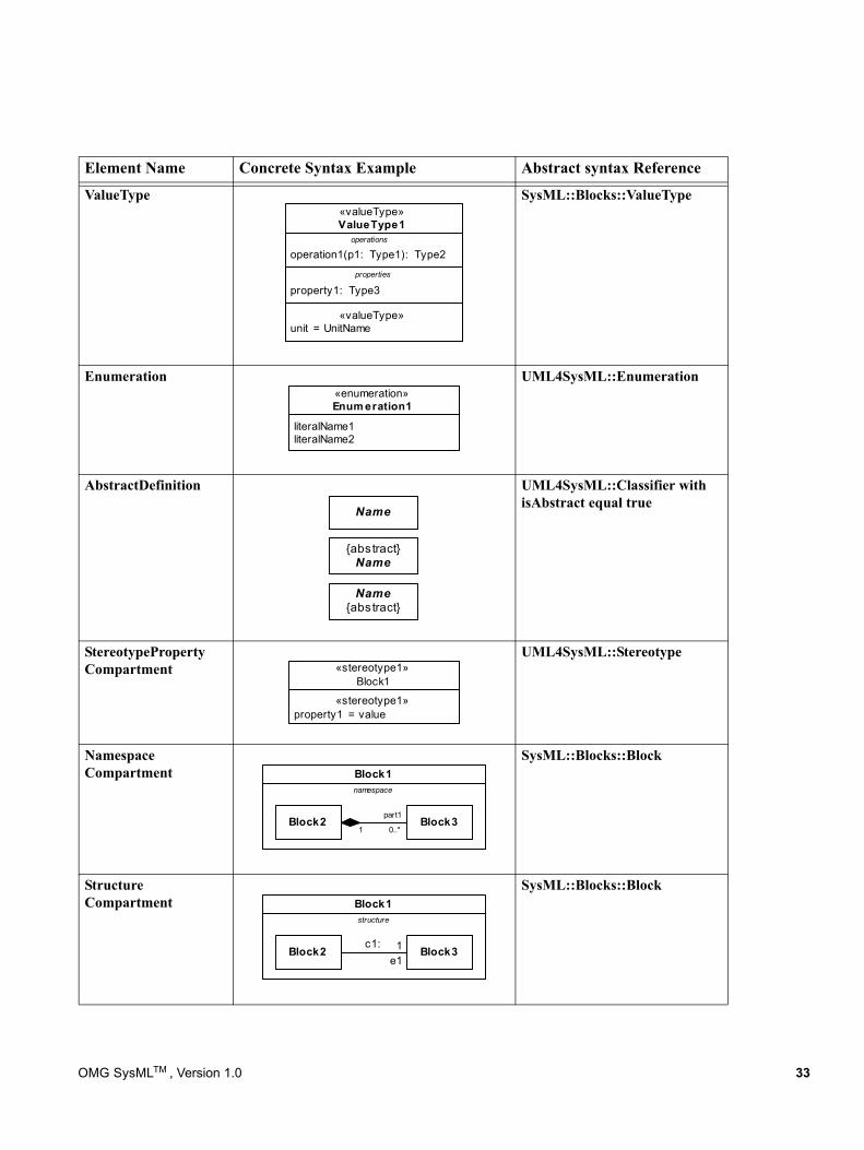
Element Name Concrete Syntax Example Abstract syntax Reference
ValueType
«valueType»unit = UnitName
property1: Type3
operation1(p1: Type1): Type2
«valueType»ValueType1
operations
properties
SysML::Blocks::ValueType
Enumeration
literalName1literalName2
«enumeration»Enum eration1
UML4SysML::Enumeration
AbstractDefinition
Name
{abstract}Name
Name{abstract}
UML4SysML::Classifier with isAbstract equal true
StereotypeProperty Compartment
«stereotype1»property1 = value
«stereotype1»Block1
UML4SysML::Stereotype
Namespace Compartment Block1
namespace
Block2 Block3part1
1 0..*
SysML::Blocks::Block
Structure Compartment Block1
structure
Block2 Block31e1
c1:
SysML::Blocks::Block
OMG SysMLTM , Version 1.0 33
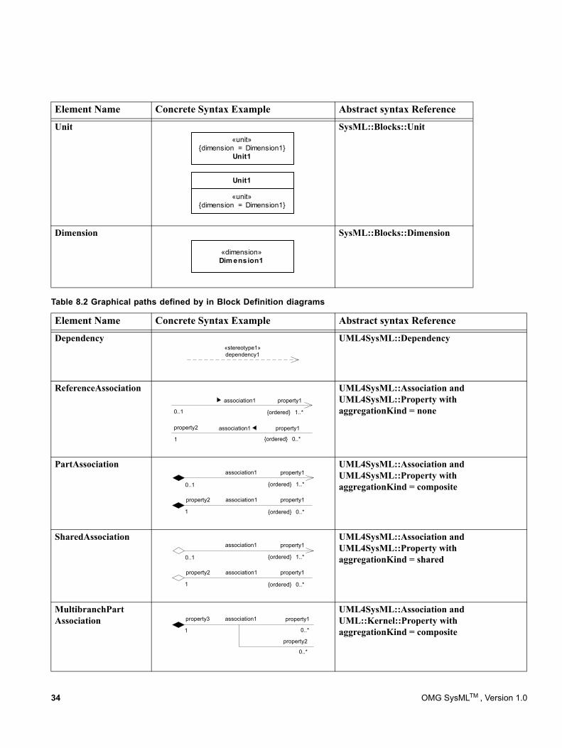
Unit«unit»
{dimension = Dimension1}Unit1
«unit»{dimension = Dimension1}
Unit1
SysML::Blocks::Unit
Dimension
«dimension»Dim ension1
SysML::Blocks::Dimension
Table 8.2 Graphical paths defined by in Block Definition diagrams
Element Name Concrete Syntax Example Abstract syntax Reference
Dependency«stereotype1»dependency1
UML4SysML::Dependency
ReferenceAssociation
0..1
association1 property1
1..*{ordered}
1
association1 property1
0..*{ordered}
property2
UML4SysML::Association and UML4SysML::Property with aggregationKind = none
PartAssociation
0..1
association1 property1
1..*{ordered}
1
association1 property1
0..*{ordered}
property2
UML4SysML::Association and UML4SysML::Property with aggregationKind = composite
SharedAssociation
0..1
association1 property1
1..*{ordered}
1
association1 property1
0..*{ordered}
property2
UML4SysML::Association and UML4SysML::Property with aggregationKind = shared
MultibranchPart Association
1
association1 property1
0..*
property3
property2
0..*
UML4SysML::Association and UML::Kernel::Property with aggregationKind = composite
Element Name Concrete Syntax Example Abstract syntax Reference
34 OMG SysMLTM , Version 1.0
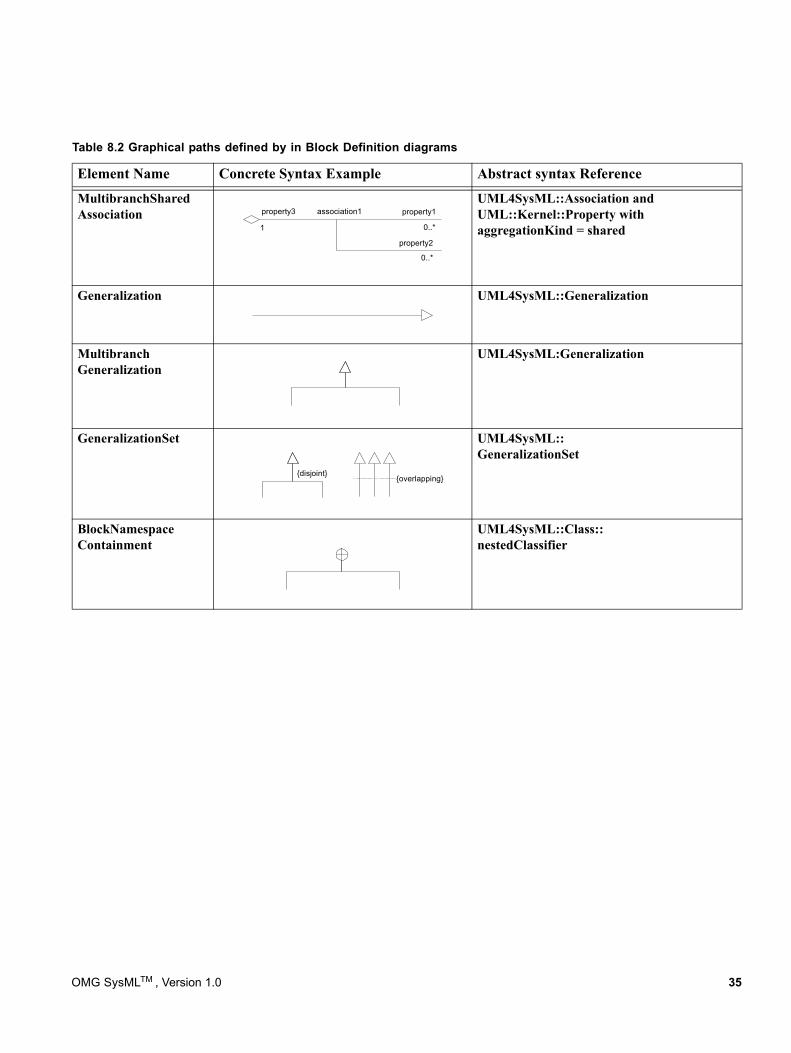
MultibranchShared Association
1
association1 property1
0..*
property3
property2
0..*
UML4SysML::Association and UML::Kernel::Property with aggregationKind = shared
Generalization UML4SysML::Generalization
Multibranch Generalization
UML4SysML:Generalization
GeneralizationSet
{disjoint}{overlapping}
UML4SysML::GeneralizationSet
BlockNamespace Containment
UML4SysML::Class:: nestedClassifier
Table 8.2 Graphical paths defined by in Block Definition diagrams
Element Name Concrete Syntax Example Abstract syntax Reference
OMG SysMLTM , Version 1.0 35
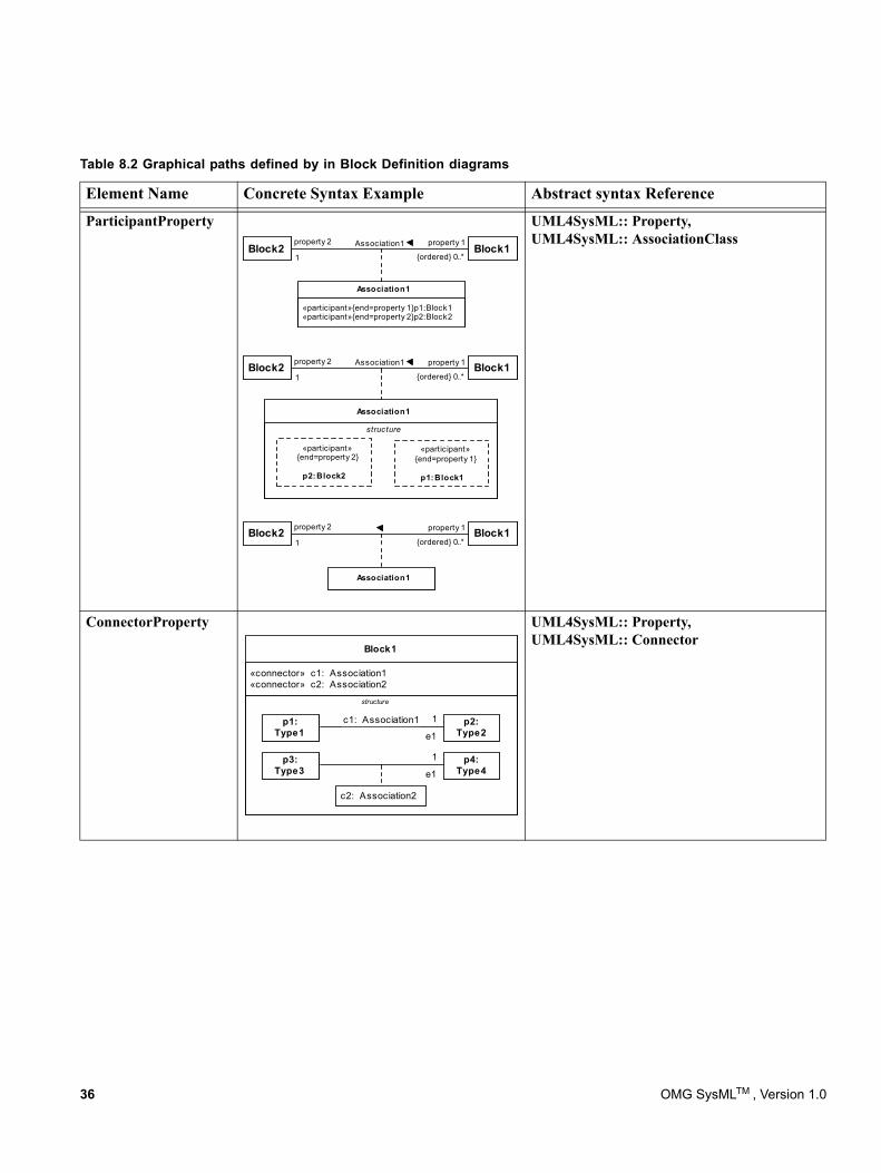
ParticipantProperty
Association1
Association1
structure
«participant»{end=property 1}
p1: Block1
«participant»{end=property 2}
p2: Block2
«participant» {end=property 1} p1: Block1«participant» {end=property 2} p2: Block2
Association1
1
Association1 property 1
0..*{ordered}
property 2 Block1Block2
1
property 1
0..*{ordered}
property 2 Block1Block2
1
Association1 property 1
0..*{ordered}
property 2Block1Block2
UML4SysML:: Property, UML4SysML:: AssociationClass
ConnectorProperty
«connector» c1: Association1«connector» c2: Association2
Block1
structure
c2: Association2
1
e1
c1: Association1
1
e1
p1:Type1
p3:Type3
p2:Type2
p4:Type4
UML4SysML:: Property, UML4SysML:: Connector
Table 8.2 Graphical paths defined by in Block Definition diagrams
Element Name Concrete Syntax Example Abstract syntax Reference
36 OMG SysMLTM , Version 1.0
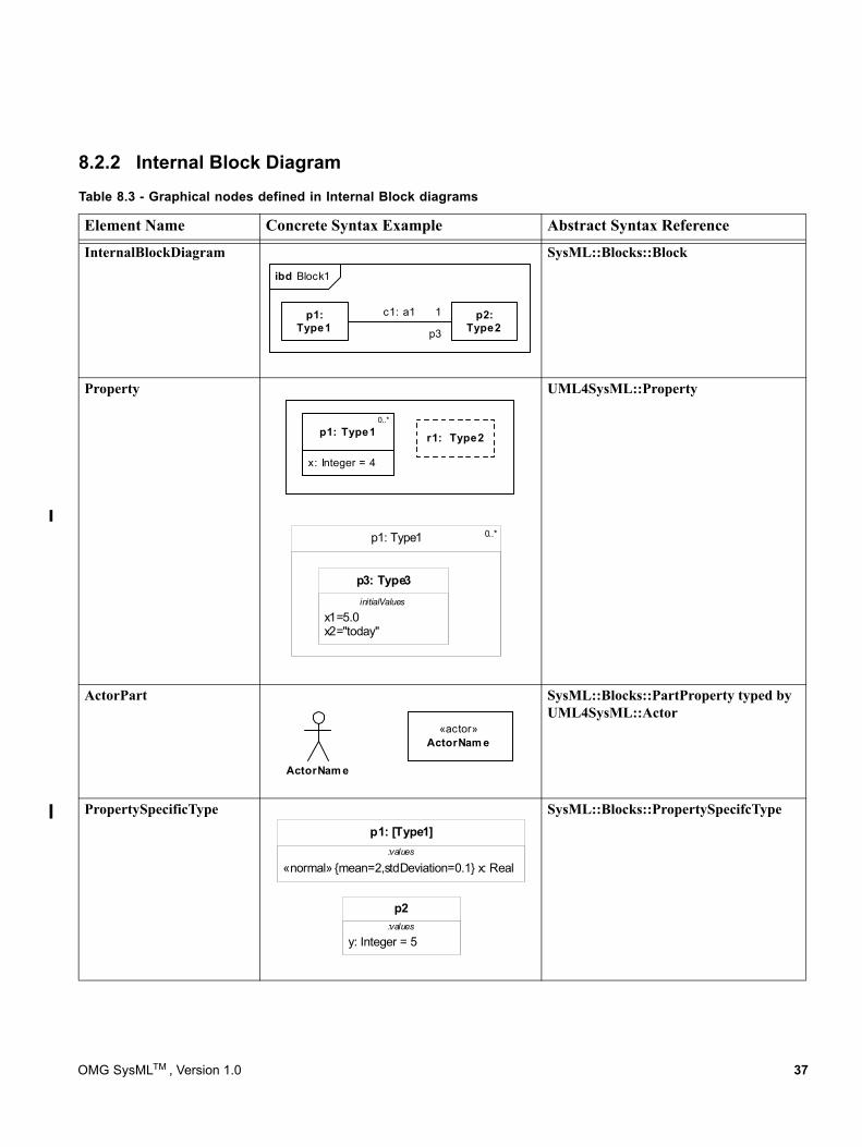
8.2.2 Internal Block Diagram
InternalBlockDiagramibd Block1
p1:Type1
p2:Type2
1
p3
c1: a1
SysML::Blocks::Block
Property
x: Integer = 4
p1: Type10..*
r1: Type2
p1: Type1
x1=5.0x2="today"
p3: Type3initialValues
0..*
UML4SysML::Property
ActorPart SysML::Blocks::PartProperty typed by UML4SysML::Actor
PropertySpecificType
y: Integer = 5
p2:values
«normal» {mean=2,stdDeviation=0.1} x: Real
p1: [Type1]:values
SysML::Blocks::PropertySpecifcType
Table 8.3 - Graphical nodes defined in Internal Block diagrams
Element Name Concrete Syntax Example Abstract Syntax Reference
«actor»ActorNam e
ActorNam e
OMG SysMLTM , Version 1.0 37
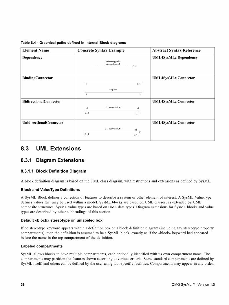
Dependency«stereotype1»dependency1
UML4SysML::Dependency
BindingConnector1 0..*
«equal»
1 1
UML4SysML::Connector
BidirectionalConnectorc1: association1
0..1 0..*
p2p1
UML4SysML::Connector
UnidirectionalConnectorc1: association1
0..1 0..*
p1
UML4SysML::Connector
8.3 UML Extensions
8.3.1 Diagram Extensions
8.3.1.1 Block Definition Diagram
A block definition diagram is based on the UML class diagram, with restrictions and extensions as defined by SysML.
Block and ValueType Definitions
A SysML Block defines a collection of features to describe a system or other element of interest. A SysML ValueType defines values that may be used within a model. SysML blocks are based on UML classes, as extended by UML composite structures. SysML value types are based on UML data types. Diagram extensions for SysML blocks and value types are described by other subheadings of this section.
Default «block» stereotype on unlabeled box
If no stereotype keyword appears within a definition box on a block definition diagram (including any stereotype property compartments), then the definition is assumed to be a SysML block, exactly as if the «block» keyword had appeared before the name in the top compartment of the definition.
Labeled compartments
SysML allows blocks to have multiple compartments, each optionally identified with its own compartment name. The compartments may partition the features shown according to various criteria. Some standard compartments are defined by SysML itself, and others can be defined by the user using tool-specific facilities. Compartments may appear in any order.
Table 8.4 - Graphical paths defined in Internal Block diagrams
Element Name Concrete Syntax Example Abstract Syntax Reference
38 OMG SysMLTM , Version 1.0
SysML defines two additional compartments, namespace and structure compartments, which may contain graphical nodes rather than textual constraint or feature definitions. See separate subsections of this section for a description of these compartments.
Constraints compartment
SysML defines a special form of compartment, with the label “constraints,” which may contain one or more constraints owned by the block. A constraint owned by the block may be shown in this compartment using the standard text-based notation for a constraint, consisting of a string enclosed in brace characters. The use of a compartment to show constraints is optional. The note-based notation, with a constraint shown in a note box outside the block and linked to it by a dashed line, may also be used to show a constraint owned by a block.
A constraints compartment may also contain declarations of constraint properties owned by the block. A constraint property is a property of the block that is typed by a ConstraintBlock, as defined in Chapter 10, “Constraint Blocks.” Only the declaration of the constraint property may be shown within the compartment, not the details of its parameters or binding connectors that link them to other properties.
Namespace compartment
A compartment with the label “namespace” may appear as part of a block definition to show blocks that are defined in the namespace of a containing block. This compartment may contain any of the graphical elements of a block definition diagram. All blocks or other named elements defined in this compartment belong to the namespace of the containing block.
Because this compartment contains graphical elements, a wider compartment than typically used for feature definitions may be useful. Since the same block can appear more than once in the same diagram, it may be useful to show this compartment as part of a separate definition box than a box that shows only feature compartments. Both namespace and structure compartments, which may both need a wide compartment to hold graphical elements, could also be shown within a common definition box.
Structure compartment
A compartment with the label “structure” may appear as part of a block definition to show connectors and other internal structure elements for the block being defined. This compartment may contain any of the graphical elements of an internal block diagram.
Because this compartment contains graphical elements, a wider compartment than typically used for feature definitions may be useful. Since the same block can appear more than once in the same diagram, it may be useful to show this compartment as part of a separate definition box than a box that shows only feature compartments. Both namespace and structure compartments, which may both need a wide compartment to hold graphical elements, could also be shown within a common definition box.
Unit and Dimension definitions
Unit and Dimension elements are defined using a rectangular box notation similar to a class, in which only the "unit" or "dimension" stereotype keyword, the name of the Unit or Dimension, and optionally the "dimension" property value of a Unit may appear. Even though the base metaclass of Unit and Dimension is InstanceSpecification, the name of a Dimension or Unit is not underlined, and no other graphical elements of a UML InstanceSpecification may be shown. The optional "dimension" property of a Unit and the "dimension" and/or "unit" properties of a ValueType are specified using standard stereotype property notations, which must refer by name to a Dimension or Unit which has already been defined separately and which is available for reference in the local namespace. A sample set of predefined dimensions and units is given in Annex C, Section C.4.
OMG SysMLTM , Version 1.0 39
Default multiplicities
SysML defines defaults for multiplicities on the ends of specific types of associations. A part or shared association has a default multiplicity of [0..1] on the black or white diamond end. A unidirectional association has a default multiplicity of
1 on its target end. These multiplicities may be assumed if not shown on a diagram. To avoid confusion, any multiplicity other than the default should always be shown on a diagram.
Property-specific type
Enclosing the type name of a property in square brackets specifies that the type is a local specialization of the referenced type, which may be overridden to specify additional values or other customizations that are unique to the property. Redefined or added features of the newly defined type may be shown in compartments for the property on an internal block diagram. If no type name appears between the square brackets, the property-specific type is defined provided by its own declarations, without specializing any existing type.
8.3.1.2 Internal Block Diagram
An internal block diagram is based on the UML composite structure diagram, with restrictions and extensions as defined by SysML.
Property types
Four general categories of properties of blocks are recognized in SysML: parts, references, value properties, and constraint properties. (See Section 8.3.2.2, Block, for definitions of these property types.) A part or value property is always shown on an internal block diagram with a solid-outline box. A reference property is shown by a dashed-outline box, consistent with UML. Ports are special cases of properties, and have a variety of notations as defined in Chapter 10, Ports and Flows. Constraint properties and their parameters also have their own notations as defined in Chapter 11, Constraint Blocks.
Block reference in diagram frame
The diagram heading name for an internal block diagram (the string contained in the tab in the upper-left-hand corner of the diagram frame) must identify the name of a SysML block as its modelElementName. (See Annex A for the definition of a diagram heading name including the modelElementName component. This component is optional for many SysML diagram types, but not for an internal block diagram.) All the properties and connectors that appear inside the internal block diagram belong to the block that is named in the diagram heading name.
Compartments on internal properties
SysML permits any property shown on an internal block diagram to also show compartments within the property box. These compartments may be given standard or user-customized labels just as on block definitions. All features shown within these compartments must match those of the block or value type that types the property. For a property-specific type, these compartments may be used to specify redefined or additional features of the locally defined type. An unlabeled compartment on an internal property box is by default a structure compartment.
The label of any compartment shown on the property box which displays contents belonging to the type of the property is shown with a colon character (":") preceding the compartment label. The compartment name is otherwise the same as would be appear on the type on a block definition diagram.
40 OMG SysMLTM , Version 1.0
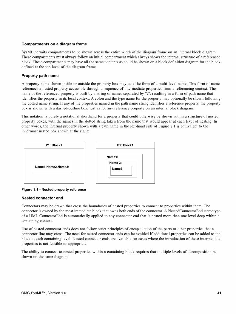
Compartments on a diagram frame
SysML permits compartments to be shown across the entire width of the diagram frame on an internal block diagram. These compartments must always follow an initial compartment which always shows the internal structure of a referenced block. These compartments may have all the same contents as could be shown on a block definition diagram for the block defined at the top level of the diagram frame.
Property path name
A property name shown inside or outside the property box may take the form of a multi-level name. This form of name references a nested property accessible through a sequence of intermediate properties from a referencing context. The name of the referenced property is built by a string of names separated by “.”, resulting in a form of path name that identifies the property in its local context. A colon and the type name for the property may optionally be shown following the dotted name string. If any of the properties named in the path name string identifies a reference property, the property box is shown with a dashed-outline box, just as for any reference property on an internal block diagram.
This notation is purely a notational shorthand for a property that could otherwise be shown within a structure of nested property boxes, with the names in the dotted string taken from the name that would appear at each level of nesting. In other words, the internal property shown with a path name in the left-hand side of Figure 8.1 is equivalent to the innermost nested box shown at the right:
Figure 8.1 - Nested property reference
Nested connector end
Connectors may be drawn that cross the boundaries of nested properties to connect to properties within them. The connector is owned by the most immediate block that owns both ends of the connector. A NestedConnectorEnd stereotype of a UML ConnectorEnd is automatically applied to any connector end that is nested more than one level deep within a containing context.
Use of nested connector ends does not follow strict principles of encapsulation of the parts or other properties that a connector line may cross. The need for nested connector ends can be avoided if additional properties can be added to the block at each containing level. Nested connector ends are available for cases where the introduction of these intermediate properties is not feasible or appropriate.
The ability to connect to nested properties within a containing block requires that multiple levels of decomposition be shown on the same diagram.
P1: Block1
Name1:
Name 2:
Name3:
P1: Block1
Name1.Name2.Name3:
OMG SysMLTM , Version 1.0 41
Property-specific type
Enclosing the type name of an internal property in square brackets specifies that the type is a local specialization of the referenced type, which may be overridden to specify additional values or other customizations that are unique to the property. Redefined or added features of the newly defined type may be shown in compartments for the property. If the property name appears on its own, with no colon or type name, or if no type name appears between the square brackets, the property-specific type is entirely provided by its own declarations, without specializing any existing type.
Initial values compartment
A compartment with a label of "initialValues" may be used to show values of properties belonging to a containing block. These values override any default values which may have been previously specified on these properties on their originally defining block. Initial value compartments may be specified within nested properties, which then apply only in the particular usage context defined by the outermost containing block.
Values are specified in an initialValues compartment by lines in the form <property-name> = <value-specification> or
<property-name> : <type> = <value-specification>, each line of which specifies the initial value for one property defined owned either by the block that types the property or by any of its supertypes. This portion of concrete syntax is the same as may be shown for values within the UML instance specification notation, but this is the only element of UML InstanceSpecification notation that may be shown. See Section 8.3.2.2 Block for details of how values within initialValues compartments are represented in the SysML metamodel.
Default multiplicities
SysML defines default multiplicities of 1 on each end of a connector. These multiplicities may be assumed if not shown on a diagram. To avoid confusion, any multiplicity other than the default should always be shown on a diagram.
8.3.1.3 UML Diagram Elements not Included in SysML Block Definition Diagrams
The supported variety of notations for associations and association annotations has been reduced to simplify the burden of teaching, learning, and interpreting SysML diagrams for the systems engineering user. Notational and metamodel support for n-ary associations and qualified associations has been excluded from SysML. N-ary associations, shown in UML by a large open diamond with multiple branches, can be modeled by an intermediate block with no loss in expressive power. Qualified associations, shown in SysML by an open box at the end of an association path with a property name inside, are a specialized feature of UML that specifies how a property value can represent an identifier of an associated target. This capability, while useful for data modeling, does not seem essential to accomplish any of the SysML requirements for support of systems engineering. The use of navigation arrowheads on an association has been simplified by excluding the case of arrowheads on both ends, and requiring that such an association always be shown without arrowheads on either end. An "X" on a single end of an association to indicate that an end is not navigable has similarly been dropped, as has the use of a small filled dot at the end of an association to indicate that the end is owned by the associated classifier.
The use of a «primitive» keyword on a value type definition (which in UML specifies the PrimitiveType specialization of UML DataType) is not supported. Whether or not a value type definition has internal structure can be determined from the value type itself.
8.3.1.4 UML Diagram Elements not Included in SysML Internal Block Diagrams
The UML Composite Structure diagram has many notations not included in the subset defined in this chapter. Other SysML chapters add some of these notations into the supported contents of an internal block diagram.
42 OMG SysMLTM , Version 1.0
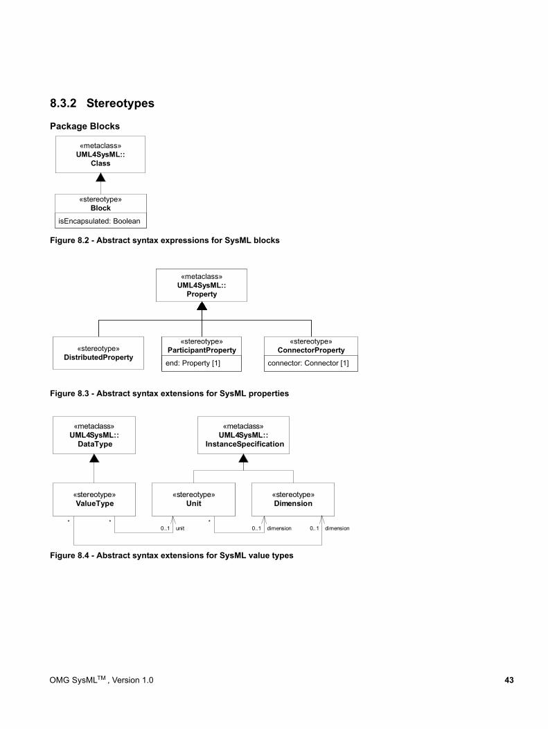
8.3.2 Stereotypes
Package Blocks
«metaclass»UML4SysML::
Class
isEncapsulated: Boolean
«stereotype»Block
«metaclass»UML4SysML::
DataType
«stereotype»ValueType
«stereotype»Unit
«stereotype»Dimension
«metaclass»UML4SysML::
InstanceSpecification
unit*
0..1 dimension*
0..1 dimension*
0..1
Figure 8.2 - Abstract syntax expressions for SysML blocks
Figure 8.3 - Abstract syntax extensions for SysML properties
Figure 8.4 - Abstract syntax extensions for SysML value types
«metaclass»UML4SysML::
Property
«stereotype»DistributedProperty
end : Property [1]
«stereotype»ParticipantProperty
connector : Connector [1]
«stereotype»ConnectorProperty
«metaclass»UML4SysML::
Property
«stereotype»DistributedProperty
end : Property [1]
«stereotype»ParticipantProperty
connector : Connector [1]
«stereotype»ConnectorProperty
«metaclass»UML4SysML::
Property
«stereotype»DistributedProperty
end : Property [1]
«stereotype»ParticipantProperty
connector : Connector [1]
«stereotype»ConnectorProperty
«metaclass»UML4SysML::
Property
«stereotype»DistributedProperty
end : Property [1]
«stereotype»ParticipantProperty
connector : Connector [1]
«stereotype»ConnectorProperty
«metaclass»UML4SysML::
Property
«stereotype»DistributedProperty
end: Property [1]
«stereotype»ParticipantProperty
connector: Connector [1]
«stereotype»ConnectorProperty
OMG SysMLTM , Version 1.0 43
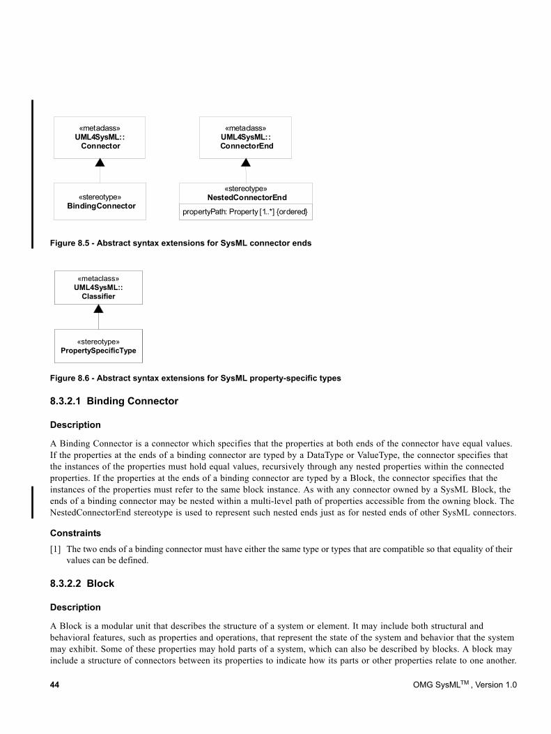
«metaclass»UML4SysML::ConnectorEnd
propertyPath: Property [1..*] {ordered}
«stereotype»NestedConnectorEnd
«metaclass»UML4SysML::
Connector
«stereotype»BindingConnector
«metaclass»UML4SysML::
Classifier
«stereotype»PropertySpecificType
Figure 8.5 - Abstract syntax extensions for SysML connector ends
Figure 8.6 - Abstract syntax extensions for SysML property-specific types
8.3.2.1 Binding Connector
Description
A Binding Connector is a connector which specifies that the properties at both ends of the connector have equal values. If the properties at the ends of a binding connector are typed by a DataType or ValueType, the connector specifies that the instances of the properties must hold equal values, recursively through any nested properties within the connected properties. If the properties at the ends of a binding connector are typed by a Block, the connector specifies that the instances of the properties must refer to the same block instance. As with any connector owned by a SysML Block, the ends of a binding connector may be nested within a multi-level path of properties accessible from the owning block. The NestedConnectorEnd stereotype is used to represent such nested ends just as for nested ends of other SysML connectors.
Constraints[1] The two ends of a binding connector must have either the same type or types that are compatible so that equality of their
values can be defined.
8.3.2.2 Block
Description
A Block is a modular unit that describes the structure of a system or element. It may include both structural and behavioral features, such as properties and operations, that represent the state of the system and behavior that the system may exhibit. Some of these properties may hold parts of a system, which can also be described by blocks. A block may include a structure of connectors between its properties to indicate how its parts or other properties relate to one another.
44 OMG SysMLTM , Version 1.0
SysML blocks provide a general-purpose capability to describe the architecture of a system. They provide the ability to represent a system hierarchy, in which a system at one level is composed of systems at a more basic level. They can describe not only the connectivity relationships between the systems at any level, but also quantitative values or other information about a system.
SysML does not restrict the kind of system or system element that may be described by a block. Any reusable form of description that may be applied to a system or a set of system characteristics may be described by a block. Such reusable descriptions, for example, may be applied to purely conceptual aspects of a system design, such as relationships that hold between parts or properties of a system.
Connectors owned by SysML blocks may be used to define relationships between parts or other properties of the same containing block. The type of a connector or its connected ends may specify the semantic interpretation of a specific connector.
SysML excludes variations of associations in UML in which navigable ends can be owned directly by the association. In SysML, navigation is equivalent to a named property owned directly by a block. The only form of an association end that SysML allows an association to own directly is an unnamed end used to carry an inverse multiplicity of a reference property. This unnamed end provides a metamodel element to record an inverse multiplicity, to cover the specific case of a unidirectional reference that defines no named property for navigation in the inverse direction. SysML enforces its equivalence of navigation and ownership by means of constraints that the block stereotype enforces on the existing UML metamodel
SysML establishes four basic classifications of properties belonging to a SysML Block or ValueType. A property typed by a SysML Block that has composite aggregation is classified as a part property, except for the special case of a constraint property. Constraint properties are further defined in Chapter 10, Constraint Blocks. A port that is typed by a Block is a special case of a part property, as further defined in Chapter 9, Ports and Flows. A property typed by a Block that does not have composite aggregation is classified as a reference property. A property typed by a UML DataType or SysML ValueType is classified as a value property, and always has composite aggregation. Part, reference, value, and constraint properties may be shown in block definition compartments with the labels "parts," "references," "values", and "constraints" respectively. Properties of any type may be shown in a "properties" compartment or in additional compartments with user-defined labels.
On a block definition diagram, a part property is shown by a black diamond symbol on an association. As in UML, an instance of a block may be included in at most one part property at a time. A part property holds instances that belong to a larger whole. Typically, a part-whole relationship means that certain operations that apply to the whole also apply to each of the parts. For example, if a whole represents a physical object, a change in position of the whole could also change the position of each of the parts. A property of the whole such as its mass could also be implied by its parts. Operations and relationships that apply to parts typically apply transitively across all parts of these parts, through any number of levels. A particular application domain may establish its own interpretation of part-whole relationships across the blocks defined in a particular model, including the definition of operations that apply to the parts along with the whole. For software objects, a typical interpretation is that delete, copy, and move operations apply across all parts of a composite object.
SysML also supports properties with shared aggregation, as shown by a white diamond symbol on an association. Like UML, SysML defines no specific semantics or constraints for properties with shared aggregation, but particular models or tools may interpret them in specific ways.
In addition to the form of default value specifications that SysML supports on properties of a block (with an optional "=" <value-specification> string following the rest of a property definition), SysML supports an additional form of value specification for properties using initialValue compartments on an internal block diagram. (See Section 8.3.1.2 Internal Block Diagram, subsection "Initial value compartments.") An entire tree of context-specific values can be specified on a containing block to carry values of nested properties as shown on an internal block diagram.
OMG SysMLTM , Version 1.0 45
Context-specific values are represented in the SysML metamodel by means of the InstanceValue subtype of UML ValueSpecification. Selected slots of UML instance specifications referenced by these instance values carry the individual values shown in initialValue compartments.
If a property belonging to a block has a specification of initial values for any of the properties belonging to its type, then the default value of that property must be a UML InstanceValue element. This element must reference a UML InstanceSpecification element created to hold the initial values of the individual properties within its usage context. The instance specification must be unnamed and owned by the same package that owns the outermost containing block for which the initial values are being specified.
Selected slots of the referenced instance specification must contain value specifications for the individual property values specified in a corresponding initialValues compartment. If a value of a property is shown by a nested property box with its own initialValues compartment, then the slot of the instance specification for the containing property must hold a new InstanceValue element. Selected slots of the instance specification referenced by this value must contain value specifications for any nested initial values, recursively through any number of levels of nesting. A tree of instance values referencing instance specifications, each of which may in turn hold slots carrying instance values, must exist until self-contained value specifications are reached at the leaf level.
Attributes
• isEncapsulated: Boolean [0..1] If true, then the block is treated as a black box; a part typed by this black box can only be connected via its ports or directly to its outer boundary. If false, or if a value is not present, then connections can be established to elements of its internal structure via deep-nested connector ends.
Constraints[1] For an association in which both ends are typed by blocks, the number of ends must be exactly two.
[2] The number of ends of a connector owned by a block must be exactly two. (In SysML, a binding connector is not typed by an association, so this constraint is not implied entirely by the preceding constraint.)
[3] In the UML metamodel on which SysML is built, any instance of the Property metaclass that is typed by a block (a Class with the «block» stereotype applied) and which is owned by an Association may not have a name and may not be defined as a navigable owned end of the association. (While the Property has a “name” property as defined by its NamedElement superclass, the value of the “name” property, which is optional, must be missing.)
[4] In the UML metamodel on which SysML is built, a Property that is typed by a block must be defined as an end of an association. (An inverse end of this association, whether owned by another block or the association itself, must always be present so there is always a metamodel element to record the inverse multiplicity of the reference.)
[5] The following constraint under Section 9.3.6, “Connector” in the UML 2 Superstructure Specification is removed by SysML: “[3] The ConnectableElements attached as roles to each ConnectorEnd owned by a Connector must be roles of the Classifier that owned the Connector, or they must be ports of such roles.”
[6] If a property owned by a SysML Block or SysML ValueType is typed by a UML DataType or SysML ValueType, then the aggregation attribute of the property must be "composite."
[7] Within an instance of a SysML Block, the values of any property with composite aggregation (aggregation = composite) must not contain the block in any of its own properties that also have composite aggregation, or within any unbroken chain of properties that all have composite aggregation. (Within an instance of a SysML Block, the instances of properties with composite aggregation must form an acyclic graph.)
[8] Any classifier which specializes a Block must also have the Block stereotype applied.
46 OMG SysMLTM , Version 1.0
8.3.2.3 ConnectorProperty
Description
Connectors can be typed by association classes that are stereotyped by Block (association blocks, see Section 8.3.2.7, “ParticipantProperty”). These connectors specify instances (links) of the association block that exist due to instantiation of the block owning or inheriting the connector. The value of a connector property on an instance of a block will be exactly those link objects that are instances of the association block typing the connector referred to by the connector property.
A connector property can optionally be shown in an internal block diagram with a dotted line from the connector line to a rectangle notating the connector property. The keyword «connector» before a property name indicates the property is stereotyped by ConnectorProperty.
Attributes
• connector : Connector A connector of the block owning the property on which the stereotype is applied.
Constraints[1] ConnectorProperty may only be applied to properties of classes stereotyped by Block.
[2] The connector attribute of the applied stereotype must refer to a connector owned or inherited by a block owning the property on which the stereotype is applied.
[3] The aggregation of a property stereotyped by ConnectorProperty must be composite.
[4] The type of the connector referred to by a connector attribute must be an association class stereotyped by Block.
[5] A property stereotyped by ConnectorProperty must have the same name and type as the connector referred to by the connector attribute.
8.3.2.4 DistributedProperty
DistributedProperty is a stereotype of Property used to apply a probability distribution to the values of the property. Specific distributions should be defined as subclasses of the DistributedProperty stereotype with the operands of the distributions represented by properties of those stereotype subclasses. A sample set of probability distributions that could be applied to value properties is given in Annex C, Section C.5, Distribution Extensions.
Constraints[1] The DistributedProperty stereotype may be applied only to properties of classifiers stereotyped by Block or ValueType.
8.3.2.5 Dimension
A Dimension is a kind of quantity that may be stated by means of defined units. For example, the dimension of length may be measured by units of meters, kilometers, or feet.
Dimension is defined as a stereotype of InstanceSpecification, but it uses this metaclass only to define supporting elements for ValueType definitions. (The reuse of InstanceSpecification to define another metaclass is similar to the EnumerationLiteral metaclass in UML.)
The only valid use of a Dimension instance is to be referenced by the “dimension” property of a ValueType or Unit stereotype.
OMG SysMLTM , Version 1.0 47
8.3.2.6 NestedConnectorEnd
Description
The NestedConnectorEnd stereotype of UML ConnectorEnd extends a UML ConnectorEnd so that the connected property may be identified by a multi-level path of accessible properties from the block that owns the connector.
Attributes
• propertyPath: Property [1..*] (ordered) The propertyPath list of the NestedConnectorEnd stereotype must identify a path of containing properties that identify the connected property in the context of the block that owns the connector. The ordering of properties is from a property of the block that owns the connector, through a property of each intermediate block that types the preceding property, until a property is reached that contains a connector end property within its type. The connector end property is not included in the propertyPath list, but instead is held by the role property of the UML ConnectorEnd metaclass.
Constraints[1] The property at the first position in the propertyPath attribute of the NestedConnectorEnd must be owned by the block that
owns the connector.
[2] The property at each successive position of the propertyPath attribute, following the first position, must be contained in the Block, DataType, or ValueType that types the property at the immediately preceding position.
[3] Within a ConnectorEnd metaclass to which the NestedConnectorEnd stereotype has been applied, the role property of the ConnectorEnd metaclass must be contained in the type of the property at the last position of the propertyPath list.
[4] Within a ConnectorEnd metaclass to which the NestedConnectorEnd stereotype has been applied, the value of the “partWithPort” property of the ConnectorEnd metaclass must be equal to the property at the last position of the propertyPath list.
8.3.2.7 ParticipantProperty
Description
The Block stereotype extends Class, so it can be applied to any specialization of Class, including Association Classes. These are informally called “association blocks.” An association block can own properties and connectors, like any other block. Each instance of an association block can link together instances of the end classifiers of the association.
To refer to linked objects and values of an instance of an association block, it is necessary for the modeler to specify which (participant) properties of the association block identify the instances being linked at which end of the association. The value of a participant property on an instance (link) of the association block is the value or object at the end of the link corresponding to this end of the association.
Participant properties can be the ends of connectors owned by an association block. The association block can be the type of multiple other connectors to reuse the same internal structure for all the connectors. The keyword «participant» before a property name indicates the property is stereotyped by ParticipantProperty. The types of participant properties can be elided if desired. They are always the same as the corresponding association end type.
Attributes
• end : Property A member end of the association block owning the property on which the stereotype is applied.
48 OMG SysMLTM , Version 1.0
Constraints[1] ParticipantProperty may only be applied to properties of association classes stereotyped by Block.
[2] ParticipantProperty may not be applied to properties that are member ends of an association.
[3] The aggregation of a property stereotyped by ParticipantProperty must be none.
[4] The end attribute of the applied stereotype must refer to a member end of the association block owning the property on which the stereotype is applied.
[5] A property stereotyped by ParticipantProperty must have the same type as the property referred to by the end attribute.
[6] The property referred to by end must have an upper multiplicity of 1.
8.3.2.8 PropertySpecificType
The PropertySpecificType stereotype is automatically applied to the classifier which types a property with a property-specific type. This classifier can contain definitions of new or redefined features which extend the original classifier referenced by the property-specific type.
Classifiers with the PropertySpecificType stereotype are owned by the block which owns the property which has the property-specific type. A classifier with this stereotype must specialize at most a single classifier which was referenced as the starting classifier of the property-specific type. If there is no starting classifier (which occurs if no existing name is specified as the starting type of a property-specific type), then a classifier with the stereotype applied has no specialization relationship from any other classifier.
Constraints[1] A classifier to which the PropertySpecificType stereotype is applied must be referenced as the type of one and only one
property.
[2] The name of a classifier to which a PropertySpecificType is applied must be missing. (The “name” attribute of the NamedElement metaclass must be empty.)
8.3.2.9 Unit
A Unit is a quantity in terms of which the magnitudes of other quantities that have the same dimension can be stated. A unit often relies on precise and reproducible ways to measure the unit. For example, a unit of length such as meter may be specified as a multiple of a particular wavelength of light. A unit may also specify less stable or precise ways to express some value, such as a cost expressed in some currency, or a severity rating measured by a numerical scale.
Unit is defined as a stereotype of InstanceSpecification, but it uses this metaclass only to define supporting elements for ValueType definitions. (The reuse of InstanceSpecification to define another metaclass is similar to the EnumerationLiteral metaclass in UML.)
The only valid use of a Unit instance is to be referenced by the “unit” property of a ValueType stereotype.
8.3.2.10 ValueType
Description
A ValueType defines types of values that may be used to express information about a system, but cannot be identified as the target of any reference. Since a value cannot be identified except by means of the value itself, each such value within a model is independent of any other, unless other forms of constraints are imposed.
OMG SysMLTM , Version 1.0 49
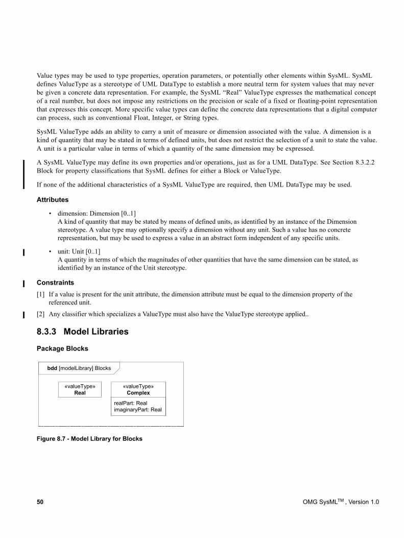
Value types may be used to type properties, operation parameters, or potentially other elements within SysML. SysML defines ValueType as a stereotype of UML DataType to establish a more neutral term for system values that may never be given a concrete data representation. For example, the SysML “Real” ValueType expresses the mathematical concept of a real number, but does not impose any restrictions on the precision or scale of a fixed or floating-point representation that expresses this concept. More specific value types can define the concrete data representations that a digital computer can process, such as conventional Float, Integer, or String types.
SysML ValueType adds an ability to carry a unit of measure or dimension associated with the value. A dimension is a kind of quantity that may be stated in terms of defined units, but does not restrict the selection of a unit to state the value. A unit is a particular value in terms of which a quantity of the same dimension may be expressed.
A SysML ValueType may define its own properties and/or operations, just as for a UML DataType. See Section 8.3.2.2 Block for property classifications that SysML defines for either a Block or ValueType.
If none of the additional characteristics of a SysML ValueType are required, then UML DataType may be used.
Attributes
• dimension: Dimension [0..1] A kind of quantity that may be stated by means of defined units, as identified by an instance of the Dimension stereotype. A value type may optionally specify a dimension without any unit. Such a value has no concrete representation, but may be used to express a value in an abstract form independent of any specific units.
• unit: Unit [0..1] A quantity in terms of which the magnitudes of other quantities that have the same dimension can be stated, as identified by an instance of the Unit stereotype.
Constraints[1] If a value is present for the unit attribute, the dimension attribute must be equal to the dimension property of the
referenced unit.
[2] Any classifier which specializes a ValueType must also have the ValueType stereotype applied..
8.3.3 Model Libraries
Package Blocks
bdd [modelLibrary] Blocks
«valueType»Real
realPart: RealimaginaryPart: Real
«valueType»Complex
Figure 8.7 - Model Library for Blocks
50 OMG SysMLTM , Version 1.0
8.3.3.1 Complex
Description
A Complex value type represents the mathematical concept of a complex number. A complex number consists of a real part defined by a real number, and an imaginary part defined by a real number multiplied by the square root of -1. Complex numbers are used to express solutions to various forms of mathematical equations.
Attributes
• realPart: Real A real number used to express the real part of a complex number.• imaginaryPart: Real A real number used to express the imaginary part of a complex number.
8.3.3.2 Real
A Real value type represents the mathematical concept of a real number. A Real value type may be used to type values that hold continuous quantities, without committing a specific representation such as a floating point data type with restrictions on precision and scale.
8.4 Usage Examples
8.4.1 Wheel Hub AssemblyIn Figure 8.8 a block definition diagram shows the blocks that comprise elements of a Wheel. The block property LugBoltJoint.torque has a specialization of DistributedProperty applied to describe the uniform distribution of its values. Examples of such distributions can be found in Section C.5.
OMG SysMLTM , Version 1.0 51
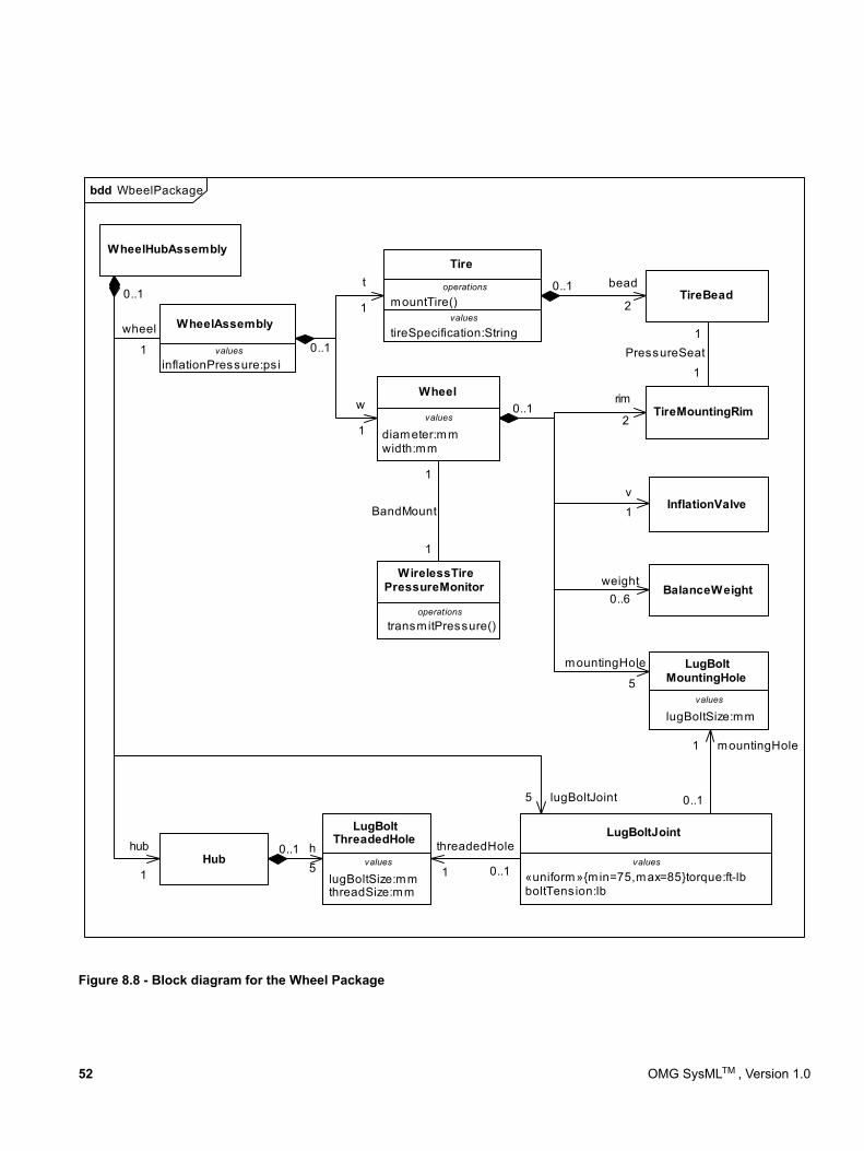
Figure 8.8 - Block diagram for the Wheel Package
WheelAssembly
diameter: mmwidth: mm
Wheel
t
1
InflationValve
BalanceWeight
lugBoltSize: mm
LugBoltMountingHole
weight0..6
mountingHole
5
v
1
TireMountingRim
TireBead
1
1
PressureSeat
bead0..12
WheelHubAssembly
rim0..1
2
lugBoltSize: mmthreadSize: mm
LugBoltThreadedHole
Hub«uniform» {m in=75, max=85} torque: ft-lbboltTens ion: lb
LugBoltJoint
0..1
1
wheel
hub
1
h0..15 1 0..1
threadedHole
1
0..1
mountingHole
lugBoltJoint5
w
0..1
1
values
inflationPressure: ps i
Tire
values
tireSpecification: String
operations
mountTire()
transmitPressure()
WirelessTirePressureMonitor
1
1
BandMount
operations
values
values
values values
bdd WbeelPackage
52 OMG SysMLTM , Version 1.0
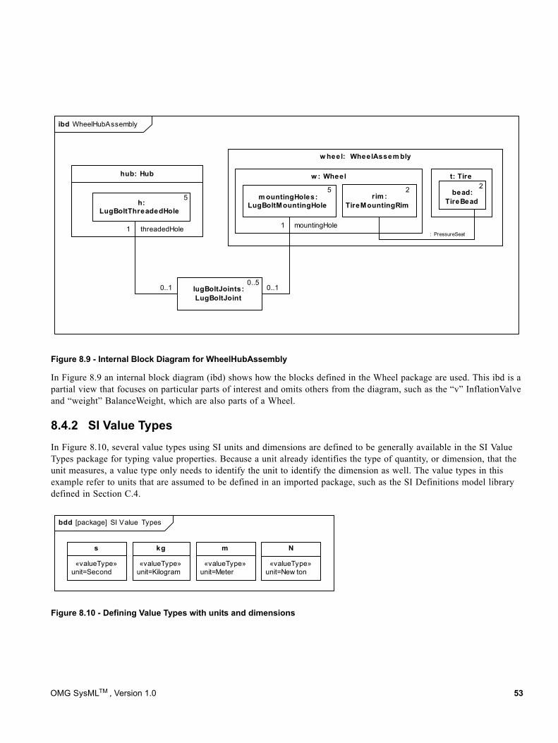
Figure 8.9 - Internal Block Diagram for WheelHubAssembly
In Figure 8.9 an internal block diagram (ibd) shows how the blocks defined in the Wheel package are used. This ibd is a partial view that focuses on particular parts of interest and omits others from the diagram, such as the “v” InflationValve and “weight” BalanceWeight, which are also parts of a Wheel.
8.4.2 SI Value TypesIn Figure 8.10, several value types using SI units and dimensions are defined to be generally available in the SI Value Types package for typing value properties. Because a unit already identifies the type of quantity, or dimension, that the unit measures, a value type only needs to identify the unit to identify the dimension as well. The value types in this example refer to units that are assumed to be defined in an imported package, such as the SI Definitions model library defined in Section C.4.
Figure 8.10 - Defining Value Types with units and dimensions
w heel: WheelAssem bly
w : Wheel
m ountingHoles:LugBoltMountingHole
5
lugBoltJoints:LugBoltJoint
t: Tire
bead:TireBead
1
0..1
mountingHole
hub: Hub
rim :TireMountingRim
: PressureSeat
0..5
22
h:LugBoltThreadedHole
1
0..1
threadedHole
5
ibd WheelHubAssembly
«valueType»unit=Second
s
«valueType»unit=New ton
N
«valueType»unit=Meter
m
«valueType»unit=Kilogram
kg
bdd [package] SI Value Types
OMG SysMLTM , Version 1.0 53
8.4.3 Design Configuration for SUV EPA Fuel Economy TestSysML internal block diagrams may be used to specify blocks with unique identification and property values. Figure 8.11 shows an example used to specify a unique vehicle with a vehicle identification number (VIN) and unique properties such as its weight, color, and horsepower. This concept is distinct from the UML concept of instance specifications in that it does not imply or assume any run-time semantic, and can also be applied to specify design configurations.
In SysML, one approach is to capture system configurations by creating a context for a configuration in the form of a context block. The context block may capture a unique identity for the configuration, and utilizes parts and initial value compartments to express property design values within the specification of a particular system configuration. Such a context block may contain a set of parts that represent the block instances in this system configuration, each containing specific values for each property. This technique also provides for configurations that reflect hierarchical system structures, where nested parts or other properties are assigned design values using initial value compartments. The following example illustrates the approach.
54 OMG SysMLTM , Version 1.0
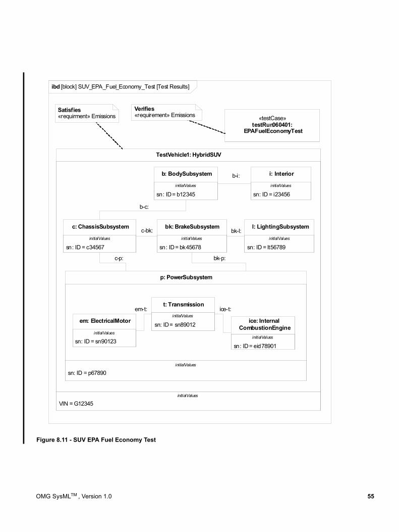
Figure 8.11 - SUV EPA Fuel Economy Test
VIN = G12345
TestVehicle1: HybridSUV
sn: ID = p67890
p: PowerSubsystem
c-bk:
b-c:
b-i:
bk-l:
c-p: bk-p:
Satisfies«requirment» Emissions
sn: ID = bk45678
bk: BrakeSubsystem
sn: ID = c34567
c: ChassisSubsystem
sn: ID = lt56789
l: LightingSubsystem
sn: ID = b12345
b: BodySubsystem
sn: ID = i23456
i: Interior
«testCase»testRun060401:
EPAFuelEconomyTest
sn: ID = sn90123
em: ElectricalMotorsn: ID = sn89012
t: Transmissionem-t: ice-t:
Verifies«requirement» Emissions
sn: ID = eid78901
ice: InternalCombustionEngine
initialValues initialValues
initialValuesinitialValuesinitialValues
initialValues
initialValuesinitialValues
initialValues
initialValues
ibd [block] SUV_EPA_Fuel_Economy_Test [Test Results]
OMG SysMLTM , Version 1.0 55
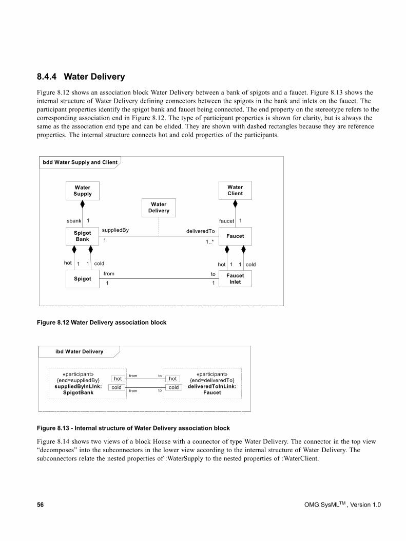
8.4.4 Water DeliveryFigure 8.12 shows an association block Water Delivery between a bank of spigots and a faucet. Figure 8.13 shows the internal structure of Water Delivery defining connectors between the spigots in the bank and inlets on the faucet. The participant properties identify the spigot bank and faucet being connected. The end property on the stereotype refers to the corresponding association end in Figure 8.12. The type of participant properties is shown for clarity, but is always the same as the association end type and can be elided. They are shown with dashed rectangles because they are reference properties. The internal structure connects hot and cold properties of the participants.
Figure 8.12 Water Delivery association block
Figure 8.13 - Internal structure of Water Delivery association block
Figure 8.14 shows two views of a block House with a connector of type Water Delivery. The connector in the top view “decomposes” into the subconnectors in the lower view according to the internal structure of Water Delivery. The subconnectors relate the nested properties of :WaterSupply to the nested properties of :WaterClient.
bdd Water Supply and Client
suppliedBy deliveredTo
1..*1
Spigot
hot hot
Faucet
WaterClient
WaterSupply
SpigotBank
1 1 1 1
from to
1 1
1 1sbank faucet
WaterDelivery
coldcold
FaucetInlet
ibd Water Delivery
«participant»{end=deliveredTo}
deliveredToInLink:Faucet
hot
cold
«participant»{end=suppliedBy}
suppliedByInLInk:SpigotBank
hot
cold
from
from
to
to
56 OMG SysMLTM , Version 1.0
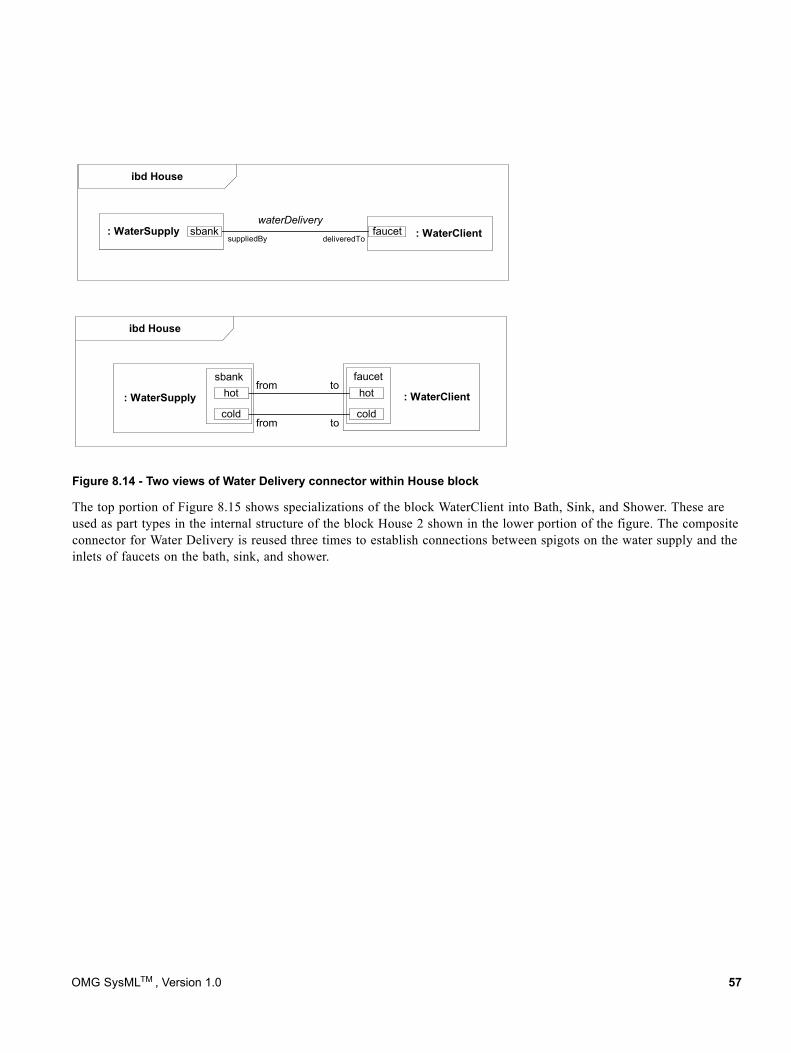
Figure 8.14 - Two views of Water Delivery connector within House block
The top portion of Figure 8.15 shows specializations of the block WaterClient into Bath, Sink, and Shower. These are used as part types in the internal structure of the block House 2 shown in the lower portion of the figure. The composite connector for Water Delivery is reused three times to establish connections between spigots on the water supply and the inlets of faucets on the bath, sink, and shower.
: WaterSupply : WaterClient
faucetsbank
: WaterSupply
ibd House
: WaterClientfaucetwaterDelivery
sbank
coldcold
hothot
ibd House
suppliedBy deliveredTo
from to
from to
OMG SysMLTM , Version 1.0 57
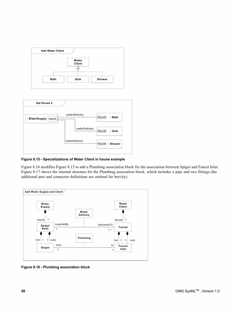
Figure 8.15 - Specializations of Water Client in house example
Figure 8.16 modifies Figure 8.12 to add a Plumbing association block for the association between Spigot and Faucet Inlet. Figure 8.17 shows the internal structure for the Plumbing association block, which includes a pipe and two fittings (the additional part and connector definitions are omitted for brevity).
Figure 8.16 - Plumbing association block
ibd House 2
: WaterSupply : BathfaucetwaterDelivery
sbank
: Sink
: Shower
waterDelivery
waterDelivery
bdd Water Client
Bath Sink Shower
WaterClient
faucet
faucet
bdd W ater Supply and Client
suppliedBy deliveredTo
1..*1
Spigot
hot
Faucet
W aterClient
W aterSupply
SpigotBank
1 1 1 1
from to
1 1
1 1sbank faucet
W aterDelivery
Plumbingcoldhot
FaucetInlet
cold
58 OMG SysMLTM , Version 1.0
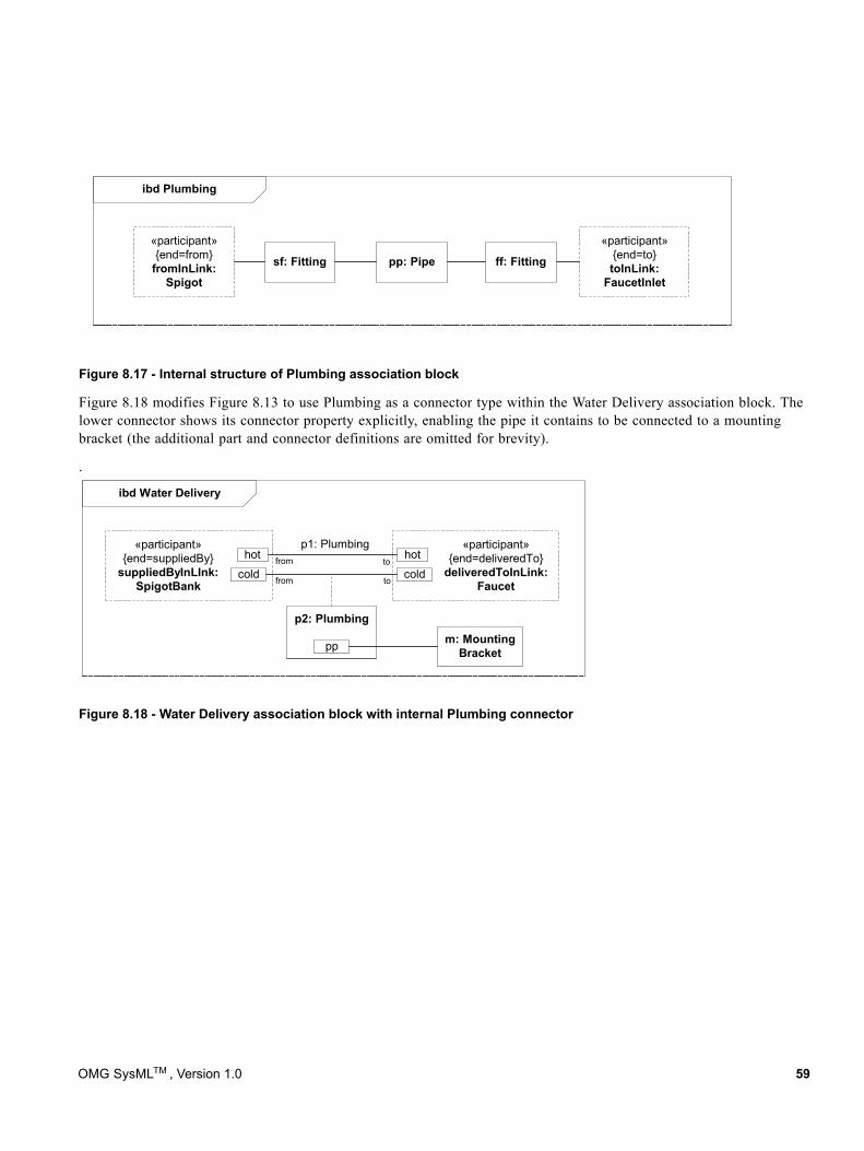
Figure 8.17 - Internal structure of Plumbing association block
Figure 8.18 modifies Figure 8.13 to use Plumbing as a connector type within the Water Delivery association block. The lower connector shows its connector property explicitly, enabling the pipe it contains to be connected to a mounting bracket (the additional part and connector definitions are omitted for brevity).
.
Figure 8.18 - Water Delivery association block with internal Plumbing connector
ibd Plumbing
«participant»{end=to}toInLink:
FaucetInlet
«participant»{end=from}
fromInLink:Spigot
pp: Pipe ff: Fittingsf: Fitting
ibd Water Delivery
«participant»{end=deliveredTo}
deliveredToInLink:Faucet
hot
cold
«participant»{end=suppliedBy}
suppliedByInLInk:SpigotBank
hot
cold
p2: Plumbing
p1: Plumbing
pp m: MountingBracket
from
from
to
to
OMG SysMLTM , Version 1.0 59

60 OMG SysMLTM , Version 1.0
9 Ports and Flows
9.1 OverviewThis chapter specifies flow ports that enable flow of items between blocks and parts, as well as standard ports that enable invocation of services on blocks and parts. A port is an interaction point between a block or part and its environment that is connected with other ports via connectors. The main motivation for specifying such ports on system elements is to allow the design of modular reusable blocks, with clearly defined interfaces. (Note: the block owns its ports and therefore the port is part of the blocks definition.) This chapter also specifies item flows across connectors and associations.
9.1.1 Standard PortsA standard port specifies the services the owning block provides (offers) to its environment as well as the services that the owning block expects (requires) of its environment. The specification of the services is achieved by typing the standard port by the provided and/or required interfaces. In general standard ports are used in the context of service-oriented components and/or architectures, either when specifying software components or applying a service-based approach to system specification. Standard ports typically contain operations which specify bidirectional flow of data, so they are typically used in the context of peer-to-peer synchronous request/reply communications. A special case of a service is signal reception, which signifies a one-way communication of signal instances, where the handling of the request is asynchronous.
A block can call operations and\or send signals through its behavioral ports that have required interfaces. A block must implement all the operations specified in its behavioral ports provided interfaces. Also, a block must react to all the signals specified in its behavioral ports provided interfaces. Non-behavioral ports delegate operations and signals to/from their internal parts over internal connectors between the non-behavioral ports and the internal parts.
For example, a block representing an automatic transmission in a car could have a standard port that specifies that the Transmission block can accept commands to switch gears. Standard ports are another name for UML 2 ports; they are defined by the same metaclass and use the same notations.
9.1.2 Flow PortsA flow port specifies the input and output items that may flow between a block and its environment. Flow ports are interaction points through which data, material, or energy can enter or leave the owning block. The specification of what can flow is achieved by typing the flow port with a specification of things that flow. This can include typing an atomic flow port with a single type representing the items that flow in or out, or typing a nonatomic flow port with a flow specification which lists multiple items that flow. A block representing an automatic transmission in a car could have an atomic flow port that specifies “Torque” as an input and another atomic flow port that specifies “Torque” as an output. A more complex flow port could specify a set of signals and/or properties that flow in and out of the flow port. In general, flow ports are intended to be used for asynchronous, broadcast, or send-and-forget interactions. Flow ports extend UML 2 ports.
9.1.3 Item FlowsItem flows represent the things that flow between blocks and/or parts and across associations or connectors. Whereas flow ports specify what “can” flow in or out of a block, item flows specify what “does” flow between blocks and/or parts in a particular usage context. This important distinction enables blocks to be interconnected in different ways depending on its usage context. For example, a tank may include a flow port that can accept fluid as an input. In a particular use of
OMG SysMLTM , Version 1.0 59
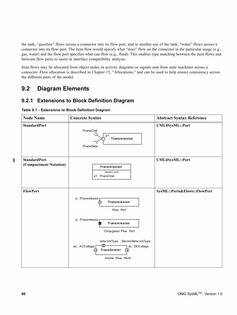
the tank, “gasoline” flows across a connector into its flow port, and in another use of the tank, “water” flows across a connector into its flow port. The item flow would specify what “does” flow on the connector in the particular usage (e.g., gas, water) and the flow port specifies what can flow (e.g., fluid). This enables type matching between the item flows and between flow ports to assist in interface compatibility analysis.
Item flows may be allocated from object nodes in activity diagrams or signals sent from state machines across a connector. Flow allocation is described in Chapter 15, “Allocations,” and can be used to help ensure consistency across the different parts of the model.
9.2 Diagram Elements
9.2.1 Extensions to Block Definition Diagram
StandardPortITransCmd
ITransData
Transm issionp1
UML4SysML::Port
StandardPort(Compartment Notation)
p1: ITransCmd
Transm issionstandard ports
UML4SysML::Port
FlowPort
Flow Port
Transm issionp: ITransmission
Conjugated Flow Port
Transm issionp: ITransmission
Atomic Flow Ports
Transform erac: ACVoltage dc: DCVoltage
netw orkType: ElectricNetw orkType
SysML::Ports&Flows::FlowPort
Table 9.1 - Extensions to Block Definition Diagram
Node Name Concrete Syntax Abstract Syntax Reference
60 OMG SysMLTM , Version 1.0
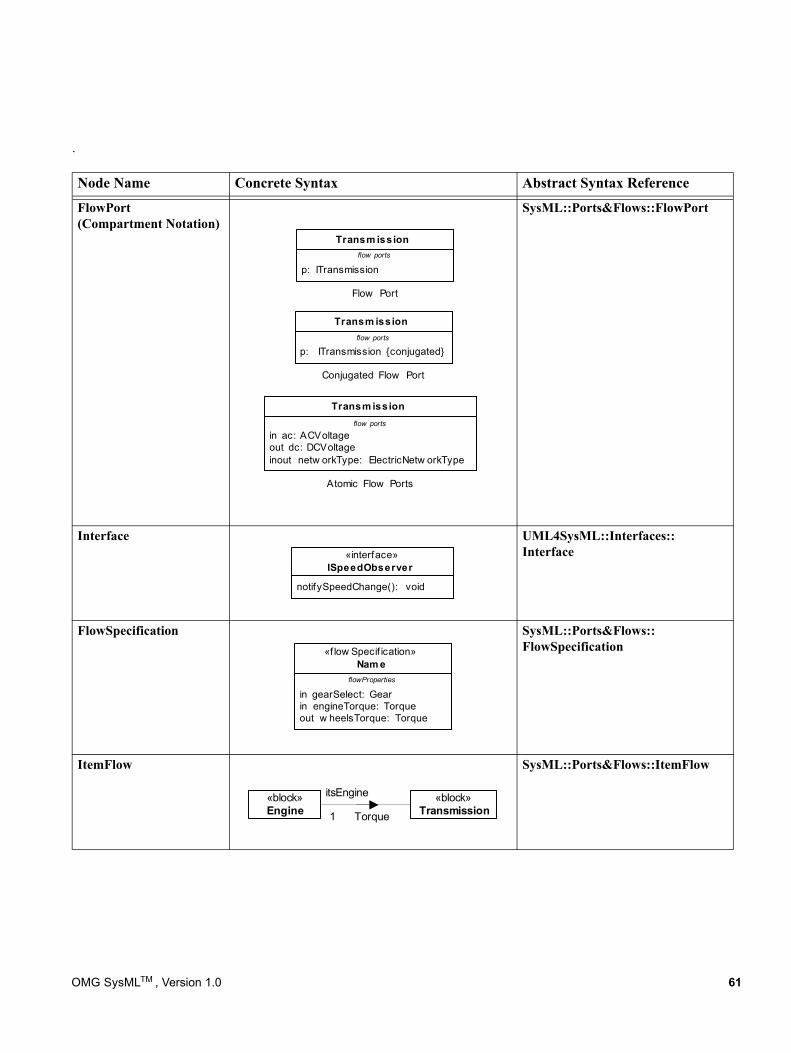
.
Node Name Concrete Syntax Abstract Syntax Reference
FlowPort(Compartment Notation)
SysML::Ports&Flows::FlowPort
Interface UML4SysML::Interfaces:: Interface
FlowSpecification SysML::Ports&Flows:: FlowSpecification
ItemFlow SysML::Ports&Flows::ItemFlow
p: ITransmission
Transm issionflow ports
Flow Port
p: ITransmission {conjugated}
Transm issionflow ports
Conjugated Flow Port
in ac: ACVoltageout dc: DCVoltageinout netw orkType: ElectricNetw orkType
Transm issionflow ports
Atomic Flow Ports
notifySpeedChange(): void
«interface»ISpeedObserver
in gearSelect: Gearin engineTorque: Torqueout w heelsTorque: Torque
«f low Specif ication»Nam e
flowProperties
«block»Engine
«block»TransmissionTorque
itsEngine
1
OMG SysMLTM , Version 1.0 61
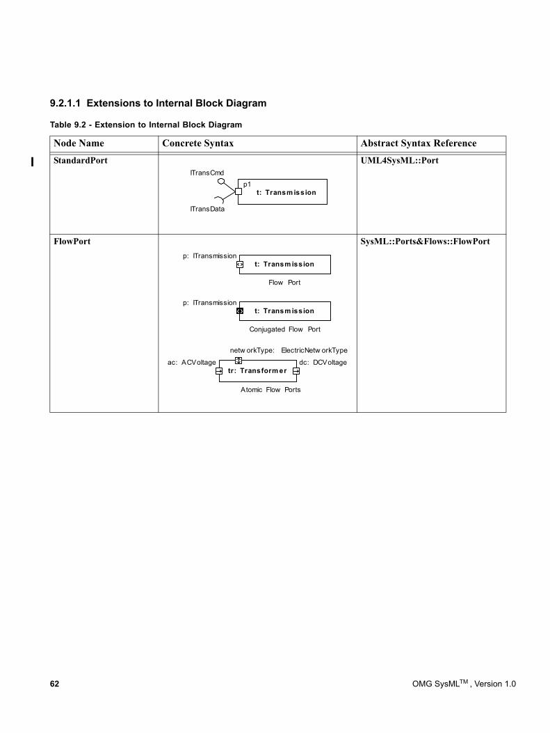
9.2.1.1 Extensions to Internal Block Diagram
Table 9.2 - Extension to Internal Block Diagram
Node Name Concrete Syntax Abstract Syntax Reference
StandardPortITransCmd
ITransData
p1t: Transm ission
UML4SysML::Port
FlowPort
Flow Port
t: Transm issionp: ITransmission
Conjugated Flow Port
t: Transm issionp: ITransmission
Atomic Flow Ports
tr: Transform erac: ACVoltage dc: DCVoltage
netw orkType: ElectricNetw orkType
SysML::Ports&Flows::FlowPort
62 OMG SysMLTM , Version 1.0
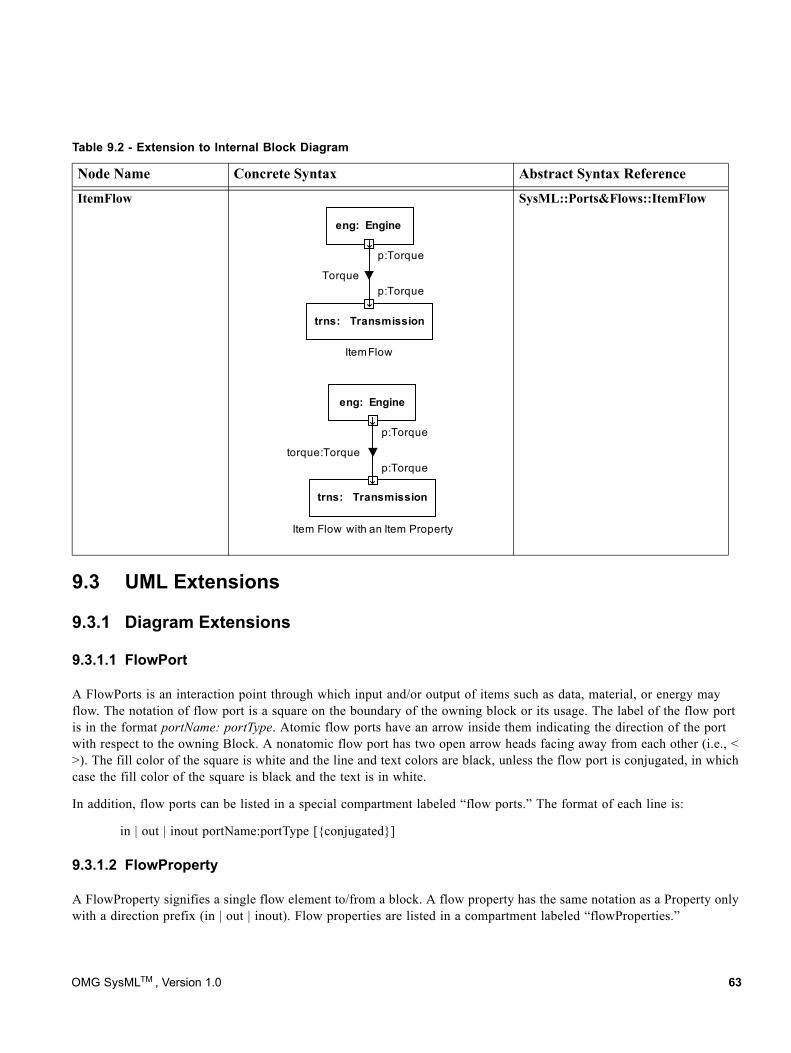
9.3 UML Extensions
9.3.1 Diagram Extensions
9.3.1.1 FlowPort
A FlowPorts is an interaction point through which input and/or output of items such as data, material, or energy may flow. The notation of flow port is a square on the boundary of the owning block or its usage. The label of the flow port is in the format portName: portType. Atomic flow ports have an arrow inside them indicating the direction of the port with respect to the owning Block. A nonatomic flow port has two open arrow heads facing away from each other (i.e., < >). The fill color of the square is white and the line and text colors are black, unless the flow port is conjugated, in which case the fill color of the square is black and the text is in white.
In addition, flow ports can be listed in a special compartment labeled “flow ports.” The format of each line is:
in | out | inout portName:portType [{conjugated}]
9.3.1.2 FlowProperty
A FlowProperty signifies a single flow element to/from a block. A flow property has the same notation as a Property only with a direction prefix (in | out | inout). Flow properties are listed in a compartment labeled “flowProperties.”
ItemFlow
Item Flow with an Item Property
eng: Engine
trns: Transmission
p: Torque
p: TorqueTorque
eng: Engine
trns: Transmission
p: Torque
p: Torquetorque: Torque
Item Flow
SysML::Ports&Flows::ItemFlow
Table 9.2 - Extension to Internal Block Diagram
Node Name Concrete Syntax Abstract Syntax Reference
OMG SysMLTM , Version 1.0 63
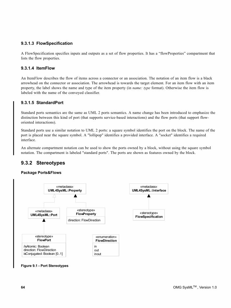
9.3.1.3 FlowSpecification
A FlowSpecification specifies inputs and outputs as a set of flow properties. It has a “flowProperties” compartment that lists the flow properties.
9.3.1.4 ItemFlow
An ItemFlow describes the flow of items across a connector or an association. The notation of an item flow is a black arrowhead on the connector or association. The arrowhead is towards the target element. For an item flow with an item property, the label shows the name and type of the item property (in name: type format). Otherwise the item flow is labeled with the name of the conveyed classifier.
9.3.1.5 StandardPort
Standard ports semantics are the same as UML 2 ports semantics. A name change has been introduced to emphasize the distinction between this kind of port (that supports service-based interactions) and the flow ports (that support flow-oriented interactions).
Standard ports use a similar notation to UML 2 ports: a square symbol identifies the port on the block. The name of the port is placed near the square symbol. A "lollipop" identifies a provided interface. A "socket" identifies a required interface.
An alternate compartment notation can be used to show the ports owned by a block, without using the square symbol notation. The compartment is labeled "standard ports". The ports are shown as features owned by the block.
9.3.2 Stereotypes
Package Ports&Flows
Figure 9.1 - Port Stereotypes
«metaclass»UML4SysML::Property
«metaclass»UML4SysML::Interface
«stereotype»FlowSpecification
direction: FlowDirection
«stereotype»FlowProperty
inoutinout
«enumeration»FlowDirection
«metaclass»UML4SysML::Port
/isAtomic: Booleandirection: FlowDirectionisConjugated: Boolean [0..1]
«stereotype»FlowPort
64 OMG SysMLTM , Version 1.0
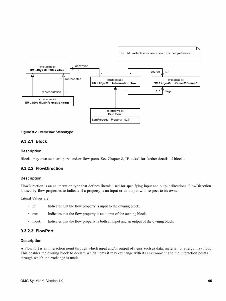
Figure 9.2 - ItemFlow Stereotype
9.3.2.1 Block
Description
Blocks may own standard ports and/or flow ports. See Chapter 8, “Blocks” for further details of blocks.
9.3.2.2 FlowDirection
Description
FlowDirection is an enumeration type that defines literals used for specifying input and output directions. FlowDirection is used by flow properties to indicate if a property is an input or an output with respect to its owner.
Literal Values are
• in: Indicates that the flow property is input to the owning block.
• out: Indicates that the flow property is an output of the owning block.
• inout: Indicates that the flow property is both an input and an output of the owning block.
9.3.2.3 FlowPort
Description
A FlowPort is an interaction point through which input and/or output of items such as data, material, or energy may flow. This enables the owning block to declare which items it may exchange with its environment and the interaction points through which the exchange is made.
The UML metaclasses are show n for completeness.
«metaclass»UML4SysML::Classifier
«metaclass»UML4SysML::Inform ationItem
*
representation *
represented «metaclass»UML4SysML::Inform ationFlow
itemProperty: Property [0..1]
«stereotype»Item Flow
«metaclass»UM L4SysM L::NamedElement
1..** target
1..**
source1..**
conveyed
OMG SysMLTM , Version 1.0 65
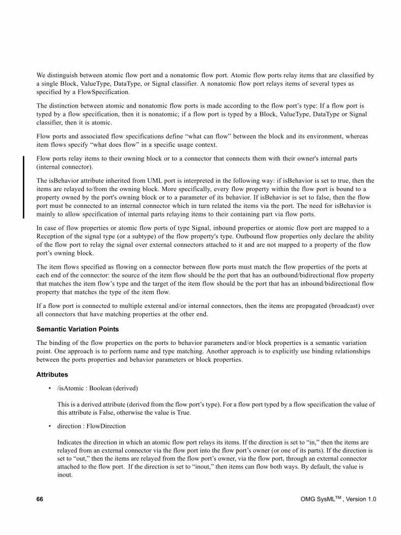
We distinguish between atomic flow port and a nonatomic flow port. Atomic flow ports relay items that are classified by a single Block, ValueType, DataType, or Signal classifier. A nonatomic flow port relays items of several types as specified by a FlowSpecification.
The distinction between atomic and nonatomic flow ports is made according to the flow port’s type: If a flow port is typed by a flow specification, then it is nonatomic; if a flow port is typed by a Block, ValueType, DataType or Signal classifier, then it is atomic.
Flow ports and associated flow specifications define “what can flow” between the block and its environment, whereas item flows specify “what does flow” in a specific usage context.
Flow ports relay items to their owning block or to a connector that connects them with their owner's internal parts (internal connector).
The isBehavior attribute inherited from UML port is interpreted in the following way: if isBehavior is set to true, then the items are relayed to/from the owning block. More specifically, every flow property within the flow port is bound to a property owned by the port's owning block or to a parameter of its behavior. If isBehavior is set to false, then the flow port must be connected to an internal connector which in turn related the items via the port. The need for isBehavior is mainly to allow specification of internal parts relaying items to their containing part via flow ports.
In case of flow properties or atomic flow ports of type Signal, inbound properties or atomic flow port are mapped to a Reception of the signal type (or a subtype) of the flow property's type. Outbound flow properties only declare the ability of the flow port to relay the signal over external connectors attached to it and are not mapped to a property of the flow port’s owning block.
The item flows specified as flowing on a connector between flow ports must match the flow properties of the ports at each end of the connector: the source of the item flow should be the port that has an outbound/bidirectional flow property that matches the item flow’s type and the target of the item flow should be the port that has an inbound/bidirectional flow property that matches the type of the item flow.
If a flow port is connected to multiple external and/or internal connectors, then the items are propagated (broadcast) over all connectors that have matching properties at the other end.
Semantic Variation Points
The binding of the flow properties on the ports to behavior parameters and/or block properties is a semantic variation point. One approach is to perform name and type matching. Another approach is to explicitly use binding relationships between the ports properties and behavior parameters or block properties.
Attributes
• /isAtomic : Boolean (derived) This is a derived attribute (derived from the flow port’s type). For a flow port typed by a flow specification the value of this attribute is False, otherwise the value is True.
• direction : FlowDirection Indicates the direction in which an atomic flow port relays its items. If the direction is set to “in,” then the items are relayed from an external connector via the flow port into the flow port’s owner (or one of its parts). If the direction is set to “out,” then the items are relayed from the flow port’s owner, via the flow port, through an external connector attached to the flow port. If the direction is set to “inout,” then items can flow both ways. By default, the value is inout.
66 OMG SysMLTM , Version 1.0
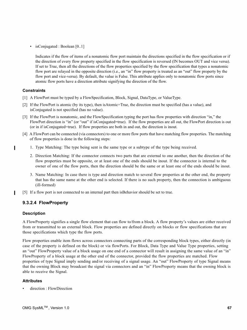
• isConjugated : Boolean [0..1] Indicates if the flow of items of a nonatomic flow port maintain the directions specified in the flow specification or if the direction of every flow property specified in the flow specification is reversed (IN becomes OUT and vice versa). If set to True, then all the directions of the flow properties specified by the flow specification that types a nonatomic flow port are relayed in the opposite direction (i.e., an “in” flow property is treated as an “out” flow property by the flow port and vice-versa). By default, the value is False. This attribute applies only to nonatomic flow ports since atomic flow ports have a direction attribute signifying the direction of the flow.
Constraints[1] A FlowPort must be typed by a FlowSpecification, Block, Signal, DataType, or ValueType.
[2] If the FlowPort is atomic (by its type), then isAtomic=True, the direction must be specified (has a value), and isConjugated is not specified (has no value).
[3] If the FlowPort is nonatomic, and the FlowSpecification typing the port has flow properties with direction “in,” the FlowPort direction is “in” (or “out” if isConjugated=true). If the flow properties are all out, the FlowPort direction is out (or in if isConjugated=true). If flow properties are both in and out, the direction is inout.
[4] A FlowPort can be connected (via connectors) to one or more flow ports that have matching flow properties. The matching of flow properties is done in the following steps:
1. Type Matching: The type being sent is the same type or a subtype of the type being received.
2. Direction Matching: If the connector connects two parts that are external to one another, then the direction of the flow properties must be opposite, or at least one of the ends should be inout. If the connector is internal to the owner of one of the flow ports, then the direction should be the same or at least one of the ends should be inout.
3. Name Matching: In case there is type and direction match to several flow properties at the other end, the property that has the same name at the other end is selected. If there is no such property, then the connection is ambiguous (ill-formed)
[5] If a flow port is not connected to an internal part then isBehavior should be set to true.
9.3.2.4 FlowProperty
Description
A FlowProperty signifies a single flow element that can flow to/from a block. A flow property’s values are either received from or transmitted to an external block. Flow properties are defined directly on blocks or flow specifications that are those specifications which type the flow ports.
Flow properties enable item flows across connectors connecting parts of the corresponding block types, either directly (in case of the property is defined on the block) or via flowPorts. For Block, Data Type and Value Type properties, setting an “out” FlowProperty value of a block usage on one end of a connector will result in assigning the same value of an “in” FlowProperty of a block usage at the other end of the connector, provided the flow properties are matched. Flow properties of type Signal imply sending and/or receiving of a signal usage. An “out” FlowProperty of type Signal means that the owning Block may broadcast the signal via connectors and an “in” FlowProperty means that the owning block is able to receive the Signal.
Attributes
• direction : FlowDirection
OMG SysMLTM , Version 1.0 67
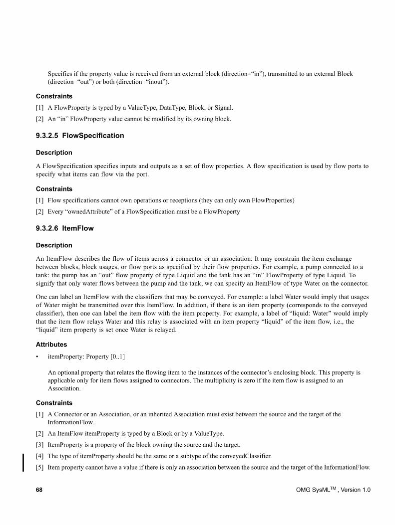
Specifies if the property value is received from an external block (direction=“in”), transmitted to an external Block (direction=“out”) or both (direction=“inout”).
Constraints[1] A FlowProperty is typed by a ValueType, DataType, Block, or Signal.
[2] An “in” FlowProperty value cannot be modified by its owning block.
9.3.2.5 FlowSpecification
Description
A FlowSpecification specifies inputs and outputs as a set of flow properties. A flow specification is used by flow ports to specify what items can flow via the port.
Constraints[1] Flow specifications cannot own operations or receptions (they can only own FlowProperties)
[2] Every “ownedAttribute” of a FlowSpecification must be a FlowProperty
9.3.2.6 ItemFlow
Description
An ItemFlow describes the flow of items across a connector or an association. It may constrain the item exchange between blocks, block usages, or flow ports as specified by their flow properties. For example, a pump connected to a tank: the pump has an “out” flow property of type Liquid and the tank has an “in” FlowProperty of type Liquid. To signify that only water flows between the pump and the tank, we can specify an ItemFlow of type Water on the connector.
One can label an ItemFlow with the classifiers that may be conveyed. For example: a label Water would imply that usages of Water might be transmitted over this ItemFlow. In addition, if there is an item property (corresponds to the conveyed classifier), then one can label the item flow with the item property. For example, a label of “liquid: Water” would imply that the item flow relays Water and this relay is associated with an item property “liquid” of the item flow, i.e., the “liquid” item property is set once Water is relayed.
Attributes
• itemProperty: Property [0..1] An optional property that relates the flowing item to the instances of the connector’s enclosing block. This property is applicable only for item flows assigned to connectors. The multiplicity is zero if the item flow is assigned to an Association.
Constraints[1] A Connector or an Association, or an inherited Association must exist between the source and the target of the
InformationFlow.
[2] An ItemFlow itemProperty is typed by a Block or by a ValueType.
[3] ItemProperty is a property of the block owning the source and the target.
[4] The type of itemProperty should be the same or a subtype of the conveyedClassifier.
[5] Item property cannot have a value if there is only an association between the source and the target of the InformationFlow.
68 OMG SysMLTM , Version 1.0
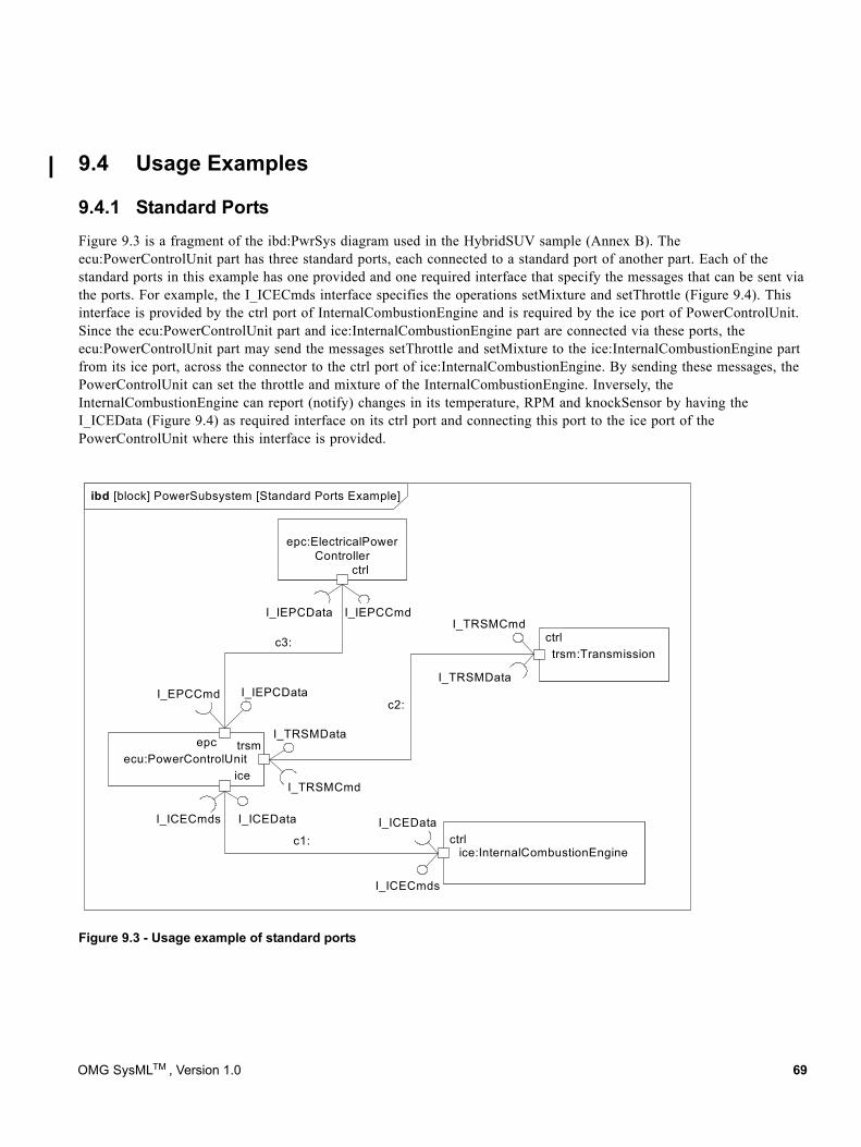
9.4 Usage Examples
9.4.1 Standard PortsFigure 9.3 is a fragment of the ibd:PwrSys diagram used in the HybridSUV sample (Annex B). The ecu:PowerControlUnit part has three standard ports, each connected to a standard port of another part. Each of the standard ports in this example has one provided and one required interface that specify the messages that can be sent via the ports. For example, the I_ICECmds interface specifies the operations setMixture and setThrottle (Figure 9.4). This interface is provided by the ctrl port of InternalCombustionEngine and is required by the ice port of PowerControlUnit. Since the ecu:PowerControlUnit part and ice:InternalCombustionEngine part are connected via these ports, the ecu:PowerControlUnit part may send the messages setThrottle and setMixture to the ice:InternalCombustionEngine part from its ice port, across the connector to the ctrl port of ice:InternalCombustionEngine. By sending these messages, the PowerControlUnit can set the throttle and mixture of the InternalCombustionEngine. Inversely, the InternalCombustionEngine can report (notify) changes in its temperature, RPM and knockSensor by having the I_ICEData (Figure 9.4) as required interface on its ctrl port and connecting this port to the ice port of the PowerControlUnit where this interface is provided.
Figure 9.3 - Usage example of standard ports
ibd [block] PowerSubsystem [Standard Ports Example]
trsm:Transmission
ice:InternalCombustionEngine
ecu:PowerControlUnit
epc:ElectricalPowerController
ice
ctrl
I_ICECmds
I_ICECmds
ctrl
ctrl
I_ICEData I_ICEData
trsmepc
c3:
c2:
c1:
I_IEPCCmdI_IEPCData
I_IEPCDataI_EPCCmd
I_TRSMData
I_TRSMCmd
I_TRSMCmd
I_TRSMData
OMG SysMLTM , Version 1.0 69
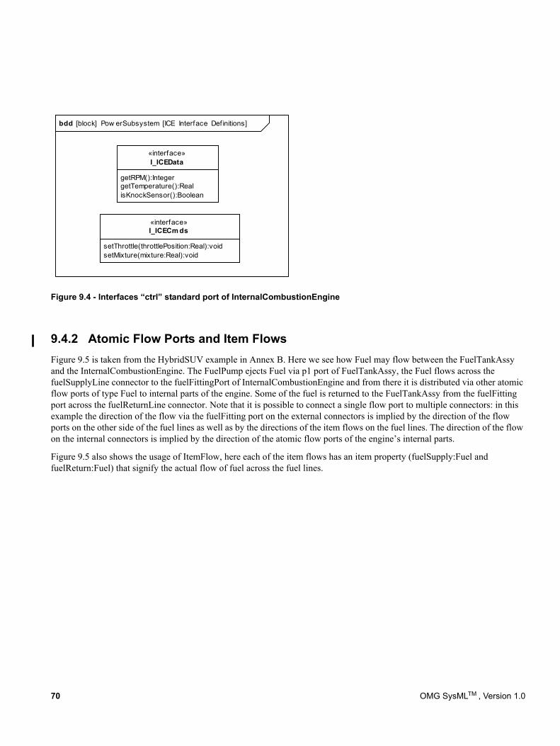
Figure 9.4 - Interfaces “ctrl” standard port of InternalCombustionEngine
9.4.2 Atomic Flow Ports and Item FlowsFigure 9.5 is taken from the HybridSUV example in Annex B. Here we see how Fuel may flow between the FuelTankAssy and the InternalCombustionEngine. The FuelPump ejects Fuel via p1 port of FuelTankAssy, the Fuel flows across the fuelSupplyLine connector to the fuelFittingPort of InternalCombustionEngine and from there it is distributed via other atomic flow ports of type Fuel to internal parts of the engine. Some of the fuel is returned to the FuelTankAssy from the fuelFitting port across the fuelReturnLine connector. Note that it is possible to connect a single flow port to multiple connectors: in this example the direction of the flow via the fuelFitting port on the external connectors is implied by the direction of the flow ports on the other side of the fuel lines as well as by the directions of the item flows on the fuel lines. The direction of the flow on the internal connectors is implied by the direction of the atomic flow ports of the engine’s internal parts.
Figure 9.5 also shows the usage of ItemFlow, here each of the item flows has an item property (fuelSupply:Fuel and fuelReturn:Fuel) that signify the actual flow of fuel across the fuel lines.
getRPM():IntegergetTemperature():RealisKnockSensor():Boolean
«interface»I_ICEData
setThrottle(throttlePosition:Real):voidsetMixture(mixture:Real):void
«interface»I_ICECm ds
bdd [block] Pow erSubsystem [ICE Interface Def initions]
70 OMG SysMLTM , Version 1.0
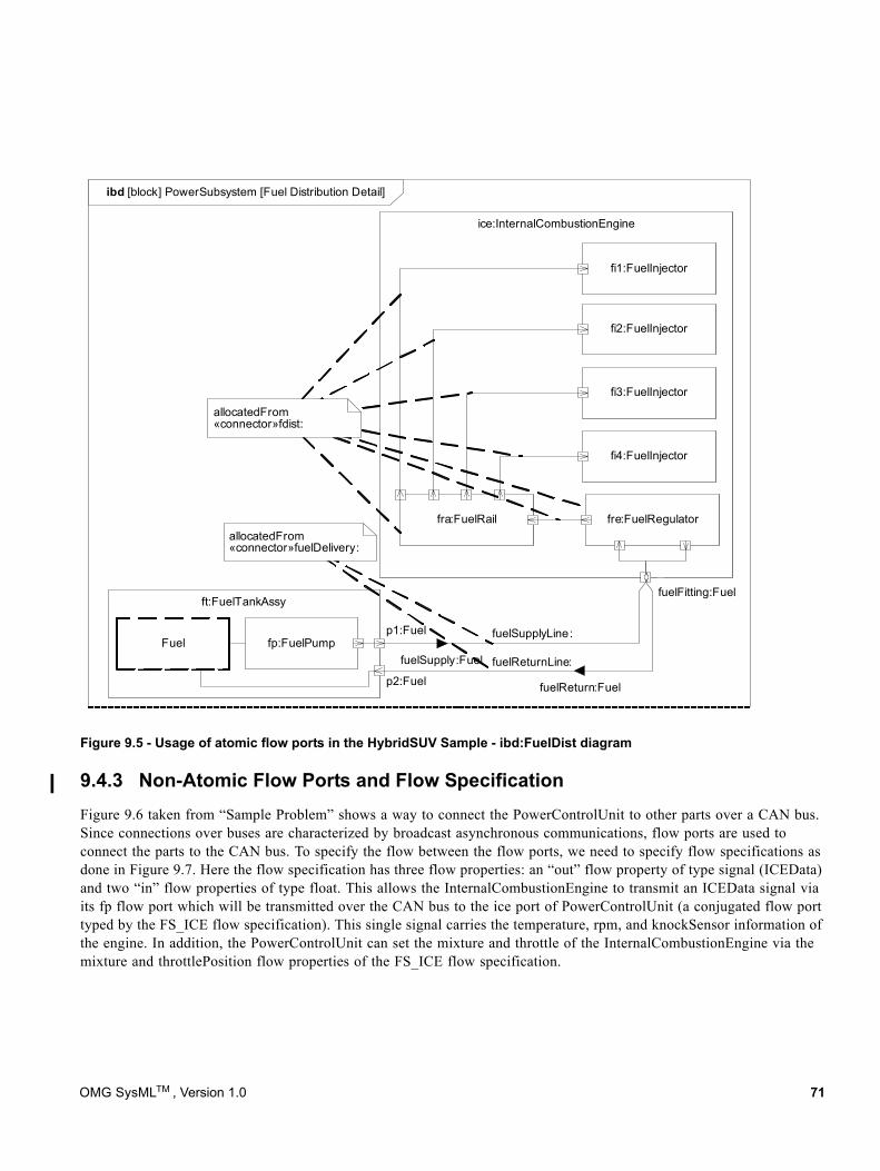
Figure 9.5 - Usage of atomic flow ports in the HybridSUV Sample - ibd:FuelDist diagram
9.4.3 Non-Atomic Flow Ports and Flow SpecificationFigure 9.6 taken from “Sample Problem” shows a way to connect the PowerControlUnit to other parts over a CAN bus. Since connections over buses are characterized by broadcast asynchronous communications, flow ports are used to connect the parts to the CAN bus. To specify the flow between the flow ports, we need to specify flow specifications as done in Figure 9.7. Here the flow specification has three flow properties: an “out” flow property of type signal (ICEData) and two “in” flow properties of type float. This allows the InternalCombustionEngine to transmit an ICEData signal via its fp flow port which will be transmitted over the CAN bus to the ice port of PowerControlUnit (a conjugated flow port typed by the FS_ICE flow specification). This single signal carries the temperature, rpm, and knockSensor information of the engine. In addition, the PowerControlUnit can set the mixture and throttle of the InternalCombustionEngine via the mixture and throttlePosition flow properties of the FS_ICE flow specification.
ibd [block] PowerSubsystem [Fuel Distribution Detail]
ice:InternalCombustionEngine
ft:FuelTankAssy
fuelSupplyLine:
fuelSupply:Fuelfp:FuelPump
fi1:FuelInjector
4
fuelReturn:Fuel
fre:FuelRegulatorfra:FuelRail
p1:Fuel
p2:FuelfuelReturnLine:
fi2:FuelInjector
fi3:FuelInjector
fi4:FuelInjector
allocatedFrom«connector»fdist:
fuelFitting:Fuel
allocatedFrom«connector»fuelDelivery:
<>Fuel
OMG SysMLTM , Version 1.0 71
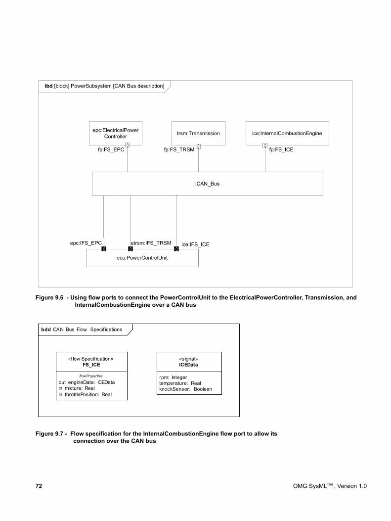
Figure 9.6 - Using flow ports to connect the PowerControlUnit to the ElectricalPowerController, Transmission, and InternalCombustionEngine over a CAN bus
Figure 9.7 - Flow specification for the InternalCombustionEngine flow port to allow its connection over the CAN bus
ibd [block] PowerSubsystem [CAN Bus description]
trsm:Transmission ice:InternalCombustionEngine
ecu:PowerControlUnit
epc:ElectricalPowerController
:CAN_Bus
fp:FS_EPC fp:FS_TRSM fp:FS_ICE
epc:IFS_EPC etrsm:IFS_TRSM ice:IFS_ICE
<> <> <>
<> <> <>
bdd CAN Bus Flow Specif ications
out engineData: ICEDatain mixture: Realin throttlePosition: Real
«f low Specif ication»FS_ICE
flowProperties rpm: Integertemperature: RealknockSensor: Boolean
«signal»ICEData
72 OMG SysMLTM , Version 1.0
10 Constraint Blocks
10.1 OverviewConstraint blocks provide a mechanism for integrating engineering analysis such as performance and reliability models with other SysML models. Constraint blocks can be used to specify a network of constraints that represent mathematical expressions such as {F=m*a} and {a=dv/dt}, which constrain the physical properties of a system. Such constraints can also be used to identify critical performance parameters and their relationships to other parameters, which can be tracked throughout the system life cycle.
A constraint block includes the constraint, such as {F=m*a}, and the parameters of the constraint such as F, m, and a. Constraint blocks define generic forms of constraints that can be used in multiple contexts. For example, a definition for Newton’s Laws may be used to specify these constraints in many different contexts. Reusable constraint definitions may be specified on block definition diagrams and packaged into general-purpose or domain-specific model libraries. Such constraints can be arbitrarily complex mathematical or logical expressions. The constraints can be nested to enable a constraint to be defined in terms of more basic constraints such as primitive mathematical operators.
Parametric diagrams include usages of constraint blocks to constrain the properties of another block. The usage of a constraint binds the parameters of the constraint, such as F, m, and a, to specific properties of a block, such as a mass, that provide values for the parameters. The constrained properties, such as mass or response time, typically have simple value types that may also carry units, dimensions, and probability distributions. A pathname dot notation can be used to refer to nested properties within a block hierarchy. This allows a value property (such as an engine displacement) that may be deeply nested within a containing hierarchy (such as vehicle, power system, engine) to be referenced at the outer containing level (such as vehicle-level equations). The context for the usages of constraint blocks must also be specified in a parametric diagram to maintain the proper namespace for the nested properties.
Time can be modeled as a property that other properties may be dependent on. A time reference can be established by a local or global clock that produces a continuous or discrete time value property. Other values of time can be derived from this clock, by introducing delays and/or skew into the value of time. Discrete values of time as well as calendar time can be derived from this global time property. SysML includes the time model from UML, but other UML specifications offer more specialized descriptions of time that may also apply to specific needs.
A state of the system can be specified in terms of the values of some of its properties. For example, when water temperature is below 0 degrees Celsius, it may change from liquid to solid state. In this example, the change in state results in a different set of constraint equations. This can be accommodated by specifying constraints that are conditioned on the value of the state property.
Parametric diagrams can be used to support trade-off analysis. A constraint block can define an objective function to compare alternative solutions. The objective function can constrain measures of effectiveness or merit and may include a weighting of utility functions associated with various criteria used to evaluate the alternatives. These criteria, for example, could be associated with system performance, cost, or desired physical characteristics. Properties bound to parameters of the objective function may have probability distributions associated with them that are used to compute expected or probabilistic measures of the system. The use of an objective function and measures of effectiveness in parametric diagrams are included in Annex C: Non-normative Extensions.
SysML identifies and names constraint blocks, but does not specify a computer interpretable language for them. The interpretation of a given constraint block (e.g., a mathematical relation between its parameter values) must be provided. An expression may rely on other mathematical description languages both to capture the detailed specification of
OMG SysMLTM , Version 1.0 75
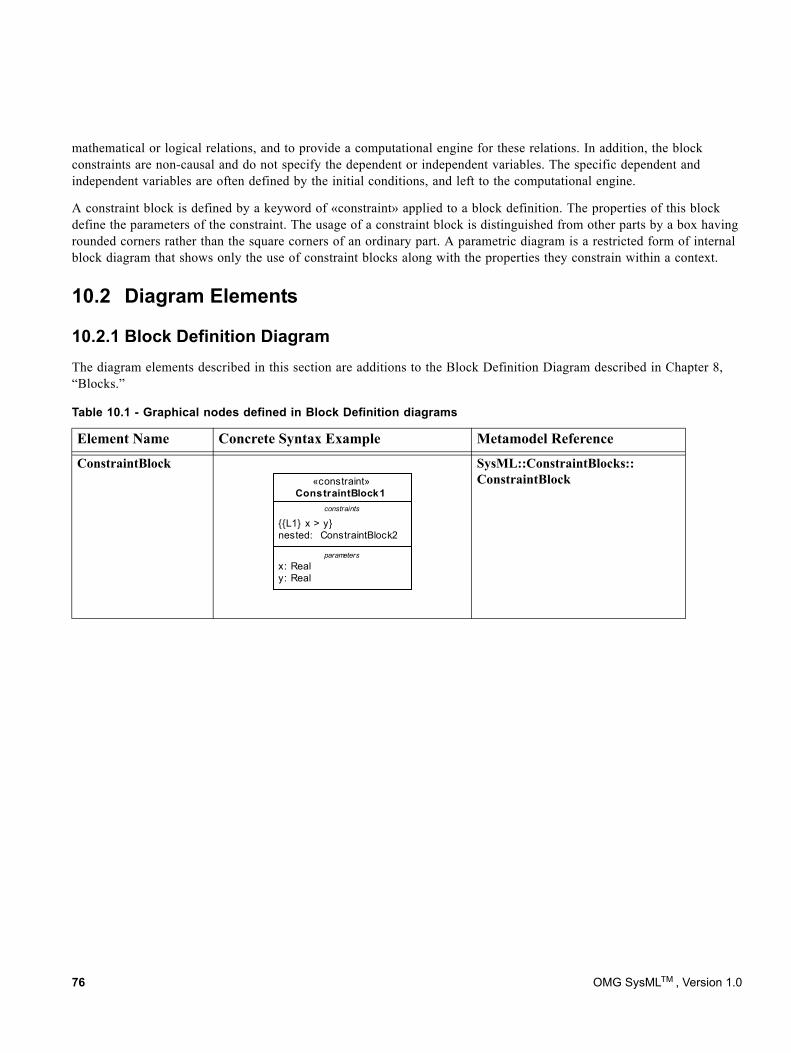
mathematical or logical relations, and to provide a computational engine for these relations. In addition, the block constraints are non-causal and do not specify the dependent or independent variables. The specific dependent and independent variables are often defined by the initial conditions, and left to the computational engine.
A constraint block is defined by a keyword of «constraint» applied to a block definition. The properties of this block define the parameters of the constraint. The usage of a constraint block is distinguished from other parts by a box having rounded corners rather than the square corners of an ordinary part. A parametric diagram is a restricted form of internal block diagram that shows only the use of constraint blocks along with the properties they constrain within a context.
10.2 Diagram Elements
10.2.1 Block Definition DiagramThe diagram elements described in this section are additions to the Block Definition Diagram described in Chapter 8, “Blocks.”
Table 10.1 - Graphical nodes defined in Block Definition diagrams
Element Name Concrete Syntax Example Metamodel Reference
ConstraintBlock SysML::ConstraintBlocks:: ConstraintBlock
x: Realy: Real
{{L1} x > y}nested: ConstraintBlock2
«constraint»ConstraintBlock1
constraints
parameters
76 OMG SysMLTM , Version 1.0

10.2.2 Parametric DiagramThe diagram elements described in this section are additions to the Internal Block Diagram described in Chapter 8, “Blocks.” The Parametric Diagram includes all of the notations of an Internal Block Diagram, subject only to the restrictions described in Section 10.3.1.2.
10.3 UML Extensions
10.3.1 Diagram Extensions
10.3.1.1 Block Definition Diagram
Constraint block definition
The «constraint» keyword on a block definition states that the block is a constraint block. An expression that specifies the constraint may appear in the constraints compartment of the block definition, using either formal statements in some language, or informal statements using text. This expression can include a formal reference to a language in braces as indicated in Table 10.1. Parameters of the constraint may be shown in a compartment with the predefined compartment label “parameters.”
Table 10.2 - Graphical nodes defined in Parametric diagrams.
Element Name Concrete Syntax Example Metamodel Reference
ParametricDiagram SysML::Constraint-Blocks::ConstraintBlock SysML::Blocks::Block
ConstraintProperty SysML::ConstraintBlocks:: ConstraintProperty
C1: Constraint1
x:
y:
length: Real
width: Real
par Block1
C1: Constraint1
x: Real
y: Real
x: Real
y: Real
«constraint»C1: Constraint1
OMG SysMLTM , Version 1.0 77
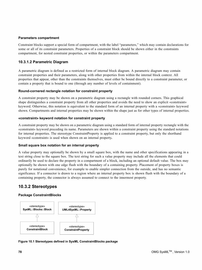
Parameters compartment
Constraint blocks support a special form of compartment, with the label “parameters,” which may contain declarations for some or all of its constraint parameters. Properties of a constraint block should be shown either in the constraints compartment, for nested constraint properties, or within the parameters compartment.
10.3.1.2 Parametric Diagram
A parametric diagram is defined as a restricted form of internal block diagram. A parametric diagram may contain constraint properties and their parameters, along with other properties from within the internal block context. All properties that appear, other than the constraints themselves, must either be bound directly to a constraint parameter, or contain a property that is bound to one (through any number of levels of containment).
Round-cornered rectangle notation for constraint property
A constraint property may be shown on a parametric diagram using a rectangle with rounded corners. This graphical shape distinguishes a constraint property from all other properties and avoids the need to show an explicit «constraint» keyword. Otherwise, this notation is equivalent to the standard form of an internal property with a «constraint» keyword shown. Compartments and internal properties may be shown within the shape just as for other types of internal properties.
«constraint» keyword notation for constraint property
A constraint property may be shown on a parametric diagram using a standard form of internal property rectangle with the «constraint» keyword preceding its name. Parameters are shown within a constraint property using the standard notations for internal properties. The stereotype ConstraintProperty is applied to a constraint property, but only the shorthand keyword «constraint» is used when shown on an internal property.
Small square box notation for an internal property
A value property may optionally be shown by a small square box, with the name and other specifications appearing in a text string close to the square box. The text string for such a value property may include all the elements that could ordinarily be used to declare the property in a compartment of a block, including an optional default value. The box may optionally be shown with one edge flush with the boundary of a containing property. Placement of property boxes is purely for notational convenience, for example to enable simpler connection from the outside, and has no semantic significance. If a connector is drawn to a region where an internal property box is shown flush with the boundary of a containing property, the connector is always assumed to connect to the innermost property.
10.3.2 Stereotypes
Package ConstraintBlocks
«stereotype»SysML::Blocks::Block
«stereotype»ConstraintBlock
«stereotype»UML4SysML::Property
«stereotype»ConstraintProperty
Figure 10.1 Stereotypes defined in SysML ConstraintBlocks package
78 OMG SysMLTM , Version 1.0
10.3.2.1 ConstraintBlock
Description
A constraint block is a block that packages the statement of a constraint so it may be applied in a reusable way to constrain properties of other blocks. A constraint block typically defines one or more constraint parameters, which are bound to properties of other blocks in a surrounding context where the constraint is used. Binding connectors, as defined in Chapter 8: Blocks, are used to bind each parameter of the constraint block to a property in the surrounding context. All properties of a constraint block are constraint parameters, with the exception of constraint properties that hold internally nested usages of other constraint blocks.
Constraints[1] A constraint block may not own any structural or behavioral elements beyond the properties that define its constraint
parameters, constraint properties that hold internal usages of constraint blocks, binding connectors between its internally nested constraint parameters, constraint expressions that define an interpretation for the constraint block, and general-purpose model management and crosscutting elements.
[2] Any classifier which specializes a ConstraintBlock must also have the ConstraintBlock stereotype applied.
10.3.2.2 ConstraintProperty
Description
A constraint property is a property of any block that is typed by a constraint block. It holds a localized usage of the constraint block. Binding connectors may be used to bind the parameters of this constraint block to other properties of the block that contains the usage.
Constraints[1] A property to which the ConstraintProperty stereotype is applied must be owned by a SysML Block.
[2] The ConstraintProperty stereotype must be applied to any property of a SysML Block that is typed by a ConstraintBlock.
10.4 Usage Examples
10.4.1 Definition of Constraint Blocks on a Block Definition DiagramConstraint blocks can only be defined on a block definition diagram or a package diagram, where they must have the «constraint» keyword shown. The strings in braces in the compartment labeled “constraints” are ordinary UML constraints, using a special compartment to hold the constraint. This is shown in Figure 10.2. These particular constraints are specified only in an informal language, but a more formal language such as OCL or MathML could also be used. The compartment labeled “parameters” shows the parameters of this constraint, which are bound on the parametric diagram.
OMG SysMLTM , Version 1.0 79
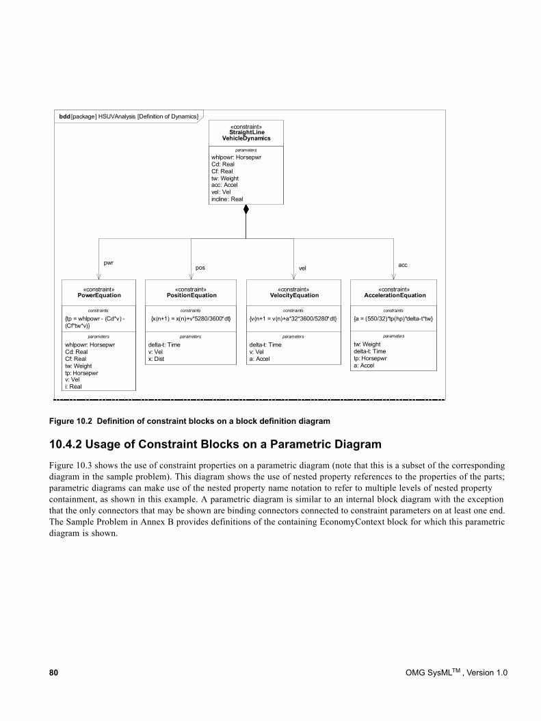
Figure 10.2 Definition of constraint blocks on a block definition diagram
10.4.2 Usage of Constraint Blocks on a Parametric DiagramFigure 10.3 shows the use of constraint properties on a parametric diagram (note that this is a subset of the corresponding diagram in the sample problem). This diagram shows the use of nested property references to the properties of the parts; parametric diagrams can make use of the nested property name notation to refer to multiple levels of nested property containment, as shown in this example. A parametric diagram is similar to an internal block diagram with the exception that the only connectors that may be shown are binding connectors connected to constraint parameters on at least one end. The Sample Problem in Annex B provides definitions of the containing EconomyContext block for which this parametric diagram is shown.
bdd [package] HSUVAnalysis [Definition of Dynamics]
accvelpwr
pos
tw: Weightdelta-t: Timetp: Horsepwra: Accel
{a = (550/32)*tp(hp)*delta-t*tw}
«constraint»AccelerationEquation
parameters
constraints
delta-t: Timev: Vela: Accel
{v(n+1 = v(n)+a*32*3600/5280*dt}
«constraint»VelocityEquation
parameters
constraints
delta-t: Timev: Velx: Dist
{x(n+1) = x(n)+v*5280/3600*dt}
«constraint»PositionEquation
parameters
constraints
whlpowr: HorsepwrCd: RealCf: Realtw: Weighttp: Horsepwrv: Veli: Real
{tp = whlpowr - (Cd*v) -(Cf*tw*v)}
«constraint»PowerEquation
parameters
constraints
whlpowr: HorsepwrCd: RealCf: Realtw: Weightacc: Accelvel: Velincline: Real
«constraint»StraightLine
VehicleDynamics
parameters
80 OMG SysMLTM , Version 1.0
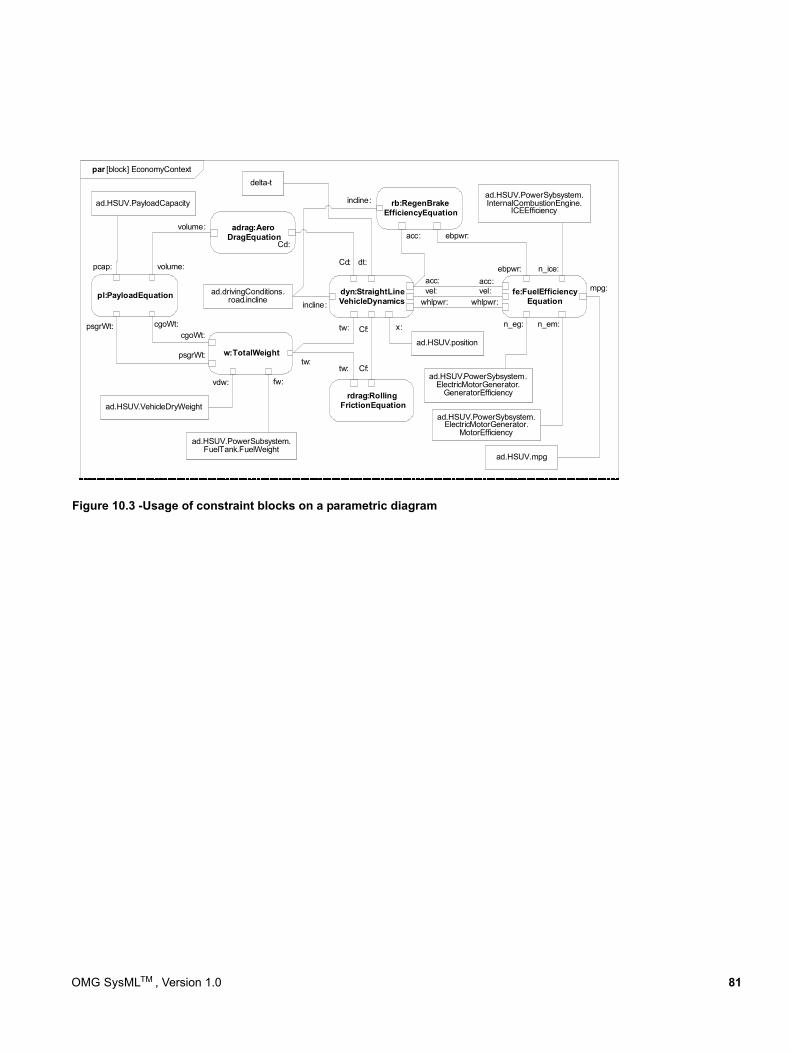
Figure 10.3 -Usage of constraint blocks on a parametric diagram
par [block] EconomyContext
dyn:StraightLineVehicleDynamics
rdrag:RollingFrictionEquation
adrag:AeroDragEquation
w:TotalWeight
pl:PayloadEquation
cgoWt:psgrWt:
psgrWt:
volume:
volume:
vdw: fw:
ad.HSUV.PowerSubsystem.FuelTank.FuelWeight
Cd:
Cd:
tw:
tw:
tw:
Cf:
Cf:
fe:FuelEfficiencyEquationwhlpwr:
acc:acc:vel: mpg:
incline:
rb:RegenBrakeEfficiencyEquation
vel:
incline:
ebpwr:
ebpwr:
n_em:
acc:
n_ice:
n_eg:
ad.HSUV.PayloadCapacity
pcap:
cgoWt:
whlpwr:
ad.HSUV.VehicleDryWeight
ad.HSUV.PowerSybsystem.ElectricMotorGenerator.
GeneratorEfficiency
ad.HSUV.PowerSybsystem.ElectricMotorGenerator.
MotorEfficiency
ad.HSUV.PowerSybsystem.InternalCombustionEngine.
ICEEfficiency
ad.drivingConditions.road.incline
ad.HSUV.position
x:
ad.HSUV.mpg
dt:
delta-t
OMG SysMLTM , Version 1.0 81

82 OMG SysMLTM , Version 1.0
Part III - Behavioral Constructs
This Part specifies the dynamic, behavioral constructs used in SysML behavioral diagrams, including the activity diagram, sequence diagram, state machine diagram, and use case diagram. This part includes the following chapters:
Chapter 11 - Activities - defines the extensions to UML 2 activities, which represent the basic unit of behavior that is used in activity, sequence, and state machine diagrams. The activity diagram is used to describe the flow of control and flow of inputs and outputs among actions.
Chapter 12 - Interactions - defines the constructs for describing message based behavior used in sequence diagrams.
Chapter 13 - State Machines - describes the constructs used to specify state based behavior in terms of system states and their transitions.
Chapter 14 - Use Cases - describes behavior in terms of the high level functionality and uses of a system, that are further specified in the other behavioral diagrams referred to above.
OMG SysMLTM , Version 1.0 83

84 OMG SysMLTM , Version 1.0
11 Activities
11.1 OverviewActivity modeling emphasizes the inputs, outputs, sequences, and conditions for coordinating other behaviors. It provides a flexible link to blocks owning those behaviors. The following is a summary of the SysML extensions to UML 2.1 Activity diagrams. For additional information, see extensions for Enhanced Functional Flow Block Diagrams in Annex C, “Non-normative Extensions,” Section C.1, “Activity Diagram Extensions.”
11.1.1 Control as DataSysML extends control in activity diagrams as follows.
• In UML 2.1 Activities, control can only enable actions to start. SysML extends control to support disabling of actions that are already executing. This is accomplished by providing a model library with a type for control values that are treated like data (see ControlValue in Figure 11.9).
• A control value is an input or output of a control operator, which is how control acts as data. A control operator can represent a complex logical operation that transforms its inputs to produce an output that controls other actions (see ControlOperator in Figure 11.8).
11.1.2 Continuous SystemsSysML provides extensions that might be very loosely grouped under the term “continuous,” but are generally applicable to any sort of distributed flow of information and physical items through a system. These are:
• Restrictions on the rate at which entities flow along edges in an activity, or in and out of parameters of a behavior (see Rate in Figure 11.8). This includes both discrete and continuous flows, either of material, energy, or information. Discrete and continuous flows are unified under rate of flow, as is traditionally done in mathematical models of continuous change, where the discrete increment of time approaches zero.
• Extension of object nodes, including pins, with the option for newly arriving values to replace values that are already in the object nodes (see Overwrite in Figure 11.8). SysML also extends object nodes with the option to discard values if they do not immediately flow downstream (see NoBuffer in Figure 11.8). These two extensions are useful for ensuring that the most recent information is available to actions by indicating when old values should not be kept in object nodes, and for preventing fast or continuously flowing values from collecting in an object node, as well as modeling transient values, such as electrical signals.
11.1.3 ProbabilitySysML introduces probability into activities as follows (see Probability in Figure 11.8):
• Extension of edges with probabilities for the likelihood that a value leaving the decision node or object node will traverse an edge.
• Extension of output parameter sets with probabilities for the likelihood that values will be output on a parameter set.
OMG SysMLTM , Version 1.0 85
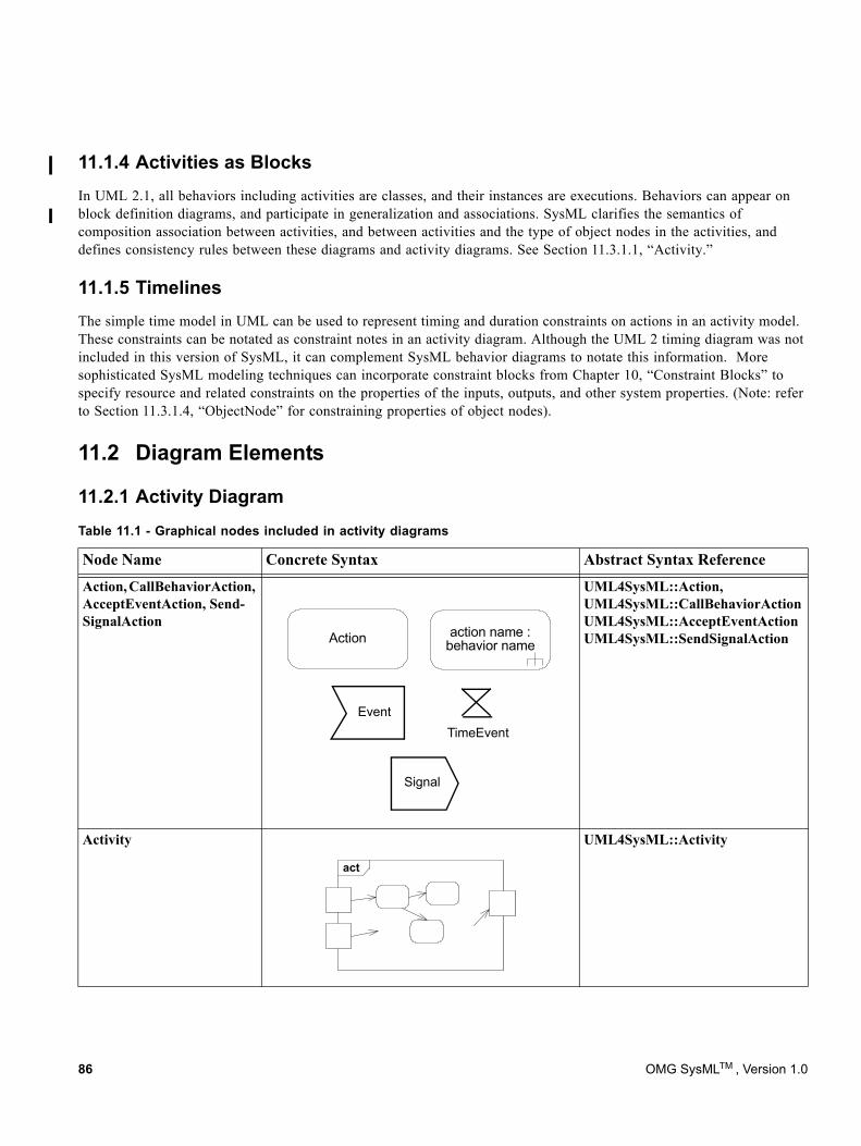
11.1.4 Activities as BlocksIn UML 2.1, all behaviors including activities are classes, and their instances are executions. Behaviors can appear on block definition diagrams, and participate in generalization and associations. SysML clarifies the semantics of composition association between activities, and between activities and the type of object nodes in the activities, and defines consistency rules between these diagrams and activity diagrams. See Section 11.3.1.1, “Activity.”
11.1.5 TimelinesThe simple time model in UML can be used to represent timing and duration constraints on actions in an activity model. These constraints can be notated as constraint notes in an activity diagram. Although the UML 2 timing diagram was not included in this version of SysML, it can complement SysML behavior diagrams to notate this information. More sophisticated SysML modeling techniques can incorporate constraint blocks from Chapter 10, “Constraint Blocks” to specify resource and related constraints on the properties of the inputs, outputs, and other system properties. (Note: refer to Section 11.3.1.4, “ObjectNode” for constraining properties of object nodes).
11.2 Diagram Elements
11.2.1 Activity DiagramTable 11.1 - Graphical nodes included in activity diagrams
Node Name Concrete Syntax Abstract Syntax Reference
Action, CallBehaviorAction, AcceptEventAction, Send-SignalAction
Action action name : behavior name
Event
Signal
TimeEvent
UML4SysML::Action, UML4SysML::CallBehaviorActionUML4SysML::AcceptEventAction UML4SysML::SendSignalAction
Activity
act
UML4SysML::Activity
86 OMG SysMLTM , Version 1.0
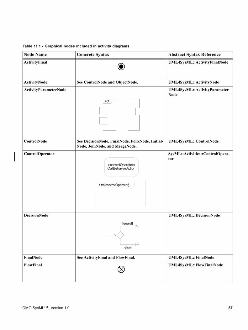
ActivityFinal UML4SysML::ActivityFinalNode
ActivityNode See ControlNode and ObjectNode. UML4SysML::ActivityNode
ActivityParameterNode
act
UML4SysML::ActivityParameter-Node
ControlNode See DecisionNode, FinalNode, ForkNode, Initial-Node, JoinNode, and MergeNode.
UML4SysML::ControlNode
ControlOperator
act [controlOperator]
«controlOperator»CallBehaviorAction
SysML::Activities::ControlOpera-tor
DecisionNode
[guard]
[else]
UML4SysML::DecisionNode
FinalNode See ActivityFinal and FlowFinal. UML4SysML::FinalNode
FlowFinal UML4SysML::FlowFinalNode
Table 11.1 - Graphical nodes included in activity diagrams
Node Name Concrete Syntax Abstract Syntax Reference
OMG SysMLTM , Version 1.0 87
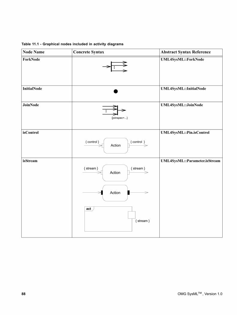
ForkNode
...
UML4SysML::ForkNode
InitialNode UML4SysML::InitialNode
JoinNode...
{joinspec=...}
UML4SysML::JoinNode
isControl
{ control }Action
{ control }
UML4SysML::Pin.isControl
isStream
{ stream }{ stream }Action
{ stream }
act
Action
UML4SysML::Parameter.isStream
Table 11.1 - Graphical nodes included in activity diagrams
Node Name Concrete Syntax Abstract Syntax Reference
88 OMG SysMLTM , Version 1.0
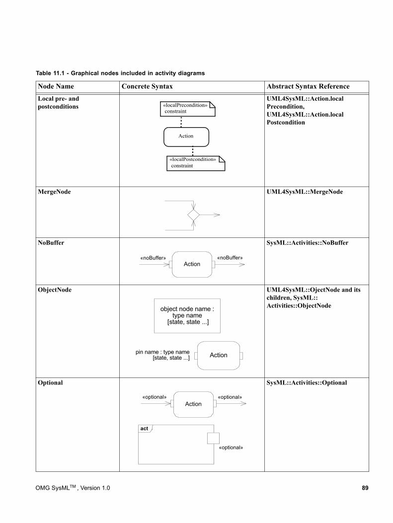
Local pre- and postconditions «localPrecondition»
constraint
Action
«localPostcondition»constraint
UML4SysML::Action.local Precondition, UML4SysML::Action.local Postcondition
MergeNode UML4SysML::MergeNode
NoBuffer
«noBuffer»Action
«noBuffer»
SysML::Activities::NoBuffer
ObjectNode
object node name : type name
[state, state ...]
Actionpin name : type name [state, state ...]
UML4SysML::OjectNode and its children, SysML:: Activities::ObjectNode
Optional
«optional» «optional»Action
«optional»
act
SysML::Activities::Optional
Table 11.1 - Graphical nodes included in activity diagrams
Node Name Concrete Syntax Abstract Syntax Reference
OMG SysMLTM , Version 1.0 89
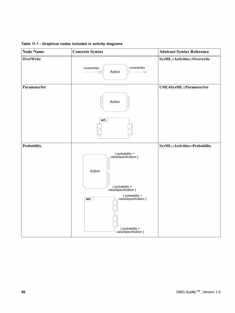
OverWrite
«overwrite»Action
«overwrite»
SysML::Activities::Overwrite
ParameterSet
Action
act
UML4SysML::ParameterSet
Probability
Action
{ probability =valueSpecification }
{ probability =valueSpecification }
act{ probability =
valueSpecification }
{ probability =valueSpecification }
SysML::Activities::Probability
Table 11.1 - Graphical nodes included in activity diagrams
Node Name Concrete Syntax Abstract Syntax Reference
90 OMG SysMLTM , Version 1.0
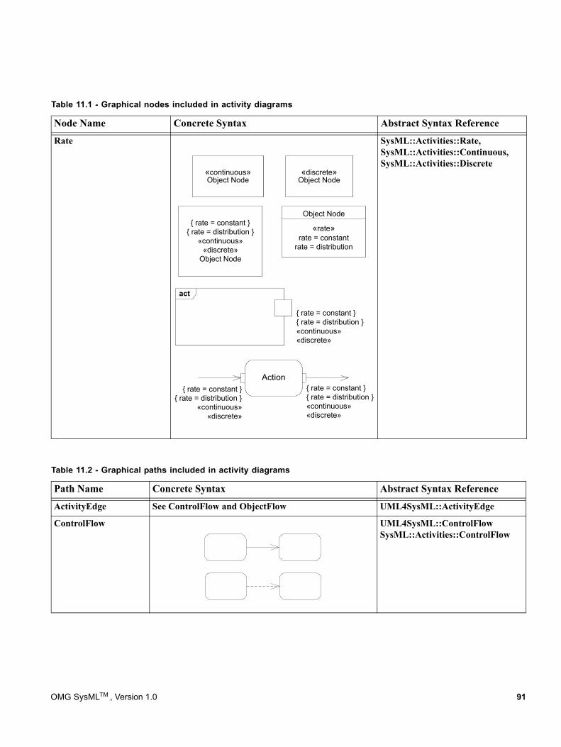
Rate
{ rate = constant }{ rate = distribution }«continuous»«discrete»
«discrete»Object Node
«continuous»Object Node
{ rate = constant }{ rate = distribution }
«continuous»«discrete»
Object Node
Object Node
«rate»rate = constant
rate = distribution
{ rate = constant }{ rate = distribution }
«continuous»«discrete»
Action{ rate = constant }{ rate = distribution }«continuous»«discrete»
act
SysML::Activities::Rate, SysML::Activities::Continuous, SysML::Activities::Discrete
Table 11.2 - Graphical paths included in activity diagrams
Path Name Concrete Syntax Abstract Syntax Reference
ActivityEdge See ControlFlow and ObjectFlow UML4SysML::ActivityEdge
ControlFlow UML4SysML::ControlFlowSysML::Activities::ControlFlow
Table 11.1 - Graphical nodes included in activity diagrams
Node Name Concrete Syntax Abstract Syntax Reference
OMG SysMLTM , Version 1.0 91
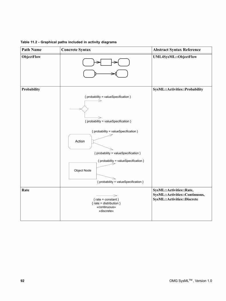
ObjectFlow UML4SysML::ObjectFlow
Probability
{ probability = valueSpecification }
{ probability = valueSpecification }
Action
{ probability = valueSpecification }
{ probability = valueSpecification }
Object Node
{ probability = valueSpecification }
{ probability = valueSpecification }
SysML::Activities::Probability
Rate
{ rate = constant }{ rate = distribution }
«continuous»«discrete»
SysML::Activities::Rate, SysML::Activities::Continuous, SysML::Activities::Discrete
Table 11.2 - Graphical paths included in activity diagrams
Path Name Concrete Syntax Abstract Syntax Reference
92 OMG SysMLTM , Version 1.0
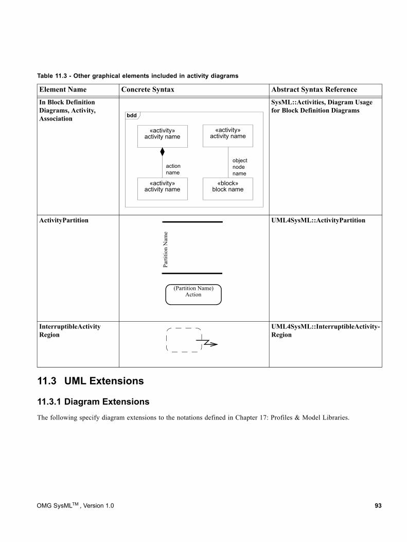
In Block Definition Diagrams, Activity, Association
«activity»activity name
actionname
«activity»activity name
«activity»activity name
objectnodename
«block»block name
bdd
SysML::Activities, Diagram Usage for Block Definition Diagrams
ActivityPartition
Parti
tion
Nam
e
Action(Partition Name)
UML4SysML::ActivityPartition
InterruptibleActivity Region
UML4SysML::InterruptibleActivity-Region
11.3 UML Extensions
11.3.1 Diagram ExtensionsThe following specify diagram extensions to the notations defined in Chapter 17: Profiles & Model Libraries.
Table 11.3 - Other graphical elements included in activity diagrams
Element Name Concrete Syntax Abstract Syntax Reference
OMG SysMLTM , Version 1.0 93
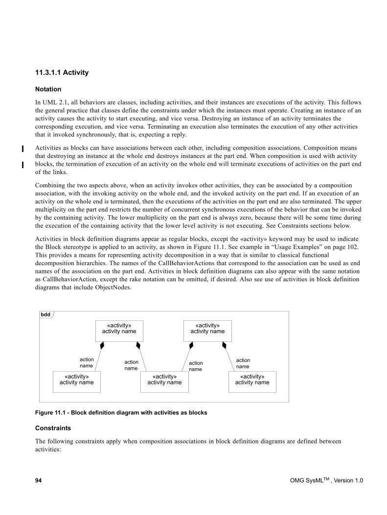
11.3.1.1 Activity
Notation
In UML 2.1, all behaviors are classes, including activities, and their instances are executions of the activity. This follows the general practice that classes define the constraints under which the instances must operate. Creating an instance of an activity causes the activity to start executing, and vice versa. Destroying an instance of an activity terminates the corresponding execution, and vice versa. Terminating an execution also terminates the execution of any other activities that it invoked synchronously, that is, expecting a reply.
Activities as blocks can have associations between each other, including composition associations. Composition means that destroying an instance at the whole end destroys instances at the part end. When composition is used with activity blocks, the termination of execution of an activity on the whole end will terminate executions of activities on the part end of the links.
Combining the two aspects above, when an activity invokes other activities, they can be associated by a composition association, with the invoking activity on the whole end, and the invoked activity on the part end. If an execution of an activity on the whole end is terminated, then the executions of the activities on the part end are also terminated. The upper multiplicity on the part end restricts the number of concurrent synchronous executions of the behavior that can be invoked by the containing activity. The lower multiplicity on the part end is always zero, because there will be some time during the execution of the containing activity that the lower level activity is not executing. See Constraints sections below.
Activities in block definition diagrams appear as regular blocks, except the «activity» keyword may be used to indicate the Block stereotype is applied to an activity, as shown in Figure 11.1. See example in “Usage Examples” on page 102. This provides a means for representing activity decomposition in a way that is similar to classical functional decomposition hierarchies. The names of the CallBehaviorActions that correspond to the association can be used as end names of the association on the part end. Activities in block definition diagrams can also appear with the same notation as CallBehaviorAction, except the rake notation can be omitted, if desired. Also see use of activities in block definition diagrams that include ObjectNodes.
Constraints
The following constraints apply when composition associations in block definition diagrams are defined between activities:
Figure 11.1 - Block definition diagram with activities as blocks
actionname
actionname
actionname
«activity»activity name
«activity»activity name
«activity»activity name
«activity»activity name
actionname
«activity»activity name
bdd
94 OMG SysMLTM , Version 1.0
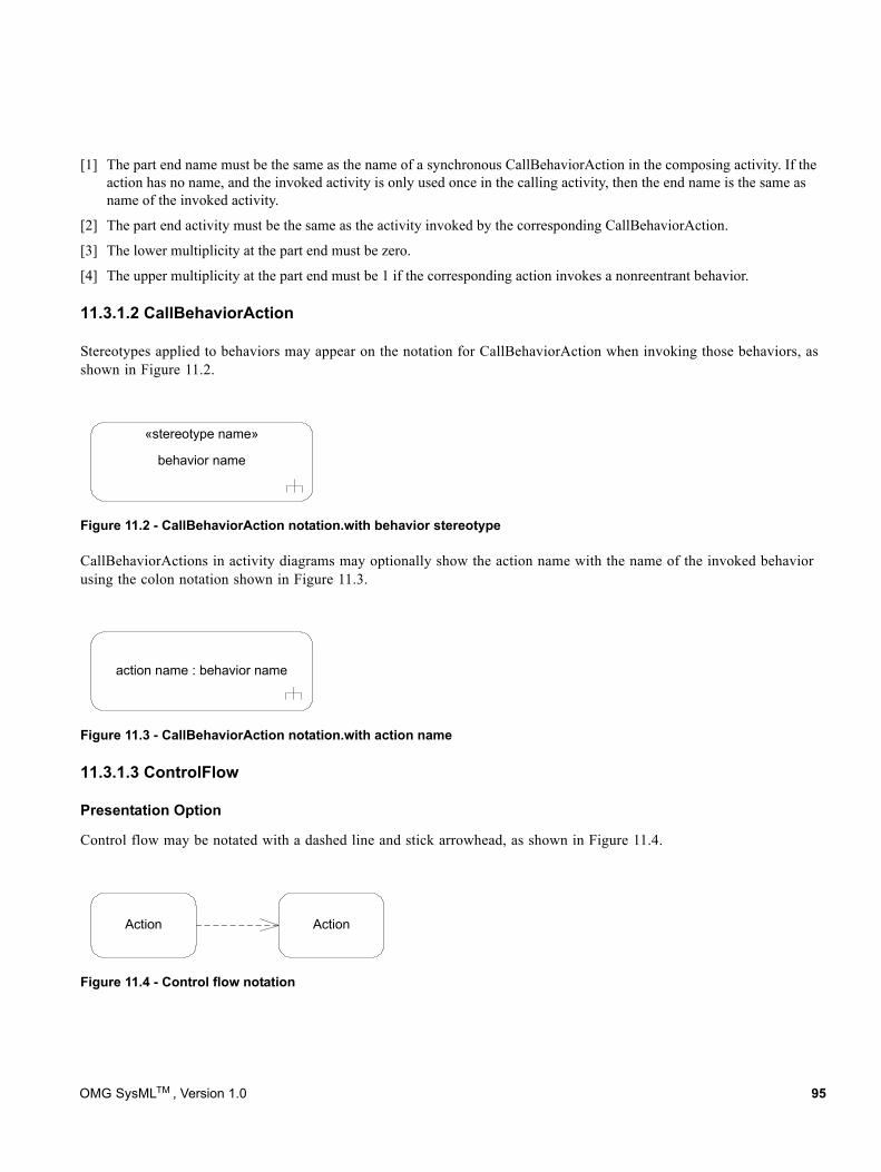
[1] The part end name must be the same as the name of a synchronous CallBehaviorAction in the composing activity. If the action has no name, and the invoked activity is only used once in the calling activity, then the end name is the same as name of the invoked activity.
[2] The part end activity must be the same as the activity invoked by the corresponding CallBehaviorAction.
[3] The lower multiplicity at the part end must be zero.
[4] The upper multiplicity at the part end must be 1 if the corresponding action invokes a nonreentrant behavior.
11.3.1.2 CallBehaviorAction
Stereotypes applied to behaviors may appear on the notation for CallBehaviorAction when invoking those behaviors, as shown in Figure 11.2.
CallBehaviorActions in activity diagrams may optionally show the action name with the name of the invoked behavior using the colon notation shown in Figure 11.3.
11.3.1.3 ControlFlow
Presentation Option
Control flow may be notated with a dashed line and stick arrowhead, as shown in Figure 11.4.
Figure 11.2 - CallBehaviorAction notation.with behavior stereotype
Figure 11.3 - CallBehaviorAction notation.with action name
Figure 11.4 - Control flow notation
«stereotype name»
behavior name
action name : behavior name
Action Action
OMG SysMLTM , Version 1.0 95
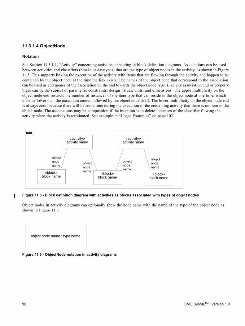
11.3.1.4 ObjectNode
Notation
See Section 11.3.1.1, “Activity” concerning activities appearing in block definition diagrams. Associations can be used between activities and classifiers (blocks or datatypes) that are the type of object nodes in the activity, as shown in Figure 11.5. This supports linking the execution of the activity with items that are flowing through the activity and happen to be contained by the object node at the time the link exists. The names of the object node that correspond to the association can be used as end names of the association on the end towards the object node type. Like any association end or property these can be the subject of parametric constraints, design values, units, and dimensions. The upper multiplicity on the object node end restricts the number of instances of the item type that can reside in the object node at one time, which must be lower than the maximum amount allowed by the object node itself. The lower multiplicity on the object node end is always zero, because there will be some time during the execution of the containing activity that there is no item in the object node. The associations may be composition if the intention is to delete instances of the classifier flowing the activity when the activity is terminated. See example in “Usage Examples” on page 102.
Object nodes in activity diagrams can optionally show the node name with the name of the type of the object node as shown in Figure 11.6.
Figure 11.5 - Block definition diagram with activities as blocks associated with types of object nodes
Figure 11.6 - ObjectNode notation in activity diagrams
objectnodename object
nodename
objectnodename
«activity»activity name
«activity»activity name
objectnodename
«block»block name
«block»block name
«block»block name
bdd
object node name : type name
96 OMG SysMLTM , Version 1.0
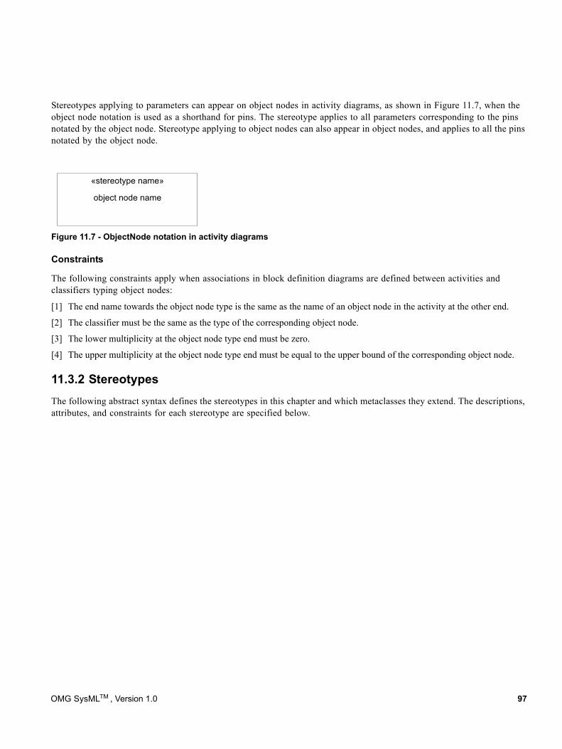
Stereotypes applying to parameters can appear on object nodes in activity diagrams, as shown in Figure 11.7, when the object node notation is used as a shorthand for pins. The stereotype applies to all parameters corresponding to the pins notated by the object node. Stereotype applying to object nodes can also appear in object nodes, and applies to all the pins notated by the object node.
Constraints
The following constraints apply when associations in block definition diagrams are defined between activities and classifiers typing object nodes:
[1] The end name towards the object node type is the same as the name of an object node in the activity at the other end.
[2] The classifier must be the same as the type of the corresponding object node.
[3] The lower multiplicity at the object node type end must be zero.
[4] The upper multiplicity at the object node type end must be equal to the upper bound of the corresponding object node.
11.3.2 StereotypesThe following abstract syntax defines the stereotypes in this chapter and which metaclasses they extend. The descriptions, attributes, and constraints for each stereotype are specified below.
Figure 11.7 - ObjectNode notation in activity diagrams
«stereotype name»
object node name
OMG SysMLTM , Version 1.0 97
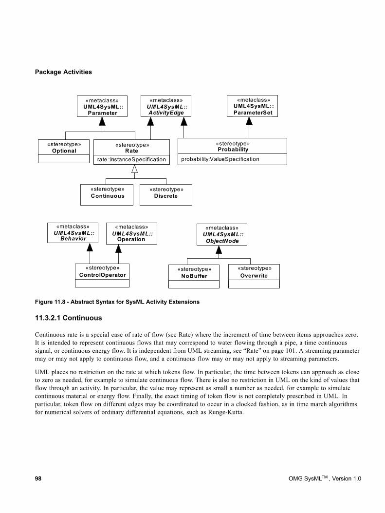
Package Activities
Figure 11.8 - Abstract Syntax for SysML Activity Extensions
11.3.2.1 Continuous
Continuous rate is a special case of rate of flow (see Rate) where the increment of time between items approaches zero. It is intended to represent continuous flows that may correspond to water flowing through a pipe, a time continuous signal, or continuous energy flow. It is independent from UML streaming, see “Rate” on page 101. A streaming parameter may or may not apply to continuous flow, and a continuous flow may or may not apply to streaming parameters.
UML places no restriction on the rate at which tokens flow. In particular, the time between tokens can approach as close to zero as needed, for example to simulate continuous flow. There is also no restriction in UML on the kind of values that flow through an activity. In particular, the value may represent as small a number as needed, for example to simulate continuous material or energy flow. Finally, the exact timing of token flow is not completely prescribed in UML. In particular, token flow on different edges may be coordinated to occur in a clocked fashion, as in time march algorithms for numerical solvers of ordinary differential equations, such as Runge-Kutta.
ControlOperator Overwrite
ActivityEdge
«metaclass»«metaclass»
Optional«stereotype»
NoBuffer
ParameterSet
«metaclass»
Probability
probability : ValueSpecificationRate
rate : InstanceSpecification
DiscreteContinuous
UML4SysML:: UML4SysML::
UML4SysML:: UML4SysML::UML4SysML::
«stereotype» «stereotype»
«stereotype» «stereotype»
«stereotype» «stereotype» «stereotype»
ParameterUML4SysML::
«metaclass» «metaclass» «metaclass»
Behavior ObjectNodeOperation
98 OMG SysMLTM , Version 1.0
11.3.2.2 ControlOperator
Description
A control operator is a behavior that is intended to represent an arbitrarily complex logical operator that can be used to enable and disable other actions. When the «controlOperator» stereotype is applied to behaviors, the behavior takes control values as inputs or provides them as outputs, that is, it treats control as data (see “ControlValue” on page 101). When the «controlOperator» stereotype is not applied, the behavior may not have a parameter typed by ControlValue. The «controlOperator» stereotype also applies to operations with the same semantics.
The control value inputs do not enable or disable the control operator execution based on their value, they only enable based on their presence as data. Pins for control parameters are regular pins, not UML control pins. This is so the control value can be passed into or out of the action and the invoked behavior, rather than control the starting of the action, or indicating the ending of it.
Constraints[1] When the «controlOperator» stereotype is applied, the behavior or operation must have at least one parameter typed by
ControlValue. If the stereotype is not applied, the behavior or operation may not have any parameter typed by ControlValue.
[2] A behavior must have the «controlOperator» stereotype applied if it is a method of an operation that has the «controlOperator» stereotype applied.
11.3.2.3 Discrete
Description
Discrete rate is a special case of rate of flow (see Rate) where the increment of time between items is non-zero. Examples include the production of assemblies in a factory and signals set at periodic time intervals.
Constraints[1] The «discrete» and «continuous» stereotypes cannot be applied to the same element at the same time.
11.3.2.4 NoBuffer
Description
When the «nobuffer» stereotype is applied to object nodes, tokens arriving at the node are discarded if they are refused by outgoing edges, or refused by actions for object nodes that are input pins. This is typically used with fast or continuously flowing data values, to prevent buffer overrun, or to model transient values, such as electrical signals. For object nodes that are the target of continuous flows, «nobuffer» and «overwrite» have the same effect. The stereotype does not override UML token offering semantics; it just indicates what happens to the token when it is accepted. When the stereotype is not applied, the semantics are as in UML, specifically, tokens arriving at an object node that are refused by outgoing edges, or action for input pins, are held until they can leave the object node.
Constraints[1] The «nobuffer» and «overwrite» stereotypes cannot be applied to the same element at the same time.
OMG SysMLTM , Version 1.0 99
11.3.2.5 Overwrite
Description
When the «overwrite» stereotype is applied to object nodes, a token arriving at a full object node replaces the ones already there (a full object node has as many tokens as allowed by its upper bound). This is typically used on an input pin with an upper bound of 1 to ensure that stale data is overridden at an input pin. For upper bounds greater than one, the token replaced is the one that would be the last to be selected according to the ordering kind for the node. For FIFO ordering, this is the most recently added token, for LIFO it is the least recently added token. A null token removes all the tokens already there. The number of tokens replaced is equal to the weight of the incoming edge, which defaults to 1. For object nodes that are the target of continuous flows, «overwrite» and «nobuffer» have the same effect. The stereotype does not override UML token offering semantics, just indicates what happens to the token when it is accepted. When the stereotype is not applied, the semantics is as in UML, specifically, tokens arriving at object nodes do not replace ones that are already there.
Constraints[1] The «overwrite» and «nobuffer» stereotypes cannot be applied to the same element at the same time.
11.3.2.6 Optional
Description
When the «optional» stereotype is applied to parameters, the lower multiplicity must be equal to zero. This means the parameter is not required to have a value for the activity or any behavior to begin or end execution. Otherwise, the lower multiplicity must be greater than zero, which is called “required.” The absence of this stereotype indicates a constraint, see below.
Constraints[1] A parameter with the «optional» stereotypes applied must have multiplicity.lower equal to zero, otherwise
multiplicity.lower must be greater than zero.
11.3.2.7 Probability
Description
When the «probability» stereotype is applied to edges coming out of decision nodes and object nodes, it provides an expression for the probability that the edge will be traversed. These must be between zero and one inclusive, and add up to one for edges with same source at the time the probabilities are used.
When the «probability» stereotype is applied to output parameter sets, it gives the probability the parameter set will be given values at runtime. These must be between zero and one inclusive, and add up to one for output parameter sets of the same behavior at the time the probabilities are used.
Constraints[1] The «probability» stereotype can only be applied to activity edges that have decision nodes or object nodes as sources, or
to output parameter sets.
[2] When the «probability» stereotype is applied to an activity edge, then it must be applied to all edges coming out of the same source.
100 OMG SysMLTM , Version 1.0
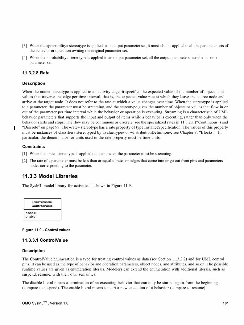
[3] When the «probability» stereotype is applied to an output parameter set, it must also be applied to all the parameter sets of the behavior or operation owning the original parameter set.
[4] When the «probability» stereotype is applied to an output parameter set, all the output parameters must be in some parameter set.
11.3.2.8 Rate
Description
When the «rate» stereotype is applied to an activity edge, it specifies the expected value of the number of objects and values that traverse the edge per time interval, that is, the expected value rate at which they leave the source node and arrive at the target node. It does not refer to the rate at which a value changes over time. When the stereotype is applied to a parameter, the parameter must be streaming, and the stereotype gives the number of objects or values that flow in or out of the parameter per time interval while the behavior or operation is executing. Streaming is a characteristic of UML behavior parameters that supports the input and output of items while a behavior is executing, rather than only when the behavior starts and stops. The flow may be continuous or discrete, see the specialized rates in 11.3.2.1 (“Continuous”) and “Discrete” on page 99. The «rate» stereotype has a rate property of type InstanceSpecification. The values of this property must be instances of classifiers stereotyped by «valueType» or «distributionDefinition», see Chapter 8, “Blocks.” In particular, the denominator for units used in the rate property must be time units.
Constraints[1] When the «rate» stereotype is applied to a parameter, the parameter must be streaming.
[2] The rate of a parameter must be less than or equal to rates on edges that come into or go out from pins and parameters nodes corresponding to the parameter.
11.3.3 Model LibrariesThe SysML model library for activities is shown in Figure 11.9.
11.3.3.1 ControlValue
Description
The ControlValue enumeration is a type for treating control values as data (see Section 11.3.2.2) and for UML control pins. It can be used as the type of behavior and operation parameters, object nodes, and attributes, and so on. The possible runtime values are given as enumeration literals. Modelers can extend the enumeration with additional literals, such as suspend, resume, with their own semantics.
The disable literal means a termination of an executing behavior that can only be started again from the beginning (compare to suspend). The enable literal means to start a new execution of a behavior (compare to resume).
Figure 11.9 - Control values.
disableenable
«enumeration»ControlValue
OMG SysMLTM , Version 1.0 101
Constraints[1] UML4SysML::ObjectNode::isControlType is true for object nodes with type ControlValue.
11.4 Usage ExamplesThe following examples illustrate modeling continuous systems (see Continuous Systems in Section 11.1.1). Figure 11.10 shows a simplified model of driving and braking in a car that has an automatic braking system. Turning the key on has a duration constraint specifying that this action lasts no more than 0.1 seconds. Turning the key on starts two behaviors, Driving and Braking. These behaviors execute until the key is turned off, using streaming parameters to communicate with other behaviors. The Driving behavior outputs a brake pressure continuously to the Braking behavior while both are executing, as indicated by the «continuous» rate and streaming properties (streaming is a characteristic of UML behavior parameters that supports the input and output of items while a behavior is executing, rather than only when the behavior starts and stops). Brake pressure information also flows to a control operator that outputs a control value to enable or disable the Monitor Traction behavior. No pins are used on Monitor Traction, so once it is enabled, the continuously arriving enable control values from the control operator have no effect, per UML semantics. When the brake pressure goes to zero, disable control values are emitted from the control operator. The first one disables the monitor, and the rest have no effect. While the monitor is enabled, it outputs a modulation frequency for applying the brakes as determined by the ABS system. The rake notations on the control operator and Monitor Traction indicate they are further defined by activities, as shown in Figures 11.11 and 11.12. An alternative notation for this activity decomposition is shown in Figure 11.13.
The duration constraint notation associated with the Turn Key To On action is supported by the UML Simple Time model. The Operate Car activity owns a duration constraint specifying that the "Turn Key To On" action lasts no more than 0.1 seconds. The concrete UML element used in this example is a DurationConstraint owned by Operate Car that constrains the Turn Key To On action. The DurationConstraint owns a DurationInterval, which specifies that the action is constrained to last between 0 seconds and 0.1 seconds (both being Duration expressions).
102 OMG SysMLTM , Version 1.0
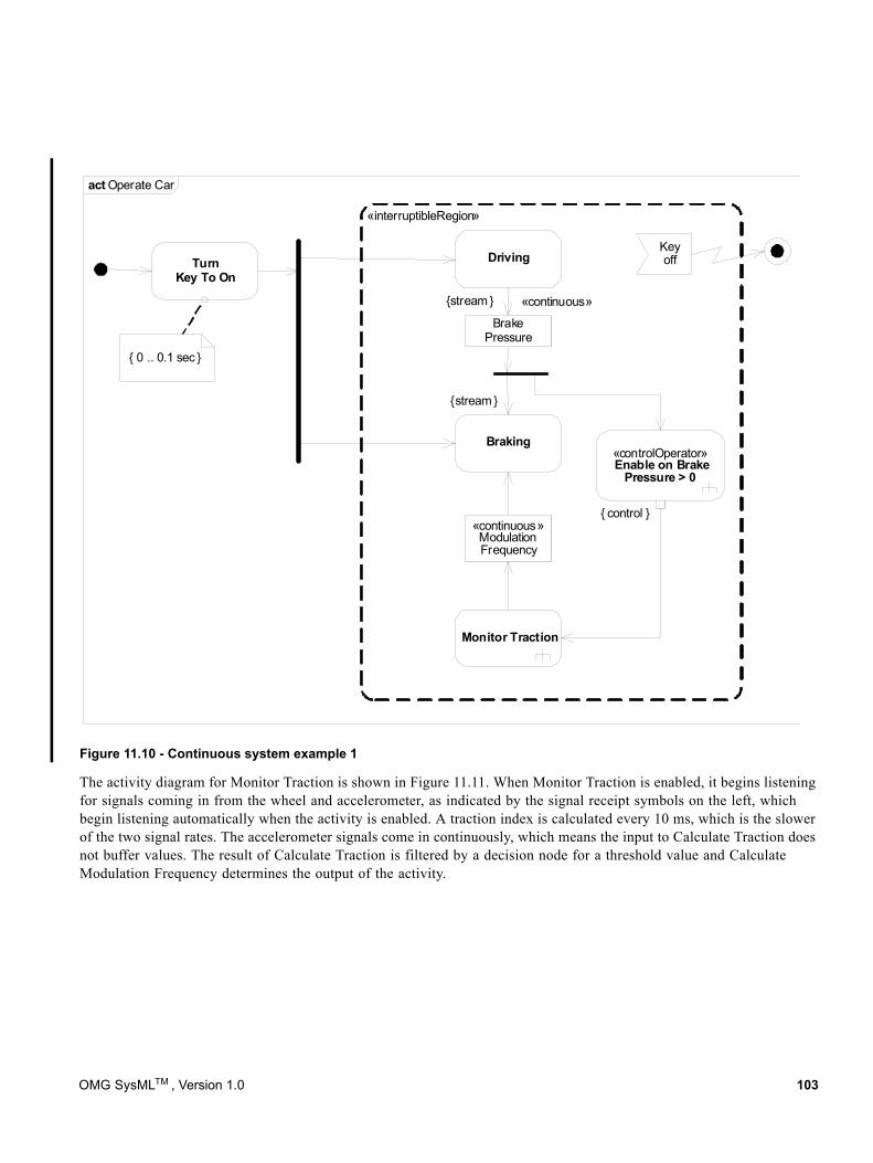
Figure 11.10 - Continuous system example 1
The activity diagram for Monitor Traction is shown in Figure 11.11. When Monitor Traction is enabled, it begins listening for signals coming in from the wheel and accelerometer, as indicated by the signal receipt symbols on the left, which begin listening automatically when the activity is enabled. A traction index is calculated every 10 ms, which is the slower of the two signal rates. The accelerometer signals come in continuously, which means the input to Calculate Traction does not buffer values. The result of Calculate Traction is filtered by a decision node for a threshold value and Calculate Modulation Frequency determines the output of the activity.
«interruptibleRegion»
Driving
Braking
Monitor Traction
{stream }
{stream }
TurnKey To On
Keyoff
BrakePressure
«continuous» Modulation Frequency
«controlOperator» Enable on Brake
Pressure > 0
«continuous»
act Operate Car
{ control }
{ 0 .. 0.1 sec }
OMG SysMLTM , Version 1.0 103
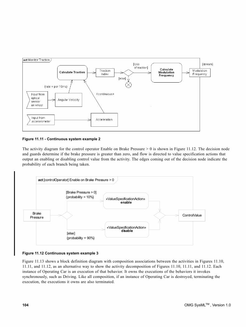
The activity diagram for the control operator Enable on Brake Pressure > 0 is shown in Figure 11.12. The decision node and guards determine if the brake pressure is greater than zero, and flow is directed to value specification actions that output an enabling or disabling control value from the activity. The edges coming out of the decision node indicate the probability of each branch being taken.
Figure 11.12 Continuous system example 3
Figure 11.13 shows a block definition diagram with composition associations between the activities in Figures 11.10, 11.11, and 11.12, as an alternative way to show the activity decomposition of Figures 11.10, 11.11, and 11.12. Each instance of Operating Car is an execution of that behavior. It owns the executions of the behaviors it invokes synchronously, such as Driving. Like all composition, if an instance of Operating Car is destroyed, terminating the execution, the executions it owns are also terminated.
Figure 11.11 - Continuous system example 2
act [controlOperator] Enable on Brake Pressure > 0
BrakePressure ControlValue
[Brake Pressure > 0]
«ValueSpecificationAction» enable
«ValueSpecificationAction» disable
[else]{probability = 90%}
{probability = 10%}
104 OMG SysMLTM , Version 1.0
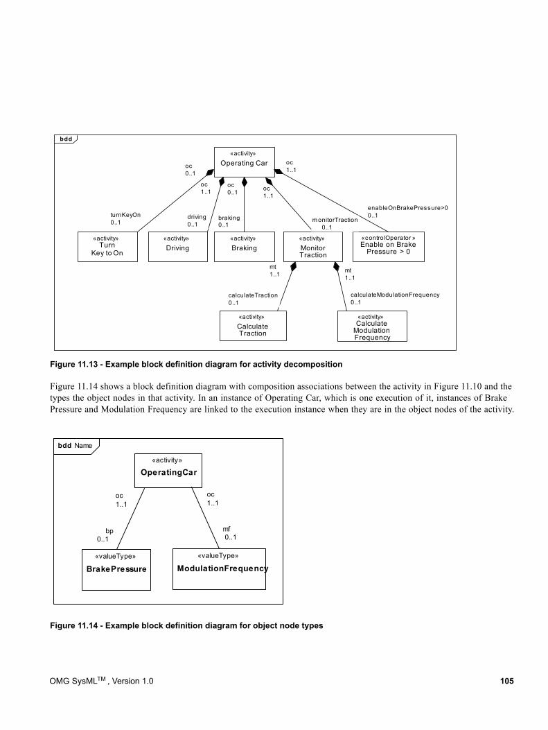
Figure 11.14 shows a block definition diagram with composition associations between the activity in Figure 11.10 and the types the object nodes in that activity. In an instance of Operating Car, which is one execution of it, instances of Brake Pressure and Modulation Frequency are linked to the execution instance when they are in the object nodes of the activity.
Figure 11.14 - Example block definition diagram for object node types
Figure 11.13 - Example block definition diagram for activity decomposition
mt1..1
«activity»
Driving«activity»
Braking«activity»
MonitorTraction
«activity»Turn
Key to On
«controlOperator »Enable on Brake
Pressure > 0
«activity»CalculateTraction
«activity»Calculate
ModulationFrequency
«activity»
Operating Car
enableOnBrakePressure>00..1
calculateTraction0..1
calculateModulationFrequency0..1
oc0..1
oc1..1
oc0..1 oc
1..1
oc1..1
m onitorTraction 0..1
driving0..1
turnKeyOn0..1
mt1..1
braking0..1
bdd
«activity»
Operating Car
oc1..1
oc1..1
mf 0..1
bp0..1
«valueType»
BrakePressure«valueType»
ModulationFrequency
bdd Name
OMG SysMLTM , Version 1.0 105

106 OMG SysMLTM , Version 1.0
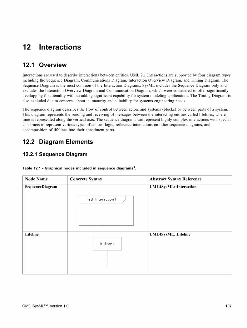
12 Interactions
12.1 OverviewInteractions are used to describe interactions between entities. UML 2.1 Interactions are supported by four diagram types including the Sequence Diagram, Communications Diagram, Interaction Overview Diagram, and Timing Diagram. The Sequence Diagram is the most common of the Interaction Diagrams. SysML includes the Sequence Diagram only and excludes the Interaction Overview Diagram and Communication Diagram, which were considered to offer significantly overlapping functionality without adding significant capability for system modeling applications. The Timing Diagram is also excluded due to concerns about its maturity and suitability for systems engineering needs.
The sequence diagram describes the flow of control between actors and systems (blocks) or between parts of a system. This diagram represents the sending and receiving of messages between the interacting entities called lifelines, where time is represented along the vertical axis. The sequence diagrams can represent highly complex interactions with special constructs to represent various types of control logic, reference interactions on other sequence diagrams, and decomposition of lifelines into their constituent parts.
12.2 Diagram Elements
12.2.1 Sequence Diagram
Table 12.1 - Graphical nodes included in sequence diagrams1.
Node Name Concrete Syntax Abstract Syntax Reference
SequenceDiagram UML4SysML::Interaction
Lifeline UML4SysML::Lifeline
sd In teraction1
b1:Block1
OMG SysMLTM, Version 1.0 107
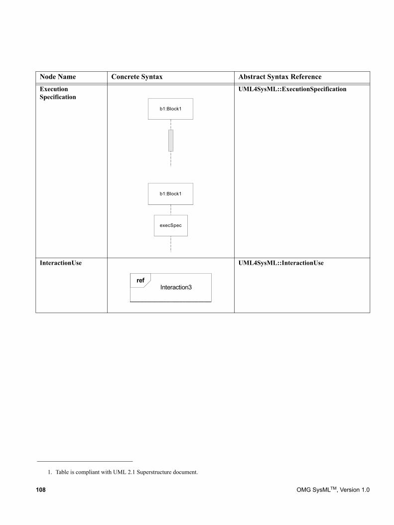
1. Table is compliant with UML 2.1 Superstructure document.
Execution Specification
UML4SysML::ExecutionSpecification
InteractionUse UML4SysML::InteractionUse
Node Name Concrete Syntax Abstract Syntax Reference
b1:Block1
execSpec
b1:Block1
refInteraction3
108 OMG SysMLTM, Version 1.0
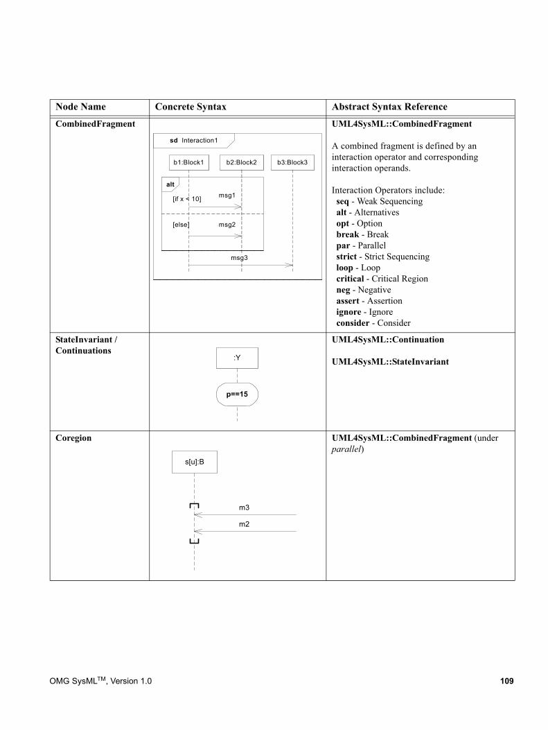
CombinedFragment UML4SysML::CombinedFragment
A combined fragment is defined by an interaction operator and corresponding interaction operands.
Interaction Operators include: seq - Weak Sequencing alt - Alternatives opt - Option break - Break par - Parallel strict - Strict Sequencing loop - Loop critical - Critical Region neg - Negative assert - Assertion ignore - Ignore consider - Consider
StateInvariant / Continuations
UML4SysML::Continuation
UML4SysML::StateInvariant
Coregion UML4SysML::CombinedFragment (under parallel)
Node Name Concrete Syntax Abstract Syntax Reference
sd Interaction1
msg2
msg1[if x < 10]
[else]
alt
b1:Block1 b2:Block2 b3:Block3
msg3
:Y
p==15
s[u]:B
m3
m2
OMG SysMLTM, Version 1.0 109
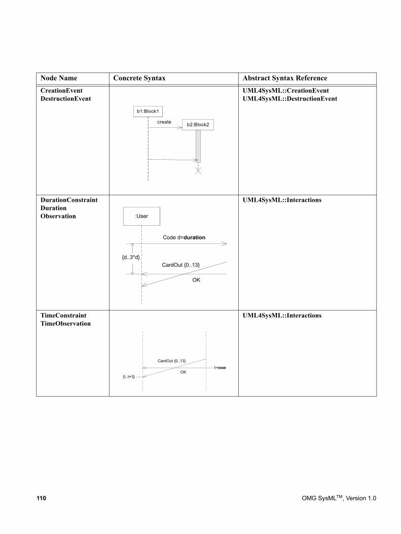
CreationEventDestructionEvent
UML4SysML::CreationEventUML4SysML::DestructionEvent
DurationConstraintDuration Observation
UML4SysML::Interactions
TimeConstraintTimeObservation
UML4SysML::Interactions
Node Name Concrete Syntax Abstract Syntax Reference
b1:Block1
b2:Block2create
:User
Code d=duration
CardOut {0..13}
OK
{d..3*d}
CardOut {0..13}
OKt=now
{t..t+3}
110 OMG SysMLTM, Version 1.0
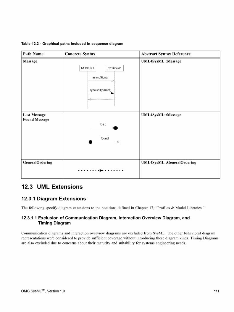
Table 12.2 - Graphical paths included in sequence diagram
12.3 UML Extensions
12.3.1 Diagram ExtensionsThe following specify diagram extensions to the notations defined in Chapter 17, “Profiles & Model Libraries.”
12.3.1.1 Exclusion of Communication Diagram, Interaction Overview Diagram, and Timing Diagram
Communication diagrams and interaction overview diagrams are excluded from SysML. The other behavioral diagram representations were considered to provide sufficient coverage without introducing these diagram kinds. Timing Diagrams are also excluded due to concerns about their maturity and suitability for systems engineering needs.
Path Name Concrete Syntax Abstract Syntax Reference
Message UML4SysML::Message
Lost MessageFound Message
UML4SysML::Message
GeneralOrdering UML4SysML::GeneralOrdering
asyncSignal
syncCall(param)
b1:Block1 b2:Block2
lost
found
OMG SysMLTM, Version 1.0 111
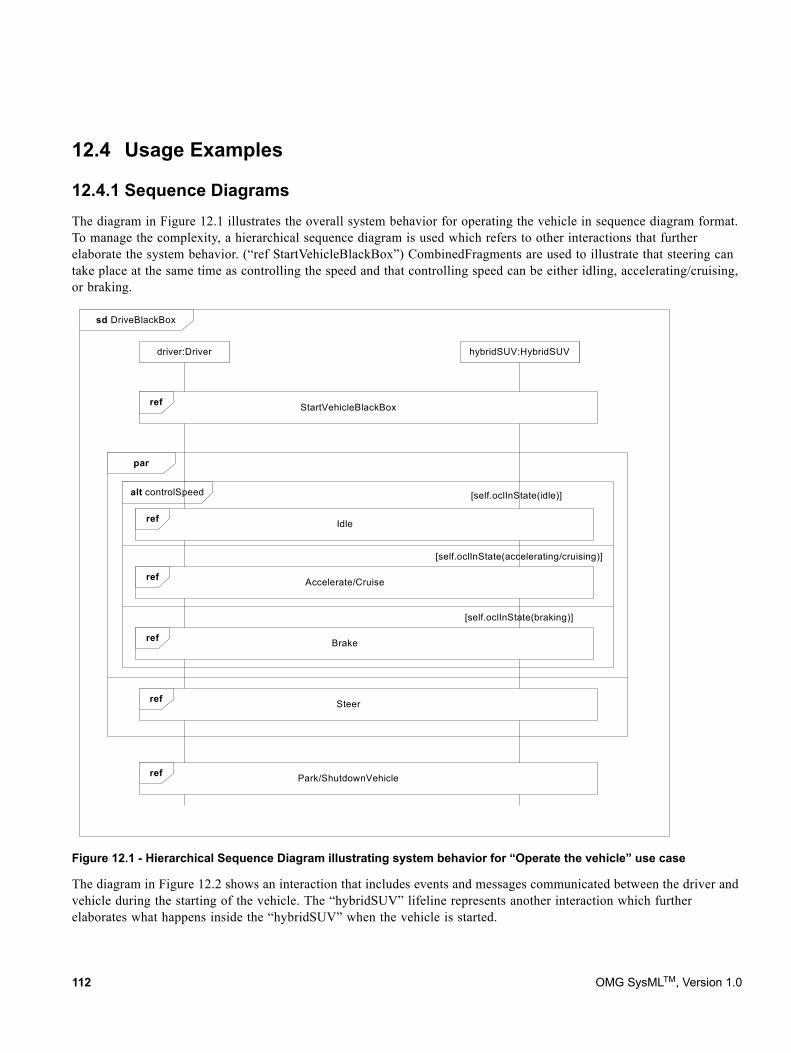
12.4 Usage Examples
12.4.1 Sequence DiagramsThe diagram in Figure 12.1 illustrates the overall system behavior for operating the vehicle in sequence diagram format. To manage the complexity, a hierarchical sequence diagram is used which refers to other interactions that further elaborate the system behavior. (“ref StartVehicleBlackBox”) CombinedFragments are used to illustrate that steering can take place at the same time as controlling the speed and that controlling speed can be either idling, accelerating/cruising, or braking.
Figure 12.1 - Hierarchical Sequence Diagram illustrating system behavior for “Operate the vehicle” use case
The diagram in Figure 12.2 shows an interaction that includes events and messages communicated between the driver and vehicle during the starting of the vehicle. The “hybridSUV” lifeline represents another interaction which further elaborates what happens inside the “hybridSUV” when the vehicle is started.
sd DriveBlackBox
par
alt controlSpeed
driver:Driver hybridSUV:HybridSUV
ref StartVehicleBlackBox
ref Park/ShutdownVehicle
ref Steer
ref Accelerate/Cruise
ref Brake
ref Idle
[self.oclInState(idle)]
[self.oclInState(accelerating/cruising)]
[self.oclInState(braking)]
112 OMG SysMLTM, Version 1.0
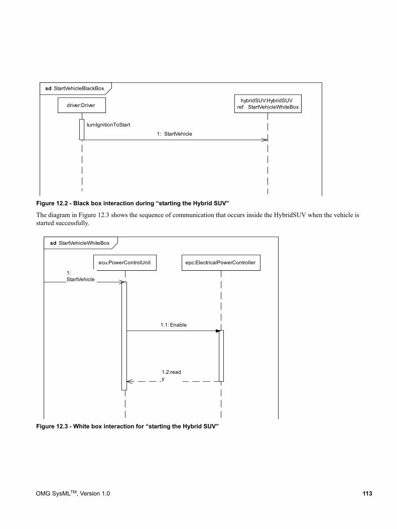
Figure 12.2 - Black box interaction during “starting the Hybrid SUV”
The diagram in Figure 12.3 shows the sequence of communication that occurs inside the HybridSUV when the vehicle is started successfully.
Figure 12.3 - White box interaction for “starting the Hybrid SUV”
sd StartVehicleBlackBox
driver:DriverhybridSUV:HybridSUV
ref StartVehicleWhiteBox
1: StartVehicle
turnIgnitionToStart
sd StartVehicleWhiteBox
ecu:PowerControlUnit epc:ElectricalPowerController
1.1: Enable
1:StartVehicle
1.2:ready
OMG SysMLTM, Version 1.0 113

114 OMG SysMLTM, Version 1.0
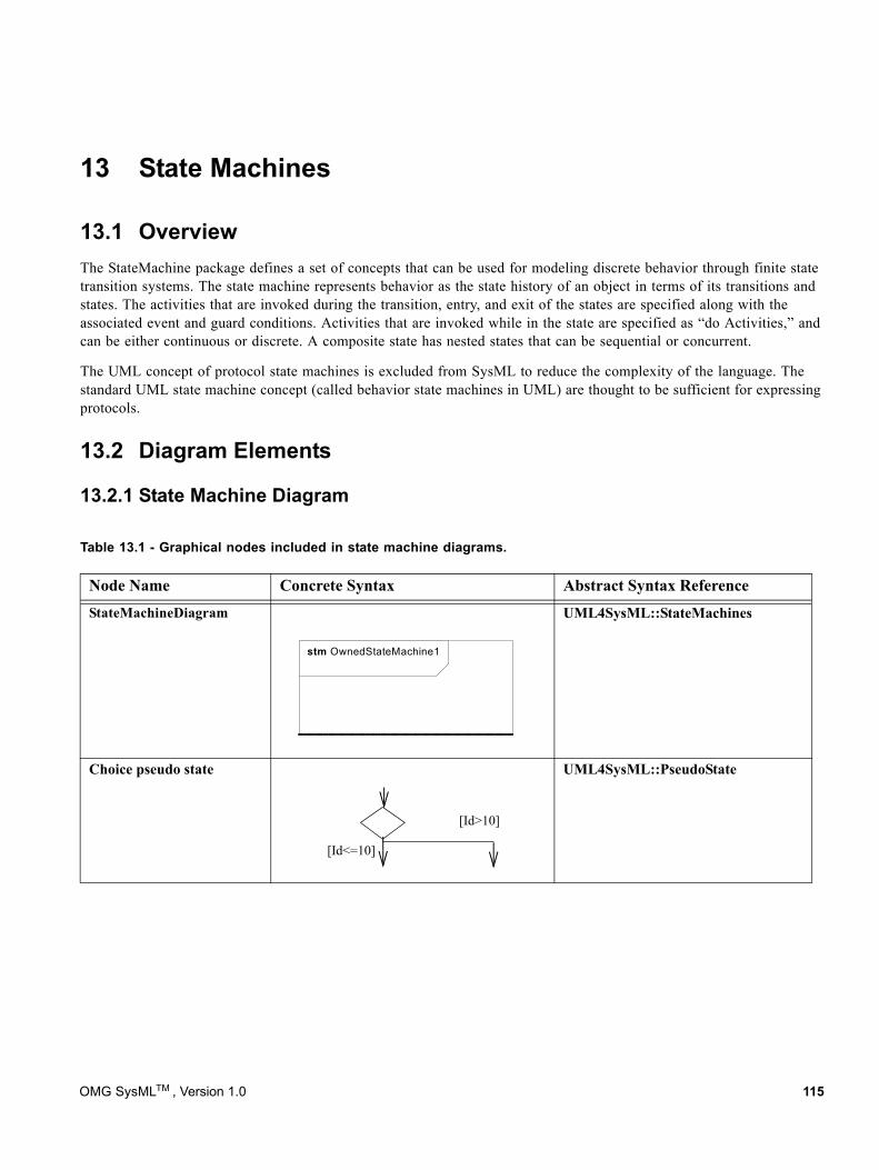
13 State Machines
13.1 OverviewThe StateMachine package defines a set of concepts that can be used for modeling discrete behavior through finite state transition systems. The state machine represents behavior as the state history of an object in terms of its transitions and states. The activities that are invoked during the transition, entry, and exit of the states are specified along with the associated event and guard conditions. Activities that are invoked while in the state are specified as “do Activities,” and can be either continuous or discrete. A composite state has nested states that can be sequential or concurrent.
The UML concept of protocol state machines is excluded from SysML to reduce the complexity of the language. The standard UML state machine concept (called behavior state machines in UML) are thought to be sufficient for expressing protocols.
13.2 Diagram Elements
13.2.1 State Machine Diagram
Table 13.1 - Graphical nodes included in state machine diagrams.
Node Name Concrete Syntax Abstract Syntax Reference
StateMachineDiagram UML4SysML::StateMachines
Choice pseudo state UML4SysML::PseudoState
stm OwnedStateMachine1
[Id>10]
[Id<=10]
OMG SysMLTM , Version 1.0 115
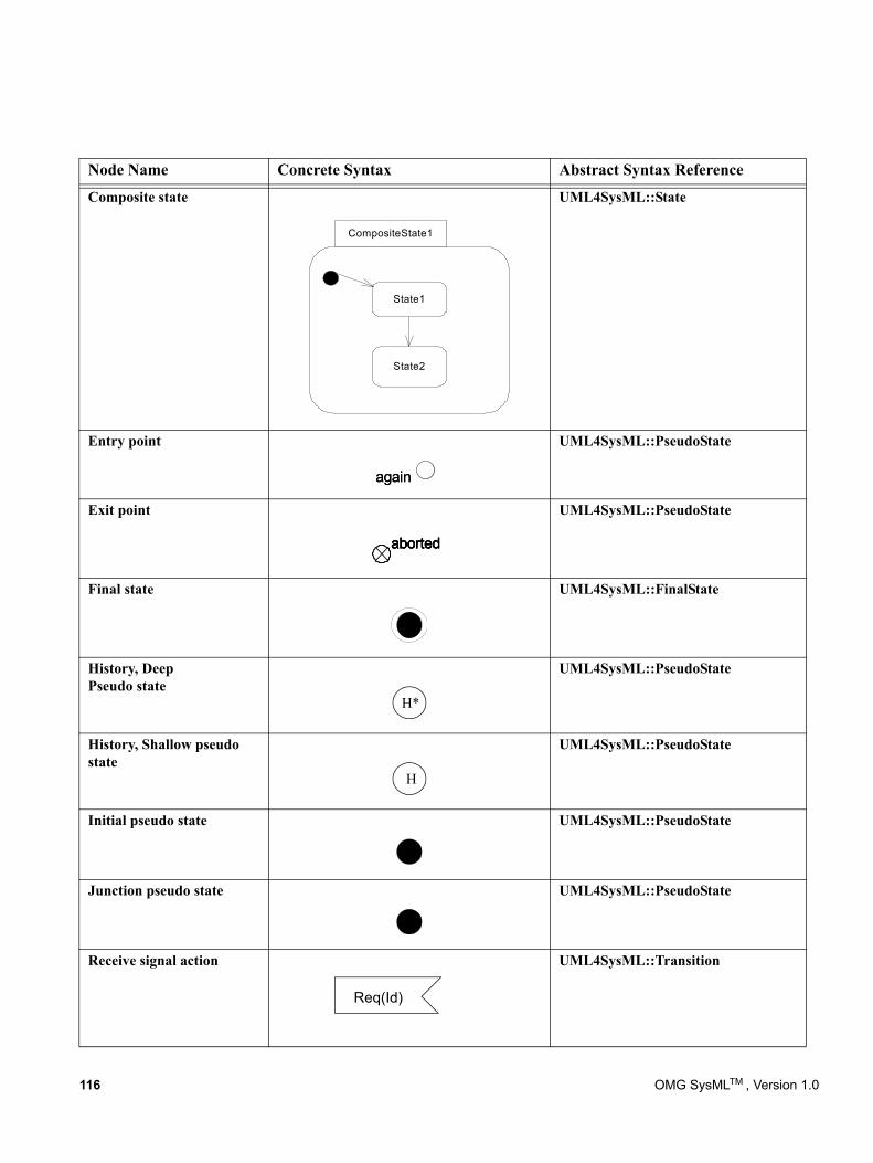
Composite state UML4SysML::State
Entry point UML4SysML::PseudoState
Exit point UML4SysML::PseudoState
Final state UML4SysML::FinalState
History, DeepPseudo state
UML4SysML::PseudoState
History, Shallow pseudo state
UML4SysML::PseudoState
Initial pseudo state UML4SysML::PseudoState
Junction pseudo state UML4SysML::PseudoState
Receive signal action UML4SysML::Transition
Node Name Concrete Syntax Abstract Syntax Reference
CompositeState1
State1
State2
againagain
abortedabortedabortedaborted
H*
H
Req(Id)
116 OMG SysMLTM , Version 1.0
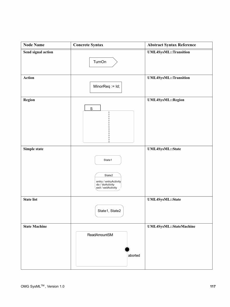
Send signal action UML4SysML::Transition
Action UML4SysML::Transition
Region UML4SysML::Region
Simple state UML4SysML::State
State list UML4SysML::State
State Machine UML4SysML::StateMachine
Node Name Concrete Syntax Abstract Syntax Reference
TurnOn
MinorReq := Id;
S
State1
State2
entry / entryActivitydo / doActivityexit / exitActivity
State1, State2
ReadAmountSM
aborted
OMG SysMLTM , Version 1.0 117
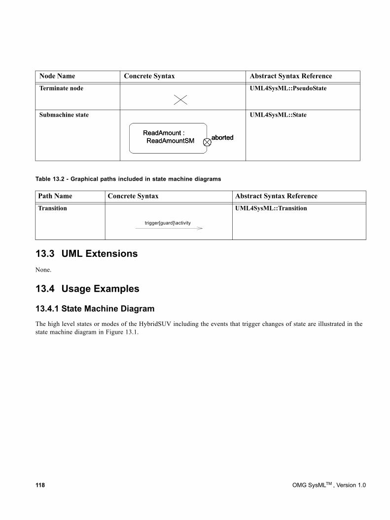
Table 13.2 - Graphical paths included in state machine diagrams
13.3 UML ExtensionsNone.
13.4 Usage Examples
13.4.1 State Machine DiagramThe high level states or modes of the HybridSUV including the events that trigger changes of state are illustrated in the state machine diagram in Figure 13.1.
Terminate node UML4SysML::PseudoState
Submachine state UML4SysML::State
Path Name Concrete Syntax Abstract Syntax Reference
Transition UML4SysML::Transition
Node Name Concrete Syntax Abstract Syntax Reference
ReadAmount :ReadAmountSM abortedaborted
ReadAmount :ReadAmountSM abortedaborted
trigger[guard]\activity
118 OMG SysMLTM , Version 1.0
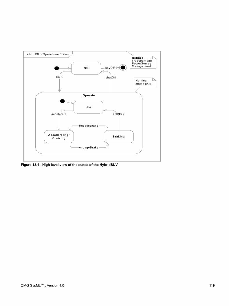
Figure 13.1 - High level view of the states of the HybridSUV
stm HSUVO perationalS tates
O perate
Idle
Accellerating/Cruising Braking
engageBrake
accelerate stopped
releaseBrake
shutO ff
O ff
start
keyO ff
Refines«requirem ent»PowerSourceM anagem ent
Nom inalstates only
OMG SysMLTM , Version 1.0 119

120 OMG SysMLTM , Version 1.0
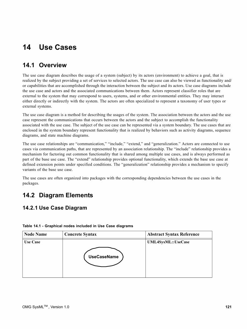
14 Use Cases
14.1 OverviewThe use case diagram describes the usage of a system (subject) by its actors (environment) to achieve a goal, that is realized by the subject providing a set of services to selected actors. The use case can also be viewed as functionality and/or capabilities that are accomplished through the interaction between the subject and its actors. Use case diagrams include the use case and actors and the associated communications between them. Actors represent classifier roles that are external to the system that may correspond to users, systems, and or other environmental entities. They may interact either directly or indirectly with the system. The actors are often specialized to represent a taxonomy of user types or external systems.
The use case diagram is a method for describing the usages of the system. The association between the actors and the use case represent the communications that occurs between the actors and the subject to accomplish the functionality associated with the use case. The subject of the use case can be represented via a system boundary. The use cases that are enclosed in the system boundary represent functionality that is realized by behaviors such as activity diagrams, sequence diagrams, and state machine diagrams.
The use case relationships are “communication,” “include,” “extend,” and “generalization.” Actors are connected to use cases via communication paths, that are represented by an association relationship. The “include” relationship provides a mechanism for factoring out common functionality that is shared among multiple use cases, and is always performed as part of the base use case. The “extend” relationship provides optional functionality, which extends the base use case at defined extension points under specified conditions. The “generalization” relationship provides a mechanism to specify variants of the base use case.
The use cases are often organized into packages with the corresponding dependencies between the use cases in the packages.
14.2 Diagram Elements
14.2.1 Use Case Diagram
Table 14.1 - Graphical nodes included in Use Case diagrams
Node Name Concrete Syntax Abstract Syntax Reference
Use Case UML4SysML::UseCase
UseCaseName
OMG SysMLTM , Version 1.0 121
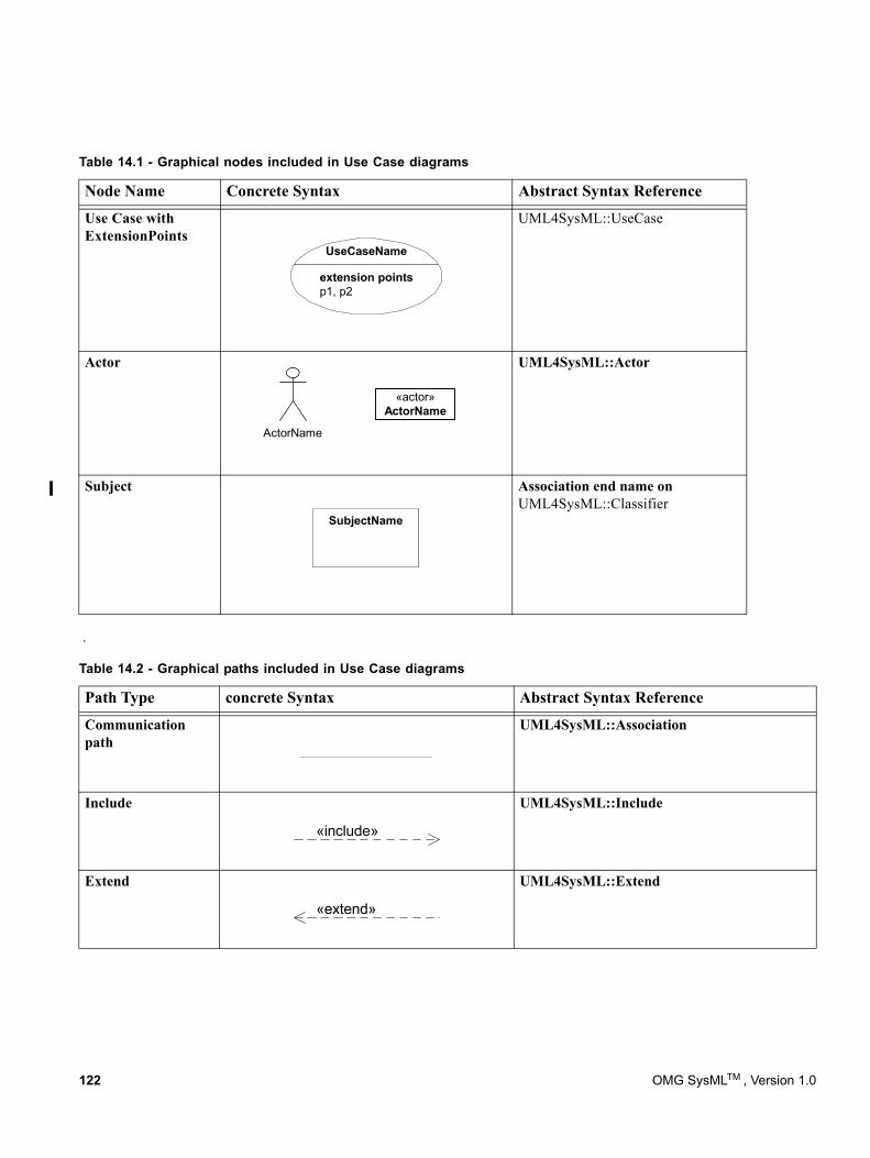
.
Use Case with ExtensionPoints
UML4SysML::UseCase
Actor UML4SysML::Actor
Subject Association end name on UML4SysML::Classifier
Table 14.2 - Graphical paths included in Use Case diagrams
Path Type concrete Syntax Abstract Syntax Reference
Communication path
UML4SysML::Association
Include UML4SysML::Include
Extend UML4SysML::Extend
Table 14.1 - Graphical nodes included in Use Case diagrams
Node Name Concrete Syntax Abstract Syntax Reference
extension pointsp1, p2
UseCaseName
«actor»ActorName
ActorName
SubjectName
«include»
«extend»
122 OMG SysMLTM , Version 1.0
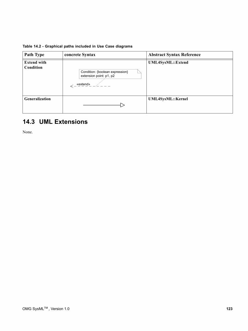
14.3 UML ExtensionsNone.
Extend with Condition
UML4SysML::Extend
Generalization UML4SysML::Kernel
Table 14.2 - Graphical paths included in Use Case diagrams
Path Type concrete Syntax Abstract Syntax Reference
«extend»
Condition: {boolean expression}extension point: p1, p2
OMG SysMLTM , Version 1.0 123
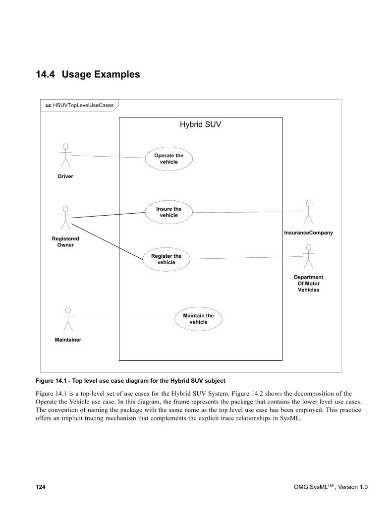
14.4 Usage Examples
Figure 14.1 - Top level use case diagram for the Hybrid SUV subject
Figure 14.1 is a top-level set of use cases for the Hybrid SUV System. Figure 14.2 shows the decomposition of the Operate the Vehicle use case. In this diagram, the frame represents the package that contains the lower level use cases. The convention of naming the package with the same name as the top level use case has been employed. This practice offers an implicit tracing mechanism that complements the explicit trace relationships in SysML.
uc HSUVTopLevelUseCases
Hybrid SUV
Driver
Operate thevehicle
Maintain thevehicle
Maintainer
Insure thevehicle
Register thevehicle
InsuranceCompany
DepartmentOf MotorVehicles
RegisteredOwner
124 OMG SysMLTM , Version 1.0
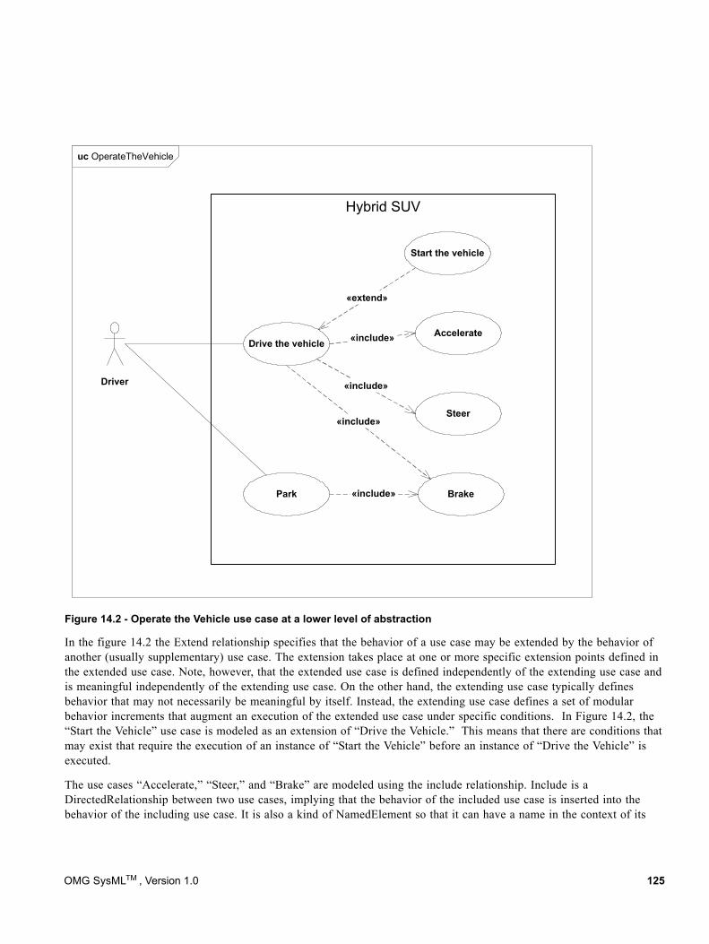
Figure 14.2 - Operate the Vehicle use case at a lower level of abstraction
In the figure 14.2 the Extend relationship specifies that the behavior of a use case may be extended by the behavior of another (usually supplementary) use case. The extension takes place at one or more specific extension points defined in the extended use case. Note, however, that the extended use case is defined independently of the extending use case and is meaningful independently of the extending use case. On the other hand, the extending use case typically defines behavior that may not necessarily be meaningful by itself. Instead, the extending use case defines a set of modular behavior increments that augment an execution of the extended use case under specific conditions. In Figure 14.2, the “Start the Vehicle” use case is modeled as an extension of “Drive the Vehicle.” This means that there are conditions that may exist that require the execution of an instance of “Start the Vehicle” before an instance of “Drive the Vehicle” is executed.
The use cases “Accelerate,” “Steer,” and “Brake” are modeled using the include relationship. Include is a DirectedRelationship between two use cases, implying that the behavior of the included use case is inserted into the behavior of the including use case. It is also a kind of NamedElement so that it can have a name in the context of its
uc OperateTheVehicle
Hybrid SUV
Driver
AccelerateDrive the vehicle
Steer
Brake
«include»
«include»
«include»
Park «include»
«extend»
Start the vehicle
OMG SysMLTM , Version 1.0 125
owning use case. The including use case may only depend on the result (value) of the included use case. This value is obtained as a result of the execution of the included use case. This means that “Accelerate,” “Steer,” and “Brake” are all part of the normal process of executing an instance of “Drive the Car.”
In many situations, the use of the Include and Extend relationships is subjective and may be reversed, based on the approach of an individual modeler.
126 OMG SysMLTM , Version 1.0

Part IV - Crosscutting Constructs
This Part specifies crosscutting constructs that apply to both structure and behavior. These constructs are defined in the following chapters:
Chapter 15 - Allocations - defines a basic allocation relationship that can be used to allocate a set of model elements to another, such as allocating behavior to structure or allocating logical to physical components.
Chapter 16 - Requirements - specifies constructs for system requirements and their relationships.
Chapter 17 - Profiles and Model Libraries - specifies the approach to further customize and extend SysML for specific applications.
OMG SysMLTM , Version 1.0 127

128 OMG SysMLTM , Version 1.0
15 Allocations
15.1 OverviewAllocation is the term used by systems engineers to denote the organized cross-association (mapping) of elements within the various structures or hierarchies of a user model. The concept of “allocation” requires flexibility suitable for abstract system specification, rather than a particular constrained method of system or software design. System modelers often associate various elements in a user model in abstract, preliminary, and sometimes tentative ways. Allocations can be used early in the design as a precursor to more detailed rigorous specifications and implementations. The allocation relationship can provide an effective means for navigating the model by establishing cross relationships, and ensuring the various parts of the model are properly integrated.
This chapter does not try to limit the use of the term “allocation,” but provides a basic capability to support allocation in the broadest sense. It does include some specific subclasses of allocation for allocating behavior, structure, and flows. A typical example is the allocation of activities to blocks (e.g., functions to components). This chapter specifies an extension for an allocation relationship and selected subclasses of allocation, along with the notation to represent allocations in a SysML model.
15.2 Diagram ElementsThe diagram elements defined in this chapter may be shown on some or all SysML diagram types, in addition to the diagram elements that are specific for each diagram type.
OMG SysMLTM , Version 1.0 129
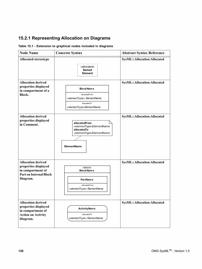
15.2.1 Representing Allocation on Diagrams
Table 15.1 - Extension to graphical nodes included in diagrams
Node Name Concrete Syntax Abstract Syntax Reference
Allocated stereotype
«allocated»Named
Element
SysML::Allocation:Allocated
Allocation derived properties displayed in compartment of a Block.
«elementType»ElementName
«elementType» ElementName
BlockNam e
allocatedFrom
allocatedTo
SysML::Allocation:Allocated
Allocation derived properties displayed in Comment. allocatedFrom
«elementType»ElementNameallocatedTo«elementType»ElementName
ElementName
SysML::Allocation:Allocated
Allocation derived properties displayed in compartment of Part on Internal Block Diagram.
«block»BlockNam e
«elementType» ElementName
PartNam e
allocatedFrom
SysML::Allocation:Allocated
Allocation derived properties displayed in compartment of Action on Activity Diagram. «elementType» ElementName
ActivityNam e
allocatedTo
SysML::Allocation:Allocated
130 OMG SysMLTM , Version 1.0
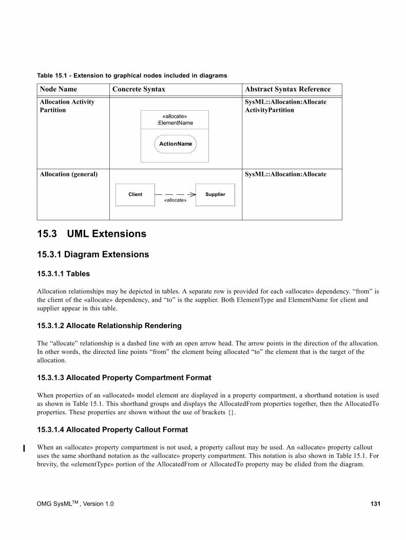
15.3 UML Extensions
15.3.1 Diagram Extensions
15.3.1.1 Tables
Allocation relationships may be depicted in tables. A separate row is provided for each «allocate» dependency. “from” is the client of the «allocate» dependency, and “to” is the supplier. Both ElementType and ElementName for client and supplier appear in this table.
15.3.1.2 Allocate Relationship Rendering
The “allocate” relationship is a dashed line with an open arrow head. The arrow points in the direction of the allocation. In other words, the directed line points “from” the element being allocated “to” the element that is the target of the allocation.
15.3.1.3 Allocated Property Compartment Format
When properties of an «allocated» model element are displayed in a property compartment, a shorthand notation is used as shown in Table 15.1. This shorthand groups and displays the AllocatedFrom properties together, then the AllocatedTo properties. These properties are shown without the use of brackets {}.
15.3.1.4 Allocated Property Callout Format
When an «allocate» property compartment is not used, a property callout may be used. An «allocate» property callout uses the same shorthand notation as the «allocate» property compartment. This notation is also shown in Table 15.1. For brevity, the «elementType» portion of the AllocatedFrom or AllocatedTo property may be elided from the diagram.
Allocation Activity Partition «allocate»
:ElementName
ActionName
SysML::Allocation:Allocate ActivityPartition
Allocation (general)
«allocate»Client Supplier
SysML::Allocation:Allocate
Table 15.1 - Extension to graphical nodes included in diagrams
Node Name Concrete Syntax Abstract Syntax Reference
OMG SysMLTM , Version 1.0 131
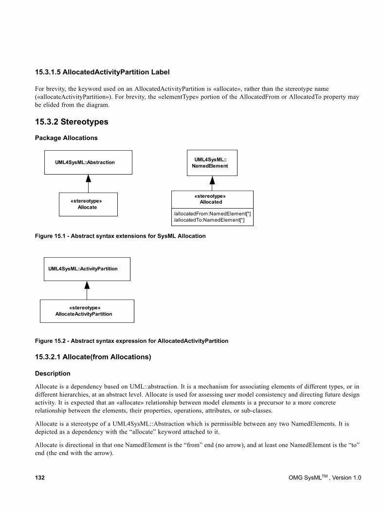
15.3.1.5 AllocatedActivityPartition Label
For brevity, the keyword used on an AllocatedActivityPartition is «allocate», rather than the stereotype name («allocateActivityPartition»). For brevity, the «elementType» portion of the AllocatedFrom or AllocatedTo property may be elided from the diagram.
15.3.2 Stereotypes
Package Allocations
«stereotype»Allocate
UML4SysML::Abstraction UML4SysML::NamedElement
/allocatedFrom:NamedElement[*]/allocatedTo:NamedElement[*]
«stereotype»Allocated
Figure 15.1 - Abstract syntax extensions for SysML Allocation
Figure 15.2 - Abstract syntax expression for AllocatedActivityPartition
15.3.2.1 Allocate(from Allocations)
Description
Allocate is a dependency based on UML::abstraction. It is a mechanism for associating elements of different types, or in different hierarchies, at an abstract level. Allocate is used for assessing user model consistency and directing future design activity. It is expected that an «allocate» relationship between model elements is a precursor to a more concrete relationship between the elements, their properties, operations, attributes, or sub-classes.
Allocate is a stereotype of a UML4SysML::Abstraction which is permissible between any two NamedElements. It is depicted as a dependency with the “allocate” keyword attached to it.
Allocate is directional in that one NamedElement is the “from” end (no arrow), and at least one NamedElement is the “to” end (the end with the arrow).
UML4SysML::ActivityPartition
«stereotype»AllocateActivityPartition
132 OMG SysMLTM , Version 1.0
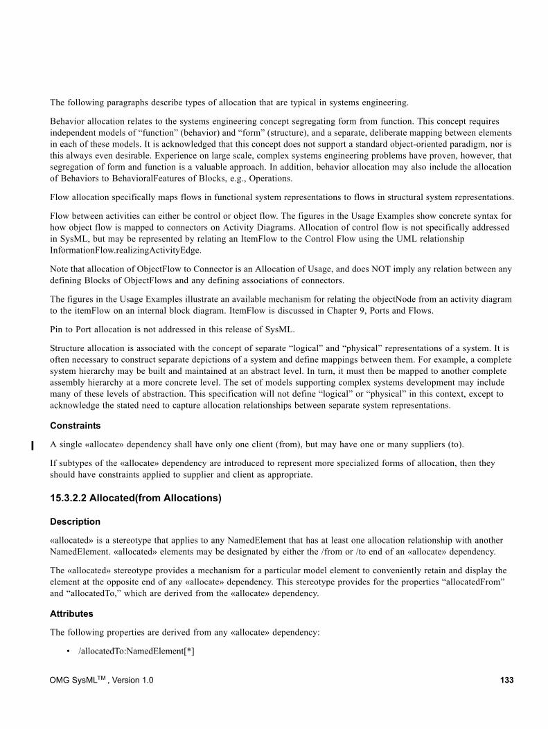
The following paragraphs describe types of allocation that are typical in systems engineering.
Behavior allocation relates to the systems engineering concept segregating form from function. This concept requires independent models of “function” (behavior) and “form” (structure), and a separate, deliberate mapping between elements in each of these models. It is acknowledged that this concept does not support a standard object-oriented paradigm, nor is this always even desirable. Experience on large scale, complex systems engineering problems have proven, however, that segregation of form and function is a valuable approach. In addition, behavior allocation may also include the allocation of Behaviors to BehavioralFeatures of Blocks, e.g., Operations.
Flow allocation specifically maps flows in functional system representations to flows in structural system representations.
Flow between activities can either be control or object flow. The figures in the Usage Examples show concrete syntax for how object flow is mapped to connectors on Activity Diagrams. Allocation of control flow is not specifically addressed in SysML, but may be represented by relating an ItemFlow to the Control Flow using the UML relationship InformationFlow.realizingActivityEdge.
Note that allocation of ObjectFlow to Connector is an Allocation of Usage, and does NOT imply any relation between any defining Blocks of ObjectFlows and any defining associations of connectors.
The figures in the Usage Examples illustrate an available mechanism for relating the objectNode from an activity diagram to the itemFlow on an internal block diagram. ItemFlow is discussed in Chapter 9, Ports and Flows.
Pin to Port allocation is not addressed in this release of SysML.
Structure allocation is associated with the concept of separate “logical” and “physical” representations of a system. It is often necessary to construct separate depictions of a system and define mappings between them. For example, a complete system hierarchy may be built and maintained at an abstract level. In turn, it must then be mapped to another complete assembly hierarchy at a more concrete level. The set of models supporting complex systems development may include many of these levels of abstraction. This specification will not define “logical” or “physical” in this context, except to acknowledge the stated need to capture allocation relationships between separate system representations.
Constraints
A single «allocate» dependency shall have only one client (from), but may have one or many suppliers (to).
If subtypes of the «allocate» dependency are introduced to represent more specialized forms of allocation, then they should have constraints applied to supplier and client as appropriate.
15.3.2.2 Allocated(from Allocations)
Description
«allocated» is a stereotype that applies to any NamedElement that has at least one allocation relationship with another NamedElement. «allocated» elements may be designated by either the /from or /to end of an «allocate» dependency.
The «allocated» stereotype provides a mechanism for a particular model element to conveniently retain and display the element at the opposite end of any «allocate» dependency. This stereotype provides for the properties “allocatedFrom” and “allocatedTo,” which are derived from the «allocate» dependency.
Attributes
The following properties are derived from any «allocate» dependency:
• /allocatedTo:NamedElement[*]
OMG SysMLTM , Version 1.0 133
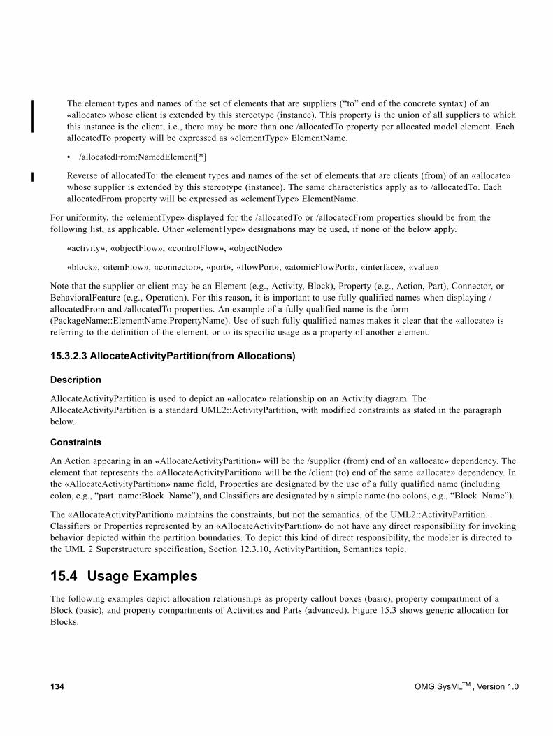
The element types and names of the set of elements that are suppliers (“to” end of the concrete syntax) of an «allocate» whose client is extended by this stereotype (instance). This property is the union of all suppliers to which this instance is the client, i.e., there may be more than one /allocatedTo property per allocated model element. Each allocatedTo property will be expressed as «elementType» ElementName.
• /allocatedFrom:NamedElement[*]
Reverse of allocatedTo: the element types and names of the set of elements that are clients (from) of an «allocate» whose supplier is extended by this stereotype (instance). The same characteristics apply as to /allocatedTo. Each allocatedFrom property will be expressed as «elementType» ElementName.
For uniformity, the «elementType» displayed for the /allocatedTo or /allocatedFrom properties should be from the following list, as applicable. Other «elementType» designations may be used, if none of the below apply.
«activity», «objectFlow», «controlFlow», «objectNode»
«block», «itemFlow», «connector», «port», «flowPort», «atomicFlowPort», «interface», «value»
Note that the supplier or client may be an Element (e.g., Activity, Block), Property (e.g., Action, Part), Connector, or BehavioralFeature (e.g., Operation). For this reason, it is important to use fully qualified names when displaying /allocatedFrom and /allocatedTo properties. An example of a fully qualified name is the form (PackageName::ElementName.PropertyName). Use of such fully qualified names makes it clear that the «allocate» is referring to the definition of the element, or to its specific usage as a property of another element.
15.3.2.3 AllocateActivityPartition(from Allocations)
Description
AllocateActivityPartition is used to depict an «allocate» relationship on an Activity diagram. The AllocateActivityPartition is a standard UML2::ActivityPartition, with modified constraints as stated in the paragraph below.
Constraints
An Action appearing in an «AllocateActivityPartition» will be the /supplier (from) end of an «allocate» dependency. The element that represents the «AllocateActivityPartition» will be the /client (to) end of the same «allocate» dependency. In the «AllocateActivityPartition» name field, Properties are designated by the use of a fully qualified name (including colon, e.g., “part_name:Block_Name”), and Classifiers are designated by a simple name (no colons, e.g., “Block_Name”).
The «AllocateActivityPartition» maintains the constraints, but not the semantics, of the UML2::ActivityPartition. Classifiers or Properties represented by an «AllocateActivityPartition» do not have any direct responsibility for invoking behavior depicted within the partition boundaries. To depict this kind of direct responsibility, the modeler is directed to the UML 2 Superstructure specification, Section 12.3.10, ActivityPartition, Semantics topic.
15.4 Usage ExamplesThe following examples depict allocation relationships as property callout boxes (basic), property compartment of a Block (basic), and property compartments of Activities and Parts (advanced). Figure 15.3 shows generic allocation for Blocks.
134 OMG SysMLTM , Version 1.0
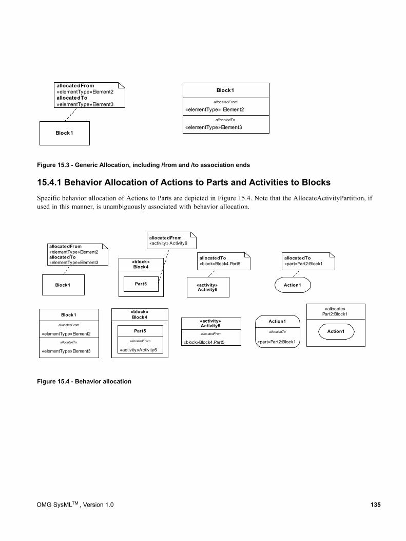
Figure 15.3 - Generic Allocation, including /from and /to association ends
15.4.1 Behavior Allocation of Actions to Parts and Activities to BlocksSpecific behavior allocation of Actions to Parts are depicted in Figure 15.4. Note that the AllocateActivityPartition, if used in this manner, is unambiguously associated with behavior allocation.
Figure 15.4 - Behavior allocation
«elementType»Element3
«elementType» Element2
Block1
allocatedFrom
allocatedTo
Block1
allocatedFrom«elementType»Element2allocatedTo«elementType»Element3
allocatedFrom
«elementType»Element2
allocatedTo
«elementType»Element3
Block1«block»Block4
allocatedFrom
«activity»Activity6
Part5
allocatedTo«block»Block4.Part5
Block1
allocatedFrom«elementType»Element2allocatedTo«elementType»Element3
«allocate»Part2:Block1
Action1
«block»Block4
Part5
allocatedFrom«activity» Activity6
«activity»Activity6
allocatedFrom
«block»Block4.Part5
«activity»Activity6
Action1
allocatedTo«part»Part2:Block1
allocatedTo
«part»Part2:Block1
Action1
OMG SysMLTM , Version 1.0 135
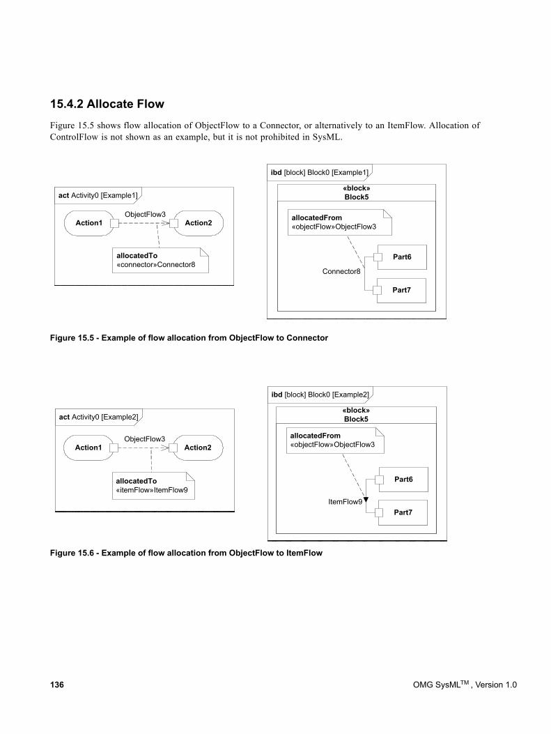
15.4.2 Allocate FlowFigure 15.5 shows flow allocation of ObjectFlow to a Connector, or alternatively to an ItemFlow. Allocation of ControlFlow is not shown as an example, but it is not prohibited in SysML.
Figure 15.5 - Example of flow allocation from ObjectFlow to Connector
Figure 15.6 - Example of flow allocation from ObjectFlow to ItemFlow
ibd [block] Block0 [Example1]
act Activity0 [Example1]«block»Block5
Part6
Part7
allocatedFrom«objectFlow»ObjectFlow3
ObjectFlow3Action1 Action2
allocatedTo«connector»Connector8
Connector8
ibd [block] Block0 [Example2]
act Activity0 [Example2]
ObjectFlow3Action1 Action2
«block»Block5
Part6
Part7
allocatedTo«itemFlow»ItemFlow9
allocatedFrom«objectFlow»ObjectFlow3
ItemFlow9
136 OMG SysMLTM , Version 1.0
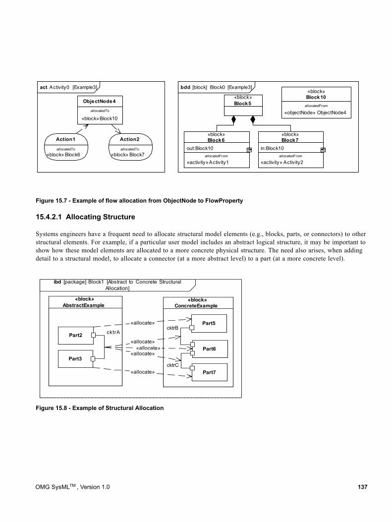
Figure 15.7 - Example of flow allocation from ObjectNode to FlowProperty
15.4.2.1 Allocating Structure
Systems engineers have a frequent need to allocate structural model elements (e.g., blocks, parts, or connectors) to other structural elements. For example, if a particular user model includes an abstract logical structure, it may be important to show how these model elements are allocated to a more concrete physical structure. The need also arises, when adding detail to a structural model, to allocate a connector (at a more abstract level) to a part (at a more concrete level).
Figure 15.8 - Example of Structural Allocation
bdd [block] Block0 [Example3]act Activity0 [Example3]
«block» Block6
Action1
«block»Block10
ObjectNode4«block»Block5
«objectNode» ObjectNode4
«block»Block10
«activity»Activity1
out:Block10
«block»Block6
«activity» Activity2
in:Block10
«block»Block7
«block» Block7
Action2
allocatedFrom
allocatedFromallocatedFrom
allocatedTo allocatedTo
allocatedTo
ibd [package] Block1 [Abstract to Concrete StructuralAllocation]
«block»AbstractExample
Part2
Part3
«block»ConcreteExample
Part6
Part7
Part5
cktrAcktrB
cktrC
«allocate»
«allocate»
«allocate»«allocate»
«allocate»
OMG SysMLTM , Version 1.0 137
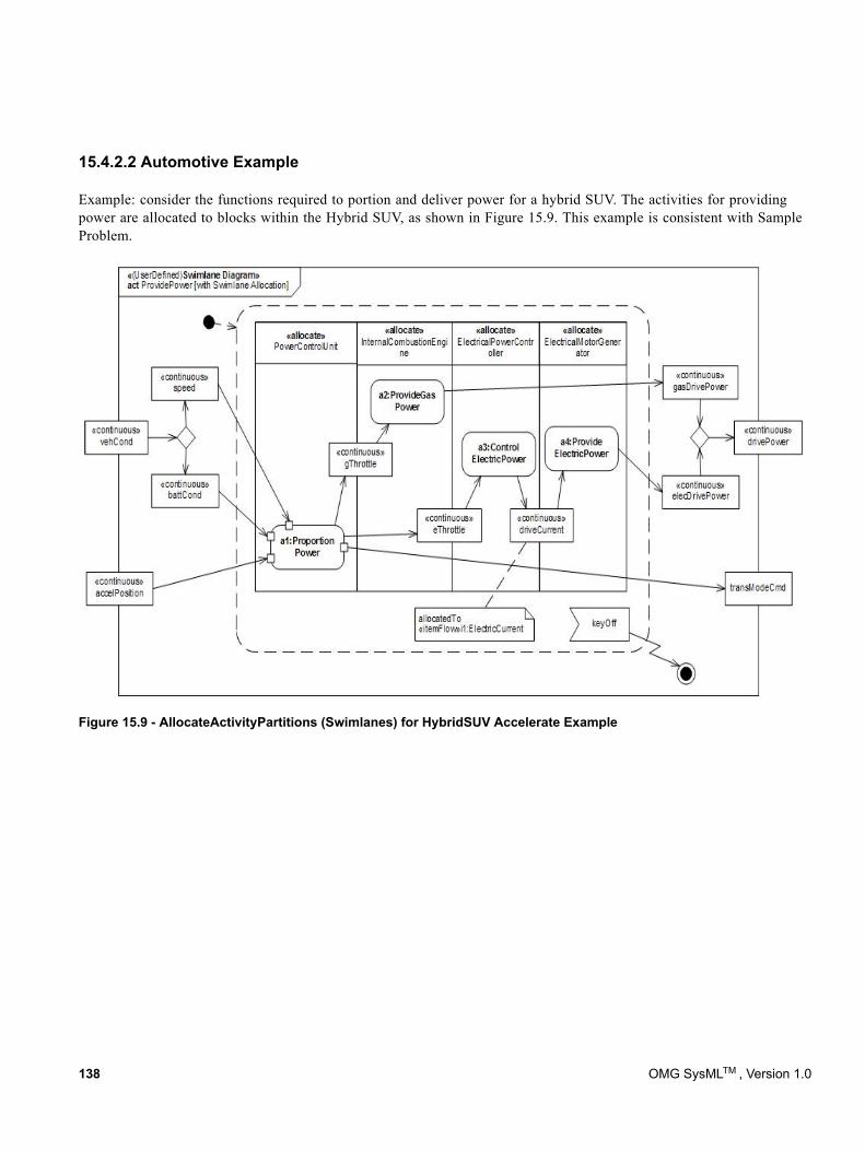
15.4.2.2 Automotive Example
Example: consider the functions required to portion and deliver power for a hybrid SUV. The activities for providing power are allocated to blocks within the Hybrid SUV, as shown in Figure 15.9. This example is consistent with Sample Problem.
Figure 15.9 - AllocateActivityPartitions (Swimlanes) for HybridSUV Accelerate Example
138 OMG SysMLTM , Version 1.0
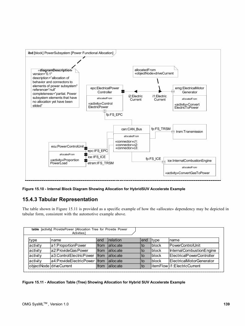
Figure 15.10 - Internal Block Diagram Showing Allocation for HybridSUV Accelerate Example
15.4.3 Tabular RepresentationThe table shown in Figure 15.11 is provided as a specific example of how the «allocate» dependency may be depicted in tabular form, consistent with the automotive example above.
Figure 15.11 - Allocation Table (Tree) Showing Allocation for Hybrid SUV Accelerate Example
ibd [block] PowerSubsystem [Power Functional Allocation]
allocatedFrom
«activity»ConvertElectricToPower
emg:ElectricalMotorGenerator
trsm:Transmission
allocatedFrom
«activity»ConvertGasToPower
ice:InternalCombustionEngine
allocatedFrom
«activity»ProportionPowerLoad
ecu:PowerControlUnitepc:IFS_EPC
fp:FS_ICE
allocatedFrom
«activity»ControlElectricPower
epc:ElectricalPowerController
i1:ElectricCurrent
i2:ElectricCurrent
fp:FS_EPC
fp:FS_TRSM
allocatedFrom«objectNode»driveCurrent
allocatedFrom
«connector»c1: «connector»c2: «connector»c3:
can:CAN_Bus
ice:IFS_ICE
etrsm:IFS_TRSM
<>
<>
<>
<>
<>
<>
<>
<>
«diagramDescription»version=”0.1"description=”allocation of behavior and connectors to elements of power subsystem"reference=”null”completeness=”partial. Power subsystem elements that have no allocation yet have been elided”
table [activity] ProvidePower [Allocation Tree for Provide PowerActivities]
type name end relation end type nameactivity a1:ProportionPower from allocate to block PowerControlUnitactivity a2:ProvideGasPower from allocate to block InternalCombustionEngineactivity a3:ControlElectricPower from allocate to block ElectricalPowerControlleractivity a4:ProvideElectricPower from allocate to block ElectricalMotorGeneratorobjectNode driveCurrent from allocate to itemFlow i1:ElectricCurrent
OMG SysMLTM , Version 1.0 139
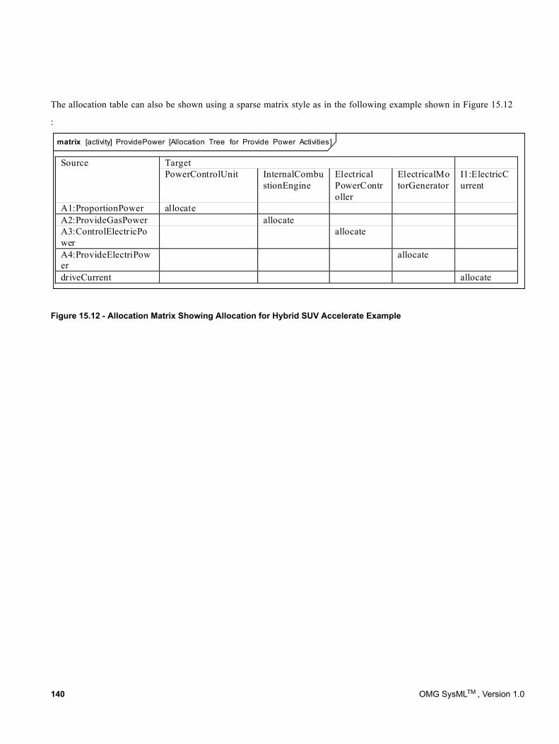
The allocation table can also be shown using a sparse matrix style as in the following example shown in Figure 15.12
:
Figure 15.12 - Allocation Matrix Showing Allocation for Hybrid SUV Accelerate Example
matrix [activity] ProvidePower [Allocation Tree for Provide Power Activities]
Source Target PowerControlUnit InternalCombu
stionEngine Electrical PowerController
ElectricalMotorGenerator
I1:ElectricCurrent
A1:ProportionPower allocate A2:ProvideGasPower allocate A3:ControlElectricPower
allocate
A4:ProvideElectriPower
allocate
driveCurrent allocate
140 OMG SysMLTM , Version 1.0
16 Requirements
16.1 Overview A requirement specifies a capability or condition that must (or should) be satisfied. A requirement may specify a function that a system must perform or a performance condition a system must achieve. SysML provides modeling constructs to represent text-based requirements and relate them to other modeling elements. The requirements diagram described in this chapter can depict the requirements in graphical, tabular, or tree structure format. A requirement can also appear on other diagrams to show its relationship to other modeling elements. The requirements modeling constructs are intended to provide a bridge between traditional requirements management tools and the other SysML models.
A requirement is defined as a stereotype of UML Class subject to a set of constraints. A standard requirement includes properties to specify its unique identifier and text requirement. Additional properties such as verification status, can be specified by the user.
Several requirements relationships are specified that enable the modeler to relate requirements to other requirements as well as to other model elements. These include relationships for defining a requirements hierarchy, deriving requirements, satisfying requirements, verifying requirements, and refining requirements.
A composite requirement can contain subrequirements in terms of a requirements hierarchy, specified using the UML namespace containment mechanism. This relationship enables a complex requirement to be decomposed into its containing child requirements. A composite requirement may state that the system shall do A and B and C, which can be decomposed into the child requirements that the system shall do A, the system shall do B, and the system shall do C. An entire specification can be decomposed into children requirements, which can be further decomposed into their children to define the requirements hierarchy.
There is a real need for requirement reuse across product families and projects. Typical scenarios are regulatory, statutory, or contractual requirements that are applicable across products and/or projects and requirements that are reused across product families (versions/variants). In these cases, one would like to be able to reference a requirement, or requirement set in multiple contexts with updates to the original requirements propagated to the reused requirement(s).
The use of namespace containment to specify requirements hierarchies precludes reusing requirements in different contexts since a given model element can only exist in one namespace. Since the concept of requirements reuse is very important in many applications, SysML introduces the concept of a slave requirement. A slave requirement is a requirement whose text property is a read-only copy of the text property of a master requirement. The text property of the slave requirement is constrained to be the same as the text property of the related master requirement. The master/slave relationship is indicated by the use of the copy relationship.
The “derive requirement” relationship relates a derived requirement to its source requirement. This typically involves analysis to determine the multiple derived requirements that support a source requirement. The derived requirements generally correspond to requirements at the next level of the system hierarchy. A simple example may be a vehicle acceleration requirement that is analyzed to derive requirements for engine power, vehicle weight, and body drag.
The satisfy relationship describes how a design or implementation model satisfies one or more requirements. A system modeler specifies the system design elements that are intended to satisfy the requirement. In the example above, the engine design satisfies the engine power requirement.
OMG SysMLTM , Version 1.0 141
The verify relationship defines how a test case or other model element verifies a requirement. In SysML, a test case or other named element can be used as a general mechanism to represent any of the standard verification methods for inspection, analysis, demonstration, or test. Additional subclasses can be defined by the user if required to represent the different verification methods. A verdict property of a test case can be used to represent the verification result. The SysML test case is defined consistent with the UML testing profile to facilitate integration between the two profiles.
The refine requirement relationship can be used to describe how a model element or set of elements can be used to further refine a requirement. For example, a use case or activity diagram may be used to refine a text-based functional requirement. Alternatively, it may be used to show how a text-based requirement refines a model element. In this case, some elaborated text could be used to refine a less fine-grained model element.
A generic trace requirement relationship provides a general-purpose relationship between a requirement and any other model element. The semantics of trace include no real constraints and therefore are quite weak. As a result, it is recommended that the trace relationship not be used in conjunction with the other requirements relationships described above.
The rationale construct that is defined in Chapter 7, “Model Elements” is quite useful in support of requirements. It enables the modeler to attach a rationale to any requirements relationship or to the requirement itself. For example, a rationale can be attached to a satisfy relationship that refers to an analysis report or trade study that provides the supporting rationale for why the particular design satisfies the requirement. Similarly, this can be used with the other relationships such as the derive relationship. It also provides an alternative mechanism to capture the verify relationship by attaching a rationale to a satisfy relationship that references a test case.
Modelers can customize requirements taxonomies by defining additional subclasses of the Requirement stereotype. For example, a modeler may want to define requirements categories to represent operational, functional, interface, performance, physical, storage, activation/deactivation, design constraints, and other specialized requirements such as reliability and maintainability, or to represent a high level stakeholder need. The stereotype enables the modeler to add constraints that restrict the types of model elements that may be assigned to satisfy the requirement. For example, a functional requirement may be constrained so that it can only be satisfied by a SysML behavior such as an activity, state machine, or interaction. Some potential Requirement subclasses are defined in Annex C: Non-normative Extensions.
142 OMG SysMLTM , Version 1.0
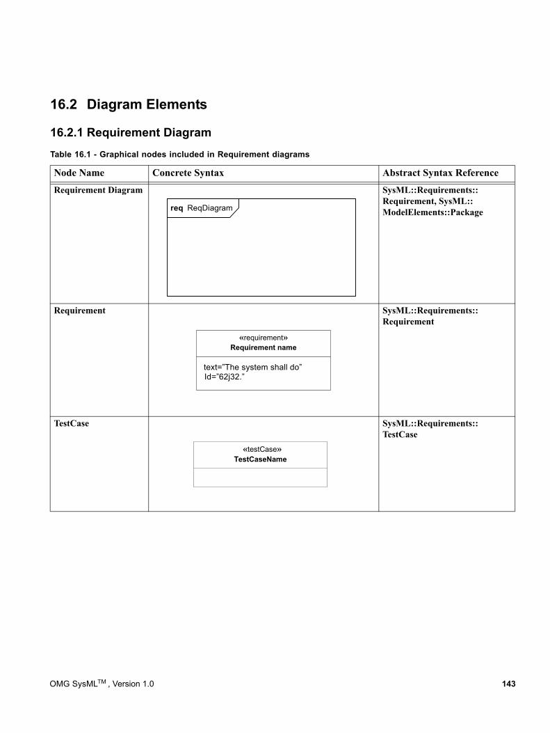
16.2 Diagram Elements
16.2.1 Requirement Diagram
Requirement Diagram SysML::Requirements:: Requirement, SysML:: ModelElements::Package
Requirement SysML::Requirements:: Requirement
TestCase SysML::Requirements:: TestCase
Table 16.1 - Graphical nodes included in Requirement diagrams
Node Name Concrete Syntax Abstract Syntax Reference
req ReqDiagram
«requirement»Requirement name
text=”The system shall do”Id=”62j32.”
«testCase»TestCaseName
OMG SysMLTM , Version 1.0 143
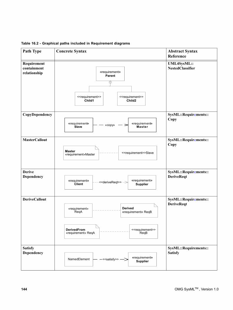
Table 16.2 - Graphical paths included in Requirement diagrams
Path Type Concrete Syntax Abstract Syntax Reference
Requirement containment relationship
UML4SysML:: NestedClassifier
CopyDependency SysML::Requirements:: Copy
MasterCallout
Master«requirement»Master <<requirement>>Slave
SysML::Requirements:: Copy
Derive Dependency
SysML::Requirements:: DeriveReqt
DeriveCallout
Derived«requirement» ReqB
«requirement»ReqA
DerivedFrom«requirement» ReqA
<<requirement>>ReqB
SysML::Requirements:: DeriveReqt
Satisfy Dependency
SysML::Requirements:: Satisfy
«requirement»Parent
<<requirement>>Child1
<<requirement>>Child2
«requirement»Slave
«requirement»Master«copy»
«requirement»Client
«requirement»Supplier<<deriveReqt>>
<<satisfy>> «requirement»SupplierNamedElement
144 OMG SysMLTM , Version 1.0
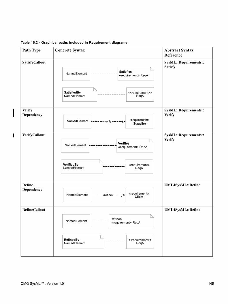
SatisfyCallout
Satisfies«requirement» ReqANamedElement
SatisfiedByNamedElement
<<requirement>>ReqA
SysML::Requirements:: Satisfy
Verify Dependency
SysML::Requirements:: Verify
VerifyCallout
Verifies«requirement» ReqANamedElement
VerifiedByNamedElement
«requirement»ReqA
SysML::Requirements:: Verify
Refine Dependency
UML4SysML::Refine
RefineCallout
Refines «requirement» ReqANamedElement
RefinedByNamedElement
<<requirement>>ReqA
UML4SysML::Refine
Table 16.2 - Graphical paths included in Requirement diagrams
Path Type Concrete Syntax Abstract Syntax Reference
«verify»NamedElement «requirement»Supplier
«refine» «requirement»ClientNamedElement
OMG SysMLTM , Version 1.0 145
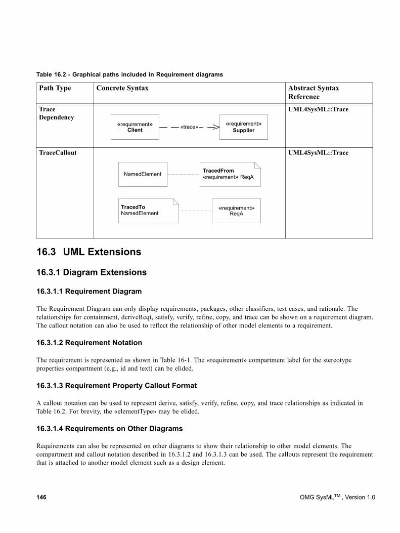
16.3 UML Extensions
16.3.1 Diagram Extensions
16.3.1.1 Requirement Diagram
The Requirement Diagram can only display requirements, packages, other classifiers, test cases, and rationale. The relationships for containment, deriveReqt, satisfy, verify, refine, copy, and trace can be shown on a requirement diagram. The callout notation can also be used to reflect the relationship of other model elements to a requirement.
16.3.1.2 Requirement Notation
The requirement is represented as shown in Table 16-1. The «requirement» compartment label for the stereotype properties compartment (e.g., id and text) can be elided.
16.3.1.3 Requirement Property Callout Format
A callout notation can be used to represent derive, satisfy, verify, refine, copy, and trace relationships as indicated in Table 16.2. For brevity, the «elementType» may be elided.
16.3.1.4 Requirements on Other Diagrams
Requirements can also be represented on other diagrams to show their relationship to other model elements. The compartment and callout notation described in 16.3.1.2 and 16.3.1.3 can be used. The callouts represent the requirement that is attached to another model element such as a design element.
Trace Dependency
UML4SysML::Trace
TraceCallout
TracedFrom«requirement» ReqANamedElement
TracedToNamedElement
«requirement»ReqA
UML4SysML::Trace
Table 16.2 - Graphical paths included in Requirement diagrams
Path Type Concrete Syntax Abstract Syntax Reference
«trace»«requirement»Client
«requirement»Supplier
146 OMG SysMLTM , Version 1.0
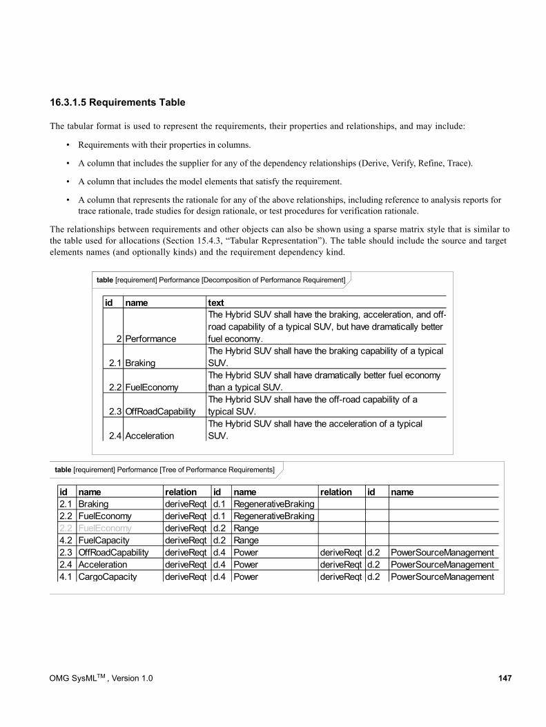
16.3.1.5 Requirements Table
The tabular format is used to represent the requirements, their properties and relationships, and may include:
• Requirements with their properties in columns.
• A column that includes the supplier for any of the dependency relationships (Derive, Verify, Refine, Trace).
• A column that includes the model elements that satisfy the requirement.
• A column that represents the rationale for any of the above relationships, including reference to analysis reports for trace rationale, trade studies for design rationale, or test procedures for verification rationale.
The relationships between requirements and other objects can also be shown using a sparse matrix style that is similar to the table used for allocations (Section 15.4.3, “Tabular Representation”). The table should include the source and target elements names (and optionally kinds) and the requirement dependency kind.
table [requirement] Performance [Tree of Performance Requirements]
table [requirement] Performance [Decomposition of Performance Requirement]
id name text
2 Performance
The Hybrid SUV shall have the braking, acceleration, and off-road capability of a typical SUV, but have dramatically better fuel economy.
2.1 BrakingThe Hybrid SUV shall have the braking capability of a typical SUV.
2.2 FuelEconomyThe Hybrid SUV shall have dramatically better fuel economy than a typical SUV.
2.3 OffRoadCapabilityThe Hybrid SUV shall have the off-road capability of a typical SUV.
2.4 AccelerationThe Hybrid SUV shall have the acceleration of a typical SUV.
id name relation id name relation id name2.1 Braking deriveReqt d.1 RegenerativeBraking2.2 FuelEconomy deriveReqt d.1 RegenerativeBraking2.2 FuelEconomy deriveReqt d.2 Range4.2 FuelCapacity deriveReqt d.2 Range2.3 OffRoadCapability deriveReqt d.4 Power deriveReqt d.2 PowerSourceManagement2.4 Acceleration deriveReqt d.4 Power deriveReqt d.2 PowerSourceManagement4.1 CargoCapacity deriveReqt d.4 Power deriveReqt d.2 PowerSourceManagement
OMG SysMLTM , Version 1.0 147
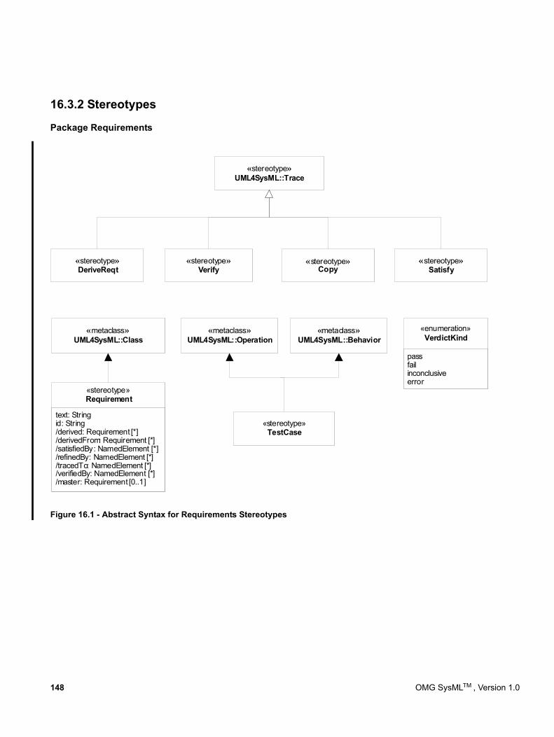
16.3.2 Stereotypes
Package Requirements
Figure 16.1 - Abstract Syntax for Requirements Stereotypes
«stereotype»TestCase
«metaclass»UML4SysML::Operation
«metaclass»UML4SysML::Behavior
«metaclass»UML4SysML::Class
text: Stringid: String/derived: Requirement [*]/derivedFrom: Requirement [*]/satisfiedBy: NamedElement [*]/refinedBy: NamedElement [*]/tracedTo: NamedElement [*]/verifiedBy: NamedElement [*]/master: Requirement [0..1]
«stereotype»Requirement
passfailinconclusiveerror
«enumeration»VerdictKind
«stereotype»UML4SysML::Trace
«stereotype»DeriveReqt
«stereotype»Verify
«stereotype»Satisfy
«stereotype»Copy
148 OMG SysMLTM , Version 1.0
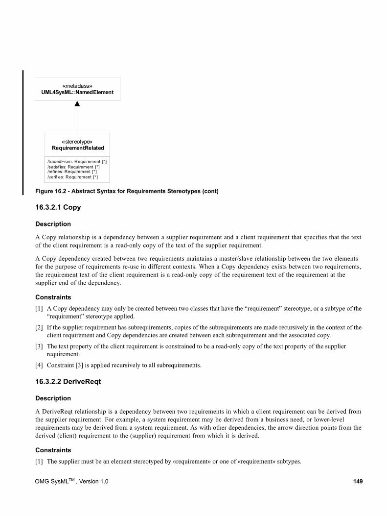
Figure 16.2 - Abstract Syntax for Requirements Stereotypes (cont)
16.3.2.1 Copy
Description
A Copy relationship is a dependency between a supplier requirement and a client requirement that specifies that the text of the client requirement is a read-only copy of the text of the supplier requirement.
A Copy dependency created between two requirements maintains a master/slave relationship between the two elements for the purpose of requirements re-use in different contexts. When a Copy dependency exists between two requirements, the requirement text of the client requirement is a read-only copy of the requirement text of the requirement at the supplier end of the dependency.
Constraints[1] A Copy dependency may only be created between two classes that have the “requirement” stereotype, or a subtype of the
“requirement” stereotype applied.
[2] If the supplier requirement has subrequirements, copies of the subrequirements are made recursively in the context of the client requirement and Copy dependencies are created between each subrequirement and the associated copy.
[3] The text property of the client requirement is constrained to be a read-only copy of the text property of the supplier requirement.
[4] Constraint [3] is applied recursively to all subrequirements.
16.3.2.2 DeriveReqt
Description
A DeriveReqt relationship is a dependency between two requirements in which a client requirement can be derived from the supplier requirement. For example, a system requirement may be derived from a business need, or lower-level requirements may be derived from a system requirement. As with other dependencies, the arrow direction points from the derived (client) requirement to the (supplier) requirement from which it is derived.
Constraints[1] The supplier must be an element stereotyped by «requirement» or one of «requirement» subtypes.
/tracedFrom: Requirement [* ]/satisf ies: Requirement [*]/refines: Requirement [* ]/verif ies: Requirement [* ]
«stereotype»RequirementRelated
«metaclass»UML4SysML::NamedElement
OMG SysMLTM , Version 1.0 149
[2] The client must be an element stereotyped by «requirement» or one of «requirement» subtypes.
16.3.2.3 Requirement
Description
A requirement specifies a capability or condition that must (or should) be satisfied.. A requirement may specify a function that a system must perform or a performance condition that a system must satisfy. Requirements are used to establish a contract between the customer (or other stakeholder) and those responsible for designing and implementing the system.
A requirement is a stereotype of Class. Compound requirements can be created by using the nesting capability of the class definition mechanism. The default interpretation of a compound requirement, unless stated differently by the compound requirement itself, is that all its subrequirements must be satisfied for the compound requirement to be satisfied. Subrequirements can be accessed through the “nestedClassifier” property of a class. When a requirement has nested requirements, all the nested requirements apply as part of the container requirement. Deleting the container requirement deleted the nested requirements, a functionality inherited from UML.
Attributes
• text: String The textual representation or a reference to the textual representation of the requirement.
• id: String The unique id of the requirement.
• /satisfiedBy: NamedElement [*] Derived from all elements that are the client of a «satisfy» relationship for which this requirement is a supplier.
• /verifiedBy: NamedElement [*] Derived from all elements that are the client of a «verify» relationship for which this requirement is a supplier.
• /tracedTo: NamedElement [*] Derived from all elements that are the client of a «trace» relationship for which this requirement is a supplier.
• /derived: Requirement [0..1] Derived from all requirements that are the client of a «deriveReqt» relationship for which this requirement is a supplier.
• /derivedFrom: Requirement [*] Derived from all requirements that are the supplier of a «deriveReqt» relationship for which this requirement is a client.
• /refinedBy: NamedElement [*] Derived from all elements that are the client of a «refine» relationship for which this requirement is a supplier.
• /master: Requirement [0..1 This is a derived property that lists the master requirement for this slave requirement. The master attribute is derived from the supplier of the Copy dependency that has this requirement as the slave.
Constraints[1] The property “ownedOperation” must be empty.
[2] The property “ownedAttribute” must be empty.
[3] Classes stereotyped by «requirement» may not participate in associations.
150 OMG SysMLTM , Version 1.0
[4] Classes stereotyped by «requirement» may not participate in generalizations.
[5] A nested classifier of a class stereotyped by «requirement» must also be stereotyped by «requirement».
16.3.2.4 RequirementRelated
Description
This stereotype is used to add properties to those elements that are related to requirements via the various dependencies described in Figure 16.1. The property values are shown using callout notation (i.e., notes) as shown in the diagram element table.
Attributes
• /tracedFrom: Requirement [*] Derived from all requirements that are the supplier of a «trace» relationship for which this element is a client.
• /satisfies: Requirement [*] Derived from all requirements that are the supplier of a «satisfy» relationship for which this element is a client.
• /refines: Requirement [*] Derived from all requirements that are the supplier of a «refine» relationship for which this element is a client.
• /verifies: Requirement [*] Derived from all requirements that are the supplier of a «verify» relationship for which this element is a client.
16.3.2.5 TestCase
Description
A test case is a method for verifying a requirement is satisfied.
Constraints[1] The type of return parameter of the stereotyped model element must be VerdictKind. (note this is consistent with the UML
Testing Profile).
16.3.2.6 Satisfy
Description
A Satisfy relationship is a dependency between a requirement and a model element that fulfills the requirement. As with other dependencies, the arrow direction points from the satisfying (client) model element to the (supplier) requirement that is satisfied.
Constraints[1] The supplier must be an element stereotyped by «requirement» or one of «requirement» subtypes.
OMG SysMLTM , Version 1.0 151
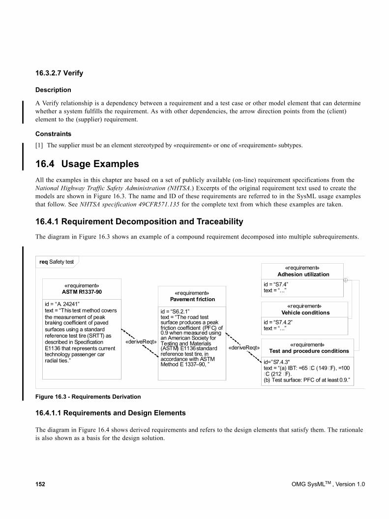
16.3.2.7 Verify
Description
A Verify relationship is a dependency between a requirement and a test case or other model element that can determine whether a system fulfills the requirement. As with other dependencies, the arrow direction points from the (client) element to the (supplier) requirement.
Constraints[1] The supplier must be an element stereotyped by «requirement» or one of «requirement» subtypes.
16.4 Usage ExamplesAll the examples in this chapter are based on a set of publicly available (on-line) requirement specifications from the National Highway Traffic Safety Administration (NHTSA.) Excerpts of the original requirement text used to create the models are shown in Figure 16.3. The name and ID of these requirements are referred to in the SysML usage examples that follow. See NHTSA specification 49CFR571.135 for the complete text from which these examples are taken.
16.4.1 Requirement Decomposition and TraceabilityThe diagram in Figure 16.3 shows an example of a compound requirement decomposed into multiple subrequirements.
Figure 16.3 - Requirements Derivation
16.4.1.1 Requirements and Design Elements
The diagram in Figure 16.4 shows derived requirements and refers to the design elements that satisfy them. The rationale is also shown as a basis for the design solution.
id = “A. 24241”text = “This test method covers the measurement of peak braking coefficient of paved surfaces using a standard reference test tire (SRTT) as described in Specification E1136 that represents current technology passenger car radial ties.”
«requirement»ASTM R1337-90
id = “S6.2.1”text = “The road test surface produces a peak friction coefficient (PFC) of 0.9 when measured using an American Society for Testing and Materials (ASTM) E1136 standard reference test tire, in accordance with ASTM Method E 1337–90, ”
«requirement»Pavement friction
id = “S7.4”text = “...”
«requirement»Adhesion utilization
id = “S7.4.2”text = “...”
«requirement»Vehicle conditions
id=”S7.4.3"text = “(a) IBT: =65 C (149 F), =100 C (212 F).
(b) Test surface: PFC of at least 0.9.”
«requirement»Test and procedure conditions«deriveReqt»
«deriveReqt»
req Safety test
152 OMG SysMLTM , Version 1.0
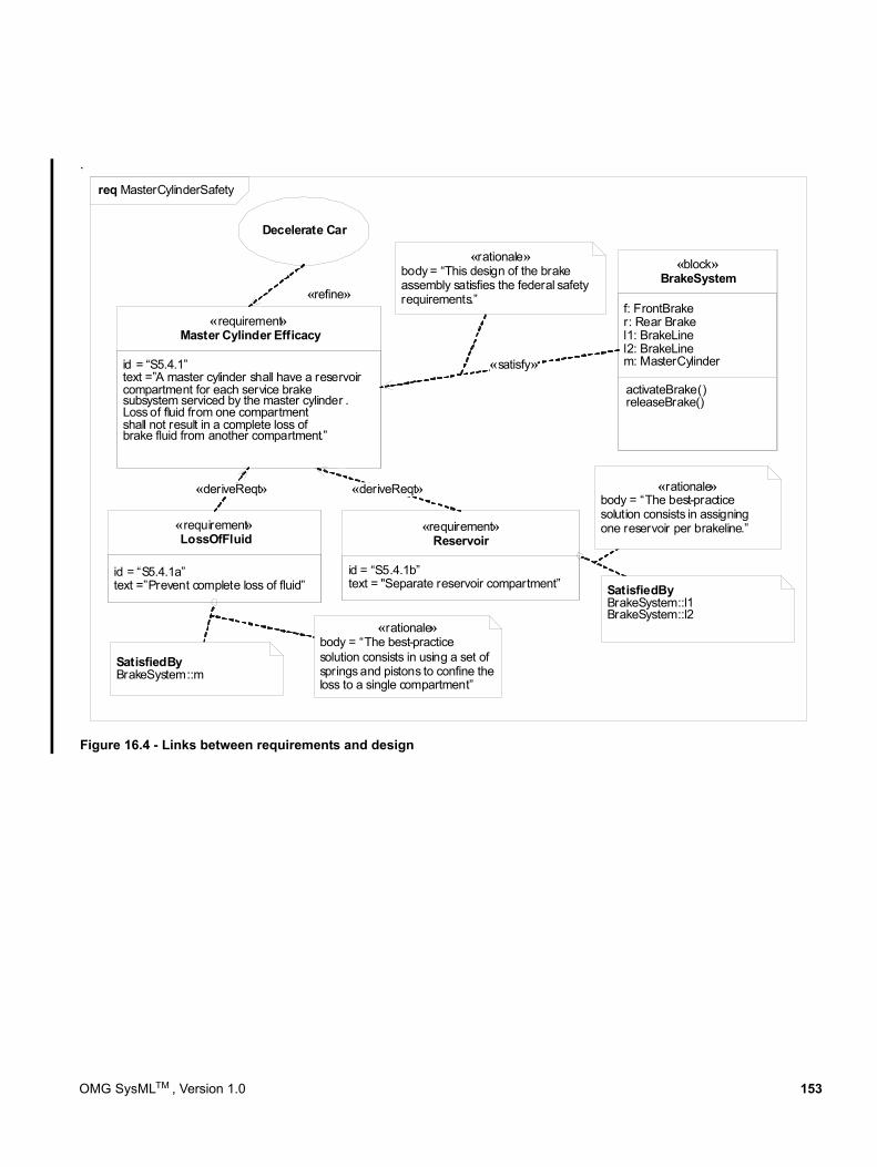
.
Figure 16.4 - Links between requirements and design
«requirement»Master Cylinder Efficacy
«requirement»LossOfFluid
«requirement»Reservoir
«block»BrakeSystem
«satisfy»
Decelerate Car
«refine»
«rationale»body = “This design of the brake assembly satisfies the federal safety requirements.”
id = “S5.4.1a”text =”Prevent complete loss of fluid”
id = “S5.4.1b”text = "Separate reservoir compartment”
id = “S5.4.1”text =”A master cylinder shall have a reservoircompartment for each service brakesubsystem serviced by the master cylinder .Loss of fluid from one compartmentshall not result in a complete loss of brake fluid from another compartment.”
«rationale»body = “The best-practice solution consists in using a set of springs and pistons to confine the loss to a single compartment”
«rationale»body = “The best-practice solution consists in assigning one reservoir per brakeline.”
«deriveReqt» «deriveReqt»
f: FrontBraker: Rear Brakel1: BrakeLinel2: BrakeLinem: MasterCylinder
activateBrake()releaseBrake()
SatisfiedByBrakeSystem::l1BrakeSystem::l2
SatisfiedByBrakeSystem::m
req MasterCylinderSafety
OMG SysMLTM , Version 1.0 153
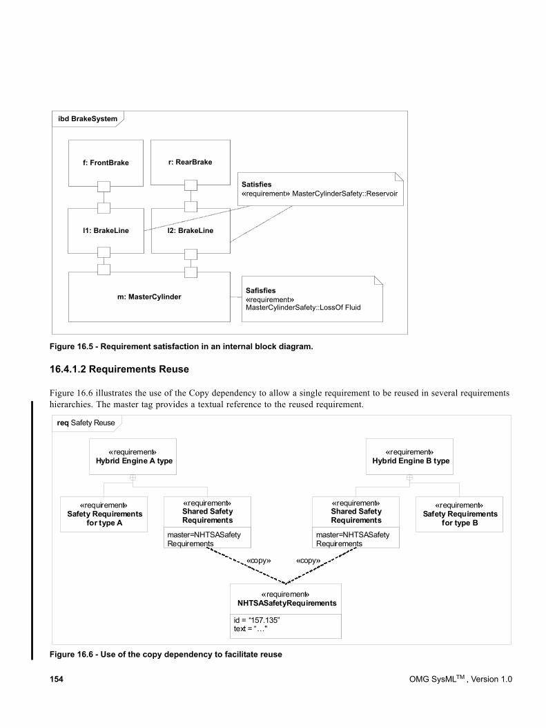
ibd BrakeSystem
m: MasterCylinder
l1: BrakeLine l2: BrakeLine
r: RearBrakef: FrontBrake
Safisfies«requirement»MasterCylinderSafety::LossOf Fluid
Satisfies«requirement» MasterCylinderSafety::Reservoir
Figure 16.5 - Requirement satisfaction in an internal block diagram.
16.4.1.2 Requirements Reuse
Figure 16.6 illustrates the use of the Copy dependency to allow a single requirement to be reused in several requirements hierarchies. The master tag provides a textual reference to the reused requirement.
Figure 16.6 - Use of the copy dependency to facilitate reuse
«requirement»NHTSASafetyRequirements
«requirement»Hybrid Engine A type
«requirement»Hybrid Engine B type
master=NHTSASafetyRequirements
«requirement»Shared Safety Requirements
master=NHTSASafetyRequirements
«requirement»Shared Safety Requirements
«requirement»Safety Requirements
for type A
«requirement»Safety Requirements
for type B
«copy» «copy»
id = “157.135”text = “…"
req Safety Reuse
154 OMG SysMLTM , Version 1.0
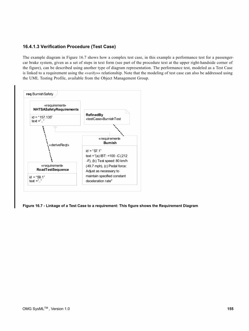
16.4.1.3 Verification Procedure (Test Case)
The example diagram in Figure 16.7 shows how a complex test case, in this example a performance test for a passenger-car brake system, given as a set of steps in text form (see part of the procedure text at the upper right-handside corner of the figure), can be described using another type of diagram representation. The performance test, modeled as a Test Case is linked to a requirement using the «verify»» relationship. Note that the modeling of test case can also be addressed using the UML Testing Profile, available from the Object Management Group.
Figure 16.7 - Linkage of a Test Case to a requirement: This figure shows the Requirement Diagram
«requirement»NHTSASafetyRequirements
«deriveReqt»
«requirement»RoadTestSequence
«requirement»Burnish
id = “157.135”text =”..”
id = “S9.1”text =”..”
RefinedBy«testCase»BurnishTest
id = “S7.1”text =”(a) IBT: =100 ¬C (212 ¬F), (b) Test speed: 80 km/h (49.7 mph), (c) Pedal force: Adjust as necessary to maintain specified constant deceleration rate"
req BurnishSafety
OMG SysMLTM , Version 1.0 155
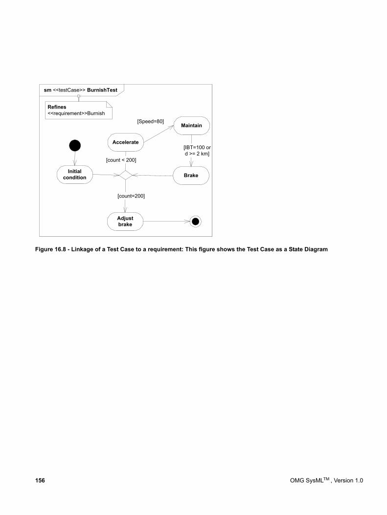
Figure 16.8 - Linkage of a Test Case to a requirement: This figure shows the Test Case as a State Diagram
[Speed=80]
Initialcondition
[count < 200]
[count=200]
Adjustbrake
Accelerate
Maintain
Brake
[IBT=100 ord >= 2 km]
sm <<testCase>> BurnishTest
Refines<<requirement>>Burnish
156 OMG SysMLTM , Version 1.0
17 Profiles & Model Libraries
17.1 OverviewThe Profiles package contains mechanisms that allow metaclasses from existing metamodels to be extended to adapt them for different purposes. This includes the ability to tailor the UML metamodel for different domains. The profiles mechanism is consistent with the OMG Meta Object Facility (MOF). SysML has added some notational extensions to represent stereotype properties in compartments as well as notes.
The stereotype is the primary mechanism used to create profiles to extend the metamodel. Stereotypes are defined by extending a metaclass, and then have them applied to the applicable model elements in the user model. A stereotype of a requirement could be extended to create a «functionalRequirement» as described in Annex C: Non-normative Extensions. This would allow specific properties and constraints to be created for a functional requirement. For example, a functional requirement may be constrained such that it must be satisfied by an operation or behavior. When the stereotype is applied to a requirement, then the requirement would include the notation «functionalRequirement» in addition to the name of the particular functional requirement. Extending the metaclass requirement is different from creating a subclass of requirement called functionalRequirement.
The Usage Examples section provides guidance both on how to use existing profiles and how to create new profiles. In addition, the examples provide guidance on the use of model libraries. A model library is a library of model elements including class and other type definitions that are considered reusable for a given domain. This guidelines can be applied to further customize SysML for domain specific applications such as automotive, military, or space systems.
OMG SysMLTM , Version 1.0 157
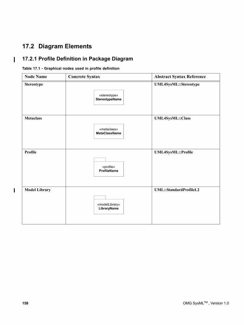
17.2 Diagram Elements
17.2.1 Profile Definition in Package Diagram
Stereotype UML4SysML::Stereotype
Metaclass
«metaclass»MetaClassName
UML4SysML::Class
Profile UML4SysML::Profile
Model Library UML::StandardProfileL2
Table 17.1 - Graphical nodes used in profile definition
Node Name Concrete Syntax Abstract Syntax Reference
«stereotype»StereotypeName
«profile»ProfileName
«modelLibrary»LibraryName
158 OMG SysMLTM , Version 1.0
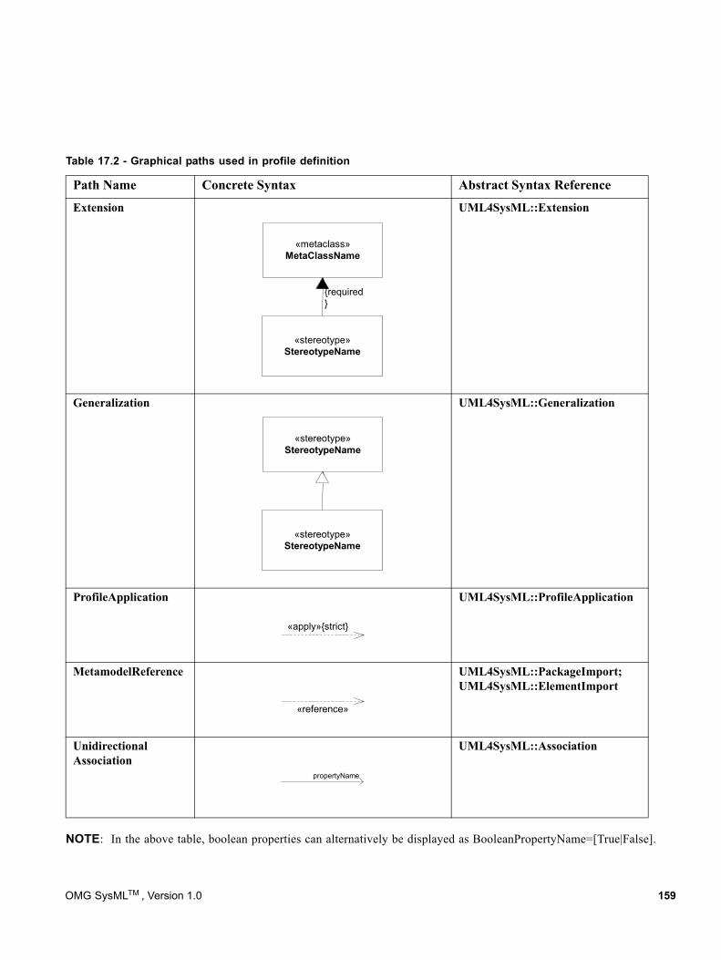
NOTE: In the above table, boolean properties can alternatively be displayed as BooleanPropertyName=[True|False].
Table 17.2 - Graphical paths used in profile definition
Path Name Concrete Syntax Abstract Syntax Reference
Extension UML4SysML::Extension
Generalization UML4SysML::Generalization
ProfileApplication UML4SysML::ProfileApplication
MetamodelReference UML4SysML::PackageImport; UML4SysML::ElementImport
Unidirectional Association
UML4SysML::Association
«metaclass»MetaClassName
«stereotype»StereotypeName
{required}
«stereotype»StereotypeName
«stereotype»StereotypeName
«apply»{strict}
«reference»
propertyName
OMG SysMLTM , Version 1.0 159
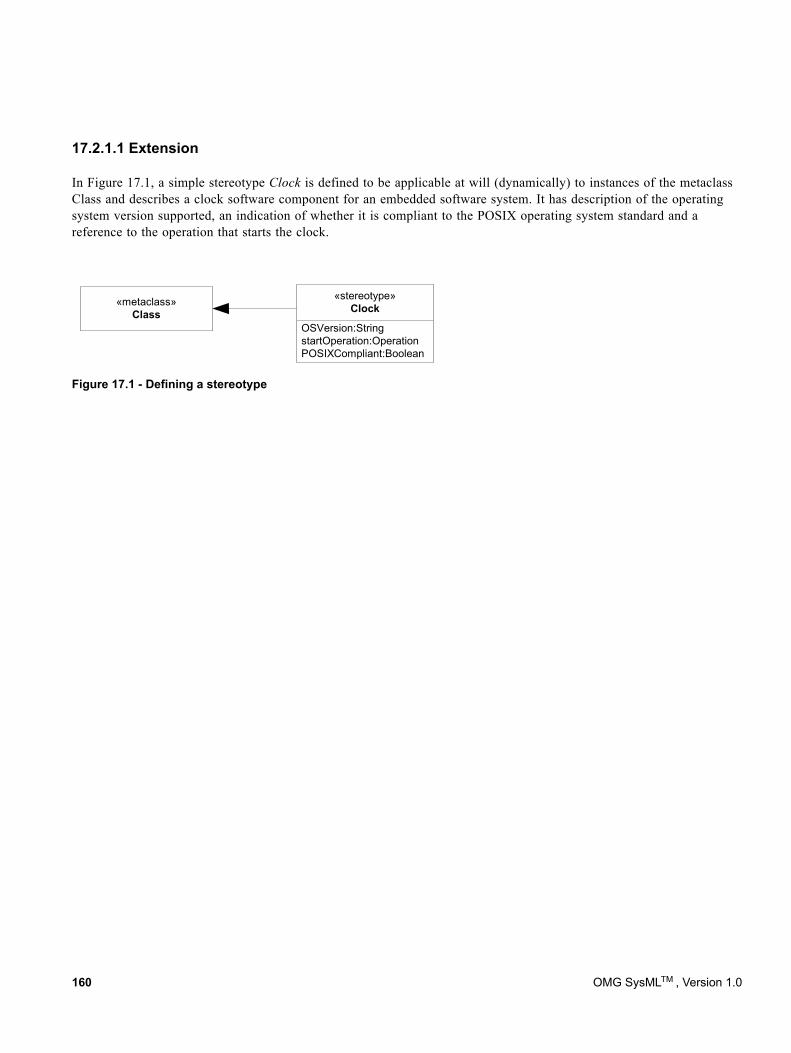
17.2.1.1 Extension
In Figure 17.1, a simple stereotype Clock is defined to be applicable at will (dynamically) to instances of the metaclass Class and describes a clock software component for an embedded software system. It has description of the operating system version supported, an indication of whether it is compliant to the POSIX operating system standard and a reference to the operation that starts the clock.
Figure 17.1 - Defining a stereotype
«stereotype»Clock
OSVersion:StringstartOperation:OperationPOSIXCompliant:Boolean
«metaclass»Class
160 OMG SysMLTM , Version 1.0
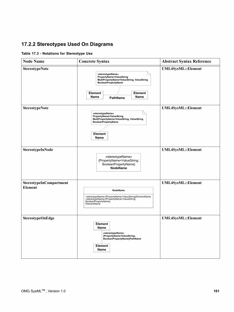
17.2.2 Stereotypes Used On DiagramsTable 17.3 - Notations for Stereotype Use
Node Name Concrete Syntax Abstract Syntax Reference
StereotypeNote UML4SysML::Element
StereotypeNote UML4SysML::Element
StereotypeInNode UML4SysML::Element
StereotypeInCompartment Element
UML4SysML::Element
StereotypeOnEdge UML4SysML::Element
ElementName
«stereotypeName»PropertyName=ValueStringMultiPropertyName=ValueString, ValueStringBooleanPropertyName
ElementNamePathName
ElementName
«stereotypeName»PropertyName=ValueStringMultiPropertyName=ValueString, ValueStringBooleanPropertyName
«stereotypeName»{PropertyName=ValueString;
BooleanPropertyName}NodeName
«stereotypeName»{PropertyName=ValueString}ElementName«stereotypeName»{PropertyName=ValueString;BooleanPropertyName}ElementName
NodeName
ElementName
ElementName
«stereotypeName»{PropertyName=ValueString;BooleanPropertyName}PathName
OMG SysMLTM , Version 1.0 161
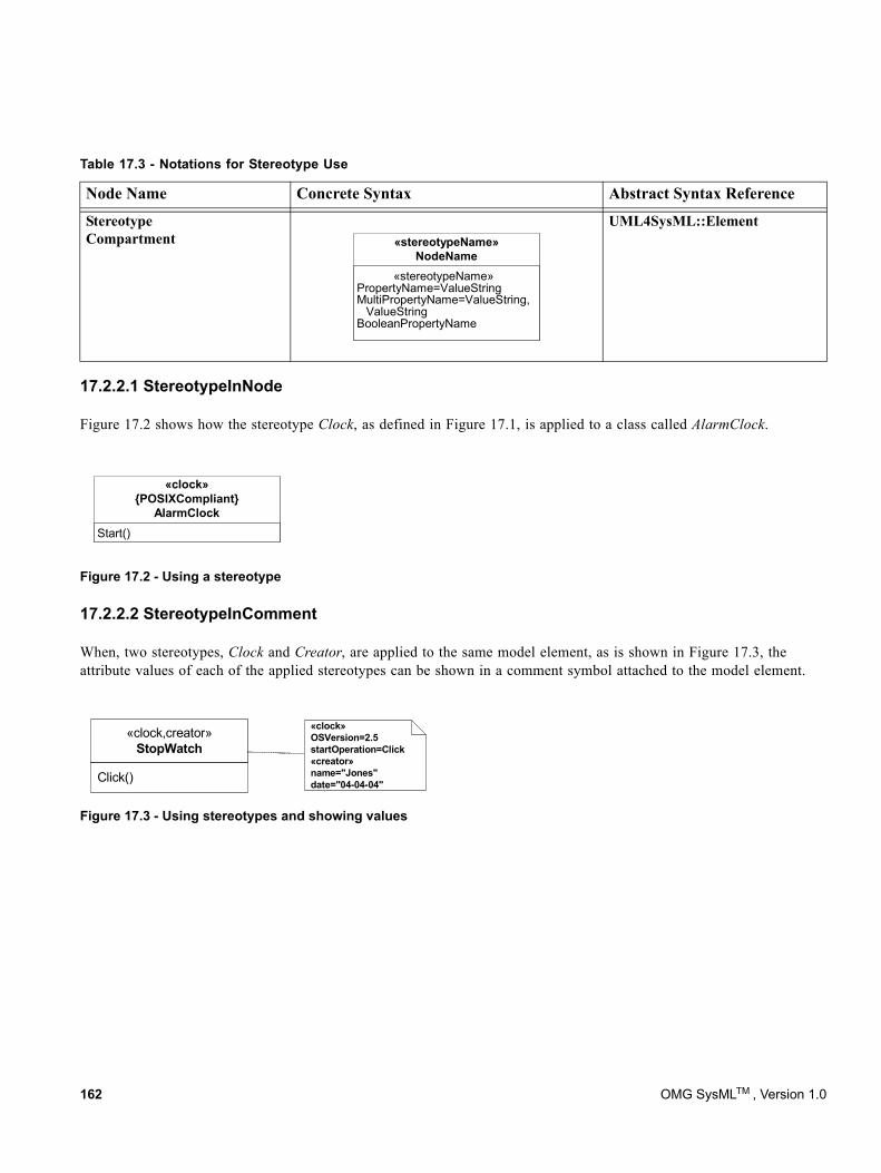
17.2.2.1 StereotypeInNode
Figure 17.2 shows how the stereotype Clock, as defined in Figure 17.1, is applied to a class called AlarmClock.
17.2.2.2 StereotypeInComment
When, two stereotypes, Clock and Creator, are applied to the same model element, as is shown in Figure 17.3, the attribute values of each of the applied stereotypes can be shown in a comment symbol attached to the model element.
Figure 17.3 - Using stereotypes and showing values
Stereotype Compartment
UML4SysML::Element
Figure 17.2 - Using a stereotype
Table 17.3 - Notations for Stereotype Use
Node Name Concrete Syntax Abstract Syntax Reference
«stereotypeName» PropertyName=ValueString MultiPropertyName=ValueString,
ValueString BooleanPropertyName
«stereotypeName»NodeName
Start()
«clock»{POSIXCompliant}
AlarmClock
«clock,creator»StopWatch
Click()
«clock»OSVersion=2.5startOperation=Click«creator»name="Jones"date="04-04-04"
162 OMG SysMLTM , Version 1.0
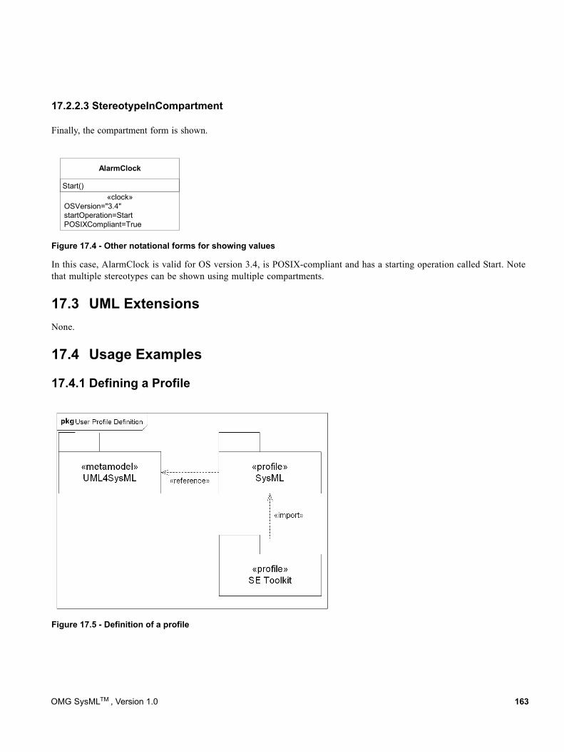
17.2.2.3 StereotypeInCompartment
Finally, the compartment form is shown.
Figure 17.4 - Other notational forms for showing values
In this case, AlarmClock is valid for OS version 3.4, is POSIX-compliant and has a starting operation called Start. Note that multiple stereotypes can be shown using multiple compartments.
17.3 UML ExtensionsNone.
17.4 Usage Examples
17.4.1 Defining a Profile
Figure 17.5 - Definition of a profile
Start()
AlarmClock
«clock»OSVersion="3.4"startOperation=StartPOSIXCompliant=True
OMG SysMLTM , Version 1.0 163
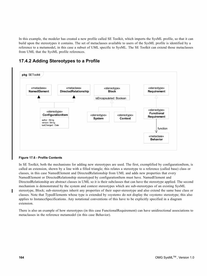
In this example, the modeler has created a new profile called SE Toolkit, which imports the SysML profile, so that it can build upon the stereotypes it contains. The set of metaclasses available to users of the SysML profile is identified by a reference to a metamodel, in this case a subset of UML specific to SysML. The SE Toolkit can extend those metaclasses from UML that the SysML profile references.
17.4.2 Adding Stereotypes to a Profile
Figure 17.6 - Profile Contents
In SE Toolkit, both the mechanisms for adding new stereotypes are used. The first, exemplified by configurationItem, is called an extension, shown by a line with a filled triangle; this relates a stereotype to a reference (called base) class or classes, in this case NamedElement and DirectedRelationship from UML and adds new properties that every NamedElement or DirectedRelationship stereotyped by configurationItem must have. NamedElement and DirectedRelationship are abstract classes in UML so it is their subclasses that can have the stereotype applied. The second mechanism is demonstrated by the system and context stereotypes which are sub-stereotypes of an existing SysML stereotype, Block; sub-stereotypes inherit any properties of their super-stereotype and also extend the same base class or classes. Note that TypedElements whose type is extended by «system» do not display the «system» stereotype; this also applies to InstanceSpecifications. Any notational conventions of this have to be explicitly specified in a diagram extension.
There is also an example of how stereotypes (in this case FunctionalRequirement) can have unidirectional associations to metaclasses in the reference metamodel (in this case Behavior).
«metaclass»NamedElement
isEncapsulated: Boolean
«stereotype»Block
«stereotype»System
«stereotype»Context
«stereotype»Requirement
«stereotype»Functional
Requirement
«metaclass»Behavior
function
«stereotype»ConfigurationItem
author : Stringversion: StringlastChanged : Date
«metaclass»DirectedRelationship
pkg SEToolkit
164 OMG SysMLTM , Version 1.0
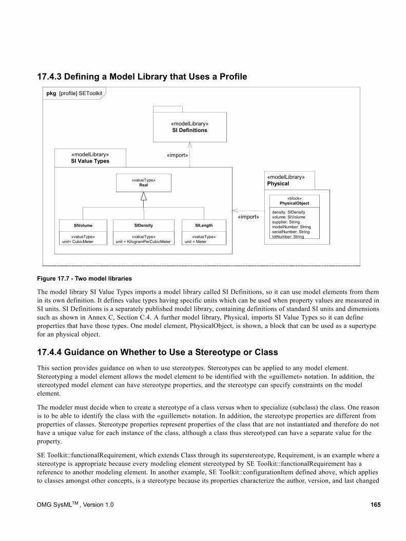
17.4.3 Defining a Model Library that Uses a Profile
pkg [profile] SEToolkit
«modelLibrary»SI Value Types
«valueType»unit = KilogramPerCubicMeter
SIDensity
«valueType»unit= CubicMeter
SIVolume
«valueType»Real
«modelLibrary»Physical
«valueType»unit = Meter
SILength
«import»density: SIDensityvolume: SIVolumesupplier: StringmodelNumber: StringserialNumber: StringlotNumber: String
«block»PhysicalObject
«modelLibrary»SI Definitions
«import»
Figure 17.7 - Two model libraries
The model library SI Value Types imports a model library called SI Definitions, so it can use model elements from them in its own definition. It defines value types having specific units which can be used when property values are measured in SI units. SI Definitions is a separately published model library, containing definitions of standard SI units and dimensions such as shown in Annex C, Section C.4. A further model library, Physical, imports SI Value Types so it can define properties that have those types. One model element, PhysicalObject, is shown, a block that can be used as a supertype for an physical object.
17.4.4 Guidance on Whether to Use a Stereotype or ClassThis section provides guidance on when to use stereotypes. Stereotypes can be applied to any model element. Stereotyping a model element allows the model element to be identified with the «guillemet» notation. In addition, the stereotyped model element can have stereotype properties, and the stereotype can specify constraints on the model element.
The modeler must decide when to create a stereotype of a class versus when to specialize (subclass) the class. One reason is to be able to identify the class with the «guillemet» notation. In addition, the stereotype properties are different from properties of classes. Stereotype properties represent properties of the class that are not instantiated and therefore do not have a unique value for each instance of the class, although a class thus stereotyped can have a separate value for the property.
SE Toolkit::functionalRequirement, which extends Class through its superstereotype, Requirement, is an example where a stereotype is appropriate because every modeling element stereotyped by SE Toolkit::functionalRequirement has a reference to another modeling element. In another example, SE Toolkit::configurationItem defined above, which applies to classes amongst other concepts, is a stereotype because its properties characterize the author, version, and last changed
OMG SysMLTM , Version 1.0 165
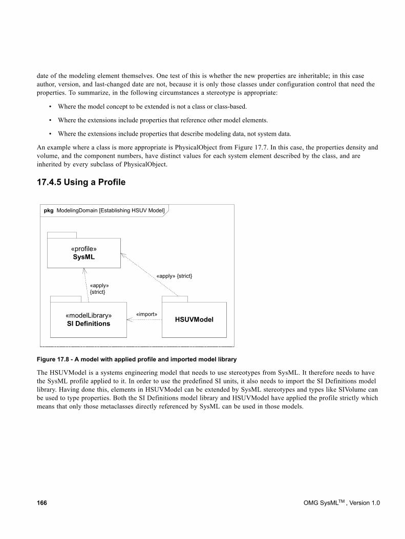
date of the modeling element themselves. One test of this is whether the new properties are inheritable; in this case author, version, and last-changed date are not, because it is only those classes under configuration control that need the properties. To summarize, in the following circumstances a stereotype is appropriate:
• Where the model concept to be extended is not a class or class-based.
• Where the extensions include properties that reference other model elements.
• Where the extensions include properties that describe modeling data, not system data.
An example where a class is more appropriate is PhysicalObject from Figure 17.7. In this case, the properties density and volume, and the component numbers, have distinct values for each system element described by the class, and are inherited by every subclass of PhysicalObject.
17.4.5 Using a Profile
Figure 17.8 - A model with applied profile and imported model library
The HSUVModel is a systems engineering model that needs to use stereotypes from SysML. It therefore needs to have the SysML profile applied to it. In order to use the predefined SI units, it also needs to import the SI Definitions model library. Having done this, elements in HSUVModel can be extended by SysML stereotypes and types like SIVolume can be used to type properties. Both the SI Definitions model library and HSUVModel have applied the profile strictly which means that only those metaclasses directly referenced by SysML can be used in those models.
pkg ModelingDomain [Establishing HSUV Model]
«modelLibrary»SI Definitions
«import»
«profile»SysML
HSUVModel
«apply»{strict}
«apply» {strict}
166 OMG SysMLTM , Version 1.0
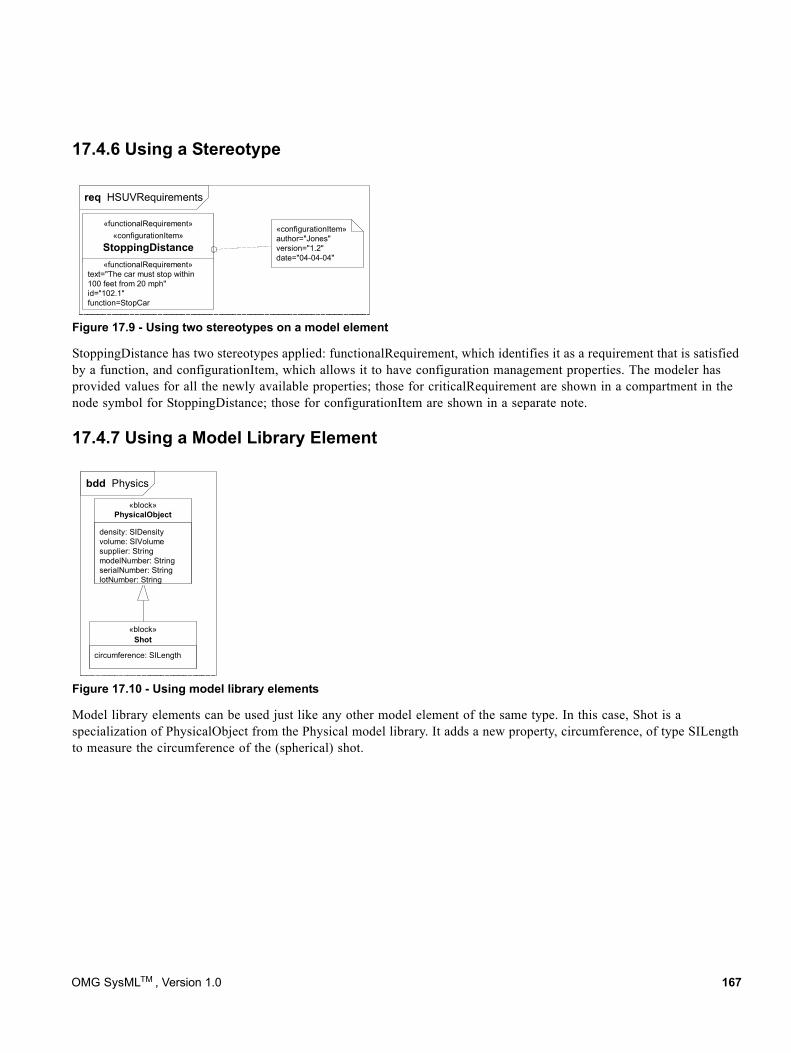
17.4.6 Using a Stereotype
req HSUVRequirements
«functionalRequirement»«configurationItem»
StoppingDistance«functionalRequirement»
text="The car must stop within100 feet from 20 mph"id="102.1"function=StopCar
«configurationItem»author="Jones"version="1.2"date="04-04-04"
Figure 17.9 - Using two stereotypes on a model element
StoppingDistance has two stereotypes applied: functionalRequirement, which identifies it as a requirement that is satisfied by a function, and configurationItem, which allows it to have configuration management properties. The modeler has provided values for all the newly available properties; those for criticalRequirement are shown in a compartment in the node symbol for StoppingDistance; those for configurationItem are shown in a separate note.
17.4.7 Using a Model Library Element
bdd Physics
circumference: SILength
«block»Shot
density: SIDensityvolume: SIVolumesupplier: StringmodelNumber: StringserialNumber: StringlotNumber: String
«block»PhysicalObject
Figure 17.10 - Using model library elements
Model library elements can be used just like any other model element of the same type. In this case, Shot is a specialization of PhysicalObject from the Physical model library. It adds a new property, circumference, of type SILength to measure the circumference of the (spherical) shot.
OMG SysMLTM , Version 1.0 167

168 OMG SysMLTM , Version 1.0
Part V - AnnexesThis section contains the following non-normative annexes for this specification.:
• A - Diagrams
• B - Sample Problem
• C - Non-normative Extensions
• D - Model Interchange
• E - Requirements Traceability
• F - Terms and Definitions
OMG SysMLTM , Version 1.0 169

170 OMG SysMLTM , Version 1.0
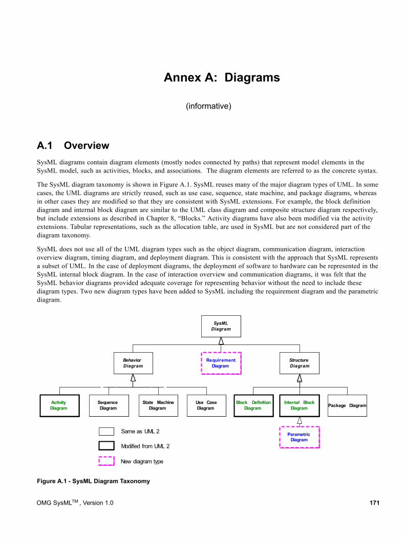
Annex A: Diagrams
(informative)
A.1 Overview
SysMLDiagram
StructureDiagram
BehaviorDiagram
Use CaseDiagram
ActivityDiagram
Internal BlockDiagram
Block DefinitionDiagram
SequenceDiagram
State MachineDiagram
ParametricDiagram
RequirementDiagram
Modified from UML 2
New diagram type
Package Diagram
Same as UML 2
SysML diagrams contain diagram elements (mostly nodes connected by paths) that represent model elements in the SysML model, such as activities, blocks, and associations. The diagram elements are referred to as the concrete syntax.
The SysML diagram taxonomy is shown in Figure A.1. SysML reuses many of the major diagram types of UML. In some cases, the UML diagrams are strictly reused, such as use case, sequence, state machine, and package diagrams, whereas in other cases they are modified so that they are consistent with SysML extensions. For example, the block definition diagram and internal block diagram are similar to the UML class diagram and composite structure diagram respectively, but include extensions as described in Chapter 8, “Blocks.” Activity diagrams have also been modified via the activity extensions. Tabular representations, such as the allocation table, are used in SysML but are not considered part of the diagram taxonomy.
SysML does not use all of the UML diagram types such as the object diagram, communication diagram, interaction overview diagram, timing diagram, and deployment diagram. This is consistent with the approach that SysML represents a subset of UML. In the case of deployment diagrams, the deployment of software to hardware can be represented in the SysML internal block diagram. In the case of interaction overview and communication diagrams, it was felt that the SysML behavior diagrams provided adequate coverage for representing behavior without the need to include these diagram types. Two new diagram types have been added to SysML including the requirement diagram and the parametric diagram.
Figure A.1 - SysML Diagram Taxonomy
OMG SysMLTM , Version 1.0 171
The requirement diagram is a new SysML diagram type. A requirement diagram provides a modeling construct for text-based requirements, and the relationship between requirements and other model elements that satisfy or verify them.
The parametric diagram is a new SysML diagram type that describes the constraints among the properties associated with blocks. This diagram is used to integrate behavior and structure models with engineering analysis models such as performance, reliability, and mass property models.
Although the taxonomy provides a logical organization for the various major kinds of diagrams, it does not preclude the careful mixing of different kinds of diagram types, as one might do when one combines structural and behavioral elements (e.g., showing a state machine nested inside a compartment of a block). However, it is critical that the types of diagram elements that can appear on a particular diagram kind be constrained and well-specified. The diagram elements tables in each chapter describe what symbols can appear in the diagram, but do not specify the different combinations of symbols that can be used.
The package diagram and the callout notation are two mechanisms that SysML provides for adding flexibility to represent a broad range of diagram elements on diagrams. The package diagram can be used quite flexibly to organize the model in packages and views. As such, a package diagram can include a wide array of packageable elements. The callout notation provides a mechanism for representing relationships between model elements that appear on different diagram kinds. In particular, they are used to represent allocations and requirements, such as the allocation of an activity to a block on a block definition diagram, or showing a part that satisfies a particular requirement on an internal block diagram. There are other mechanisms for representing this including the compartment notation that is generally described in Chapter 17, “Profiles & Model Libraries,” Chapter 16, “Requirements,” and Chapter 15, “Allocations” provide specific guidance on how these notations are used.
The model elements and corresponding concrete syntax that are represented in each of the nine SysML diagram kinds are described in the SysML chapters as indicated below.
• activity diagram - Activities chapter
• block definition diagram - Blocks chapter, Ports and Flows chapter
• internal block diagram - Blocks chapter, Ports and Flows chapter
• package diagram - Model Elements chapter
• parametric diagram - Constraint Blocks chapter
• requirement diagram - Requirements chapter
• state machine diagram - State Machines chapter
• sequence diagram - Interactions chapter
• use case diagram - Use Cases chapter
172 OMG SysMLTM , Version 1.0
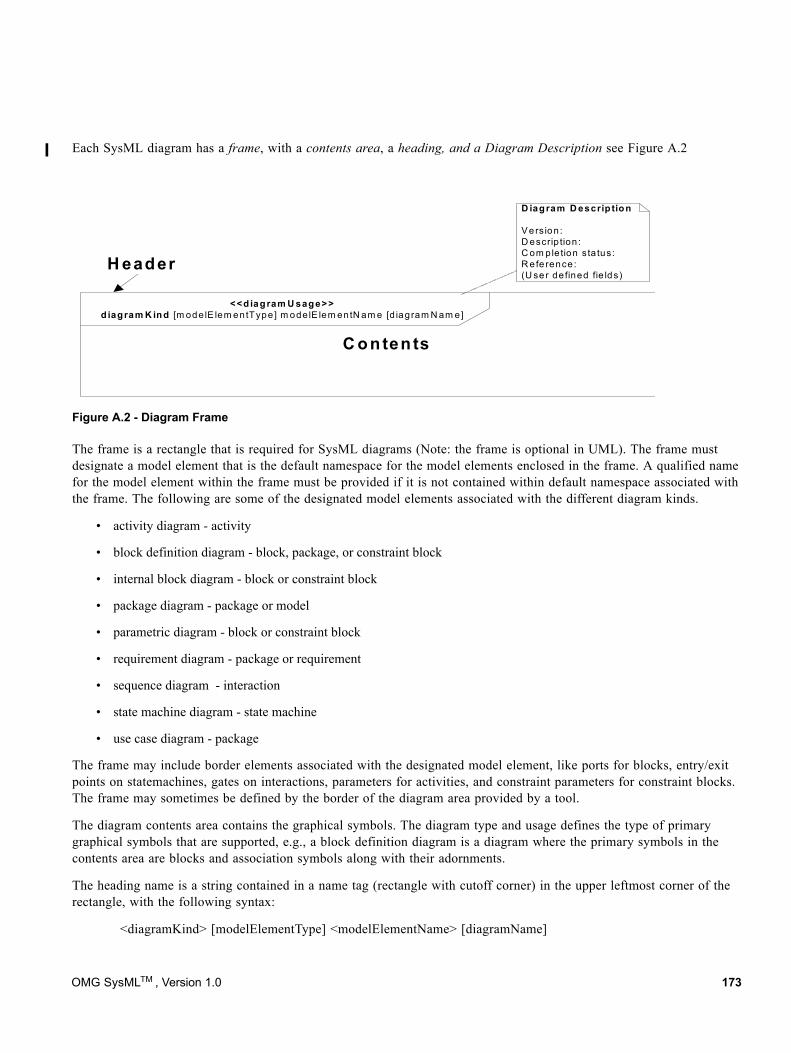
Each SysML diagram has a frame, with a contents area, a heading, and a Diagram Description see Figure A.2
The frame is a rectangle that is required for SysML diagrams (Note: the frame is optional in UML). The frame must designate a model element that is the default namespace for the model elements enclosed in the frame. A qualified name for the model element within the frame must be provided if it is not contained within default namespace associated with the frame. The following are some of the designated model elements associated with the different diagram kinds.
• activity diagram - activity
• block definition diagram - block, package, or constraint block
• internal block diagram - block or constraint block
• package diagram - package or model
• parametric diagram - block or constraint block
• requirement diagram - package or requirement
• sequence diagram - interaction
• state machine diagram - state machine
• use case diagram - package
The frame may include border elements associated with the designated model element, like ports for blocks, entry/exit points on statemachines, gates on interactions, parameters for activities, and constraint parameters for constraint blocks. The frame may sometimes be defined by the border of the diagram area provided by a tool.
The diagram contents area contains the graphical symbols. The diagram type and usage defines the type of primary graphical symbols that are supported, e.g., a block definition diagram is a diagram where the primary symbols in the contents area are blocks and association symbols along with their adornments.
The heading name is a string contained in a name tag (rectangle with cutoff corner) in the upper leftmost corner of the rectangle, with the following syntax:
<diagramKind> [modelElementType] <modelElementName> [diagramName]
Figure A.2 - Diagram Frame
C onten ts
<<diagram U sage>>d iagram K ind [m ode lE lem entType] m ode lE lem entN am e [d iagram N am e]
D iagram D escrip tion
V ers ion :D escrip tion :C om ple tion s ta tus:R efe rence :(U se r de fined fie lds)
H eader
OMG SysMLTM , Version 1.0 173
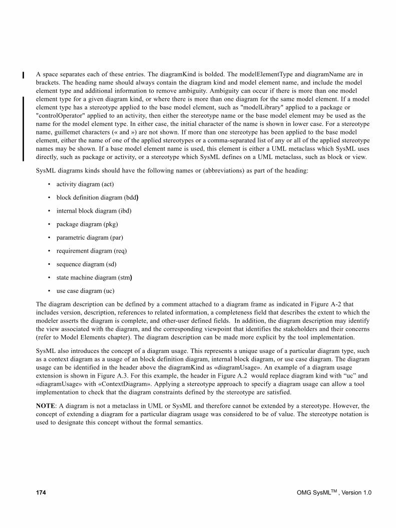
A space separates each of these entries. The diagramKind is bolded. The modelElementType and diagramName are in brackets. The heading name should always contain the diagram kind and model element name, and include the model element type and additional information to remove ambiguity. Ambiguity can occur if there is more than one model element type for a given diagram kind, or where there is more than one diagram for the same model element. If a model element type has a stereotype applied to the base model element, such as "modelLibrary" applied to a package or "controlOperator" applied to an activity, then either the stereotype name or the base model element may be used as the name for the model element type. In either case, the initial character of the name is shown in lower case. For a stereotype name, guillemet characters (« and ») are not shown. If more than one stereotype has been applied to the base model element, either the name of one of the applied stereotypes or a comma-separated list of any or all of the applied stereotype names may be shown. If a base model element name is used, this element is either a UML metaclass which SysML uses directly, such as package or activity, or a stereotype which SysML defines on a UML metaclass, such as block or view.
SysML diagrams kinds should have the following names or (abbreviations) as part of the heading:
• activity diagram (act)
• block definition diagram (bdd)
• internal block diagram (ibd)
• package diagram (pkg)
• parametric diagram (par)
• requirement diagram (req)
• sequence diagram (sd)
• state machine diagram (stm)
• use case diagram (uc)
The diagram description can be defined by a comment attached to a diagram frame as indicated in Figure A-2 that includes version, description, references to related information, a completeness field that describes the extent to which the modeler asserts the diagram is complete, and other-user defined fields. In addition, the diagram description may identify the view associated with the diagram, and the corresponding viewpoint that identifies the stakeholders and their concerns (refer to Model Elements chapter). The diagram description can be made more explicit by the tool implementation.
SysML also introduces the concept of a diagram usage. This represents a unique usage of a particular diagram type, such as a context diagram as a usage of an block definition diagram, internal block diagram, or use case diagram. The diagram usage can be identified in the header above the diagramKind as «diagramUsage». An example of a diagram usage extension is shown in Figure A.3. For this example, the header in Figure A.2 would replace diagram kind with “uc” and «diagramUsage» with «ContextDiagram». Applying a stereotype approach to specify a diagram usage can allow a tool implementation to check that the diagram constraints defined by the stereotype are satisfied.
NOTE: A diagram is not a metaclass in UML or SysML and therefore cannot be extended by a stereotype. However, the concept of extending a diagram for a particular diagram usage was considered to be of value. The stereotype notation is used to designate this concept without the formal semantics.
174 OMG SysMLTM , Version 1.0
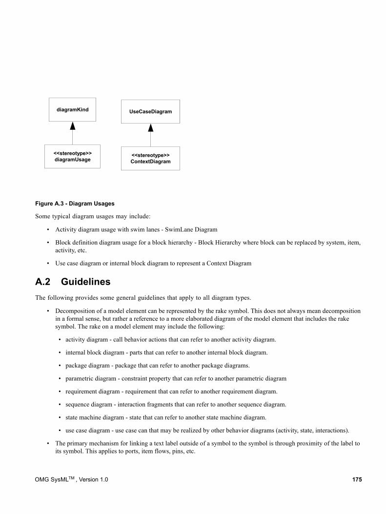
Figure A.3 - Diagram Usages
Some typical diagram usages may include:
• Activity diagram usage with swim lanes - SwimLane Diagram
• Block definition diagram usage for a block hierarchy - Block Hierarchy where block can be replaced by system, item, activity, etc.
• Use case diagram or internal block diagram to represent a Context Diagram
A.2 GuidelinesThe following provides some general guidelines that apply to all diagram types.
• Decomposition of a model element can be represented by the rake symbol. This does not always mean decomposition in a formal sense, but rather a reference to a more elaborated diagram of the model element that includes the rake symbol. The rake on a model element may include the following:
• activity diagram - call behavior actions that can refer to another activity diagram.
• internal block diagram - parts that can refer to another internal block diagram.
• package diagram - package that can refer to another package diagrams.
• parametric diagram - constraint property that can refer to another parametric diagram
• requirement diagram - requirement that can refer to another requirement diagram.
• sequence diagram - interaction fragments that can refer to another sequence diagram.
• state machine diagram - state that can refer to another state machine diagram.
• use case diagram - use case can that may be realized by other behavior diagrams (activity, state, interactions).
• The primary mechanism for linking a text label outside of a symbol to the symbol is through proximity of the label to its symbol. This applies to ports, item flows, pins, etc.
diagramKind
<<stereotype>>diagramUsage
UseCaseDiagram
<<stereotype>>ContextDiagram
OMG SysMLTM , Version 1.0 175
• Page connectors (on-page connectors and off-page connectors) can be used to reduce the clutter on diagrams, but should be used sparingly since they are equivalent to go-to’s in programming languages, and can lead to “spaghetti diagrams.” Whenever practical, elaborate the model element designated by the frame instead of using a page connector. A page connector is depicted as a circle with a label inside (often a letter). The circle is shown at both ends of a line break and means that the two line end connect at the circle.
• Diagram overlays are diagram elements that may be used on any diagram kind. An example of an overlay may be a geographic map to provide a spatial context for the symbols.
• SysML provides the capability to represent a document using the UML 2 standard stereotype «document» applied to the artifact model element. Properties of the artifact can capture information about the document. Use a «trace» abstraction to relate the document to model elements. The document can represent text that is contained in the related model elements.
• SysML diagrams including the enhancements described in this section is intended to conform to the Diagram Interchange Standard to facilitate exchange of diagram and layout information. A more formal BNF has been introduced in selected chapters to facilitate diagram interchange, which is referred to in the Language Formalism chapter.
• Tabular and matrix representation is an optional alternative notation that can be used in conjunction with the graphical symbols as long as the information is consistent with the underlying metamodel. Tabular and matrix representations are often used in systems engineering to represent detailed information and other views of the model such as interface definitions, requirements traceability, and allocation relationships between various types of model elements. They also can be convenient mechanisms to represent property values for selected properties, and basic relationships such as function and inputs/outputs in N2 charts. The UML superstructure contains a tabular representation of a sequence diagram in an interaction matrix (refer to Superstructure Annex with interaction matrix). The implementations of tabular and matrix representations are defined by the tool implementations and are not standardized in SysML at this time. However, tabular or matrix representations may be included in a frame with the heading designator «table» or «matrix» in bold.
• Graph and tree representations are also optional, alternative notations that can be used in conjunction with graphical symbols as long as the information is consistent with the underlying metamodel. These representations can be used for describing complex series of relationships that represent other views of the model. One example is the browser window in many tools that depicts a hierarchical view of the model. The implementations of graphs and trees are defined by the tool implementations and are not standardized in SysML at this time. However, graph and tree representations may be included in a frame with the heading designator «graph» or «tree» in bold.
176 OMG SysMLTM , Version 1.0
Annex B: Sample Problem
(informative)
B.1 PurposeThe purpose of this annex is to illustrate how SysML can support the specification, analysis, and design of a system using some of the basic features of the language.
B.2 ScopeThe scope of this example is to provide at least one diagram for each SysML diagram type. The intent is to select simplified fragments of the problem to illustrate how the diagrams can be applied, and also demonstrate some of the possible inter-relationships among the model elements in the different diagrams. The sample problem does not highlight all of the features of the language. The reader should refer to the individual chapters for more detailed features of the language. The diagrams selected for representing a particular aspect of the model, and the ordering of the diagrams are intended to be representative of applying a typical systems engineering process, but this will vary depending on the specific process and methodology that is used.
B.3 Problem SummaryThe sample problem describes the use of SysML as it applies to the development of an automobile, in particular a Hybrid gas/electric powered Sport Utility Vehicle (SUV). This problem is interesting in that it has inherently conflicting requirements, viz. desire for fuel efficiency, but also desire for large cargo carrying capacity and off-road capability. Technical accuracy and the feasibility of the actual solution proposed were not high priorities. This sample problem focuses on design decisions surrounding the power subsystem of the hybrid SUV; the requirements, performance analyses, structure, and behavior.
This annex is structured to show each diagram in the context of how it might be used on such a example problem. The first section shows SysML diagrams as they might be used to establish the system context; establishing system boundaries, and top level use cases. The next section is provided to show how SysML diagrams can be used to analyze top level system behavior, using sequence diagrams and state machine diagrams. The following section focuses on use of SysML diagrams for capturing and deriving requirements, using diagrams and tables. A section is provided to illustrate how SysML is used to depict system structure, including block hierarchy and part relationships. The relationship of various system parameters, performance constraints, analyses, and timing diagrams are illustrated in the next section. A section is then dedicated to illustrating definition and depiction of interfaces and flows in a structural context. The final section focuses on detailed behavior modeling, functional and flow allocation.
OMG SysMLTM, Version 1.0 177
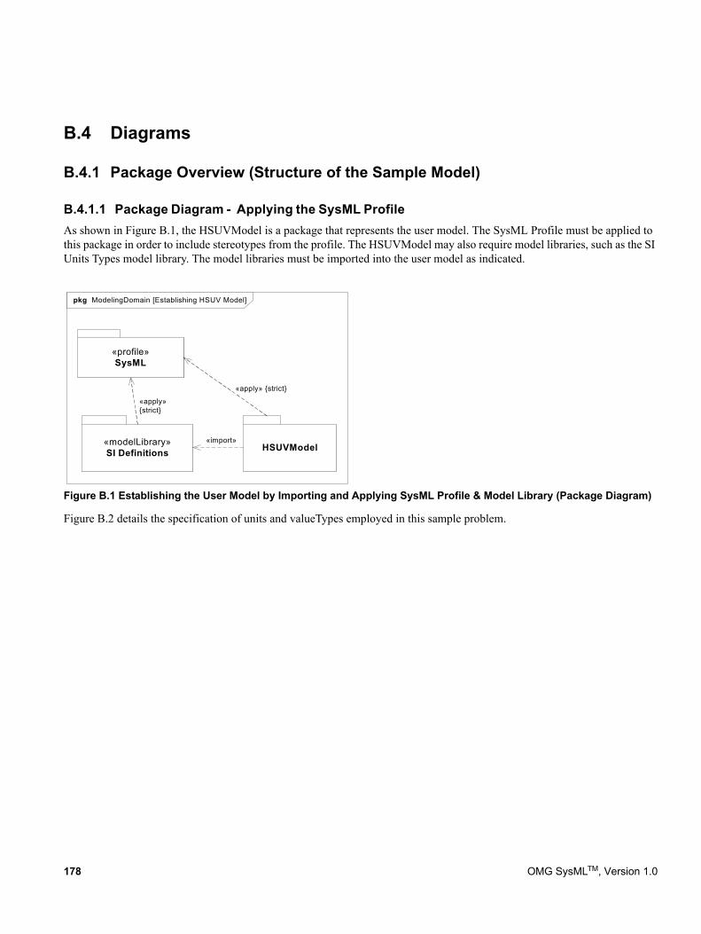
B.4 Diagrams
B.4.1 Package Overview (Structure of the Sample Model)
B.4.1.1 Package Diagram - Applying the SysML ProfileAs shown in Figure B.1, the HSUVModel is a package that represents the user model. The SysML Profile must be applied to this package in order to include stereotypes from the profile. The HSUVModel may also require model libraries, such as the SI Units Types model library. The model libraries must be imported into the user model as indicated.
Figure B.1 Establishing the User Model by Importing and Applying SysML Profile & Model Library (Package Diagram)
Figure B.2 details the specification of units and valueTypes employed in this sample problem.
pkg ModelingDomain [Establishing HSUV Model]
«modelLibrary»SI Definitions
«import»
«profile»SysML
HSUVModel
«apply»{strict}
«apply» {strict}
178 OMG SysMLTM, Version 1.0
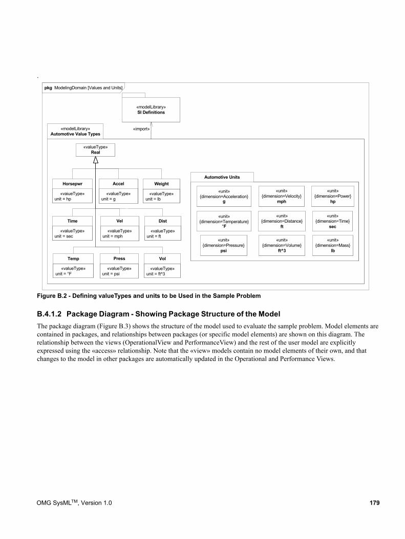
.
Figure B.2 - Defining valueTypes and units to be Used in the Sample Problem
B.4.1.2 Package Diagram - Showing Package Structure of the ModelThe package diagram (Figure B.3) shows the structure of the model used to evaluate the sample problem. Model elements are contained in packages, and relationships between packages (or specific model elements) are shown on this diagram. The relationship between the views (OperationalView and PerformanceView) and the rest of the user model are explicitly expressed using the «access» relationship. Note that the «view» models contain no model elements of their own, and that changes to the model in other packages are automatically updated in the Operational and Performance Views.
pkg ModelingDomain [Values and Units]
«modelLibrary»Automotive Value Types
Automotive Units
«modelLibrary»SI Definitions
«import»
«unit»{dimension=Power}
hp
«unit»{dimension=Temperature}
°F
«unit»{dimension=Acceleration}
g
«unit»{dimension=Mass}
lb
«unit»{dimension=Pressure}
psi
«unit»{dimension=Time}
sec
«unit»{dimension=Velocity}
mph
«unit»{dimension=Distance}
ft
«unit»{dimension=Volume}
ft^3
«valueType»unit = g
Accel
«valueType»unit = hp
Horsepwr
«valueType»Real
«valueType»unit = lb
Weight
«valueType»unit = mph
Vel
«valueType»unit = sec
Time
«valueType»unit = ft
Dist
«valueType»unit = psi
Press
«valueType»unit = °F
Temp
«valueType»unit = ft^3
Vol
OMG SysMLTM, Version 1.0 179
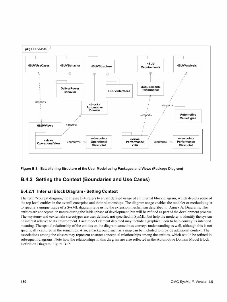
Figure B.3 - Establishing Structure of the User Model using Packages and Views (Package Diagram)
B.4.2 Setting the Context (Boundaries and Use Cases)
B.4.2.1 Internal Block Diagram - Setting Context The term “context diagram,” in Figure B.4, refers to a user defined usage of an internal block diagram, which depicts some of the top level entities in the overall enterprise and their relationships. The diagram usage enables the modeler or methodologist to specify a unique usage of a SysML diagram type using the extension mechanism described in Annex A: Diagrams. The entities are conceptual in nature during the initial phase of development, but will be refined as part of the development process. The «system» and «external» stereotypes are user defined, not specified in SysML, but help the modeler to identify the system of interest relative to its environment. Each model element depicted may include a graphical icon to help convey its intended meaning. The spatial relationship of the entities on the diagram sometimes conveys understanding as well, although this is not specifically captured in the semantics. Also, a background such as a map can be included to provide additional context. The associations among the classes may represent abstract conceptual relationships among the entities, which would be refined in subsequent diagrams. Note how the relationships in this diagram are also reflected in the Automotive Domain Model Block Definition Diagram, Figure B.15.
pkg HSUVModel
HSUVViews
HSUVRequirementsHSUVStructureHSUVBehavior
DeliverPowerBehavior
HSUVAnalysis
«view»Performance
View
«viewpoint»Performance
Viewpoint
«import»
«conform»
«block»Automotive
Domain
«view»OperationalView
«viewpoint»OperationalViewpoint
«conform»
«import»
«import»
HSUVUseCases
HSUVInterfaces«requirement»Performance
«import» AutomotiveValueTypes
180 OMG SysMLTM, Version 1.0
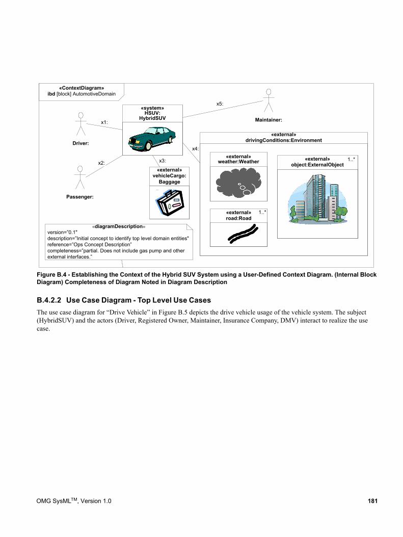
Figure B.4 - Establishing the Context of the Hybrid SUV System using a User-Defined Context Diagram. (Internal Block Diagram) Completeness of Diagram Noted in Diagram Description
B.4.2.2 Use Case Diagram - Top Level Use CasesThe use case diagram for “Drive Vehicle” in Figure B.5 depicts the drive vehicle usage of the vehicle system. The subject (HybridSUV) and the actors (Driver, Registered Owner, Maintainer, Insurance Company, DMV) interact to realize the use case.
«ContextDiagram»ibd [block] AutomotiveDomain
«external»drivingConditions:Environment
x1:
x4:
Maintainer:
x5:
«external»road:Road
«diagramDescription»version=”0.1"description=”Initial concept to identify top level domain entities"reference=”Ops Concept Description”completeness=”partial. Does not include gas pump and otherexternal interfaces.”
«external»object:ExternalObject
«system»HSUV:
HybridSUV
«external»weather:Weatherx2:
Driver:
Passenger:
1..*
1..*
«external»vehicleCargo:
Baggage
x3:
OMG SysMLTM, Version 1.0 181
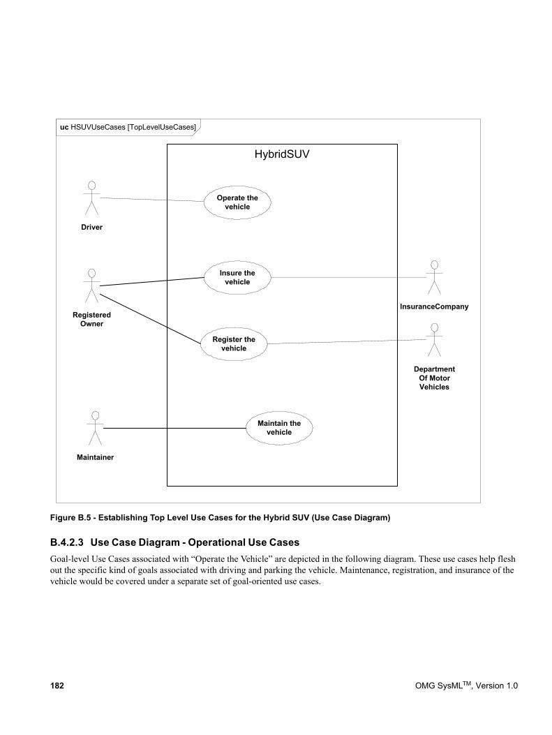
Figure B.5 - Establishing Top Level Use Cases for the Hybrid SUV (Use Case Diagram)
B.4.2.3 Use Case Diagram - Operational Use CasesGoal-level Use Cases associated with “Operate the Vehicle” are depicted in the following diagram. These use cases help flesh out the specific kind of goals associated with driving and parking the vehicle. Maintenance, registration, and insurance of the vehicle would be covered under a separate set of goal-oriented use cases.
uc HSUVUseCases [TopLevelUseCases]
HybridSUV
Driver
Operate thevehicle
Maintain thevehicle
Maintainer
Insure thevehicle
Register thevehicle
InsuranceCompany
DepartmentOf MotorVehicles
RegisteredOwner
182 OMG SysMLTM, Version 1.0
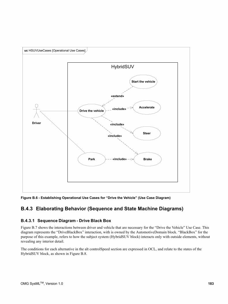
Figure B.6 - Establishing Operational Use Cases for “Drive the Vehicle” (Use Case Diagram)
B.4.3 Elaborating Behavior (Sequence and State Machine Diagrams)
B.4.3.1 Sequence Diagram - Drive Black BoxFigure B.7 shows the interactions between driver and vehicle that are necessary for the “Drive the Vehicle” Use Case. This diagram represents the “DriveBlackBox” interaction, with is owned by the AutomotiveDomain block. “BlackBox” for the purpose of this example, refers to how the subject system (HybridSUV block) interacts only with outside elements, without revealing any interior detail.
The conditions for each alternative in the alt controlSpeed section are expressed in OCL, and relate to the states of the HybridSUV block, as shown in Figure B.8.
uc HSUVUseCases [Operational Use Cases]
HybridSUV
Driver
AccelerateDrive the vehicle
Steer
Brake
«include»
«include»
«include»
Park «include»
«extend»
Start the vehicle
OMG SysMLTM, Version 1.0 183
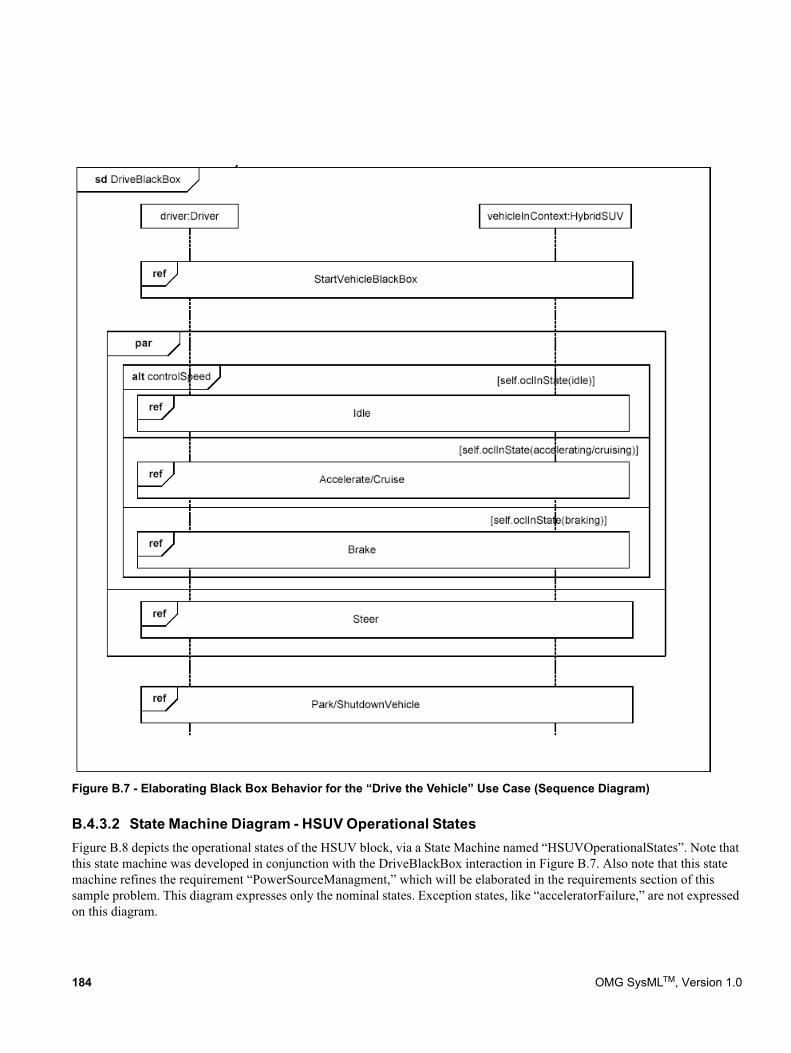
Figure B.7 - Elaborating Black Box Behavior for the “Drive the Vehicle” Use Case (Sequence Diagram)
B.4.3.2 State Machine Diagram - HSUV Operational StatesFigure B.8 depicts the operational states of the HSUV block, via a State Machine named “HSUVOperationalStates”. Note that this state machine was developed in conjunction with the DriveBlackBox interaction in Figure B.7. Also note that this state machine refines the requirement “PowerSourceManagment,” which will be elaborated in the requirements section of this sample problem. This diagram expresses only the nominal states. Exception states, like “acceleratorFailure,” are not expressed on this diagram.
184 OMG SysMLTM, Version 1.0
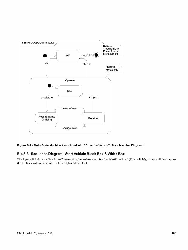
Figure B.8 - Finite State Machine Associated with “Drive the Vehicle” (State Machine Diagram)
B.4.3.3 Sequence Diagram - Start Vehicle Black Box & White BoxThe Figure B.9 shows a “black box” interaction, but references “StartVehicleWhiteBox” (Figure B.10), which will decompose the lifelines within the context of the HybridSUV block.
stm HSUVOperationalStates
Operate
Idle
Accellerating/Cruising Braking
engageBrake
accelerate stopped
releaseBrake
shutOff
Off
start
keyOff
Refines«requirement»PowerSourceManagement
Nominalstates only
OMG SysMLTM, Version 1.0 185
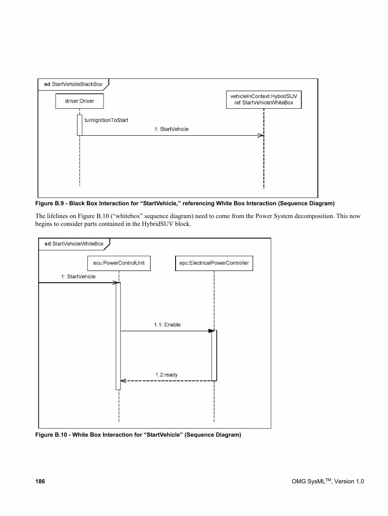
Figure B.9 - Black Box Interaction for “StartVehicle,” referencing White Box Interaction (Sequence Diagram)
The lifelines on Figure B.10 (“whitebox” sequence diagram) need to come from the Power System decomposition. This now begins to consider parts contained in the HybridSUV block.
Figure B.10 - White Box Interaction for “StartVehicle” (Sequence Diagram)
186 OMG SysMLTM, Version 1.0
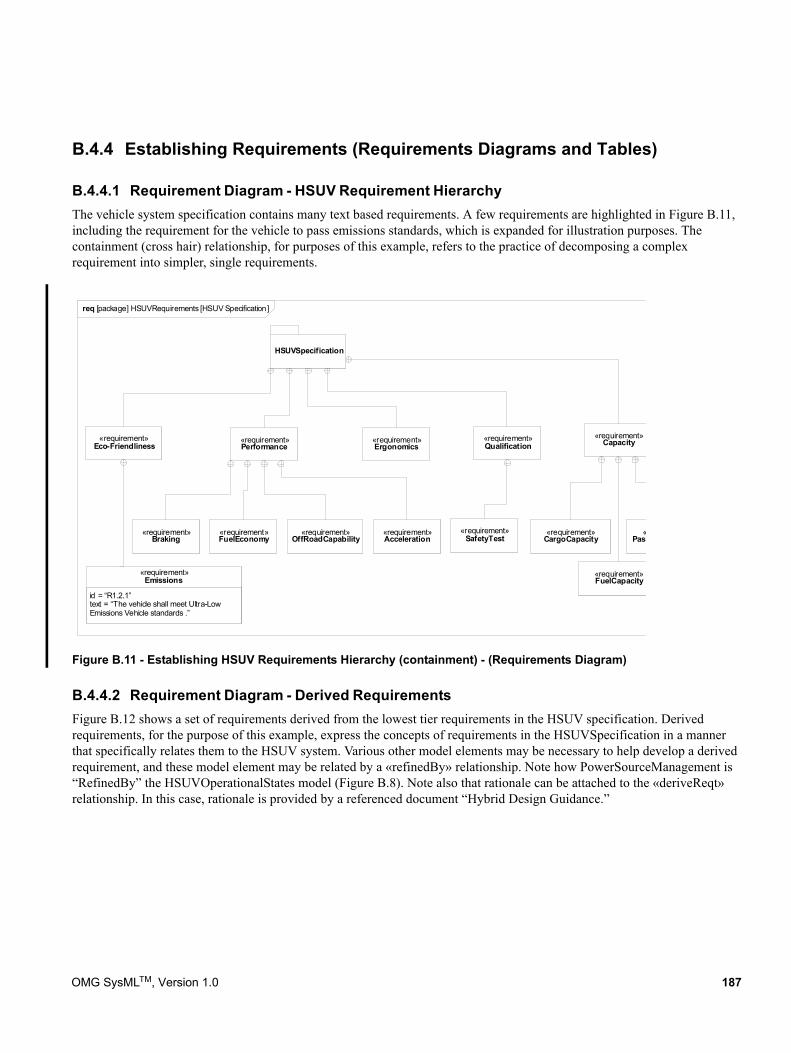
B.4.4 Establishing Requirements (Requirements Diagrams and Tables)
B.4.4.1 Requirement Diagram - HSUV Requirement HierarchyThe vehicle system specification contains many text based requirements. A few requirements are highlighted in Figure B.11, including the requirement for the vehicle to pass emissions standards, which is expanded for illustration purposes. The containment (cross hair) relationship, for purposes of this example, refers to the practice of decomposing a complex requirement into simpler, single requirements.
Figure B.11 - Establishing HSUV Requirements Hierarchy (containment) - (Requirements Diagram)
B.4.4.2 Requirement Diagram - Derived RequirementsFigure B.12 shows a set of requirements derived from the lowest tier requirements in the HSUV specification. Derived requirements, for the purpose of this example, express the concepts of requirements in the HSUVSpecification in a manner that specifically relates them to the HSUV system. Various other model elements may be necessary to help develop a derived requirement, and these model element may be related by a «refinedBy» relationship. Note how PowerSourceManagement is “RefinedBy” the HSUVOperationalStates model (Figure B.8). Note also that rationale can be attached to the «deriveReqt» relationship. In this case, rationale is provided by a referenced document “Hybrid Design Guidance.”
«requirement»Eco-Friendliness
«requirement»Performance
«requirement»Capacity«requirement»
Ergonomics
«requirement»Braking
«requirement»FuelEconomy
«requirement»OffRoadCapability
«requirement»Acceleration
id = “R1.2.1”text = “The vehicle shall meet Ultra-Low Emissions Vehicle standards .”
«requirement»Emissions
«Pass
«requirement»FuelCapacity
«requirement»CargoCapacity
HSUVSpecification
«requirement»Qualification
«requirement»SafetyTest
req [package] HSUVRequirements [HSUV Specification]
OMG SysMLTM, Version 1.0 187
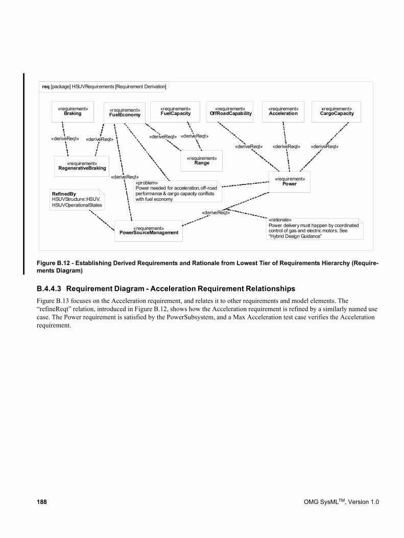
Figure B.12 - Establishing Derived Requirements and Rationale from Lowest Tier of Requirements Hierarchy (Require-ments Diagram)
B.4.4.3 Requirement Diagram - Acceleration Requirement RelationshipsFigure B.13 focuses on the Acceleration requirement, and relates it to other requirements and model elements. The “refineReqt” relation, introduced in Figure B.12, shows how the Acceleration requirement is refined by a similarly named use case. The Power requirement is satisfied by the PowerSubsystem, and a Max Acceleration test case verifies the Acceleration requirement.
«requirement»Braking «requirement»
FuelEconomy
«requirement»RegenerativeBraking
«requirement»PowerSourceManagement
«requirement»Power
«deriveReqt»«deriveReqt»
«deriveReqt»
«deriveReqt»
«requirement»Acceleration
«requirement»CargoCapacity
«requirement»FuelCapacity
«requirement»OffRoadCapability
«requirement»Range
«deriveReqt» «deriveReqt»
«deriveReqt» «deriveReqt» «deriveReqt»
RefinedByHSUVStructure::HSUV.HSUVOperationalStates
«rationale»Power delivery must happen by coordinated control of gas and electric motors. See “Hybrid Design Guidance”
«problem»Power needed for acceleration, off-road performance & cargo capacity conflicts with fuel economy
req [package] HSUVRequirements [Requirement Derivation]
188 OMG SysMLTM, Version 1.0
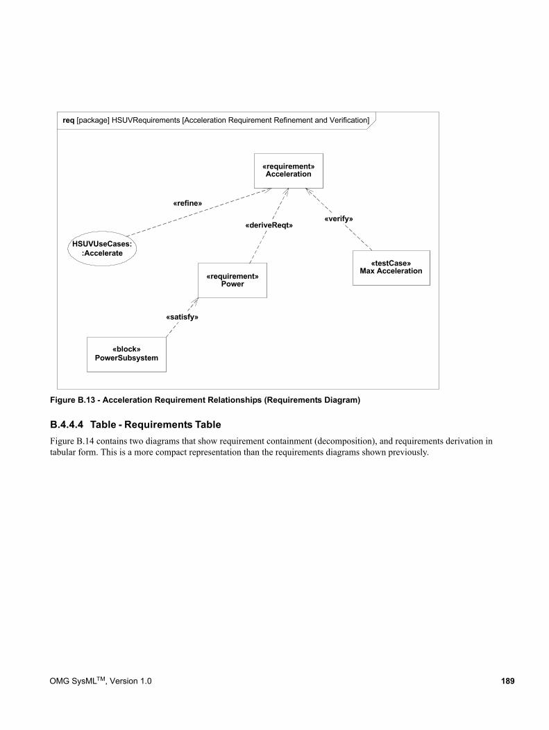
Figure B.13 - Acceleration Requirement Relationships (Requirements Diagram)
B.4.4.4 Table - Requirements TableFigure B.14 contains two diagrams that show requirement containment (decomposition), and requirements derivation in tabular form. This is a more compact representation than the requirements diagrams shown previously.
req [package] HSUVRequirements [Acceleration Requirement Refinement and Verification]
«requirement»Acceleration
HSUVUseCases::Accelerate
«block»PowerSubsystem
«refine»
«satisfy»
«requirement»Power
«deriveReqt»
«testCase»Max Acceleration
«verify»
OMG SysMLTM, Version 1.0 189
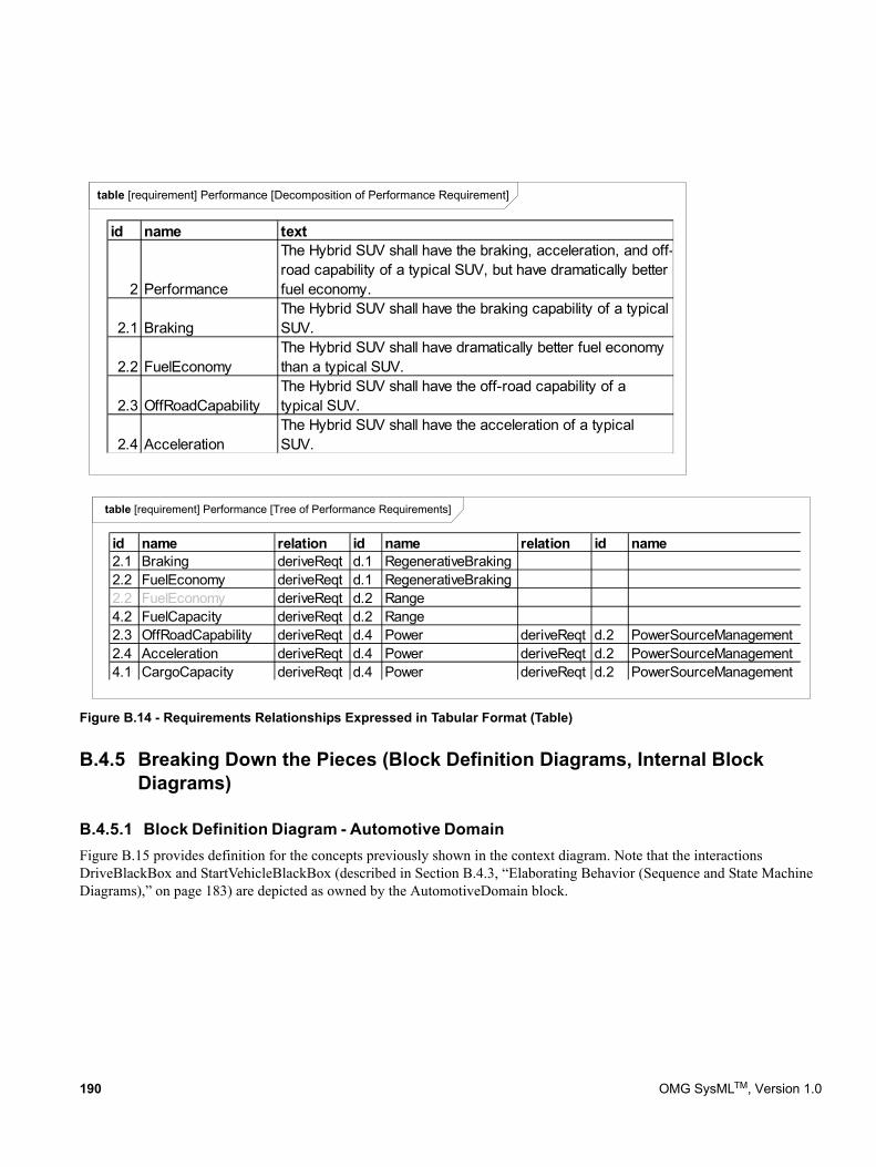
Figure B.14 - Requirements Relationships Expressed in Tabular Format (Table)
B.4.5 Breaking Down the Pieces (Block Definition Diagrams, Internal Block Diagrams)
B.4.5.1 Block Definition Diagram - Automotive Domain Figure B.15 provides definition for the concepts previously shown in the context diagram. Note that the interactions DriveBlackBox and StartVehicleBlackBox (described in Section B.4.3, “Elaborating Behavior (Sequence and State Machine Diagrams),” on page 183) are depicted as owned by the AutomotiveDomain block.
table [requirement] Performance [Decomposition of Performance Requirement]
id name text
2 Performance
The Hybrid SUV shall have the braking, acceleration, and off-road capability of a typical SUV, but have dramatically better fuel economy.
2.1 BrakingThe Hybrid SUV shall have the braking capability of a typical SUV.
2.2 FuelEconomyThe Hybrid SUV shall have dramatically better fuel economy than a typical SUV.
2.3 OffRoadCapabilityThe Hybrid SUV shall have the off-road capability of a typical SUV.
2.4 AccelerationThe Hybrid SUV shall have the acceleration of a typical SUV.
table [requirement] Performance [Tree of Performance Requirements]
id name relation id name relation id name2.1 Braking deriveReqt d.1 RegenerativeBraking2.2 FuelEconomy deriveReqt d.1 RegenerativeBraking2.2 FuelEconomy deriveReqt d.2 Range4.2 FuelCapacity deriveReqt d.2 Range2.3 OffRoadCapability deriveReqt d.4 Power deriveReqt d.2 PowerSourceManagement2.4 Acceleration deriveReqt d.4 Power deriveReqt d.2 PowerSourceManagement4.1 CargoCapacity deriveReqt d.4 Power deriveReqt d.2 PowerSourceManagement
190 OMG SysMLTM, Version 1.0
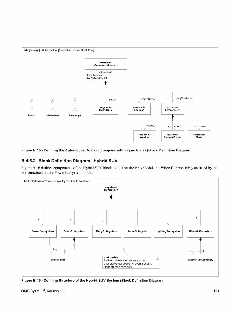
Figure B.15 - Defining the Automotive Domain (compare with Figure B.4 ) - (Block Definition Diagram)
B.4.5.2 Block Definition Diagram - Hybrid SUVFigure B.16 defines components of the HybridSUV block Note that the BrakePedal and WheelHubAssembly are used by, but not contained in, the PowerSubsystem block.
Figure B.16 - Defining Structure of the Hybrid SUV System (Block Definition Diagram)
bdd [package] HSUVStructure [Automotive Domain Breakdown]
interactionsDriveBlackBoxStartVehicleBlackBox
«domain»AutomotiveDomain
«system»HybridSUV
«external»Baggage
Driver Maintainer Passenger
«external»Environment
«external»Road
1..* road
drivingConditionsvehicleCargoHSUV
«external»Weather
«external»ExternalObject
1..* objectweather
bdd [block] AutomotiveDomain [HybridSUV Breakdown]
«system»HybridSUV
PowerSubsystem
p clibbk
BrakePedal
bkp
ChassisSubsytemBrakeSubsystem InteriorSubsystem LightingSubsystemBodySubsystem
WheelHubAssembly
42
«rationale»2 wheel drive is the only way to getacceptable fuel economy, even though itlimits off-road capability
OMG SysMLTM, Version 1.0 191
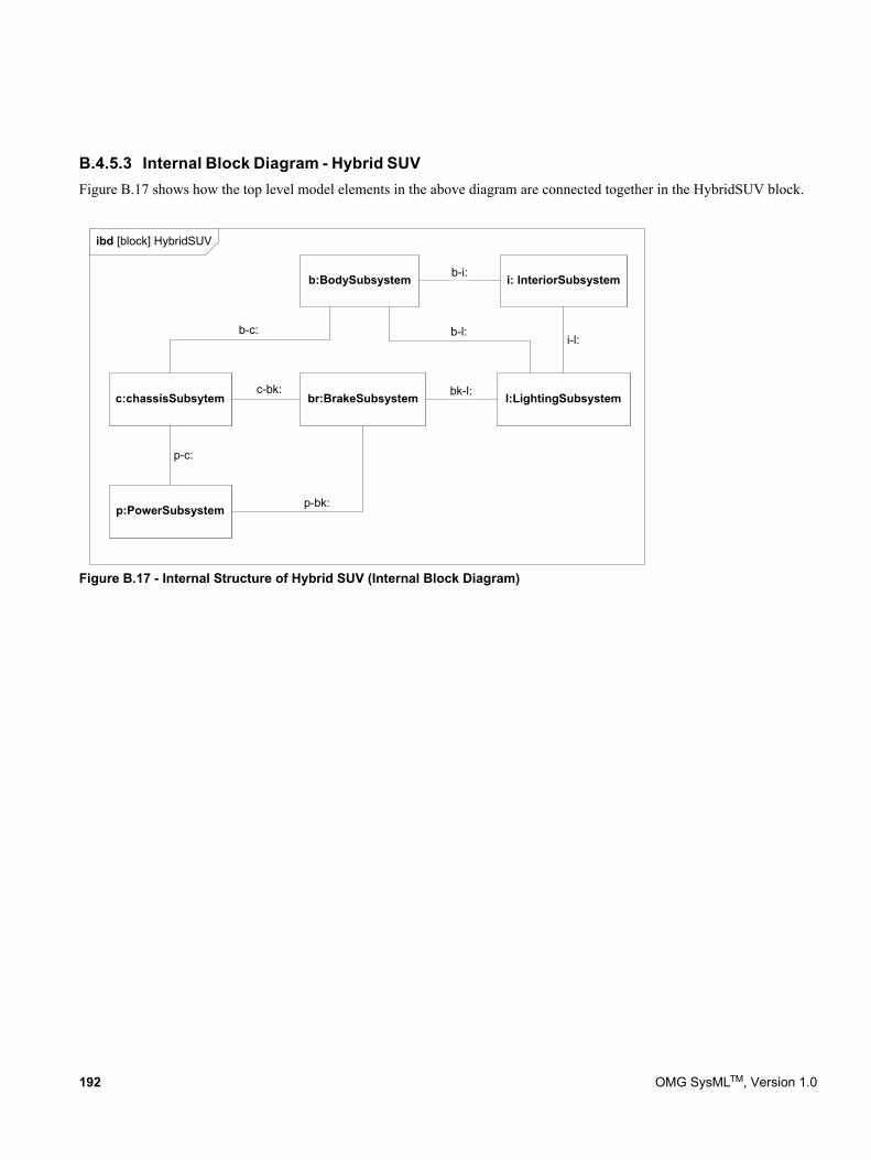
B.4.5.3 Internal Block Diagram - Hybrid SUVFigure B.17 shows how the top level model elements in the above diagram are connected together in the HybridSUV block.
Figure B.17 - Internal Structure of Hybrid SUV (Internal Block Diagram)
ibd [block] HybridSUV
p:PowerSubsystem
c:chassisSubsytem br:BrakeSubsystem
i: InteriorSubsystem
l:LightingSubsystem
b:BodySubsystem
c-bk:
b-c:
b-i:
i-l:b-l:
bk-l:
p-c:
p-bk:
192 OMG SysMLTM, Version 1.0
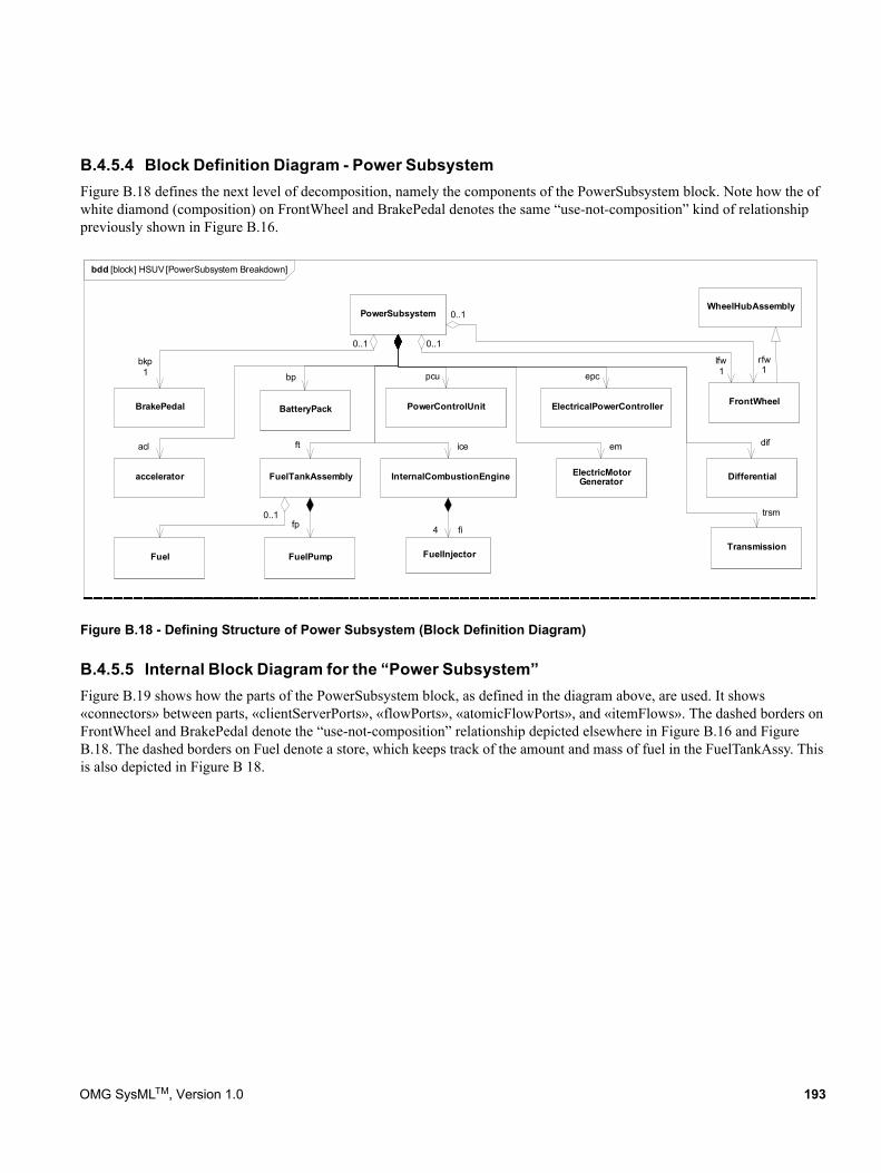
B.4.5.4 Block Definition Diagram - Power SubsystemFigure B.18 defines the next level of decomposition, namely the components of the PowerSubsystem block. Note how the of white diamond (composition) on FrontWheel and BrakePedal denotes the same “use-not-composition” kind of relationship previously shown in Figure B.16.
Figure B.18 - Defining Structure of Power Subsystem (Block Definition Diagram)
B.4.5.5 Internal Block Diagram for the “Power Subsystem” Figure B.19 shows how the parts of the PowerSubsystem block, as defined in the diagram above, are used. It shows «connectors» between parts, «clientServerPorts», «flowPorts», «atomicFlowPorts», and «itemFlows». The dashed borders on FrontWheel and BrakePedal denote the “use-not-composition” relationship depicted elsewhere in Figure B.16 and Figure B.18. The dashed borders on Fuel denote a store, which keeps track of the amount and mass of fuel in the FuelTankAssy. This is also depicted in Figure B 18.
bdd [block] HSUV [PowerSubsystem Breakdown]
PowerSubsystem
ElectricMotorGenerator
FrontWheel
accelerator FuelTankAssembly Differential
Transmission
InternalCombustionEngine
FuelInjector
lfw1
0..1
dif
trsm
emiceftacl
fi4
BatteryPack ElectricalPowerController
bp
PowerControlUnit
FuelPump
epcpcu
BrakePedal
0..1
bkp1
fp
WheelHubAssembly
rfw1
0..1
0..1
Fuel
OMG SysMLTM, Version 1.0 193
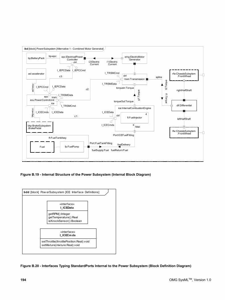
Figure B.19 - Internal Structure of the Power Subsystem (Internal Block Diagram)
Figure B.20 - Interfaces Typing StandardPorts Internal to the Power Subsystem (Block Definition Diagram)
ibd [block] PowerSubsystem [Alternative 1 - Combined Motor Generator]
emg:ElectricMotorGenerator
trsm:Transmission
ice:InternalCombustionEngine
acl:accelerator
ecu:PowerControlUnit
ft:FuelTankAssy
dif:Differential
rfw:ChassisSubsytem.FrontWheel
lfw:ChassisSubsytem.FrontWheel
Port:FuelTankFitting
Port:ICEFuelFitting
fuelDelivery
torqueOut:Torque
torquein:Torque
spline
fuelSupply:Fuel
epc:ElectricalPowerControllerbp:BatteryPack
bp-epc:
i1:ElectricCurrent
i2:ElectricCurrent
fp:FuelPump
fi:FuelInjector
4fdist:bkp:BrakeSubsystem
.BrakePedal
<>
<>
<><>
4
fuelReturn:Fuel
<>
<>
<>
<>
g1:T
orqu
e t2:T
orqu
e
t1:Torque
ice
ctrlI_ICECmds
I_ICECmds
ctrl
ctrl
I_ICEData I_ICEData
trsmepc
c3:
c2:
c1:
I_IEPCCmdI_IEPCData
I_IEPCDataI_EPCCmd
I_TRSMData
I_TRSMCmd
I_TRSMCmd
I_TRSMData
<><>
<>
rightHalfShaft
<><>
<>
leftHalfShaft
acl-e
cu:
bkp-
ecu:
Fuel <>
getRPM():IntegergetTemperature():RealisKnockSensor():Boolean
«interface»I_ICEData
setThrottle(throttlePosition:Real):voidsetMixture(mixture:Real):void
«interface»I_ICECm ds
bdd [block] Pow erSubsystem [ICE Interface Def initions]
194 OMG SysMLTM, Version 1.0
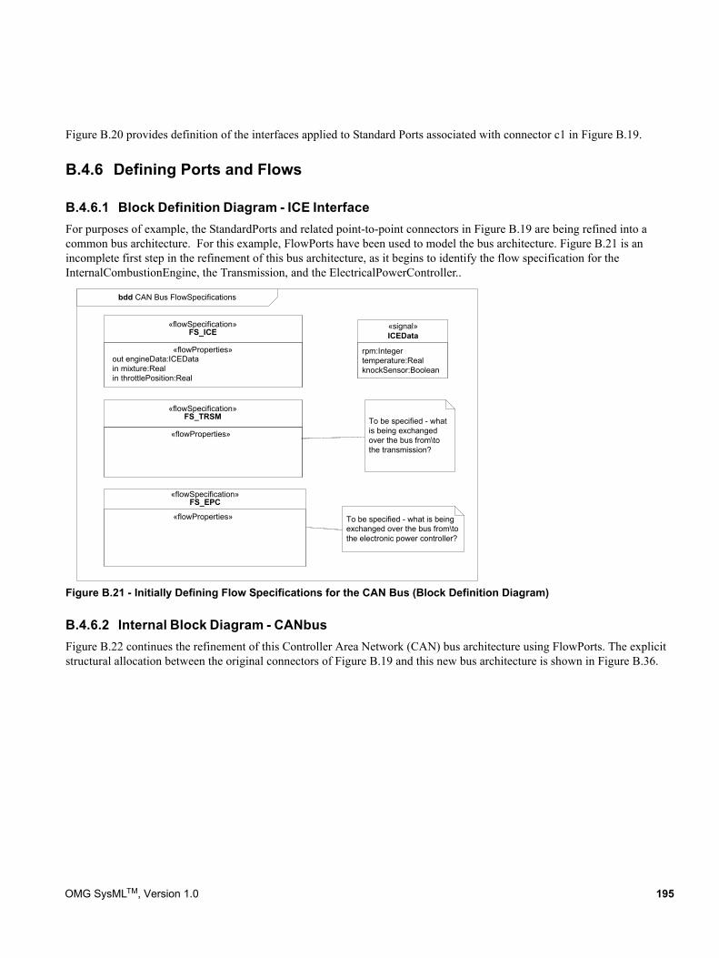
Figure B.20 provides definition of the interfaces applied to Standard Ports associated with connector c1 in Figure B.19.
B.4.6 Defining Ports and Flows
B.4.6.1 Block Definition Diagram - ICE InterfaceFor purposes of example, the StandardPorts and related point-to-point connectors in Figure B.19 are being refined into a common bus architecture. For this example, FlowPorts have been used to model the bus architecture. Figure B.21 is an incomplete first step in the refinement of this bus architecture, as it begins to identify the flow specification for the InternalCombustionEngine, the Transmission, and the ElectricalPowerController..
Figure B.21 - Initially Defining Flow Specifications for the CAN Bus (Block Definition Diagram)
B.4.6.2 Internal Block Diagram - CANbusFigure B.22 continues the refinement of this Controller Area Network (CAN) bus architecture using FlowPorts. The explicit structural allocation between the original connectors of Figure B.19 and this new bus architecture is shown in Figure B.36.
bdd CAN Bus FlowSpecifications
«flowProperties»out engineData:ICEDatain mixture:Realin throttlePosition:Real
«flowSpecification»FS_ICE
«flowProperties»
«flowSpecification»FS_TRSM
«flowProperties»
«flowSpecification»FS_EPC
rpm:Integertemperature:RealknockSensor:Boolean
«signal»ICEData
To be specified - whatis being exchangedover the bus from\tothe transmission?
To be specified - what is beingexchanged over the bus from\tothe electronic power controller?
OMG SysMLTM, Version 1.0 195
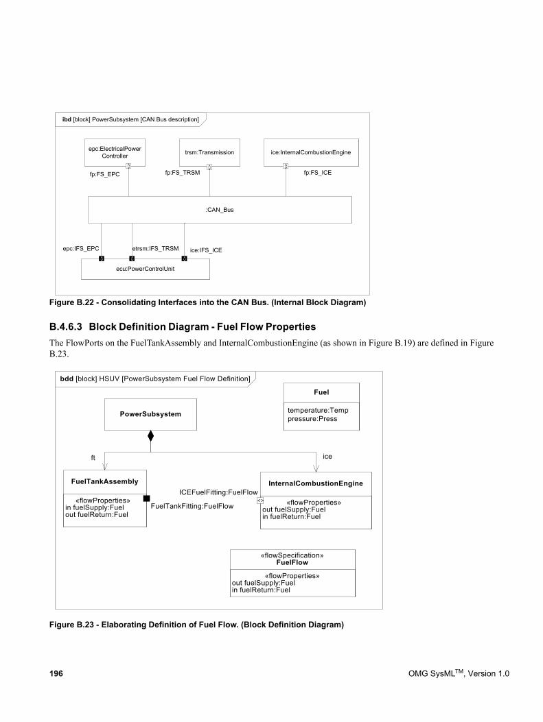
Figure B.22 - Consolidating Interfaces into the CAN Bus. (Internal Block Diagram)
B.4.6.3 Block Definition Diagram - Fuel Flow PropertiesThe FlowPorts on the FuelTankAssembly and InternalCombustionEngine (as shown in Figure B.19) are defined in Figure B.23.
Figure B.23 - Elaborating Definition of Fuel Flow. (Block Definition Diagram)
ibd [block] PowerSubsystem [CAN Bus description]
trsm:Transmission ice:InternalCombustionEngine
ecu:PowerControlUnit
epc:ElectricalPowerController
:CAN_Bus
fp:FS_EPC fp:FS_TRSM fp:FS_ICE
epc:IFS_EPC etrsm:IFS_TRSM ice:IFS_ICE
<> <> <>
<> <> <>
bdd [block] HSUV [PowerSubsystem Fuel Flow Definition]
temperature:Temppressure:Press
Fuel
«flowProperties» out fuelSupply:Fuel in fuelReturn:Fuel
«flowSpecification»FuelFlow
PowerSubsystem
«flowProperties» in fuelSupply:Fuel out fuelReturn:Fuel
FuelTankAssembly
«flowProperties» out fuelSupply:Fuel in fuelReturn:Fuel
InternalCombustionEngine
iceft
FuelTankFitting:FuelFlow
ICEFuelFitting:FuelFlow<>
<>
196 OMG SysMLTM, Version 1.0
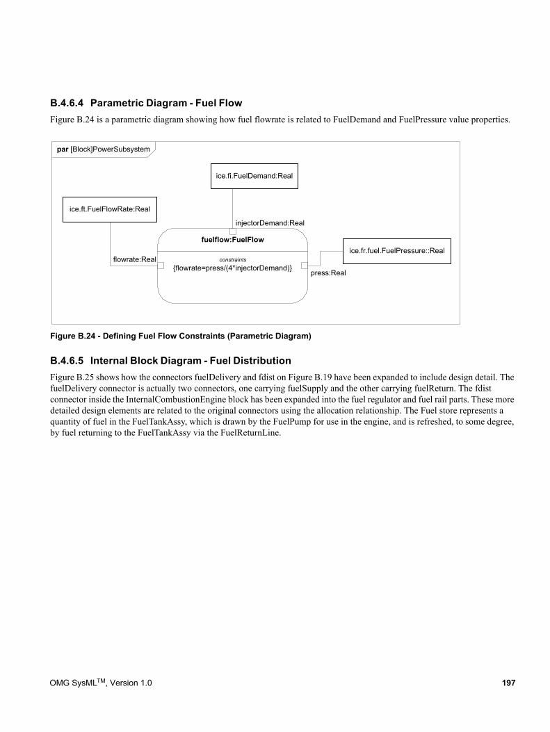
B.4.6.4 Parametric Diagram - Fuel Flow Figure B.24 is a parametric diagram showing how fuel flowrate is related to FuelDemand and FuelPressure value properties.
Figure B.24 - Defining Fuel Flow Constraints (Parametric Diagram)
B.4.6.5 Internal Block Diagram - Fuel DistributionFigure B.25 shows how the connectors fuelDelivery and fdist on Figure B.19 have been expanded to include design detail. The fuelDelivery connector is actually two connectors, one carrying fuelSupply and the other carrying fuelReturn. The fdist connector inside the InternalCombustionEngine block has been expanded into the fuel regulator and fuel rail parts. These more detailed design elements are related to the original connectors using the allocation relationship. The Fuel store represents a quantity of fuel in the FuelTankAssy, which is drawn by the FuelPump for use in the engine, and is refreshed, to some degree, by fuel returning to the FuelTankAssy via the FuelReturnLine.
par [Block]PowerSubsystem
constraints{flowrate=press/(4*injectorDemand)}
fuelflow:FuelFlow
press:Real
injectorDemand:Real
ice.fr.fuel.FuelPressure::Real
ice.fi.FuelDemand:Real
flowrate:Real
ice.ft.FuelFlowRate:Real
OMG SysMLTM, Version 1.0 197
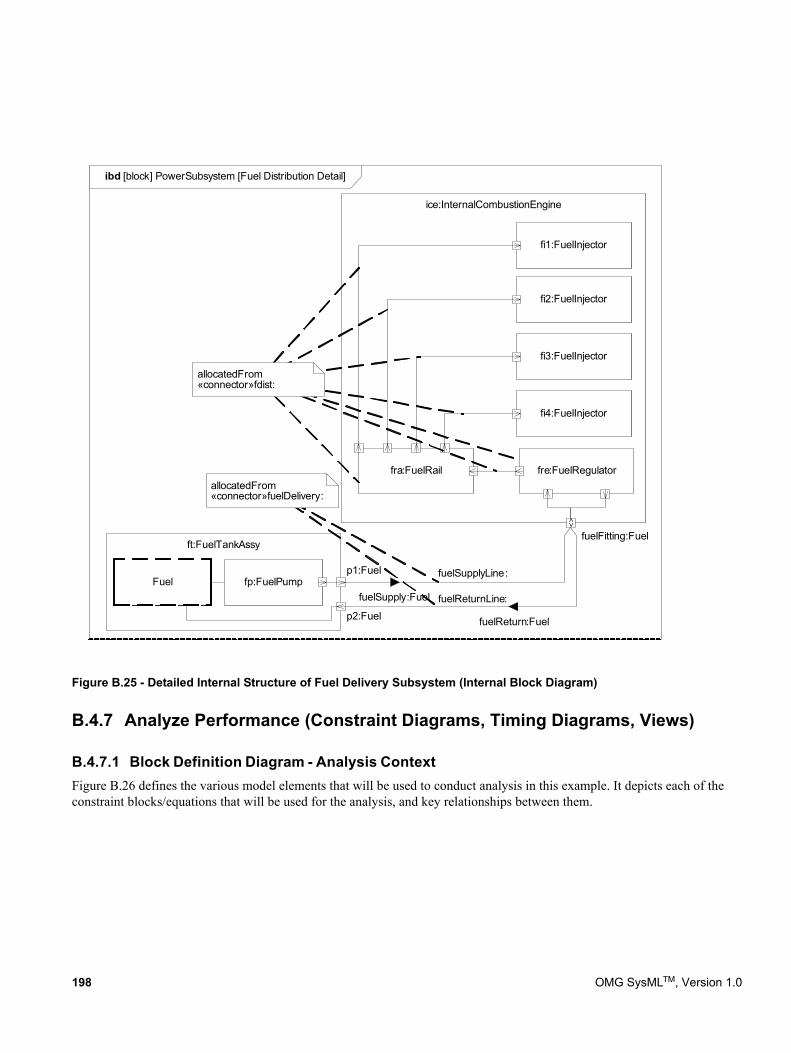
Figure B.25 - Detailed Internal Structure of Fuel Delivery Subsystem (Internal Block Diagram)
B.4.7 Analyze Performance (Constraint Diagrams, Timing Diagrams, Views)
B.4.7.1 Block Definition Diagram - Analysis ContextFigure B.26 defines the various model elements that will be used to conduct analysis in this example. It depicts each of the constraint blocks/equations that will be used for the analysis, and key relationships between them.
ibd [block] PowerSubsystem [Fuel Distribution Detail]
ice:InternalCombustionEngine
ft:FuelTankAssy
fuelSupplyLine:
fuelSupply:Fuelfp:FuelPump
fi1:FuelInjector
4
fuelReturn:Fuel
fre:FuelRegulatorfra:FuelRail
p1:Fuel
p2:FuelfuelReturnLine:
fi2:FuelInjector
fi3:FuelInjector
fi4:FuelInjector
allocatedFrom«connector»fdist:
fuelFitting:Fuel
allocatedFrom«connector»fuelDelivery:
<>Fuel
198 OMG SysMLTM, Version 1.0
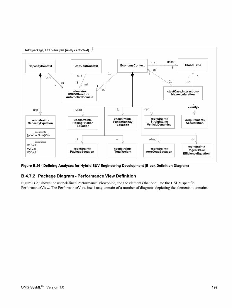
Figure B.26 - Defining Analyses for Hybrid SUV Engineering Development (Block Definition Diagram)
B.4.7.2 Package Diagram - Performance View DefinitionFigure B.27 shows the user-defined Performance Viewpoint, and the elements that populate the HSUV specific PerformanceView. The PerformanceView itself may contain of a number of diagrams depicting the elements it contains.
bdd [package] HSUVAnalysis [Analysis Context]
«constraint»RollingFriction
Equation
«constraint»AeroDragEquation
adrag
rdrag dyn
«constraint»StraightLine
VehicleDynamics
«testCase,Interaction»MaxAcceleration
1
0..1
ex
«requirement»Acceleration
«verify»
GlobalTimedelta-t0..1
1
t
0..1
1
UnitCostContext
«domain»HSUVStructure::
AutomotiveDomain
ad
0..1
1ad
0..1
1ad0..1
1
parametersV1:VolV2:VolV3:Vol
constraints{pcap = Sum(Vi)}
«constraint»CapacityEquation
EconomyContextCapacityContext
cap
«constraint»PayloadEquation
«constraint»TotalWeight
«constraint»FuelEfficency
Equation
pl
fe
w
«constraint»RegenBrake
EfficiencyEquation
rb
OMG SysMLTM, Version 1.0 199
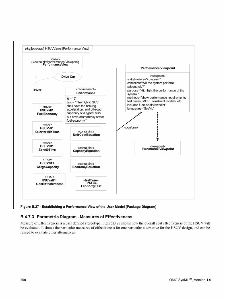
Figure B.27 - Establishing a Performance View of the User Model (Package Diagram)
B.4.7.3 Parametric Diagram - Measures of EffectivenessMeasure of Effectiveness is a user defined stereotype. Figure B.28 shows how the overall cost effectiveness of the HSUV will be evaluated. It shows the particular measures of effectiveness for one particular alternative for the HSUV design, and can be reused to evaluate other alternatives.
«view»{viewpoint=Performance Viewpoint}
PerformanceView
Driver
Drive Car
id = “2"text = "The Hybrid SUV shall have the braking, acceleration, and off-road capability of a typical SUV, but have dramatically better fuel economy."
«requirement»Performance
«moe»HSUValt1.
CostEffectiveness
«moe»HSUValt1.
FuelEconomy
«moe»HSUValt1.
Zero60Time
«moe»HSUValt1.
CargoCapacity
«moe»HSUValt1.
QuarterMileTime
«constraint»EconomyEquation
«constraint»UnitCostEquation
«constraint»CapacityEquation
«testCase»EPAFuel
EconomyTest
«viewpoint»stakeholders="customer"concerns="Will the system perform adequately?"purpose="Highlight the performance of the system."methods="show performance requirements, test cases, MOE, constraint models, etc.; includes functional viewpoint "languages="SysML"
Performance Viewpoint
«viewpoint»Functional Viewpoint
«conform»
pkg [package] HSUVViews [Performance View]
200 OMG SysMLTM, Version 1.0
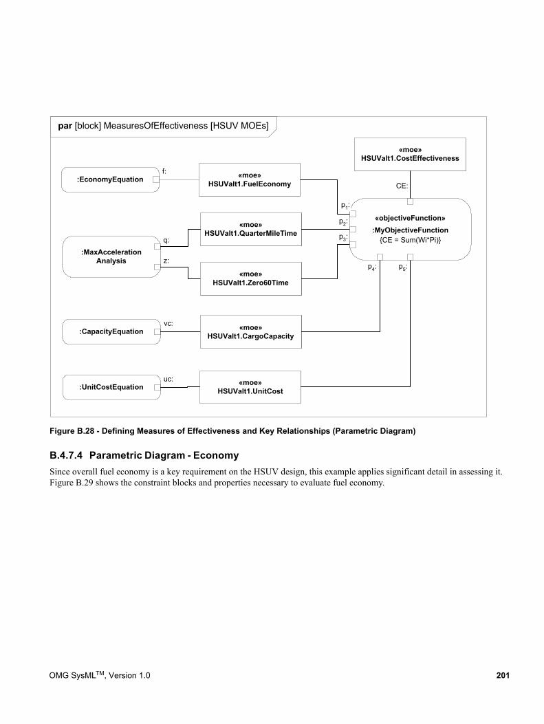
Figure B.28 - Defining Measures of Effectiveness and Key Relationships (Parametric Diagram)
B.4.7.4 Parametric Diagram - EconomySince overall fuel economy is a key requirement on the HSUV design, this example applies significant detail in assessing it. Figure B.29 shows the constraint blocks and properties necessary to evaluate fuel economy.
par [block] MeasuresOfEffectiveness [HSUV MOEs]
«objectiveFunction»:MyObjectiveFunction
{CE = Sum(Wi*Pi)}
«moe»HSUValt1.CostEffectiveness
«moe»HSUValt1.FuelEconomy
«moe»HSUValt1.Zero60Time
«moe»HSUValt1.CargoCapacity
«moe»HSUValt1.QuarterMileTime
«moe»HSUValt1.UnitCost
:EconomyEquationf:
:MaxAccelerationAnalysis
q:
z:
:CapacityEquationvc:
:UnitCostEquationuc:
p4:
p1:
p2:
p3:
p5:
CE:
OMG SysMLTM, Version 1.0 201
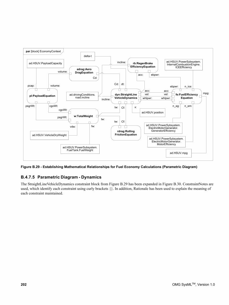
Figure B.29 - Establishing Mathematical Relationships for Fuel Economy Calculations (Parametric Diagram)
B.4.7.5 Parametric Diagram - DynamicsThe StraightLineVehicleDynamics constraint block from Figure B.29 has been expanded in Figure B.30. ConstraintNotes are used, which identify each constraint using curly brackets {}. In addition, Rationale has been used to explain the meaning of each constraint maintained.
par [block] EconomyContext
dyn:StraightLineVehicleDynamics
rdrag:RollingFrictionEquation
adrag:AeroDragEquation
w:TotalWeight
pl:PayloadEquation
cgoWt:psgrWt:
psgrWt:
volume:
volume:
vdw: fw:
ad.HSUV.PowerSubsystem.FuelTank.FuelWeight
Cd:
Cd:
tw:
tw:
tw:
Cf:
Cf:
fe:FuelEfficiencyEquationwhlpwr:
acc:acc:vel: mpg:
incline:
rb:RegenBrakeEfficiencyEquation
vel:
incline:
ebpwr:
ebpwr:
n_em:
acc:
n_ice:
n_eg:
ad.HSUV.PayloadCapacity
pcap:
cgoWt:
whlpwr:
ad.HSUV.VehicleDryWeight
ad.HSUV.PowerSybsystem.ElectricMotorGenerator.
GeneratorEfficiency
ad.HSUV.PowerSybsystem.ElectricMotorGenerator.
MotorEfficiency
ad.HSUV.PowerSybsystem.InternalCombustionEngine.
ICEEfficiency
ad.drivingConditions.road.incline
ad.HSUV.position
x:
ad.HSUV.mpg
dt:
delta-t
202 OMG SysMLTM, Version 1.0
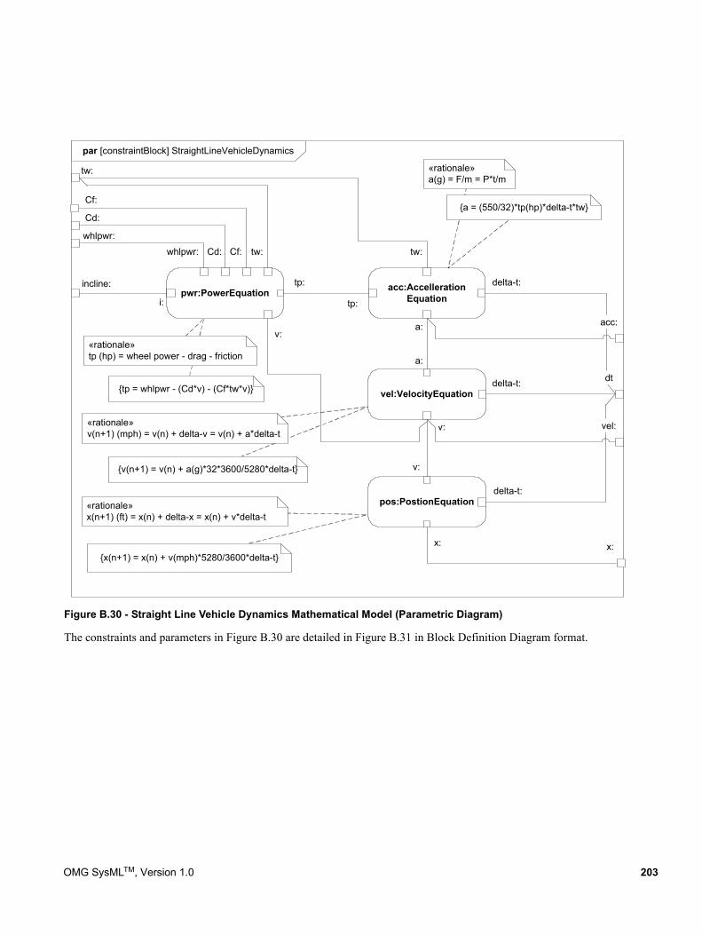
Figure B.30 - Straight Line Vehicle Dynamics Mathematical Model (Parametric Diagram)
The constraints and parameters in Figure B.30 are detailed in Figure B.31 in Block Definition Diagram format.
par [constraintBlock] StraightLineVehicleDynamics
acc:AccellerationEquation
vel:VelocityEquation
pos:PostionEquation
pwr:PowerEquation
whlpwr: tw:Cd: Cf:
tp:
tp:
delta-t:
delta-t:
delta-t:
tw:
tw:
a:
a:
v:
v:
acc:
vel:
Cf:
Cd:
whlpwr:
v:
x:
incline:
i:
{v(n+1) = v(n) + a(g)*32*3600/5280*delta-t}
{x(n+1) = x(n) + v(mph)*5280/3600*delta-t}
{tp = whlpwr - (Cd*v) - (Cf*tw*v)}
«rationale»tp (hp) = wheel power - drag - friction
«rationale»v(n+1) (mph) = v(n) + delta-v = v(n) + a*delta-t
«rationale»x(n+1) (ft) = x(n) + delta-x = x(n) + v*delta-t
«rationale»a(g) = F/m = P*t/m
{a = (550/32)*tp(hp)*delta-t*tw}
x:
dt
OMG SysMLTM, Version 1.0 203
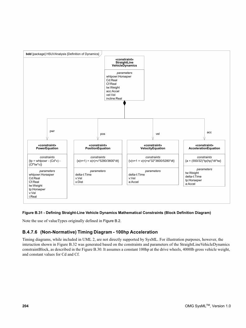
Figure B.31 - Defining Straight-Line Vehicle Dynamics Mathematical Constraints (Block Definition Diagram)
Note the use of valueTypes originally defined in Figure B.2.
B.4.7.6 (Non-Normative) Timing Diagram - 100hp AccelerationTiming diagrams, while included in UML 2, are not directly supported by SysML. For illustration purposes, however, the interaction shown in Figure B.32 was generated based on the constraints and parameters of the StraightLineVehicleDynamics constraintBlock, as described in the Figure B.30. It assumes a constant 100hp at the drive wheels, 4000lb gross vehicle weight, and constant values for Cd and Cf.
bdd [package] HSUVAnalysis [Definition of Dynamics]
parameterswhlpowr:HorsepwrCd:RealCf:Realtw:Weighttp:Horsepwrv:Veli:Real
constraints{tp = whlpowr - (Cd*v) -(Cf*tw*v)}
«constraint»PowerEquation
parameterstw:Weightdelta-t:Timetp:Horsepwra:Accel
constraints{a = (550/32)*tp(hp)*dt*tw}
«constraint»AccelerationEquation
parametersdelta-t:Timev:Vela:Accel
constraints{v(n+1 = v(n)+a*32*3600/5280*dt}
«constraint»VelocityEquation
parametersdelta-t:Timev:Velx:Dist
constraints{x(n+1) = x(n)+v*5280/3600*dt}
«constraint»PositionEquation
parameterswhlpowr:HorsepwrCd:RealCf:Realtw:Weightacc:Accelvel:Velincline:Real
«constraint»StraightLine
VehicleDynamics
accvelpwr
pos
204 OMG SysMLTM, Version 1.0
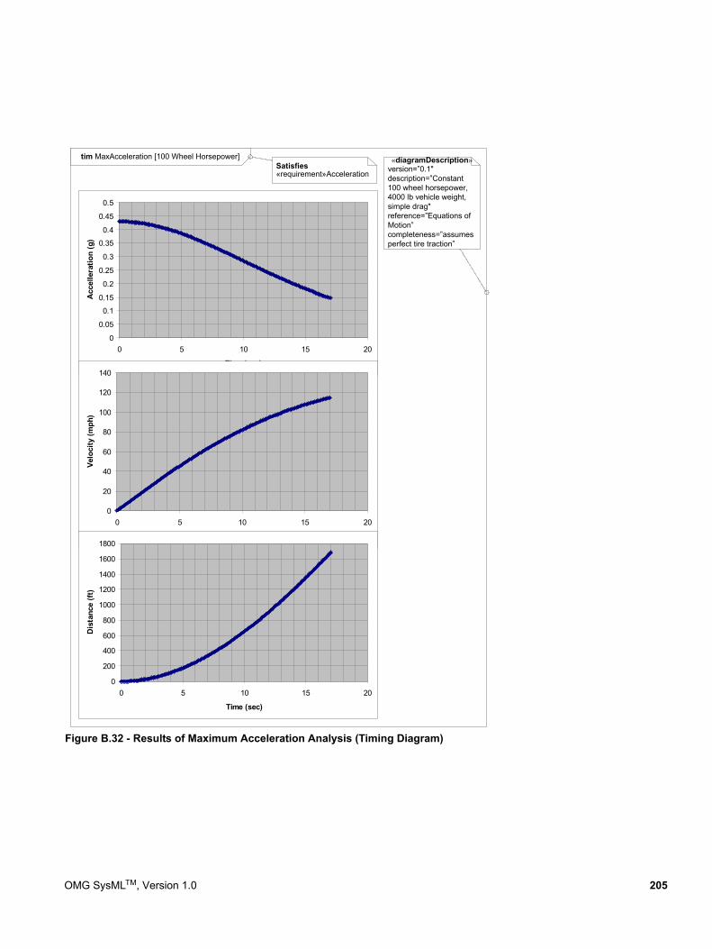
Figure B.32 - Results of Maximum Acceleration Analysis (Timing Diagram)
tim MaxAcceleration [100 Wheel Horsepower]
0
0.05
0.1
0.15
0.2
0.25
0.3
0.35
0.4
0.45
0.5
0 5 10 15 20
Time (sec)
Acc
elle
ratio
n (g
)
0
20
40
60
80
100
120
140
0 5 10 15 20
Time (sec)
Velo
city
(mph
)
0
200
400
600
800
1000
1200
1400
1600
1800
0 5 10 15 20
Time (sec)
Dis
tanc
e (f
t)
Satisfies«requirement»Acceleration
«diagramDescription»version=”0.1"description=”Constant100 wheel horsepower,4000 lb vehicle weight,simple drag"reference=”Equations ofMotion”completeness=”assumesperfect tire traction”
OMG SysMLTM, Version 1.0 205
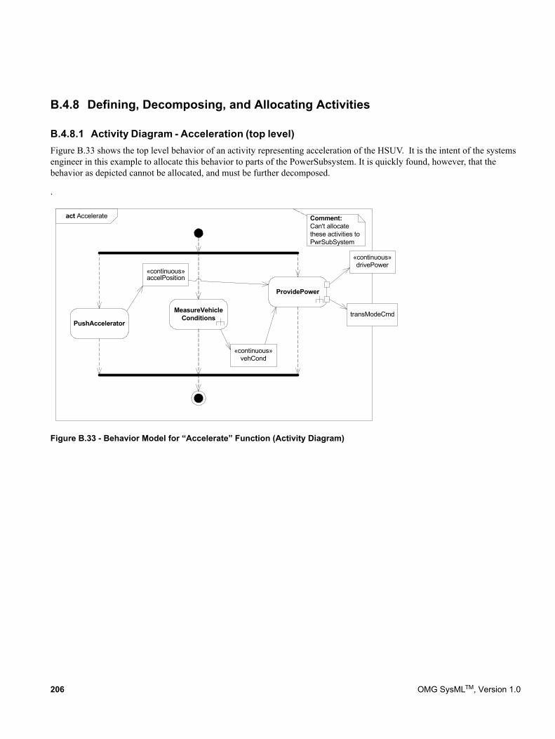
B.4.8 Defining, Decomposing, and Allocating Activities
B.4.8.1 Activity Diagram - Acceleration (top level)Figure B.33 shows the top level behavior of an activity representing acceleration of the HSUV. It is the intent of the systems engineer in this example to allocate this behavior to parts of the PowerSubsystem. It is quickly found, however, that the behavior as depicted cannot be allocated, and must be further decomposed.
.
Figure B.33 - Behavior Model for “Accelerate” Function (Activity Diagram)
act Accelerate
PushAccelerator
MeasureVehicleConditions
ProvidePower
«continuous»accelPosition
«continuous»vehCond
Comment:Can't allocatethese activities toPwrSubSystem
«continuous»drivePower
transModeCmd
206 OMG SysMLTM, Version 1.0
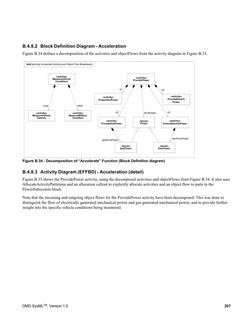
B.4.8.2 Block Definition Diagram - AccelerationFigure B.34 defines a decomposition of the activities and objectFlows from the activity diagram in Figure B.33.
Figure B.34 - Decomposition of “Accelerate” Function (Block Definition diagram)
B.4.8.3 Activity Diagram (EFFBD) - Acceleration (detail)Figure B.35 shows the ProvidePower activity, using the decomposed activities and objectFlows from Figure B.34. It also uses AllocateActivityPartitions and an allocation callout to explicitly allocate activities and an object flow to parts in the PowerSubsystem block.
Note that the incoming and outgoing object flows for the ProvidePower activity have been decomposed. This was done to distinguish the flow of electrically generated mechanical power and gas generated mechanical power, and to provide further insight into the specific vehicle conditions being monitored.
bdd [activity] Accelerate [Activity and Object Flow Breakdown]
«activity»MeasureVehicle
Conditions«activity»
ProvidePower
«activity»MeasureVehicle
Velocity
«activity»MeasureBattery
Condition«activity»
ProvideGasPower«activity»
ControlElectricPower
«activity»ProportionPower
«activity»ProvideElectric
Powermbatmvel
a4
a3a2
a1
drivePower
«block»Power
«block»GasPower
«block»ElecPower
gasDrivePower elecDrivePower
OMG SysMLTM, Version 1.0 207
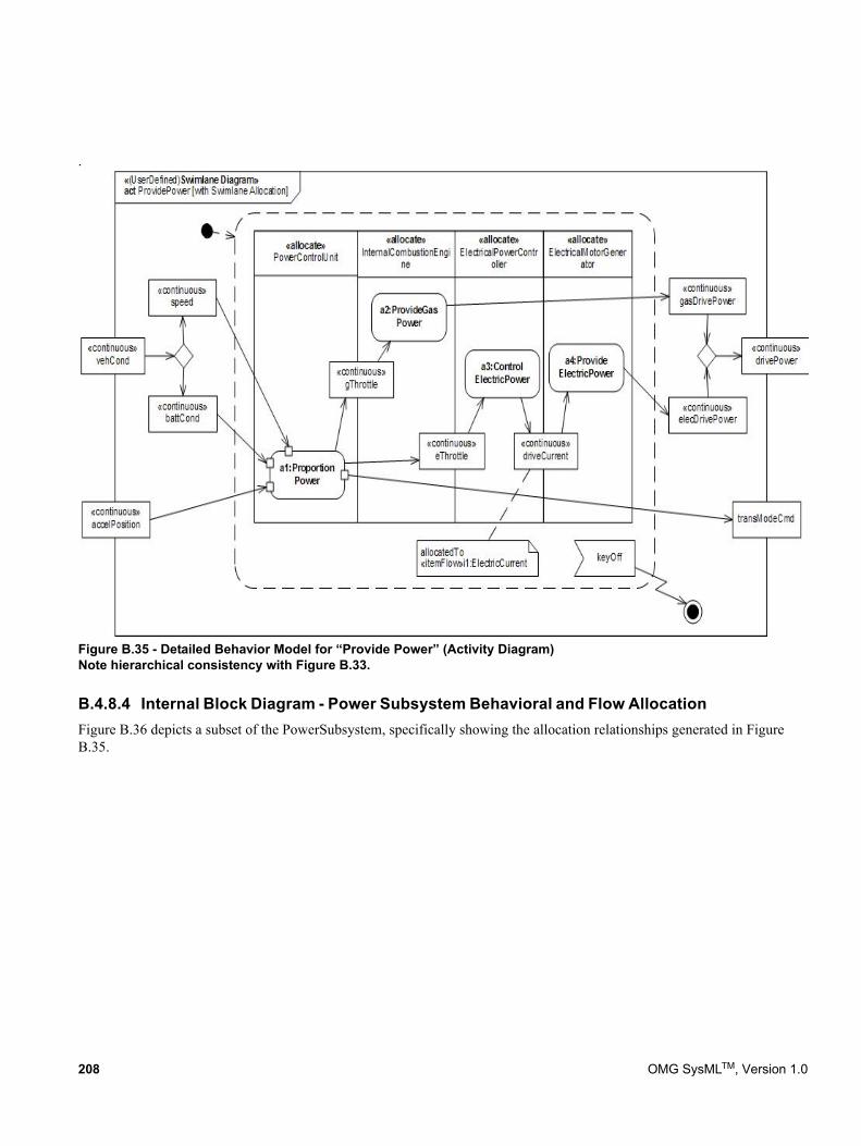
.
Figure B.35 - Detailed Behavior Model for “Provide Power” (Activity Diagram) Note hierarchical consistency with Figure B.33.
B.4.8.4 Internal Block Diagram - Power Subsystem Behavioral and Flow AllocationFigure B.36 depicts a subset of the PowerSubsystem, specifically showing the allocation relationships generated in Figure B.35.
208 OMG SysMLTM, Version 1.0
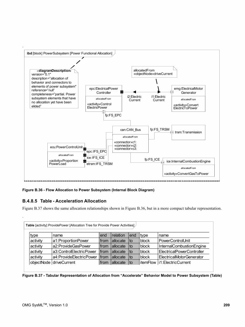
.
Figure B.36 - Flow Allocation to Power Subsystem (Internal Block Diagram)
B.4.8.5 Table - Acceleration AllocationFigure B.37 shows the same allocation relationships shown in Figure B.36, but in a more compact tabular representation.
.
Figure B.37 - Tabular Representation of Allocation from “Accelerate” Behavior Model to Power Subsystem (Table)
ibd [block] PowerSubsystem [Power Functional Allocation]
allocatedFrom
«activity»ConvertElectricToPower
emg:ElectricalMotorGenerator
trsm:Transmission
allocatedFrom
«activity»ConvertGasToPower
ice:InternalCombustionEngine
allocatedFrom
«activity»ProportionPowerLoad
ecu:PowerControlUnitepc:IFS_EPC
fp:FS_ICE
allocatedFrom
«activity»ControlElectricPower
epc:ElectricalPowerController
i1:ElectricCurrent
i2:ElectricCurrent
fp:FS_EPC
fp:FS_TRSM
allocatedFrom«objectNode»driveCurrent
allocatedFrom
«connector»c1: «connector»c2: «connector»c3:
can:CAN_Bus
ice:IFS_ICE
etrsm:IFS_TRSM
<>
<>
<>
<>
<>
<>
<>
<>
«diagramDescription»version=”0.1"description=”allocation of behavior and connectors to elements of power subsystem"reference=”null”completeness=”partial. Power subsystem elements that have no allocation yet have been elided”
Table [activity] ProvidePower [Allocation Tree for Provide Power Activities]
type name end relation end type nameactivity a1:ProportionPower from allocate to block PowerControlUnitactivity a2:ProvideGasPower from allocate to block InternalCombustionEngineactivity a3:ControlElectricPower from allocate to block ElectricalPowerControlleractivity a4:ProvideElectricPower from allocate to block ElectricalMotorGeneratorobjectNode driveCurrent from allocate to itemFlow i1:ElectricCurrent
OMG SysMLTM, Version 1.0 209
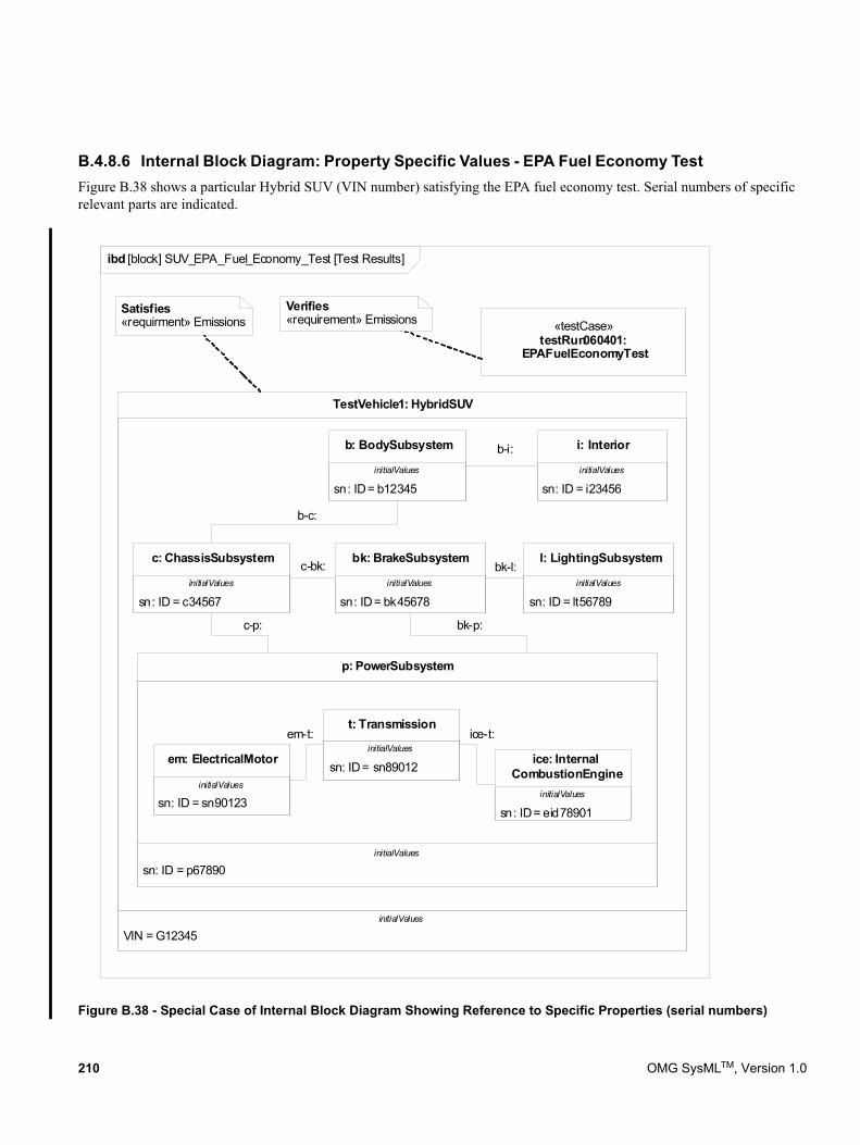
B.4.8.6 Internal Block Diagram: Property Specific Values - EPA Fuel Economy TestFigure B.38 shows a particular Hybrid SUV (VIN number) satisfying the EPA fuel economy test. Serial numbers of specific relevant parts are indicated.
Figure B.38 - Special Case of Internal Block Diagram Showing Reference to Specific Properties (serial numbers)
VIN = G12345
TestVehicle1: HybridSUV
sn: ID = p67890
p: PowerSubsystem
c-bk:
b-c:
b-i:
bk-l:
c-p: bk-p:
Satisfies«requirment» Emissions
sn: ID = bk45678
bk: BrakeSubsystem
sn: ID = c34567
c: ChassisSubsystem
sn: ID = lt56789
l: LightingSubsystem
sn: ID = b12345
b: BodySubsystem
sn: ID = i23456
i: Interior
«testCase»testRun060401:
EPAFuelEconomyTest
sn: ID = sn90123
em: ElectricalMotorsn: ID = sn89012
t: Transmissionem-t: ice-t:
Verifies«requirement» Emissions
sn: ID = eid78901
ice: InternalCombustionEngine
initialValues initialValues
initialValuesinitialValuesinitialValues
initialValues
initialValuesinitialValues
initialValues
initialValues
ibd [block] SUV_EPA_Fuel_Economy_Test [Test Results]
210 OMG SysMLTM, Version 1.0
Annex C: Non-normative Extensions
(informative)
This annex describes useful non-normative extensions to SysML that may be considered for standardization in future versions of the language.
Non-normative extensions consist of stereotypes and model libraries and are organized by major diagram type, consistent with how the main body of this specification is organized. Stereotypes in this section are specified using a tabular format, consistent with how non-normative stereotypes are specified in the UML 2 Superstructure specification. Model libraries are specified using the guidelines provided in the Profiles & Model Libraries chapter of this specification.
C.1 Activity Diagram Extensions
C.1.1 OverviewTwo non-normative extensions to activities are described for:
• Enhanced Functional Flow Block Diagrams.
• Streaming activities that accept inputs and/or provide outputs while they are active.
More information on these extensions and the standard SysML extensions is available at [Bock. C., “SysML and UML 2.0 Support for Activity Modeling,” vol. 9, no. 2, pp. 160-186, Journal of the International Council of Systems Engineering, 2006].
C.1.2 StereotypesEnhanced Functional Flow Block Diagrams (EFFBD) are a widely-used systems engineering diagram, also called a behavior diagram. Most of its functionality is a constrained use of UML activities, as described below. This extension does not address replication, resources, or kill branches. Kill branches can be translated to activities using interruptible regions and join specifications.
When the «effbd» stereotype is applied to an activity, its contents must conform to the following constraints:
[1] (On Activity) Activities do not have partitions.
[2] (On Activity) All decisions, merges, joins and forks are well-nested. In particular, each decision and merge are matched one-to-one, as are forks and joins, accounting for the output parameter sets acting as decisions, and input parameters and control acting as a join.
Table C.1 - Addition stereotypes for EFFBDs
Stereotype Base class Properties Constraints Description«effbd» UML4SysML::Activity (or subtype
of «nonStreaming» below)N/A See below. Specifies that the activity
conforms to the constraints necessary for EFFBD.
OMG SysMLTM , Version 1.0 211
[3] (On Action) All actions require exactly one control edge coming into them, and exactly one control edge coming out, except when using parameter sets.
[4] (Execution constraint) All control is enabling.
[5] (On ControlFlow) All control flows into an action target a pin on the action that has isControl = true.
[6] (On ObjectNode) Ordering is first-in first out, ordering = FIFO.
[7] (On ObjectNode) Object flow is never used for control, isControlType = false, except for pins of parameters in parameter sets.
[8] (On Parameter) Parameters take and produce no more than one item, multiplicity.upper =1.
[9] (On Parameter) Output parameters produce exactly one value, multiplicity.lower = 1. The «optional» stereotype cannot be applied to parameters.
[10] (On Parameter) Parameters cannot be streaming or exception.
[11] (On ParameterSet) Parameter sets only apply to output parameters.
[12] (On ParameterSet) Parameter sets only apply to control. Parameters in parameter sets must have pins with isControlType = true.
[13] (On ParameterSet) Parameter sets have exactly one parameter, and it must not be shared with other parameter sets.\
[14] (On ParameterSet) If one output parameter is in a parameter set, then all output parameters of the behavior or operation must be in parameter sets.
[15] (On ActivityEdge) Edges cannot have time constraints.
[16] The following SysML stereotypes cannot be applied: «rate», «controlOperator», «noBuffer», «overwrite».
A second extension distinguishes activities based on whether they can accept inputs or provide outputs after they start and before they finish (streaming), or only accept inputs when they start and provide outputs when they are finished (nonstreaming). EFFBD activities are nonstreaming. Streaming activities are often terminated by other activities, while nonstreaming activities usually terminate themselves.
C.1.3 Stereotype ExamplesFigure C.1 shows an example activity diagram with the «effbd» stereotype applied, translated from [Long. J., “Relationships between common graphical representations in system engineering,” 2002]. The stereotype applies the constraints specified in Section C.1.2, for example, that the data outputs on all functions are required and that queuing is FIF.
Table C.2 - Streaming options for activities
Stereotype Base Class Properties Constraints Description«streaming» UML4SysML::Activity N/A The activity has at least
one streaming parameter.
Used for activities that can accept inputs or provide outputs after they start and before they finish.
«nonStreaming» UML4SysML::Activity N/A The activity has no streaming parameters.
Used for activities that accept inputs only when they start, and provide outputs only when they finish.
212 OMG SysMLTM , Version 1.0
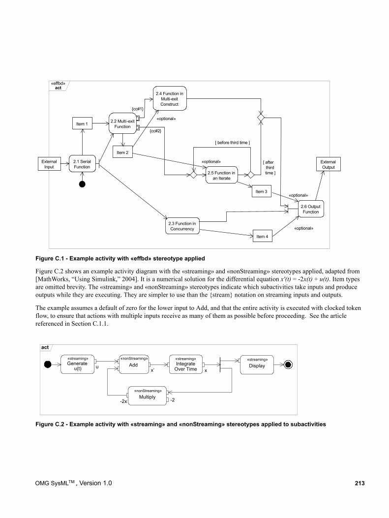
Figure C.1 - Example activity with «effbd» stereotype applied
Figure C.2 shows an example activity diagram with the «streaming» and «nonStreaming» stereotypes applied, adapted from [MathWorks, “Using Simulink,” 2004]. It is a numerical solution for the differential equation x'(t) = -2x(t) + u(t). Item types are omitted brevity. The «streaming» and «nonStreaming» stereotypes indicate which subactivities take inputs and produce outputs while they are executing. They are simpler to use than the {stream} notation on streaming inputs and outputs.
The example assumes a default of zero for the lower input to Add, and that the entire activity is executed with clocked token flow, to ensure that actions with multiple inputs receive as many of them as possible before proceeding. See the article referenced in Section C.1.1.
Figure C.2 - Example activity with «streaming» and «nonStreaming» stereotypes applied to subactivities
ExternalInput
ExternalOutput
2.1 SerialFunction
2.2 Multi-exitFunction
2.3 Function inConcurrency
Item 1
2.4 Function inMulti-exitConstruct
2.5 Function inan Iterate
[ before third time ]
Item 2
«optional» [ afterthirdtime ]
2.6 OutputFunction
«optional»
Item 3
Item 4
«optional»
«optional»
{cc#1}
{cc#2}
«effbd»act
Generateu(t)
Add
-2
Display«streaming»
IntegrateOver Timeu
x’ x
Multiply-2x
«nonStreaming» «streaming» «streaming»
«nonStreaming»
act
OMG SysMLTM , Version 1.0 213
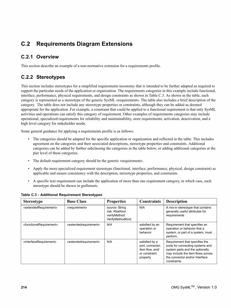
C.2 Requirements Diagram Extensions
C.2.1 OverviewThis section describe an example of a non-normative extension for a requirements profile.
C.2.2 StereotypesThis section includes stereotypes for a simplified requirements taxonomy that is intended to be further adapted as required to support the particular needs of the application or organization. The requirements categories in this example include functional, interface, performance, physical requirements, and design constraints as shown in Table C.3. As shown in the table, each category is represented as a stereotype of the generic SysML «requirement». The table also includes a brief description of the category. The table does not include any stereotype properties or constraints, although they can be added as deemed appropriate for the application. For example, a constraint that could be applied to a functional requirement is that only SysML activities and operations can satisfy this category of requirement. Other examples of requirements categories may include operational, specialized requirements for reliability and maintainability, store requirements, activation, deactivation, and a high level category for stakeholder needs.
Some general guidance for applying a requirements profile is as follows:
• The categories should be adapted for the specific application or organization and reflected in the table. This includes agreement on the categories and their associated descriptions, stereotype properties and constraints. Additional categories can be added by further subclassing the categories in the table below, or adding additional categories at the pier level of these categories.
• The default requirement category should be the generic «requirement».
• Apply the more specialized requirement stereotype (functional, interface, performance, physical, design constraint) as applicable and ensure consistency with the description, stereotype properties, and constraints.
• A specific text requirement can include the application of more than one requirement category, in which case, each stereotype should be shown in guillemets.
Table C.3 - Additional Requirement Stereotypes
Stereotype Base Class Properties Constraints Description«extendedRequirement» «requirement» source: String
risk: RiskKindverifyMethod: VerifyMethodKind
N/A A mix-in stereotype that contains generally useful attributes for requirements
«functionalRequirement» «extendedrequirement» N/A satisfied by an operation or behavior
Requirement that specifies an operation or behavior that a system, or part of a system, must perform.
«interfaceRequirement» «extendedrequirement» N/A satisfied by a port, connector, item flow, and/or constraint property
Requirement that specifies the ports for connecting systems and system parts and the optionally may include the item flows across the connector and/or Interface constraints.
214 OMG SysMLTM , Version 1.0
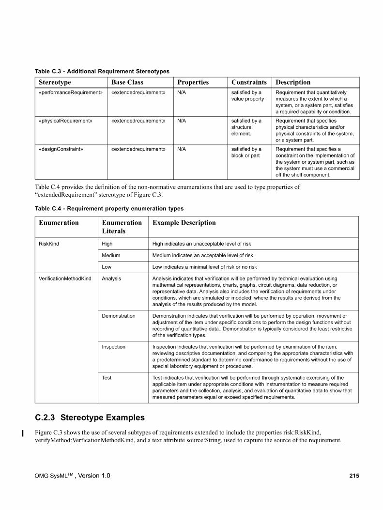
Table C.4 provides the definition of the non-normative enumerations that are used to type properties of “extendedRequirement” stereotype of Figure C.3.
C.2.3 Stereotype ExamplesFigure C.3 shows the use of several subtypes of requirements extended to include the properties risk:RiskKind, verifyMethod:VerficationMethodKind, and a text attribute source:String, used to capture the source of the requirement.
«performanceRequirement» «extendedrequirement» N/A satisfied by a value property
Requirement that quantitatively measures the extent to which a system, or a system part, satisfies a required capability or condition.
«physicalRequirement» «extendedrequirement» N/A satisfied by a structural element.
Requirement that specifies physical characteristics and/or physical constraints of the system, or a system part.
«designConstraint» «extendedrequirement» N/A satisfied by a block or part
Requirement that specifies a constraint on the implementation of the system or system part, such as the system must use a commercial off the shelf component.
Table C.4 - Requirement property enumeration types
Enumeration EnumerationLiterals
Example Description
RiskKind High High indicates an unacceptable level of risk
Medium Medium indicates an acceptable level of risk
Low Low indicates a minimal level of risk or no risk
VerificationMethodKind Analysis Analysis indicates that verification will be performed by technical evaluation using mathematical representations, charts, graphs, circuit diagrams, data reduction, or representative data. Analysis also includes the verification of requirements under conditions, which are simulated or modeled; where the results are derived from the analysis of the results produced by the model.
Demonstration Demonstration indicates that verification will be performed by operation, movement or adjustment of the item under specific conditions to perform the design functions without recording of quantitative data.. Demonstration is typically considered the least restrictive of the verification types.
Inspection Inspection indicates that verification will be performed by examination of the item, reviewing descriptive documentation, and comparing the appropriate characteristics with a predetermined standard to determine conformance to requirements without the use of special laboratory equipment or procedures.
Test Test indicates that verification will be performed through systematic exercising of the applicable item under appropriate conditions with instrumentation to measure required parameters and the collection, analysis, and evaluation of quantitative data to show that measured parameters equal or exceed specified requirements.
Table C.3 - Additional Requirement Stereotypes
Stereotype Base Class Properties Constraints Description
OMG SysMLTM , Version 1.0 215
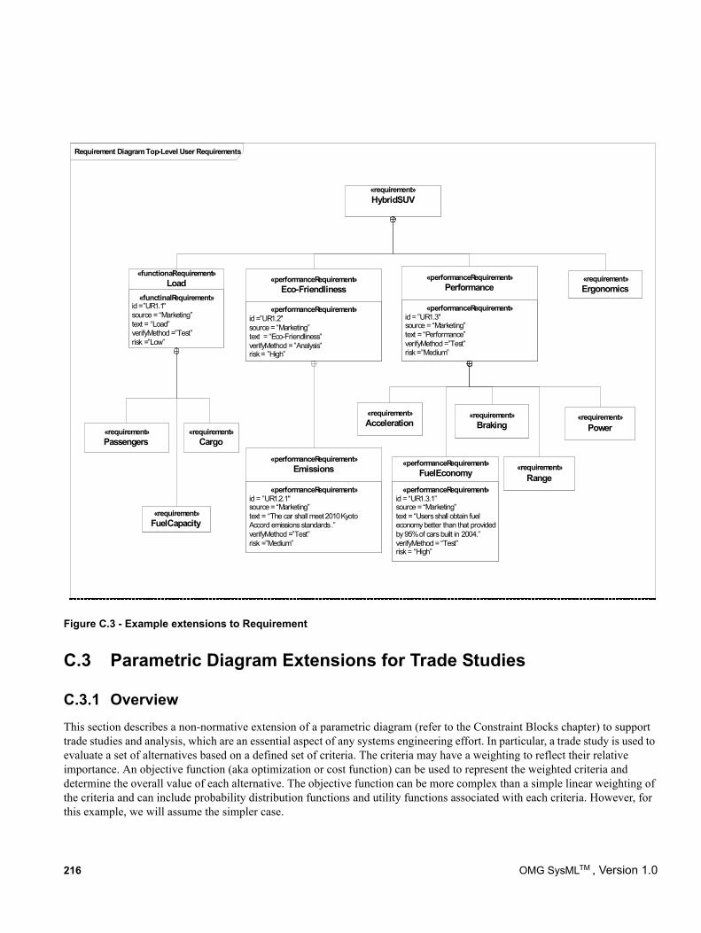
Figure C.3 - Example extensions to Requirement
C.3 Parametric Diagram Extensions for Trade Studies
C.3.1 OverviewThis section describes a non-normative extension of a parametric diagram (refer to the Constraint Blocks chapter) to support trade studies and analysis, which are an essential aspect of any systems engineering effort. In particular, a trade study is used to evaluate a set of alternatives based on a defined set of criteria. The criteria may have a weighting to reflect their relative importance. An objective function (aka optimization or cost function) can be used to represent the weighted criteria and determine the overall value of each alternative. The objective function can be more complex than a simple linear weighting of the criteria and can include probability distribution functions and utility functions associated with each criteria. However, for this example, we will assume the simpler case.
Requirement Diagram: Top-Level User Requirements
«requirement»HybridSUV
«functinalRequirement»id =”UR1.1"source = “Marketing”text = “Load”verifyMethod =”Test”risk =”Low”
«functionalRequirement»Load
«performanceRequirement»id =”UR1.2"source = “Marketing”text = “Eco-Friendliness”verifyMethod = ”Analysis”risk = ”High”
«performanceRequirement»Eco-Friendliness
«performanceRequirement»id = ”UR1.3"source = “Marketing”text = “Performance”verifyMethod =”Test”risk =”Medium”
«performanceRequirement»Performance
«requirement»Ergonomics
«requirement»Passengers
«requirement»Cargo
«requirement»FuelCapacity
«performanceRequirement»id = ”UR1.2.1"source = “Marketing”text = “The car shall meet 2010 Kyoto Accord emissions standards.”verifyMethod =”Test”risk =”Medium”
«performanceRequirement»Emissions
«performanceRequirement»id = “UR1.3.1”source = “Marketing”text = “Users shall obtain fuel economy better than that provided by 95% of cars built in 2004.”verifyMethod = “Test”risk = “High”
«performanceRequirement»FuelEconomy «requirement»
Range
«requirement»Braking
«requirement»Power
«requirement»Acceleration
216 OMG SysMLTM , Version 1.0
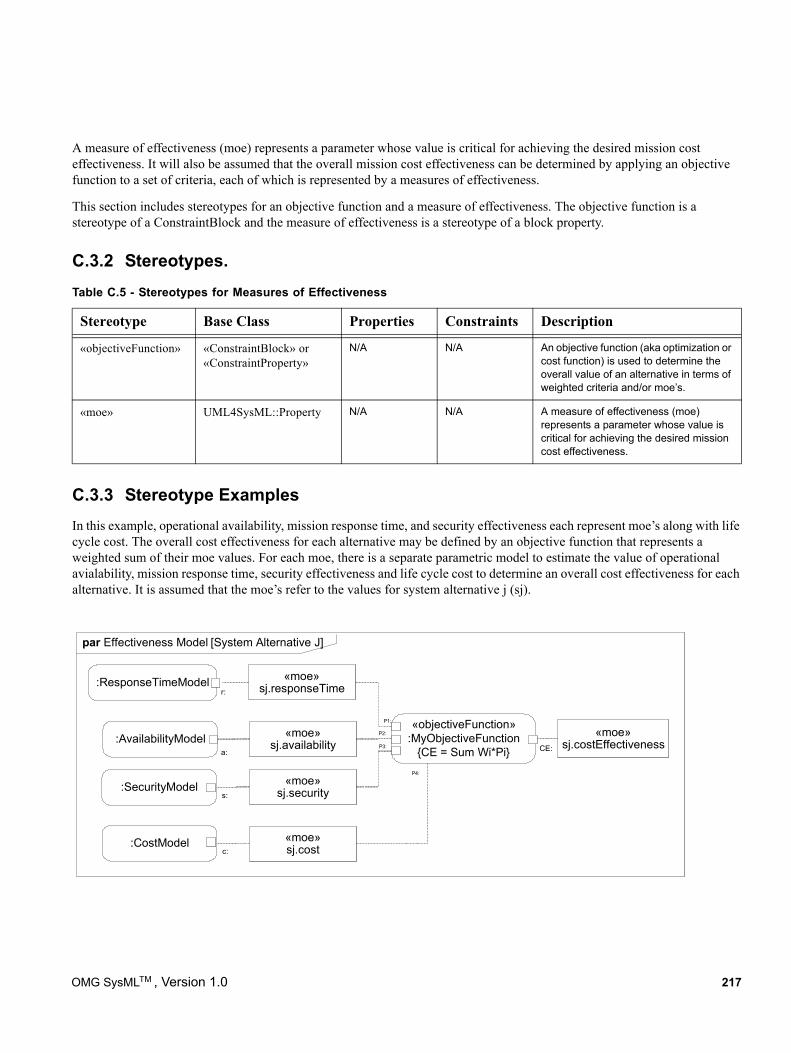
A measure of effectiveness (moe) represents a parameter whose value is critical for achieving the desired mission cost effectiveness. It will also be assumed that the overall mission cost effectiveness can be determined by applying an objective function to a set of criteria, each of which is represented by a measures of effectiveness.
This section includes stereotypes for an objective function and a measure of effectiveness. The objective function is a stereotype of a ConstraintBlock and the measure of effectiveness is a stereotype of a block property.
C.3.2 Stereotypes.
N/A N/A An objective function (aka optimization or cost function) is used to determine the overall value of an alternative in terms of weighted criteria and/or moe’s.
N/A N/A A measure of effectiveness (moe) represents a parameter whose value is critical for achieving the desired mission cost effectiveness.
C.3.3 Stereotype ExamplesIn this example, operational availability, mission response time, and security effectiveness each represent moe’s along with life cycle cost. The overall cost effectiveness for each alternative may be defined by an objective function that represents a weighted sum of their moe values. For each moe, there is a separate parametric model to estimate the value of operational avialability, mission response time, security effectiveness and life cycle cost to determine an overall cost effectiveness for each alternative. It is assumed that the moe’s refer to the values for system alternative j (sj).
Table C.5 - Stereotypes for Measures of Effectiveness
Stereotype Base Class Properties Constraints Description
«objectiveFunction» «ConstraintBlock» or «ConstraintProperty»
«moe» UML4SysML::Property
«moe»sj.costEffectiveness
par Effectiveness Model [System Alternative J]
:SecurityModel
«objectiveFunction»:MyObjectiveFunction
{CE = Sum Wi*Pi}
:ResponseTimeModel
:AvailabilityModelCE:P3:
P2:
P1:
s:
r:
a:
:CostModelc:
P4:
«moe»sj.responseTime
«moe»sj.security
«moe»sj.cost
«moe»sj.availability
OMG SysMLTM , Version 1.0 217
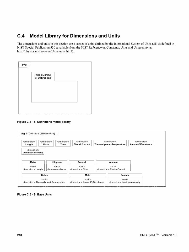
C.4 Model Library for Dimensions and UnitsThe dimensions and units in this section are a subset of units defined by the International System of Units (SI) as defined in NIST Special Publication 330 (available from the NIST Reference on Constants, Units and Uncertainty at http://physics.nist.gov/cuu/Units/units.html)..
Figure C.4 - SI Definitions model library
Figure C.5 - SI Base Units
pkg
«modelLibrary»SI Definitions
pkg SI Definitions [SI Base Units]
«dimension»Length
«dimension»Mass
«dimension»Time
«dimension»ElectricCurrent
«dimension»ThermodynamicTemperature
«dimension»AmountOfSubstance
«dimension»LuminousIntensity
«unit»dimension = Length
Meter
«unit»dimension = Mass
Kilogram
«unit»dimension = Time
Second
«unit»dimension = ElectricCurrent
Ampere
«unit»dimension = ThermodynamicTemperature
Kelvin
«unit»dimension = AmountOfSubstance
Mole
«unit»dimension = LuminousIntensity
Candela
218 OMG SysMLTM , Version 1.0
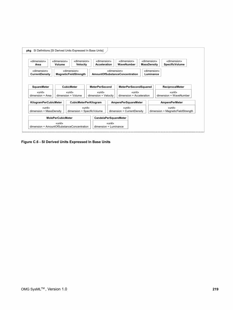
Figure C.6 - SI Derived Units Expressed In Base Units
pkg SI Definitions [SI Derived Units Expressed In Base Units]
«dimension»Area
«dimension»WaveNumber
«dimension»Volume
«dimension»Acceleration
«dimension»CurrentDensity
«dimension»MassDensity
«dimension»SpecificVolume
«dimension»MagneticFieldStrength
«dimension»AmountOfSubstanceConcentration
«dimension»Velocity
«dimension»Luminance
«unit»dimension = Area
SquareMeter
«unit»dimension = Acceleration
MeterPerSecondSquared
«unit»dimension = Volume
CubicMeter
«unit»dimension = WaveNumber
ReciprocalMeter
«unit»dimension = MagneticFieldStrength
AmperePerMeter
«unit»dimension = Velocity
MeterPerSecond
«unit»dimension = AmountOfSubstanceConcentration
MolePerCubicMeter
«unit»dimension = MassDensity
KilogramPerCubicMeter
«unit»dimension = SpecificVolume
CubicMeterPerKilogram
«unit»dimension = CurrentDensity
AmperePerSquareMeter
«unit»dimension = Luminance
CandelaPerSquareMeter
OMG SysMLTM , Version 1.0 219
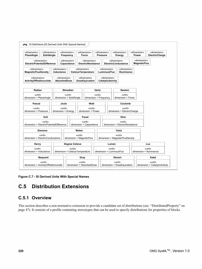
C.5 Distribution Extensions
C.5.1 Overview This section describes a non-normative extension to provide a candidate set of distributions (see “DistributedProperty” on page 47). It consists of a profile containing stereotypes that can be used to specify distributions for properties of blocks.
Figure C.7 - SI Derived Units With Special Names
pkg SI Definitions [SI Derived Units With Special Names]
«dimension»PlaneAngle
«dimension»SolidAngle
«dimension»Pressure
«dimension»Energy
«dimension»Power
«dimension»Force
«dimension»Frequency
«dimension»ElectricCharge
«dimension»ElectricPotentialDifference
«dimension»Capacitance
«dimension»ElectricResistance
«dimension»ElectricConductance
«dimension»MagneticFlux
«dimension»MagneticFluxDensity
«dimension»CelsiusTemperature
«dimension»LuminousFlux
«dimension»Inductance
«dimension»Illuminance
«dimension»CatalyticActivity
«dimension»DoseEquivalent
«dimension»AbsorbedDose
«dimension»ActivityOfRadionuclide
«unit»dimension = ElectricConductance
Siemens
«unit»dimension = PlaneAngle
Radian
«unit»dimension = SolidAngle
Steradian
«unit»dimension = Frequency
Hertz
«unit»dimension = Force
Newton
«unit»dimension = Pressure
Pascal
«unit»dimension = Energy
Joule
«unit»dimension = Power
Watt
«unit»dimension = ElectricCharge
Coulomb
«unit»dimension = ElectricPotentialDifference
Volt
«unit»dimension = Capacitance
Farad
«unit»dimension = ElectricResistance
Ohm
«unit»dimension = MagneticFlux
Weber
«unit»dimension = MagneticFluxDensity
Tesla
«unit»dimension = Inductance
Henry
«unit»dimension = CelsiusTemperature
Degree Celsius
«unit»dimension = LuminousFlux
Lumen
«unit»dimension = Illuminance
Lux
«unit»dimension = ActivityOfRadionuclide
Bequerel
«unit»dimension = AbsorbedDose
Gray
«unit»dimension = DoseEquivalent
Sievert
«unit»dimension = CatalyticActivity
Katal
220 OMG SysMLTM , Version 1.0
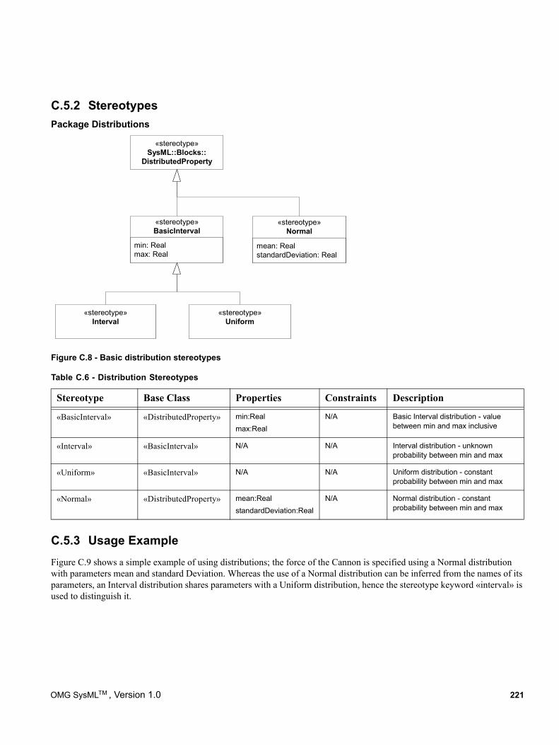
C.5.2 StereotypesPackage Distributions
«stereotype»Uniform
«stereotype»Interval
min: Realmax: Real
«stereotype»BasicInterval
mean: RealstandardDeviation: Real
«stereotype»Normal
«stereotype»SysML::Blocks::
DistributedProperty
Figure C.8 - Basic distribution stereotypes
C.5.3 Usage ExampleFigure C.9 shows a simple example of using distributions; the force of the Cannon is specified using a Normal distribution with parameters mean and standard Deviation. Whereas the use of a Normal distribution can be inferred from the names of its parameters, an Interval distribution shares parameters with a Uniform distribution, hence the stereotype keyword «interval» is used to distinguish it.
Table C.6 - Distribution Stereotypes
Stereotype Base Class Properties Constraints Description
«BasicInterval» «DistributedProperty» min:Realmax:Real
N/A Basic Interval distribution - value between min and max inclusive
«Interval» «BasicInterval» N/A N/A Interval distribution - unknown probability between min and max
«Uniform» «BasicInterval» N/A N/A Uniform distribution - constant probability between min and max
«Normal» «DistributedProperty» mean:RealstandardDeviation:Real
N/A Normal distribution - constant probability between min and max
OMG SysMLTM , Version 1.0 221
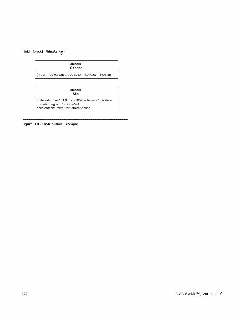
Figure C.9 - Distribution Example
bdd [block] FiringRange
{mean=100.0,standardDeviation=1.0}force: Newton
«block»Cannon
«interval»{min=101.0,max=105.0}volume: CubicMeterdensity:KilogramPerCubicMeteracceleration: MeterPerSquareSecond
«block»Shot
222 OMG SysMLTM , Version 1.0
Annex D: Model Interchange
(informative)
D.1 OverviewThis annex describes several methods for exchanging SysML models between tools. The first method discussed is XML Metadata Interchange (XMI), which is the preferred method for exchanging models between UML-based tools. The second approach describes the use of ISO 10303-233 Application Protocol: Systems engineering and design (AP233), which is one of the series of STEP (Standard for the Exchange of Product Model Data) neutral data schemas for representing engineering data. Other model interchange approaches are possible, but the ones described in this annex are expected to be the primary ones supported by SysML.
D.2 Context for Model InterchangeDeveloping today’s complex systems typically requires engineering teams that are distributed in time and space and that are often composed of many companies, each with their own culture, methods and tools. Effective collaboration requires agreement on, and a thorough understanding of, the various work assignments and resulting artifacts.
Many of these artifacts pertain to shared engineering data (e.g., requirements, system structural and behavioral models, verification & validation) that transcend the entire life cycle of the system of interest and are the basis for important systems engineering considerations and decisions. So it is critical that the system information contained in these artifacts and information models be accurately captured and readable by all appropriate team members in a timely manner.
Today, this information resides in an array of tools where each is only concerned with a portion of systems engineering data and can’t share its data with other tools because they only understand their own native schema. To mitigate this situation, collaborating organizations are usually forced to either adopt a common set of tools or develop a unique, bidirectional interface between many of the tools that each organization uses. This can be an expensive and untimely approach to data exchange between team members. So there is a need to define standardized approaches for model interchange between the different data schemas in use.
D.3 XMI Serialization of SysMLUML 2.0 is formally defined using the OMG Meta Object Facility (MOF). MOF can be considered a language for specifying modeling languages. The OMG XML Metadata Interchange (XMI) 2.1 standard specifies an XML-based interchange format for any language modeled using MOF. This results in a standard, convenient format for serializing UML user models as XMI files for interchange between UML tools. The XMI specification also includes rules for generating an XML Schema that can be used for basic validation of the structure of those UML user model XMI files.
The UML language includes an extension mechanism called UML Profiles. UML Profiles are themselves defined as UML models (MOF is not used). However, their intent is to specify extensions to the UML language semantics in much the same way one could extend the UML language by adding to the MOF definition of UML. As UML Profiles are valid UML models, XMI does provide a mechanism for exchanging the UML Profiles between UML tools. However, as they are extensions to concepts defined in the UML language itself, the definition of a UML Profile refers to the UML language definitions. An XMI 2.1 representation of the SysML profile (i.e., the UML Profile for SysML), as well as XMI 2.1 representations of Model Libraries defined by SysML, are provided as support documents to this specification. As with UML, XMI provides a
OMG SysMLTM , Version 1.0 223
convenient serialized format for model interchange between SysML tools and basic validation of those files using an XML Schema as well.
D.4 Overview of ISO 10303-233 STEP AP233AP233 is not finalized at this time, so this section reflects the background and current status of the AP233 work.
AP233 is a neutral data schema for representing systems engineering data. AP233 is being standardized under the ISO TC-184 (Technical Committee on Industrial Automation Systems and Integration), SC4 (Subcommittee on Industrial Data Standards), and is part of the larger STEP effort, which provides standardized models and infrastructure for the exchange of product model data.
D.4.1 Scope of ISO 10303-233 STEP AP233AP233 will include support for describing:
• requirement
• functional
• structure
• physical structure & allocation
• configuration & traceability
• project & data management
An IDEF activity that shows the scope of AP233 information requirements is available at http://www.ap233.org/ap233-public-information/AAM_AP233-Issue-1.pdf/view. Additional details on AP233 can be found at http://www.ap233.org/.
D.4.2 ISO 10303-233 STEP AP233 Development Approach & StatusAP233 and several other STEP application protocols are being built using a modular architecture. This enables the same information model to be reused across disciplines and life cycle stages. In the STEP Modular Architecture these reusable information models are called application modules, or more informally simply modules. AP233 will consist of a number of modules that together will satisfy the scope of the requirements stated above. Support for several of systems engineering viewpoints within the scope of AP233 already exist as the result of the development of other application protocols and will simply be reused in AP233. When existing STEP modules do not provide needed capabilities, new modules are being defined as part of AP233 development. Since AP233 is part of STEP, it is easy to relate systems engineering data to that of other engineering disciplines over the lifecycle of a system and to related product models.
Figure D-1 provides an overview of the modules planned to satisfy the scope of AP233 requirements and also shows the current status of each.
224 OMG SysMLTM , Version 1.0
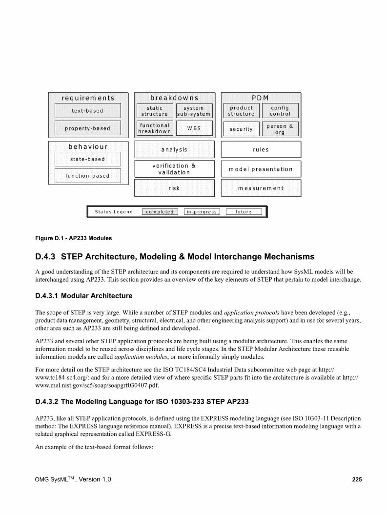
Figure D.1 - AP233 Modules
D.4.3 STEP Architecture, Modeling & Model Interchange MechanismsA good understanding of the STEP architecture and its components are required to understand how SysML models will be interchanged using AP233. This section provides an overview of the key elements of STEP that pertain to model interchange.
D.4.3.1 Modular Architecture
The scope of STEP is very large. While a number of STEP modules and application protocols have been developed (e.g., product data management, geometry, structural, electrical, and other engineering analysis support) and in use for several years, other area such as AP233 are still being defined and developed.
AP233 and several other STEP application protocols are being built using a modular architecture. This enables the same information model to be reused across disciplines and life cycle stages. In the STEP Modular Architecture these reusable information models are called application modules, or more informally simply modules.
For more detail on the STEP architecture see the ISO TC184/SC4 Industrial Data subcommittee web page at http://www.tc184-sc4.org/: and for a more detailed view of where specific STEP parts fit into the architecture is available at http://www.mel.nist.gov/sc5/soap/soapgrf030407.pdf.
D.4.3.2 The Modeling Language for ISO 10303-233 STEP AP233
AP233, like all STEP application protocols, is defined using the EXPRESS modeling language (see ISO 10303-11 Description method: The EXPRESS language reference manual). EXPRESS is a precise text-based information modeling language with a related graphical representation called EXPRESS-G.
An example of the text-based format follows:
r e q u ire m e n ts
te x t -b a s e d
p ro p e r ty -b a s e d
b re a k d o w n ss ta t ic
s t ru c tu re
P D M
a n a ly s is ru le sb e h a v io u r
p ro d u c ts t ru c tu re
s y s te ms u b -s y s te m
fu n c t io n a lb re a k d o w n W B S
v e r if ic a t io n &v a lid a t io n
s ta te -b a s e d
fu n c t io n -b a s e dm o d e l p re s e n ta t io n
c o n f igc o n tro l
s e c u r ity
r is kr is k m e a s u re m e n t
p e rs o n &o rg
c o m p le te d in - p ro g re s sS ta tu s L e g e n d fu tu re
OMG SysMLTM , Version 1.0 225
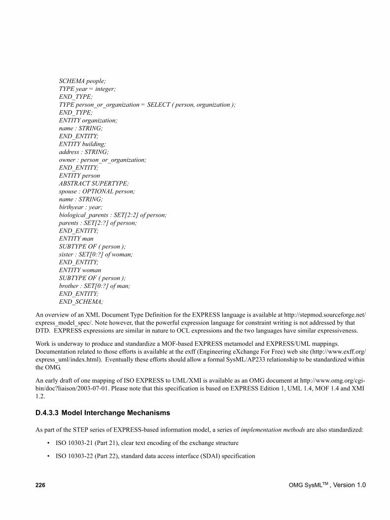
SCHEMA people; TYPE year = integer;END_TYPE;TYPE person_or_organization = SELECT ( person, organization );END_TYPE;ENTITY organization;name : STRING;END_ENTITY;ENTITY building;address : STRING;owner : person_or_organization;END_ENTITY;ENTITY personABSTRACT SUPERTYPE;spouse : OPTIONAL person;name : STRING;birthyear : year;biological_parents : SET[2:2] of person;parents : SET[2:?] of person;END_ENTITY;ENTITY manSUBTYPE OF ( person );sister : SET[0:?] of woman;END_ENTITY;ENTITY womanSUBTYPE OF ( person );brother : SET[0:?] of man;END_ENTITY;END_SCHEMA;
An overview of an XML Document Type Definition for the EXPRESS language is available at http://stepmod.sourceforge.net/express_model_spec/. Note however, that the powerful expression language for constraint writing is not addressed by that DTD. EXPRESS expressions are similar in nature to OCL expressions and the two languages have similar expressiveness.
Work is underway to produce and standardize a MOF-based EXPRESS metamodel and EXPRESS/UML mappings. Documentation related to those efforts is available at the exff (Engineering eXchange For Free) web site (http://www.exff.org/express_uml/index.html). Eventually these efforts should allow a formal SysML/AP233 relationship to be standardized within the OMG.
An early draft of one mapping of ISO EXPRESS to UML/XMI is available as an OMG document at http://www.omg.org/cgi-bin/doc?liaison/2003-07-01. Please note that this specification is based on EXPRESS Edition 1, UML 1.4, MOF 1.4 and XMI 1.2.
D.4.3.3 Model Interchange Mechanisms
As part of the STEP series of EXPRESS-based information model, a series of implementation methods are also standardized:
• ISO 10303-21 (Part 21), clear text encoding of the exchange structure
• ISO 10303-22 (Part 22), standard data access interface (SDAI) specification
226 OMG SysMLTM , Version 1.0
• ISO 10303-25 (Part 25), EXPRESS to OMG XMI binding
• ISO 10303-28 (Part 28), XML representation of EXPRESS schemas and data
A conforming STEP implementation is the combination of a STEP application protocol and one or more of the implementation methods.
SDAI specifies a standard programming interface for access to EXPRESS-based data. SDAI allows the implementors to refer to product data in terms of its conceptual EXPRESS definitions, regardless of the underlying data structure or storage technology. Bindings of the SDAI to C++ (ISO 10303-23), C (ISO 10303-24), Java (ISO 10303-27) provide standardized APIs for accessing EXPRESS-based data.
D.4.4 ISO 10303-233 STEP AP233 - SysML Alignment & Mapping ModelThe requirements for AP233 and SysML have been largely aligned by the OMG and the ISO teams working together and in close cooperation with the INCOSE Model Driven System Design working group. However, there might be differences in breadth and scope of AP233 and SysML resulting from the different development life cycles of both activities and the different nature of the modeling frameworks used to define SysML and AP233. To avoid semantic issues in exchanging data between SysML and AP233, a neutral mapping model of systems engineering concepts will be defined. Thus the mappings between the mapping model and SysML metamodel and the mapping model and AP233 metamodel can be maintained independently. The neutral mapping model will also help to clarify the semantics of the data elements. This approach is illustrated in Figure D-2.
As AP233 and SysML are defined in different modeling frameworks, the AP233 metamodel will be converted to UML to ease the mapping. OMG has started a standardization activity to capture EXPRESS semantics in UML, but a custom mapping will be used until the UML profile for EXPRESS has been adopted. The mapping model will be expressed as a plain MOF model. The mapping model will be defined based on the concepts used and implemented for AP233 and SysML. Another important input is the conceptual systems engineering model maintained by the INCOSE Model Driven System Design Working group. Since development of the mapping model and SysML and AP233 mappings to it is an ongoing maintenance activity, these specifications will be maintained separately and updates will be posted on the SE DSIG web site.
The mapping model can be used as the basis for the model-exchange methods discussed in the next section and also for the development of conceptual level APIs, which should ease the usage of AP233 and generation of common test cases for SysML and AP233.
OMG SysMLTM , Version 1.0 227
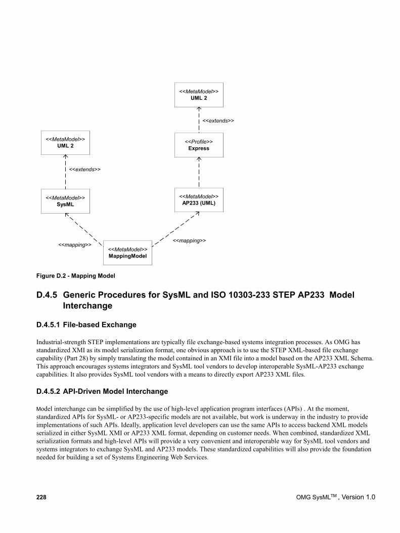
Figure D.2 - Mapping Model
D.4.5 Generic Procedures for SysML and ISO 10303-233 STEP AP233 Model Interchange
D.4.5.1 File-based Exchange
Industrial-strength STEP implementations are typically file exchange-based systems integration processes. As OMG has standardized XMI as its model serialization format, one obvious approach is to use the STEP XML-based file exchange capability (Part 28) by simply translating the model contained in an XMI file into a model based on the AP233 XML Schema. This approach encourages systems integrators and SysML tool vendors to develop interoperable SysML-AP233 exchange capabilities. It also provides SysML tool vendors with a means to directly export AP233 XML files.
D.4.5.2 API-Driven Model Interchange
Model interchange can be simplified by the use of high-level application program interfaces (APIs) . At the moment, standardized APIs for SysML- or AP233-specific models are not available, but work is underway in the industry to provide implementations of such APIs. Ideally, application level developers can use the same APIs to access backend XML models serialized in either SysML XMI or AP233 XML format, depending on customer needs. When combined, standardized XML serialization formats and high-level APIs will provide a very convenient and interoperable way for SysML tool vendors and systems integrators to exchange SysML and AP233 models. These standardized capabilities will also provide the foundation needed for building a set of Systems Engineering Web Services.
<<MetaModel>>UML 2
<<MetaModel>>SysML
<<MetaModel>>MappingModel
<<Profile>>Express
<<MetaModel>>UML 2
<<MetaModel>>AP233 (UML)
<<extends>>
<<extends>>
<<mapping>><<mapping>>
228 OMG SysMLTM , Version 1.0
Annex E: Requirements Traceability
The OMG SysML requirements traceability matrix traces this specification to the original source requirements in the UML for Systems Engineering RFP (ad/2003-03-41). The traceability matrix is included by reference in a separate document (ptc/2007-03-09).
OMG SysMLTM , Version 1.0 229

230 OMG SysMLTM , Version 1.0
Annex F: Terms and Definitions
(informative)
The SysML glossary is included as a support document ad/2006-03-04 to this specification. The terms and definitions are referred to in the SysML specification and are derived from multiple sources including the UML 2.1 Superstructure specifica-tion and the UML for Systems Engineering RFP (ad/2003-03-41).
OMG SysMLTM , Version 1.0 231

232 OMG SysMLTM , Version 1.0
INDEX
AActions 9, 13, 14Activities 9, 13, 14, 15activity diagram 172Allocation 129allocation tables 172Allocations 15Architecture 7, 8Attributes 27
BBinding Connector 44Block 44
labeled compartments 38Block definition diagram 19, 38, 172Blocks 15, 19, 31, 65
contraints compartment 39definitions 38diagram elements 32internal block diagram 37, 40namespace compartment 39overview 31structure compartment 39valuetypes 38
CClasses 9, 13, 14Comments 21
note box 25compartments 38Complex number 50Compliance 13, 15
abstract syntax 15concrete syntax 15levels 13
ConnectorProperty 46constraint 39Constraint blocks 15, 19, 75, 79constraint property 79Constraints 21, 26, 27Constructs 19
DDesign principles 7Diagrams 11, 19, 171
elements 17extensions 25
Dimension 47DistributedProperty 47
EElements 17, 24Extensions 14, 25
UMLextensions 18
FFeature support statements 16FlowPort 59, 63, 66FlowProperty 63, 67Flows 15, 19, 59FlowSpecification 64, 68Formalism 17
levels 17
GGeneral behavior 9, 13
IIcons 25IEEE 1471 standard 21Information flows 9, 14Interactions 9, 13Internal block diagram 19, 40, 172Interoperability 8Item Flow 59, 64ItemFlow 68
KKeywords 25
LLanguages 7
formalism 17SysML 7UML 7, 9
Layering 8Library models 10
MMetaclasses 8Model Libraries 50Model library 101, 157Models 9, 14
elements 15, 19, 21libraries 10
Nnamespace compartment 39NestedConnectorEnd stereotype 47
PPackage diagrams 19, 172Parametric diagrams 19, 172ParticipantProperty 48Partioning 8Ports 15, 19, 59
flow 59standard 59
Problem description 26Profiles 9, 14
SysML 8, 10Profiles package 157property 31property path name 41PropertySpecificType 48
RRationale description 26
OMG SysMLTM, Version 1.0 233
Real number 50Realization
full 15Relationships
conform 26Requirements 7, 15, 141Requirements diagram 172Reuse 8
SSequence diagram 172Standard Port 59State machine diagram 172State machines 9, 14StateMachine 115stereotype keyword 38Stereotypes 10, 43
keywords 25Structural Constructs 19Structure
chapter specification 17structure compartment 39Structures 9, 13, 14Syntax 15
concrete 17SysML 7
compliance 13, 14design principles 7diagrams 11examples 18extensions 10, 14extensions to UML 7modeling constructs 17packages 10profile 8, 10reuse 8UML elements not included in 25
SysML blocks 31SysML diagrams 171SysML ValueType 38Systems engineering 18
UUML
diagram extensions 10elements not in SysML 25extensions for SysML 7, 10language units 9stereotypes 10
Unit 49Use case diagram 172Use cases 9, 13, 121
VValueType 38, 49Viewpoint description 27
XXML Metadata Interchange (XMI) 223
234 OMG SysMLTM, Version 1.0


![Simulation-Based Design Using SysML - Part 2: Celebrating ...austin/enes489p/lecture-resources/SysML-Simulation-Part2...[OMG, 2007a] and COBs support engineering analysis templates](https://img.pdfslide.us/doc/110x75/5ecf4b86ef0e483c994b6a59/simulation-based-design-using-sysml-part-2-celebrating-austinenes489plecture-resourcessysml-simulation-part2.jpg)