Embed Size (px)
Citation preview
DAEWOOMY_2000
SECTION 1B3
OM600 ENGINE MECHANICAL
CAUTION: Disconnect the negative battery cable before removing or installing any electrical unit or when atool or equipment could easily come in contact with exposed electrical terminals. Disconnecting this cablewill help prevent personal injury and damage to the vehicle. The ignition must also be in LOCK unlessotherwise noted.
TABLE OF CONTENTSSpecifications 1B3--2. . . . . . . . . . . . . . . . . . . . . . . . . . . .
Fastener Tightening Specifications 1B3--2. . . . . . . . . .
Special Tools 1B3--4. . . . . . . . . . . . . . . . . . . . . . . . . . . . .
Special Tools Table 1B3--4. . . . . . . . . . . . . . . . . . . . . . .
Maintenance and Repair 1B3--12. . . . . . . . . . . . . . . . . .
On--Vehicle Service 1B3--12. . . . . . . . . . . . . . . . . . . . . . . .
Engine Assembly 1B3--12. . . . . . . . . . . . . . . . . . . . . . . .
Poly V--Belt 1B3--21. . . . . . . . . . . . . . . . . . . . . . . . . . . . .
Tensioning Device 1B3--23. . . . . . . . . . . . . . . . . . . . . . .
Poly V--Belt Alignment & Inspection 1B3--26. . . . . . . .
Prechamber 1B3--29. . . . . . . . . . . . . . . . . . . . . . . . . . . .
Milling of Prechamber Sealing Surface 1B3--32. . . . .
TDC (TDC Sensor Bracket) Setting 1B3--35. . . . . . . .
Cylinder Head 1B3--37. . . . . . . . . . . . . . . . . . . . . . . . . . .
Timing Case Cover 1B3--63. . . . . . . . . . . . . . . . . . . . . .
Crankshaft End Cover 1B3--71. . . . . . . . . . . . . . . . . . .
Vibration Damper and Hub 1B3--74. . . . . . . . . . . . . . .
Crankshaft Front Radial Seal 1B3--80. . . . . . . . . . . . .
Crankshaft Ball Bearing 1B3--82. . . . . . . . . . . . . . . . . .
Crankshaft 1B3--83. . . . . . . . . . . . . . . . . . . . . . . . . . . . .
Flywheel 1B3--93. . . . . . . . . . . . . . . . . . . . . . . . . . . . . . .
Machining of Flywheel 1B3--97. . . . . . . . . . . . . . . . . . .
Flywheel Ring Gear 1B3--98. . . . . . . . . . . . . . . . . . . . . .
Hydraulic Valve Clearance Compensation
Element Check 1B3--101. . . . . . . . . . . . . . . . . . . . . . . . .
Valve Tappets 1B3--103. . . . . . . . . . . . . . . . . . . . . . . . . .
Valve Spring Check 1B3--105. . . . . . . . . . . . . . . . . . . . .
Valve Springs (Cylinder Head Removed) 1B3--106. .
Valve Springs (Cylinder Head Installed) 1B3--109. . .
Valve Stem Seals 1B3--112. . . . . . . . . . . . . . . . . . . . . .
Check and Replacement of Valve Guides 1B3--116. .
Valve Seat Rings 1B3--122. . . . . . . . . . . . . . . . . . . . . . .
Check and Machining of Valves 1B3--127. . . . . . . . . .
Machining of Valve Seat 1B3--132. . . . . . . . . . . . . . . . .
Camshaft Timing Test 1B3--137. . . . . . . . . . . . . . . . . . .
Camshaft 1B3--139. . . . . . . . . . . . . . . . . . . . . . . . . . . . .
Chain Tensioner 1B3--145. . . . . . . . . . . . . . . . . . . . . . . .
Timing Chain 1B3--147. . . . . . . . . . . . . . . . . . . . . . . . . . .
Tensioning Rail 1B3--151. . . . . . . . . . . . . . . . . . . . . . . . .
Cylinder Head Guide Rail 1B3--152. . . . . . . . . . . . . . . .
Timing Case Cover Guide Rail 1B3--156. . . . . . . . . . .
Crankshaft Sprocket 1B3--158. . . . . . . . . . . . . . . . . . . .
Piston 1B3--163. . . . . . . . . . . . . . . . . . . . . . . . . . . . . . . . .
Oil Filter 1B3--169. . . . . . . . . . . . . . . . . . . . . . . . . . . . . . .
Oil Pan 1B3--171. . . . . . . . . . . . . . . . . . . . . . . . . . . . . . . .
Oil Spray Nozzle 1B3--174. . . . . . . . . . . . . . . . . . . . . . .
Oil Pump 1B3--175. . . . . . . . . . . . . . . . . . . . . . . . . . . . . .
Unit Repair 1B3--177. . . . . . . . . . . . . . . . . . . . . . . . . . . .
Cylinder Head Pressure Leakage Test 1B3--177. . . .
Facing Cylinder Head Mating Surface 1B3--178. . . . .
Replacement of Crankcase Core Plug 1B3--180. . . . .
Facing Crankcase Contacting Surface 1B3--182. . . .
Oil Gallery Steel Ball 1B3--183. . . . . . . . . . . . . . . . . . . .
Cylinder Bore Measurement 1B3--187. . . . . . . . . . . . .
1B3 -- 2 OM600 ENGINE MECHANICAL
DAEWOOMY_2000
SPECIFICATIONS
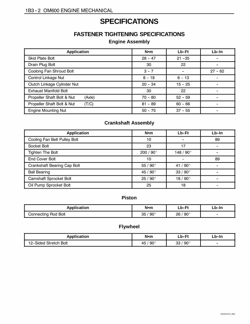
FASTENER TIGHTENING SPECIFICATIONSEngine Assembly
Application NSm Lb--Ft Lb--In
Skid Plate Bolt 28 -- 47 21 --35 --
Drain Plug Bolt 30 22 --
Coolong Fan Shroud Bolt 3 -- 7 -- 27 -- 62
Control Linkage Nut 8 -- 18 6 -- 13 --
Clutch Linkage Cylinder Nut 20 -- 34 15 -- 25 --
Exhaust Manifold Bolt 30 22 --
Propeller Shaft Bolt & Nut (Axle) 70 -- 80 52 -- 59 --
Propeller Shaft Bolt & Nut (T/C) 81 -- 89 60 -- 66 --
Engine Mounting Nut 50 -- 75 37 -- 55 --
Crankshaft Assembly
Application NSm Lb--Ft Lb--In
Cooling Fan Belt Pulley Bolt 10 -- 89
Socket Bolt 23 17 --
Tighten The Bolt 200 / 90_ 148 / 90_ --
End Cover Bolt 10 -- 89
Crankshaft Bearing Cap Bolt 55 / 90_ 41 / 90_ --
Ball Bearing 45 / 90_ 33 / 90_ --
Camshaft Sprocket Bolt 25 / 90_ 18 / 90_ --
Oil Pump Sprocket Bolt 25 18 --
Piston
Application NSm Lb--Ft Lb--In
Connecting Rod Bolt 35 / 90_ 26 / 90_ --
Flywheel
Application NSm Lb--Ft Lb--In
12--Sided Stretch Bolt 45 / 90_ 33 / 90_ --
OM600 ENGINE MECHANICAL 1B3 -- 3
DAEWOOMY_2000
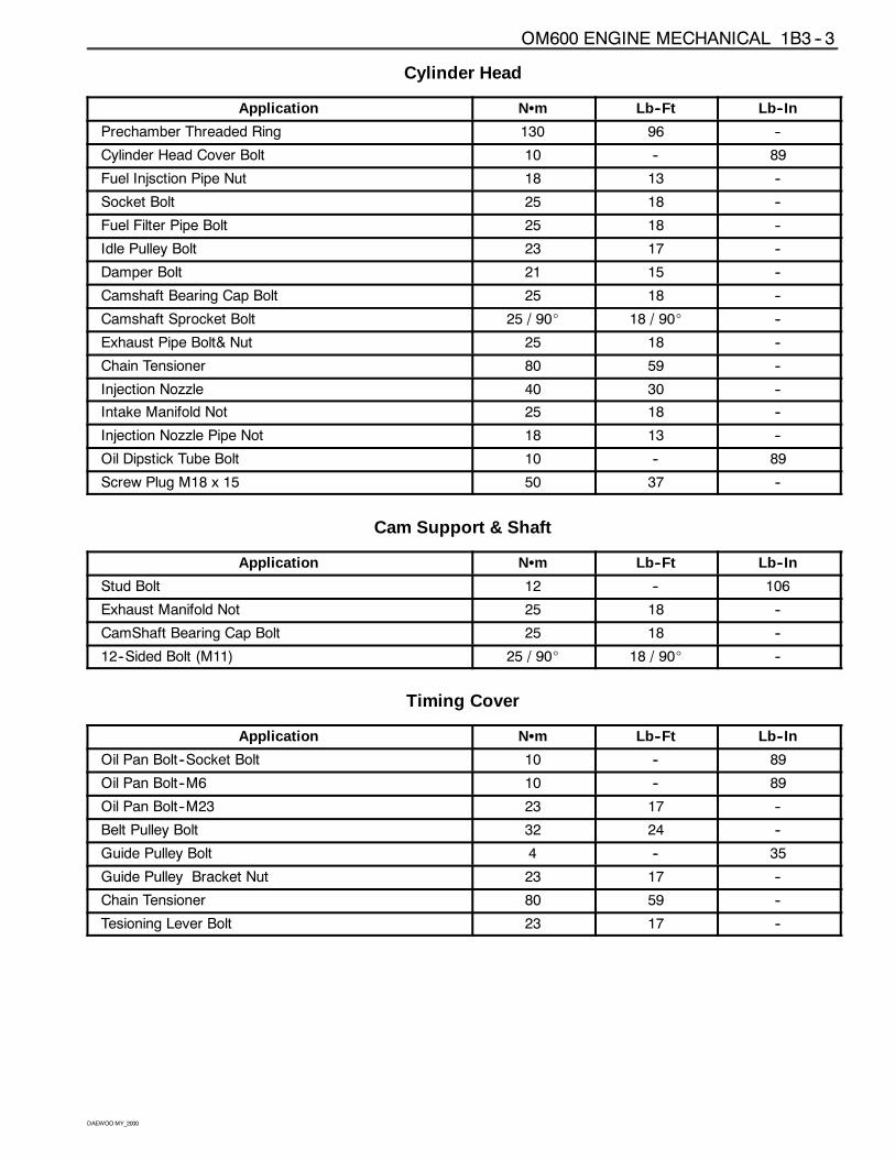
Cylinder Head
Application NSm Lb--Ft Lb--In
Prechamber Threaded Ring 130 96 --
Cylinder Head Cover Bolt 10 -- 89
Fuel Injsction Pipe Nut 18 13 --
Socket Bolt 25 18 --
Fuel Filter Pipe Bolt 25 18 --
Idle Pulley Bolt 23 17 --
Damper Bolt 21 15 --
Camshaft Bearing Cap Bolt 25 18 --
Camshaft Sprocket Bolt 25 / 90_ 18 / 90_ --
Exhaust Pipe Bolt& Nut 25 18 --
Chain Tensioner 80 59 --
Injection Nozzle 40 30 --
Intake Manifold Not 25 18 --
Injection Nozzle Pipe Not 18 13 --
Oil Dipstick Tube Bolt 10 -- 89
Screw Plug M18 x 15 50 37 --
Cam Support & Shaft
Application NSm Lb--Ft Lb--In
Stud Bolt 12 -- 106
Exhaust Manifold Not 25 18 --
CamShaft Bearing Cap Bolt 25 18 --
12--Sided Bolt (M11) 25 / 90_ 18 / 90_ --
Timing Cover
Application NSm Lb--Ft Lb--In
Oil Pan Bolt--Socket Bolt 10 -- 89
Oil Pan Bolt--M6 10 -- 89
Oil Pan Bolt--M23 23 17 --
Belt Pulley Bolt 32 24 --
Guide Pulley Bolt 4 -- 35
Guide Pulley Bracket Nut 23 17 --
Chain Tensioner 80 59 --
Tesioning Lever Bolt 23 17 --
OM600 ENGINE MECHANICAL 1B3 -- 5
DAEWOOMY_2000
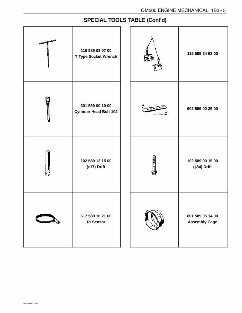
SPECIAL TOOLS TABLE (Cont’d)
116 589 03 07 00
T Type Socket Wrench
601 589 00 10 00
Cylinder Head Bolt 102
102 589 12 15 00
(φ17) Drift
617 589 10 21 00
RI Sensor
115 589 34 63 00
602 589 00 25 00
102 589 00 15 00
(φ34) Drift
601 589 05 14 00
Assembly Cage
1B3 -- 6 OM600 ENGINE MECHANICAL
DAEWOOMY_2000
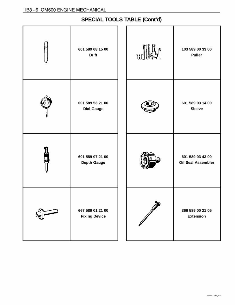
SPECIAL TOOLS TABLE (Cont’d)
601 589 08 15 00
Drift
001 589 53 21 00
Dial Gauge
601 589 07 21 00
Depth Gauge
667 589 01 21 00
Fixing Device
103 589 00 33 00
Puller
601 589 03 14 00
Sleeve
601 589 03 43 00
Oil Seal Assembler
366 589 00 21 05
Extension
OM600 ENGINE MECHANICAL 1B3 -- 7
DAEWOOMY_2000
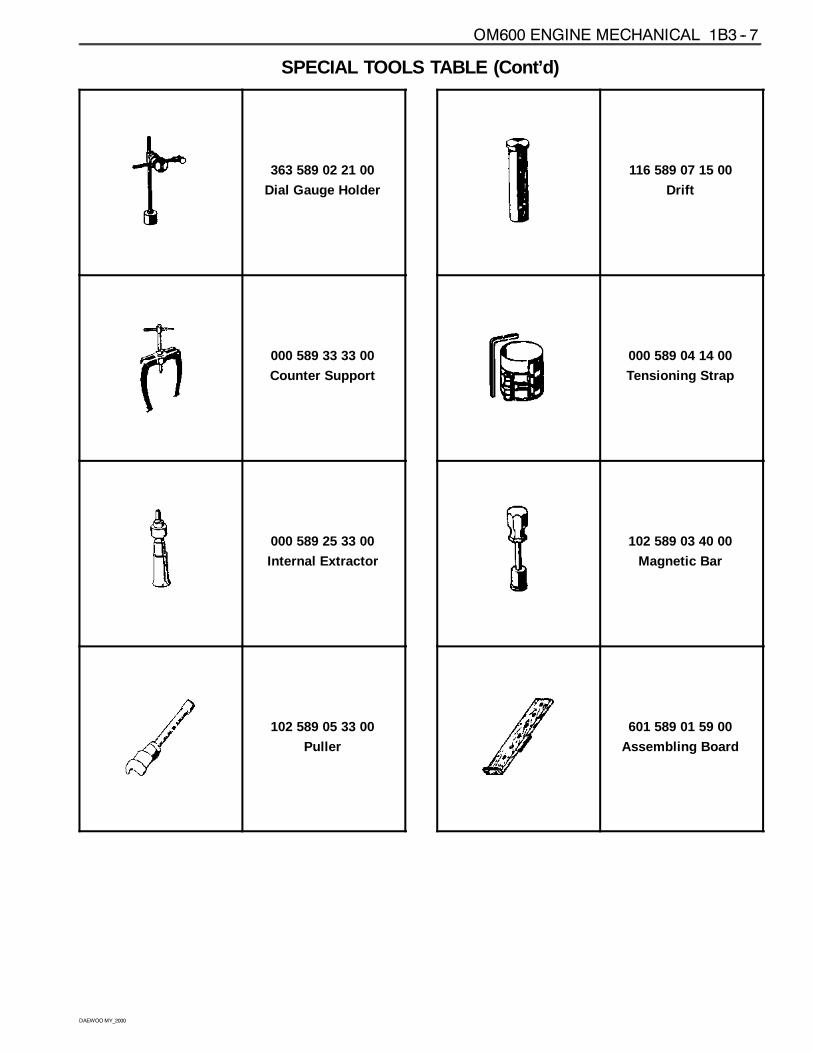
SPECIAL TOOLS TABLE (Cont’d)
363 589 02 21 00
Dial Gauge Holder
000 589 33 33 00
Counter Support
000 589 25 33 00
Internal Extractor
102 589 05 33 00
Puller
116 589 07 15 00
Drift
000 589 04 14 00
Tensioning Strap
102 589 03 40 00
Magnetic Bar
601 589 01 59 00
Assembling Board
1B3 -- 8 OM600 ENGINE MECHANICAL
DAEWOOMY_2000
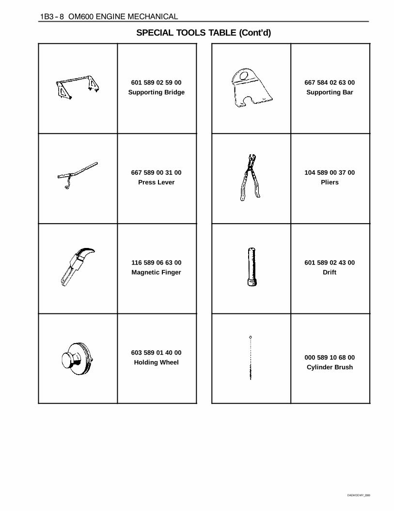
SPECIAL TOOLS TABLE (Cont’d)
601 589 02 59 00
Supporting Bridge
667 589 00 31 00
Press Lever
116 589 06 63 00
Magnetic Finger
603 589 01 40 00
Holding Wheel
667 584 02 63 00
Supporting Bar
104 589 00 37 00
Pliers
601 589 02 43 00
Drift
000 589 10 68 00
Cylinder Brush
OM600 ENGINE MECHANICAL 1B3 -- 9
DAEWOOMY_2000
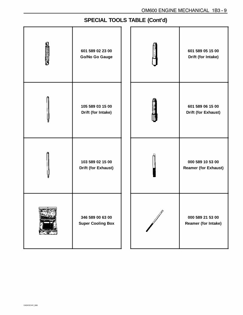
SPECIAL TOOLS TABLE (Cont’d)
601 589 02 23 00
Go/No Go Gauge
105 589 03 15 00
Drift (for Intake)
103 589 02 15 00
Drift (for Exhaust)
346 589 00 63 00
Super Cooling Box
601 589 05 15 00
Drift (for Intake)
601 589 06 15 00
Drift (for Exhaust)
000 589 10 53 00
Reamer (for Exhaust)
000 589 21 53 00
Reamer (for Intake)
1B3 -- 10 OM600 ENGINE MECHANICAL
DAEWOOMY_2000
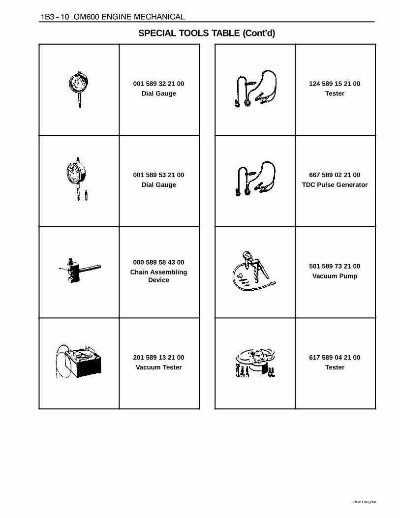
SPECIAL TOOLS TABLE (Cont’d)
001 589 32 21 00
Dial Gauge
001 589 53 21 00
Dial Gauge
000 589 58 43 00
Chain AssemblingDevice
201 589 13 21 00
Vacuum Tester
124 589 15 21 00
Tester
667 589 02 21 00
TDC Pulse Generator
501 589 73 21 00
Vacuum Pump
617 589 04 21 00
Tester
OM600 ENGINE MECHANICAL 1B3 -- 11
DAEWOOMY_2000
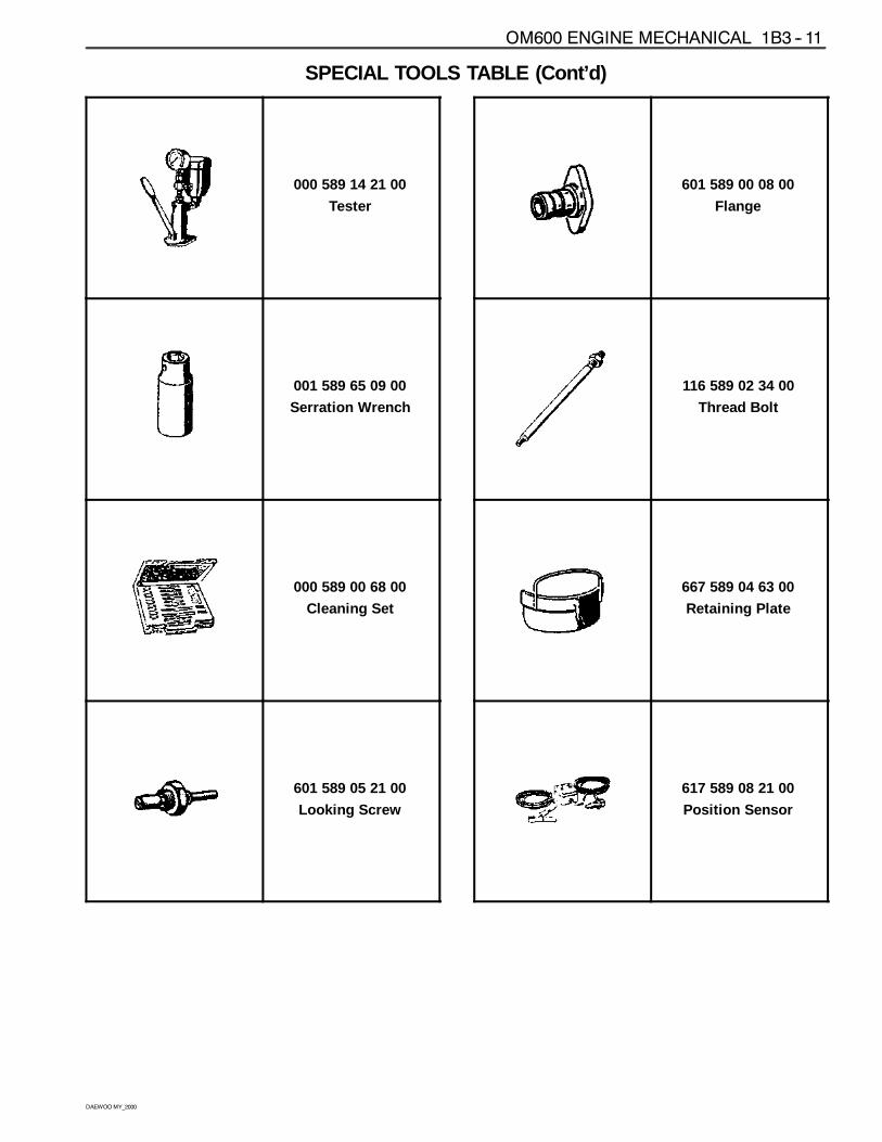
SPECIAL TOOLS TABLE (Cont’d)
000 589 14 21 00
Tester
001 589 65 09 00
Serration Wrench
000 589 00 68 00
Cleaning Set
601 589 05 21 00
Looking Screw
601 589 00 08 00
Flange
116 589 02 34 00
Thread Bolt
667 589 04 63 00
Retaining Plate
617 589 08 21 00
Position Sensor
1B3 -- 12 OM600 ENGINE MECHANICAL
DAEWOOMY_2000
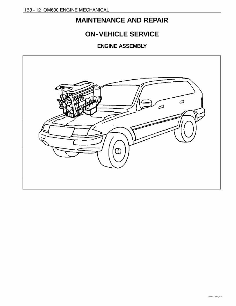
MAINTENANCE AND REPAIR
ON--VEHICLE SERVICE
ENGINE ASSEMBLY
OM600 ENGINE MECHANICAL 1B3 -- 13
DAEWOOMY_2000
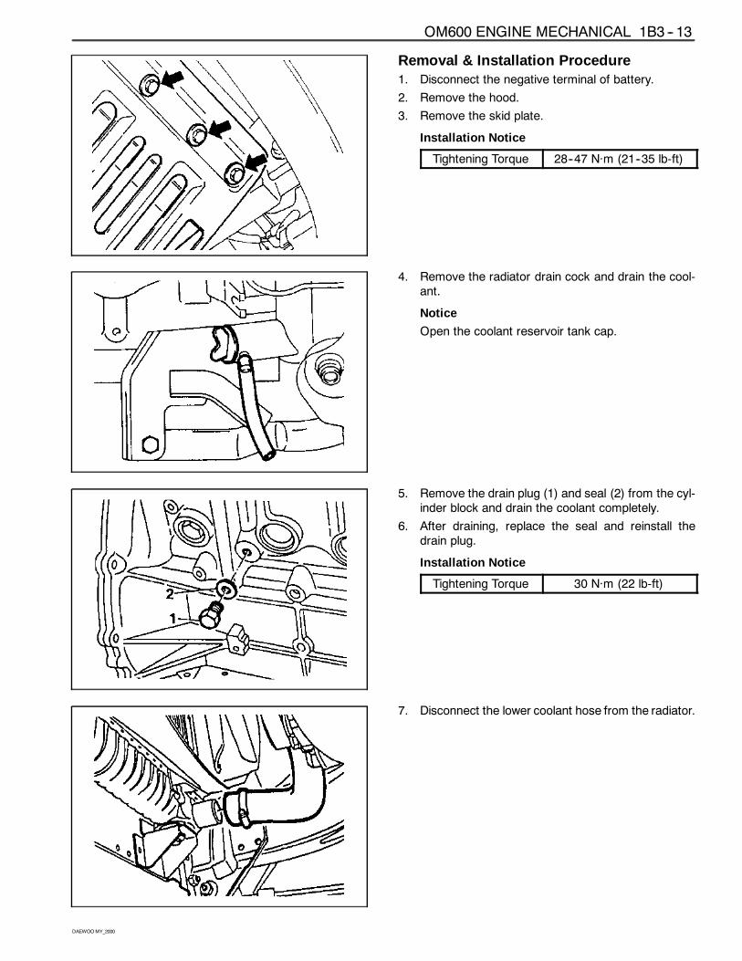
Removal & Installation Procedure1. Disconnect the negative terminal of battery.
2. Remove the hood.
3. Remove the skid plate.
Installation Notice
Tightening Torque 28--47 Năm (21--35 lb-ft)
4. Remove the radiator drain cock and drain the cool-ant.
Notice
Open the coolant reservoir tank cap.
5. Remove the drain plug (1) and seal (2) from the cyl-inder block and drain the coolant completely.
6. After draining, replace the seal and reinstall thedrain plug.
Installation Notice
Tightening Torque 30 Năm (22 lb-ft)
7. Disconnect the lower coolant hose from the radiator.
1B3 -- 14 OM600 ENGINE MECHANICAL
DAEWOOMY_2000
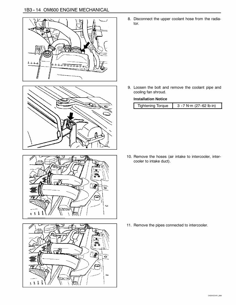
8. Disconnect the upper coolant hose from the radia-tor.
9. Loosen the bolt and remove the coolant pipe andcooling fan shroud.
Installation Notice
Tightening Torque 3 --7 Năm (27--62 lb-in)
10. Remove the hoses (air intake to intercooler, inter-cooler to intake duct).
11. Remove the pipes connected to intercooler.

OM600 ENGINE MECHANICAL 1B3 -- 15
DAEWOOMY_2000
12. Remove the hose(air cleaner to turbocharger) withblow by hose.
13. Disconnect the air cleaner intake hose and removethe air cleaner cover and element.
14. Disconnect the coolant hose from the water inlet.
15. Remove the air--conditioner lines from the compres-sor.
Notice
Evacuate the refrigerant before removal.
1B3 -- 16 OM600 ENGINE MECHANICAL
DAEWOOMY_2000
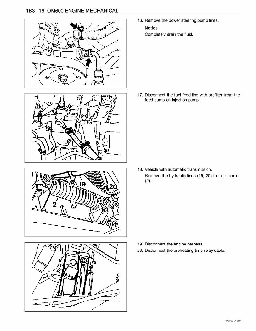
16. Remove the power steering pump lines.
Notice
Completely drain the fluid.
17. Disconnect the fuel feed line with prefilter from thefeed pump on injection pump.
18. Vehicle with automatic transmission.
Remove the hydraulic lines (19, 20) from oil cooler(2).
19. Disconnect the engine harness.
20. Disconnect the preheating time relay cable.
OM600 ENGINE MECHANICAL 1B3 -- 17
DAEWOOMY_2000
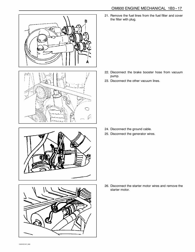
21. Remove the fuel lines from the fuel filter and coverthe filter with plug.
22. Disconnect the brake booster hose from vacuumpump.
23. Disconnect the other vacuum lines.
24. Disconnect the ground cable.
25. Disconnect the generator wires.
26. Disconnect the starter motor wires and remove thestarter motor.
1B3 -- 18 OM600 ENGINE MECHANICAL
DAEWOOMY_2000
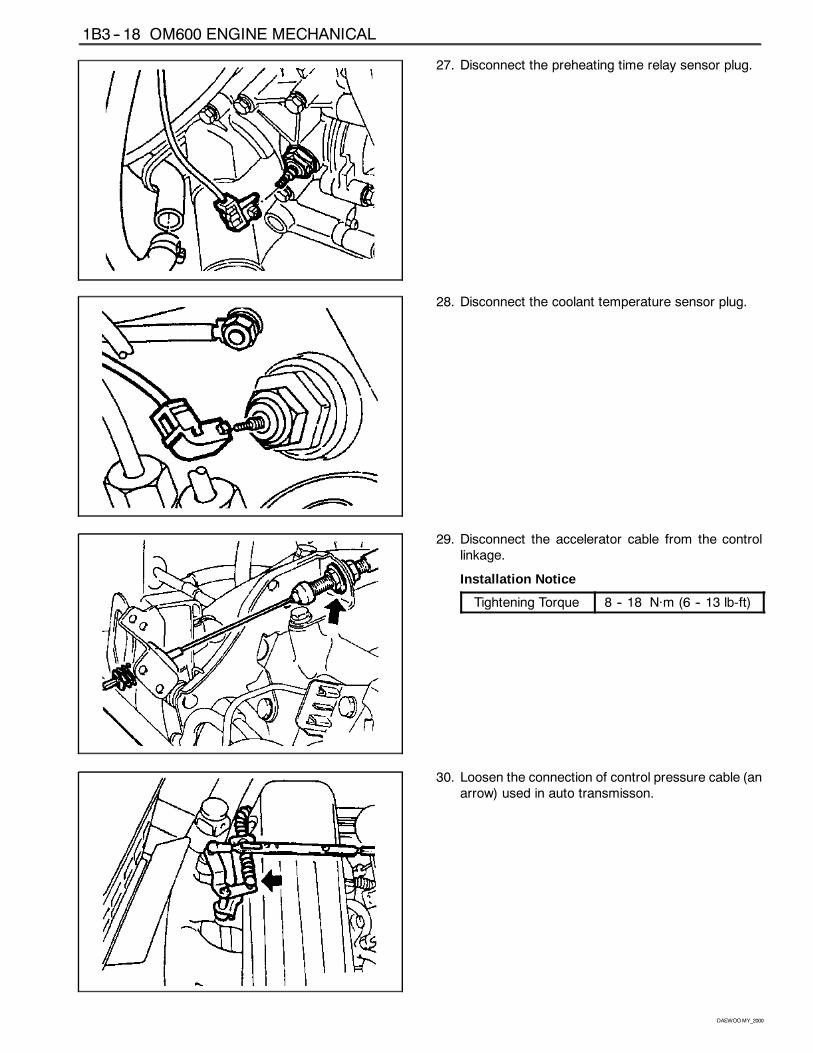
27. Disconnect the preheating time relay sensor plug.
28. Disconnect the coolant temperature sensor plug.
29. Disconnect the accelerator cable from the controllinkage.
Installation Notice
Tightening Torque 8 -- 18 Năm (6 -- 13 lb-ft)
30. Loosen the connection of control pressure cable (anarrow) used in auto transmisson.
OM600 ENGINE MECHANICAL 1B3 -- 19
DAEWOOMY_2000
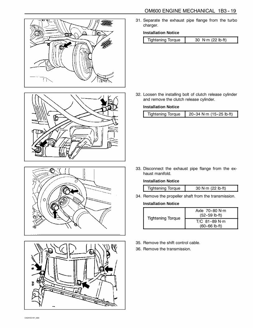
31. Separate the exhaust pipe flange from the turbocharger.
Installation Notice
Tightening Torque 30 Năm (22 lb-ft)
32. Loosen the installing bolt of clutch release cylinderand remove the clutch release cylinder.
Installation Notice
Tightening Torque 20--34 Năm (15--25 lb-ft)
33. Disconnect the exhaust pipe flange from the ex-haust manifold.
Installation Notice
Tightening Torque 30 Năm (22 lb-ft)
34. Remove the propeller shaft from the transmission.
Installation Notice
Tightening Torque
Axle 70--80 Năm(52--59 lb-ft)
Tightening TorqueT/C 81--89 Năm(60--66 lb-ft)
35. Remove the shift control cable.
36. Remove the transmission.
1B3 -- 20 OM600 ENGINE MECHANICAL
DAEWOOMY_2000
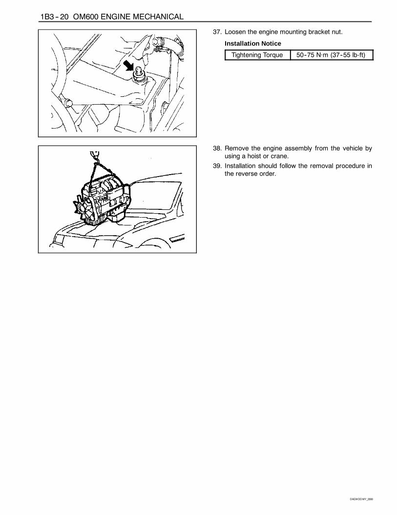
37. Loosen the engine mounting bracket nut.
Installation Notice
Tightening Torque 50--75 Năm (37--55 lb-ft)
38. Remove the engine assembly from the vehicle byusing a hoist or crane.
39. Installation should follow the removal procedure inthe reverse order.
OM600 ENGINE MECHANICAL 1B3 -- 21
DAEWOOMY_2000
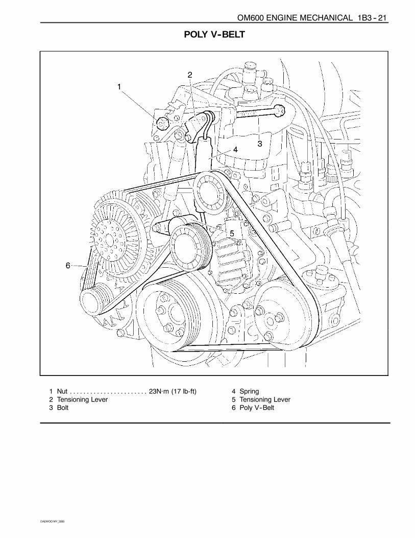
POLY V--BELT
1 Nut 23Năm (17 lb-ft). . . . . . . . . . . . . . . . . . . . . . .2 Tensioning Lever3 Bolt
4 Spring5 Tensioning Lever6 Poly V--Belt
1B3 -- 22 OM600 ENGINE MECHANICAL
DAEWOOMY_2000
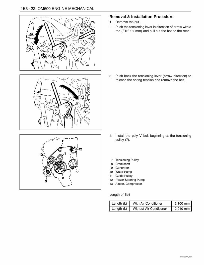
Removal & Installation Procedure1. Remove the nut.
2. Push the tensioning lever in direction of arrow with arod (F12’ 180mm) and pull out the bolt to the rear.
3. Push back the tensioning lever (arrow direction) torelease the spring tension and remove the belt.
4. Install the poly V--belt beginning at the tensioningpulley (7).
7 Tensioning Pulley
8 Crankshaft
9 Generator
10 Water Pump
11 Guide Pulley
12 Power Steering Pump
13 Aircon. Compressor
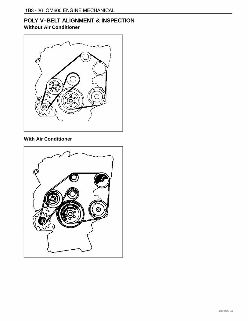
Length of Belt
Length (L) With Air Conditioner 2,100 mm
Length (L) Without Air Conditioner 2,040 mm
OM600 ENGINE MECHANICAL 1B3 -- 23
DAEWOOMY_2000
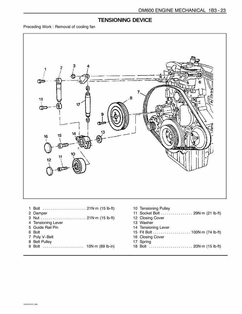
TENSIONING DEVICEPreceding Work : Removal of cooling fan
1 Bolt 21Năm (15 lb-ft). . . . . . . . . . . . . . . . . . . . . .2 Damper3 Nut 21Năm (15 lb-ft). . . . . . . . . . . . . . . . . . . . . . .4 Tensioning Lever5 Guide Rail Pin6 Bolt7 Poly V--Belt8 Belt Pulley9 Bolt 10Năm (89 lb-in). . . . . . . . . . . . . . . . . . . . .
10 Tensioning Pulley11 Socket Bolt 29Năm (21 lb-ft). . . . . . . . . . . . . . . .12 Closing Cover13 Washer14 Tensioning Lever15 Fit Bolt 100Năm (74 lb-ft). . . . . . . . . . . . . . . . . . .16 Closing Cover17 Spring18 Bolt 20Năm (15 lb-ft). . . . . . . . . . . . . . . . . . . . . .
1B3 -- 24 OM600 ENGINE MECHANICAL
DAEWOOMY_2000
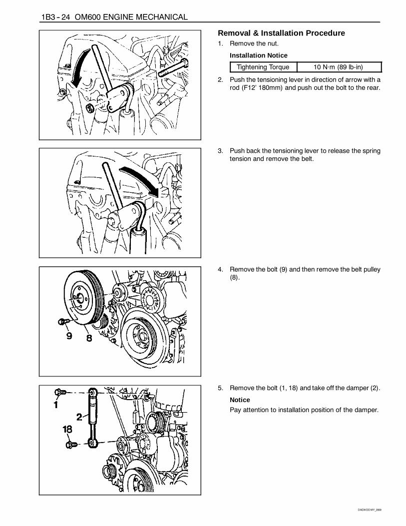
Removal & Installation Procedure1. Remove the nut.
Installation Notice
Tightening Torque 10 Năm (89 lb-in)
2. Push the tensioning lever in direction of arrow with arod (F12’ 180mm) and push out the bolt to the rear.
3. Push back the tensioning lever to release the springtension and remove the belt.
4. Remove the bolt (9) and then remove the belt pulley(8).
5. Remove the bolt (1, 18) and take off the damper (2).
Notice
Pay attention to installation position of the damper.
OM600 ENGINE MECHANICAL 1B3 -- 25
DAEWOOMY_2000
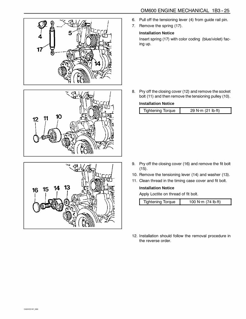
6. Pull off the tensioning lever (4) from guide rail pin.
7. Remove the spring (17).
Installation Notice
Insert spring (17) with color coding (blue/violet) fac-ing up.
8. Pry off the closing cover (12) and remove the socketbolt (11) and then remove the tensioning pulley (10).
Installation Notice
Tightening Torque 29 Năm (21 lb-ft)
9. Pry off the closing cover (16) and remove the fit bolt(15).
10. Remove the tensioning lever (14) and washer (13).
11. Clean thread in the timing case cover and fit bolt.
Installation Notice
Apply Loctite on thread of fit bolt.
Tightening Torque 100 Năm (74 lb-ft)
12. Installation should follow the removal procedure inthe reverse order.
1B3 -- 26 OM600 ENGINE MECHANICAL
DAEWOOMY_2000
POLY V--BELT ALIGNMENT & INSPECTIONWithout Air Conditioner
With Air Conditioner
OM600 ENGINE MECHANICAL 1B3 -- 27
DAEWOOMY_2000
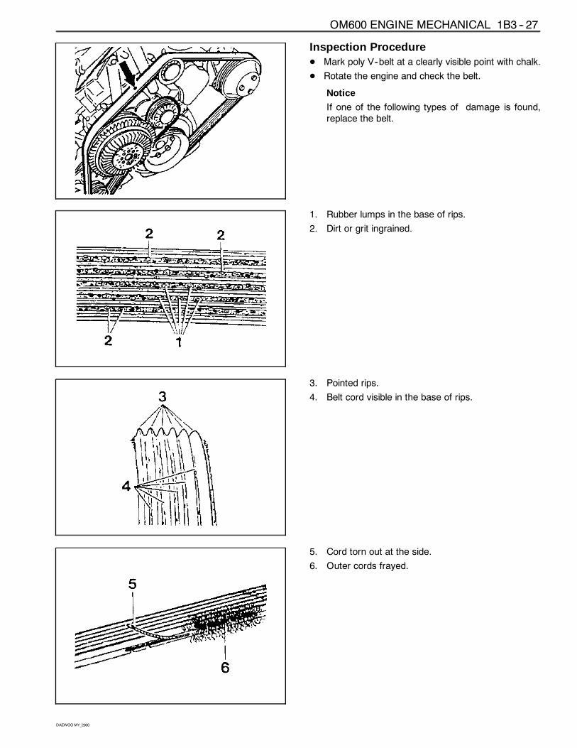
Inspection ProcedureD Mark poly V--belt at a clearly visible point with chalk.
D Rotate the engine and check the belt.
Notice
If one of the following types of damage is found,replace the belt.
1. Rubber lumps in the base of rips.
2. Dirt or grit ingrained.
3. Pointed rips.
4. Belt cord visible in the base of rips.
5. Cord torn out at the side.
6. Outer cords frayed.
1B3 -- 28 OM600 ENGINE MECHANICAL
DAEWOOMY_2000
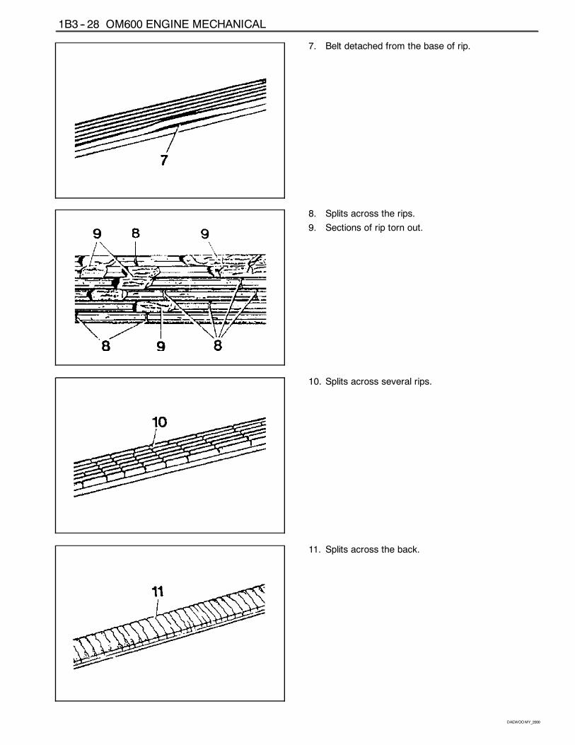
7. Belt detached from the base of rip.
8. Splits across the rips.
9. Sections of rip torn out.
10. Splits across several rips.
11. Splits across the back.
OM600 ENGINE MECHANICAL 1B3 -- 29
DAEWOOMY_2000
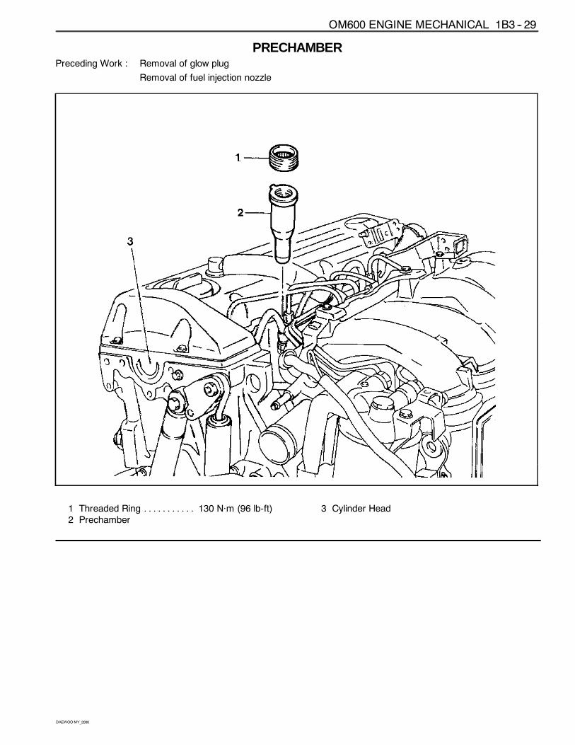
PRECHAMBERPreceding Work : Removal of glow plug
Removal of fuel injection nozzle
1 Threaded Ring 130 Năm (96 lb-ft). . . . . . . . . . .2 Prechamber
3 Cylinder Head
1B3 -- 30 OM600 ENGINE MECHANICAL
DAEWOOMY_2000
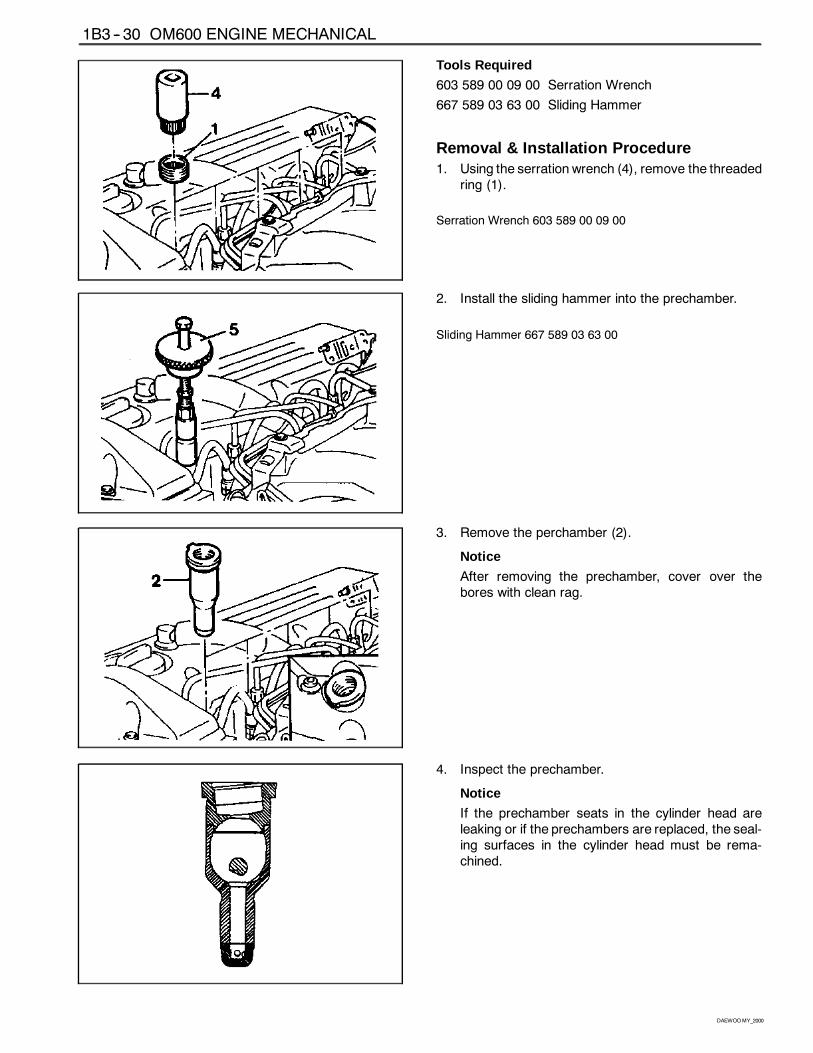
Tools Required
603 589 00 09 00 Serration Wrench
667 589 03 63 00 Sliding Hammer
Removal & Installation Procedure1. Using the serration wrench (4), remove the threaded
ring (1).
Serration Wrench 603 589 00 09 00
2. Install the sliding hammer into the prechamber.
Sliding Hammer 667 589 03 63 00
3. Remove the perchamber (2).
Notice
After removing the prechamber, cover over thebores with clean rag.
4. Inspect the prechamber.
Notice
If the prechamber seats in the cylinder head areleaking or if the prechambers are replaced, the seal-ing surfaces in the cylinder head must be rema-chined.
OM600 ENGINE MECHANICAL 1B3 -- 31
DAEWOOMY_2000
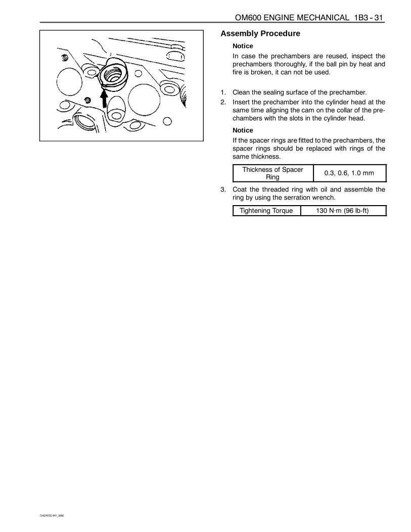
Assembly Procedure
Notice
In case the prechambers are reused, inspect theprechambers thoroughly, if the ball pin by heat andfire is broken, it can not be used.
1. Clean the sealing surface of the prechamber.
2. Insert the prechamber into the cylinder head at thesame time aligning the cam on the collar of the pre-chambers with the slots in the cylinder head.
Notice
If the spacer rings are fitted to the prechambers, thespacer rings should be replaced with rings of thesame thickness.
Thickness of SpacerRing
0.3, 0.6, 1.0 mm
3. Coat the threaded ring with oil and assemble thering by using the serration wrench.
Tightening Torque 130 Năm (96 lb-ft)
1B3 -- 32 OM600 ENGINE MECHANICAL
DAEWOOMY_2000
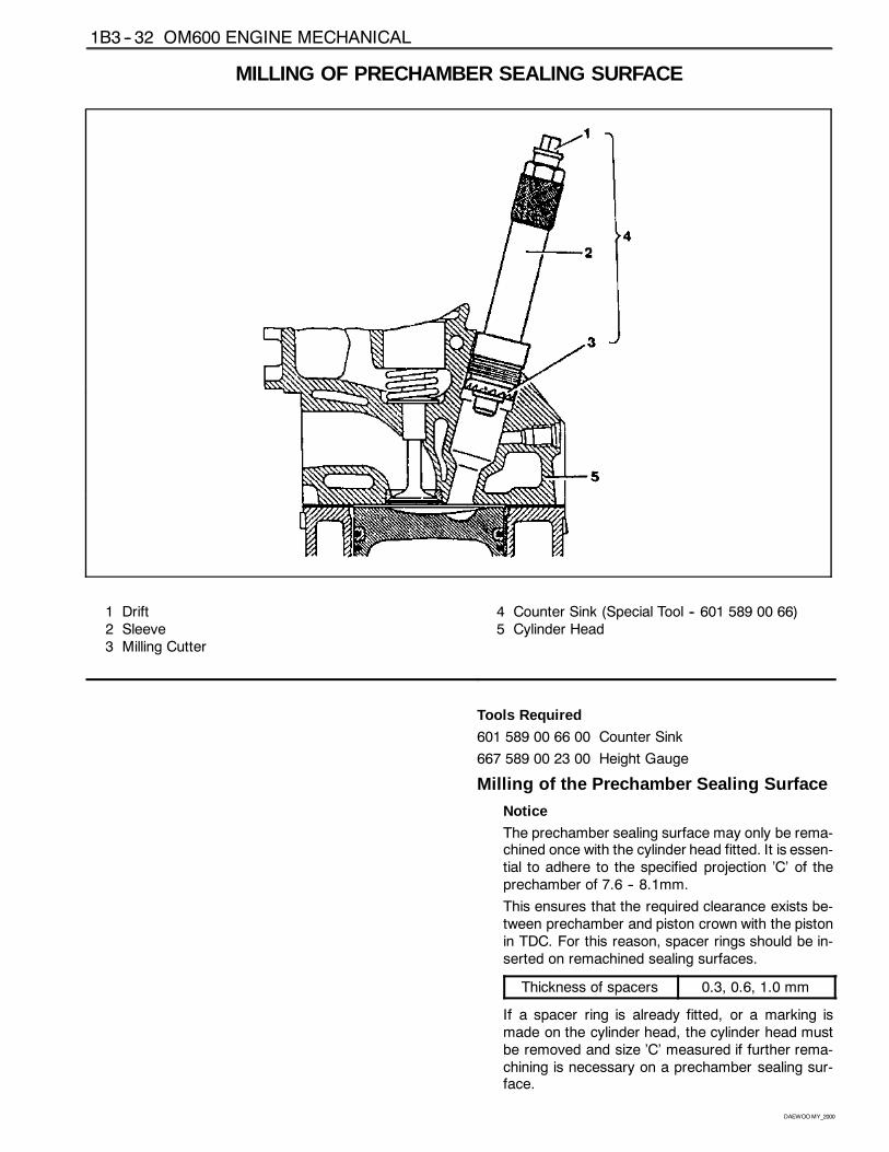
MILLING OF PRECHAMBER SEALING SURFACE
1 Drift2 Sleeve3 Milling Cutter
4 Counter Sink (Special Tool -- 601 589 00 66)5 Cylinder Head
Tools Required
601 589 00 66 00 Counter Sink
667 589 00 23 00 Height Gauge
Milling of the Prechamber Sealing Surface
Notice
The prechamber sealing surface may only be rema-chined once with the cylinder head fitted. It is essen-tial to adhere to the specified projection ’C’ of theprechamber of 7.6 -- 8.1mm.
This ensures that the required clearance exists be-tween prechamber and piston crown with the pistonin TDC. For this reason, spacer rings should be in-serted on remachined sealing surfaces.
Thickness of spacers 0.3, 0.6, 1.0 mm
If a spacer ring is already fitted, or a marking ismade on the cylinder head, the cylinder head mustbe removed and size ’C’ measured if further rema-chining is necessary on a prechamber sealing sur-face.
OM600 ENGINE MECHANICAL 1B3 -- 33
DAEWOOMY_2000
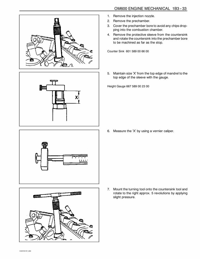
1. Remove the injection nozzle.
2. Remove the prechamber.
3. Cover the prechamber bore to avoid any chips drop-ping into the combustion chamber.
4. Remove the protective sleeve from the countersinkand rotate the countersink into the prechamber boreto be machined as far as the stop.
Counter Sink 601 589 00 66 00
5. Maintain size ’X’ from the top edge of mandrel to thetop edge of the sleeve with the gauge.
Height Gauge 667 589 00 23 00
6. Measure the ’X’ by using a vernier caliper.
7. Mount the turning tool onto the countersink tool androtate to the right approx. 5 revolutions by applyingslight pressure.
1B3 -- 34 OM600 ENGINE MECHANICAL
DAEWOOMY_2000
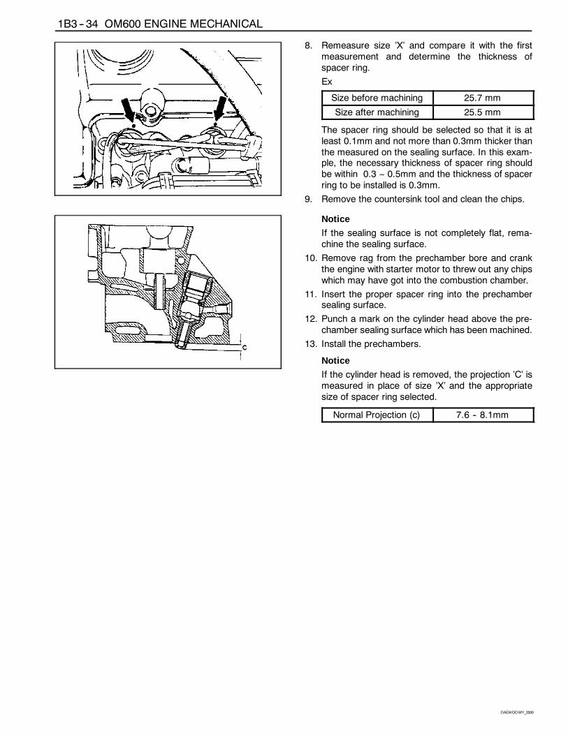
8. Remeasure size ’X’ and compare it with the firstmeasurement and determine the thickness ofspacer ring.
Ex
Size before machining 25.7 mm
Size after machining 25.5 mm
The spacer ring should be selected so that it is atleast 0.1mm and not more than 0.3mm thicker thanthe measured on the sealing surface. In this exam-ple, the necessary thickness of spacer ring shouldbe within 0.3 ~ 0.5mm and the thickness of spacerring to be installed is 0.3mm.
9. Remove the countersink tool and clean the chips.
Notice
If the sealing surface is not completely flat, rema-chine the sealing surface.
10. Remove rag from the prechamber bore and crankthe engine with starter motor to threw out any chipswhich may have got into the combustion chamber.
11. Insert the proper spacer ring into the prechambersealing surface.
12. Punch a mark on the cylinder head above the pre-chamber sealing surface which has been machined.
13. Install the prechambers.
Notice
If the cylinder head is removed, the projection ’C’ ismeasured in place of size ’X’ and the appropriatesize of spacer ring selected.
Normal Projection (c) 7.6 -- 8.1mm
OM600 ENGINE MECHANICAL 1B3 -- 35
DAEWOOMY_2000
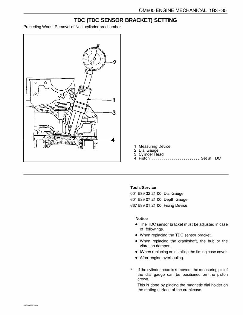
TDC (TDC SENSOR BRACKET) SETTINGPreceding Work : Removal of No.1 cylinder prechamber
1 Measuring Device2 Dial Gauge3 Cylinder Head4 Piston Set at TDC. . . . . . . . . . . . . . . . . . . . . . . .
Tools Service
001 589 32 21 00 Dial Gauge
601 589 07 21 00 Depth Gauge
667 589 01 21 00 Fixing Device
NoticeD The TDC sensor bracket must be adjusted in caseof followings.
D When replacing the TDC sensor bracket.
D When replacing the crankshaft, the hub or thevibration damper.
D lWhen replacing or installing the timing case cover.
D After engine overhauling.
* If the cylinder head is removed, themeasuring pin ofthe dial gauge can be positioned on the pistoncrown.
This is done by placing the magnetic dial holder onthe mating surface of the crankcase.
1B3 -- 36 OM600 ENGINE MECHANICAL
DAEWOOMY_2000
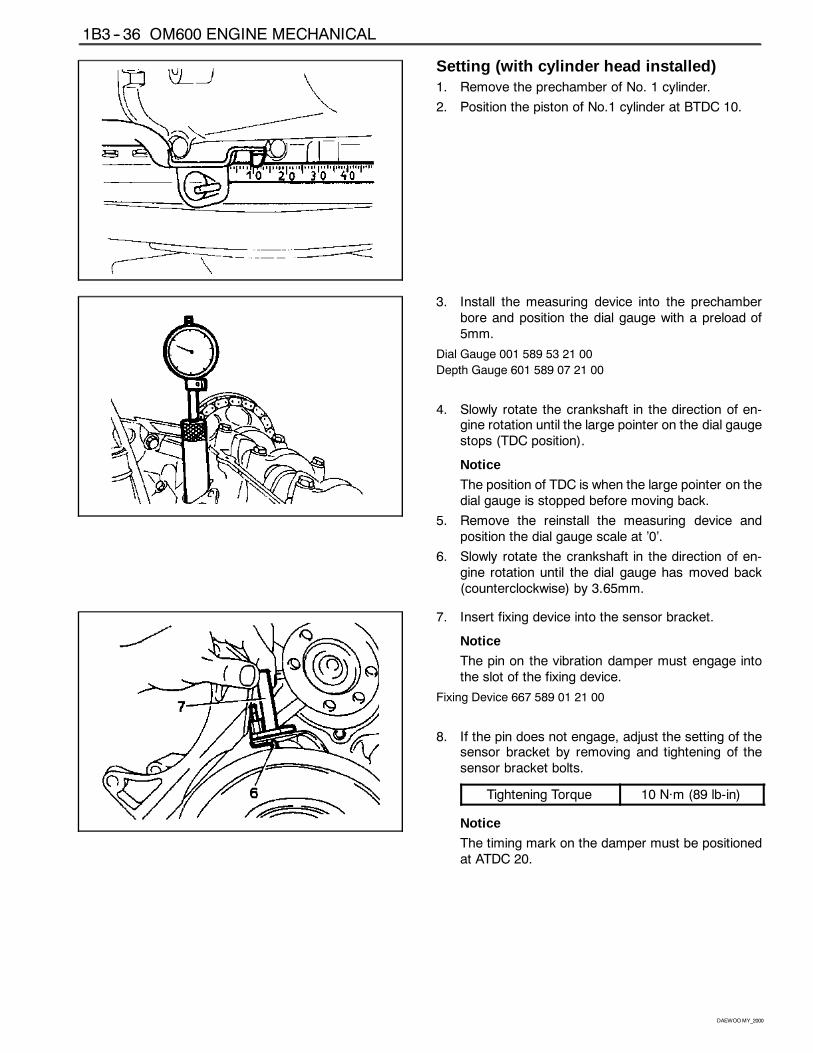
Setting (with cylinder head installed)1. Remove the prechamber of No. 1 cylinder.
2. Position the piston of No.1 cylinder at BTDC 10.
3. Install the measuring device into the prechamberbore and position the dial gauge with a preload of5mm.
Dial Gauge 001 589 53 21 00
Depth Gauge 601 589 07 21 00
4. Slowly rotate the crankshaft in the direction of en-gine rotation until the large pointer on the dial gaugestops (TDC position).
Notice
The position of TDC is when the large pointer on thedial gauge is stopped before moving back.
5. Remove the reinstall the measuring device andposition the dial gauge scale at ’0’.
6. Slowly rotate the crankshaft in the direction of en-gine rotation until the dial gauge has moved back(counterclockwise) by 3.65mm.
7. Insert fixing device into the sensor bracket.
Notice
The pin on the vibration damper must engage intothe slot of the fixing device.
Fixing Device 667 589 01 21 00
8. If the pin does not engage, adjust the setting of thesensor bracket by removing and tightening of thesensor bracket bolts.
Tightening Torque 10 Năm (89 lb-in)
Notice
The timing mark on the damper must be positionedat ATDC 20.
OM600 ENGINE MECHANICAL 1B3 -- 37
DAEWOOMY_2000
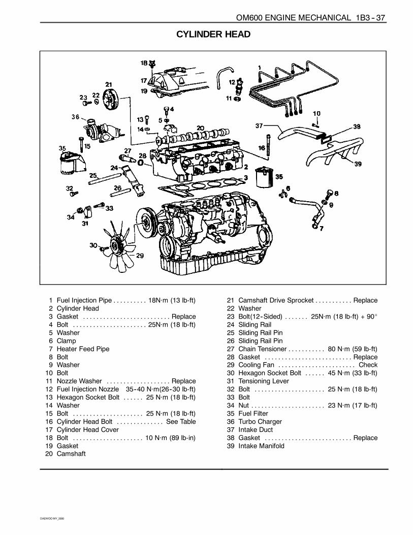
CYLINDER HEAD
1 Fuel Injection Pipe 18Năm (13 lb-ft). . . . . . . . . .2 Cylinder Head3 Gasket Replace. . . . . . . . . . . . . . . . . . . . . . . . . .4 Bolt 25Năm (18 lb-ft). . . . . . . . . . . . . . . . . . . . . .5 Washer6 Clamp7 Heater Feed Pipe8 Bolt9 Washer10 Bolt11 Nozzle Washer Replace. . . . . . . . . . . . . . . . . . .12 Fuel Injection Nozzle 35--40 Năm(26--30 lb-ft)13 Hexagon Socket Bolt 25 Năm (18 lb-ft). . . . . .14 Washer15 Bolt 25 Năm (18 lb-ft). . . . . . . . . . . . . . . . . . . . .16 Cylinder Head Bolt See Table. . . . . . . . . . . . . .17 Cylinder Head Cover18 Bolt 10 Năm (89 lb-in). . . . . . . . . . . . . . . . . . . . .19 Gasket20 Camshaft
21 Camshaft Drive Sprocket Replace. . . . . . . . . . .22 Washer23 Bolt(12--Sided) 25Năm (18 lb-ft) + 90_. . . . . . .24 Sliding Rail25 Sliding Rail Pin26 Sliding Rail Pin27 Chain Tensioner 80 Năm (59 lb-ft). . . . . . . . . . .28 Gasket Replace. . . . . . . . . . . . . . . . . . . . . . . . . .29 Cooling Fan Check. . . . . . . . . . . . . . . . . . . . . . .30 Hexagon Socket Bolt 45 Năm (33 lb-ft). . . . . .31 Tensioning Lever32 Bolt 25 Năm (18 lb-ft). . . . . . . . . . . . . . . . . . . . .33 Bolt34 Nut 23 Năm (17 lb-ft). . . . . . . . . . . . . . . . . . . . . .35 Fuel Filter36 Turbo Charger37 Intake Duct38 Gasket Replace. . . . . . . . . . . . . . . . . . . . . . . . . .39 Intake Manifold
1B3 -- 38 OM600 ENGINE MECHANICAL
DAEWOOMY_2000
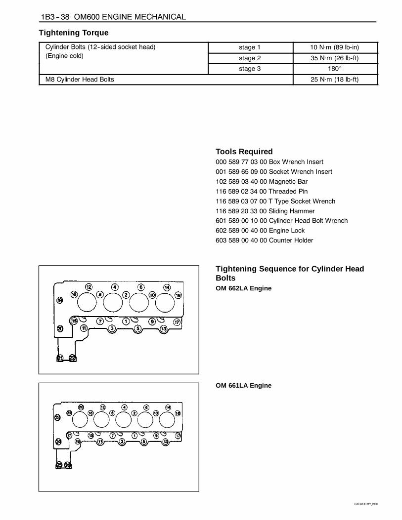
Tightening Torque
Cylinder Bolts (12--sided socket head) stage 1 10 Năm (89 lb-in)y ( )
(Engine cold) stage 2 35 Năm (26 lb-ft)
stage 3 180_
M8 Cylinder Head Bolts 25 Năm (18 lb-ft)
Tools Required000 589 77 03 00 Box Wrench Insert
001 589 65 09 00 Socket Wrench Insert
102 589 03 40 00 Magnetic Bar
116 589 02 34 00 Threaded Pin
116 589 03 07 00 T Type Socket Wrench
116 589 20 33 00 Sliding Hammer
601 589 00 10 00 Cylinder Head Bolt Wrench
602 589 00 40 00 Engine Lock
603 589 00 40 00 Counter Holder
Tightening Sequence for Cylinder HeadBoltsOM 662LA Engine
OM 661LA Engine
OM600 ENGINE MECHANICAL 1B3 -- 39
DAEWOOMY_2000
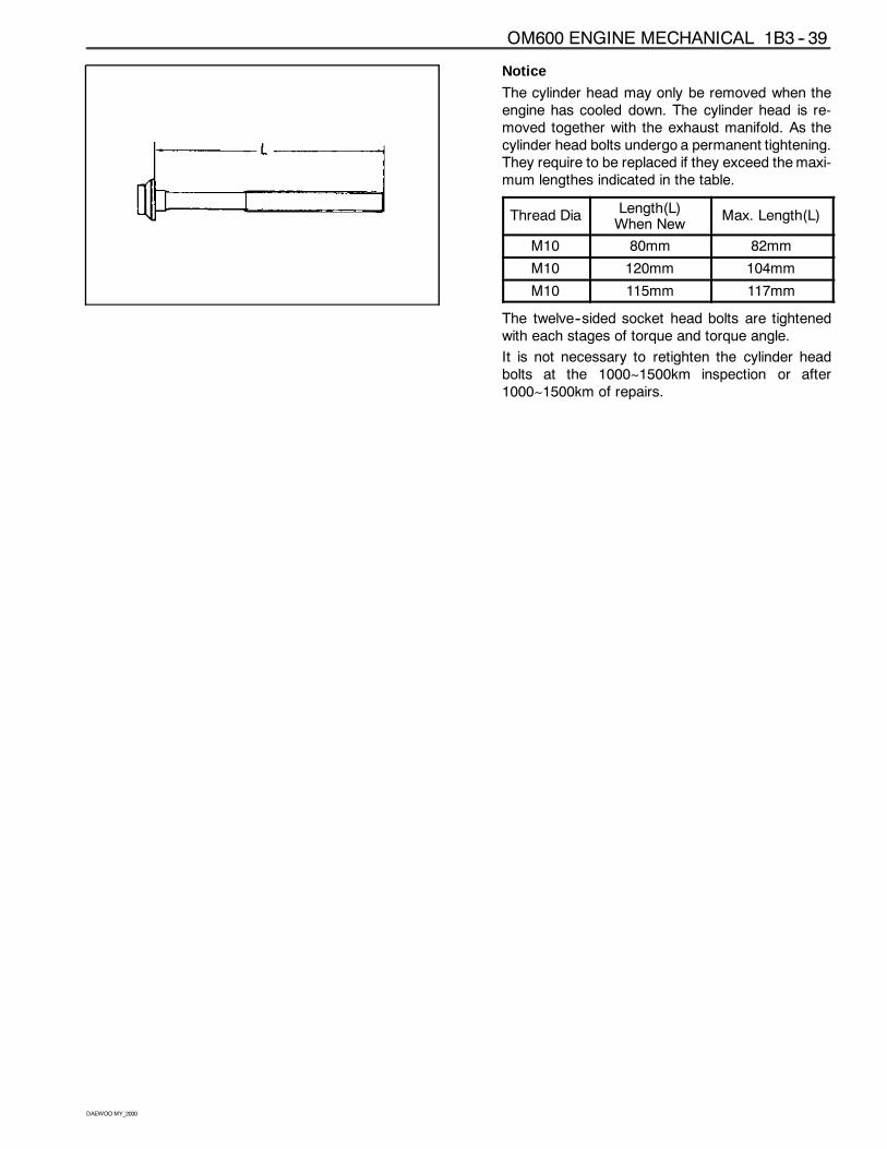
Notice
The cylinder head may only be removed when theengine has cooled down. The cylinder head is re-moved together with the exhaust manifold. As thecylinder head bolts undergo a permanent tightening.They require to be replaced if they exceed themaxi-mum lengthes indicated in the table.
Thread DiaLength(L)When New
Max. Length(L)
M10 80mm 82mm
M10 120mm 104mm
M10 115mm 117mm
The twelve--sided socket head bolts are tightenedwith each stages of torque and torque angle.
It is not necessary to retighten the cylinder headbolts at the 1000~1500km inspection or after1000~1500km of repairs.
1B3 -- 40 OM600 ENGINE MECHANICAL
DAEWOOMY_2000
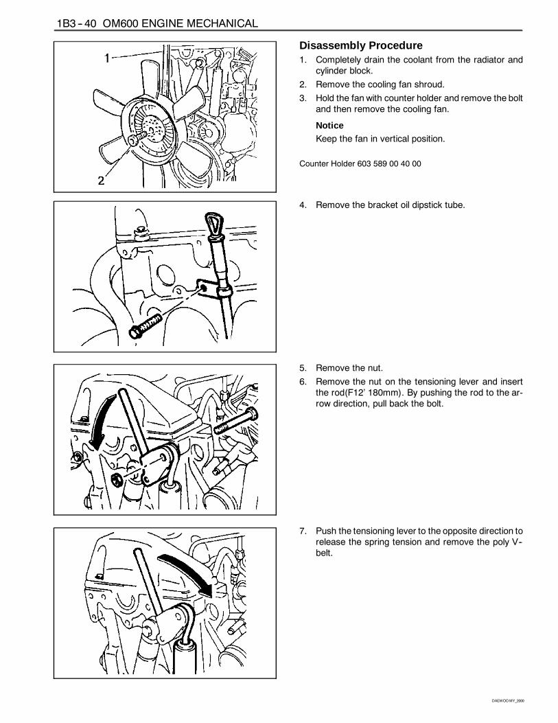
Disassembly Procedure1. Completely drain the coolant from the radiator and
cylinder block.
2. Remove the cooling fan shroud.
3. Hold the fan with counter holder and remove the boltand then remove the cooling fan.
NoticeKeep the fan in vertical position.
Counter Holder 603 589 00 40 00
4. Remove the bracket oil dipstick tube.
5. Remove the nut.
6. Remove the nut on the tensioning lever and insertthe rod(F12’ 180mm). By pushing the rod to the ar-row direction, pull back the bolt.
7. Push the tensioning lever to the opposite direction torelease the spring tension and remove the poly V--belt.
OM600 ENGINE MECHANICAL 1B3 -- 41
DAEWOOMY_2000
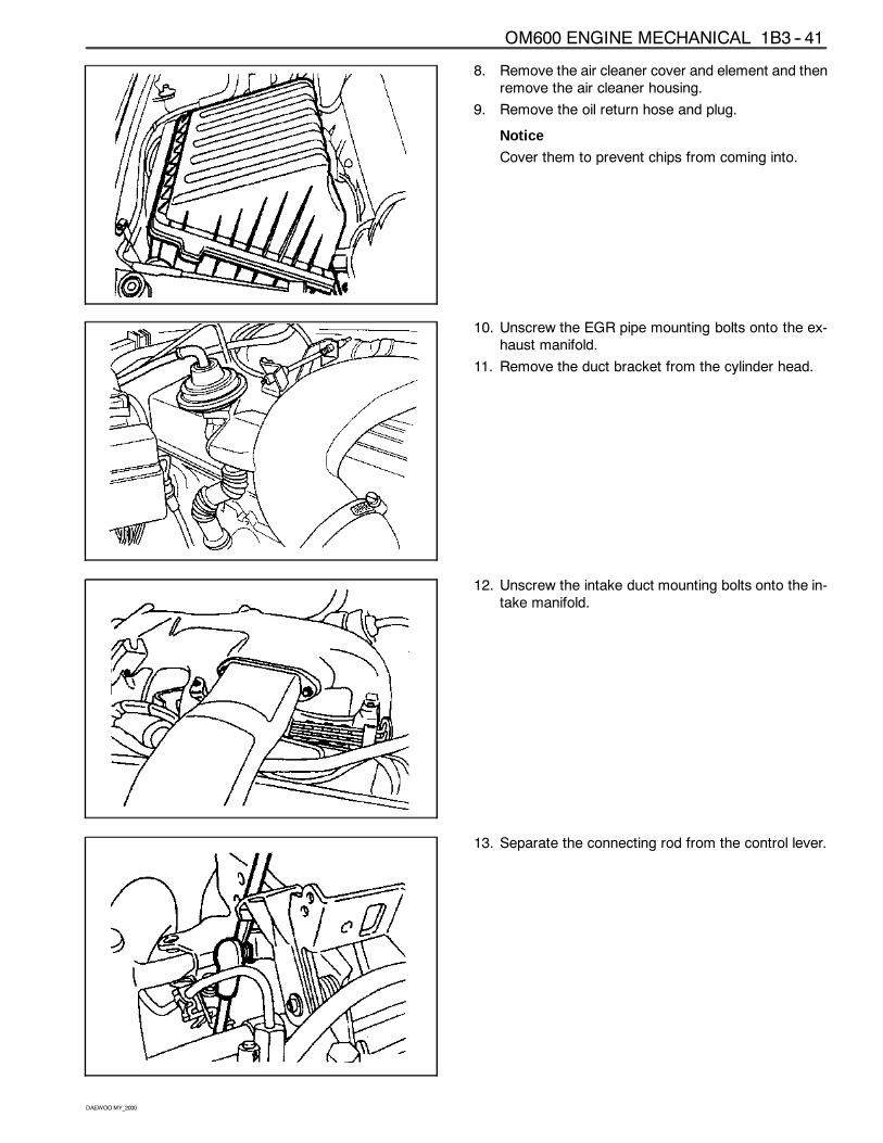
8. Remove the air cleaner cover and element and thenremove the air cleaner housing.
9. Remove the oil return hose and plug.
Notice
Cover them to prevent chips from coming into.
10. Unscrew the EGR pipe mounting bolts onto the ex-haust manifold.
11. Remove the duct bracket from the cylinder head.
12. Unscrew the intake duct mounting bolts onto the in-take manifold.
13. Separate the connecting rod from the control lever.
1B3 -- 42 OM600 ENGINE MECHANICAL
DAEWOOMY_2000
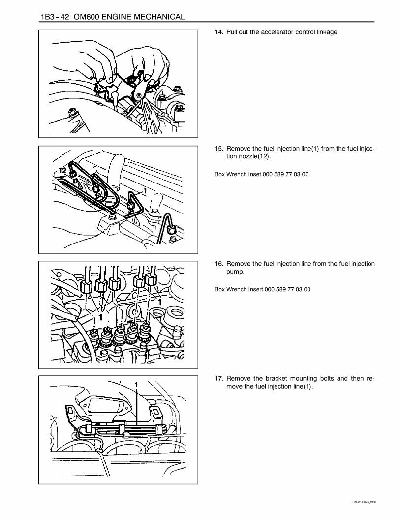
14. Pull out the accelerator control linkage.
15. Remove the fuel injection line(1) from the fuel injec-tion nozzle(12).
Box Wrench Inset 000 589 77 03 00
16. Remove the fuel injection line from the fuel injectionpump.
Box Wrench Insert 000 589 77 03 00
17. Remove the bracket mounting bolts and then re-move the fuel injection line(1).
OM600 ENGINE MECHANICAL 1B3 -- 43
DAEWOOMY_2000
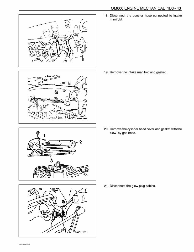
18. Disconnect the booster hose connected to intakemanifold.
19. Remove the intake manifold and gasket.
20. Remove the cylinder head cover and gasket with theblow--by gas hose.
21. Disconnect the glow plug cables.
1B3 -- 44 OM600 ENGINE MECHANICAL
DAEWOOMY_2000
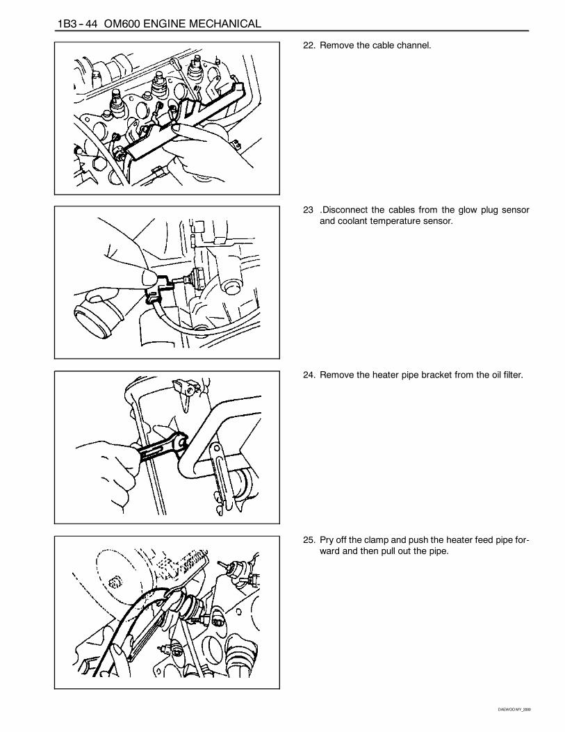
22. Remove the cable channel.
23 .Disconnect the cables from the glow plug sensorand coolant temperature sensor.
24. Remove the heater pipe bracket from the oil filter.
25. Pry off the clamp and push the heater feed pipe for-ward and then pull out the pipe.
OM600 ENGINE MECHANICAL 1B3 -- 45
DAEWOOMY_2000
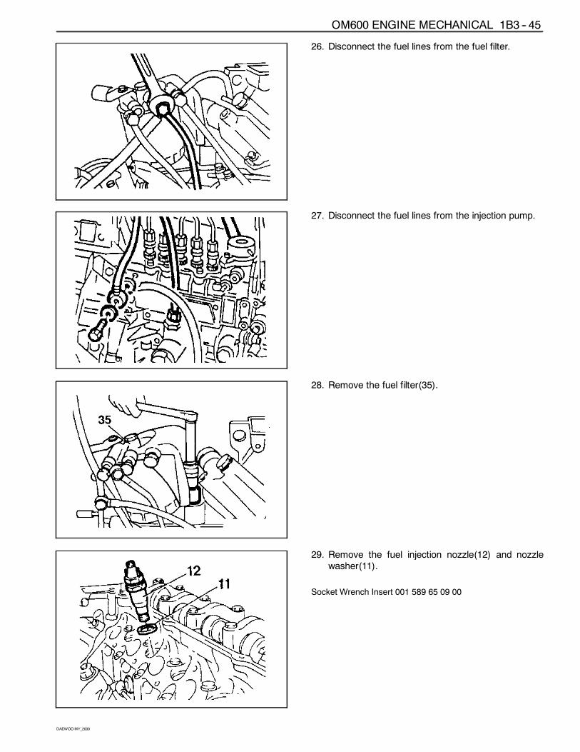
26. Disconnect the fuel lines from the fuel filter.
27. Disconnect the fuel lines from the injection pump.
28. Remove the fuel filter(35).
29. Remove the fuel injection nozzle(12) and nozzlewasher(11).
Socket Wrench Insert 001 589 65 09 00
OM600 ENGINE MECHANICAL 1B3 -- 47
DAEWOOMY_2000
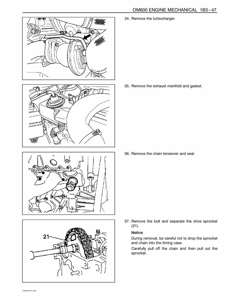
34. Remove the turbocharger.
35. Remove the exhaust manifold and gasket.
36. Remove the chain tensioner and seal.
37. Remove the bolt and separate the drive sprocket(21).
Notice
During removal, be careful not to drop the sprocketand chain into the timing case.
Carefully pull off the chain and then pull out thesprocket.
1B3 -- 46 OM600 ENGINE MECHANICAL
DAEWOOMY_2000
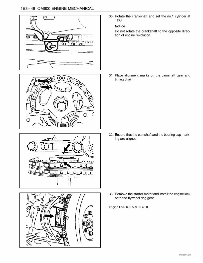
30. Rotate the crankshaft and set the no.1 cylinder atTDC.
Notice
Do not rotate the crankshaft to the opposite direc-tion of engine revolution.
31. Place alignment marks on the camshaft gear andtiming chain.
32. Ensure that the camshaft and the bearing capmark-ing are aligned.
33. Remove the starter motor and install the engine lockonto the flywheel ring gear.
Engine Lock 602 589 00 40 00
1B3 -- 48 OM600 ENGINE MECHANICAL
DAEWOOMY_2000
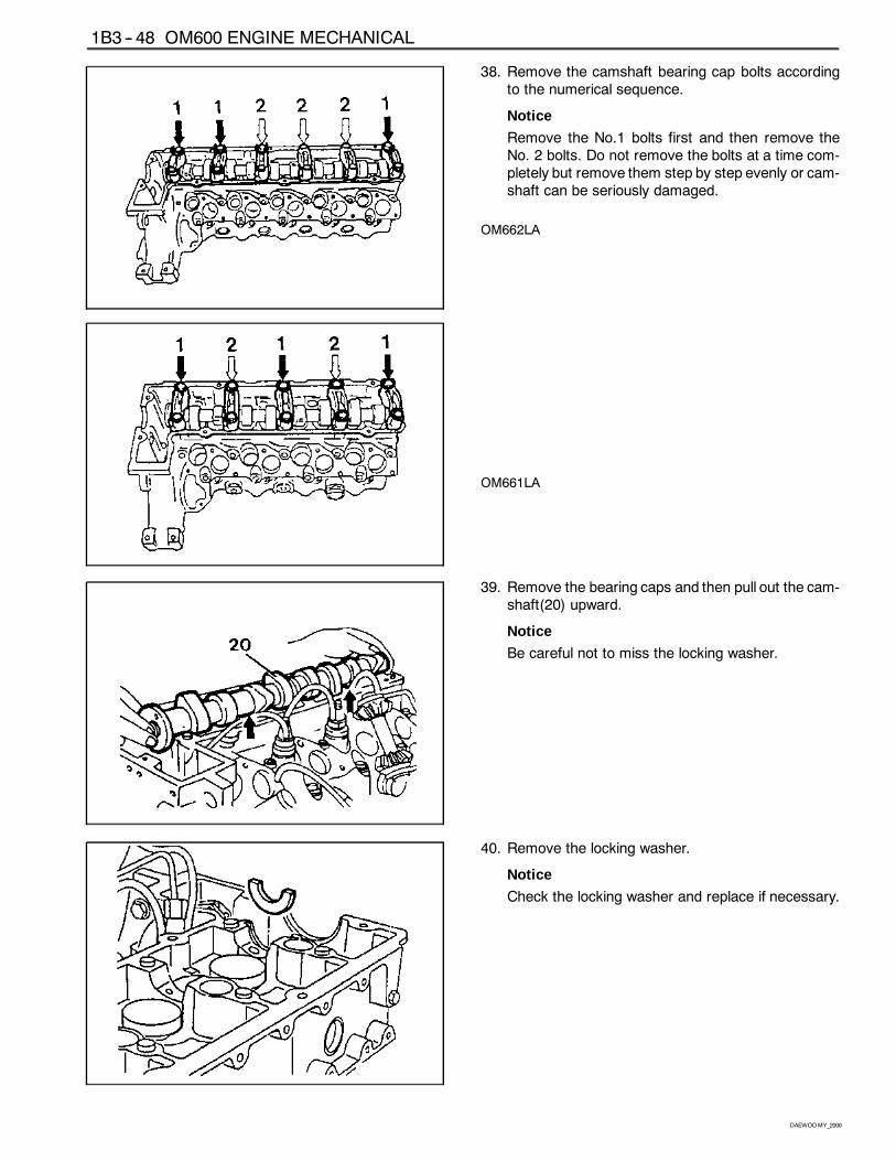
38. Remove the camshaft bearing cap bolts accordingto the numerical sequence.
Notice
Remove the No.1 bolts first and then remove theNo. 2 bolts. Do not remove the bolts at a time com-pletely but remove them step by step evenly or cam-shaft can be seriously damaged.
OM662LA
OM661LA
39. Remove the bearing caps and then pull out the cam-shaft(20) upward.
Notice
Be careful not to miss the locking washer.
40. Remove the locking washer.
Notice
Check the locking washer and replace if necessary.
OM600 ENGINE MECHANICAL 1B3 -- 49
DAEWOOMY_2000
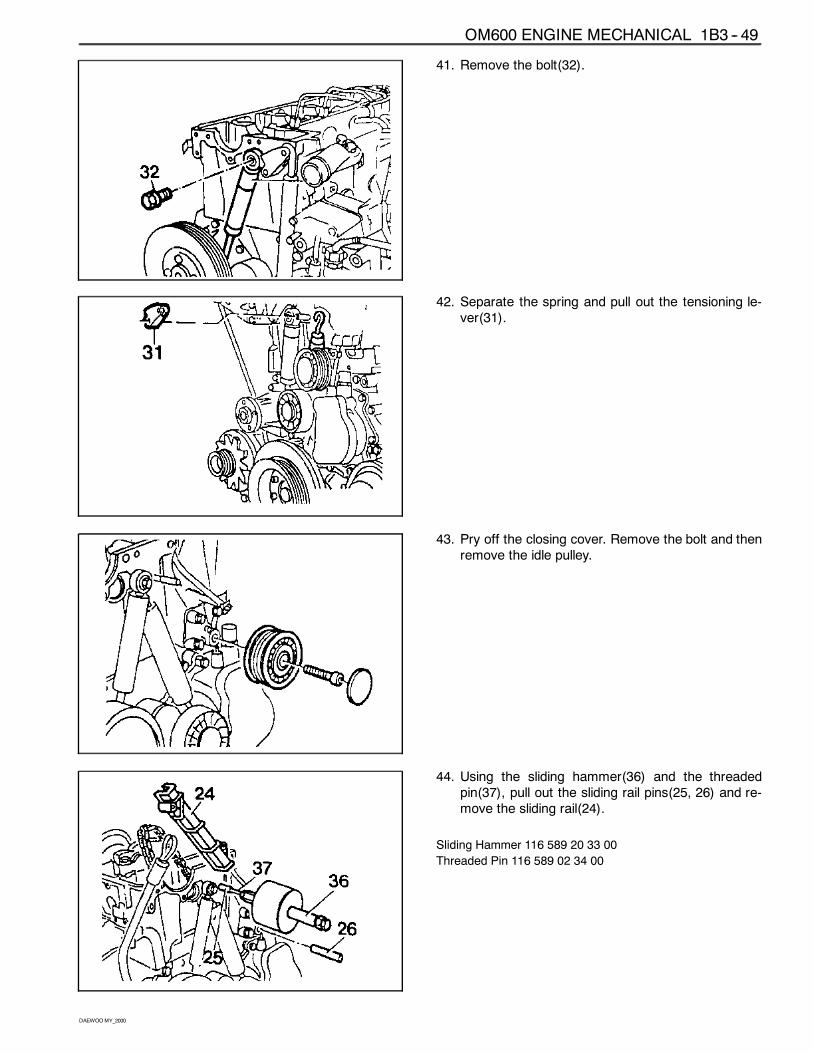
41. Remove the bolt(32).
42. Separate the spring and pull out the tensioning le-ver(31).
43. Pry off the closing cover. Remove the bolt and thenremove the idle pulley.
44. Using the sliding hammer(36) and the threadedpin(37), pull out the sliding rail pins(25, 26) and re-move the sliding rail(24).
Sliding Hammer 116 589 20 33 00
Threaded Pin 116 589 02 34 00
1B3 -- 50 OM600 ENGINE MECHANICAL
DAEWOOMY_2000
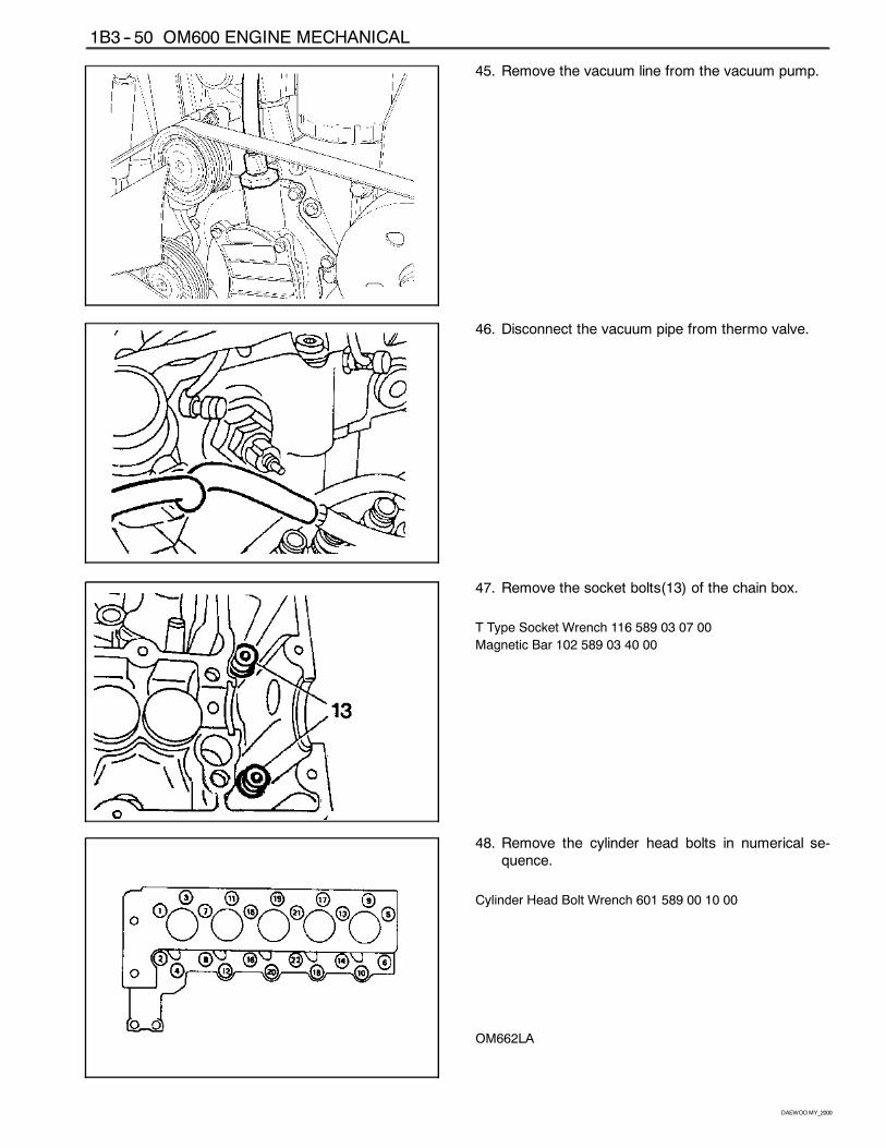
45. Remove the vacuum line from the vacuum pump.
46. Disconnect the vacuum pipe from thermo valve.
47. Remove the socket bolts(13) of the chain box.
T Type Socket Wrench 116 589 03 07 00
Magnetic Bar 102 589 03 40 00
48. Remove the cylinder head bolts in numerical se-quence.
Cylinder Head Bolt Wrench 601 589 00 10 00
OM662LA
OM600 ENGINE MECHANICAL 1B3 -- 51
DAEWOOMY_2000
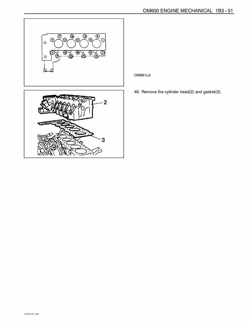
OM661LA
49. Remove the cylinder head(2) and gasket(3).
1B3 -- 52 OM600 ENGINE MECHANICAL
DAEWOOMY_2000
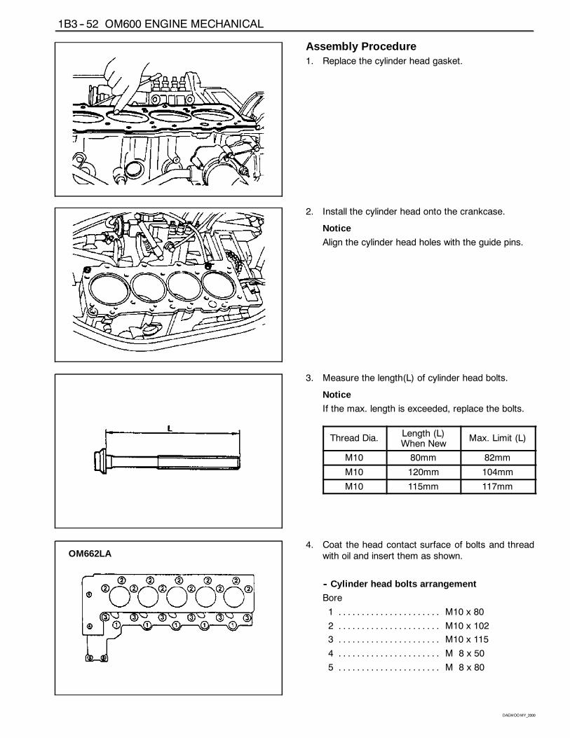
Assembly Procedure1. Replace the cylinder head gasket.
2. Install the cylinder head onto the crankcase.
Notice
Align the cylinder head holes with the guide pins.
3. Measure the length(L) of cylinder head bolts.
Notice
If the max. length is exceeded, replace the bolts.
Thread Dia.Length (L)When New
Max. Limit (L)
M10 80mm 82mm
M10 120mm 104mm
M10 115mm 117mm
OM662LA4. Coat the head contact surface of bolts and thread
with oil and insert them as shown.
-- Cylinder head bolts arrangement
Bore
1 M10 x 80. . . . . . . . . . . . . . . . . . . . . .
2 M10 x 102. . . . . . . . . . . . . . . . . . . . . .
3 M10 x 115. . . . . . . . . . . . . . . . . . . . . .
4 M 8 x 50. . . . . . . . . . . . . . . . . . . . . .
5 M 8 x 80. . . . . . . . . . . . . . . . . . . . . .
OM600 ENGINE MECHANICAL 1B3 -- 53
DAEWOOMY_2000
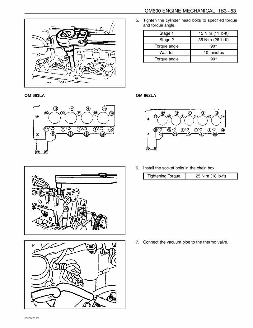
5. Tighten the cylinder head bolts to specified torqueand torque angle.
Stage 1 15 Năm (11 lb-ft)
Stage 2 35 Năm (26 lb-ft)
Torque angle 90_
Wait for 10 minutes
Torque angle 90_
OM 661LA OM 662LA
6. Install the socket bolts in the chain box.
Tightening Torque 25 Năm (18 lb-ft)
7. Connect the vacuum pipe to the thermo valve.
1B3 -- 54 OM600 ENGINE MECHANICAL
DAEWOOMY_2000
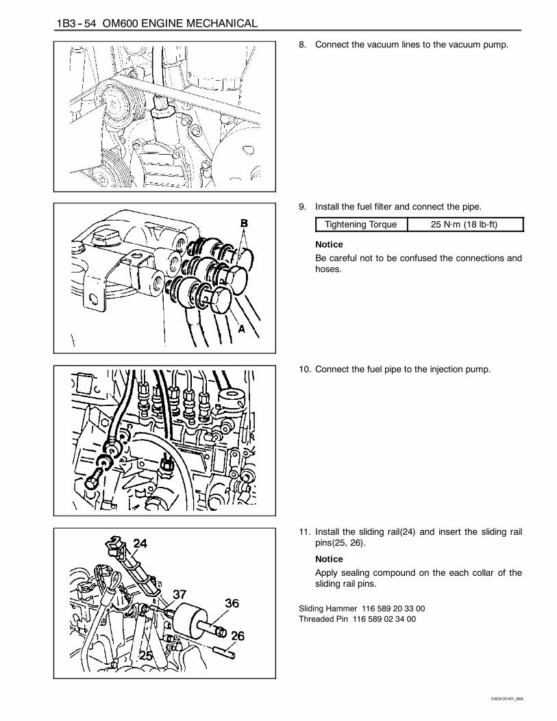
8. Connect the vacuum lines to the vacuum pump.
9. Install the fuel filter and connect the pipe.
Tightening Torque 25 Năm (18 lb-ft)
Notice
Be careful not to be confused the connections andhoses.
10. Connect the fuel pipe to the injection pump.
11. Install the sliding rail(24) and insert the sliding railpins(25, 26).
Notice
Apply sealing compound on the each collar of thesliding rail pins.
Sliding Hammer 116 589 20 33 00
Threaded Pin 116 589 02 34 00
OM600 ENGINE MECHANICAL 1B3 -- 55
DAEWOOMY_2000
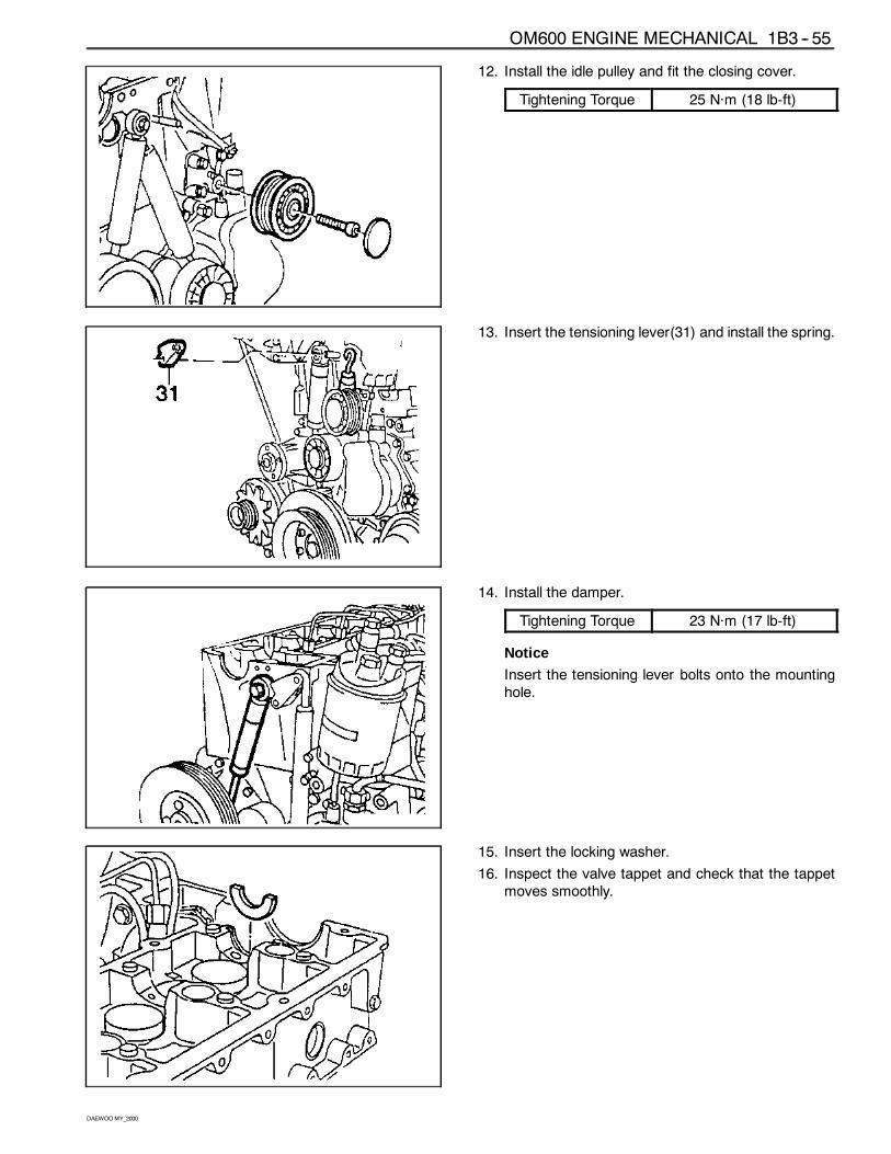
12. Install the idle pulley and fit the closing cover.
Tightening Torque 25 Năm (18 lb-ft)
13. Insert the tensioning lever(31) and install the spring.
14. Install the damper.
Tightening Torque 23 Năm (17 lb-ft)
Notice
Insert the tensioning lever bolts onto the mountinghole.
15. Insert the locking washer.
16. Inspect the valve tappet and check that the tappetmoves smoothly.
1B3 -- 56 OM600 ENGINE MECHANICAL
DAEWOOMY_2000
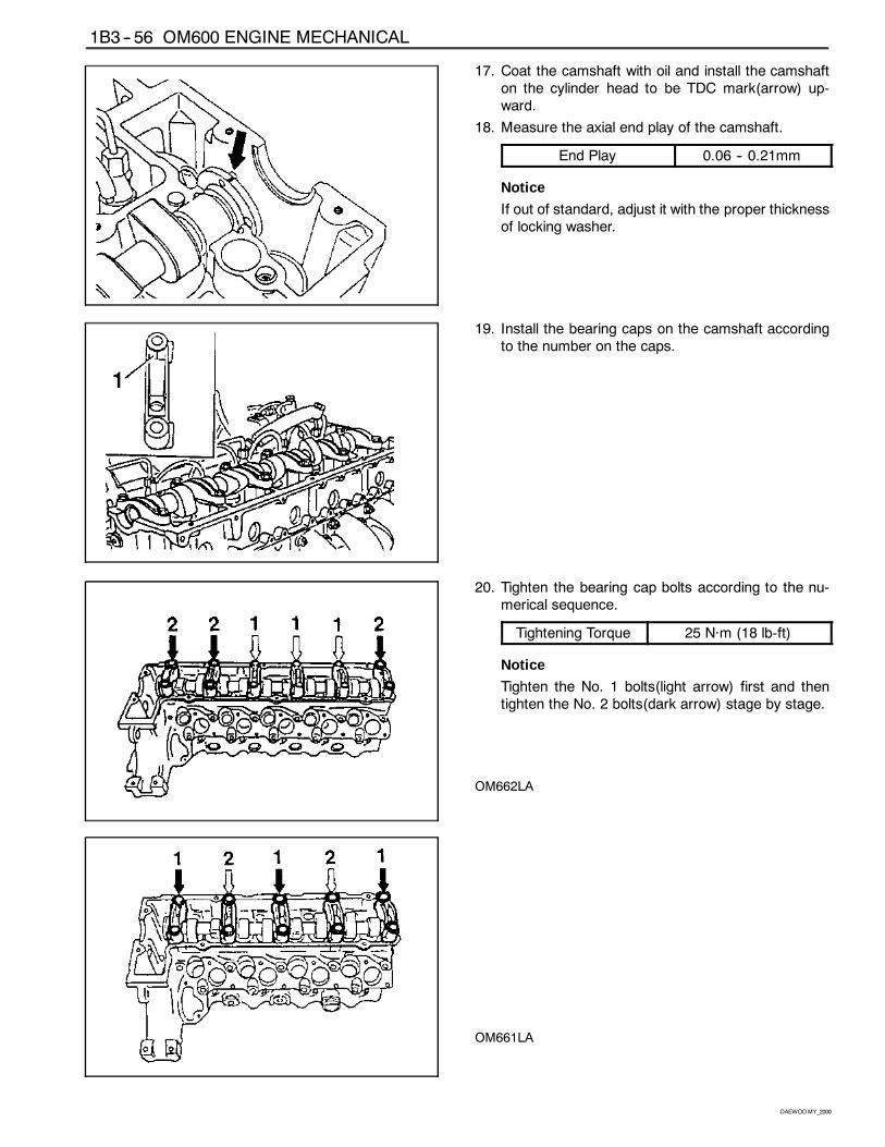
17. Coat the camshaft with oil and install the camshafton the cylinder head to be TDC mark(arrow) up-ward.
18. Measure the axial end play of the camshaft.
End Play 0.06 -- 0.21mm
Notice
If out of standard, adjust it with the proper thicknessof locking washer.
19. Install the bearing caps on the camshaft accordingto the number on the caps.
20. Tighten the bearing cap bolts according to the nu-merical sequence.
Tightening Torque 25 Năm (18 lb-ft)
Notice
Tighten the No. 1 bolts(light arrow) first and thentighten the No. 2 bolts(dark arrow) stage by stage.
OM662LA
OM661LA
OM600 ENGINE MECHANICAL 1B3 -- 57
DAEWOOMY_2000
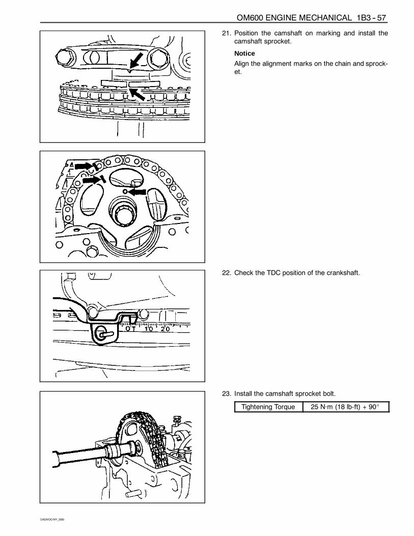
21. Position the camshaft on marking and install thecamshaft sprocket.
Notice
Align the alignment marks on the chain and sprock-et.
22. Check the TDC position of the crankshaft.
23. Install the camshaft sprocket bolt.
Tightening Torque 25 Năm (18 lb-ft) + 90_
1B3 -- 58 OM600 ENGINE MECHANICAL
DAEWOOMY_2000
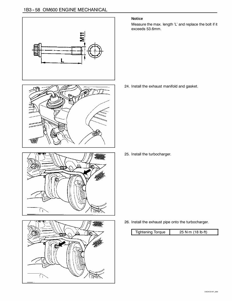
Notice
Measure the max. length ’L’ and replace the bolt if itexceeds 53.6mm.
24. Install the exhaust manifold and gasket.
25. Install the turbocharger.
26. Install the exhaust pipe onto the turbocharger.
Tightening Torque 25 Năm (18 lb-ft)
OM600 ENGINE MECHANICAL 1B3 -- 59
DAEWOOMY_2000
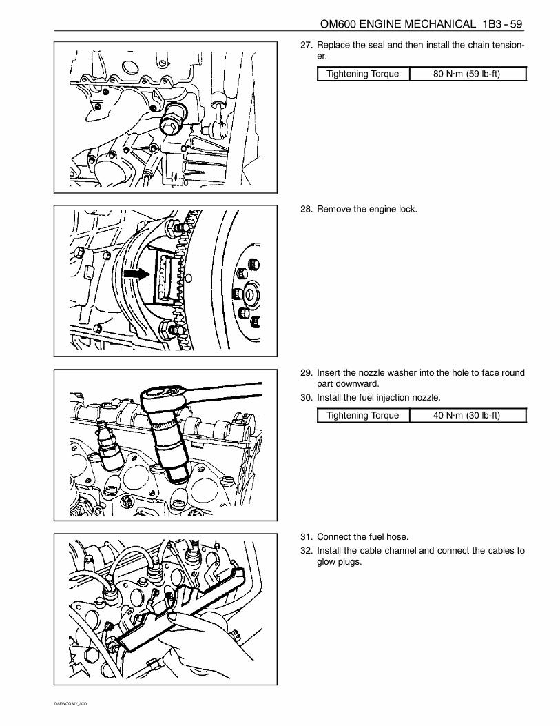
27. Replace the seal and then install the chain tension-er.
Tightening Torque 80 Năm (59 lb-ft)
28. Remove the engine lock.
29. Insert the nozzle washer into the hole to face roundpart downward.
30. Install the fuel injection nozzle.
Tightening Torque 40 Năm (30 lb-ft)
31. Connect the fuel hose.
32. Install the cable channel and connect the cables toglow plugs.
1B3 -- 60 OM600 ENGINE MECHANICAL
DAEWOOMY_2000
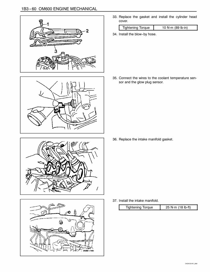
33. Replace the gasket and install the cylinder headcover.
Tightening Torque 10 Năm (89 lb-in)
34. Install the blow--by hose.
35. Connect the wires to the coolant temperature sen-sor and the glow plug sensor.
36. Replace the intake manifold gasket.
37. Install the intake manifold.
Tightening Torque 25 Năm (18 lb-ft)
OM600 ENGINE MECHANICAL 1B3 -- 61
DAEWOOMY_2000
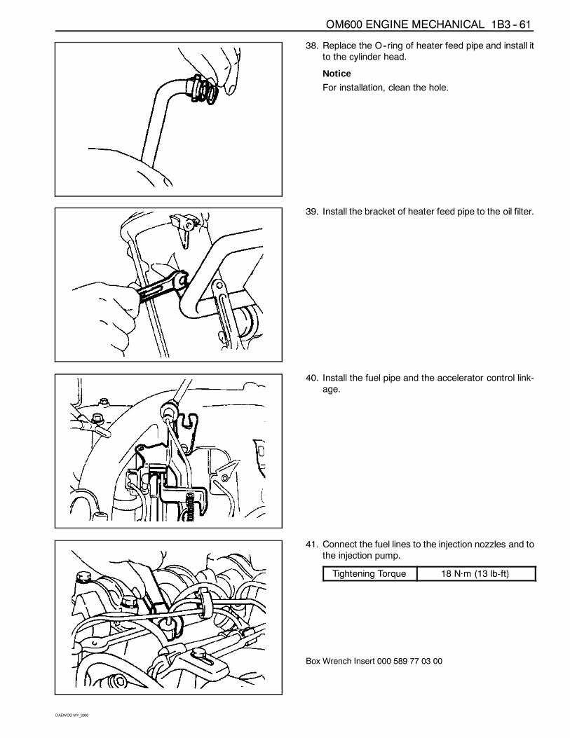
38. Replace the O--ring of heater feed pipe and install itto the cylinder head.
Notice
For installation, clean the hole.
39. Install the bracket of heater feed pipe to the oil filter.
40. Install the fuel pipe and the accelerator control link-age.
41. Connect the fuel lines to the injection nozzles and tothe injection pump.
Tightening Torque 18 Năm (13 lb-ft)
Box Wrench Insert 000 589 77 03 00
1B3 -- 62 OM600 ENGINE MECHANICAL
DAEWOOMY_2000
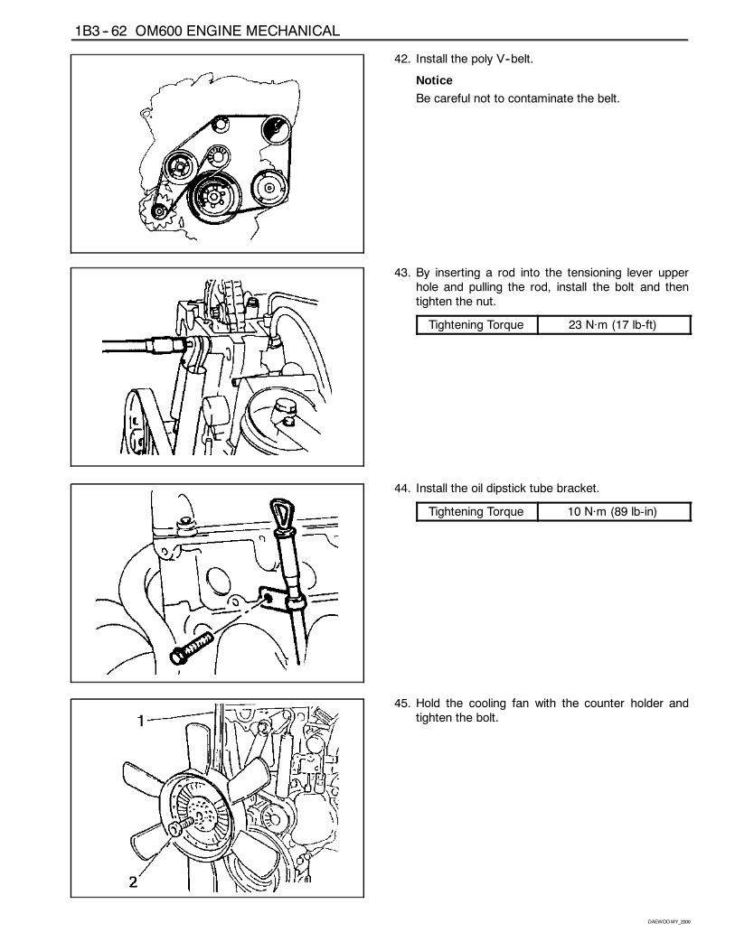
42. Install the poly V--belt.
Notice
Be careful not to contaminate the belt.
43. By inserting a rod into the tensioning lever upperhole and pulling the rod, install the bolt and thentighten the nut.
Tightening Torque 23 Năm (17 lb-ft)
44. Install the oil dipstick tube bracket.
Tightening Torque 10 Năm (89 lb-in)
45. Hold the cooling fan with the counter holder andtighten the bolt.
OM600 ENGINE MECHANICAL 1B3 -- 63
DAEWOOMY_2000
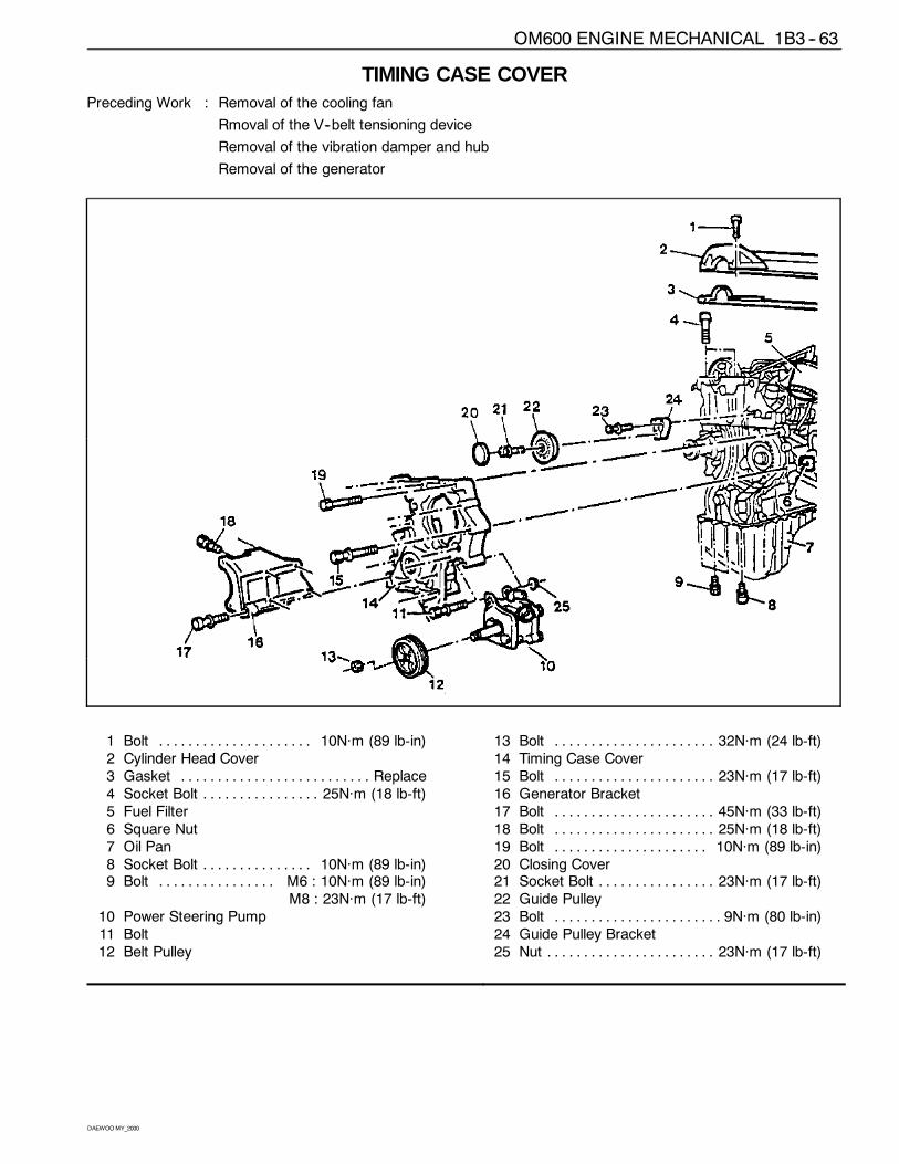
TIMING CASE COVERPreceding Work : Removal of the cooling fan
Rmoval of the V--belt tensioning device
Removal of the vibration damper and hub
Removal of the generator
1 Bolt 10Năm (89 lb-in). . . . . . . . . . . . . . . . . . . . .2 Cylinder Head Cover3 Gasket Replace. . . . . . . . . . . . . . . . . . . . . . . . . .4 Socket Bolt 25Năm (18 lb-ft). . . . . . . . . . . . . . . .5 Fuel Filter6 Square Nut7 Oil Pan8 Socket Bolt 10Năm (89 lb-in). . . . . . . . . . . . . . .9 Bolt M6 : 10Năm (89 lb-in). . . . . . . . . . . . . . . .
M8 : 23Năm (17 lb-ft)10 Power Steering Pump11 Bolt12 Belt Pulley
13 Bolt 32Năm (24 lb-ft). . . . . . . . . . . . . . . . . . . . . .14 Timing Case Cover15 Bolt 23Năm (17 lb-ft). . . . . . . . . . . . . . . . . . . . . .16 Generator Bracket17 Bolt 45Năm (33 lb-ft). . . . . . . . . . . . . . . . . . . . . .18 Bolt 25Năm (18 lb-ft). . . . . . . . . . . . . . . . . . . . . .19 Bolt 10Năm (89 lb-in). . . . . . . . . . . . . . . . . . . . .20 Closing Cover21 Socket Bolt 23Năm (17 lb-ft). . . . . . . . . . . . . . . .22 Guide Pulley23 Bolt 9Năm (80 lb-in). . . . . . . . . . . . . . . . . . . . . . .24 Guide Pulley Bracket25 Nut 23Năm (17 lb-ft). . . . . . . . . . . . . . . . . . . . . . .
1B3 -- 64 OM600 ENGINE MECHANICAL
DAEWOOMY_2000
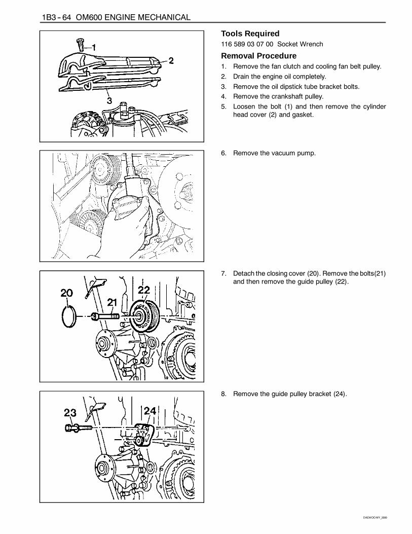
Tools Required116 589 03 07 00 Socket Wrench
Removal Procedure1. Remove the fan clutch and cooling fan belt pulley.
2. Drain the engine oil completely.
3. Remove the oil dipstick tube bracket bolts.
4. Remove the crankshaft pulley.
5. Loosen the bolt (1) and then remove the cylinderhead cover (2) and gasket.
6. Remove the vacuum pump.
7. Detach the closing cover (20). Remove the bolts(21)and then remove the guide pulley (22).
8. Remove the guide pulley bracket (24).
OM600 ENGINE MECHANICAL 1B3 -- 65
DAEWOOMY_2000
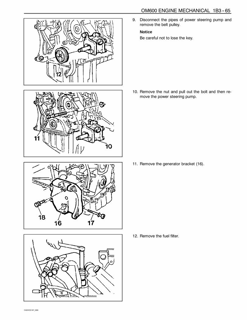
9. Disconnect the pipes of power steering pump andremove the belt pulley.
Notice
Be careful not to lose the key.
10. Remove the nut and pull out the bolt and then re-move the power steering pump.
11. Remove the generator bracket (16).
12. Remove the fuel filter.
1B3 -- 66 OM600 ENGINE MECHANICAL
DAEWOOMY_2000
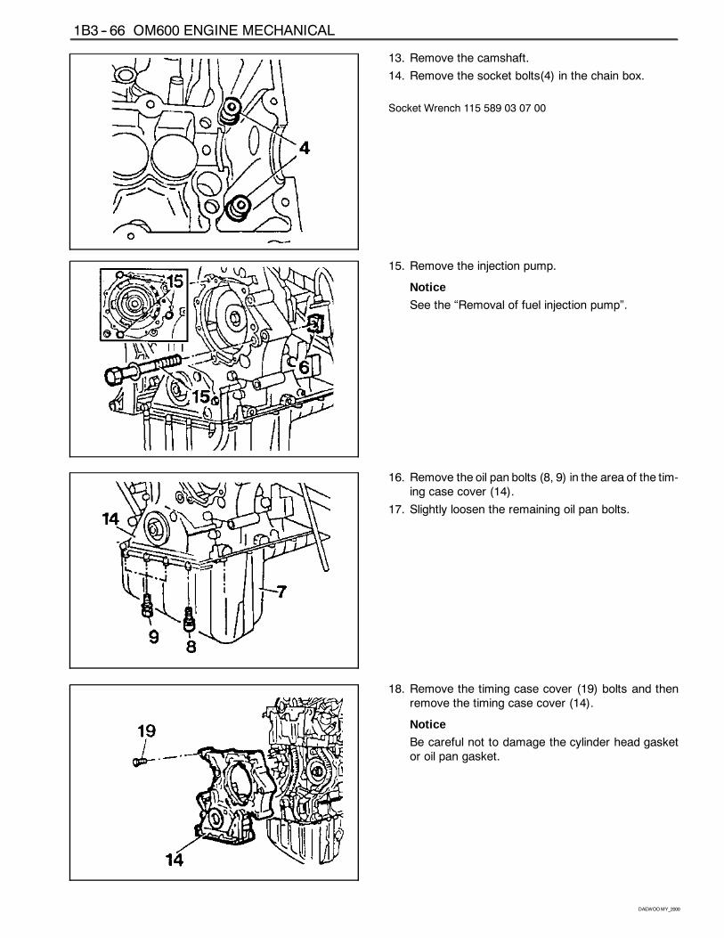
13. Remove the camshaft.
14. Remove the socket bolts(4) in the chain box.
Socket Wrench 115 589 03 07 00
15. Remove the injection pump.
Notice
See the “Removal of fuel injection pump”.
16. Remove the oil pan bolts (8, 9) in the area of the tim-ing case cover (14).
17. Slightly loosen the remaining oil pan bolts.
18. Remove the timing case cover (19) bolts and thenremove the timing case cover (14).
Notice
Be careful not to damage the cylinder head gasketor oil pan gasket.
OM600 ENGINE MECHANICAL 1B3 -- 67
DAEWOOMY_2000
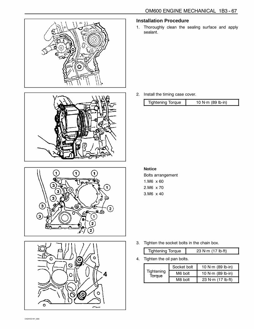
Installation Procedure1. Thoroughly clean the sealing surface and apply
sealant.
2. Install the timing case cover.
Tightening Torque 10 Năm (89 lb-in)
Notice
Bolts arrangement
1.M6 x 60
2.M6 x 70
3.M6 x 40
3. Tighten the socket bolts in the chain box.
Tightening Torque 23 Năm (17 lb-ft)
4. Tighten the oil pan bolts.
Ti h iSocket bolt 10 Năm (89 lb-in)
TighteningTorque
M6 bolt 10 Năm (89 lb-in)Torque
M8 bolt 23 Năm (17 lb-ft)
1B3 -- 68 OM600 ENGINE MECHANICAL
DAEWOOMY_2000
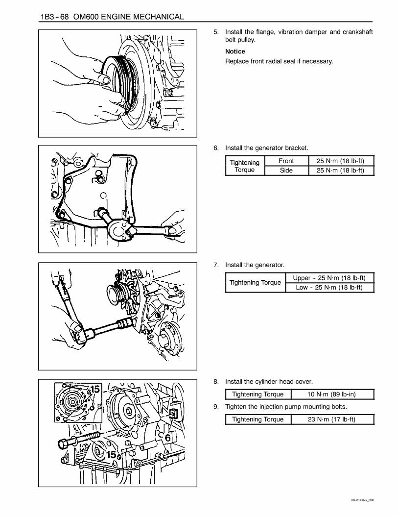
5. Install the flange, vibration damper and crankshaftbelt pulley.
Notice
Replace front radial seal if necessary.
6. Install the generator bracket.
Tightening Front 25 Năm (18 lb-ft)TighteningTorque Side 25 Năm (18 lb-ft)
7. Install the generator.
Tightening TorqueUpper -- 25 Năm (18 lb-ft)
Tightening TorqueLow -- 25 Năm (18 lb-ft)
8. Install the cylinder head cover.
Tightening Torque 10 Năm (89 lb-in)
9. Tighten the injection pump mounting bolts.
Tightening Torque 23 Năm (17 lb-ft)
OM600 ENGINE MECHANICAL 1B3 -- 69
DAEWOOMY_2000
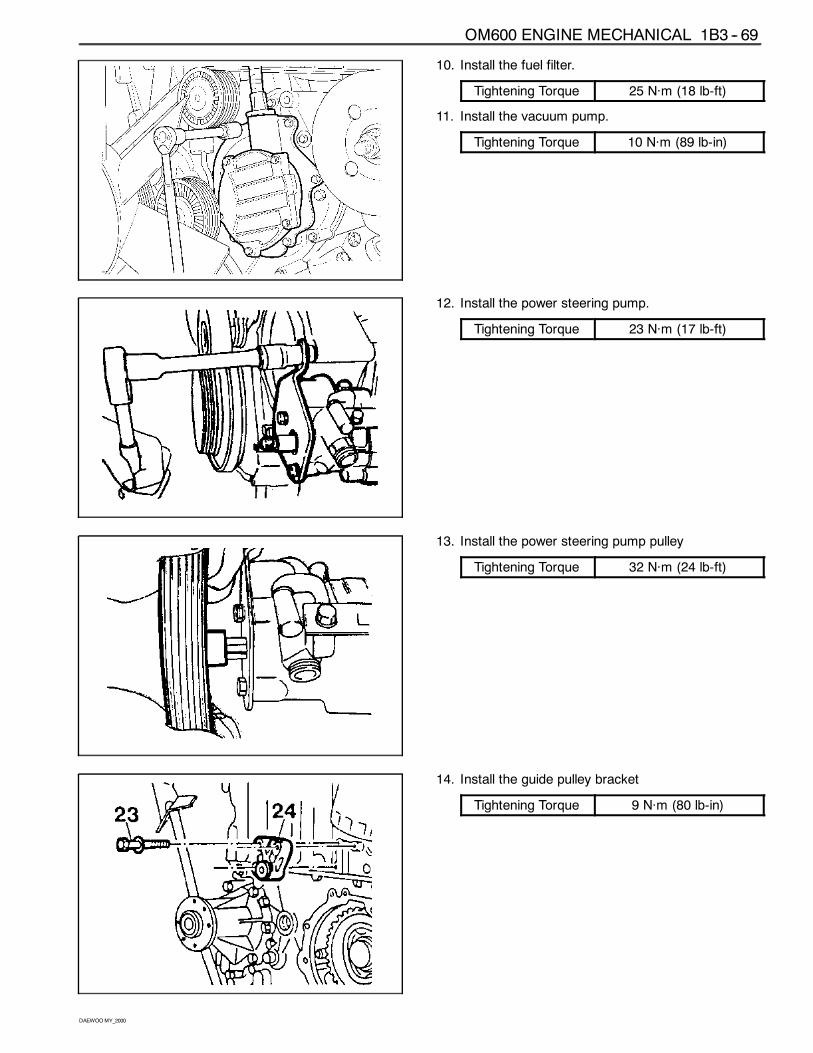
10. Install the fuel filter.
Tightening Torque 25 Năm (18 lb-ft)
11. Install the vacuum pump.
Tightening Torque 10 Năm (89 lb-in)
12. Install the power steering pump.
Tightening Torque 23 Năm (17 lb-ft)
13. Install the power steering pump pulley
Tightening Torque 32 Năm (24 lb-ft)
14. Install the guide pulley bracket
Tightening Torque 9 Năm (80 lb-in)
1B3 -- 70 OM600 ENGINE MECHANICAL
DAEWOOMY_2000
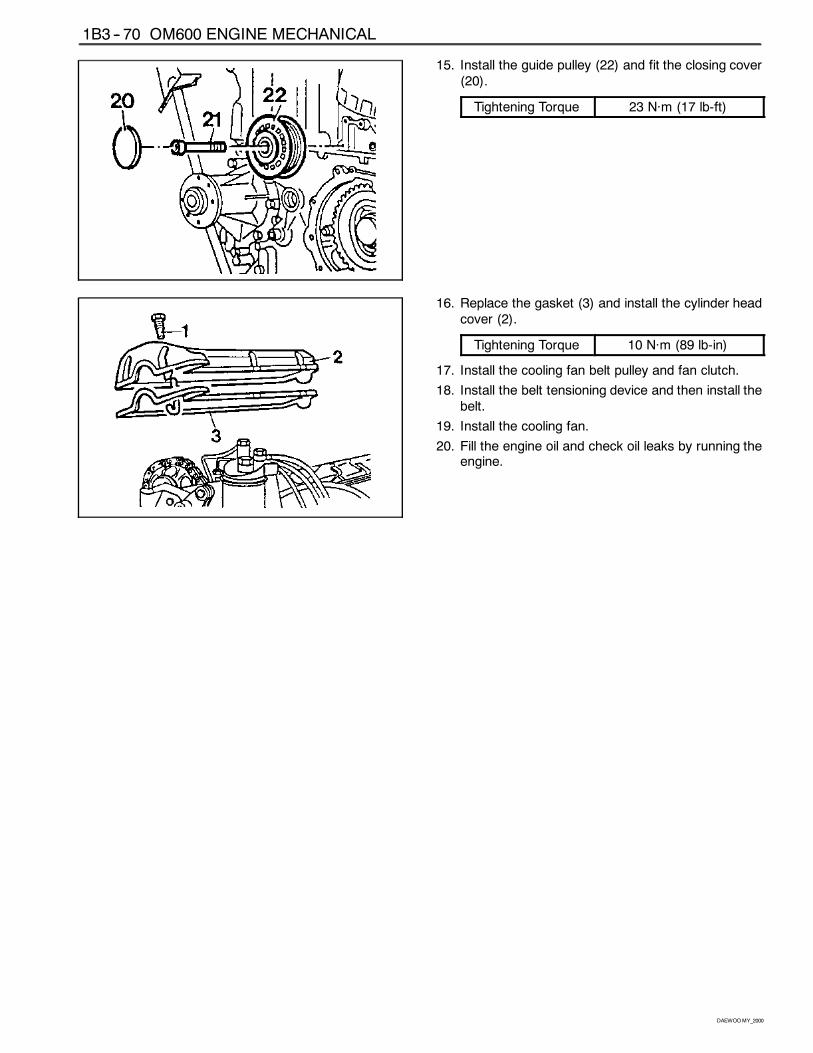
15. Install the guide pulley (22) and fit the closing cover(20).
Tightening Torque 23 Năm (17 lb-ft)
16. Replace the gasket (3) and install the cylinder headcover (2).
Tightening Torque 10 Năm (89 lb-in)
17. Install the cooling fan belt pulley and fan clutch.
18. Install the belt tensioning device and then install thebelt.
19. Install the cooling fan.
20. Fill the engine oil and check oil leaks by running theengine.
OM600 ENGINE MECHANICAL 1B3 -- 71
DAEWOOMY_2000
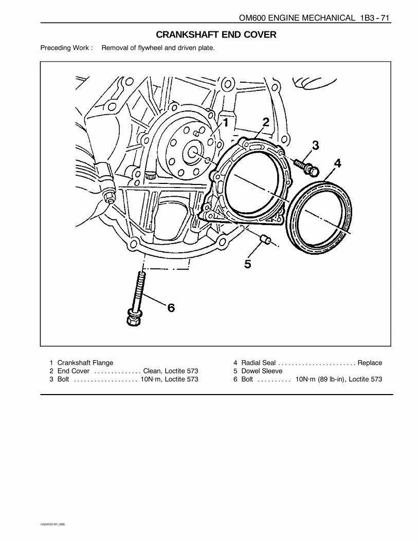
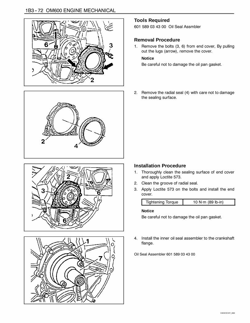
CRANKSHAFT END COVERPreceding Work : Removal of flywheel and driven plate.
1 Crankshaft Flange2 End Cover Clean, Loctite 573. . . . . . . . . . . . . .3 Bolt 10Năm, Loctite 573. . . . . . . . . . . . . . . . . . .
4 Radial Seal Replace. . . . . . . . . . . . . . . . . . . . . . .5 Dowel Sleeve6 Bolt 10Năm (89 lb-in), Loctite 573. . . . . . . . . .
1B3 -- 72 OM600 ENGINE MECHANICAL
DAEWOOMY_2000
Tools Required601 589 03 43 00 Oil Seal Assmbler
Removal Procedure1. Remove the bolts (3, 6) from end cover, By pulling
out the lugs (arrow), remove the cover.
Notice
Be careful not to damage the oil pan gasket.
2. Remove the radial seal (4) with care not to damagethe sealing surface.
Installation Procedure1. Thoroughly clean the sealing surface of end cover
and apply Loctite 573.
2. Clean the groove of radial seal.
3. Apply Loctite 573 on the bolts and install the endcover.
Tightening Torque 10 Năm (89 lb-in)
Notice
Be careful not to damage the oil pan gasket.
4. Install the inner oil seal assembler to the crankshaftflange.
Oil Seal Assembler 601 589 03 43 00
OM600 ENGINE MECHANICAL 1B3 -- 73
DAEWOOMY_2000
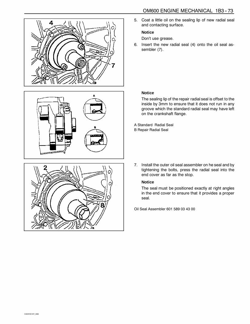
5. Coat a little oil on the sealing lip of new radial sealand contacting surface.
Notice
Don’t use grease.
6. Insert the new radial seal (4) onto the oil seal as-sembler (7).
Notice
The sealing lip of the repair radial seal is offset to theinside by 3mm to ensure that it does not run in anygroove which the standard radial seal may have lefton the crankshaft flange.
A Standard Radial Seal
B Repair Radial Seal
7. Install the outer oil seal assembler on he seal and bytightening the bolts, press the radial seal into theend cover as far as the stop.
Notice
The seal must be positioned exactly at right anglesin the end cover to ensure that it provides a properseal.
Oil Seal Assembler 601 589 03 43 00
1B3 -- 74 OM600 ENGINE MECHANICAL
DAEWOOMY_2000
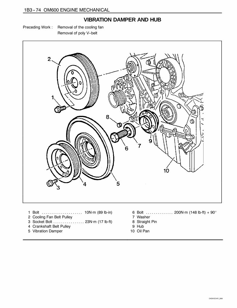
VIBRATION DAMPER AND HUBPreceding Work : Removal of the cooling fan
Removal of poly V--belt
1 Bolt 10Năm (89 lb-in). . . . . . . . . . . . . . . . . . . . .2 Cooling Fan Belt Pulley3 Socket Bolt 23Năm (17 lb-ft). . . . . . . . . . . . . . . .4 Crankshaft Belt Pulley5 Vibration Damper
6 Bolt 200Năm (148 lb-ft) + 90_. . . . . . . . . . . . . .7 Washer8 Straight Pin9 Hub10 Oil Pan
OM600 ENGINE MECHANICAL 1B3 -- 75
DAEWOOMY_2000
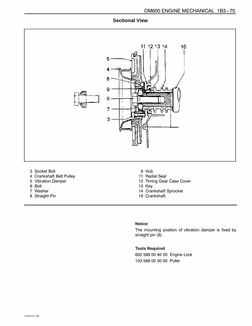
Sectional View
3 Socket Bolt4 Crankshaft Belt Pulley5 Vibration Damper6 Bolt7 Washer8 Straight Pin
9 Hub11 Radial Seal12 Timing Gear Case Cover13 Key14 Crankshaft Sprocket16 Crankshaft
Notice
The mounting position of vibration damper is fixed bystraight pin (8).
Tools Required
602 589 00 40 00 Engine Lock
103 589 00 30 00 Puller
1B3 -- 76 OM600 ENGINE MECHANICAL
DAEWOOMY_2000
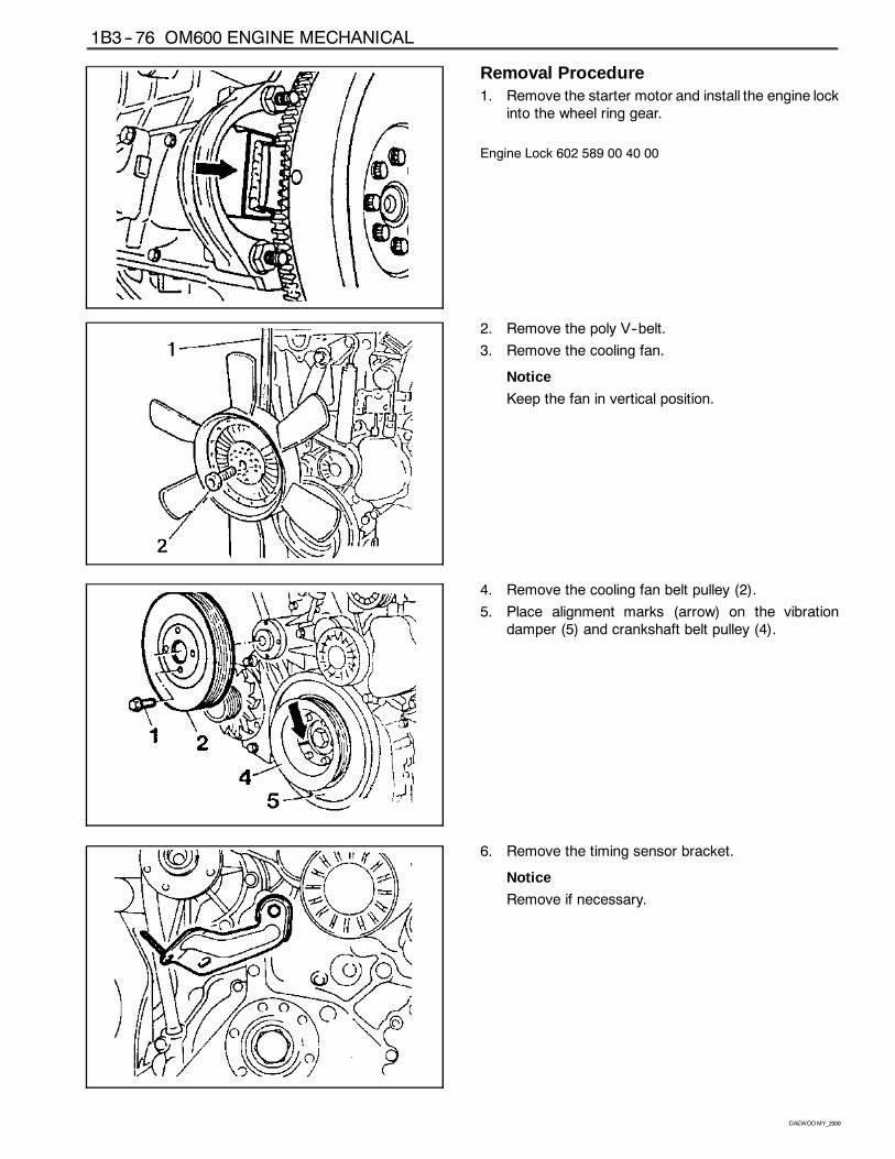
Removal Procedure1. Remove the starter motor and install the engine lock
into the wheel ring gear.
Engine Lock 602 589 00 40 00
2. Remove the poly V--belt.
3. Remove the cooling fan.
Notice
Keep the fan in vertical position.
4. Remove the cooling fan belt pulley (2).
5. Place alignment marks (arrow) on the vibrationdamper (5) and crankshaft belt pulley (4).
6. Remove the timing sensor bracket.
Notice
Remove if necessary.
OM600 ENGINE MECHANICAL 1B3 -- 77
DAEWOOMY_2000
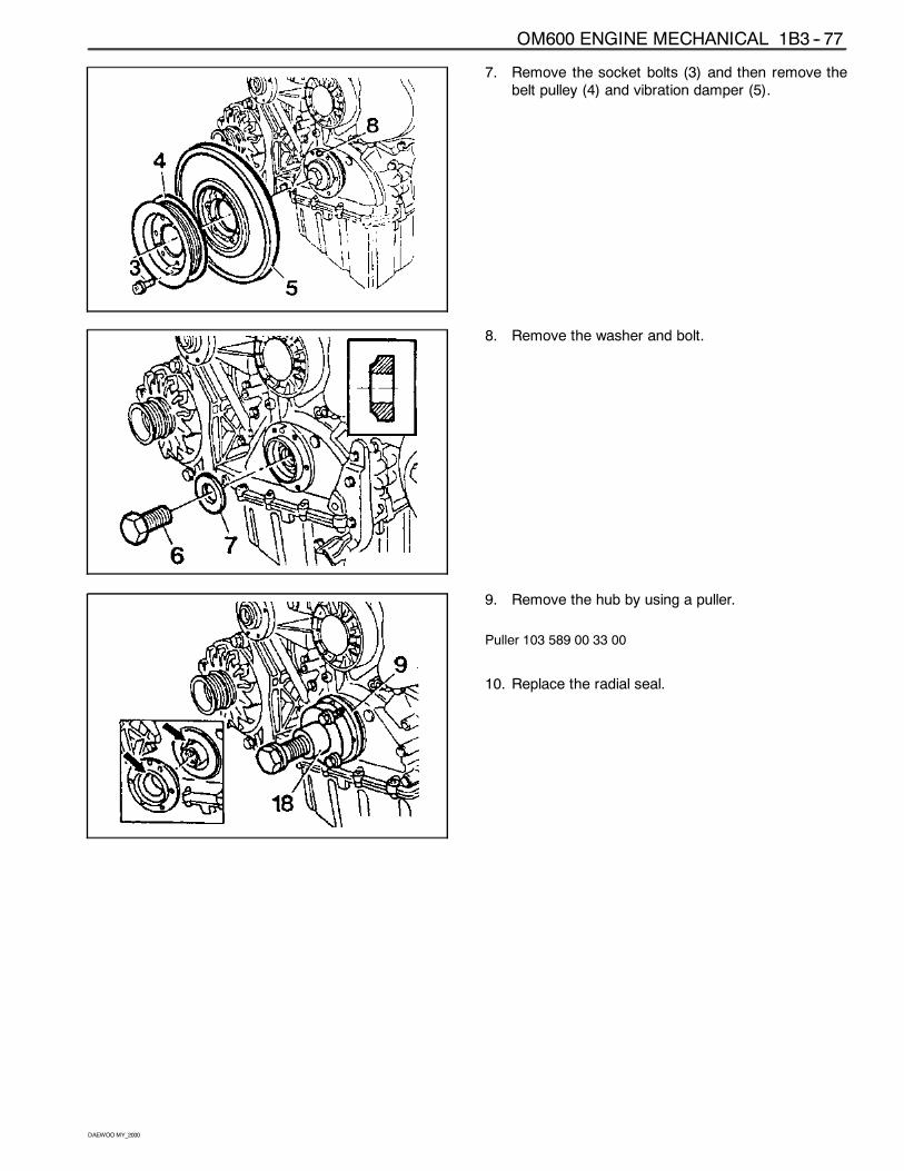
7. Remove the socket bolts (3) and then remove thebelt pulley (4) and vibration damper (5).
8. Remove the washer and bolt.
9. Remove the hub by using a puller.
Puller 103 589 00 33 00
10. Replace the radial seal.
1B3 -- 78 OM600 ENGINE MECHANICAL
DAEWOOMY_2000
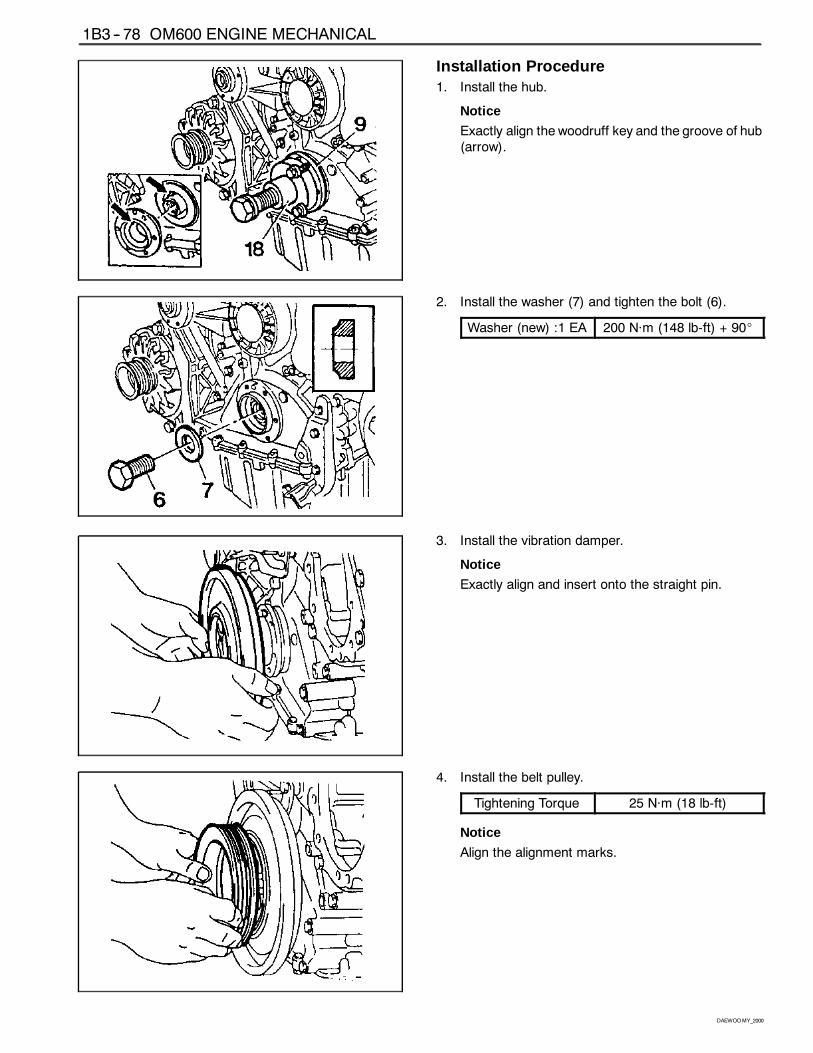
Installation Procedure1. Install the hub.
Notice
Exactly align the woodruff key and the groove of hub(arrow).
2. Install the washer (7) and tighten the bolt (6).
Washer (new) :1 EA 200 Năm (148 lb-ft) + 90_
3. Install the vibration damper.
Notice
Exactly align and insert onto the straight pin.
4. Install the belt pulley.
Tightening Torque 25 Năm (18 lb-ft)
Notice
Align the alignment marks.
OM600 ENGINE MECHANICAL 1B3 -- 79
DAEWOOMY_2000
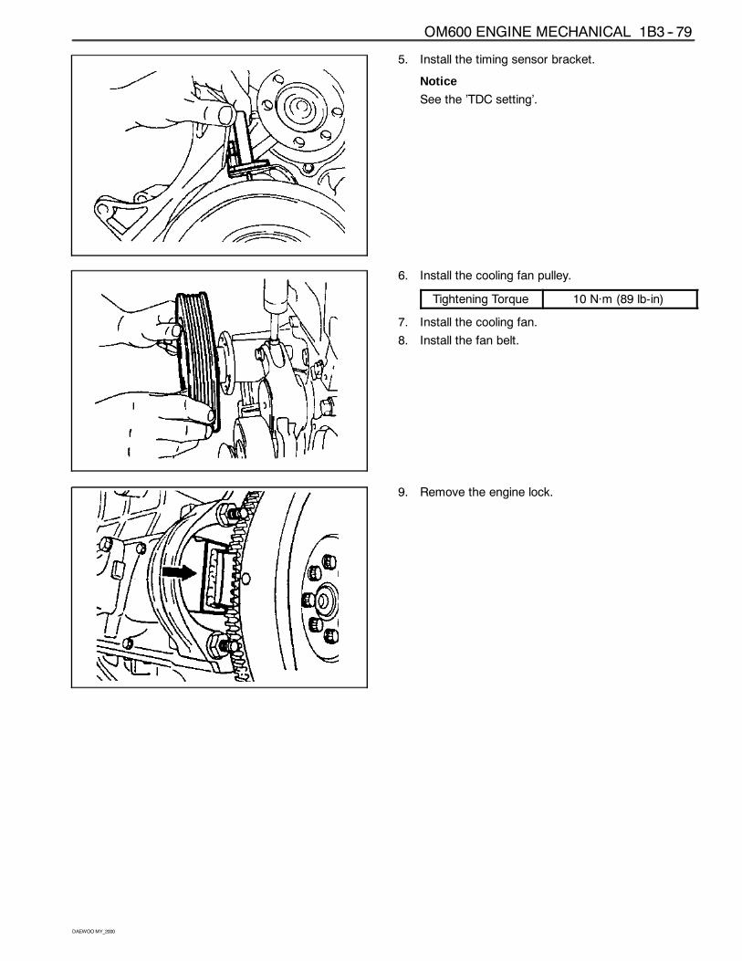
5. Install the timing sensor bracket.
Notice
See the ’TDC setting’.
6. Install the cooling fan pulley.
Tightening Torque 10 Năm (89 lb-in)
7. Install the cooling fan.
8. Install the fan belt.
9. Remove the engine lock.
1B3 -- 80 OM600 ENGINE MECHANICAL
DAEWOOMY_2000
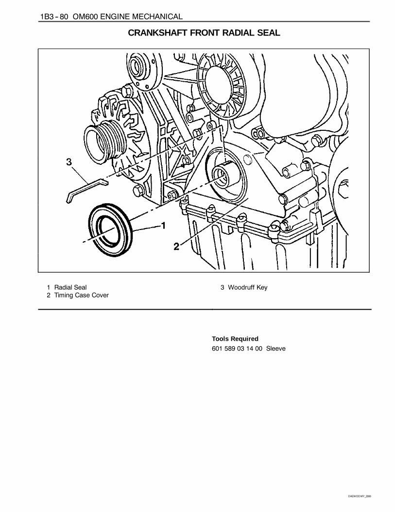
CRANKSHAFT FRONT RADIAL SEAL
1 Radial Seal2 Timing Case Cover
3 Woodruff Key
Tools Required
601 589 03 14 00 Sleeve
OM600 ENGINE MECHANICAL 1B3 -- 81
DAEWOOMY_2000
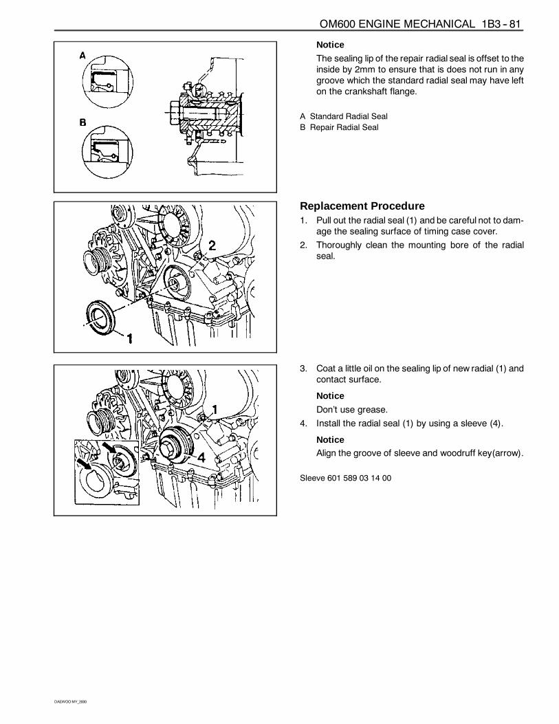
Notice
The sealing lip of the repair radial seal is offset to theinside by 2mm to ensure that is does not run in anygroove which the standard radial seal may have lefton the crankshaft flange.
A Standard Radial Seal
B Repair Radial Seal
Replacement Procedure1. Pull out the radial seal (1) and be careful not to dam-
age the sealing surface of timing case cover.
2. Thoroughly clean the mounting bore of the radialseal.
3. Coat a little oil on the sealing lip of new radial (1) andcontact surface.
Notice
Don’t use grease.
4. Install the radial seal (1) by using a sleeve (4).
NoticeAlign the groove of sleeve and woodruff key(arrow).
Sleeve 601 589 03 14 00
1B3 -- 82 OM600 ENGINE MECHANICAL
DAEWOOMY_2000
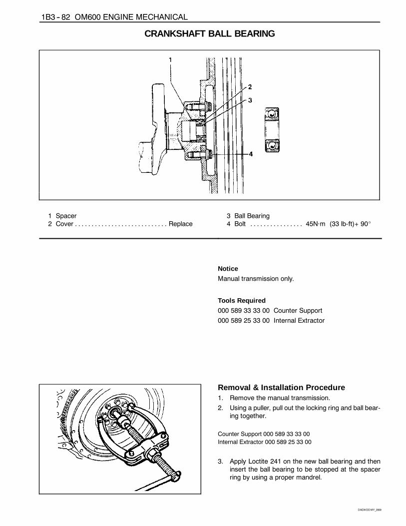
CRANKSHAFT BALL BEARING
1 Spacer2 Cover Replace. . . . . . . . . . . . . . . . . . . . . . . . . . . .
3 Ball Bearing4 Bolt 45Năm (33 lb-ft)+ 90_. . . . . . . . . . . . . . . .
Notice
Manual transmission only.
Tools Required
000 589 33 33 00 Counter Support
000 589 25 33 00 Internal Extractor
Removal & Installation Procedure1. Remove the manual transmission.
2. Using a puller, pull out the locking ring and ball bear-ing together.
Counter Support 000 589 33 33 00
Internal Extractor 000 589 25 33 00
3. Apply Loctite 241 on the new ball bearing and theninsert the ball bearing to be stopped at the spacerring by using a proper mandrel.
OM600 ENGINE MECHANICAL 1B3 -- 83
DAEWOOMY_2000
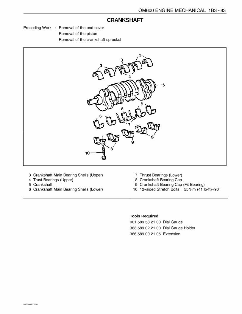
CRANKSHAFTPreceding Work : Removal of the end cover
Removal of the piston
Removal of the crankshaft sprocket
3 Crankshaft Main Bearing Shells (Upper)4 Trust Bearings (Upper)5 Crankshaft6 Crankshaft Main Bearing Shells (Lower)
7 Thrust Bearings (Lower)8 Crankshaft Bearing Cap9 Crankshaft Bearing Cap (Fit Bearing)10 12--sided Stretch Bolts : 55Năm (41 lb-ft)+90_
Tools Required
001 589 53 21 00 Dial Gauge
363 589 02 21 00 Dial Gauge Holder
366 589 00 21 05 Extension
1B3 -- 84 OM600 ENGINE MECHANICAL
DAEWOOMY_2000
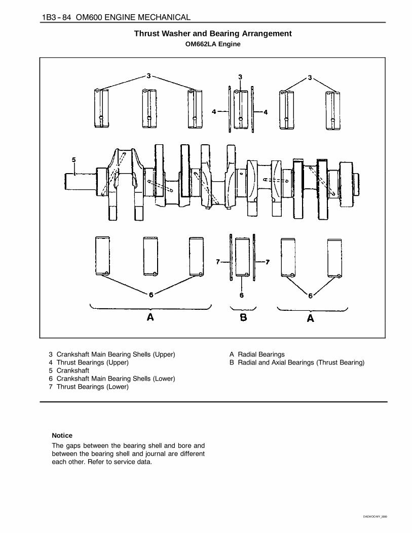
Thrust Washer and Bearing ArrangementOM662LA Engine
3 Crankshaft Main Bearing Shells (Upper)4 Thrust Bearings (Upper)5 Crankshaft6 Crankshaft Main Bearing Shells (Lower)7 Thrust Bearings (Lower)
A Radial BearingsB Radial and Axial Bearings (Thrust Bearing)
Notice
The gaps between the bearing shell and bore andbetween the bearing shell and journal are differenteach other. Refer to service data.
OM600 ENGINE MECHANICAL 1B3 -- 85
DAEWOOMY_2000
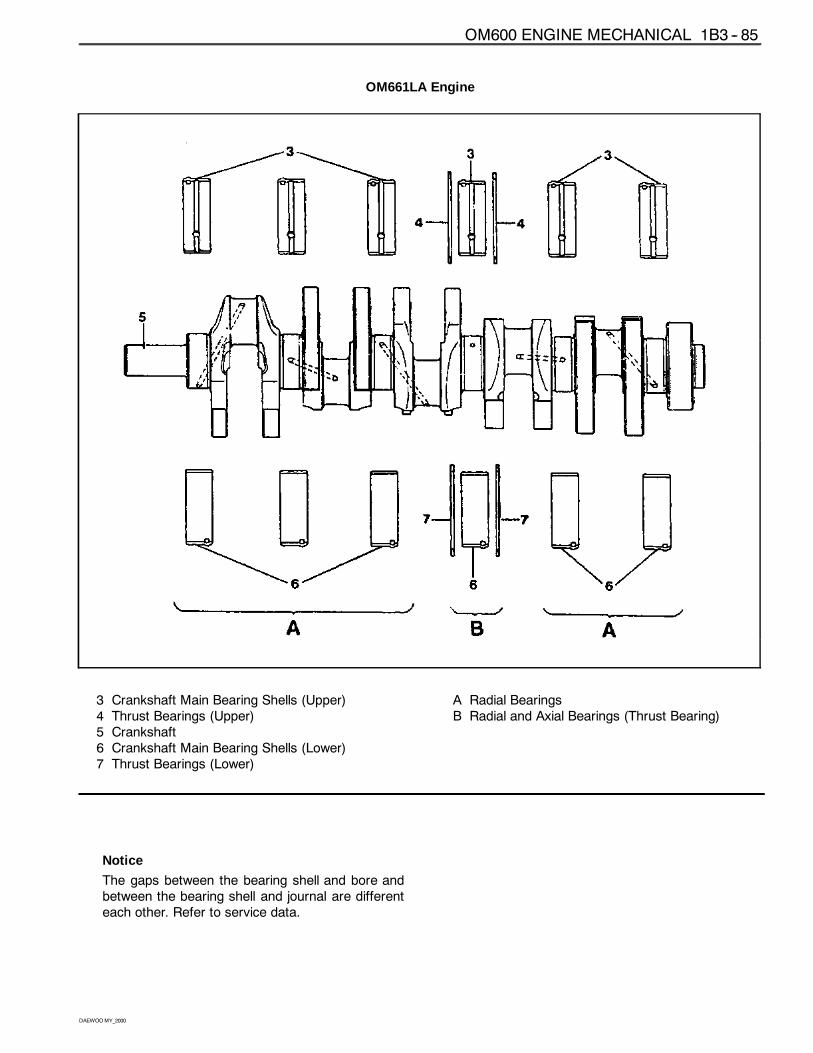
OM661LA Engine
3 Crankshaft Main Bearing Shells (Upper)4 Thrust Bearings (Upper)5 Crankshaft6 Crankshaft Main Bearing Shells (Lower)7 Thrust Bearings (Lower)
A Radial BearingsB Radial and Axial Bearings (Thrust Bearing)
Notice
The gaps between the bearing shell and bore andbetween the bearing shell and journal are differenteach other. Refer to service data.
1B3 -- 86 OM600 ENGINE MECHANICAL
DAEWOOMY_2000
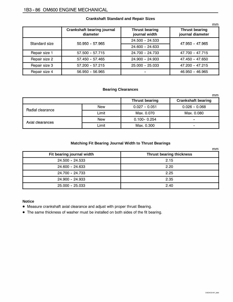
Crankshaft Standard and Repair Sizes
mm
Crankshaft bearing journaldiameter
Thrust bearingjournal width
Thrust bearingjournal diameter
Standard size 50 950 57 96524.500 -- 24.533
47 950 47 965Standard size 50.950 -- 57.96524.600 -- 24.633
47.950 -- 47.965
Repair size 1 57.500 -- 57.715 24.700 -- 24.733 47.700 -- 47.715
Repair size 2 57.450 -- 57.465 24.900 -- 24.933 47.450 -- 47.650
Repair size 3 57.200 -- 57.215 25.000 -- 25.033 47.200 -- 47.215
Repair size 4 56.950 -- 56.965 -- 46.950 -- 46.965
Bearing Clearances
mm
Thrust bearing Crankshaft bearing
Radial clearanceNew 0.027 -- 0.051 0.026 -- 0.068
Radial clearanceLimit Max. 0.070 Max. 0.080
Axial clearancesNew 0.100-- 0.254 --
Axial clearancesLimit Max. 0.300 --
Matching Fit Bearing Journal Width to Thrust Bearings
mm
Fit bearing journal width Thrust bearing thickness
24.500 -- 24.533 2.15
24.600 -- 24.633 2.20
24.700 -- 24.733 2.25
24.900 -- 24.933 2.35
25.000 -- 25.033 2.40
NoticeD Measure crankshaft axial clearance and adjust with proper thrust Bearing.
D The same thickness of washer must be installed on both sides of the fit bearing.
OM600 ENGINE MECHANICAL 1B3 -- 87
DAEWOOMY_2000
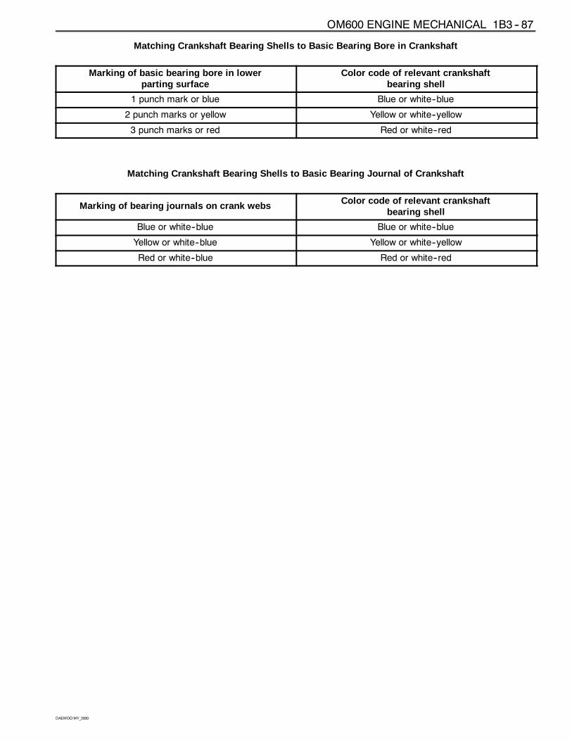
Matching Crankshaft Bearing Shells to Basic Bearing Bore in Crankshaft
Marking of basic bearing bore in lowerparting surface
Color code of relevant crankshaftbearing shell
1 punch mark or blue Blue or white--blue
2 punch marks or yellow Yellow or white--yellow
3 punch marks or red Red or white--red
Matching Crankshaft Bearing Shells to Basic Bearing Journal of Crankshaft
Marking of bearing journals on crank webs Color code of relevant crankshaftbearing shell
Blue or white--blue Blue or white--blue
Yellow or white--blue Yellow or white--yellow
Red or white--blue Red or white--red
1B3 -- 88 OM600 ENGINE MECHANICAL
DAEWOOMY_2000
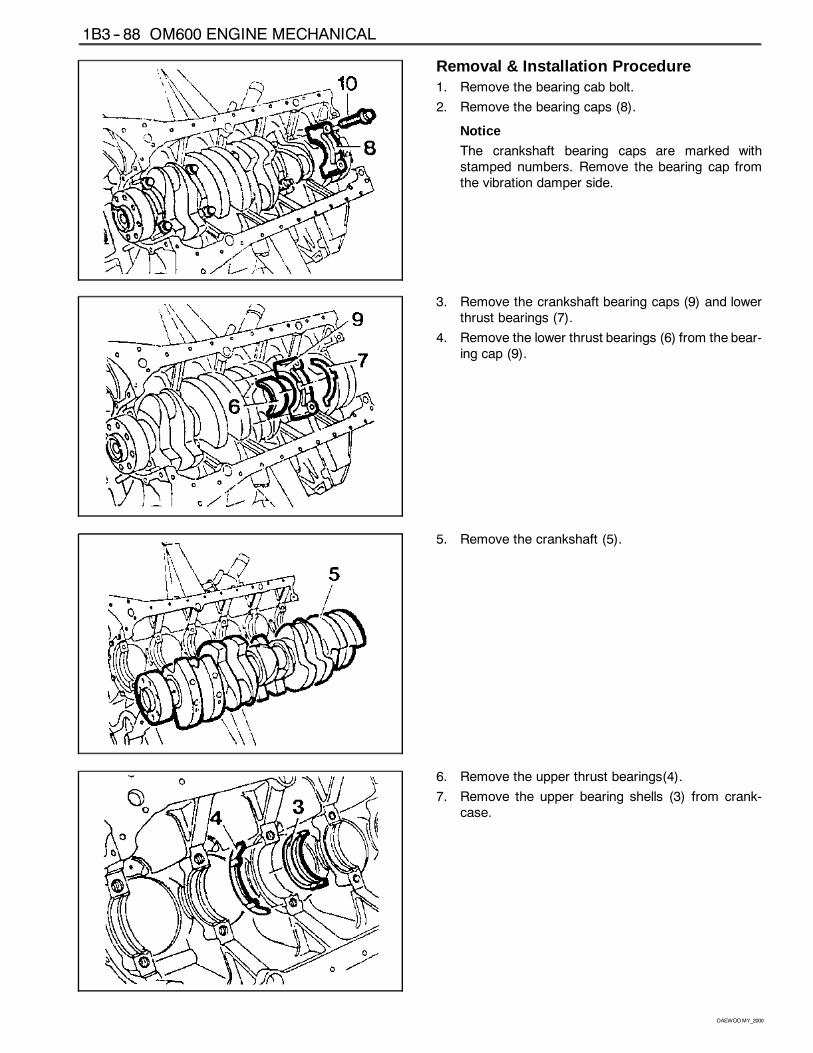
Removal & Installation Procedure1. Remove the bearing cab bolt.
2. Remove the bearing caps (8).
Notice
The crankshaft bearing caps are marked withstamped numbers. Remove the bearing cap fromthe vibration damper side.
3. Remove the crankshaft bearing caps (9) and lowerthrust bearings (7).
4. Remove the lower thrust bearings (6) from the bear-ing cap (9).
5. Remove the crankshaft (5).
6. Remove the upper thrust bearings(4).
7. Remove the upper bearing shells (3) from crank-case.
OM600 ENGINE MECHANICAL 1B3 -- 89
DAEWOOMY_2000
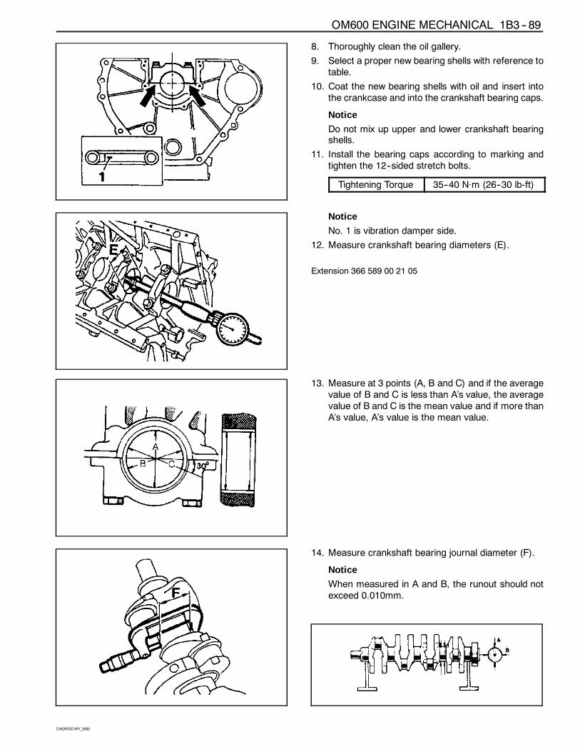
8. Thoroughly clean the oil gallery.
9. Select a proper new bearing shells with reference totable.
10. Coat the new bearing shells with oil and insert intothe crankcase and into the crankshaft bearing caps.
Notice
Do not mix up upper and lower crankshaft bearingshells.
11. Install the bearing caps according to marking andtighten the 12--sided stretch bolts.
Tightening Torque 35--40 Năm (26--30 lb-ft)
Notice
No. 1 is vibration damper side.
12. Measure crankshaft bearing diameters (E).
Extension 366 589 00 21 05
13. Measure at 3 points (A, B and C) and if the averagevalue of B and C is less than A’s value, the averagevalue of B and C is the mean value and if more thanA’s value, A’s value is the mean value.
14. Measure crankshaft bearing journal diameter (F).
Notice
When measured in A and B, the runout should notexceed 0.010mm.
1B3 -- 90 OM600 ENGINE MECHANICAL
DAEWOOMY_2000
15. Measure radial clearance of crankshaft bearing (G).
Clearance ’G’ 0.027 -- 0.051mm
Notice
If ’G’ is out of standard, replace the bearing shellsand adjust the radial clearance of crankshaft bear-ing.
Example) Measured value ’E’ = 57.700mm
Measured value ’F’ = 57.659mm——————————————Clearance ’G’ = 0.041mm
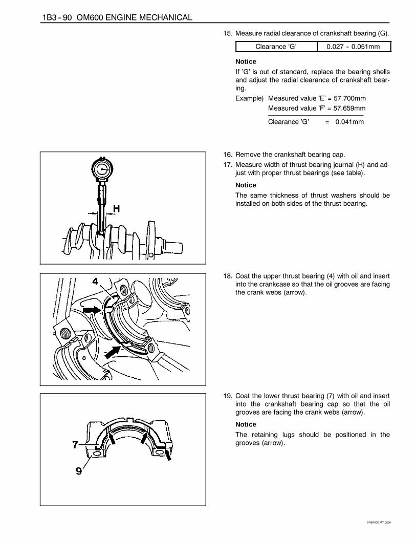
16. Remove the crankshaft bearing cap.
17. Measure width of thrust bearing journal (H) and ad-just with proper thrust bearings (see table).
Notice
The same thickness of thrust washers should beinstalled on both sides of the thrust bearing.
18. Coat the upper thrust bearing (4) with oil and insertinto the crankcase so that the oil grooves are facingthe crank webs (arrow).
19. Coat the lower thrust bearing (7) with oil and insertinto the crankshaft bearing cap so that the oilgrooves are facing the crank webs (arrow).
Notice
The retaining lugs should be positioned in thegrooves (arrow).
OM600 ENGINE MECHANICAL 1B3 -- 91
DAEWOOMY_2000
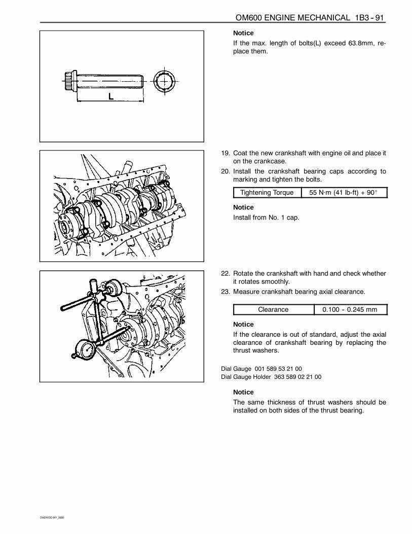
Notice
If the max. length of bolts(L) exceed 63.8mm, re-place them.
19. Coat the new crankshaft with engine oil and place iton the crankcase.
20. Install the crankshaft bearing caps according tomarking and tighten the bolts.
Tightening Torque 55 Năm (41 lb-ft) + 90_
Notice
Install from No. 1 cap.
22. Rotate the crankshaft with hand and check whetherit rotates smoothly.
23. Measure crankshaft bearing axial clearance.
Clearance 0.100 -- 0.245 mm
Notice
If the clearance is out of standard, adjust the axialclearance of crankshaft bearing by replacing thethrust washers.
Dial Gauge 001 589 53 21 00
Dial Gauge Holder 363 589 02 21 00
Notice
The same thickness of thrust washers should beinstalled on both sides of the thrust bearing.
1B3 -- 92 OM600 ENGINE MECHANICAL
DAEWOOMY_2000
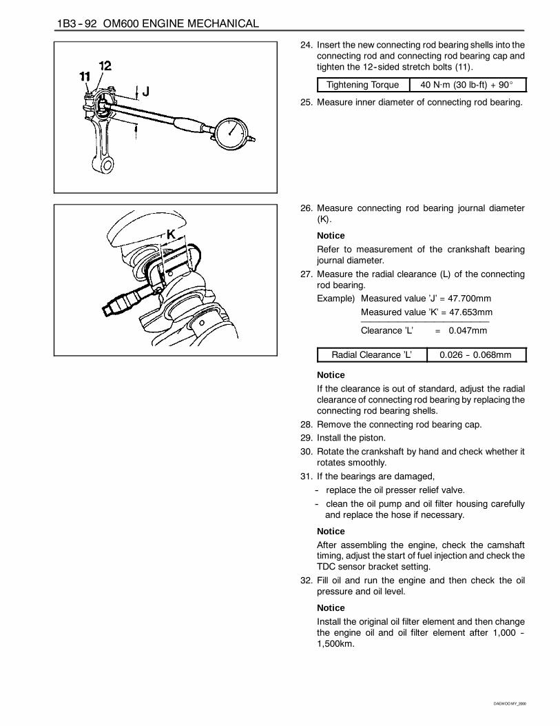
24. Insert the new connecting rod bearing shells into theconnecting rod and connecting rod bearing cap andtighten the 12--sided stretch bolts (11).
Tightening Torque 40 Năm (30 lb-ft) + 90_
25. Measure inner diameter of connecting rod bearing.
26. Measure connecting rod bearing journal diameter(K).
Notice
Refer to measurement of the crankshaft bearingjournal diameter.
27. Measure the radial clearance (L) of the connectingrod bearing.
Example) Measured value ’J’ = 47.700mm
Measured value ’K’ = 47.653mm——————————————Clearance ’L’ = 0.047mm
Radial Clearance ’L’ 0.026 -- 0.068mm
Notice
If the clearance is out of standard, adjust the radialclearance of connecting rod bearing by replacing theconnecting rod bearing shells.
28. Remove the connecting rod bearing cap.
29. Install the piston.
30. Rotate the crankshaft by hand and check whether itrotates smoothly.
31. If the bearings are damaged,
-- replace the oil presser relief valve.
-- clean the oil pump and oil filter housing carefullyand replace the hose if necessary.
Notice
After assembling the engine, check the camshafttiming, adjust the start of fuel injection and check theTDC sensor bracket setting.
32. Fill oil and run the engine and then check the oilpressure and oil level.
Notice
Install the original oil filter element and then changethe engine oil and oil filter element after 1,000 --1,500km.
OM600 ENGINE MECHANICAL 1B3 -- 93
DAEWOOMY_2000
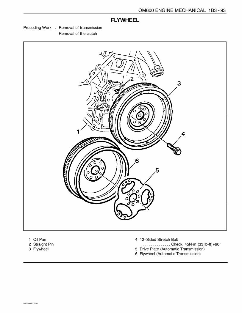
FLYWHEELPreceding Work : Removal of transmission
Removal of the clutch
1 Oil Pan2 Straight Pin3 Flywheel
4 12--Sided Stretch BoltCheck, 45Năm (33 lb-ft)+90_. . . . . . . . . . . . . . .
5 Drive Plate (Automatic Transmission)6 Flywheel (Automatic Transmission)
1B3 -- 94 OM600 ENGINE MECHANICAL
DAEWOOMY_2000
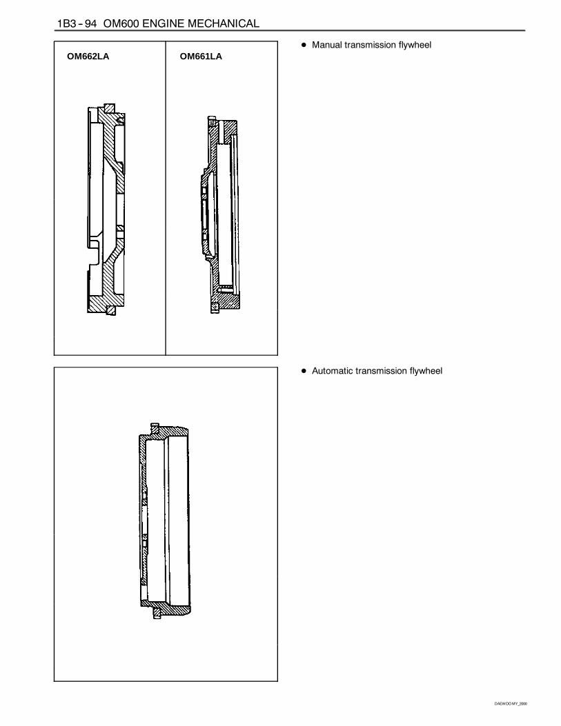
OM662LA OM661LAD Manual transmission flywheel
D Automatic transmission flywheel
OM600 ENGINE MECHANICAL 1B3 -- 95
DAEWOOMY_2000
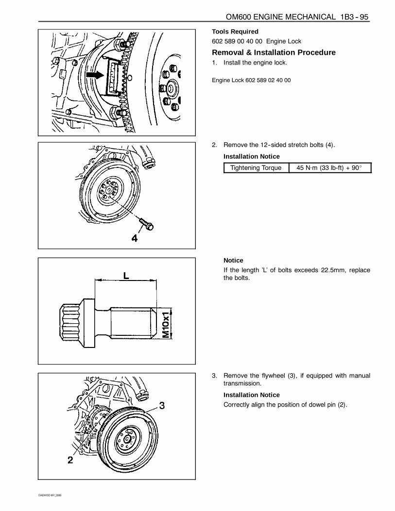
Tools Required
602 589 00 40 00 Engine Lock
Removal & Installation Procedure1. Install the engine lock.
Engine Lock 602 589 02 40 00
2. Remove the 12--sided stretch bolts (4).
Installation Notice
Tightening Torque 45 Năm (33 lb-ft) + 90_
Notice
If the length ’L’ of bolts exceeds 22.5mm, replacethe bolts.
3. Remove the flywheel (3), if equipped with manualtransmission.
Installation Notice
Correctly align the position of dowel pin (2).
1B3 -- 96 OM600 ENGINE MECHANICAL
DAEWOOMY_2000
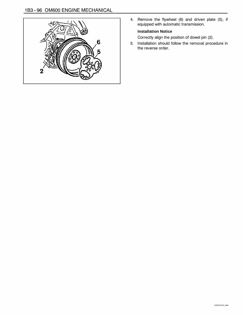
4. Remove the flywheel (6) and driven plate (5), ifequipped with automatic transmission.
Installation Notice
Correctly align the position of dowel pin (2).
5. Installation should follow the removal procedure inthe reverse order.
OM600 ENGINE MECHANICAL 1B3 -- 97
DAEWOOMY_2000
MACHINING OF FLYWHEEL
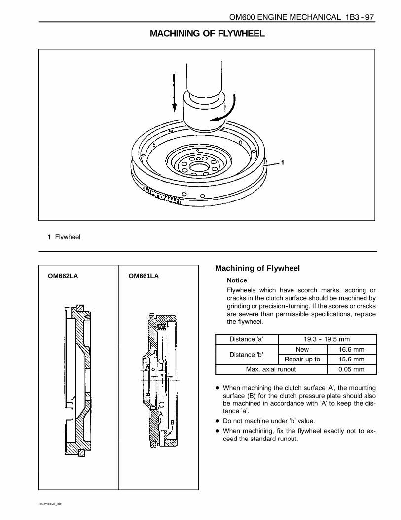
1 Flywheel
OM662LA OM661LAMachining of Flywheel
Notice
Flywheels which have scorch marks, scoring orcracks in the clutch surface should be machined bygrinding or precision--turning. If the scores or cracksare severe than permissible specifications, replacethe flywheel.
Distance ’a’ 19.3 -- 19.5 mm
Distance ’b’New 16.6 mm
Distance ’b’Repair up to 15.6 mm
Max. axial runout 0.05 mm
D When machining the clutch surface ’A’, the mountingsurface (B) for the clutch pressure plate should alsobe machined in accordance with ’A’ to keep the dis-tance ’a’.
D Do not machine under ’b’ value.
D When machining, fix the flywheel exactly not to ex-ceed the standard runout.
1B3 -- 98 OM600 ENGINE MECHANICAL
DAEWOOMY_2000
FLYWHEEL RING GEARPreceding Work : Removal of flywheel
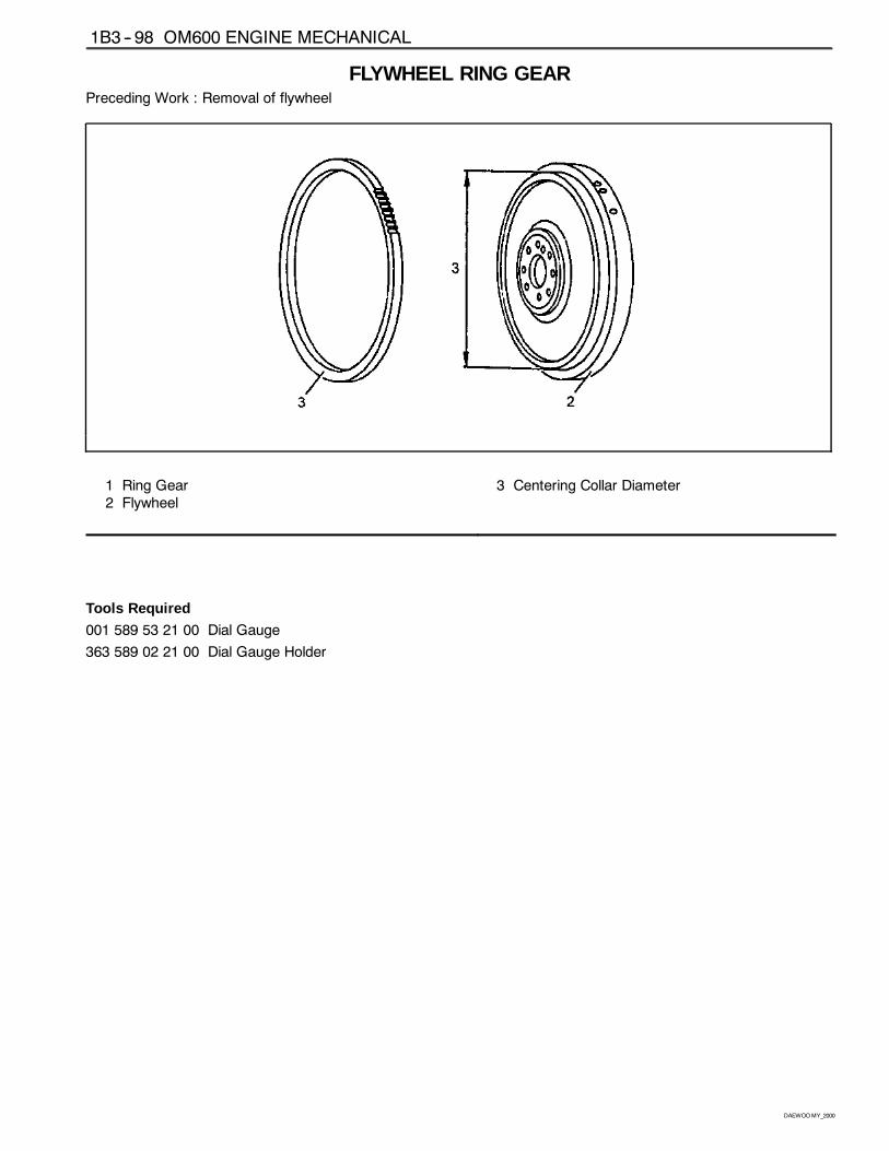
1 Ring Gear2 Flywheel
3 Centering Collar Diameter
Tools Required
001 589 53 21 00 Dial Gauge
363 589 02 21 00 Dial Gauge Holder
OM600 ENGINE MECHANICAL 1B3 -- 99
DAEWOOMY_2000
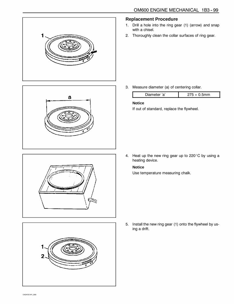
Replacement Procedure1. Drill a hole into the ring gear (1) (arrow) and snap
with a chisel.
2. Thoroughly clean the collar surfaces of ring gear.
3. Measure diameter (a) of centering collar.
Diameter ’a’ 275 + 0.5mm
Notice
If out of standard, replace the flywheel.
4. Heat up the new ring gear up to 220_C by using aheating device.
Notice
Use temperature measuring chalk.
5. Install the new ring gear (1) onto the flywheel by us-ing a drift.
1B3 -- 100 OM600 ENGINE MECHANICAL
DAEWOOMY_2000
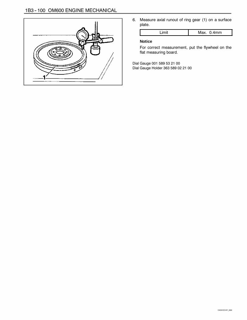
6. Measure axial runout of ring gear (1) on a surfaceplate.
Limit Max. 0.4mm
Notice
For correct measurement, put the flywheel on theflat measuring board.
Dial Gauge 001 589 53 21 00
Dial Gauge Holder 363 589 02 21 00
OM600 ENGINE MECHANICAL 1B3 -- 101
DAEWOOMY_2000
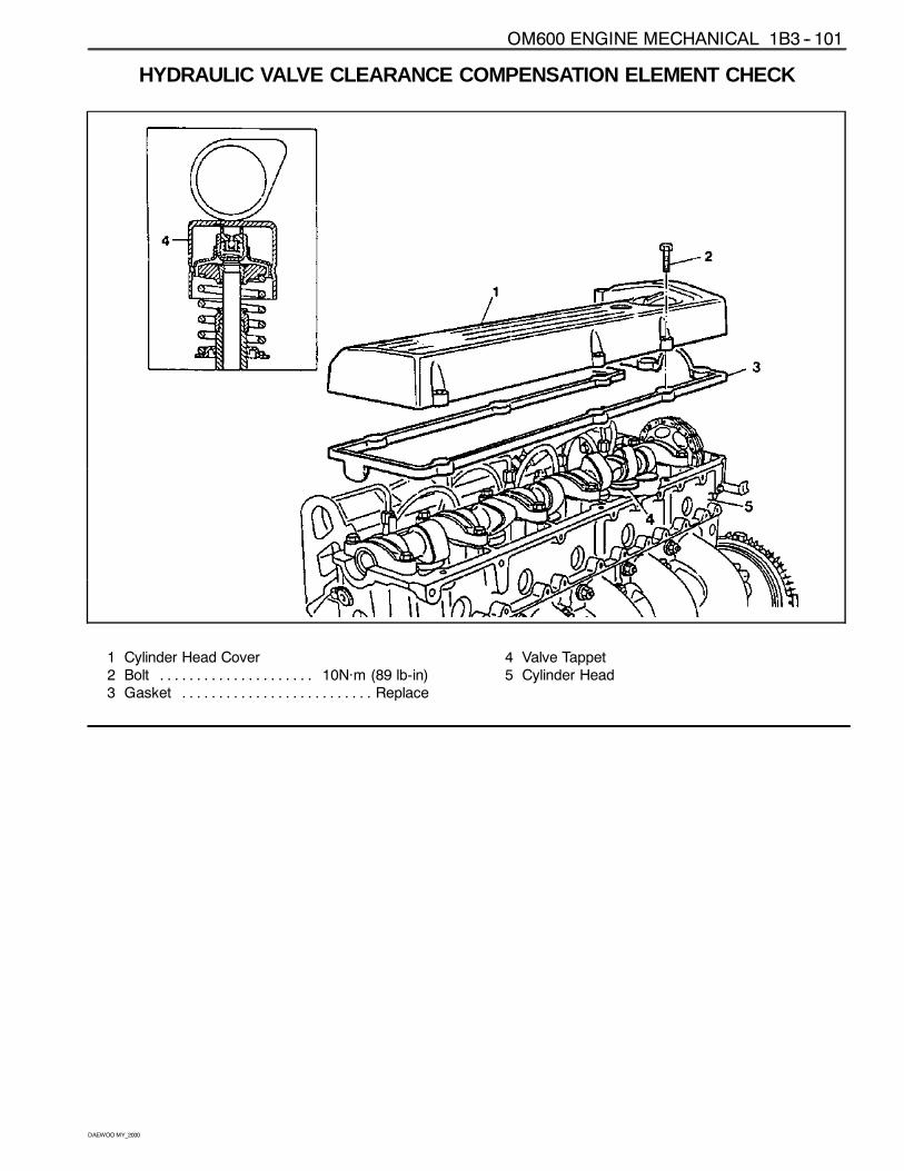
HYDRAULIC VALVE CLEARANCE COMPENSATION ELEMENT CHECK
1 Cylinder Head Cover2 Bolt 10Năm (89 lb-in). . . . . . . . . . . . . . . . . . . . .3 Gasket Replace. . . . . . . . . . . . . . . . . . . . . . . . . .
4 Valve Tappet5 Cylinder Head
1B3 -- 102 OM600 ENGINE MECHANICAL
DAEWOOMY_2000
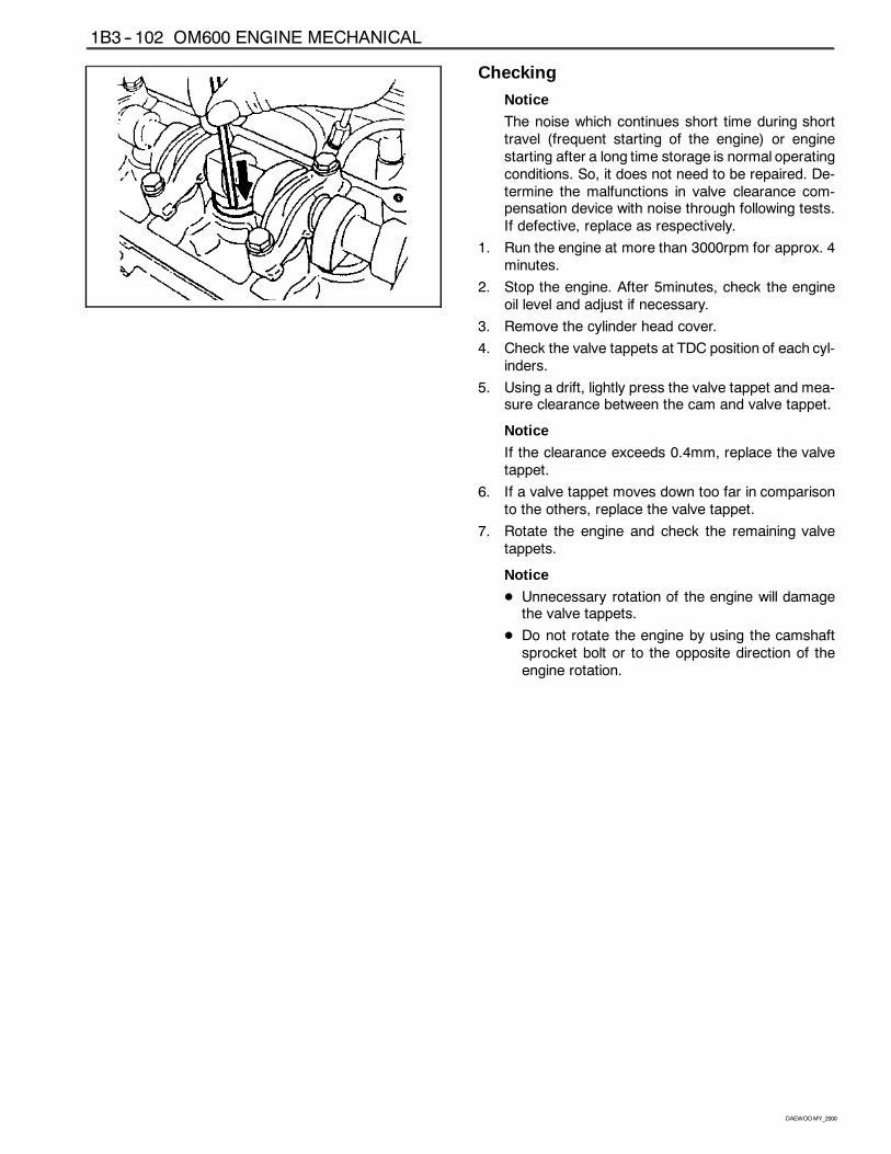
Checking
Notice
The noise which continues short time during shorttravel (frequent starting of the engine) or enginestarting after a long time storage is normal operatingconditions. So, it does not need to be repaired. De-termine the malfunctions in valve clearance com-pensation device with noise through following tests.If defective, replace as respectively.
1. Run the engine at more than 3000rpm for approx. 4minutes.
2. Stop the engine. After 5minutes, check the engineoil level and adjust if necessary.
3. Remove the cylinder head cover.
4. Check the valve tappets at TDC position of each cyl-inders.
5. Using a drift, lightly press the valve tappet and mea-sure clearance between the cam and valve tappet.
Notice
If the clearance exceeds 0.4mm, replace the valvetappet.
6. If a valve tappet moves down too far in comparisonto the others, replace the valve tappet.
7. Rotate the engine and check the remaining valvetappets.
Notice
D Unnecessary rotation of the engine will damagethe valve tappets.
D Do not rotate the engine by using the camshaftsprocket bolt or to the opposite direction of theengine rotation.
OM600 ENGINE MECHANICAL 1B3 -- 103
DAEWOOMY_2000
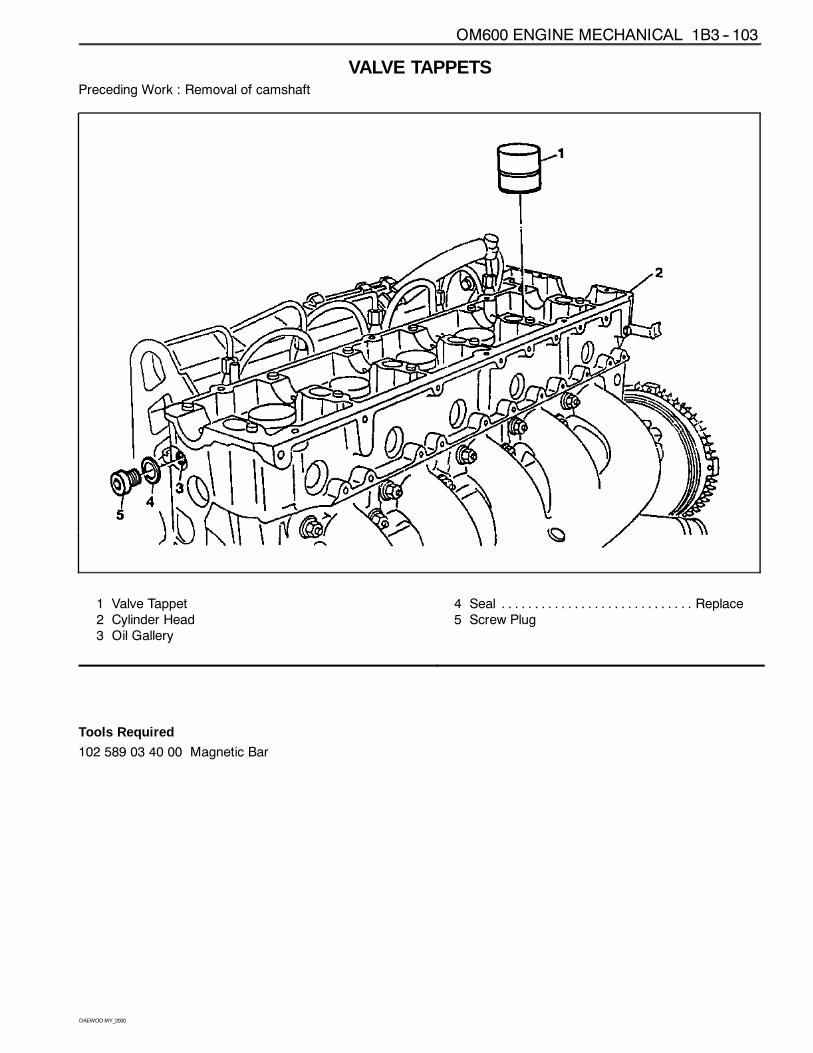
VALVE TAPPETSPreceding Work : Removal of camshaft
1 Valve Tappet2 Cylinder Head3 Oil Gallery
4 Seal Replace. . . . . . . . . . . . . . . . . . . . . . . . . . . . .5 Screw Plug
Tools Required
102 589 03 40 00 Magnetic Bar
1B3 -- 104 OM600 ENGINE MECHANICAL
DAEWOOMY_2000
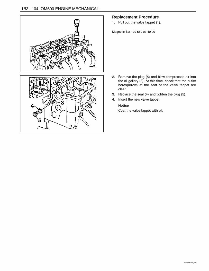
Replacement Procedure1. Pull out the valve tappet (1).
Magnetic Bar 102 589 03 40 00
2. Remove the plug (5) and blow compressed air intothe oil gallery (3). At this time, check that the outletbores(arrow) at the seat of the valve tappet areclear.
3. Replace the seal (4) and tighten the plug (5).
4. Insert the new valve tappet.
NoticeCoat the valve tappet with oil.
OM600 ENGINE MECHANICAL 1B3 -- 105
DAEWOOMY_2000
VALVE SPRINGS CHECKPreceding Work : Removal of valve spring
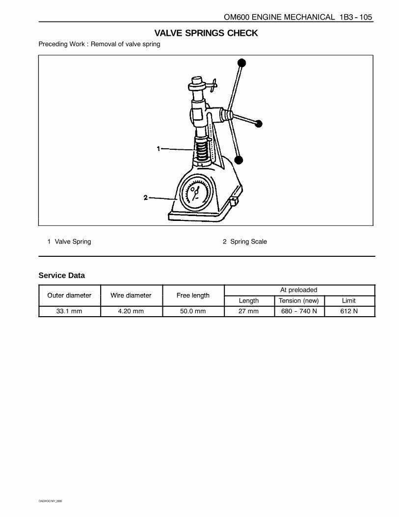
1 Valve Spring 2 Spring Scale
Service Data
Outer diameter Wire diameter Free lengthAt preloaded
Outer diameter Wire diameter Free lengthLength Tension (new) Limit
33.1 mm 4.20 mm 50.0 mm 27 mm 680 -- 740 N 612 N
1B3 -- 106 OM600 ENGINE MECHANICAL
DAEWOOMY_2000
VALVE SPRINGS (CYLINDER HEAD REMOVED)Cylinder Head Removed
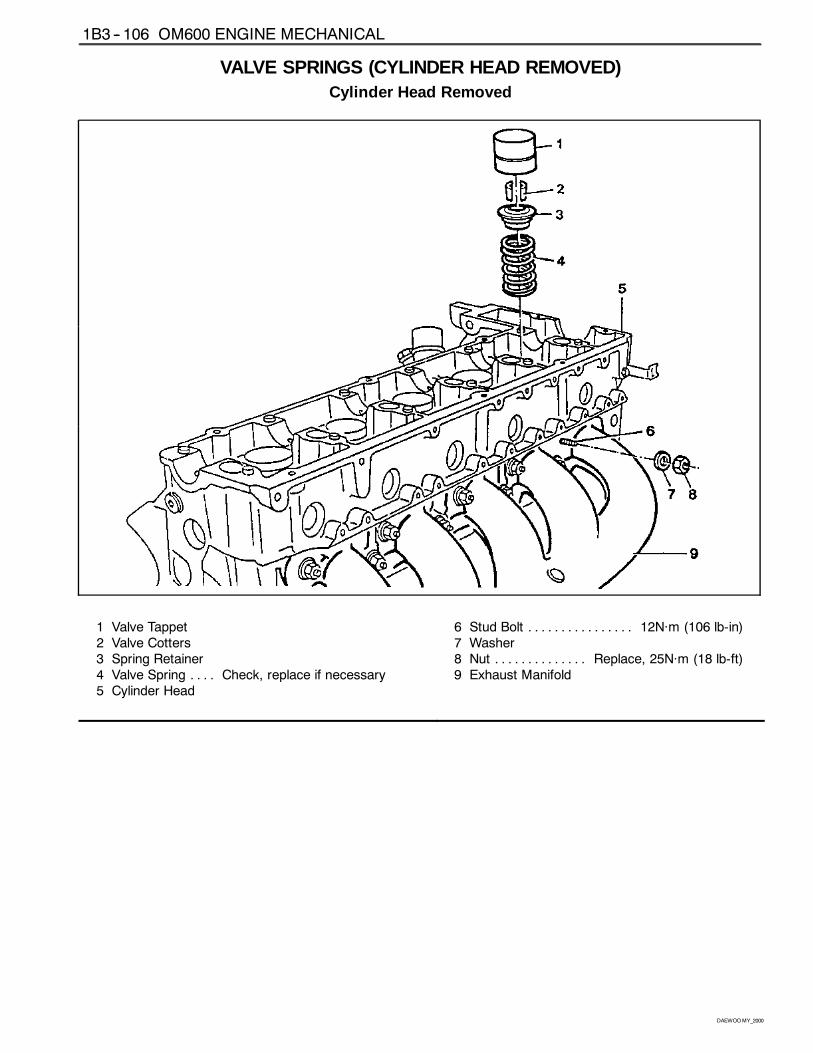
1 Valve Tappet2 Valve Cotters3 Spring Retainer4 Valve Spring Check, replace if necessary. . . .5 Cylinder Head
6 Stud Bolt 12Năm (106 lb-in). . . . . . . . . . . . . . . .7 Washer8 Nut Replace, 25Năm (18 lb-ft). . . . . . . . . . . . . .9 Exhaust Manifold
OM600 ENGINE MECHANICAL 1B3 -- 107
DAEWOOMY_2000
Tools Required
102 589 03 40 00 Magnetic Bar
116 589 06 63 00 Magnetic Finger
601 589 01 59 00 Assembling Board
601 589 02 59 00 Supporting Bridge
667 589 00 31 00 Press Lever
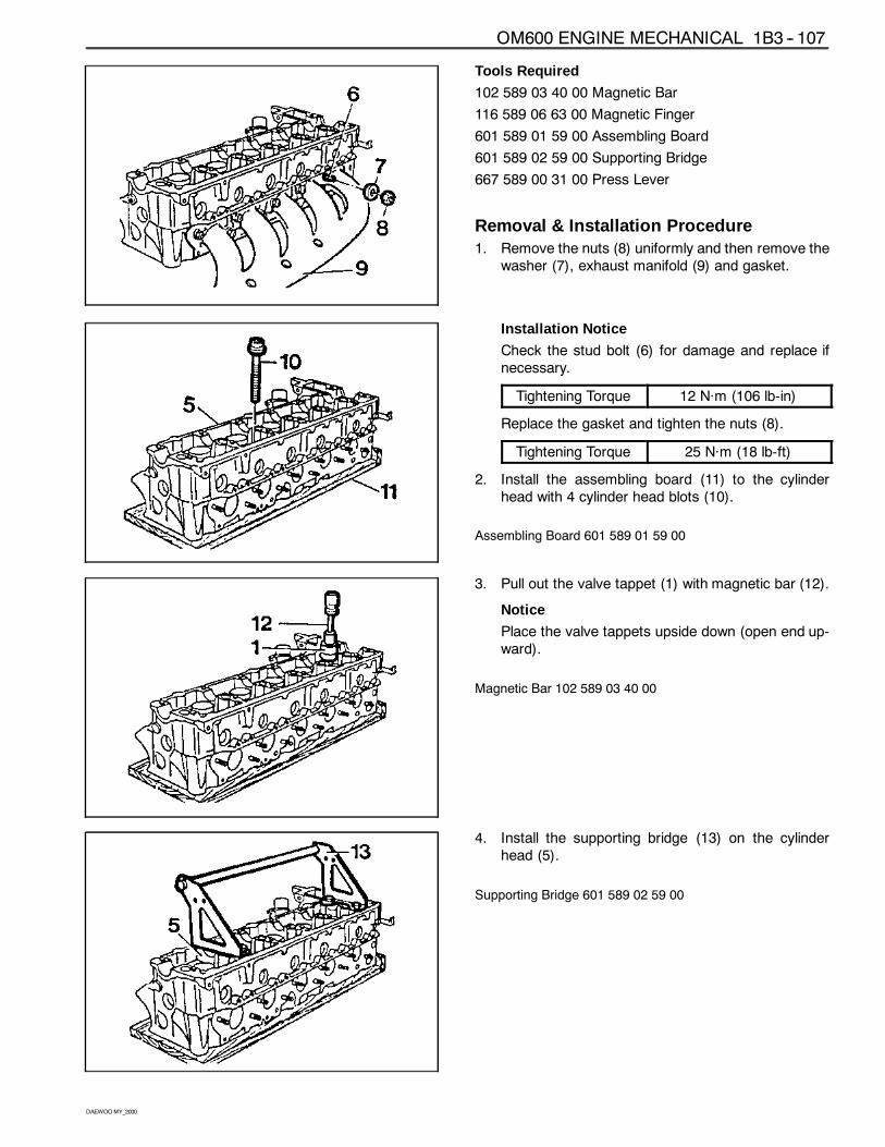
Removal & Installation Procedure1. Remove the nuts (8) uniformly and then remove the
washer (7), exhaust manifold (9) and gasket.
Installation Notice
Check the stud bolt (6) for damage and replace ifnecessary.
Tightening Torque 12 Năm (106 lb-in)
Replace the gasket and tighten the nuts (8).
Tightening Torque 25 Năm (18 lb-ft)
2. Install the assembling board (11) to the cylinderhead with 4 cylinder head blots (10).
Assembling Board 601 589 01 59 00
3. Pull out the valve tappet (1) with magnetic bar (12).
Notice
Place the valve tappets upside down (open end up-ward).
Magnetic Bar 102 589 03 40 00
4. Install the supporting bridge (13) on the cylinderhead (5).
Supporting Bridge 601 589 02 59 00
1B3 -- 108 OM600 ENGINE MECHANICAL
DAEWOOMY_2000
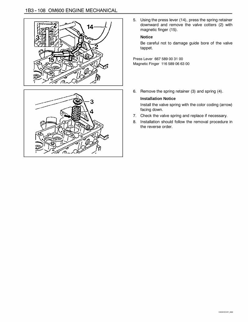
5. Using the press lever (14), press the spring retainerdownward and remove the valve cotters (2) withmagnetic finger (15).
Notice
Be careful not to damage guide bore of the valvetappet.
Press Lever 667 589 00 31 00
Magnetic Finger 116 589 06 63 00
6. Remove the spring retainer (3) and spring (4).
Installation Notice
Install the valve spring with the color coding (arrow)facing down.
7. Check the valve spring and replace if necessary.
8. Installation should follow the removal procedure inthe reverse order.
OM600 ENGINE MECHANICAL 1B3 -- 109
DAEWOOMY_2000
VALVE SPRINGS (CYLINDER HEAD INSTALLED)Preceding Work : Removal of camshaft
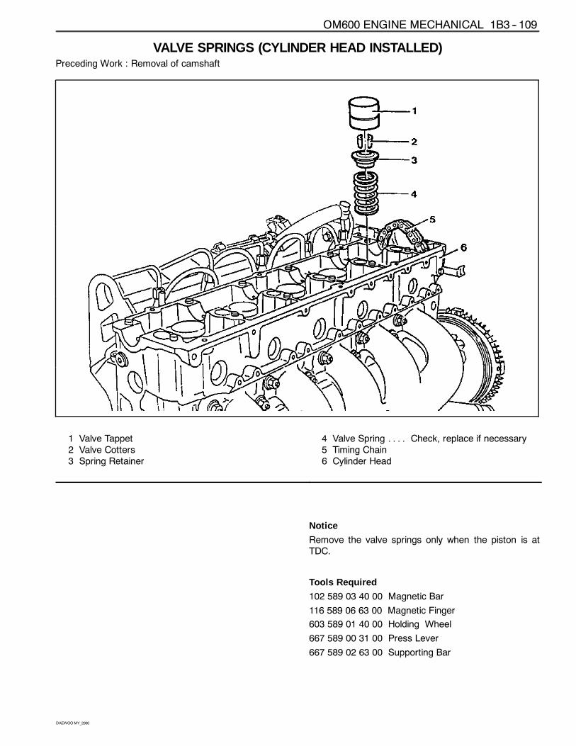
1 Valve Tappet2 Valve Cotters3 Spring Retainer
4 Valve Spring Check, replace if necessary. . . .5 Timing Chain6 Cylinder Head
Notice
Remove the valve springs only when the piston is atTDC.
Tools Required
102 589 03 40 00 Magnetic Bar
116 589 06 63 00 Magnetic Finger
603 589 01 40 00 Holding Wheel
667 589 00 31 00 Press Lever
667 589 02 63 00 Supporting Bar
1B3 -- 110 OM600 ENGINE MECHANICAL
DAEWOOMY_2000
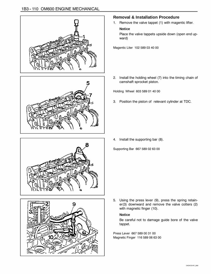
Removal & Installation Procedure1. Remove the valve tappet (1) with magentic lifter.
Notice
Place the valve tappets upside down (open end up-ward)
Magentic Liter 102 589 03 40 00
2. Install the holding wheel (7) into the timing chain ofcamshaft sprocket piston.
Holding Wheel 603 589 01 40 00
3. Position the piston of relevant cylinder at TDC.
4. Install the supporting bar (8).
Supporting Bar 667 589 02 63 00
5. Using the press lever (9), press the spring retain-er(3) downward and remove the valve cotters (2)with magnetic finger (10).
Notice
Be careful not to damage guide bore of the valvetappet.
Press Lever 667 589 00 31 00
Magnetic Finger 116 589 06 63 00
OM600 ENGINE MECHANICAL 1B3 -- 111
DAEWOOMY_2000
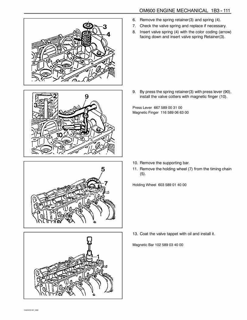
6. Remove the spring retainer(3) and spring (4).
7. Check the valve spring and replace if necessary.
8. Insert valve spring (4) with the color coding (arrow)facing down and insert valve spring Retainer(3).
9. By press the spring retainer(3) with press lever (90),install the valve cotters with magnetic finger (10).
Press Lever 667 589 00 31 00
Magnetic Finger 116 589 06 63 00
10. Remove the supporting bar.
11. Remove the holding wheel (7) from the timing chain(5).
Holding Wheel 603 589 01 40 00
13. Coat the valve tappet with oil and install it.
Magnetic Bar 102 589 03 40 00
1B3 -- 112 OM600 ENGINE MECHANICAL
DAEWOOMY_2000
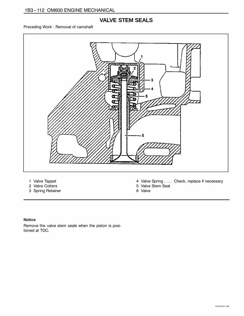
VALVE STEM SEALSPreceding Work : Removal of camshaft
1 Valve Tappet2 Valve Cotters3 Spring Retainer
4 Valve Spring Check, replace if necessary. . . .5 Valve Stem Seal6 Valve
Notice
Remove the valve stem seals when the piston is posi-tioned at TDC.
OM600 ENGINE MECHANICAL 1B3 -- 113
DAEWOOMY_2000
Tools Required
667 589 00 31 00 Press Lever
104 589 00 37 00 Pliers
102 589 03 40 00 Magnetic Lifter
603 589 01 40 00 Holding Wheel
601 589 02 43 00 Drift
116 589 06 63 00 Magnetic Finger
667 589 02 63 00 Supporting Bar
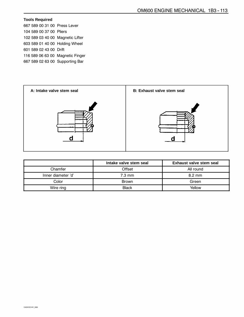
A: Intake valve stem seal B: Exhaust valve stem seal
������������������������������������������������������������������������������������������������������������������������������������������������������������������������������������������������������������������������������������������������������������������������
������������������������������������������������������������������������������������������������������������������������������������������������������������������������������������������������������������������������������������������������������������������������Intake valve stem seal
���������������������������������������������������������������������������������������������������������������������������������������������������������������������������������������������������������������������������������������������������������������Exhaust valve stem seal
Chamfer Offset All round
Inner diameter ’d’ 7.3 mm 8.2 mm
Color Brown Green
Wire ring Black Yellow
1B3 -- 114 OM600 ENGINE MECHANICAL
DAEWOOMY_2000
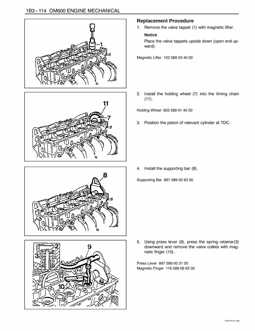
Replacement Procedure1. Remove the valve tappet (1) with magnetic lifter.
Notice
Place the valve tappets upside down (open end up-ward).
Magnetic Lifter 102 589 03 40 00
2. Install the holding wheel (7) into the timing chain(11).
Holding Wheel 603 589 01 40 00
3. Position the piston of relevant cylinder at TDC.
4. Install the supporting bar (8).
Supporting Bar 667 589 02 63 00
5. Using press lever (9), press the spring retainer(3)downward and remove the valve collets with mag-netic finger (10).
Press Lever 667 589 00 31 00
Magnetic Finger 116 589 06 63 00
OM600 ENGINE MECHANICAL 1B3 -- 115
DAEWOOMY_2000
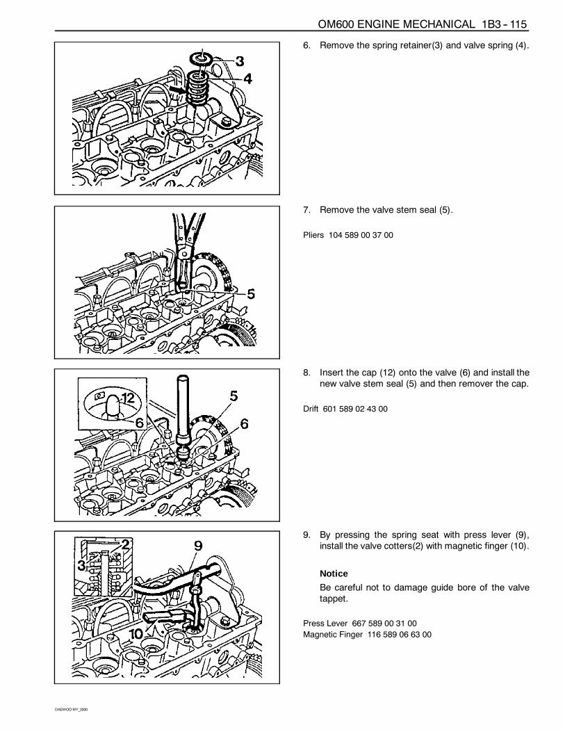
6. Remove the spring retainer(3) and valve spring (4).
7. Remove the valve stem seal (5).
Pliers 104 589 00 37 00
8. Insert the cap (12) onto the valve (6) and install thenew valve stem seal (5) and then remover the cap.
Drift 601 589 02 43 00
9. By pressing the spring seat with press lever (9),install the valve cotters(2) with magnetic finger (10).
Notice
Be careful not to damage guide bore of the valvetappet.
Press Lever 667 589 00 31 00
Magnetic Finger 116 589 06 63 00
1B3 -- 116 OM600 ENGINE MECHANICAL
DAEWOOMY_2000
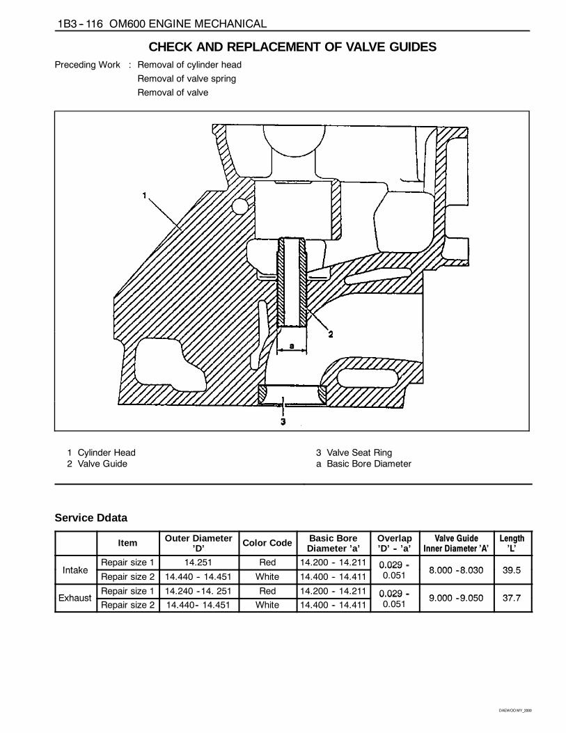
CHECK AND REPLACEMENT OF VALVE GUIDESPreceding Work : Removal of cylinder head
Removal of valve spring
Removal of valve
1 Cylinder Head2 Valve Guide
3 Valve Seat Ringa Basic Bore Diameter
Service Ddata������������������������������������������������������������������������
���������������������������������������������������������������������������������������������������������
Item
���������������������������������������������������������������������������������������������������������������������������������������
Outer Diameter’D’
���������������������������������������������������������������������������������������������������
Color Code
���������������������������������������������������������������������������������������������������������������������������
Basic BoreDiameter ’a’
������������������������������������������������������������������������������������
Overlap’D’ -- ’a’
������������������������������������������������������������������������������������������������������������������������������
Valve GuideInner Diameter ’A’
������������������������������������������������������������������Length’L’
IntakeRepair size 1 14.251 Red 14.200 -- 14.211 0.029 --
8 000 8 030 39 5IntakeRepair size 2 14.440 -- 14.451 White 14.400 -- 14.411
0.029 --0.051
8.000 --8.030 39.5
ExhaustRepair size 1 14.240 --14. 251 Red 14.200 -- 14.211 0.029 --
9 000 9 050 37 7ExhaustRepair size 2 14.440-- 14.451 White 14.400 -- 14.411
0.029 --0.051
9.000 --9.050 37.7
OM600 ENGINE MECHANICAL 1B3 -- 117
DAEWOOMY_2000
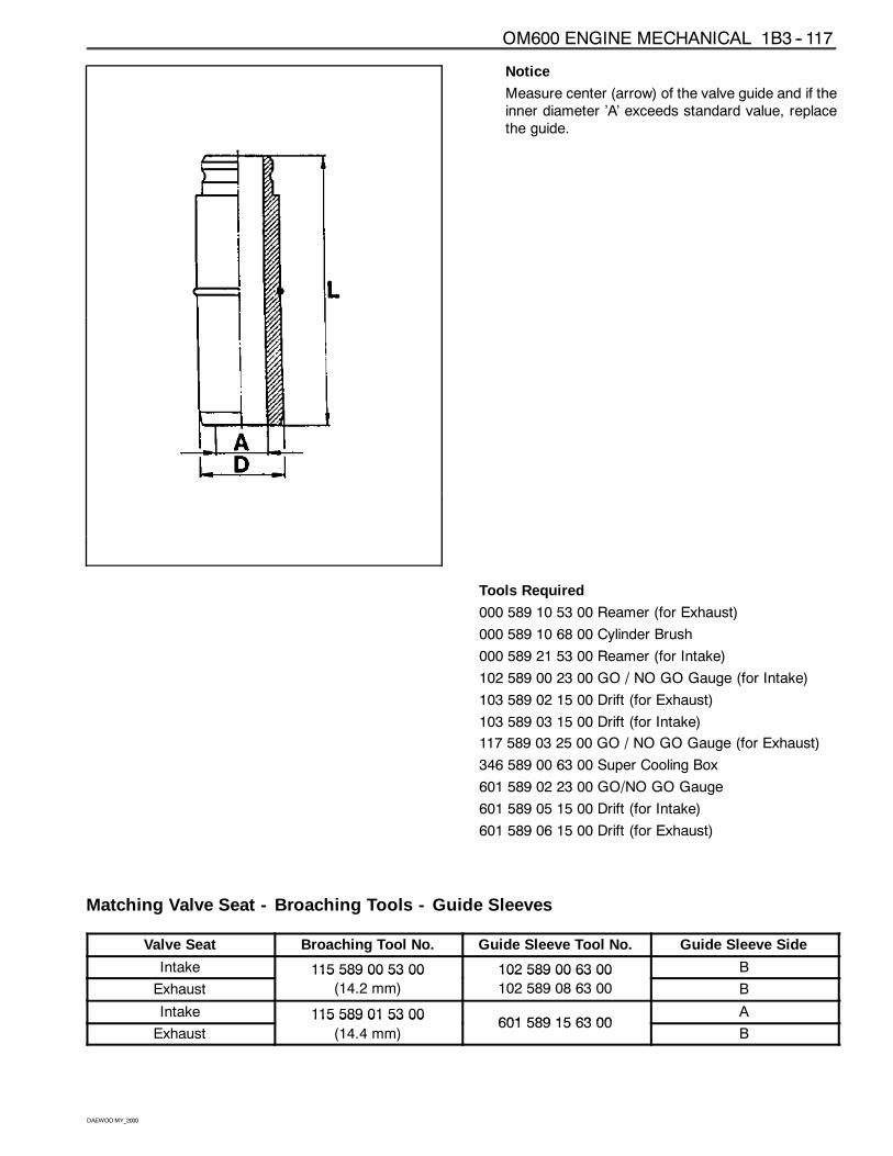
Notice
Measure center (arrow) of the valve guide and if theinner diameter ’A’ exceeds standard value, replacethe guide.
Tools Required
000 589 10 53 00 Reamer (for Exhaust)
000 589 10 68 00 Cylinder Brush
000 589 21 53 00 Reamer (for Intake)
102 589 00 23 00 GO / NO GO Gauge (for Intake)
103 589 02 15 00 Drift (for Exhaust)
103 589 03 15 00 Drift (for Intake)
117 589 03 25 00 GO / NO GO Gauge (for Exhaust)
346 589 00 63 00 Super Cooling Box
601 589 02 23 00 GO/NO GO Gauge
601 589 05 15 00 Drift (for Intake)
601 589 06 15 00 Drift (for Exhaust)
Matching Valve Seat - Broaching Tools - Guide Sleeves������������������������������������������������������������������������������������������������������������������������������������������������������������������������������������������������������Valve Seat
������������������������������������������������������������������������������������������������������������������������������������������������������������������������������������������������������Broaching Tool No.
���������������������������������������������������������������������������������������������������������������������������������������������������������������������������������������������������Guide Sleeve Tool No.
������������������������������������������������������������������������������������������������������������������������������������������������������������������������������������������������������Guide Sleeve Side
Intake 115 589 00 53 00 102 589 00 63 00 B
Exhaust
115 589 00 53 00
(14.2 mm)
102 589 00 63 00
102 589 08 63 00 B
Intake 115 589 01 53 00601 589 15 63 00
A
Exhaust
115 589 01 53 00
(14.4 mm)601 589 15 63 00
B
1B3 -- 118 OM600 ENGINE MECHANICAL
DAEWOOMY_2000
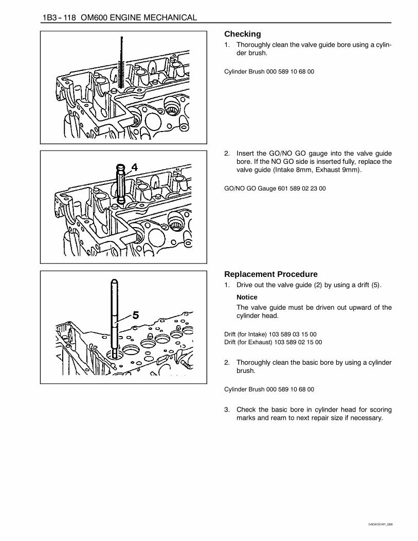
Checking1. Thoroughly clean the valve guide bore using a cylin-
der brush.
Cylinder Brush 000 589 10 68 00
2. Insert the GO/NO GO gauge into the valve guidebore. If the NO GO side is inserted fully, replace thevalve guide (Intake 8mm, Exhaust 9mm).
GO/NO GO Gauge 601 589 02 23 00
Replacement Procedure1. Drive out the valve guide (2) by using a drift (5).
Notice
The valve guide must be driven out upward of thecylinder head.
Drift (for Intake) 103 589 03 15 00
Drift (for Exhaust) 103 589 02 15 00
2. Thoroughly clean the basic bore by using a cylinderbrush.
Cylinder Brush 000 589 10 68 00
3. Check the basic bore in cylinder head for scoringmarks and ream to next repair size if necessary.
OM600 ENGINE MECHANICAL 1B3 -- 119
DAEWOOMY_2000
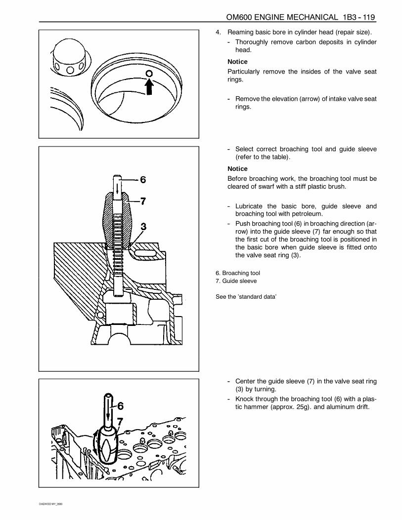
4. Reaming basic bore in cylinder head (repair size).
-- Thoroughly remove carbon deposits in cylinderhead.
Notice
Particularly remove the insides of the valve seatrings.
-- Remove the elevation (arrow) of intake valve seatrings.
-- Select correct broaching tool and guide sleeve(refer to the table).
Notice
Before broaching work, the broaching tool must becleared of swarf with a stiff plastic brush.
-- Lubricate the basic bore, guide sleeve andbroaching tool with petroleum.
-- Push broaching tool (6) in broaching direction (ar-row) into the guide sleeve (7) far enough so thatthe first cut of the broaching tool is positioned inthe basic bore when guide sleeve is fitted ontothe valve seat ring (3).
6. Broaching tool
7. Guide sleeve
See the ’standard data’
-- Center the guide sleeve (7) in the valve seat ring(3) by turning.
-- Knock through the broaching tool (6) with a plas-tic hammer (approx. 25g). and aluminum drift.
1B3 -- 120 OM600 ENGINE MECHANICAL
DAEWOOMY_2000
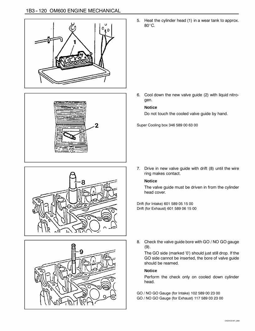
5. Heat the cylinder head (1) in a wear tank to approx.80_C.
6. Cool down the new valve guide (2) with liquid nitro-gen.
Notice
Do not touch the cooled valve guide by hand.
Super Cooling box 346 589 00 63 00
7. Drive in new valve guide with drift (8) until the wirering makes contact.
Notice
The valve guide must be driven in from the cylinderhead cover.
Drift (for Intake) 601 589 05 15 00
Drift (for Exhaust) 601 589 06 15 00
8. Check the valve guide bore with GO / NO GO gauge(9).
The GO side (marked ’0’) should just still drop. If theGO side cannot be inserted, the bore of valve guideshould be reamed.
Notice
Perform the check only on cooled down cylinderhead.
GO / NO GO Gauge (for Intake) 102 589 00 23 00
GO / NO GO Gauge (for Exhaust) 117 589 03 23 00
OM600 ENGINE MECHANICAL 1B3 -- 121
DAEWOOMY_2000
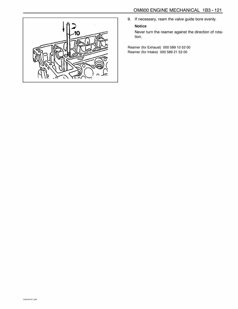
9. If necessary, ream the valve guide bore evenly.
Notice
Never turn the reamer against the direction of rota-tion.
Reamer (for Exhaust) 000 589 10 53 00
Reamer (for Intake) 000 589 21 53 00
1B3 -- 122 OM600 ENGINE MECHANICAL
DAEWOOMY_2000
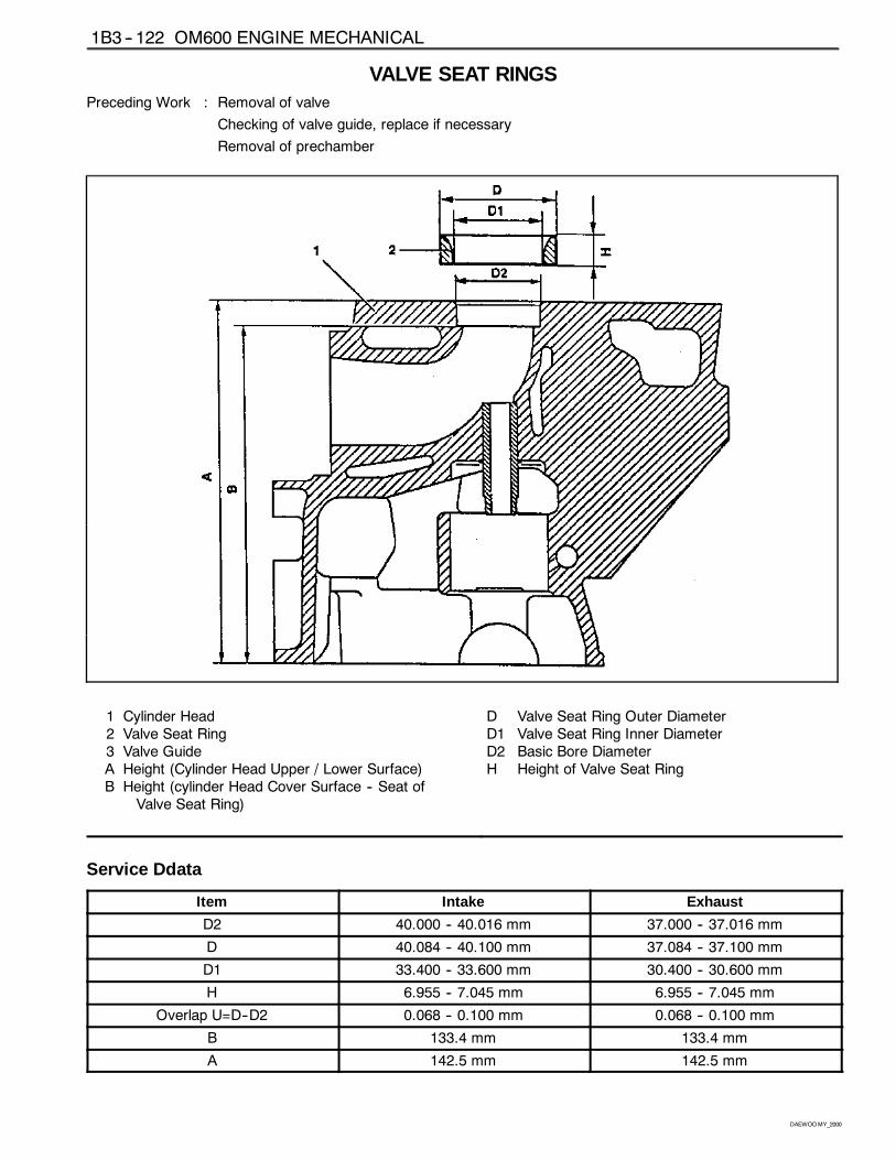
VALVE SEAT RINGSPreceding Work : Removal of valve
Checking of valve guide, replace if necessary
Removal of prechamber
1 Cylinder Head2 Valve Seat Ring3 Valve GuideA Height (Cylinder Head Upper / Lower Surface)B Height (cylinder Head Cover Surface -- Seat of
Valve Seat Ring)
D Valve Seat Ring Outer DiameterD1 Valve Seat Ring Inner DiameterD2 Basic Bore DiameterH Height of Valve Seat Ring
Service Ddata���������������������������������������������������������������������������������������������������������������������������������������������������������������������������������������������������������������������������������������������������������������������Item
���������������������������������������������������������������������������������������������������������������������������������������������������������������������������������������������������������������������������������������������������������������������Intake
���������������������������������������������������������������������������������������������������������������������������������������������������������������������������������������������������������������������������������������������������������������������Exhaust
D2 40.000 -- 40.016 mm 37.000 -- 37.016 mm
D 40.084 -- 40.100 mm 37.084 -- 37.100 mm
D1 33.400 -- 33.600 mm 30.400 -- 30.600 mm
H 6.955 -- 7.045 mm 6.955 -- 7.045 mm
Overlap U=D--D2 0.068 -- 0.100 mm 0.068 -- 0.100 mm
B 133.4 mm 133.4 mm
A 142.5 mm 142.5 mm
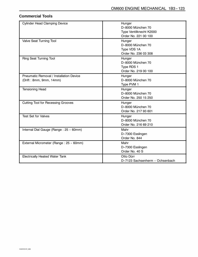
OM600 ENGINE MECHANICAL 1B3 -- 123
DAEWOOMY_2000
Commercial Tools
Cylinder Head Clamping Device Hunger
D--8000 München 70
Type Ventilknecht K2000
Order No. 221 00 100
Valve Seat Turning Tool Hunger
D--8000 München 70
Type VDS 1A
Order No. 236 03 308
Ring Seat Turning Tool Hunger
D--8000 München 70
Type RDS 1
Order No. 219 00 100
Pneumatic Removal / Installation Device
(Drift : 8mm, 9mm, 14mm)
Hunger
D--8000 München 70
Type PVM 1
Tensioning Head Hunger
D--8000 München 70
Order No. 250 15 250
Cutting Tool for Recessing Grooves Hunger
D--8000 München 70
Order No. 217 93 601
Test Set for Valves Hunger
D--8000 München 70
Order No. 216 69 210
Internal Dial Gauge (Range : 25 -- 60mm) Mahr
D--7300 Esslingen
Order No. 844
External Micrometer (Range : 25 -- 60mm) Mahr
D--7300 Esslingen
Order No. 40 S
Electrically Heated Water Tank Otto Dürr
D--7123 Sachsenherm -- Ochsenbach
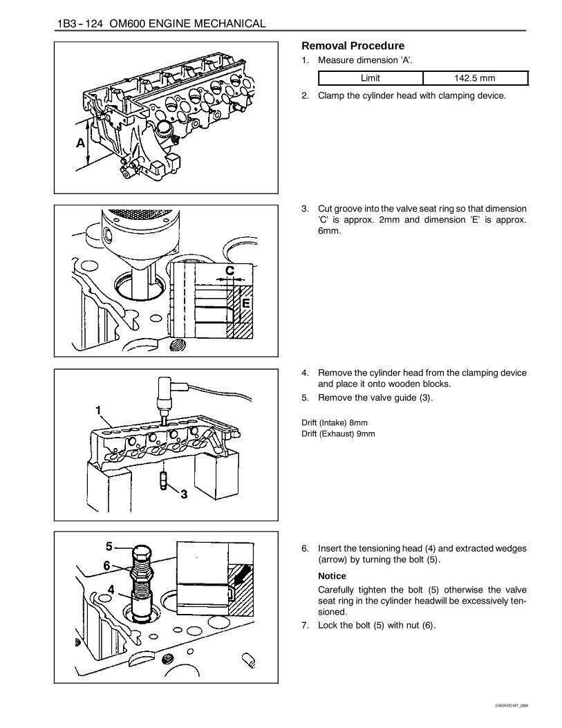
1B3 -- 124 OM600 ENGINE MECHANICAL
DAEWOOMY_2000
Removal Procedure1. Measure dimension ’A’.
Limit 142.5 mm
2. Clamp the cylinder head with clamping device.
3. Cut groove into the valve seat ring so that dimension’C’ is approx. 2mm and dimension ’E’ is approx.6mm.
4. Remove the cylinder head from the clamping deviceand place it onto wooden blocks.
5. Remove the valve guide (3).
Drift (Intake) 8mm
Drift (Exhaust) 9mm
6. Insert the tensioning head (4) and extracted wedges(arrow) by turning the bolt (5).
Notice
Carefully tighten the bolt (5) otherwise the valveseat ring in the cylinder headwill be excessively ten-sioned.
7. Lock the bolt (5) with nut (6).
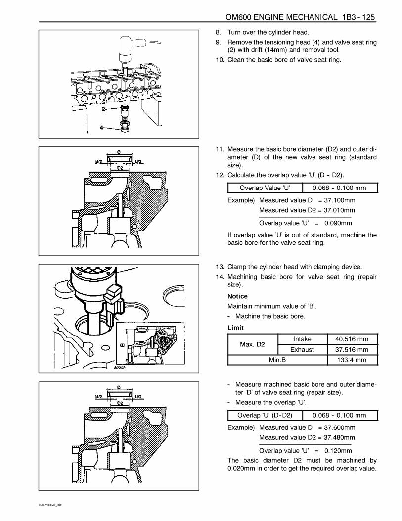
OM600 ENGINE MECHANICAL 1B3 -- 125
DAEWOOMY_2000
8. Turn over the cylinder head.
9. Remove the tensioning head (4) and valve seat ring(2) with drift (14mm) and removal tool.
10. Clean the basic bore of valve seat ring.
11. Measure the basic bore diameter (D2) and outer di-ameter (D) of the new valve seat ring (standardsize).
12. Calculate the overlap value ’U’ (D -- D2).
Overlap Value ’U’ 0.068 -- 0.100 mm
Example) Measured value D = 37.100mm
Measured value D2 = 37.010mm——————————————Overlap value ’U’ = 0.090mm
If overlap value ’U’ is out of standard, machine thebasic bore for the valve seat ring.
13. Clamp the cylinder head with clamping device.
14. Machining basic bore for valve seat ring (repairsize).
Notice
Maintain minimum value of ’B’.
-- Machine the basic bore.
Limit
Max D2Intake 40.516 mm
Max. D2Exhaust 37.516 mm
Min.B 133.4 mm
-- Measure machined basic bore and outer diame-ter ’D’ of valve seat ring (repair size).
-- Measure the overlap ’U’.
Overlap ’U’ (D--D2) 0.068 -- 0.100 mm
Example) Measured value D = 37.600mm
Measured value D2 = 37.480mm——————————————Overlap value ’U’ = 0.120mm
The basic diameter D2 must be machined by0.020mm in order to get the required overlap value.
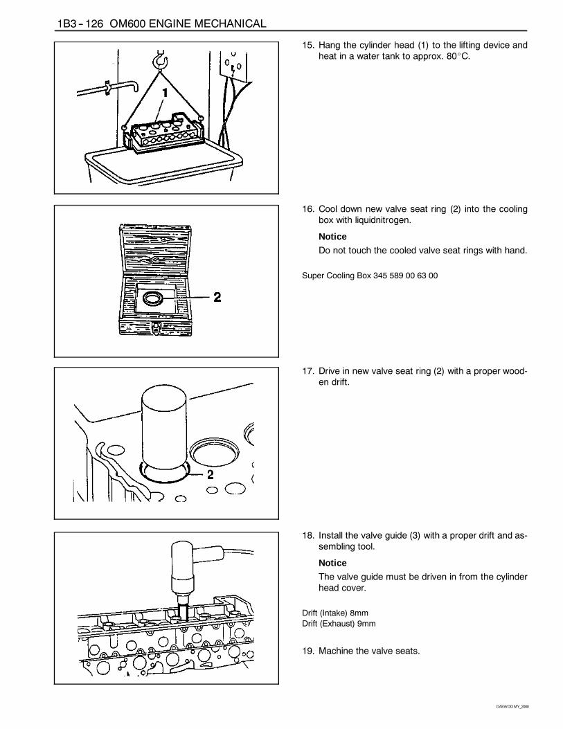
1B3 -- 126 OM600 ENGINE MECHANICAL
DAEWOOMY_2000
15. Hang the cylinder head (1) to the lifting device andheat in a water tank to approx. 80_C.
16. Cool down new valve seat ring (2) into the coolingbox with liquidnitrogen.
Notice
Do not touch the cooled valve seat rings with hand.
Super Cooling Box 345 589 00 63 00
17. Drive in new valve seat ring (2) with a proper wood-en drift.
18. Install the valve guide (3) with a proper drift and as-sembling tool.
Notice
The valve guide must be driven in from the cylinderhead cover.
Drift (Intake) 8mm
Drift (Exhaust) 9mm
19. Machine the valve seats.
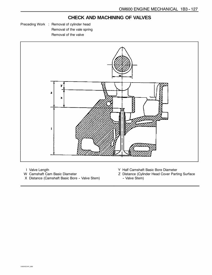
OM600 ENGINE MECHANICAL 1B3 -- 127
DAEWOOMY_2000
CHECK AND MACHINING OF VALVESPreceding Work : Removal of cylinder head
Removal of the vale spring
Removal of the valve
I Valve LengthW Camshaft Cam Basic DiameterX Distance (Camshaft Basic Bore -- Valve Stem)
Y Half Camshaft Basic Bore DiameterZ Distance (Cylinder Head Cover Parting Surface
-- Valve Stem)
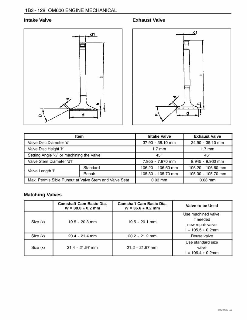
1B3 -- 128 OM600 ENGINE MECHANICAL
DAEWOOMY_2000
Intake Valve Exhaust Valve
���������������������������������������������������������������������������������������������������������������������������������������������������������������������������������������������������������������������������������������������������������������������������������������������������������������������������������������������������������������������������������������������������������������������������������Item
���������������������������������������������������������������������������������������������������������������������������������������������������������������������������������������Intake Valve
���������������������������������������������������������������������������������������������������������������������������������������������������������������������������������������Exhaust Valve
Valve Disc Diameter ’d’ 37.90 -- 38.10 mm 34.90 -- 35.10 mm
Valve Disc Height ’h’ 1.7 mm 1.7 mm
Setting Angle “α” or machining the Valve 45_ 45_
Valve Stem Diameter ’d1’ 7.955 -- 7.970 mm 9.945 -- 9.960 mm
Valve Length ’I’Standard 106.20 -- 106.60 mm 106.20 -- 106.60 mm
Valve Length ’I’Repair 105.30 -- 105.70 mm 105.30 -- 105.70 mm
Max. Permis Sible Runout at Valve Stem and Valve Seat 0.03 mm 0.03 mm
Matching Valves���������������������������������������������������������������������������������������������������������������
���������������������������������������������������������������������������������������������������������������������������������������������������������������������������������������������������������������������������������
Camshaft Cam Basic Dia.W = 38.0 ± 0.2 mm
���������������������������������������������������������������������������������������������������������������������������������������������������������������������������������������������������������������������������������
Camshaft Cam Basic Dia.W = 36.6 ± 0.2 mm
���������������������������������������������������������������������������������������������������������������������������������������������������������������������������������������������������������������������������������Valve to be Used
Size (x) 19.5 -- 20.3 mm 19.5 -- 20.1 mm
Use machined valve,
if needed
new repair valve
I = 105.5 ± 0.2mm
Size (x) 20.4 -- 21.4 mm 20.2 -- 21.2 mm Reuse valve
Size (x) 21.4 -- 21.97 mm 21.2 -- 21.97 mm
Use standard size
valve
I = 106.4 ± 0.2mm
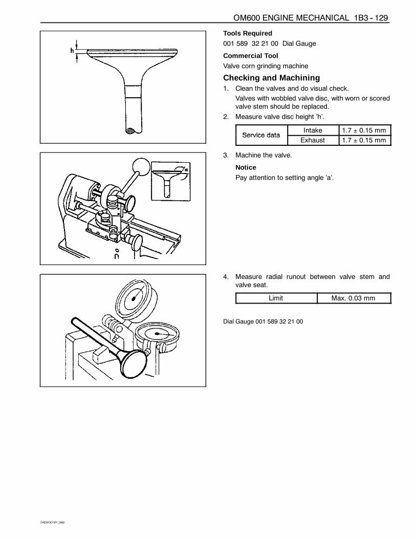
OM600 ENGINE MECHANICAL 1B3 -- 129
DAEWOOMY_2000
Tools Required
001 589 32 21 00 Dial Gauge
Commercial Tool
Valve corn grinding machine
Checking and Machining1. Clean the valves and do visual check.
Valves with wobbled valve disc, with worn or scoredvalve stem should be replaced.
2. Measure valve disc height ’h’.
Service dataIntake 1.7 ± 0.15 mm
Service dataExhaust 1.7 ± 0.15 mm
3. Machine the valve.
Notice
Pay attention to setting angle ’a’.
4. Measure radial runout between valve stem andvalve seat.
Limit Max. 0.03 mm
Dial Gauge 001 589 32 21 00
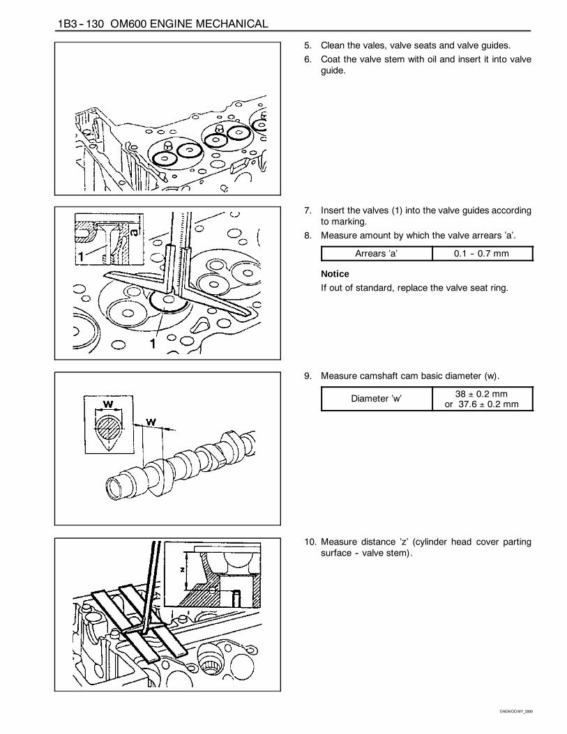
1B3 -- 130 OM600 ENGINE MECHANICAL
DAEWOOMY_2000
5. Clean the vales, valve seats and valve guides.
6. Coat the valve stem with oil and insert it into valveguide.
7. Insert the valves (1) into the valve guides accordingto marking.
8. Measure amount by which the valve arrears ’a’.
Arrears ’a’ 0.1 -- 0.7 mm
Notice
If out of standard, replace the valve seat ring.
9. Measure camshaft cam basic diameter (w).
Diameter ’w’38 ± 0.2 mm
or 37.6 ± 0.2 mm
10. Measure distance ’z’ (cylinder head cover partingsurface -- valve stem).
OM600 ENGINE MECHANICAL 1B3 -- 131
DAEWOOMY_2000
11. The distance ’x’ (camshaft basic bore -- valve stem).
’x’ = ’z’ -- ’y’.
Determine the valve to use according to this mea-surement (See ’matching valves’)
Example) Measured value ’w’= 38.2 mm
Measured value ’z’ = 36.5 mm—————————————Value ’y’ = 15.5 mm
’x’ = 36.5 -- 15.5 = 21.0mm
In this case according to ’Matching valves’ table, theinstalled valve may be used.
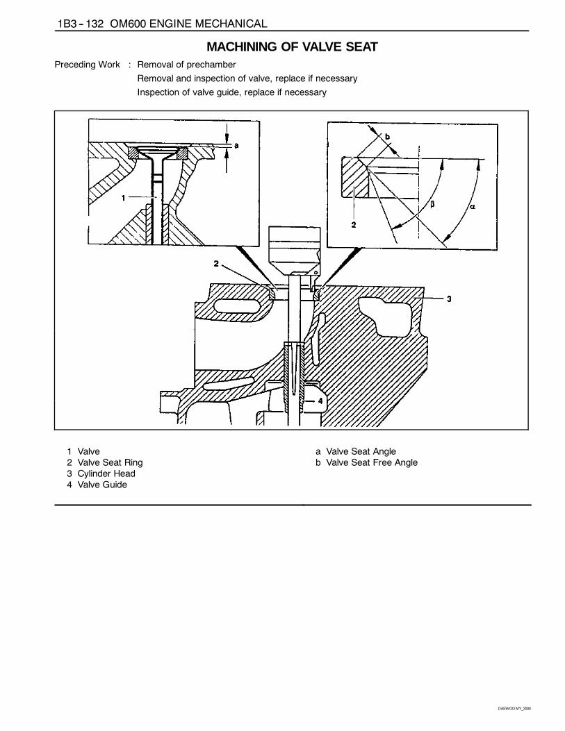
1B3 -- 132 OM600 ENGINE MECHANICAL
DAEWOOMY_2000
MACHINING OF VALVE SEATPreceding Work : Removal of prechamber
Removal and inspection of valve, replace if necessary
Inspection of valve guide, replace if necessary
1 Valve2 Valve Seat Ring3 Cylinder Head4 Valve Guide
a Valve Seat Angleb Valve Seat Free Angle
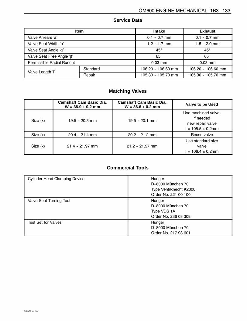
OM600 ENGINE MECHANICAL 1B3 -- 133
DAEWOOMY_2000
Service Data
Item Intake Exhaust
Valve Arrears ’a’ 0.1 -- 0.7 mm 0.1 -- 0.7 mm
Valve Seat Width ’b’ 1.2 -- 1.7 mm 1.5 -- 2.0 mm
Valve Seat Angle ’α’ 45_ 45_
Valve Seat Free Angle ’β’ 65_ 65_
Permissible Radial Runout 0.03 mm 0.03 mm
Valve Length ’I’Standard 106.20 -- 106.60 mm 106.20 -- 106.60 mm
Valve Length ’I’Repair 105.30 -- 105.70 mm 105.30 -- 105.70 mm
Matching Valves
Camshaft Cam Basic Dia.W = 38.0 ± 0.2 mm
Camshaft Cam Basic Dia.W = 36.6 ± 0.2 mm
Valve to be Used
Size (x) 19.5 -- 20.3 mm 19.5 -- 20.1 mm
Use machined valve,
if needed
new repair valve
I = 105.5 ± 0.2mm
Size (x) 20.4 -- 21.4 mm 20.2 -- 21.2 mm Reuse valve
Size (x) 21.4 -- 21.97 mm 21.2 -- 21.97 mm
Use standard size
valve
I = 106.4 ± 0.2mm
Commercial Tools
Cylinder Head Clamping Device Hunger
D--8000 München 70
Type Ventilknecht K2000
Order No. 221 00 100
Valve Seat Turning Tool Hunger
D--8000 München 70
Type VDS 1A
Order No. 236 03 308
Test Set for Valves Hunger
D--8000 München 70
Order No. 217 93 601
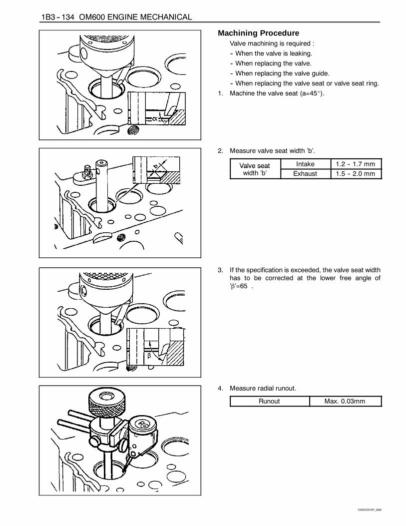
1B3 -- 134 OM600 ENGINE MECHANICAL
DAEWOOMY_2000
Machining ProcedureValve machining is required :
-- When the valve is leaking.
-- When replacing the valve.
-- When replacing the valve guide.
-- When replacing the valve seat or valve seat ring.
1. Machine the valve seat (a=45_).
2. Measure valve seat width ’b’.
Valve seat Intake 1.2 -- 1.7 mmValve seatwidth ’b’ Exhaust 1.5 -- 2.0 mm
3. If the specification is exceeded, the valve seat widthhas to be corrected at the lower free angle of’β’=65�.
4. Measure radial runout.
Runout Max. 0.03mm
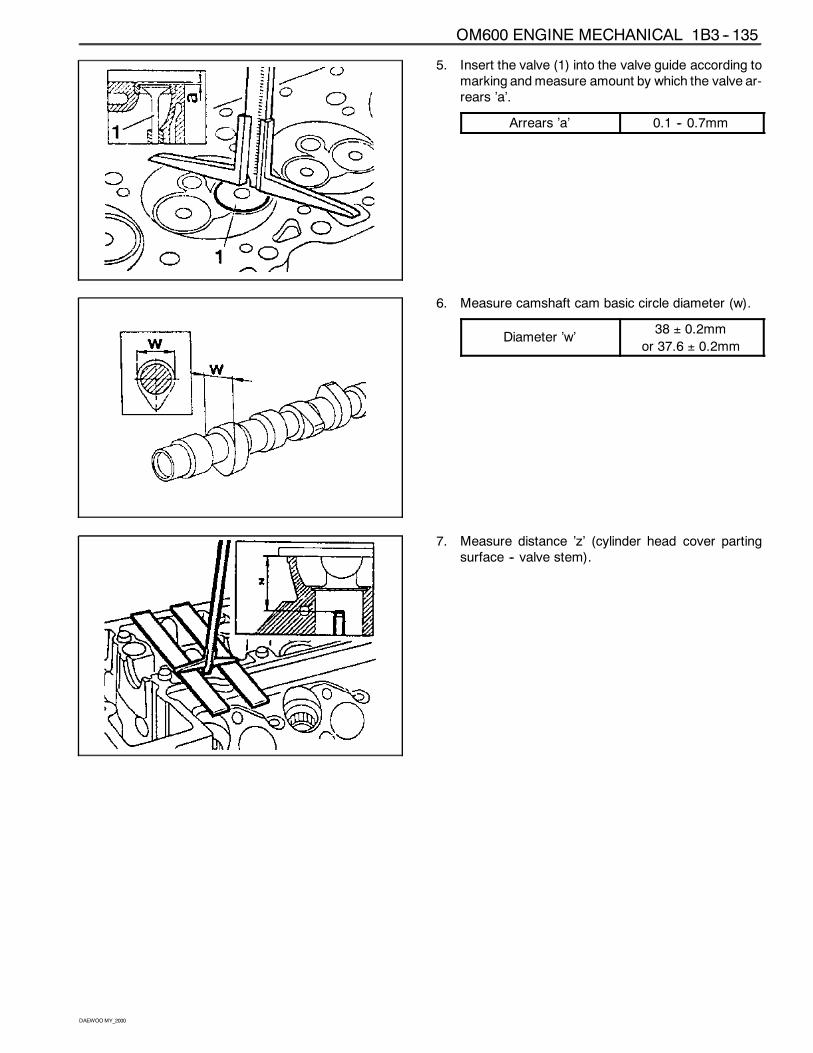
OM600 ENGINE MECHANICAL 1B3 -- 135
DAEWOOMY_2000
5. Insert the valve (1) into the valve guide according tomarking andmeasure amount by which the valve ar-rears ’a’.
Arrears ’a’ 0.1 -- 0.7mm
6. Measure camshaft cam basic circle diameter (w).
Diameter ’w’38 ± 0.2mm
or 37.6 ± 0.2mm
7. Measure distance ’z’ (cylinder head cover partingsurface -- valve stem).
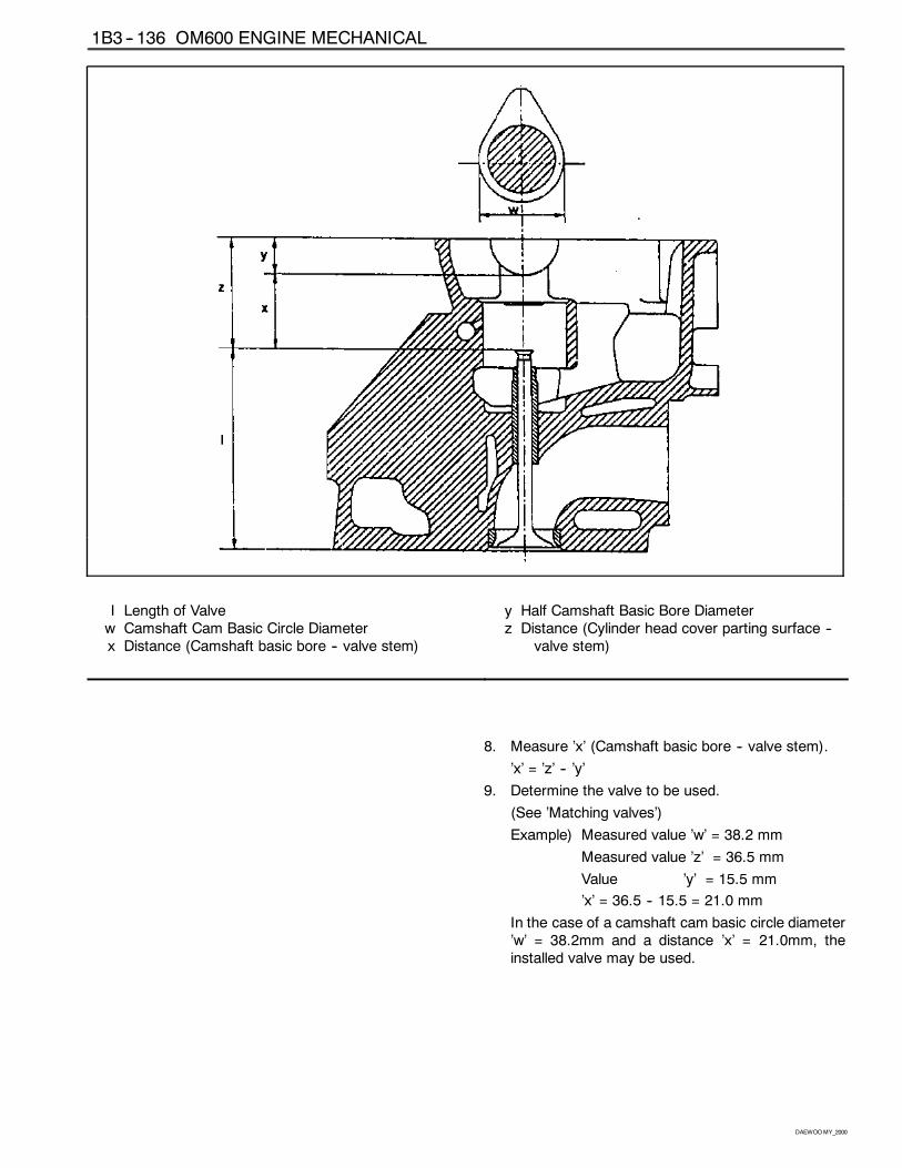
1B3 -- 136 OM600 ENGINE MECHANICAL
DAEWOOMY_2000
I Length of Valvew Camshaft Cam Basic Circle Diameterx Distance (Camshaft basic bore -- valve stem)
y Half Camshaft Basic Bore Diameterz Distance (Cylinder head cover parting surface --
valve stem)
8. Measure ’x’ (Camshaft basic bore -- valve stem).
’x’ = ’z’ -- ’y’
9. Determine the valve to be used.
(See ’Matching valves’)
Example) Measured value ’w’ = 38.2 mm
Measured value ’z’ = 36.5 mm
Value ’y’ = 15.5 mm
’x’ = 36.5 -- 15.5 = 21.0 mm
In the case of a camshaft cam basic circle diameter’w’ = 38.2mm and a distance ’x’ = 21.0mm, theinstalled valve may be used.
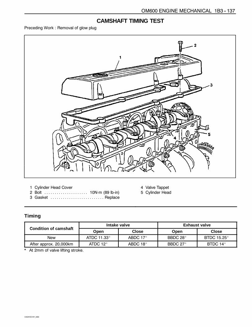
OM600 ENGINE MECHANICAL 1B3 -- 137
DAEWOOMY_2000
CAMSHAFT TIMING TESTPreceding Work : Removal of glow plug
1 Cylinder Head Cover2 Bolt 10Năm (89 lb-in). . . . . . . . . . . . . . . . . . . . .3 Gasket Replace. . . . . . . . . . . . . . . . . . . . . . . . . .
4 Valve Tappet5 Cylinder Head
Timing
C diti f h ftIntake valve Exhaust valve
Condition of camshaftOpen Close Open Close
New ATDC 11.33_ ABDC 17_ BBDC 28_ BTDC 15.25_
After approx. 20,000km ATDC 12_ ABDC 18_ BBDC 27_ BTDC 14_
* At 2mm of valve lifting stroke.
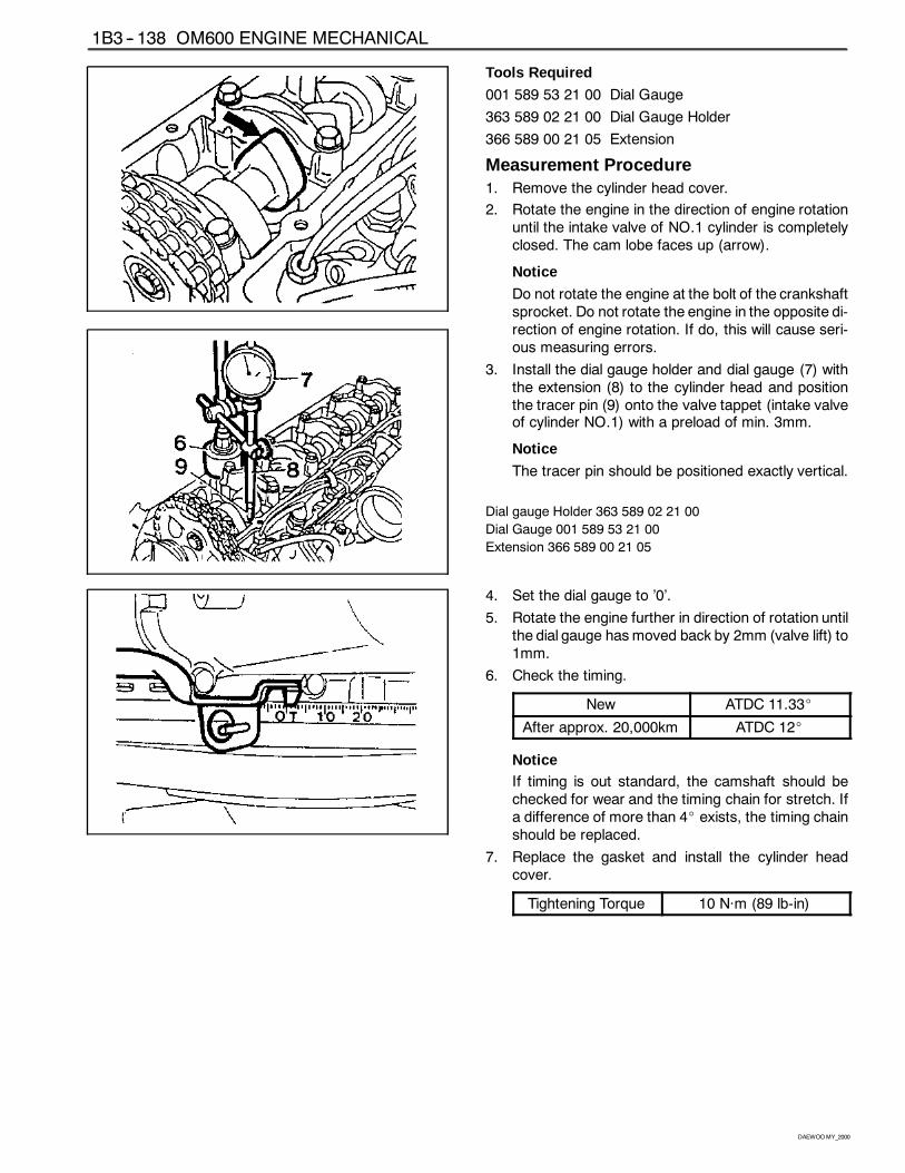
1B3 -- 138 OM600 ENGINE MECHANICAL
DAEWOOMY_2000
Tools Required
001 589 53 21 00 Dial Gauge
363 589 02 21 00 Dial Gauge Holder
366 589 00 21 05 Extension
Measurement Procedure1. Remove the cylinder head cover.
2. Rotate the engine in the direction of engine rotationuntil the intake valve of NO.1 cylinder is completelyclosed. The cam lobe faces up (arrow).
Notice
Do not rotate the engine at the bolt of the crankshaftsprocket. Do not rotate the engine in the opposite di-rection of engine rotation. If do, this will cause seri-ous measuring errors.
3. Install the dial gauge holder and dial gauge (7) withthe extension (8) to the cylinder head and positionthe tracer pin (9) onto the valve tappet (intake valveof cylinder NO.1) with a preload of min. 3mm.
Notice
The tracer pin should be positioned exactly vertical.
Dial gauge Holder 363 589 02 21 00
Dial Gauge 001 589 53 21 00
Extension 366 589 00 21 05
4. Set the dial gauge to ’0’.
5. Rotate the engine further in direction of rotation untilthe dial gauge hasmoved back by 2mm (valve lift) to1mm.
6. Check the timing.
New ATDC 11.33_
After approx. 20,000km ATDC 12_
NoticeIf timing is out standard, the camshaft should bechecked for wear and the timing chain for stretch. Ifa difference of more than 4_ exists, the timing chainshould be replaced.
7. Replace the gasket and install the cylinder headcover.
Tightening Torque 10 Năm (89 lb-in)
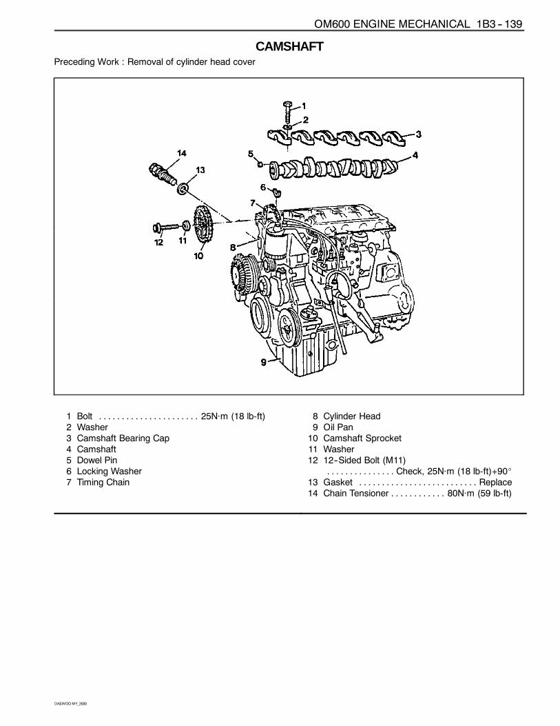
OM600 ENGINE MECHANICAL 1B3 -- 139
DAEWOOMY_2000
CAMSHAFTPreceding Work : Removal of cylinder head cover
1 Bolt 25Năm (18 lb-ft). . . . . . . . . . . . . . . . . . . . . .2 Washer3 Camshaft Bearing Cap4 Camshaft5 Dowel Pin6 Locking Washer7 Timing Chain
8 Cylinder Head9 Oil Pan10 Camshaft Sprocket11 Washer12 12--Sided Bolt (M11)
Check, 25Năm (18 lb-ft)+90_. . . . . . . . . . . . . . .13 Gasket Replace. . . . . . . . . . . . . . . . . . . . . . . . . .14 Chain Tensioner 80Năm (59 lb-ft). . . . . . . . . . . .
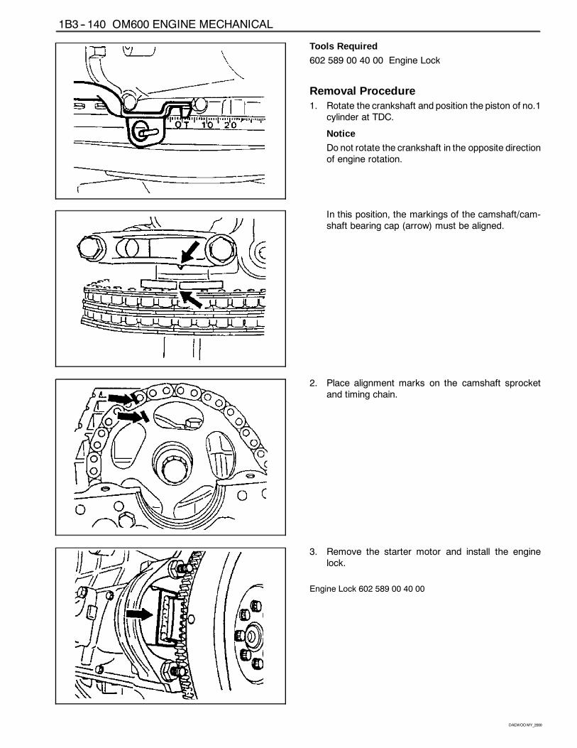
1B3 -- 140 OM600 ENGINE MECHANICAL
DAEWOOMY_2000
Tools Required
602 589 00 40 00 Engine Lock
Removal Procedure1. Rotate the crankshaft and position the piston of no.1
cylinder at TDC.
Notice
Do not rotate the crankshaft in the opposite directionof engine rotation.
In this position, the markings of the camshaft/cam-shaft bearing cap (arrow) must be aligned.
2. Place alignment marks on the camshaft sprocketand timing chain.
3. Remove the starter motor and install the enginelock.
Engine Lock 602 589 00 40 00
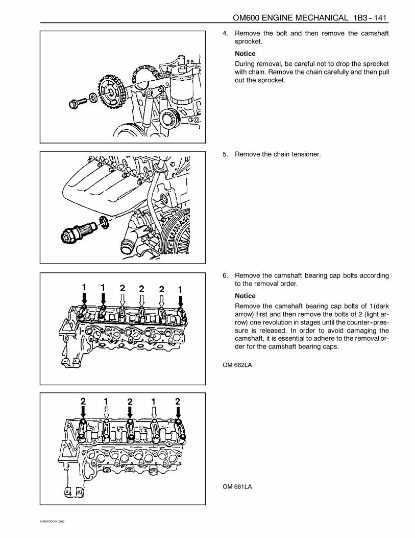
OM600 ENGINE MECHANICAL 1B3 -- 141
DAEWOOMY_2000
4. Remove the bolt and then remove the camshaftsprocket.
Notice
During removal, be careful not to drop the sprocketwith chain. Remove the chain carefully and then pullout the sprocket.
5. Remove the chain tensioner.
6. Remove the camshaft bearing cap bolts accordingto the removal order.
Notice
Remove the camshaft bearing cap bolts of 1(darkarrow) first and then remove the bolts of 2 (light ar-row) one revolution in stages until the counter--pres-sure is released. In order to avoid damaging thecamshaft, it is essential to adhere to the removal or-der for the camshaft bearing caps.
OM 662LA
OM 661LA
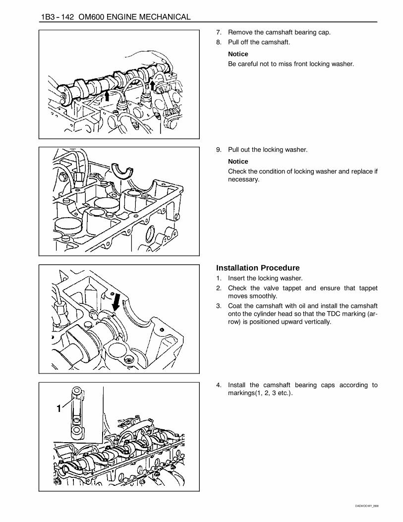
1B3 -- 142 OM600 ENGINE MECHANICAL
DAEWOOMY_2000
7. Remove the camshaft bearing cap.
8. Pull off the camshaft.
Notice
Be careful not to miss front locking washer.
9. Pull out the locking washer.
Notice
Check the condition of locking washer and replace ifnecessary.
Installation Procedure1. Insert the locking washer.
2. Check the valve tappet and ensure that tappetmoves smoothly.
3. Coat the camshaft with oil and install the camshaftonto the cylinder head so that the TDC marking (ar-row) is positioned upward vertically.
4. Install the camshaft bearing caps according tomarkings(1, 2, 3 etc.).
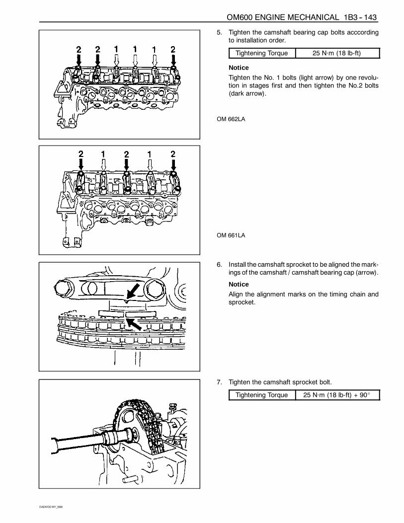
OM600 ENGINE MECHANICAL 1B3 -- 143
DAEWOOMY_2000
5. Tighten the camshaft bearing cap bolts acccordingto installation order.
Tightening Torque 25 Năm (18 lb-ft)
Notice
Tighten the No. 1 bolts (light arrow) by one revolu-tion in stages first and then tighten the No.2 bolts(dark arrow).
OM 662LA
OM 661LA
6. Install the camshaft sprocket to be aligned themark-ings of the camshaft / camshaft bearing cap (arrow).
Notice
Align the alignment marks on the timing chain andsprocket.
7. Tighten the camshaft sprocket bolt.
Tightening Torque 25 Năm (18 lb-ft) + 90_
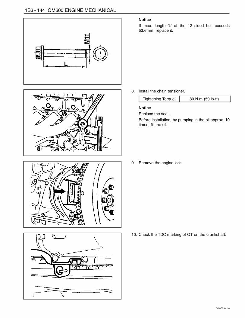
1B3 -- 144 OM600 ENGINE MECHANICAL
DAEWOOMY_2000
Notice
If max. length ’L’ of the 12--sided bolt exceeds53.6mm, replace it.
8. Install the chain tensioner.
Tightening Torque 80 Năm (59 lb-ft)
Notice
Replace the seal.
Before installation, by pumping in the oil approx. 10times, fill the oil.
9. Remove the engine lock.
10. Check the TDC marking of OT on the crankshaft.
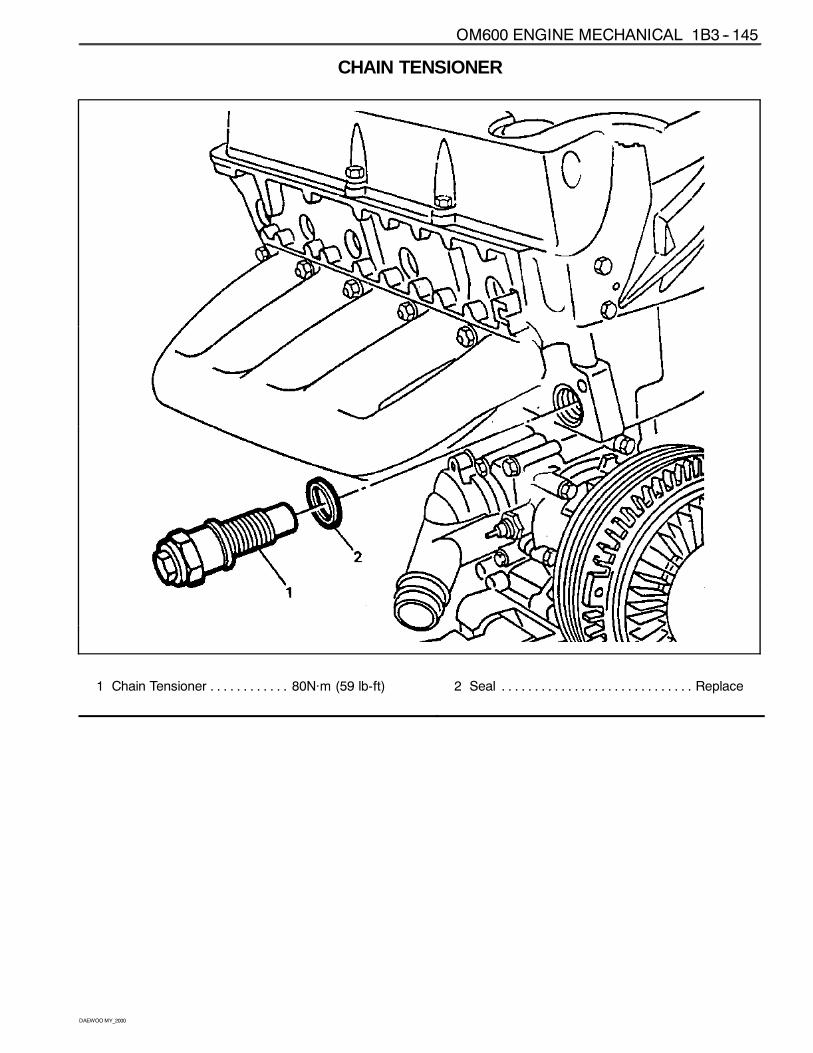
OM600 ENGINE MECHANICAL 1B3 -- 145
DAEWOOMY_2000
CHAIN TENSIONER
1 Chain Tensioner 80Năm (59 lb-ft). . . . . . . . . . . . 2 Seal Replace. . . . . . . . . . . . . . . . . . . . . . . . . . . . .
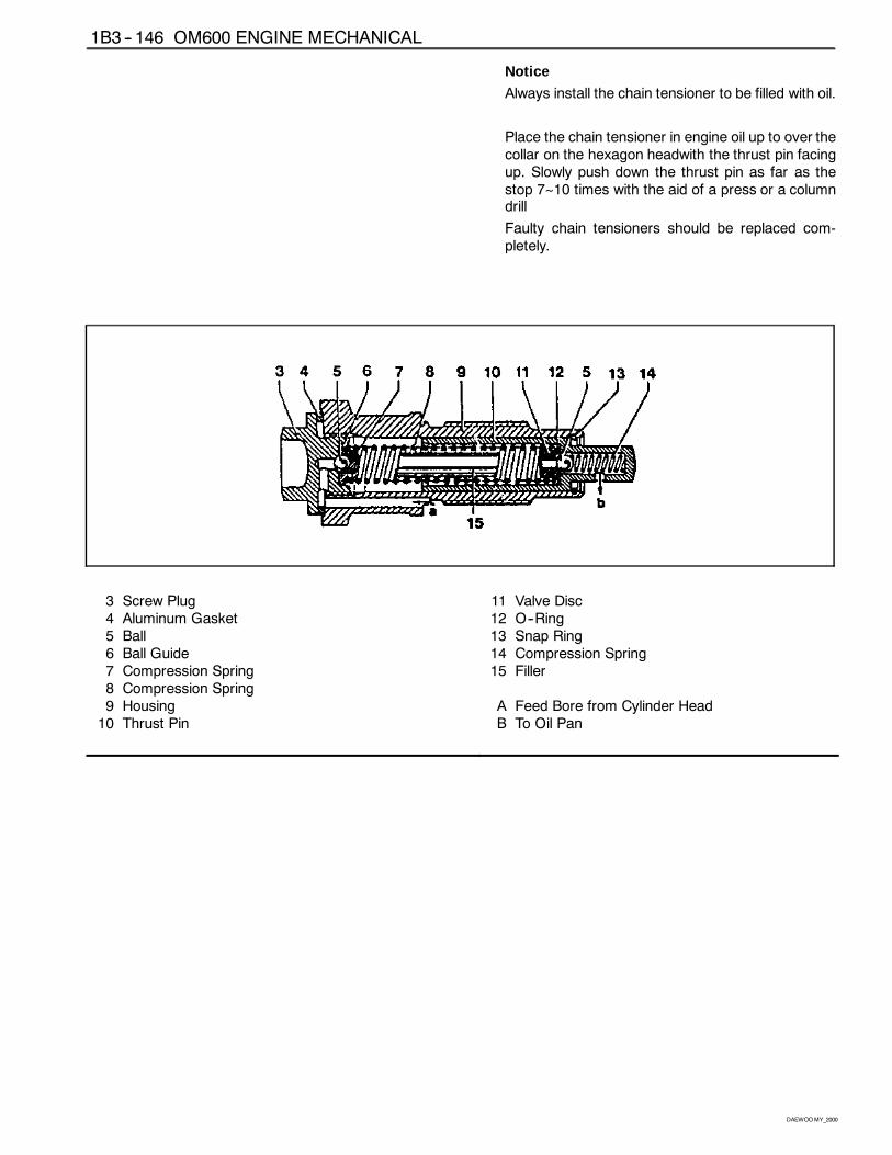
1B3 -- 146 OM600 ENGINE MECHANICAL
DAEWOOMY_2000
Notice
Always install the chain tensioner to be filled with oil.
Place the chain tensioner in engine oil up to over thecollar on the hexagon headwith the thrust pin facingup. Slowly push down the thrust pin as far as thestop 7~10 times with the aid of a press or a columndrill
Faulty chain tensioners should be replaced com-pletely.
3 Screw Plug4 Aluminum Gasket5 Ball6 Ball Guide7 Compression Spring8 Compression Spring9 Housing10 Thrust Pin
11 Valve Disc12 O--Ring13 Snap Ring14 Compression Spring15 Filler
A Feed Bore from Cylinder HeadB To Oil Pan
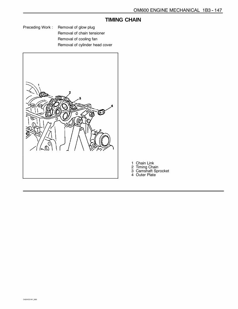
OM600 ENGINE MECHANICAL 1B3 -- 147
DAEWOOMY_2000
TIMING CHAINPreceding Work : Removal of glow plug
Removal of chain tensioner
Removal of cooling fan
Removal of cylinder head cover
1 Chain Link2 Timing Chain3 Camshaft Sprocket4 Outer Plate
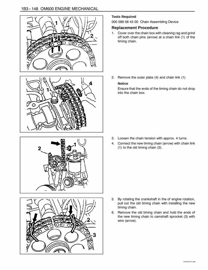
1B3 -- 148 OM600 ENGINE MECHANICAL
DAEWOOMY_2000
Tools Required
000 589 58 43 00 Chain Assembling Device
Replacement Procedure1. Cover over the chain box with cleaning rag and grind
off both chain pins (arrow) at a chain link (1) of thetiming chain.
2. Remove the outer plate (4) and chain link (1).
Notice
Ensure that the ends of the timing chain do not dropinto the chain box.
3. Loosen the chain tension with approx. 4 turns.
4. Connect the new timing chain (arrow) with chain link(1) to the old timing chain (2).
5. By rotating the crankshaft in the of engine rotation,pull out the old timing chain with installing the newtiming chain.
6. Remove the old timing chain and hold the ends ofthe new timing chain to camshaft sprocket (3) withwire (arrow).
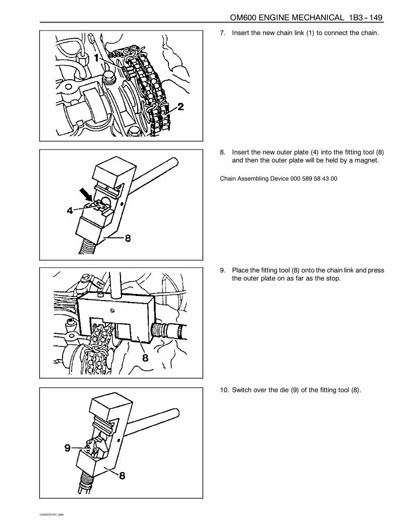
OM600 ENGINE MECHANICAL 1B3 -- 149
DAEWOOMY_2000
7. Insert the new chain link (1) to connect the chain.
8. Insert the new outer plate (4) into the fitting tool (8)and then the outer plate will be held by a magnet.
Chain Assembling Device 000 589 58 43 00
9. Place the fitting tool (8) onto the chain link and pressthe outer plate on as far as the stop.
10. Switch over the die (9) of the fitting tool (8).
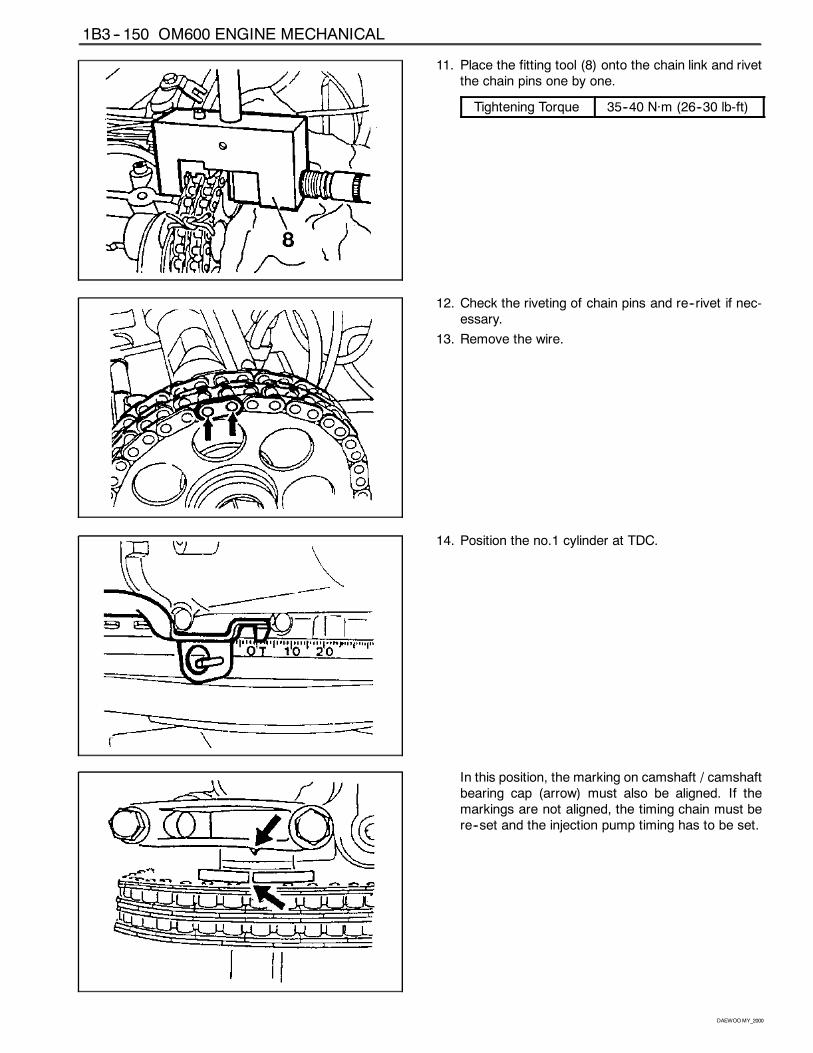
1B3 -- 150 OM600 ENGINE MECHANICAL
DAEWOOMY_2000
11. Place the fitting tool (8) onto the chain link and rivetthe chain pins one by one.
Tightening Torque 35--40 Năm (26--30 lb-ft)
12. Check the riveting of chain pins and re--rivet if nec-essary.
13. Remove the wire.
14. Position the no.1 cylinder at TDC.
In this position, the marking on camshaft / camshaftbearing cap (arrow) must also be aligned. If themarkings are not aligned, the timing chain must bere--set and the injection pump timing has to be set.
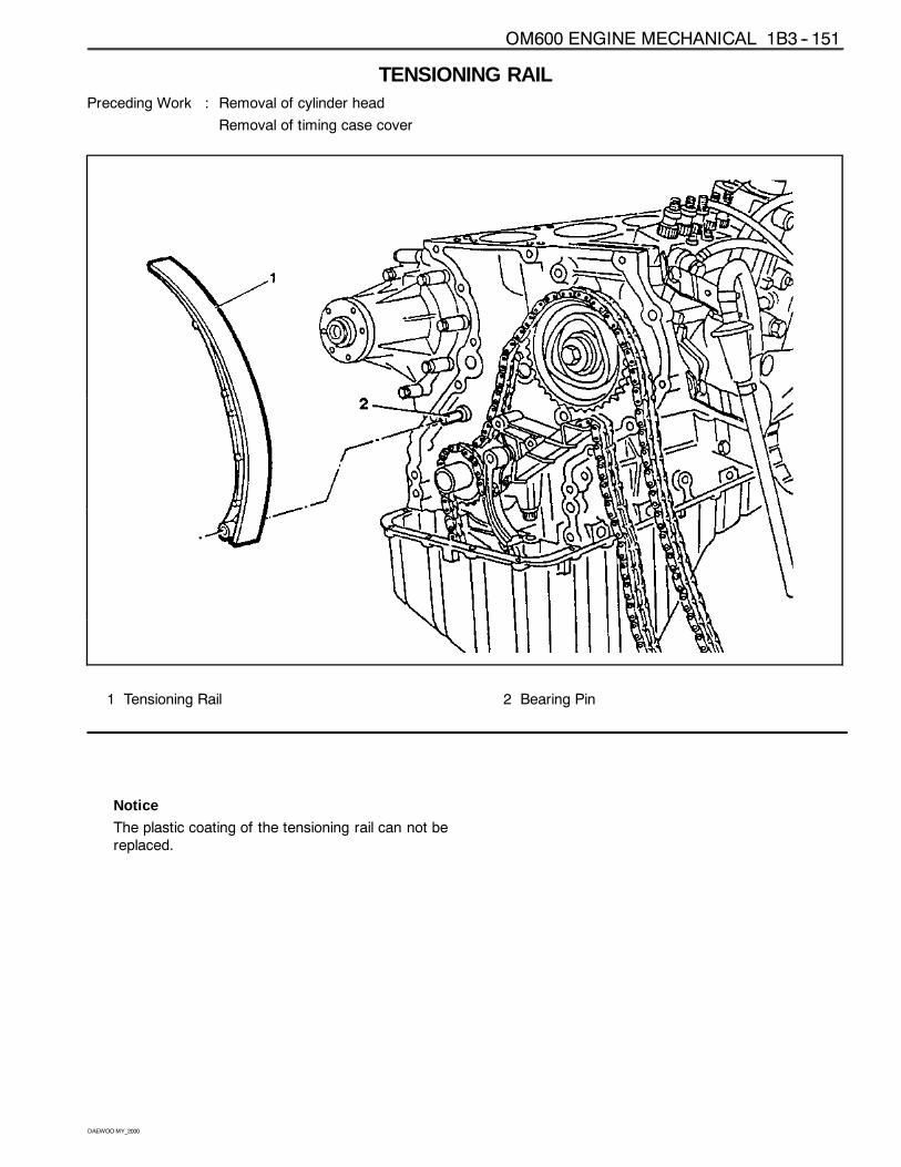
OM600 ENGINE MECHANICAL 1B3 -- 151
DAEWOOMY_2000
TENSIONING RAILPreceding Work : Removal of cylinder head
Removal of timing case cover
1 Tensioning Rail 2 Bearing Pin
Notice
The plastic coating of the tensioning rail can not bereplaced.
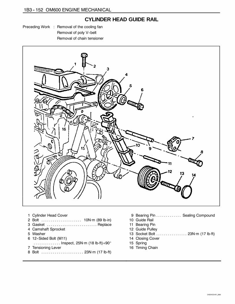
1B3 -- 152 OM600 ENGINE MECHANICAL
DAEWOOMY_2000
CYLINDER HEAD GUIDE RAILPreceding Work : Removal of the cooling fan
Removal of poly V--belt
Removal of chain tensioner
1 Cylinder Head Cover2 Bolt 10Năm (89 lb-in). . . . . . . . . . . . . . . . . . . . .3 Gasket Replace. . . . . . . . . . . . . . . . . . . . . . . . . .4 Camshaft Sprocket5 Washer6 12--Sided Bolt (M11)
Inspect, 25Năm (18 lb-ft)+90_. . . . . . . . . . . . . .7 Tensioning Lever8 Bolt 23Năm (17 lb-ft). . . . . . . . . . . . . . . . . . . . . .
9 Bearing Pin Sealing Compound. . . . . . . . . . . . .10 Guide Rail11 Bearing Pin12 Guide Pulley13 Socket Bolt 23Năm (17 lb-ft). . . . . . . . . . . . . . . .14 Closing Cover15 Spring16 Timing Chain
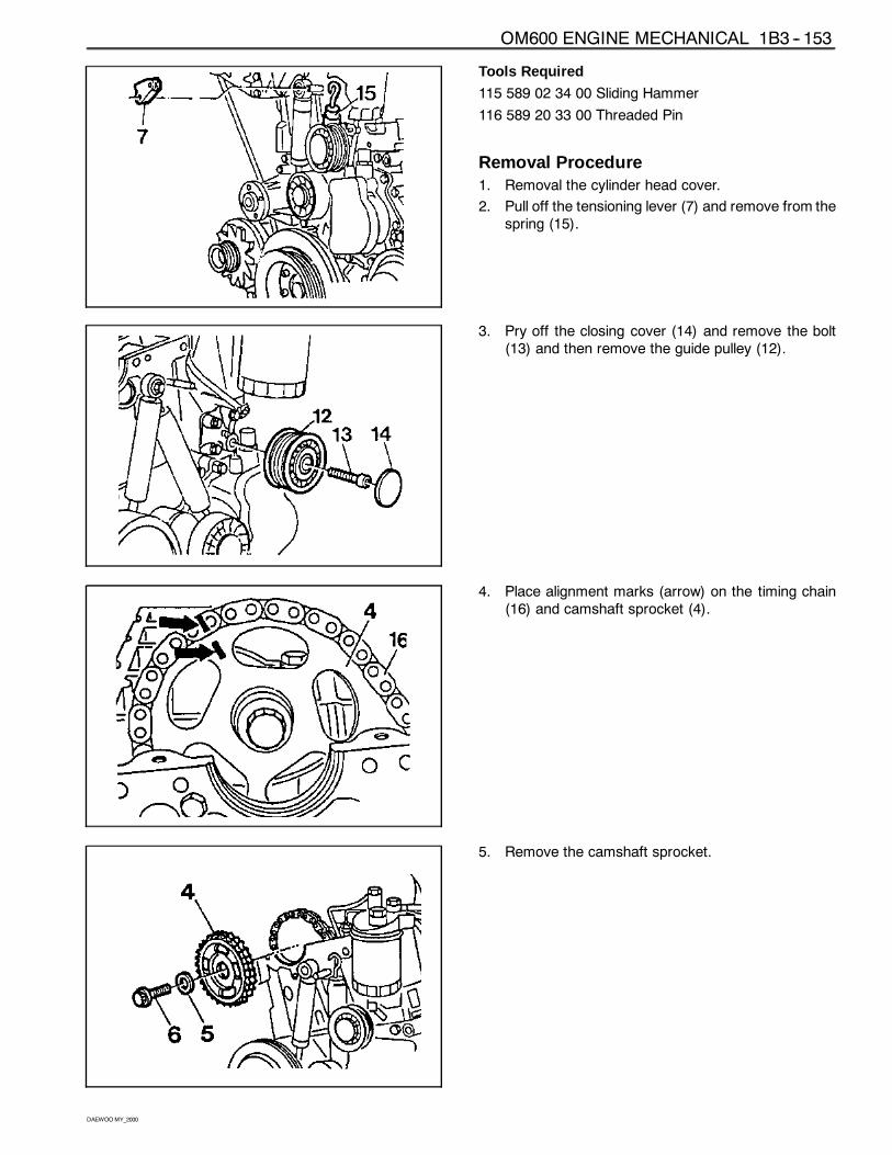
OM600 ENGINE MECHANICAL 1B3 -- 153
DAEWOOMY_2000
Tools Required
115 589 02 34 00 Sliding Hammer
116 589 20 33 00 Threaded Pin
Removal Procedure1. Removal the cylinder head cover.
2. Pull off the tensioning lever (7) and remove from thespring (15).
3. Pry off the closing cover (14) and remove the bolt(13) and then remove the guide pulley (12).
4. Place alignment marks (arrow) on the timing chain(16) and camshaft sprocket (4).
5. Remove the camshaft sprocket.
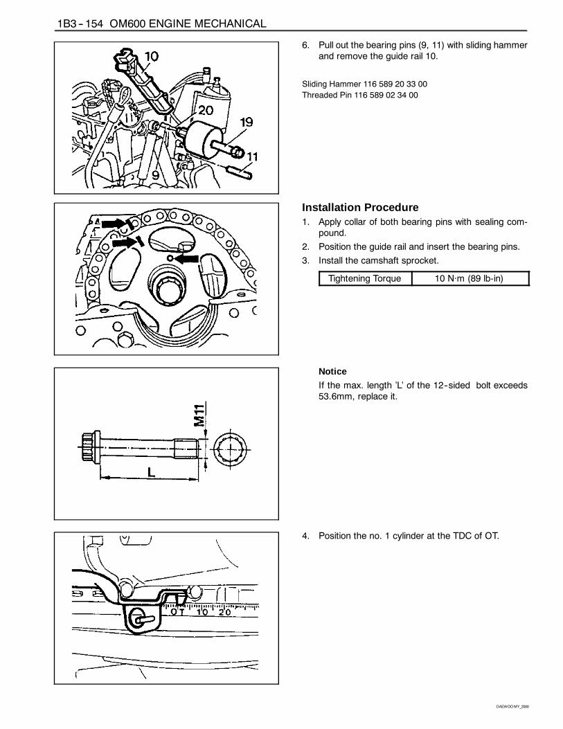
1B3 -- 154 OM600 ENGINE MECHANICAL
DAEWOOMY_2000
6. Pull out the bearing pins (9, 11) with sliding hammerand remove the guide rail 10.
Sliding Hammer 116 589 20 33 00
Threaded Pin 116 589 02 34 00
Installation Procedure1. Apply collar of both bearing pins with sealing com-
pound.
2. Position the guide rail and insert the bearing pins.
3. Install the camshaft sprocket.
Tightening Torque 10 Năm (89 lb-in)
Notice
If the max. length ’L’ of the 12--sided bolt exceeds53.6mm, replace it.
4. Position the no. 1 cylinder at the TDC of OT.
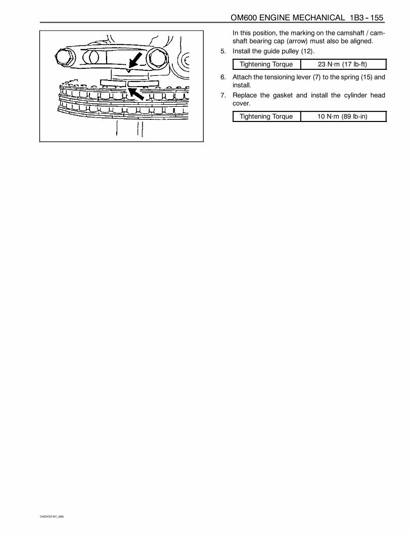
OM600 ENGINE MECHANICAL 1B3 -- 155
DAEWOOMY_2000
In this position, the marking on the camshaft / cam-shaft bearing cap (arrow) must also be aligned.
5. Install the guide pulley (12).
Tightening Torque 23 Năm (17 lb-ft)
6. Attach the tensioning lever (7) to the spring (15) andinstall.
7. Replace the gasket and install the cylinder headcover.
Tightening Torque 10 Năm (89 lb-in)
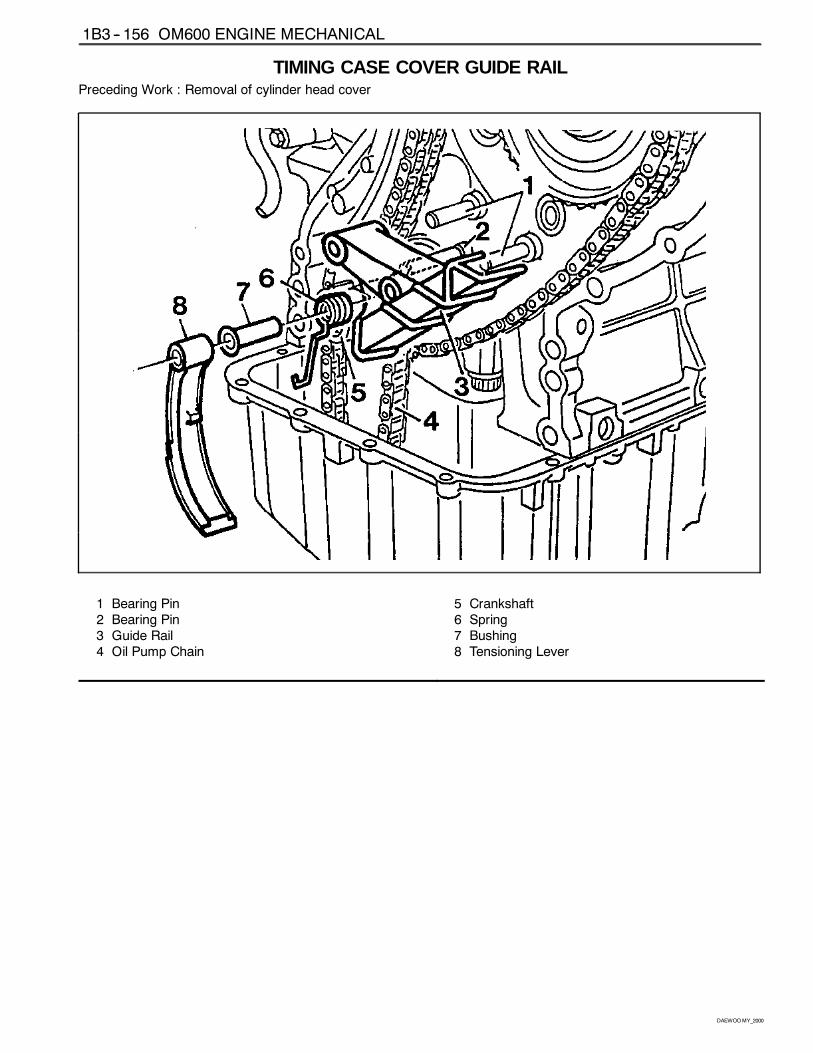
1B3 -- 156 OM600 ENGINE MECHANICAL
DAEWOOMY_2000
TIMING CASE COVER GUIDE RAILPreceding Work : Removal of cylinder head cover
1 Bearing Pin2 Bearing Pin3 Guide Rail4 Oil Pump Chain
5 Crankshaft6 Spring7 Bushing8 Tensioning Lever
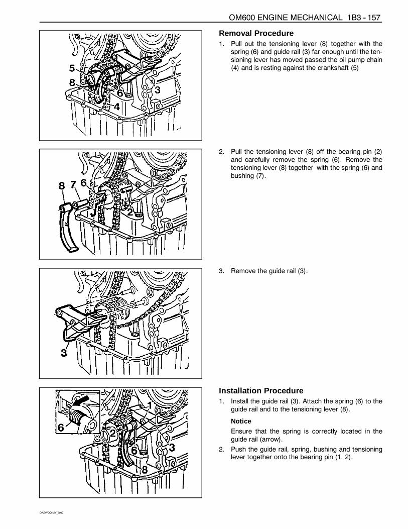
OM600 ENGINE MECHANICAL 1B3 -- 157
DAEWOOMY_2000
Removal Procedure1. Pull out the tensioning lever (8) together with the
spring (6) and guide rail (3) far enough until the ten-sioning lever has moved passed the oil pump chain(4) and is resting against the crankshaft (5)
2. Pull the tensioning lever (8) off the bearing pin (2)and carefully remove the spring (6). Remove thetensioning lever (8) together with the spring (6) andbushing (7).
3. Remove the guide rail (3).
Installation Procedure1. Install the guide rail (3). Attach the spring (6) to the
guide rail and to the tensioning lever (8).
Notice
Ensure that the spring is correctly located in theguide rail (arrow).
2. Push the guide rail, spring, bushing and tensioninglever together onto the bearing pin (1, 2).
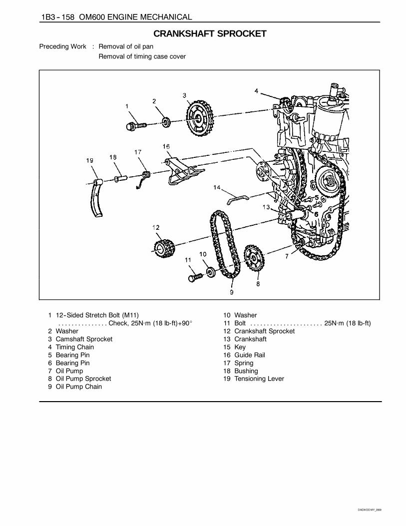
1B3 -- 158 OM600 ENGINE MECHANICAL
DAEWOOMY_2000
CRANKSHAFT SPROCKETPreceding Work : Removal of oil pan
Removal of timing case cover
1 12--Sided Stretch Bolt (M11)Check, 25Năm (18 lb-ft)+90_. . . . . . . . . . . . . . .
2 Washer3 Camshaft Sprocket4 Timing Chain5 Bearing Pin6 Bearing Pin7 Oil Pump8 Oil Pump Sprocket9 Oil Pump Chain
10 Washer11 Bolt 25Năm (18 lb-ft). . . . . . . . . . . . . . . . . . . . . .12 Crankshaft Sprocket13 Crankshaft15 Key16 Guide Rail17 Spring18 Bushing19 Tensioning Lever
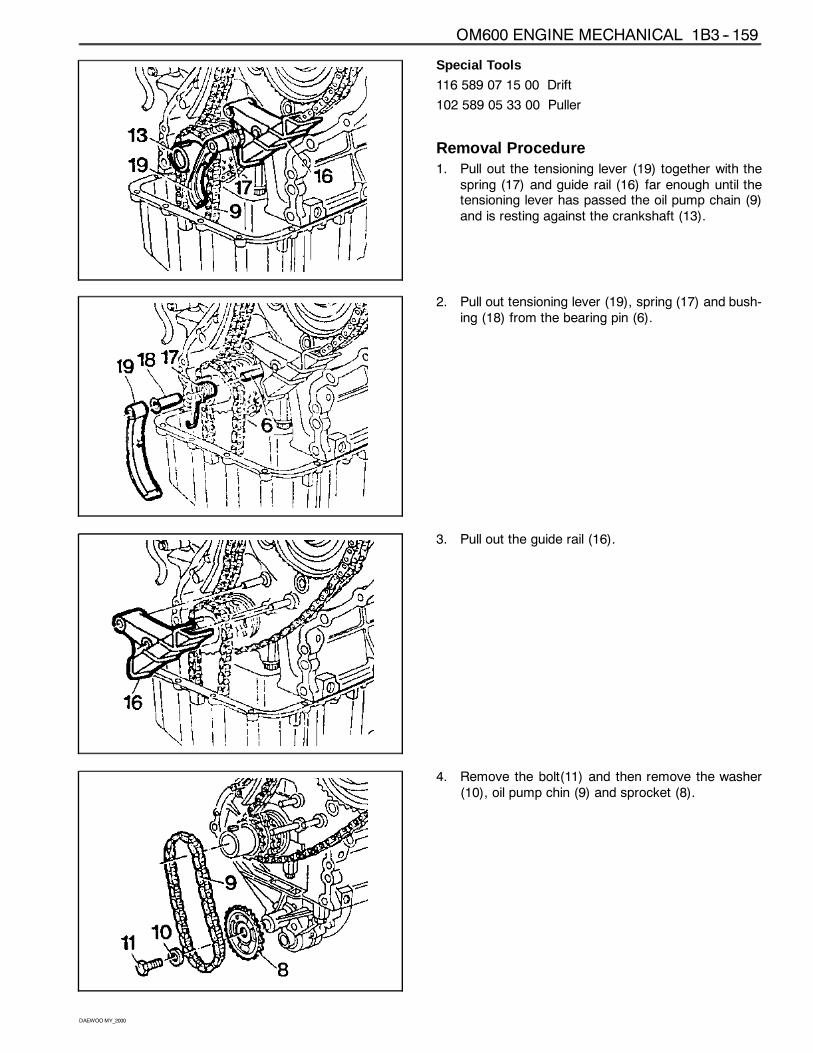
OM600 ENGINE MECHANICAL 1B3 -- 159
DAEWOOMY_2000
Special Tools
116 589 07 15 00 Drift
102 589 05 33 00 Puller
Removal Procedure1. Pull out the tensioning lever (19) together with the
spring (17) and guide rail (16) far enough until thetensioning lever has passed the oil pump chain (9)and is resting against the crankshaft (13).
2. Pull out tensioning lever (19), spring (17) and bush-ing (18) from the bearing pin (6).
3. Pull out the guide rail (16).
4. Remove the bolt(11) and then remove the washer(10), oil pump chin (9) and sprocket (8).
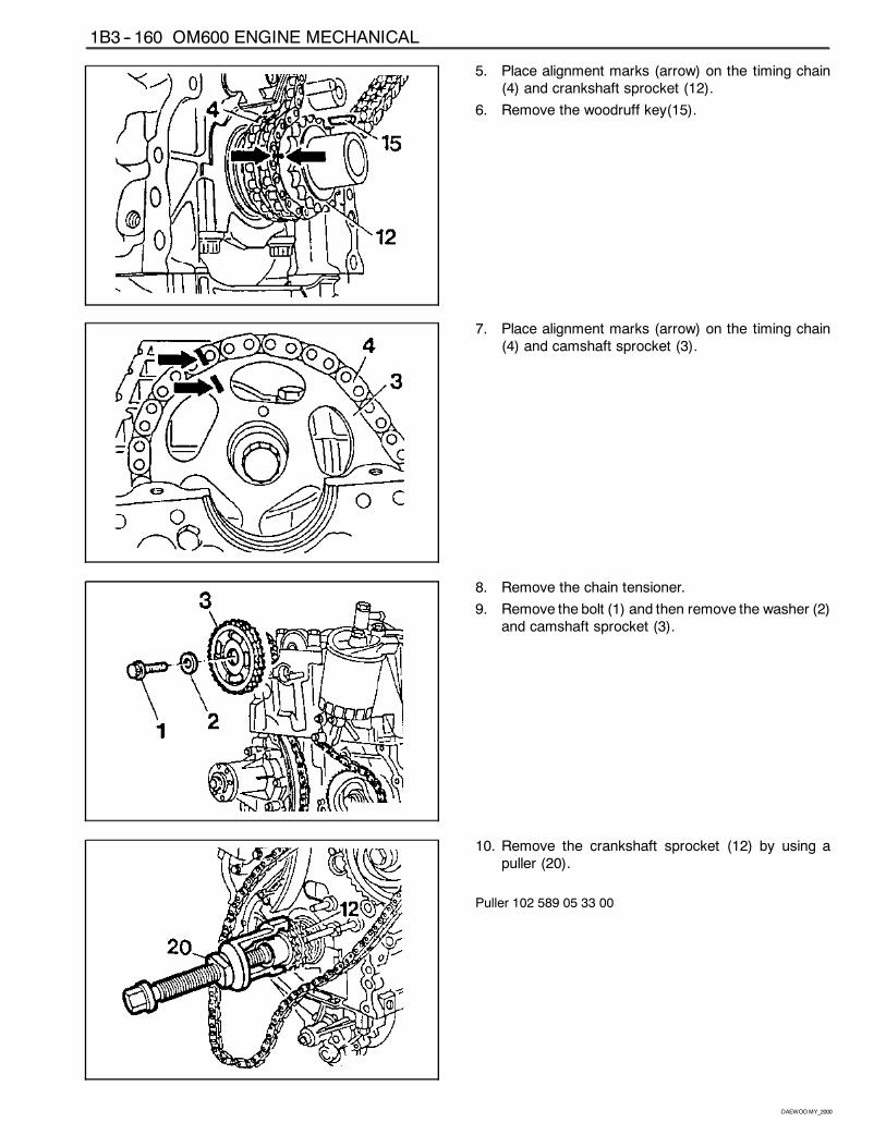
1B3 -- 160 OM600 ENGINE MECHANICAL
DAEWOOMY_2000
5. Place alignment marks (arrow) on the timing chain(4) and crankshaft sprocket (12).
6. Remove the woodruff key(15).
7. Place alignment marks (arrow) on the timing chain(4) and camshaft sprocket (3).
8. Remove the chain tensioner.
9. Remove the bolt (1) and then remove the washer (2)and camshaft sprocket (3).
10. Remove the crankshaft sprocket (12) by using apuller (20).
Puller 102 589 05 33 00
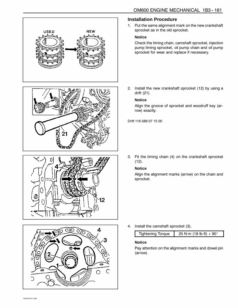
OM600 ENGINE MECHANICAL 1B3 -- 161
DAEWOOMY_2000
Installation Procedure1. Put the same alignment mark on the new crankshaft
sprocket as in the old sprocket.
Notice
Check the timing chain, camshaft sprocket, injectionpump timing sprocket, oil pump chain and oil pumpsprocket for wear and replace if necessary.
2. Install the new crankshaft sprocket (12) by using adrift (21).
Notice
Align the groove of sprocket and woodruff key (ar-row) exactly.
Drift 116 589 07 15 00
3. Fit the timing chain (4) on the crankshaft sprocket(12).
Notice
Align the alignment marks (arrow) on the chain andsprocket.
4. Install the camshaft sprocket (3).
Tightening Torque 25 Năm (18 lb-ft) + 90_
Notice
Pay attention on the alignment marks and dowel pin(arrow).
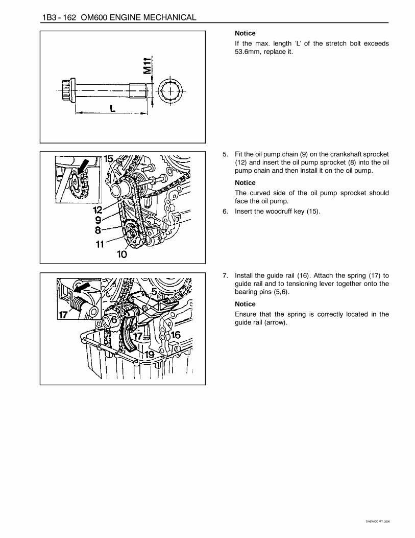
1B3 -- 162 OM600 ENGINE MECHANICAL
DAEWOOMY_2000
Notice
If the max. length ’L’ of the stretch bolt exceeds53.6mm, replace it.
5. Fit the oil pump chain (9) on the crankshaft sprocket(12) and insert the oil pump sprocket (8) into the oilpump chain and then install it on the oil pump.
Notice
The curved side of the oil pump sprocket shouldface the oil pump.
6. Insert the woodruff key (15).
7. Install the guide rail (16). Attach the spring (17) toguide rail and to tensioning lever together onto thebearing pins (5,6).
Notice
Ensure that the spring is correctly located in theguide rail (arrow).
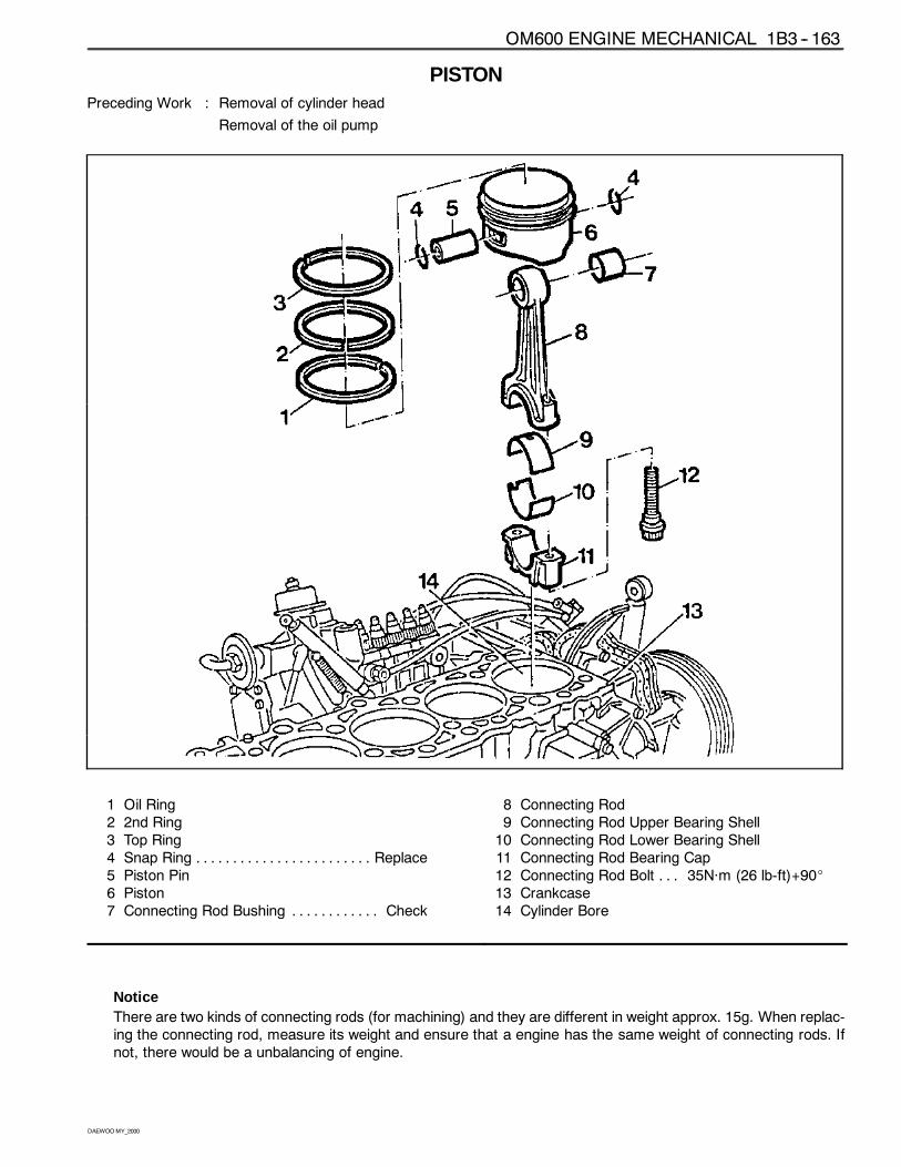
OM600 ENGINE MECHANICAL 1B3 -- 163
DAEWOOMY_2000
PISTONPreceding Work : Removal of cylinder head
Removal of the oil pump
1 Oil Ring2 2nd Ring3 Top Ring4 Snap Ring Replace. . . . . . . . . . . . . . . . . . . . . . . .5 Piston Pin6 Piston7 Connecting Rod Bushing Check. . . . . . . . . . . .
8 Connecting Rod9 Connecting Rod Upper Bearing Shell10 Connecting Rod Lower Bearing Shell11 Connecting Rod Bearing Cap12 Connecting Rod Bolt 35Năm (26 lb-ft)+90_. . .13 Crankcase14 Cylinder Bore
NoticeThere are two kinds of connecting rods (for machining) and they are different in weight approx. 15g. When replac-ing the connecting rod, measure its weight and ensure that a engine has the same weight of connecting rods. Ifnot, there would be a unbalancing of engine.
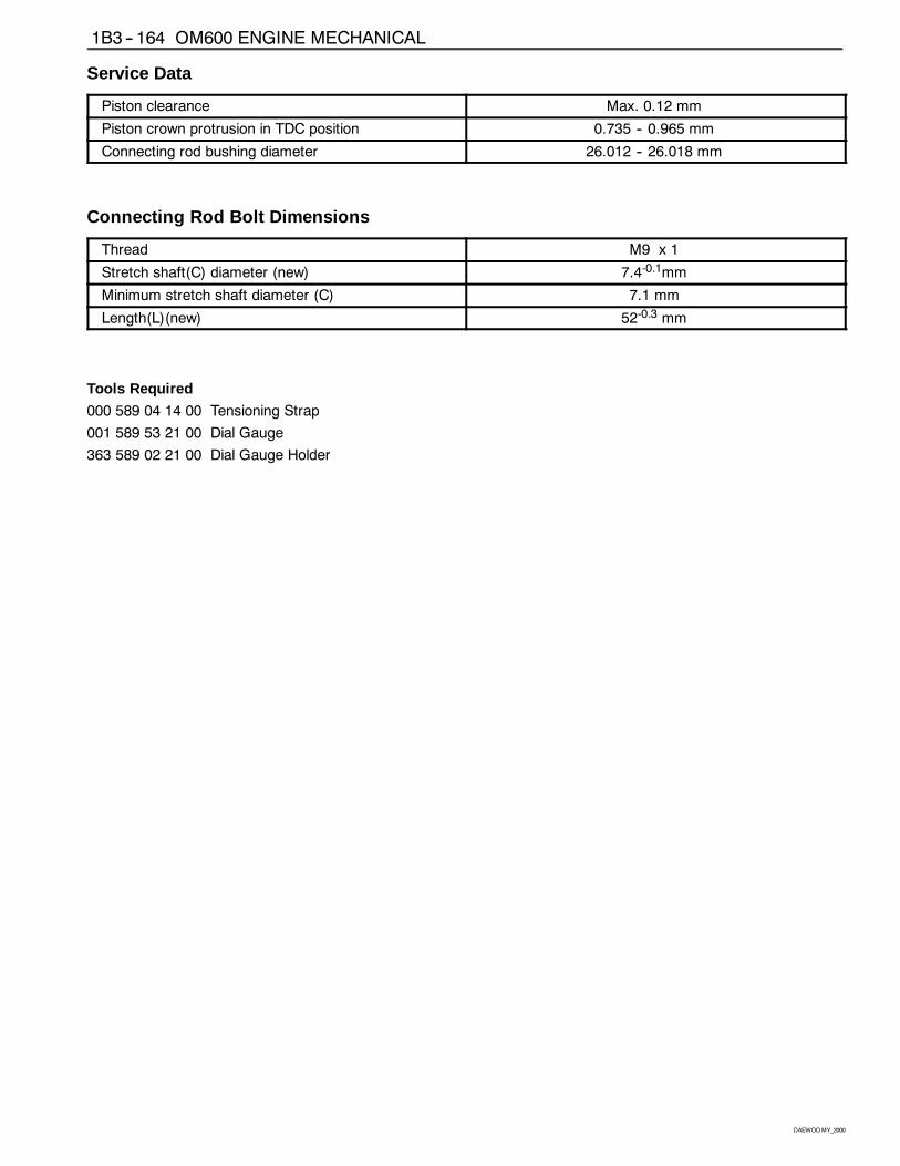
1B3 -- 164 OM600 ENGINE MECHANICAL
DAEWOOMY_2000
Service Data
Piston clearance Max. 0.12 mm
Piston crown protrusion in TDC position 0.735 -- 0.965 mm
Connecting rod bushing diameter 26.012 -- 26.018 mm
Connecting Rod Bolt Dimensions
Thread M9 x 1
Stretch shaft(C) diameter (new) 7.4-0.1mm
Minimum stretch shaft diameter (C) 7.1 mm
Length(L)(new) 52-0.3 mm
Tools Required
000 589 04 14 00 Tensioning Strap
001 589 53 21 00 Dial Gauge
363 589 02 21 00 Dial Gauge Holder
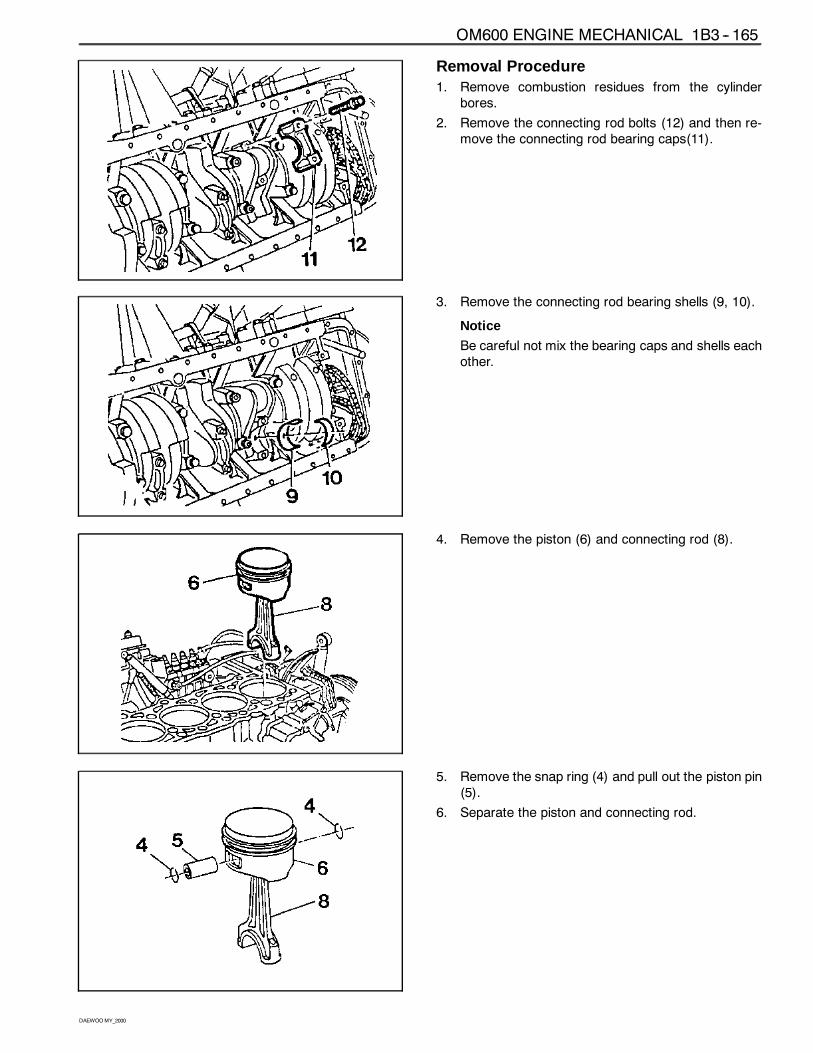
OM600 ENGINE MECHANICAL 1B3 -- 165
DAEWOOMY_2000
Removal Procedure1. Remove combustion residues from the cylinder
bores.
2. Remove the connecting rod bolts (12) and then re-move the connecting rod bearing caps(11).
3. Remove the connecting rod bearing shells (9, 10).
Notice
Be careful not mix the bearing caps and shells eachother.
4. Remove the piston (6) and connecting rod (8).
5. Remove the snap ring (4) and pull out the piston pin(5).
6. Separate the piston and connecting rod.
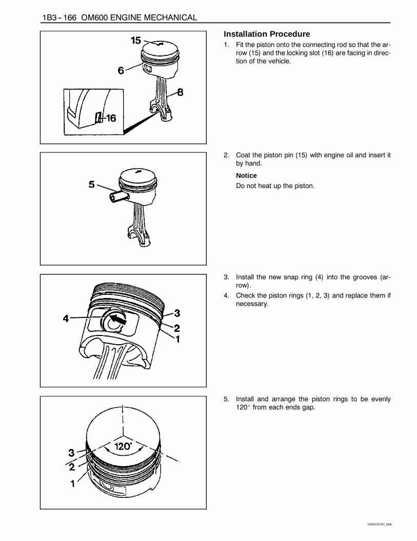
1B3 -- 166 OM600 ENGINE MECHANICAL
DAEWOOMY_2000
Installation Procedure1. Fit the piston onto the connecting rod so that the ar-
row (15) and the locking slot (16) are facing in direc-tion of the vehicle.
2. Coat the piston pin (15) with engine oil and insert itby hand.
Notice
Do not heat up the piston.
3. Install the new snap ring (4) into the grooves (ar-row).
4. Check the piston rings (1, 2, 3) and replace them ifnecessary.
5. Install and arrange the piston rings to be evenly120_ from each ends gap.
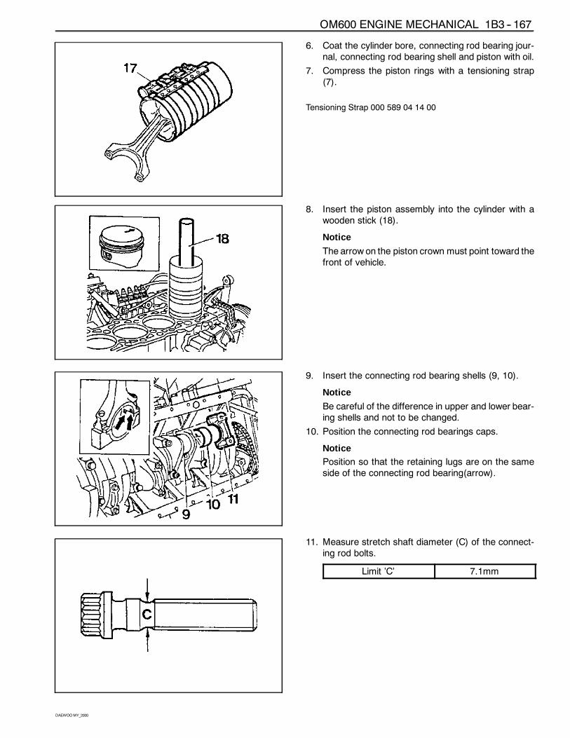
OM600 ENGINE MECHANICAL 1B3 -- 167
DAEWOOMY_2000
6. Coat the cylinder bore, connecting rod bearing jour-nal, connecting rod bearing shell and piston with oil.
7. Compress the piston rings with a tensioning strap(7).
Tensioning Strap 000 589 04 14 00
8. Insert the piston assembly into the cylinder with awooden stick (18).
Notice
The arrow on the piston crown must point toward thefront of vehicle.
9. Insert the connecting rod bearing shells (9, 10).
Notice
Be careful of the difference in upper and lower bear-ing shells and not to be changed.
10. Position the connecting rod bearings caps.
NoticePosition so that the retaining lugs are on the sameside of the connecting rod bearing(arrow).
11. Measure stretch shaft diameter (C) of the connect-ing rod bolts.
Limit ’C’ 7.1mm
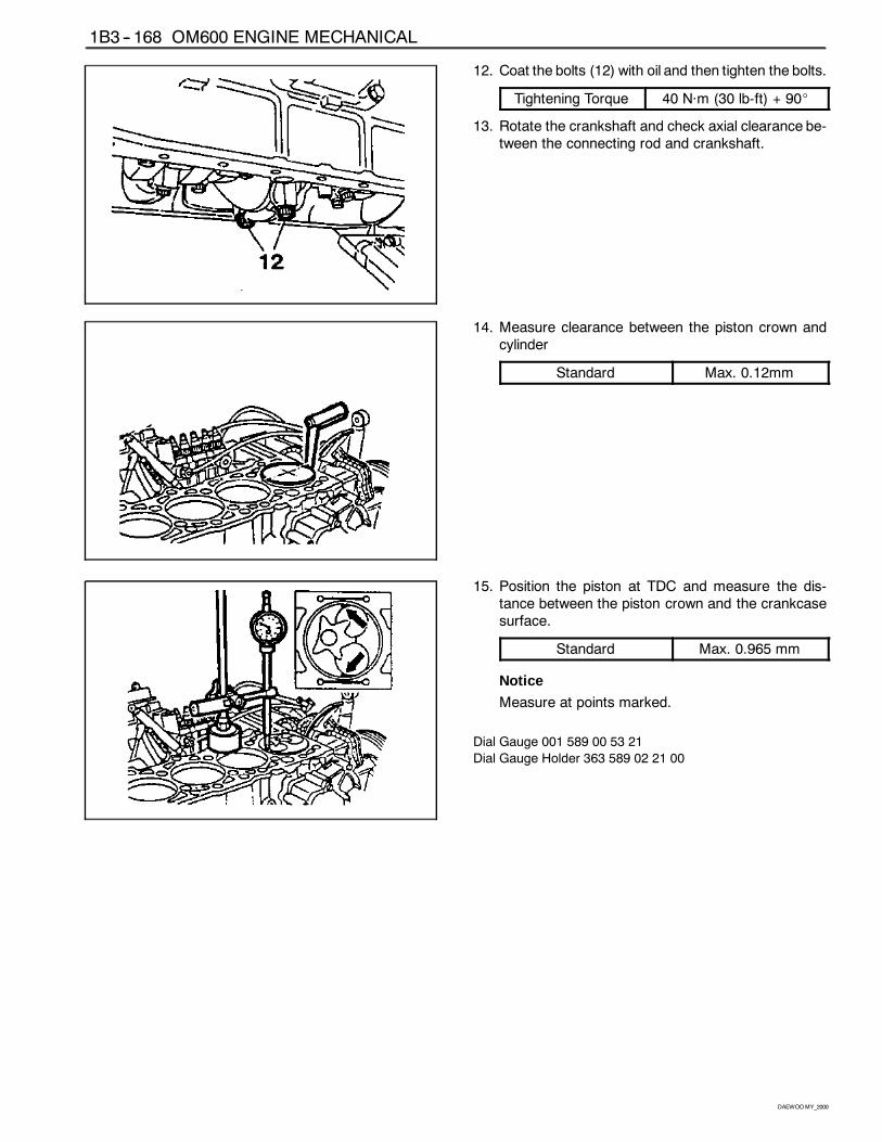
1B3 -- 168 OM600 ENGINE MECHANICAL
DAEWOOMY_2000
12. Coat the bolts (12) with oil and then tighten the bolts.
Tightening Torque 40 Năm (30 lb-ft) + 90_
13. Rotate the crankshaft and check axial clearance be-tween the connecting rod and crankshaft.
14. Measure clearance between the piston crown andcylinder
Standard Max. 0.12mm
15. Position the piston at TDC and measure the dis-tance between the piston crown and the crankcasesurface.
Standard Max. 0.965 mm
Notice
Measure at points marked.
Dial Gauge 001 589 00 53 21
Dial Gauge Holder 363 589 02 21 00
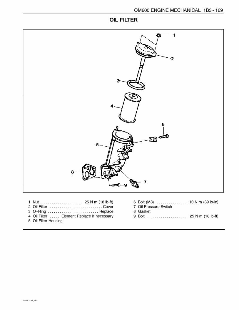
OM600 ENGINE MECHANICAL 1B3 -- 169
DAEWOOMY_2000
OIL FILTER
1 Nut 25 Năm (18 lb-ft). . . . . . . . . . . . . . . . . . . . . .2 Oil Filter Cover. . . . . . . . . . . . . . . . . . . . . . . . . . .3 O--Ring Replace. . . . . . . . . . . . . . . . . . . . . . . . . .4 Oil Filter Element Replace If necessary. . . . .5 Oil Filter Housing
6 Bolt (M8) 10 Năm (89 lb-in). . . . . . . . . . . . . . . .7 Oil Pressure Switch8 Gasket9 Bolt 25 Năm (18 lb-ft). . . . . . . . . . . . . . . . . . . . .
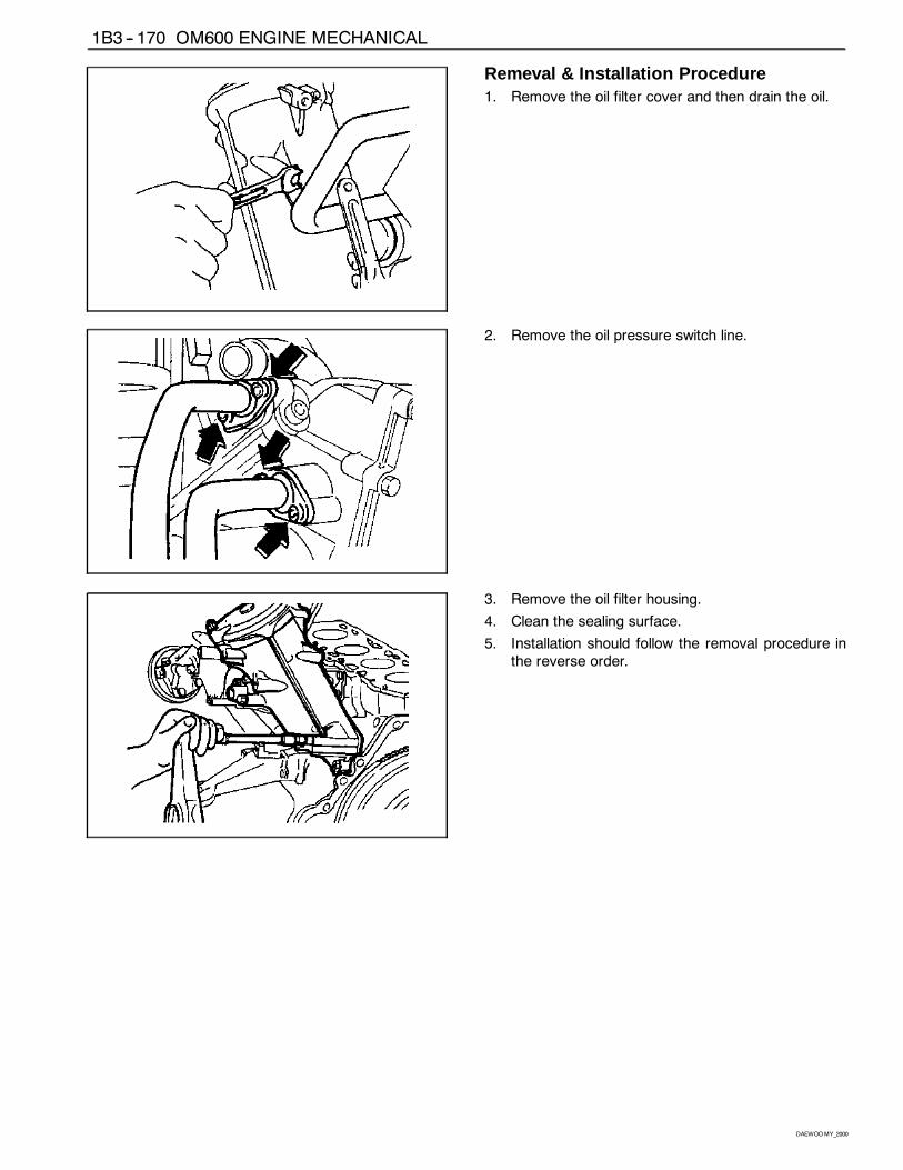
1B3 -- 170 OM600 ENGINE MECHANICAL
DAEWOOMY_2000
Remeval & Installation Procedure1. Remove the oil filter cover and then drain the oil.
2. Remove the oil pressure switch line.
3. Remove the oil filter housing.
4. Clean the sealing surface.
5. Installation should follow the removal procedure inthe reverse order.
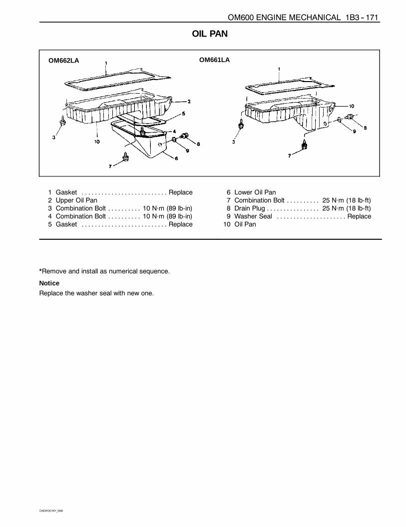
OM600 ENGINE MECHANICAL 1B3 -- 171
DAEWOOMY_2000
OIL PAN
OM662LA OM661LA
1 Gasket Replace. . . . . . . . . . . . . . . . . . . . . . . . . .2 Upper Oil Pan3 Combination Bolt 10 Năm (89 lb-in). . . . . . . . . .4 Combination Bolt 10 Năm (89 lb-in). . . . . . . . . .5 Gasket Replace. . . . . . . . . . . . . . . . . . . . . . . . . .
6 Lower Oil Pan7 Combination Bolt 25 Năm (18 lb-ft). . . . . . . . . .8 Drain Plug 25 Năm (18 lb-ft). . . . . . . . . . . . . . . .9 Washer Seal Replace. . . . . . . . . . . . . . . . . . . . .10 Oil Pan
*Remove and install as numerical sequence.
Notice
Replace the washer seal with new one.
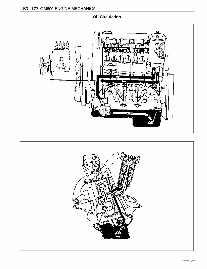
1B3 -- 172 OM600 ENGINE MECHANICAL
DAEWOOMY_2000
Oil Circulation
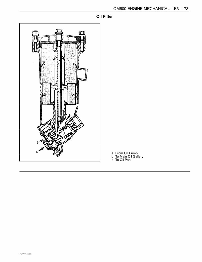
OM600 ENGINE MECHANICAL 1B3 -- 173
DAEWOOMY_2000
Oil Filter
a From Oil Pumpb To Main Oil Galleryc To Oil Pan
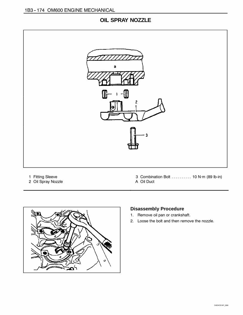
1B3 -- 174 OM600 ENGINE MECHANICAL
DAEWOOMY_2000
OIL SPRAY NOZZLE
1 Fitting Sleeve2 Oil Spray Nozzle
3 Combination Bolt 10 Năm (89 lb-in). . . . . . . . . .A Oil Duct
Disassembly Procedure1. Remove oil pan or crankshaft.
2. Loose the bolt and then remove the nozzle.
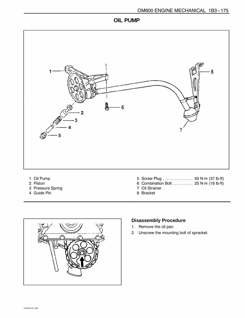
OM600 ENGINE MECHANICAL 1B3 -- 175
DAEWOOMY_2000
OIL PUMP
1 Oil Pump2 Piston3 Pressure Spring4 Guide Pin
5 Screw Plug 50 Năm (37 lb-ft). . . . . . . . . . . . . . .6 Combination Bolt 25 Năm (18 lb-ft). . . . . . . . . .7 Oil Strainer8 Bracket
Disassembly Procedure1. Remove the oil pan.
2. Unscrew the mounting bolt of spracket.
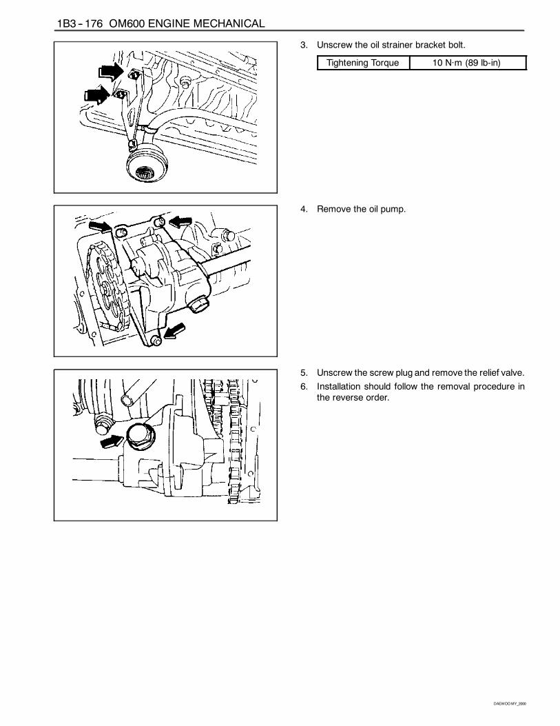
1B3 -- 176 OM600 ENGINE MECHANICAL
DAEWOOMY_2000
3. Unscrew the oil strainer bracket bolt.
Tightening Torque 10 Năm (89 lb-in)
4. Remove the oil pump.
5. Unscrew the screw plug and remove the relief valve.
6. Installation should follow the removal procedure inthe reverse order.
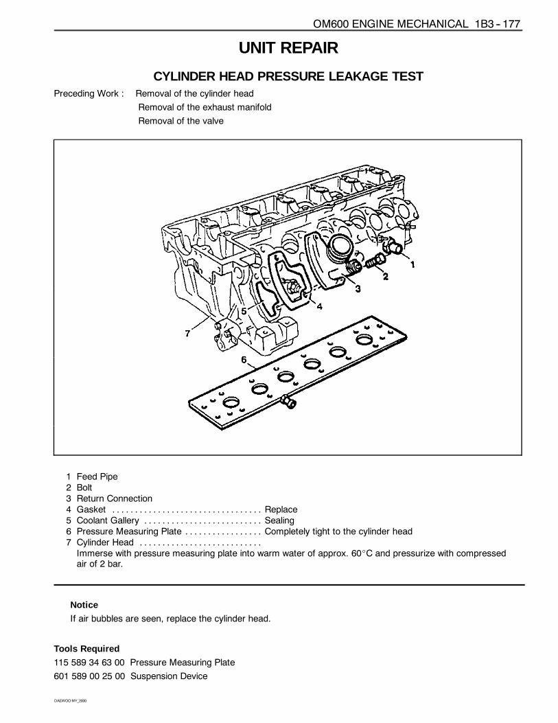
OM600 ENGINE MECHANICAL 1B3 -- 177
DAEWOOMY_2000
UNIT REPAIR
CYLINDER HEAD PRESSURE LEAKAGE TESTPreceding Work : Removal of the cylinder head
Removal of the exhaust manifold
Removal of the valve
1 Feed Pipe2 Bolt3 Return Connection4 Gasket Replace. . . . . . . . . . . . . . . . . . . . . . . . . . . . . . . . .5 Coolant Gallery Sealing. . . . . . . . . . . . . . . . . . . . . . . . . .6 Pressure Measuring Plate Completely tight to the cylinder head. . . . . . . . . . . . . . . . .7 Cylinder Head . . . . . . . . . . . . . . . . . . . . . . . . . . .Immerse with pressure measuring plate into warm water of approx. 60_C and pressurize with compressedair of 2 bar.
Notice
If air bubbles are seen, replace the cylinder head.
Tools Required
115 589 34 63 00 Pressure Measuring Plate
601 589 00 25 00 Suspension Device
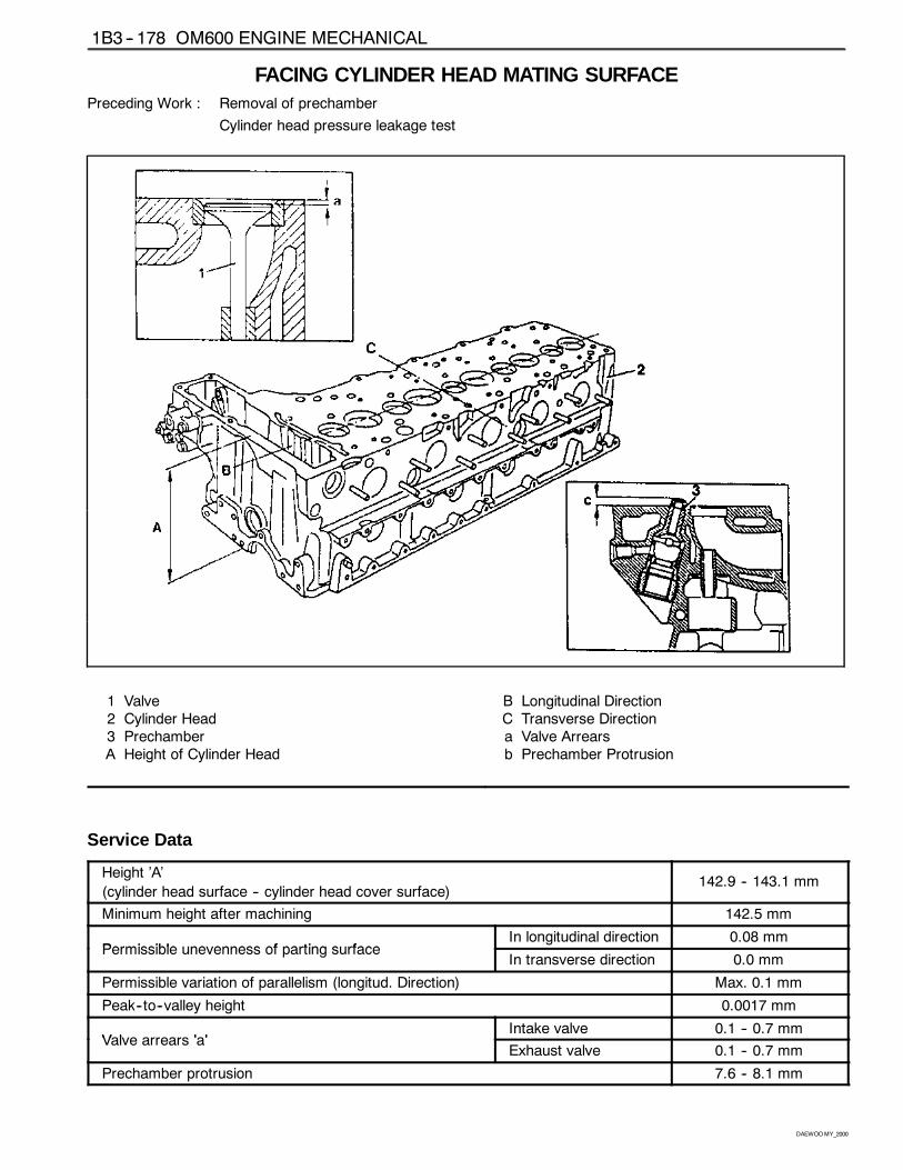
1B3 -- 178 OM600 ENGINE MECHANICAL
DAEWOOMY_2000
FACING CYLINDER HEAD MATING SURFACEPreceding Work : Removal of prechamber
Cylinder head pressure leakage test
1 Valve2 Cylinder Head3 PrechamberA Height of Cylinder Head
B Longitudinal DirectionC Transverse Directiona Valve Arrearsb Prechamber Protrusion
Service Data
Height ’A’
(cylinder head surface -- cylinder head cover surface)142.9 -- 143.1 mm
Minimum height after machining 142.5 mm
Permissible unevenness of parting surfaceIn longitudinal direction 0.08 mm
Permissible unevenness of parting surfaceIn transverse direction 0.0 mm
Permissible variation of parallelism (longitud. Direction) Max. 0.1 mm
Peak--to--valley height 0.0017 mm
V l ’ ’Intake valve 0.1 -- 0.7 mm
Valve arrears ’a’Exhaust valve 0.1 -- 0.7 mm
Prechamber protrusion 7.6 -- 8.1 mm
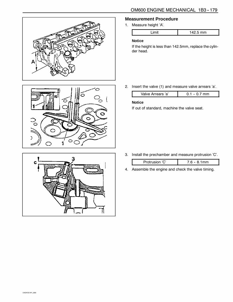
OM600 ENGINE MECHANICAL 1B3 -- 179
DAEWOOMY_2000
Measurement Procedure1. Measure height ’A’.
Limit 142.5 mm
Notice
If the height is less than 142.5mm, replace the cylin-der head.
2. Insert the valve (1) and measure valve arrears ’a’.
Valve Arrears ’a’ 0.1 -- 0.7 mm
Notice
If out of standard, machine the valve seat.
3. Install the prechamber and measure protrusion ’C’.
Protrusion ’C’ 7.6 -- 8.1mm
4. Assemble the engine and check the valve timing.
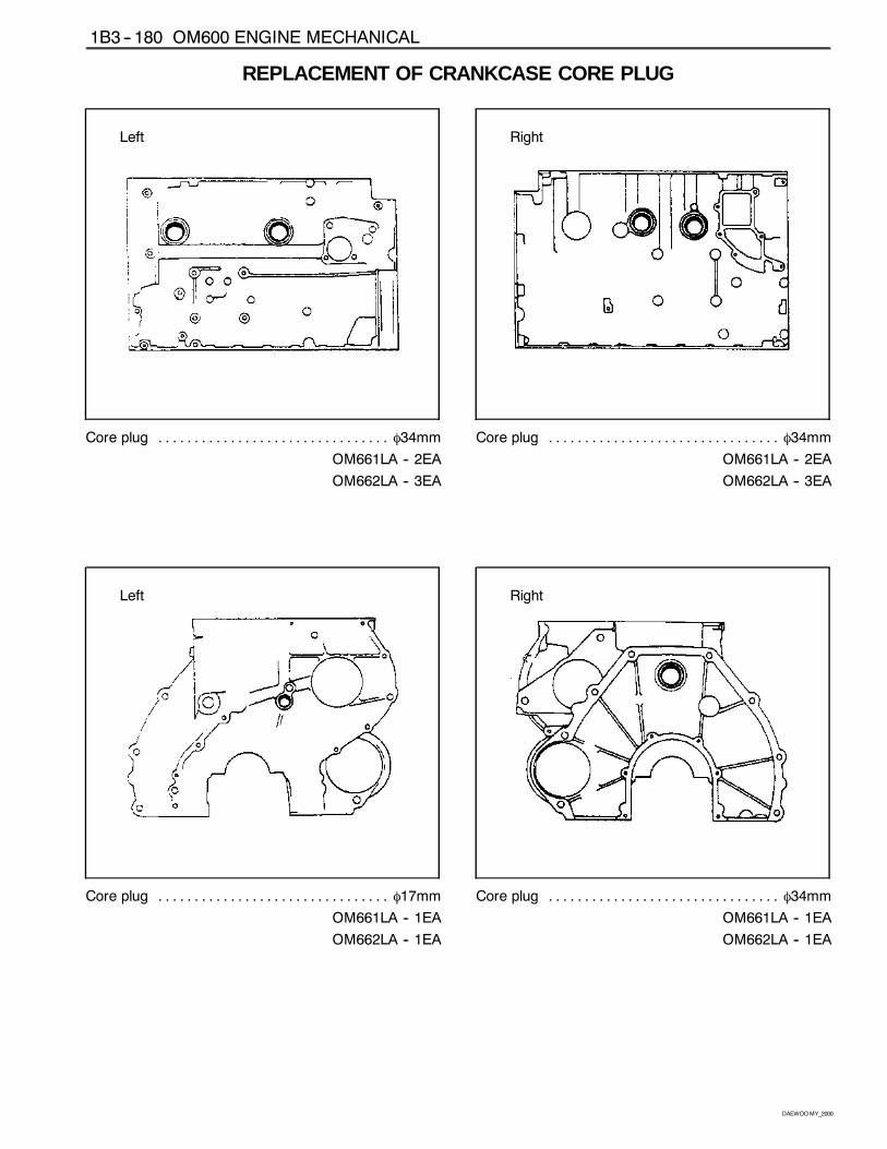
1B3 -- 180 OM600 ENGINE MECHANICAL
DAEWOOMY_2000
REPLACEMENT OF CRANKCASE CORE PLUG
Left
Core plug φ34mm. . . . . . . . . . . . . . . . . . . . . . . . . . . . . . . .
OM661LA -- 2EA
OM662LA -- 3EA
Right
Core plug φ34mm. . . . . . . . . . . . . . . . . . . . . . . . . . . . . . . .
OM661LA -- 2EA
OM662LA -- 3EA
Left
Core plug φ17mm. . . . . . . . . . . . . . . . . . . . . . . . . . . . . . . .
OM661LA -- 1EA
OM662LA -- 1EA
Right
Core plug φ34mm. . . . . . . . . . . . . . . . . . . . . . . . . . . . . . . .
OM661LA -- 1EA
OM662LA -- 1EA
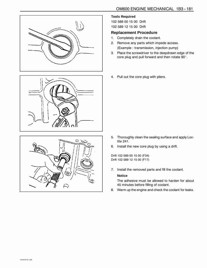
OM600 ENGINE MECHANICAL 1B3 -- 181
DAEWOOMY_2000
Tools Required
102 589 00 15 00 Drift
102 589 12 15 00 Drift
Replacement Procedure1. Completely drain the coolant.
2. Remove any parts which impede access.
(Example : transmission, injection pump)
3. Place the screwdriver to the deepdrawn edge of thecore plug and pull forward and then rotate 90_.
4. Pull out the core plug with pliers.
5. Thoroughly clean the sealing surface and apply Loc-tite 241.
6. Install the new core plug by using a drift.
Drift 102 589 00 15 00 (F34)
Drift 102 589 12 15 00 (F17)
7. Install the removed parts and fill the coolant.
Notice
The adhesive must be allowed to harden for about45 minutes before filling of coolant.
8. Warm up the engine and check the coolant for leaks.
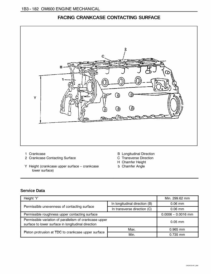
1B3 -- 182 OM600 ENGINE MECHANICAL
DAEWOOMY_2000
FACING CRANKCASE CONTACTING SURFACE
1 Crankcase2 Crankcase Contacting Surface
Y Height (crankcase upper surface -- crankcaselower surface)
B Longitudinal DirectionC Transverse DirectionH Chamfer Heightb Chamfer Angle
Service Data
Height ’Y’ Min. 299.62 mm
Permissible unevenness of contacting surfaceIn longitudinal direction (B) 0.06 mm
Permissible unevenness of contacting surfaceIn transverse direction (C) 0.06 mm
Permissible roughness upper contacting surface 0.0006 -- 0.0016 mm
Permissible variation of parallelism of crankcase upper
surface to lower surface in longitudinal direction0.05 mm
Pi t t i t TDC t k fMax. 0.965 mm
Piston protrusion at TDC to crankcase upper surfaceMin. 0.735 mm
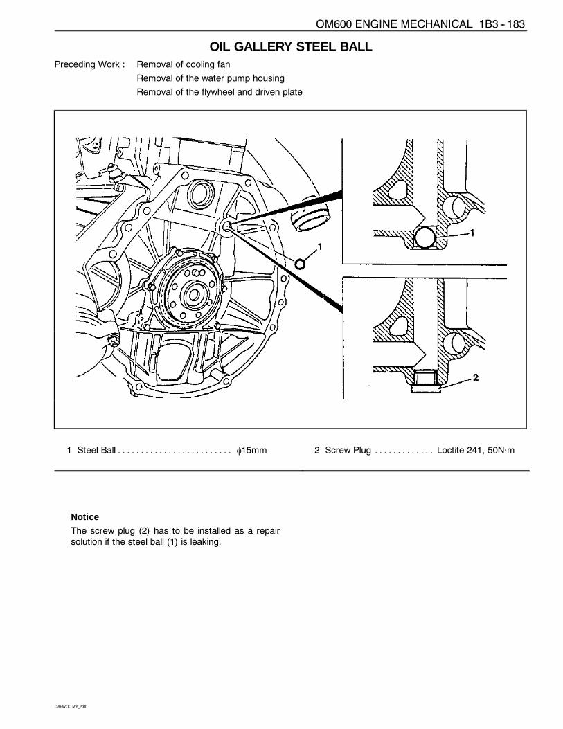
OM600 ENGINE MECHANICAL 1B3 -- 183
DAEWOOMY_2000
OIL GALLERY STEEL BALLPreceding Work : Removal of cooling fan
Removal of the water pump housing
Removal of the flywheel and driven plate
1 Steel Ball φ15mm. . . . . . . . . . . . . . . . . . . . . . . . . 2 Screw Plug Loctite 241, 50Năm. . . . . . . . . . . . .
Notice
The screw plug (2) has to be installed as a repairsolution if the steel ball (1) is leaking.
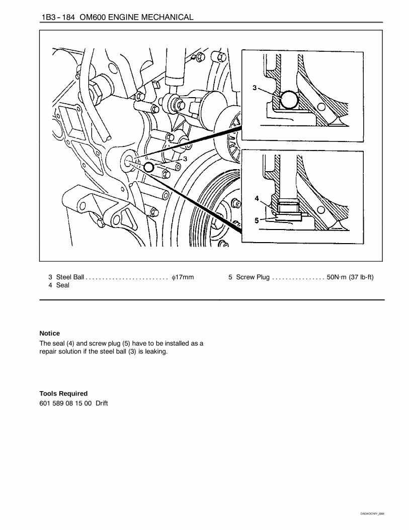
1B3 -- 184 OM600 ENGINE MECHANICAL
DAEWOOMY_2000
3 Steel Ball φ17mm. . . . . . . . . . . . . . . . . . . . . . . . .4 Seal
5 Screw Plug 50Năm (37 lb-ft). . . . . . . . . . . . . . . .
Notice
The seal (4) and screw plug (5) have to be installed as arepair solution if the steel ball (3) is leaking.
Tools Required601 589 08 15 00 Drift
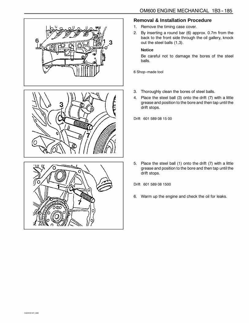
OM600 ENGINE MECHANICAL 1B3 -- 185
DAEWOOMY_2000
Removal & Installation Procedure1. Remove the timing case cover.
2. By inserting a round bar (6) approx. 0.7m from theback to the front side through the oil gallery, knockout the steel balls (1,3).
Notice
Be careful not to damage the bores of the steelballs.
6 Shop--made tool
3. Thoroughly clean the bores of steel balls.
4. Place the steel ball (3) onto the drift (7) with a littlegrease and position to the bore and then tap until thedrift stops.
Drift 601 589 08 15 00
5. Place the steel ball (1) onto the drift (7) with a littlegrease and position to the bore and then tap until thedrift stops.
Drift 601 589 08 1500
6. Warm up the engine and check the oil for leaks.
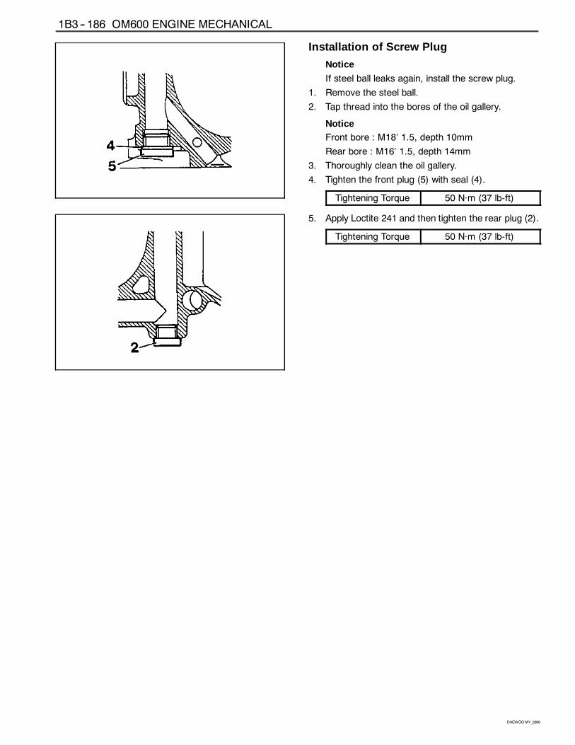
1B3 -- 186 OM600 ENGINE MECHANICAL
DAEWOOMY_2000
Installation of Screw Plug
Notice
If steel ball leaks again, install the screw plug.
1. Remove the steel ball.
2. Tap thread into the bores of the oil gallery.
NoticeFront bore : M18′ 1.5, depth 10mm
Rear bore : M16′ 1.5, depth 14mm
3. Thoroughly clean the oil gallery.
4. Tighten the front plug (5) with seal (4).
Tightening Torque 50 Năm (37 lb-ft)
5. Apply Loctite 241 and then tighten the rear plug (2).
Tightening Torque 50 Năm (37 lb-ft)
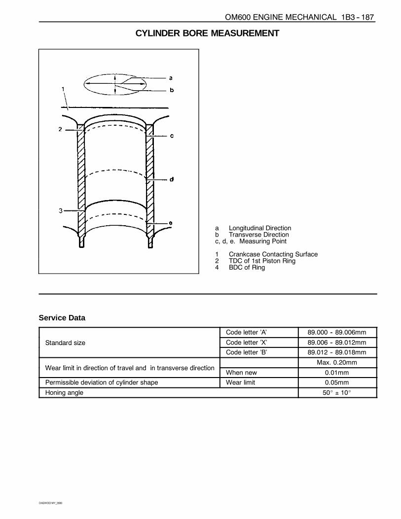
OM600 ENGINE MECHANICAL 1B3 -- 187
DAEWOOMY_2000
CYLINDER BORE MEASUREMENT
a Longitudinal Directionb Transverse Directionc, d, e. Measuring Point
1 Crankcase Contacting Surface2 TDC of 1st Piston Ring4 BDC of Ring
Service Data
Code letter ’A’ 89.000 -- 89.006mm
Standard size Code letter ’X’ 89.006 -- 89.012mmStandard size
Code letter ’B’ 89.012 -- 89.018mm
Wear limit in direction of travel and in transverse directionMax. 0.20mm
Wear limit in direction of travel and in transverse directionWhen new 0.01mm
Permissible deviation of cylinder shape Wear limit 0.05mm
Honing angle 50_ ± 10_