Embed Size (px)
Citation preview
(800) 846-9659 equalizersystems.com
AUTO-LEVEL
Operation and Warranty Guide Effective 2012
Revision- April 2013
TABLE OF CONTENTS
Precaution / Warnings ..................................................................................................................... 2 AUTO-LEVEL System Operation ...................................................................................................... 3-4
Helpful Hints .................................................................................................................................... 5
Maintenance .................................................................................................................................... 6
Manual Override Procedures .......................................................................................................... 7-8
Wiring and Hose Connection Guides ............................................................................................. 9-10
Troubleshooting .......................................................................................................................... …11-13
Equalizer Systems Warranty .......................................................................................................................14
Important Warnings and Precautions
WARNING READ ENTIRE INSTRUCTIONS AND ALL PRECAUTIONS PRIOR TO INSTALLING, USING, OR
TROUBLESHOOTING THIS EQUIPMENT
The system operates using hydraulic fluid under high pressure. Extreme fluid pressure can be present even if the system is not operating. System forces and pressures can cause severe injury or death if used improperly or modified. Service work should only be performed by trained technicians.
Do not attempt to operate any portion of the hydraulic systems when the vehicle is in
motion.
Visually confirm that all leveling jacks are retracted prior to travel.
Make sure there are no obstructions in the extend or retract paths of the jacks or slideouts.
Do not use the leveling jacks to lift the unit to perform any kind of service work or to
change tires. The system is designed as a leveling and stabilizing system and is not meant to lift the coach off the ground.
Do not go under vehicle when leveling jacks are extended.
Do not operate any system functions while anyone is under the coach.
Do not allow excessive motion in the coach during the AUTO-LEVEL operation. This
could cause the system to level improperly.
Modification of any factory-supplied item may result in the denial of all warranty claims. Call
Equalizer Systems Technical Support prior to any modifications.
Do not attempt any technical repairs without first consulting the troubleshooting guide in this manual and/or calling Equalizer Systems Technical Support at (800) 845-9659. Failure to do so may result in denial of warranty claims.
2
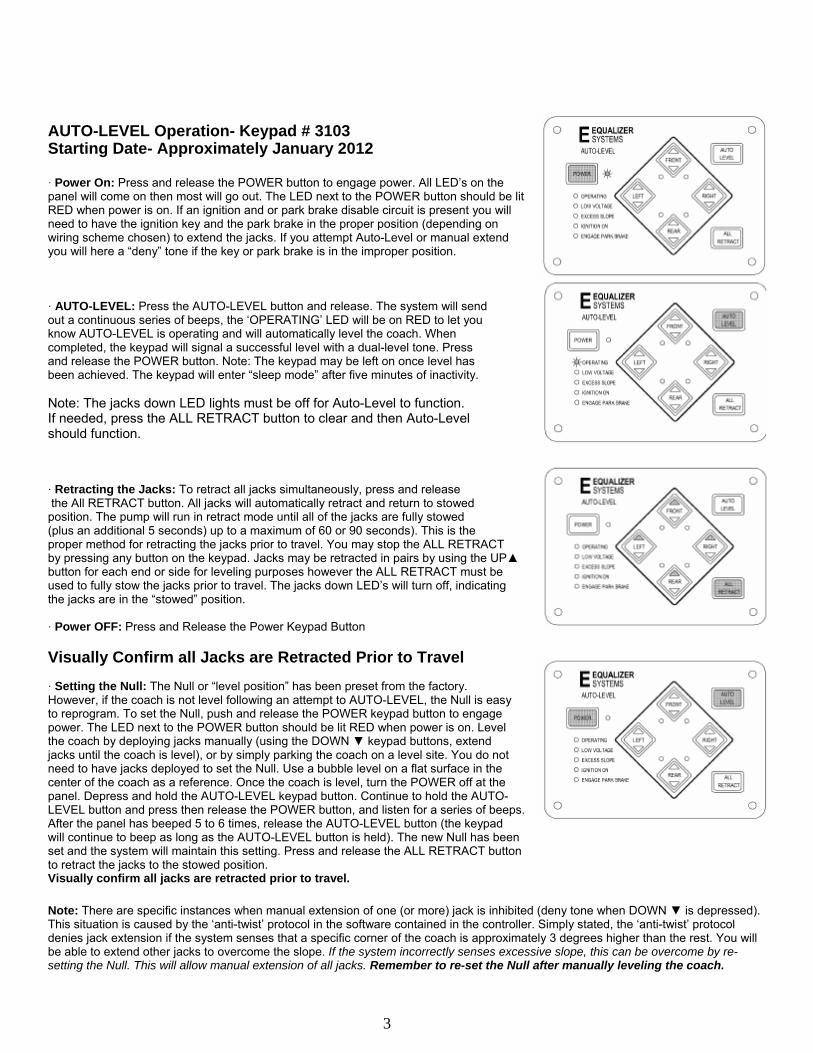
AUTO-LEVEL Operation- Keypad # 3103 Starting Date- Approximately January 2012
· Power On: Press and release the POWER button to engage power. All LED’s on the panel will come on then most will go out. The LED next to the POWER button should be lit RED when power is on. If an ignition and or park brake disable circuit is present you will need to have the ignition key and the park brake in the proper position (depending on wiring scheme chosen) to extend the jacks. If you attempt Auto-Level or manual extend you will here a “deny” tone if the key or park brake is in the improper position.
· AUTO-LEVEL: Press the AUTO-LEVEL button and release. The system will send out a continuous series of beeps, the ‘OPERATING’ LED will be on RED to let you know AUTO-LEVEL is operating and will automatically level the coach. When completed, the keypad will signal a successful level with a dual-level tone. Press and release the POWER button. Note: The keypad may be left on once level has been achieved. The keypad will enter “sleep mode” after five minutes of inactivity.
Note: The jacks down LED lights must be off for Auto-Level to function. If needed, press the ALL RETRACT button to clear and then Auto-Level should function.
· Retracting the Jacks: To retract all jacks simultaneously, press and release the All RETRACT button. All jacks will automatically retract and return to stowed
position. The pump will run in retract mode until all of the jacks are fully stowed (plus an additional 5 seconds) up to a maximum of 60 or 90 seconds). This is the proper method for retracting the jacks prior to travel. You may stop the ALL RETRACT by pressing any button on the keypad. Jacks may be retracted in pairs by using the UP▲ button for each end or side for leveling purposes however the ALL RETRACT must be used to fully stow the jacks prior to travel. The jacks down LED’s will turn off, indicating the jacks are in the “stowed” position.
· Power OFF: Press and Release the Power Keypad Button
Visually Confirm all Jacks are Retracted Prior to Travel
· Setting the Null: The Null or “level position” has been preset from the factory. However, if the coach is not level following an attempt to AUTO-LEVEL, the Null is easy to reprogram. To set the Null, push and release the POWER keypad button to engage power. The LED next to the POWER button should be lit RED when power is on. Level the coach by deploying jacks manually (using the DOWN ▼ keypad buttons, extend jacks until the coach is level), or by simply parking the coach on a level site. You do not need to have jacks deployed to set the Null. Use a bubble level on a flat surface in the center of the coach as a reference. Once the coach is level, turn the POWER off at the panel. Depress and hold the AUTO-LEVEL keypad button. Continue to hold the AUTO- LEVEL button and press then release the POWER button, and listen for a series of beeps. After the panel has beeped 5 to 6 times, release the AUTO-LEVEL button (the keypad will continue to beep as long as the AUTO-LEVEL button is held). The new Null has been set and the system will maintain this setting. Press and release the ALL RETRACT button to retract the jacks to the stowed position. Visually confirm all jacks are retracted prior to travel.
Note: There are specific instances when manual extension of one (or more) jack is inhibited (deny tone when DOWN ▼ is depressed). This situation is caused by the ‘anti-twist’ protocol in the software contained in the controller. Simply stated, the ‘anti-twist’ protocol denies jack extension if the system senses that a specific corner of the coach is approximately 3 degrees higher than the rest. You will be able to extend other jacks to overcome the slope. If the system incorrectly senses excessive slope, this can be overcome by re- setting the Null. This will allow manual extension of all jacks. Remember to re-set the Null after manually leveling the coach.
3
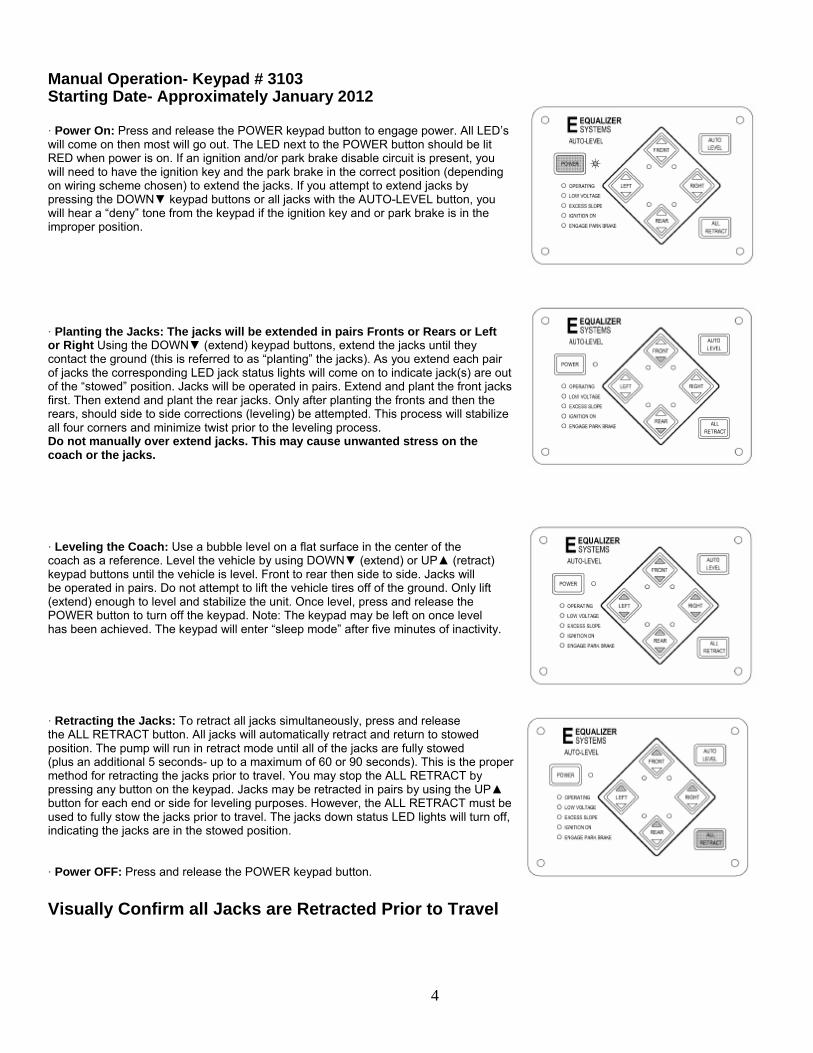
Manual Operation- Keypad # 3103 Starting Date- Approximately January 2012
· Power On: Press and release the POWER keypad button to engage power. All LED’s will come on then most will go out. The LED next to the POWER button should be lit RED when power is on. If an ignition and/or park brake disable circuit is present, you will need to have the ignition key and the park brake in the correct position (depending on wiring scheme chosen) to extend the jacks. If you attempt to extend jacks by pressing the DOWN▼ keypad buttons or all jacks with the AUTO-LEVEL button, you will hear a “deny” tone from the keypad if the ignition key and or park brake is in the improper position.
· Planting the Jacks: The jacks will be extended in pairs Fronts or Rears or Left or Right Using the DOWN▼ (extend) keypad buttons, extend the jacks until they contact the ground (this is referred to as “planting” the jacks). As you extend each pair of jacks the corresponding LED jack status lights will come on to indicate jack(s) are out of the “stowed” position. Jacks will be operated in pairs. Extend and plant the front jacks first. Then extend and plant the rear jacks. Only after planting the fronts and then the rears, should side to side corrections (leveling) be attempted. This process will stabilize all four corners and minimize twist prior to the leveling process. Do not manually over extend jacks. This may cause unwanted stress on the coach or the jacks.
· Leveling the Coach: Use a bubble level on a flat surface in the center of the coach as a reference. Level the vehicle by using DOWN▼ (extend) or UP▲ (retract) keypad buttons until the vehicle is level. Front to rear then side to side. Jacks will be operated in pairs. Do not attempt to lift the vehicle tires off of the ground. Only lift (extend) enough to level and stabilize the unit. Once level, press and release the POWER button to turn off the keypad. Note: The keypad may be left on once level has been achieved. The keypad will enter “sleep mode” after five minutes of inactivity.
· Retracting the Jacks: To retract all jacks simultaneously, press and release the ALL RETRACT button. All jacks will automatically retract and return to stowed position. The pump will run in retract mode until all of the jacks are fully stowed (plus an additional 5 seconds- up to a maximum of 60 or 90 seconds). This is the proper method for retracting the jacks prior to travel. You may stop the ALL RETRACT by pressing any button on the keypad. Jacks may be retracted in pairs by using the UP▲ button for each end or side for leveling purposes. However, the ALL RETRACT must be used to fully stow the jacks prior to travel. The jacks down status LED lights will turn off, indicating the jacks are in the stowed position.
· Power OFF: Press and release the POWER keypad button.
Visually Confirm all Jacks are Retracted Prior to Travel
4
Keypad Indicator LED’s
There are ten (10) LED indicators on the AUTO-LEVEL keypad. The functions of these LED’s are detailed below.
During typical operation, the LED’s on the bottom left hand corner of the keypad should NOT be illuminated. The only LED that should light is the ‘OPERATING’ LED, which should flash during operation.
‘POWER’ LED .......................................... ON Red when power is ON OFF when power is OFF FLASH every 5 sec. In Sleep Mode
‘JACK’ LED (4 each) ............................. ON Red when jack(s) are deployed
OFF when jack(s) are stowed
‘OPERATING’ LED ................................. ON Red w/ Auto Level or All Retract OFF when keypad is idle or ‘sleeping’
‘LOW VOLTAGE’ LED .......................... ON Red when voltage is below 10.5 volts dc
OFF when voltage is above 10.5 volts dc
‘ENGAGE PARK BRAKE’ LED............. ON Red when park brake is not set OFF when park brake is set.
‘IGNITION ON’ LED ............................... ON Red when ignition is in the ON position
OFF when ignition is OFF
‘EXCESS SLOPE’ LED .......................... ON Red following an Auto Level attempt, if system cannot overcome slope OFF when slope is not excessive
If the LOW VOLTAGE, ENGAGE PARK BRAKE, IGNITION ON or EXCESS SLOPE LED’s illuminate, an ‘error’ condition is present and must be corrected prior to operating the jacks.
5
Helpful Hints
• If your coach is equipped with air suspension, it is recommended that the coach be started and chassis air pressure allowed to build before pressing ALL RETRACT. This will ensure adequate air supply to the chassis air valves.
• Your system may be equipped with a manual override option (consult vehicle manufacturer). Refer to
the Manual Override section of this manual for the proper procedure. It is usually better to review this procedure prior to its actual use, rather than having to learn a new procedure in difficult environments.
• You may allow any automatic function to run for the entire programmed time (and stop automatically),
or you may stop the action by pressing any button on the keypad.
• To ensure proper leveling, do not move around in the coach during the AUTO-LEVEL process. Leveling may be unsuccessful if motion is present.
• AUTO-LEVEL is a microprocessor-controlled system. Proper and adequate battery voltage and
permanent chassis ground are essential.
• Operate jacks first, then slide-outs
• When operating slide-outs, the Jacks Down indicator lights may illuminate.
• If the Unit is stored for more then a 24hr period, it is suggested that you press the All RETRACT button before
traveling.
Maintenance
• Maintain the reservoir level to a minimum of 3/4 full with Dexron Transmission fluid.
• Change fluid if the reservoir shows signs of contamination: debris or water.
• If the vehicle is parked in an extremely hot and/or humid environment with jacks and slide-outs extended for long periods (over 30 days), spray the cylinder rods with WD40 to prevent corrosion.
• The slide-out mechanisms are designed to operate without added lubrication. Greases and oils can
trap and collect dirt that can lead to premature wear. If desired, a coating of WD40 or silicon spray can be applied to the mechanism to prevent rust. Wipe off any excess.
• Proper maintenance of the vehicles electrical system is important for proper system operation.
Proper voltage and grounding is critical. Follow the battery manufacturer’s guidelines regarding battery care and maintenance.
6
Manual Override Procedures
If electrical power is lost to the leveling or slide-out system, your system has been equipped with a manual override option. A coach may come equipped with either a Bi-Rotational or a Uni-Directional Pump Assembly. Please refer to the diagrams in the following section to identify which type of pump assembly is installed on the vehicle.
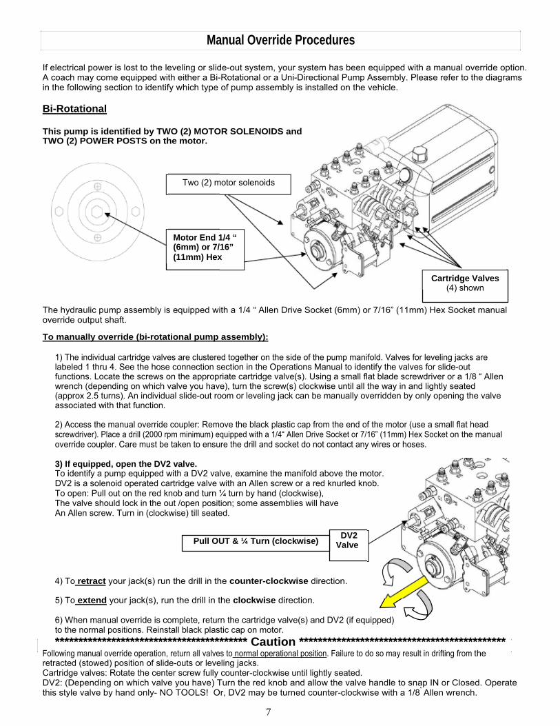
Bi-Rotational
This pump is identified by TWO (2) MOTOR SOLENOIDS and TWO (2) POWER POSTS on the motor.
Two (2) motor solenoids
Motor End 1/4 “ (6mm) or 7/16” (11mm) Hex
Cartridge Valves
(4) shown
The hydraulic pump assembly is equipped with a 1/4 “ Allen Drive Socket (6mm) or 7/16” (11mm) Hex Socket manual override output shaft.
To manually override (bi-rotational pump assembly):
1) The individual cartridge valves are clustered together on the side of the pump manifold. Valves for leveling jacks are labeled 1 thru 4. See the hose connection section in the Operations Manual to identify the valves for slide-out functions. Locate the screws on the appropriate cartridge valve(s). Using a small flat blade screwdriver or a 1/8 “ Allen wrench (depending on which valve you have), turn the screw(s) clockwise until all the way in and lightly seated (approx 2.5 turns). An individual slide-out room or leveling jack can be manually overridden by only opening the valve associated with that function. 2) Access the manual override coupler: Remove the black plastic cap from the end of the motor (use a small flat head screwdriver). Place a drill (2000 rpm minimum) equipped with a 1/4“ Allen Drive Socket or 7/16” (11mm) Hex Socket on the manual override coupler. Care must be taken to ensure the drill and socket do not contact any wires or hoses.
3) If equipped, open the DV2 valve. To identify a pump equipped with a DV2 valve, examine the manifold above the motor. DV2 is a solenoid operated cartridge valve with an Allen screw or a red knurled knob. To open: Pull out on the red knob and turn ¼ turn by hand (clockwise), The valve should lock in the out /open position; some assemblies will have An Allen screw. Turn in (clockwise) till seated.
Pull OUT & ¼ Turn (clockwise) DV2
Valve
4) To retract your jack(s) run the drill in the counter-clockwise direction. 5) To extend your jack(s), run the drill in the clockwise direction. 6) When manual override is complete, return the cartridge valve(s) and DV2 (if equipped) to the normal positions. Reinstall black plastic cap on motor. ***************************************** Caution ********************************************
Following manual override operation, return all valves to normal operational position. Failure to do so may result in drifting from the retracted (stowed) position of slide-outs or leveling jacks. Cartridge valves: Rotate the center screw fully counter-clockwise until lightly seated. DV2: (Depending on which valve you have) Turn the red knob and allow the valve handle to snap IN or Closed. Operate this style valve by hand only- NO TOOLS! Or, DV2 may be turned counter-clockwise with a 1/8” Allen wrench.
7
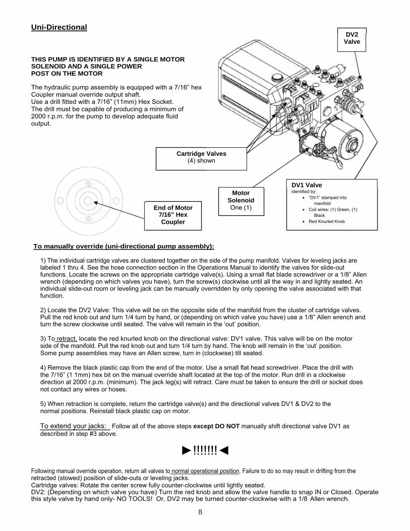
Uni-Directional DV2
Valve
THIS PUMP IS IDENTIFIED BY A SINGLE MOTOR SOLENOID AND A SINGLE POWER POST ON THE MOTOR
The hydraulic pump assembly is equipped with a 7/16” hex Coupler manual override output shaft. Use a drill fitted with a 7/16” (11mm) Hex Socket. The drill must be capable of producing a minimum of 2000 r.p.m. for the pump to develop adequate fluid output.
Cartridge Valves (4) shown
DV1 Valve
End of Motor 7/16” Hex Coupler
Motor Solenoid One (1)
Identified by: • “DV1” stamped into
manifold • Coil wires: (1) Green, (1)
Black • Red Knurled Knob
To manually override (uni-directional pump assembly):
1) The individual cartridge valves are clustered together on the side of the pump manifold. Valves for leveling jacks are labeled 1 thru 4. See the hose connection section in the Operations Manual to identify the valves for slide-out functions. Locate the screws on the appropriate cartridge valve(s). Using a small flat blade screwdriver or a 1/8” Allen wrench (depending on which valves you have), turn the screw(s) clockwise until all the way in and lightly seated. An individual slide-out room or leveling jack can be manually overridden by only opening the valve associated with that function. 2) Locate the DV2 Valve: This valve will be on the opposite side of the manifold from the cluster of cartridge valves. Pull the red knob out and turn 1/4 turn by hand, or (depending on which valve you have) use a 1/8” Allen wrench and turn the screw clockwise until seated. The valve will remain in the ‘out’ position. 3) To retract, locate the red knurled knob on the directional valve: DV1 valve. This valve will be on the motor side of the manifold. Pull the red knob out and turn 1/4 turn by hand. The knob will remain in the ‘out’ position. Some pump assemblies may have an Allen screw, turn in (clockwise) till seated. 4) Remove the black plastic cap from the end of the motor. Use a small flat head screwdriver. Place the drill with the 7/16” (1 1mm) hex bit on the manual override shaft located at the top of the motor. Run drill in a clockwise direction at 2000 r.p.m. (minimum). The jack leg(s) will retract. Care must be taken to ensure the drill or socket does not contact any wires or hoses. 5) When retraction is complete, return the cartridge valve(s) and the directional valves DV1 & DV2 to the normal positions. Reinstall black plastic cap on motor.
To extend your jacks: Follow all of the above steps except DO NOT manually shift directional valve DV1 as described in step #3 above.
►!!!!!!!◄
Following manual override operation, return all valves to normal operational position. Failure to do so may result in drifting from the retracted (stowed) position of slide-outs or leveling jacks. Cartridge valves: Rotate the center screw fully counter-clockwise until lightly seated. DV2: (Depending on which valve you have) Turn the red knob and allow the valve handle to snap IN or Closed. Operate this style valve by hand only- NO TOOLS! Or, DV2 may be turned counter-clockwise with a 1/8” Allen wrench.
8
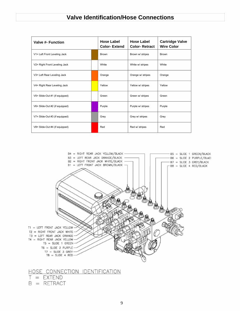
Valve #- Function Hose Label Color- Extend
Hose Label Color- Retract
Cartridge Valve Wire Color
V1= Left Front Leveling Jack Brown Brown w/ stripes Brown
V2= Right Front Leveling Jack White White w/ stripes White
V3= Left Rear Leveling Jack Orange Orange w/ stripes Orange
V4= Right Rear Leveling Jack Yellow Yellow w/ stripes Yellow
V5= Slide-Out #1 (if equipped) Green Green w/ stripes Green
V6= Slide-Out #2 (if equipped) Purple Purple w/ stripes Purple
V7= Slide-Out #3 (if equipped) Grey Grey w/ stripes Grey
V8= Slide-Out #4 (if equipped) Red Red w/ stripes Red
Valve Identification/Hose Connections
9
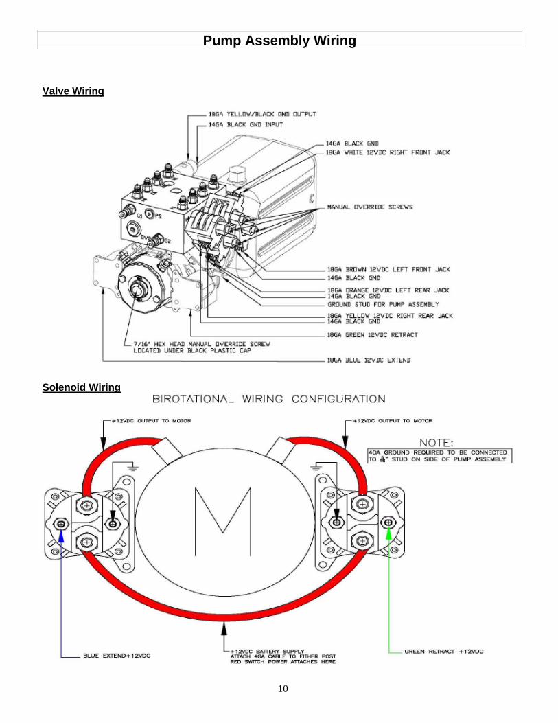
Pump Assembly Wiring
Valve Wiring
Solenoid Wiring
10
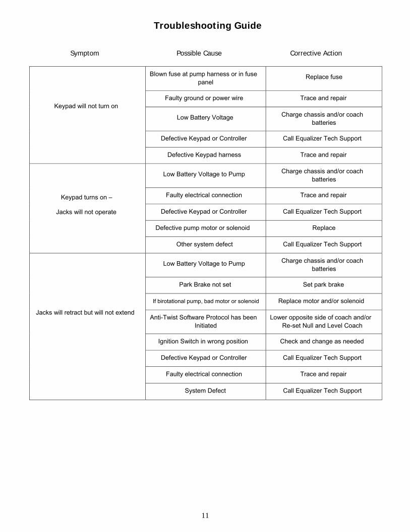
Keypad will not turn on
Blown fuse at pump harness or in fuse panel
Replace fuse
Faulty ground or power wire Trace and repair
Low Battery Voltage Charge chassis and/or coach batteries
Defective Keypad or Controller Call Equalizer Tech Support
Defective Keypad harness Trace and repair
Keypad turns on –
Jacks will not operate
Low Battery Voltage to Pump Charge chassis and/or coach batteries
Faulty electrical connection Trace and repair
Defective Keypad or Controller Call Equalizer Tech Support
Defective pump motor or solenoid Replace
Other system defect Call Equalizer Tech Support
Jacks will retract but will not extend
Low Battery Voltage to Pump Charge chassis and/or coach batteries
Park Brake not set Set park brake
If birotational pump, bad motor or solenoid Replace motor and/or solenoid
Anti-Twist Software Protocol has been Initiated
Lower opposite side of coach and/or Re-set Null and Level Coach
Ignition Switch in wrong position Check and change as needed
Defective Keypad or Controller Call Equalizer Tech Support
Faulty electrical connection Trace and repair
System Defect Call Equalizer Tech Support
Troubleshooting Guide
Symptom Possible Cause Corrective Action
11
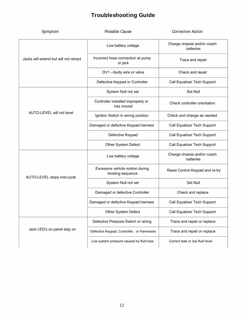
Jacks will extend but will not retract
Low battery voltage Charge chassis and/or coach batteries
Incorrect hose connection at pump or jack
Trace and repair
DV1 --faulty wire or valve Check and repair
Defective Keypad or Controller Call Equalizer Tech Support
AUTO-LEVEL will not level
System Null not set Set Null
Controller installed improperly or has moved
Check controller orientation
Ignition Switch in wrong position Check and change as needed
Damaged or defective Keypad harness Call Equalizer Tech Support
Defective Keypad Call Equalizer Tech Support
Other System Defect Call Equalizer Tech Support
AUTO-LEVEL stops mid-cycle
Low battery voltage Charge chassis and/or coach batteries
Excessive vehicle motion during leveling sequence
Reset Control Keypad and re-try
System Null not set Set Null
Damaged or defective Controller Check and replace
Damaged or defective Keypad harness Call Equalizer Tech Support
Other System Defect Call Equalizer Tech Support
Jack LED’s on panel stay on
Defective Pressure Switch or wiring Trace and repair or replace
Defective Keypad, Controller, or Harnesses Trace and repair or replace
Low system pressure caused by fluid loss Correct leak or low fluid level
Troubleshooting Guide
Symptom Possible Cause Corrective Action
12
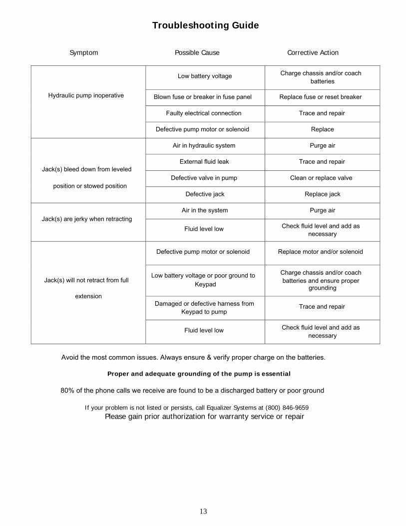
Hydraulic pump inoperative
Low battery voltage Charge chassis and/or coach batteries
Blown fuse or breaker in fuse panel Replace fuse or reset breaker
Faulty electrical connection Trace and repair
Defective pump motor or solenoid Replace
Jack(s) bleed down from leveled
position or stowed position
Air in hydraulic system Purge air
External fluid leak Trace and repair
Defective valve in pump Clean or replace valve
Defective jack Replace jack
Jack(s) are jerky when retracting Air in the system Purge air
Fluid level low Check fluid level and add as necessary
Jack(s) will not retract from full
extension
Defective pump motor or solenoid Replace motor and/or solenoid
Low battery voltage or poor ground to Keypad
Charge chassis and/or coach batteries and ensure proper
grounding
Damaged or defective harness from Keypad to pump
Trace and repair
Fluid level low Check fluid level and add as necessary
Troubleshooting Guide
Symptom Possible Cause Corrective Action
Avoid the most common issues. Always ensure & verify proper charge on the batteries.
Proper and adequate grounding of the pump is essential
80% of the phone calls we receive are found to be a discharged battery or poor ground
If your problem is not listed or persists, call Equalizer Systems at (800) 846-9659 Please gain prior authorization for warranty service or repair
13
Limited Warranty Policy
RV or Vehicle Manufacturer Installed Systems or Components: 1. Only warranty claims with prior written or verbal authorization from Equalizer Systems will be recognized, all other claims will be denied.
2. Equalizer Systems warrants slide out and leveling system components for a period of One Year from the date of original sale of the vehicle. This warranty covers defects in material and workmanship only. Equalizer Systems is not liable for any damage due to abuse, neglect, misuse, negligence, misapplication, error of operation, accidental or purposeful damage or damage due to an “act of God” such as, wind or rain damage, flood, lightning or other natural occurrence of the like. Equalizer Systems limited warranty is applicable to the Equalizer Systems components only and does not apply to the vehicle, apparatus or property to which it is attached. Warranty parts will be shipped at no charge if the repair is authorized by an Equalizer Systems representative. Purchased components used in authorized warranty repairs will be reimbursed at the original purchase price.
3. Labor and freight expenses due to warrantable parts defects or workmanship will be reimbursed for a period of one year from the date of original sale of the vehicle. Freight expenses will either be prepaid by Equalizer Systems or reimbursed at the UPS Ground rate only. Any additional shipping charges or requirements are the obligation of the vehicle owner or service center performing the warranty repair. The owner or service center’s obligation may include overseas shipping charges, border fees, brokerage fees and any other additional fee of the like.
4. Warranty labor will be reimbursed only for claims that have prior written or verbal authorization from an Equalizer Systems representative. Warranty labor compensation is required to correspond with the “Warranty Parts Replacement Time Guideline” published by Equalizer Systems. Any warranty repair not listed on this guideline will require prior authorization from an Equalizer Systems representative. A reasonable time allowance will be determined by the Equalizer Systems representative. Any warranty repair that is not listed on this guideline that is performed without prior authorization will be denied without exception. Time associated with learning about the repair or excessive diagnostic and installation time will not be reimbursed. Warranty labor will be reimbursed at the authorized service center’s published shop rate if the rate is reasonable for that region. Overtime labor will not be reimbursed without exception.
5. Labor, parts and freight credit (if applicable) will be sent after the parts are tested and the warranty claim is validated. Returned parts that are found to be in normal operating condition are not warrantable and will be charged to the owner or service center. Equalizer Systems reserves the right to charge back the service center for labor claim payments previously submitted if the installation of the warranted part is found to be inadequate at a later date.
6. Claims will be denied if the date submitted is greater than 30 days from the repair date.
7. Prior authorization is required before parts may be sent back to Equalizer Systems. A Return Authorization Number is required for items to be accepted.
8. Complete systems are not warranted unless authorized by an Equalizer Systems representative. There are absolutely no exceptions to this clause.
9. This warranty begins upon the original sale date of the vehicle and is transferable, with limitation, to subsequent owners upon furnishing the original sale date of the vehicle and proof of purchase. Only the remainder of the two year parts warranty is applicable. Warranty labor and freight are only applicable to original owner of the vehicle.
10. Equalizer Systems is not liable for loss of time, manufacturing costs, labor material, loss of profits, direct or indirect damages incurred by the vehicle manufacturer.
11. Excessive warranty labor resulting from inadequate access to the Equalizer Systems product will not be reimbursed.
12. Equalizer Systems will not pay a markup on warranty parts unless required by law.
13. Travel expenses, hotel, telephone, fuel or any other expenses of the like are not covered under warranty. Replacement Parts: 1. Replacement parts are warranted under the same guidelines listed above for the remainder of the original warranty or 90 days, whichever is longer. Proof of warranty repair date and original vehicle purchase date are required. No additional warranties, expressed or implied, are authorized by Equalizer Systems This warranty voids all previous issues. Questions concerning this warranty should be directed to:
Equalizer Systems 55169 CR 3 North Elkhart, IN 46515 1-(800) 846-9659 1-(574) 266-6083 fax
14


![img74.gkzhan.com · 10 -200 40 RB-057 30 RB-03 RB-023 RB-400 (kþZ) (m3/rnin) RB- 10 RB 152 4 6 7 (J 5 Ring BHower . Ring Blower + Air Filter Air the inlet model] and provide; tior](https://img.pdfslide.us/doc/110x75/601bc36bd8ed803f597f4be8/img74-10-200-40-rb-057-30-rb-03-rb-023-rb-400-kz-m3rnin-rb-10-rb-152-4.jpg)