Embed Size (px)
Citation preview
MODEL KHC INSTRUCTIONS
Contents
I. Standard Set 1
IT. Specifications .. ······· .. · .. ····· .... ·· .... ···· .. ·· .... ·· .. ··· .. · .. · .. ····· .. ·.... ·· .. ······ .. · 1
m. Name of Parts·················································································2
N. Optical Path.. ·· .... ·· .. ···· .... ·· ·· ···· .. ·.. · .. ·.. · .. ·· .. · ·· ·· ·.. ·· .. · · 2
V. Structure and Assembly .. ·· · · .. ·· ·3
VI. Method of Operation .. · · .. · · ·4
A. Smoothening of Coarse Adjustment knob
B. Light Source
C. Focusing
D. Interpupillary Distance and Diopter Adjustments
E. Use of Oil Immersion Objective
F. Use of Condenser
G. Change of Bulb
vll. Optical Characteristics 6
W. Major Troubles with Microscope, their Possible Causes
and Applicable Steps to be Taken ·.. ·.. ··7
IX. Important Points to Remember · .. ·8
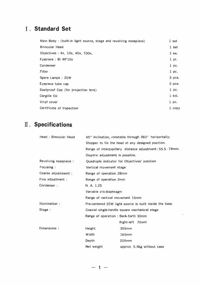
I. Standard Set
Main Body: (built-in light source, stage and revolving nosepiece)
Binocular Head
Objectives: 4x, lOx, 40x, lOOx,
Eyepiece ; Bi WFlOx
Condenser
Filter
Spare Lamps ; 20W
Eyepiece tube cap
Dustproof Cap (for projection lens)
Cargille Oil
Vinyl cover
Certificate of Inspection
IT. Specifications
1 set
1 set
lea.
1 pr.
1 pc.
1 pc.
3 pcs.
2 pce.
1 pc.
1 btl.
1 pc.
1 copy
Height
Width
Depth
Net weight
Head: Binocular Head
Revolving nosepiece :
Focusing:
Coarse abjustmemt :
Fine adjustment:
Condenser:
Illumination:
Stage:
Dimensions :
45 0 inclination, rotatable through 360 0 horizontally;
Stopper to fix the head at any designed position.
Range of interpupillary distance adjustment: 55.5 - 74mm.
Dioptric adjustment is possible.
Quadruple indicator for Objectives' position
Vertical movement stage
Range of operation 28mm
Range of operation 2mm
N. A. 1.25
Variable iris-diaphragm
Range of vertical movement 15mm
Pre-centered 20W light source is built inside the base.
Coaxial single-handle square mechanical stage
Range of operation: Back-forth 30mm
Right-left 70mm
355mm
165mm
205mm
approx. 5.5kg without case
-1-
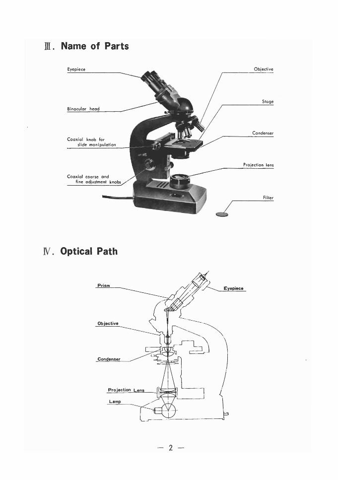
ill. Name of Parts
Eyepiece
Binocular head
Coaxial knob forslide monipulation
Coaxial coarse andfine adjustment knobs
N. Optical Path
Objective
Stage
Condenser
Projection lens
Filler
Prism
Projection Lens
Lamp
- 2 -
V. Structure and Assembly
A. Main Body
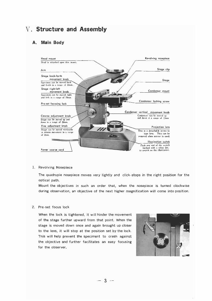
Head mount
Head i~ atta('hl~d upon this mount.
Arm
Slage back-forthmovement knob
Spl'('iml'n ca" be mO\'t"d backand forth in " rangll of 30mm.
Slage right-leftmovement knob
Sp('cimen can be mO\'cd ri..::hland l.. h in ,) ranlo1l' uf 70mm.
Pre-set focusing lock
Fine adjustment knob
StalCe can be moved \'erticaJlyin minute mo\'l'mcnt in il rangeof 2mm.
Power source cord
1. Revolving Nosepiece
Revolving nosepiece
Stage clip
Stage
Condenser mount
Condenser locking screw
Condenser vertical movement knobConden~er can hl' mon..J uvand down in a range of lSmm
Projection lens
This is a detachable screw-intype lens. This can be
remo\'cd when mirror is used.
Illumination switch
Push one end of the switchmarked with a white dOl.
to switch on the illuminator.
The quadruple nosepiece moves very lightly and click-stops in the right position for the
optical path.
Mount the objectives in such an order that, when the nosepiece is turned clockwise
during observation, an objective of the next higher magnification will come into position.
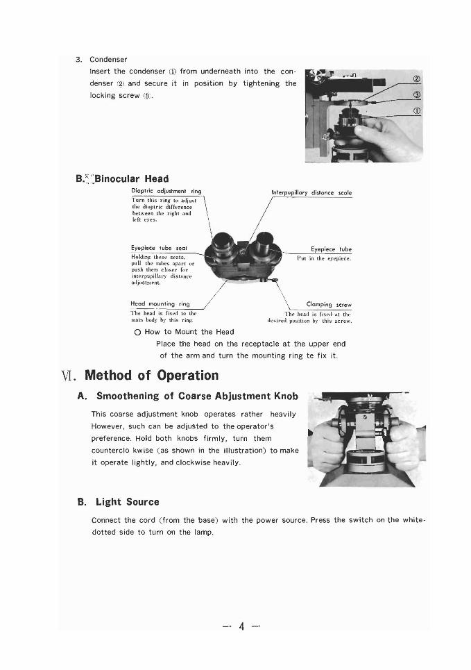
2. Pre-set focus lock
When the lock is tightened, it will hinder the movement
of the stage further upward from that point. When the
stage is moved down once and again brought up closer
to the lens, it will stop at the position set by the lock.
This will help prevent the speciment to crash against
the objective and further facilitates an easy focusing
for the observer.
3 -
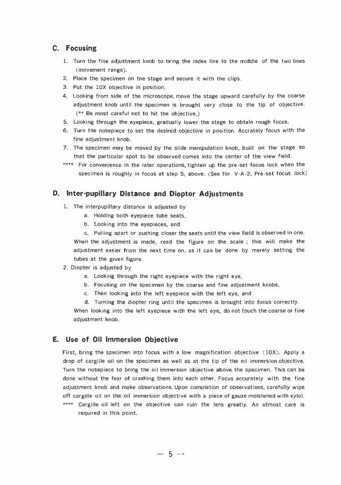
3. Condenser
Insert the condenser (1) from underneath into the con
denser (g) and secure it in position by tightening the
locking screw (3J.
B/';-':Binocular Head
CD
Dioptric adjustment ring
Turn this ring to adjustthe dioptric differencebetween the right andleft eyes.
Eyepiece tube seal
Holdin~ these seats,pull the lubes apart orpush them closer (orinterpupilbry distanceadjustmpnt.
Head mounting ring
Tht' head is £ixt.'d 10 th..main booy by thi~ ring.
Interpupillary dislance scale
/Eyepiece tube
Put in the eyepiece.
Clamping screw
Th~ head is fixed· at tll<'desired position by this screw.
o How to Mount the Head
Place the head on the receptacle at the upper end
of the arm and turn the mounting ring te fix it.
VI. Method of OperationA. Smoothening of Coarse Abjustment Knob
This coarse adjustment knob operates rather heavily
However. such can be adjusted to the operator's
preference. Hold both knobs firmly, turn them
counterclo kwise (as shown in the illustration) to make
it operate lightly, and clockwise heavily.
B. Light Source
Connect the cord (from the base) with the power source. Press the switch on the white
dotted side to turn on the lamp.
- 4 -
c. Focusing
1. Turn the fine adjustment knob to bring the index line to the middle of the two lines
(movement range).
2. Place the specimen on tne stage and secure it with the clips.
3. Put the lOX objective in position.
4. Looking from side of the microscope, move the stage upward carefully by the coarse
adjustment knob until the specimen is brought very close to the tip of objective.
(** Be most careful not to hit the objective.)
5. Looking through the eyepiece, gradually lower the stage to obtain rough focus.
6. Turn the nosepiece to set the desired objective in position. Accrately focus with the
fine adjustment knob.
7. The specimen may be moved by the slide manipulation knob, built on the stage so
that the particular spot to be observed comes into the center of the view field.
**** For convenience in the later operations, tighten up the pre-set focus lock when the
specimen is roughly in focus at step 5, above. (See for V -A-2, Pre-set focus lock)
D. Inter-pupillary Distance and Dioptor Adjustments
1. The interpupillary distance is adjusted by
a. Holding both eyepiece tube seats,
b. Looking into the eyepieces, and
c. Pulling apart or pushing closer the seats until the view field is observed in one.
When the adjustment is made, read the figure on the scale; this will make the
adjustment easier from the next time on, as it can be done by merely setting the
tUbes at the given figure.
2. Diopter is adjusted by
a. Looking through the right eyepiece with the right eye,
b. Focusing on the specimen by the coarse and fine adjustment knobs,
c. Then looking into the left eyepiece with the left eye, and
d. Turning the diopter ring until the specimen is brought into focus correctly.
When looking into the left eyepiece with the left eye, do not touch the coarse or fine
adjustment knob.
E. Use of Oil Immersion Objective
First, bring the specimen into focus with a low magnification objective (lOX). Apply a
drop of cargille oil on the specimen as well as at the tip of the oil immersion objective.
Turn the nosepiece to bring the oil immersion objective above the specimen. This can be
done without the fear of crashing them into each other. Focus accurately with the fine
adjustment knob and make observations. Upon completion of observations, carefully wipe
off cargille oil on the oil immersion objective with a piece of gauze moistened with xylol.
**** Cargille oil left on the objective can ruin the lens greatly. An utmost care is
required in this point.
-5-
F. Use of Condenser
If an objective of low magnification (less than 10X) is in use, lower the condenser
slightly to avoid an uneven illumination as well as for a better result. The upper-lens
of the condenser may be removed. Removal of the upper-lens gives a better result than
lowering of the condenser. When the oil-immersion objective is in use, move it up to
the top of its movement range.
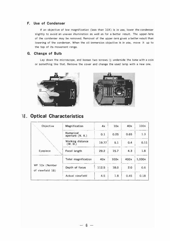
G. Change of Bulb
Lay down the microscope, and loosen two screws CD underside the base with a coin
or something like that. Remove the cover and change the used lamp with a new one.
vI. Optical Characteristics
Objective Magnification I 4x1
10x1
40x I 100x
"",". Numerical
I0.1
10.25 I 0.65
11.3
'" aperture (N. A.)
'" Working distance
I 19.771 I I", 5.1 0.4 0.11
"'"(W. D.)
Eyepiece "'. Focal length I 29.2 i 15.7 I 4.3 I 1.8
"" Total magnification I 40xI
100x I 400x 11'OOOX
WF 10x (NumberDepth of focus I 112.5 I 18.0 I 2.0 I 0.6
of viewfield 18)
I Actual viewfield I 4.5I
1.8 I 0.45 I 0.18
- 6 -
• * I} ;"'-"".A o.>Mt».l v ;...-;;( (.:: C;t f~)m;1J<A? ""C\.\.t To
"i'lli/, J; nJ·.If(1)j'f!f&J v ;..- ;< I.: Ij, 1!*1.1'A->c,':'l:i"o
:. tL Ij, ;t·Ht v ;..- ;< ,.: f,;;'J; ~ n C " .Q fcg··'t;
.W~~~<ct. ~(1)1!.~~ft~,m
$,IJ<fn'J' ~ J: ? I.: l&i&" Il;'j (1) fit! ~ ,it -> t.:. t(1) cei" 0
l&t&",iJlII.)-j"~I': i;i, g.,1i\'(1);jlt~jj~ L c1> I)
:'l: -ltA-1.I'. :FJi,\,'''j-ril~(1);1fJ I) ~1fi'~ AtL c
1> I) :'l: i" (1) c e, r.'flLl2.(1) 1-., ;(-it,.1Jl: Ri ffl L c
'I" ~ "0
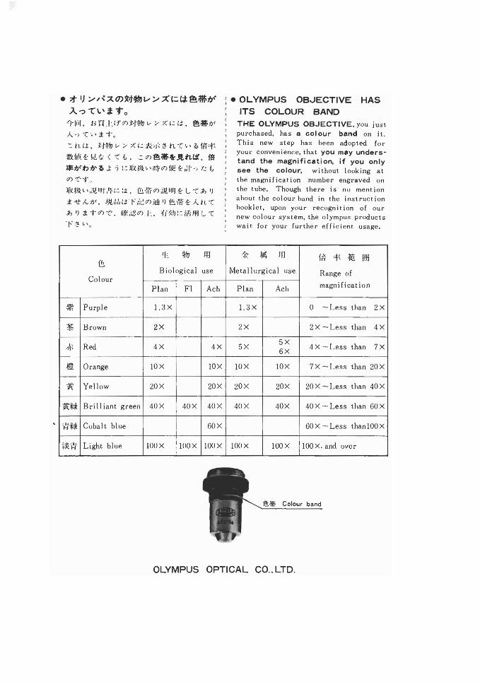
• OLYMPUS OB-JECTIVE HASITS COLOUR BAND
THE OLYMPUS OBJECTIVE, you justpurchased, has a colour band on it.This new step has been adopted foryour convenience, that you may understand the magnification, if you onlysee the colour, without looking atthe magni ficat ion number engraved onthe tube. Though there is no ment ionabout the colour band in the instructionbooklet, upon your recogni t ion of ournew colour system, the olympus productswait for your further efficient usage.
1= !/&J JfI /'I'i: ~ If] l-a' ,t; ~ lffi~
Biological use Metallurgical use Range ofColour
Plan Fl Ach Plan Ach magni ficat ion
~ Purple 1.3X 1.3X 0 -Less than 2X
~ Brown 2X 2X 2X -Less than 4X
,n; Red 4X 4X 5X5X
4 X -Less than 7X6X
.m Orange IOX IOX IOX IOX 7X -Less than 20X
1l. Yellow 20X 20X 20X 20X 20X -Less than 40X
'1t~ Brilliant green 40X 40X 40X 40X 40X 40X -Less than 60X
,~.f,1c Cobalt blue 60X 60X - Less thanlOOX
ik~j' Light blue lOO X lOO X lOO X lOO X lOO X lOOX. and over
is* Colour band
OLYMPUS OPTICAL CO.. LTD.
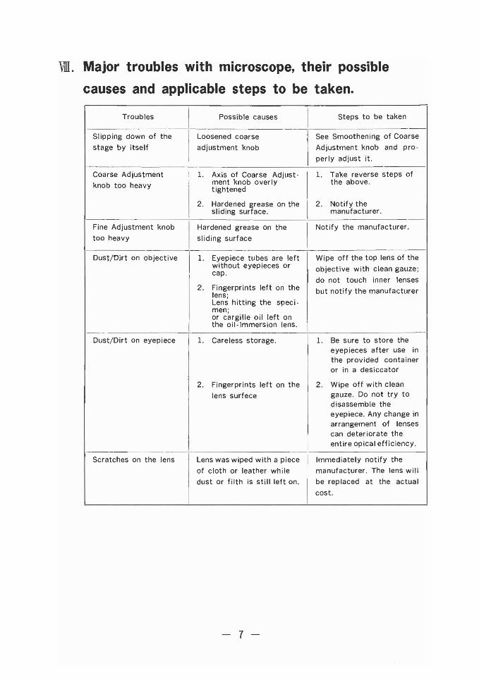
VIII. Major troubles with microscope, their possible
causes and applicable steps to be taken.
TroublesI
Possible causes1
Steps to be taken
Slipping down of the Loosened coarse See Smoothening of Coarse
stage by itself adjustment knob Adjustment knob and pro-
perly adjust it.
Coarse Adjustment 1. Axis of Coarse Adjust- 1. Take reverse steps of
knob too heavy ment knob overly the above.tightened
2. Hardened grease on the 2. Notify thesliding surface. manufacturer.
-Fine Adjustment knob Hardened grease on the Notify the manufacturer.
too heavy sliding surface
Dust/Oirt on objective 1. Eyepiece tubes are left Wipe off the top lens of thewithout eyepieces or objective with clean gauze;cap.
do not touch inner lenses2. Fingerprints left on the but notify the manufacturerlens;
Lens hitting the speci-men;or cargille oil left onthe oil-Immersion lens.
Dust/Dirt on eyepiece 1. Careless storage. 1. Be sure to store theeyepieces after use inthe provided containeror in a desiccator
2. Fingerprints left on the 2. Wipe off with clean
lens surfece gauze. Do not try todisassemble theeyepiece. Any change inarrangement of lensescan deteriorate theentire opical efficiency.
Scratches on the lens Lens was wiped with a piece Immediately notify the
of cloth or leather while manufacturer. The lens will
dust or filth is still left on. be replaced at the actual
cost.
- 7 -
IX. Important points to rememberDampness and dust is a taboo for the microscope. But, frequently, a lab where the
microscope is used is not free of such. It is the best to store microscope after each use in
the provided container. If frequent observations make it impossible, at least cover the
instrument with the provided vinyl cover.
The objectives and eyepieces should best be stored in a desiccator. Also recommended
is to place a pack of silicagel in the container. After the eyepiece is removed from the
instrument, be sure to cover the eyepiece tube with the provided cap. Never attempt to
disassemble or repair the mechanical parts of the microscope. It must be done by
specialists. Cleaning must be performed with utmost care. For expample, dust off with a
soft brush or blow off by a rubber ball where hands cannot reach.
Mirror (optional accessory)
In general, microscopy with KHC is conducted with the projection lens on. However, for
special illumination effect this mirror can be used for high magnification lens. and the other
side, concave surface, is good for observation with low magnification objl'ctives.
- 8 -


![Ana Paula Rocha - UPeol/TNE/APONT/Ontologies.pdf · Ana Paula Rocha Electronic Business Technologies TNE Motivation Battery ... [Uschold e Jasper, 1999] 5 TNE What is an ontology?](https://img.pdfslide.us/doc/110x75/5be6b4c809d3f23a518d4add/ana-paula-rocha-up-eoltneapont-ana-paula-rocha-electronic-business-technologies.jpg)