Embed Size (px)
Citation preview

DRAFT OKLAHOMA DEPARTMENT OF ENVIRONMENTAL QUALITY
AIR QUALITY DIVISION
MEMORANDUM August 26, 2010
TO: Phillip Fielder, P.E., Permits and Engineering Group Manager
THROUGH: Kendal Stegmann, Senior Environmental Manager, Compliance
and Enforcement
THROUGH: Phil Martin, P.E., Engineering Section
THROUGH: Peer Review
FROM: David Schutz, P.E., New Source Permits Section
SUBJECT: Evaluation of Permit Application No. 2007-005-C (M-13)
Refinery Integration and Mobile Source Air Toxics (MSAT-II) Project and
Related Projects
Holly Refining & Marketing (Formerly Sinclair Tulsa Refining Company)
Tulsa Refinery (SIC 2911)
902 W. 25th
Street, Tulsa, Tulsa County (36.126 N, 96.002 W)
Portions of Sections 13, 14 and 23, T19N, R12E
I. INTRODUCTION
Holly Refining & Marketing (HRMT) operates under Part 70 Permit No. 2007-005-TVR (M-11),
issued April 13, 2010.
HRMT has requested a construction permit for several projects which will be undertaken in close
time frames. The two most significant projects are (1) a project to integrate operations between
the former Sun Refinery (West Refinery) and former Sinclair Refinery (East Refinery) and (2) a
project to reduce the benzene content of gasoline.
The integration project primarily involves construction of pipelines between the two refineries‟
storage areas, but also involves expansion of two process units at the East Refinery to process
intermediates generated at the West Refinery along with those intermediates already produced at
the East Refinery. Other piping will allow hydrogen and fuel gas to be transferred between the
two refineries, activities which should reduce emissions by reducing one refinery‟s usage of
supplemental fuel or hydrogen-producing operations while the other refinery may be flaring
excess fuel or hydrogen

PERMIT MEMORANDUM NO. 2007-005-C (M-13) 2
DRAFT
EPA has promulgated requirements that gasoline contain lower benzene concentrations (40 CFR
Part 80). Lower benzene concentrations in gasoline grades produced at this refinery will be
accomplished by distilling a high-benzene product from the “reformate” (also known as
“platformate”), the product of a unit operated to convert naphtha into high octane aromatic
hydrocarbons, including benzene. HRMT intends to meet the new federal requirements by
construction of a “BenZap” unit. Although the unit will be constructed mostly from existing,
idled equipment, it will be treated as “new” for permitting purposes.
This permit will include three other related projects: Coker Blowdown upgrades and Flare Gas
Recovery (FGR) at the West refinery, and additional sulfur recovery for the East refinery (NaSH
(sodium hydrosulfide) unit installation).
Distillate Hydrotreating Unit: The existing Distillate Hydrotreating Unit (DHTU), a unit which
produces ultra-low-sulfur diesel and kerosene, will be expanded from the current capacity of
24,000 BPD to a capacity of 40,000 BPD. That unit includes a heater (ID “1H-101”) with a
maximum authorized firing rate of 55 MMBTUH. With the exception of replacing existing
burners with new low-NOx burners, the heater will not be physically modified. There will be
increased demand on the heater due to the increased processing capacity of the unit. This unit
consumes large amounts of hydrogen.
Continuous Catalytic Reforming Unit: The Continuous Catalytic Reforming Unit (CCR) will be
altered such that it can achieve its current design capacity of 22,000 BPD. This unit includes five
heaters, with maximum firing rates of 120, 101, 25, 85, and 141.8 MMBTUH. This unit produces
large amounts of hydrogen. Since the CCR Unit produces large amounts of hydrogen, additional
loading on other hydrogen-producing units will not result from the added demands for hydrogen
from expanding the DHTU.
There will be associated emissions increases from other units which are not physically modified.
There are four East Plant boilers which will be required to produce additional steam to support
the various units (primarily for heat for reboilers). The Naphtha Hydrodesulfurization Unit
(NHDS) is just upstream of the CCR, so increasing the flow through the CCR will require
increasing the processing rate at the NHDS. The NHDS Unit has two gas-fired heaters, a 39
MMBTUH charge heater and a 44.2 MMBTUH reboiler, whose operations will increase because
of the increased throughput. Increased throughput of diesel/kerosene through the DHTU (vapor
pressure 0.0076 at 68oF) will have a negligible increase in VOC emissions from tanks, but units
downstream of the CCR should see finite VOC emissions increases.
BenZap Unit: Feed for the BenZap Unit will be reformate from the East Refinery Continuous
Catalytic Reformer (CCR) and platformate from the West Refinery No. 2 Platformer Unit. The
feeds may be stored initially in Tanks 7 or 464 (both EFR tanks meeting Group 1 requirements
of 40 CFR Part 63, Subpart CC) or fed directly to a naphtha splitter (distillation unit) which will
produce a low-benzene content heavy reformate bottoms product and a high-benzene content
light reformate overhead product. The high-benzene content light reformate product will proceed
to a hydrogenation reactor where benzene is reacted with hydrogen to form cyclohexane. The
low-benzene content product from the hydrogenation reaction will be separated from unreacted
feed in the Stabilizer column. The reboiler for the stabilizer column is heated by refinery steam.

PERMIT MEMORANDUM NO. 2007-005-C (M-13) 3
DRAFT
Hydrogenated reformate will proceed to blending tanks where it will be mixed with the low-
benzene content heavy reformate bottoms product from the naphtha splitter or other gasoline
blendstocks.
Heat for the naphtha splitter will be supplied by heater 10H-105, a 75 MMBTUH unit.
Operation of the BenZap Splitter Heater is currently prohibited by a federal Consent Decree.
HRMT is in the process of requesting modifications to that CD. The unit will be equipped with
low-NOx burners upon start-up.
The refinery already produces a significant excess of hydrogen. No additional demand of boilers
and steam-reforming units is anticipated to supply hydrogen to the BenZap Unit. However, the
BenZap process will decrease the octane of light reformate, resulting in more demand on heaters
at the CCR to produce high octane aromatic gasoline blending components, and increased
demands on Cooling Tower No. 8. No increased emissions are expected from Cooling Tower
No. 8 since emissions are a function of circulation rate, which will not change.
The fugitive leakage components will be subject to NSPS Subpart GGGa. Emergency pressure
relief valves will be installed to vent the process to the refinery flares. However, given the
emergency nature of the relief valves, negligible changes in flare emissions are expected from
this connection. The flares could become subject to NSPS Subpart Ja upon connection of this
process or any other new process unit. A Federal Register publication on December 22, 2008,
stays “until further notice” the provisions of 60.100a(c); paragraph (c) states “For the purposes of
this subpart (Subpart Ja), a modification to a flare occurs if (1) any new piping from a refinery
process unit or fuel gas system is physically connected to a flare (e.g., for direct emergency
relief….” Since the provisions of (c) are the standards which would deem connecting the new
emergency relief valve to the flare to be a “modification,” and those provisions are stayed
indefinitely, the proposed connection of a relief valve to a flare is not a modification at this time.
It may be in the future, therefore, the permit will show potential applicability of NSPS, Subpart
Ja.
Sulfur Recovery / NaSH Unit: When completed, there will be three main portions to this project:
piping to send sweetened fuel gas to the West Refinery from the East Refinery, piping to send
sour fuel gas from the West Refinery to the East Refinery; putting an out-of-service amine
contactor (GV-1) back into service, along with installation of a new Amine Regeneration Unit
(ARU) No. 2, and a new NaSH (sodium hydrosulfide) unit. New fuel gas amine contactor GV-1
will be serviced with lean amine from the existing ARU #1. All other existing amine contactors,
with exception of the DHTU contactors, will continue to be supplied with lean amine from ARU
#1. The existing DHTU contactors will routinely be serviced by the new ARU #2. Each ARU
will be able to back up each other in case of a problem. Acid gas from the No. 2 ARU will go to
the NaSH Unit, then to the refinery Sulfur Recovery Units.
The new ARU No. 2 will require up to 18,000 lb/hr of steam from the existing boilers. Normal
steam demand will be somewhat lower.

PERMIT MEMORANDUM NO. 2007-005-C (M-13) 4
DRAFT
The NaSH unit will react sodium hydroxide (NaOH) with hydrogen sulfide (H2S) to form NaSH.
The product stream of the NaSH reactors will include 35-45% NaSH along with water and
unreacted sodium hydroxide. A new storage tank will be constructed to hold the outflow; since
the outflow is inorganic, the tank is not regulated by Air Quality rules or NSPS Subpart Kb. An
estimated maximum of 800 lb/hr steam will be used from existing boilers, most of which will be
needed in winter months.
Flare Gas Reduction Project: There are two primary sources of hydrocarbons in the flare gas
system, emergency releases and leakage. The Flare Gas Reduction recovers leakage by
compressing it into the existing sour refinery fuel gas header, which proceeds to the amine
contactors in the sulfur recovery area. This reduces the amount of supplemental natural gas
which the refinery needs to purchase by reducing the amount of waste gas flared.
Coker Blowdown Project: The Coker Blowdown currently vents to the West Refinery flare
system. Air coolers will condense water and some hydrocarbon vapors from this stream. The
liquids will be processed by the existing blowdown receiver, with the water fraction sent to plant
wastewater treatment and hydrocarbons being sent to existing slop oil storage.
The application utilizes NSR Reform allowances to determine emissions increases as Projected
Actual Emissions (PAE) minus Baseline Actual Emissions (BAE). Baseline actual emissions
were determined from the years 2008-2009 for NOx, CO, PM10, and VOC; for SO2, the years
2005-2006 were used. Future actual emissions will be lower than BAE for several units since air
pollution controls are required by a Consent Decree, controls including installation of qualifying
NOx controls on several combustion units, a flare gas recovery system, and a wet scrubber on the
FCCU. For those units where allowable emissions were later decreased by a federal Consent
Decree, the BAE were determined by multiplying the new allowable emissions by historical
process rates.
II. FACILITY DESCRIPTION
The East Refinery is a fuels refinery with several major process units. Other activities include
various minor processes outside the major units, including storage and transfer of products.
Much of the equipment is “grandfathered,” having been placed in service before the
promulgation of permitting requirements. The oldest construction dates from approximately
1907, when the Texas Company commenced building in the area. Sinclair purchased the facility
from Texaco in 1983, then Holly purchased the refinery in 2009. Refinery property covers
approximately 470 acres.

PERMIT MEMORANDUM NO. 2007-005-C (M-13) 5
DRAFT
Descriptions of each unit follow. Refining is a complex process to make crude oil into a variety
of products, including gasoline, heating oil, lubricants, and feedstocks for other industries.
Refining equipment and processes involve a certain amount of iterative treatment, in which
materials may be processed more than once at a particular location or may be returned to an
earlier step in the system for further handling. Only those processes necessary to understand the
basic principles are presented. A very general description of the entire process at this particular
refinery starts with crude oil being processed in the Crude Unit. Process streams flow from the
Crude Unit to the Fluid Catalytic Cracking Unit (FCCU), the Distillate Hydrotreating Unit
(DHTU), Naphtha Hydrodesulfurization Unit (NHDS), and the Unifiner/Penex (Penex). A
residual stream becomes asphalt or residual fuel oil. Tulsa Refinery final products are classified
as gasoline, distillate, residual fuel oil, and asphalt, but there are also intermediate products, such
as propane, butane, propylene, and sulfur.
Note that Emission Unit Groups (EUGs) are based on different criteria from those used to
describe process units, so descriptions of the EUGs do not match those of the processing units.
For example, EUG #9 consists of heaters found in three different units. Similarly, although the
bulk of all tanks is found in the Product Blending Unit, the storage tanks are divided into EUGs
based on roof design and permit status. Since the initial TV permit was issued in 2002, some
emission units (EUs) have been moved between EUGs and some of the EUGs have been
renamed.
A. Crude Distillation Unit (CDU)
Distillation is a thermal process that separates product fractions out of a mix of materials based
on differences in boiling points. The CDU separates crude oil into intermediate products, which
are either feedstocks for downstream units or residual products. Sour crude, defined by HRMT
as crude oil with sulfur content greater than 0.5% by weight, represents approximately 10% of all
volume processed by this unit. The remaining 90% sweet crude at the Tulsa refinery has
historically averaged approximately 0.4% by weight sulfur. Sour crude is usually run through
the CDU at approximately 55,000 barrels per day (BPD) and sweet generally run at
approximately 65,000 BPD. The CDU does not have a stated design capacity, because the unit
was designed and constructed at a time when refinery design was more of an art than a science.
Hydraulic capacity of the refinery may exceed 80,000 BPD, but efficiency and product quality
are more critical limiting conditions. A detailed physical analysis of the facility for the express
purpose of determining theoretical capacity has never been performed and may not be feasible.
Minor piping/equipment modifications and use of “waste” heat can marginally improve
performance, efficiency, and throughput capacity. The best sustainable throughput of 75,000
BPD of sweet crude over a period of 24 days was set in July 2004.
Crude oil is currently brought to the refinery through Enbridge and Sun pipelines. Deliveries are
metered, sampled, and tested before processing. Sweet and sour crude are segregated in storage
tanks and are processed in separate batches through the CDU. All crude is de-salted before
entering the distillation towers to remove chlorides that would be damaging to piping and
vessels. Sweet crude is occasionally injected into sour crude runs. There are fugitive emissions
from the CDU. The only point source is a common stack serving two heaters. These gas-fired
heaters serve the atmospheric distillation tower and the vacuum distillation tower (EUG 9, Point
ID 6155). Crude flows through the atmospheric tower first, where the lighter ends are removed

PERMIT MEMORANDUM NO. 2007-005-C (M-13) 6
DRAFT
or distilled. “Atmospheric” simply refers to the fact that the constituents distilled in the tower
are capable of vaporizing at atmospheric pressure. Heavier ends that are not distilled in this
tower are then run through the vacuum tower for further separation. A vacuum is achieved in the
vacuum tower through use of three stages of steam ejectors. Condensers remove condensable
vapors to the greatest extent possible after each of the ejectors. The vent gas flows to the wet gas
compressor (J-50) within the FCCU. More information about this stream is found in Section B,
following. This vent gas was previously directed to the heater flame zone, and this bypass option
has been retained for use in the event that the FCCU or J-50 go out of service. Some material is
refluxed, meaning that it is taken out of the column and reintroduced at an earlier point to
achieve better separation into distinct product fractions. Refluxing is also a method for taking
heat out of the tower. It is one of the processes that is used at different points and that constitutes
one of the previously mentioned techniques to improve performance and more efficiently process
materials in the CDU.
HRMT defines eight outputs from the CDU in order of increasing molecular weight as follows.
Numbers 1 - 6 come from the atmospheric tower, while 7 and 8 come from the vacuum tower.
1. Light ends. This stream is methane and ethane and goes to the FCCU.
2. Butane/propane. This stream goes to the DHTU or FCCU.
3. Light straight run. This is mostly C5 material and goes to Penex.
4. Naphtha. This material goes to the NHDS.
5. Kerosene. This goes to the DHTU.
6. Light atmospheric gas oil. This goes to the DHTU.
7. Gas oils. These go to the FCCU.
8. Vacuum resid. This is the residual material or “bottoms” remaining after all other
outputs have been captured. Resid goes directly for sale as asphalt or roofing flux. There
are no asphalt blowstills or other oxidation processes utilized at the Tulsa Refinery. The
facility refers to the sour bottoms as asphalt and to all other material as “flux.”
Intermediate storage for both materials is in heated tanks.
The CDU is also responsible for managing butane truck loading and unloading (EUG 15, EU 22,
Point ID 6171).
B. Fluid Catalytic Cracking Unit (FCCU) The FCCU treats gas oils from the CDU (hot) or gas oils from storage (cold) with heat in the
presence of a catalyst. Generally, hot gas oil from sweet crudes is mixed with cold gas oil from
sour crudes, and the situation is reversed when sour crude is being processed. The FCCU has
current capacity estimated at 24,000 BPD and usually processes approximately 20,000 BPD.
“Gas oils” are heavier than diesel and lighter than the residual products taken from the CDU.
Heavy molecules are broken or “cracked” into lighter molecules that allow the facility to
increase the production of liquid fuels. A distillation tower then separates these products into
gasoline and diesel components, as well as producing feedstock for the Alkylation (ALKY) and
Scanfiner (SCAN) Units.

PERMIT MEMORANDUM NO. 2007-005-C (M-13) 7
DRAFT
FCCU catalyst is regenerated continuously to prevent coke build-up, with sufficient catalyst
added daily to maintain a relatively constant inventory and level of catalytic activity. Spent
catalyst is removed from the regenerator every few days and stored for sale to other refiners or
catalyst brokers. This catalyst is valuable and various devices control potential air emissions of
it, to minimize its loss. The first set of these devices consists of cyclones in the reaction vessel.
In addition, the regenerator contains five three-stage cyclones. The electrostatic precipitator
(ESP) on the FCCU stack has been replaced by a wet gas scrubber (WGS). Salts and particulates
removed by the WGS are shipped offsite for disposal, while the liquid will be sent to the oily
wastewater collection system. A selective catalytic reduction (SCR) system has been added to
control NOX emissions. Installation of the SCR required the addition of a 20,000-gallon tank for
aqueous ammonia and two 6,400-gallon tanks for sodium hydroxide. The aqueous ammonia is
an ammonium hydroxide solution with less than 20% concentration of ammonia. Carbon
monoxide emissions from the regenerator are minimized through complete combustion by
controlling the excess oxygen content in the flue gas. The FCCU is very difficult to shut down
and start up due to the high temperatures involved and the volume of catalyst circulating through
it. These activities are managed and tracked through the facility‟s startup, shutdown, and
malfunction plan (SSMP). Control devices will be discussed in EUG 11 of Section III
(Equipment) below.
Similar to the handling of crude in the CDU, products of this cracking process are distilled
thermally in the tower. Heavy ends, or tower “bottoms,” are known as decanted oil and may be
used for fuel at the Boiler House. Light ends from this unit and gasses from the CDU are
compressed and run through an absorber at the FCCU. Any remaining gas becomes part of the
refinery fuel gas system. A set of natural gas-fired compressors was formerly used to compress
and circulate the unit gas for further processing. This set of compressors was taken out of
service and replaced by an electrically driven compressor (J-50). This compressor is often called
the “wet gas compressor.”
A gas-fired charge heater (B-2) supplies heat for current operation of the FCCU. A gas-fired
reboiler heater (B-4) sharing the charge heater stack has been idle since 1992. Heat to perform
the function of this reboiler is now taken from the fractionator slurry bottoms. A gas-fired air
heater (B-1) is used only during FCCU startup. A gas-fired steam superheater has been idle
since 1996. Heat previously supplied by the superheater is now obtained from B-2.
Propylene loading of railcars (3-spot) and trucks (1-spot) is functionally connected to the FCCU.
Additionally, the FCCU is responsible for the operation of two flares, all pressurized spheres,
and all pressurized “bullet” tanks except for three tanks located at the ALKY Unit. The CDU,
FCCU, ALKY, POLY, and PENEX Units feed flare #1. Everything else is directed to flare #2.

PERMIT MEMORANDUM NO. 2007-005-C (M-13) 8
DRAFT
C. Unifiner/Penex Unit (PENEX)
PENEX is a process that was installed at the ISOM (Isomerization) Unit in 2002. The PENEX
upgrades the octane of light straight run naphtha from the CDU by isomerizing the normal
pentanes to isopentanes. The PENEX also saturates benzene, thus reducing the benzene and
aromatic levels in gasoline produced by HRMT. Light straight run naphtha from the CDU is
sent to intermediate storage before it is charged to the PENEX. PENEX contains two reactors
that can be operated in any order. Catalyst in these reactors has an optimal life of seven years
and is reclaimed, but not regenerated. The charge is first treated by the Unifiner reactor to
remove sulfur and nitrogen. This is a catalytic process that requires hydrogen from the CCR (see
below) to combine with the elemental sulfur stripped out of various compounds, such as
mercaptans. The hydrogen sulfide thus formed can be stripped out of the stream and sent for
processing at the SRU (see below). Unifiner catalyst is long-lived and normally does not require
regeneration.
Products from the PENEX are normally sent to intermediate storage as gasoline blending
components but can also be blended directly into gasoline. Offgas produced is run through an
absorption process before being sent to the fuel gas system. The absorber is light cycle oil from
the FCCU. Heavier constituents of the offgas are absorbed by the oil and sent to the FCCU
fractionator, while the lighter ends are used as fuel gas. The ISOM was commissioned in 1987
by modifying a catalytic reforming unit (CRU) that had been idle for a long period.
The Unifiner section has a charge heater and stack (EUG 9, Point ID 6167. The normal charge
rate to the PENEX is approximately 6,000 BPD although it has nominal capacity to charge over
8,500 BPD.
D. Continuous Catalytic Reforming Unit (CCR)
The CCR upgrades the octane of heavy straight run naphtha from the CDU (through the NHDS)
by dehydrogenating the hydrocarbons, resulting in the production of high octane materials such
as aromatics. These high octane “blend stocks” are blended directly into gasoline. This stream
is one of the most important components of premium grades of gasoline. HRMT‟s reforming
process is also called platforming, because it uses a platinum catalyst in three reactors. The
catalyst is fouled quickly by sulfur, so only sweet naphtha feedstock from the NHDS may be
used. This process had been performed by the catalytic reforming unit (CRU), which was
modified under Permit No. 98-021-C (M-26) to create the CCR. The CRU required a complete
unit turnaround to regenerate the catalyst. The existing unit was converted into a CCR capable
of processing approximately 22,000 BPD of desulfurized naphtha from the NHDS. Three new
reactors hold approximately 100 tons of catalyst and circulate 1,000 pounds of catalyst through
the regenerator per hour. Catalyst flows down through each reactor, dropping from each reactor
to the next. As the catalyst exits the bottom of the third reactor, a countercurrent flow of
hydrogen purges hydrocarbon back into the third reactor. Nitrogen then carries the catalyst to
filter media at the top of the regenerator structure, where fines are removed from the catalyst
before it flows to a disengaging hopper.
PERMIT MEMORANDUM NO. 2007-005-C (M-13) 9
DRAFT
The “disengaging” term used here means that this is the point at which the catalyst is no longer
borne by the nitrogen; it is “disengaged” or separated from the nitrogen transportation medium.
Approximately 5-10 pounds of fines are expected to be removed daily and sent for offsite
reclamation. The catalyst is cooled to 250-300 F in the disengaging hopper, and is then dropped
into the regenerator. The regenerator has three zones, identified as the diluted air zone, the
oxychlorination zone, and the drying zone. Approximately 0.07 mol% oxygen is reacted with
the catalyst to begin coke burn-off in the diluted air zone. The low oxygen content and the name
of the zone are derived from diluting air with nitrogen. The catalyst then drops to the
oxychlorination zone, where it is reacted with air and perchloroethylene (perc), which conditions
the catalyst by redistributing the metal on the catalyst. Air is blown across the catalyst in the
drying zone to remove any remaining moisture. The regenerated catalyst exits the bottom of the
regenerator and is moved with hydrogen to the reduction zone above the top of the first reactor.
At this point it is further regenerated by contact with additional hydrogen, which combines with
excess oxygen to create water vapor. During reactor operation, chloride is injected into the
reactor to help maintain catalyst activity. The regenerator tower vents back through the
disengaging hopper, allowing the sulfur and chloride in the regenerator vent gas to be absorbed
by the catalyst entering the regenerator. This reabsorption process is known as Chlorisorb.
Platforming produces hydrogen that is then used by the NHDS, DHTU, SCAN, and PENEX
units for desulfurization of their feedstocks, although some of the hydrogen is retained or
recycled in the reactors to prevent the reaction from cracking the naphtha. The CCR had first
operations on December 11, 2007.
There are five heaters associated with this unit. A 141.8 MMBTUH heater, identified as the #1
Interheater (10H-113), is described in EUG 26. One stack serves the 101 MMBTUH Interheater
#2-1, the 25 MMBTUH Interheater #2-2, and the 120 MMBTUH charge heater, and is identified
as Point ID 6163 in EUG 27. The 85 MMBTUH stabilizer reboiler heater is identified as Point
ID 6162 of EUG 27. The newer 141.8 MMBTUH heater was installed with low-NOX burners
and the 120 and 85 MMBTUH heaters have been retrofitted with low-NOX equipment.
E. Naphtha Hydrodesulfurizer Unit (NHDS)
The NHDS removes sulfur from the CCR charge (heavy straight run naphtha), with a capacity of
22,000 BPD. The sulfur removal process is catalytic and requires hydrogen, which is supplied
by the CCR. The interdependence of this Unit and the CCR requires that sufficient sweet
material produced by the NHDS be stored to provide for a startup of the CCR. Sulfur is removed
in the form of H2S. Most of the offgas from this unit is recycled, with excess gas being amine-
treated before going to the fuel gas system. Hydrogen is injected in several places and a large
part of the unit has two-phase flow. Some of the hydrogen passes through the system and is
being continually recovered, compressed, and recycled. The NHDS is normally shutdown every
three to four years for maintenance, based on catalyst life. The catalyst is not normally
regenerated and is replaced every few years. Spent catalyst is sent off site for either regeneration
or metals reclamation and disposal. This unit had first operations on March 20, 2006.
There are two heaters with low-NOX burners at this unit. A 39 MMBTUH charge heater and a
44.2 MMBTUH stripper reboiler heater are both described in EUG 25.

PERMIT MEMORANDUM NO. 2007-005-C (M-13) 10
DRAFT
F. Distillate Hydrotreating Unit (DHTU)
The old naphtha/distillate HTU was converted to a DHTU capable of processing approximately
24,000 barrels per day (BPD) in 2006. Conversion included new internals in the reactor, such as
reducing the number of catalyst beds, using a new catalyst, and redesigning the quench nozzles.
There are several new vessels, including a high pressure separator, a new amine treater, a
coalescer, a salt tower, and various air and water coolers. The existing HTU charge heater
remains in service as the DHTU charge heater, but the stripper reboiler heater was permanently
removed in 2006. First operations at the DHTU occurred May 25, 2006.
The DHTU removes sulfur from diesel blend stocks. Both #1 and #2 diesel streams are treated
in the DHTU. Naphtha is treated by the NHDS (see E above). The DHTU normally treats
approximately 24,000 BPD of distillate streams from the field or hot from the CDU or the
FCCU. Gases from this Unit are treated before going to the fuel gas system. The DHTU is
normally shutdown every three to four years for maintenance, based on catalyst life. The
catalyst is not normally regenerated and is replaced every few years. The catalyst is sent off site
for either regeneration or metals reclamation and disposal. The DHTU is dependent on the CCR
for hydrogen. The DHTU is also responsible for the Light Hydrocarbon Treating Unit (LHC)
which treats light hydrocarbon streams to remove hydrogen sulfide.
There are two emission points associated with this unit; one active and one inactive. The charge
heater stack is Point 6157 in EUG 27. The other stack is Point ID 6156 (was in EUG 9) common
for both the splitter and fractionator reboiler heaters, both of which were idled as part of the
conversion of the old HTU to the DHTU.
G. Alkylation Unit (ALKY)
Alkylation is a process that creates large molecules by reacting two shorter molecules in the
presence of a catalyst. In this case, the alkylate produced is typically high-octane material
necessary for blend stock. Debutanizer net overhead from the FCCU is rich in butenes and
serves as ALKY feedstock. The feed is pre-treated by the POLY. Treated feed first passes
through a deethanizer. Light ends are sent to the fuel gas system and the feed is sent to the
propylene splitter at the POLY unit, as described in H below. The remaining olefin feed,
consisting mostly of butenes, is returned to ALKY to be reacted with isobutanes using sulfuric
acid as a catalyst to produce the alkylate. The process uses isobutanes greatly in excess of the
stoichiometric amount, so the alkylate is fed through three more towers, those being the
depropanizer, deisobutanizer and debutanizer. Historically, approximately 3,500 BPD of
alkylate has been produced. The facility accepted a limit of 5,500 BPD to avoid PSD
consideration under Permit No. 98-021-C, issued October 18, 2000. The ALKY receives
sulfuric acid and stores it for use. It also sends spent acid for regeneration. Sulfuric acid is
loaded from and unloaded to trailers at the ALKY, and can also be received from and loaded into
rail cars. The ALKY is also responsible for three pressurized bullet tanks, Nos. 58, 59, and 60,
located on the unit (EUG 22, Point ID 6288 through 6290). One of these tanks holds butane, a
second holds isobutane, and the third is a surge tank used for emergency service. Isobutane is
purchased, because insufficient supplies are generated at the refinery and there is no Butamer
unit at the refinery to convert butane to isobutane. There are no point sources associated with
this unit.

PERMIT MEMORANDUM NO. 2007-005-C (M-13) 11
DRAFT
H. Poly Pretreat Unit (POLY)
This area of the refinery was originally a polymerization unit, hence the name POLY. Most of
the unit has been idle since some time prior to HRMT‟s purchase of the refinery, but some pieces
of equipment have been used for other purposes. Feed for the ALKY unit is treated by the
POLY to remove sulfur and any other impurities that might harm the catalyst or otherwise
disturb the reaction. An amine system removes hydrogen sulfide, caustic solution removes
residual hydrogen sulfide and mercaptan sulfur, and a water wash removes basic nitrogen
compounds. A propene recovery system, often referred to as the propylene splitter, was started
at the POLY unit in 1996. Approximately 600 BPD of propene have been recovered, stored, and
sold as a product in the past. POLY is estimated to have average capacity of 4,000 BPD. There
are no point sources associated with this unit.
I. Scanfiner (SCAN)
The SCAN process takes all or a portion of naphtha (often referred to as „cat naphtha‟ or „cat
gasoline‟) from the fluid catalytic cracking unit (FCCU) and removes the sulfur. The first stage
of the process, the diolefin saturator, is designed to convert diolefins into olefins without
beginning hydrodesulfurization or olefin saturation. Diolefins need to be removed as they can
cause significant fouling in the process equipment.
After diolefin saturation, the cat naphtha is fed into the main SCAN reactor, where
hydrodesulfurization, hydrodenitrogenation, and olefin saturation reactions occur over a catalyst.
The main product from this reactor is low sulfur cat naphtha, which is a key blend component in
producing low sulfur gasoline blends. The process consumes hydrogen and also recovers
hydrogen, hydrogen sulfide, and ammonia. The product stream is cooled and water washed prior
to entering the reactor effluent separator. Water wash helps prevent chloride build-up in the
equipment, and the water is reused to the greatest extent possible through the system. A minimal
amount of water is sent to the refinery wastewater system to maintain wash water quality. The
hydrogen from the reactor effluent separator, called recycle gas, is sent to an amine absorber in
the SCAN unit where the hydrogen sulfide is removed. A small portion of the recycle gas is
purged to the fuel gas system to maintain adequate hydrogen purity and makeup hydrogen is fed
into the recycle gas upstream of the amine absorber. The recycle gas is then compressed and
sent back to the reactor section. Liquid hydrocarbon from the separator is sent to the product
stripper, where light ends (butane and higher) and hydrogen sulfide are removed. The non-
condensable gas stream (hydrogen, hydrogen sulfide, ammonia) from the separator is sent to an
existing amine absorber where it is amine scrubbed for hydrogen sulfide removal prior to
injection into the fuel gas system. Low sulfur gasoline from the product stripper is sent to
gasoline blending after cooling. ARU #1 processes the sour amine solution from the amine
absorber. Acid gas from the ARU is vented to the sulfur recovery units (SRU#1 and/or SRU#2).
The hydrogen utilized in the SCAN process is obtained from the excess hydrogen produced by
other process equipment. This hydrogen is blended into the refinery fuel gas system and used to
fire the various process heaters and boilers at the refinery. While the SCAN process generates a
small quantity of fuel gas, any additional fuel gas demand at the refinery created by removal of
the hydrogen from the fuel gas system is satisfied by purchasing natural gas. First operations of
the Scanfiner unit occurred December 17, 2004.

PERMIT MEMORANDUM NO. 2007-005-C (M-13) 12
DRAFT
J. Sulfur Recovery Units (SRU #1/ SRU #2)
The SRUs recover sulfur from acid gas streams and sour water stripper overhead and store it in
elemental form for sale. The refinery currently has an amine system that removes H2S from
various gas and liquid hydrocarbon streams. There are six amine treaters (or “contactors”) that
contact the different streams with lean amine, where “lean” means that the amine has a low
concentration of H2S. The lean amine absorbs the H2S, making it into a “rich,” or high-
concentration, stream. The ARU regenerates the amine solution by boiling it, producing lean
amine to return to the contactors and hydrogen sulfide to feed the SRU. The SRUs use the Claus
process. One third of the H2S is oxidized to form SO2 and the SO2 is reacted with the remaining
H2S in the presence of an alumina catalyst to form elemental sulfur and water vapor. The liquid
sulfur is stored in a pit for shipping by rail or truck. The reaction does not achieve total removal
of sulfur (with an approximate 95% efficiency), so the tail gas is scrubbed by Tail Gas Treating
Units (TGTU) to recover any remaining sulfur oxides formed before they are released from the
stack (EUG 10, Point ID 6152). These units incinerate remaining H2S to SO2, which is then
removed by a following caustic scrubber. Scrubber products are routed to the wastewater
treatment system. Tail gas concentration of SO2 is maintained below 250 ppm. Continuous
emission monitors (CEMs) on both SRUs demonstrate compliance. SRU #2 had first operation
on June 1, 2006.
The Sour Water Stripper (SWS) is also associated with this complex of units. The SWS takes
sour water from various units and removes ammonia and H2S. Modifications to the SWS in
2006 replaced the trays, increased the operating pressure of the stripper, and installed a new
feed-to-bottoms heat exchanger. These changes increased the capacity to approximately 190
gpm. Offgas from SWS is sent to SRU #2, because SRU #1 has proven incapable of handling
this material without fouling of the catalyst. If SRU #2 is unavailable for some reason, SWS will
be placed on fresh water feed or shut down and sour water stored in tanks. Upon return to
service of SRU #2, any accumulated sour water will be processed and the offgas sent to SRU #2.
The design capacities of SRU #1 and SRU #2 are each 25 long tons per day (LTPD).
K. Product Blending (PB)
Product Blending is responsible for tankage at HRMT. The majority of the tanks are fixed roof
tanks storing materials of low volatility. More volatile material is stored in floating roof tanks or
pressure vessels such as bullet tanks for propane and propene and spheres for butane. The PB
department receives crude oil and ships out gasoline and diesel products by pipeline. The PB
department is also responsible for the wastewater treatment facility (EUG 17, Point ID 13409)
and the asphalt loading racks. Asphalt and flux are loaded out by truck (EUG 14, Point ID 6170)
and by railcar (EUG 14, Point ID 6169). There is also a diesel railcar loading rack (EUG 14,
Point ID 14455) and a gas oil truck loading rack (EUG 14, Point ID idle). Two external floating
roof tanks for storage of off-test wastewater are relatively new sources also under PB control.
These tanks are Point IDs 15940 and 15941 in EUG 20.

PERMIT MEMORANDUM NO. 2007-005-C (M-13) 13
DRAFT
L. Boiler House (BOHO)
The BOHO is responsible for steam production for the refinery. The BOHO is also responsible
for the other utility systems such as plant air, instrument air, and nitrogen. There are four boilers
at the BOHO, each capable of producing over 100,000 pounds per hour of 250 psig steam.
These boilers primarily burn sweet plant fuel gas, but each is also capable of burning liquid fuel,
which occurs only during gas curtailment, operator training, or burner testing. Generally, a
different boiler is shut down every six months for maintenance. Under the original design,
boilers 1 and 2 shared a common stack and boilers 3 and 4 shared another common stack. The
CD requires that each boiler have its own stack and that each boiler be subject to NOX control.
Because the facility decided to install a more efficient form of control than originally outlined in
the CD, the compliance date was shifted to December 31, 2009. Now there are selective
catalytic reduction (SCR) systems on all four boilers. Continuous emission monitoring systems
(CEMS) have been or will be installed on each stack, although the first compliance
demonstration is not required until June 29, 2010 or 180 days after first operation of each
individual SCR, whichever date occurs first. These are the only emission points associated with
the BOHO.
M. Sales Terminal
The sales terminal is responsible for the shipment of gasoline, diesel, and propane via tank
trucks. All of the propane produced and stored at the refinery is shipped out from the terminal.
The sales terminal ships much of the gasoline and some of the diesel produced in the refinery.
The gasoline and diesel are loaded from a four-bay, bottom-fill loading rack that is controlled by
a thermal oxidizer (EUG 15, Point ID 6275). An automatic interlock device shuts down the
loading operation if the combustor malfunctions. All pumps are powered by electricity. Under
ideal conditions, these pumps are capable of pumping a combined total of 9,000 gallons per
minute, but this rate is not sustainable for long periods. The propane truck loading rack
constructed in 1951 is on vapor balance with the propane tanks or fuel gas system at the refinery.
Crude oil enters the refinery at a metering station located at the terminal.
N. Wastewater Treatment Plant (WWTP)
The Wastewater Treatment System collects and treats wastewater generated in the refinery prior
to discharging water to the Arkansas River, including both process generated wastewater and
storm water. Both federal and state agencies regulate the effluent going to the river. Federal
requirements are under the jurisdiction of the Environmental Protection Agency (EPA) and are
covered by the National Pollutant Discharge Elimination System (NPDES). State requirements
are under the jurisdiction of the Oklahoma Department of Environmental Quality (ODEQ) and
are covered by the Oklahoma State Discharge Permit System (OSDPS). Various federal
standards govern wastewater operations, including 40 CFR 60 (NSPS) Subpart QQQ (VOC
Emissions from Petroleum Refinery Wastewater Systems), 40 CFR 61 (NESHAP) Subpart FF
(Benzene Waste Operations NESHAP [BWON]), and 40 CFR 63 (MACT) Subpart CC
(Petroleum Refineries).
There are five sewer systems, three of which handle oily (process) wastewater and two of which
handle (non-process) storm water. Storm water systems are not subject to NSPS Subpart QQQ.
Each of the five systems is described as follows.

PERMIT MEMORANDUM NO. 2007-005-C (M-13) 14
DRAFT
Uncontrolled refinery individual drain system (IDS) and uncontrolled API separator tanks.
IDS and API separator tank(s) controlled by BWON. The IDS and API tank(s) were
installed in 2005.
Refinery slop oil system, in which tankage is designed with BWON-compliant controls.
A storm water collection system that ties into the first common junction box of the
uncontrolled refinery IDS. This system collects storm water from concrete pads and areas
within unit limits (on-unit).
A storm sewer system that collects storm water from outside the process unit battery limits
(off-unit) and routes it to the off-unit storm pond. The pond holds approximately 33 million
gallons of this relatively clean and soft water that is normally used for cooling tower makeup
water, although it can be discharged to the Arkansas River. An alternate use is as irrigation
water for the land farm.
HRMT currently purchases approximately 3 million gallons of additional municipal water daily
to make up for process use.
The first four systems are all routed to the WWTP. Water entering the WWTP is tested for
various impurities at the diversion box. Material with certain levels of impurities is sent to the
off-test tank, from which it may be later blended back into the treatment system. The water then
passes through either of two API separators, with any skimmed hydrocarbon going to a slop oil
tank. Water continues to the equalization tank, where it is stirred and aerated and microbial
action begins to digest the hydrocarbons. A bio-disk unit continues the digestion process with
more “bugs.” Clarifiers separate the dead microorganisms and any other solids from the water
for further processing in a digester. Upgrades to the aeration basin and clarifiers were made in
2001 and 2003. Material from this process is then land-farmed by spraying. Remaining water
goes to the Final Tank, where it is tested before pumping to the Arkansas River. A large on-unit
storm pond is also available as a surge tank in the event of heavy rain on the process units.
Various water treating chemicals including hydrogen peroxide are used in treating wastewater.
Fugitive emissions from the Wastewater Treatment System are included with Equipment Leaks -
Process Units.
O. Miscellaneous Points
Miscellaneous equipment leaks or fugitive emissions occur from all piping components
throughout the refinery. These emissions are estimated with AP-42 factors and there are two
points associated with fugitive emissions. Fugitive emissions from the terminal are now
included with the refinery fugitive emissions as EUG 16, Point ID 6172. The Hydrocarbon
Recovery System consists of an ongoing effort to recover oil from beneath the refinery. It
consists of several wells, separators, and storage tanks or batteries scattered throughout the
refinery. This equipment is moved as necessary to maximize the recovery of oil. The
hydrocarbon recovery system has small emissions, but cannot qualify as an insignificant activity
because it is subject to 40 CFR 63 Subpart GGGGG (EUG 18, New Point IDs pending). There
are several cooling towers that serve the refinery. The cooling towers are treated using sodium
hypochlorite.

PERMIT MEMORANDUM NO. 2007-005-C (M-13) 15
DRAFT
A fuel system using light ends from various processes to feed combustion devices is known as
the refinery fuel gas system and the rich gas it carries is frequently called RFG. Fugitive
emissions from the RFG system are calculated and listed with other fugitives from each unit.
As noted in the introduction, oldest parts of the facility date from 1907. Some of the equipment
at the facility was constructed before state or federal air pollution rules and regulations were
promulgated, and many of these sources are grandfathered (exempt from permit requirements).
DEQ or a predecessor agency has permitted various pieces of equipment. A list of those permits
was contained in the memorandum associated with the initial TV permit. Other environmental
permits include RCRA Post Closure for the Flare Area Treatment Unit (EPA No. 990750960-
PC) and NPDES wastewater discharge (EPA No. OK0001309 / DEQ No. I72001630).
III. EQUIPMENT
Tank identifiers include a facility-wide “Tank No.” and a “Point ID” used in annual emission
inventories. Tank capacities are all stated in barrels. Various tanks have been moved from one
EUG to another. Such tanks have been identified to assist the reader in comparing this TV
renewal permit with the initial TV permit. Most refinery units contain numerous vessels and
myriad valves and connectors. Only the emission points are identified in the following
descriptions.
EUG 1 MACT CC Group 1 Storage Vessels - Internal Floating Roof (IFR)
These storage vessels are regulated under 40 CFR 63 Subpart CC (MACT CC) as Group 1 Storage
Vessels and are limited to the existing equipment as it is. This list includes all storage vessels
affected by NSPS Subparts K and Ka, because the overlap provisions of MACT CC require such
vessels to comply only with the provisions of MACT CC.
Tank
No.
Point
ID
Year
Built Height Diameter
Nominal
Capacity
1 6173 1949 48' 140' 130,000
2 6174 1949 48' 140' 131,000
3 6175 1949 48' 140' 130,000
7 6178 1923 35' 115' 64,000
8 6179 1949 48' 140' 130,000
14 6182 1915 30' 115' 55,000
18* 6246 1910 30' 96' 37,500
442 6220 1923 30' 53' 11,700
444 6222 1930 30' 53' 11,700
445 6223 1930 30' 53' 11,700
446 6224 1930 30' 53' 11,700
447 6225 1930 30' 53' 11,700
450 6228 1930 30' 53' 11,700
459 6231 1927 40' 119' 80,000
460 6232 1927 40' 119' 80,000
PERMIT MEMORANDUM NO. 2007-005-C (M-13) 16
DRAFT
Tank
No.
Point
ID
Year
Built Height Diameter
Nominal
Capacity
461 6233 1927 40' 119' 80,000
464 6234 1927 40' 119' 80,000
465 6235 1927 40' 119' 80,000
466 6236 1927 40' 119' 80,000
467 6237 1927 40' 119' 80,000
470 6238 1927 40' 119' 80,000
471 6239 1927 40' 119' 80,000
473 6241 1937 40' 119' 80,000
* Tank 18 is also listed in wastewater EUG 4.
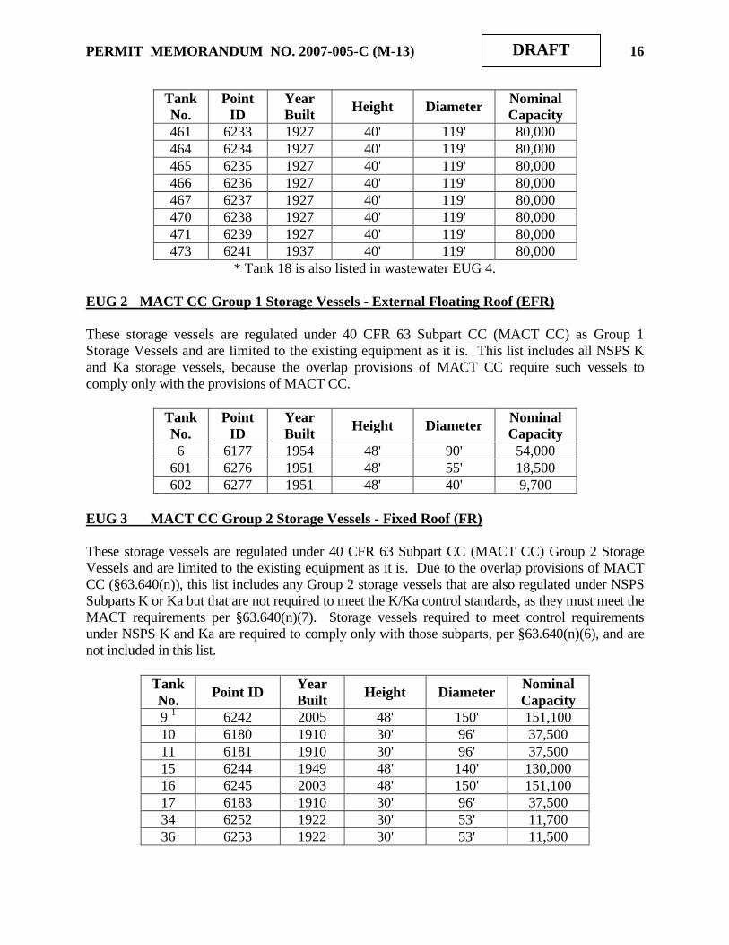
EUG 2 MACT CC Group 1 Storage Vessels - External Floating Roof (EFR)
These storage vessels are regulated under 40 CFR 63 Subpart CC (MACT CC) as Group 1
Storage Vessels and are limited to the existing equipment as it is. This list includes all NSPS K
and Ka storage vessels, because the overlap provisions of MACT CC require such vessels to
comply only with the provisions of MACT CC.
Tank
No.
Point
ID
Year
Built Height Diameter
Nominal
Capacity
6 6177 1954 48' 90' 54,000
601 6276 1951 48' 55' 18,500
602 6277 1951 48' 40' 9,700
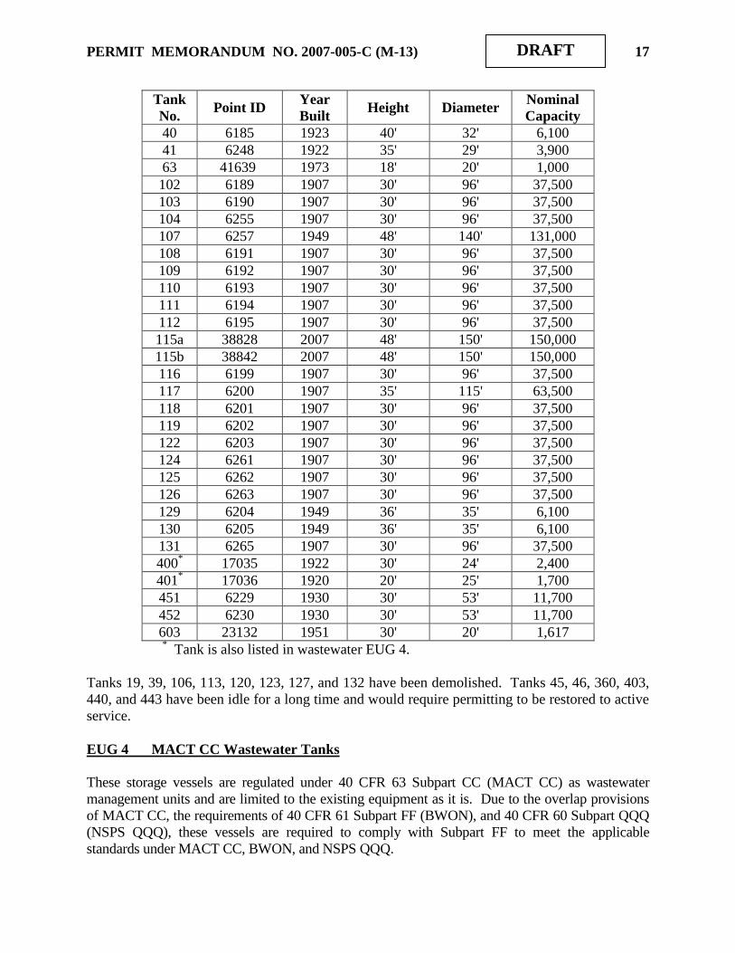
EUG 3 MACT CC Group 2 Storage Vessels - Fixed Roof (FR)
These storage vessels are regulated under 40 CFR 63 Subpart CC (MACT CC) Group 2 Storage
Vessels and are limited to the existing equipment as it is. Due to the overlap provisions of MACT
CC (§63.640(n)), this list includes any Group 2 storage vessels that are also regulated under NSPS
Subparts K or Ka but that are not required to meet the K/Ka control standards, as they must meet the
MACT requirements per §63.640(n)(7). Storage vessels required to meet control requirements
under NSPS K and Ka are required to comply only with those subparts, per §63.640(n)(6), and are
not included in this list.
Tank
No. Point ID
Year
Built Height Diameter
Nominal
Capacity
9 1 6242 2005 48' 150' 151,100
10 6180 1910 30' 96' 37,500
11 6181 1910 30' 96' 37,500
15 6244 1949 48' 140' 130,000
16 6245 2003 48' 150' 151,100
17 6183 1910 30' 96' 37,500
34 6252 1922 30' 53' 11,700
36 6253 1922 30' 53' 11,500
PERMIT MEMORANDUM NO. 2007-005-C (M-13) 17
DRAFT
Tank
No. Point ID
Year
Built Height Diameter
Nominal
Capacity
40 6185 1923 40' 32' 6,100
41 6248 1922 35' 29' 3,900
63 41639 1973 18' 20' 1,000
102 6189 1907 30' 96' 37,500
103 6190 1907 30' 96' 37,500
104 6255 1907 30' 96' 37,500
107 6257 1949 48' 140' 131,000
108 6191 1907 30' 96' 37,500
109 6192 1907 30' 96' 37,500
110 6193 1907 30' 96' 37,500
111 6194 1907 30' 96' 37,500
112 6195 1907 30' 96' 37,500
115a 38828 2007 48' 150' 150,000
115b 38842 2007 48' 150' 150,000
116 6199 1907 30' 96' 37,500
117 6200 1907 35' 115' 63,500
118 6201 1907 30' 96' 37,500
119 6202 1907 30' 96' 37,500
122 6203 1907 30' 96' 37,500
124 6261 1907 30' 96' 37,500
125 6262 1907 30' 96' 37,500
126 6263 1907 30' 96' 37,500
129 6204 1949 36' 35' 6,100
130 6205 1949 36' 35' 6,100
131 6265 1907 30' 96' 37,500
400* 17035 1922 30' 24' 2,400
401* 17036 1920 20' 25' 1,700
451 6229 1930 30' 53' 11,700
452 6230 1930 30' 53' 11,700
603 23132 1951 30' 20' 1,617 * Tank is also listed in wastewater EUG 4.
Tanks 19, 39, 106, 113, 120, 123, 127, and 132 have been demolished. Tanks 45, 46, 360, 403,
440, and 443 have been idle for a long time and would require permitting to be restored to active
service.
EUG 4 MACT CC Wastewater Tanks
These storage vessels are regulated under 40 CFR 63 Subpart CC (MACT CC) as wastewater
management units and are limited to the existing equipment as it is. Due to the overlap provisions
of MACT CC, the requirements of 40 CFR 61 Subpart FF (BWON), and 40 CFR 60 Subpart QQQ
(NSPS QQQ), these vessels are required to comply with Subpart FF to meet the applicable
standards under MACT CC, BWON, and NSPS QQQ.

PERMIT MEMORANDUM NO. 2007-005-C (M-13) 18
DRAFT
Tank
No.
Point
ID
Year
Built
Height Diameter Nominal
Capacity
13 6243 1976 40' 116' 75,250
181 6246 1910 30' 96' 37,500
4002 17035 1922 30' 24' 2,400
4012 17036 1920 20' 25' 1,700
4743 15940 1997 48' 106' 73,000
4753 15941 1997 48' 106' 73,000
1 Also listed in EUG 1
2 Also listed in EUG 3
3 Originally Kb tanks, converted to wastewater only.
EUG 5 NSPS Subpart Kb Storage Vessels - Internal Floating Roof (IFR)
These storage vessels are regulated under 40 CFR 60, NSPS Subpart Kb and are limited to the
existing equipment as it is. Due to the overlap provisions of MACT CC, these vessels are required
to comply only with NSPS Subpart Kb.
Tank
No.
Point
ID
Year
Built Height Diameter
Nominal
Capacity
4 23129 2003 48' 134' 120,600
31 6250 1998 48' 48' 15,000
472 6240 2007 48' 150' 140,000
605 6278 1951* 32' 30' 3,400 *Built as a fixed roof in 1951, converted to IFR in 1987, subject to Kb 1992.
EUG 6 Continuous Catalytic Reforming Unit (CCR)
This EUG was identified in the application for the initial TV permit as “Demolished Tanks.”
There was no need for such an EUG, so the number has been used for CCR. The CCR is
regulated by 40 CFR 63 Subpart UUU, and is limited to inorganic HAP of 10 ppmvd corrected to
3% oxygen at the regenerator stack. A new Point ID is pending. The CCR is among the process
units modified in this permit.
EUG 7 MACT CC Group 2 Storage Vessels External Floating Roof (EFR) Tank
This storage vessel is regulated under 40 CFR 63, Subpart CC (MACT CC) Group 2 Storage
Vessels and is limited to the existing equipment as it is. EUG 7 tanks contain low-vapor pressure
fluids and are not subject to OAC 252:100-37 and 39, while EUG 2 tanks contain gasoline or
other high vapor pressure liquids and are subject to those rules.
Tank
No.
Point
ID
Year
Built Height Diameter
Nominal
Capacity
114 6197 1949 48' 140' 131,000

PERMIT MEMORANDUM NO. 2007-005-C (M-13) 19
DRAFT
EUG 8 Fired Boilers
Each boiler exhausts approximately 60,000 acfm at an estimated 500°F from a 72" diameter
stack at 54´ above grade. Listed heat capacities are based on boilerplate capacity of 170,000
pounds/hour of 350 psi, 500 F steam. There were no emission limits applied to this EUG under
Title V but it was limited to the existing equipment as it is. These sources were to be regulated
under 40 CFR 63 Subpart DDDDD (MACT), however, that rule has been vacated. Per the CD,
the boilers became subject to NSPS Subpart J effective June 30, 2008. Each boiler is fitted with
SCR for control of NOX and compliance is monitored by CEMs.
ID Point ID Name/Model Heat Capacity Construction Date
1 6150 Babcock & Wilcox FH 26 233 MMBTUH 1950
2 6150 Babcock & Wilcox FH 26 233 MMBTUH 1950
3 6151 Babcock & Wilcox FH 26 233 MMBTUH 1950
4 6151 Babcock & Wilcox FH 26 233 MMBTUH 1955
EUG 9 Fuel-Burning Equipment
Various process heaters share stacks. Stack parameters follow. The June 30, 2008 CD states
that all fuel gas combustion devices (FGDs) are subject to NSPS Subpart J, effective June 30,
2008. The CD exempts the atmospheric heater and vacuum heater at the CDU from this
requirement until December 31, 2010.
Stack Height (ft) Diameter
(Ft) Temp ( F)
Flow
(ACFM)
CDU 175 11.5 500/800 67,000
FCCU Heaters 151 5.8 665 25,000
FCCU B-1 191 5 ** **
Unifiner 50 3.8 950 4,500
** This heater operates only upon recharging the catalyst, for approximately
four or five days out of a four-year period. Its exhaust is handled by
existing stacks, so individual data for these parameters are unknown.
The following table shows available information for all heaters. In most cases, the heat capacity
shown is based on Tulsa Refinery estimates provided during a June 1998 DEQ facility
inspection. These capacities may not accurately represent design capacities or maximum heat
rates, nor do they necessarily represent applicant‟s designation of heater duty.

PERMIT MEMORANDUM NO. 2007-005-C (M-13) 20
DRAFT
Source Point
ID
Manu-
facturer Burner Type
No. of
Burners
MMBTUH
(HHV)
Heater
Date
Atmospheric 6155 Foster-
Wheeler JZ-HEVD-12 26 200 1949
Vacuum 6155 Foster-
Wheeler JZ-HEVD-16 14 90 1949
FCCU Charge B-2 6158 M W
Kellogg JZ-VBM-14 32 150 1949
FCCU Air Heater
B-1 * 6159
M W
Kellogg Peabody M-18 1 38.4 1949
Unifiner Charge
H-1 6167
Refinery
Engr
JZ-UOV-4 Twin
head 12 42 1955
* vents to FCCU regenerator stack.
EUG 10 Sulfur Recovery Units
SRU #1 was constructed in 1972 and SRU #2 became operational in June 2006. Each unit has a
tail gas treating unit (TGTU) to scrub its exhaust. The TGTU #1 incinerator is rated at 5.6
MMBTUH and the TGTU #2 incinerator is rated at 12.1 MMBTUH. Scrubbed tail gas exhausts
TGTU #1 at 3,600 ACFM and 340 F through a 2 diameter stack at 200 above grade. Scrubbed
tail gas exhausts TGTU #2 at 6,450 ACFM at 780 F through a 2.5 diameter stack at 101 above
grade. SRU/TGTU #1 is Point ID 6152, and SRU/TGTU #2 is Point ID 36200.
The proposed NaSH Unit will supplement these units, reducing the amount of H2S sent to them.
EUG 11 FCCU
This EUG was formerly titled “FCCU Electrostatic Precipitator,” but that device has been
replaced. Catalyst is regenerated in the FCCU regeneration section, where cyclones remove
catalyst from the vent gas. Selective catalytic reduction (SCR) then controls NOX before the
exhaust stream reaches a wet gas scrubber (WGS), where SO2 and further PM removal occurs.
The only emission limits applied to this EUG are those imposed by the CD, as described in the
Specific Conditions. Compliance with SO2 and NOX standards are demonstrated by continuous
emission monitoring systems (CEMS) that monitor each pollutant and O2. Opacity has been
monitored by a continuous opacity monitoring system (COMS), but that system will not provide
reliable data in the water-rich environment downstream of the WGS. The facility has proposed
an alternative monitoring plan (AMP) to solve this problem. A copy of the AMP is found in the
Specific Conditions. Operation of the regenerator is regulated by MACT UUU. The ESP is
identified as Point ID 6153. The June 30, 2008 CD had required compliance with the opacity
standard of NSPS Subpart J by addition of COMS, effective June 30, 2008. It also established
the regenerator as an affected facility under NSPS Subpart J. Compliance dates as stated in the
CD and the modified CD depend on the pollutant and on the averaging period. These details are
identified in the Specific Conditions. Approximately 60,000 acfm (wet) at roughly 150°F is
exhausted through a 60" diameter stack at 151´ above grade.

PERMIT MEMORANDUM NO. 2007-005-C (M-13) 21
DRAFT
EUG 12 Flares
Each flare is steam assisted with three shielded pilots, flame front generators, and electronic
igniters. Pilot flame presence is detected with either infrared cameras or thermocouples in the
pilots. Throughputs are highly variable and exhaust temperatures are approximately 1,500 F.
The current #1 flare tip was designed in 1968 for 65,000 lbs/hr of 42 average molecular weight
gas. The #2 flare tip was designed for smokeless operation at 120,000 lbs/hr of 87 average
molecular weight gas and 42,000 lbs/hr of steam, and has a maximum capacity of 352,600 lbs/hr
of 67.8 average molecular weight gas. Both flare tips have a diameter of 5 . There are no
emission limits applied to this EUG under Title V but it is limited to the existing equipment as it
is. Sources in other EUGs under various regulations utilize the flares as air pollution control
devices. As noted in the discussion of the FCCU (Section II B), flare #1 handles the CDU,
FCCU, Alky, Poly, and Penex units, and flare #2 handles everything else. The flares are
identified as Point ID 6154.
Flare Make/Model Height (ft) Date
#1 Zink/STF-SA-18 230 1949
#2 Zink/STF-SA-36-C 250 1972
EUG 13 MACT EEEE Tanks
This EUG contains vessels subject to 40 CFR 63 Subpart EEEE. Because these perchloroethylene
tanks are smaller than 5,000 gallons, these emission sources do not require control, per Subsection
63.2343(a).
Tank No. Year
Built Height Diameter
Nominal
Capacity
10F-163 (CCR) 2007 4' 8' 18 bbl
4V-31 (Unifiner) 2002 13.5' 4.5' 30 bbl
EUG 14 Low Vapor Pressure Loading Operations
There are several loading racks that handle materials that are not treated as VOCs under OAC
Subchapters 37 and 39. All of these racks were constructed in 1949. These units are
“grandfathered” (constructed prior to any applicable rule). There are no emission limits or
compliance obligations applied to this EUG under Title V but it is limited to the existing
equipment as it is.
Rack Point ID Material Capacity
Black Oil Railcar 6169 Asphalt, flux, vacuum tower bottoms 12 cars
Black Oil Truck 6170 Asphalt, flux, vacuum tower bottoms 3 trucks
Diesel Railcar 14488 #2 Diesel 8 cars
Gas oil Truck 6181 Gas oils 2 trucks

PERMIT MEMORANDUM NO. 2007-005-C (M-13) 22
DRAFT
EUG 15 High Vapor Pressure Loading Operations
There are several loading racks that handle VOC materials. The propylene and butane truck
loading facilities are on vapor balance systems. The propane truck loading rack is on vapor
balance with the propane tanks or fuel gas system at the refinery. Emissions from the terminal
gasoline and diesel rack are vented to a vapor combustion device. This device exhausts at 35
above grade. All units except the propylene and HSR racks are “grandfathered” (constructed
prior to any applicable rule). The HSR rack is an affected equipment item under MACT EEEE,
but there are no standards that apply. There are no emission limits applied to this EUG under
Title V but it is limited to the existing equipment as it is.
Rack Point ID Material Capacity Date
Butane truck 6171 Butane loading and unloading 4 trucks 1923
Propylene 13404 Propylene loading 2 cars,
2 trucks
Railcars/1996,
Trucks/1997
Terminal 6275 Gasoline and diesel 4 trucks 1951
Terminal 6275 Propane 1 truck 1951
HSR loading 41481 Heavy straight run naphtha 1 truck 2008*
*Old rack reactivated in 2008.
EUG 16 Fugitive Emissions
Equipment leak emissions from components throughout the entire refinery, including but not
limited to the process units, storage tanks, and the terminal are included in this Group. There are
no annual emission limits applied to this EUG under Title V but it is limited to the existing
equipment as it is. VOC concentrations in ppm are limited by various rules and regulations,
including MACT CC and OAC 252:100-39-15. Aggregated emission points are identified as
Point ID 6172.
EUG 17 Wastewater System
The wastewater system consists of several different sewer systems and the wastewater treatment
plant, as described in Part N of Section II (Facility Description) above. The facility is subject to
40 CFR 61 Subpart FF (BWON) and 40 CFR 63 Subpart CC (MACT CC), while areas of the
refinery are subject to 40 CFR 60 Subpart QQQ (NSPS QQQ). Due to the overlap regulations
under MACT CC (40 CFR 63.640(o)), all Group 1 wastewater streams also regulated under
NSPS QQQ must meet only MACT CC standards, while all Group 1 wastewater streams also
regulated under BWON must meet only BWON standards. A June 11, 2007, EPA Applicability
Determination (AD) issued to BP Products North America and signed by George Czerniak, states
that a Group 2 wastewater stream may be treated under BWON exclusively if the facility
declares it to be Group 1 and satisfies the requirements of FF for the stream. Given this AD, the
entire SCAN Unit, entire NHDS Unit, and new construction at the DHTU and CCR are subject
to BWON. The entire SRU/TGTU #2 is subject to NSPS QQQ. Aggregated emission points are
identified as Point ID 13409.
PERMIT MEMORANDUM NO. 2007-005-C (M-13) 23
DRAFT
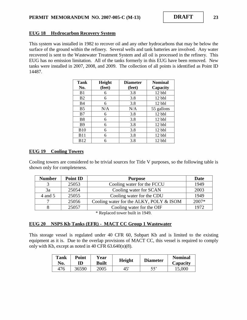
EUG 18 Hydrocarbon Recovery System
This system was installed in 1982 to recover oil and any other hydrocarbons that may be below the
surface of the ground within the refinery. Several wells and tank batteries are involved. Any water
recovered is sent to the Wastewater Treatment System and all oil is processed in the refinery. This
EUG has no emission limitation. All of the tanks formerly in this EUG have been removed. New
tanks were installed in 2007, 2008, and 2009. The collection of all points is identified as Point ID
14487.
Tank
No.
Height
(feet)
Diameter
(feet)
Nominal
Capacity
B1 6 3.8 12 bbl
B2 6 3.8 12 bbl
B4 6 3.8 12 bbl
B5 N/A N/A 55 gallons
B7 6 3.8 12 bbl
B8 6 3.8 12 bbl
B9 6 3.8 12 bbl
B10 6 3.8 12 bbl
B11 6 3.8 12 bbl
B12 6 3.8 12 bbl
EUG 19 Cooling Towers
Cooling towers are considered to be trivial sources for Title V purposes, so the following table is
shown only for completeness.
Number Point ID Purpose Date
3 25053 Cooling water for the FCCU 1949
3a 25054 Cooling water for SCAN 2003
4 and 5 25055 Cooling water for the CDU 1949
7 25056 Cooling water for the ALKY, POLY & ISOM 2007*
8 25057 Cooling water for the OIF 1972 * Replaced tower built in 1949.
EUG 20 NSPS Kb Tanks (EFR) - MACT CC Group 1 Wastewater
This storage vessel is regulated under 40 CFR 60, Subpart Kb and is limited to the existing
equipment as it is. Due to the overlap provisions of MACT CC, this vessel is required to comply
only with Kb, except as noted in 40 CFR 63.640(n)(8).
Tank
No.
Point
ID
Year
Built Height Diameter
Nominal
Capacity
476 36590 2005 45' 55‟ 15,000

PERMIT MEMORANDUM NO. 2007-005-C (M-13) 24
DRAFT
EUG 21 Pressurized Spheres
These units are “grandfathered” (constructed prior to any applicable rule). There are no emission
limits applied to this EUG under Title V but it is limited to the existing equipment as it is.
Because there are no measurable emissions from any of these tanks, they are all classified as
Insignificant, and listed here only for completeness.
Tank
No.
Point ID
Year
Built
Diameter
(feet)
Nominal
Capacity (bbls)
207
6281
1948
48
9,250
208
6282
1924
48
9,250
218
6284
1986
55
13,750
219
6285
1986
55
13,750
220
6286
1953
51
10,800
221
6287
1953
51
10,800
EUG 22 Pressurized Bullet Tanks
Because there are no measurable emissions from these tanks, they are all classified as
Insignificant, and listed only for completeness.
Tank No.
Point ID
Year Built
Length
(feet)
Diameter
(feet)
Nominal
Capacity
(bbls)
58
6288
1960
66
12
1,300
59
6289
1960
66
12
1,300
60
6290
1960
66
12
1,300
64
6291
1967
84
10
1,300
65
6292
1967
84
10
1,300
66
6293
1967
84
10
1,300
70
6294
1979
70
11
1,000
71
6295
1979
70
11
1,000
72
6296
1998
78
10
1,000
73
6297
1998
78
10
1,000
PERMIT MEMORANDUM NO. 2007-005-C (M-13) 25
DRAFT
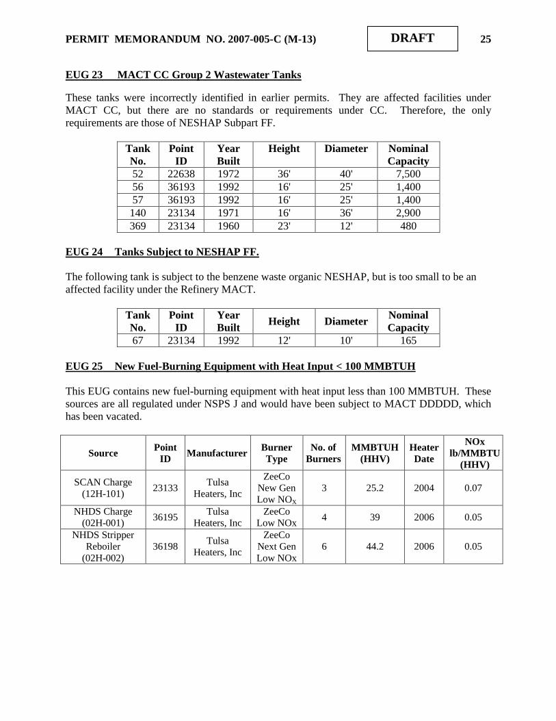
EUG 23 MACT CC Group 2 Wastewater Tanks
These tanks were incorrectly identified in earlier permits. They are affected facilities under
MACT CC, but there are no standards or requirements under CC. Therefore, the only
requirements are those of NESHAP Subpart FF.
Tank
No.
Point
ID
Year
Built
Height Diameter Nominal
Capacity
52 22638 1972 36' 40' 7,500
56 36193 1992 16' 25' 1,400
57 36193 1992 16' 25' 1,400
140 23134 1971 16' 36' 2,900
369 23134 1960 23' 12' 480
EUG 24 Tanks Subject to NESHAP FF.
The following tank is subject to the benzene waste organic NESHAP, but is too small to be an
affected facility under the Refinery MACT.
Tank
No.
Point
ID
Year
Built Height Diameter
Nominal
Capacity
67 23134 1992 12' 10' 165
EUG 25 New Fuel-Burning Equipment with Heat Input < 100 MMBTUH
This EUG contains new fuel-burning equipment with heat input less than 100 MMBTUH. These
sources are all regulated under NSPS J and would have been subject to MACT DDDDD, which
has been vacated.
Source Point
ID Manufacturer
Burner
Type
No. of
Burners
MMBTUH
(HHV)
Heater
Date
NOx
lb/MMBTU
(HHV)
SCAN Charge
(12H-101) 23133
Tulsa
Heaters, Inc
ZeeCo
New Gen
Low NOX
3 25.2 2004 0.07
NHDS Charge
(02H-001) 36195
Tulsa
Heaters, Inc
ZeeCo
Low NOx 4 39 2006 0.05
NHDS Stripper
Reboiler
(02H-002)
36198 Tulsa
Heaters, Inc
ZeeCo
Next Gen
Low NOx
6 44.2 2006 0.05
PERMIT MEMORANDUM NO. 2007-005-C (M-13) 26
DRAFT
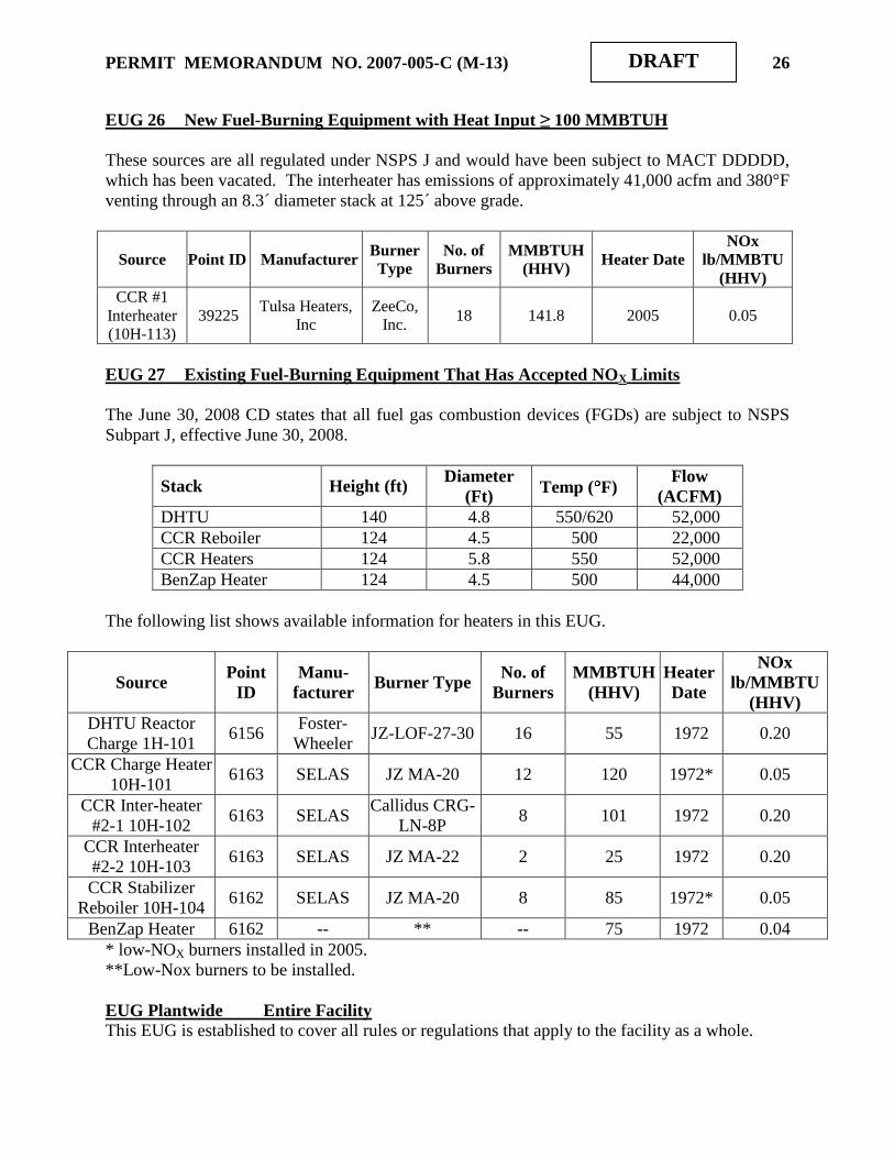
EUG 26 New Fuel-Burning Equipment with Heat Input ≥ 100 MMBTUH
These sources are all regulated under NSPS J and would have been subject to MACT DDDDD,
which has been vacated. The interheater has emissions of approximately 41,000 acfm and 380°F
venting through an 8.3´ diameter stack at 125´ above grade.
Source Point ID Manufacturer Burner
Type
No. of
Burners
MMBTUH
(HHV) Heater Date
NOx
lb/MMBTU
(HHV)
CCR #1
Interheater
(10H-113)
39225 Tulsa Heaters,
Inc
ZeeCo,
Inc. 18 141.8 2005 0.05
EUG 27 Existing Fuel-Burning Equipment That Has Accepted NOX Limits
The June 30, 2008 CD states that all fuel gas combustion devices (FGDs) are subject to NSPS
Subpart J, effective June 30, 2008.
Stack Height (ft) Diameter
(Ft) Temp ( F)
Flow
(ACFM)
DHTU 140 4.8 550/620 52,000
CCR Reboiler 124 4.5 500 22,000
CCR Heaters 124 5.8 550 52,000
BenZap Heater 124 4.5 500 44,000
The following list shows available information for heaters in this EUG.
Source Point
ID
Manu-
facturer Burner Type
No. of
Burners
MMBTUH
(HHV)
Heater
Date
NOx
lb/MMBTU
(HHV)
DHTU Reactor
Charge 1H-101 6156
Foster-
Wheeler JZ-LOF-27-30 16 55 1972 0.20
CCR Charge Heater
10H-101 6163 SELAS JZ MA-20 12 120 1972* 0.05
CCR Inter-heater
#2-1 10H-102 6163 SELAS
Callidus CRG-
LN-8P 8 101 1972 0.20
CCR Interheater
#2-2 10H-103 6163 SELAS JZ MA-22 2 25 1972 0.20
CCR Stabilizer
Reboiler 10H-104 6162 SELAS JZ MA-20 8 85 1972* 0.05
BenZap Heater 6162 -- ** -- 75 1972 0.04
* low-NOX burners installed in 2005.
**Low-Nox burners to be installed.
EUG Plantwide Entire Facility
This EUG is established to cover all rules or regulations that apply to the facility as a whole.

PERMIT MEMORANDUM NO. 2007-005-C (M-13) 27
DRAFT
IV. EMISSIONS
Unless otherwise stated, all emission estimates in Section IV reflect operations as reported in the
2005 and 2006 Inventory Turn-Around Documents. Additionally, most VOC emissions are non-
HAP only, unless otherwise indicated. HAP emissions were calculated EUG by EUG in the
memorandum associated with the initial TV permit, and the reader may peruse that memorandum
for more information concerning the methods used. HAP emissions reported for 2006 will be
presented in aggregate near the end of this Section IV. Tanks shown as “Out of Service” or
“Idle” had no activity in 2006. The “Contents” column of each table for tanks reflects
information presented in the Turn-Around Document, and does not represent a classification or
requirement. Assumptions and data used in calculating emissions for each EUG are reflected in
the following analyses.
Section “A” will deal with emissions increases attributable to the refinery integration project,
while Section “B” will list emissions from the refinery as a whole.
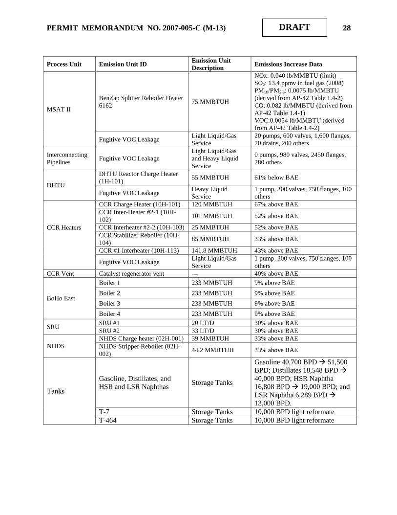
A. Emissions Increases
Emissions changes are based on the following assumptions. For the “new” BenZap Splitter
Reboiler, NOx emissions will be 0.040 lb/MMBTU, while CO, VOC, and PM will be calculated
using AP-42 (7/98), Section 1.4.
“Baseline actual emissions” (BAE) calculations began with 2008-2009 Emissions Inventories for
everything but SO2 and 2005-2006 for SO2. BAE were adjusted to multiply new emissions limits
from the Consent Decree by old production rates.
For each unit, past 10-year historical operations and planned production schedules were
evaluated. The information was used to determine future per unit emissions increases that could
be accommodated without total integrated refinery emissions increases triggering PSD
applicability thresholds. This determination was based on the case that best represented the wide
range of potential operating scenarios while ensuring PAE remained below significance levels.
For combustion units, including boilers, heaters, tail-gas incinerators and engines, estimated PAE
was calculated using the maximum projected annual average hourly heat input associated with
planned production, and representative emission factors. Emission increases in components were
based on a conservative number of added components for the project.
Process Unit Emission Unit ID Emission Unit
Description Emissions Increase Data
NaSH, FGR and
Other Projects
NaSH Sulfur Recovery No VOC emissions Included in Boiler #1-4 Utilization
Increase
Coker Blowdown/Flare Gas
Recovery
Emissions part of
flare emissions 90% below BAE
Fugitive VOC Leakage
Light Liquid/Gas
and Heavy Liquid
Service
22 pumps, 1,900 valves, 4,850
flanges, 20 drains, 600 others
PERMIT MEMORANDUM NO. 2007-005-C (M-13) 28
DRAFT
Process Unit Emission Unit ID Emission Unit
Description Emissions Increase Data
MSAT II
BenZap Splitter Reboiler Heater
6162 75 MMBTUH
NOx: 0.040 lb/MMBTU (limit)
SO2: 13.4 ppmv in fuel gas (2008)
PM10/PM2.5: 0.0075 lb/MMBTU
(derived from AP-42 Table 1.4-2)
CO: 0.082 lb/MMBTU (derived from
AP-42 Table 1.4-1)
VOC:0.0054 lb/MMBTU (derived
from AP-42 Table 1.4-2)
Fugitive VOC Leakage Light Liquid/Gas
Service
20 pumps, 600 valves, 1,600 flanges,
20 drains, 200 others
Interconnecting
Pipelines Fugitive VOC Leakage
Light Liquid/Gas
and Heavy Liquid
Service
0 pumps, 980 valves, 2450 flanges,
280 others
DHTU
DHTU Reactor Charge Heater
(1H-101) 55 MMBTUH 61% below BAE
Fugitive VOC Leakage Heavy Liquid
Service
1 pump, 300 valves, 750 flanges, 100
others
CCR Heaters
CCR Charge Heater (10H-101) 120 MMBTUH 67% above BAE
CCR Inter-Heater #2-1 (10H-
102) 101 MMBTUH 52% above BAE
CCR Interheater #2-2 (10H-103) 25 MMBTUH 52% above BAE
CCR Stabilizer Reboiler (10H-
104) 85 MMBTUH 33% above BAE
CCR #1 Interheater (10H-113) 141.8 MMBTUH 43% above BAE
Fugitive VOC Leakage Light Liquid/Gas
Service
1 pump, 300 valves, 750 flanges, 100
others
CCR Vent Catalyst regenerator vent --- 40% above BAE
BoHo East
Boiler 1 233 MMBTUH 9% above BAE
Boiler 2 233 MMBTUH 9% above BAE
Boiler 3 233 MMBTUH 9% above BAE
Boiler 4 233 MMBTUH 9% above BAE
SRU SRU #1 20 LT/D 30% above BAE
SRU #2 33 LT/D 30% above BAE
NHDS
NHDS Charge heater (02H-001) 39 MMBTUH 33% above BAE
NHDS Stripper Reboiler (02H-
002) 44.2 MMBTUH 33% above BAE
Tanks
Gasoline, Distillates, and
HSR and LSR Naphthas Storage Tanks
Gasoline 40,700 BPD 51,500
BPD; Distillates 18,548 BPD
40,000 BPD; HSR Naphtha
16,808 BPD 19,000 BPD; and
LSR Naphtha 6,289 BPD
13,000 BPD.
T-7 Storage Tanks 10,000 BPD light reformate
T-464 Storage Tanks 10,000 BPD light reformate

PERMIT MEMORANDUM NO. 2007-005-C (M-13) 29
DRAFT
Process Unit Emission Unit ID Emission Unit
Description Emissions Increase Data
CDU East CDU Atmospheric Heater 200 MMBTUH 31% below BAE
CDU Vacuum Heater 90 MMBTUH 31% below BAE
FCCU FCC Charge Heater B-2 150 MMBTUH 15% above BAE
FCCU Regenerator --- 15% above BAE
Isomerization Isomerization Unifiner Heater 35 MMBTUH 90% above BAE
Scanfiner Scanfiner Charge Heater 25.2 MMBTUH 59% above BAE
CDU West
CDU Atmospheric Tower
Heater H-1 280 MMBTUH 4% above BAE
CDU #1 Vacuum Tower Heater
H-2 67.2 MMBTUH 5% above BAE
CDU #2 Vacuum Tower Heater
H-3 43.2 MMBTUH 4% below BAE
Unifiner
Unifiner Charge Heater 36.7 MMBTUH 47% below BAE
Unifiner Stripper Reboiler
Heater 59.5 MMBTUH
47% below BAE
Unifiner H2 Recycle
Compressor 2.4 MMBTUH
47% below BAE
Platformer
No. 2 Platformer Charge Heater
PH-1/2 86.8 MMBTUH 42% below BAE
No. 2 Platformer Charge Heater
PH-3 36.3 MMBTUH
42% below BAE
No. 2 Platformer Charge Heater
PH-4 44.8 MMBTUH
42% below BAE
No. 2 Platformer Charge Heater
PH-5 65.3 MMBTUH
42% below BAE
No. 2 Platformer Charge Heater
PH-6 34.8 MMBTUH
42% below BAE
No. 2 Platformer Charge Heater
PH-7 25.6 MMBTUH
42% below BAE
Coker Coker Drum Charge Heater B-1 60 MMBTUH 22% above BAE
Coker Preheater H-3 32.2 MMBTUH 22% above BAE
LEU
LEU Raffinate Mix Heater H-
101 22.4 MMBTUH 23% above BAE
LEU Extract mix Heater H-102 150 MMBTUH 23% above BAE
LEU Hydrotreater Charge
Heater H-201 22.4 MMBTUH 23% above BAE
All combustion PM10 was assumed to be PM2.5.

PERMIT MEMORANDUM NO. 2007-005-C (M-13) 30
DRAFT
i. Baseline Actual Emissions
Unit NOx
TPY
SO2
TPY
VOC
TPY
PM10
TPY
PM2.5
TPY
CO
TPY
DHTU Charge (1H-101) 24.71 2.83 0.88 1.22 1.22 13.51
DHTU Modifications (Fugitives) -- -- -- -- -- --
CCR Charge Heater (10H-101) 13.22 4.18 1.30 1.80 1.80 19.91
CCR Interheater #2-1 (10H-102) 20.57 2.28 0.71 0.99 0.99 10.89
CCR Interheater #2-2 (10H-103) 7.35 1.06 0.33 0.46 0.46 5.08
CCR Splitter & Stabilizer (10H-104) 4.41 1.71 0.53 0.74 0.74 0.10
CCR Interheater #1 (10H-113) 16.81 7.04 2.20 3.04 3.04 33.57
CCR Regenerator Vent 0.06 0.08 6.10 -- -- 0.68
CCR Modifications (Fugitives) -- -- -- -- -- --
Boiler 1 13.72 8.62 2.55 3.53 3.53 39.00
Boiler 2 13.72 8.62 2.55 3.53 3.53 39.00
Boiler 3 13.72 8.62 2.55 3.53 3.53 39.00
Boiler 4 13.72 8.62 2.55 3.53 3.53 39.00
SRU #1 1.02 0.13 0.04 0.06 0.06 42.90
SRU #2 2.07 0.38 0.13 0.17 0.17 1.93
NHDS Charge Heater (02H-001) 3.80 1.54 0.48 0.66 0.66 0.04
NHDS Reboiler Heater (02H-002) 2.94 1.18 0.37 0.51 0.51 0.39
Tanks -- -- 183.24 -- -- --
Crude Vacuum Charge (A Heater) 92.05 2.80 4.16 5.75 5.75 63.57
Crude Vacuum Charge #2 Heater 45.34 1.38 2.05 2.83 2.83 31.31
FCC Charge Heater (B-2) 39.45 3.67 1.42 1.97 1.97 21.76
FCCU Regenerator 23.63 42.22 1.79 28.04 28.04 34.09
Isomerization Unifiner Heater 8.06 1.16 0.44 0.60 0.60 6.65
Scanfiner Charge Heater 1.33 0.44 0.10 0.14 0.14 0.01
Flares (No. 1 and No. 2) 4.32 0.25 0.38 -- -- 21.97
Loading/Unloading Racks -- -- 9.66 -- -- --
Loading Terminal 2.45 -- 12.14 -- -- 6.21
Fugitives -- -- 211.06 4.81 4.81 --
Wastewater System -- -- 232.71 -- -- --
Cooling Towers -- -- 19.40 62.41 62.41 --
Coker Blowdown/Flare Gas Recovery 2.35 10.97 21.33 -- -- 12.78
#3 Boiler 115.39 317.91 2.27 3.60 3.60 34.74
#4 Boiler 114.32 317.91 2.25 3.57 3.57 34.43
#7 Boiler 51.28 0 1.46 2.01 2.01 22.23
#8 Boiler 53.99 0 1.53 2.12 2.12 23.40
#9 Boiler 52.40 0 2.02 2.79 2.79 30.82

PERMIT MEMORANDUM NO. 2007-005-C (M-13) 31
DRAFT
Unit NOx
TPY
SO2
TPY
VOC
TPY
PM10
TPY
PM2.5
TPY
CO
TPY
CDU Atmosphere Tower Heater (H-1) 98.29 1039.55 5.04 6.97 6.97 77.02
CDU #1 Vacuum Tower Heater (H-2) 27.29 342.97 1.51 2.09 2.09 23.13
CDU #2 Vacuum Tower Heater (H-3) 10.12 121.49 0.56 0.77 0.77 8.56
PDA Propane Compressor 0.90 0.01 1.04 0.18 0.18 3.58
Unifiner Charge Heater 8.61 48.34 0.30 0.42 0.42 4.59
Unifiner Stripper Reboiler Heater 14.47 76.36 0.50 0.70 0.70 7.70
Unifiner H2 Recycle Compressor 0.36 0 1.26 0.22 0.22 4.35
No. 2 Platformer Charge Heater (PH-
1/2) 28.13 184.74 0.99 1.36 1.36 15.05
No. 2 Platformer Charge Heater (PH-3) 8.18 55.86 0.29 0.40 0.40 4.37
No. 2 Platformer Charge Heater (PH-4) 7.06 38.02 0.25 0.34 0.34 3.76
No. 2 Platformer Charge Heater (PH-5) 21.58 0 1.26 1.74 1.74 19.27
No. 2 Platformer Charge Heater (PH-6) 9.84 0 0.58 0.80 0.80 8.79
No. 2 Platformer Charge Heater (PH-7) 3.81 29.86 0.13 0.18 0.18 2.04
Coker Drum Charge Heater (B-1) 11.28 0 0.68 0.93 0.93 10.32
Coker Preheater (H-3) 6.24 0 0.37 0.52 0.52 5.71
LEU Raffinate Mix Heater (H101) 8.69 66.41 0.32 0.44 0.44 4.86
LEU Extract Mix Heater (H102) 33.09 587.93 2.02 2.79 2.79 30.81
LEU Hydrotreater Charge Heater
(H201) 9.89 104.01 0.42 0.58 0.58 6.41
MEK - Wax Free Oil Heater 32.67 0.00 1.17 1.62 1.62 17.94
MEK - Soft Wax Heater (H-2) 12.12 104.77 0.56 0.77 0.77 8.54
WPU Flare 0 0 0 -- -- 0
Coker Flare 0.22 -- 0.49 -- -- 1.18
Lube Flare 0.09 -- 0.21 -- -- 0.51
Cooling Tower Pumps 4.84 0.03 5.60 0.97 0.97 19.31
Diesel Emergency Generators 0.28 0.01 0.11 0.01 0.01 2.94
Gasoline Engines (<600 hp) 0.70 0.02 0.05 -- -- 0.15
Loading/Unloading Racks -- -- 2.26 -- -- --
Tanks -- -- 101.90 -- -- --
Fugitives -- -- 58.78 -- -- --
Wastewater System -- -- 210.57 -- -- --
Cooling Towers -- -- 18.84 204.72 204.72 --
TOTALS 1116.9 3556.0 1150.8 373.9 373.9 919.9

PERMIT MEMORANDUM NO. 2007-005-C (M-13) 32
DRAFT
ii. Projected Actual Emissions
Unit NOx
TPY
SO2
TPY
VOC
TPY
PM10
TPY
PM2.5
TPY
CO
TPY
MSAT Project 26.99 1.43 11.57 4.29 4.29 47.50
NaSH Sulfur Recovery 1.57 0.13 0.28 0.39 0.39 4.33
NaSH, FGR and Other Fugitives -- -- 19.06 -- -- --
Interconnecting Pipelines -- -- 8.28 -- -- --
DHTU Charge (1H-101) 9.64 0.59 1.30 1.79 1.79 19.84
DHTU Modifications (Fugitives) -- -- 2.73 -- -- --
CCR Charge Heater (10H-101) 17.58 0.79 1.73 2.39 2.39 26.46
CCR Interheater #2-1 (10H-102) 27.34 0.43 0.95 1.31 1.31 14.48
CCR Interheater #2-2 (10H-103) 9.76 0.20 0.44 0.61 0.61 6.75
CCR Splitter & Stabilizer (10H-104) 5.86 0.32 0.71 0.98 0.98 0.13
CCR Interheater #1 (10H-113) 22.34 1.34 2.92 4.04 4.04 44.61
CCR Regenerator Vent 0.07 0.09 8.11 -- -- 0.75
CCR Modifications (Fugitives) -- -- 2.60 -- -- 0.00
Boiler 1 13.92 1.25 2.59 3.58 3.58 39.58
Boiler 2 13.92 1.25 2.59 3.58 3.58 39.58
Boiler 3 13.92 1.25 2.59 3.58 3.58 39.58
Boiler 4 13.92 1.25 2.59 3.58 3.58 39.58
SRU #1 1.33 0.16 0.06 0.08 0.08 55.77
SRU #2 2.69 0.49 0.16 0.23 0.23 2.51
NHDS Charge Heater (02H-001) 5.05 0.29 0.64 0.88 0.88 0.06
NHDS Reboiler Heater (02H-002) 3.90 0.22 0.49 0.68 0.68 0.52
Tanks -- -- 184.58 -- -- --
Crude Vacuum Charge (A Heater) 63.43 10.96 2.87 3.96 3.96 43.81
Crude Vacuum Charge #2 Heater 31.24 5.40 1.41 1.95 1.95 21.58
FCC Charge Heater (B-2) 45.33 0.60 1.64 2.26 2.26 25.00
FCCU Regenerator 27.15 48.51 2.06 32.22 32.22 39.17
Isomerization Unifiner Heater 15.33 0.31 0.83 1.14 1.14 12.64
Scanfiner Charge Heater 2.11 0.10 0.16 0.23 0.23 0.01
Flares (No. 1 and No. 2) 4.32 0.25 0.38 -- -- 21.97
Loading/Unloading Racks 0.00 0.00 9.66 0.00 0.00 --
Loading Terminal 2.45 0.00 12.14 0.00 0.00 6.21
Fugitives 0.00 0.00 211.06 4.81 4.81 0.00
Wastewater System 0.00 0.00 232.71 0.00 0.00 0.00
Cooling Towers 0.00 0.00 19.40 62.41 62.41 0.00
Coker Blowdown/Flare Gas Recovery 0.23 1.10 2.13 -- -- 1.28
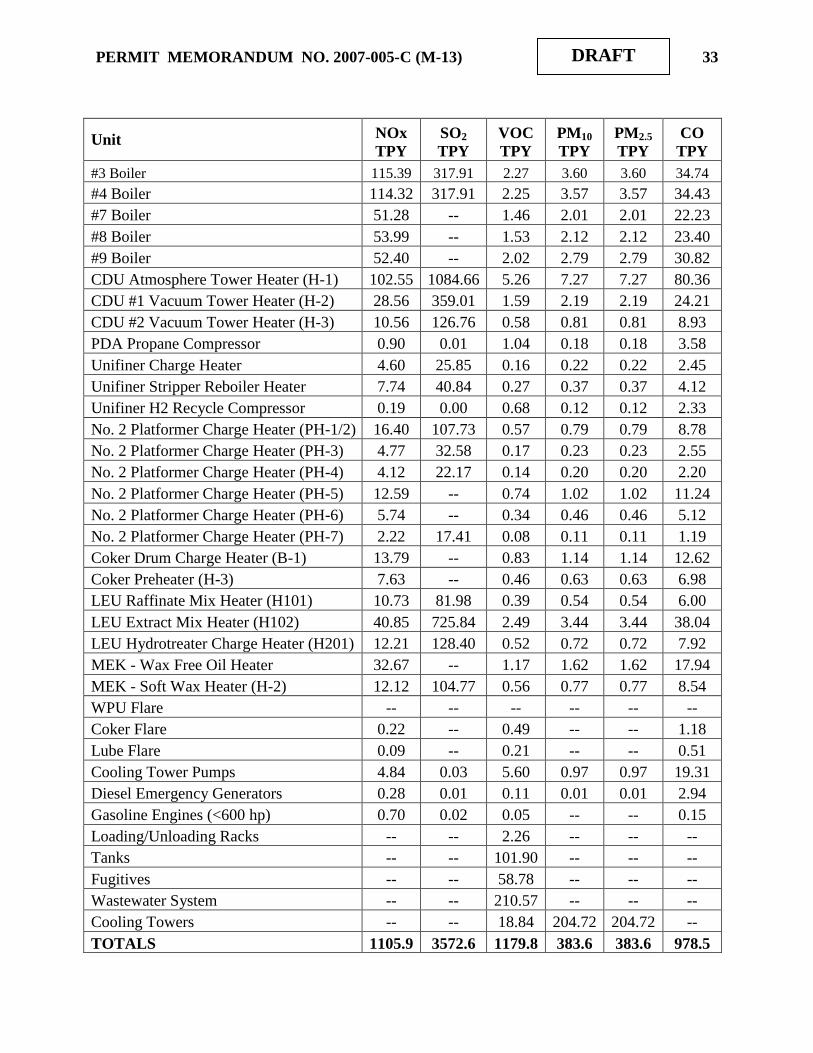
PERMIT MEMORANDUM NO. 2007-005-C (M-13) 33
DRAFT
Unit NOx
TPY
SO2
TPY
VOC
TPY
PM10
TPY
PM2.5
TPY
CO
TPY
#3 Boiler 115.39 317.91 2.27 3.60 3.60 34.74
#4 Boiler 114.32 317.91 2.25 3.57 3.57 34.43
#7 Boiler 51.28 -- 1.46 2.01 2.01 22.23
#8 Boiler 53.99 -- 1.53 2.12 2.12 23.40
#9 Boiler 52.40 -- 2.02 2.79 2.79 30.82
CDU Atmosphere Tower Heater (H-1) 102.55 1084.66 5.26 7.27 7.27 80.36
CDU #1 Vacuum Tower Heater (H-2) 28.56 359.01 1.59 2.19 2.19 24.21
CDU #2 Vacuum Tower Heater (H-3) 10.56 126.76 0.58 0.81 0.81 8.93
PDA Propane Compressor 0.90 0.01 1.04 0.18 0.18 3.58
Unifiner Charge Heater 4.60 25.85 0.16 0.22 0.22 2.45
Unifiner Stripper Reboiler Heater 7.74 40.84 0.27 0.37 0.37 4.12
Unifiner H2 Recycle Compressor 0.19 0.00 0.68 0.12 0.12 2.33
No. 2 Platformer Charge Heater (PH-1/2) 16.40 107.73 0.57 0.79 0.79 8.78
No. 2 Platformer Charge Heater (PH-3) 4.77 32.58 0.17 0.23 0.23 2.55
No. 2 Platformer Charge Heater (PH-4) 4.12 22.17 0.14 0.20 0.20 2.20
No. 2 Platformer Charge Heater (PH-5) 12.59 -- 0.74 1.02 1.02 11.24
No. 2 Platformer Charge Heater (PH-6) 5.74 -- 0.34 0.46 0.46 5.12
No. 2 Platformer Charge Heater (PH-7) 2.22 17.41 0.08 0.11 0.11 1.19
Coker Drum Charge Heater (B-1) 13.79 -- 0.83 1.14 1.14 12.62
Coker Preheater (H-3) 7.63 -- 0.46 0.63 0.63 6.98
LEU Raffinate Mix Heater (H101) 10.73 81.98 0.39 0.54 0.54 6.00
LEU Extract Mix Heater (H102) 40.85 725.84 2.49 3.44 3.44 38.04
LEU Hydrotreater Charge Heater (H201) 12.21 128.40 0.52 0.72 0.72 7.92
MEK - Wax Free Oil Heater 32.67 -- 1.17 1.62 1.62 17.94
MEK - Soft Wax Heater (H-2) 12.12 104.77 0.56 0.77 0.77 8.54
WPU Flare -- -- -- -- -- --
Coker Flare 0.22 -- 0.49 -- -- 1.18
Lube Flare 0.09 -- 0.21 -- -- 0.51
Cooling Tower Pumps 4.84 0.03 5.60 0.97 0.97 19.31
Diesel Emergency Generators 0.28 0.01 0.11 0.01 0.01 2.94
Gasoline Engines (<600 hp) 0.70 0.02 0.05 -- -- 0.15
Loading/Unloading Racks -- -- 2.26 -- -- --
Tanks -- -- 101.90 -- -- --
Fugitives -- -- 58.78 -- -- --
Wastewater System -- -- 210.57 -- -- --
Cooling Towers -- -- 18.84 204.72 204.72 --
TOTALS 1105.9 3572.6 1179.8 383.6 383.6 978.5

PERMIT MEMORANDUM NO. 2007-005-C (M-13) 34
DRAFT
EMISSION INCREASES
Pollutant
Emission Increases,
TPY
PSD Level of
Significance, TPY
PSD Review
Commences?
NOx -11.1 40 No
SO2 16.7 40 No
VOC 29.0 40 No
PM10 9.7 15 No
PM2.5 9.7 10 No
CO 58.6 100 No
B. Refinery Potential Emissions
EUG 1 MACT CC Group 1 Storage Vessels - Internal Floating Roof (IFR)
VOC emissions are calculated using the current version of EPA‟s TANKS program.
Tank # Contents Turnovers TPY
1 Crude 21.5 2.09
2 Crude 28.5 5.38
3 Crude 106 3.36
7 HSR / Light Reformate 63.7 18.5
8 Crude 27.9 2.09
14 HSR 2.87 8.47
18 Slop oil 4.62 5.24
442 Gasoline blendstock 6.22 0.73
444 Gasoline blendstock 7.35 0.52
445 Gasoline blendstock 70.6 1.12
446 Gasoline blendstock 5.16 0.90
447 Gasoline blendstock 40.4 2.68
450 Gasoline 16.5 2.24
459 ISOM feedstock 23.3 8.91
460 Gasoline 28.1 11.2
461 Gasoline 9.44 5.28
464 Gasoline 16.3 6.84
465 Gasoline 10.3 6.28
466 Gasoline 26.5 5.31
467 Gasoline 24.9 7.46
470 Gasoline 17.0 4.71
471 Gasoline 1.92 0.33
473 Gasoline 11.8 7.14
Total 116.8

PERMIT MEMORANDUM NO. 2007-005-C (M-13) 35
DRAFT
EUG 2 MACT CC Group 1 Storage Vessels - External Floating Roof (EFR)
VOC emissions are calculated using the current version of EPA‟s TANKS program.
Tank # Contents Turnovers TPY
6 HSR 39.5 3.89
601 Gasoline 109 5.39
602 Gasoline 21.7 4.26
Total 13.5
EUG 3 MACT CC Group 2 Storage Vessels - Fixed Roof (FR)
VOC emissions are calculated using the current version of EPA‟s TANKS program.
Tank # Contents Turnovers TPY
9 Gas oil 7.33 15.2
10 #2 Diesel 19.4 0.56
11 #1 Diesel 27.3 0.66
15 Gas oil 16.2 10.1
16 Gas oil 9.02 4.04
17 Untreated LCGO 1.49 0.14
34 Asphalt 4.87 0.32
36 Asphalt 5.87 0.54
39 Slop oil 0.27 0.14
40 Decanted oil 44.8 0.01
41 Slop oil 18.7 5.57
63 Idle -- --
102 Distillate 26.1 1.06
103 Distillate 10.5 0.36
104 #2 Diesel 41.9 0.84
107 Residual 4.87 20.8
108 Black oil 4.87 1.17
109 Black oil 4.87 1.86
110 #2 Diesel 25.0 0.62
111 Kerosene 24.5 0.59
112 Black oil 4.87 1.74
113 #1 diesel 33.8 0.74
115 #1 diesel 21.1 0.48
116 Kerosene 41.4 0.69
117 #2 Diesel 29.2 1.16
118 Black oil 4.87 12.6
119 Black oil 4.87 1.77
121 Idle -- --
122 Decanted oil 7.29 0.02
124 Black oil 4.87 0.14
125 Black oil 4.87 1.95
126 Black oil 4.87 1.80
129 Refinery fuel #6 0.01 0.00
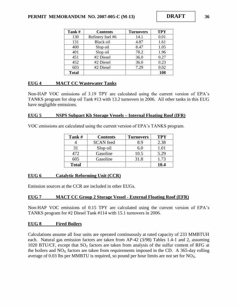
PERMIT MEMORANDUM NO. 2007-005-C (M-13) 36
DRAFT
Tank # Contents Turnovers TPY
130 Refinery fuel #6 14.1 0.01
131 Black oil 4.87 1.61
400 Slop oil 8.47 1.05
401 Slop oil 78.2 1.96
451 #2 Diesel 36.0 0.27
452 #2 Diesel 36.0 0.23
603 #2 Diesel 7.29 0.02
Total 108
EUG 4 MACT CC Wastewater Tanks
Non-HAP VOC emissions of 3.19 TPY are calculated using the current version of EPA‟s
TANKS program for slop oil Tank #13 with 13.2 turnovers in 2006. All other tanks in this EUG
have negligible emissions.
EUG 5 NSPS Subpart Kb Storage Vessels – Internal Floating Roof (IFR)
VOC emissions are calculated using the current version of EPA‟s TANKS program.
Tank # Contents Turnovers TPY
4 SCAN feed 8.9 2.38
31 Slop oil 6.0 1.01
472 Gasoline 10.5 5.29
605 Gasoline 31.8 1.73
Total 10.4
EUG 6 Catalytic Reforming Unit (CCR)
Emission sources at the CCR are included in other EUGs.
EUG 7 MACT CC Group 2 Storage Vessel - External Floating Roof (EFR)
Non-HAP VOC emissions of 0.15 TPY are calculated using the current version of EPA‟s
TANKS program for #2 Diesel Tank #114 with 15.1 turnovers in 2006.
EUG 8 Fired Boilers
Calculations assume all four units are operated continuously at rated capacity of 233 MMBTUH
each. Natural gas emission factors are taken from AP-42 (3/98) Tables 1.4-1 and 2, assuming
1020 BTU/CF, except that SO2 factors are taken from analysis of the sulfur content of RFG at
the boilers and NOX factors are taken from requirements imposed in the CD. A 365-day rolling
average of 0.03 lbs per MMBTU is required, so pound per hour limits are not set for NOX.

PERMIT MEMORANDUM NO. 2007-005-C (M-13) 37
DRAFT
Boiler Emissions
Each Boiler Four Boiler Total
Pollutant Lb/MMCF Lb/hr TPY TPY
NOX 0.03 N/A 30.6 122
CO 84 19.2 84.0 336
PM 7.6 1.74 7.60 30.4
SO2 12.5 2.85 12.5 50.0
VOC 5.5 1.26 5.50 22.0
Emission factors for HAP were also reviewed, using AP-42 (3/98) Table 1.4-3. Only those
factors resulting in 0.01 TPY or more of any constituent are reported here. The following table
shows all of these constituents, picking the higher value when both fuels resulted in emissions of
any single constituent. Emission totals from the 2006 Turn-around document are shown for
comparison. Note that 2006 data for benzene included oil combustion, which has been
discontinued.
Constituent CAS # Emissions (TPY)
Potential 2006
Formaldehyde 50-00-0 0.30 0.21
Hexane 110-54-3 7.20 0.74
Benzene 91-20-3 0.01 0.10
Toluene 108-88-3 0.01 0.25
EUG 9 Fuel-Burning Equipment
Various process heaters share stacks. Stack parameters follow the equipment list. Except for
SO2, natural gas emission factors are taken from AP-42 (3/98) Tables 1.4-1 and 2, assuming
1,020 BTU/CF. Note that actual heating values at certain units may vary widely from the
standard mentioned. Because HRMT is unable to provide exact heat ratings for this equipment,
the following emission estimates would not become more accurate through knowledge of the
precise heating value of the fuel used by each heater. According to the CD, all heaters are
affected facilities under NSPS Subpart J, although a modification to the CD delayed the
compliance date for the CDU heaters until December 31, 2010. An H2S value of 350 ppm was
arbitrarily chosen to evaluate all but the Penex heater, which has an independent permit
condition.
Source Pollutant Emission factor
Lb/MMCF
Emissions
Lb/hr TPY
CDU-
atmospheric
NOX 280 55 240
CO 84 16 72
PM 7.6 1.5 6.5
SO2 59 12 51
VOC 5.5 1.1 4.7
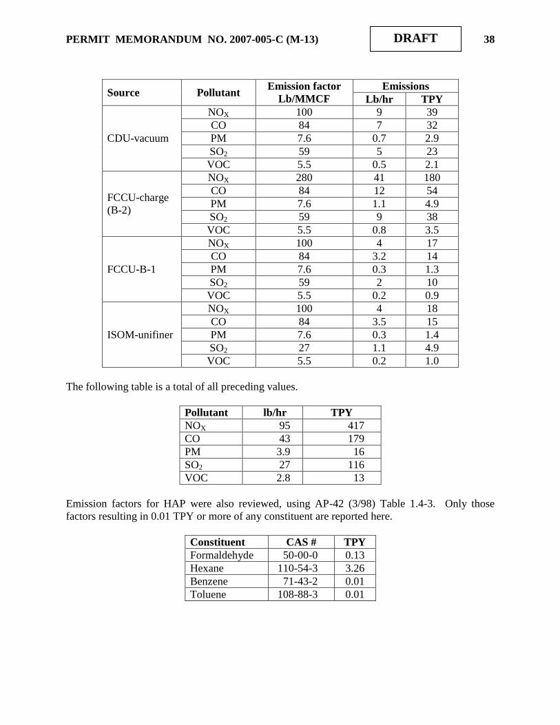
PERMIT MEMORANDUM NO. 2007-005-C (M-13) 38
DRAFT
Source Pollutant Emission factor
Lb/MMCF
Emissions
Lb/hr TPY
CDU-vacuum
NOX 100 9 39
CO 84 7 32
PM 7.6 0.7 2.9
SO2 59 5 23
VOC 5.5 0.5 2.1
FCCU-charge
(B-2)
NOX 280 41 180
CO 84 12 54
PM 7.6 1.1 4.9
SO2 59 9 38
VOC 5.5 0.8 3.5
FCCU-B-1
NOX 100 4 17
CO 84 3.2 14
PM 7.6 0.3 1.3
SO2 59 2 10
VOC 5.5 0.2 0.9
ISOM-unifiner
NOX 100 4 18
CO 84 3.5 15
PM 7.6 0.3 1.4
SO2 27 1.1 4.9
VOC 5.5 0.2 1.0
The following table is a total of all preceding values.
Pollutant lb/hr TPY
NOX 95 417
CO 43 179
PM 3.9 16
SO2 27 116
VOC 2.8 13
Emission factors for HAP were also reviewed, using AP-42 (3/98) Table 1.4-3. Only those
factors resulting in 0.01 TPY or more of any constituent are reported here.
Constituent CAS # TPY
Formaldehyde 50-00-0 0.13
Hexane 110-54-3 3.26
Benzene 71-43-2 0.01
Toluene 108-88-3 0.01
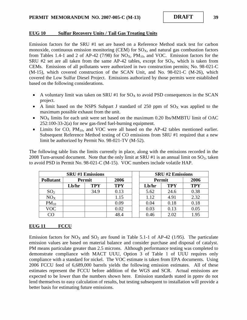
PERMIT MEMORANDUM NO. 2007-005-C (M-13) 39
DRAFT
EUG 10 Sulfur Recovery Units / Tail Gas Treating Units
Emission factors for the SRU #1 set are based on a Reference Method stack test for carbon
monoxide, continuous emission monitoring (CEM) for SOX, and natural gas combustion factors
from Tables 1.4-1 and 2 of AP-42 (7/98) for NOX, PM10, and VOC. Emission factors for the
SRU #2 set are all taken from the same AP-42 tables, except for SOX, which is taken from
CEMs. Emissions of all pollutants were authorized in two construction permits; No. 98-021-C
(M-15), which covered construction of the SCAN Unit, and No. 98-021-C (M-26), which
covered the Low Sulfur Diesel Project. Emissions authorized by those permits were established
based on the following considerations.
A voluntary limit was taken on SRU #1 for SOX to avoid PSD consequences in the SCAN
project.
A limit based on the NSPS Subpart J standard of 250 ppm of SOX was applied to the
maximum possible exhaust from the unit.
NOX limits for each unit were set based on the maximum 0.20 lbs/MMBTU limit of OAC
252:100-33-2(a) for new gas-fired fuel-burning equipment.
Limits for CO, PM10, and VOC were all based on the AP-42 tables mentioned earlier.
Subsequent Reference Method testing of CO emissions from SRU #1 required that a new
limit be authorized by Permit No. 98-021-TV (M-52).
The following table lists the limits currently in place, along with the emissions recorded in the
2008 Turn-around document. Note that the only limit at SRU #1 is an annual limit on SO2, taken
to avoid PSD in Permit No. 98-021-C (M-15). VOC numbers include volatile HAP.
SRU #1 Emissions SRU #2 Emissions
Pollutant Permit 2006 Permit 2006
Lb/hr TPY TPY Lb/hr TPY TPY
SO2 34.9 0.13 5.62 24.6 0.38
NOX 1.15 1.12 4.91 2.32
PM10 0.09 0.04 0.18 0.18
VOC 0.02 0.03 0.13 0.05
CO 48.4 0.46 2.02 1.95
EUG 11 FCCU
Emission factors for NOX and SO2 are found in Table 5.1-1 of AP-42 (1/95). The particulate
emission values are based on material balance and consider purchase and disposal of catalyst.
PM means particulate greater than 2.5 microns. Although performance testing was completed to
demonstrate compliance with MACT UUU, Option 3 of Table 1 of UUU requires only
compliance with a standard for nickel. The VOC estimate is taken from EPA documents. Using
2006 FCCU feed of 6,689,000 barrels yields the following emission estimates. All of these
estimates represent the FCCU before addition of the WGS and SCR. Actual emissions are
expected to be lower than the numbers shown here. Emission standards stated in ppmv do not
lend themselves to easy calculation of results, but testing subsequent to installation will provide a
better basis for estimating future emissions.
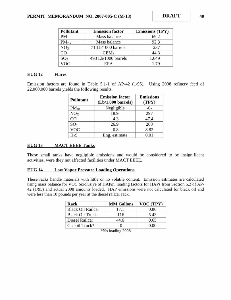
PERMIT MEMORANDUM NO. 2007-005-C (M-13) 40
DRAFT
Pollutant Emission factor Emissions (TPY)
PM Mass balance 69.2
PM2.5 Mass balance 92.3
NOX 71 Lb/1000 barrels 237
CO CEMs 44.3
SO2 493 Lb/1000 barrels 1,649
VOC EPA 1.79
EUG 12 Flares
Emission factors are found in Table 5.1-1 of AP-42 (1/95). Using 2008 refinery feed of
22,060,000 barrels yields the following results.
Pollutant Emission factor
(Lb/1,000 barrels)
Emissions
(TPY)
PM10 Negligible -0-
NOX 18.9 297
CO 4.3 47.4
SO2 26.9 208
VOC 0.8 8.82
H2S Eng. estimate 0.01
EUG 13 MACT EEEE Tanks
These small tanks have negligible emissions and would be considered to be insignificant
activities, were they not affected facilities under MACT EEEE.
EUG 14 Low Vapor Pressure Loading Operations
These racks handle materials with little or no volatile content. Emission estimates are calculated
using mass balance for VOC (exclusive of HAPs), loading factors for HAPs from Section 5.2 of AP-
42 (1/95) and actual 2008 amounts loaded. HAP emissions were not calculated for black oil and
were less than 10 pounds per year at the diesel railcar rack.
Rack MM Gallons VOC (TPY)
Black Oil Railcar 17.1 0.80
Black Oil Truck 116 5.43
Diesel Railcar 44.6 0.65
Gas oil Truck* -0- 0.00 *No loading 2008

PERMIT MEMORANDUM NO. 2007-005-C (M-13) 41
DRAFT
EUG 15 High Vapor Pressure Loading Operations
There are several loading racks that handle VOC materials. Emissions from the butane and
propylene racks are routed to the refinery flare. The terminal propane, gasoline, and diesel racks
are vented to a vapor combustion device. This latter device exhausts at 35 above grade.
Emissions from the propylene rack are calculated in a series of steps that depend on the loading
process itself. The truck is a pressure vessel and the factors of Section 5.2 of AP-42 do not
apply. The only loss consideration is the possible contents of the flexible lines used in the
loading process and the physical state (phase, pressure, etc.) of the contents of these lines. Thus,
a fixed amount of loss may be assigned to each loading event. Total product can be divided by
the capacity of each truck to calculate the number of loading events. Loss per event multiplied
by the number of events yields total emissions. The maximum loading rate of 15,000 gallons per
hour can be used to calculate a maximum hourly emission rate of 6.16 lbs/hr of VOC. The
maximum sustained production rate of 800 barrels per day yields an annual potential of 6.90
TPY. Actual loading of 5.44 MM gallons for 2008 resulted in VOC emissions of 0.75 TPY.
A similar approach was taken in analyzing butane rack emissions except that no maximum rate is
available. Actual loading of 38.7 MM gallons for 2008 resulted in 3. 5 TPY of VOC emissions.
Propane rack loading losses are negligible.
HSR loading rack throughput for 2008 was 6.54 MMgal. Non-HAP VOC emissions were
calculated at 0.185 TPY and HAPs totaled 0.015 TPY.
Terminal loading rack losses are handled as either controlled or uncontrolled. Uncontrolled losses
are based on the 98.7% efficiency attached to the tank trucks, all of which must have pressure
inspection stickers before they may use the facility. This efficiency estimate is found in the
Background Information Document (BID) for the Gasoline Distribution NESHAP promulgated in
November 1994. The BID is published as EPA-453/R-94-002b, and relies on methodology
developed in NSPS Subpart XX (Bulk Gasoline Terminals). The vapor destruction system is
considered to have worst-case emissions at the MACT R threshold of 10 mg/liter, regardless of
material loaded. Loading emission factors are determined by using equation (1) and factors found
in Section 5.2 of AP-42 (1/95). These include S = 0.6 and T = 59.5°F for all cases, M = 60, P =
0.006 for diesel, and M = 64.9, P = 5 for gasoline. Data from the 2008 annual emission inventory
show loading of 48.2 MM gallons of diesel and 131.1 MM gallons of gasoline. The stated
information and assumptions yield less than 0.01 TPY of uncontrolled emissions from diesel
loading, 2.79 TPY of uncontrolled emissions from gasoline loading, and 7.48 TPY of controlled
emissions from total loading.

PERMIT MEMORANDUM NO. 2007-005-C (M-13) 42
DRAFT
EUG 16 Fugitive Emissions
Equipment leaks from the process units and terminal are included in this Group. Piping and
equipment associated with the cooling towers and with the wastewater system are included with
the process units. Over 20,000 items were tabulated in the initial TV permit. There is at least
one construction permit open and several modifications to the operating permit, all of which
have the potential to slightly alter the total. The equipment count was detailed to process units
and further refined to show type of service, such as gas, light liquid, etc., and finally divided as
to components larger or smaller than two inches. Speciation of the VOC was based on testing or
analysis of streams at each of the listed units. Total VOC was estimated at 838 TPY, HAP
included, with the most highly-represented HAPs being hexane at 18.9 TPY, toluene at 18.0
TPY, and MTBE at 12.3 TPY. The turn-around document for 2008 shows 192 TPY of non-HAP
VOC and 8.21 TPY of VHAP. The most highly-represented HAP are hexane at 2.26 TPY,
toluene at 1.99 TPY, and xylene at 1.81 TPY.
The project is expected to add approximately 2,440 new fugitive emission components, as shown
in the following table. Emission factors are taken from the “Protocol for Equipment Leak
Emission Estimates” (EPA-453/R-95-017), using light liquid/gas service data from Table 2-10,
except for flanges/connectors, for which the factor is taken from Table 2-2 of the same reference.
Screening factors for Table 2-10 calculations include 2,000 ppm for pump seals and 500 ppm for
all others. Calculations make the conservatively high assumption that all emissions are VOC,
resulting in an increase of 5.12 TPY of VOC due to the project.
Source # of items Factor
lb/hr/source
Emissions
Lb/hr TPY
Pump seals 20 0.0114 0.23 1.00
Valves 600 0.00052 0.31 1.37
Flanges/connectors 1,600 0.00055 0.88 3.85
Drains 20 0.0175 0.35 1.53
Others 200 0.0001 0.02 0.09
Totals
1.79 7.84
EUG 17 Wastewater System
Emissions are calculated using EPA‟s WATER9 program for estimating air emissions from
wastewater systems, “Air Emission Models Wastewater Treatment.” The model was run using
an outflow of 457,874,200 gallons (871 gpm) and measured concentrations of various
constituents. Results are included in the EUG 16 totals.
EUG 18 Hydrocarbon Recovery System
Non-HAP VOC emissions too small to estimate were calculated using mass balance for the
group of tanks involved, with total throughput of 2,500 gallons in 2008.

PERMIT MEMORANDUM NO. 2007-005-C (M-13) 43
DRAFT
EUG 19 Cooling Towers
Cooling towers are considered to be trivial sources for Title V purposes, because particulate
emissions are larger than 30 microns. Assuming drift to be 1.7 lbs/1,000 gals in these induced
draft systems yields PM emissions of 62.2 TPY. This calculation of VOC PTE is based on
factors found in Table 5.1-2 of AP-42 (1/95), using an aggregate circulation rate of 113,000 gpm.
The 2008 emission inventory report showed entrained non-HAP VOC emissions of 19.4 TPY.
EUG 20 NSPS Kb Tanks (EFR) - MACT CC Group 1 Wastewater
The permit authorizing construction of tanks 474 and 475 established an emission limit of 19.57
TPY of VOC. Tank 476 was estimated to have emissions of 1.90 TPY of VOC, with a
throughput limit of 683 MMgpy. Turnaround document emissions for 2006 follow.
Tank
No.
Throughput,
1,000 gallons
VOC Emissions
(TPY)
474 10,093 2.24
475 14,198 0.28
476 436,175 1.18
EUG 21 Pressurized Spheres
There are no emissions from these pressurized tanks. Fugitive emissions from associated piping
are included in the calculations for EUG 16 above.
EUG 22 Pressurized Bullet Tanks
There are no emissions from these pressurized tanks. Fugitive emissions from associated piping
are included in the calculations for EUG 16 above.
EUG 23 MACT CC Group 2 Wastewater Tanks
There are negligible emissions from the tanks in this EUG.
EUG 24 Tanks Subject to NESHAP FF. There are negligible emissions from the tank in this EUG.
EUGs 25, 26, and 27 Fuel-Burning Equipment
Emissions of particulate (PM10), carbon monoxide (CO), and VOC from all new and existing
equipment are calculated based on factors found in Tables 1.4-1 and 2 of AP-42 (7/98). Oxides of
nitrogen (NOX) for new units and for those units modified with low-NOX burners is estimated
based on vendor performance data. The NOX factor for existing units not modified for such
burners is taken to be the OAC 252:100-33-2(a) limit of 0.20 lbs/MMBTU for new equipment.
This factor differs from the AP-42 factor used in annual emission inventories. The SO2 factor
assumes a maximum concentration of 0.1 grain of H2S per dscf, which is the Subpart J standard,

PERMIT MEMORANDUM NO. 2007-005-C (M-13) 44
DRAFT
and stoichiometric conversion to SO2. All refinery fuel gas (RFG) is assumed to have a heating
value of 1,023 BTU/CF.
EUG 25
Unit and
heat rate
Pollutant
Emission
factor
Emissions
Lbs/hr TPY
NHDS Charge
heater
39 MMBTUH
SO2 0.1 gr/dscf 1.03 4.49
NOX 0.05 lb/MMBTU 4.95 8.54
PM10 7.6 lb/MMCF 0.29 1.27
VOC 5.5 lb/MMCF 0.21 0.92
CO 84 lb/MMCF 3.21 14.1
NHDS Stripper
reboiler
44.2 MMBTUH
SO2 0.1 gr/dscf 1.16 5.09
NOX 0.05 lb/MMBTU 2.21 9.68
PM10 7.6 lb/MMCF 0.33 1.44
VOC 5.5 lb/MMCF 0.24 1.04
CO 84 lb/MMCF 3.64 15.9
SCAN charge
heater
25.2 MMBTUH
SO2 0.1 gr/dscf 0.68 2.97
NOX 0.07 lb/MMBTU 1.76 7.73
PM10 7.6 lb/MMCF 0.19 0.82
VOC 5.5 lb/MMCF 0.14 0.60
CO 84 lb/MMCF 2.08 9.09
EUG 26
Unit and
heat rate
Pollutant
Emission
factor
Emissions
Lbs/hr TPY
CCR
Interheater #1
141.8 MMBTUH
SO2 0.1 gr/dscf 3.73 16.3
NOX 0.05 lb/MMBTU 7.09 31.1
PM10 7.6 lb/MMCF 1.06 4.63
VOC 5.5 lb/MMCF 0.76 3.35
CO 84 lb/MMCF 11.7 51.1
EUG 27
Unit and
heat rate
Pollutant
Emission
factor
Emissions
Lbs/hr TPY
CCR Charge
heater
120 MMBTUH
SO2 0.1 gr/dscf 3.15 13.8
NOX 0.05 lb/MMBTU 6.00 26.3
PM10 7.6 lb/MMCF 0.89 3.92
VOC 5.5 lb/MMCF 0.65 2.83
CO 84 lb/MMCF 9.88 43.3
CCR
Interheater #2
101 MMBTUH
SO2 0.1 gr/dscf 2.65 11.6
NOX 0.20 lb/MMBTU 20.2 88.5
PM10 7.6 lb/MMCF 0.75 3.30
VOC 5.5 lb/MMCF 0.54 2.39
CO 84 lb/MMCF 8.32 36.4

PERMIT MEMORANDUM NO. 2007-005-C (M-13) 45
DRAFT
Unit and
heat rate
Pollutant
Emission
factor
Emissions
Lbs/hr TPY
CCR
Interheater #2
25 MMBTUH
SO2 0.1 gr/dscf 0.66 2.88
NOX 0.20 lb/MMBTU 5.00 21.9
PM10 7.6 lb/MMCF 0.19 0.82
VOC 5.5 lb/MMCF 0.13 0.59
CO 84 lb/MMCF 2.06 9.02
CCR Stabilizer
reboiler
85 MMBTUH
SO2 0.1 gr/dscf 2.23 9.79
NOX 0.05 lb/MMBTU 4.25 18.6
PM10 7.6 lb/MMCF 0.63 2.77
VOC 5.5 lb/MMCF 0.46 2.01
CO 84 lb/MMCF 7.00 30.7
DHTU Charge
heater
55 MMBTUH
SO2 0.1 gr/dscf 1.45 6.33
NOX 0.20 lb/MMBTU 11.0 48.2
PM10 7.6 lb/MMCF 0.41 1.79
VOC 5.5 lb/MMCF 0.30 1.30
CO 84 lb/MMCF 4.53 19.8
BenZap Splitter
NOX 40 3.0 13.1
CO 84 6.3 17.6
PM 7.6 0.6 2.5
SO2 27 2.0 8.9
VOC 5.5 0.4 1.8
Facility-wide Emission Totals
The following table summarized all of the estimated individual EUG emission amounts as they
existed in the original renewal. Note that only those numbers arising from equipment with
clearly stated capacities or ratings can be assumed to represent maximum emissions. All other
data represented the refinery as it operated in 2006. There is very little information available as
to “design” capacity of any Unit, because refining is an evolutionary process, with more efficient
use of existing equipment allowing greater throughput. Review the design capacity discussion in
Section II for further details.
CRITERIA POLLUTANTS
Pollutant TPY
NOX 2,434
CO 923
SO2 3,072
PM 313
Non-HAP VOC 588
The following table of HAP emissions is taken from the 2006 Turnaround document and is not an
attempt to analyze potential to emit for any pollutant.
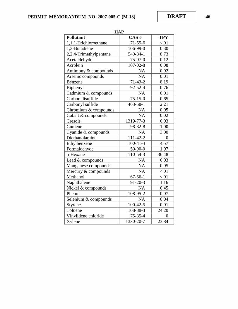
PERMIT MEMORANDUM NO. 2007-005-C (M-13) 46
DRAFT
HAP
Pollutant CAS # TPY
1,1,1-Trichloroethane 71-55-6 <.01
1,3-Butadiene 106-99-0 0.30
2,2,4-Trimethylpentane 540-84-1 8.73
Acetaldehyde 75-07-0 0.12
Acrolein 107-02-8 0.08
Antimony & compounds NA 0.02
Arsenic compounds NA 0.01
Benzene 71-43-2 8.19
Biphenyl 92-52-4 0.76
Cadmium & compounds NA 0.01
Carbon disulfide 75-15-0 0.65
Carbonyl sulfide 463-58-1 2.21
Chromium & compounds NA 0.05
Cobalt & compounds NA 0.02
Cresols 1319-77-3 0.03
Cumene 98-82-8 1.00
Cyanide & compounds NA 3.00
Diethanolamine 111-42-2 0
Ethylbenzene 100-41-4 4.57
Formaldehyde 50-00-0 1.97
n-Hexane 110-54-3 36.48
Lead & compounds NA 0.03
Manganese compounds NA 0.05
Mercury & compounds NA <.01
Methanol 67-56-1 <.01
Naphthalene 91-20-3 11.16
Nickel & compounds NA 0.45
Phenol 108-95-2 0.07
Selenium & compounds NA 0.04
Styrene 100-42-5 0.01
Toluene 108-88-3 24.20
Vinylidene chloride 75-35-4 0
Xylene 1330-20-7 23.84

PERMIT MEMORANDUM NO. 2007-005-C (M-13) 47
DRAFT
V. INSIGNIFICANT ACTIVITIES
The insignificant activities identified and justified on Part 1b of the forms in the application and
duplicated below were confirmed by the initial operating permit inspection. Records are
available that confirm the insignificance of the activities. Appropriate recordkeeping is required
for those activities indicated below with an asterisk. HRMT has included some activities that are
not present at the refinery but that may be required in the future. For instance, wood chipping is
not currently performed but could be required on a temporary basis in the event that a tornado
destroyed large numbers of trees on refinery property.
Space heaters, boilers, process heaters, and emergency flares less than or equal to 5 MMBTUH
heat input (commercial natural gas).
Emissions from stationary internal combustion engines rated less than 50 HP output.
Emissions from gas turbines with less than 215 KW rating of electric output.
*Emissions from fuel storage/dispensing equipment operated solely for facility-owned vehicles if
fuel throughput is not more than 2,175 gallons per day (gpd), including dispensing, averaged
over a 30-day period. During 2008, HRMT dispensed 61,400 gallons of gasoline from Tank 419
(168 gpd) and 63,400 gallons of diesel from Tank 420 (174 gpd) solely for facility-owned
vehicles. EUG 3 Tank 603 in the bulk loading terminal area dispensed 674,200 gallons to refuel
diesel trucks (1,847 gpd).
Fixed Roof Tanks
Tank
No.
Point
ID
Year
Built Height Diameter
Nominal
Capacity
419 22635 1976 6' 11' 70 Bbl
420 22634 1976 6' 11' 70 Bbl
*Storage tanks with less than or equal to 10,000 gallons capacity that store volatile organic
liquids with a true vapor pressure less than or equal to 1.0 psia at maximum storage temperature.
Gasoline, diesel fuel, aircraft fuel, and fuel oil handling facilities, equipment and storage tanks
except those subject to NSPS and standards in OAC 252:100-37-15, 39-30, 39-41, and 39-48, or
with a capacity greater than 400 gallons.
*Emissions from storage tanks constructed with a capacity less than 39,894 gallons that store
VOC with a vapor pressure less than 1.5 psia at maximum storage temperature.
Additions or upgrades of instrumentation or control systems that result in emissions increases
less than the pollutant quantities specified in OAC 252:100-8-3(e)(1).
Welding and soldering operations utilizing less than 100 pounds of solder and 53 tons per year of
electrodes. Any welding or soldering is for maintenance purposes only, and is thus a Trivial
activity.

PERMIT MEMORANDUM NO. 2007-005-C (M-13) 48
DRAFT
Wood chipping operations not associated with the primary process operation.
Torch cutting and welding of under 200,000 tons of steel fabricated. Any such activity is for
maintenance purposes only, and is thus a Trivial activity.
Site restoration and/or bioremediation activities of less than 5 years duration.
Hydrocarbon contaminated soil aeration pads utilized for soils excavated at the facility only.
Emissions from the operation of groundwater remediation wells including but not limited to
emissions from venting, pumping, and collecting activities subject to de minimis limits for air
toxics (OAC 252:100-42) and HAP (§112(b) of CAAA ‟90).
*Non-commercial water washing operations (less than 2,250 barrels per year) and drum crushing
operations of empty barrels less than or equal to 55 gallons with less than three percent by
volume of residual material.
Hazardous waste and hazardous materials drum staging areas.
Sanitary sewage collection and treatment facilities other than incinerators and POTW. Stacks or
vents for sanitary sewer plumbing traps are also included (i.e., lift station).
Emissions from landfills and land farms unless otherwise regulated by an applicable state or
federal regulation.
Exhaust systems for chemical, paint, and/or solvent storage rooms or cabinets, including
hazardous waste satellite (accumulation) areas.
The applicant listed numerous activities in its application for the initial TV permit. Some were
dismissed as Trivial and some could not be Insignificant because they were subject to various
rules and regulations. The non-trivial activities are listed below, but with descriptions of their
applicability that are much shorter than that given in the initial Memorandum. Headings are
repeated as offered in the original application.
Laboratory
Applicant estimates emission of VOC from laboratory vent hoods to be well below 5 TPY.
Maintenance: Equipment and Piping
Maintenance of lines, pipes, and valves with the emission of VOC may be considered
Insignificant only if the VOC emissions result from external cleaning or coating of the
equipment. Maintenance associated in any way with the LDAR program is a regulated activity
and cannot be Insignificant.

PERMIT MEMORANDUM NO. 2007-005-C (M-13) 49
DRAFT
Maintenance: Miscellaneous
Parts cleaning with the emission of VOC. Appendix I allows “Hand wiping and spraying of
solvents from containers with less than 1 liter capacity used for spot cleaning and/or degreasing
in ozone attainment areas” as an Insignificant activity. OAC 252:100-39-42 controls the design
and operation of both cold (§a) and vapor (§b and §c) degreasers in Tulsa County. Further,
degreasers may be subject to NESHAP MACT Subpart T. Degreasers affected by these state or
federal requirements cannot be considered Insignificant activities.
Operations: Miscellaneous
Backup fuel fired pumps, compressors, or other machines with the emission of SOX, NOX, CO,
CO2, VOC, and particulates. Such equipment is included in Appendix I and may require record-
keeping. For instance, stationary internal combustion engines rated less than 50 hp output do not
require records, but stationary reciprocating engines used exclusively for emergency power
generation or for peaking power service shall not exceed 500 hours of use per year.
The loading, unloading, and screening of catalyst and/or support materials with the emission of
particulates. Some catalyst may be toxic, with the potential to cause harm. Therefore, DEQ
agrees that this should be included as an Insignificant activity and requires that records be
maintained for each such transfer and screening event. Such records shall include the type and
amount of material handled, applicant‟s engineering estimate of losses, and the method of
calculation.
VI. OKLAHOMA AIR POLLUTION CONTROL RULES
OAC 252:100-1 (General Provisions) [Applicable]
Subchapter 1 includes definitions but there are no regulatory requirements.
OAC 252:100-2 (Incorporation by Reference) [Applicable]
This subchapter incorporates by reference applicable provisions of Title 40 of the Code of
Federal Regulations listed in OAC 252:100, Appendix Q. These requirements are addressed in
the “Federal Regulations” section.
OAC 252:100-3 (Air Quality Standards and Increments) [Applicable]
Subchapter 3 enumerates the primary and secondary ambient air quality standards and the
significant deterioration increments. At this time, all of Oklahoma is in “attainment” of these
standards.
OAC 252:100-5 (Registration, Emissions Inventory and Annual Operating Fees) [Applicable]
Subchapter 5 requires sources of air contaminants to register with Air Quality, file emission
inventories annually, and pay annual operating fees based upon total annual emissions of
regulated pollutants. Emission inventories were submitted and fees paid for previous years as
required.

PERMIT MEMORANDUM NO. 2007-005-C (M-13) 50
DRAFT
OAC 252:100-8 (Permits for Part 70 Sources) [Applicable]
Part 5 includes the general administrative requirements for Part 70 permits. Any planned
changes in the operation of the facility that result in emissions not authorized in the permit and
that exceed the “Insignificant Activities” or “Trivial Activities” thresholds require prior
notification to AQD and may require a permit modification. Insignificant activities refer to those
individual emission units either listed in Appendix I or whose actual calendar year emissions do
not exceed the following limits.
5 TPY of any one criteria pollutant
2 TPY of any one hazardous air pollutant (HAP) or 5 TPY of multiple HAP or 20%
of any threshold less than 10 TPY for a HAP that the EPA may establish by rule
Emission limitations and operational requirements necessary to assure compliance with all other
applicable requirements for all sources are taken from the initial TV permit, from the various
modifications based on the initial TV permit, from the TVR and construction permit
applications, Civil Action No. 08-CV 020-D, or are developed from the applicable requirement.
OAC 252:100-9 (Excess Emissions Reporting Requirements) [Applicable]
Except as provided in OAC 252:100-9-7(a)(1), the owner or operator of a source of excess
emissions shall notify the Director as soon as possible but no later than 4:30 p.m. the following
working day of the first occurrence of excess emissions in each excess emission event. No later
than thirty (30) calendar days after the start of any excess emission event, the owner or operator
of an air contaminant source from which excess emissions have occurred shall submit a report
for each excess emission event describing the extent of the event and the actions taken by the
owner or operator of the facility in response to this event. Request for affirmative defense, as
described in OAC 252:100-9-8, shall be included in the excess emission event report. Additional
reporting may be required in the case of ongoing emission events and in the case of excess
emissions reporting required by 40 CFR Parts 60, 61, or 63.
OAC 252:100-13 (Open Burning) [Applicable]
Open burning of refuse and other combustible material is prohibited except as authorized in the
specific examples and under the conditions listed in this subchapter.
OAC 252:100-19 (Particulate Matter (PM)) [Applicable]
Section 19-4 regulates emissions of PM from new and existing fuel-burning equipment, with
emission limits based on maximum design heat input rating. Appendix C specifies PM emission
limitations for all equipment at this facility. Fuel-burning equipment is defined in OAC
252:100-19 as any internal combustion engine or gas turbine, or other combustion device used to
convert the combustion of fuel into usable energy. The flares of EUG-12 and at the terminal are
not pieces of fuel-burning equipment under the state definition and are not affected by this rule.
All fuel-burning equipment uses gaseous fuel. AP-42 (7/98) Table 1.4-2 lists natural gas total
PM emissions to be 7.6 lbs/million scf or about 0.0076 lbs/MMBTU, which is in compliance.
The following equipment is subject to the requirements of this subchapter.

PERMIT MEMORANDUM NO. 2007-005-C (M-13) 51
DRAFT
Equipment Maximum Heat
Input (MMBTUH)
Emissions (Lbs/MMBTU)
Appendix C Potential Rate
Boilers 1, 2, 3, 4 233 each 0.28 0.008
CDU atmospheric heater 200 0.29 0.008
CDU vacuum heater 90 0.36 0.008
FCCU B-2 heater 150 0.32 0.008
FCCU B-1 heater 38.4 0.44 0.008
Unifiner H-1 heater 42 0.43 0.008
TGTU #2 12.1 0.58 0.008
SCAN charge heater 25.2 0.48 0.008
NHDS charge heater 39 0.44 0.008
NHDS stripper/reboiler 44.2 0.42 0.008
CCR interheater #1 141.8 0.32 0.008
DHTU charge heater 55 0.40 0.008
CCR charge heater 120 0.33 0.008
CCR interheater #2-1 101 0.35 0.008
CCR interheater #2-2 25 0.48 0.008
CCR stabilizer/reboiler 85 0.36 0.008
BenZap reboiler 75 0.37 0.008
Section 19-12 sets limits on particulate emissions from any new or existing industrial process. The
facility had 2006 emissions of 319 TPY of PM10 (excluding cooling tower emissions), as shown in
Section IV. Data supplied during the initial permit process suggest that 293 pounds per barrel is a
reasonable average for crude at the CDU. Assuming continuous operation, the crude portion of the
process rate is 400 TPH. Catalyst circulates at a rate of 16-18 tons per minute, or a minimum of
960 TPH. The total process weight rate exceeds 1,360 TPH. Appendix G allows an emission rate
of 81.6 lbs/hr for this process rate, or 358 TPY. This is larger than the reported emissions, and the
facility is in compliance. The June 30, 2008 CD requires that particulate emissions from the
FCCU regenerator not exceed the Subpart J standard of 1.0 lbs/ton of coke burnoff. The limit set
by Appendix G depends on process throughput, which cannot be directly related to the catalyst
throughput of 16 – 18 TPH. Thus, addition of the Subpart J standard does not alter compliance
with Section 19-12.
OAC 252:100-25 (Visible Emissions and Particulates) [Applicable]
No discharge of greater than 20% opacity is allowed except for short-term occurrences that
consist of not more than one six-minute period in any consecutive 60 minutes, not to exceed
three such periods in any consecutive 24 hours. In no case shall the average of any six-minute
period exceed 60% opacity. The flares are potential sources of visible emissions at this facility.
Proper operation of the smokeless flares should maintain compliance.

PERMIT MEMORANDUM NO. 2007-005-C (M-13) 52
DRAFT
Subsection 25-5(a) requires continuous monitoring of opacity at the FCCU catalyst regenerator.
The monitoring system is in place and has met all requirements. The June 30, 2008 CD required
compliance with the opacity standard of NSPS Subpart J no later than June 30, 2008. According
to §25-5(c), sources required to comply with an opacity standard are exempt from §25-5(a), thus
the regenerator is no longer subject to Subchapter 25. This subsection also applies to fossil-
fueled steam generators with heat input greater than 250 MMBTUH. None of the refinery
equipment meets this threshold.
OAC 252:100-29 (Fugitive Dust) [Applicable]
No person shall cause or permit the discharge of any visible fugitive dust emissions beyond the
property line on which the emissions originate in such a manner as to damage or to interfere with
the use of adjacent properties, or cause air quality standards to be exceeded, or interfere with the
maintenance of air quality standards. Heavy traffic areas, including the racks and the offices, are
paved. Vehicular traffic in the unpaved areas is greatly restricted for safety reasons. Under normal
operating conditions, this facility will not cause fugitive dust problems, therefore it is not necessary
to require specific precautions to be taken.
OAC 252:100-31 (Sulfur Compounds) [Applicable]
Part 2 lists maximum SO2 ambient air concentration limits of 1,300 g/m3 for a 5-minute period,
1,200 g/m3 (1-hour average), 650 g/m
3 (3-hour average), 130 g/m
3 (24-hour average), and 80
g/m3 (annual average), for existing equipment. Screen3 analysis was performed in the initial
TV Memorandum for all emission points using RFG or liquid fuel. Screen3 one-hour ground
level concentrations are subject to transform factors of 0.9 for three-hour averages, 0.4 for 24-
hour averages, and 0.08 for annual averages. A table in the referenced Memo listed input
parameters and one-hour averages only. Because liquid fuel is no longer used at the BoHo,
further discussion of the analysis with respect to fuel oil in not necessary. Note that the analysis
performed for the B-1 heater is rather hypothetical. It is used for less than 100 hours after three
to four years of inactivity and the flow rate and temperature are educated guesses. Because of its
low usage, these results probably have little significance. RFG was assumed to have little effect
under the standards of Subchapter 31. In addition, installation of a wet scrubber on the FCCU
should result in dramatic reductions of SO2 emissions, reducing ambient impacts from previous
levels.
The initial TV Memorandum contained a table of modeling results that will not be repeated here
for two reasons. First, the table demonstrated compliance and is available for further review, if
desired. Second, two construction projects, SCAN and Low Sulfur Diesel, reduce the amount of
sulfur available to all fuel-burning units by large amounts, so repeating the exercise would yield
even lower results that imply compliance by an even wider margin. Several new sources were
added by the two construction projects and the analysis is available in the Memorandum
associated with Permit No. 98-021-C (M-26).
Emissions of SO2 represent the fairly efficient combustion of H2S. Assuming only 90%
conversion and comparing molecular weights of the two compounds suggests that the highest 24-
hour impact that H2S is capable of causing at the property line is based on a value determined in
the earlier analysis for the CCR, or approximately 1.26 g/m3 (10%/90%) (34/64) = 0.07
g/m3. The subchapter standard of 0.2 ppm converts to approximately 280 g/m
3, so
compliance is demonstrated for all sources.

PERMIT MEMORANDUM NO. 2007-005-C (M-13) 53
DRAFT
Part 5 covers new equipment standards.
In particular, section 31-25 addresses sulfur oxides. New gas fuel-burning equipment, such as
the process heaters of EUG 25 or the modified process heaters of EUG 9, must meet a standard
of 0.2 lbs of SO2 per MMBTU, three-hour average, per §25(a)(1). Because a permit condition
limits H2S content of the RFG to 0.1 gr/dscm, stoichiometric conversion of all H2S to SO2 would
yield emissions of 0.027 lbs/MMBTU, well within the limit set forth. Emission monitoring, fuel
monitoring, and recordkeeping standards are set in §25(c)(2), but apply to only those items rated
at 250 MMBTUH or greater.
Section 31-26(a)(1) covers hydrogen sulfide, setting requirements on the removal efficiency and
emission rates for H2S. The new process units added by the two construction projects mentioned
above must meet this standard. All streams containing H2S are routed to the SRU, whose
efficiency at H2S conversion meets the standard set in §26(a)(1). Using John Zink Company‟s
estimate of incinerator performance (scaled to the expected 25 LTD throughput) yields 0.14
lbs/hr of H2S emissions. Noting that H2S input to the incinerator is 82.7 lbs/hr, the efficiency is
calculated to be 99.8%, well above the 95% minimum requirement of this section. An emission
rate of 0.14 lbs/hr is sufficient to qualify the unit for exemption from the efficiency criterion,
because it is well below the 0.3 lbs/hr threshold value.
Section 31-26(a)(2) covers SO2 recovery standards for the SRUs. Specifically, the two SRUs,
rated at 25 LTD, are covered by the standard described in subparagraph D. The SO2 reduction
efficiency requirement for any SRU is defined by the equation Z = 92.34 X0.00774
, where Z is
the required efficiency and X is the throughput in LTD. For these SRUs, the result is 94.7%.
According to the analysis performed for SRU #1 in Permit No. 98-021-C (M-15), the average
emissions of SO2 are slightly less than 8 lbs/hr. Converting 25 LTD of sulfur to SO2 equivalent
yields an input of 4,667 lbs/hr. The calculated efficiency for SRU #1 is 99.8%, well above the
94.7% threshold. A similar calculation for SRU #2 uses the expected emission rate of 5.6 lbs/hr
of SO2 supplied in the permit application to calculate an efficiency of 99.8%. This number is
also well above the acceptable minimum value. Finally, note that both SRUs have emissions of
SO2 well below the 100 lbs/hr threshold necessary to qualify for exemption from the efficiency
criteria. Thus, 31-26(a)(2) is not applicable.
OAC 252:100-33 (Nitrogen Oxides) [Applicable]
This subchapter limits new gas-fired and liquid-fired fuel-burning equipment with rated heat
input greater than or equal to 50 MMBTUH to emissions of 0.20 and 0.30 lbs of NOX per
MMBTU, three-hour average, respectively. Most fuel-burning equipment was installed prior to
the effective date of this rule, has not been altered in a manner increasing emissions, and is not
subject. The CCR #1 Interheater of EUG 26 is rated at 141.8 MMBTUH and fits this
subchapter‟s definition of “new.” It has a federally-enforceable limit of 0.05 lbs/MMBTU. The
heaters of EUG 27 have accepted federally-enforceable limits on NOX emissions, but
modifications performed on them, such as low-NOX burners, did not have the effect of increasing
NOX emissions, so they are not affected by this subchapter. EUG 27 heaters with input rating
greater than 50 MMBTUH are shown in the following table with the limits they have accepted.

PERMIT MEMORANDUM NO. 2007-005-C (M-13) 54
DRAFT
Heater MMBTUH Input Limit Accepted
DHTU Reactor Charge 55 0.20 lbs/MMBTU
CCR Charge 120 0.05 lbs/MMBTU
CCR #2-1 Interheater 101 0.20 lbs/MMBTU
CCR Stabilizer/Reboiler 85 0.05 lbs/MMBTU
BenZap Reboiler 75 0.04 lbs/MMBTU
OAC 252:100-35 (Carbon Monoxide) [Not Applicable]
The catalytic cracking unit and catalytic reforming unit are existing sources, but are not subject
to the standards of Paragraph 35-2(a) because Tulsa County is not a non-attainment area for
carbon monoxide. If sufficient modifications were performed to either unit that they might
become affected sources, they would meet the new source standards of 35-2(b) because both
have complete secondary combustion systems. The FCCU has a monitor to establish that excess
oxygen is present in the flue gas. The CRU uses a portable analyzer that establishes that excess
oxygen is present at various points in the system. This monitoring is not an OAC 252:100
requirement, and would become so only under the reconstruction or modification situation
outlined above. Conversion of the CRU to a CCR under the Low Sulfur Diesel Project covered
by Permit No. 98-021-C (M-26) was not sufficient to make this a “new” source, but it meets the
new source standards of 35-2(b) because compliance with the standards of 40 CFR 63 Subpart
UUU satisfies the requirements of this subchapter.
OAC 252:100-37 (Volatile Organic Compounds) [Parts 3 & 7 Applicable]
Part 3 concerns the control of volatile organic compounds.
Section 37-15 (a) requires that all storage tanks with capacity greater than 40,000 gallons and
storing a VOC with a vapor pressure greater than 1.5 psia shall be pressure vessels or shall be
equipped with one of the following vapor-loss control devices.
(1) They shall be of EFR or fixed roof with IFR design, with the roof floating on the liquid
surface at all times and equipped with a closure seal between the roof edge and the tank wall.
Floating roofs are not suitable control for liquids with vapor pressure greater than 11.1 psia.
All gauging and sampling devices shall be gas-tight except when gauging or sampling is
taking place.
(2) They shall have an 85% efficient vapor recovery system and a vapor disposal system. All
gauging and sampling devices shall be gas-tight except when gauging or sampling is taking
place.
(3) They shall have other equipment or methods with efficiency at least equal to those
devices listed above.
All of the tanks in EUG 1 have capacities greater than 40,000 gallons and are of IFR design.
Although they do not all store VOC with vapor pressure greater than 1.5 psia, they satisfy the
requirements of this section for doing so.
All of the tanks in EUG 2 have capacities greater than 40,000 gallons and are of EFR design.
Although they may not always store VOC with vapor pressure greater than 1.5 psia, they satisfy
the requirements of this section for doing so.
Many of the tanks in EUG 3 have capacities greater than 40,000 gallons, but none of them stores
liquid with vapor pressure greater than or equal to 1.5 psia. All of these tanks are exempt from
the provisions of Section 37-15 per §37-4(a).
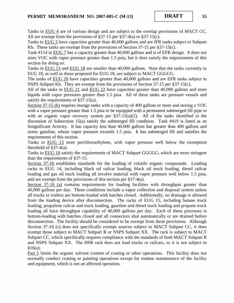
PERMIT MEMORANDUM NO. 2007-005-C (M-13) 55
DRAFT
Tanks in EUG 4 are of various design and are subject to the overlap provisions of MACT CC.
All are exempt from the provisions of §37-15 per §37-4(a) or §37-15(c).
Tanks in EUG 5 have capacities greater than 40,000 gallons and are IFR tanks subject to Subpart
Kb. These tanks are exempt from the provisions of Section 37-15 per §37-15(c).
Tank #114 in EUG 7 has a capacity greater than 40,000 gallons and is of EFR design. It does not
store VOC with vapor pressure greater than 1.5 psia, but it does satisfy the requirements of this
section for doing so.
Tanks in EUG 13 and EUG 18 are smaller than 40,000 gallons. Note that the tanks currently in
EUG 18, as well as those proposed for EUG 18, are subject to MACT GGGGG.
The tanks of EUG 20 have capacities greater than 40,000 gallons and are EFR tanks subject to
NSPS Subpart Kb. They are exempt from the provisions of Section 37-15 per §37-15(c).
All of the tanks in EUG 21 and EUG 22 have capacities greater than 40,000 gallons and store
liquids with vapor pressures greater than 1.5 psia. All of these tanks are pressure vessels and
satisfy the requirements of §37-15(a).
Section 37-15 (b) requires storage tanks with a capacity of 400 gallons or more and storing a VOC
with a vapor pressure greater than 1.5 psia to be equipped with a permanent submerged fill pipe or
with an organic vapor recovery system per §37-15(a)(2). All of the tanks identified in the
discussion of Subsection 15(a) satisfy the submerged fill condition. Tank #419 is listed as an
Insignificant Activity. It has capacity less than 40,000 gallons but greater than 400 gallons and
stores gasoline, whose vapor pressure exceeds 1.5 psia. It has submerged fill and satisfies the
requirements of this section.
Tanks in EUG 13 store perchloroethylene, with vapor pressure well below the exemption
threshold of §37-4(a).
Tanks in EUG 18 satisfy the requirements of MACT Subpart GGGGG, which are more stringent
than the requirements of §37-15.
Section 37-16 establishes standards for the loading of volatile organic compounds. Loading
racks in EUG 14, including black oil railcar loading, black oil truck loading, diesel railcar
loading and gas oil truck loading all involve material with vapor pressure well below 1.5 psia,
and are exempt from the provisions of this section per §37-4(a).
Section 37-16 (a) contains requirements for loading facilities with throughput greater than
40,000 gallons per day. These conditions include a vapor collection and disposal system unless
all trucks or trailers are bottom-loaded with hatches closed. Additionally, no drainage is allowed
from the loading device after disconnection. The racks of EUG 15, including butane truck
loading, propylene railcar and truck loading, gasoline and diesel truck loading and propane truck
loading all have throughput capability of 40,000 gallons per day. Each of these processes is
bottom-loading with hatches closed and all connectors shut automatically or are drained before
disconnection. The facility should be considered to be exempt from these provisions. Although
Section 37-16 (c) does not specifically exempt sources subject to MACT Subpart CC, it does
exempt those subject to MACT Subpart R or NSPS Subpart XX. The rack is subject to MACT
Subpart CC, which specifically requires compliance with the standards of both MACT Subpart R
and NSPS Subpart XX. The HSR rack does not load trucks or railcars, so it is not subject to
§16(a).
Part 5 limits the organic solvent content of coating or other operations. This facility does not
normally conduct coating or painting operations except for routine maintenance of the facility
and equipment, which is not an affected operation.

PERMIT MEMORANDUM NO. 2007-005-C (M-13) 56
DRAFT
Part 7 regulates specific processes.
Section 37-36 requires fuel-burning equipment to be operated and maintained so as to minimize
emissions. The flares of EUG 12 and EUG 15 are not considered to be fuel-burning equipment
and are not affected sources. The boilers of EUG 8, the process heaters of EUGs 9, 25, 26, and
27, and the TGTUs of EUG 10 are affected sources. Proper maintenance and operation to
provide essentially complete combustion provide compliance.
Section 37-37 concerns water separators that receive water containing more than 200 gallons per
day of VOC. The only equipment that may be affected by this section are the “API separators”
at the WWTP and Tanks 474 and 475 of EUG 20, designed for storage of off-test water at the
WWTP. These EFR tanks are subject to NSPS Subpart Kb and compliance with the
requirements of 40 CFR 60.112b(a)(2) satisfies the requirements of OAC 252:100-37-37(2).
However, the section is not applicable to either of these situations because testing of the effluent
has shown it to involve material with vapor pressure well below 1.5 psia, leaving both exempt
from the provisions of this section per §37-4(a).
OAC 252:100-39 (VOC in Non-attainment Areas) [Applicable]
Part 3 affects petroleum refinery operations.
Section 39-15 concerns petroleum refinery equipment leaks and is frequently referred to as
LDAR, for Leak Detection and Reporting. It applies to all components that might have leaks of
VOC when tested by EPA Reference Method (RM) 21 as found in the NSPS regulations of 40
CFR 60. For the purposes of this section, VOC with vapor pressure less than 0.0435 psia is
exempt. Standards and operating procedures are set out in §39-15(c), as summarized following.
1) Monitor per Section (f), record leaking components and tag each component. Repair and
retest leaking components and identify those that cannot be repaired until turnaround. Seal all
lines ending with a valve with a second valve, flange, plug, or cap.
2) AQD may require remedial action based on the number and severity of tagged components
awaiting repair.
3) Pipeline and pressure relief valves shall be marked in a manner obvious to both
monitoring and DEQ personnel.
Monitoring requirements are found in §39-15(f), as summarized following.
1) Monitoring shall consist of annual RM 21 testing for pump seals, pipeline valves in liquid
service, and drains, quarterly RM 21 testing for compressor seals and for pipeline valves and
pressure relief valves in gas service, and weekly visual monitoring for all pump seals.
Further, monitoring shall occur within 24 hours for any pump seal from which VOC liquids
are observed dripping and for any relief valve that has vented to the atmosphere. Any
leaking component shall be monitored immediately after repair.
2) Vapor recovery devices, inaccessible valves, storage tank valves, valves not externally
regulated, and pressure relief devices connected to a flare header are exempt from (1)
provided that inaccessible valves will be monitored during turnarounds.
3) Any leaking component not immediately repaired shall have a readily visible dated
identifying tag attached until it is repaired.
Record keeping and reporting requirements are identified in §39-15(g) and (h), and will be more
fully enumerated in the Specific Conditions of the permit. The facility states that it is in
compliance with all of the requirements listed above.

PERMIT MEMORANDUM NO. 2007-005-C (M-13) 57
DRAFT
Section 39-16 concerns petroleum refinery process unit turnarounds and outlines procedures to
be used during the planned shutdown, inspection, repair, and restart of a unit. VOC in the unit
shall be routed to a flare or vapor recovery system until the unit is blown down to pressure
compatible with the control device pressure. The system may then be purged using appropriate
materials. The unit may not be vented to atmosphere until unit pressure is less than 5 psig. VOC
may not be emitted to the atmosphere through any control device unless it is burned in a
smokeless flare or equivalent device, except for special circumstances. Written notice of the unit
to be shut down, the date of shut down and the amount of VOC emissions anticipated shall be
provided to AQD at least 15 days in advance. Scheduled turnarounds may be exempted from the
control requirements during non-oxidant season if the required notice makes a specific request to
that effect. The facility has provided the appropriate notices for past turnarounds and is in
compliance.
Section 39-17 concerns non-condensable VOC emitted from equipment used in producing
vacuums. Only the vacuum tower at the CDU is affected by this section.
Section 39-17(b) requires that non-condensable VOC from steam ejectors with barometric
condensers, steam ejectors with surface condensers, and mechanical vacuum pumps shall be
incinerated or reduced by 90% through other means. As mentioned in the Process Description,
the vacuum tower has steam ejectors with surface condensers. Vacuum tower overhead enters a
four-stage ejector system. Discharge from the first three ejectors is sent to water-cooled surface
condensers. Under normal operations, discharge from the fourth ejector is sent to the FCCU
“wet gas” compressor known as J-50. That gas is then treated at the FCCU amine treater and
sent to RFG. In the event that J-50 is not operating, gas from the fourth ejector is combusted at
the CDU heaters. This stream typically has H2S concentration in excess of 162 ppmv, the limit
set under 40 CFR 60.104(a)(1). Because the Consent Decree requires the CDU heaters to be in
compliance with the NSPS Subpart J standard by January 1, 2011, the facility will engineer a
compliant option to be used when J-50 is not available.
Subsection 39-17(c) requires that non-condensable VOC from hotwells and accumulators shall
be incinerated and that these pieces of equipment shall be covered. Hotwells are associated with
barometric condensers, of which there are none. Vacuum tower overhead condensate from the
surface condensers discussed above flows to a pressure vessel (FA-30) that is an accumulator.
Any additional vapor from this system is handled with the non-condensable vapors emitted from
the fourth ejector, as described above. Subsection 17(c) also requires that the presence of a pilot
flame be monitored by any of several means. Heaters at the CDU, as well as those facility
heaters using RFG, have pilot flame sensors.
Section 39-18 concerns refinery effluent water separators. The only equipment that may be
affected by this section are the “API separators” at the WWTP and Tanks 474 and 475 of EUG
20, designed for storage of off-test water at the WWTP and authorized by Permit No. 96-227-O.
The section is not applicable to either of these situations because testing of the effluent has
shown it to involve material with vapor pressure well below 1.5 psia, leaving both exempt from
the provisions of this section per §39-4.

PERMIT MEMORANDUM NO. 2007-005-C (M-13) 58
DRAFT
Part 5 concerns petroleum processing and storage.
Section 39-30 affects petroleum liquid storage in external floating roof EFR tanks of capacity
greater than 40,000 gallons located in Tulsa County. While the facility contains numerous tanks
fitting this description, each tank is subject to an NSPS subpart and/or to MACT Subpart CC.
Tanks subject to NSPS Subparts K, Ka, or Kb, are exempt from this section per §39-30(b)(3).
Tanks subject to NESHAP MACT Subpart CC are exempt from this section per §39-30(b)(4).
Thus, all tanks potentially subject to §39-30 are exempt.
Part 7 contains rules affecting specific processes.
Sections 39-41(a) & (b) extend the “new” tank requirements of OAC 252:100-37-15 to existing
tanks that store gasoline or other organic materials with vapor pressure greater than 1.5 psia. See
the 37-15 discussion above. This facility meets these requirements.
Section 39-41(c) contains provisions concerning loading of VOC. NESHAP 40 CFR 63 Subpart
CC had an effective date of August 18, 1998, for the loading facility. This MACT Standard
references both NESHAP MACT Subpart R and NSPS Subpart XX. Because these subparts
impose conditions at least as stringent as this paragraph, and because the facility is in compliance
with Subpart CC, the current requirements should be satisfied.
Section 39-41(d) contains provisions concerning transports that load and deliver VOC.
Transports must be vapor tight or must deliver vapors to a recovery/disposal system. Both
criteria are met. Testing of the tank trucks for vapor tightness must follow the standards set forth
in Appendix B of Control of VOC Leaks from Gasoline Tank Trucks and Vapor Collection
Systems, EPA 450/2-78-051. The facility appears to be in compliance.
Subsection 39-41(e) contains provisions pertinent only in Tulsa County. Storage system
requirements are extended to gasoline or VOC storage tanks with capacities between 2,000 and
40,000 gallons. No tanks at this facility meet these criteria. It also requires that the stationary
loading facility be checked annually using EPA Method 21. Leaks greater than 5,000 ppmv shall
be repaired within 15 days. The facility appears to be in compliance. Finally, there are
additional controls with respect to transport vessels. The vessels must be maintained vapor tight
and must be capable of receiving and storing vapors for ultimate delivery to a vapor
recovery/disposal system. Any defect that impairs vapor tightness must be repaired within five
days. Certification of vapor tightness and of repairs must be provided and no vessel shall be
loaded without demonstrating the proper certification. DEQ may perform inspections of vapor
tightness and may require owner/operators to make necessary repairs. This facility and the
transports loading there have been in compliance.
Section 39-42 concerns metal degreasing. Sections (b) and (c) cover vapor type and
conveyorized degreasing, neither of which is present at this facility. Section (a) covers cold
cleaning units, requiring a cover on the unit that can be easily operated with one hand, an internal
drain board that allows the cover to close if practical; if not practical, provide external drainage,
and that a conspicuous label summarizing proper operation be attached to each such unit. The
operating standards for the label are enumerated in Paragraph (a)(2).
OAC 252:100-40 (Friable Asbestos During Demolition & Renovation Operations) [Applicable]
Section 40-5 describes additional procedures for the proper handling of asbestos. These
procedures are detailed in the Specific Conditions.

PERMIT MEMORANDUM NO. 2007-005-C (M-13) 59
DRAFT
OAC 252:100-42 (Toxic Air Contaminants (TAC)) [Applicable]
This subchapter regulates toxic air contaminants (TAC) that are emitted into the ambient air in
areas of concern (AOC). Any work practice, material substitution, or control equipment required
by the Department prior to June 11, 2004, to control a TAC, shall be retained unless a
modification is approved by the Director. Since no Area of Concern (AOC) has been designated
anywhere in the state, there are no specific requirements for this facility at this time.
OAC 252:100-43 (Testing, Monitoring, and Recordkeeping) [Applicable]
This subchapter provides general requirements for testing, monitoring and recordkeeping and
applies to any testing, monitoring or recordkeeping activity conducted at any stationary source.
To determine compliance with emissions limitations or standards, the Air Quality Director may
require the owner or operator of any source in the state of Oklahoma to install, maintain and
operate monitoring equipment or to conduct tests, including stack tests, of the air contaminant
source. All required testing must be conducted by methods approved by the Air Quality Director
and under the direction of qualified personnel. A notice-of-intent to test and a testing protocol
shall be submitted to Air Quality at least 30 days prior to any EPA Reference Method stack tests.
Emissions and other data required to demonstrate compliance with any federal or state emission
limit or standard, or any requirement set forth in a valid permit shall be recorded, maintained,
and submitted as required by this subchapter, an applicable rule, or permit requirement. Data
from any required testing or monitoring not conducted in accordance with the provisions of this
subchapter shall be considered invalid. Nothing shall preclude the use, including the exclusive
use, of any credible evidence or information relevant to whether a source would have been in
compliance with applicable requirements if the appropriate performance or compliance test or
procedure had been performed.
The following Oklahoma Air Quality Rules are not applicable to this facility.
OAC 252:100-11 Alternative Reduction not requested
OAC 252:100-15 Mobile Sources not in source category
OAC 252:100-17 Incinerators not type of emission unit
OAC 252:100-23 Cotton Gins not type of emission unit
OAC 252:100-24 Feed & Grain Facility not in source category
OAC 252:100-47 Municipal Solid Waste Landfills not in source category
VII. FEDERAL REGULATIONS
PSD, 40 CFR Part 52 [Not Applicable At This Time]
The facility is a major stationary source. NSR Reform procedures have shown no significant
emissions increases. Future increases of emissions must receive a full PSD evaluation if they
exceed a significance level.
NSPS, 40 CFR Part 60 [Subparts J, K, Kb, GGG, GGGa, and QQQ are Applicable]
Subparts D, Da, Db, Dc (Steam Generating Units)
These subparts apply to steam generating units of various sizes constructed, modified, or
reconstructed after various dates. Common to the definition of all affected facilities is the
requirement that these devices combust fuel, which would exclude the use of waste heat used in
heat exchangers to produce steam. Subpart Dc expands the definition slightly to include the
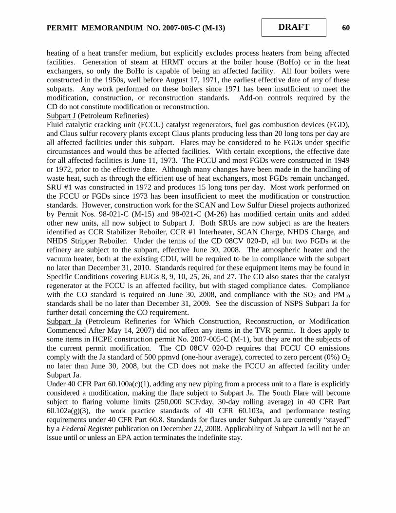
PERMIT MEMORANDUM NO. 2007-005-C (M-13) 60
DRAFT
heating of a heat transfer medium, but explicitly excludes process heaters from being affected
facilities. Generation of steam at HRMT occurs at the boiler house (BoHo) or in the heat
exchangers, so only the BoHo is capable of being an affected facility. All four boilers were
constructed in the 1950s, well before August 17, 1971, the earliest effective date of any of these
subparts. Any work performed on these boilers since 1971 has been insufficient to meet the
modification, construction, or reconstruction standards. Add-on controls required by the
CD do not constitute modification or reconstruction.
Subpart J (Petroleum Refineries)
Fluid catalytic cracking unit (FCCU) catalyst regenerators, fuel gas combustion devices (FGD),
and Claus sulfur recovery plants except Claus plants producing less than 20 long tons per day are
all affected facilities under this subpart. Flares may be considered to be FGDs under specific
circumstances and would thus be affected facilities. With certain exceptions, the effective date
for all affected facilities is June 11, 1973. The FCCU and most FGDs were constructed in 1949
or 1972, prior to the effective date. Although many changes have been made in the handling of
waste heat, such as through the efficient use of heat exchangers, most FGDs remain unchanged.
SRU #1 was constructed in 1972 and produces 15 long tons per day. Most work performed on
the FCCU or FGDs since 1973 has been insufficient to meet the modification or construction
standards. However, construction work for the SCAN and Low Sulfur Diesel projects authorized
by Permit Nos. 98-021-C (M-15) and 98-021-C (M-26) has modified certain units and added
other new units, all now subject to Subpart J. Both SRUs are now subject as are the heaters
identified as CCR Stabilizer Reboiler, CCR #1 Interheater, SCAN Charge, NHDS Charge, and
NHDS Stripper Reboiler. Under the terms of the CD 08CV 020-D, all but two FGDs at the
refinery are subject to the subpart, effective June 30, 2008. The atmospheric heater and the
vacuum heater, both at the existing CDU, will be required to be in compliance with the subpart
no later than December 31, 2010. Standards required for these equipment items may be found in
Specific Conditions covering EUGs 8, 9, 10, 25, 26, and 27. The CD also states that the catalyst
regenerator at the FCCU is an affected facility, but with staged compliance dates. Compliance
with the CO standard is required on June 30, 2008, and compliance with the SO2 and PM10
standards shall be no later than December 31, 2009. See the discussion of NSPS Subpart Ja for
further detail concerning the CO requirement.
Subpart Ja (Petroleum Refineries for Which Construction, Reconstruction, or Modification
Commenced After May 14, 2007) did not affect any items in the TVR permit. It does apply to
some items in HCPE construction permit No. 2007-005-C (M-1), but they are not the subjects of
the current permit modification. The CD 08CV 020-D requires that FCCU CO emissions
comply with the Ja standard of 500 ppmvd (one-hour average), corrected to zero percent (0%) O2
no later than June 30, 2008, but the CD does not make the FCCU an affected facility under
Subpart Ja.
Under 40 CFR Part 60.100a(c)(1), adding any new piping from a process unit to a flare is explicitly
considered a modification, making the flare subject to Subpart Ja. The South Flare will become
subject to flaring volume limits (250,000 SCF/day, 30-day rolling average) in 40 CFR Part
60.102a(g)(3), the work practice standards of 40 CFR 60.103a, and performance testing
requirements under 40 CFR Part 60.8. Standards for flares under Subpart Ja are currently “stayed”
by a Federal Register publication on December 22, 2008. Applicability of Subpart Ja will not be an
issue until or unless an EPA action terminates the indefinite stay.

PERMIT MEMORANDUM NO. 2007-005-C (M-13) 61
DRAFT
Subparts K, Ka, Kb (VOL Storage Vessels)
There are many tanks to consider. The earliest effective date of any of these subparts is June 11,
1973. All but ten of the hydrocarbon storage tanks were constructed before that date, have not
been modified to sufficient extent to meet the construction or modification criteria, and are not
affected sources.
Subpart K
Tank #13 in EUG 4 has capacity greater than 65,000 gallons, was constructed in 1976, and is an
affected source per 40 CFR 60.110(c)(1). Standards contained in §112 require a floating roof for
stored liquids with true vapor pressure (TVP) greater than 1.5 psia and a vapor recovery system
for liquids with TVP greater than 11.1 psia. Tank #13 is of internal floating roof construction
and does not contain liquids with TVP greater than 11.1 psia. Monitoring requirements are
described in §113 and include recording the liquid stored, the period of storage, and the
maximum TVP during the storage period.
Tank #63 in EUG 3 has capacity greater than 40,000 gallons, but less than 65,000 gallons.
Because the tank was constructed in 1973, it is not subject under either set of criteria described in
§ 60.110(c).
Subpart Ka
None of the tanks was constructed after May 18, 1978, and before July 23, 1984, within the
applicability window for Subpart Ka.
Subpart Kb
Tanks 9 and 16 in EUG 3, Tanks 4, 31, and 605 in EUG 5, and Tanks 474, 475, and 476 in EUG
20 were constructed after July 23, 1984. Tanks 9, 16, and 4 store liquids with vapor pressure
well below the thresholds set in §111b(b), and are not affected facilities. Tank 31 is a fixed roof
tank with carbon canisters on both the high- and low-pressure vents, satisfying the requirements of
§112b(a)(3). Tank 605 meets the standards of 40 CFR 60.112b(a) with an internal floating roof
(IFR) with a mechanical shoe seal, and satisfies the requirements of §112b(a)(1)(i – ix). Tanks
474, 475, and 476 meet these standards with external floating roofs (EFR) with primary and
secondary seals, and satisfy the requirements of §112b(a)(2)(i - iii).
Tanks 56 and 57 in EUG 4 are identified as subject to the standards of Kb in the discussion of
EUG 4, but this is only as a result of overlap provisions. Both 1,400-barrel fixed roof tanks were
constructed in 1992 and have never contained an organic liquid with vapor pressure sufficient to be
affected facilities.
Subpart GG (Stationary Gas Turbines)
There are no gas turbines at this facility.
Subpart UU (Asphalt Processing and Asphalt Roofing Manufacture)
Affected facilities at refineries are each asphalt storage tank and asphalt blowing still. HRMT
has no blowing stills. The effective date for tanks storing asphalt used for roofing only or for
roofing and other purposes is November 18, 1980. The effective date for tanks storing non-
roofing asphalt is May 26, 1981. The CDU, storage, and loading equipment that handles asphalt
were constructed in 1949. Any work performed on these tanks since 1981 has been insufficient
to meet the modification or construction criteria.

PERMIT MEMORANDUM NO. 2007-005-C (M-13) 62
DRAFT
Subparts VV and VVa (VOC Leaks in SOCMI)
Several subparts of NSPS make reference to Subpart VV, but these references do not make
equipment items or processes directly subject to Subparts VV or VVa. Propylene, a product
listed in these subparts, is manufactured by the refinery. Regardless of the preceding comments,
it has been determined that the refinery is currently subject only to Subpart GGG, which is
discussed below; two units will become subject to Subpart GGGa based on the modifications
proposed in this permit.
Subpart XX (Bulk Gasoline Terminals)
This subpart applies to loading racks at bulk gasoline terminals for which construction or
modification commenced after December 17, 1980. The four-spot rack was constructed in 1951,
and is not an affected facility. Any work performed on the rack since 1980 has been insufficient
to meet the modification or reconstruction criteria.
Subpart GGG (VOC Equipment Leaks in Petroleum Refineries)
A compressor is an affected facility and the group of all equipment within a process is an
affected facility. The word “equipment” in the preceding sentence is defined in 40 CFR 60.591
to mean each valve, pump, pressure relief device, sampling connection system, open-ended valve
or line, and flange or other connector in VOC service. Any affected facility that commences
construction or modification after January 4, 1983, and before November 7, 2006, is subject to
the requirements of this subpart. Much of the refinery was constructed or modified well before
1983, but numerous facilities listed in Section III: Equipment meet the applicability criteria used
here. They are identified in the Specific Conditions, as necessary.
Subpart GGGa (VOC Equipment Leaks in Petroleum Refineries)
This subpart affects each valve, pump, pressure relief device, sampling connection system, open-
ended valve or line, and flange or other connector in VOC service at a process unit, which
commenced construction or modification after November 7, 2006, and which is located at a
petroleum refinery. This subpart defines “process unit” as “components assembled to produce
intermediate or final products from petroleum, unfinished petroleum derivatives, or other
intermediates: a process unit can operate independently if supplied with sufficient feed or raw
materials and sufficient storage facilities for the product.” Subpart GGGa requires the leak
detection, repair, and documentation procedures of NSPS, Subpart VVa. All affected equipment
which commenced construction or modification after November 7, 2006, in VOC service is
subject to this subpart, including the modified CCR and DHTU and the BenZap Unit. All
applicable requirements have been incorporated into this permit.
Subpart KKK (VOC Equipment Leaks / Onshore Natural Gas Processing Plants)
No natural gas processing occurs at this facility.
Subpart LLL (Onshore Natural Gas Processing: SO2 Emissions)
No natural gas processing occurs at this facility.
Subpart QQQ (VOC from Petroleum Refinery Wastewater Systems)
Affected facilities include each individual drain system, each oil-water separator, and each
aggregate facility, where aggregate facility is the subject of further definition. Facilities
constructed, modified, or reconstructed after May 4, 1987, are subject to the requirements of this
subpart. Many of the facilities in the refinery were built before the effective date and are not
subject. Construction of the SCAN and Low Sulfur Diesel projects under Permit Nos. 98-021-C
(M-15) and 98-021-C (M-26) created several drain systems potentially subject to Subpart QQQ.
These systems include all drains at SCAN, NHDS, and SRU #2. New drains installed during
modification of the HTU to DHTU and modification of the CRU to CCR are also affected.

PERMIT MEMORANDUM NO. 2007-005-C (M-13) 63
DRAFT
Systems are grouped as Group 1 or Group 2 under Refinery MACT Subpart CC (q.v.), where
Group 1 members are those emission points to which control criteria apply. Under this division,
Group 1 activities are subject to the standards of MACT Subpart CC, while Group 2 activities
are subject to QQQ, if they meet the applicability criteria. An Applicability Determination
issued June 11, 2007, by George Czerniak of EPA, indicates that if a facility identifies a Group 2
system as Group 1, and subjects it to the control standards of NESHAP Subpart FF, that system
is exempt from NSPS QQQ. All of the mentioned systems are exempt from QQQ, except for
SRU #2, but they remain subject to MACT CC. Tanks subject to NSPS Subpart Kb are not
subject to the standards of Subpart QQQ, but they are subject to overlap provisions in MACT
Subpart CC. Specific Conditions address these overlaps.
Subpart JJJJ, Standards of Performance for Stationary Spark Ignition Internal Combustion
Engines (SI-ICE). This subpart was published in the Federal Register on January 18, 2008. It
promulgates emission standards for new SI engines ordered after June 12, 2006 and all SI
engines modified or reconstructed after June 12, 2006, regardless of size. All of the engines at
the facility are associated with the West Refinery, therefore, are addressed under a different
permit.
Subpart IIII, Standards of Performance for Stationary Compression Ignition Internal Combustion
Engines, affects stationary compression ignition (CI) internal combustion engines (ICE) based on
power and displacement ratings, depending on date of construction, beginning with those
constructed after July 11, 2005. For the purposes of this subpart, the date that construction
commences is the date the engine is ordered by the owner or operator. All of the engines at the
facility are associated with the West Refinery, therefore, are addressed under a different permit.
NESHAP, 40 CFR Part 61 [Subparts M and FF Applicable]
Of the pollutants listed in 40 CFR 61 (asbestos, benzene, beryllium, coke oven emissions,
inorganic arsenic, mercury, radionuclides, and vinyl chloride), only asbestos and benzene are
emitted by this facility. Several subparts cover emissions of benzene but all product streams are
less than the 10% threshold.
Subpart J (Equipment Leaks) The overhead from the reformate splitter will contain >10% benzene,
but the facility is only required to comply with the MACT CC Equipment Leak provisions as
described in the overlap provisions found in 40 CFR 63.640(p).
Subpart L (Coke By-Product Recovery) This facility is not an affected source.
Subpart M (Asbestos) applies to this facility. HRMT is involved in the removal of asbestos and
shall abide by the applicable requirements of §61.145.
Subpart Y (Benzene Storage Vessels) This facility is not an affected source.
Subpart BB (Benzene Transfer Operations) This facility is not an affected source.
Subpart FF (Benzene Waste Operations) This facility is a petroleum refinery and is an affected
source per 40 CFR 61.340(a). Sections (b) and (c) contain requirements implying coverage by
§§61.343 (Tanks), 61.344 (Surface impoundments), 61.345 (Containers), 61.346 (Individual
drain systems), 61.347 (Oil-water separators), 61.348 (Treatment processes), and 61.349
(Closed-vent systems and control devices). Sections 61.350-352 cover alternative methods.
Sections 61.354-6 concern monitoring, recording, and reporting benzene wastes, and contain a
great amount of detail on these topics.

PERMIT MEMORANDUM NO. 2007-005-C (M-13) 64
DRAFT
NESHAP, 40 CFR Part 63 [Subparts CC and UUU Applicable]
Subpart Q (Industrial Process Cooling Towers)
This subpart applies only to cooling towers using chrome. None is used by permittee.
Subpart R (Gasoline Distribution Facilities)
While the gasoline loading rack did not satisfy the 40 CFR 63.640(a) criteria for being an affected
facility under this subpart, it is an affected facility under Subpart CC, the standards for which are
found in Subpart R. See Subpart CC for further discussion.
Subpart CC (Petroleum Refineries)
Various process units and related emission points at petroleum refineries may be affected
sources. They must be located at a plant site that is a major source per §112(a) of the Clean Air
Act and they must emit or have equipment containing or contacting any of the organic HAP
listed in Table 1 of the subpart. Table 1 contains only 28 chemicals, including meta-, ortho-,
para-, and mixed isomers of both cresol and xylene. Organic HAP, as used in this subpart, refers
only to chemicals on this list of 28. HRMT is an affected facility. Following are the source
categories listed in 40 CFR 63.640(c) and a summary of applicable requirements for each.
(c)(1) Miscellaneous process vents from petroleum refining process units. Vents
identified as Group 1 vents are those having VOC emissions of at least 33 kilograms (73
pounds) per day from existing sources or at least 6.8 kilograms (15 pounds) per day from
new sources, both measured after any final recovery device, but before any control device
or discharge to the atmosphere. The VOC emissions must have organic HAP
concentrations of at least 20 ppmv. Either of two requirements described in §643 shall be
used for these emissions; a flare that meets the standards of 40 CFR 63.11(b), or a control
device that reduces the organic HAP content by 98% by weight, or to 20 ppmv dry,
corrected to 3% oxygen. If a boiler or process heater is used for the second option, the
vent stream shall be introduced into the flame zone. With one exception, all process
vents have been routed to one of the flares or to the refinery fuel gas (RFG) system. With
the new flare gas recovery system, all but those large events caused by malfunction will
be routed to RFG. Emissions routed to the RFG system are not affected sources, per
§640(d)(5). Emissions from the surface condensers in the vacuum tower at the CDU are
currently piped directly into the flame zone of the unit process heater, satisfying the
requirements of §643(b) and obviating the need for monitoring per §644(a)(3). This is
scheduled to change by December 31, 2010, under requirements of the CD.
(c)(2) Storage vessels associated with petroleum refining process units. Group 1 storage
vessels are required to comply with §§63.119 through 63.121 of Subpart G except as
provided for in §63.646(b) through (l). Group 1 storage vessels for an existing source are
those vessels with design capacity at least 177 m3 (46,758 gallons), storing a liquid with a
maximum true vapor pressure at least 10.4 kPa (1.5 psia) and annual average true vapor
pressure at least 8.3 kPa (1.2 psia), and storing a liquid with an annual average organic
HAP concentration greater than 4 percent by weight. Subpart G is the MACT for Process
Vents, Storage Vessels, Transfer Operations, and Wastewater at Synthetic Organic
Chemical Manufacturing Industries (SOCMI). Most of the exceptions are simply
substitute language to properly identify references and terminology; any substantive
exceptions will be identified in the Specific Conditions of this permit. The sections cited
essentially repeat the language of NSPS Subpart Kb. The compliance date for new tanks
is first operation, and the compliance date for all existing tanks was August 18, 2005.

PERMIT MEMORANDUM NO. 2007-005-C (M-13) 65
DRAFT
Because of overlap provisions to conform treatment of storage vessels with other NSPS or
NESHAP Subparts, each EUG containing storage vessels is addressed separately.
EUG 1 - Group 1 IFR tanks. All tanks, including those subject to NSPS Subpart K or Ka,
demonstrate compliance through MACT CC requirements.
EUG 2 - Group 1 EFR tanks. Same as EUG 1 requirements.
EUG 3 - Group 2 fixed roof tanks. Same as EUG 1 requirements, except that NSPS Subpart
K and Ka tanks are included only if they are not subject to control standards of those
subparts.
EUG 4 - Wastewater tanks. Overlap provisions with NSPS Subparts Kb and QQQ, NESHAP
Subpart FF, and MACT CC, including references to MACT G, require demonstration of
compliance with NSPS Subpart Kb to satisfy all requirements.
EUG 5 - IFR tanks subject to NSPS Subpart Kb. Compliance with Subpart Kb is sufficient.
EUG 7 - Group 2 EFR tank(s). Same as EUG 1 requirements, although this EUG contains no
NSPS tanks.
EUG 13 - MACT EEEEE tanks. None of these tanks is subject to MACT CC.
EUG 18 - MACT GGGGG tanks. None of these tanks is subject to MACT CC.
EUG 20 - EFR tanks subject to NSPS Subpart Kb. Compliance with Subpart Kb is
sufficient.
(c)(3) Wastewater streams and treatment operations associated with petroleum refining
process units. A Group 1 wastewater stream is one with a total benzene load of at least
10 megagrams (Mg) per year (11 TPY), a flow of at least 0.02 liters per minute (0.32
gph), a benzene concentration of at least 10 ppm, and not exempt from the control
requirements of NESHAP Subpart FF. HRMT‟s wastewater stream exceeds 10 Mg per
year and is subject to 40 CFR 61 FF. Individual streams may be exempted from control
requirements if they contain more than 10% water by volume, provided that the total
benzene content of such exempted streams does not exceed 6 Mg per year. Exemptions
of such streams must be demonstrated and documented.
(c)(4) Equipment leaks from petroleum refining process units. The standards for all
equipment are found in 40 CFR 60 Subpart VV, with certain minor exceptions. Among
these are the necessary corrections to definitions of organic HAP as found in MACT CC
and the requirement that all records be maintained for at least five years. Exceptions as
to new sources, hydrogen service, and others are described in the Specific Conditions.
(c)(5) Gasoline loading racks classified under SIC code 2911 shall comply with the
standards of 40 CFR 63 Subpart R, with the only exception relating to the definition of
organic HAP. Note that the ground flare used at the terminal is identical to a unit at
Sinclair‟s Casper (Wyoming) Refinery that was determined by EPA Region VIII to be
subject to monitoring as a thermal oxidation system, rather than as a flare. This device
requires a continuous parameter monitoring system (CPMS), according to 40 CFR
63.427. Temperature was monitored during the performance test of December 14, 2000,
but no correlation between temperature and TOC vapor destruction could be defined.
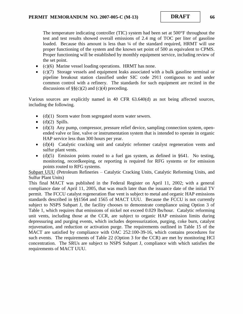
PERMIT MEMORANDUM NO. 2007-005-C (M-13) 66
DRAFT
The temperature indicating controller (TIC) system had been set at 500 F throughout the
test and test results showed overall emissions of 2.4 mg of TOC per liter of gasoline
loaded. Because this amount is less than ¼ of the standard required, HRMT will use
proper functioning of the system and the known set point of 500 as equivalent to CPMS.
Proper functioning will be established by monthly equipment service, including review of
the set point.
(c)(6) Marine vessel loading operations. HRMT has none.
(c)(7) Storage vessels and equipment leaks associated with a bulk gasoline terminal or
pipeline breakout station classified under SIC code 2911 contiguous to and under
common control with a refinery. The standards for such equipment are recited in the
discussions of §§(c)(2) and (c)(4) preceding.
Various sources are explicitly named in 40 CFR 63.640(d) as not being affected sources,
including the following.
(d)(1) Storm water from segregated storm water sewers.
(d)(2) Spills.
(d)(3) Any pump, compressor, pressure relief device, sampling connection system, open-
ended valve or line, valve or instrumentation system that is intended to operate in organic
HAP service less than 300 hours per year.
(d)(4) Catalytic cracking unit and catalytic reformer catalyst regeneration vents and
sulfur plant vents.
(d)(5) Emission points routed to a fuel gas system, as defined in §641. No testing,
monitoring, recordkeeping, or reporting is required for RFG systems or for emission
points routed to RFG systems.
Subpart UUU (Petroleum Refineries – Catalytic Cracking Units, Catalytic Reforming Units, and
Sulfur Plant Units)
This final MACT was published in the Federal Register on April 11, 2002; with a general
compliance date of April 11, 2005, that was much later than the issuance date of the initial TV
permit. The FCCU catalyst regeneration flue vent is subject to metal and organic HAP emissions
standards described in §§1564 and 1565 of MACT UUU. Because the FCCU is not currently
subject to NSPS Subpart J, the facility chooses to demonstrate compliance using Option 3 of
Table 1, which requires that emissions of nickel not exceed 0.029 lbs/hour. Catalytic reforming
unit vents, including those at the CCR, are subject to organic HAP emission limits during
depressuring and purging events, which includes depressurization, purging, coke burn, catalyst
rejuvenation, and reduction or activation purge. The requirements outlined in Table 15 of the
MACT are satisfied by compliance with OAC 252:100-39-16, which contains procedures for
such events. The requirements of Table 22 (Option 3 for the CCR) are met by monitoring HCl
concentration. The SRUs are subject to NSPS Subpart J, compliance with which satisfies the
requirements of MACT UUU.
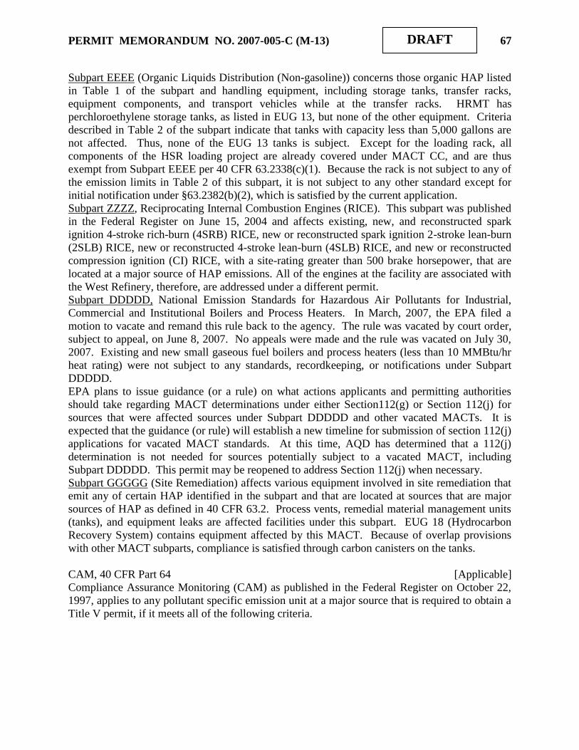
PERMIT MEMORANDUM NO. 2007-005-C (M-13) 67
DRAFT
Subpart EEEE (Organic Liquids Distribution (Non-gasoline)) concerns those organic HAP listed
in Table 1 of the subpart and handling equipment, including storage tanks, transfer racks,
equipment components, and transport vehicles while at the transfer racks. HRMT has
perchloroethylene storage tanks, as listed in EUG 13, but none of the other equipment. Criteria
described in Table 2 of the subpart indicate that tanks with capacity less than 5,000 gallons are
not affected. Thus, none of the EUG 13 tanks is subject. Except for the loading rack, all
components of the HSR loading project are already covered under MACT CC, and are thus
exempt from Subpart EEEE per 40 CFR 63.2338(c)(1). Because the rack is not subject to any of
the emission limits in Table 2 of this subpart, it is not subject to any other standard except for
initial notification under §63.2382(b)(2), which is satisfied by the current application.
Subpart ZZZZ, Reciprocating Internal Combustion Engines (RICE). This subpart was published
in the Federal Register on June 15, 2004 and affects existing, new, and reconstructed spark
ignition 4-stroke rich-burn (4SRB) RICE, new or reconstructed spark ignition 2-stroke lean-burn
(2SLB) RICE, new or reconstructed 4-stroke lean-burn (4SLB) RICE, and new or reconstructed
compression ignition (CI) RICE, with a site-rating greater than 500 brake horsepower, that are
located at a major source of HAP emissions. All of the engines at the facility are associated with
the West Refinery, therefore, are addressed under a different permit.
Subpart DDDDD, National Emission Standards for Hazardous Air Pollutants for Industrial,
Commercial and Institutional Boilers and Process Heaters. In March, 2007, the EPA filed a
motion to vacate and remand this rule back to the agency. The rule was vacated by court order,
subject to appeal, on June 8, 2007. No appeals were made and the rule was vacated on July 30,
2007. Existing and new small gaseous fuel boilers and process heaters (less than 10 MMBtu/hr
heat rating) were not subject to any standards, recordkeeping, or notifications under Subpart
DDDDD.
EPA plans to issue guidance (or a rule) on what actions applicants and permitting authorities
should take regarding MACT determinations under either Section112(g) or Section 112(j) for
sources that were affected sources under Subpart DDDDD and other vacated MACTs. It is
expected that the guidance (or rule) will establish a new timeline for submission of section 112(j)
applications for vacated MACT standards. At this time, AQD has determined that a 112(j)
determination is not needed for sources potentially subject to a vacated MACT, including
Subpart DDDDD. This permit may be reopened to address Section 112(j) when necessary.
Subpart GGGGG (Site Remediation) affects various equipment involved in site remediation that
emit any of certain HAP identified in the subpart and that are located at sources that are major
sources of HAP as defined in 40 CFR 63.2. Process vents, remedial material management units
(tanks), and equipment leaks are affected facilities under this subpart. EUG 18 (Hydrocarbon
Recovery System) contains equipment affected by this MACT. Because of overlap provisions
with other MACT subparts, compliance is satisfied through carbon canisters on the tanks.
CAM, 40 CFR Part 64 [Applicable]
Compliance Assurance Monitoring (CAM) as published in the Federal Register on October 22,
1997, applies to any pollutant specific emission unit at a major source that is required to obtain a
Title V permit, if it meets all of the following criteria.

PERMIT MEMORANDUM NO. 2007-005-C (M-13) 68
DRAFT
It is subject to an emission limit or standard for an applicable regulated air pollutant
It uses a control device to achieve compliance with the applicable emission limit or standard
It has potential emissions, prior to the control device, of the applicable regulated air
pollutant of 100 TPY
Although there have been very few emission limits for sources in the refinery, many sources
within the refinery are subject to the standards of 40 CFR 63 Subpart CC or Subpart UUU.
Provisions for monitoring contained in these subparts is considered presumptively acceptable
monitoring in accordance with 40 CFR 64.4(b)(4). The required explanation of the applicability
is found in the discussion for MACTs CC and UUU.
Chemical Accident Prevention Provisions, 40 CFR Part 68 [Applicable]
Naturally occurring hydrocarbon mixtures, prior to entry into a natural gas processing plant or a
petroleum refining process unit, including condensate, crude oil, field gas, and produced water,
are exempt for the purpose of determining whether more than a threshold quantity of a regulated
substance is present at the stationary source. Listed materials produced and held for sale as fuel
are also exempt. HRMT filed a Risk Management Plan with the EPA on June 21, 1999, and
filed a revised and updated plan on June 21, 2004. EPA‟s file number is 1000 0014 6567.
Stratospheric Ozone Protection, 40 CFR Part 82 [Subparts A and F are Applicable]
These standards require phase out of Class I & II substances, reductions of emissions of Class I
& II substances to the lowest achievable level in all use sectors, and banning use of nonessential
products containing ozone-depleting substances (Subparts A & C); control servicing of motor
vehicle air conditioners (Subpart B); require Federal agencies to adopt procurement regulations
which meet phase out requirements and which maximize the substitution of safe alternatives to
Class I and Class II substances (Subpart D); require warning labels on products made with or
containing Class I or II substances (Subpart E); maximize the use of recycling and recovery upon
disposal (Subpart F); require producers to identify substitutes for ozone-depleting compounds
under the Significant New Alternatives Program (Subpart G); and reduce the emissions of halons
(Subpart H).
Subpart A identifies ozone-depleting substances and divides them into two classes. Class I
controlled substances are divided into seven groups; the chemicals typically used by the
manufacturing industry include carbon tetrachloride (Class I, Group IV) and methyl chloroform
(Class I, Group V). A complete phase-out of production of Class I substances is required by
January 1, 2000 (January 1, 2002, for methyl chloroform). Class II chemicals, which are
hydrochlorofluorocarbons (HCFCs), are generally seen as interim substitutes for Class I CFCs.
Class II substances consist of 33 HCFCs. A complete phase-out of Class II substances,
scheduled in phases starting by 2002, is required by January 1, 2030.
Subpart F requires that any persons servicing, maintaining, or repairing appliances except for
motor vehicle air conditioners; persons disposing of appliances, including motor vehicle air
conditioners; refrigerant reclaimers, appliance owners, and manufacturers of appliances and
recycling and recovery equipment comply with the standards for recycling and emissions
reduction.

PERMIT MEMORANDUM NO. 2007-005-C (M-13) 69
DRAFT
The Standard Conditions of the permit address the requirements specified at §82.156 for persons
opening appliances for maintenance, service, repair, or disposal; §82.158 for equipment used
during the maintenance, service, repair, or disposal of appliances; §82.161 for certification by an
approved technician certification program of persons performing maintenance, service, repair, or
disposal of appliances; §82.166 for recordkeeping; § 82.158 for leak repair requirements; and
§82.166 for refrigerant purchase records for appliances normally containing 50 or more pounds
of refrigerant.
VIII. COMPLIANCE
Tier Classification and Public Review
This application has been classified as Tier II based on the request for a construction permit for a
significant modification to a Title V Operating permit. The applicant published the “Notice of
Filing Tier II Application” in The Tulsa World on June 30, 2010. A draft of this permit will also
be made available for public review for a period of 30 days as stated in another newspaper
announcement and will be available for review on the Air Quality section of the DEQ web page
at http://www.deq.state.ok.us.”
This facility is not located within 50 miles of the border with a contiguous state.
Fee Paid
Part 70 source construction permit application fee of $1,500.
IX. SUMMARY
This applicant has demonstrated the ability to comply with the requirements of the several air
pollution control rules and regulations. There are no compliance or enforcement issues
concerning this facility that would prevent the issuance of this permit. Issuance of the permit is
recommended, contingent on public and EPA review.

DRAFT
PERMIT TO CONSTRUCT
AIR POLLUTION CONTROL FACILITY
SPECIFIC CONDITIONS
Sinclair Tulsa Refining Company Permit Number 2007-005-C (M-13)
Tulsa Refinery
The permittee is authorized to construct in conformity with the specifications submitted to the Air
Quality Division (AQD) on May 7, 2010. The Evaluation Memorandum dated August 26, 2010,
explains the derivation of applicable permit requirements and estimates of emissions; however, it
does not contain operating limitations or permit requirements. Commencing construction or
continuing operations under this permit constitutes acceptance of, and consent to, the conditions
contained herein.
SPECIFIC CONDITION 1
Upon issuance of an operating permit following this operating permit, the permittee shall be
authorized to operate the affected facilities noted in this permit continuously (24 hours per day,
every day of the year) subject to the following conditions. Records necessary to show
compliance with each of the requirements below must be maintained. [OAC 252:100-8-6(a)(1)]
a. Combined emissions from Tanks 474 and 475 in EUG 20 are limited to 19.57 tons per year
(TPY) of volatile organic compounds (VOC). [98-021-TV]
b. Alkylate production is limited to 5,500 BPD based on a 12-month rolling average.
c. The following tanks have the throughput limits specified below.
Tank No. EUG Throughput Limit
4 5 45,600,000 barrels/year
9 3 19,000,000 barrels/year
16 3 19,000,000 barrels/year
31 5 430,080 barrels/year
476 20 16,261,905 barrels/year
d. The following fuel combustion units have heat input limits specified below. Compliance
with hourly heat inputs is shown by dividing the monthly heat input by the hours of
operation for the month.
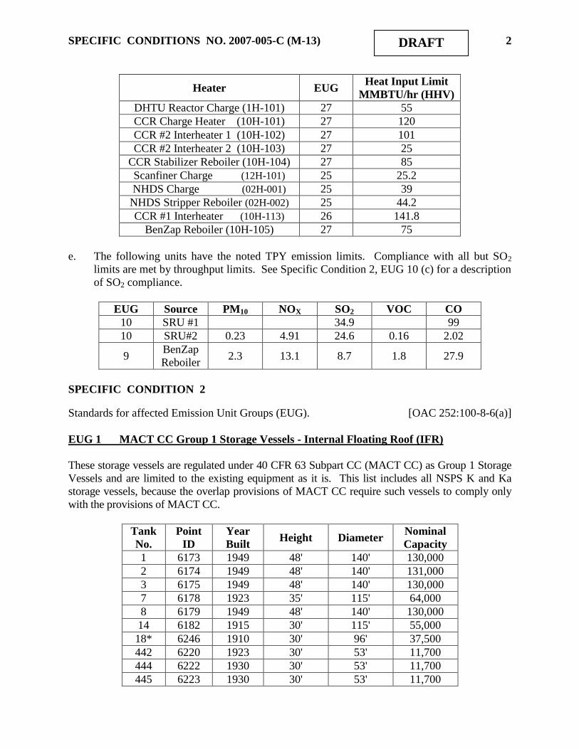
SPECIFIC CONDITIONS NO. 2007-005-C (M-13) 2 DRAFT
Heater EUG Heat Input Limit
MMBTU/hr (HHV)
DHTU Reactor Charge (1H-101) 27 55
CCR Charge Heater (10H-101) 27 120
CCR #2 Interheater 1 (10H-102) 27 101
CCR #2 Interheater 2 (10H-103) 27 25
CCR Stabilizer Reboiler (10H-104) 27 85
Scanfiner Charge (12H-101) 25 25.2
NHDS Charge (02H-001) 25 39
NHDS Stripper Reboiler (02H-002) 25 44.2
CCR #1 Interheater (10H-113) 26 141.8
BenZap Reboiler (10H-105) 27 75
e. The following units have the noted TPY emission limits. Compliance with all but SO2
limits are met by throughput limits. See Specific Condition 2, EUG 10 (c) for a description
of SO2 compliance.
EUG Source PM10 NOX SO2 VOC CO
10 SRU #1 34.9 99
10 SRU#2 0.23 4.91 24.6 0.16 2.02
9 BenZap
Reboiler 2.3 13.1 8.7 1.8 27.9
SPECIFIC CONDITION 2
Standards for affected Emission Unit Groups (EUG). [OAC 252:100-8-6(a)]
EUG 1 MACT CC Group 1 Storage Vessels - Internal Floating Roof (IFR)
These storage vessels are regulated under 40 CFR 63 Subpart CC (MACT CC) as Group 1 Storage
Vessels and are limited to the existing equipment as it is. This list includes all NSPS K and Ka
storage vessels, because the overlap provisions of MACT CC require such vessels to comply only
with the provisions of MACT CC.
Tank
No.
Point
ID
Year
Built Height Diameter
Nominal
Capacity
1 6173 1949 48' 140' 130,000
2 6174 1949 48' 140' 131,000
3 6175 1949 48' 140' 130,000
7 6178 1923 35' 115' 64,000
8 6179 1949 48' 140' 130,000
14 6182 1915 30' 115' 55,000
18* 6246 1910 30' 96' 37,500
442 6220 1923 30' 53' 11,700
444 6222 1930 30' 53' 11,700
445 6223 1930 30' 53' 11,700
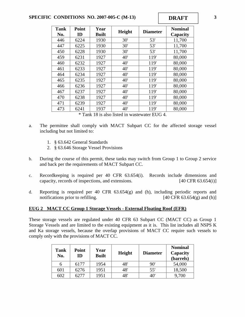
SPECIFIC CONDITIONS NO. 2007-005-C (M-13) 3 DRAFT
Tank
No.
Point
ID
Year
Built Height Diameter
Nominal
Capacity
446 6224 1930 30' 53' 11,700
447 6225 1930 30' 53' 11,700
450 6228 1930 30' 53' 11,700
459 6231 1927 40' 119' 80,000
460 6232 1927 40' 119' 80,000
461 6233 1927 40' 119' 80,000
464 6234 1927 40' 119' 80,000
465 6235 1927 40' 119' 80,000
466 6236 1927 40' 119' 80,000
467 6237 1927 40' 119' 80,000
470 6238 1927 40' 119' 80,000
471 6239 1927 40' 119' 80,000
473 6241 1937 40' 119' 80,000
* Tank 18 is also listed in wastewater EUG 4.
a. The permittee shall comply with MACT Subpart CC for the affected storage vessel
including but not limited to:
1. § 63.642 General Standards
2. § 63.646 Storage Vessel Provisions
b. During the course of this permit, these tanks may switch from Group 1 to Group 2 service
and back per the requirements of MACT Subpart CC.
c. Recordkeeping is required per 40 CFR 63.654(i). Records include dimensions and
capacity, records of inspections, and extensions. [40 CFR 63.654(i)]
d. Reporting is required per 40 CFR 63.654(g) and (h), including periodic reports and
notifications prior to refilling. [40 CFR 63.654(g) and (h)]
EUG 2 MACT CC Group 1 Storage Vessels - External Floating Roof (EFR)
These storage vessels are regulated under 40 CFR 63 Subpart CC (MACT CC) as Group 1
Storage Vessels and are limited to the existing equipment as it is. This list includes all NSPS K
and Ka storage vessels, because the overlap provisions of MACT CC require such vessels to
comply only with the provisions of MACT CC.
Tank
No.
Point
ID
Year
Built Height Diameter
Nominal
Capacity
(barrels)
6 6177 1954 48' 90' 54,000
601 6276 1951 48' 55' 18,500
602 6277 1951 48' 40' 9,700

SPECIFIC CONDITIONS NO. 2007-005-C (M-13) 4 DRAFT
a. The permittee shall comply with MACT CC for the affected storage vessel including but
not limited to:
1. § 63.642 General Standards
2. § 63.646 Storage Vessel Provisions
b. Per OAC 252:100-39-30(b)(4), these storage vessels are exempt from OAC 252:100-39-30.
c. Recordkeeping is required per 40 CFR 63.654(i). Records include dimensions and
capacity, records of inspections, and extensions. [40 CFR 63.654(i)]
d. Reporting is required per 40 CFR 63.654(g) and (h) including periodic reports, and
notifications prior to refilling. [40 CFR 63.654(g) and (h)]
EUG 3 MACT CC Group 2 Storage Vessels - Fixed Roof (FR)
These storage vessels are regulated under 40 CFR 63 Subpart CC (MACT CC) Group 2 Storage
Vessels and are limited to the existing equipment as it is. Due to the overlap provisions of MACT
CC §63.640(n), this list includes any Group 2 storage vessels that are also regulated under NSPS K
or Ka but are not required to meet any control standards, as they must meet these requirements per
§640(n)(7). Storage vessels required to meet control requirements under NSPS K and Ka are
required to comply only with those subparts (§640(n)(6)) and are not included in this list.
Tank
No. Point ID
Year
Built Height Diameter
Nominal
Capacity
9 1 6242 2005 48' 150' 151,100
10 6180 1910 30' 96' 37,500
11 6181 1910 30' 96' 37,500
15 6244 1949 48' 140' 130,000
16 6245 2003 48' 150' 151,100
17 6183 1910 30' 96' 37,500
34 6252 1922 30' 53' 11,700
36 6253 1922 30' 53' 11,500
40 6185 1923 40' 32' 6,100
41 6248 1922 35' 29' 3,900
63 41639 1973 18' 20' 1,000
102 6189 1907 30' 96' 37,500
103 6190 1907 30' 96' 37,500
104 6255 1907 30' 96' 37,500
107 6257 1949 48' 140' 131,000
108 6191 1907 30' 96' 37,500
109 6192 1907 30' 96' 37,500
110 6193 1907 30' 96' 37,500
111 6194 1907 30' 96' 37,500
112 6195 1907 30' 96' 37,500
115a 2 38828 2007 48' 150' 150,000

SPECIFIC CONDITIONS NO. 2007-005-C (M-13) 5 DRAFT
Tank
No. Point ID
Year
Built Height Diameter
Nominal
Capacity
115b 2 38842 2007 48' 150' 150,000
116 6199 1907 30' 96' 37,500
117 6200 1907 35' 115' 63,500
118 6201 1907 30' 96' 37,500
119 6202 1907 30' 96' 37,500
122 6203 1907 30' 96' 37,500
124 6261 1907 30' 96' 37,500
125 6262 1907 30' 96' 37,500
126 6263 1907 30' 96' 37,500
129 6204 1949 36' 35' 6,100
130 6205 1949 36' 35' 6,100
131 6265 1907 30' 96' 37,500
400 3 17035 1922 30' 24' 2,400
401 3 17036 1920 20' 25' 1,700
451 6229 1930 30' 53' 11,700
452 6230 1930 30' 53' 11,700
603 23132 1951 30' 20' 1,617
1 Replaces Tank 113 constructed 1907, per 98-021-TV (M-51).
2 Replaces Tank 115 constructed 1907, per 98-021-C (M-49).
3 Tank is also listed in wastewater EUG 4.
a. Fixed roof tanks in EUG 3 are subject to only the recordkeeping requirements of MACT
Subpart CC for Group 2 storage vessels, as follow. [40 CFR 63.654(i)(1)(iv)]
1. Readily accessible records showing the dimensions of each vessel and an analysis of
the capacity of each vessel shall be maintained for the life of the vessel.
[40 CFR 63.123(a)]
2. Data, assumptions, and procedures used in determining Group 2 status for these
tanks shall be documented. [40 CFR 63.646(b)(1)]
EUG 4 MACT CC Wastewater Tanks
These storage vessels are regulated under 40 CFR 63 Subpart CC (MACT CC) as wastewater
management units and are limited to the existing equipment as it is. Due to the overlap provisions
of MACT CC, the requirements of 40 CFR 61 Subpart FF (BWON), and 40 CFR 60 Subpart QQQ
(NSPS QQQ), these vessels are required to comply with 40 CFR 60 Subpart Kb to meet the
applicable standards under MACT CC, BWON, and NSPS QQQ.
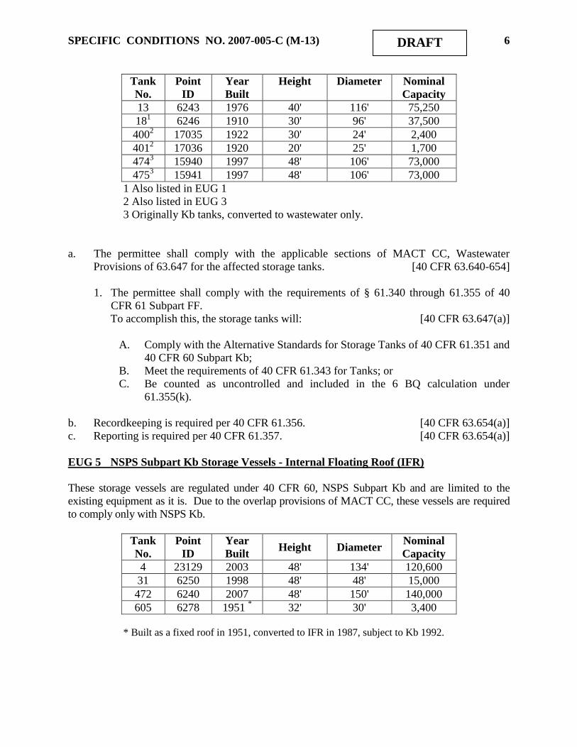
SPECIFIC CONDITIONS NO. 2007-005-C (M-13) 6 DRAFT
Tank
No.
Point
ID
Year
Built
Height Diameter Nominal
Capacity
13 6243 1976 40' 116' 75,250
181 6246 1910 30' 96' 37,500
4002 17035 1922 30' 24' 2,400
4012 17036 1920 20' 25' 1,700
4743 15940 1997 48' 106' 73,000
4753 15941 1997 48' 106' 73,000
1 Also listed in EUG 1
2 Also listed in EUG 3
3 Originally Kb tanks, converted to wastewater only.
a. The permittee shall comply with the applicable sections of MACT CC, Wastewater
Provisions of 63.647 for the affected storage tanks. [40 CFR 63.640-654]
1. The permittee shall comply with the requirements of § 61.340 through 61.355 of 40
CFR 61 Subpart FF.
To accomplish this, the storage tanks will: [40 CFR 63.647(a)]
A. Comply with the Alternative Standards for Storage Tanks of 40 CFR 61.351 and
40 CFR 60 Subpart Kb;
B. Meet the requirements of 40 CFR 61.343 for Tanks; or
C. Be counted as uncontrolled and included in the 6 BQ calculation under
61.355(k).
b. Recordkeeping is required per 40 CFR 61.356. [40 CFR 63.654(a)]
c. Reporting is required per 40 CFR 61.357. [40 CFR 63.654(a)]
EUG 5 NSPS Subpart Kb Storage Vessels - Internal Floating Roof (IFR)
These storage vessels are regulated under 40 CFR 60, NSPS Subpart Kb and are limited to the
existing equipment as it is. Due to the overlap provisions of MACT CC, these vessels are required
to comply only with NSPS Kb.
Tank
No.
Point
ID
Year
Built Height Diameter
Nominal
Capacity
4 23129 2003 48' 134' 120,600
31 6250 1998 48' 48' 15,000
472 6240 2007 48' 150' 140,000
605 6278 1951 * 32' 30' 3,400
* Built as a fixed roof in 1951, converted to IFR in 1987, subject to Kb 1992.

SPECIFIC CONDITIONS NO. 2007-005-C (M-13) 7 DRAFT
a. IFR Tanks in EUG 5 are subject to NSPS Kb. The “overlap” provisions of MACT CC
[§63.640(n)(1)] state that these storage vessels are required only to comply with the
provisions of Kb.
1. Mechanical design and operating specifications. [40 CFR 60.112b(a)(1)]
2. Compliance testing and procedures. [40 CFR 60.113b(a)]
3. Monitoring provisions [40 CFR 60.116b]
b. Tanks in this EUG may be used in MACT CC Group 1 wastewater service, as they comply
with the Alternative Standards for Storage Tanks of 40 CFR 61.351 and 40 CFR 60 Subpart
Kb.
c. Recordkeeping requirements include inspection results, dimensions and capacity of the
storage vessels, VOL stored, period of storage, and maximum TVP.
[40 CFR 60.115b and 116b]
d. Reporting requirements include semi-annual reporting of deviations during inspections,
notifications, and initial certifications. [40 CFR 60.116b]
EUG 6 Continuous Catalytic Reforming Unit (CCR)
The CCR is regulated by 40 CFR 63, Subpart UUU and is limited to inorganic HAP of 10 ppmvd
corrected to 3% oxygen at the regenerator stack. [40 CFR 63, Subpart UUU]
a. The CCR is subject to NESHAP, Subpart UUU and shall comply with all applicable
including but not limited to:
1. § 63.1560 What is the purpose of this subpart?
2. § 63.1561 Am I subject to this subpart?
3. § 63.1562 What parts of my plant are covered by this subpart?
4. § 63.1563 When do I have to comply with this subpart?
5. § 63.1566 What are my requirements for organic HAP emissions from catalytic
reforming units?
6. § 63.1567 What are my requirements for inorganic HAP emissions from catalytic
reforming units?
7. § 63.1569 What are my requirements for HAP emissions from bypass lines?
8. § 63.1570 What are my general requirements for complying with this subpart?
9. § 63.1572 What are my monitoring installation, operation, and maintenance
requirements?
10. § 63.1574 What notifications must I submit and when?
11. § 63.1577 What parts of the General Provisions apply to me?
b. Recordkeeping § 63.1576 What records must I keep, in what form, and for how long?
c. Reporting § 63.1575 What reports must I submit and when?

SPECIFIC CONDITIONS NO. 2007-005-C (M-13) 8 DRAFT
EUG 7 MACT CC Group 2 Storage Vessels External Floating Roof (EFR) Tank
This storage vessel is regulated under 40 CFR 63, Subpart CC (MACT CC) Group 2 Storage
Vessels and is limited to the existing equipment as it is.
Tank
No.
Point
ID
Year
Built
Height Diameter Nominal
Capacity
114 6197 1949 48' 140' 131,000
a. This tank is subject to only the recordkeeping requirements of MACT Subpart CC for Group
2 storage vessels, as follow. [40 CFR 63.654(i)(1)(iv)]
1.Readily accessible records showing the dimensions of each vessel and an analysis of the
capacity of each vessel shall be maintained for the life of the vessel.
[40 CFR 63.123(a)]
2.Data, assumptions, and procedures used in determining Group 2 status for each tank shall
be documented. [40 CFR 63.646(b)(1)]
EUG 8 Fired Boilers
The boilers are subject to NSPS Subpart J, effective June 30, 2008. These sources were
proposed for regulation under 40 CFR 63 Subpart DDDDD (MACT DDDDD), but that MACT
has been vacated. EPA plans to issue guidance or a rule on what actions applicants and
permitting authorities should take regarding MACT determinations under either Section 112(g)
or Section 112(j) for sources that were affected sources under Subpart DDDDD and other
vacated MACTs. It is expected that the guidance or rule will establish a new timeline for
submission of section 112(j) applications for vacated MACT standards. At this time, AQD has
determined that a 112(j) determination is not needed for sources potentially subject to a vacated
MACT, including Subpart DDDDD. This permit may be reopened to address Section 112(j)
when necessary. Each boiler is fitted with SCR for control of NOX and compliance is monitored
by CEMs.
ID Point ID Manufacturer Model/Burner type Construction Date
1 6150 Babcock & Wilcox FH 26 1950
2 6150 Babcock & Wilcox FH 26 1950
3 6151 Babcock & Wilcox FH 26 1950
4 6151 Babcock & Wilcox FH 26 1955
a. Nitrogen oxides emissions shall not exceed 0.20 lbs/MMBTU (3-hr average) or 0.03
lb/MMBTU (annual average). Compliance with this standard shall be demonstrated by use of a
continuous emissions monitoring system (CEMS) and the reporting/notification requirements of
40 CFR 60.7. The CEMS shall meet the requirements of 40 CFR 60.13. [CD]

SPECIFIC CONDITIONS NO. 2007-005-C (M-13) 9 DRAFT
b. All fuel-burning or refuse-burning equipment shall be operated to minimize emissions of
VOC. Among other things, such operation shall assure, based on manufacturer's data and good
engineering practice, that the equipment is not overloaded; that it is properly cleaned, operated,
and maintained; and that temperature and available air are sufficient to provide essentially
complete combustion. [OAC 252:100-37-36]
c. All boilers are subject to 40 CFR 60 Subpart J, and shall comply with all applicable
provisions including but not limited to: [40 CFR 60, Subpart J]
1. § 60.104 Standards for sulfur dioxide – (a)(1)
2. § 60.105 Monitoring of operations – (a)(4), (e)(3)(ii)
3. § 60.106 Test methods and procedures – (e)
[40 CFR 60, Subpart J; OAC 252:100-43]
d. Fuel oil shall not be burned except during periods of gas curtailment, operator training, or
test runs. [CD]
EUG 9 Fuel-Burning Equipment
Certain heaters have heat input limits, as identified in Specific Condition 1. According to the
June 30, 2008 CD, these fuel gas combustion devices (FGDs) are affected facilities under NSPS
Subpart J. A compliance date of June 30, 2008 applies to all FGDs, with the exception of the
atmospheric and vacuum heaters (ID 6155), which shall be in compliance no later than
December 31, 2010. These sources were proposed for regulation under 40 CFR 63 Subpart
DDDDD (MACT DDDDD), but that MACT has been vacated. EPA plans to issue guidance or a
rule on what actions applicants and permitting authorities should take regarding MACT
determinations under either Section 112(g) or Section 112(j) for sources that were affected
sources under Subpart DDDDD and other vacated MACTs. It is expected that the guidance or
rule will establish a new timeline for submission of section 112(j) applications for vacated
MACT standards. At this time, AQD has determined that a 112(j) determination is not needed
for sources potentially subject to a vacated MACT, including Subpart DDDDD. This permit
may be reopened to address Section 112(j) when necessary.
Source Point
ID
Manu-
facturer Burner Type
No. of
Burners
MMBTUH
(HHV)
Heater
Date
Atmospheric 6155 Foster-
Wheeler JZ-HEVD-12 26 200
2 1949
Vacuum 6155 Foster-
Wheeler JZ-HEVD-16 14 90
2 1949
FCCU Charge B-2 6158 M W
Kellogg JZ-VBM-14 32 150
2 1949
FCCU Air Heater
(B-1) 1
6159 M W
Kellogg Peabody M-18 1 38.4
2 1949
Unifiner Charge
H-1 6167
Refinery
Engr
JZ-UOV-4 Twin
head 12 42
2 1955
(1) vents to FCCU regenerator stack.
(2) estimated capacities per Sinclair; June 1998 DEQ facility inspection; not permit limits.
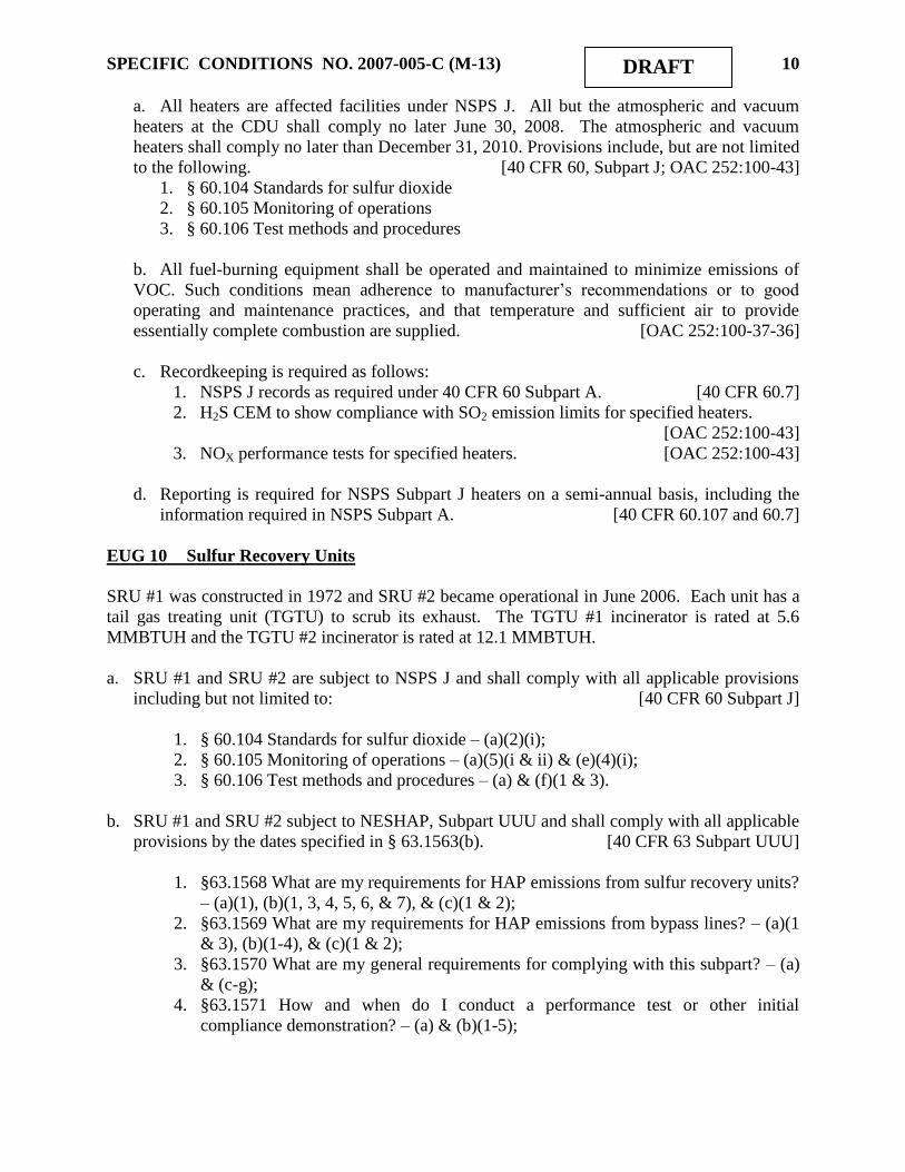
SPECIFIC CONDITIONS NO. 2007-005-C (M-13) 10 DRAFT
a. All heaters are affected facilities under NSPS J. All but the atmospheric and vacuum
heaters at the CDU shall comply no later June 30, 2008. The atmospheric and vacuum
heaters shall comply no later than December 31, 2010. Provisions include, but are not limited
to the following. [40 CFR 60, Subpart J; OAC 252:100-43]
1. § 60.104 Standards for sulfur dioxide
2. § 60.105 Monitoring of operations
3. § 60.106 Test methods and procedures
b. All fuel-burning equipment shall be operated and maintained to minimize emissions of
VOC. Such conditions mean adherence to manufacturer‟s recommendations or to good
operating and maintenance practices, and that temperature and sufficient air to provide
essentially complete combustion are supplied. [OAC 252:100-37-36]
c. Recordkeeping is required as follows:
1. NSPS J records as required under 40 CFR 60 Subpart A. [40 CFR 60.7]
2. H2S CEM to show compliance with SO2 emission limits for specified heaters.
[OAC 252:100-43]
3. NOX performance tests for specified heaters. [OAC 252:100-43]
d. Reporting is required for NSPS Subpart J heaters on a semi-annual basis, including the
information required in NSPS Subpart A. [40 CFR 60.107 and 60.7]
EUG 10 Sulfur Recovery Units
SRU #1 was constructed in 1972 and SRU #2 became operational in June 2006. Each unit has a
tail gas treating unit (TGTU) to scrub its exhaust. The TGTU #1 incinerator is rated at 5.6
MMBTUH and the TGTU #2 incinerator is rated at 12.1 MMBTUH.
a. SRU #1 and SRU #2 are subject to NSPS J and shall comply with all applicable provisions
including but not limited to: [40 CFR 60 Subpart J]
1. § 60.104 Standards for sulfur dioxide – (a)(2)(i);
2. § 60.105 Monitoring of operations – (a)(5)(i & ii) & (e)(4)(i);
3. § 60.106 Test methods and procedures – (a) & (f)(1 & 3).
b. SRU #1 and SRU #2 subject to NESHAP, Subpart UUU and shall comply with all applicable
provisions by the dates specified in § 63.1563(b). [40 CFR 63 Subpart UUU]
1. §63.1568 What are my requirements for HAP emissions from sulfur recovery units?
– (a)(1), (b)(1, 3, 4, 5, 6, & 7), & (c)(1 & 2);
2. §63.1569 What are my requirements for HAP emissions from bypass lines? – (a)(1
& 3), (b)(1-4), & (c)(1 & 2);
3. §63.1570 What are my general requirements for complying with this subpart? – (a)
& (c-g);
4. §63.1571 How and when do I conduct a performance test or other initial
compliance demonstration? – (a) & (b)(1-5);

SPECIFIC CONDITIONS NO. 2007-005-C (M-13) 11 DRAFT
5. §63.1572 What are my monitoring installation, operation, and maintenance
requirements? – (a)(1-4) & (d)(1-2);
6. §63.1574 What notifications must I submit and when? – (a)(2) & (f)(1, 2(i), 2(ii),
2(viii), 2(ix), & 2(x));
7. §63.1575 What reports must I submit and when? – (a-h);
8. §63.1576 What records must I keep, in what form, and for how long? – (a), (b)(1, 3,
4, 5), & (d-i);
9. §63.1577 What parts of the General Provisions apply to me?
c. SRU/TGTU #1 does not have continuous flow monitoring, but it does have CEMS for
monitoring concentrations of SO2 and O2. Maximum exhaust flow rates established by
performance testing shall be combined with SO2 CEMS readings to establish hourly and
annual SO2 emissions. Such testing, normally in conjunction with RATA testing of the
CEMS, shall be performed within 60 days after any construction project that increases
throughput to the SRU, but at intervals no greater than 12 months. [OAC 252:100-43]
d. Recordkeeping is required as follows.
1. Per NSPS Subparts A and J, including, but not limited to, CEMs information and
periods of excess emissions and monitor unavailable time.
[40 CFR 60.107 and 60.7]
2. Per MACT Subparts A and UUU, including, but not limited to, CEMs information,
periods of excess emissions, SSM records, performance and RATA tests, and OMM
records. [40 CFR 63.1576, 63.6, 63.8 and 63.10]
e. Reports are required as follow.
1. Per NSPS Subparts A and J, including, but not limited to, semi-annual compliance
reports and CEMs excess emission report. [40 CFR 60.107 and 60.7]
2. Per MACT Subparts A and UUU, including, but not limited to, semi-annual compliance
reports, SSM reports, and CEMs excess emission reports.
[40 CFR 63.1575, 63.6, 63.8, and 63.10]
EUG 11 FCCU
Emissions Limits:
Pollutant Emission Limit Averaging Period First Compliance Date
SO2 25 ppmdv @ 0% O2 365 days rolling December 31, 2010
50 ppmdv @ 0% O2 7 days rolling January 7, 2010
NOx 20 ppmdv @ 0% O2 365 days rolling December 31, 2010
40 ppmdv @ 0% O2 7 days rolling January 7, 2010
PM 1 lb PM / 1000 lbs
coke burn-off 3-hours June 30, 2008
CO 500 ppm 1-hour June 30, 2008
Opacity 30% 6-minutes June 30, 2008

SPECIFIC CONDITIONS NO. 2007-005-C (M-13) 12 DRAFT
a. The FCCU is subject to 40 CFR 63 Subpart UUU (MACT UUU) and shall comply with all
applicable requirements including but not limited to: [40 CFR 63 Subpart UUU]
1. §63.1560 What is the purpose of this subpart?
2. §63.1561 Am I subject to this subpart?
3. §63.1562 What parts of my plant are covered by this subpart?
4. §63.1563 When do I have to comply with this subpart?
5. §63.1564 What are my requirements for metal HAP emissions from catalytic cracking
units?
6. §63.1565 What are my requirements for organic HAP emissions from catalytic cracking
units?
7. §63.1570 What are my general requirements for complying with this subpart?
8. §63.1572 What are my monitoring installation, operation, and maintenance
requirements?
9. §63.1574 What notifications must I submit and when?
10. §63.1575 What reports must I submit and when?
11. §63.1576 What records must I keep, in what form, and for how long?
12. §63.1577 What parts of the General Provisions apply to me?
b. Per the June 30, 2008 CD, the FCCU is an affected facility under NSPS Subpart J for PM,
CO and SO2, and shall comply with all applicable requirements, including, but not
necessarily limited to the following.
1. §60.102 Standard for particulate matter. The CD requires compliance no later than
December 31, 2009.
2. §60.103 Standard for carbon monoxide. The CD required compliance no later than
June 30, 2008.
3. §60.104a Standards for sulfur oxides. The CD requires compliance no later than
December 31, 2009.
4. §60.105 Monitoring of emissions and operations.
5. §60.106 Test methods and procedures.
6. §60.107 Reporting and recordkeeping requirements.
7. §60.108 Performance test and compliance provisions.
c. A Selective Catalytic Reduction system shall be operated on the discharges from the FCCU
to meet the NOx emissions limits above.
d. NOx and SO2 emissions and O2 concentrations shall be monitored continuously using
continuous emission monitoring systems which are certified using the procedures of 40
CFR Part 60, Appendix B and F. Records of daily, 7-day rolling average, and 365-day
rolling averages shall be kept.
e. As an alternative to the monitoring requirements for opacity of NSPS Subpart J, a system
to monitor and record pressure differential across the wet scrubber, flue gas flow rate,
scrubber liquor flow rate, and flue gas to scrubber liquor injection rate may be installed an
operated. Any 3-hour period when the pressure differential is less than 70% of the average
pressure differential recorded during the latest performance testing, or any 3-hour period
when the scrubber liquor injection rate to flue gas flow rate is less than 70% of the average
value recorded during the latest performance testing shall be reported as excess emissions.

SPECIFIC CONDITIONS NO. 2007-005-C (M-13) 13 DRAFT
d. Recordkeeping
1. NSPS Subpart J, MACT Subparts A and UUU, including, but not limited to, CEMs and
COMS information, periods of excess emissions, SSM records, performance and
RATA tests, and OMM records. [40 CFR 60 Subpart J and 40 CFR 63 Subpart UUU]
e. Reporting per NSPS Subpart J, MACT Subparts A and UUU, including, but not limited to,
semi-annual compliance reports, SSM reports, and CEMs excess emission reports.
[40 CFR 60 Subpart J and 40 CFR 63 Subpart UUU]
EUG 12 Flares
There are no emission limits applied to this EUG under Title V but it is limited to the existing
equipment as it is. Sources in other EUGs under various regulations utilize the flares as air
pollution control devices. Monitoring, recordkeeping, and reporting requirements related to flare
pilot monitoring are found in each affected EUG, and not included here.
Flare Make/Model Height (ft) Date
#1 Zink/STF-SA-18 230 1949
#2 Zink/STF-SA-36-C 250 1972
a. The flares are regulated under 40 CFR 60 Subpart A and 40 CFR 63 Subpart A.
Requirements include, but are not limited to:
1. General control device requirements [40 CFR 60.18]
2. Control device requirements [40 CFR 63.11]
b. The flares shall be monitored continuously for the presence of a pilot flame. [40 CFR 60.18(f)]
c. The flares are subject to New Source Performance Standards (NSPS), Subpart J and shall
comply with all applicable provisions. [40 CFR Part 60, Subpart J]
1. § 60.104 Standards for SO2 – (a)(1);
2. § 60.105 Monitoring of operations – (a)(4), (e)(3)(ii);
3. § 60.106 Test methods and procedures – (e).
d. If the flare becomes subject to NSPS, Subpart Ja, the flare shall comply with all applicable
provisions of NSPS, Subpart Ja including but not limited to: [40 CFR Part 60, Subpart Ja]
1. § 60.102a Emissions limitations;
2. § 60.103a Work practice standards;
3. § 60.104a Performance tests;
4. § 60.107a Monitoring of emissions and operations for process heaters and other fuel
gas combustion devices; and
5. § 60.108a Recordkeeping and reporting requirements.
EUG 13 MACT EEEE Tanks
This EUG contains vessels subject to 40 CFR 63 Subpart EEEE. Because these perchloroethylene
tanks are smaller than 5,000 gallons, Subsection 63.2343(a) indicates that these emission sources do
not require control.
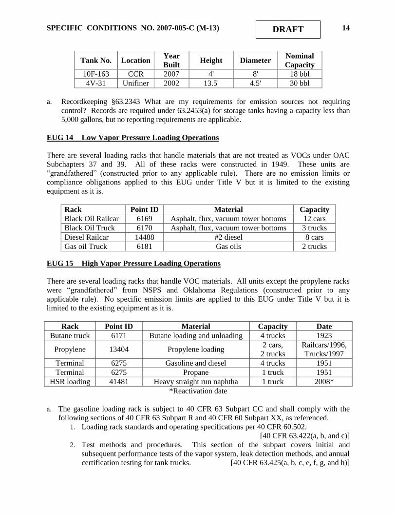
SPECIFIC CONDITIONS NO. 2007-005-C (M-13) 14 DRAFT
Tank No. Location Year
Built Height Diameter
Nominal
Capacity
10F-163 CCR 2007 4' 8' 18 bbl
4V-31 Unifiner 2002 13.5' 4.5' 30 bbl
a. Recordkeeping §63.2343 What are my requirements for emission sources not requiring
control? Records are required under 63.2453(a) for storage tanks having a capacity less than
5,000 gallons, but no reporting requirements are applicable.
EUG 14 Low Vapor Pressure Loading Operations
There are several loading racks that handle materials that are not treated as VOCs under OAC
Subchapters 37 and 39. All of these racks were constructed in 1949. These units are
“grandfathered” (constructed prior to any applicable rule). There are no emission limits or
compliance obligations applied to this EUG under Title V but it is limited to the existing
equipment as it is.
Rack Point ID Material Capacity
Black Oil Railcar 6169 Asphalt, flux, vacuum tower bottoms 12 cars
Black Oil Truck 6170 Asphalt, flux, vacuum tower bottoms 3 trucks
Diesel Railcar 14488 #2 diesel 8 cars
Gas oil Truck 6181 Gas oils 2 trucks
EUG 15 High Vapor Pressure Loading Operations
There are several loading racks that handle VOC materials. All units except the propylene racks
were “grandfathered” from NSPS and Oklahoma Regulations (constructed prior to any
applicable rule). No specific emission limits are applied to this EUG under Title V but it is
limited to the existing equipment as it is.
Rack Point ID Material Capacity Date
Butane truck 6171 Butane loading and unloading 4 trucks 1923
Propylene 13404 Propylene loading 2 cars,
2 trucks
Railcars/1996,
Trucks/1997
Terminal 6275 Gasoline and diesel 4 trucks 1951
Terminal 6275 Propane 1 truck 1951
HSR loading 41481 Heavy straight run naphtha 1 truck 2008*
*Reactivation date
a. The gasoline loading rack is subject to 40 CFR 63 Subpart CC and shall comply with the
following sections of 40 CFR 63 Subpart R and 40 CFR 60 Subpart XX, as referenced.
1. Loading rack standards and operating specifications per 40 CFR 60.502.
[40 CFR 63.422(a, b, and c)]
2. Test methods and procedures. This section of the subpart covers initial and
subsequent performance tests of the vapor system, leak detection methods, and annual
certification testing for tank trucks. [40 CFR 63.425(a, b, c, e, f, g, and h)]

SPECIFIC CONDITIONS NO. 2007-005-C (M-13) 15 DRAFT
b. A continuous parameter monitoring system (CPMS) capable of measuring temperature is in
the ductwork immediately downstream from the firebox in a position before any substantial
heat exchange occurs. The system shall not be operated below 500 F, the temperature
developed during performance testing. The system will shut down in the absence of a flame.
[40 CFR 63.427(a)(3) and (b), 40 CFR 60.503]
c. The gasoline loading rack is subject to certain state standards that are met through
compliance with MACT Subpart CC (item (a) above). [OAC 252:100-39-41(c)]
d. Recordkeeping requirements:
1. Records will be maintained per 40 CFR 63.428(b), (c), (g)(1), and (h)(1), (2), and (3),
as referenced in MACT CC. [40 CFR 63.654(b)]
2. Throughput and emission records shall be maintained for the propylene racks to
demonstrate their continued status as Insignificant Activity. [OAC 252:100-43]
e. Reporting Requirements will be maintained per 40 CFR 63.428(b), (c), (g)(1), and (h)(1), (2),
and (3), as referenced in MACT CC. [40 CFR 63.654(b)]
f. The HSR unloading rack is subject to only the initial notification requirements of MACT
EEEE. [40 CFR 63 Subpart EEEE]
EUG 16 Fugitive Emissions
Equipment leaks from the entire refinery, including but not limited to the process units, storage
tanks, and the terminal are included in this Group. There are no emission limits applied to this
EUG under Title V but it is limited to the existing equipment as it is. Because all equipment
leaks are subject to the LDAR requirements of OAC 252:100-39-15 and some are also subject to
LDAR requirements of NSPS Subparts GGG or GGGa, or to the LDAR requirements of MACT
CC, the permittee will comply by meeting the following conditions. Under the requirements of
the consent decree, all existing units accept NSPS Subpart GGG applicability. Units constructed
for the Heavy Crude Processing Expansion project under Permit No. 2007-005-C (M-1) and the
Distillate Hydrotreater Unit, Continuous Catalytic Reformer Unit, BenZap Unit, Coker
Blowdown, and Flare Gas Reduction Unit are subject to NSPS Subpart GGGa. (The NaSH Unit
will process inorganic materials, therefore, is not subject to NSPS Subpart GGGa.)
[40 CFR 60.590, 40 CFR 60.590a, and OAC 252:100-39-15]
a. All affected equipment, in HAP service (contacting > 5% by weight HAP), shall comply with
NESHAP, 40 CFR 63, Subpart CC. The permittee shall comply with the applicable sections
for each affected component. [40 CFR 63, Subpart CC]
1. § 63.642 General Standards – (c), (d)(1), (e), & (f);
2. § 63.648 Equipment Leak Standards – (a), (b), (c), & (e-i);
3. § 63.654 Reporting and Recordkeeping Requirements – (d), & (f-h).

SPECIFIC CONDITIONS NO. 2007-005-C (M-13) 16 DRAFT
b. Equipment constructed or modified after January 4, 1983, and on or before November 7,
2006, determined not to be in HAP service (contacting < 5% by weight HAP) and which is in
VOC service (contacting > 10% by weight VOC) shall comply with the requirements of
NSPS 40 CFR 60, Subpart GGG. [40 CFR 60, Subpart GGG]
1. §60.592 Standards (a-e).
2. §60.593 Exceptions (a-e).
3. These conditions reference the standards are described in §60.592 by reference to NSPS
Subpart VV §§60.482-1 through 60.482-10. Test methods and procedures, record-
keeping, and reporting are described in §§60.485, 486, and 487, respectively.
c. Equipment constructed or modified after November 7, 2006, determined not to be in HAP
service (contacting < 5% by weight HAP) and which is in VOC service (contacting > 10% by
weight VOC) shall comply with the requirements of NSPS 40 CFR 60, Subpart GGGa.
[40 CFR 60, Subpart GGGa]
1. §60.592a Standards (a-e).
2. §60.593a Exceptions (a-e).
3. These conditions reference the standards are described in §60.592a by reference to NSPS
Subpart VVa §§60.482-1a through 60.482-10a. Test methods and procedures, record-
keeping, and reporting are described in §§60.485a, 486a, and 487a, respectively.
d. Certain equipment is regulated as described in OAC 252:100-39-15.
e. Permittee shall maintain records identifying which components are regulated under each of
the requirements listed in a, b, and c preceding.
f. Recordkeeping provisions for these regulations are very extensive and are not summarized
here. Records for components covered by the above requirements are found in the applicable
rule. [40 CFR 63.654, 40 CFR 60.486, and OAC 252:100-39-15]
g. Reporting provisions for these regulations are very extensive and are not summarized here.
A single report may be submitted to comply with all of the reporting requirements above, so
long as all reporting requirements for each regulation are included.
[40 CFR 63.654, 40 CFR 60.487, and OAC 252:100-39-15]
EUG 17 Wastewater System
The wastewater system consists of several different sewer systems and the wastewater treatment
plant, as described in Part N of Section II (Facility Description) above. The facility is subject to
40 CFR 61 Subpart FF (BWON) and 40 CFR 63 Subpart CC (MACT CC), while areas of the
refinery are subject to 40 CFR 60 Subpart QQQ (NSPS QQQ). Due to the overlap regulations
under MACT CC (40 CFR 63.640(o)), all Group 1 wastewater streams also regulated under
NSPS QQQ must meet only MACT CC standards, while all Group 1 wastewater streams also
regulated under BWON must meet only BWON standards. A June 11, 2007, EPA Applicability
Determination (AD) issued to BP Products North America and signed by George Czerniak, states
that a Group 2 wastewater stream may be treated under BWON exclusively if the facility
declares it to be Group 1 and satisfies the requirements of Subpart FF for the stream. Given this
AD, the entire SCAN Unit, entire NHDS Unit, and new construction at the DHTU and CCR are
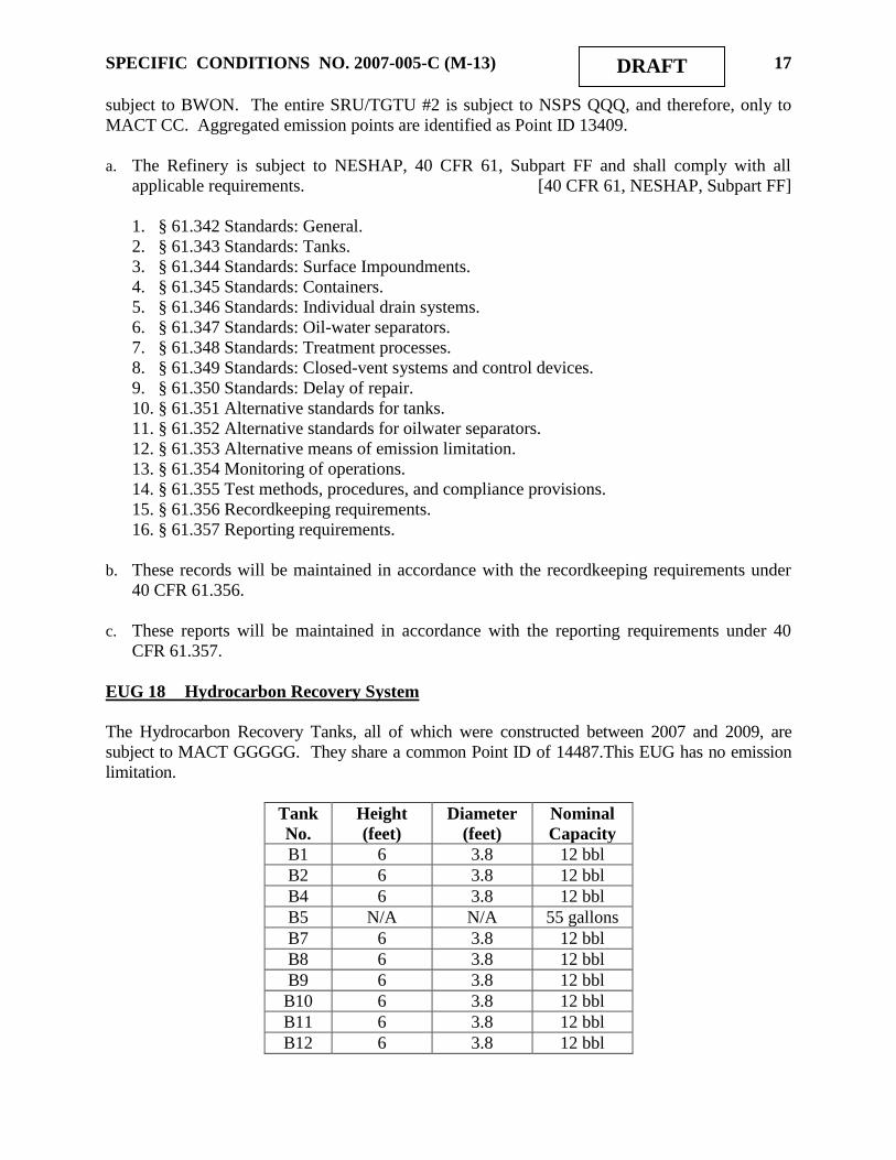
SPECIFIC CONDITIONS NO. 2007-005-C (M-13) 17 DRAFT
subject to BWON. The entire SRU/TGTU #2 is subject to NSPS QQQ, and therefore, only to
MACT CC. Aggregated emission points are identified as Point ID 13409.
a. The Refinery is subject to NESHAP, 40 CFR 61, Subpart FF and shall comply with all
applicable requirements. [40 CFR 61, NESHAP, Subpart FF]
1. § 61.342 Standards: General.
2. § 61.343 Standards: Tanks.
3. § 61.344 Standards: Surface Impoundments.
4. § 61.345 Standards: Containers.
5. § 61.346 Standards: Individual drain systems.
6. § 61.347 Standards: Oil-water separators.
7. § 61.348 Standards: Treatment processes.
8. § 61.349 Standards: Closed-vent systems and control devices.
9. § 61.350 Standards: Delay of repair.
10. § 61.351 Alternative standards for tanks.
11. § 61.352 Alternative standards for oilwater separators.
12. § 61.353 Alternative means of emission limitation.
13. § 61.354 Monitoring of operations.
14. § 61.355 Test methods, procedures, and compliance provisions.
15. § 61.356 Recordkeeping requirements.
16. § 61.357 Reporting requirements.
b. These records will be maintained in accordance with the recordkeeping requirements under
40 CFR 61.356.
c. These reports will be maintained in accordance with the reporting requirements under 40
CFR 61.357.
EUG 18 Hydrocarbon Recovery System
The Hydrocarbon Recovery Tanks, all of which were constructed between 2007 and 2009, are
subject to MACT GGGGG. They share a common Point ID of 14487.This EUG has no emission
limitation.
Tank
No.
Height
(feet)
Diameter
(feet)
Nominal
Capacity
B1 6 3.8 12 bbl
B2 6 3.8 12 bbl
B4 6 3.8 12 bbl
B5 N/A N/A 55 gallons
B7 6 3.8 12 bbl
B8 6 3.8 12 bbl
B9 6 3.8 12 bbl
B10 6 3.8 12 bbl
B11 6 3.8 12 bbl
B12 6 3.8 12 bbl

SPECIFIC CONDITIONS NO. 2007-005-C (M-13) 18 DRAFT
a. Site remediation activities at the refinery are subject to 40 CFR 63 Subpart GGGGG and the
refinery shall comply with any applicable requirements including but not limited to:
[40 CFR 63 Subpart GGGGG]
1. §63.7880 - 7883 What This Subpart Covers
2. §63.7884 - 7888 General Standards
3. §63.7890 - 7893 Process Vents
4. §63.7895 - 7898 Tanks
5. §63.7900 - 7903 Containers
6. §63.7920 - 7922 Equipment Leaks
7. §63.7935 - 7938 General Compliance Requirements
8. §63.7950 - 7953 Notifications, Reports, and Recordkeeping
9. §63.7955 - 7957 Other Requirements and Information
10. The permittee shall comply with the provisions of 40 CFR 63 Subpart A as specified in
Appendix to Subpart GGGGG, Table 3.
EUG 19 Cooling Towers
Cooling towers are considered to be trivial sources for Title V purposes, so the following table is
shown only for completeness.
Number Point ID Purpose Date
3 25053 Cooling water for the FCCU 1949
3a 25054 Cooling water for SCANfiner 2003
4 and 5 25055 Cooling water for the CDU 1949
7 25056 Cooling water for the ALKY, POLY & ISOM 2007*
8 25057 Cooling water for the OIF 1972
* Replaced tower built in 1949.
EUG 20 NSPS Kb Tanks (EFR) - MACT CC Group 1 Wastewater
This storage vessel is regulated under 40 CFR 60, Subpart Kb and is limited to the existing
equipment as it is. Due to the overlap provisions of MACT CC, this vessel is required to comply
only with Kb, except as noted in 40 CFR 63.640(n)(8).
Tank
No.
Point
ID
Year
Built Height Diameter
Nominal
Capacity
476 36590 2005 45' 55‟ 15,000
a. EFR Tanks in EUG 20 are subject to NSPS Subpart Kb. The “overlap” provisions of
MACT CC [§63.640(n)(1)] state that these storage vessels are required only to comply with
the provisions of Kb, with the modifications noted in 63.640(n)(8).
1. Mechanical design and operating specifications. [40 CFR 60.112b(a)(2)]
2. Compliance testing and procedures. [40 CFR 60.113b(b)]
3. Monitoring provisions [40 CFR 60.116b]
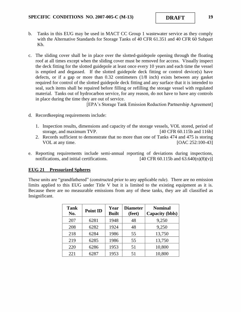
SPECIFIC CONDITIONS NO. 2007-005-C (M-13) 19 DRAFT
b. Tanks in this EUG may be used in MACT CC Group 1 wastewater service as they comply
with the Alternative Standards for Storage Tanks of 40 CFR 61.351 and 40 CFR 60 Subpart
Kb.
c. The sliding cover shall be in place over the slotted-guidepole opening through the floating
roof at all times except when the sliding cover must be removed for access. Visually inspect
the deck fitting for the slotted guidepole at least once every 10 years and each time the vessel
is emptied and degassed. If the slotted guidepole deck fitting or control device(s) have
defects, or if a gap or more than 0.32 centimeters (1/8 inch) exists between any gasket
required for control of the slotted guidepole deck fitting and any surface that it is intended to
seal, such items shall be repaired before filling or refilling the storage vessel with regulated
material. Tanks out of hydrocarbon service, for any reason, do not have to have any controls
in place during the time they are out of service.
[EPA‟s Storage Tank Emission Reduction Partnership Agreement]
d. Recordkeeping requirements include:
1. Inspection results, dimensions and capacity of the storage vessels, VOL stored, period of
storage, and maximum TVP. [40 CFR 60.115b and 116b]
2. Records sufficient to demonstrate that no more than one of Tanks 474 and 475 is storing
VOL at any time. [OAC 252:100-43]
e. Reporting requirements include semi-annual reporting of deviations during inspections,
notifications, and initial certifications. [40 CFR 60.115b and 63.640(n)(8)(v)]
EUG 21 Pressurized Spheres
These units are “grandfathered” (constructed prior to any applicable rule). There are no emission
limits applied to this EUG under Title V but it is limited to the existing equipment as it is.
Because there are no measurable emissions from any of these tanks, they are all classified as
Insignificant.
Tank
No.
Point ID
Year
Built
Diameter
(feet)
Nominal
Capacity (bbls)
207
6281
1948
48
9,250
208
6282
1924
48
9,250
218
6284
1986
55
13,750
219
6285
1986
55
13,750
220
6286
1953
51
10,800
221
6287
1953
51
10,800
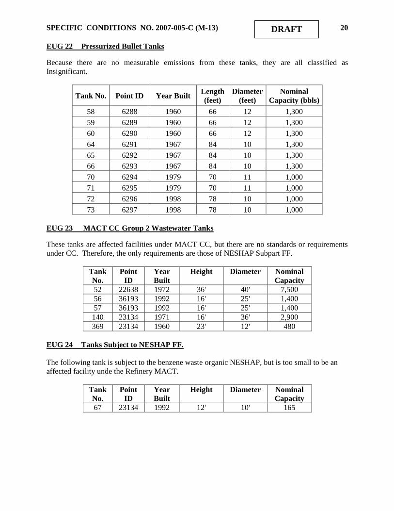
SPECIFIC CONDITIONS NO. 2007-005-C (M-13) 20 DRAFT
EUG 22 Pressurized Bullet Tanks
Because there are no measurable emissions from these tanks, they are all classified as
Insignificant.
Tank No.
Point ID
Year Built
Length
(feet)
Diameter
(feet)
Nominal
Capacity (bbls)
58
6288
1960
66
12
1,300
59
6289
1960
66
12
1,300
60
6290
1960
66
12
1,300
64
6291
1967
84
10
1,300
65
6292
1967
84
10
1,300
66
6293
1967
84
10
1,300
70
6294
1979
70
11
1,000
71
6295
1979
70
11
1,000
72
6296
1998
78
10
1,000
73
6297
1998
78
10
1,000
EUG 23 MACT CC Group 2 Wastewater Tanks
These tanks are affected facilities under MACT CC, but there are no standards or requirements
under CC. Therefore, the only requirements are those of NESHAP Subpart FF.
Tank
No.
Point
ID
Year
Built
Height Diameter Nominal
Capacity
52 22638 1972 36' 40' 7,500
56 36193 1992 16' 25' 1,400
57 36193 1992 16' 25' 1,400
140 23134 1971 16' 36' 2,900
369 23134 1960 23' 12' 480
EUG 24 Tanks Subject to NESHAP FF.
The following tank is subject to the benzene waste organic NESHAP, but is too small to be an
affected facility unde the Refinery MACT.
Tank
No.
Point
ID
Year
Built
Height Diameter Nominal
Capacity
67 23134 1992 12' 10' 165

SPECIFIC CONDITIONS NO. 2007-005-C (M-13) 21 DRAFT
EUG 25 New Fuel-Burning Equipment with Heat Input < 100MMBTUH
This EUG contains new fuel-burning equipment with heat input less than 100 MMBTUH. These
sources were proposed for regulation under 40 CFR 63 Subpart DDDDD (MACT DDDDD), but
that MACT has been vacated. EPA plans to issue guidance or a rule on what actions applicants
and permitting authorities should take regarding MACT determinations under either Section
112(g) or Section 112(j) for sources that were affected sources under Subpart DDDDD and other
vacated MACTs. It is expected that the guidance or rule will establish a new timeline for
submission of section 112(j) applications for vacated MACT standards. At this time, AQD has
determined that a 112(j) determination is not needed for sources potentially subject to a vacated
MACT, including Subpart DDDDD. This permit may be reopened to address Section 112(j)
when necessary.
Source Point
ID Manufacturer
Burner
Type
No. of
Burners
MMBTUH
(HHV)
Const.
Date
NOx
lb/MMBTU
(HHV)
Scanfiner Charge
(12H-101) 23133
Tulsa
Heaters, Inc
ZeeCo
New Gen
Low NOX
3 25.2 2004 0.07
NHDS Charge
(02H-001) 36580
Tulsa
Heaters, Inc
ZeeCo
Low NOx 4 39 2006 0.05
NHDS Stripper
Reboiler
(02H-002)
36584 Tulsa
Heaters, Inc
ZeeCo
Next Gen
Low NOx
6 44.2 2006 0.05
a. Compliance with the SO2 limits is demonstrated by compliance with the 0.1 gr/dscf H2S limit
imposed on fuel gas combustion devices by NSPS Subpart J and fuel input. Compliance with
the fuel input limits will be calculated by using the monthly fuel input to calculate hourly
average heat input. [40 CFR 60, Subpart J and OAC 252:100-43]
b. Compliance with the NOX limits is demonstrated by performance testing of the low-NOX
burners. Compliance with these limits is demonstrated by heat input to each unit, using
monthly fuel inputs to calculate hourly averages. [OAC 252:100-43]
c. All heaters must comply with 40 CFR 60 Subpart J, and shall comply with all applicable
provisions including but not limited to: [40 CFR 60, Subpart J and OAC 252:100-43]
1. § 60.104 Standards for sulfur dioxide – (a)(1)
2. § 60.105 Monitoring of operations – (a)(4), (e)(3)(ii)
3. § 60.106 Test methods and procedures – (e)
d. Compliance with the H2S destruction efficiency criterion and H2S emission limitation of
OAC 252:100-31-25 concerning the SCANfiner process unit shall be demonstrated using the
SRU CEMS or through engineering calculations and judgment. [OAC 252:100-31]

SPECIFIC CONDITIONS NO. 2007-005-C (M-13) 22 DRAFT
e. Recordkeeping is required as follows:
1. NSPS J records as required under 40 CFR 60 Subpart A. [40 CFR 60.7]
2. H2S CEM to show compliance with SO2 emission limits for specified heaters.
[OAC 252:100-43]
3. NOx performance tests for specified heaters. [OAC 252:100-43]
4. Monthly fuel use for each piece of fuel-burning equipment in EUG 25 with a heat input
limit shall be maintained, along with a calculation demonstrating that the average hourly
firing rate of each item is not greater than the heat rate set forth in SC #1. These records
shall be maintained on a 12-month rolling basis. [OAC 252:100-43]
f. Reporting is required for NSPS Subpart J heaters on a semi-annual basis, including the
information required in NSPS Subpart A. [40 CFR 60.107 and 60.7]
EUG 26 New Fuel-Burning Equipment with Heat Input ≥ 100MMBTUH
These sources are all regulated under NSPS J. These sources were proposed for regulation under
40 CFR 63 Subpart DDDDD (MACT DDDDD), but that MACT has been vacated. EPA plans to
issue guidance or a rule on what actions applicants and permitting authorities should take
regarding MACT determinations under either Section 112(g) or Section 112(j) for sources that
were affected sources under Subpart DDDDD and other vacated MACTs. It is expected that the
guidance or rule will establish a new timeline for submission of section 112(j) applications for
vacated MACT standards. At this time, AQD has determined that a 112(j) determination is not
needed for sources potentially subject to a vacated MACT, including Subpart DDDDD. This
permit may be reopened to address Section 112(j) when necessary.
Source Point
ID Manufacturer
Burner
Type
No. of
Burners
MMBTUH
(HHV) Const. Date
NOx
lb/MMBTU
(HHV)
CCR #1
Interheater
(10H-113)
3922
5
Tulsa Heaters,
Inc
ZeeCo,
Inc. 18 141.8 2005 0.05
a. Compliance with the SO2 limit is demonstrated by compliance with the 0.1 gr/dscf H2S limit
imposed on fuel gas combustion devices by NSPS Subpart J and fuel input. Compliance with
the fuel input limits will be calculated by using the monthly fuel input to calculate hourly
average heat input. [40 CFR 60, Subpart J and OAC 252:100-43]
b. Compliance with the NOX limit is demonstrated by performance testing of the low-NOX
burners. Compliance with these limits is demonstrated by heat input to each unit, using
monthly fuel inputs to calculate hourly averages. [OAC 252:100-43]
c. All heaters must comply with 40 CFR 60 Subpart J, and shall comply with all applicable
provisions including but not limited to: [40 CFR 60, Subpart J and OAC 252:100-43]
1. § 60.104 Standards for sulfur dioxide – (a)(1)
2. § 60.105 Monitoring of operations – (a)(4), (e)(3)(ii)
3. § 60.106 Test methods and procedures – (e)

SPECIFIC CONDITIONS NO. 2007-005-C (M-13) 23 DRAFT
d. Recordkeeping is required as follows:
1. NSPS J records as required under 40 CFR 60 Subpart A. [40 CFR 60.7]
2. H2S CEM to show compliance with SO2 emission limits for specified heaters.
[OAC 252:100-43-4]
3. NOX performance tests for specified heaters. [OAC 252:100-43-3]
4. Monthly fuel use for each piece of fuel-burning equipment with a heat input limit shall be
maintained, along with a calculation demonstrating that the average hourly firing rate of
each item is not greater than the heat rate set forth in SC #1. These records shall be
maintained on a 12-month rolling basis. [OAC 252:100-43-7]
e. Reporting is required for NSPS Subpart J heaters on a semi-annual basis, including the
information required in NSPS Subpart A. [40 CFR 60.107 and 60.7]
EUG 27 Existing Fuel-Burning Equipment Accepting NOX Limits
The following table shows available information for certain heaters. These sources were
proposed for regulation under 40 CFR 63 Subpart DDDDD (MACT DDDDD), but that MACT
has been vacated. EPA plans to issue guidance or a rule on what actions applicants and
permitting authorities should take regarding MACT determinations under either Section 112(g)
or Section 112(j) for sources that were affected sources under Subpart DDDDD and other
vacated MACTs. It is expected that the guidance or rule will establish a new timeline for
submission of section 112(j) applications for vacated MACT standards. At this time, AQD has
determined that a 112(j) determination is not needed for sources potentially subject to a vacated
MACT, including Subpart DDDDD. This permit may be reopened to address Section 112(j)
when necessary.
Source Point
ID
Manu-
facturer Burner Type
No. of
Burners
MMBTUH
(HHV)
Heater
Date
NOx
lb/MMBTU
(HHV)
DHTU Reactor
Charge 1H-101 6156
Foster-
Wheeler JZ-LOF-27-30 16 55 1972
1 0.20
CCR Charge Heater
10H-101 1
6163 SELAS JZ MA-20 12 120 19722 0.05
CCR Inter-heater
#2-1 10H-102 6163 SELAS
Callidus CRG-
LN-8P 8 101 1972 0.20
CCR Interheater
#2-2 10H-103 6163 SELAS JZ MA-22 2 25 1972 0.20
CCR Stabilizer
Reboiler 10H-104 6162 SELAS JZ MA-20 8 85 1972
2 0.05
BenZap Heater 6162 -- -- -- 75 19721 0.04
1 low-NOx burners to be installed in 2011.
2 low-NOX burners installed in 2005.

SPECIFIC CONDITIONS NO. 2007-005-C (M-13) 24 DRAFT
a. Compliance with the NOX limits is demonstrated by performance testing of the low-NOX
burners. Compliance with these limits is demonstrated by heat input to each unit, using
monthly fuel inputs to calculate hourly averages.
b. Monthly fuel use for each piece of fuel-burning equipment with a heat input limit shall be
maintained, along with a calculation demonstrating that the average hourly firing rate of each
item is not greater than the heat rate set forth in SC #1. These records shall be maintained on
a 12-month rolling basis. [OAC 252:100-43-7]
c. Testing of NOx emissions (lb/MMBTU) shall be conducted using EPA Methods 7E and 3 or
3A at least once a year for the next five years on each of the above heaters. Emissions of
NOx as reported in annual Emissions Inventories and records as required for “EUG
Plantwide” shall be no lower than testing results. [OAC 252:100-43]
d. Per the CD 08CV 020-D, these heaters are affected facilities under NSPS Subpart J and shall
comply with all applicable requirements, including, but not necessarily limited to the
following.
1. §60.104 Standards for sulfur oxides. The CD requires compliance no later than
December 31, 2010.
2. §60.105 Monitoring of emissions and operations.
3. §60.106 Test methods and procedures.
4. §60.107 Reporting and recordkeeping requirements.
5. §60.108 Performance test and compliance provisions.
Insignificant Activities
Various records shall be maintained to demonstrate the continued status of certain emission
sources as Insignificant Activities, as follow. [OAC 252:100-43]
1. The amount of fuel dispensed from tanks #419 and #420 (monthly).
2. Vapor pressure for any tanks satisfying the criteria of capacity less than 39,894 gallons and
storing a liquid with vapor pressure less than 1.5 psia (annual maximum).
3. Number of drums no larger than 55 gallons and containing less than 3% by volume of
residual material, washed and/or crushed (annual).
4. Total emissions from any source classified as Insignificant on the basis of its emissions
(annual), as well as a description of the calculation method used and data used in the
calculation.
EUG Plantwide Miscellaneous
a. Certain equipment within the refinery is subject to 40 CFR 63 Subpart CC and all affected
equipment shall comply with all applicable requirements. Requirements listed in previous
EUGs are not repeated here. [40 CFR 63 Subpart CC]

SPECIFIC CONDITIONS NO. 2007-005-C (M-13) 25 DRAFT
1. § 63. 63.642 General Standards
2. § 63.643 Miscellaneous Process Vent Provisions
3. § 63.644 Monitoring for Miscellaneous Process Vents
4. § 63.645 Test Methods and Procedures for Miscellaneous Process Vents
5. § 63.654 Reporting and Recordkeeping Requirements
6. The permittee shall comply with the provisions of 40 CFR 63 Subpart A as specified in
Appendix to Subpart CC, Table 6.
b. Various asbestos renovation and demolition projects at the Tulsa Refinery are subject to State
and Federal standards, including:
1. The federal standards found in 40 CFR 61 Subpart M. [40 CFR 61.145]
2. The following requirements for handling asbestos are in addition to those listed in the
asbestos NESHAP, 40 CFR 61 Subpart M. [OAC 252:100-40-5]
A. Before being handled, stored or transported in or to the outside air, friable asbestos
from demolition/renovation operations shall be double bagged in six-mil plastic bags,
or single bagged in one six-mil plastic bag and placed in a disposable drum, or
contained in any other manner approved in advance by the AQD Director.
B. When demolition/renovation operations must take place in the outdoor air, friable
asbestos removed in such operations shall be immediately bagged or contained in
accordance with (A).
C. Friable asbestos materials used on pipes or other outdoor structures shall not be allowed
to weather or deteriorate and become exposed to, or dispersed in the outside air.
D. Friable asbestos materials shall, in addition to other provisions concerning disposal, be
disposed of in a facility approved for asbestos by the Solid Waste Management
Division of DEQ.
c. The following procedures are required for any process unit shutdown, purging, or blowdown
operation. [OAC 252:100-39-16]
1. Recovery of VOC shall be accomplished during the shutdown or turnaround to a process
unit pressure compatible with the flare or vapor system pressure. The unit shall then be
purged or flushed to a flare or vapor recovery system using a suitable material such as
steam, water or nitrogen. The unit shall not be vented to the atmosphere until pressure is
reduced to less than 5 psig through control devices.
2. Except where inconsistent with the "Minimum Federal Safety Standards for the
Transportation of Natural and Other Gas by Pipeline," or any State of Oklahoma regulatory
agency, no person shall emit VOC gases to the atmosphere from a vapor recovery
blowdown system unless these gases are burned by smokeless flares or an equally effective
control device as approved by the Division Director.
3. At least fifteen days prior to a scheduled turnaround, a written notification shall be
submitted to the Division Director. As a minimum, the notification shall indicate the unit to
be shutdown, the date of shutdown, and the approximate quantity of VOC to be emitted to
the atmosphere.
SPECIFIC CONDITIONS NO. 2007-005-C (M-13) 26 DRAFT
4. Scheduled refinery unit turnaround may be accomplished without the controls specified in
(a) and (b) during non-oxidant seasons provided the notification to the Division Director as
required in (c) specifically contains a request for such an exemption. The non-oxidant
season is from November 1 through March 31.
d. Non-condensable VOC from surface condensers and accumulators in the CDU vacuum
producing system shall be vented to a heater firebox. [OAC 252:100-39-17]
e. Cold metal-cleaning units using any VOC shall comply with the following requirements.
1. Mechanical design. The unit shall have a cover or door that can be easily operated with
one hand, and shall have an internal drain board allowing lid closure or an external drain
facility if the internal option is not practical. The unit shall have a permanently attached
conspicuous label summarizing the operating requirements. [OAC 252:100-39-42(a)(1)]
2. Operating requirements. All clean parts shall drain for at least 15 seconds or until
dripping ceases before removal, the degreaser cover shall be closed when not handling
parts, and VOC shall be sprayed only in a solid fluid stream, not in an atomized spray.
Waste VOC shall be stored in covered containers and waste VOC shall not be handled in
such a manner that more than 20% by weight can evaporate. [OAC 252:100-39-42(a)(2)]
3. If the VOC used has vapor pressure greater than 0.6 psia or if the VOC is heated to 248
F, the unit requires additional control. Such control shall be a freeboard with ratio at
least 0.7, a water cover where the VOC is insoluble in and denser than water, or another
system of equivalent control as approved by the AQD Director.
[OAC 252:100-39-42(a)(3)]
f. A startup, shutdown, and malfunction plan has been prepared by Sinclair in compliance with
40 CFR 63 Subpart A. The current plan shall be retained for the life of the facility and
superseded versions of the plan shall be retained for five years after the date of revision.
Both current and retained versions shall be readily available for review. [40 CFR 63.6(e)(3)]
g. VOC storage vessels greater than 40,000 gallons in capacity and storing a liquid with vapor
pressure greater than 1.5 psia shall be pressure vessels or shall be equipped with one of
several vapor loss control systems. [OAC 252:100-37-15(a)]
h. Activities at EUG 18 have established that HRMT is subject to 40 CFR 63 Subpart GGGGG.
Any and all other activities at HRMT that are “site remediations” as defined in §63.7957 and
satisfy the requirements of §63.7881(a), unless otherwise exempted, shall comply with any
applicable requirements, including, but not limited to: §63.7880 - 7883 What This Subpart
Covers
1. §63.7884 - 7888 General Standards
2. §63.7890 - 7893 Process Vents
3. §63.7895 - 7898 Tanks
4. §63.7900 - 7903 Containers
5. §63.7920 - 7922 Equipment Leaks
6. §63.7935 - 7938 General Compliance Requirements
7. §63.7950 - 7953 Notifications, Reports, and Recordkeeping
8. §63.7955 - 7957 Other Requirements and Information
9. The permittee shall comply with the provisions of 40 CFR 63 Subpart A as specified in
Appendix to Subpart GGGGG, Table 3.
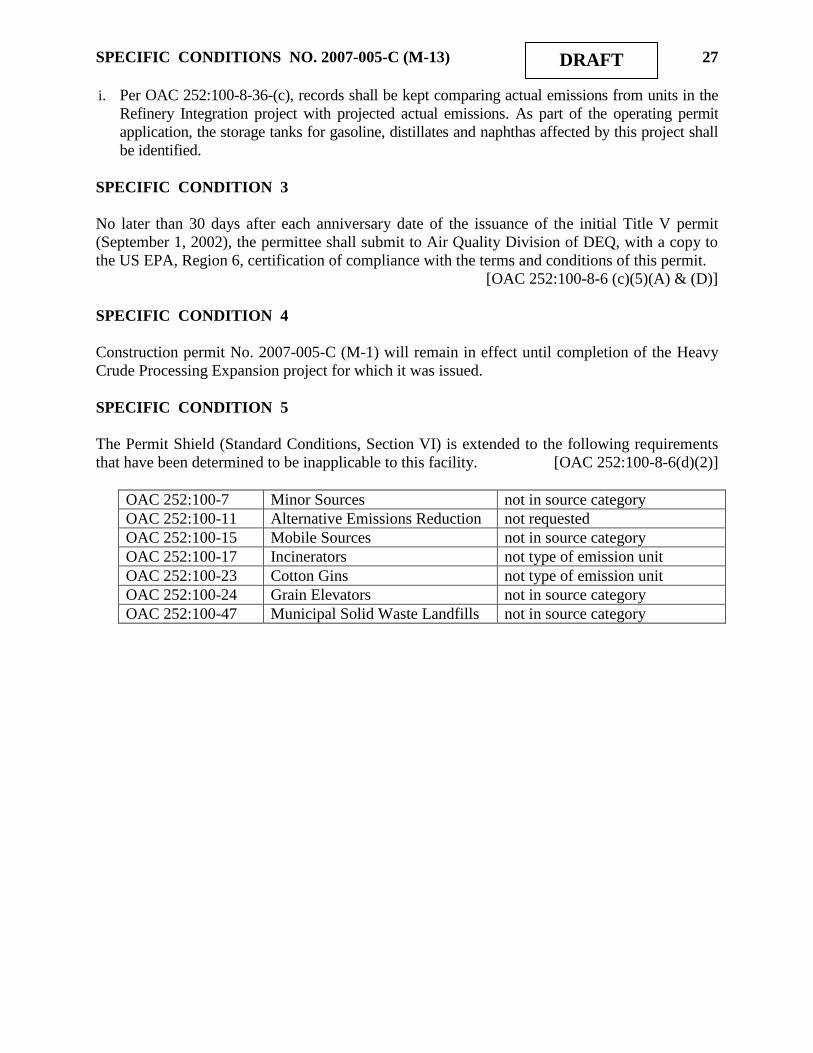
SPECIFIC CONDITIONS NO. 2007-005-C (M-13) 27 DRAFT
i. Per OAC 252:100-8-36-(c), records shall be kept comparing actual emissions from units in the
Refinery Integration project with projected actual emissions. As part of the operating permit
application, the storage tanks for gasoline, distillates and naphthas affected by this project shall
be identified.
SPECIFIC CONDITION 3
No later than 30 days after each anniversary date of the issuance of the initial Title V permit
(September 1, 2002), the permittee shall submit to Air Quality Division of DEQ, with a copy to
the US EPA, Region 6, certification of compliance with the terms and conditions of this permit.
[OAC 252:100-8-6 (c)(5)(A) & (D)]
SPECIFIC CONDITION 4
Construction permit No. 2007-005-C (M-1) will remain in effect until completion of the Heavy
Crude Processing Expansion project for which it was issued.
SPECIFIC CONDITION 5
The Permit Shield (Standard Conditions, Section VI) is extended to the following requirements
that have been determined to be inapplicable to this facility. [OAC 252:100-8-6(d)(2)]
OAC 252:100-7 Minor Sources not in source category
OAC 252:100-11 Alternative Emissions Reduction not requested
OAC 252:100-15 Mobile Sources not in source category
OAC 252:100-17 Incinerators not type of emission unit
OAC 252:100-23 Cotton Gins not type of emission unit
OAC 252:100-24 Grain Elevators not in source category
OAC 252:100-47 Municipal Solid Waste Landfills not in source category

MAJOR SOURCE AIR QUALITY PERMIT
STANDARD CONDITIONS
(July 21, 2009)
SECTION I. DUTY TO COMPLY
A. This is a permit to operate / construct this specific facility in accordance with the federal
Clean Air Act (42 U.S.C. 7401, et al.) and under the authority of the Oklahoma Clean Air Act
and the rules promulgated there under. [Oklahoma Clean Air Act, 27A O.S. § 2-5-112]
B. The issuing Authority for the permit is the Air Quality Division (AQD) of the Oklahoma
Department of Environmental Quality (DEQ). The permit does not relieve the holder of the
obligation to comply with other applicable federal, state, or local statutes, regulations, rules, or
ordinances. [Oklahoma Clean Air Act, 27A O.S. § 2-5-112]
C. The permittee shall comply with all conditions of this permit. Any permit noncompliance
shall constitute a violation of the Oklahoma Clean Air Act and shall be grounds for enforcement
action, permit termination, revocation and reissuance, or modification, or for denial of a permit
renewal application. All terms and conditions are enforceable by the DEQ, by the
Environmental Protection Agency (EPA), and by citizens under section 304 of the Federal Clean
Air Act (excluding state-only requirements). This permit is valid for operations only at the
specific location listed.
[40 C.F.R. §70.6(b), OAC 252:100-8-1.3 and OAC 252:100-8-6(a)(7)(A) and (b)(1)]
D. It shall not be a defense for a permittee in an enforcement action that it would have been
necessary to halt or reduce the permitted activity in order to maintain compliance with the
conditions of the permit. However, nothing in this paragraph shall be construed as precluding
consideration of a need to halt or reduce activity as a mitigating factor in assessing penalties for
noncompliance if the health, safety, or environmental impacts of halting or reducing operations
would be more serious than the impacts of continuing operations. [OAC 252:100-8-6(a)(7)(B)]
SECTION II. REPORTING OF DEVIATIONS FROM PERMIT TERMS
A. Any exceedance resulting from an emergency and/or posing an imminent and substantial
danger to public health, safety, or the environment shall be reported in accordance with Section
XIV (Emergencies). [OAC 252:100-8-6(a)(3)(C)(iii)(I) & (II)]
B. Deviations that result in emissions exceeding those allowed in this permit shall be reported
consistent with the requirements of OAC 252:100-9, Excess Emission Reporting Requirements.
[OAC 252:100-8-6(a)(3)(C)(iv)]
C. Every written report submitted under this section shall be certified as required by Section III
(Monitoring, Testing, Recordkeeping & Reporting), Paragraph F.
[OAC 252:100-8-6(a)(3)(C)(iv)]
MAJOR SOURCE STANDARD CONDITIONS July 21, 2009 2
SECTION III. MONITORING, TESTING, RECORDKEEPING & REPORTING
A. The permittee shall keep records as specified in this permit. These records, including
monitoring data and necessary support information, shall be retained on-site or at a nearby field
office for a period of at least five years from the date of the monitoring sample, measurement,
report, or application, and shall be made available for inspection by regulatory personnel upon
request. Support information includes all original strip-chart recordings for continuous
monitoring instrumentation, and copies of all reports required by this permit. Where appropriate,
the permit may specify that records may be maintained in computerized form.
[OAC 252:100-8-6 (a)(3)(B)(ii), OAC 252:100-8-6(c)(1), and OAC 252:100-8-6(c)(2)(B)]
B. Records of required monitoring shall include:
(1) the date, place and time of sampling or measurement;
(2) the date or dates analyses were performed;
(3) the company or entity which performed the analyses;
(4) the analytical techniques or methods used;
(5) the results of such analyses; and
(6) the operating conditions existing at the time of sampling or measurement.
[OAC 252:100-8-6(a)(3)(B)(i)]
C. No later than 30 days after each six (6) month period, after the date of the issuance of the
original Part 70 operating permit or alternative date as specifically identified in a subsequent Part
70 operating permit, the permittee shall submit to AQD a report of the results of any required
monitoring. All instances of deviations from permit requirements since the previous report shall
be clearly identified in the report. Submission of these periodic reports will satisfy any reporting
requirement of Paragraph E below that is duplicative of the periodic reports, if so noted on the
submitted report. [OAC 252:100-8-6(a)(3)(C)(i) and (ii)]
D. If any testing shows emissions in excess of limitations specified in this permit, the owner or
operator shall comply with the provisions of Section II (Reporting Of Deviations From Permit
Terms) of these standard conditions. [OAC 252:100-8-6(a)(3)(C)(iii)]
E. In addition to any monitoring, recordkeeping or reporting requirement specified in this
permit, monitoring and reporting may be required under the provisions of OAC 252:100-43,
Testing, Monitoring, and Recordkeeping, or as required by any provision of the Federal Clean
Air Act or Oklahoma Clean Air Act. [OAC 252:100-43]
F. Any Annual Certification of Compliance, Semi Annual Monitoring and Deviation Report,
Excess Emission Report, and Annual Emission Inventory submitted in accordance with this
permit shall be certified by a responsible official. This certification shall be signed by a
responsible official, and shall contain the following language: “I certify, based on information
and belief formed after reasonable inquiry, the statements and information in the document are
true, accurate, and complete.”
[OAC 252:100-8-5(f), OAC 252:100-8-6(a)(3)(C)(iv), OAC 252:100-8-6(c)(1), OAC
252:100-9-7(e), and OAC 252:100-5-2.1(f)]
G. Any owner or operator subject to the provisions of New Source Performance Standards
(“NSPS”) under 40 CFR Part 60 or National Emission Standards for Hazardous Air Pollutants
(“NESHAPs”) under 40 CFR Parts 61 and 63 shall maintain a file of all measurements and other

MAJOR SOURCE STANDARD CONDITIONS July 21, 2009 3
information required by the applicable general provisions and subpart(s). These records shall be
maintained in a permanent file suitable for inspection, shall be retained for a period of at least
five years as required by Paragraph A of this Section, and shall include records of the occurrence
and duration of any start-up, shutdown, or malfunction in the operation of an affected facility,
any malfunction of the air pollution control equipment; and any periods during which a
continuous monitoring system or monitoring device is inoperative.
[40 C.F.R. §§60.7 and 63.10, 40 CFR Parts 61, Subpart A, and OAC 252:100, Appendix Q]
H. The permittee of a facility that is operating subject to a schedule of compliance shall submit
to the DEQ a progress report at least semi-annually. The progress reports shall contain dates for
achieving the activities, milestones or compliance required in the schedule of compliance and the
dates when such activities, milestones or compliance was achieved. The progress reports shall
also contain an explanation of why any dates in the schedule of compliance were not or will not
be met, and any preventive or corrective measures adopted. [OAC 252:100-8-6(c)(4)]
I. All testing must be conducted under the direction of qualified personnel by methods
approved by the Division Director. All tests shall be made and the results calculated in
accordance with standard test procedures. The use of alternative test procedures must be
approved by EPA. When a portable analyzer is used to measure emissions it shall be setup,
calibrated, and operated in accordance with the manufacturer‟s instructions and in accordance
with a protocol meeting the requirements of the “AQD Portable Analyzer Guidance” document
or an equivalent method approved by Air Quality.
[OAC 252:100-8-6(a)(3)(A)(iv), and OAC 252:100-43]
J. The reporting of total particulate matter emissions as required in Part 7 of OAC 252:100-8
(Permits for Part 70 Sources), OAC 252:100-19 (Control of Emission of Particulate Matter), and
OAC 252:100-5 (Emission Inventory), shall be conducted in accordance with applicable testing
or calculation procedures, modified to include back-half condensables, for the concentration of
particulate matter less than 10 microns in diameter (PM10). NSPS may allow reporting of only
particulate matter emissions caught in the filter (obtained using Reference Method 5).
K. The permittee shall submit to the AQD a copy of all reports submitted to the EPA as required
by 40 C.F.R. Part 60, 61, and 63, for all equipment constructed or operated under this permit
subject to such standards. [OAC 252:100-8-6(c)(1) and OAC 252:100, Appendix Q]
SECTION IV. COMPLIANCE CERTIFICATIONS
A. No later than 30 days after each anniversary date of the issuance of the original Part 70
operating permit or alternative date as specifically identified in a subsequent Part 70 operating
permit, the permittee shall submit to the AQD, with a copy to the US EPA, Region 6, a
certification of compliance with the terms and conditions of this permit and of any other
applicable requirements which have become effective since the issuance of this permit.
[OAC 252:100-8-6(c)(5)(A), and (D)]
B. The compliance certification shall describe the operating permit term or condition that is the
basis of the certification; the current compliance status; whether compliance was continuous or
intermittent; the methods used for determining compliance, currently and over the reporting
period. The compliance certification shall also include such other facts as the permitting
authority may require to determine the compliance status of the source.

MAJOR SOURCE STANDARD CONDITIONS July 21, 2009 4
[OAC 252:100-8-6(c)(5)(C)(i)-(v)]
C. The compliance certification shall contain a certification by a responsible official as to the
results of the required monitoring. This certification shall be signed by a responsible official,
and shall contain the following language: “I certify, based on information and belief formed
after reasonable inquiry, the statements and information in the document are true, accurate, and
complete.” [OAC 252:100-8-5(f) and OAC 252:100-8-6(c)(1)]
D. Any facility reporting noncompliance shall submit a schedule of compliance for emissions
units or stationary sources that are not in compliance with all applicable requirements. This
schedule shall include a schedule of remedial measures, including an enforceable sequence of
actions with milestones, leading to compliance with any applicable requirements for which the
emissions unit or stationary source is in noncompliance. This compliance schedule shall
resemble and be at least as stringent as that contained in any judicial consent decree or
administrative order to which the emissions unit or stationary source is subject. Any such
schedule of compliance shall be supplemental to, and shall not sanction noncompliance with, the
applicable requirements on which it is based, except that a compliance plan shall not be required
for any noncompliance condition which is corrected within 24 hours of discovery.
[OAC 252:100-8-5(e)(8)(B) and OAC 252:100-8-6(c)(3)]
SECTION V. REQUIREMENTS THAT BECOME APPLICABLE DURING THE
PERMIT TERM
The permittee shall comply with any additional requirements that become effective during the
permit term and that are applicable to the facility. Compliance with all new requirements shall
be certified in the next annual certification. [OAC 252:100-8-6(c)(6)]
SECTION VI. PERMIT SHIELD
A. Compliance with the terms and conditions of this permit (including terms and conditions
established for alternate operating scenarios, emissions trading, and emissions averaging, but
excluding terms and conditions for which the permit shield is expressly prohibited under OAC
252:100-8) shall be deemed compliance with the applicable requirements identified and included
in this permit. [OAC 252:100-8-6(d)(1)]
B. Those requirements that are applicable are listed in the Standard Conditions and the Specific
Conditions of this permit. Those requirements that the applicant requested be determined as not
applicable are summarized in the Specific Conditions of this permit. [OAC 252:100-8-6(d)(2)]
SECTION VII. ANNUAL EMISSIONS INVENTORY & FEE PAYMENT
The permittee shall file with the AQD an annual emission inventory and shall pay annual fees
based on emissions inventories. The methods used to calculate emissions for inventory purposes
shall be based on the best available information accepted by AQD.
[OAC 252:100-5-2.1, OAC 252:100-5-2.2, and OAC 252:100-8-6(a)(8)]

MAJOR SOURCE STANDARD CONDITIONS July 21, 2009 5
SECTION VIII. TERM OF PERMIT
A. Unless specified otherwise, the term of an operating permit shall be five years from the date
of issuance. [OAC 252:100-8-6(a)(2)(A)]
B. A source‟s right to operate shall terminate upon the expiration of its permit unless a timely
and complete renewal application has been submitted at least 180 days before the date of
expiration. [OAC 252:100-8-7.1(d)(1)]
C. A duly issued construction permit or authorization to construct or modify will terminate and
become null and void (unless extended as provided in OAC 252:100-8-1.4(b)) if the construction
is not commenced within 18 months after the date the permit or authorization was issued, or if
work is suspended for more than 18 months after it is commenced. [OAC 252:100-8-1.4(a)]
D. The recipient of a construction permit shall apply for a permit to operate (or modified
operating permit) within 180 days following the first day of operation. [OAC 252:100-8-4(b)(5)]
SECTION IX. SEVERABILITY
The provisions of this permit are severable and if any provision of this permit, or the application
of any provision of this permit to any circumstance, is held invalid, the application of such
provision to other circumstances, and the remainder of this permit, shall not be affected thereby.
[OAC 252:100-8-6 (a)(6)]
SECTION X. PROPERTY RIGHTS
A. This permit does not convey any property rights of any sort, or any exclusive privilege.
[OAC 252:100-8-6(a)(7)(D)]
B. This permit shall not be considered in any manner affecting the title of the premises upon
which the equipment is located and does not release the permittee from any liability for damage
to persons or property caused by or resulting from the maintenance or operation of the equipment
for which the permit is issued. [OAC 252:100-8-6(c)(6)]
SECTION XI. DUTY TO PROVIDE INFORMATION
A. The permittee shall furnish to the DEQ, upon receipt of a written request and within sixty
(60) days of the request unless the DEQ specifies another time period, any information that the
DEQ may request to determine whether cause exists for modifying, reopening, revoking,
reissuing, terminating the permit or to determine compliance with the permit. Upon request, the
permittee shall also furnish to the DEQ copies of records required to be kept by the permit.
[OAC 252:100-8-6(a)(7)(E)]
B. The permittee may make a claim of confidentiality for any information or records submitted
pursuant to 27A O.S. § 2-5-105(18). Confidential information shall be clearly labeled as such
and shall be separable from the main body of the document such as in an attachment.
[OAC 252:100-8-6(a)(7)(E)]
MAJOR SOURCE STANDARD CONDITIONS July 21, 2009 6
C. Notification to the AQD of the sale or transfer of ownership of this facility is required and
shall be made in writing within thirty (30) days after such sale or transfer.
[Oklahoma Clean Air Act, 27A O.S. § 2-5-112(G)]
SECTION XII. REOPENING, MODIFICATION & REVOCATION
A. The permit may be modified, revoked, reopened and reissued, or terminated for cause.
Except as provided for minor permit modifications, the filing of a request by the permittee for a
permit modification, revocation and reissuance, termination, notification of planned changes, or
anticipated noncompliance does not stay any permit condition.
[OAC 252:100-8-6(a)(7)(C) and OAC 252:100-8-7.2(b)]
B. The DEQ will reopen and revise or revoke this permit prior to the expiration date in the
following circumstances: [OAC 252:100-8-7.3 and OAC 252:100-8-7.4(a)(2)]
(1) Additional requirements under the Clean Air Act become applicable to a major source
category three or more years prior to the expiration date of this permit. No such
reopening is required if the effective date of the requirement is later than the expiration
date of this permit.
(2) The DEQ or the EPA determines that this permit contains a material mistake or that the
permit must be revised or revoked to assure compliance with the applicable requirements.
(3) The DEQ or the EPA determines that inaccurate information was used in establishing the
emission standards, limitations, or other conditions of this permit. The DEQ may revoke
and not reissue this permit if it determines that the permittee has submitted false or
misleading information to the DEQ.
(4) DEQ determines that the permit should be amended under the discretionary reopening
provisions of OAC 252:100-8-7.3(b).
C. The permit may be reopened for cause by EPA, pursuant to the provisions of OAC 100-8-
7.3(d). [OAC 100-8-7.3(d)]
D. The permittee shall notify AQD before making changes other than those described in Section
XVIII (Operational Flexibility), those qualifying for administrative permit amendments, or those
defined as an Insignificant Activity (Section XVI) or Trivial Activity (Section XVII). The
notification should include any changes which may alter the status of a “grandfathered source,”
as defined under AQD rules. Such changes may require a permit modification.
[OAC 252:100-8-7.2(b) and OAC 252:100-5-1.1]
E. Activities that will result in air emissions that exceed the trivial/insignificant levels and that
are not specifically approved by this permit are prohibited. [OAC 252:100-8-6(c)(6)]
SECTION XIII. INSPECTION & ENTRY
A. Upon presentation of credentials and other documents as may be required by law, the
permittee shall allow authorized regulatory officials to perform the following (subject to the
permittee's right to seek confidential treatment pursuant to 27A O.S. Supp. 1998, § 2-5-105(18)
for confidential information submitted to or obtained by the DEQ under this section):

MAJOR SOURCE STANDARD CONDITIONS July 21, 2009 7
(1) enter upon the permittee's premises during reasonable/normal working hours where a
source is located or emissions-related activity is conducted, or where records must be
kept under the conditions of the permit;
(2) have access to and copy, at reasonable times, any records that must be kept under the
conditions of the permit;
(3) inspect, at reasonable times and using reasonable safety practices, any facilities,
equipment (including monitoring and air pollution control equipment), practices, or
operations regulated or required under the permit; and
(4) as authorized by the Oklahoma Clean Air Act, sample or monitor at reasonable times
substances or parameters for the purpose of assuring compliance with the permit.
[OAC 252:100-8-6(c)(2)]
SECTION XIV. EMERGENCIES
A. Any exceedance resulting from an emergency shall be reported to AQD promptly but no later
than 4:30 p.m. on the next working day after the permittee first becomes aware of the
exceedance. This notice shall contain a description of the emergency, the probable cause of the
exceedance, any steps taken to mitigate emissions, and corrective actions taken.
[OAC 252:100-8-6 (a)(3)(C)(iii)(I) and (IV)]
B. Any exceedance that poses an imminent and substantial danger to public health, safety, or the
environment shall be reported to AQD as soon as is practicable; but under no circumstance shall
notification be more than 24 hours after the exceedance. [OAC 252:100-8-6(a)(3)(C)(iii)(II)]
C. An "emergency" means any situation arising from sudden and reasonably unforeseeable
events beyond the control of the source, including acts of God, which situation requires
immediate corrective action to restore normal operation, and that causes the source to exceed a
technology-based emission limitation under this permit, due to unavoidable increases in
emissions attributable to the emergency. An emergency shall not include noncompliance to the
extent caused by improperly designed equipment, lack of preventive maintenance, careless or
improper operation, or operator error. [OAC 252:100-8-2]
D. The affirmative defense of emergency shall be demonstrated through properly signed,
contemporaneous operating logs or other relevant evidence that: [OAC 252:100-8-6 (e)(2)]
(1) an emergency occurred and the permittee can identify the cause or causes of the
emergency;
(2) the permitted facility was at the time being properly operated;
(3) during the period of the emergency the permittee took all reasonable steps to minimize
levels of emissions that exceeded the emission standards or other requirements in this
permit.
E. In any enforcement proceeding, the permittee seeking to establish the occurrence of an
emergency shall have the burden of proof. [OAC 252:100-8-6(e)(3)]
F. Every written report or document submitted under this section shall be certified as required
by Section III (Monitoring, Testing, Recordkeeping & Reporting), Paragraph F.
[OAC 252:100-8-6(a)(3)(C)(iv)]

MAJOR SOURCE STANDARD CONDITIONS July 21, 2009 8
SECTION XV. RISK MANAGEMENT PLAN
The permittee, if subject to the provision of Section 112(r) of the Clean Air Act, shall develop
and register with the appropriate agency a risk management plan by June 20, 1999, or the
applicable effective date. [OAC 252:100-8-6(a)(4)]
SECTION XVI. INSIGNIFICANT ACTIVITIES
Except as otherwise prohibited or limited by this permit, the permittee is hereby authorized to
operate individual emissions units that are either on the list in Appendix I to OAC Title 252,
Chapter 100, or whose actual calendar year emissions do not exceed any of the limits below.
Any activity to which a State or Federal applicable requirement applies is not insignificant even
if it meets the criteria below or is included on the insignificant activities list.
(1) 5 tons per year of any one criteria pollutant.
(2) 2 tons per year for any one hazardous air pollutant (HAP) or 5 tons per year for an
aggregate of two or more HAP's, or 20 percent of any threshold less than 10 tons per year
for single HAP that the EPA may establish by rule.
[OAC 252:100-8-2 and OAC 252:100, Appendix I]
SECTION XVII. TRIVIAL ACTIVITIES
Except as otherwise prohibited or limited by this permit, the permittee is hereby authorized to
operate any individual or combination of air emissions units that are considered inconsequential
and are on the list in Appendix J. Any activity to which a State or Federal applicable
requirement applies is not trivial even if included on the trivial activities list.
[OAC 252:100-8-2 and OAC 252:100, Appendix J]
SECTION XVIII. OPERATIONAL FLEXIBILITY
A. A facility may implement any operating scenario allowed for in its Part 70 permit without the
need for any permit revision or any notification to the DEQ (unless specified otherwise in the
permit). When an operating scenario is changed, the permittee shall record in a log at the facility
the scenario under which it is operating. [OAC 252:100-8-6(a)(10) and (f)(1)]
B. The permittee may make changes within the facility that:
(1) result in no net emissions increases,
(2) are not modifications under any provision of Title I of the federal Clean Air Act, and
(3) do not cause any hourly or annual permitted emission rate of any existing emissions unit
to be exceeded;
provided that the facility provides the EPA and the DEQ with written notification as required
below in advance of the proposed changes, which shall be a minimum of seven (7) days, or
twenty four (24) hours for emergencies as defined in OAC 252:100-8-6 (e). The permittee, the
DEQ, and the EPA shall attach each such notice to their copy of the permit. For each such
change, the written notification required above shall include a brief description of the change
within the permitted facility, the date on which the change will occur, any change in emissions,

MAJOR SOURCE STANDARD CONDITIONS July 21, 2009 9
and any permit term or condition that is no longer applicable as a result of the change. The
permit shield provided by this permit does not apply to any change made pursuant to this
paragraph. [OAC 252:100-8-6(f)(2)]
SECTION XIX. OTHER APPLICABLE & STATE-ONLY REQUIREMENTS
A. The following applicable requirements and state-only requirements apply to the facility
unless elsewhere covered by a more restrictive requirement:
(1) Open burning of refuse and other combustible material is prohibited except as authorized
in the specific examples and under the conditions listed in the Open Burning Subchapter.
[OAC 252:100-13]
(2) No particulate emissions from any fuel-burning equipment with a rated heat input of 10
MMBTUH or less shall exceed 0.6 lb/MMBTU. [OAC 252:100-19]
(3) For all emissions units not subject to an opacity limit promulgated under 40 C.F.R., Part
60, NSPS, no discharge of greater than 20% opacity is allowed except for:
[OAC 252:100-25]
(a) Short-term occurrences which consist of not more than one six-minute period in any
consecutive 60 minutes, not to exceed three such periods in any consecutive 24 hours.
In no case shall the average of any six-minute period exceed 60% opacity;
(b) Smoke resulting from fires covered by the exceptions outlined in OAC 252:100-13-7;
(c) An emission, where the presence of uncombined water is the only reason for failure
to meet the requirements of OAC 252:100-25-3(a); or
(d) Smoke generated due to a malfunction in a facility, when the source of the fuel
producing the smoke is not under the direct and immediate control of the facility and
the immediate constriction of the fuel flow at the facility would produce a hazard to
life and/or property.
(4) No visible fugitive dust emissions shall be discharged beyond the property line on which
the emissions originate in such a manner as to damage or to interfere with the use of
adjacent properties, or cause air quality standards to be exceeded, or interfere with the
maintenance of air quality standards. [OAC 252:100-29]
(5) No sulfur oxide emissions from new gas-fired fuel-burning equipment shall exceed 0.2
lb/MMBTU. No existing source shall exceed the listed ambient air standards for sulfur
dioxide. [OAC 252:100-31]
(6) Volatile Organic Compound (VOC) storage tanks built after December 28, 1974, and
with a capacity of 400 gallons or more storing a liquid with a vapor pressure of 1.5 psia
or greater under actual conditions shall be equipped with a permanent submerged fill pipe
or with a vapor-recovery system. [OAC 252:100-37-15(b)]
(7) All fuel-burning equipment shall at all times be properly operated and maintained in a
manner that will minimize emissions of VOCs. [OAC 252:100-37-36]

MAJOR SOURCE STANDARD CONDITIONS July 21, 2009 10
SECTION XX. STRATOSPHERIC OZONE PROTECTION
A. The permittee shall comply with the following standards for production and consumption of
ozone-depleting substances: [40 CFR 82, Subpart A]
(1) Persons producing, importing, or placing an order for production or importation of certain
class I and class II substances, HCFC-22, or HCFC-141b shall be subject to the
requirements of §82.4;
(2) Producers, importers, exporters, purchasers, and persons who transform or destroy certain
class I and class II substances, HCFC-22, or HCFC-141b are subject to the recordkeeping
requirements at §82.13; and
(3) Class I substances (listed at Appendix A to Subpart A) include certain CFCs, Halons,
HBFCs, carbon tetrachloride, trichloroethane (methyl chloroform), and bromomethane
(Methyl Bromide). Class II substances (listed at Appendix B to Subpart A) include
HCFCs.
B. If the permittee performs a service on motor (fleet) vehicles when this service involves an
ozone-depleting substance refrigerant (or regulated substitute substance) in the motor vehicle air
conditioner (MVAC), the permittee is subject to all applicable requirements. Note: The term
“motor vehicle” as used in Subpart B does not include a vehicle in which final assembly of the
vehicle has not been completed. The term “MVAC” as used in Subpart B does not include the
air-tight sealed refrigeration system used as refrigerated cargo, or the system used on passenger
buses using HCFC-22 refrigerant. [40 CFR 82, Subpart B]
C. The permittee shall comply with the following standards for recycling and emissions
reduction except as provided for MVACs in Subpart B: [40 CFR 82, Subpart F]
(1) Persons opening appliances for maintenance, service, repair, or disposal must comply
with the required practices pursuant to § 82.156;
(2) Equipment used during the maintenance, service, repair, or disposal of appliances must
comply with the standards for recycling and recovery equipment pursuant to § 82.158;
(3) Persons performing maintenance, service, repair, or disposal of appliances must be
certified by an approved technician certification program pursuant to § 82.161;
(4) Persons disposing of small appliances, MVACs, and MVAC-like appliances must comply
with record-keeping requirements pursuant to § 82.166;
(5) Persons owning commercial or industrial process refrigeration equipment must comply
with leak repair requirements pursuant to § 82.158; and
(6) Owners/operators of appliances normally containing 50 or more pounds of refrigerant
must keep records of refrigerant purchased and added to such appliances pursuant to §
82.166.
SECTION XXI. TITLE V APPROVAL LANGUAGE
A. DEQ wishes to reduce the time and work associated with permit review and, wherever it is
not inconsistent with Federal requirements, to provide for incorporation of requirements
established through construction permitting into the Source‟s Title V permit without causing
redundant review. Requirements from construction permits may be incorporated into the Title V
permit through the administrative amendment process set forth in OAC 252:100-8-7.2(a) only if
the following procedures are followed:

MAJOR SOURCE STANDARD CONDITIONS July 21, 2009 11
(1) The construction permit goes out for a 30-day public notice and comment using the
procedures set forth in 40 C.F.R. § 70.7(h)(1). This public notice shall include notice to
the public that this permit is subject to EPA review, EPA objection, and petition to
EPA, as provided by 40 C.F.R. § 70.8; that the requirements of the construction permit
will be incorporated into the Title V permit through the administrative amendment
process; that the public will not receive another opportunity to provide comments when
the requirements are incorporated into the Title V permit; and that EPA review, EPA
objection, and petitions to EPA will not be available to the public when requirements
from the construction permit are incorporated into the Title V permit.
(2) A copy of the construction permit application is sent to EPA, as provided by 40 CFR §
70.8(a)(1).
(3) A copy of the draft construction permit is sent to any affected State, as provided by 40
C.F.R. § 70.8(b).
(4) A copy of the proposed construction permit is sent to EPA for a 45-day review period
as provided by 40 C.F.R.§ 70.8(a) and (c).
(5) The DEQ complies with 40 C.F.R. § 70.8(c) upon the written receipt within the 45-day
comment period of any EPA objection to the construction permit. The DEQ shall not
issue the permit until EPA‟s objections are resolved to the satisfaction of EPA.
(6) The DEQ complies with 40 C.F.R. § 70.8(d).
(7) A copy of the final construction permit is sent to EPA as provided by 40 CFR § 70.8(a).
(8) The DEQ shall not issue the proposed construction permit until any affected State and
EPA have had an opportunity to review the proposed permit, as provided by these
permit conditions.
(9) Any requirements of the construction permit may be reopened for cause after
incorporation into the Title V permit by the administrative amendment process, by
DEQ as provided in OAC 252:100-8-7.3(a), (b), and (c), and by EPA as provided in 40
C.F.R. § 70.7(f) and (g).
(10) The DEQ shall not issue the administrative permit amendment if performance tests fail
to demonstrate that the source is operating in substantial compliance with all permit
requirements.
B. To the extent that these conditions are not followed, the Title V permit must go through the
Title V review process.
SECTION XXII. CREDIBLE EVIDENCE
For the purpose of submitting compliance certifications or establishing whether or not a person
has violated or is in violation of any provision of the Oklahoma implementation plan, nothing
shall preclude the use, including the exclusive use, of any credible evidence or information,
relevant to whether a source would have been in compliance with applicable requirements if the
appropriate performance or compliance test or procedure had been performed.
[OAC 252:100-43-6]
Jim Resinger, Refinery Manager
Holly Refining & Marketing – Tulsa, LLC
1700 S. Union Avenue
Tulsa, OK 74107
Re: Part 70 Permit No. 2007-005-C (M-13)
Tulsa Refinery Integration Project
Dear Mr. Resinger:
Enclosed is the modified Title V permit authorizing construction of the referenced facility.
Please note that this permit is issued subject to certain standard and specific conditions that are
attached.
Also note that you are required to annually submit an emission inventory for this facility. An
emission inventory must be completed on approved AQD forms and submitted (hardcopy or
electronically) by April 1st of every year. Any questions concerning the form or submittal
process should be referred to the Emission Inventory Staff at 405-702-4100.
Thank you for your cooperation in this matter. If we may be of further service, please contact
our office at (918) 293-1600. Air Quality personnel are located in the DEQ Regional Office at
Tulsa, 3105 E. Skelly Drive, Suite 200, Tulsa, OK, 74105.
Sincerely,
David S. Schutz, P.E.
New Source Permits Section
Air Quality Division

PART 70 PERMIT
AIR QUALITY DIVISION
STATE OF OKLAHOMA
DEPARTMENT OF ENVIRONMENTAL QUALITY
707 N. ROBINSON, SUITE 4100
P.O. BOX 1677
OKLAHOMA CITY, OKLAHOMA 73101-1677
Permit No. 2007-005-C (M-13)
Holly Refining & Marketing – Tulsa, LLC,
having complied with the requirements of the law, is hereby granted permission to
construct modifications within the boundaries of the Tulsa Refinery, 902 W. 25th
Street,
Tulsa, Tulsa County, Oklahoma,
subject to standard conditions dated July 21, 2009, and specific conditions, both attached.
In the absence of commencement of construction, this permit shall expire 18 months from
the date below, except as authorized under Section VIII of the Standard Conditions.
_________________________________
Division Director, Date
Air Quality Division