Embed Size (px)
Citation preview

Forbes Marshall Forbes Marshall Arca Forbes Marshall Codel Krohne Marshall Spirax Marshall Forbes Vyncke
Refinery and Petrochemical Plants
Machine Condition Monitoring System Application Note

Need for Machine Monitoring System in a refinery plant
Monitoring the running condition of plant machinery is, without a doubt, important. Most efforts to move away from Preventive Maintenance (time based maintenance) to Predictive Maintenance (also called condition-based maintenance) have come about in the last 15 years, particularly in large industrial plants. By monitoring plant machinery, one can plan outages and repairs and save a lot of money. Unplanned outages, resulting from machinery failure, are very costly. The outages are usually longer and the repair cost is often higher because damaged parts have to be replaced or repaired instead of replacing just worn out parts.
Objectives of Vibration Monitoring
• Effective for many root causes i.e. imbalance, misalignment, abnormal roller bearing, abnormal sleeve bearing, abnormal speed reducer, looseness etc.
• Preventing unscheduled downtime
• Extending machine usable time
• Reducing energy costs
• Reducing downtime when machine is down
• Preventing failures
Gases
Gasoline
Light distillates
Intermediate distillates
Heavy distillates
Residues
Fractioning Tower
Decr
easin
g Te
mpe
ratu
re
Crude Oil Furnace
1 to 4 Carbon atoms
5 to 12 Carbon atoms
12 to 16 Carbon atoms
15 to 18 Carbon atoms
16 to 20 Carbon atoms
More than 20 Carbon atoms
Less than 40ºC
40ºC - 200ºC
200ºC - 300ºC
250ºC - 350ºC
300ºC - 370ºC
Greater than 370ºC
What is a refinery?
A refinery is a facility that processes crude oil. The basic process unit in a refinery is a crude oil distillation unit, which splits crude oil into various fractions through a process of heating and condensing.

Advantage of Vibration Monitoring for machine failure detection
Centrifugal compressor / Reciprocating compressorThese systems include air and gas compressors, coolers, receivers and dryers, controls, distribution piping, and blowers provide air to operate air-powered tools, to regenerate catalyst, and to supply heaters and other operations. Predictive maintenance of these compressors is must during start up.
Turbo ExpandersHot flue gases pass through the expander recovering power from the process pressure. The low-pressure gas exiting the expander is piped to boiler heat exchangers for final power recovery. 'Burning' an expander is a very expensive exercise and there is a need to plan maintenance proactively.
Various Pumps Pumps play a vital role in petroleum industry without which a plant or process can't function. With critical machinery being at the heart of the process it requires on-line condition monitoring to continually record data from the machine. Measurements such as casing vibration and displacement, shaft axial and radial displacement, are taken where possible. These values are then fed back to a machinery management software package which is capable of trending the historical data and providing the operators with information such as performance data and even predict faults and provide diagnosis of failures before they happen.
Cooling Tower FansCooling towers at a refinery remove heat from process water, either by allowing air to pass perpendicular to the flow of water, or by allowing the water to cascade down through a tower. Most common component failures are due to failure of fan blades, misalignment of gear box, or unbalance of motor which causes damage to cooling tower systems. Forbes Marshall Shinkawa Monitoring systems, monitor the health of inaccessible machine components of cooling towers by permanently mounting sensors on gearboxes and motors.
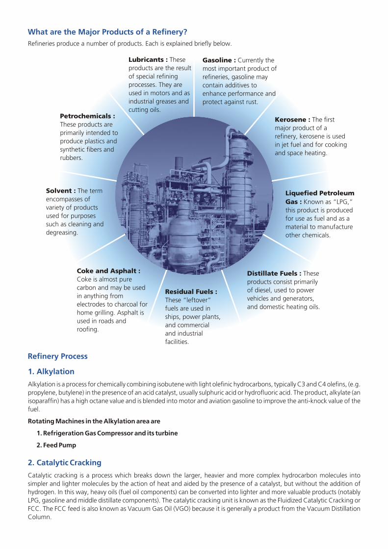
What are the Major Products of a Refinery?Refineries produce a number of products. Each is explained briefly below.
Gasoline : Currently the most important product of refineries, gasoline may contain additives to enhance performance and protect against rust.
Kerosene : The first major product of a refinery, kerosene is used in jet fuel and for cooking and space heating.
Liquefied Petroleum Gas : Known as “LPG,” this product is produced for use as fuel and as a material to manufacture other chemicals.
Distillate Fuels : These products consist primarily of diesel, used to power vehicles and generators, and domestic heating oils.
Residual Fuels : These “leftover” fuels are used in ships, power plants, and commercial and industrial facilities.
Coke and Asphalt : Coke is almost pure carbon and may be used in anything from electrodes to charcoal for home grilling. Asphalt is used in roads and roofing.
Solvent : The term encompasses of variety of products used for purposes such as cleaning and degreasing.
Petrochemicals : These products are primarily intended to produce plastics and synthetic fibers and rubbers.
Lubricants : These products are the result of special refining processes. They are used in motors and as industrial greases and cutting oils.
1. Alkylation
2. Catalytic Cracking
Alkylation is a process for chemically combining isobutene with light olefinic hydrocarbons, typically C3 and C4 olefins, (e.g. propylene, butylene) in the presence of an acid catalyst, usually sulphuric acid or hydrofluoric acid. The product, alkylate (an isoparaffin) has a high octane value and is blended into motor and aviation gasoline to improve the anti-knock value of the fuel.
Rotating Machines in the Alkylation area are
1. Refrigeration Gas Compressor and its turbine
2. Feed Pump
Catalytic cracking is a process which breaks down the larger, heavier and more complex hydrocarbon molecules into simpler and lighter molecules by the action of heat and aided by the presence of a catalyst, but without the addition of hydrogen. In this way, heavy oils (fuel oil components) can be converted into lighter and more valuable products (notably LPG, gasoline and middle distillate components). The catalytic cracking unit is known as the Fluidized Catalytic Cracking or FCC. The FCC feed is also known as Vacuum Gas Oil (VGO) because it is generally a product from the Vacuum Distillation Column.
Refinery Process

Refinery Process Schematic
Amine Treating Refinery Fuel
H S2
Fuel Gas
Merox Treaters
Other Gases
Gas H2
LPGButanes H S From2
Sour Water Stripper
Hydrotreater IsomerizationPlant
H2Gas
Hydrotreater
H2Gas H2Gas
CatalyticReformer
Reformate
Gas
olin
e Bl
endi
ng P
ool
Atm
osph
rio D
istilla
tion
H2Gas
Hydrocracked Gasoline
Diesel OilGas
Hydr
ocra
cker
Jet Fueland / orKerosene
Diesel Oil
Gas
Light
Naphtha
Naphtha
Heavy
Jet FuelKerosene
Oil
Crude
Hydrotreater
H2Gas
Diesel Oil
Gas OilAtmospheric
Gas Oil
Heavy Vacuum
H2Gas
GasEvacuated
non-condensibles
Atm
osph
eris
Botto
ms
LightVacuum
Gas Oil
Gas Oil
HeavyVacuum
Vacuum Residuum
Gas
Air AsphaltAsphaltBlowing
Dela
yed
Coke
r
Coker Gas Oil
Coker Naphtha
Petroleum Coke
(after hydrotreating and reforming)
FCC Gas Oil
FCC GasolineNaphthaHydrotreater
Alkylation
H2Gas
Alkylatei-ButaneButenesPentenes
Fuel Oil
FCC FeedHydrotreater
Sulfur
Isomerate
H S to Sulfur Plant2
SourWaters
Syeam
StrippedWater
Sour
Wat
erSt
eam
Stri
pper
Claus SulfurPlant
Gas Processing
Merox Treater
Fluid
Cat
alyt
icCr
acke
r (FC
C)
Vacu
um
Dist
illatio
n
CO2
H2
Natural Gas
Steam
HydrogenSynthesisFinished products are shown in blue
Sour waters are derived from various distillation towerreflus drums in the refineryThe “other gases” entening the gas processing unitincludes all the gas streams from the variousprocess units
A. Fluidized Catalytic Cracking (FCC)FCC is a process whose objective is to convert low value gas oils to valuable products (naphtha and diesel) and slurry oil. Primary Process Technique :-
Catalytic cracking increases H/C ratio by carbon rejection in a continuous process.Process steps:
• Gas oil feed is dispersed into the bottom of the riser using steam• Thermal cracking occurs on the surface of the catalyst• Disengaging drum separates spent catalyst from product vapors• Steam strips residue hydrocarbons from spent catalyst• Air burns away the carbon film from the catalyst in either a “partial-burn” or “full-burn” mode of operation• Regenerated catalyst enters bottom of riser-reactor
Rotating Machine details in Catalytic Cracking area are:1. Air Blower Motor2. Heat pumps compressor (turbine driven), wet gas compressor and turbine3. Expander

B. Hydrogen Plant
C. Vacuum Gas Oil (VGO)
3. Delayed Coking
4. Distillation (atmospheric and vacuum)
The most commonly used method of hydrogen production is the steam reforming process. The main process consists of the reaction of steam with a hydrocarbon over a catalyst at around 750-800°C temperature, in order to form hydrogen and carbon oxides. The whole process starts with:
• Purification of the raw material, in which toxins, like, sulphur and chloride are removed ensuring maximum life of the downstream steam reforming and other catalysts.
• Steam Reformation is the next step which can also be stated as the essence of the working process of a hydrogen gas plant, involves the main hydrogen-producing reaction. [There are numerous process designs for the 'Steam Reforming Reaction'. The conventional design is 'High Pressure and High Temperature Process Design', which is basically used by refineries to generate Hydrogen. Another design is the 'Low Pressure Design, which is also rich in carbon-di-oxide and is primarily used for direct reduction plants].
• High Temperature Shift and Low Temperature Shift, the third step and consists of the reaction of carbon monoxide with steam in two phases, namely high temperature and low temperature. This reaction results in carbon dioxide and additional hydrogen
• The Purification Process, this is the final step which produces 99.99% product hydrogen and an-off gas by using Pressure Swing Absorption unit (PSA).
Rotating Machine details in Catalytic Cracking area are: Feed Gas and Make-up gas Compressors
Primary objective of VGO is to recover valuable gas oils from reduced crude via vacuum distillation.
• Primary Process Technique:– Reduce the hydrocarbon partial pressure via vacuum and stripping steam
• Process steps:– Heat the reduced crude to the desired temperature using fired heaters– Flash the reduced crude in the vacuum distillation column– Utilize pump around cooling loops to create internal liquid reflux– Product draws are top, sides, and bottom
Rotating Machine details in Catalytic Cracking area are:
1. ID Fan and FD Fan
2. Recycle gas compressor (turbine driven)
3. Various critical pumps.
Delayed coking is a high severity "bottom of the barrel processing" scheme by which heavy crude oil fractions can be thermally decomposed under certain conditions or elevated temperatures to produce a mixture of lighter oils and petroleum coke. The light oils can be processed further in other refinery units or blended into products. The coke can be used either as a fuel or in other metallurgical applications such as the manufacture of steel or aluminum.
Rotating Machine details in Delayed Coking area are:
1. Heater charge and other critical pumps
2. Coke gas compressor
This is the first stage in refining, for separating crude oil components at atmospheric pressure by heating and subsequent condensing, of the fractions (unfinished petroleum products) by cooling. Distillation under reduced pressure (less than atmospheric) i.e. vacuum Distillation lowers the boiling temperature of the liquid being distilled, permitting the production of distillates at a lower temperature than would be necessary in atmospheric distillation, thus avoiding coke formation.
Rotating Machine details in the crude distillation area are:
1. Various types of pumps and rotary compressors
2. ID & FD Fans

5. Hydrotreating
6. Reforming (Aromatics)
7. Thermal Cracking
8. Vis-breaking
9. Clean fuel
10. Spent Acid Regeneration Area
Hydrotreating is used for treating petroleum fractions in the presence of catalysts and substantial quantities of hydrogen. Hydrotreating results in desulphurisation (removal of sulphur) denitrification (removal of nitrogen compounds) and conversion of olefins to paraffins.
Rotating Machine details in Hydrotreating area are:
1. Recycle gas compressor
2. Pumps & Motors
The Reforming process rearranges hydrocarbon molecules in the naphtha (or naphtha type) feed, thereby converting paraffins and naphthenic type of hydrocarbons into aromatic type hydrocarbons, suitable for blending into finished gasoline. Since its product, reformate, is richer in aromatics than its feed, naphtha, this process is also used to produce aromatic petrochemicals (Benzene, Toulene and Xylene).
Rotating Machine details in the Aromatics area are:
1. Make-up / recycle/ tail gas compressors
2. Crude Change Pumps
3. Refrigeration Blowers
4. ID & FD Fans
In this process, heat and pressure are used to break down, rearrange, or combine hydrocarbon molecules. Thermal cracking includes vis-breaking, delayed coking, fluid coking, and other similar processes.
Vis-breaking is a relatively mild thermal cracking process in which heavy atmospheric or vacuum-distillation bottoms are cracked at moderate temperatures to make light products and produce a lower viscosity residue than the initial feed to the unit.Vis-breaking process achieves about 30% of residue conversion to lighter products. Vis-breaking is one of the least costly upgrading processes, and is common where there is still a relatively large use of heavy fuel oil. But with the problems of surplus fuel oil compounding the world over, the importance of this process is expected to decline.
Rotating Machine details in Clean Fuels area are1. Make-up gas Compressor 2. Feed pump / Motor3. Air Cooler4. Recycle Gas Compressor / Motor /Turbine5. ID & FD Fan 6. Feed Charge Pump / Motor7. Dryer Bottoms Pumps / Motor8. Hot Oil Pump / Motor
SSulfuric acid is one of the largest chemicals produced by weight in the world. The acid is used in nearly every industry including agro-products, mining, paper and pulp, steel production, water treatment, surfactants (soaps), plastics and petrochemicals. Sulfuric acid regeneration processes service the petrochemical industry through recycling the sulfuric acid used as a catalyst in alkylation units. This is an important service within the refining process that supplies the alkylation unit with fresh active catalyst. Spent acid regeneration is a service based process that must provide the product as promised so that production on the refinery is not affected. In attempts to deliver acid as promised a preventive maintenance and performance prediction culture has evolved.
Rotating Machine Details in the Spent Acid Regeneration area are:
Refrigeration gas compressor and Turbine

11. Captive power Plant
12. Marine Terminal Farm
13. Rail Terminal Farm
The residues identified in the foregoing sections can be used for power generation via any of the following routes: • Conventional steam power plant• Steam power plant with fluidized bed combustion system• Integrated gasification and combined cycle power plant
Rotating Machine Details in the CPP area are:
1. Gas Turbine
2. Steam Turbine
3. Air Compressor
4. FD Fans of Aux Boilers
5. FD Fan Turbine Drives of Aux Boiler
6. Utilities i.e. Air Compressor and Cooling Water Pump
A refinery's marine terminal provides for the loading and unloading of tankers for oil storage.
Rotating equipment in this area are:
1. Crude Transport Pump
2. Gasoline Jetty Pump
3. Diesel Jetty Loading Pump
4. Kerosene Loading Pump
An oil depot (sometimes called a tank farm, installation or oil terminal) is an industrial facility for the storage of oil and/or petrochemical products and from which these products are usually transported to end users or further storage facilities. An oil depot typically has tankage, either above ground or underground, and gantries for the discharge of products into road tankers or other vehicles (such as barges) or pipelines.Oil depots are usually situated close to oil refineries or in locations where marine tankers containing products can discharge their cargo. Some depots are attached to pipelines from which they draw their supplies and depots can also be fed by rail, by barge and by road tanker (sometimes known as "bridging").Most oil depots have road tankers operating from their grounds and these vehicles transport products to petrol stations or other users.
Rotating equipments in this area are:
1. Crude Charge Pumps
2. Diesel MTF Trans. Pump

Philosophy of Machine Condition Monitoring and the FM Shinkawa Solution
Refinery plants are divided according to the criticality into categories as shown in the triangle below. The most critical machines are turbines and compressors, which depends on the secondary critical machines like Fans, Motors, Pumps, Cooling Towers Fans, Blowers, Fin Fans.
Looking at today's scenario, monitoring of these machines is imperative for increasing the efficiency and thereby reliability of the plant.
S.N. MACHINE SUITABLE PRODUCT PARAMETER
A 1st Level Critical Machines Compliant to API 670 Std. EX / ATEX Certified
1 Compressors Transducer : FK Series, CA & CV Radial Shaft, Axial Shift,(Centrifugal & Recipe type) Series Monitor : VM-7 Series & Rod Drop, Frame Vibration,
Infisys RV200 Analysis & Key Phaser MeasurementDiagnostic Software
2 Turbine
3 Pump & Motors – 1st Critical
B 2nd Level Critical Machines
1 Pump & Motors – 2nd Critical Transducer : FK Series, Radial Shaft, Casing Vibration,2 Blower CA & CV Series Monitor : Key Phaser Measurement3 Fin Fans AP2000 /VM-15 / VM-164 Cooling Tower Fans Monitoring System
This Machine Monitoring solution is a cost effective maintenance tool which ensures the total availability of plant. Condition characteristics of the machine such as bearing damage, unbalance, alignment or cavitation enable a differentiated evaluation of mechanical stress which will keep us on track about when to have the shut down, and the process is ongoing without any manual interruption. Hence it is possible to protect the equipment from expensive consequential costs.
In order to take the machines for maintenance, we need to know the state of the health of the machine without dismantling it. This is possible only by online monitoring. Implementing predictive maintenance leads to a substantial increase in productivity of up to 35%.
On-lineMonitoring
On-lineMonitoring
On-lineMonitoring
On-lineMonitoring
Turbine, Compressors &Critical Pumps
Pumps, Motors
Blowers, Fin Fans
CT Fans
Condition Monitoring
Maintenance Free
Periodical Maintenance
Pyramid for machinery in refinery plants

The detailed machine monitoring system architecture in refinery indicates that Vibration sensors are mounted on the turbine / compressor / motors shaft or bearing. Details of monitoring are as below:
• X & Y Direction relative vibration of the main bearing shafts
• Accelerometers for gear box vibrations
• X & Y direction Vibration sensors for foundation/Casing
• Axial sensor for thrust bearing axial position
• Rod drop sensors for piston rod drop monitoring
• PT100 sensors for the main bearings temperatures,
All sensor inputs are connected to a Machine Monitoring system which will be housed in the control panel. The machine monitoring system is primarily a safety solution with the basic condition monitoring capability for machines, where a number of faults can be detected early and remotely displayed on a Windows computer in a control room. Separate Panel PC is installed in the control Panel to view vibration data in the form of bar graph display or digital display.
All the critical equipment in the plant is equipped with Shinkawa Machinery management Software and Hardware i.e. Proximity probes VK/FK series for Radial/Axial displacement and rod drop measurement, CA series accelerometers, VM-7B series Machinery protection system as per API670 compliant and Infisys RV200 advanced machine monitoring analysis and diagnostic software which will be installed in the data gathering computer system.
Infisys RV200 software allows plant management to manage their machinery and minimize the possibility of an unplanned shutdown which leads to huge costs in production. Another advantage such as planned shutdown permits maintenance to prepare the required manpower and spare parts, which reduces down time, as maintenance can understand nature of the problem.
Typical Machine Monitoring System Requirements in Refinery Plants
Centralized Monitoring Station Remote Monitoring StationSupplied by FM / Shinkawa -
If Required-Optional
Ethernet On Fiber Optic
Control Room - 1Client PC
4-20 mAand Relayoutputto DCS/PLC
4-20 mAand Relayoutputto DCS/PLC
4-20 mAand Relayoutputto DCS/PLC
4-20 mAand Relayoutputto DCS/PLC
Web Server
Control Room - 2 Control Room - 3 Control Room - 4
Pump CompressorFan Pump CompressorFan Pump CompressorFan Pump CompressorFan
Field
Refinery Control Rooms In Plant
Client PC Client PC Client PC
VM-7/5 MONITOR

Schematic shows a plant-wide machinery protection and management system for all the critical and essential plant machinery. A plant-wide system will have the products including transducer systems, machinery protection systems and latest state of the art machinery management software, such as Infisys RV200 software.
All the critical and essential machines in the plant are instrumented with appropriate machine protection systems and are connected to RV200 data acquisition workstations. All these workstations are then linked together by an independent fiber-optic network that enables the plant managers to manage their machines from wherever they might be in the plant.
Typical Machine Monitoring System Requirements in Refinery Plants
Field CablesEthernet/FOCable
Sensor Housing,IP65 / ATEX
Input from Transducers (Non Contact Type Sensor,Accelerometers) ATEX Certified
CentrifugalCompressor
Redundant Modbus/RTU orTCI/IP Output to DCS
AnalysisOutput
Buffer output, BNC onfront panel, and
Terminal at the back
Analog output4~20mA or 1~5VDC
Isolated
Relay outputsEach Monitor Module
DAN,ALT,CH-okRack Common
SYS-OK, PWP-ok
MMS Panel
Analysis ServerSoftware Installed with :Infisys RV200 Software
ETH/S ETH/S ETH/S
Display OutputNear Machine in
Purge Panel
Control Roomin Safe Area
Field Atex Zone
ETH/S
DCS

Forbes Marshall Shinkawa Product Solution In Refinery and Petrochemicals Plant
A.Transducer System :
FK Series Displacement Eddy Current Transducers
The FK-202F transducer is the eddy current type non-contact displacement/vibration transducer, used for measuring Shaft Vibration, axial position, rotating speed and phase mark (phase reference) from small rotating machinery to large critical machinery such as turbines and compressors in plants. In addition, the FK-202F is designed to meet the API (American Petroleum Institute) standard 670 (4th Edition) requirements, often referred by the Machinery Protection Systems for the petroleum refinery and the petrochemical plant in world wide.
• Suitable for various applications : shaft vibration, axial position, rotating speed and phase mark of the critical rotating machinery.
• Environmental friendly design: lad-free soldering, RoHS directive compliant and downsized.• Wide variety of driver mounting : DIN-rail adaptor,4-screw- cramp plate adaptor (to replace VK series and others) • API standard 670 (4th Edition) compliant • Intrinsically Safe : TIIS, CSA, ATEX, NEPSI, KTL• CE directive compliant
CA/CV Series Velocity Sensor and Accelerometers
• Multi-purpose and intrinsically safe accelerometers. Available in both top and side connectors, or with top and side exit integral cables.
• High temperature, low frequency and Piezo velocity transducers. Available in both top and side connector versions.
B. Machinery Protection / Monitoring System :
VM-7 Series – Simple, highly functioning and consistent performance - four channel API 670 Std. Monitoring System
The VM-7 series monitor is designed according to ISO international standards and the API standards, and has the functions and features of the Machine Condition Monitor, is used for machines in plant, and is used for the Machine Protection System defined in the API standard 670 in particular.
Features :• Redundant power supplies.• True redundant communication to DCS / PLC• Isolated 4-20 mA Output• Single monitor module ( VM 701 ) for 7 Parameters• Inbuilt analysis function in each module ( Option )• Inbuilt relay in each module
• Fully programmable relay in the rack for any configuration and logic
• Raw signal output – front BNC and rear terminals.• API 670 compliant.• 24 Bit microprocessor.• Lead free soldering – caring environment.• 44 Input channel in each rack.

Monitor Modules and Monitoring ParametersMonitor Module Monitoring Parameter Number Number Input Transducer
of Inputs of OutputsVM-701 Displacement Vibration 4 4 Fk or VKVibration / Displacement Velocity Vibration 4 4 CVMonitor Module Acceleration Vibration 4 4 CA
Dual Path Vibration 2 4 CV or CAThrust Position 4 4 FK or VKDifferential Expansion (Single Input) 4 4 FK or VKRamp Differential Expansion 4 2 FK or VKComplementary Input Differential Expansion 4 2 Fk or VKCase Expansion Complementary Expansion 3 3 FK, VK & LS + VM-21Case Expansion 4 4 LS + VM-21Valve Position 4 4 LS + VM-21
VN-702 Absolute Vibration Shaft Relative Vibration and Shaft Absolute 4 4 FK or VK & CVMonitor Module Vibration or Casting Vibration (for 2CH)VM-703 CH1 Rotor Speed 2 2 FK, RD or MSTachometer & CH2Eocentricity CH2 Rotor Acceleration 0 1 Rotor Speed of CH1Monitor Module CH3 Eccentricity 1 2 FK or VK & Ø VM-704 Temperature 6 6 TC or RTDTemperature Monitor ModuleVM-706 Rod Drop 4 4 FK or VK & RDRod Drop Monitor Module
C. Analysis Hardware for Software Integration (AP 2000)
This is a real time processor for Steady State and Transient Measurements from monitor racks via raw signals for analysis and diagnostics purpose. Output from these units will be ether net and connected to software. Monitoring system (as per API 670 Std) has sensor signal output either on monitor front BNC or rear terminals. This signal will be connected with a multipair cable to the Shinkawa Terminal Box which will convert this into D connector output. This D Connector output will be then be connected to the Shinkawa Analysing processor which will process this signal and give high speed analysis data output in form of Ethernet TCP IP. This output will be then connected to a server where RV200 analysis software will be loaded and further processing and GUI plots will be made as an expert analysis and diagnosis system.
POWER
POWER ACT
TEX
ACT
TEX
ACT
TEX
ACT
TEX
DAN
ALT
SYS-OK
O-BYP
TEX
TRG 1
TRG 2
TRG 3
TRG 4
1 CH
2 CH
3 CH
4 CH
1 CH
2 CH
3 CH
4 CH
1 CH
2 CH
3 CH
4 CH
1 CH
2 CH
3 CH
4 CH
1 CH
2 CH
3 CH
4 CH
1 CH
2 CH
3 CH
4 CH
1 CH
2 CH
3 CH
4 CH
1 CH
2 CH
3 CH
4 CH
1 CH
2 CH
3 CH
4 CH
TRG 1
TRG 2
TRG 1
TRG 2
1 CH
2 CH
3 CH
4 CH
5 CH
6 CH
ACTIVE
SERVICE
MON-1
MON-2
MON-3
MON-4
MON-1
MON-2
MON-3
MON-4
MON-1
MON-2
MON-3
MON-4
MON-1
MON-2
MON-3
MON-4
MON-1
MON-2
MON-3
MON-4
MON-1
MON-2
MON-3
MON-4
MON-1
MON-2
MON-3
MON-4
MON-1
MON-2
MON-3
MON-4
MON-1
MON-2
MON-3
PUL 12
MON-1
MON-2
MON-3
PUL 12
VM-751 VM-742 VM-741 VM-701 VM-701 VM-701 VM-702 VM-701 VM-701 VM-701 VM-703 VM-703 VM-704 VM-721
System Configuration VM-7 B
Analysis & Diagnosis System View Station
Dedicated Comm. Line forAnalysis & Diagnosis System
Ethernet
Buffered OutputFront BNC &
Rear Panel Connector
Recorder Output4 to 20 mA or 1 to 5 VDC
Alarm Relay OutputEach Monitor Module
DAN, ALT, CH-OKRack Common
SYS-OK, PWR-OK
Transducer x 44 ch (VK, FK, CV, CA, RD, MS)Power Supply 1 to 2
AC or DC
Phase Marke x4 ch (RD, FK)
Contact Input• Alarm Reset• Sequence• Filter Enable
PC for Service
USB
Local Comm.
MCL View
Local Comm.
Ethernet
DeviceConfig
Power Supply for Transducer x 44 ch
Network Comm.Modbus/TCP (Redundant Comm.)
Host PC
PC for Local Display

D. Machinery Management Analysis and Diagnostic System infiSYS RV200 Series:Complete Vibration analysis and diagnostic systemWith the latest analysis technology, online vibration analysis systems are capable of analysing and managing, all sorts of data essential for large rotating machinery, on personal computers. The software based on the WindowsNT® platform allows easy operation and various analysis functions.
InfiSYS RV200 has analysis view software that takes data out from the analysis module VM-742 and displays the same. It displays the set value, measurements, and the status of the analysis module and the analytical data.
Features : • Machine train diagram (24 Machine train diagrams or less can be registered) Current value summary • Trend graph : Over-all, GAP, 0.5X amp./phase, 1X amp./phase, 2X amp./phase, Not-1X amp., and RPM• Bar graph : Over-all, 0.5X, 1X, 2X, Not-1X • Other graphs
• Waveform/Spectrum, • Lissajous, Lissajous & Waveform, Vector plot, • Orbit, S-V graph, X-Y graph, • Transient trend, Transient Waveform/Spectrum, • Transient Lissajous, Transient Lissajous and Waveform, • Transient polar plot, Transient (bode diagram), Transient orbit,
• Trend during alarm, Waveform/Spectrum during alarm, System history, Alarm history
InfiSYS RV200 has diagnosis software that gives the health of the rotating machinery i.e. displays the reason for the internal faults.
Features : A malfunction cause is displayed in descending order of the factor as a result of diagnosis.
DIAGNOSIS POSSIBLE MALFUNCTIONS CAUSE: Unbalance, Permanent bow, Lost rotor parts, misalignment, critical speed, rotor crack, nonsymmetrical rotor, gear inaccuracy, seal rub, oil whirl, oil whip, steam whirl/ seal whirl, cavitations, wing vibration, draft core, surging.
VM-7 Monitoring System
DP-2000AP-2000
Data Acquisition Unit
Existing Monitors except VM-7 canbe connected to the View Stationby connecting the buffered outputto the DAQpct.
Eddy current sensorVelocity / acceleration sensor(Up to 450 points input / systemStreaming / Simultaneous)
infiSYS RV-200View Station
Remote Station
Hub
DataAcquisition Unit
ADQpod
Ethernet(DAQpod and VM-7 can coexist, Up to 20 machines / system)
VM-5 Monitor
VM-7Monitor
VM-751POWER
VM-751POWER
VM-742COMM
2
3
VM-742COMM
DANGER
POWER-ON
COMM
TRG-1
TRG-2
BUF-1
PLS-1
BUF-2
PLS-2
ƒÓ-Mark OUT
COMM PORT
BYPASS
SYS-OK
ALERT
VM-741ƒÓ-MARKER
POWER-ON2
3
1 1
VM-701VIR
CH-OK
1
4
3
2
BUFF OUT
1
2
3
1
VM-701VIR
CH-OK
1
4
3
2
BUFF OUT
1
2
3
1
VM-701VIR
CH-OK
1
4
3
2
BUFF OUT
1
2
3
1
VM-701VIR
CH-OK
1
4
3
2
BUFF OUT
1
2
3
1
VM-701VIR
CH-OK
1
4
3
2
BUFF OUT
1
2
3
1
VM-701VIR
CH-OK
1
4
3
2
BUFF OUT
1
2
3
1
VM-704TEMP
CH-OK
1
4
5
6
3
2
BUFF OUT
1
2
3
1
VM-721RELAY
OK
VM-751POWER
VM-751POWER
VM-742COMM
2
3
VM-742COMM
DANGER
POWER-ON
COMM
TRG-1
TRG-2
BUF-1
PLS-1
BUF-2
PLS-2
ƒÓ-Mark OUT
COMM PORT
BYPASS
SYS-OK
ALERT
VM-741ƒÓ-MARKER
POWER-ON2
3
1 1
VM-701VIR
CH-OK
1
4
3
2
BUFF OUT
1
2
3
1
VM-701VIR
CH-OK
1
4
3
2
BUFF OUT
1
2
3
1
VM-701VIR
CH-OK
1
4
3
2
BUFF OUT
1
2
3
1
VM-701VIR
CH-OK
1
4
3
2
BUFF OUT
1
2
3
1
VM-701VIR
CH-OK
1
4
3
2
BUFF OUT
1
2
3
1
VM-701VIR
CH-OK
1
4
3
2
BUFF OUT
1
2
3
1
VM-704TEMP
CH-OK
1
4
5
6
3
2
BUFF OUT
1
2
3
1
VM-721RELAY
OK
Digital Signal LineAnalog Signal Line

E. Portable Analysers :
Vib Pax and Vib Soft-Portable Vibration Analyser Data Collector and Predictive Maintenance and Vibration Analysis Software Two Channel Vibration Analyser, Collector, Balancer, Recorder, and Software.
VibPax
VibSoft
Vib Pax is a high performance tool to collect data associated with a predictive maintenance software, • to accurately meet your requirements • at the most competitive price With its integrated sensors (laser-sighting pyrometer and tachometer, automatic identification of the measurement point), only one cable (that of the vibration transducer) is required to identify the measurement point and measure data that are characteristic of the operating state of your machines (vibration, rotation speed, temperature).
Nowadays, communication is of the utmost importance to share and analyze results with other departments within the company, thus adding value to everyone's tasks. In addition to the web mode, the Vib-Soft includes many features designed to help the user to exchange information: SQL-standard Oracle database, data importation and exportation, report editing and publishing (PDF, RTF, etc., formats). As for group work, Vib-Soft relies on a multi-user concept that allows different users to work on the same data set, each user keeping his/her own preferences (language, display, units, etc. ) independent of the others'.
F. Vibration Consultancy Services Agreement (VCSA) :
(Proactive Care for critical rotating machines)
The Consultancy Services Agreement (CSA) is a suite of proactive asset care services tailored to your individual needs and designed to help you harness the full potential of the installed condition monitoring systems.
Key Features –
• Real Solutions with Real Profits A Consultancy Service Agreement (CSA) from Forbes Marshall is a customized asset care service programme designed to maximize the value of your investment in asset condition monitoring technology. We will help ensure that your system is properly maintained and is used to its full potential. Your service agreement is designed to deliver:
• Proactive Problem Management – focus efforts where needed.
• Actionable Information – ensuring the right people have the right information in time to make the right decisions.
• Speed of response and resolution - value realized.
• Continuous Improvement – solving new problems, achieving new objectives.
• Specialists available on call
When there is a problem, we can perform diagnostics and give you advice on the cause and how to fix it. We can provide this service, quarterly, monthly or on-demand.
... Imagine if you could monitor the health problems of Critical Rotating Machines – even before the symptoms become evident.
... A FM specialist will be promptly available at your doorstep to address the problem.

Our expertise in :• Survey of Rotating Machines in your plants • Possible suggestions for Vibration Monitoring requirements• Vibration Consultancy support for giving reports monthly / quarterly for critical machines and secondary critical
machines• Right proposal to optimize the on line monitoring cost• Complete turnkey execution engineering and documentation• Vibration Analysis and diagnosis reporting for the right time shut down to save cost• Customized Condition Monitoring and reporting plan for your plant
Unexpected failure
Prod. Stop Prod.time
Prod
uctio
n
Scheduled shutddown
Prod.time
Prod
uctio
n
Stop
• Personalized solutions for individual needs
With a complete know how of on-line vibration monitoring systems and machine details, we have developed the VIBRATION CONSULTANCY (Vib Con), a unique service for customers in all types of industries. Through this service, we offer our clients remote vibration analysis and give reports for every critical rotating machine in the plant, by either remote monitoring of critical machines 24 X 7 and/ or periodic measurements by visits to the plant for other critical machines such as large Pumps, ID/FD/PA fans, centrifuges, large blowers, gear boxes, motors, crushers, compressors and other rotating machines.
DOC#
CIG
/041
2/28
0/V1
.R0
www.forbesmarshall.com
Forbes Marshall Pvt. Ltd.A-34/35, MIDC, Industrial Estate, ‘H’ Block, Pimpri, Pune - 411 018. India.Tel.: 91(0)20 - 27442020Fax: 91(0)20 - 27442040 E-mail: [email protected]
Domestic:Ahmedabad, Alibag, Bangalore, Bhopal / Indore, Chandigarh, Chennai, Coimbatore, Delhi, Hyderabad, Jamshedpur, Kolkata, Mumbai, Nagpur, Navi Mumbai, Surat, Trichy, Vadodara, Visakhapatanam
International Operations: [email protected], Bolivia, Canada, Chile, Columbia, Egypt, Indonesia, Kenya, Malaysia, Nepal, Peru, Singapore, Sri Lanka, Thailand, U.A.E., USA, Venezuela