Embed Size (px)
Citation preview
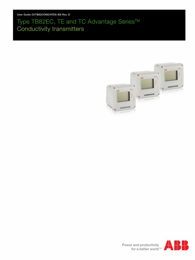
User Guide OI/TB82COND/ATEX–EN Rev. D
Type TB82EC, TE and TC Advantage SeriesTM
Conductivity transmitters

The CompanyWe are an established world force in the design and manufacture of measurement products for industrial process control, flow measurement, gas and liquid analysis and environmental applications.
As a part of ABB, a world leader in process automation technology, we offer customers application expertise, service and support worldwide.
We are committed to teamwork, high quality manufacturing, advanced technology and unrivalled service and support.
The quality, accuracy and performance of the Company’s products result from over 100 years experience, combined with a continuous program of innovative design and development to incorporate the latest technology.
TB82 Conductivity Series ATEX Product Instruction Manual ABB
2 TB82COND-ATEX-EN-B
CONTENTS Section Page CONTENTS.......................................................................2 USE OF INSTRUCTIONS .................................................2 INTRODUCTION...............................................................3 PRODUCT IDENTIFICATION ...........................................3 EUROPEAN ATEX DIRECTIVE INFORMATION..............3 EUROPEAN ATEX DIRECTIVE INFORMATION..............4 TRANSMITTER MOUNTING DETAILS...........................12 TRANSMITTER MOUNTING DETAILS...........................12 ELECTRICAL CONNECTIONS - Power..........................13 SENSOR CONNECTIONS – TB82EC/TE (2- and 4-
Electrode) ....................................................................14 SENSOR CONNECTIONS – TB82TC (Toroidal) ............15 OPERATING PROCEDURES .........................................16
Commissioning the Instrument ..................................16 Flow Chart for Basic Operation Mode: TB82EC Four-Electrode...........................................................17 Flow Chart for Basic Operation Mode: TB82TE Two-Electrode ...........................................................18 Flow Chart for Basic Operation Mode: TB82TC Toroidal......................................................................19
CONFIGURE MODE .......................................................20 TB82EC (Four-Electrode) Default Configuration .......20 TB82EC (Four-Electrode) Advanced Mode Flow Chart..........................................................................21 TB82TE (Two-Electrode) Default Configuration ........22 TB82TE (Two-Electrode) Advanced Mode Flow Chart..........................................................................23 TB82TC (Toroidal) Default Configuration ..................24 TB82TC (Toroidal) Advanced Mode Flow Chart ........25 Configuration Example – TB82EC Basic Configuration .............................................................26
CALIBRATION MODE.....................................................28 Calibration Flow Chart for TB82EC (Four Electrode) and TB82TE (Two Electrode) ...................28 Calibration Flow Chart for TB82TC (Toroidal Conductivity) ..............................................................28
OUTPUT/HOLD MODE...................................................29 SECURITY MODE ..........................................................29 SECONDARY DISPLAY MODE......................................29 MAINTENANCE ..............................................................29 DISMANTLING AND RE-ASSEMBLY.............................30 SPECIFICATIONS ..........................................................31
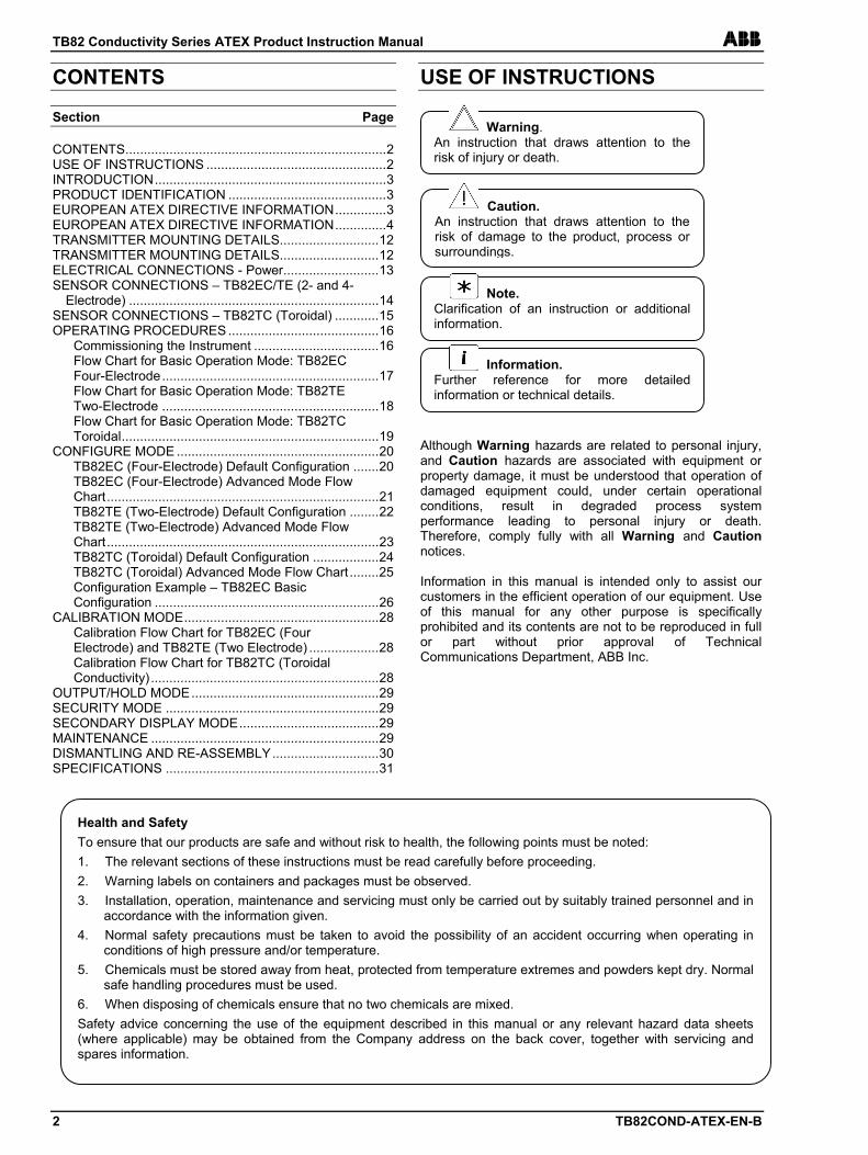
USE OF INSTRUCTIONS Although Warning hazards are related to personal injury, and Caution hazards are associated with equipment or property damage, it must be understood that operation of damaged equipment could, under certain operational conditions, result in degraded process system performance leading to personal injury or death. Therefore, comply fully with all Warning and Caution notices. Information in this manual is intended only to assist our customers in the efficient operation of our equipment. Use of this manual for any other purpose is specifically prohibited and its contents are not to be reproduced in full or part without prior approval of Technical Communications Department, ABB Inc.
Warning. An instruction that draws attention to the risk of injury or death.
Caution.An instruction that draws attention to the risk of damage to the product, process or surroundings.
Note.Clarification of an instruction or additional information.
Information.Further reference for more detailed information or technical details.
Health and Safety To ensure that our products are safe and without risk to health, the following points must be noted: 1. The relevant sections of these instructions must be read carefully before proceeding. 2. Warning labels on containers and packages must be observed. 3. Installation, operation, maintenance and servicing must only be carried out by suitably trained personnel and in
accordance with the information given. 4. Normal safety precautions must be taken to avoid the possibility of an accident occurring when operating in
conditions of high pressure and/or temperature. 5. Chemicals must be stored away from heat, protected from temperature extremes and powders kept dry. Normal
safe handling procedures must be used. 6. When disposing of chemicals ensure that no two chemicals are mixed. Safety advice concerning the use of the equipment described in this manual or any relevant hazard data sheets (where applicable) may be obtained from the Company address on the back cover, together with servicing and spares information.
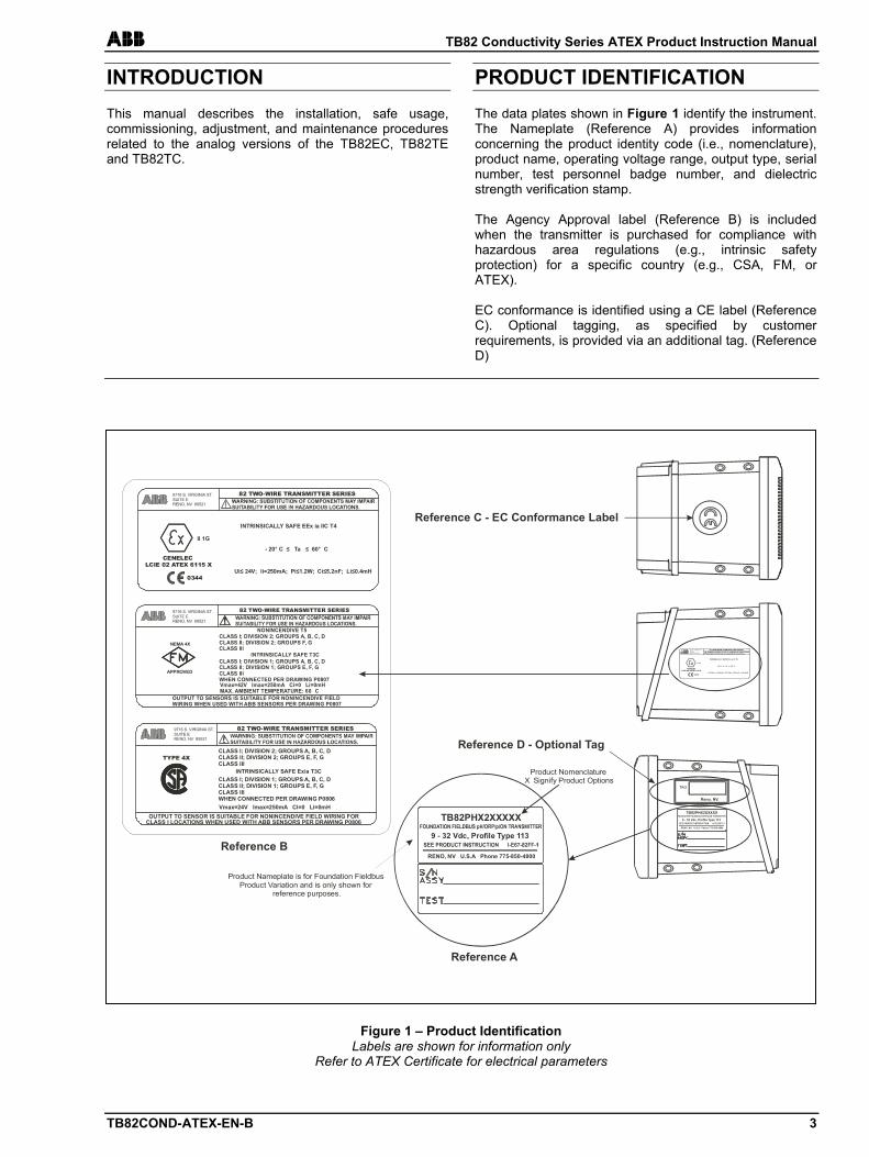
ABB TB82 Conductivity Series ATEX Product Instruction Manual
TB82COND-ATEX-EN-B 3
INTRODUCTION This manual describes the installation, safe usage, commissioning, adjustment, and maintenance procedures related to the analog versions of the TB82EC, TB82TE and TB82TC.
PRODUCT IDENTIFICATION The data plates shown in Figure 1 identify the instrument. The Nameplate (Reference A) provides information concerning the product identity code (i.e., nomenclature), product name, operating voltage range, output type, serial number, test personnel badge number, and dielectric strength verification stamp. The Agency Approval label (Reference B) is included when the transmitter is purchased for compliance with hazardous area regulations (e.g., intrinsic safety protection) for a specific country (e.g., CSA, FM, or ATEX). EC conformance is identified using a CE label (Reference C). Optional tagging, as specified by customer requirements, is provided via an additional tag. (Reference D)
Figure 1 – Product IdentificationLabels are shown for information only
Refer to ATEX Certificate for electrical parameters
OUTPUT TO SENSOR IS SUITABLE FOR NONINCENDIVE FIELD WIRING FORCLASS I LOCATIONS WHEN USED WITH ABB SENSORS PER DRAWING P0806
CLASS I; DIVISION 2; GROUPS A, B, C, DCLASS II; DIVISION 2; GROUPS E, F, GCLASS III
INTRINSICALLY SAFE Exia T3CCLASS I; DIVISION 1; GROUPS A, B, C, DCLASS II; DIVISION 1; GROUPS E, F, GCLASS IIIWHEN CONNECTED PER DRAWING P0806Vmax=24V Imax=250mA Ci=0 Li=0mH
82 TWO-WIRE TRANSMITTER SERIES
TYPE 4X
82 TWO-WIRE TRANSMITTER SERIES
NONINCENDIVE T5CLASS I; DIVISION 2; GROUPS A, B, C, DCLASS II; DIVISION 2; GROUPS F, GCLASS III
INTRINSICALLY SAFE T3CCLASS I; DIVISION 1; GROUPS A, B, C, DCLASS II; DIVISION 1; GROUPS E, F, GCLASS IIIWHEN CONNECTED PER DRAWING P0807Vmax=42V Imax=250mA Ci=0 Li=0mHMAX. AMBIENT TEMPERATURE: 60� C
OUTPUT TO SENSORS IS SUITABLE FOR NONINCENDIVE FIELDWIRING WHEN USED WITH ABB SENSORS PER DRAWING P0807
NEMA 4X
APPROVED
INTRINSICALLY SAFE EEx ia IIC T4
82 TWO-WIRE TRANSMITTER SERIES9716 S. VIRGINIA ST.SUITE ERENO, NV 89521
CENELECLCIE 02 ATEX 6115 X
Reference A
Reference D - Optional Tag
Reference B
Reference C - EC Conformance Label
TB82PHX2XXXXX
9 - 32 Vdc, Profile Type 113
RENO, NV U.S.A Phone 775-850-4800
Product Nomenclature�X� Signify Product Options
TAG
Reno, NV.
II 1G
0344
Product Nameplate is for Foundation FieldbusProduct Variation and is only shown for
reference purposes.
9716 S. VIRGINIA ST.SUITE ERENO, NV 89521
9716 S. VIRGINIA ST.SUITE ERENO, NV 89521
INTRINSICALLY SAFE EEx ia IIC T4
82 TWO-WIRE TRANSMITTER SERIES9716 S. VIRGINIA ST.SUITE ERENO, NV 89521
CENELECLCIE 02 ATEX 6115 X
II 1G
0344
TB82PHX2XXXXX
9 - 32 Vdc, Profile Type 113
RENO, NV U.S.A Phone 775-850-4800
TB82 Conductivity Series ATEX Product Instruction Manual ABB
4 TB82COND-ATEX-EN-B
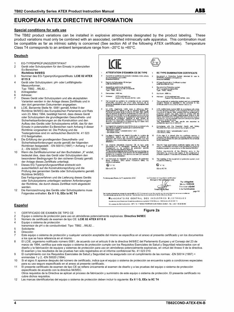
EUROPEAN ATEX DIRECTIVE INFORMATION Special conditions for safe use The TB82 product variations can be installed in explosive atmospheres designated by the product labeling. These product variations must only be combined with an associated, certified intrinsically safe apparatus. This combination must be compatible as far as intrinsic safety is concerned (See section A6 of the following ATEX certificate). Temperature Class T4 corresponds to an ambient temperature range from –20°C to +60°C. Deutsch 1 EG-TYPENPRÜFUNGSZERTIFIKAT 2 Gerät oder Schutzsystem für den Einsatz in potenziellen
Ex-Bereichen Richtlinie 94/9/EG
3 Nummer des EG-Typenprüfungszertifikats: LCIE 02 ATEX 6115 X
4 Gerät oder Schutzsystem: pH- oder Leitfähigkeits-Messumformer, Typ: TB82…/ML82…
5 Antragsteller: 6 Adresse: 7 Dieses Gerät oder Schutzsystem und alle akzeptablen
Varianten werden in der Anlage dieses Zertifikats und in den dort genannten Dokumenten angegeben.
8 LCIE, Benannte Stelle Nr. 0081 gemäß Artikel 9 der Richtlinie 94/9/EG des Europäischen Parlaments und Rats vom 23. März 1994, bestätigt hiermit, dass dieses Gerät oder Schutzsystem die grundlegenden Gesundheits- und Sicherheitsanforderungen an die Konstruktion und den Aufbau des Geräts oder Schutzsystems erfüllt, das für den Einsatz in potenziellen Ex-Bereichen nach Anhang II dieser Richtlinie vorgesehen ist. Die Prüfung und die Testergebnisse sind im vertraulichen Bericht Nr. 41 023 010 festgehalten.
9 Die Erfüllung der grundlegenden Gesundheits- und Sicherheitsanforderungen wurde gemäß der folgenden Richtlinien festgestellt: - EN 50014 (1997) + Anhang 1 und 2, - EN 50020 (1994)
10 Wenn die Zertifikatsnummer auf den Buchstaben „X“ endet, bedeutet dies, dass das Gerät oder Schutzsystem den besonderen Bedingungen für den sicheren Einsatz gemäß der Anlage dieses Zertifikats unterliegt.
11 Dieses EG-Typenprüfungszertifikat erstreckt sich ausschließlich auf die Konstruktionsprüfung und die Prüfung des genannten Geräts oder Schutzsystems gemäß Richtlinie 94/9/EG.
Das Fertigungsverfahren und die Lieferung dieses Geräts oder Schutzsystems unterliegen weiteren Anforderungen der Richtlinie, die durch dieses Zertifikat nicht abgedeckt werden.
12 Die Kennzeichnung des Geräts oder Schutzsystems muss Folgendes enthalten: Ex II 1 G, EEx ia IIC T4
Español 1 CERTIFICADO DE EXAMEN DE TIPO CE 2 Equipo o sistema de protección para uso en atmósferas potencialmente explosivas: Directiva 94/9EC 3 Número de certificado de examen de tipo CE: LCIE 02 ATEX 6115 X 4 Equipo o sistema de protección
transmisor de pH o de conductividad: Tipo: TB82…/ML82… 5 Solicitante: 6 Dirección: 7 Este equipo o sistema de protección y cualquier variación aceptable del mismo se especifica en el anexo al presente certificado y en los documentos
a los que se hace referencia en el mismo. 8 El LCIE, organismo notificado número 0081, de acuerdo con el artículo 9 de la directiva 94/9/EC del Parlamento Europeo y el Consejo del 23 de
marzo de 1994, certifica que este equipo o sistema de protección cumple con los Requisitos Esenciales de Salud y Seguridad relacionados con el diseño y la fabricación de equipos y sistemas de protección para uso en atmósferas potencialmente explosivas, en virtud del Anexo II de la directiva. El examen y los resultados de las pruebas han sido registrados en el informe confidencial No. 41 023 010.
9 El cumplimiento con los Requisitos Esenciales de Salud y Seguridad se ha asegurado con el cumplimiento de las normas: -EN 50014 (1997) + enmiendas 1 y 2, -EN 50020 (1994)
10 Si el signo X aparece después del número de certificado, indica que el equipo o sistema de protección se encuentra sujeto a condiciones especiales para su uso seguro especificado en el anexo al presente certificado.
11 El presente certificado de examen de tipo CE se refiere únicamente al examen de diseño y a las pruebas del equipo o sistema de protección especificado de acuerdo con la directiva 94/9/EC. Otros requisitos de la Directiva se aplican al proceso de fabricación y suministro de este equipo o sistema de protección. El presente certificado no cubre dichos requisitos.
12 Las marcas identificatorias del equipo o sistema de protección deben incluir lo siguiente: Ex II 1 G, EEx ia IIC T4
Figure 2a
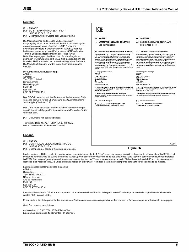
ABB TB82 Conductivity Series ATEX Product Instruction Manual
TB82COND-ATEX-EN-B 5
Deutsch (A1) ANLAGE (A2) EG-TYPENPRÜFUNGSZERTIFIKAT LCIE 02 ATEX 6115 X (A3) Beschreibung des Geräts oder Schutzsystems Die Messumformer TB82... oder ML82... liefern ein Ausgangssignal von 4 bis 20 mA als Reaktion auf die Ausgabe des angeschlossenen pH-Sensors (xx82PH) oder des Leitfähigkeitssensors mit vier Elektroden (xx82EC) oder des Leitfähigkeitssensors mit zwei Elektroden (xx82TE) oder des Toroidal-Leitfähigkeitssensors (xx82TC). Das HART-Datenübertragungsprotokoll kann dem 2-Leiter-Regelkreis überlagert werden. Die Modelle ML82 sind elektronisch mit den Modellen TB82 identisch; der Unterschied liegt in der Software. Die Modellausführungen werden in der Beschreibung näher erläutert. Die Kennzeichnung lautet wie folgt: ABB Inc. Adresse: … Typ: TB82…/ML82… Seriennummer Herstellungsjahr Ex II 1 G EEx ia IIC T4 LCIE 02 ATEX 6115 X Das CE-Zeichen muss mit der ID-Nummer der benannten Stelle versehen sein, die für die Überwachung des Qualitätssystems zuständig ist (0081 für LCIE). Das Gerät muss außerdem mit den üblichen Kennzeichnungen gemäß den einschlägigen Fertigungsstandards für solche Geräte versehen sein. (A4) Dokumente mit Beschreibungen: Technische Datei Nr. A27-TB82ATEX-ER02-002A. Diese Datei umfasst 43 Punkte (97 Seiten). Español (A1) ANEXO (A2) CERTIFICADO DE EXAMEN DE TIPO CE LCIE 02 ATEX 6115 X (A3) Descripción del equipo o sistema de protección Los transmisores TB82… o ML82… proporcionan una señal de salida de 4-20 mA como respuesta a la salida del sensor de pH conectado (xx82PH) o del sensor de conductividad de cuatro electrodos (xx82EC) o del sensor de conductividad de dos electrodos (xx82TE) o del sensor de conductividad toroidal (xx82TC).Pueden configurarse para el protocolo de comunicación HART superpuesto sobre el lazo de 2 hilos. Los modelos ML82 son electrónicamente idénticos a los modelos TB82, la única diferencia radica en el software. Remítase a las notas descriptivas para verificar el significado de modelo. Las marcas identificatorias son las siguientes: ABB Inc Dirección:… Tipo: TB82…/ML82… Número de serie Año de fabricación Ex II 1 G EEx ia IIC T4 LCIE 02 ATEX 6115 X La marca identificatoria CE estará acompañada por el número de identificación del organismo notificado responsable de la supervisión del sistema de calidad (0081 para el LCIE). El equipo también debe presentar las marcas identificatorias convencionales requeridas por las normas de fabricación que se aplican a dichos equipos. (A4) Documentos descriptivos: Archivo técnico n° A27-TB82ATEX-ER02-002A. Este archivo comprende 43 elementos (97 páginas).
Figure 2b
TB82 Conductivity Series ATEX Product Instruction Manual ABB
6 TB82COND-ATEX-EN-B
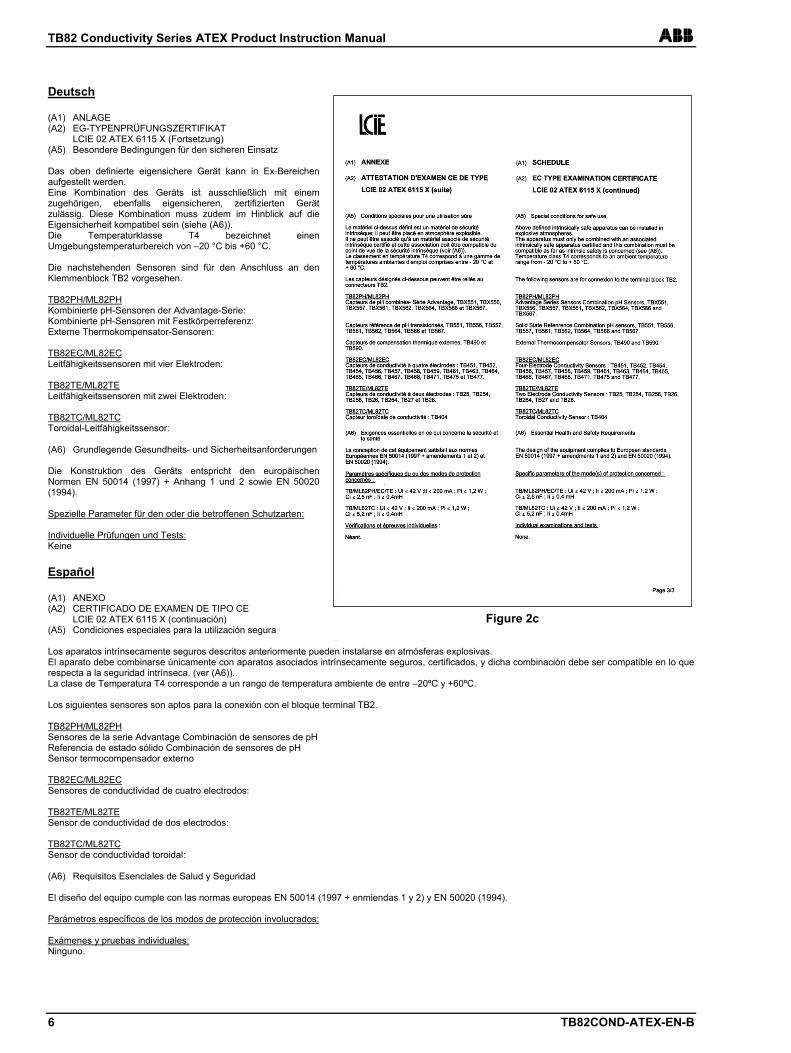
Deutsch (A1) ANLAGE (A2) EG-TYPENPRÜFUNGSZERTIFIKAT LCIE 02 ATEX 6115 X (Fortsetzung) (A5) Besondere Bedingungen für den sicheren Einsatz Das oben definierte eigensichere Gerät kann in Ex-Bereichen aufgestellt werden. Eine Kombination des Geräts ist ausschließlich mit einem zugehörigen, ebenfalls eigensicheren, zertifizierten Gerät zulässig. Diese Kombination muss zudem im Hinblick auf die Eigensicherheit kompatibel sein (siehe (A6)). Die Temperaturklasse T4 bezeichnet einen Umgebungstemperaturbereich von –20 °C bis +60 °C. Die nachstehenden Sensoren sind für den Anschluss an den Klemmenblock TB2 vorgesehen. TB82PH/ML82PH Kombinierte pH-Sensoren der Advantage-Serie: Kombinierte pH-Sensoren mit Festkörperreferenz: Externe Thermokompensator-Sensoren: TB82EC/ML82EC Leitfähigkeitssensoren mit vier Elektroden: TB82TE/ML82TE Leitfähigkeitssensoren mit zwei Elektroden: TB82TC/ML82TC Toroidal-Leitfähigkeitssensor: (A6) Grundlegende Gesundheits- und Sicherheitsanforderungen Die Konstruktion des Geräts entspricht den europäischen Normen EN 50014 (1997) + Anhang 1 und 2 sowie EN 50020 (1994). Spezielle Parameter für den oder die betroffenen Schutzarten: Individuelle Prüfungen und Tests: Keine Español (A1) ANEXO (A2) CERTIFICADO DE EXAMEN DE TIPO CE LCIE 02 ATEX 6115 X (continuación) (A5) Condiciones especiales para la utilización segura Los aparatos intrínsecamente seguros descritos anteriormente pueden instalarse en atmósferas explosivas. El aparato debe combinarse únicamente con aparatos asociados intrínsecamente seguros, certificados, y dicha combinación debe ser compatible en lo que respecta a la seguridad intrínseca. (ver (A6)). La clase de Temperatura T4 corresponde a un rango de temperatura ambiente de entre –20ºC y +60ºC. Los siguientes sensores son aptos para la conexión con el bloque terminal TB2. TB82PH/ML82PH Sensores de la serie Advantage Combinación de sensores de pH Referencia de estado sólido Combinación de sensores de pH Sensor termocompensador externo TB82EC/ML82EC Sensores de conductividad de cuatro electrodos: TB82TE/ML82TE Sensor de conductividad de dos electrodos: TB82TC/ML82TC Sensor de conductividad toroidal: (A6) Requisitos Esenciales de Salud y Seguridad El diseño del equipo cumple con las normas europeas EN 50014 (1997 + enmiendas 1 y 2) y EN 50020 (1994). Parámetros específicos de los modos de protección involucrados: Exámenes y pruebas individuales: Ninguno.
Figure 2c
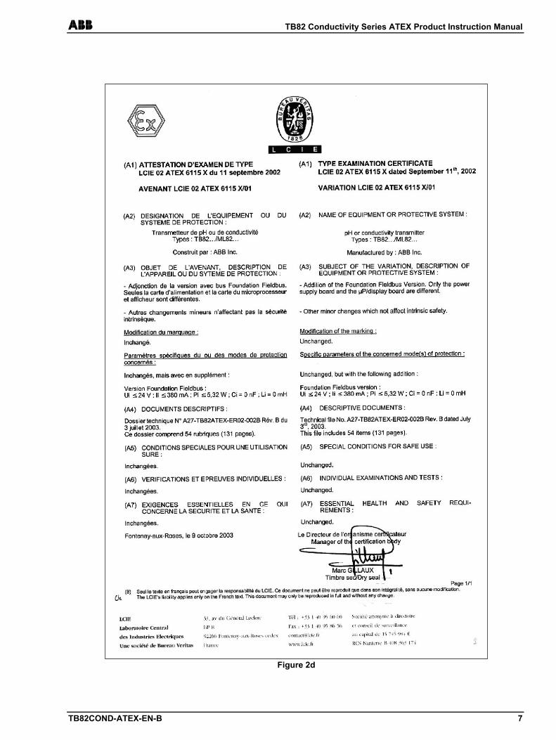
ABB TB82 Conductivity Series ATEX Product Instruction Manual
TB82COND-ATEX-EN-B 7
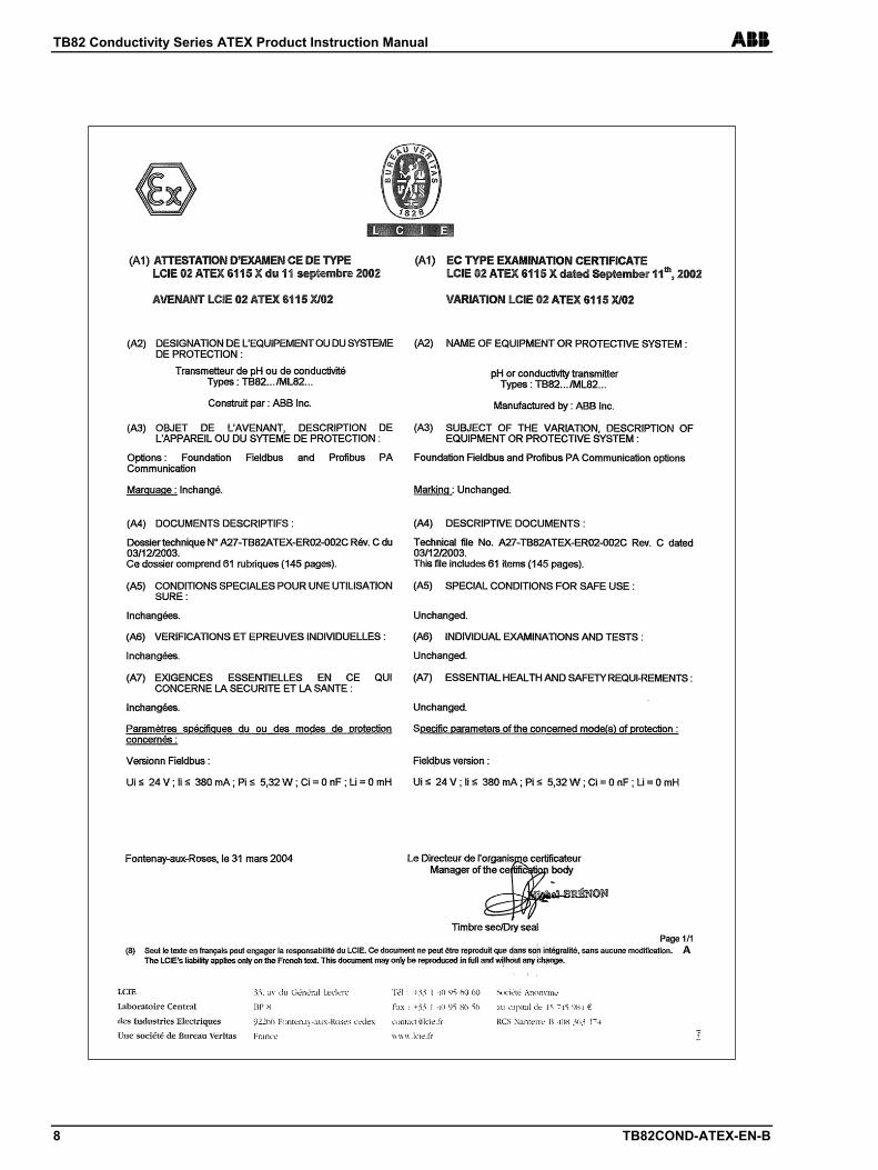
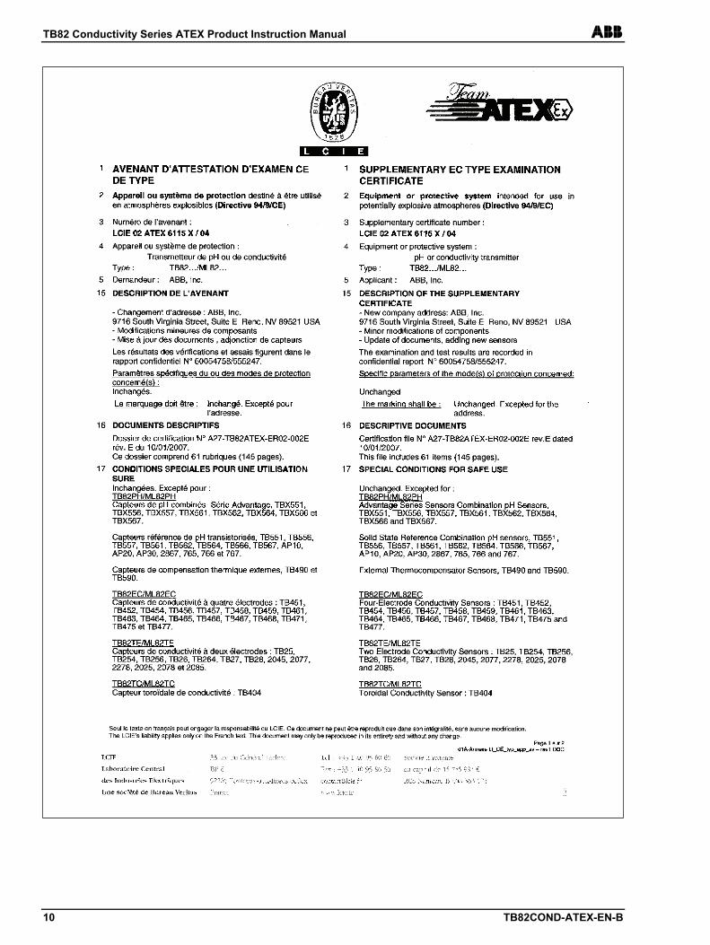
Figure 2d
TB82 Conductivity Series ATEX Product Instruction Manual ABB
8 TB82COND-ATEX-EN-B
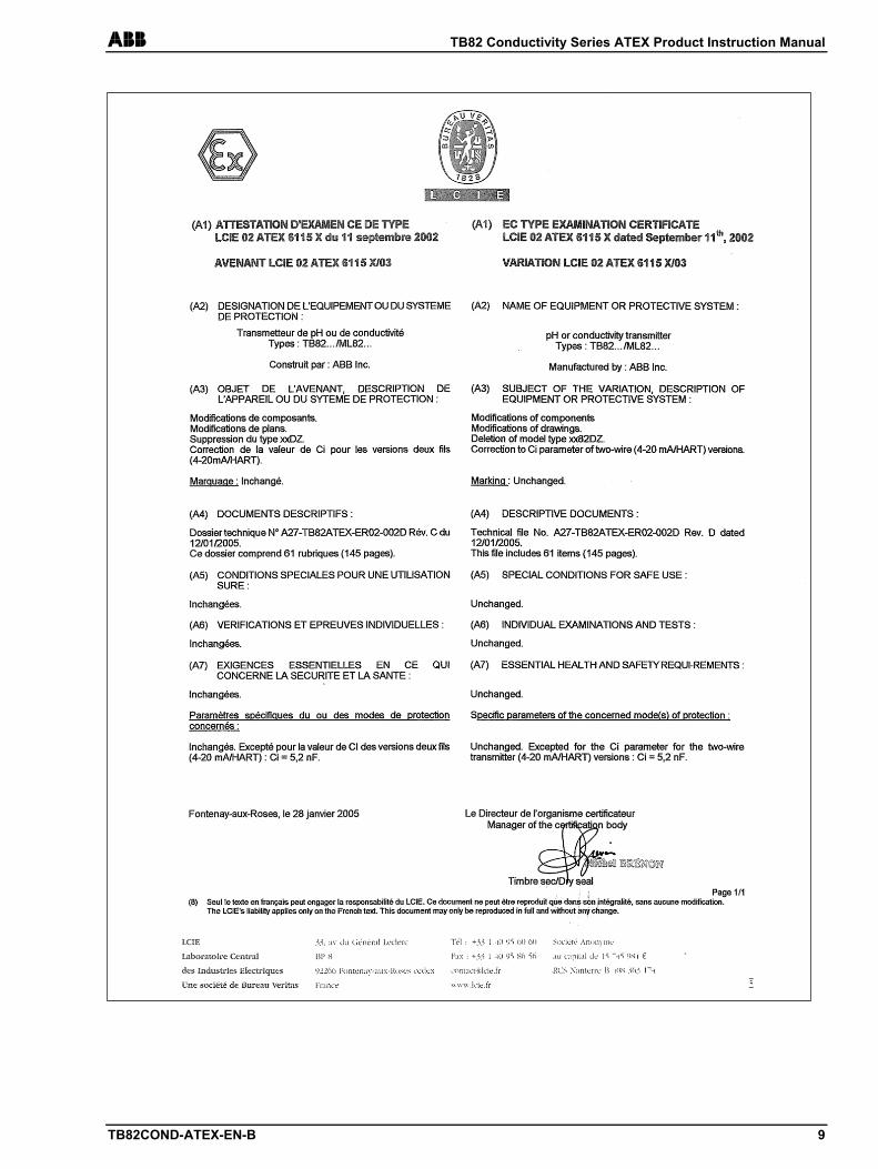
ABB TB82 Conductivity Series ATEX Product Instruction Manual
TB82COND-ATEX-EN-B 9
TB82 Conductivity Series ATEX Product Instruction Manual ABB
10 TB82COND-ATEX-EN-B
ABB TB82 Conductivity Series ATEX Product Instruction Manual
TB82COND-ATEX-EN-B 11
TB82 Conductivity Series ATEX Product Instruction Manual ABB
12 TB82COND-ATEX-EN-B
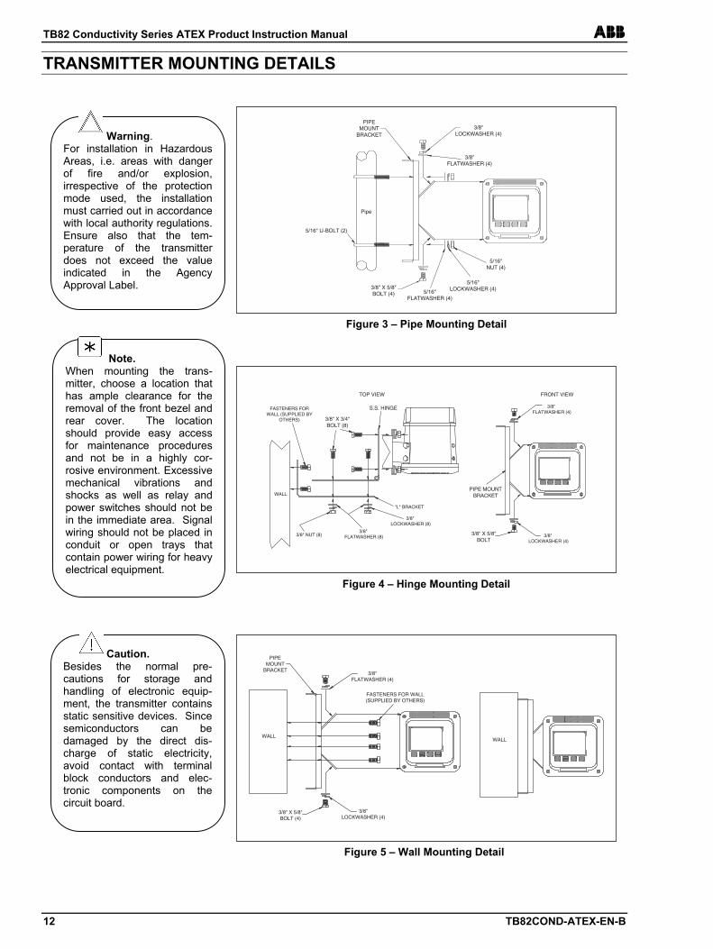
TRANSMITTER MOUNTING DETAILS
Warning. For installation in Hazardous Areas, i.e. areas with danger of fire and/or explosion, irrespective of the protection mode used, the installation must carried out in accordance with local authority regulations. Ensure also that the tem-perature of the transmitter does not exceed the value indicated in the Agency Approval Label.
Caution. Besides the normal pre-cautions for storage and handling of electronic equip-ment, the transmitter contains static sensitive devices. Since semiconductors can be damaged by the direct dis-charge of static electricity, avoid contact with terminal block conductors and elec-tronic components on the circuit board.
Note. When mounting the trans-mitter, choose a location that has ample clearance for the removal of the front bezel and rear cover. The location should provide easy access for maintenance procedures and not be in a highly cor-rosive environment. Excessive mechanical vibrations and shocks as well as relay and power switches should not be in the immediate area. Signal wiring should not be placed in conduit or open trays that contain power wiring for heavy electrical equipment.
5/16" U-BOLT (2)
PIPEMOUNT
BRACKET3/8"
LOCKWASHER (4)
3/8"FLATWASHER (4)
3/8" X 5/8"BOLT (4) 5/16"
FLATWASHER (4)
5/16"LOCKWASHER (4)
5/16"NUT (4)
Pipe
Figure 3 – Pipe Mounting Detail
Figure 4 – Hinge Mounting Detail
WALL
FASTENERS FORWALL (SUPPLIED BY
OTHERS)
3/8" NUT (8)3/8"
FLATWASHER (8)
3/8" FLATWASHER (4)
3/8" LOCKWASHER (8)
3/8" LOCKWASHER (4)
"L" BRACKET
FRONT VIEWTOP VIEW
3/8" X 3/4"BOLT (8)
S.S. HINGE
PIPE MOUNTBRACKET
3/8" X 5/8"BOLT
Figure 5 – Wall Mounting Detail
WALL
PIPEMOUNT
BRACKET3/8"
FLATWASHER (4)
3/8" X 5/8"BOLT (4)
3/8"LOCKWASHER (4)
FASTENERS FOR WALL(SUPPLIED BY OTHERS)
WALL
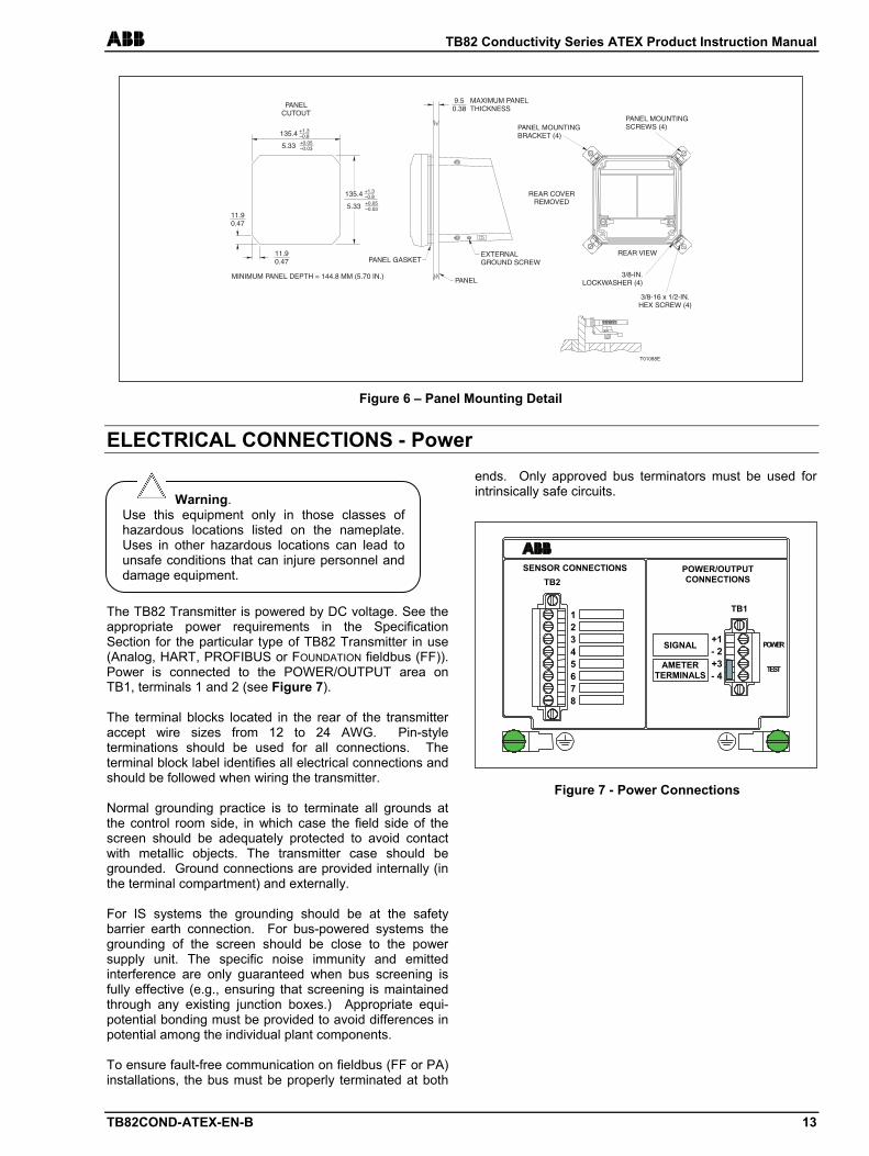
ABB TB82 Conductivity Series ATEX Product Instruction Manual
TB82COND-ATEX-EN-B 13
ELECTRICAL CONNECTIONS - Power
The TB82 Transmitter is powered by DC voltage. See the appropriate power requirements in the Specification Section for the particular type of TB82 Transmitter in use (Analog, HART, PROFIBUS or FOUNDATION fieldbus (FF)). Power is connected to the POWER/OUTPUT area on TB1, terminals 1 and 2 (see Figure 7). The terminal blocks located in the rear of the transmitter accept wire sizes from 12 to 24 AWG. Pin-style terminations should be used for all connections. The terminal block label identifies all electrical connections and should be followed when wiring the transmitter. Normal grounding practice is to terminate all grounds at the control room side, in which case the field side of the screen should be adequately protected to avoid contact with metallic objects. The transmitter case should be grounded. Ground connections are provided internally (in the terminal compartment) and externally. For IS systems the grounding should be at the safety barrier earth connection. For bus-powered systems the grounding of the screen should be close to the power supply unit. The specific noise immunity and emitted interference are only guaranteed when bus screening is fully effective (e.g., ensuring that screening is maintained through any existing junction boxes.) Appropriate equi-potential bonding must be provided to avoid differences in potential among the individual plant components. To ensure fault-free communication on fieldbus (FF or PA) installations, the bus must be properly terminated at both
ends. Only approved bus terminators must be used for intrinsically safe circuits.
REAR COVERREMOVED
EXTERNALGROUND SCREW
T01088E
PANEL GASKET
PANEL
9.50.38
MAXIMUM PANELTHICKNESS
EPTHNEL D
PANELCUTOUT
MINIMUM PA = 144.8 MM (5.70 IN.)
11.90.47
135.4 +1.3–0.8
5.33 +0.05–0.03
135.4 +1.3–0.8
5.33 +0.05–0.03
11.90.47
LOCK ASHER (4)
REAR VIEW
PANEL MOUNTINGBRACKET (4)
3/8-IN.W
3/8-16 x 1/2-IN.HEX SCREW (4)
PANEL MOUNTINGSCREWS (4)
Figure 6 – Panel Mounting Detail
Warning. Use this equipment only in those classes of hazardous locations listed on the nameplate. Uses in other hazardous locations can lead to unsafe conditions that can injure personnel and damage equipment.
Figure 7 - Power Connections
SENSOR CONNECTIONS TB2
POWER/OUTPUTCONNECTIONS
POWER
TEST
12345678
+1- 2+3- 4
SIGNAL
AMETERTERMINALS
TB1
TB82 Conductivity Series ATEX Product Instruction Manual ABB
14 TB82COND-ATEX-EN-B
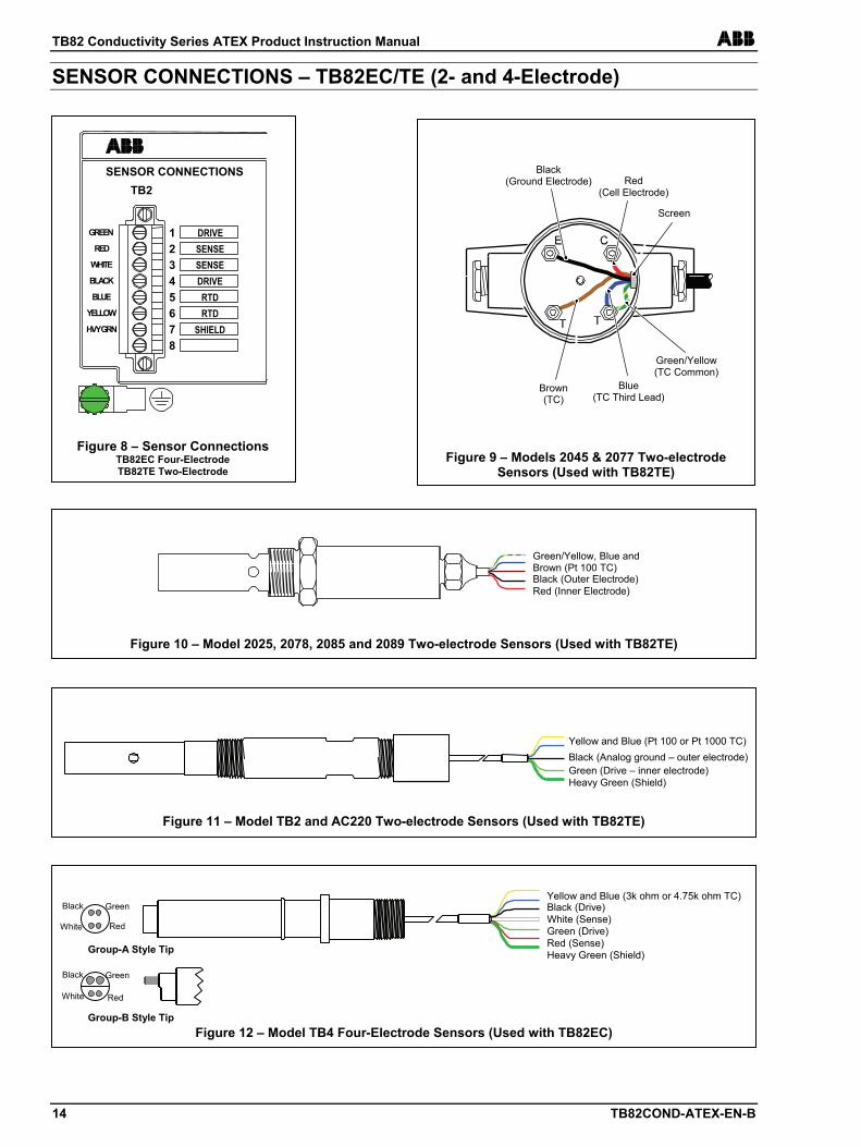
SENSOR CONNECTIONS – TB82EC/TE (2- and 4-Electrode)
SENSOR CONNECTIONS TB2
GREEN
RED
WHITE
BLACK
BLUE
YELLOW
HVY GRN
DRIVE SENSE SENSE DRIVE RTD RTD
SHIELD
1 2 3 4 5 6 7 8
Figure 8 – Sensor Connections TB82EC Four-Electrode TB82TE Two-Electrode
Figure 10 – Model 2025, 2078, 2085 and 2089 Two-electrode Sensors (Used with TB82TE)
Green/Yellow, Blue and Brown (Pt 100 TC)
Red (Inner Electrode) Black (Outer Electrode)
Figure 11 – Model TB2 and AC220 Two-electrode Sensors (Used with TB82TE)
Yellow and Blue (Pt 100 or Pt 1000 TC)
Green (Drive – inner electrode) Black (Analog ground – outer electrode)
Heavy Green (Shield)
Figure 12 – Model TB4 Four-Electrode Sensors (Used with TB82EC)
Yellow and Blue (3k ohm or 4.75k ohm TC)
Green (Drive)
Black (Drive)
Red (Sense)
White (Sense)
Heavy Green (Shield) Group-A Style Tip
Group-B Style Tip
White Red
Black Green
Red White
Black Green
Figure 9 – Models 2045 & 2077 Two-electrode Sensors (Used with TB82TE)
Screen
Green/Yellow (TC Common)
Brown (TC)
Black (Ground Electrode) Red
(Cell Electrode)
Blue (TC Third Lead)
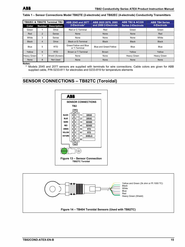
ABB TB82 Conductivity Series ATEX Product Instruction Manual
TB82COND-ATEX-EN-B 15
Table 1 – Sensor Connections Model TB82TE (2-electrode) and TB82EC (4-electrode) Conductivity Transmitters
TB82EC & TB82TE Terminal TB2 Color Number Description
ABB 2045 and 2077 2-Electrode*
ABB 2025 2078, 2085 and 2089 2-Electrode
ABB TB2 & AC220 Series 2-Electrode
ABB TB4 Series 4-Electrode
Green 1 Drive Red or C-Terminal Red Green Green
Red 2 Sense None None None Red
White 3 Sense None None None White
Black 4 Drive Black or E-Terminal Black Black Black
Blue 5 RTD Green/Yellow and Blue or T-Terminal Blue and Green/Yellow Blue Blue
Yellow 6 RTD Brown or T-Terminal Brown Yellow Yellow
Heavy Green 7 Shield (Screen) None None Heavy Green Heavy Green
None 8 Not Used None None None None
Notes: * Models 2045 and 2077 sensors are supplied with terminals for wire connections. Cable colors are given for ABB
supplied cable, P/N 0233-811 for electrodes and 0233-819 for temperature elements
SENSOR CONNECTIONS – TB82TC (Toroidal)
SENSOR CONNECTIONS TB2
BLACK
BLUE
WHITE
RED
GREEN
YELLOW
HVY GRN
DRIVE DRIVE SENSE SENSE
RTD RTD
SHIELD
12345678
Figure 13 – Sensor ConnectionTB82TC Toroidal
Yellow and Green (3k ohm or Pt 1000 TC)
Blue
Black
Red
White
Heavy Green (Shield)
Figure 14 – TB404 Toroidal Sensors (Used with TB82TC)
TB82 Conductivity Series ATEX Product Instruction Manual ABB
16 TB82COND-ATEX-EN-B
Figure 15
MEASURE CALIBRATE OUT/HOLD CONFIGURE SECURITY DISPLAY
300 25°C
exit to MEASURE FAULT info
SELECT ENTER
YES NEXT
NO MENU
%
mS/cm μS/cm
Mohms-cm ppm ppb S/m
mS/m
OUTPUTHELD
SPIKE FAULT
M
ABB TB82Hidden Key
(User Mode)
MEASURE CALIBRATE OUT/HOLD CONFIGURE SECURITY DISPLAY
300 25°C
MENU
μS/cm
M
Figure 16
MEASURE CALIBRATE OUT/HOLD CONFIGURE SECURITY DISPLAY
300 Calibr
exit to MEASURE
SELECT
MENU
μS/cm
Figure 17
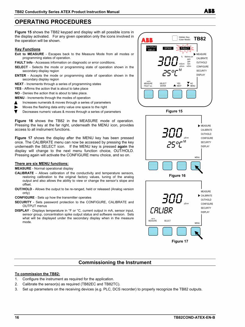
OPERATING PROCEDURES Figure 15 shows the TB82 keypad and display with all possible icons in the display activated. For any given operation only the icons involved in the operation will be shown. Key Functions Exit to MEASURE - Escapes back to the Measure Mode from all modes or
programming states of operation. FAULT Info - Accesses information on diagnostic or error conditions. SELECT - Selects the mode or programming state of operation shown in the
secondary display region ENTER - Accepts the mode or programming state of operation shown in the
secondary display region NEXT - Increments through a series of programming states YES - Affirms the action that is about to take place NO - Denies the action that is about to take place. MENU - Increments through the modes of operation Increases numerals & moves through a series of parameters Moves the flashing data entry value one space to the right Decreases numeric values & moves through a series of parameters Figure 16 shows the TB82 in the MEASURE mode of operation. Pressing the key at the far right, underneath the MENU icon, provides access to all instrument functions. Figure 17 shows the display after the MENU key has been pressed once. The CALIBRATE menu can now be accessed by pressing the key underneath the SELECT icon. If the MENU key is pressed again the display will change to the next menu function choice, OUT/HOLD. Pressing again will activate the CONFIGURE menu choice, and so on. There are six MENU functions: MEASURE - Normal operational display CALIBRATE – Allows calibration of the conductivity and temperature sensors,
restoring calibration to the original factory values, tuning of the analog output and also allows the ability to view or change the sensor’s slope and offset.
OUT/HOLD - Allows the output to be re-ranged, held or released (Analog version only)
CONFIGURE - Sets up how the transmitter operates SECURITY - Sets password protection to the CONFIGURE, CALIBRATE and
OUTPUT menus DISPLAY - Displays temperature in °F or °C, current output in mA, sensor input,
sensor group, concentration spike output status and software revision. Sets what will be displayed under the secondary display when in the measure mode.
Commissioning the Instrument To commission the TB82: 1. Configure the instrument as required for the application. 2. Calibrate the sensor(s) as required (TB82EC and TB82TC). 3. Set up parameters on the receiving devices (e.g. PLC, DCS recorder) to properly recognize the TB82 outputs.
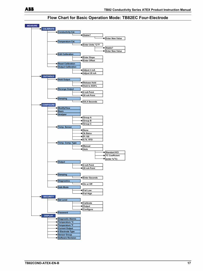
ABB TB82 Conductivity Series ATEX Product Instruction Manual
TB82COND-ATEX-EN-B 17
Flow Chart for Basic Operation Mode: TB82EC Four-Electrode
MEASURECALIBRATE
Conductivity Cal.Stable?
Enter New ValueTemperature Cal.
Enter Units °C/°F Stable?Enter New Value
Edit CalibrationEnter SlopeEnter Offset
Reset CalibrationOutput Calibration
Adjust 4 mAAdjust 20 mA
OUT/HOLDHold Output
Release HoldHold to XXX%
Rerange Output4 mA Point20 mA Point
DampingXX.X Seconds
CONFIGUREModify/ViewBasicAnalyzer
Group AGroup BGroup C
Temp. SensorNone3k BalcoPt 1004.7k. RTD
Temp. Comp. TypeManualAuto
Standard KClTC Coefficient(enter %/oC)
Output4 mA Point20 mA Point
DampingEnter Seconds
DiagnosticsOn or Off
Safe ModeFail LowFail High
SECURITYSet Level
CalibrateOutputConfigure
PasswordDISPLAY
Diagnostic Alarms Temperature °CTemperature °FCurrent Output4 Electrode TypeSensor GroupSoftware Revision
TB82 Conductivity Series ATEX Product Instruction Manual ABB
18 TB82COND-ATEX-EN-B
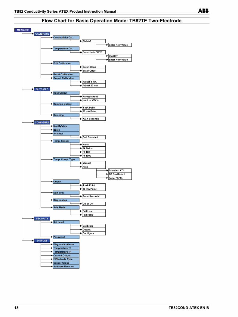
Flow Chart for Basic Operation Mode: TB82TE Two-Electrode MEASURE
CALIBRATEConductivity Cal.
Stable?Enter New Value
Temperature Cal.Enter Units °C/°F
Stable?Enter New Value
Edit CalibrationEnter SlopeEnter Offset
Reset CalibrationOutput Calibration
Adjust 4 mAAdjust 20 mA
OUT/HOLDHold Output
Release HoldHold to XXX%
Rerange Output4 mA Point20 mA Point
DampingXX.X Seconds
CONFIGUREModify/ViewBasicAnalyzer
Cell ConstantTemp. Sensor
None3k BalcoPt 100Pt 1000
Temp. Comp. TypeManualAuto
Standard KClTC Coefficient(enter %/oC)
Output4 mA Point20 mA Point
DampingEnter Seconds
DiagnosticsOn or Off
Safe ModeFail LowFail High
SECURITYSet Level
CalibrateOutputConfigure
PasswordDISPLAY
Diagnostic Alarms Temperature °CTemperature °FCurrent Output2 Electrode TypeSensor GroupSoftware Revision
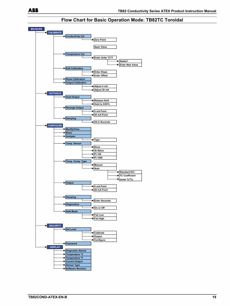
ABB TB82 Conductivity Series ATEX Product Instruction Manual
TB82COND-ATEX-EN-B 19
Flow Chart for Basic Operation Mode: TB82TC Toroidal
MEASURECALIBRATE
Conductivity Cal.Zero Point
Span Value
Temperature Cal.Enter Units °C/°F
Stable?Enter New Value
Edit CalibrationEnter SlopeEnter Offset
Reset CalibrationOutput Calibration
Adjust 4 mAAdjust 20 mA
OUT/HOLDHold Output
Release HoldHold to XXX%
Rerange Output4 mA Point20 mA Point
DampingXX.X Seconds
CONFIGUREModify/ViewBasicAnalyzer
TypeTemp. Sensor
None3k BalcoPt 100Pt 1000
Temp. Comp. TypeManualAuto
Standard KClTC Coefficient(enter %/oC)
Output4 mA Point20 mA Point
DampingEnter Seconds
DiagnosticsOn or Off
Safe ModeFail LowFail High
SECURITYSet Level
CalibrateOutputConfigure
PasswordDISPLAY
Diagnostic Alarms Temperature °CTemperature °FCurrent OutputSensor TypeSoftware Revision
TB82 Conductivity Series ATEX Product Instruction Manual ABB
20 TB82COND-ATEX-EN-B
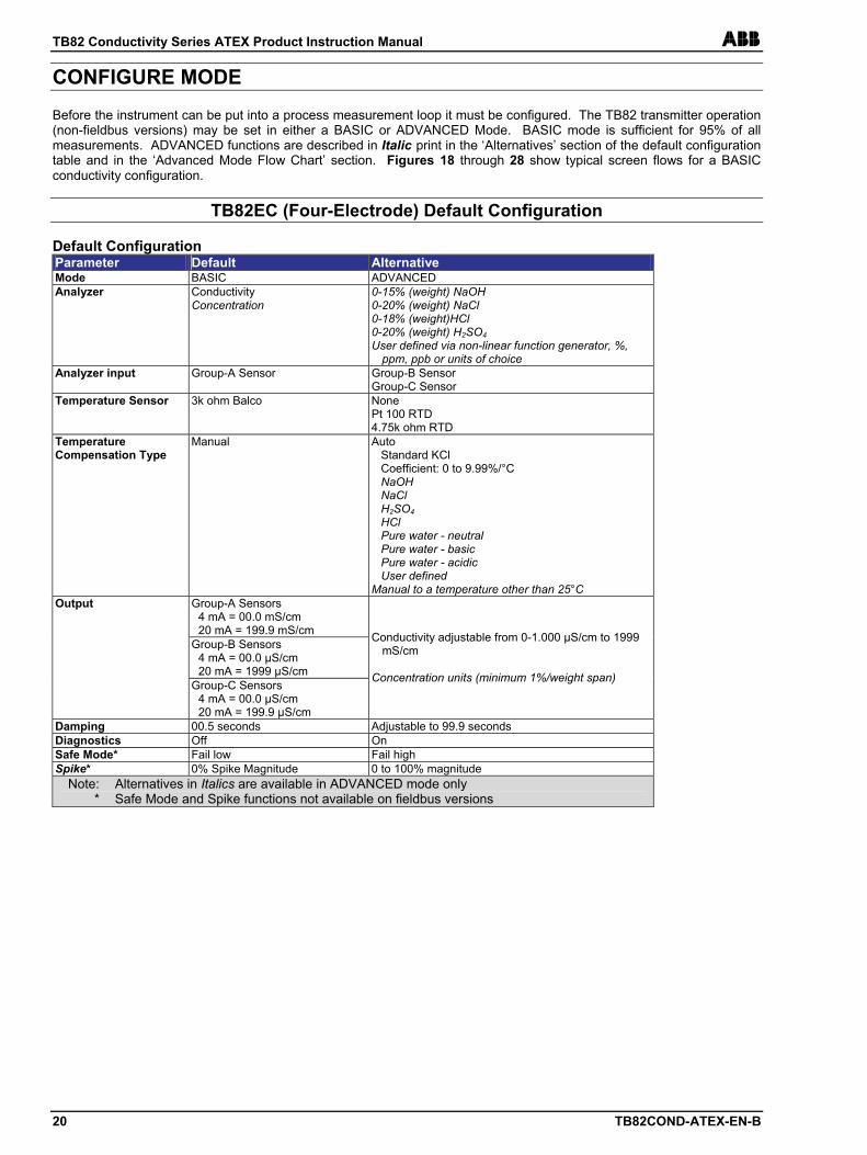
CONFIGURE MODE Before the instrument can be put into a process measurement loop it must be configured. The TB82 transmitter operation (non-fieldbus versions) may be set in either a BASIC or ADVANCED Mode. BASIC mode is sufficient for 95% of all measurements. ADVANCED functions are described in Italic print in the ‘Alternatives’ section of the default configuration table and in the ‘Advanced Mode Flow Chart’ section. Figures 18 through 28 show typical screen flows for a BASIC conductivity configuration.
TB82EC (Four-Electrode) Default Configuration Default Configuration Parameter Default Alternative Mode BASIC ADVANCED Analyzer Conductivity
Concentration 0-15% (weight) NaOH 0-20% (weight) NaCl 0-18% (weight)HCl 0-20% (weight) H2SO4 User defined via non-linear function generator, %,
ppm, ppb or units of choice Analyzer input Group-A Sensor Group-B Sensor
Group-C Sensor Temperature Sensor 3k ohm Balco None
Pt 100 RTD 4.75k ohm RTD
Temperature Compensation Type
Manual Auto Standard KCl Coefficient: 0 to 9.99%/°C NaOH NaCl H2SO4 HCl Pure water - neutral Pure water - basic Pure water - acidic User defined Manual to a temperature other than 25°C
Group-A Sensors 4 mA = 00.0 mS/cm 20 mA = 199.9 mS/cm
Group-B Sensors 4 mA = 00.0 µS/cm 20 mA = 1999 µS/cm
Output
Group-C Sensors 4 mA = 00.0 µS/cm 20 mA = 199.9 µS/cm
Conductivity adjustable from 0-1.000 µS/cm to 1999 mS/cm
Concentration units (minimum 1%/weight span)
Damping 00.5 seconds Adjustable to 99.9 seconds Diagnostics Off On Safe Mode* Fail low Fail high Spike* 0% Spike Magnitude 0 to 100% magnitude
Note: Alternatives in Italics are available in ADVANCED mode only * Safe Mode and Spike functions not available on fieldbus versions
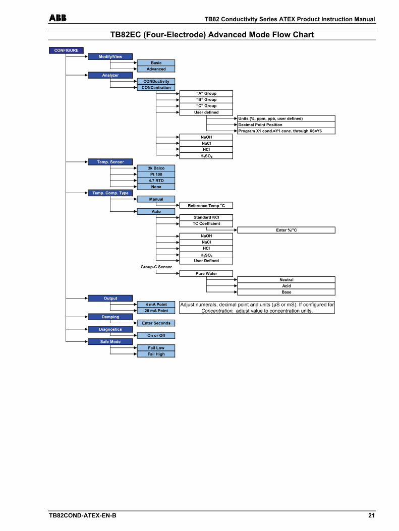
ABB TB82 Conductivity Series ATEX Product Instruction Manual
TB82COND-ATEX-EN-B 21
TB82EC (Four-Electrode) Advanced Mode Flow Chart
CONFIGUREModify/View
BasicAdvanced
AnalyzerCONDuctivity
CONCentration“A” Group“B” Group“C” Group
User definedUnits (%, ppm, ppb, user defined)Decimal Point PositionProgram X1 cond.=Y1 conc. through X6=Y6
NaOHNaClHCl
H2SO4
Temp. Sensor3k Balco
Pt 1004.7 RTD
NoneTemp. Comp. Type
ManualReference Temp oC
AutoStandard KClTC Coefficient
Enter %/°CNaOHNaClHCl
H2SO4
User DefinedGroup-C Sensor
Pure WaterNeutral
AcidBase
Output4 mA Point20 mA Point
DampingEnter Seconds
DiagnosticsOn or Off
Safe ModeFail LowFail High
Adjust numerals, decimal point and units (µS or mS). If configured for Concentration, adjust value to concentration units.
TB82 Conductivity Series ATEX Product Instruction Manual ABB
22 TB82COND-ATEX-EN-B
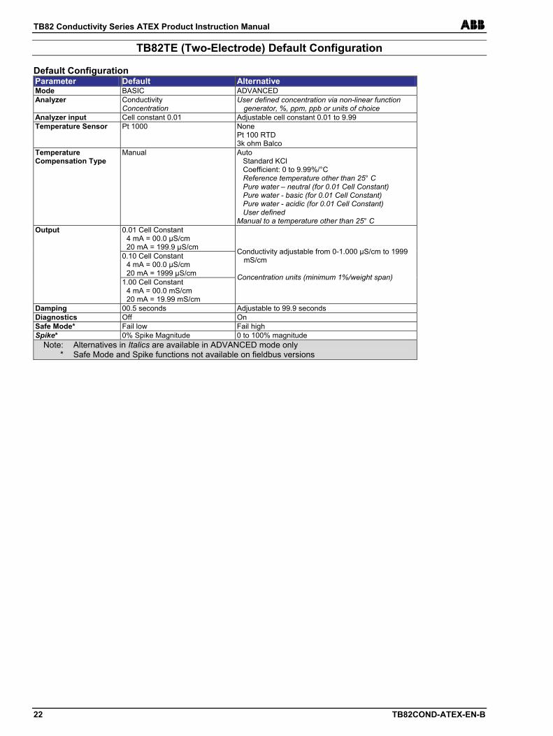
TB82TE (Two-Electrode) Default Configuration Default Configuration Parameter Default Alternative Mode BASIC ADVANCED Analyzer Conductivity
Concentration User defined concentration via non-linear function
generator, %, ppm, ppb or units of choice Analyzer input Cell constant 0.01 Adjustable cell constant 0.01 to 9.99 Temperature Sensor Pt 1000 None
Pt 100 RTD 3k ohm Balco
Temperature Compensation Type
Manual Auto Standard KCl Coefficient: 0 to 9.99%/°C Reference temperature other than 25° C Pure water – neutral (for 0.01 Cell Constant) Pure water - basic (for 0.01 Cell Constant) Pure water - acidic (for 0.01 Cell Constant) User defined Manual to a temperature other than 25° C
0.01 Cell Constant 4 mA = 00.0 µS/cm 20 mA = 199.9 µS/cm
0.10 Cell Constant 4 mA = 00.0 µS/cm 20 mA = 1999 µS/cm
Output
1.00 Cell Constant 4 mA = 00.0 mS/cm 20 mA = 19.99 mS/cm
Conductivity adjustable from 0-1.000 µS/cm to 1999 mS/cm
Concentration units (minimum 1%/weight span)
Damping 00.5 seconds Adjustable to 99.9 seconds Diagnostics Off On Safe Mode* Fail low Fail high Spike* 0% Spike Magnitude 0 to 100% magnitude
Note: Alternatives in Italics are available in ADVANCED mode only * Safe Mode and Spike functions not available on fieldbus versions
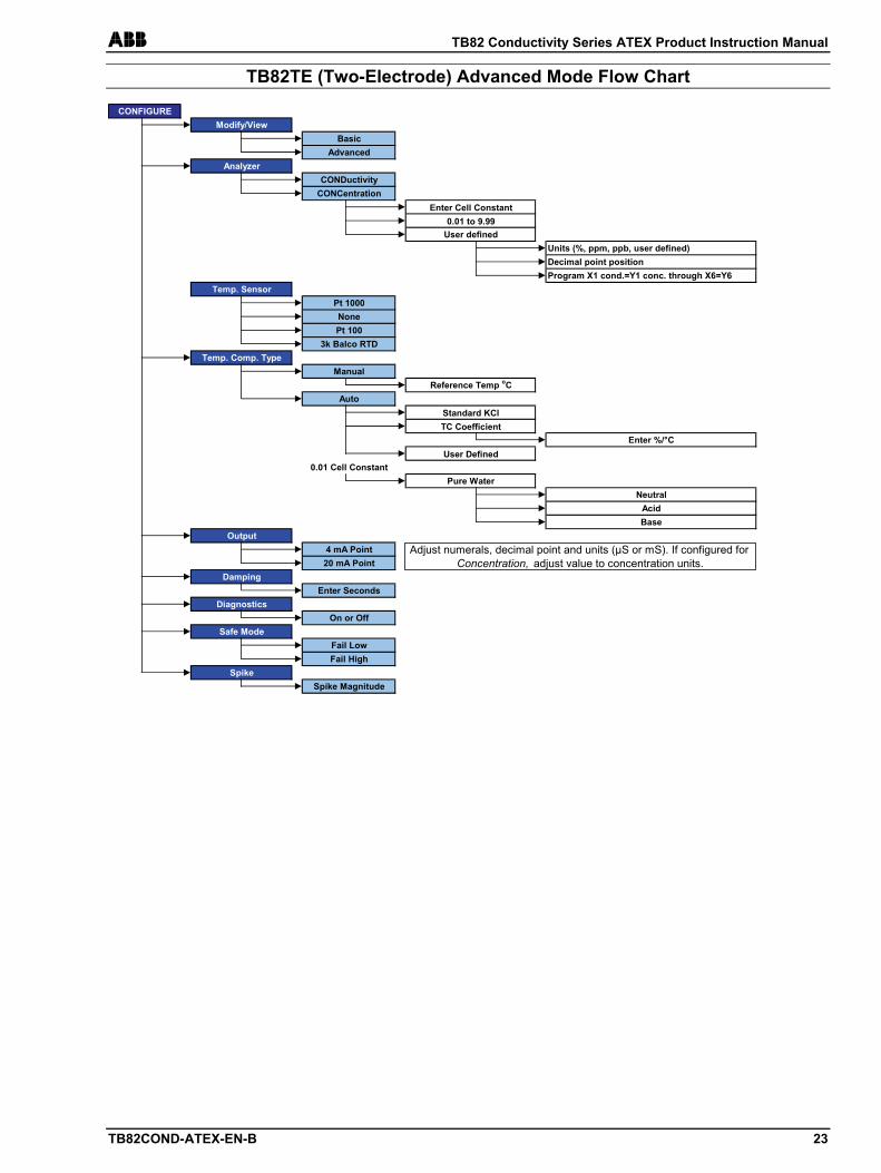
ABB TB82 Conductivity Series ATEX Product Instruction Manual
TB82COND-ATEX-EN-B 23
TB82TE (Two-Electrode) Advanced Mode Flow Chart
CONFIGUREModify/View
BasicAdvanced
AnalyzerCONDuctivity
CONCentrationEnter Cell Constant
0.01 to 9.99User defined
Units (%, ppm, ppb, user defined)Decimal point positionProgram X1 cond.=Y1 conc. through X6=Y6
Temp. SensorPt 1000NonePt 100
3k Balco RTDTemp. Comp. Type
ManualReference Temp oC
AutoStandard KClTC Coefficient
Enter %/°CUser Defined
0.01 Cell ConstantPure Water
NeutralAcid
BaseOutput
4 mA Point20 mA Point
DampingEnter Seconds
DiagnosticsOn or Off
Safe ModeFail LowFail High
SpikeSpike Magnitude
Adjust numerals, decimal point and units (µS or mS). If configured for Concentration, adjust value to concentration units.
TB82 Conductivity Series ATEX Product Instruction Manual ABB
24 TB82COND-ATEX-EN-B
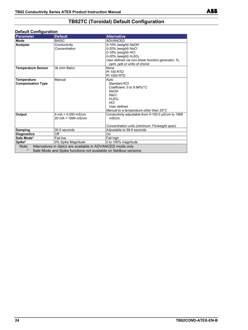
TB82TC (Toroidal) Default Configuration Default Configuration Parameter Default Alternative Mode BASIC ADVANCED Analyzer Conductivity
Concentration 0-15% (weight) NaOH 0-20% (weight) NaCl 0-18% (weight) HCl 0-20% (weight) H2SO4 User defined via non-linear function generator, %,
ppm, ppb or units of choice Temperature Sensor 3k ohm Balco None
Pt 100 RTD Pt 1000 RTD
Temperature Compensation Type
Manual Auto Standard KCl Coefficient: 0 to 9.99%/°C NaOH NaCl H2SO4 HCl User defined Manual to a temperature other than 25°C
Output 4 mA = 0.000 mS/cm 20 mA = 1999 mS/cm
Conductivity adjustable from 0-100.0 µS/cm to 1999 mS/cm
Concentration units (minimum 1%/weight span)
Damping 00.5 seconds Adjustable to 99.9 seconds Diagnostics Off On Safe Mode* Fail low Fail high Spike* 0% Spike Magnitude 0 to 100% magnitude
Note: Alternatives in Italics are available in ADVANCED mode only * Safe Mode and Spike functions not available on fieldbus versions
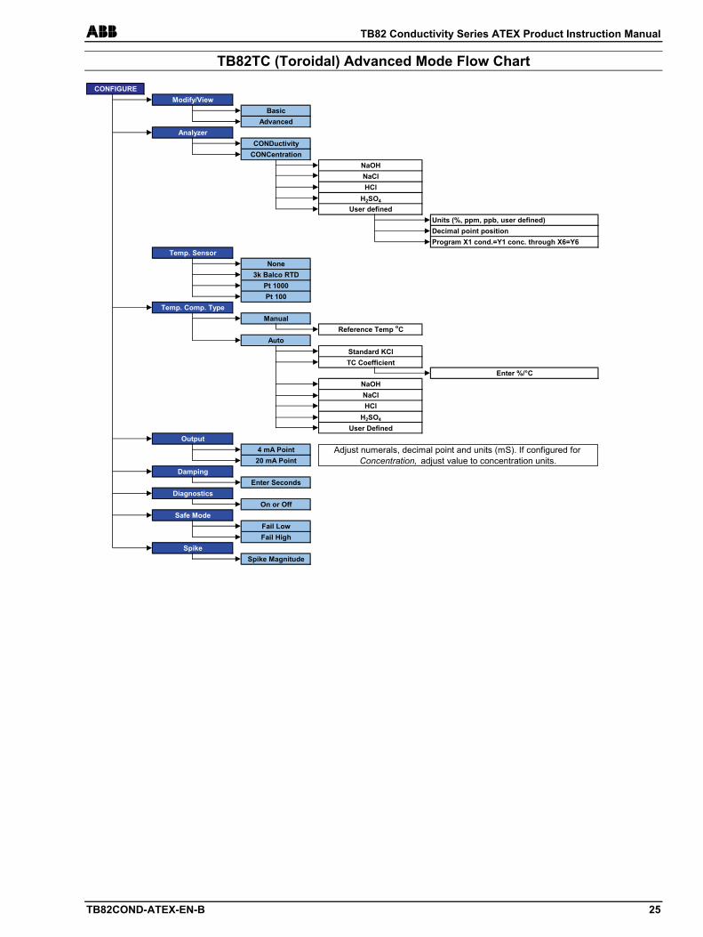
ABB TB82 Conductivity Series ATEX Product Instruction Manual
TB82COND-ATEX-EN-B 25
TB82TC (Toroidal) Advanced Mode Flow Chart
CONFIGUREModify/View
BasicAdvanced
AnalyzerCONDuctivity
CONCentrationNaOHNaClHCl
H2SO4
User definedUnits (%, ppm, ppb, user defined)Decimal point positionProgram X1 cond.=Y1 conc. through X6=Y6
Temp. SensorNone
3k Balco RTDPt 1000Pt 100
Temp. Comp. TypeManual
Reference Temp oCAuto
Standard KClTC Coefficient
Enter %/°CNaOHNaClHCl
H2SO4
User DefinedOutput
4 mA Point20 mA Point
DampingEnter Seconds
DiagnosticsOn or Off
Safe ModeFail LowFail High
SpikeSpike Magnitude
Adjust numerals, decimal point and units (mS). If configured for Concentration, adjust value to concentration units.
TB82 Conductivity Series ATEX Product Instruction Manual ABB
26 TB82COND-ATEX-EN-B
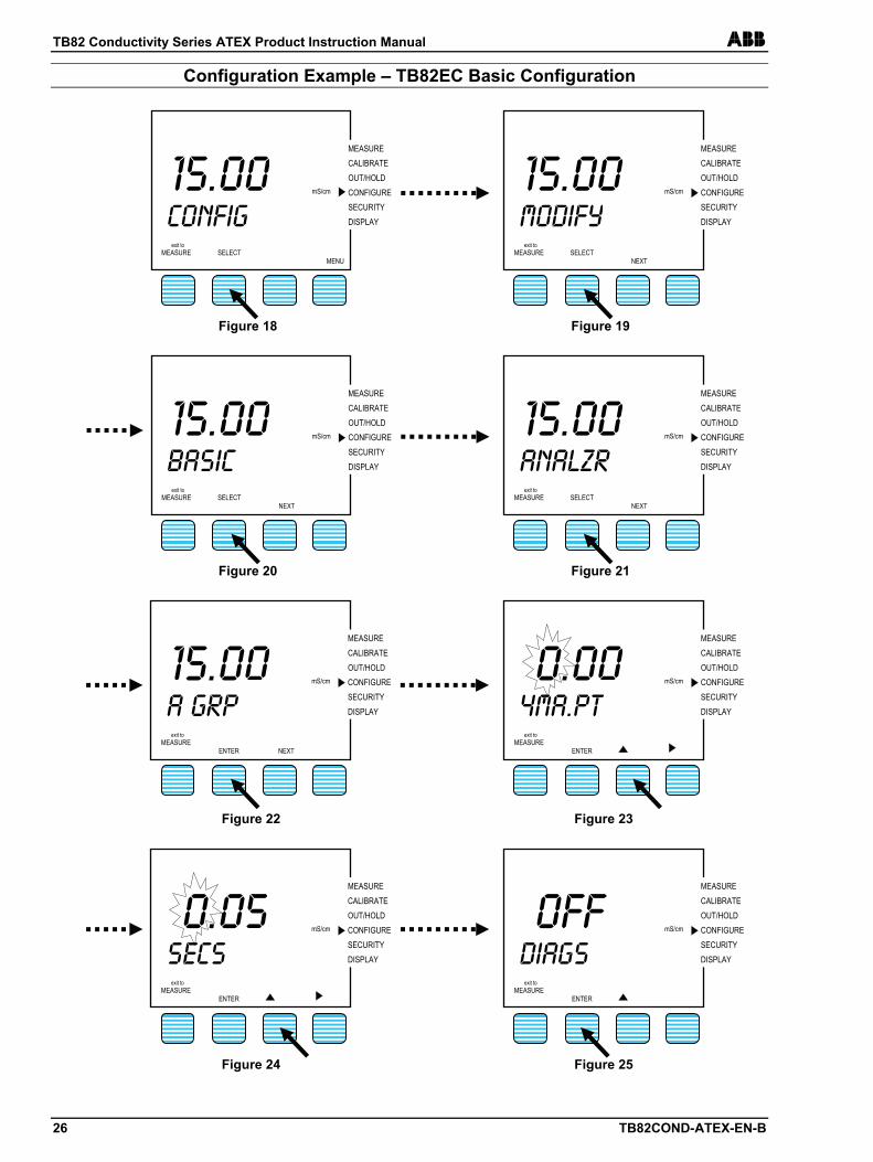
Configuration Example – TB82EC Basic Configuration
15.00 CONFIG
exit to MEASURE
SELECT
MENU
mS/cm
MEASURE CALIBRATE OUT/HOLD CONFIGURE SECURITY DISPLAY
MEASURE CALIBRATE OUT/HOLD CONFIGURE SECURITY DISPLAY
15.00 MODIFY
exit to MEASURE
SELECT
NEXT
mS/cm
Figure 18 Figure 19
MEASURE CALIBRATE OUT/HOLD CONFIGURE SECURITY DISPLAY
15.00 Basic
exit to MEASURE
SELECT
NEXT
mS/cm
MEASURE CALIBRATE OUT/HOLD CONFIGURE SECURITY DISPLAY
15.00 ANALZR
exit to MEASURE
SELECT
NEXT
mS/cm
Figure 20 Figure 21
MEASURE CALIBRATE OUT/HOLD CONFIGURE SECURITY DISPLAY
15.00
A grp exit to
MEASURE
ENTER
NEXT
mS/cm
MEASURE CALIBRATE OUT/HOLD CONFIGURE SECURITY DISPLAY
0.00 4MA.PT
exit to MEASURE
ENTER
mS/cm
Figure 22 Figure 23
MEASURE CALIBRATE OUT/HOLD CONFIGURE SECURITY DISPLAY
OFF DIAGS
exit to MEASURE
ENTER
mS/cm
0.05 SECS
exit to MEASURE
ENTER
mS/cm
MEASURE CALIBRATE OUT/HOLD CONFIGURE SECURITY DISPLAY
Figure 24 Figure 25
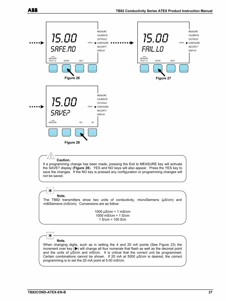
ABB TB82 Conductivity Series ATEX Product Instruction Manual
TB82COND-ATEX-EN-B 27
MEASURE CALIBRATE OUT/HOLD CONFIGURE SECURITY DISPLAY
15.00
SAFE.MD exit to
MEASURE FAULT info
ENTER
NEXT
mS/cm
MEASURE CALIBRATE OUT/HOLD CONFIGURE SECURITY DISPLAY
15.00
Fail.lo exit to
MEASURE FAULT info
ENTER
NEXT
mS/cm
MEASURE CALIBRATE OUT/HOLD CONFIGURE SECURITY DISPLAY
15.00
Save? exit to
MEASURE
YES
NO
mS/cm
Figure 28
Figure 27 Figure 26
Note. The TB82 transmitters show two units of conductivity, microSiemens (µS/cm) and milliSiemens (mS/cm). Conversions are as follow:
1000 µS/cm = 1 mS/cm 1000 mS/cm = 1 S/cm
1 S/cm = 100 S/m
Caution. If a programming change has been made, pressing the Exit to MEASURE key will activate the SAVE? display (Figure 28). YES and NO keys will also appear. Press the YES key to save the changes. If the NO key is pressed any configuration or programming changes will not be saved.
Note. When changing digits, such as in setting the 4 and 20 mA points (See Figure 23) the increment over key ( ) will change all four numerals that flash as well as the decimal point and the units of µS/cm and mS/cm. It is critical that the correct unit be programmed. Certain combinations cannot be shown. If 20 mA at 5000 µS/cm is desired, the correct programming is to set the 20 mA point at 5.00 mS/cm.
TB82 Conductivity Series ATEX Product Instruction Manual ABB
28 TB82COND-ATEX-EN-B
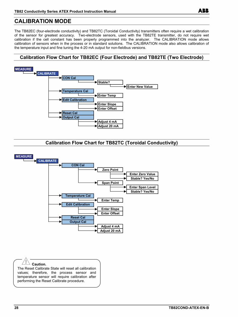
CALIBRATION MODE The TB82EC (four-electrode conductivity) and TB82TC (Toroidal Conductivity) transmitters often require a wet calibration of the sensor for greatest accuracy. Two-electrode sensors, used with the TB82TE transmitter, do not require wet calibration if the cell constant has been properly programmed into the analyzer. The CALIBRATION mode allows calibration of sensors when in the process or in standard solutions. The CALIBRATION mode also allows calibration of the temperature input and fine tuning the 4-20 mA output for non-fieldbus versions.
Calibration Flow Chart for TB82EC (Four Electrode) and TB82TE (Two Electrode)
Calibration Flow Chart for TB82TC (Toroidal Conductivity)
Caution. The Reset Calibrate State will reset all calibration values; therefore, the process sensor and temperature sensor will require calibration after performing the Reset Calibrate procedure.
MEASURECALIBRATE
CON CalStable?
Enter New ValueTemperature Cal
Enter TempEdit Calibration
Enter SlopeEnter Offset
Reset CalOutput Cal
Adjust 4 mAAdjust 20 mA
MEASURECALIBRATE
CON CalZero Point
Enter Zero ValueStable? Yes/No
Span PointEnter Span LevelStable? Yes/No
Temperature CalEnter Temp
Edit CalibrationEnter SlopeEnter Offset
Reset CalOutput Cal
Adjust 4 mAAdjust 20 mA
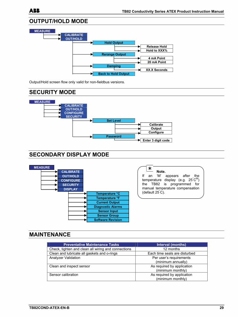
ABB TB82 Conductivity Series ATEX Product Instruction Manual
TB82COND-ATEX-EN-B 29
OUTPUT/HOLD MODE
MEASURE CALIBRATE OUT/HOLD Hold Output Release Hold Hold to XXX% Rerange Output 4 mA Point 20 mA Point Damping XX.X Seconds Back to Hold Output
Output/Hold screen flow only valid for non-fieldbus versions.
SECURITY MODE
MEASURE CALIBRATE OUT/HOLD CONFIGURE SECURITY Set Level Calibrate Output Configure Password Enter 3 digit code
SECONDARY DISPLAY MODE
MAINTENANCE
Preventative Maintenance Tasks Interval (months) Check, tighten and clean all wiring and connections 12 months Clean and lubricate all gaskets and o-rings Each time seals are disturbed Analyzer Validation Per user’s requirements
(minimum annually) Clean and inspect sensor As required by application
(minimum monthly) Sensor calibration As required by application
(minimum monthly)
MEASURECALIBRATEOUT/HOLD
CONFIGURESECURITYDISPLAY
Temperature °CTemperature °FCurrent Output
Diagnostic AlarmsSensor Input
Sensor GroupSoftware Revision
Note. If an ‘M’ appears after the temperature display (e.g. 25°CM) the TB82 is programmed for manual temperature compensation (default 25°C).
TB82 Conductivity Series ATEX Product Instruction Manual ABB
30 TB82COND-ATEX-EN-B
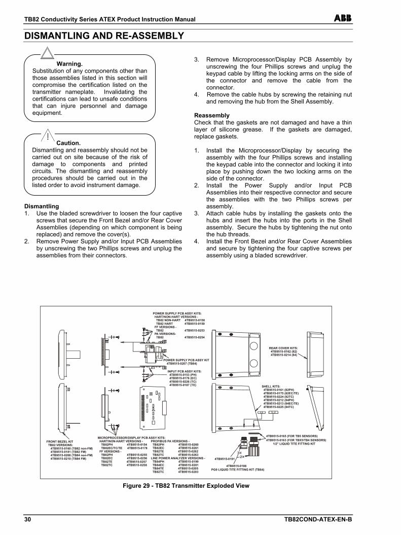
DISMANTLING AND RE-ASSEMBLY Dismantling 1. Use the bladed screwdriver to loosen the four captive
screws that secure the Front Bezel and/or Rear Cover Assemblies (depending on which component is being replaced) and remove the cover(s).
2. Remove Power Supply and/or Input PCB Assemblies by unscrewing the two Phillips screws and unplug the assemblies from their connectors.
3. Remove Microprocessor/Display PCB Assembly by
unscrewing the four Phillips screws and unplug the keypad cable by lifting the locking arms on the side of the connector and remove the cable from the connector.
4. Remove the cable hubs by screwing the retaining nut and removing the hub from the Shell Assembly.
Reassembly Check that the gaskets are not damaged and have a thin layer of silicone grease. If the gaskets are damaged, replace gaskets. 1. Install the Microprocessor/Display by securing the
assembly with the four Phillips screws and installing the keypad cable into the connector and locking it into place by pushing down the two locking arms on the side of the connector.
2. Install the Power Supply and/or Input PCB Assemblies into their respective connector and secure the assemblies with the two Phillips screws per assembly.
3. Attach cable hubs by installing the gaskets onto the hubs and insert the hubs into the ports in the Shell assembly. Secure the hubs by tightening the nut onto the hub threads.
4. Install the Front Bezel and/or Rear Cover Assemblies and secure by tightening the four captive screws per assembly using a bladed screwdriver.
Caution. Dismantling and reassembly should not be carried out on site because of the risk of damage to components and printed circuits. The dismantling and reassembly procedures should be carried out in the listed order to avoid instrument damage.
Warning. Substitution of any components other than those assemblies listed in this section will compromise the certification listed on the transmitter nameplate. Invalidating the certifications can lead to unsafe conditions that can injure personnel and damage equipment.
MICROPROCESSOR/DISPLAY PCB ASSY KITS: HART/NON-HART VERSIONS - TB82PH 4TB9515-0154 TB82EC/TC/TE 4TB9515-0178 FF VERSIONS - TB82PH 4TB9515-0255 TB82EC 4TB9515-0256 TB82TE 4TB9515-0257 TB82TC 4TB9515-0258
POWER SUPPLY PCB ASSY KITS: HART/NON-HART VERSIONS - TB82 NON-HART 4TB9515-0158 TB82 HART 4TB9515-0159 FF VERSIONS - TB82 4TB9515-0253 PA VERSIONS- TB82 4TB9515-0254
PG9 LIQUID TITE FITTING KIT (TB84)
4TB9515-0191
4TB9515-0198
1/2” LIQUID TITE FITTING KIT
4TB9515-0165 (FOR TB5 SENSORS)4TB9515-0163 (FOR TBX5/TB4 SENSORS) PROFIBUS PA VERSIONS -
TB82PH 4TB9515-0260 TB82EC 4TB9515-0261 TB82TE 4TB9515-0262 TB82TC 4TB9515-0263 LINE POWER ANALYZER VERSIONS - TB84PH 4TB9515-0199 TB84EC 4TB9515-0201 TB84TE 4TB9515-0205 TB82TC 4TB9515-0203
FRONT BEZEL KIT TB82 VERSIONS: 4TB9515-0160 (TB82 non-FM) 4TB9515-0181 (TB82 FM) 4TB9515-0208 (TB84 non-FM) 4TB9515-0210 (TB84 FM)
POWER SUPPLY PCB ASSY KIT 4TB9515-0207 (TB84)
INPUT PCB ASSY KITS: 4TB9515-0153 (PH) 4TB9515-0176 (EC) 4TB9515-0226 (TC) 4TB9515-0187 (TE)
REAR COVER KITS: 4TB9515-0162 (82) 4TB9515-0214 (84)
SHELL KITS: 4TB9515-0161 (82PH) 4TB9515-0175 (82EC/TE) 4TB9515-0224 (82TC) 4TB9515-0212 (84PH) 4TB9515-0213 (84EC/TE) 4TB9515-0225 (84TC)
Figure 29 - TB82 Transmitter Exploded View
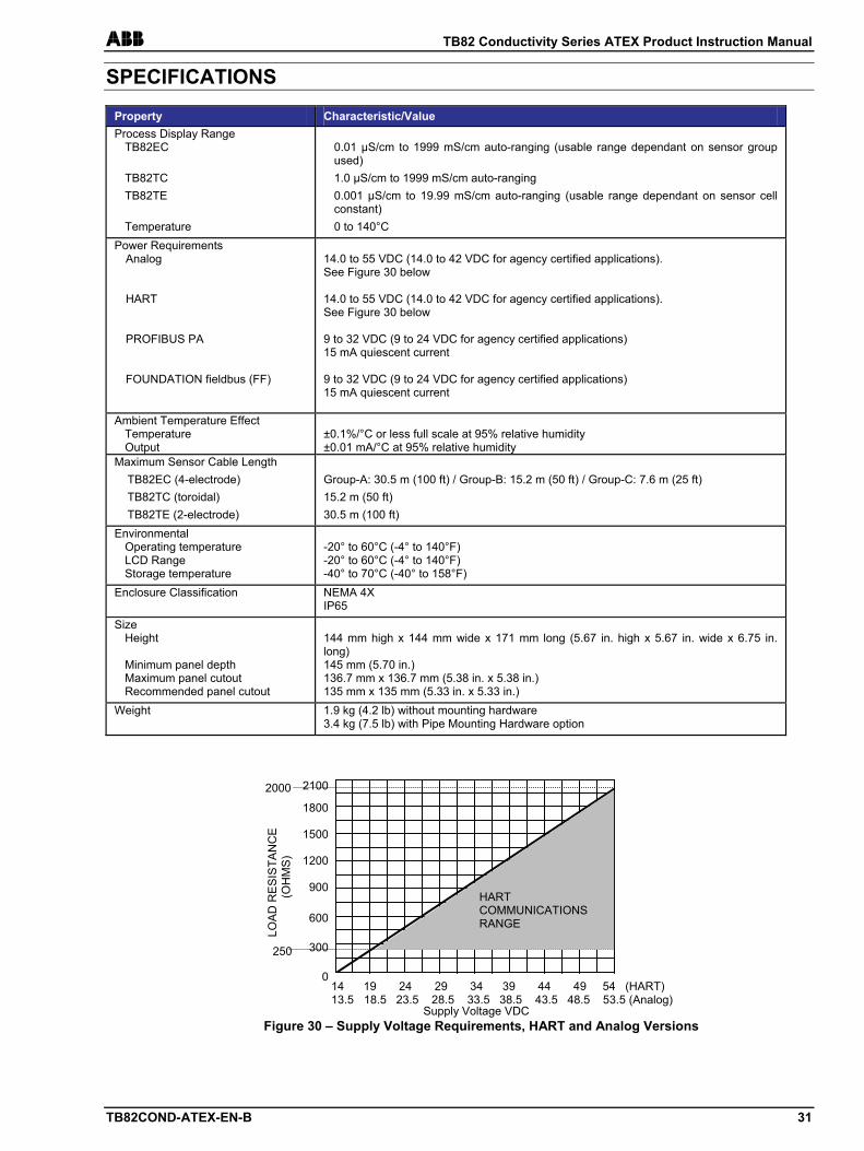
ABB TB82 Conductivity Series ATEX Product Instruction Manual
TB82COND-ATEX-EN-B 31
SPECIFICATIONS
Property Characteristic/Value Process Display Range
TB82EC TB82TC TB82TE Temperature
0.01 µS/cm to 1999 mS/cm auto-ranging (usable range dependant on sensor group used) 1.0 µS/cm to 1999 mS/cm auto-ranging 0.001 µS/cm to 19.99 mS/cm auto-ranging (usable range dependant on sensor cell constant) 0 to 140°C
Power Requirements Analog HART PROFIBUS PA FOUNDATION fieldbus (FF)
14.0 to 55 VDC (14.0 to 42 VDC for agency certified applications). See Figure 30 below 14.0 to 55 VDC (14.0 to 42 VDC for agency certified applications). See Figure 30 below 9 to 32 VDC (9 to 24 VDC for agency certified applications) 15 mA quiescent current 9 to 32 VDC (9 to 24 VDC for agency certified applications) 15 mA quiescent current
Ambient Temperature Effect Temperature Output
±0.1%/°C or less full scale at 95% relative humidity ±0.01 mA/°C at 95% relative humidity
Maximum Sensor Cable Length TB82EC (4-electrode) TB82TC (toroidal) TB82TE (2-electrode)
Group-A: 30.5 m (100 ft) / Group-B: 15.2 m (50 ft) / Group-C: 7.6 m (25 ft) 15.2 m (50 ft) 30.5 m (100 ft)
Environmental Operating temperature LCD Range Storage temperature
-20° to 60°C (-4° to 140°F) -20° to 60°C (-4° to 140°F) -40° to 70°C (-40° to 158°F)
Enclosure Classification NEMA 4X IP65
Size Height
Minimum panel depth Maximum panel cutout Recommended panel cutout
144 mm high x 144 mm wide x 171 mm long (5.67 in. high x 5.67 in. wide x 6.75 in. long) 145 mm (5.70 in.) 136.7 mm x 136.7 mm (5.38 in. x 5.38 in.) 135 mm x 135 mm (5.33 in. x 5.33 in.)
Weight 1.9 kg (4.2 lb) without mounting hardware 3.4 kg (7.5 lb) with Pipe Mounting Hardware option
250
14 19 24 29 34 39 44 49 54 (HART) 13.5 18.5 23.5 28.5 33.5 38.5 43.5 48.5 53.5 (Analog)
2100
1800
1500
1200
900
600
300
0
LOA
D R
ES
ISTA
NC
E
(OH
MS
)
2000
HART COMMUNICATIONS RANGE
Figure 30 – Supply Voltage Requirements, HART and Analog Versions Supply Voltage VDC
Products and customer supportAutomation SystemsFor the following industries:— Chemical & Pharmaceutical— Food & Beverage— Manufacturing— Metals and Minerals— Oil, Gas & Petrochemical— Pulp and Paper
Drives and Motors— AC and DC Drives, AC and DC Machines, AC Motors to
1kV— Drive Systems— Force Measurement— Servo Drives
Controllers & Recorders— Single and Multi-loop Controllers— Circular Chart and Strip Chart Recorders— Paperless Recorders— Process Indicators
Flexible Automation— Industrial Robots and Robot Systems
Flow Measurement— Electromagnetic Flowmeters— Mass Flowmeters— Turbine Flowmeters— Wedge Flow Elements
Marine Systems & Turbochargers— Electrical Systems— Marine Equipment— Offshore Retrofit and Refurbishment
Process Analytics— Process Gas Analysis— Systems Integration
Transmitters— Pressure— Temperature— Level— Interface Modules
Valves, Actuators and Positioners— Control Valves— Actuators— Positioners
Water, Gas & Industrial Analytics Instrumentation— pH, Conductivity and Dissolved Oxygen Transmitters and
Sensors— Ammonia, Nitrate, Phosphate, Silica, Sodium, Chloride,
Fluoride, Dissolved Oxygen and Hydrazine Analyzers— Zirconia Oxygen Analyzers, Katharometers, Hydrogen
Purity and Purge-gas Monitors, Thermal Conductivity
Customer supportWe provide a comprehensive after sales service via a Worldwide Service Organization. Contact one of the following offices for details on your nearest Service and Repair Centre.
USAABB Inc.Tel: +1 800 HELP 365 (435 7365)Fax: +1 860 298 7669
UKABB LimitedTel: +44 (0)1453 826661Fax: +44 (0)1453 829671
ChinaABB Engineering (Shanghai) LimitedTel: +86 (0) 21 6105 6666Fax: +86 (0) 21 6105 6992
Client WarrantyPrior to installation, the equipment referred to in this manual must be stored in a clean, dry environment, in accordance with the Company's published specification.Periodic checks must be made on the equipment's condition. In the event of a failure under warranty, the following documentation must be provided as substantiation:— A listing evidencing process operation and alarm logs
at time of failure.— Copies of all storage, installation, operating and
maintenance records relating to the alleged faulty unit.
Contact us
OI/T
B82
CO
ND
/ATE
X–E
N R
ev. D
10.2
012ABB Inc.
Process Automation843 N Jefferson StreetPO Box 831Lewisburg 24901-9509USATel: +1 304 647 4358Fax: +1 304 645 4236
ABB LimitedProcess AutomationOldends LaneStonehouseGloucestershire GL10 3TAUKTel: +44 1453 826 661Fax: +44 1453 829 671
ABB Engineering (Shanghai) Ltd.Process AutomationNo5, Lane 369, Chuangye Road201319, ShanghaiP.R. ChinaPhone: +86 (0) 21 6105 6666Fax: +86 (0) 21 6105 6992
www.abb.com
NoteWe reserve the right to make technical changes or modify the contents of this document without prior notice. With regard to purchase orders, the agreed particulars shall prevail. ABB does not accept any responsibility whatsoever for potential errors or possible lack of information in this document.
We reserve all rights in this document and in the subject matter and illustrations contained therein. Any reproduction, disclosure to third parties or utilization of its contents in whole or in parts – is forbidden without prior written consent of ABB.
Copyright© 2012 ABBAll rights reserved
TB82COND-ATEX-EN-B
Sales
Service
Software